Fairport - TV6DX - Petrol Trench Rammer - Exsel Plant & Tool Hire Ltd
Fairport - TV6DX - Petrol Trench Rammer - Exsel Plant & Tool Hire Ltd
Fairport - TV6DX - Petrol Trench Rammer - Exsel Plant & Tool Hire Ltd

Create successful ePaper yourself
Turn your PDF publications into a flip-book with our unique Google optimized e-Paper software.
OPERATOR<br />
Spare Parts &<br />
Service Manual ®<br />
<strong>Rammer</strong><br />
Blagden Street<br />
Sheffield<br />
S2 5QS<br />
ENGLAND<br />
Tel: +44 (0) 114 276 7921<br />
Fax: +44 (0) 114 272 0965<br />
Email: sales@fairport.uk.com<br />
FAIRPORT<br />
CONSTRUCTION EQUIPMENT LTD<br />
Unit 32,<br />
The Bell Centre,<br />
Newton Road,<br />
Manor Royal,<br />
Crawley,<br />
West Sussex,<br />
RH10 9FZ<br />
Tell +44 (0) 1293 534742<br />
Fax +44 (0) 1293 529056<br />
M-RAMMER TV60.doc
Preface<br />
This manual contains important information on how to use FAIRPORT Vibratory<br />
<strong>Rammer</strong> properly and safely. Read through this manual BEFORE you attempt to<br />
operate the machine.<br />
Table of Contents<br />
Preface ....................................................................................................................... 1<br />
Table of Contents ....................................................................................................... 1<br />
Safety ......................................................................................................................... 1<br />
SAFETY PICTOGRAMS USED ON FAIRPORT EQUIPMENT .................................. 2<br />
Specifications ............................................................................................................. 3<br />
Intended Use .............................................................................................................. 3<br />
Check Before Operation ............................................................................................. 3<br />
Operating Instructions ................................................................................................ 3<br />
Maintenance ............................................................................................................... 4<br />
Transportation ............................................................................................................ 4<br />
Storage....................................................................................................................... 4<br />
Troubleshooting.......................................................................................................... 5<br />
Parts List..................................................................................................................... 6<br />
Safety<br />
The following safety instructions must be followed to avoid any property damage, personal<br />
injury, or possible death.<br />
- This machine must be operated by well-trained personnel, and for its intended purpose only.<br />
The owner of the machine must observe and have the user of the machine observe,<br />
the effective labour protection regulations in the country of application.<br />
- This machine must be operated on the ground where the stability is guaranteed. When<br />
working near the rim of the excavated trenches, use the machine properly so that the machine<br />
may not collapse or fall down.<br />
- Keep the work area clean and free from obstacles.<br />
- Keep the unauthorised personnel away from the machine during the operation.<br />
- ALWAYS wear ear-protector, hard cap (helmet), dust mask, safety goggles, gloves and steel<br />
toe capped shoes during the operation.<br />
- Set the engine switch to OFF position before transportation or maintenance.<br />
- Close the fuel-shout off valve before transportation or storage.<br />
- Do not attempt to remove any cover or guard. Always check the condition of guards and<br />
covers before operation.<br />
- Never leave the engine running unattended.<br />
- The machine is heavy and must not be lifted single-handedly. Use proper hoist to lift the<br />
machine.<br />
- The engine is liable to be extremely hot during and immediately after the operation. DO NOT<br />
TOUCH THE ENGINE.<br />
- Fuel: Fuel is flammable. Handle it very carefully.<br />
• Do not smoke while filling the fuel tank.<br />
M-RAMMER TV60.doc 1
• Before refuelling, switch off the engine and allow it to cool.<br />
• Wipe off any spilt fuel from the engine and the machine.<br />
• Keep the fuel in a proper container and at the safe place.<br />
- Exhaust Fume:<br />
• The Exhaust Fume contains poisonous Carbon Monoxide.<br />
• Operate the machine only where the proper ventilation can be guaranteed.<br />
- Residual Risks:<br />
• This machine is designed to eliminate the possible risks arising from the use<br />
of it. However, risks do reside and these residual risks are not clearly<br />
recognisable and may cause personal injury or property damage or possible<br />
death. If such unpredictable and unrecognisable risks become apparent, the<br />
machine must be stopped immediately and the operator or his supervisor<br />
must take appropriate measures to eliminate such risks. It is sometimes<br />
necessary that the manufacturer must be informed of such events for future<br />
counter measuring.<br />
SAFETY PICTOGRAMS USED ON FAIRPORT EQUIPMENT<br />
M-RAMMER TV60.doc 2
Specifications<br />
ENGINE<br />
Model<br />
TV5DX<br />
<strong>TV6DX</strong><br />
Weight<br />
55 Kg<br />
63Kg<br />
122 lbs<br />
139 lbs<br />
Overall Dimensions<br />
(L x W x H)<br />
705 x 380 x 990mm<br />
27.8 x 15.0 x 39.0 in.<br />
763 x 420 x 1,045 mm<br />
30.0 x 16.5 x 41.1 in<br />
Ramming Shoe Size<br />
(L x W)<br />
332 x 250mm<br />
13.1 x 9.8 in<br />
332 x 280mm<br />
13.1 x 11.0 in<br />
Vibration Frequency 570 – 635 vpm 550 – 620 vpm<br />
Jumping Stroke<br />
30 – 40mm<br />
40 – 50mm<br />
1.2 – 1.6 in<br />
1.6 – 2.0 in<br />
Travel Speed<br />
8 – 13m/min<br />
8 – 13.6 m/min<br />
26.2 – 42.7 ft/min 26.2 – 44.6 ft/min<br />
Model<br />
Honda GX100<br />
Type<br />
4 Stroke, Air Cooled, OHC, <strong>Petrol</strong> Engine<br />
Fuel<br />
Automotive <strong>Petrol</strong><br />
Rated Output<br />
1.7 KW (2.3 HP)<br />
Maximum Output<br />
2.2 KW (3.0 HP)<br />
Fuel Tank Capacity<br />
2.0 Litre<br />
3.0 Litre<br />
3 US Gal<br />
0.80 US Gal<br />
Intended Use<br />
This machine is intended for the compaction of road base foundations, curbs and footing, and for<br />
the repair of streets, highways, sidewalks or pavements.<br />
Check Before Operation<br />
- Check the entire machine for any sign of damage or leak. Never attempt to run the machine<br />
before such damage or leak has been replaced or repaired.<br />
- Check the Engine Oil Level before operation. Place the machine on the level surface and<br />
remove the Oil Filter Cap. Check to see if the oil level is between L and H level using the oil<br />
level gauge at the filler cap.<br />
- Check the condition of Air Filter element before each use. If the filter element is<br />
contaminated, clean the element or replace it in accordance with the instruction manual for<br />
engine.<br />
- Check that the fuel is sufficient. If not, supply fuel. (See SAFETY Instruction for the handling<br />
of fuel).<br />
-<br />
Operating Instructions<br />
(Starting the Engine)<br />
- Open the Fuel Shut-off Valve at the fuel tank.<br />
- Set the Engine Switch to ON position<br />
- Set the Throttle Lever halfway between H and L position.<br />
- Move the Choke Lever to close it. When the engine is warm, let the lever partially open.<br />
- Hold the machine firmly with one hand and pull the recoil starter with the other hand until<br />
the feel resistance.<br />
- Then, pull the recoil starter briskly to start the engine.<br />
- Move the Choke Lever to OPEN position and let the engine run at idle for 2 to 3 minutes.<br />
-<br />
(Operating the Machine)<br />
M-RAMMER TV60.doc 3
- Move the throttle lever quickly to H position.<br />
o Move the lever quickly. Slow setting may cause damage to the centrifugal clutch.<br />
o Always set the throttle lever to the highest position during operation. Improper<br />
setting may cause irregular tamping motion and premature wear of the machine.<br />
o The engines’ maximum revolution has been set at the factory to produce the<br />
optimum engine power. DO NOT attempt to alter this setting.<br />
- At the maximum engine revolution, the machine gives impact to the ground while moving<br />
forward to compact the lift.<br />
o Do not put pressure on the operation handle during the operation. The jumping<br />
motion would be hindered and premature wear or tear may result.<br />
- Do not tilt the machine too much during the operation. Try to keep the entire sole of the<br />
ramming shoe on the ground. Otherwise, premature wear or tear of the ramming shoe<br />
may result.<br />
- When compacting on damp soil, put the wire to the Pull Fixture and have the other person<br />
pull the rope to assist the forward movement.<br />
(Stopping the machine)<br />
- Move the throttle lever to L position and let the engine run at idle for 1 to 2 minutes.<br />
- Close the Engine Switch to OFF position to stop the engine.<br />
Maintenance<br />
- The height of the handle can be adjusted by loosening three bolts at each side of the<br />
Operation handle and retighten them at the desire handle height.<br />
- For the maintenance of Engine, refer to the Instruction manual for engine.<br />
- Check the tightness of every bolt and nut at every 8 hours of operation. Retighten if<br />
necessary.<br />
- Replace the oil in the ramming cylinder after first 20 hours of operation. Henceforth, replace the oil<br />
at every 200 hours of operation.<br />
- Remove the Oil Filler Plug at the Protector and tilt the machine to drain the old oil.<br />
- Place the machine on the level surface at the upright position and supply new oil. Do not overfill with<br />
the oil. (Quantity: TV5DX, <strong>TV6DX</strong>, = 700cc, TV72DX =<br />
800 cc) Recommended Oil: SAE 10W30<br />
Transportation<br />
- Before transportation, confirm that the fuel shut-off valve is closed. It is recommended to<br />
consume all the fuel in the fuel line and the chamber of the carburetor by running the<br />
engine at idle, while the fuel shut-off valve is closed. The engine will stop after all the fuel<br />
remaining has been consumed. Then, set the engine switch to OFF position.<br />
- Be sure to let the engine cool off before transportation.<br />
- Place the machine in the upright position during the operation if at all possible.<br />
- If the machine needs to be laid on the floor of the vehicle, lay the machine to the right<br />
(when viewed from the operator’s position). Never let the carburettor of the engine face<br />
downwards, or the engine oil may get into the carburettor or air cleaner to cause starting<br />
difficulties.<br />
- Tie the machine firmly to the vehicle during the transportation.<br />
- Lifting the machine:<br />
o Before lifting the machine, check the condition of the Rubber Isolator for the<br />
Handle. If there is any sign of cracking or wear, replace the Rubber Isolator before<br />
lifting the machine.<br />
o Follow the applicable safety instruction for the use of hoist or lift.<br />
Storage<br />
- Make sure that the engine is completely cooled off.<br />
M-RAMMER TV60.doc 4
- Wipe off any dirt or oil on the machine.<br />
- Put the cover over the machine.<br />
- For long-term storage, remove fuel from the fuel tank. Also remove fuel remaining in the<br />
fuel line and the chamber of the carburettor.<br />
To drain fuel from the chamber of<br />
the carburettor, remove the Drain Plug provided at the chamber and remove the fuel.<br />
Troubleshooting<br />
Trouble Possible Causes Countermeasure<br />
Engine won’t start Fuel is insufficient Refuel with Automotive<br />
petrol.<br />
Fuel Cock is closed. Open the fuel cock.<br />
Engine switch is set to Set the switch to ON.<br />
OFF position.<br />
Spark Plug<br />
contaminated or<br />
damaged.<br />
Replace the spark plug.<br />
Improper spark plug Correct the gap.<br />
gap.<br />
Engine stops suddenly, See above.<br />
See above.<br />
or stops when RPM is<br />
increased.<br />
Main jet of carburettor<br />
being clogged with dirt<br />
Take out the main jet<br />
from carburettor and<br />
clean the jet with<br />
compressed air.<br />
Air Filter Element dirty Clean the element.<br />
Spark Plug cap is loose. Tightly fit the plug cap to<br />
Engine runs, but the<br />
machine does not<br />
produce impact.<br />
Lack of engine power.<br />
Clutch slipping.<br />
Crank/Gear unit<br />
damaged<br />
the plug.<br />
See above.<br />
Dismantle the clutch<br />
assembly and clean the<br />
shoe and drum with<br />
proper solvent. Replace<br />
the shoe if necessary.<br />
Contact dealer.<br />
M-RAMMER TV60.doc 5
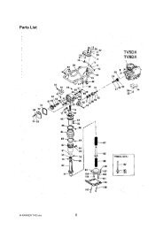
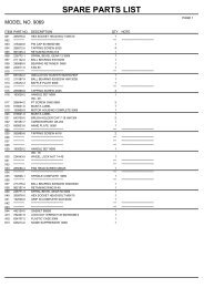
Parts List<br />
M-RAMMER TV60.doc 6
Ref. No. Part No. Description TV5DX <strong>TV6DX</strong><br />
1<br />
Engine, Honda GX100 1 1<br />
8312101000 Engine, GX120K1KRA4<br />
2 0180210358 Bolt, M10 x 35<br />
3 0251210001 Spring Washer, M10<br />
4 0933110321 Washer, 25 x 10.5 x 3.2t<br />
5<br />
6<br />
Stud Bolt, M10 x 32 4 4<br />
8372101060 Stud Bolt, M10 x 53<br />
7 8372101050 Stud Bolt, M10 x 80 1<br />
8<br />
Flange Nut, M10 4 4<br />
8372101070 Nut, M10<br />
9<br />
Fuel Hose (L200) 1 1<br />
Fuel Hose (L170) 1 1<br />
10 8302101030 Fuel Hose (L80) 1 1<br />
0851259980 Fuel Hose (L110)<br />
8372101020 Fuel Hose (L160)<br />
11<br />
8002101040 Hose Clamp 4 4<br />
8401130200 Hose Clamp<br />
12 8002107010 Line Filter 1 1<br />
13<br />
8442104003 Fuel Tank Compl. 1<br />
8392102003 Fuel Tank Compl. 1<br />
14 8442106000 Fuel Filter 1 1<br />
15 8401130502 Fuel Tank Cap Compl 1 1<br />
16 8111130300 Fuel Strainer Assy 1 1<br />
17 8442105000 Grommet 1 1<br />
18 0401401601 O Ring, S16 1 1<br />
19 0170208254 Bolt, M8 x 25 2 2<br />
20 0933110201 Washer, t1.6 x 8.5 x 25 2 2<br />
21 0251208001 Spring Washer, M8 2 2<br />
22 0902010810 Nyloc Nut, M8 2 2<br />
23 844210200 Centrifugal Clutch 1 1<br />
24 8442102030 Side Plate (A) 1 1<br />
25 8442102040 Side Plate (B) 1 1<br />
26<br />
Woodruf Key 1 1<br />
0312104133 Woodruf Key<br />
27 0181412370 Nut, M12 (Fine-Thread) 1 1<br />
28 0251212001 Spring Washer, M12 1 1<br />
29<br />
30<br />
8442103000 Clutch Housing 1 1<br />
31 0180208208 Bolt, M8 x 20, 8T 1 1<br />
32 0251208001 Spring Washer, M12 1 1<br />
33 0933110221 Washer, t3.2 x 8.5 x 25 1 1<br />
34<br />
Engine Guard 1<br />
8372105000 Engine Stay 1<br />
35<br />
0180208308 Bolt, M8 x 30, 8T 4<br />
0180208458 Bolt, M8 x 45, 8T 2<br />
36 0251208001 Spring Washer, M8 4 2<br />
37 0933110121 Washer, t4.5 x 8.5 x 25 4<br />
0256308110 Washer, M8 2<br />
38 0902010810 Nyloc Nut, M8 2<br />
39 8122301000 Operation Handle 1<br />
8302301000 Operation Handle 1<br />
40 8442302000 Rubber Isolator for Handle 2<br />
M-RAMMER TV60.doc 7
8601121000 Rubber Isolator for Handle 2<br />
41 0180208208 Bolt, M8 x 20, 8T 4 4<br />
42 0251208001 Spring Washer, M8 4 4<br />
43 0180208204 Bolt, M8 x 20 6 6<br />
44 0251208001 Spring Washer, M8 6 6<br />
45 0256308110 Washer, M8 6 6<br />
46 8531110000 Throttle Lever 1 1<br />
0910011020 Throttle Lever<br />
47 8002302000 Throttle Wire 1 1<br />
5401811000 Throttle Wire<br />
48 0921011030 Hose Band 2 2<br />
49<br />
50 092114E64S Wire Clamp 2 2<br />
092116EE4J Wire Clamp<br />
51 8442501004 Crank Case 1<br />
8392501002 Crank Case 1<br />
52 8442502000 Crank Case Cover 1<br />
8392502000 Crank Case Cover 1<br />
53 8442503000 Packing 1<br />
8392503000 Packing 1<br />
54 0180206254 Bolt, M6 x 25, 4T 8 8<br />
55 0251206001 Spring Washer, M6 8 8<br />
56 0256906110 Washer, M6 8 8<br />
57 8442504001 Shaft Cover 1<br />
8392504001 Shaft Cover 1<br />
58 0401103401 O Ring, P34 1<br />
0401403901 O Ring, S39 1<br />
59 0180106164 Bolt, M6 x 16 2<br />
60 0251206001 Spring Washer, M6 2<br />
61 8442505101 Crankshaft 1<br />
8392505100 Crankshaft 1<br />
62 0521163061 Bearing, 6306 1<br />
05221162071 Bearing, 6207 1<br />
63 0521562041 Bearing, 6204LLU 1<br />
0521563051 Bearing, 6305LLU 1<br />
64 0804204700 Snap Ring, R47 1<br />
0804206200 Snap Ring, R62 1<br />
65 0180208168 Bolt, M8 x 16, 8T 1<br />
66 0251208001 Spring Washer, M8 1<br />
67 0933110221 Washer t3.2 x 8.5 x 25 1<br />
68 0804102500 Snap Ring, S25 1<br />
69 8442506100 Pinion Shaft 1 1<br />
70 0521562041 Bearing, 6204LLU 1 1<br />
71 0521569071 Bearing, 6907LLU 1 1<br />
72 0402140581 Oil Seal, SC40588 1 1<br />
73 0311205200 Key, 5 x 5 x 20 1 1<br />
74 8601237000 Connecting Rod 1 1<br />
75 0521162041 Bearing, 6204 1 1<br />
76 0804204700 Snap Ring, R47 1 1<br />
77 0804102000 Snap Ring, S20 1 1<br />
78 8601214000 Piston Pin 1 1<br />
79 0804101600 Snap Ring, S16 1 1<br />
80 8442801000 Guiding Cylinder 1<br />
8312801000 Guiding Cylinder 1<br />
81 8562801000 Guiding Cylinder<br />
0401209001 O Ring, G90 1<br />
0401210501 O Ring, G105 1<br />
M-RAMMER TV60.doc 8
82 0180210304 Bolt, M10 x 30, 4T 4<br />
0180210308 Bolt, M10 x 30,8T 4<br />
83 0251210001 Spring Washer, M10 4 4<br />
84 8451320000 Bellows 1 1<br />
8601320000 Bellows<br />
Ref. Part No. Description TV5DX <strong>TV6DX</strong><br />
No.<br />
845132100 Bellows Stop Band 2 2<br />
85 0<br />
870142000 Bellows Stop Band<br />
86 844280200<br />
Spacer 2 2<br />
0<br />
844280300<br />
Protector 1 1<br />
87<br />
1<br />
856280200<br />
Protector<br />
0<br />
88 845131200<br />
Oil Plug 1 1<br />
0<br />
89 844131300<br />
Packing 1 1<br />
0<br />
844300100 Spring Cylinder 1 1<br />
90<br />
2<br />
856300100 Spring Cylinder<br />
0<br />
040120800 O Ring, G80 2 2<br />
91<br />
1<br />
040120950 O Ring, G95<br />
0<br />
844301101<br />
Ram Rod 1 1<br />
92<br />
3<br />
856300200 Ram Rod Compl<br />
0<br />
93 844300202 Piston Guide 1 1<br />
2<br />
94 018181814 Nut, M18 x p1.6 1 1<br />
0<br />
844300300<br />
Guide Joint 1 1<br />
95<br />
0<br />
856300300<br />
Guide Joint<br />
0<br />
96 080811604 Spring Pin, 6 x 45 1 1<br />
5<br />
811300400 Spring Compl, Upper 1<br />
0<br />
97<br />
831300401 Spring Compl, Upper 1<br />
0<br />
856300400 Spring Compl, Upper<br />
1<br />
811300600 Spring Compl, Lower 1<br />
0<br />
98<br />
831300402 Spring Compl, Lower 1<br />
1<br />
856300500 Spring Compl, Lower<br />
0<br />
99<br />
811300511<br />
Foot Stand 1<br />
0<br />
M-RAMMER TV60.doc 9
811300512<br />
0<br />
011120512<br />
4<br />
844320200<br />
0<br />
839320200<br />
0<br />
090412121<br />
2<br />
090511220<br />
100<br />
1<br />
030179012<br />
0<br />
017610045<br />
1<br />
101<br />
017610040<br />
1<br />
017610030<br />
1<br />
102<br />
017610025<br />
1<br />
103 025231000<br />
1<br />
844301101<br />
2<br />
833320100<br />
104<br />
0<br />
856320100<br />
0<br />
105 891164000<br />
0<br />
106 891164000<br />
0<br />
107 025131200<br />
2<br />
108 090201121<br />
0<br />
109 811320600<br />
0<br />
Bottom Plate 1<br />
Screw, M5 x 12 3<br />
Foot Stand 1<br />
Foot Stand<br />
Drain Bolt, M12 x 12 1<br />
Packing 1<br />
Drain Plug, 1/8” 1<br />
Socket Head Bolt, M10 x 45 4<br />
Socket Head Bolt, M10 x 40 4<br />
Socket Head Bolt, M10 x 30 4<br />
Socket Head Bolt, M10 x 25 4<br />
Coned Disc Washer, M10 8 8<br />
Ramming Shoe, W=250mm 1<br />
Ramming Shoe, W=280mm 1<br />
Ramming Shoe, W=300mm<br />
Square Flat Head Bolt, 2 2<br />
M12x69<br />
Square Flat Head Bolt, 2 2<br />
M12x69<br />
Spring Washer, M12 4 4<br />
Nyloc Nut, M12 4 4<br />
Pull Fixture 1 1<br />
M-RAMMER TV60.doc 10