CSE 2000 G2 Basisgerät -03.qxp - Hirschmann
CSE 2000 G2 Basisgerät -03.qxp - Hirschmann
CSE 2000 G2 Basisgerät -03.qxp - Hirschmann

Create successful ePaper yourself
Turn your PDF publications into a flip-book with our unique Google optimized e-Paper software.
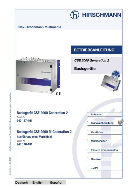
Triax-<strong>Hirschmann</strong> Multimedia<br />
BETRIEBSANLEITUNG<br />
<strong>CSE</strong> <strong>2000</strong> Generation 2<br />
Basisgeräte<br />
046069-101-03-0907 Alle Rechte, sowie Druckfehler, Irrtümer und Änderungen vorbehalten<br />
Basisgerät <strong>CSE</strong> <strong>2000</strong> Generation 2<br />
Bestell-Nr.<br />
940 137-101<br />
Basisgerät <strong>CSE</strong> <strong>2000</strong> M Generation 2<br />
Ausführung ohne Verteilfeld<br />
Bestell-Nr.<br />
940 146-101<br />
Antennen<br />
Signalaufbereitung<br />
Verstärker<br />
Multischalter<br />
Passive Komponenten<br />
Receiver<br />
catTV<br />
Deutsch English Español
Lieferumfang • Übersicht<br />
Lieferumfang<br />
1 Basisgerät<br />
1 Abschlusswiderstand, auf Buchse Durchschleifeingang geschraubt<br />
1 Abschlusswiderstand, beiliegend<br />
1 Betriebsanleitung<br />
Übersicht Kopfstellensystem <strong>CSE</strong> <strong>2000</strong> Generation 2<br />
Basisgeräte<br />
Typ Bestell Nr. Beschreibung<br />
<strong>CSE</strong> <strong>2000</strong> <strong>G2</strong> 940 137-101 Basisgerät<br />
<strong>CSE</strong> <strong>2000</strong> M <strong>G2</strong> 940 146-101 Basisgerät ohne Eingangsverteilung<br />
Module<br />
Typ Bestell Nr. Beschreibung<br />
CHA <strong>2000</strong> A 960 905-101 Twin-Modul SAT analog mit UKW-Modulator<br />
CHA <strong>2000</strong> U 960 906-101 Twin-Modul UKW-Umsetzer<br />
CHC 2022 MI1 940 149-102 Twin-Modul terr. TV digital nach PAL, multinorm, CI<br />
CHC 2022 QN 940 150-101 Twin-Modul terr. TV digital nach QAM<br />
CHC 2022 S1 940 147-102 Twin-Modul terr. TV digital nach PAL, stereo<br />
CHC 2022 SI1 940 148-102 Twin-Modul terr. TV digital nach PAL, stereo, CI<br />
CHD 2022 MI1 940 145-102 Twin-Modul SAT-TV digital nach PAL/SECAM, Multinorm, CI<br />
CHD 2022 Q 940 166-101 Twin-Modul SAT-TV digital nach QAM<br />
CHD 2022 QN 940 012-101 Twin-Modul SAT-TV digital nach QAM, NIT + Stuffing<br />
CHD 2022 S1 940 141-102 Twin-Modul SAT-TV digital nach PAL/SECAM, stereo<br />
CHD 2022 SI1 940 144-102 Twin-Modul SAT-TV digital nach PAL/SECAM, stereo, CI<br />
CHE <strong>2000</strong> D 960 901-101 Dekoderschnittstelle für analoge Module…<br />
CHE 2022 QN 940 223-101 Twin-Modul SAT-TV digital nach QAM, NIT + Stuffing, HDTV<br />
CHD 2022 U 940 161-101 Twin-Modul SAT digital mit UKW-Modulator<br />
CHM <strong>2000</strong> M 960 913-101 Twin-Modul Audio/Video Modulator, multinorm<br />
CHM 2001 M 961 109-101 Single-Modul Audio/Video Modulator, multinorm<br />
CHM <strong>2000</strong> S 960 912-101 Twin-Modul Audio/Video Modulator, stereo<br />
CHS <strong>2000</strong> M 960 898-101 Twin-Modul Sat-TV analog, multinorm<br />
CHS <strong>2000</strong> S 960 899-101 Twin-Modul Sat-TV analog, stereo<br />
CHT <strong>2000</strong> B 960 911-101 Single-Modul terrestrisch TV analog, multinorm für Band I/III<br />
CHT <strong>2000</strong> M 960 973-101 Twin-Modul terrestrisch TV analog, multinorm<br />
CHT 2001 M 961 105-101 Single-Modul terrestrisch TV analog, multinorm<br />
CHT <strong>2000</strong> T 960 903-101 Twin-Modul terrestrisch TV analog, stereo<br />
CHV <strong>2000</strong> U 960 904-101 Single-Modul UKW-Breitbandverstärker<br />
CHZ 2020 R 940 301-001 Fernprogrammierung mit PC-Programmiersoftware<br />
7 laufend aktualisierte Typenliste unter www.triax-hirschmann.de<br />
Copyright © Triax-<strong>Hirschmann</strong> Multimedia GmbH<br />
Kopien und Verfielfältigungen nur mit Genehmigung des Urhebers<br />
2<br />
Basisgerät <strong>CSE</strong> <strong>2000</strong> Generation 2
Inhalt<br />
Inhalt<br />
Hinweise, Erläuterungen ................................................................. 4<br />
Bestimmungsgemäße und sachwidrige Verwendung ................................... 4<br />
ESD-Schutzhinweise .......................................................................... 4<br />
Begriffserläuterungen ........................................................................ 4<br />
Recyclinghinweis .............................................................................. 4<br />
Beschreibung ................................................................................... 5<br />
Allgemeine Funktionsbeschreibung ........................................................ 5<br />
Innenansicht ................................................................................... 5<br />
Eingangsverteilfeld ............................................................................ 6<br />
Anschlüsse .................................................................................... 6<br />
Technische Daten ........................................................................... 7<br />
Montage ........................................................................................ 8<br />
Wandmontage ................................................................................. 8<br />
Montage im 19"-Schrank .................................................................... 8<br />
Software ........................................................................................ 9<br />
Inbetriebnahme .............................................................................. 9<br />
Vorbereitende Arbeiten ....................................................................... 9<br />
Einschieben und Herausnehmen von Modulen ........................................... 9<br />
Anschließen an die HF-Eingänge .......................................................... 10<br />
Anschließen an HF-Ausgang und Durchschleifeingang ................................ 10<br />
Einstellen des HF-Ausgangspegels ........................................................ 10<br />
Programmierung / Bedienung ............................................................. 11<br />
Hinweise zum Menü ...................................................................... 11<br />
Tastenbeschreibung ....................................................................... 11<br />
Menüablauf................................................................................... 12<br />
Basisgerät <strong>CSE</strong> <strong>2000</strong> Generation 2<br />
3
Hinweise, Erläuterungen<br />
Hinweise, Erläuterungen<br />
Bestimmungsgemäße und sachwidrige Verwendung<br />
Dieses Produkt darf nur gemäß dieser<br />
Anleitung betrieben werden. Jede andere<br />
sachwidrige Verwendung führt zum Erlöschen<br />
des Garantieanspruchs.<br />
ESD-Schutzhinweise<br />
Das Basisgerät ist mit elektrostatisch empfindlichen<br />
Bauteilen bestückt. Diese können<br />
durch die Einwirkung eines elektrischen<br />
Feldes oder durch Ladungsausgleich beim<br />
Berühren zerstört oder in der Lebensdauer<br />
beeinflusst werden.<br />
Beachten Sie unbedingt die folgenden<br />
Schutzmaßnahmen für elektrostatisch<br />
gefährdete Baugruppen:<br />
➧ Bevor Sie Arbeiten an einer gefährdeten<br />
Baugruppe durchführen, stellen Sie einen<br />
elektrischen Potentialausgleich zwischen<br />
sich und ihrer Umgebung her, z. B. durch<br />
ein Handgelenkband, das Sie an das<br />
Basisgerät anklemmen; das Basisgerät<br />
muss dabei unbedingt über die Erdungsklemme<br />
geerdet sein!<br />
➧ Für den Ausbau einer Baugruppe aus dem<br />
Basisgerät entnehmen Sie diese erst jetzt<br />
dem Basisgerät.<br />
➧ Für den Einbau einer Baugruppe in das<br />
Basisgerät nehmen Sie die Baugruppe erst<br />
jetzt aus dem leitfähigen Beutel heraus.<br />
➧ Lagern Sie die Baugruppe außerhalb des<br />
Basisgerätes nur in einem leitfähigen ESD-<br />
Schutzbeutel.<br />
➧ Bewahren Sie den ESD-Schutzbeutel für<br />
Lagerung oder eventuelle Rücksendung<br />
des Moduls auf.<br />
Für den sicheren Umgang mit elektrostatisch<br />
gefährdeten Baugruppen sind ESD-Schutz-<br />
Feldausrüstungen erhältlich.<br />
Weitere Informationen über elektrostatisch<br />
gefährdete Baugruppen finden Sie in den<br />
Normen DIN EN 61340-5-1 und<br />
DIN EN 61340-5-2: Schutz von elektronischen<br />
Bauelementen gegen elektrostatische<br />
Phänomene.<br />
Begriffserläuterungen<br />
WARNUNG:<br />
Weist darauf hin, dass das<br />
Nichtbeachten der gegebenen<br />
Vorsichtsmaßnahmen zu<br />
Personen- oder Geräteschäden<br />
führen kann.<br />
ACHTUNG:<br />
Weist darauf hin, dass das<br />
Nichtbeachten der gegebenen<br />
Vorsichtsmassnahmen zu<br />
Sachbeschädigungen führen<br />
kann.<br />
Recyclinghinweis<br />
HINWEIS:<br />
Anmerkungen mit Tipps und<br />
Informationen für den praktischen<br />
Einsatz.<br />
Dieses Produkt ist nach seiner<br />
Verwendung entsprechend den<br />
aktuellen Entsorgungsvorschriften<br />
Ihres Landkreises/Landes/Staates<br />
als Elektronikschrott einer geordneten<br />
Entsorgung zuzuführen.<br />
4 Basisgerät <strong>CSE</strong> <strong>2000</strong> Generation 2
Beschreibung<br />
Beschreibung<br />
Allgemeine<br />
Funktionsbeschreibung<br />
<strong>CSE</strong> <strong>2000</strong> Generation 2 ist sehr flexibel im<br />
Aufbau und auf die Erfordernisse von Gemeinschaftsanlagen<br />
abgestimmt. Das Basisgerät<br />
kann mit den entsprechenden Modulen<br />
für jeden individuellen Bedarf ausgerüstet<br />
werden.<br />
Features:<br />
➧ Aufnahme von bis zu 8 Einzel- oder Twin-<br />
Modulen<br />
➧ programmierbares Eingangsverteilfeld mit 6<br />
SAT-Eingängen und 16 Ausgängen<br />
➧ Ausgangsverstärker mit 108 dBµV Ausgangspegel,<br />
Pegelsteller -10 dB (die Einzelmodule<br />
verfügen zusätzlich über einen<br />
Pegelsteller, um die jeweiligen Ausgangspegel<br />
untereinander anzugleichen)<br />
➧ 6-Tasten-Bedienteil zur Programmierung<br />
des SAT-Eingangs und der Module.<br />
➧ Serielle Schnittstelle Submin-D für<br />
Software-Update und Service<br />
➧ Remoteschnittstelle RJ 45 zur Fernprogrammierung<br />
(mit Zubehör CHZ 2020 R)<br />
➧ Stabiles, geschirmtes Metallgehäuse<br />
- seitliche Winkel zur Wandmontage,<br />
alternativ zur Befestigung im 19"-Schrank<br />
- Erdungsklemme für Potentialausgleich<br />
➧ Erfüllt EN 50083-1, -2<br />
lnnenansicht<br />
6 5 4 3 2 1<br />
Oberseite:<br />
6 SAT-ZF-Eingänge<br />
Oberseite:<br />
Netzanschluss<br />
8b 7b 6b 5b 4b 3b 2b 1b<br />
8a 7a 6a 5a 4a 3a 2a 1a<br />
8 7 6 5 4 3 2 1<br />
Programmierbares<br />
Eingangsverteilfeld mit<br />
16 SAT-Ausgängen<br />
Verstärker, 108 dBµV<br />
Ausgangspegel, mit<br />
Pegelsteller –10 dB<br />
8 Modulsteckplätze<br />
Rückwandplatine<br />
mit Stromversorgung<br />
und Datenbus<br />
Pegelsteller<br />
Modul, –20 dB<br />
2 eingesetzte<br />
Module<br />
Schnittstelle f.<br />
PC-Anschluss<br />
6-Tasten-Bedienteil<br />
mikroprozessorgesteuert<br />
Messbuchse<br />
-30 dB<br />
Abb. 1: Geöffnetes Basisgerät mit 2 eingesetzten Modulen<br />
Basisgerät <strong>CSE</strong> <strong>2000</strong> Generation 2 5
Beschreibung • Anschlüsse<br />
Eingangsverteilfeld<br />
➧ Das Eingangsverteilfeld besitzt sechs Sat-<br />
Eingänge und 16 Sat-Ausgänge.<br />
Es stellt für jeden Modulplatz zwei Ausgänge<br />
bereit, siehe Abb. 1.<br />
Single-Module nutzen jeweils nur den<br />
Ausgang in der unteren a-Reihe. Twin-<br />
Module nutzen auch die darüber<br />
befindliche b-Reihe. Jedes Twin-Modul ist<br />
dadurch in der Lage zwei voneinander<br />
unabhängige Kanäle zu verarbeiten.<br />
➧ Die Sat-ZF-Eingänge des elektronischen<br />
Eingangsverteilfeldes können (entsprechend<br />
der Eingangsverkabelung) softwaremäßig<br />
beliebig auf die HF-Eingangsbuchsen der<br />
jeweiligen Module geschaltet werden. Daher<br />
bitte bereits bei der Verkabelung beachten:<br />
Modulplätze 1-6:<br />
- Wählbar sind die Sat-ZF-Eingänge<br />
SAT 1+2+3+4.<br />
Modulplätze 7-8:<br />
- Wählbar sind die Sat-ZF-Eingänge<br />
SAT 1+2+3+4 oder<br />
SAT 1+2+5+6 .<br />
vgl. Menüpunkt “Sat-Routing”, S. 12/13<br />
➧ LNB-Versorgung<br />
Die Sat-Eingänge 1, 3, 5 und 6 können ein<br />
LNB fernversorgen. Das Einstellen der<br />
Versorgungsspannung (off, 13 V, 18 V)<br />
erfolgt für jeden Sat-Eingang einzeln über<br />
das Bedienteil. Die Einstellung im<br />
Lieferzustand ist “off”.<br />
Anschlüsse<br />
Geräteoberseite<br />
Geräteunterseite<br />
6 Sat-Eingänge,<br />
F-Buchsen, 75 Ω<br />
Erdungsklemme für<br />
Potentialausgleich,<br />
Schraubanschluss<br />
serielle Schnittstelle,<br />
RJ 45<br />
Netzanschluss<br />
Befestigungswinkel<br />
HF-Ausgang,<br />
Messbuchse<br />
F 75 Ω<br />
Durchschleifeingang,<br />
F 75 Ω<br />
Abb. 2: Geräteoberseite mit Anschlüssen<br />
Abb. 3: Geräteunterseite mit Anschlüssen<br />
6<br />
Basisgerät <strong>CSE</strong> <strong>2000</strong> Generation 2
Technische Daten<br />
Technische Daten<br />
Allgemeine Daten<br />
Eingangsfrequenzbereich MHz 950 - 2400 MHz (Eingangsverteilung)<br />
Ausgangsfrequenzbereich MHz 47 - 862 MHz (Ausgangsverstärker)<br />
Umgebungstemperatur °C 0...50<br />
Abmessungen B x H x T mm 484 x 358 x 221<br />
Anschlüsse<br />
HF-Eingänge<br />
F-Buchse, 75 Ω<br />
HF-Ausgang/Durchschleifeingang<br />
F-Buchse, 75 Ω<br />
PC-Schnittstelle<br />
Submin-D-Buchse, 9-polig<br />
Fernsteuerschnittstelle<br />
8pol. RJ 45-Buchse<br />
Stromversorgung<br />
Netzspannung<br />
200 - 250 V~, 50 - 60 Hz<br />
Leistungsaufnahme W max. 180 (vollbestückt mit 8 Modulen,<br />
incl. Fernspeisung)<br />
Fernspeisespannung V off / 13 / 18, umschaltbar<br />
Fernspeisestrom über<br />
Eingänge 1, 3, 5, 6 mA 4 x 500, in Summe max 1 A<br />
Eingangsverteilfeld<br />
Frequenzbereich MHz 950 - 2400<br />
Eingänge 6<br />
Ausgänge 16<br />
Durchgangsdämpfung, geschaltet<br />
Eing.1-6 / Ausg.1a-8b dB 12<br />
Entkopplung<br />
Eing. / Eing. dB 22<br />
Eing. / Ausg. dB 20<br />
Eingangspegelbereich, empfohlen dBµV 60...84<br />
Max. Eingangspegel dBµV 84<br />
Max. Ausgangspegel dBµV 88<br />
Rückflussdämpfung Eing./Ausg. dB 10<br />
Ausgangsverstärker<br />
Frequenzbereich MHz 47 - 862<br />
Verstärkung dB 27<br />
Rauschzahl dB 9<br />
Rückflussdämpfung Eing./Ausg. dB 14<br />
Ausgangspegel<br />
CSO 60 dB IMA 16 Kanäle dBµV 111<br />
CTB 60 dB IMA 16 Kanäle dBµV 111<br />
Pegelsteller dB 0...-10<br />
Max. Ausgangspegel an<br />
Buchse HF-Ausgang dBµV 108<br />
Messausgang dB -30<br />
Durchschleifeingang<br />
Frequenzbereich MHz 47 - 862<br />
Durchgangsdämpfung dB 4<br />
Rückflussdämpfung dB 12<br />
Basisgerät <strong>CSE</strong> <strong>2000</strong> Generation 2<br />
7
Montage<br />
Montage<br />
Das Basisgerät kann an den Befestigungswinkeln,<br />
siehe Abb. 3, entweder an der Wand<br />
oder in einem 19"-Schrank montiert werden.<br />
Achten Sie bei der Befestigung darauf, dass<br />
die nachfolgend angegebenen Mindestabstände<br />
ggf. erweitert werden müssen, um<br />
genügend Raum für die Anschlüsse und für<br />
eventuelle Einbauten von Decodern oder CI-<br />
Modulen zu haben.<br />
ACHTUNG:<br />
Wandmontage<br />
HINWEIS:<br />
Die im Gerät entstehende<br />
Wärme muss entweichen<br />
können. Decken Sie deshalb<br />
die Lüftungsschlitze des<br />
Gerätes nicht ab. Wärmestau<br />
beeinträchtigt die Lebensdauer<br />
des Gerätes.<br />
Die Kopfstelle darf weder<br />
Tropf- noch Spritzwasser<br />
ausgesetzt sein, noch dürfen<br />
mit Flüssigkeit gefüllte<br />
Gegenstände auf das Gerät<br />
gestellt werden.<br />
Bei der Montage an der Wand<br />
ist ein Mindestabstand von<br />
30 cm in alle Richtungen<br />
einzuhalten.<br />
30 cm<br />
30 cm<br />
30 cm<br />
30 cm<br />
Befestigen Sie das Basisgerät mit vier<br />
geeigneten Schrauben, Gewinde-Ø max.<br />
5 mm. Benutzen Sie für die Befestigung die<br />
vier vertikal verlaufenden Schlüssellöcher.<br />
Befestigungsabstand der Löcher<br />
vertikal: 286 mm<br />
horizontal: 458,5 mm<br />
Montage im 19"-Schrank<br />
HINWEIS:<br />
Für die Montage von 4 Basisgeräten<br />
der <strong>CSE</strong> <strong>2000</strong> <strong>G2</strong> sind<br />
min. 44 HE, für 3 Basisgeräte<br />
sind min. 34 HE, für 2 Basisgeräte<br />
sind min. 23 HE<br />
Schrankhöhe erforderlich.<br />
Das Basisgerät mit der höchsten Leistungsaufnahme<br />
(z.B. <strong>CSE</strong> <strong>2000</strong> <strong>G2</strong> bestückt mit 8<br />
SAT-Modulen) ist im 19" Schrank ganz oben<br />
zu platzieren. Das Basisgerät mit geringster<br />
Leistungsaufnahme (z.B. terr. Module) ist im<br />
Schrank unten einzubauen. Der Abstand<br />
zwischen den Geräten sowie zum Boden<br />
bzw. Dach muss mindestens 2 HE betragen.<br />
Belüftung<br />
➧ Umgebungsemperatur bis 25° C:<br />
Schrankdach mit Abstandsbolzen mind. 2<br />
cm höher setzen. Für ausreichende<br />
Kaltluftzufuhr am 19" Schrank unten<br />
sorgen (z.B. durch Kiemenbleche im<br />
Schranksockel).<br />
➧ Umgebungsemperatur von 25°-40° C:<br />
Zusätzlich muss eine Zwangsbelüftung<br />
durch Einschublüfter nach 1. und 3. Gerät<br />
von oben erfolgen. Oberhalb und unterhalb<br />
des Lüftereinschubs ist jeweils 1 Blindfrontplatte<br />
vorzusehen.<br />
➧ Bei höherer Umgebungstemperatur als<br />
40° C:<br />
Kühlung bzw. Klimatisierung erforderlich.<br />
Für die Montage im 19"-Schrank lösen Sie<br />
zunächst die beiden Befestigungswinkel,<br />
welche mit jeweils 3 Schrauben seitlich<br />
8 Basisgerät <strong>CSE</strong> <strong>2000</strong> Generation 2
Software • Inbetriebnahme<br />
hinten am Basisgerät befestigt sind.<br />
Befestigen Sie die Befestigungswinkel<br />
anschließend wieder seitlich vorne am<br />
Basisgerät, so dass die Befestigungsflächen<br />
diesmal nach vorne zeigen. Benutzen Sie<br />
dafür dieselben Schrauben. Befestigen Sie<br />
nun das Basisgerät mit vier Schrauben M 6<br />
durch die in den Befestigungswinkeln vorhandenen<br />
Langlöcher im 19"-Schrank.<br />
Software<br />
Die momentane Softwareversion Ihres<br />
Basisgeräts ist im Bedienmenü abrufbar:<br />
Siehe Menüpunkt “System config”, S.13.<br />
Benötigen Sie für den Betrieb eines Moduls<br />
eine höhere Softwareversion, können Sie ein<br />
Update über die serielle Schnittstelle<br />
aufspielen. Benötigtes Zubehör: Kabel<br />
RS 232 (1:1). Die jeweils aktuelle Software<br />
zum <strong>CSE</strong> <strong>2000</strong> Generation 2 Basisgerät ist<br />
abrufbar unter “www.triax-hirschmann.de”.<br />
Inbetriebnahme<br />
ACHTUNG: Das Basisgerät darf nur von<br />
geschultem, autorisiertem<br />
Personal geöffnet werden!<br />
Beachten Sie, dass das Basisgerät<br />
elektrostatisch empfindliche<br />
Bauteile enthält. Halten Sie sich für den<br />
Umgang mit diesen Bauteilen an die ESD-<br />
Schutzhinweise von Seite 4 und berühren Sie<br />
nur die zur Bedienung nötigen Elemente.<br />
Vorbereitende Arbeiten<br />
ACHTUNG:<br />
Das Basisgerät muss für die<br />
vorbereitenden Arbeiten<br />
spannungsfrei sein, es darf<br />
erst nach deren Durchführung<br />
an die Betriebsspannung<br />
angeschlossen werden!<br />
• Das Sat-Empfangssystem muss montiert<br />
und empfangsbereit sein. Richten Sie<br />
daher den Satellitenreflektor korrekt auf<br />
den zu empfangenden Satelliten aus.<br />
• Halten Sie für Pegelmessungen einen<br />
Spektrumanalysator oder ein Pegelmessgerät,<br />
z. B. UPM..., bereit.<br />
Einschieben und Herausnehmen<br />
von Modulen<br />
ACHTUNG:<br />
Ziehen Sie immer zuerst den<br />
Netzstecker bevor Sie ein<br />
Modul in das Basisgerät<br />
einschieben oder aus dem<br />
Basisgerät herausnehmen!<br />
➧ Achten Sie darauf, dass die Einlaufbuchse<br />
an der Rückseite des Moduls gut in den<br />
dafür vorgesehenen Stecker auf der Rückwandplatine<br />
läuft.<br />
➧ Befestigen Sie das eingeschobene Modul<br />
an dessen Frontseite mit 2 St. der beiliegenden<br />
Linsenschrauben am Basisgerät.<br />
➧ Mit dem beigelegten HF-Kabel verbinden<br />
Sie den Ausgang des Moduls mit dem<br />
Durchschleifeingang des nächsten, rechts<br />
davon gelegenen Moduls (siehe Abb. 1) zu<br />
zwei Gruppen von je 4 Geräten<br />
➧ Die beiden Kabelenden vom Eingang des<br />
Ausgangsverstärkers werden mit dem<br />
Ausgang der beiden Modulgruppen<br />
(Steckplatz Nr. 1 bzw. Nr. 5) verbunden.<br />
Basisgerät <strong>CSE</strong> <strong>2000</strong> Generation 2 9
Inbetriebnahme<br />
➧ Das letzte Modul wird mit einem Abschlusswiderstand<br />
versehen.<br />
HINWEIS:<br />
Alle das Modul betreffenden<br />
Einstellungen werden im Modul<br />
gespeichert und bleiben bei<br />
einem Wechsel von Modulplatz<br />
oder Basisgerät erhalten.<br />
Anschließen an die HF-<br />
Eingänge<br />
ACHTUNG:<br />
Ziehen Sie immer zuerst den<br />
Netzstecker bevor Sie<br />
Anschlussarbeiten an den HF-<br />
Eingängen des Basisgerätes<br />
vornehmen!<br />
➧ Montieren Sie F-Stecker an die LNB-<br />
Ableitungen.<br />
➧ Schrauben Sie die F-Stecker auf die entsprechenden<br />
Sat-Eingänge.<br />
➧ LNB-Spannung:<br />
Benötigen Sie eine Versorgungsspannung<br />
für ein oder mehrere LNB´s, so beachten<br />
Sie, dass nur die Sat-Eingänge 1, 3, 5 und<br />
6 eine solche ausgeben können. Die<br />
Nummerierung der Sat-Eingänge erfolgt<br />
von rechts nach links, siehe S. 5, Abb. 1.<br />
Das Einstellen der Versorgungsspannung<br />
(off, 13 V, 18 V) erfolgt für jeden Sat-<br />
Eingang einzeln im Menüpunkt “Sat<br />
config”, siehe S. 13. Lieferzustand ist off.<br />
➧ Gleichen Sie die Eingangspegel an allen<br />
Eingängen an (empfohlener Pegelunterschied:<br />
5 dB max)<br />
Anschließen an HF-Ausgang<br />
und Durchschleifeingang<br />
➧ Montieren Sie einen F-Stecker an die Ableitung<br />
des Basisgerätes und schrauben<br />
Sie diese am HF-Ausgang fest (Abb. 3).<br />
➧ Bei mehreren Basisgeräten in Kaskade<br />
entfernen Sie am Durchschleifeingang den<br />
aufgeschraubten Abschlusswiderstand und<br />
schrauben die Ableitung des zweiten<br />
Basisgerätes <strong>CSE</strong> <strong>2000</strong> <strong>G2</strong> auf.<br />
Einstellen des HF-<br />
Ausgangspegels<br />
➧ Verbinden Sie den Ausgang des Basisgerätes<br />
bzw. den Messausgang mit einem<br />
Spektrum-Analysator oder einem<br />
Pegelmessgerät.<br />
➧ Regeln Sie, falls erforderlich, den Ausgangspegel<br />
der Einzelmodule von links<br />
(Modul 8) nach rechts (Modul 1) nach.<br />
Berücksichtigen Sie dabei die jeweilige<br />
Modulationsart und Bedienungsanleitung<br />
des Moduls.<br />
Halten Sie die folgenden Pegel ein, um<br />
eine störungsfreie Übertragung unterschiedlicher<br />
Signale zu gewährleisten.<br />
Ansonsten kann es Intermodulationsstörungen<br />
zwischen den Programmen<br />
geben. Dies äußert sich bei analogen<br />
Signalen in erhöhtem Rauschen oder<br />
Moirée-Störungen, bei digitalen Signalen in<br />
erhöhter Bitfehlerrate mit Blockbildung bis<br />
hin zu stehenden Bildern und Empfangsausfall.<br />
-8dB<br />
Übertragung<br />
Pegel<br />
Analog TV<br />
0 dB = Referenz<br />
FM<br />
-8...-10 dB<br />
COFDM<br />
-16 dB<br />
QPSK<br />
-16 dB<br />
16 QAM -16 dB<br />
64 QAM -10 dB<br />
128 QAM -8 dB<br />
256 QAM -4...-6 dB<br />
10 Basisgerät <strong>CSE</strong> <strong>2000</strong> Generation 2
Inbetriebnahme • Programmierung / Bedienung<br />
➧ Den Gesamtpegel stellen Sie am Pegelsteller<br />
des Ausgangsverstärkers, siehe Abb. 1,<br />
ein. Der Pegelsteller regelt das Summensignal<br />
aller Module.<br />
Bei mehreren Basisgeräten in Kaskade<br />
beachten Sie bitte, dass der Summenpegel<br />
aller kaskadierten Geräte etwa gleich groß<br />
sein sollte.<br />
.<br />
Programmierung / Bedienung<br />
Hinweise zum Menü<br />
➧ Normalbetrieb:<br />
Display ist abgedunkelt, mit Laufschrift.<br />
➧ Bei Betätigung einer beliebigen Taste wird das<br />
Bedien-Menü aktiviert.<br />
➧ Verlassen des Menüs mit der Taste “esc”<br />
➧ Wenn 3 Minuten keine Taste gedrückt wird:<br />
Rückkehr in den Normalbetrieb ohne<br />
Speichern der Eingaben<br />
Tastenbeschreibung<br />
in der unteren Zeile der zweizeiligen Anzeige),<br />
anschließend bewegt man sich mit “esc” zum<br />
vorigen Übermenü<br />
➧ 2: up / down<br />
Auswahl innerhalb eines Menüpunktes “nach<br />
oben” bzw “nach unten”<br />
➧ 3: links / rechts<br />
Bewegen innerhalb eines Menüpunktes nach<br />
links bzw. rechts zur Dateneingabe<br />
➧ 4: ok<br />
Jeweils mit “ok” gelangt man zum nächsten<br />
Menüschritt, alle Menüpunkte erreicht man<br />
nacheinander automatisch.<br />
esc<br />
1 2<br />
ok<br />
3 4 3<br />
2<br />
HINWEIS: Die eingestellten Änderungen<br />
werden sofort wirksam, aber erst<br />
nach der nächsten “Speichern”-<br />
Abfrage gespeichert (bei “ja”)<br />
bzw. in den ursprünglichen<br />
Zustand zurückgesetzt (bei<br />
“nein”).<br />
Zusatzfunktion: Steht der Cursor in der<br />
oberen Zeile der zweizeiligen Anzeige, gelangt<br />
man mit “ok” in die untere Zeile, anschließend<br />
wiederum mit “ok” zum nächsten Menüpunkt.<br />
➧ 1: esc (escape)<br />
Sie kommen jeweils einen Menüschritt zurück.<br />
Zusatzfunktion: Mit “esc” gelangt man in die<br />
obere Zeile (standardmäßig steht der Cursor<br />
Basisgerät <strong>CSE</strong> <strong>2000</strong> Generation 2<br />
11
Menübedienung<br />
Menüablauf<br />
<strong>CSE</strong> <strong>2000</strong><br />
GENERATION 2<br />
<strong>CSE</strong> <strong>2000</strong> <strong>G2</strong><br />
Channel Processing Unit<br />
0 Sat Config<br />
0 Slot Config siehe Betriebsanleitung<br />
Modul<br />
0 Sat Config<br />
gewählt SAT Input 1<br />
Astra H/H<br />
ok<br />
A.<br />
für SAT Input 1-6<br />
B.<br />
0: Satellite 1<br />
2/10 Astra<br />
Gewünschten Satellit<br />
auswählen<br />
dto.<br />
SAT Input<br />
2...6<br />
SAT Input 6<br />
Astra H/H<br />
0: Band 1 Frequenzband<br />
1: horizontal low auswählen +<br />
C.<br />
0: LO frequency 1 LO-Frequenz manuell<br />
10600 MHz<br />
eingeben<br />
D.<br />
0: LNB supply 1 LNB-Spannung<br />
1: off<br />
zu / abschalten<br />
E.<br />
0: SAT Name 1 SAT-Name nach<br />
Astra<br />
Wunsch anpassen<br />
ok<br />
esc<br />
SAT Routing<br />
7,8: 4321<br />
ok<br />
Routing 7/8<br />
1: 4321<br />
F.<br />
Zuordnung der<br />
SAT-Eingänge<br />
ok<br />
esc<br />
Save settings<br />
no >yes<br />
nur nach<br />
Änderungen<br />
0 System Config<br />
5A:SW Version<br />
SW01_03<br />
5A:HW Version<br />
1_03<br />
5A:BL Version<br />
V. 1.06<br />
5A:Serial No.<br />
0000000000356128<br />
Software-Version wird<br />
angezeigt<br />
Hardware-Version wird<br />
angezeigt<br />
Bootloader-Version wird<br />
angezeigt<br />
Serien-Nr. wird<br />
angezeigt<br />
12 Basisgerät <strong>CSE</strong> <strong>2000</strong> Generation 2
Menübedienung<br />
Beschreibung<br />
MENÜ SAT CONFIG<br />
A: SAT Input<br />
Auswahl des SAT-Eingangs. Aktuelle Einstellung steht jeweils in der 2. Zeile<br />
Mit die Eingänge 1...6 bzw. SAT-Routing (vgl. “F”) anwählen<br />
B: Satellite 1...6<br />
Gewünschten Satellit aus Liste auswählen: Astra, Hotbird, Thor oder Platzhalter für 6 weitere<br />
Satelliten (Sat 1...Sat 6).<br />
“not used” wählen Sie, wenn dieser Eingang nicht belegt ist<br />
C: LO-Frequenz<br />
LO-Frequenz manuell eingeben, z.B. 10600 (Highband) oder 9875 (Lowband) - siehe Typschild<br />
des LNBs.<br />
D: LNB-Spannung<br />
off / 13 V / 18 V<br />
LNB-Spannung ist nur bei den Sat-Eingängen 1, 3, 5 und 6 verfügbar.<br />
Ausliefereinstellung: off<br />
E: SAT-Name<br />
Der SAT-Name kann bei Bedarf manuell angepasst werden. Dieser Name erscheint dann auch<br />
im Menü der Einzelmodule bei der Auswahl des SAT-Eingangs<br />
F: SAT-Routing, Routing 7/8<br />
Zuordnung der Sat-Eingänge auf die Module in den Steckplätzen 7 und 8 (vgl. S. 6,<br />
Eingangsverteilfeld).<br />
4321: Verwendung der Sat-ZF-Eingänge SAT 1+2+3+4 (Auslieferzustand)<br />
6521: Verwendung der Sat-ZF-Eingänge SAT 1+2+5+6.<br />
Bitte beachten Sie bei Verwendung aller 6 SAT-Eingänge, dass die SAT-Eingänge 5 und 6 nur<br />
den Modulen in den Steckplätzen 7 und 8 zugeordnet werden können.<br />
MENÜ SYSTEM CONFIG<br />
Systeminfos werden angezeigt<br />
Tastenkurzbeschreibung:<br />
ok: Auswahl bestätigen, anschließend zum nächsten Menüpunkt<br />
Menüauswahl bzw. Dateneingabe<br />
Position zur Dateneingabe<br />
esc: zurück zum vorherigen Menü bzw. in obere Menüzeile<br />
Basisgerät <strong>CSE</strong> <strong>2000</strong> Generation 2<br />
13
Basisgerät <strong>CSE</strong> <strong>2000</strong> Generation 2<br />
Triax-<strong>Hirschmann</strong> Multimedia GmbH<br />
Karl-Benz-Str. 110<br />
72124 Pliezhausen<br />
Tel. +49 (0) 180 32 32-341<br />
www.triax-hirschmann.de<br />
14
Triax-<strong>Hirschmann</strong> Multimedia<br />
OPERATION MANUAL<br />
<strong>CSE</strong> <strong>2000</strong> Generation 2<br />
Base Units<br />
046069-101-02-0707 All rights reserved. Subject to printing errors, mistakes and changes<br />
Base Unit <strong>CSE</strong> <strong>2000</strong> Generation 2<br />
Order No.<br />
940 137-001<br />
Base Unit <strong>CSE</strong> <strong>2000</strong> M Generation 2<br />
without distributing field<br />
Order No..<br />
940 146-001<br />
Antennas<br />
Signal Processing<br />
Amplifiers<br />
Multiswitches<br />
Passive Components<br />
Receiver<br />
catTV<br />
English
Items Supplied • Overview<br />
Items Supplied<br />
1 Base unit<br />
1 Terminating resistor, screwed on loop input socket<br />
1 Terminating resistor, enclosed<br />
1 operation manual<br />
Overview headend system <strong>CSE</strong> <strong>2000</strong> Generation 2<br />
Base Units<br />
Type Order No. Description<br />
<strong>CSE</strong> <strong>2000</strong> <strong>G2</strong> 940 137-001 Base unit<br />
<strong>CSE</strong> <strong>2000</strong> M <strong>G2</strong> 940 146-001 Base unit without input distributor<br />
Moduls<br />
Type Order No. Description<br />
CHA <strong>2000</strong> A 960 905-101 Twin module SAT analog with VHF modulator<br />
CHA <strong>2000</strong> U 960 906-101 Twin module VHF converter<br />
CHC 2022 MI1 940 149-102 Twin module terr. TV digital to PAL, Multinorm, CI<br />
CHC 2022 QN 940 150-101 Twin module terr. TV digital to QAM<br />
CHC 2022 S1 940 147-102 Twin module terr. TV digital to PAL, stereo<br />
CHC 2022 SI1 940 148-102 Twin module terr. TV digital to PAL, stereo, CI<br />
CHD 2022 MI1 940 145-102 Twin module SAT TV digital to PAL/SECAM, Multinorm, CI<br />
CHD 2022 QN 940 012-101 Twin module SAT TV digital to QAM<br />
CHD 2022 S1 940 141-102 Twin module SAT TV digital to PAL/SECAM, stereo<br />
CHD 2022 SI1 940 144-102 Twin module SAT TV digital to PAL/SECAM, stereo, CI<br />
CHD 2022 U 940 161-101 Twin module SAT digital with VHF modulator<br />
CHE <strong>2000</strong> D 960 901-101 Decoder interface for analog modules…<br />
CHE 2022 QN 940 223-101 Twin module SAT TV digital to QAM, NIT + Stuffing, HDTV<br />
CHM <strong>2000</strong> M 960 913-101 Twin module audio/video modulator, Multinorm<br />
CHM 2001 M 961 109-101 Single module audio/video modulator, Multinorm<br />
CHM <strong>2000</strong> S 960 912-101 Twin module audio/video modulator, stereo<br />
CHS <strong>2000</strong> M 960 898-101 Single module SAT TV analog, Multinorm<br />
CHS <strong>2000</strong> S 960 899-101 Twin module SAT TV analog, stereo<br />
CHT <strong>2000</strong> B 960 911-101 Single module terrestrial TV analog, Multinorm for Band I/III<br />
CHT <strong>2000</strong> M 960 973-101 Twin module terrestrial TV analog, Multinorm<br />
CHT 2001 M 961 105-101 Single module terrestrial TV analog, Multinorm<br />
CHT <strong>2000</strong> T 960 903-101 Twin module terrestrial TV analog, stereo<br />
CHV <strong>2000</strong> U 960 904-101 Single module VHF wide-band amplifier<br />
CHZ 2020 R 940 301-001 Remote programming with PC programming software<br />
7 Continuously updated type list at www.triax-hirschmann.com<br />
Copyright © Triax-<strong>Hirschmann</strong> Multimedia GmbH<br />
Copies and reproduction is allowed only with the copyright holder's approval<br />
2 Base Unit <strong>CSE</strong> <strong>2000</strong> Generation 2
Contents<br />
Contents<br />
Tips and Explanations ..................................................................... 4<br />
Correct and incorrect use ................................................................... 4<br />
ESD Protection Information ................................................................. 4<br />
Explanation of Terms ......................................................................... 4<br />
Recycling Note ................................................................................ 4<br />
Description ...................................................................................... 5<br />
General Functional Description ............................................................. 5<br />
Interior View .................................................................................... 5<br />
Input Distribution Panel ....................................................................... 6<br />
Technical Data ................................................................................ 7<br />
Mounting ........................................................................................ 8<br />
Wall Mounting ................................................................................. 8<br />
Mounting in 19-inch Rack .................................................................... 8<br />
Software ........................................................................................ 9<br />
Putting into operation ..................................................................... 9<br />
Preparatory Work ............................................................................. 9<br />
Inserting and Removing Modules ........................................................... 9<br />
Connection to the RF Inputs ............................................................... 10<br />
Connection to RF Output and Loop Input ................................................ 10<br />
Setting the RF Output Level ................................................................. 10<br />
Programming / operating .................................................................. 11<br />
Notes on the menu .......................................................................... 11<br />
Key description / using the menu ........................................................ 11<br />
Menu operation .............................................................................. 12<br />
Base Unit <strong>CSE</strong> <strong>2000</strong> Generation 2<br />
3
Tips and Explanations<br />
Tips and Explanations<br />
Correct and incorrect use<br />
This unit may only be operated as described<br />
in these instructions. Any other form of<br />
incorrect use shall result in all warranty<br />
claims being void.<br />
Instructions on Protection from ESD<br />
The Base Unit is fitted with components<br />
sensitive to electrostatic. These can be<br />
irreparably damaged or their service life<br />
impaired by the effect of an electric field or<br />
an electrostatic discharge.<br />
It is imperative that the following protective<br />
measures be observed for modules at risk<br />
from electrostatic:<br />
➧ Before you commence work on one of the<br />
modules at risk, form an equipotential<br />
bond between yourself and the<br />
surrounding environment, e.g. using a wrist<br />
strap clamped to the Base Unit: it is<br />
imperative that the Base Unit be earthed<br />
via the earth terminal during this process!<br />
➧ When removing a module from the Base<br />
Unit, only remove it from the Base Unit<br />
now.<br />
➧ When installing a module in the Base Unit,<br />
only remove the module from the<br />
conductive bag now.<br />
➧ Only store the module outside of the Base<br />
Unit in a conductive bag that provides<br />
protection from ESD.<br />
➧ Retain the ESD protective bag for storing<br />
the module or returning it.<br />
For the safe handling of modules at risk from<br />
electrostatic, field equipment for ESD<br />
protection is available.<br />
You will find further information on modules<br />
at risk from electrostatic in EN 61340-5-1 and<br />
EN 61340-5-2.<br />
Explanation of terms<br />
WARNING:<br />
Indicates that failure to<br />
observe the safety measures<br />
given can lead to personal<br />
injury or equipment damage.<br />
CAUTION:<br />
Indicates that failure to observe<br />
the specified safety precautions<br />
could damage the device.<br />
NOTE:<br />
Comments with tips and<br />
information on practical use.<br />
Recycling Information<br />
When this product has reached<br />
the end of its useful life, it is to<br />
be turned in for proper disposal<br />
as electronic refuse in compliance with the<br />
current disposal regulations of your<br />
respective city/country/state.<br />
4 Base Unit <strong>CSE</strong> <strong>2000</strong> Generation 2
Description<br />
Description<br />
General Functional<br />
Description<br />
<strong>CSE</strong> <strong>2000</strong> Generation 2 is very flexible in its<br />
structure and is tuned to the requirements of<br />
block systems. The base unit can be<br />
equipped with the corresponding modules for<br />
all individual requirements.<br />
Features:<br />
➧ Inclusion of up to 8 single or twin modules<br />
➧ Programmable input distributing field with<br />
6 SAT inputs and 16 outputs<br />
➧ Output amplifier with 108 dBµV output<br />
level, level controller -10 dB (the individual<br />
modules additionally dispose of a level<br />
controller in order to coordinate the<br />
respective output levels with each other)<br />
lnterior view<br />
6 5 4 3 2 1<br />
➧ 6-key operating unit for programming the<br />
SAT input and the modules.<br />
➧ Serial interface Submin-D for software<br />
update and service measuring socket<br />
➧ Remote interface RJ 45 for remote control<br />
(with accessory CHZ 2020 R)<br />
➧ Stable shielded metal enclosure<br />
- Side bracket for wall mounting,<br />
alternatively for mounting in the 19-inch<br />
rack<br />
- Ground terminal for equipotential bonding<br />
➧ Fulfills EN 50083-1, -2<br />
Top:<br />
6 SAT Inputs<br />
Top:<br />
Power supply<br />
8b 7b 6b 5b 4b 3b 2b 1b<br />
8a 7a 6a 5a 4a 3a 2a 1a<br />
8 7 6 5 4 3 2 1<br />
Switchable,<br />
Intelligent Input<br />
Distribution Panel<br />
Amplifier, 108 dBµV<br />
Output Level, with<br />
Adjustable Attenuator<br />
-10 dB<br />
8 slots for modules<br />
6-key operating unit<br />
microprocessorcontrolled<br />
Backplane circuit<br />
board with power<br />
supply and data bus<br />
Adjustable<br />
Attenuator<br />
of module<br />
–20 dB<br />
2 Modules<br />
(QPSK ––> QAM)<br />
Fig. 1: Interior of the Base Unit with 2 Modules inserted<br />
Interface for<br />
PC connection<br />
Rear:<br />
Measuring<br />
output -30 dB<br />
Base Unit <strong>CSE</strong> <strong>2000</strong> Generation 2<br />
5
Description • Connections<br />
Input Distribution Panel<br />
➧ The input distribution panel has six Sat<br />
inputs and 16 Sat outputs.<br />
It provides two Sat outputs for each<br />
module slot, see Fig. 1.<br />
Single modules, e.g. QPSK ––> QAM<br />
modules, only use the Sat output in the<br />
lower a-row. Twin modules, e.g. modules<br />
for analogue TV, also use the b-row, which<br />
is above the a-row. Each twin module is,<br />
therefore, able to process two independent<br />
channels.<br />
➧ The SAT IF inputs of the electronic input<br />
distributing field can be switched freely with<br />
software to the RF input sockets of the<br />
respective modules (in accordance with the<br />
input cabling). Therefore already note when<br />
cabeling:<br />
➧ Modules in module slots 1 to 6<br />
- Selectable are the Sat inputs<br />
SAT 1+2+3+4.<br />
➧ Modules in module slots 7 and 8<br />
- Selectable are the Sat inputs<br />
SAT 1+2+3+4 or<br />
SAT 1+2+5+6 .<br />
see menu point “Sat routing”, p. 13<br />
➧ LNB Supply<br />
The Sat inputs 1, 3, 5 and 6 can remotely<br />
feed power to an LNB. The supply voltage<br />
(off, 13 V, 18 V) is set individually for each<br />
Sat input on the control panel. As supplied<br />
the setting is off.<br />
Connections<br />
Top of the Unit<br />
Rear side of the Unit<br />
6 Sat Inputs,<br />
F sockets, 75 Ω<br />
Earthing Terminal,<br />
Screw Connection<br />
Mains<br />
Connection<br />
Serial<br />
Interface, RJ 45<br />
Mounting<br />
Bracket<br />
Fig. 2: Top of the Unit with Connections<br />
RF Output, Measuring<br />
F 75 Ω<br />
output<br />
Loop Input,<br />
F 75 Ω<br />
Fig. 3: Rear side of the Unit with<br />
Connections<br />
6 Base Unit <strong>CSE</strong> <strong>2000</strong> Generation 2
Technical Data<br />
Technical Data<br />
General data<br />
EInput frequency range MHz 950 - 2400 (input distributor)<br />
Output frequency range MHz 47 - 862 (output amplifier)<br />
Ambient temperature °C 9...50<br />
Dimensions W x H x D mm 484 x 358 x 221<br />
Connections<br />
RF inputs<br />
F socket, 75 Ω<br />
RF output/loop input<br />
F socket, 75 Ω<br />
PC interface<br />
D-type subminiature socket, 9-pole<br />
Remote control interface<br />
8-pin RJ 45 socket<br />
Power supply<br />
Supply voltage<br />
200 - 250 VAC, 50 - 60 Hz<br />
Power consumption W Max. 180 (fully equipped with 8 modules, incl.<br />
remote supply)<br />
Remote supply voltage V off / 13 / 18, selectable<br />
Remote supply current via Inputs<br />
1, 3, 5, 6 mA 4 x 500, max. total 1 A<br />
Input Distributing Field<br />
Frequency range MHz 950 - 2400<br />
Inputs 6<br />
Outputs 16<br />
Throughput attenuation, switched<br />
Inputs 1-6 / Outputs 1a-8b dB 12<br />
Decoupling<br />
Input / Input dB 22<br />
Input / Output dB 20<br />
Input level, recommended dBµV 60 to 84<br />
Max. input level dBµV 84<br />
Max. output level dBµV 88<br />
Return loss input/output dB 10<br />
Output amplifier<br />
Frequency range MHz 47 - 862<br />
Amplification dB 27<br />
Noise factor dB 9<br />
Return loss input/output dB 14<br />
Output level<br />
CSO 60 dB IMA 16 channels dBµV 111<br />
CTB 60 dB IMA 16 channels dBµV 111<br />
Level controller dB 0...-10<br />
Max. output level at<br />
RF output socket dBµV 108<br />
Measuring output dB -30<br />
Loop input<br />
Frequency range MHz 47 - 862<br />
Throughput attenuation dB 4<br />
Return loss dB 12<br />
Base Unit <strong>CSE</strong> <strong>2000</strong> Generation 2<br />
7
Installation<br />
Installation<br />
The Base Unit can be mounted on the wall<br />
or in a 19" cabinet using the mounting<br />
brackets, see Fig. 2.<br />
When mounting, note that the minimum<br />
distances specified in the following may need<br />
to be increased to allow sufficient space for<br />
the connections and for any installations of<br />
decoders or CI modules.<br />
Installation in a 19" rack<br />
CAUTION:<br />
4 base units <strong>CSE</strong> <strong>2000</strong> <strong>G2</strong> can<br />
be fitted in a rack of 44 UH<br />
3 base units require 34 UH<br />
2 base units require 23 UH<br />
minimum.<br />
CAUTION:<br />
Wall Installation<br />
NOTE:<br />
Do not cover ventilation slots to<br />
avoid heat accumulation which<br />
will effect the lifespan of the<br />
unit.<br />
Drip- and splash water must be<br />
kept off the base unit,<br />
containers filled with liquid shall<br />
not be kept on the base unit.<br />
For wall fixing a minimum distance<br />
of 30 cm in all directions has to be<br />
observed<br />
30 cm<br />
The unit with the highest power consumption<br />
has to be fitted in the upper part, the unit<br />
with the lowest power consumption in the<br />
lower part of the rack. The distance between<br />
base units, base unit to bottom and base unit<br />
to roof must be 2 UH minimum.<br />
Ventilation<br />
➧ Ambient temperature up to 25° C:<br />
The roof cover ha sto br lifted by screw<br />
bolts for 2 cm minimum. Sufficient cold air<br />
must circulate zhrough ventilation slots in<br />
the base of the rack.<br />
➧ Ambient temperature from 25°-40° C:<br />
In addition to above a slide in 1 UH<br />
ventilator between 1. and 2. and 3. and 4.<br />
unit has to be installed. Above and below<br />
the ventilator a blind panel should be fixed.<br />
➧ Ambient temperature above 40° C<br />
requires air conditioning<br />
30 cm<br />
30 cm<br />
Fasten the Base Unit to the wall using four<br />
suitable screws, thread Ø max. 5 mm. Use<br />
the four vertical keyhole slots to mount the<br />
unit.<br />
Mounting Hole Separation<br />
vertical: 286 mm<br />
horizontal: 458.5 mm<br />
30 cm<br />
To fit the unit in a 19" rack, you should first<br />
undo the two mounting brackets, these are<br />
fixed to the sides of the Basic Module at the<br />
rear using 3 bolts.<br />
Then refit the mounting brackets on the sides<br />
of the unit at the front so that the mounting<br />
surfaces face forward. Use the bolts removed<br />
in the previous step to retain the brackets.<br />
Now fasten the Base Unit in the 19" rack<br />
using four M 6 bolts fitted through the<br />
elongated holes in the mounting brackets.<br />
8 Base Unit <strong>CSE</strong> <strong>2000</strong> Generation 2
Software • Putting into Operation<br />
Software<br />
The current software version of your Base<br />
Unit can be called up in the operating menu:<br />
See the menu point "System config", on<br />
Page 13. If you require a higher software<br />
version for operating a module, you can<br />
import an update via the serial interface.<br />
Required accessory: Cable RS 232 (1:1). The<br />
respective current software for the <strong>CSE</strong> <strong>2000</strong><br />
Generation 2 Base Unit can be downloaded<br />
from "www.triax-hirschmann.com”.<br />
Putting into operation<br />
CAUTION: The Base Unit is only to be<br />
opened by trained authorised<br />
personnel!<br />
It should be noted that the<br />
Base Unit contains components<br />
that are sensitive to electrostatic. When<br />
handling these components, observe the<br />
instructions for protection from ESD on<br />
page 4, and only touch those elements<br />
necessary for operation.<br />
Preparatory Tasks<br />
CAUTION:<br />
The Base Unit must be isolated<br />
for the preparatory tasks; the<br />
unit is only to be connected to<br />
the supply voltage after the<br />
performance of these tasks!<br />
• The satellite reception system LNB must<br />
be installed and ready to receive signals.<br />
You should therefore correctly align the<br />
satellite antenna with the satellite to be<br />
received.<br />
• Have a spectrum analyzer or level gage,<br />
e.g. UPM 2100 D, to hand to measure<br />
levels.<br />
Inserting and Removing<br />
Modules<br />
CAUTION:<br />
Always unplug from the mains<br />
before you insert or remove a<br />
module from the Base Unit!<br />
➧ Ensure that the RF socket(s) on the rear of<br />
the modules engage with the mating RF<br />
plug(s) on the input distribution panel<br />
➧ The edge connector on the rear of the<br />
module engages properly in the mating<br />
plug on the backplane circuit board.<br />
➧ Bolt the front of the inserted module to the<br />
Base Unit.<br />
➧ Using the supplied HF cable, connect the<br />
module output to the loop input of the next<br />
module to the right of it (see Fig. 1) to form<br />
two groups of 4 units each. The two cable<br />
ends of the output amplifier input are<br />
connected to the output of the two module<br />
groups (slot No. 1 and No. 5).<br />
Base Unit <strong>CSE</strong> <strong>2000</strong> Generation 2<br />
9
Putting into Operation<br />
➧ The last module has to be fitted with the<br />
supplied terminating resistor.<br />
resistor fitted to the input prior to attaching<br />
the feed.<br />
NOTE:<br />
All settings related to the<br />
module are stored in the<br />
module and are retained if the<br />
module is moved to a different<br />
slot or Base Unit.<br />
Connecting the RF Inputs<br />
CAUTION:<br />
Always unplug from the mains<br />
before making connections to<br />
the RF inputs!<br />
➧ Fit F plugs to the LNB feeds.<br />
➧ Connect the F plugs to the corresponding<br />
Sat inputs and tighten.<br />
➧ If you require a power supply for one or<br />
more LNBs, please note that only Sat<br />
inputs 1, 3, 5 and 6 can provide such a<br />
supply. You can see the numbering of the<br />
Sat inputs on the front of the Base Unit<br />
and Fig. 1.<br />
The supply voltage (off, 13 V, 18 V) is set<br />
individually for each Sat input on the<br />
control panel, see „SAT config“ section,<br />
p. 13. As supplied the setting is “off”.<br />
➧ It is advisable to coordinate the input level<br />
at all the inputs (required: difference 5 dB<br />
max)<br />
Connecting the RF Output<br />
and the Loop Input<br />
➧ Fit an F plug to the Base Unit's feed and<br />
screw onto the HF output, see Fig. 3.<br />
➧ Attach to the loop input, if present, the<br />
feed from a second Base Unit<br />
<strong>CSE</strong> <strong>2000</strong> <strong>G2</strong>. Remove the terminating<br />
Adjusting the RF Output<br />
Signal Level<br />
➧ Connect the output of the Base Unit or the<br />
measuring output to a spectrum analyzer<br />
or a level measuring unit.<br />
➧ If necessary, regulate the output level of<br />
the individual modules from left (Module 8)<br />
to right (Module 1). When doing this, take<br />
into account the respective modulation<br />
type and the operating instructions of the<br />
module. Maintain the following level in<br />
order to guarantee interference-free<br />
transmission of various signals. Otherwise,<br />
there can be intermodulation faults<br />
between the programs. In the case of<br />
analog signals, this manifests itself in the<br />
form of increased noise or Moirée<br />
interference, and in the case of digital<br />
signals in an increased bit error rate with<br />
block formation, right through to stationary<br />
images and reception failure.<br />
-8dB<br />
Transmission Level<br />
Analog TV<br />
0 dB = Reference<br />
FM<br />
-8...-10 dB<br />
COFDM<br />
-16 dB<br />
QPSK<br />
-16 dB<br />
16 QAM -16 dB<br />
64 QAM -10 dB<br />
128 QAM -8 dB<br />
256 QAM -4...-6 dB<br />
10 Base Unit <strong>CSE</strong> <strong>2000</strong> Generation 2
Programming<br />
➧ The total level is adjusted on the level<br />
controller of the output amplifier, see Fig. 1.<br />
The level controller regulates the<br />
cumulative signal of all modules. With<br />
multiple base units in cascade, please note<br />
that the cumulative level of all the<br />
cascaded units should be about the same<br />
value.<br />
Programming / operating<br />
Notes on the menu<br />
➧ Normal operation:<br />
Display is darkened, with scrolling text.<br />
➧ The operating menu is activated when any<br />
key is pressed.<br />
➧ Exit the menu with the "esc" key.<br />
➧ If no key is pressed for a period of 3<br />
minutes: Return to normal operation<br />
without saving the entries<br />
.<br />
Description of keys / using the<br />
menu<br />
esc<br />
1 2<br />
ok<br />
3 4 3<br />
1: esc (escape)<br />
Returns to the previous menu.<br />
Additional function: By pressing "esc" the<br />
cursor always jumps to the upper line first.<br />
Pressing "esc" again then moves to the<br />
previous higher-level menu<br />
➧ 2: up / down<br />
Selection within a menu item "up" or "down"<br />
➧ 3: left / right<br />
Moving to the left or right within a menu item<br />
for data entry<br />
➧ 4: ok<br />
Confirmation of a menu item.<br />
The set changes become effective<br />
immediately, but not until they are saved after<br />
the next "Save" prompt (with "yes") or reset to<br />
the original state (with "no").<br />
Additional function: If the cursor is located in<br />
the upper line of the two-line display, the<br />
lower line is accessed with "ok", then the next<br />
menu item by pressing "ok" again.<br />
2<br />
Base Unit <strong>CSE</strong> <strong>2000</strong> Generation 2<br />
11
Menu operation<br />
Menu operation<br />
<strong>CSE</strong> <strong>2000</strong><br />
GENERATION 2<br />
<strong>CSE</strong> <strong>2000</strong> <strong>G2</strong><br />
Channel Processing Unit<br />
0 Sat Config<br />
0 Slot Config see manual of<br />
the module<br />
0 Sat Config<br />
selected SAT Input 1<br />
Astra H/H<br />
ok<br />
A.<br />
für SAT Input 1-6<br />
B.<br />
0: Satellite 1<br />
2/10 Astra<br />
Assign SAT IF input<br />
also<br />
SAT Input<br />
2...6<br />
SAT Input 6<br />
Astra H/H<br />
0: Band 1<br />
1: horizontal low<br />
C.<br />
0: LO frequency 1<br />
10600 MHz<br />
D.<br />
0: LNB supply 1<br />
1: off<br />
E.<br />
0: SAT Name 1<br />
Astra<br />
ok<br />
esc<br />
Enter Frequency band<br />
(vertical/horizontal + high/low)<br />
Enter LO frequency<br />
manually<br />
Activate LNB voltage<br />
off / 13 V / 18 V<br />
Enter satellite name<br />
if wanted<br />
Sat Routing<br />
7,8: 4321<br />
ok<br />
Routing 7/8<br />
1: 4321<br />
F.<br />
routing of the<br />
satellite inputs<br />
ok<br />
esc<br />
Save settings<br />
no >yes<br />
only after<br />
changes<br />
0 System Config<br />
5A:SW Version<br />
SW01_03<br />
5A:HW Version<br />
1_03<br />
5A:BL Version<br />
V. 1.06<br />
5A:Serial No.<br />
0000000000356128<br />
Software version<br />
is shown<br />
Hardware version<br />
is shown<br />
Bootloader version<br />
is shown<br />
Serial number is<br />
shown<br />
12 Base Unit <strong>CSE</strong> <strong>2000</strong> Generation 2
Menu operation<br />
MENU SAT CONFIG<br />
A: SAT Input<br />
Selection of the SAT input. The current setting is in the 2nd row in each case. With , select<br />
the inputs 1...6 or SAT routing (see "H")<br />
B: Satellite 1...6<br />
Select the desired satellite from the list: Astra, Hotbird, Thor or placeholders for 6 other<br />
satellites (Sat 1-Sat 6). Select "not used" if this input is not occupied<br />
C: LO-Frequenz<br />
Enter LO-frequency manually, e.g. 10600 (high-band) or 9875 (low-band) - see rating plate of<br />
the LNB.<br />
D: LNB-Spannung<br />
off / 13 V / 18 V<br />
LNB voltage is only available for the Sat inputs 1, 3, 5 and 6.<br />
Factory setting: Off<br />
E: SAT-Name<br />
The SAT name can be changed manually if necessary. This name then appears in the menu of<br />
the individual modules when the SAT input is selected<br />
F: SAT-Routing<br />
Assignment of the Sat inputs to the module slots 4321 or 6521 (see Page 6, Input distribution<br />
panel) MENU SYSTEM CONFIG<br />
MENU SYSTEM CONFIG<br />
System infos are shown<br />
Keys: ok: Confirmation menu item<br />
Selection within a menu item<br />
Moving for data entry<br />
esc: Returns to the previous menu or jumps to the<br />
upper line<br />
Base Unit <strong>CSE</strong> <strong>2000</strong> Generation 2<br />
13
<strong>CSE</strong> <strong>2000</strong> Generation 2<br />
Triax-<strong>Hirschmann</strong> Multimedia GmbH<br />
Karl-Benz-Str. 110<br />
72124 Pliezhausen<br />
Tel. +49 (0) 180 32 32-341<br />
www.triax-hirschmann.com<br />
Base Unit <strong>CSE</strong> <strong>2000</strong> Generation 2
Triax-<strong>Hirschmann</strong> Multimedia<br />
INSTRUCCIONES DE MANEJO<br />
<strong>CSE</strong> <strong>2000</strong> Generación 2<br />
Unidades base<br />
046069-101-02-0707 All rights reserved. Subject to printing errors, mistakes and changes<br />
Unidad base <strong>CSE</strong> <strong>2000</strong> Generación 2<br />
N o de Código<br />
940 137-001<br />
Unidad base <strong>CSE</strong> <strong>2000</strong> M Generation 2<br />
Variante sin panel de distribución de entrada<br />
N o de Código<br />
940 146-001<br />
Antenas<br />
Conversión de señal<br />
Amplificadores<br />
Multiconmutadores<br />
Componentes pasivos<br />
Receptores<br />
catTV<br />
Español
Contenido del suministro • Generalidades<br />
Contenido del suministro<br />
1 unidad base<br />
1 resistencia de terminación atornillada en el conector de entrada de bucle<br />
1 resistencia de terminación, incluida<br />
1 instrucciones de manejo<br />
Vista general sistema de cabecera <strong>CSE</strong> <strong>2000</strong> generación 2<br />
Unidades base<br />
Tipo Nº ref. Descripción<br />
<strong>CSE</strong> <strong>2000</strong> <strong>G2</strong> 940 137-101 Unidad base<br />
<strong>CSE</strong> <strong>2000</strong> M <strong>G2</strong> 940 146-101 Unidad base sin distribución de entrada<br />
Módulos<br />
Tipo Nº ref. Descripción<br />
CHA <strong>2000</strong> A 960 905-101 Módulo Twin SAT analógico con modulador de VHF<br />
CHA <strong>2000</strong> U 960 906-102 Módulo Twin con retransmisor de VHF<br />
CHC 2022 MI1 940 149-101 Módulo Twin televisión terrestre digital para PAL, multinorma CI<br />
CHC 2022 QN 940 150-101 Módulo Twin televisión terrestre digital para QAM<br />
CHC 2022 S1 940 147-102 Módulo Twin televisión terrestre digital para PAL, estéreo<br />
CHC 2022 SI1 940 148-102 Módulo Twin televisión terrestre digital para PAL, estéreo, CI<br />
CHD 2022 MI1 940 145-102 Módulos Twin SAT-TV digitales para PAL/SECAM, multinorma, CI<br />
CHD 2022 QN 940 012-101 Módulo Twin televisión satélite digital para QAM<br />
CHD 2022 S1 940 141-102 Módulo Twin SAT-TV digital para PAL/SECAM, estéreo<br />
CHD 2022 SI1 940 144-102 Módulo Twin SAT-TV digital para PAL/SECAM, estéreo, CI<br />
CHD 2022 U 940 161-101 Módulo Twin SAT digital con modulador de VHF<br />
CHE <strong>2000</strong> D 960 901-101 Interface descodificadora para módulos analógicos.<br />
CHE 2022 QN 940 223-101 Módulo Twin televisión satélite digital para QAM, NIT +<br />
Stuffing, HDTV<br />
CHD 2022 U 940 161-101 Módulo Twin SAT digital con modulador de VHF<br />
CHM <strong>2000</strong> M 960 913-101 Módulo Twin audio/vídeo modulador, multinorma<br />
CHM 2001 M 961 109-101 Módulo Single audio/vídeo modulador, multinorma<br />
CHM <strong>2000</strong> S 960 912-101 Módulo Twin audio/vídeo modulador, estéreo<br />
CHS <strong>2000</strong> M 960 898-101 Módulo Twin televisión por satélite analógica, multinorma<br />
CHS <strong>2000</strong> S 960 899-101 Módulo Twin televisión por satélite analógica, estéreo<br />
CHT <strong>2000</strong> B 960 911-101 Módulo Single televisión terrestre analógica, multinorma para banda I/III<br />
CHT <strong>2000</strong> M 960 973-101 Módulo Twin televisión terrestre analógica, multinorma<br />
CHT <strong>2000</strong> T 960 903-101 Módulo Twin televisión terrestre analógica, estéreo<br />
CHV <strong>2000</strong> U 960 904-101 Módulo Single amplificador para VHF de banda ancha<br />
CHZ 2020 R 940 301-001 Programación remota con software de programación<br />
informático<br />
7 Lista de tipos constantemente actualizada en www.triax-hirschmann.de<br />
Copyright © Triax-<strong>Hirschmann</strong> Multimedia GmbH<br />
2 Unidad base <strong>CSE</strong> <strong>2000</strong> Generación 2
Contenido<br />
Contenido<br />
Notas e indicaciones ...................................................................... 4<br />
Indicaciones de protección ESD ............................................................ 4<br />
Aclaración de conceptos .................................................................... 4<br />
Indicación para el reciclaje del producto .................................................. 4<br />
Descripción ...................................................................................... 5<br />
Descripción general de las funciones ..................................................... 5<br />
Vista interior ..................................................................................... 5<br />
Panel de distribución de entradas ........................................................... 6<br />
Conexiones ................................................................................... 6<br />
Datos técnicos ............................................................................... 7<br />
Montaje .......................................................................................... 8<br />
Montaje en pared ............................................................................. 8<br />
Montaje en rack de 19” ....................................................................... 8<br />
Software ........................................................................................ 9<br />
Puesta en marcha ........................................................................... 9<br />
Trabajos preliminares ......................................................................... 9<br />
Inserción y extracción de módulos ......................................................... 9<br />
Conexión a las entradas RF ................................................................ 14<br />
Conexión a la salida RF y a la entrada de bucle ......................................... 10<br />
Ajuste del nivel de salida de RF ............................................................ 10<br />
Programación / Manejo .................................................................... 11<br />
Indicaciones para el menú ............................................................. 11<br />
Descripción de botones .................................................................... 11<br />
Sequencia del menú ...................................................................... 12<br />
Unidad base <strong>CSE</strong> <strong>2000</strong> Generación 2<br />
3
Notas e Indicaciones<br />
Notas e indicaciones<br />
Indicaciones de protección ESD<br />
La unidad base está equipada con componentes<br />
sensibles a cargas electrostáticas.<br />
Estos pueden ser destruidos o influenciada<br />
su vida útil por la acción de un campo<br />
eléctrico o mediante la compensación de<br />
carga al rozarlos.<br />
Es imprescindible que tenga en cuenta las<br />
siguientes medidas de protección para los<br />
subconjuntos expuestos electrostáticamente:<br />
➧ Antes de comenzar a realizar trabajos en<br />
un subconjunto expuesto a cargas<br />
electrostáticas, prepare una compensación<br />
eléctrica de potencial entre Ud. y su<br />
entorno, por ej. mediante una muñequera,<br />
que coloca en la unidad base. ¡En ese<br />
caso se debe necesariamente colocar una<br />
descarga a tierra en el equipo mediante el<br />
borne de masa!<br />
➧ Para el desmontaje de un subconjunto de<br />
la unidad base, retire este recién ahora del<br />
equipo base.<br />
➧ Para el montaje de un subconjunto en la<br />
unidad base, retire el subconjunto recién<br />
ahora de la bolsa de protección ESD,<br />
conductiva.<br />
➧ Almacene el subconjunto fuera de la<br />
unidad base solo en una bolsa de<br />
protección ESD, conductiva.<br />
➧ Conserve la bolsa de protección<br />
electrostática por si en el futuro necesita<br />
almacenar o devolver el módulo.<br />
Para un manipuleo seguro de subconjuntos<br />
expuestos electrostáticamente, hay disponibles<br />
equipamientos de campo de protección<br />
ESD.<br />
Otras informaciones sobre subconjuntos<br />
expuestos electrostáticamente encontrará en<br />
la EN 61340-5-1 y en la EN 61340-5-2.<br />
Aclaración de conceptos<br />
ADVERTENCIA: Indica que la no observancia<br />
de las medidas de precaución<br />
dadas, pueden conducir<br />
a daños de personas o<br />
equipos.<br />
NOTA:<br />
Observaciones con sugerencias<br />
e informaciones para el<br />
uso práctico.<br />
ATENCIÓN:<br />
Indica que la no observancia<br />
de las medidas de precaución<br />
dadas, pueden conducir a<br />
daños materiales!<br />
Indicación para el reciclaje del producto<br />
Este producto deberá<br />
desecharse cumpliendo<br />
estrictamente la normativa sobre<br />
tratamiento o reciclaje de<br />
residuos electrónicos vigente en la<br />
jurisdicción correspondiente, entregándolo en<br />
un punto de recogida oficial.<br />
4 Unidad base <strong>CSE</strong> <strong>2000</strong> Generación 2
Descripción<br />
Descripción<br />
Descripción general de las<br />
funciones<br />
La unidad <strong>CSE</strong> <strong>2000</strong> generación 2 presenta<br />
un diseño flexible adaptado a los<br />
requerimientos de instalaciones comunitarias.<br />
La unidad base puede equiparse con los<br />
correspondientes módulos para adaptarse a<br />
las necesidades individuales.<br />
Funciones:<br />
➧ Alojamiento para un total de hasta 8<br />
módulos Twin o Single.<br />
➧ Panel de distribución de entradas<br />
programable con 6 entradas de satélite y<br />
16 salidas.<br />
➧ Amplificador de salida con un nivel de 108<br />
dBµV, regulador de nivel de -10 dB (cada<br />
uno de los módulos dispone además de un<br />
regulador de nivel para sincronizar los<br />
niveles de salida entre sí).<br />
➧ Elemento de mando de 6 teclas para la<br />
programación de la entrada de satélite y<br />
los módulos.<br />
➧ IInterfaz serial Submin-D para<br />
actualización de software y servicio<br />
➧ Interface RJ 45 para el control remoto (con<br />
accesorios CHZ 2020 R).<br />
➧ Carcasa metálica robusta y blindada.<br />
- Ángulos laterales para el montaje en<br />
pared, también para la sujeción en un<br />
armario de 19 pulgadas.<br />
- Borne de toma de tierra para la<br />
compensación de potencial.<br />
➧ Cumple la norma EN 50083-1, -2.<br />
Vista interior<br />
6 5 4 3 2 1<br />
Lado superior:<br />
6 Entradas Sat<br />
Lado superior:<br />
Conexión a la red<br />
8b 7b 6b 5b 4b 3b 2b 1b<br />
8a 7a 6a 5a 4a 3a 2a 1a<br />
8 7 6 5 4 3 2 1<br />
Sistema inteligente de<br />
distributión de<br />
entrada<br />
Amplificador, 108<br />
dBµV nivel de salida,<br />
con regulador –10 dB<br />
8 Ranuras para<br />
módulos<br />
Placa posterior con<br />
alimentación de corriente<br />
y bus de datos<br />
Regulador<br />
Modulo<br />
–20 dB<br />
2 Módulos<br />
(QPSK ––> QAM)<br />
Fig. 1: Interior de la unidad base con 2 módulos DVB insertados<br />
Elemento de mando<br />
de 6 teclas controlado<br />
por microprocesador<br />
Unidad de programación con<br />
microprocesador, display de<br />
cuatro 7 segmentos<br />
Unidad base <strong>CSE</strong> <strong>2000</strong> Generación 2<br />
5
Descripción<br />
Panel de distribución de<br />
entrada<br />
➧ El sistema de distribución de entrada<br />
posee 6 entradas SAT y 16 salidas SAT.<br />
El sistema de distribución de entrada pone<br />
a disposición de cada ranura para módulos<br />
dos salidas SAT, ver Fig. 1.<br />
Los módulos DVB utilizan tan solo la salida<br />
de la fila inferior (fila a). Los módulos<br />
analógicos utilizan también las salidas de<br />
la fila superior (fila b). Por eso, cada<br />
módulo Twin está en condición de<br />
procesar dos canales independientes uno<br />
de otro.<br />
➧ Las entradas Sat de frecuencias<br />
intermedias del panel electrónico de<br />
distribución de entradas se pueden<br />
conectar, de acuerdo con el software, a<br />
cualquiera de los conectores de entrada<br />
HF de los módulos correspondientes (de<br />
acuerdo con el cableado de las entradas).<br />
Por ello, hay que tener en cuenta lo<br />
siguiente, incluso durante el cableado:<br />
➧ Modules in module slots 1 to 6<br />
- Selectable are the Sat inputs<br />
SAT 1+2+3+4.<br />
➧ Modules in module slots 7 and 8<br />
- Selectable are the Sat inputs<br />
SAT 1+2+3+4 or<br />
SAT 1+2+5+6 .<br />
see menu point “Sat routing”, p. 13<br />
➧ Alimentación del LNB<br />
A través de las entradas 1, 3, 5 y 6 se<br />
puede telealimentar un LNB. El ajuste de la<br />
alimentación (off, 13 V, 18 V) se realiza<br />
individualmente para cada entrada SAT<br />
mediante el mando de programación. De<br />
fábrica se suministra con el ajuste a off.<br />
Connexiones<br />
Parte superior del equipo<br />
Parte inferior del equipo<br />
6 Entradas SAT,<br />
Conector F 75 Ω<br />
Toma de tierra,<br />
Clema con tornillo<br />
Conexión<br />
de red<br />
Interfaz en serie,<br />
RJ 45<br />
Ángulo de<br />
fijación<br />
Fig. 2: Parte superior del equipo con sus<br />
conexiones<br />
Salida de RF,<br />
F 75 Ω<br />
Entrada al<br />
Enchufe de<br />
prueba<br />
bucle, F 75 Ω<br />
Fig. 3: Parte inferior del equipo con sus conexiones<br />
6 Unidad base <strong>CSE</strong> <strong>2000</strong> Generación 2
Datos técnicos<br />
Datos técnicos<br />
Datos generales<br />
Rango de frecuencias de entrada MHz 950 - 2400 MHz (distribución de entradas)<br />
Rango de frecuencias de salida MHz 47 - 862 MHz (amplificador de salida)<br />
Temperatura ambiente °C<br />
Medidas anchura x altura x profundidadmm 484 x 358 x 221<br />
Conexiones<br />
Entradas HF<br />
Conector-F, 75 Ω<br />
Salida HF/entrada de bucle<br />
Conector-F, 75 Ω<br />
Interface para PC<br />
Conector Submin-D, 9 polos<br />
Interface para control remoto<br />
Conector RJ 45 de 8 polos<br />
Alimentación de corriente<br />
Tensión de red<br />
200 - 250 V~, 50 - 60 Hz<br />
Potencia absorbida W máx. 180 (completo con 8 módulos,<br />
incluida alimentación de corriente remota)<br />
Alimentación de corriente remota V off / 13 / 18, conmutable<br />
Alimentación de corriente remota<br />
mediante entradas 1, 3, 5, 6 mA 4 x 500, suma máx. 1 A<br />
Panel de distribución de entradas<br />
Rango de frecuencias MHz 950 - 2400<br />
Entradas 6<br />
Salidas 16<br />
Pérdida de transmisión, conmutada<br />
entradas 1-6 / salidas 1a-8b dB 12<br />
Desacoplamiento<br />
entrada / entrada dB 22<br />
entrada / salida dB 20<br />
Nivel de entrada, recomendado dBµV 60...84<br />
Nivel máx. de entrada dBµV 84<br />
Nivel máx. de salida dBµV 88<br />
Pérdida de retorno entrada / salida dB 10<br />
Amplificador de salida<br />
Rango de frecuencias MHz 47 - 862<br />
Amplificación dB 27<br />
Factor de ruido dB 9<br />
Pérdida de retorno entrada / salida dB 14<br />
Nivel de salida<br />
CSO 60 dB IMA 16 canales dBµV 111<br />
CTB 60 dB IMA 16 canales dBµV 111<br />
Regulador de nivel de señal dB 0 - 10<br />
Nivel máx. de salida a<br />
Conector salida HF dBµV 108<br />
Salida de medición dB -30<br />
Entrada de mezcla<br />
Rango de frecuencias MHz 47 - 862<br />
Pérdida de transmisión dB 4<br />
Pérdida de retorno dB 12<br />
Unidad base <strong>CSE</strong> <strong>2000</strong> Generación 2<br />
7
Montaje<br />
Montaje<br />
La unidad base puede ser montada con sus<br />
ángulos de fijación sobre la pared o en un<br />
armario de 19".<br />
Prestar atención en la sujeción para que en<br />
caso necesario se puedan aumentar las<br />
distancias mínimas indicadas a continuación,<br />
a fin de tener suficiente espacio para las<br />
conexiones y para posibles incorporaciones<br />
de descodificadores o módulos Cl.<br />
ATENCIÓN:<br />
Montaje en pared<br />
NOTA:<br />
No obstruir las ranuras de<br />
ventilación para evitar la<br />
acumulación de calor que<br />
afectaria la vida útil de la<br />
unidad. La unidad base debe<br />
mantenerse lejos del alcance<br />
de goteos y salpicaduras de<br />
aqua, asi como no deben<br />
colocarse envases con<br />
liquidos encima de la base.<br />
Para montaje en pared ha de<br />
tenerse en cuenta una distancia<br />
minima de 30 cm en todas<br />
direcciones<br />
30 cm<br />
30 cm<br />
30 cm<br />
30 cm<br />
Coloque la unidad base con cuatro tornillos<br />
apropiados, Ø-rosca max. 5 mm. Para la<br />
fijación, utilice los cuatro agujeros colocados<br />
en vertical.<br />
Distancia entre los agujeros de fijación<br />
vertical: 286 mm<br />
horizontal: 458,5 mm<br />
Montaje en rack de 19"<br />
ATENCIÓN: En un rack de 44 UA pueden<br />
ser montadas 4 unidades base<br />
de <strong>CSE</strong> <strong>2000</strong> <strong>G2</strong> 3 unidades<br />
base requieren 34 UA 2<br />
unidades base requieren 23<br />
UA como minimo.<br />
La unidad con mayor consumo de energia<br />
tiene que instalarse en la parte más alta, la<br />
unidad con menor consumo de energia en la<br />
parte más baja del rack.<br />
La distancia entre unidades base, unidad<br />
base al suelo y unidad base al techo debe<br />
ser de 2 UA como minimo.<br />
Ventilación<br />
➧ Temperatura ambiente inferior a 25° C:<br />
Colocar el tejadillo al menos 2 cm por<br />
encima de la base mediante speradores.<br />
Debe permitirse la suficiente circulación de<br />
aire frio entre las ranuras de ventilación en<br />
la base del rack.<br />
➧ Temperatura ambiente entre 25°C y<br />
40°C:<br />
Además de lo anterior, debe instalarse una<br />
unidad de ventilación de 1 UA entre las<br />
unidades 1 - 2 y 3 - 4. Por encima y por<br />
debajo del ventilador debe instalarse un<br />
panel ciego.<br />
➧ Temperatura ambiente superior a 40° C:<br />
Se requiere aire acondicionado<br />
Para el montaje en rack de 19" suelte<br />
primeramente los dos ángulos laterales de<br />
montaje, que se encuentran fijados con 3<br />
tornillos en el lateral y parte trasera de la<br />
unidad base.<br />
8 Unidad base <strong>CSE</strong> <strong>2000</strong> Generación 2
Software • Puesta en marcha<br />
Coloque estos ángulos de montaje<br />
posteriormente en el lateral de la unidad<br />
base de tal manera, que la superficie de<br />
fijación quede orientada hacia el frente.<br />
Utilice los tornillos, que había soltado en el<br />
paso anterior.<br />
Fije ahora la unidad base con 4 tornillos M 6<br />
al rack de 19" a través de los ángulos de<br />
montaje.<br />
Software<br />
Puede accederse a la versión de software<br />
empleada en la unidad base en el menú de<br />
mando: Véase el punto “System config”, pág.<br />
13.<br />
Si necesita para el funcionamiento de un<br />
módulo una versión superior del software,<br />
puede obtener una actualización a través de<br />
la interfaz serial. Accesorios requeridos:<br />
Cable RS 232 (1:1). Puede acceder al<br />
software actual de la unidad base <strong>CSE</strong> <strong>2000</strong><br />
generación 2 en “www.triaxhirschmann.com”.<br />
Puesta en marcha<br />
ATENCIÓN: ¡La unidad base solo debe ser<br />
abierta por personal<br />
especializado y autorizado!<br />
Tenga en cuenta, que la unidad<br />
base contiene componentes<br />
sensibles a cargas electrostáticas. Observe<br />
las Indicaciones de protección ESD, de la<br />
página 4, para la manipulación de estos<br />
componentes y toque solo los elementos<br />
necesarios para el manejo.<br />
Preparativos<br />
ATENCIÓN:<br />
¡La unidad base debe<br />
encontrarse en estado libre de<br />
tensión durante los trabajos<br />
preparativos. Una vez<br />
finalizados estos, se podrá<br />
conectar a la tensión de red!<br />
➧ El sistema de recepción Sat LNB debe<br />
estar montada y preparada para recibir.<br />
Oriente la antena SAT correctamente hacia<br />
el satélite, que desea recibir.<br />
➧ Tenga preparado para mediciones de nivel<br />
un analizador de espectros o un aparato<br />
de medición del nivel, p. ej., UPM 2100.<br />
Inserción y extracción de<br />
los módulos<br />
ATENCIÓN:<br />
¡Quite siempre el cable de red<br />
antes de insertar o extraer<br />
algún módulo de la unidad<br />
base!<br />
➧ Tenga en cuenta ocupar las ranuras en el<br />
orden de derecha a izquierda. No debe<br />
haber ningún hueco entre dos módulos.<br />
Tenga en cuenta, que:<br />
– el zócalo / los zócalos de conexión HF en<br />
la parte posterior del módulo se inserten<br />
en los respectivos conectores HF,<br />
previstos a tal fin, en el campo de<br />
distribución de entradas<br />
Unidad base <strong>CSE</strong> <strong>2000</strong> Generación 2<br />
9
Puesta en marcha<br />
– el conector de inserción del módulo<br />
encaje perfectamente en el conector<br />
macho de la placa base<br />
➧ Atornille el módulo insertado en su parte<br />
frontal con la unidad base.<br />
Con el cable de HF suministrado, conecte<br />
la salida del módulo con la entrada de<br />
bucle del módulo siguiente situado a la<br />
derecha (véase la ilustración 1) en dos<br />
grupos de 4 aparatos.<br />
➧ Los dos extremos del cable de la entrada<br />
del amplificador de salida se conectan con<br />
la señal de ambos grupos de módulos<br />
(lugar de conexión nº 1 o nº 5).<br />
➧ La entrada de mezcla no utilizada, del<br />
módulo más alejado ubicado a la izquierda,<br />
se debe equipar con la resistencia terminal<br />
adjuntada con la unidad base.<br />
NOTA:<br />
Todos los ajustes<br />
correspondientes al módulo se<br />
memorizan en el módulo y se<br />
quedan en él aunque se<br />
cambie la posición en la<br />
unidad base o esta última.<br />
Conexión de las entradas<br />
de RF<br />
ATENCIÓN:<br />
¡Siempre extraiga<br />
primeramente el cable de red<br />
antes de realizar cualquier<br />
trabajo de conexión en la<br />
unidad base!<br />
• Monte conectores F en las bajadas del<br />
LNB.<br />
• Fije el conector F en la entrada SAT, que<br />
corresponda y aprietelo<br />
• Si necesita una tensión para alimentar uno<br />
o varios LNBs, pues tenga en cuenta, que<br />
tan solo se pueden telealimentar a través<br />
de las entradas SAT 1, 3, 5 y 6. La<br />
numeración de las entradas SAT está<br />
visible desde el frontal de la unidad base y<br />
el la fig. 1.<br />
El ajuste de la tensión de alimentación (off,<br />
13 V, 18 V) se realiza individualmente para<br />
cada entrada SAT, ver capítulo „Ajuste de<br />
las tensión del LNB“. De fábrica se<br />
suministra en estado off.<br />
• Ajuste de las tensiones LNB:<br />
Puede ajustar la tensión de alimentación<br />
de los LNBs una tras otra en el elemento<br />
de mando para las entradas de satélite 1,<br />
3, 5 y 6. A partir de la siguiente página está<br />
representada la programación.<br />
• Adapte los niveles de entrada a todas las<br />
entradas (diferencia de nivel recomendada:<br />
5 dB máx.)<br />
Conexión a la salida de RF y<br />
bucle de mezcla<br />
• Monte un conector F en el extremo del<br />
cable de bajada de la unidad base y<br />
rósquelo fuerte a la salida RF, ver fig. 3.<br />
• Al bucle de mezcla conecte, si existiera, la<br />
salida de la segunda unidad base <strong>CSE</strong><br />
<strong>2000</strong> <strong>G2</strong>. Retire para eso en primer lugar la<br />
resistencia terminal, que está atornillada.<br />
Ajuste del nivel de salida de<br />
RF<br />
➧ Conecte la salida del equipo base o la<br />
salida de medición con un analizador de<br />
espectro o un dispositivo medidor de<br />
niveles.<br />
➧ Reajuste, si es necesario, el nivel de salida<br />
del módulo individual desde la izquierda<br />
(módulo 8) hacia la derecha (módulo 1).<br />
Tenga en cuenta para ello el inicio<br />
correspondiente de modulación y las<br />
instrucciones de servicio del módulo.<br />
Mantenga el siguiente nivel para garantizar<br />
una transferencia sin problemas de las<br />
distintas señales. En caso contrario<br />
pueden producirse fallos de<br />
intermodulación entre los programas.<br />
10 Unidad base <strong>CSE</strong> <strong>2000</strong> Generación 2
Programmación<br />
Esto se manifiesta, para señales<br />
analógicas, mediante un mayor ruido o<br />
interferencias muaré, para señales<br />
digitales, mediante una mayor tasa de bits<br />
erróneos con formación de bloque hasta<br />
imágenes estacionarias y fallo de la<br />
recepción.<br />
-8dB<br />
Transferencia Nivel<br />
Analog TV<br />
0 dB = Reference<br />
FM<br />
-8...-10 dB<br />
COFDM<br />
-16 dB<br />
QPSK<br />
-16 dB<br />
16 QAM -16 dB<br />
64 QAM -10 dB<br />
128 QAM -8 dB<br />
256 QAM -4...-6 dB<br />
➧ El nivel total se ajusta en el regulador de<br />
nivel del amplificador de salida, véase la<br />
fig. 1. El regulador de nivel regula la señal<br />
acumulada de todos los módulos. En caso<br />
de varias unidades base dispuestas en<br />
cascada, tenga en cuenta que el nivel<br />
acumulado de todas las unidades<br />
dispuestas en cascada deberá tener la<br />
misma extensión<br />
Programmación / Manejo<br />
Indicaciones sobre el menú<br />
➧ Funcionamiento normal:<br />
La pantalla está oscurecida, con escritura<br />
luminosa móvil.<br />
➧ Al pulsar un botón cualquiera se activa el<br />
menú de manejo.<br />
➧ El menú se abandona con el botón “esc”<br />
➧ Si no se pulsa ningún botón durante 3<br />
segundos: Vuelta al modo normal sin<br />
guardar las entradas<br />
Descripción de botones<br />
esc<br />
1 2 ok<br />
3 3 4<br />
2<br />
➧ 1: esc (escape)<br />
Regresará al menú anterior.<br />
Función adicional: Con “esc” se regresa a la<br />
línea superior (de forma predeterminada, el<br />
cursor se encuentra en la línea inferior del<br />
indicador de dos líneas) y, a continuación, al<br />
pulsar de nuevo "esc" se regresa al anterior<br />
menú principal.<br />
➧ 2: up / down<br />
Selección, dentro de un punto de menú, de<br />
desplazamiento “hacia arriba” o “hacia<br />
abajo”.<br />
Función adicional: Si el cursor se encuentra<br />
en la fila superior, con “up/down” se puede<br />
desplazar al siguiente punto de menú.<br />
➧ 3: izquierda / derecha<br />
Desplazamiento, dentro de un punto de<br />
menú, hacia la izquierda o la derecha para<br />
acceder a una entrada de datos.<br />
➧ 4: ok<br />
Las modificaciones realizadas tienen efecto<br />
de inmediato, pero sólo se almacenarán si se<br />
confirma la petición de “guardado” (con “sí”),<br />
de lo contrario volverán a sus ajustes<br />
anteriores (con “no”).<br />
Función adicional: Si el cursor se encuentra<br />
en la fila superior del indicador de dos filas,<br />
con “ok” se puede desplazar a la fila inferior y,<br />
pulsando de nuevo "ok", al siguiente punto<br />
de menú.<br />
Unidad base <strong>CSE</strong> <strong>2000</strong> Generación 2<br />
11
Programmación<br />
Secuencia de menús<br />
<strong>CSE</strong> <strong>2000</strong><br />
GENERATION 2<br />
<strong>CSE</strong> <strong>2000</strong> <strong>G2</strong><br />
Channel Processing Unit<br />
0 Sat Config<br />
0 Slot Config consulte las instrucciones<br />
de manejo de la unidad base<br />
Seleccionar<br />
Sat Config<br />
SAT Input 1<br />
Astra H/H<br />
ok<br />
A.<br />
SAT Input 1-6<br />
B.<br />
0: Satellite 1<br />
2/10 Astra<br />
Asignar entrada de<br />
frecuencia intermedia vía SAT<br />
SAT Input<br />
2...6<br />
SAT Input 6<br />
Astra H/H<br />
0: Band 1<br />
1: horizontal low<br />
C.<br />
0: LO frequency 1<br />
10600 MHz<br />
D.<br />
0: LNB supply 1<br />
1: off<br />
E.<br />
0: SAT Name 1<br />
Astra<br />
ok<br />
esc<br />
Introducir la banda de frecuencias<br />
(vertical / horizontal + high / low)<br />
LO Introduzca manualmente<br />
la frecuencia LO<br />
Activar tensión LNB<br />
off / 13 / 18 V<br />
El nombre SAT puede ajustarse<br />
manualmente en caso necesario<br />
Sat Routing<br />
7,8: 4321<br />
ok<br />
Routing 7/8<br />
1: 4321<br />
F.<br />
Asignación de las<br />
entradas Sat<br />
ok<br />
esc<br />
Save settings<br />
no >yes<br />
Guardar?<br />
sí / no<br />
0 System Config<br />
5A:SW Version<br />
SW01_03<br />
5A:HW Version<br />
1_03<br />
5A:BL Version<br />
V. 1.06<br />
5A:Serial No.<br />
0000000000356128<br />
Se muestra la versión<br />
del software<br />
Se muestra la versión<br />
del hardware<br />
Se muestra la versión<br />
boot loader<br />
Se muestra el número<br />
de serie<br />
12 Unidad base <strong>CSE</strong> <strong>2000</strong> Generación 2
Programmación<br />
Descripción de menús<br />
MENU SAT CONFIG<br />
A: SAT Input<br />
Selección de la entrada SAT. El ajuste actual se encuentra respectivamente en la 2ª línea<br />
Seleccione con 65 las entradas 1…6 o SAT_Routing (compárese “H”)<br />
B: Satellite 1...6<br />
Seleccione el satélite deseado de la lista: Astra, Hotbird, Thor o soporte para 6 satélites<br />
adicionales (Sat 1-Sat 6).<br />
“not used” se selecciona cuando está entrada no está ocupada<br />
C: LO-Frecuencia<br />
LO Introduzca manualmente la frecuencia LO, p.ej., 10600 (Highband) o 9875 (Lowband) –<br />
véase la placa indicadora de tipos del LNB.<br />
D: Tensión LNB<br />
off / 13 V / 18<br />
La tensión VLNB sólo está disponible para las entradas Sat 1, 3, 5 y 6.<br />
Ajuste en el envío: off<br />
E: Nombre SAT<br />
El nombre SAT puede ajustarse manualmente en caso necesario. Este nombre aparece también<br />
en el menú de los módulos individuales en la selección de la entrada SAT<br />
F: SAT-Routing<br />
Asignación de las entradas Sat en las ranuras de los módulos 4321 ó 6521 (compárese pág. 6,<br />
panel de distribución de entradas)<br />
MENU SYSTEM CONFIG<br />
Se muestran informaciones del sistema<br />
Teclas<br />
ok:<br />
<br />
<br />
esc:<br />
confirmar selección, acceder a continuación al siguiente punto de menú<br />
selección de menú o entrada de datos<br />
posición para la entrada de datos<br />
regresar al menú anterior o a la fila de menús superior<br />
Unidad base <strong>CSE</strong> <strong>2000</strong> Generación 2<br />
13
<strong>CSE</strong> <strong>2000</strong> Generation 2<br />
Triax-<strong>Hirschmann</strong> Multimedia GmbH<br />
Karl-Benz-Str. 110<br />
72124 Pliezhausen<br />
Tel. +49 (0) 180 32 32-341<br />
www.triax-hirschmann.com<br />
14
Betriebsanleitung / Operation manual / Instrucciones de manejo <strong>CSE</strong> <strong>2000</strong> <strong>G2</strong><br />
15
Betriebsanleitung / Operation manual / Instrucciones de manejo <strong>CSE</strong> <strong>2000</strong> <strong>G2</strong><br />
Triax-<strong>Hirschmann</strong> Multimedia GmbH<br />
Karl-Benz-Str. 110<br />
72124 Pliezhausen<br />
Tel. +49 (0) 180 32 32-341<br />
www.triax-hirschmann.com