
You also want an ePaper? Increase the reach of your titles
YUMPU automatically turns print PDFs into web optimized ePapers that Google loves.
5/2.2/B/1<br />
Series Fan VAV<br />
Terminal Boxes<br />
<strong>Type</strong> <strong>CVFB</strong><br />
Trox (U.K.) Ltd Telephone +44(0) 1842 754545<br />
Caxton Way Telefax +44(0) 1842 763051<br />
Thetford<br />
www.trox.co.uk<br />
Norfolk IP24 3SQ<br />
e-mail trox@troxuk.co.uk
Contents · Description<br />
Description ___________________________________ 2<br />
Constructions · Dimensions · Materials ___________ 3<br />
Constructions · Dimensions _____________________ 6<br />
Aerodynamic Data _____________________________ 8<br />
Technical Data · Accessories ________________________ 10<br />
Nomenclature _________________________________ 13<br />
Quick Selection _______________________________ 14<br />
Secondary Attenuator ________________________________ 15<br />
Water Coil Output Data_________________________ 16<br />
Electric Heater Data ___________________________ 17<br />
Order Details __________________________________ 18<br />
4<br />
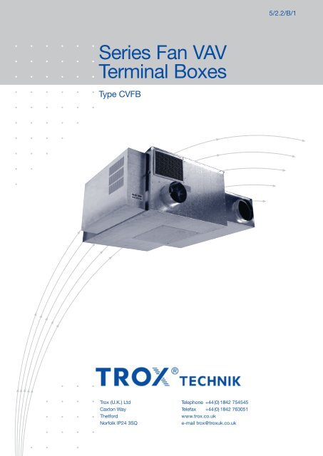
1 Velocity Flowgrid Primary Air<br />
2 Fan/Motor<br />
1<br />
3 Controls Package<br />
4 Air Induction Port<br />
5 Fan Access Opening<br />
6<br />
6 Multi-Outlet Spigot<br />
3<br />
2<br />
5<br />
Trox Series Fan VAV Terminal Boxes take primary and<br />
induction air, mix the two thoroughly and provide a constant<br />
air supply to the occupied zone of the building.<br />
Total flow from the diffuser is kept substantially constant<br />
thus giving very good air distribution even with high turn<br />
down of the primary air volume. The primary air damper can<br />
be fully shut.<br />
Trox Series Fan VAV Terminal Boxes have been designed<br />
and developed to achieve lower room noise levels.<br />
Discharge and case radiated sound pressure levels of NR<br />
35 can be achieved in the occupied zone.<br />
Pressure independent control of the primary VAV damper is<br />
accomplished by use of a Multi-point flowgrid which gives<br />
accurate control of air flow even with a 90° bend on the<br />
inlet spigot.<br />
Mixing between the primary airstream and the induced<br />
warm air from the ceiling void is by forward curved blade<br />
centrifugal fan with a direct drive motor. This direct drive<br />
motor is of the permanent split capacitor type, eminently<br />
suitable for use with stepless fan speed controllers.<br />
2
Construction · Dimensions · Materials<br />
Trox Series Fan VAV Boxes save energy by utilising the<br />
warm air in the building already generated by other sources<br />
and mixing it with primary air before distributing a constant<br />
volume air supply direct to the occupied zone. This reduces<br />
energy consumption, so providing long term operational<br />
savings. Trox Series Fan VAV boxes are suitable for pneumatic<br />
or electronic control. Volume flow tolerance is dependent<br />
on the type of control system but is typically ±5% to<br />
±10% of set volume.<br />
The units are designed for use in VAV systems and in conjunction<br />
with DDC controllers permit communications between<br />
the boxes and a centralised control area.<br />
General<br />
Series Fan VAV terminal VAV boxes are constructed from<br />
galvanised steel meeting all relevant UK construction standards.<br />
All electrical control components are protected by<br />
sheet metal enclosures to meet UK practices. The enclosure<br />
has a single electrical (230 V or 400 V) mains entry position.<br />
Casing<br />
The casing is sturdily constructed of galvanised sheet steel.<br />
The overall construction is reinforced to meet acoustic performance<br />
requirements.<br />
- Casing with acoustic and thermal insulation, erosion resistant<br />
up to 20 m/s.<br />
- High pressure side with duct spigot suitable for circular<br />
ducting.<br />
- Low pressure side suitable for angle frames or slide-on<br />
flanges (type FDS outlet) or fitted outlet box.<br />
- Casing leakage rate to DW 144 Class A.<br />
- Drilled mounting holes for support rods are provided in the<br />
top flange of the casing.<br />
- Outlet plenum available (type 20B or 20C).<br />
<strong>Type</strong> <strong>CVFB</strong> - ER with Internal Electric Heater<br />
<strong>CVFB</strong> Outlet Size Spigot mm D dia mm Weight kg<br />
210 160, 200 1mm smaller than spigot size 73<br />
3
Construction · Dimensions · Materials<br />
Access Door<br />
To avoid removal of the terminal box once fitted in the<br />
system, an access door is provided in the casing underside<br />
so that the fan/motor can be serviced, or in the unlikely<br />
event of failure, removed without disturbing the duct<br />
connections.<br />
Insulation<br />
- The inside of the terminal box is acoustically lined with a<br />
PU foam.<br />
- The access door is also lined with the same material.<br />
- All lining materials have Class ‘O’ fire rating conforming to<br />
UK building regulations.<br />
VAV Section – Volume Flow<br />
The Series Fan VAV Terminal Box is suitable for pressure<br />
independent control. Volume flow is sensed by a multi-point,<br />
averaging flowgrid measuring pressure differential.<br />
- Primary volume flow tolerance is dependent on type of<br />
control system but is typically ±5% to ±10% of set volume.<br />
- Primary volume flow control range typically 100% to 15%<br />
depending on type of control.<br />
- Free issue electronic controllers can be fitted.<br />
- Primary air volume flow range adjustment at factory.<br />
- Volume measurement can be made on site using the flowgrid;<br />
also adjustment of volume flow through controller.<br />
- Control and full shut off is achieved with a single damper.<br />
<strong>Type</strong> <strong>CVFB</strong> - ER - FDS (Details of <strong>CVFB</strong> - 1R LPHW heater on request)<br />
<strong>CVFB</strong> Outlet Size Spigot mm D dia mm Weight kg<br />
210 160, 200 1mm smaller than spigot size 75<br />
4
Construction · Dimensions · Materials<br />
Pressure Differential Flowgrid<br />
- Minimum pressure differential signal from 2Pa upwards.<br />
- Sensor tubes in aluminium.<br />
- Test pressure tappings are supplied with tight fitting caps.<br />
- Calibration graphs and constants are provided to relate<br />
volume flow in litres/second to the measured pressure differentials.<br />
- The differential pressure generated by the averaging sensor<br />
is within ±3% of the calibration chart value over the<br />
range of typical primary air flow rates.<br />
Control Damper<br />
The single blade damper is mounted in the circular duct<br />
behind the flow measuring grid. The drive spindle is extended<br />
through the casing and a suitable actuator slips over<br />
the shaft and locks directly to it.<br />
- The closed damper has a shut off leakage at 500Pa inlet<br />
pressure of less than 0.5% of rated flow.<br />
- The damper blade is positively connected to its drive shaft<br />
which runs in maintenance free plastic (Pocan) long life<br />
bearings.<br />
- Evoprene damper seal, thermoplastic elastomer compound<br />
seal suitable for temperatures up to 50°C.<br />
<strong>Type</strong> <strong>CVFB</strong> - EX with External Electric Heater<br />
D<br />
Note 1) = Outlet fixing hole CTRS = opening + 34mm<br />
<strong>CVFB</strong> Outlet Size Spigot mm D dia mm Weight kg<br />
110 160<br />
1mm smaller<br />
77<br />
210 160, 200<br />
than spigot size<br />
80<br />
5
Construction · Dimensions<br />
<strong>Type</strong> <strong>CVFB</strong> - * - 20B<br />
258<br />
6
Construction · Dimensions · Materials<br />
<strong>Type</strong> <strong>CVFB</strong> - * - 20C<br />
7
Aerodynamic Data<br />
Primary Air Volume Range · Fan Volumes<br />
Performance Details<br />
- Discharge flow remains constant within ±7.5% from 100%<br />
primary to minimum primary air.<br />
- Minimum primary air pressure differential required typically<br />
25Pa. For actual values see page 9.<br />
Notes<br />
The minimum primary air volume shown is the minimum factory<br />
set value for control purposes. See page 9 for leakage<br />
on full shut off.<br />
Fan volume is given for typical downstream pressures. Other<br />
downstream pressures duties available on request.<br />
Primary Air Volume Range<br />
Spigot Spigot Minimum* Maximum<br />
Code Size Primary Primary<br />
Airflow (l/s) Airflow (l/s)<br />
160 159 30 180<br />
200 199 50 260<br />
Table 1: Fan Volume <strong>CVFB</strong>-ER and <strong>CVFB</strong>-EX<br />
<strong>CVFB</strong> Size Fan Code Fan Speed Total Fan Volume<br />
ESP1) 50Pa (l/s)<br />
110 8<br />
210 2<br />
Min 100<br />
Max 140<br />
Min 160<br />
Max 230<br />
1) ESP = External Static Pressure<br />
Selection Method<br />
- First select case size and fan code on basis of fan volume<br />
flow rate.<br />
- Select inlet spigot size to meet maximum and minimum<br />
primary air requirements.<br />
Example<br />
Given Fan flow 180 l/s ESP 50 Pa<br />
Maximum Primary Air 120 l/s<br />
Minimum Primary Air 35 l/s<br />
Selection<br />
Spigot Code 160<br />
Fan Code 2<br />
Case Size 210<br />
8
Aerodynamic Data<br />
Minimum Inlet Static Pressure · Closed Primary Air Damper Leakage<br />
Table 3: Minimum Inlet Static Pressure<br />
Primary Inlet<br />
Spigot Code<br />
V I (l/s) p<br />
. SI min Pa<br />
160<br />
200<br />
30 20<br />
180 40<br />
50 20<br />
260 35<br />
Table 4: Leakage Across Closed Primary Air Damper<br />
.<br />
V<br />
Primary<br />
L (l/s)<br />
Inlet<br />
Spigot<br />
p.<br />
SI Pa<br />
Code<br />
250 500<br />
160 0.20 0.28<br />
200 0.31 0.44<br />
9
Technical Data · Accessories<br />
Fan and Motor<br />
The Series Fan VAV terminal boxes are fitted with fan<br />
casings (Scrolls) manufactured from sheet steel.<br />
The fans have a forward curved fan impeller.<br />
All fan motors are direct drive resiliently mounted via location<br />
brackets suitable for 230 volts 50 Hz single phase and<br />
are supplied with auto reset thermal overloads.<br />
The fan motors are permanent split capacitor types fitted<br />
with permanently lubricated bearings.<br />
All earthing wiring and component selection conforms to<br />
BS/IEE wiring requirements.<br />
Fan Motor Speed Control<br />
All fan motors fitted to Trox Series Fan VAV Terminal Boxes<br />
are suitable for fan speed control.<br />
Supplied as standard is a manually adjusted solid state Triac<br />
based fan speed controller which provides stepless adjustable<br />
fan speed – from maximum to minimum. The system is<br />
matched to the motor and includes minimum voltage limits<br />
to ensure stable motor operation.<br />
Table 5: Fan Motor Details<br />
Fan Code W 2 watts W 1 watts A R amps A S amps<br />
2 120 275 1.2 2.8<br />
8 40 100 0.43 0.63<br />
Power factor: 0.9 approx.<br />
10
Nomenclature<br />
Nomenclature<br />
L WNR : NR rating of octave sound power levels for ductborne regenerated noise.<br />
NR 1 : NR rating of octave sound power levels of ductborne regenerated noise including<br />
insertion loss of TSFB secondary silencer and 8 dB room attenuation.<br />
NR 2 : NR rating of octave sound power levels for case radiation and induction port<br />
noise including a combined 14 dB ceiling reduction and room attenuation, for<br />
the case of zero primary air (fan only).<br />
NR 3 : NR rating of octave sound power levels for case radiation and induction port<br />
noise including a combined 14 dB ceiling reduction and room attenuation, for<br />
the case of 100% primary air and 200 Pa primary air pressure.<br />
p.<br />
SD in Pa: Downstream static pressure.<br />
p<br />
. SI in Pa: Inlet static pressure.<br />
p<br />
. SI min in Pa: Minimum inlet static pressure.<br />
V I in l/s: Primary air volume flow rate.<br />
.<br />
V D in l/s: Discharge (fan)volume flow rate.<br />
V L in l/s: Leakage volume flow rate across closed primary air damper.<br />
W 1 in Watts: Input power to motor at maximum fan volume flow rate.<br />
W.<br />
2 in Watts: Output power of motor.<br />
A.<br />
S in amps: Motor starting current.<br />
A R in amps: Motor running current.<br />
M W in kg/s: Mass flow water.<br />
Q in kW: Heat output.<br />
∆p W in kPa: Water pressure drop.<br />
11
Quick Selection<br />
Table 6: Quick selection (Guide Figures)<br />
.<br />
<strong>CVFB</strong><br />
V<br />
Fan Code<br />
D p SD LWNR NR1 NR2 NR3<br />
Outlet Size l/s Pa<br />
110 8<br />
210 2<br />
100 50 53 30 17 24<br />
140 50 56 33 20 26<br />
160 50 53 28 28 25<br />
230 50 58 33 29 29<br />
Refer to table on page 8 for relationship of inlet spigot diameter and primary air flow rate.<br />
Sound Power Level spectrum available on request.<br />
For NR30 rooms, it is recommended that the -AR- attenuated return is used (with EX heater if required).<br />
12
Secondary Attenuator<br />
TSFB<br />
Insulation<br />
- The inside of the TSFB Attenuator is acoustically lined with<br />
a minimum 50mm thickness.<br />
- Face of the mineral wool has a glass fibre tissue covering<br />
securely fixed to the substrate. PU Foam side liners are<br />
incorporated.<br />
- All lining materials have Class ‘O’ fire rating conforming to<br />
UK building regulations.<br />
- A perforated plate liner is available on request.<br />
Secondary Attenuator <strong>Type</strong> TSFB<br />
Table 7:<br />
<strong>CVFB</strong> Outlet Size L B H N M X<br />
110 750 354 392 284 237 170<br />
210 1000 454 402 384 288 175<br />
13
Water Coil Output Data<br />
Hot Water Coils<br />
The hot water heating coil is manufactured from 3 /8<br />
inch diameter copper tube with aluminium fins spaced<br />
at 1.8mm. The tubes are formed into circuits to limit<br />
water velocity and mounted in a galvanised sheet steel<br />
flanged frame with copper headers. The heating coils<br />
meet the requirements of British Standards/Codes as<br />
applicable. Coil connections are 1 /2 inch BSP as standard.<br />
Plugged air vent and drain points are provided.<br />
Water control valves can be supplied as a loose item if<br />
required.<br />
The maximum coil output is shown in kW for water<br />
temperatures of 82°C flow and 71°C return and based<br />
on air temperature entering the coil of 22°C. The water<br />
pressure drop is shown in kPa and the water rate in<br />
kg/s. Other water/air temperatures available on<br />
request.<br />
Table 8: One Row Coil<br />
<strong>CVFB</strong> Outlet<br />
.<br />
V D<br />
.<br />
Q<br />
.<br />
M W ∆p W<br />
Size l/s kW kg/s kPa<br />
110<br />
210<br />
100 2.2 .052 3<br />
125 2.6 .062 5<br />
165 3.8 .090 2<br />
220 4.4 .105 3<br />
14
Electric Heater Data<br />
Electric Heaters 1)<br />
The electric heater is available as an integral unit complete<br />
with controls including fuses and interlocks. The<br />
integral air heater has elements designed for black heat<br />
operation and consists of 80/20 nickel chrome wire in a<br />
stainless steel tube (grade 312) filled with magnesium<br />
oxide.<br />
An automatic reset high temperature cut out is fitted<br />
and a brass earth stud included. The heater is manufactured<br />
to British Standards/Codes as applicable and<br />
fully factory tested. A low air pressure switch is fitted on<br />
type EX. On type ER a velocity switch is used.. This<br />
switch will disconnect the heater if the fan stops. The<br />
heater elements are wired back into the control enclosure,<br />
including the earth, and heater fuses can be supplied.<br />
Control of the heater can be arranged for stepless control<br />
by thyristors. Control type should be selected to<br />
suit the temperature controller used and the degree of<br />
accuracy required on temperature control.<br />
1) Electric heaters are available on request.<br />
Full details required such as kW, Voltage,<br />
Phase should be stated.<br />
Note: type ER heaters are only suitable for heating at minimum primary<br />
air volume.<br />
When heating is required at maximum primary air, e.g for meeting<br />
rooms, use type EX.<br />
Table 9: Electric Heaters<br />
<strong>CVFB</strong><br />
Outlet<br />
Size<br />
230V / 1ph 50Hz<br />
.<br />
Q kW<br />
Supply Voltage<br />
<strong>Type</strong><br />
110 1.0 EX<br />
210 1.0 or 1.5 ER<br />
210 1, 2 or 3 EX<br />
15
Order Details<br />
Specification Text<br />
Series Fan VAV boxes type <strong>CVFB</strong> for constant room air supply<br />
volume combined with VAV primary air control having<br />
high turndown by use of a multi-point flowgrid. Induction of<br />
warm air from the ceiling void by forward curved blade centrifugal<br />
fan with direct drive motor.<br />
Single blade control damper with seal for shut off. Stepless<br />
speed controller to enable fan duty to be set to match the<br />
downstream duct system pressure.<br />
Materials<br />
Casing manufactured from galvanised sheet steel.<br />
Internally lined with PU Foam.<br />
Multi-point flowgrid construced from aluminium tubes.<br />
Fan casing manufactured from sheet steel. Fan impeller<br />
from aluminium alloy.<br />
Order Code<br />
<strong>CVFB</strong> - ER - - - 20B<br />
/ 210 x 200 x 2 / BC0 / EO - 180 - 170 - 50 / ******<br />
<strong>Type</strong><br />
Outlet<br />
Size<br />
Reheat<br />
110<br />
ER = internal electric heater 5)<br />
210<br />
EX = external electric heater<br />
1R = LPHW coil (1 row)<br />
or no entry<br />
Attenuated<br />
Return 2)<br />
AR<br />
or no entry<br />
Outlet<br />
20B Integral Outlet Box 1) 2 outlet<br />
FDS Flanged Duct Section 3)<br />
20C Integral Outlet Box 4) 4 outlet<br />
or no entry<br />
Spigot<br />
Size<br />
160<br />
200<br />
Fan<br />
Code<br />
2<br />
8<br />
Controller/<br />
Actuator<br />
Refer to Trox<br />
E0 = Control Signal 0-10 V dc<br />
for standard BCO<br />
controller/actuator<br />
Control<br />
Diagram<br />
Refer to Trox<br />
Minimum primary l/s<br />
Maximum primary l/s<br />
Fan volume l/s<br />
Notes<br />
1)<br />
With 198mm dia spigots (2 off) Not available with ‘EX’ external reheat or LPHW coil<br />
2)<br />
Not available with ER reheat<br />
3)<br />
Not available with EX reheat. Required with LPHW coil<br />
4)<br />
With 198mm dia spigots (4 off). Not available with ‘EX’ external electric reheat or LPHW coil<br />
5)<br />
Not available on size 110<br />
Design changes reserved · All rights reserved © Trox (U.K.) Limited (01/2005)<br />
16<br />
Order Code - Secondary Silencer<br />
Product <strong>Type</strong><br />
TSFB - LB - VGR - D1 / 210 / 0 /<br />
Lining<br />
LB = Perforated plate lining<br />
or no entry<br />
Flowgrid<br />
VGL = Left Hand<br />
VGR = Right Hand<br />
or no entry<br />
Duct Piece<br />
D1 = Additional ducts fitted<br />
or no entry<br />
Size<br />
110<br />
210<br />
Not used<br />
Order Example<br />
No entry for standard length<br />
or special length in mm on request<br />
Make : <strong>TROX</strong><br />
<strong>Type</strong> : <strong>CVFB</strong>-ER-20B/210x200x2/BC0/EO-180-170-50<br />
COMPLETE WITH 1KW HEATER