

15GCSX Packaged Unit Installation Manual - Lennox
15GCSX Packaged Unit Installation Manual - Lennox
15GCSX Packaged Unit Installation Manual - Lennox

You also want an ePaper? Increase the reach of your titles
YUMPU automatically turns print PDFs into web optimized ePapers that Google loves.
Cooling Start−Up<br />
The cooling section is a complete factory package utilizing<br />
an air−cooled condenser. The system is factory−charged<br />
with HFC−410A refrigerant. The compressor is<br />
hermetically sealed, internally sprung and base−mounted<br />
with rubber−insolated hold−down bolts.<br />
Pre−Start Check List:<br />
1 − Make sure refrigerant lines do not rub against the<br />
cabinet or each other.<br />
2 − Inspect all electrical wiring, both factory− and<br />
field−installed, for loose connections.<br />
3 − Check voltage at the disconnect switch. Voltage must<br />
be within the range listed on the unit nameplate. If not,<br />
consult power company and have voltage condition<br />
corrected before starting unit.<br />
4 − Recheck voltage with unit running. If power is not<br />
within the range listed on the unit nameplate, stop the<br />
unit and consult the power company. Check unit<br />
amperage. Refer to unit nameplate for correct running<br />
amps.<br />
5 − Make sure filter is in place before unit start−up.<br />
Cooling Sequence of Operation<br />
When the thermostat calls for cooling, R" is closed to G"<br />
and Y" (figure 11). This completes the low voltage control<br />
circuit, energizing the compressor, condenser fan motor<br />
and blower motor.<br />
NOTE − At the start of the each cooling demand, the<br />
combustion air blower (draft motor) will operate for 10<br />
seconds.<br />
<strong>Unit</strong> compressors have internal protection. If there is an<br />
abnormal rise in the compressor temperature, the<br />
protector will open and the compressor will stop.<br />
Blower Delay − Cooling<br />
In the cooling mode, the circulating air blower operation is<br />
delayed for 5 seconds after the compressor starts. The<br />
blower continues to operate for 90 seconds after the<br />
compressor is de−energized.<br />
NOTE − With the proper thermostat and subbase,<br />
continuous blower operation is possible by closing the R to<br />
G circuit. Cooling blower delay is also functional in this<br />
mode.<br />
System Performance<br />
This self−contained system has been factory−charged for<br />
optimal performance. If performance is questionable, use<br />
the following procedure to check the system.<br />
Ensure that unit has been installed per these instructions<br />
and that line voltage and air flow are both correct. Check<br />
subcooling values by measuring pressure at the liquid line<br />
(high side) service port. Measure liquid line temperature<br />
within 2 inches of the service port connection to its main<br />
tube. If subcooling measured deviates from values in table<br />
7 by more than 2 degrees F, check internal seals, service<br />
panels and duct system for air leaks, as well as restrictions.<br />
Also check blower speed settings. Make all necessary<br />
adjustments. If unit performance remains questionable,<br />
recover unit refrigerant charge, evacuate to 500 Microns,<br />
and weigh in refrigerant to match value given on unit<br />
nameplate. It is critical that exact required charge is used.<br />
Failure to follow this instruction will compromise system<br />
performance. If unit performance is still questionable,<br />
check for blocked coil or circuits, malfunctioning metering<br />
devices or other system component problems.<br />
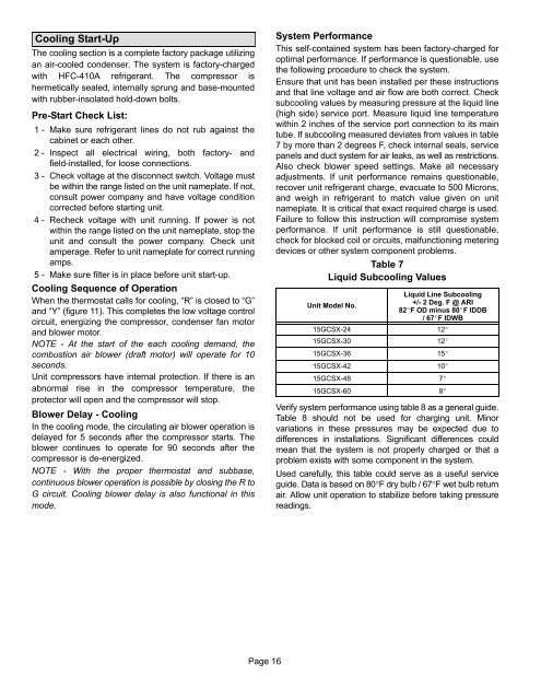
Table 7<br />
Liquid Subcooling Values<br />
<strong>Unit</strong> Model No.<br />
<strong>15GCSX</strong>−24<br />
<strong>15GCSX</strong>−30<br />
<strong>15GCSX</strong>−36<br />
<strong>15GCSX</strong>−42<br />
<strong>15GCSX</strong>−48<br />
<strong>15GCSX</strong>−60<br />
Liquid Line Subcooling<br />
+/− 2 Deg. F @ ARI<br />
82F OD minus 80F IDDB<br />
/ 67F IDWB<br />
Verify system performance using table 8 as a general guide.<br />
Table 8 should not be used for charging unit. Minor<br />
variations in these pressures may be expected due to<br />
differences in installations. Significant differences could<br />
mean that the system is not properly charged or that a<br />
problem exists with some component in the system.<br />
Used carefully, this table could serve as a useful service<br />
guide. Data is based on 80F dry bulb / 67F wet bulb return<br />
air. Allow unit operation to stabilize before taking pressure<br />
readings.<br />
12<br />
12<br />
15<br />
10<br />
7<br />
8<br />
Page 16


