

INSTALLATION INSTRUCTIONS - Lennox
INSTALLATION INSTRUCTIONS - Lennox
INSTALLATION INSTRUCTIONS - Lennox

Create successful ePaper yourself
Turn your PDF publications into a flip-book with our unique Google optimized e-Paper software.
Air from Outside<br />
If air from outside is brought in for combustion and ventilation,<br />
the confined space shall be provided with two permanent<br />
openings. One opening shall be within 12" (305 mm)<br />
of the top of the enclosure and one within 12" (305 mm) of<br />
the bottom. These openings must communicate directly or<br />
by ducts with the outdoors or spaces (crawl or attic) that<br />
freely communicate with the outdoors or indirectly through<br />
vertical ducts. Each opening shall have a minimum free<br />
area of 1 square inch (6.4 square centimeters) per 4,000<br />
Btu (1172 W) per hour of total input rating of all equipment<br />
in the enclosure. (See figure 4.) When communicating with<br />
the outdoors through horizontal ducts, each opening shall<br />
have a minimum free area of 1 square inch (6.4 square<br />
centimeters) per 2,000 Btu (586 W) per total input rating of<br />
all equipment in the enclosure (See figure 5).<br />
Equipment In Confined Space<br />
All Air From Outside<br />
(Inlet Air from Crawl Space and Outlet Air to<br />
Ventilated Attic)<br />
Chimney or<br />
Oil Vent<br />
Oil<br />
Furnace<br />
Ventilation Louvers<br />
(Each End Of Attic)<br />
Outlet<br />
Air<br />
Water<br />
Heater<br />
Oil<br />
Furnace<br />
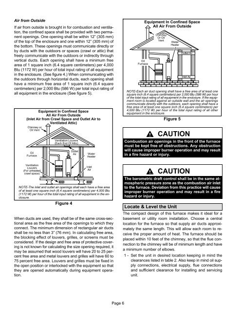
Equipment In Confined Space<br />
All Air From Outside<br />
Chimney<br />
Or Oil<br />
Vent<br />
Water<br />
Heater<br />
Outlet Air<br />
Inlet Air<br />
NOTE−Each air duct opening shall have a free area of at least one<br />
square inch (6.4 square centimeters) per 2,000 Btu (586 W) per hour<br />
of the total input rating of all equipment in the enclosure. If the equipment<br />
room is located against an outside wall and the air openings<br />
communicate directly with the outdoors, each opening shall have a<br />
free area of at least one square inch (6.4 square centimeters) per<br />
4,000 Btu (1172 W) per hour of the total input rating of all other<br />
equipment in the enclosure.<br />
Figure 5<br />
CAUTION<br />
Combustion air openings in the front of the furnace<br />
must be kept free of obstructions. Any obstruction<br />
will cause improper burner operation and may result<br />
in a fire hazard or injury.<br />
Ventilation<br />
Louvers<br />
(For unheated<br />
crawl space)<br />
Inlet<br />
Air<br />
NOTE−The inlet and outlet air openings shall each have a free area<br />
of at least one square inch (6.4 square centimeters) per 4,000 Btu<br />
(1172 W) per hour of the total input rating of all equipment in the enclosure.<br />
Figure 4<br />
When ducts are used, they shall be of the same cross−sectional<br />
area as the free area of the openings to which they<br />
connect. The minimum dimension of rectangular air ducts<br />
shall be no less than 3" (76 mm). In calculating free area,<br />
the blocking effect of louvers, grilles, or screens must be<br />
considered. If the design and free area of protective covering<br />
is not known for calculating the size opening required, it<br />
may be assumed that wood louvers will have 20 to 25 percent<br />
free area and metal louvers and grilles will have 60 to<br />
75 percent free area. Louvers and grilles must be fixed in<br />
the open position or interlocked with the equipment so that<br />
they are opened automatically during equipment operation.<br />
CAUTION<br />
The barometric draft control shall be in the same atmospheric<br />
pressure zone as the combustion air inlet<br />
to the furnace. Deviation from this practice will cause<br />
improper burner operation and may result in a fire<br />
hazard or injury.<br />
Locate & Level the Unit<br />
The compact design of this furnace makes it ideal for a<br />
basement or utility room installation. Choose a central<br />
location for the furnace so that supply air ducts approximately<br />
the same length. This will allow each room to receive<br />
the proper amount of heat. The furnace should be<br />
placed within 10 feet of the chimney, so that the flue connection<br />
to the chimney will be of minimum length and have<br />
a minimum number of elbows.<br />
1 − Set the unit in desired location keeping in mind the<br />
clearances listed in table 2. Also keep in mind oil supply<br />
connections, electrical supply, flue connections<br />
and sufficient clearance for installing and servicing<br />
unit.<br />
Page 6


