Compact double U-Slots Patch Antenna for Mobile Wimax ...
Compact double U-Slots Patch Antenna for Mobile Wimax ...
Compact double U-Slots Patch Antenna for Mobile Wimax ...

Create successful ePaper yourself
Turn your PDF publications into a flip-book with our unique Google optimized e-Paper software.
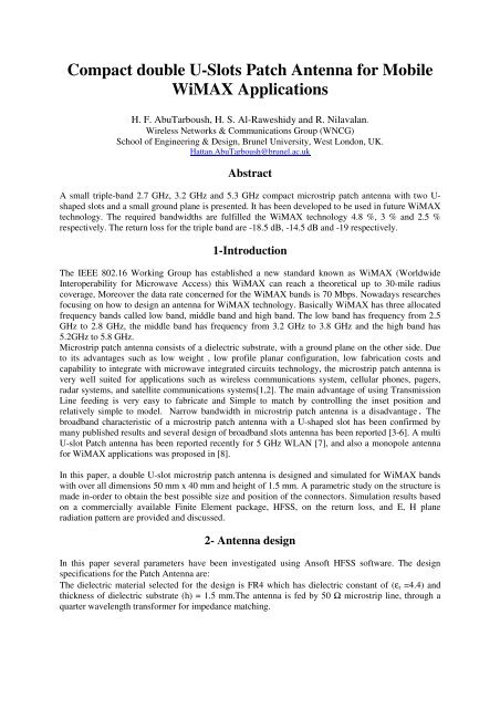
<strong>Compact</strong> <strong>double</strong> U-<strong>Slots</strong> <strong>Patch</strong> <strong>Antenna</strong> <strong>for</strong> <strong>Mobile</strong><br />
WiMAX Applications<br />
H. F. AbuTarboush, H. S. Al-Raweshidy and R. Nilavalan.<br />
Wireless Networks & Communications Group (WNCG)<br />
School of Engineering & Design, Brunel University, West London, UK.<br />
Hattan.AbuTarboush@brunel.ac.uk<br />
Abstract<br />
A small triple-band 2.7 GHz, 3.2 GHz and 5.3 GHz compact microstrip patch antenna with two Ushaped<br />
slots and a small ground plane is presented. It has been developed to be used in future WiMAX<br />
technology. The required bandwidths are fulfilled the WiMAX technology 4.8 %, 3 % and 2.5 %<br />
respectively. The return loss <strong>for</strong> the triple band are -18.5 dB, -14.5 dB and -19 respectively.<br />
1-Introduction<br />
The IEEE 802.16 Working Group has established a new standard known as WiMAX (Worldwide<br />
Interoperability <strong>for</strong> Microwave Access) this WiMAX can reach a theoretical up to 30-mile radius<br />
coverage, Moreover the data rate concerned <strong>for</strong> the WiMAX bands is 70 Mbps. Nowadays researches<br />
focusing on how to design an antenna <strong>for</strong> WiMAX technology. Basically WiMAX has three allocated<br />
frequency bands called low band, middle band and high band. The low band has frequency from 2.5<br />
GHz to 2.8 GHz, the middle band has frequency from 3.2 GHz to 3.8 GHz and the high band has<br />
5.2GHz to 5.8 GHz.<br />
Microstrip patch antenna consists of a dielectric substrate, with a ground plane on the other side. Due<br />
to its advantages such as low weight , low profile planar configuration, low fabrication costs and<br />
capability to integrate with microwave integrated circuits technology, the microstrip patch antenna is<br />
very well suited <strong>for</strong> applications such as wireless communications system, cellular phones, pagers,<br />
radar systems, and satellite communications systems[1,2]. The main advantage of using Transmission<br />
Line feeding is very easy to fabricate and Simple to match by controlling the inset position and<br />
relatively simple to model. Narrow bandwidth in microstrip patch antenna is a disadvantage. The<br />
broadband characteristic of a microstrip patch antenna with a U-shaped slot has been confirmed by<br />
many published results and several design of broadband slots antenna has been reported [3-6]. A multi<br />
U-slot <strong>Patch</strong> antenna has been reported recently <strong>for</strong> 5 GHz WLAN [7], and also a monopole antenna<br />
<strong>for</strong> WiMAX applications was proposed in [8].<br />
In this paper, a <strong>double</strong> U-slot microstrip patch antenna is designed and simulated <strong>for</strong> WiMAX bands<br />
with over all dimensions 50 mm x 40 mm and height of 1.5 mm. A parametric study on the structure is<br />
made in-order to obtain the best possible size and position of the connectors. Simulation results based<br />
on a commercially available Finite Element package, HFSS, on the return loss, and E, H plane<br />
radiation pattern are provided and discussed.<br />
2- <strong>Antenna</strong> design<br />
In this paper several parameters have been investigated using Ansoft HFSS software. The design<br />
specifications <strong>for</strong> the <strong>Patch</strong> <strong>Antenna</strong> are:<br />
The dielectric material selected <strong>for</strong> the design is FR4 which has dielectric constant of (εr =4.4) and<br />
thickness of dielectric substrate (h) = 1.5 mm.The antenna is fed by 50 Ω microstrip line, through a<br />
quarter wavelength trans<strong>for</strong>mer <strong>for</strong> impedance matching.
Figure 1 configuration of the <strong>double</strong> U-slots <strong>Patch</strong> antenna on a dielectric substrate.<br />
The overall dimensions of the Double U-slot patch are:<br />
L 40 mm<br />
W 50 mm<br />
L2 30 mm<br />
W2 25 mm<br />
La 15 mm<br />
Wa 5 mm<br />
Lb 5 mm<br />
Wb 2.5 mm<br />
Lc 5 mm<br />
Wc 5 mm<br />
Ld 10 mm<br />
Wd 5 mm<br />
Lf 19.59 mm<br />
Wf 2 mm<br />
Table 1: the dimensions of the <strong>Antenna</strong><br />
WiMAX technology has a data rate up to 70 Mbps. Through simulations return loss losses were<br />
calculated with different widths of the connector (As shown in Fig. 1) and the E-Plane and H-Plane<br />
radiation patterns were also simulated as shown in Fig. 2 and Fig. 3.<br />
Figure 2: the Simulation result <strong>for</strong> the <strong>double</strong> U-slot <strong>Antenna</strong>.
Fig. 2 shows response <strong>for</strong> the <strong>double</strong> U-Slot antenna at three bands which they are 2.7 GHz, 3.2 GHz<br />
and 5.3 GHz. The three bands satisfied the bandwidth of the WiMAX technology. The impedance<br />
bandwidth <strong>for</strong> the low band is 4.8 % which satisfy the required bandwidth <strong>for</strong> WiMAX. Also <strong>for</strong> the<br />
middle band the impedance bandwidth is 3 % whereas in the higher band the bandwidth is 2.5 %. The<br />
return losses <strong>for</strong> the three bands are -18.5 dB, -14.5 dB and -19 respectively.<br />
Figure 3a Figure 3b<br />
Figure 3c<br />
Figure 3: (a) E and H Plane Radiation Pattern at 2.7 GHz. (b) at 3.2 GHz. (c) at 5.3 GHz.<br />
3- Conclusion<br />
The triple-band behaviour at 2.7, 3.2 and 5.3 GHZ has been achieved as well as the bandwidth<br />
requirements <strong>for</strong> WiMAX standards 4.8 %, 3 % and 2.5 % respectively. The return loss <strong>for</strong> the triple<br />
band is -18.5 dB, -14.5 dB and -19 dB respectively. Very broad radiation patterns have been obtained<br />
which seems to be adequate <strong>for</strong> the envisaged applications<br />
Acknowledgement<br />
The authors would like to thank Ansoft Company UK <strong>for</strong> their support in HFSS software.
References<br />
[1]W.L. Stutzman and G.A. Thiele, <strong>Antenna</strong> Theory and Design, 2nd ed. New York: Wiley, 1998<br />
[2]C.A. Balanis, <strong>Antenna</strong> Theory, 2nd ed. New York: John Wiley & Sons, Inc., 1997.<br />
[3]K. F. Tong, K.M. Luk,K.F. Lee, and S.M.Shum, “ Analysis of a broadband U-slot microstrip<br />
antenna,” 10 th international conference on <strong>Antenna</strong> and propagation, pp 14-17, April 1997, conference<br />
publication no.436, IEEE 1997.<br />
[4] M. Sanad, “Double C-patch antennas having different aperture shapes,” in Proc. IEEE <strong>Antenna</strong>s<br />
and Propagation Dig., June 1995, pp.2116–2119.<br />
[5] Murad NA. “Microstrip U-shaped dual-band antenna,” Applied Electromagnetic, 2005 APACE<br />
2005 Asia-Pacific Conference on 2005:4 pp.<br />
[6] Hadian AM. “Wideband rectangular microstrip patch antenna with U-slot,” <strong>Antenna</strong>s and<br />
Propagation, 2007 EuCAP 2007 The Second European Conference on. 2007:1-5.<br />
[7] Jeong-Min JU, Gyey-Teak JEONG, Joong-Han YOON, Cheol-Soon KIM, Hyung-Sup KIM, and<br />
Kyung-Sup KWAK, “Design of Multiple U-Shaped Slot<br />
Microstrip <strong>Patch</strong> <strong>Antenna</strong> in 5 GHz Band WLAN,” IEICE Trans B: Communications E88-B: 821-825.<br />
[8] T. liu and L. L. Wong, “A wideband Stubby Monopole <strong>Antenna</strong> and a GPS <strong>for</strong> WiMAX <strong>Mobile</strong><br />
Phone with E911 Function,” Microwave and Optical Technology Letter, Vol 46, 2005, pp. 485-487.