Four Corner - Texas Water Development Board
Four Corner - Texas Water Development Board
Four Corner - Texas Water Development Board

You also want an ePaper? Increase the reach of your titles
YUMPU automatically turns print PDFs into web optimized ePapers that Google loves.
--<br />
June 1, 1999<br />
1420 \X:cst Mockingbird Lane, Suite jOO, Dallas, <strong>Texas</strong> 75247-4906<br />
Mr. Curtis Johnson, P.E.<br />
Technical Coordinator<br />
1700 N. Congress Ave., Rm. 461<br />
Austin, TX 78711-3231<br />
Re: <strong>Four</strong> <strong>Corner</strong>s Area Regional Planning Study<br />
TWDB Contract No. 97-483-206<br />
Dear Mr. Johnson:<br />
Telephone<br />
In accordance with our agreement, enclosed please find 9 copies of our Final Report 2 ,<br />
4 _ 6 3 o _ 8 8 6 7<br />
and one unbound copy in accordance with our agreement. Should you have any<br />
comments or questions regarding the transmittal of this report please do not hesitate<br />
Facsimile<br />
to call me at 214-630-8867.<br />
Very truly yours,<br />
Earth Tech, Inc.<br />
Joe W. Ezzell, P.E.<br />
Project Manager<br />
Ms. Marilynn Kindell, Fort Bend Co. 3 copies<br />
Ernesto Abila, <strong>Four</strong> <strong>Corner</strong>s WSC, 2 copies<br />
Mark Loethen, P.E., Pate Engineers<br />
Charles Gooden, P.E., Gooden Consulting<br />
-<br />
EARTH@T E C H<br />
A 'tqcD INTERNAnONAL LTD. COMPANY
FINAL REPORT<br />
....<br />
G.l<br />
c:<br />
ctl<br />
c.<br />
...<br />
0<br />
-<br />
.c<br />
(.)<br />
CD<br />
I ,<br />
WATER AND<br />
WASTEWATER FACILITIES<br />
PLANNING STUDY<br />
FOR<br />
THE FOUR CORNERS AREA<br />
»<br />
Cl<br />
0<br />
0<br />
c:<br />
..c:<br />
(J<br />
G.l<br />
....<br />
c:<br />
ctl<br />
Cl<br />
c:<br />
...<br />
G.l<br />
G.l<br />
c:<br />
Cl<br />
c:<br />
G.l<br />
OF<br />
FORT BEND COUNTY,<br />
TEXAS<br />
Prepared by:<br />
Earth Tech<br />
with<br />
Pate Engineers<br />
Goodsen Consulting Engineers<br />
BC&AD Archaeology<br />
HVJ Associates<br />
TWDB CONTRACT No. 97-483-206<br />
MAY 1999
FINAL REPORT<br />
....<br />
(I)<br />
c<br />
ctl<br />
a.<br />
(I)<br />
..s::::<br />
....<br />
...<br />
0<br />
-<br />
-'=<br />
(.)<br />
(I)<br />
I ,<br />
WATER AND<br />
WASTEWATER FACILITIES<br />
PLANNING STUDY<br />
FOR<br />
THE FOUR CORNERS AREA<br />
><br />
Cl<br />
0<br />
0<br />
c<br />
..s::::<br />
-(.)<br />
(I)<br />
...<br />
(I)<br />
(I)<br />
c<br />
Cl<br />
c<br />
(I)<br />
OF<br />
FORT BEND COUNTY,<br />
TEXAS<br />
Prepared by:<br />
Earth Tech<br />
with<br />
Pate Engineers<br />
Goodsen Consulting Engineers<br />
BC&AD Archaeology<br />
HVJ Associates<br />
TWDB CONTRACT No. 97-483-206<br />
__..... ,,,,,<br />
--:if. OF t, \\<br />
;..._........... E'-t: '•<br />
; , -.,...-......:f.,.•·<br />
"*·' \•I<br />
"*' ..•......•.................\*l<br />
,.... ~<br />
,<br />
~ JOE W. EZZELL ~<br />
l'"'\ ........................... ~<br />
\~\. ~ 6«91 ~ i$}<br />
f{,~>.;;.;:~t;ISTf.';~·~~<br />
'""V~ ••······~ ~v ,.<br />
\.._!OitA\. ~--<br />
_,,....,..,,-<br />
C)t4Jj;d<br />
5-19-99<br />
MAY 1999
FINAL REPORT<br />
WATER AND<br />
WASTEWATER FACILITIES<br />
PLANNING STUDY<br />
FOR<br />
THE FOUR CORNERS AREA<br />
OF<br />
FORT BEND COUNTY,<br />
TEXAS<br />
Prepared by:<br />
Earth Tech<br />
with<br />
Pate Engineers<br />
Goodsen Consulting Engineers<br />
BC&AD Archaeology<br />
HVJ Associates<br />
TWDB CONTRACT No. 97-483-206<br />
__...., ....,,,<br />
......,.,...<br />
--:1E. OF 7"~ \\<br />
lliii:-t: '•<br />
*<br />
:_t\.~·········..<br />
,; c,<br />
........ \.,<br />
'*' ,,. ...<br />
t···························~····~<br />
i1! JOE W. EZZELL i!:<br />
i!'"·<br />
..····························l<br />
\~\ ~ 64491 ~ i~J<br />
'l',.;;..'f.a,stt':":.·:'JY<br />
,,...r.t ........-<br />
.f<br />
~~"' -<br />
\ ..<br />
_,.,.,__...,<br />
!OIIA.\.. ~---<br />
C)«4Jjr
<strong>Four</strong> Comers Area Planning Report Table of Contents<br />
1.0 PLANNING AREA 1-1<br />
1.1. GOALS OF PLANNING STUDY 1-1<br />
1.2. EXISTING DEVELOPMENT 1-3<br />
1.3. AREA SOIL CONDITIONS 1-4<br />
1.4. POPULATION- EXISTING AND PROJECTED 1-5<br />
1.5. EXISTING/PROJECTED WATER AND SEWER DEMANDS 1-6<br />
1.6. ASSESSED VALUES 1-7<br />
2.0 AREA ENVIRONMENTAL ASSESSMENT 2-1<br />
2.1. EVALUATION OF AREA'S HISTORIC LAND USAGE 2-1<br />
2.2. EVALUATION OF AREA'S POTENTIAL WETLANDS 2-2<br />
2.3. DESCRIPTION OF AREA'S POTENTIAL HISTORIC SITES 2-6<br />
2.4. EVALUATION OF AREA'S POTENTIAL ENDANGERED SPECIES HABITATS 2-12<br />
2.5. EXTENT OF FLOOD PLAIN IN AREA 2-13<br />
3.0 SITEEVALUATIONEXISTINGPRIVATE WELLS AND SEPTIC SYSTEMS 3-1<br />
4.0 PROJECT JUSTIFICATION 4-1<br />
4.1. EXISTING CONDITIONS 4-1<br />
4.2. DISCUSSION OF HISTORY OF HEALTH VIOLATIONS 4-1<br />
5.0 ALTERNATIVE WATER AND WASTEWATER SYSTEMS 5-1<br />
5.1. CHEMICAL ANALYSIS- ADJACENT PUBLIC WATER WELLS 5-1<br />
5.2. AREA HYDROGEOLOGIC CONDITIONS AND<br />
GENERAL SOIL GROUNDWATER CHARACTERISTICS<br />
5-1<br />
5.3. WATER AND WASTEWATER SYSTEM REQUIREMENTS<br />
5-2<br />
5.4. ALTERNATIVE SYSTEM LAYOUTS<br />
5-5<br />
5.5. ALTERNATIVE SYSTEMS COSTS<br />
5-7<br />
FINAL REPORT
<strong>Four</strong> <strong>Corner</strong>s Area Planning Report Table of Contents<br />
6.0 AREA WATER AND WASTEWATER SYSTEM RECOMMENDATION<br />
6-1<br />
6.1. WATER AND WASTEWATER SYSTEM LAYOUT<br />
6-1<br />
6.2. WATER SUPPLY AND WASTEWATER TREATMENT PLANT REQUIREMENTS 6-2<br />
6.3. SYSTEM HYDRAULICS AND PUMPING REQUIREMENTS 6-4<br />
6.4. PERMITTING REQUIREMENTS<br />
6-5<br />
6.5. RIGHT-OF-WAY AND REQUIREMENTS<br />
6-6<br />
7.0 OPERATIONAL COSTS<br />
7-1<br />
8.0 WATER CONSERVATION AND DROUGHT MANAGEMENT PLAN<br />
8.1. UTILITY SYSTEM DESCRIPTION<br />
8.2. UTILITY EVALUATION DATA<br />
8.3. LONG-TERM WATER CONSERVATION<br />
8.4. EMERGENCY WATER DEMAND MANAGEMENT PROGRAM<br />
8-1<br />
8-1<br />
8-1<br />
8-3<br />
8-7<br />
9.0 IMPLEMENTATION AND FUNDING PLAN<br />
9.1. DESCRIPTION OF ENTITIES NECESSARY TO IMPLEMENT<br />
RECOMMENDED PROJECT<br />
9.2. REQUIREMENTS TO OBTAIN FUNDING<br />
9.3. RUS FUNDING APPLICATION<br />
9.4. RUS APPLICATION REQUIREMENTS<br />
9.5. RUS ADDITIONAL ASSISTANCE PROGRAMS<br />
9-1<br />
9-1<br />
9-2<br />
9-4<br />
9-4<br />
9-6<br />
10.0 ALTERNATIVE WATER SUPPLY AND WASTEWATER TREATMENT<br />
I 0.1. AVAILABILITY FROM ADJACENT DISTRICTS<br />
I 0.2. COSTS OF SERVICE FROM ADJACENT DISTRICTS<br />
10-1<br />
10-1<br />
10-3<br />
FINAL REPORT
<strong>Four</strong> <strong>Corner</strong>s Area Planning Report Table of Contents<br />
List of Tables<br />
Table 1.4.1 Population Projections<br />
Table 1.5.1 <strong>Water</strong> and Sewer Demand Projections<br />
Table 1.6.1 1998 Assessed Values<br />
Table 4.1.1 Health Department Complaints<br />
Table 5.5.1 Alternative System Costs<br />
Table 6.1.1 Cost Summary Kingsbridge MUD Option<br />
Table 6.2.1 <strong>Water</strong> Supply and Wastewater Treatment Costs<br />
Table 9.2.1 Funding Sources<br />
Table 10.2.1 <strong>Water</strong> Supply and Wastewater Treatment Costs<br />
1-6<br />
1-7<br />
1-8<br />
4-1<br />
5-9<br />
6-2<br />
6-4<br />
9-3<br />
10-4<br />
List of Figures and Exhibits<br />
Figure I Planning Area Boundary<br />
USGS Map<br />
Figure II FEMA Flood Map for Area<br />
Exhibit A Locations of Private Wells and Private Septic Systems<br />
Exhibit B Inspected Septic Systems<br />
Exhibit C Easements, Right-Of-Way and Property Ownership Map<br />
1-2<br />
2-10<br />
2-16<br />
3-3<br />
4-2<br />
6-8<br />
List of Appendices<br />
Appendix A<br />
AppendixB<br />
Appendix C<br />
Appendix D<br />
Appendix E<br />
Appendix F<br />
Appendix G<br />
Appendix H<br />
Appendix I<br />
Kingsbridge MUD Option<br />
North Mission Glen MUD Option<br />
On-Site Treatment Option<br />
Environmental Correspondence<br />
Geotechnical Reconnaissance Report<br />
Cultural Resource Investigation<br />
Landfill Groundwater Monitoring Reports<br />
RUS Preliminary Engineering Report<br />
TNRCC Report Comments<br />
FINAL REPORT
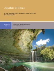
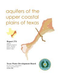
1.0 PLANNING AREA<br />
The planning area for the <strong>Four</strong> Comers water and sanitary sewer study encompasses<br />
approximately 1,775 acres of land located in north central Fort Bend County, <strong>Texas</strong>. The<br />
planning area boundaries are generally defined by State Highway 6 on the east,<br />
McKaskle Road to the south, FM 1464 to the west and the southern boundary of South<br />
Mission Glen MUD to the north. Major roadways within the planning area include<br />
Richmond-Gaines Road which runs north-south through the area and Boss Gaston/Old<br />
Richmond Road which traverses east to west across the north central part of the planning<br />
area connecting State Highway 6 with FM 1464. Both roads are two-lane asphalt<br />
roadways with open ditch drainage. The entire planning area is not located within the<br />
corporate limits of any city, but lies wholly within the extra-territorial jurisdiction of the<br />
City of Houston. A map of the planning area is shown on page 2 of this section.<br />
Much of the service area consists primarily of open pasture/range land with sparse tree<br />
cover. Ground elevations within the area indicate that the overall slope of the area is from<br />
north to south with elevations ranging from 85 feet to 95 feet mean sea level (1928<br />
NGVD). Red Gully flows from north to south through the area and provides primary<br />
outfall drainage. Smaller lateral channels convey flows to Oyster Creek (south of the<br />
area) and to Red Gully itself.<br />
1.1 GOALS OF PLANNING STUDY<br />
The goal of this planning study is to determine the feasibility of providing public water<br />
and sanitary sewer service to the currently inserved <strong>Four</strong> <strong>Corner</strong>s/Petitt Road area of Fort<br />
Bend County. This area is an unincorporated area of the county. This study will look at<br />
the existing and future water and sanitary sewer demands, define necessary infrastructure<br />
improvements for service. This study will also identify the associated projected costs of<br />
the proposed utilities.<br />
<strong>Four</strong> <strong>Corner</strong>s Area <strong>Water</strong> and Wastewater Facilities Planning Study<br />
FINAL REPORT<br />
Revised 2/10/99<br />
Page 1-1
~<br />
____! Bayou<br />
~Keegons<br />
BISSONNET<br />
(PROPOSED)<br />
DORA<br />
N<br />
I<br />
I<br />
I<br />
I<br />
I<br />
I<br />
I<br />
I MILLER<br />
I<br />
I<br />
I<br />
I<br />
I<br />
I<br />
I<br />
I<br />
I<br />
I<br />
w<br />
-'<br />
.<br />
:::;<br />
""<br />
"'<br />
"'?-<br />
(lLETA<br />
E<br />
W. AIRPDR1<br />
voss<br />
I<br />
I<br />
I<br />
I<br />
I<br />
I<br />
I<br />
I<br />
®I<br />
I<br />
I<br />
..______ _______<br />
J.<br />
'<br />
I<br />
I<br />
;.----·--<br />
\<br />
><br />
w<br />
~<br />
iil<br />
r<br />
~<br />
LEGEND<br />
0<br />
FOUR CORNERS WSC<br />
WATER & WASTEWATER PROJECT<br />
SCALE IN FEET<br />
FIGURE 1<br />
4CORNERI.DWG (URBAN.PCP)
To accomplish this objective, this study will:<br />
a) Collect and review data pertaining to population and land use, soil conditions,<br />
construction materials and methods, and governmental approval and permitting<br />
requirements.<br />
b) Identify potential treated water sources and wastewater treatment facilities for the<br />
area.<br />
c) Define water distribution and sanitary sewer collection system to serve the area.<br />
d) Prepare conceptual costs of the recommended project.<br />
1.2 EXISTING DEVELOPMENT<br />
Within the 1,775 acre planning area, existing development is sparse consisting primarily<br />
of clusters of residential housing (small single family homes and manufactured housing),<br />
isolated commercial development, a solid waste landfill facility, tree farm and<br />
undeveloped/agricultural acreage. Residential development within the area is located<br />
primarily along Richmond-Gaines Road. This includes a pocket of housing units located<br />
at the northwest corner of Richmond-Gaines Road and Boss Gaston Road in addition to<br />
the Sweet City Acres and Atanacia Martinez Tract subdivisions located along Richmond<br />
Gaines Road between Boss Gaston and Mckaskle Road. The other concentration of<br />
housing units is located adjacent to Boss Gaston Road to the west of the solid waste<br />
landfill. Undeveloped areas are generally small, non-contiguous tracts divided among<br />
different landowners.<br />
Much of the acreage surrounding the planning area is in various stages of development<br />
consisting primarily of dense single-family residential subdivisions with water and sewer<br />
services provided by municipal utility districts. Adjacent residential subdivisions to the<br />
<strong>Four</strong> <strong>Corner</strong>s area include: <strong>Water</strong>ford, Kingsbridge Place, Mission Glen, Village of Oak<br />
Lakes and Oak Lakes Estates. In addition, commercial developments are located along<br />
State Highway 6 in many of the adjacent municipal utility districts.<br />
<strong>Four</strong> <strong>Corner</strong>s Area <strong>Water</strong> and Wastewater Facilities Planning Study<br />
FINAL REPORT<br />
Revised 2110/99<br />
Page 1-3
1.3 AREA SOIL CONDITIONS<br />
Rust Environment and Infrastructure contracted with HVJ Associates, Inc. to conduct a<br />
geotechnical site reconnaissance survey of the <strong>Four</strong> <strong>Corner</strong>s area located in Fort Bend<br />
County, <strong>Texas</strong>.<br />
These services included a review of previous geotechnical investigations in the area of<br />
the project, and a site reconnaissance survey. The study covers the general vicinity of<br />
each area. The site reconnaissance was performed along the streets in each study area and<br />
selected adjacent streets.<br />
The available information for this project and the on-site reconnaissance conducted in<br />
October 1998 are summarized as follows:<br />
The <strong>Four</strong> <strong>Corner</strong>s area is located in northeast Fort Bend County and is bounded by the<br />
Bissonnet ROW on the north, SH 6 on the east, a line parallel to McKaskle Road on the<br />
south, and FM 1464 on the west. Keegans Bayou is located immediately north of the site<br />
and Red Gully bisects it. The area is mostly undeveloped, however rural homes are<br />
located throughout the area and some modern residential developed is located in the<br />
northeast part. The Sprint Landfill is located near the center. South and west of Red Gully<br />
the project lies in the Quaternary alluvial deposits associated with the Brazos River<br />
floodplain. Sands and silts, along with clayey soils are common in these alluvial deposits.<br />
Northeast of Red Gully the area is underlain by clayey soils associated with the<br />
Beaumont Formation. Higher groundwater may be expected in the southern part of the<br />
area. Two known active faults are near the area. The nearest known fault is the Clodine<br />
Fault which crosses FM 1464 about 1500 feet northwest of area. The Renn Scarp is<br />
located about 2000 feet northeast of the site. Neither of these faults are known to be<br />
within the <strong>Four</strong> <strong>Corner</strong>s area. During our reconnaissance we did not observe any<br />
conclusive evidence of adverse geological conditions apart from occasional broken or<br />
poor pavement and several buildings with structural damage.<br />
<strong>Four</strong> <strong>Corner</strong>s Area <strong>Water</strong> and Wastewater Facilities Planning Study<br />
Page 1-4<br />
FINAL REPORT<br />
Revised 2110/99
A search and review of existing geotechnical reports firm HVJ Associates files, private<br />
records and public records was done to obtain geotechnical information relevant to the<br />
study areas in this project. Our findings are summarized in the following table.<br />
Service Area Generalized Soil Conditions Groundwater<br />
Level Range<br />
<strong>Four</strong> <strong>Corner</strong>s Surface strata consisting of firm to very stiff 8 to 15 feet<br />
clays and generally underlain by very loose to<br />
medium dense sands and silts<br />
Available geotechnical data indicates that soil conditions in and near the study area are<br />
typical of the Beaumont Formation and Quaternary alluvial deposits. Additional<br />
geotechnical data within the project areas are required to confirm soil stratigraphy at the<br />
facility locations and to provide in situ property information for detailed design. Where<br />
no surficial evidence of active faulting was observed during the field reconnaissance, it<br />
does not preclude the presence of active faults.<br />
Note that this summary does not fully relate findings and opinions of HVJ Associates,<br />
Inc. Those findings and opinions are only related through their full report located in the<br />
Appendix.<br />
1.4 POPULATION- EXISTING AND PROJECTED<br />
1990 Census data for this area of Fort Bend County was obtained from the Houston<br />
Galveston Area Council (HGAC) and used to determine existing population estimates<br />
within the planning area. According to the census data, in 1990 approximately 1,150<br />
people resided within the planning area in 350 housing units which is equivalent to 3.3<br />
persons per household. A recent field survey of the planning area indicates that several<br />
older housing units appear to be uninhabited but that new housing units have been<br />
constructed (primarily in the Atanacia Martinez subdivision) since the 1990 census. For<br />
this water and sewer study, the 1998 estimated population for the planning area was held<br />
at 1, 150 persons with approximately 350 existing housing units within the planning area.<br />
<strong>Four</strong> <strong>Corner</strong>s Area <strong>Water</strong> and Wastewater Facilities Planning Study<br />
FINAL REPORT<br />
Revised 2/10/99<br />
Page 1-5
The population of Fort Bend County grew at an average annual rate of just under ten<br />
percent in the 1980's and continued to grow at an average rate of just under six percent<br />
during the 1990's. The HGAC forecasts that the average annual growth rate within the<br />
county will slow to less than three percent through the year 2020. Historically, the <strong>Four</strong><br />
Comers area has not observed population increases that mirrored the rest of Fort Bend<br />
County. With the construction of water and sanitary sewer facilities within the <strong>Four</strong><br />
Comers area, population increases within the area are to be expected. For the purposes of<br />
this planning study, average annual population increases of three percent (consistent with<br />
the rest of Fort Bend County) were used for the <strong>Four</strong> Comers planning area. Based upon<br />
this rate, the population ofthe <strong>Four</strong> Comers area is projected to increase from 1,150 in<br />
1998 to 2,200 in the Year 2020. Table 1.4.1 includes a summary of the population<br />
information.<br />
TABLE 1.4.1<br />
POPULATION PROJECTIONS<br />
Census Tract 703.51 1990 1998<br />
Census Estimated<br />
Housing Units 350 350<br />
Population 1,150 1,150<br />
Occupants per Household 3.3 3.3<br />
2020<br />
Projected<br />
670<br />
2,200<br />
3.3<br />
1.5 EXISTING/PROJECTED WATER AND SEWER DEMANDS<br />
<strong>Water</strong> and sanitary sewer demands were developed using the estimated 1998 population<br />
of the area and the projected growth through the Year 2020. Demands were based upon<br />
design values for water and sewer utilized by the <strong>Texas</strong> Natural Resource Conservation<br />
Commission (TNRCC). These design values are 120 gallons per capita day for average<br />
daily water demand and 100 gallons per capita day for average daily wastewater demand.<br />
Peaking factors for both water and sewer flows were used to estimate peak daily<br />
demands. The water and sewer demands calculated for the planning area are presented in<br />
Table 1.5.1.<br />
<strong>Four</strong> Comers Area <strong>Water</strong> and Wastewater Facilities Planning Study<br />
Page 1-6<br />
FINAL REPORT<br />
Revised 2/10/99
Projected average daily water demand for the service area is estimated to increase from<br />
138,000 gallons per day (gpd) in 1998 to 264,420 gpd in the Year 2020. Similarly,<br />
average daily sewer flows are estimated to increase from 115,000 gpd in 1998 to 220,350<br />
gpd in the Year 2020. For the purposes of this study, the water distribution and<br />
wastewater collection systems were evaluated for the current demands within the area<br />
and the projected demands in the Year 2020. In addition to the average daily demands,<br />
peak hour water demands and design fire flows defined by the State <strong>Board</strong> of Insurance<br />
are utilized in the water system design. Peak wastewater flows are developed for lift<br />
station design. These flows are also presented in Table 1.5.1.<br />
TABLE 1.5.1<br />
WATER AND SEWER DEMAND PROJECTIONS<br />
Existing<br />
1998<br />
Projected<br />
2020<br />
WATER SYSTEM<br />
Average Daily Demand (gallons)t 1 J 138,000 264,420<br />
Peaky Daily Demand (gpm)t 2 J 240 460<br />
Fire Flow (gpm) 500<br />
500<br />
SANITARY SEWER SYSTEM<br />
Average Daily Demand (gallons)l'J 115,000 220,350<br />
Peak Daily Demand (gallons)t 4 J 460,000 881,410<br />
(I) Based upon 120 gallons per capita day<br />
(2) 2.5 x Average Daily Demand<br />
(3) Based upon 100 gallons per capita day<br />
(4) 4 x Average Daily Demand<br />
1.6 ASSESSED VALUES<br />
Property values for acreage within the planning area were obtained from the Fort Bend<br />
County Appraisal District and were separated into general land classifications including:<br />
agricultural/open space, landfill, light industrial/commercial, rights-of-way/easements<br />
<strong>Four</strong> <strong>Corner</strong>s Area <strong>Water</strong> and Wastewater Facilities Planning Study<br />
FINAL REPORT<br />
Revised 2/10/99<br />
Page 1-7
and single family residential. Table 1.6.1 summarizes the 1998 assessed values for<br />
property in the <strong>Four</strong> Comers area.<br />
Land Classification<br />
Agricultural/Open Space<br />
Light Industrial/Commercial<br />
Landfill<br />
Rights-of-Way/Easements<br />
Single Family(< 1 acre)<br />
Single Family (1-2 acres)<br />
Single Family(> 2 acres)<br />
TABLE 1.6.1<br />
1998 ASSESSED VALVES<br />
TOTAL ASSESSED VALUE<br />
Total Assessed Value<br />
$ 1,589,600<br />
3,982,450<br />
694,650<br />
900<br />
9,211,000<br />
2,321,650<br />
4 724 300<br />
$22,524,550<br />
<strong>Four</strong> Comers Area <strong>Water</strong> and Wastewater Facilities Planning Study<br />
Page 1-8<br />
FINAL REPORT<br />
Revised 2/10/99
2.0 AREA ENVIRONMENTAL ASSESSMENT<br />
2.1. EVALUATION OF AREA'S HISTORIC LAND USAGE<br />
2.1.1. INTRODUCTION<br />
Earth Tech, formerly Rust Environment & Infrastructure, Inc. contracted with<br />
BC&AD Archaeology, Inc. (BCAD) to determine the potential presence of<br />
cultural resources in the areas that could be eligible for inclusion in the National<br />
Register or Historic Places or warrant designation as <strong>Texas</strong> State Archaeological<br />
Land marks. This work is been completed for a Fort Bend County for water<br />
wastewater treating systems study in the <strong>Four</strong> <strong>Corner</strong>s area. This area is shown in<br />
Figure I, Section I.<br />
2.1.2. ENVIRONMENTAL BACKGROUND<br />
The Colorado, Brazos, Trinity, Neches and Sabine Rivers originate north of the<br />
<strong>Texas</strong> Coastal Plain. They flow southward through the plain to the Gulf of<br />
Mexico. These rivers are pro-Pleistocene in age. Smaller creeks such as the<br />
Oyster Creek and Jones Creek developed during the Pleistocene and parallel the<br />
major waterways. Fort Bend County is located in the Western Gulf section of the<br />
Coastal Plain,<br />
Fort Bend County's location in the Western Gulf section of the Coastal Plain<br />
places it within a subtropical belt. The modem climate is characterized by high<br />
humidity. The biggest factor controlling the regional climate is the Gulf of<br />
Mexico. Summers are hot arid humid and winters are generally mild (Story,<br />
1990). The mean annual temperature of the area is 20 degrees centigrade with a<br />
mean average of rainfall of 46.1 inches. Prevailing winds are south and southeast,<br />
except during the winter when fronts shift the wind from the north. The modern<br />
climate is generally considered to be similar to the climate that existed 5,000<br />
years ago.<br />
<strong>Four</strong> <strong>Corner</strong>s Area <strong>Water</strong> and Wastewater Facilities Planning Study<br />
FINAL REPORT Page 2-1
The flora and fauna or the project areas when first settled could include open land,<br />
woodland and wetland habitats. The following are excerpt from a book by A A<br />
Parker (1835).<br />
" . .list of the forest trees, shrubs, vines i.e. red, black, white, willow; post<br />
and live oaks; pine, cedar, cottonwood, mulberry, hickory, ash elm<br />
cypress, box-wood, elder, dogwood, walnut, pecan, moscheto-a species of<br />
locust, holly, haws, hackberry, magnolia, chinquspin, wild peacan, suple<br />
jack, cane brake, palmetto, various kinds of grapevines, creepers, rushes,<br />
Spanish-moss, prairie grass and a great variety offlowers ....<br />
... Then there are bear, mexican hog, wild geese, rabbits and a great variety<br />
of ducks ... "<br />
Wild herbaceous plants that were native to this area include bluestem,<br />
indiangrass, croton. beggerwood. pokeweed. partridgepea, ragweed and fescue.<br />
Examples of native hardwood trees would be oak, mulberry, sweetgum, pecan,<br />
hawthorn, dogwood, persimmon, sumac, hichory, black walnut, maple and<br />
greenbrier.. Coniferous plants included red cedar arid coast juniper. Shrubs<br />
included American beauty berry, farkleberry. yaupon and possumhaw. Wetland<br />
plants such as smartweed, wild millet, bulrushes, saltgrass and cattail are native to<br />
the area (U.S. Department of Agriculture, 1976).<br />
This vegetative environment supported wildlife such as bear, rabbit, red fox, deer,<br />
coyotes, racoon, opossum, muskrat, beaver, alligator, armadillo, squirrel, and<br />
skunk. A wide variety of birds were present such as quail, dove, prairie chicken,<br />
song birds, herons and kingfishers. The area was also a winter home for a number<br />
of migratory birds such as geese, ducks, egrets, coots, etc. (U.S. Department of<br />
Agriculture, 1976).<br />
2.2. EVALUATION OF AREA'S POTENTIAL WETLANDS<br />
2.2.1 BACKGROUND INFORMATION<br />
Pursuant to Section 404 of the Clean <strong>Water</strong> Act and the rules and regulations<br />
promulgated thereunder by the United States Environmental Protection Agency<br />
(EPA) and the United States Army Corps ofEngineers (USACE), the discharge of<br />
dredged or fill material into waters of the United States, including wetlands,<br />
requires the issuance of a permit from the USACE (33 CFR Parts 320-330). For<br />
the purposes of administering the Section 404 permit program, the USACE<br />
defines wetlands as follows:<br />
<strong>Four</strong> <strong>Corner</strong>s Area <strong>Water</strong> and Wastewater Facilities Planning Study<br />
Page 2-2<br />
FINAL REPORT
Those areas that are inundated or saturated by surface or groundwater at a<br />
frequency and duration sufficient to support, and that under normal<br />
circumstances do support, a prevalence of vegetation typically adapted for<br />
life in saturated soil conditions. Wetlands generally include swamps,<br />
marshes, bogs, and similar areas. (33 CFR 328.3)<br />
The Corps ofEngineers Wetlands Delineation Manual (Technical Report Y-87-1),<br />
issued by the USACE in 1987, states that wetlands must possess three essential<br />
characteristics. Under normal circumstances, these characteristics include the<br />
presence of:<br />
• hydrophytic (water-loving) vegetation,<br />
• hydric soils, and<br />
• wetland hydrology.<br />
If all three of these criteria are present on a particular property, then a permit or<br />
notification under Nationwide Permit 26 must be submitted to the USACE in<br />
order to fill all or a portion of those areas.<br />
Anyone conducting a regulated activity or discharge activity within the United<br />
States and its territories must adhere to the provisions of the Clean <strong>Water</strong> Act. If<br />
any contemplated activity might impact waters of the United States, including<br />
adjacent or isolated wetlands, the USACE must be contacted for an official<br />
determination of the presence of jurisdictional wetlands. If jurisdictional wetlands<br />
are found to exist, then any activity which would involve filling or dredging these<br />
wetlands would require the issuance of a permit.<br />
2.2.2 RESOURCE REVIEW<br />
This preliminary wetlands investigation consisted of a review of all available<br />
published data for the study area including topographic maps, a National<br />
Wetlands Inventory map (draft), aerial photographs, infrared aerial photographs,<br />
and soil information published in the Soil Survey of Fort Bend County, <strong>Texas</strong>.<br />
<strong>Four</strong> <strong>Corner</strong>s Area <strong>Water</strong> and Wastewater Facilities Planning Study<br />
FINAL REPORT Page 2-3
Based on this preliminary investigation, numerous waters of the United States,<br />
including wetlands, and areas potentially containing waters of the United States,<br />
were identified within the boundaries of the study area. Following this resource<br />
review, ground truthing field activities were initiated for the purpose of further<br />
identifying waters of the United States, including wetlands, located within the<br />
study area.<br />
2.2.3 FIELD INVESTIGATION<br />
In order to determine the potential presence and extent of jurisdictional waters of<br />
the United States, including wetlands, located within the study area, a preliminary<br />
wetlands determination was conducted. The wetlands field investigation of the<br />
study area was conducted over the course of four days; field investigation dates<br />
included October 15, November 9, November 10, and November 19, 1998.<br />
The field investigation aspect of this project involved the systematic evaluation of<br />
all readily accessible undeveloped parcels of property. Several inaccessible<br />
parcels of land were however not physically visited during this investigation.<br />
Additionally, based on the review of the published resources during the initial<br />
phase of this investigation, urban areas (developed residential, commercial, or<br />
industrial properties) were not investigated for potential wetlands. Also, several<br />
areas which could be inferred as upland areas based on the resource review were<br />
not physically visited during this investigation. Though numerous parcels of<br />
undeveloped land were physically evaluated during this study, each parcel was<br />
not investigated as thoroughly as would be the practice during a more extensive<br />
wetlands determination or delineation activity.<br />
2.2.4 WETLANDS INVESTIGATION FINDINGS<br />
This preliminary wetlands investigation (both the resource review and the field<br />
investigation) resulted in the creation of an exhibit which details the waters of the<br />
United States, including wetlands, which were identified within the boundaries of<br />
<strong>Four</strong> Comers Area <strong>Water</strong> and Wastewater Facilities Planning Study<br />
Page 2-4<br />
FINAL REPORT
the study area. A cursory evaluation of the soils, hydrology, and vegetation in<br />
most of the areas visited during the field investigation phase of this project was<br />
conducted based on field conditions or reviewed resources. For the purposes of<br />
this preliminary wetlands investigation, the undeveloped parcels of property<br />
evaluated during this study were categorized as follows:<br />
• Upland areas or primarily upland areas. These areas were identified using<br />
both the resource review and field investigation phases of this project.<br />
• Wetland areas or potential wetland areas. These areas were identified<br />
using both the resource review and field investigation phases of this<br />
project.<br />
• Areas recently cleared which are developing wetland characteristics.<br />
These areas were identified during the field investigation phase of this<br />
project. At least two parcels of undeveloped property were observed to be<br />
recently cleared; these areas were most likely cleared within the past 6 to 9<br />
months. Each of these areas now possess an undulating ground surface<br />
which is conducive for collecting and trapping water. Wetland vegetation<br />
was observed to be growing in many of the depressions created by the<br />
clearing activities. At present, two of the three wetland criteria (e.g.,<br />
hydrology and vegetation) were met in these areas. Without appropriate<br />
intervention, wetlands may establish in these rather flat, poorly drained<br />
areas. Further research would need to be conducted to determine whether<br />
or not wetlands historically existed in these areas.<br />
• Areas not physically visited. These areas include areas which were not<br />
walked during the field investigation aspect of this study and which the<br />
resource review of these areas was not definitive as to whether or not<br />
wetlands existed in these areas. Based on the ground truthing activities<br />
which were conducted within the study area, most of the areas not<br />
physically visited are most likely to contain upland or primarily upland<br />
areas.<br />
Overall, ground truthing was accomplished for the majority of the undeveloped<br />
parcels of property located within the study area. Additionally, Keegans Bayou<br />
and Red Gully are considered jurisdictional waters of the United States. Any<br />
activities impacting these waters, such as outfalls, road crossings, etc., would need<br />
to be evaluated for potential permitting requirements under Section 404 of the<br />
Clean <strong>Water</strong> Act and/or the Rivers and Harbors Act of 1899.<br />
<strong>Four</strong> <strong>Corner</strong>s Area <strong>Water</strong> and Wastewater Facilities Planning Study<br />
FINAL REPORT Page 2-5
2.3.5 SUMMARY<br />
A thorough wetland determination and/or delineation should be conducted on any<br />
parcels of property identified for the purpose of constructing water or wastewater<br />
facilities. Even areas identified as uplands or primarily uplands in this preliminary<br />
wetlands investigation should be evaluated for potential wetland areas once<br />
potential facility locations have been identified.<br />
This preliminary wetlands investigation was performed by Earth Tech m<br />
accordance with generally accepted practices as set forth in the Corps of<br />
Engineers Wetlands Delineation Manual (Technical Report Y-87-1). Earth Tech<br />
observed the same degree of care and skill generally exercised by wetland<br />
professionals under similar circumstances. The conclusions are based on our<br />
professional judgement regarding the significance of the information gathered<br />
during the course of this study. Specifically, Earth Tech does not and cannot<br />
represent that all or any portion of the study area is in fact jurisdictional waters of<br />
the United States, including wetlands, under Section 404 of the Clean <strong>Water</strong> Act<br />
inasmuch as such legal determinations can only be made by authorized staff<br />
members of the U.S. Army Corps ofEngineers.<br />
2.3. DESCRIPTION OF AREA'S POTENTIAL HISTORIC SITES<br />
2.3.1. HISTORICAL BACKGROUND<br />
The wide variety of native floral and faunal resources supported an indigenous<br />
population in Fort Bend County. When Cabeza de Vaca, a survivor of the<br />
Narvaez expedition to colonize southern Florida, was shipwrecked in 1528 on<br />
what has often been identified as Galveston Island (probably Oyster Bay<br />
Peninsula), he was met by the native Americans of the area (Krieger, 1959). This<br />
group of Native Americans was part of the Karankawa group that was probably<br />
made up to at least five tribes (Aten. 1983). There were three other related native<br />
groups on the upper <strong>Texas</strong> coast at that time; the Akokisa who occupied the<br />
<strong>Four</strong> <strong>Corner</strong>s Area <strong>Water</strong> and Wastewater Facilities Planning Study<br />
Page 2-6<br />
FINAL REPORT
Galveston Bay area northward to Conroe and east to approximately Beaumont;<br />
the Atakapa who occupied the area east of Beaumont into western Louisiana; and<br />
the Bidai who occupied the territory north of the Akokisa which included the<br />
Huntsville and Liberty areas (Aten, 1983). From the ethnohistoric records as well<br />
as (lie archaeological information, the groups were hunting and gathering peoples<br />
(Hester, 1980; Aten, 1983; Story, 1990). From ca. 3000 BC to AD 100, no<br />
important technological or social advances have been identified among the Native<br />
American groups. From AD 100 to AD 800, ceramics were being used the bow<br />
and arrow was introduced and there was some recognition of territorial<br />
boundaries indicating social structure. From AD 800 until contact, there was<br />
refinement in ceramic production and increased use of the bow and arrow.<br />
At the time of contact, the sociopolitical structure of the groups would be<br />
classified as tribes (Aten, 1983). During the warm seasons, they were dispersed in<br />
band sized groups. They gathered into villages during the colder seasons with<br />
populations ranging from 400 to 500. Cabeza de Vaca's account of these groups<br />
was that they lived in a state of starvation the year around even though they had<br />
access to all of the marine resources of a coastal environment. Caleza de Vaca<br />
lived in this area for six years and became a trader for the Native Americans,<br />
bartering sea shells and other coastal products for hides and lithic resources from<br />
inland groups (Newcomb, 1961 ). The archaeological record indicates that<br />
ceramics appeared with the Atakapa in 70 BC, with the Akokisa in AD 100, with<br />
the Karonkawa in AD 300 and with the Bidai in AD 500. The origin of this<br />
ceramic technology would appear to be the Lower Mississippi Valley and was<br />
adopted from east to west over time (Aten, 1983).<br />
Some of the project areas in Fort Bend County were part of the original Stephen<br />
F. Austin colony. Their location along the Brazos River was advantageous, as it<br />
was easily navigated which gave ready access to the Gulf of Mexico.<br />
<strong>Four</strong> <strong>Corner</strong>s Area <strong>Water</strong> and Wastewater Facilities Planning Study<br />
FINAL REPORT Page 2-7
2.3.2. METHODOLOGY<br />
BCAD conducted archival research on the project areas prior to field surveys at<br />
the <strong>Texas</strong> Archaeological Research Laboratory (TARL) and the General Land<br />
Office in Austin, <strong>Texas</strong>; at the Fort Bend County Museum; and it the <strong>Texas</strong> Room<br />
of the Houston Public Library. The files of National Register of Historic Places,<br />
National Register of Eligible Sites and the <strong>Texas</strong> State Archaeological Sites were<br />
reviewed. The General Land Office provided information on the original Spanish<br />
land grants and owners of the project areas. Early <strong>Texas</strong> history was reviewed as<br />
well as the biographies of the original owners of the land tracts. Aerial<br />
photographs were studied to determine more recent land use.<br />
BCAD conducted reconnaissance surveys of the project areas on September 22,<br />
1998 to the extent or ready accessibility to the areas. Natural drainage channels<br />
were located because the banks of waterways were frequently preferred for<br />
campsites by prehistoric peoples.<br />
The architecture of those existing buildings that could meet the requirements for<br />
inclusion in the National Register or Historic Places was examined. The structure<br />
must be fifty years old and meet one or more of the following requirements:<br />
1. The structure is associated with events that have made a significant<br />
contribution to the broad patterns of history.<br />
2. The structure is associated with the lives of persons significant in our past.<br />
3. The structure is important to a particular cultural or ethnic group.<br />
4. The structure is the work of a significant architect, master builder, or<br />
craftsman.<br />
5. The structure embodies the distinctive characteristic of a type, period, or<br />
method of construction, possesses high aesthetic value, or represents a<br />
significant and distinguishable entity whose components may lack individual<br />
distinctions.<br />
6. The structure has yielded or may be likely to yield information important to<br />
the understanding of <strong>Texas</strong> culture or history.<br />
<strong>Four</strong> Comers Area <strong>Water</strong> and Wastewater Facilities Planning Study<br />
Page 2-8<br />
FINAL REPORT
2.3.3. RESULTS OF THE FOUR CORNERS SITE SURVEY<br />
Archival Research - The attached map presents the Clodine, <strong>Texas</strong> U.S.<br />
Geological Survey Map with the <strong>Four</strong> Comers project area superimposed.<br />
Research at T ARL indicated no previously recorded archaeological sites on the<br />
project area. However, nine prehistoric sites (41FB201, 41FB202, 41FB203,<br />
41FB210, 41FB214. 41FB215, 4IFB216, 41FB217 and 4IFB22l) have been<br />
recorded around the northern shores of White Lake located approximately a mile<br />
to the south of the project area.<br />
The original owners of the land in the project area include Jesse H. Cartwright,<br />
Mills M. Battle, D. A Conner, John Leverton, Andrew M. Clopper and the I. &<br />
G.N. RR Co. Jesse H Cartwright has been discussed in the history of the<br />
Cummings Road project area. Mills M. Battle was also a member of the "Old<br />
Three Hundred" of the Austin colony. He is listed as a contractor and carpenter in<br />
business. He was at various times, justice of the peace, deputy clerk of the probate<br />
court, notary public and county clerk in Fort Bend County. He helped nominate<br />
Sam Houston for President of the Republic of <strong>Texas</strong> in 1841 (Tyler, 1996). No<br />
background information could be located for D. A. Connor and John Leverton.<br />
Andrew M. Clopper was the son of Nicholas Clopper. Nicholas Clopper joined<br />
the Austin colony in 1822 and was instrumental in developing a trade route using<br />
Buffalo Bayou. Nicholas was responsible for the acquisition of the "Twin Sisters"<br />
used in the Battle of San Jacinto (Tyler, 1996). Andrew was a courier for<br />
President David Burnett during the <strong>Texas</strong> Revolution and later worked as a<br />
surveyor in the general area (Lapham Letters, 1909). Also shown on Figure VI is<br />
the estimated route of General Santa Anna on April I 4th and 15th of 1836 on his<br />
way to Harrisburg and eventually, the Battle of San Jacinto (Wharton, 193 9). This<br />
route was reconstructed using the personal narrative of Jose Enrique de Ia Pena as<br />
well as recollections handed down from eyewitness accounts. Santa Ana crossed<br />
the Brazos River on April 14th, 1836 at Thompsons Ferry, moved north crossing<br />
Jones Creek and supposedly made camp at nightfall on the western Andrew<br />
<strong>Four</strong> <strong>Corner</strong>s Area <strong>Water</strong> and Wastewater Facilities Planning Study<br />
FINAL REPORT Page 2-9
cay whatley<br />
'\.<br />
'\.<br />
---~--<br />
'\.<br />
'\.<br />
-----;:-;-'
Clopper land tract. By noon on April 15, 183 6, he had moved southeast and burnt<br />
the plantation of William Stafford (located just cast of the George Brown and<br />
Charles Belknap tract) which has been documented historically. This route on the<br />
morning or April 15th could have taken him across the southern portion of the<br />
<strong>Four</strong> <strong>Corner</strong>s project area. The actual route has not been firmly documented<br />
historically or archaeologically (Jeff Dunn, personal communication, 1998).<br />
There is no archival evidence that any of the original owners of the land built<br />
plantations or habitations in the project area. In the case of Battle and Cartwright,<br />
it is more likely that their residences would have been built on Oyster Creek,<br />
south of the project area. Since first settled, the main land use of the project area<br />
has been for growing crops (corn, cotton potatoes and sugar cane) and/or for<br />
grazing cattle and horses (Lipham Letters, 1909). A 1956 aerial photograph,<br />
shows that the entire project area has been under cultivation at some time (Fort<br />
Bend Soil Survey, 1956). Approximately, thirty houses exist on this photograph<br />
that are also present in the attached map.<br />
The highest potential for prehistoric sites in this area is along the banks of<br />
Keegans Bayou located behind the Kingbridge <strong>Development</strong> in the upper<br />
northeast section of the area and the banks of two drainage channels, one in the<br />
northwestern section of the project area drains into Red Gully in the southwest<br />
section of the project area. Keegans Bayou appears to have been rerouted to its<br />
present location and the area has been extensively modified by new construction.<br />
Limited access to the banks of the drainage channels prevented a complete walkthrough<br />
survey of these areas for potential prehistoric sites. However, limited<br />
observations during the field survey and the aerial photographs indicate that the<br />
northwest drainage channel has been heavily impacted by cultivation as well as<br />
construction since 1956. Visual observations indicate that the banks of Red Gulch<br />
have been extensively modified from the southwestern point adjacent to the<br />
landfill to the southern edge of the project area by landfill operations and<br />
<strong>Four</strong> <strong>Corner</strong>s Area <strong>Water</strong> and Wastewater Facilities Planning Study<br />
FINAL REPORT Page 2-11
construction. Visual observations and the aerial photographs indicate that the<br />
banks of the western extension of Red Gulch to the western boundary of the<br />
project area have been impacted by cultivation.<br />
The remaining houses that meet the age requirement for the National Register of<br />
Historic Places were examined and only one could possibly qualify based on any<br />
of the other requirements. This is the residence at 9427 Gaines Road. There was<br />
no evidence of any remains of preexisting historic structures on the rest of the<br />
project area which has also been heavily impacted by cultivation and new<br />
construction based on limited visual observations and the aerial photographs.<br />
2.3.4. FOUR CORNERS SITE SPECIFICS<br />
The residence at 9427 Gaines Road could possibly qualify for the National<br />
Register ofHistoric Places. Avoidance of this structure is recommended.<br />
The archival research has indicated that there is a probability that the southern<br />
portion of the <strong>Four</strong> Comers area was crossed by Santa Anna's army during the<br />
<strong>Texas</strong> Revolution. There is however, little probability of finding significant<br />
archaeological deposits associated with this event because the army marched<br />
rather quickly between the previous night's campsite and Stafford's plantation. It<br />
might be possible to find isolated artifacts, but nothing that would add to the<br />
better understanding of <strong>Texas</strong> History. It is unlikely that any further<br />
archaeological studies would be required concerning this event. However, if<br />
during construction of the proposed projects artifacts relating to this event are<br />
found, an archaeologist should be contacted.<br />
2.4. EVALUATION OF AREA'S POTENTIAL ENDANGERED<br />
SPECIES HABITATS<br />
<strong>Four</strong> <strong>Corner</strong>s Area <strong>Water</strong> and Wastewater Facilities Planning Study<br />
Page 2-12<br />
FINAL REPORT
As part of the environmental investigation of the study area, the <strong>Texas</strong> Parks and<br />
Wildlife Department and the U.S. Fish and Wildlife Service were contacted<br />
regarding the possible occurrence of threatened or endangered species within the<br />
boundaries of the study area.<br />
In correspondence dated September 30, 1998, the <strong>Texas</strong> Parks and Wildlife<br />
Department (TPWD), <strong>Texas</strong> Biological Conservation Data System office, the<br />
TPWD Wildlife Habitat Assessment Program, and the U.S. Fish and Wildlife<br />
Service (USFWS) were officially contacted for a review of sensitive species (e.g.,<br />
threatened or endangered species) and natural communities which could<br />
potentially occur within the study area.<br />
In correspondence dated October 6, 1998, the USFWS stated that a review of the<br />
U.S. Fish and Wildlife Service files and your project information indicate that no<br />
federally listed or proposed threatened or endangered species are likely to occur at<br />
the project site."<br />
In correspondence dated October 14, 1998, the TPWD Wildlife Habitat<br />
Assessment Program stated that sensitive wildlife habitats that should incorporate<br />
planning considerations within this study area include mature woodlands, riparian<br />
vegetation associated with creek drainage, native grasslands, and wetlands.<br />
<strong>Development</strong> of project alternative alignments should include considerations for<br />
sequentially avoiding, minimizing or compensating losses of these sensitive<br />
habitats. Where possible, water and wastewater lines should follow existing<br />
rights-of-way. Mitigation measures to offset unavoidable losses to these habitats<br />
should be included in project planning. Such measures may include provisions for<br />
tree and shrub plantings and for revegetation of disturbed areas using native plant<br />
species." Such ecological considerations would need to be taken into account<br />
once project alternatives or options have been identified.<br />
<strong>Four</strong> <strong>Corner</strong>s Area <strong>Water</strong> and Wastewater Facilities Planning Study<br />
FINAL REPORT Page 2-13
As of November 24, 1998, correspondence from the TPWD <strong>Texas</strong> Biological<br />
Conservation Data System office has not been received. To date, information<br />
received by the USFWS and TPWD indicate that threatened and endangered<br />
species of plants and animals are not considered to be a concern within the<br />
confines of the study area.<br />
All correspondence pertaining to threatened and endangered species is provided in<br />
Appendix D of this report.<br />
2.5. EXTENT OF FLOOD PLAIN IN AREA<br />
As part of this investigation, the Federal Emergency Management Agency<br />
(FEMA) National Flood Insurance Program Flood Insurance Rate Maps (FIRMs)<br />
were evaluated for the study area. The FIRM panel 120 of 550, map number<br />
48157C0120-H, dated September 30, 1992, and map number 48157C0120-J,<br />
dated January 3, 1997, were reviewed for this project.<br />
The northeastern-most corner of the study area boundary crosses the well defined<br />
channel of Keegans Bayou at two locations. Keegans Bayou is designated as a<br />
"Zone AE" area which consists of a special flood hazard area potentially<br />
inundated by a 100-year flood. The 100-year flood is contained within the channel<br />
of Keegans Bayou in this area according to the FIRMs reviewed during this<br />
investigation. Zone AE specifically refers to areas of the 100-year flood in which<br />
base flood elevations have been determined.<br />
The southwestern-most corner of the study area is encompassed by a flood zone<br />
associated with Red Gully, based on the FIRMs reviewed for this area. Red Gully<br />
generally flows southeast and south within the boundaries of the study area and<br />
then flows south/southeast into Oyster Creek. Oyster Creek flows into the Brazos<br />
River which then flows into the Gulf of Mexico.<br />
<strong>Four</strong> <strong>Corner</strong>s Area <strong>Water</strong> and Wastewater Facilities Planning Study<br />
Page 2-14<br />
FINAL REPORT
The area surrounding Red Gully is designated as a Zone AE. This area which<br />
consists of a special flood hazard area that has a potential to be inundated by a<br />
I 00-year flood; floodway areas in Zone AE are also designated on the FIRMs.<br />
The Red Gully I 00-year flood zone is not contained within the channel similar to<br />
the well defined channel ofKeegans Bayou.<br />
Additionally, a Zone X area is also located in the southwestern-most corner of the<br />
study area. Zone X areas are defined as areas below the 500-year flood elevation<br />
and areas within the I 00-year flood area with average depths of less than one foot<br />
or with drainage areas less than one square mile, and/or areas protected by levees<br />
from the 100-year flood. Specifically, Sweet City Acres, a small residential<br />
subdivision located along the southern boundary of the study area, consists of an<br />
area protected from the 100-year flood by a levee; this levee could however be<br />
subject to possible failure or overtopping during larger floods.<br />
Aside from the channel of Keegans Bayou, located in the northeastern corner of<br />
the study area, and the area surrounding Red Gully, located in the southwestern<br />
corner of the study area, no other flood zones were identified during the course of<br />
this study.<br />
Figure II illustrates the FEMA designated flood zones located within the study<br />
area.<br />
<strong>Four</strong> <strong>Corner</strong>s Area <strong>Water</strong> and Wastewater Facilities Planning Study<br />
FINAL REPORT Page 2-I5
lll'v122<br />
-<br />
LECENU<br />
Sl'lllAl I lOUD HAl.ARil AIUAS INUNlJATW<br />
BY 100-YfAR fLOOD<br />
ZONf A<br />
ZONE AE<br />
ZONE Ali<br />
No t,,.,. 6'""' u•!ly •••••<br />
uf pood,ng1 b.-e n,~>d ~~·•t•onl<br />
dt·lt'<br />
drltom"'~ r ... ••••• .... nu ...ol r ... floodmJ<br />
""""''''"' olo.o drlri~d<br />
ZONE A¥9<br />
lo Lt l"'~•<br />
z<br />
"' 0<br />
~f:::lu<br />
co::~ o<br />
~~ r5<br />
z_, "'<br />
Qct_ I-<br />
- a:<br />
~ 0<br />
z "<br />
::;<br />
::;<br />
-lJD<br />
D<br />
ZONE V<br />
ZONE VE<br />
(o.. oly houod '"'''<br />
ollu ol 1.-.1 11wr><br />
1 1<br />
undttoomo""d<br />
~E X<br />
FORT BEND COUNTY<br />
UNINCORPORATED AREAS<br />
480ZZ8<br />
FLOOD HAZARDS SHOWN WITHIN<br />
THE CITY OF HOUSTON ARE FOR INF!IJTION<br />
ONLY. FOR FLOOD INSURANCE PURPOS REFER<br />
SEPARATELY PUBLISHED FLOOD INSUR CE<br />
~<br />
UNOtVHOPW COASTAl BARRIERS<br />
D<br />
D<br />
klo~ ldtnlllood Qlho""i'"<br />
19U 1,.0 f'
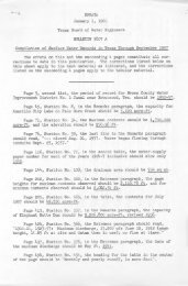
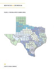
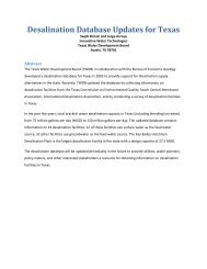
3.0 EVALUATION OF AREA EXISTING PRIVATE WELLS AND<br />
EXISTING SEPTIC SYSTEMS<br />
The <strong>Four</strong> <strong>Corner</strong>s area considered by this study generally consists of low income<br />
residential housing including small single family houses and mobile homes. Some<br />
light commercial developments are interspersed within residential development in<br />
the area. Currently, no community water system exists in the <strong>Four</strong> <strong>Corner</strong>s area.<br />
Private water wells supply the limited domestic water to residences in the area.<br />
Sanitary sewage treatment is accomplished by with septic fields serving individual<br />
lots. The approximate locations of existing private water wells and existing private<br />
septic systems are shown on the attached Exhibit A<br />
Monitoring wells around the Sprint Landfill located in the center of the study area.<br />
Samples from monitoring wells were analyzed for the following:<br />
Cadmium (dissolved)<br />
Chloride<br />
Iron (dissolved)<br />
Manganese (dissolved)<br />
Total Dissolved Solids<br />
Zinc (dissolved)<br />
SP Conductance<br />
pH<br />
Total Organic Carbon<br />
Lead (dissolved)<br />
Of those listed the regulated inorganic chemicals listed in the Safe Drinking <strong>Water</strong><br />
Act regulations are, Cadmium and Lead. The maximum contaminant limit for these<br />
is 0.005 mg/1 and 0.015 mg/1 respectively. The SDWA lead and copper rule<br />
determining values for drinking water are to be established from customer tap<br />
samples and take into account background concentration levels. It is not known<br />
what background levels may be present to enable a determination whether levels<br />
indicated in monitoring reports are elevated above normal levels.<br />
<strong>Four</strong> <strong>Corner</strong>s Area <strong>Water</strong> and Wastewater Facilities Planning Study<br />
FINAL REPORT<br />
Revised 2/10/99<br />
Page 3-1
Test results received from the TNRCC for monitoring wells are located m<br />
Appendix G.<br />
Based upon information from the Fort Bend appraisal district maps and records, the<br />
typical residential lot size (east of Richmond_ Gaines Road) is 70' x 150'. This<br />
typical lot size is inadequate to meet the TNRCC's distance requirements between<br />
an on-site treatment facility and a public drinking water well. A close distance<br />
between waste and water facilities contributes to drinking water quality<br />
deterioration.<br />
<strong>Four</strong> <strong>Corner</strong>s Area <strong>Water</strong> and Wastewater Facilities Planning Study<br />
Page 3-2<br />
FINAL REPORT<br />
Revised 2110/99
~<br />
~<br />
~<br />
DISSONNET<br />
~<br />
~ ~<br />
~ ~<br />
I:J()SS--(;ASTON ROAD<br />
~~----~ ...<br />
_------------<br />
!<br />
~<br />
~<br />
---<br />
HISSONNET<br />
HL&P mr E.SMT<br />
STREIT<br />
Pl:lfTT<br />
ENNIS<br />
ZINDLER<br />
I<br />
5<br />
8<br />
ii1<br />
BISSONNET<br />
OiJ) RIClfMOfo'lD<br />
STREET<br />
~-<br />
_ u\':.sat>~t>~Er s1.~------ -----<br />
- -~------<br />
I!~··<br />
0"-<br />
•<br />
I<br />
~1~<br />
~<br />
~<br />
~<br />
j<br />
.,.<br />
I<br />
&>55-GASTON ROAD<br />
HOSS-GASTON ROAD<br />
~<br />
~<br />
IRENE<br />
\LI'll< :,;·,Jt.'.; I'W\'\ll<br />
W\1111 'J.JII 11
4.0 PROJECT JUSTIFICATION<br />
4.1. EXISTING CONDITIONS<br />
The Fort Bend County, <strong>Four</strong> <strong>Corner</strong>s area is an unincorporated area within the county<br />
that is home to approximately I, 150 primarily low income, minority residents. There<br />
currently is no public water supply or wastewater collection and treatment. Currently,<br />
residents obtain water from private wells. To date, some of the area's homeowners<br />
shallow water wells have gone dry, forcing them to get water from their neighbor's<br />
wells. Some residents use privies and other inadequate means of on-site sewage<br />
disposal. On-site sewage disposal systems located on small lots can contribute to<br />
groundwater well contamination. Contaminated well water by the inadequate disposal<br />
methods poses a health hazard to area residents. It has been estimated that 90% of the<br />
area residents buy bottled water. Additional residents moving into the <strong>Four</strong> <strong>Corner</strong>s<br />
area has stress the already inadequate resources.<br />
4.2. DISCUSSION OF HISTORY OF HEALTH VIOLATIONS<br />
According to Fort Bend County Environmental Health Department there have been<br />
approximately one hundred seventy (170) complaints for septic systems in the project<br />
area over the past ten (10) years. The locations of the complaints by street name are<br />
listed in Table 4.1.<br />
Table 4.1<br />
STREET NUMBER OF COMPLAINTS<br />
Adelfina 19<br />
Aurora 8<br />
Blake 1<br />
Frank 16<br />
Martinez 18<br />
Old Richmond Road 13<br />
Paul 34<br />
Sam 24<br />
Second 17<br />
Severo 8<br />
Tomasa 12<br />
Total 170<br />
<strong>Four</strong> <strong>Corner</strong>s Area <strong>Water</strong> and Wastewater Facilities Planning Study<br />
FINAL REPORT<br />
Revised 2/22/99<br />
Page 4-1
Currently operating on-site treatment systems are experiencing a high degree of failure to<br />
properly treat the area population's domestic waste. This condition can primarily be<br />
attributed to the overloading of the existing systems. Higher household populations than<br />
systems can handle and inadequate treatment system maintenance. The high number of<br />
complaints is evidence of the pressing need of the area to have wastewater collection<br />
system in place to replace the stressed on-site treatment systems currently in use in the<br />
area.<br />
<strong>Four</strong> <strong>Corner</strong>s Area <strong>Water</strong> and Wastewater Facilities Planning Study<br />
Page 4-2<br />
FINAL REPORT<br />
Revised 2/10/99
t<br />
'"""'""'"<br />
--------=---=<br />
...;<br />
'<br />
'.<br />
-<br />
-~<br />
I II II II C1S'roN<br />
~<br />
!<br />
'<br />
~<br />
BOSS .<br />
I I I<br />
//<br />
I<br />
bud<br />
l llUTA<br />
P£Trr ,,.,., RY I<br />
EHHI$<br />
FOUR CORNERS;!'EllTT<br />
ROAD AREA<br />
FORT BEND COUNTY<br />
J t--<br />
J;--1 w~<br />
I<br />
_...l---<br />
li'<br />
IR£H.f_<br />
j<br />
i<br />
AURORA<br />
g I<br />
FR-<br />
~<br />
§<br />
•• ~<br />
I AUCN<br />
S(I[RQ<br />
IIN!llNEZ I<br />
~,. ..<br />
I<br />
NlfiFINA<br />
HUSOIAA<br />
• _1_ ....<br />
I<br />
I<br />
I.IOIASKU:<br />
lOMASA<br />
j<br />
,p<br />
f.<br />
"'<br />
LEGEND<br />
SEPTIC SYSTEM -<br />
+ WATER WELL<br />
NOTE:<br />
PRIVATE<br />
THE ONLY SEPTIC SYSTEMS APPEARING<br />
ON THIS EXHIBIT ARE THOSE THAT<br />
HAVE BEEN INSPECTED BY THE FORT<br />
BEND COUNTY HEALTH DEPARTMENT<br />
~CHARLES<br />
D. GOODEN<br />
CONSULTING<br />
BNGINEERB,INC.<br />
26$6 SOI1IH LOOP WBST, IIUI'11I 310<br />
H
5.0 ALTERNATIVE WATER AND WASTEWATER SYSTEMS<br />
5.1 CHEMICAL ANAL VIS-ADJACENT PUBLIC WATER WELLS<br />
Engineering consultants and water/sewer operators for Municipal Utility Districts in the<br />
area adjacent to the <strong>Four</strong> <strong>Corner</strong>s planning area were contacted regarding available<br />
chemical analyses of existing water supply wells. Information was provided for public<br />
water supply wells in Fort Bend County MUD No. 2, Kingsbridge MUD, North Mission<br />
Glen MUD and Fort Bend County MUD No. 41.<br />
Based upon the information provided by the water system operators, water supply wells<br />
within each of the four adjacent districts are within the regulatory maximum contaminant<br />
levels for minerals, metals and volatile organic compounds. These maximum contaminant<br />
levels are established by the <strong>Texas</strong> Natural Resource Conservation Commission. Total<br />
hardness for water from several of the wells is classified as moderate to hard. However,<br />
this is not uncommon for groundwater supplies in the Gulf Coast area and does not pose<br />
problems for use as potable water supply.<br />
5.2 AREA HYDROGEOLOGIC CONDITIONS AND - GENERAL<br />
SOIL GROUNDWATER CHARACTERISTICS<br />
The soils encountered in the reports reviewed are typical of the Beaumont formation and<br />
the Quaternary alluvial deposits. Based on the geotechnical information from these<br />
reports, we do not expect any unusual problems in the project areas. Most of the soils<br />
may be tentatively classified as type B for stiff to hard clays above the water table, and<br />
type C for weaker clays, granular soils and soils below the water table, based on OSHA<br />
trench safety requirements as presented in Appendix B of 29 CFR part 1926. Since some<br />
of the borings were drilled at distances up to about 5 miles from the project areas, we are<br />
uncertain of soil conditions at specific project locations.<br />
Groundwater level measurements were documented in several of the projects reviewed. It<br />
should be noted, however, that groundwater levels may fluctuate seasonally, climatically<br />
<strong>Four</strong> <strong>Corner</strong>s Area <strong>Water</strong> and Wastewater Facilities Planning Study<br />
FINAL REPORT<br />
Revised 2/10/99<br />
Page 5-l
and due to other factors not evident at the time of drilling. If clay soils exist to a<br />
significant depth below the base of the trench excavation, a pump and sump dewatering<br />
system will probably be adequate for trench excavation. If granular soils are encountered<br />
above or close to the base of excavation, a well point dewatering system may be required.<br />
Thirteen investigations containing 72 borings were reviewed for this sub-area. The<br />
terminal depths of the borings ranged from 5 to 50 feet below ground surface. The soils<br />
encountered were mostly firm to very stiff clay, sandy clay, and silty clay surface<br />
stratums which ranged in thickness from 4 to 25 feet. The plasticity index of the cohesive<br />
soils ranged from about 10 to 70. The cohesive soils were generally underlain by very<br />
loose to medium dense sands and silts. Most of the very sandy and silty soils with<br />
plasticity indices less than 7 occurred to the south of the sub-area where surface strata<br />
occasionally consisted of sands and silts. Calcareous and ferrous nodules were usually<br />
scattered throughout the depth of exploration for most of the borings in and near the subarea.<br />
Surface layers of fill material ranging from about 2 to 4 feet in thickness occurred<br />
fairly often on the boring logs. In one case, the fill material extended to about 10 feet<br />
below ground surface. Groundwater was recorded at levels ranging from 8 to 15 feet<br />
below ground surface. However, several borings with depths up to 20 feet were dry.<br />
5.3 WATER AND WASTEWATER SYSTEM REQUIREMENTS<br />
Public water distribution and supply systems must be designed in accordance with <strong>Texas</strong><br />
Natural Resource Conservation Commission (TNRCC) permanent rules, Chapter 290<br />
(<strong>Water</strong> Hygiene). Sanitary sewer collection and treatment systems must be designed in<br />
accordance with TNRCC permanent rules, Chapter 317 (Design Criteria for Sewage<br />
Systems). The <strong>Four</strong> Comers planning area lies within the Extra-Territorial Jurisdiction of<br />
the City of Houston. In addition to the requirements of TNRCC, water and sanitary<br />
sewer facilities must be designed in accordance with the September 1996 "Design<br />
Manual for Wastewater Collection Systems, <strong>Water</strong> Lines, Storm Drainage and Street<br />
Paving" issued by the City of Houston Department of Public Works and Engineering.<br />
City of Houston design requirements are more stringent than TNRCC with respect to<br />
<strong>Four</strong> Comers Area <strong>Water</strong> and Wastewater Facilities Planning Study<br />
Page 5-2<br />
FINAL REPORT<br />
Revised 2/l 0/99
certain design elements of water and wastewater systems. Construction drawings for<br />
water and sanitary sewer facilities must be approved and signed by the City of Houston<br />
prior to the initiation of construction.<br />
WASTEWATER COLLECTION SYSTEM<br />
The gravity sanitary sewer system design is based on minimum lateral pipe diameter of 8<br />
inches. The service leads may be as small as 6 inches. Minimum grades for various pipe<br />
diameters in the design are listed the following table.<br />
Diameter (in.)<br />
6<br />
8<br />
10<br />
12<br />
Grade(%)<br />
0.65<br />
0.44<br />
0.33<br />
0.26<br />
The grades above will provide a minimum full-flow velocity of 2.3 feet per second to<br />
minimize sedimentation in the pipe. All gravity line design calculations are based on a<br />
Manning's "n" value of 0. 013.<br />
All wastewater collection lines were designed with capacity to meet flow requirements<br />
described in other sections of this report. Flow capacities based on the above minimum<br />
grades for each pipe size are listed in the following table.<br />
Diameter (in.)<br />
6<br />
8<br />
10<br />
12<br />
Capacity (gpd)<br />
303,400<br />
518,030<br />
813,420<br />
1,174,070<br />
Minimum depth at the upstream end of all lateral sewers is 3 feet from natural ground to<br />
top of pipe. This is necessary to allow for connections from individual housing units.<br />
Maximum depth of 8 inch, 10 inch and 12 inch pipe is 20 feet from natural ground to<br />
pipe flowline per City of Houston guidelines. This limitation reduces the construction of<br />
deep sanitary sewers in areas with potential for water bearing sands. To take advantage of<br />
the lesser grades, several pipes were over-sized, with excess flow capacity. This allowed<br />
<strong>Four</strong> Comers Area <strong>Water</strong> and Wastewater Facilities Planning Study<br />
FINAL REPORT<br />
Revised 2110/99<br />
Page 5-3
for greater distances between lift stations while minimizing the number of lift stations<br />
and the depth of gravity sewers.<br />
Wet well dimensions will vary with each lift/pump station and with the phase of<br />
construction being considered. The diameter of the wet well must accommodate the<br />
number of pumps needed to handle the design flow while maintaining adequate clearance<br />
between each pump. Wet well volume is a function of flow rate and pump cycle time.<br />
Minimum allowable cycle time is 6 minutes from start to start. The size of pumps<br />
required varies from ~2 hp to ~45 hp.<br />
Due to the distance between the service area and the source of wastewater treatment, a<br />
pump station and force main will be needed to serve Area I. The flows for the pump/ lift<br />
station for Area I vary substantially from initial to ultimate conditions. This station<br />
should be designed with two pumps for the initial conditions and will ultimately require<br />
three pumps to meet future conditions. The wet well should be large enough to allow for<br />
a third pump to be added as future demands warrant it. At that time, two pumps will<br />
handle the design flow, and the third will operate as a backup.<br />
The lift stations, which are significantly smaller than the pump station, reqmre<br />
installation of only two pumps for operation. Lift station pumps should be selected such<br />
that a single pump can handle the design flow allowing the second pump to serve as<br />
backup. The lift stations for Area 2 and 3 should be designed to transition from initial to<br />
ultimate flows, if necessary, by pump modifications.<br />
WATER DISTRIBUTION SYSTEM<br />
In addition to hydraulic and pressure considerations, the following design criteria was<br />
applied to sizing the water distribution system.<br />
Diameter<br />
4-inch<br />
Design Limitations<br />
Only on dead-end lines within cui-de-sacs supplying maxrmum of I6<br />
connections.<br />
<strong>Four</strong> <strong>Corner</strong>s Area <strong>Water</strong> and Wastewater Facilities Planning Study<br />
Page 5-4<br />
FINAL REPORT<br />
Revised 2/10/99
6-inch<br />
8-inch<br />
Maximum length is I 000 feet when interconnected between two waterlines<br />
8-inch or larger.<br />
Maximum length is 500 feet on permanent dead-end terminating with fire<br />
hydrant or flushing valve.<br />
Only one fire hydrant or flushing valve is allowed.<br />
Required for line lengths greater than 1000 feet or when two or more fire<br />
hydrants/flushing valves required.<br />
~ 12-inch To be determined by the Professional Engineer and verified by City of<br />
Houston <strong>Water</strong> Engineering Section.<br />
<strong>Water</strong> line diameter selection is also impacted by pressure requirements in the system.<br />
Minimum working pressure under normal conditions should exceed 35 pounds per square<br />
inch (psi) at all points in the system. When the system is expected to provide fire-fighting<br />
capability, a minimum pressure of 20 psi must be maintained under combined fire and<br />
drinking water flow conditions.<br />
Gate valves on waterlines 4 inch through 12 inch in diameter must be spaced at a<br />
maximum of 1000 feet. Valves must also be placed at line intersections. The number of<br />
valves should equal the number lines leading out of the intersection minus one. Fire<br />
hydrants in a single family residential development should be spaced at 500 feet.<br />
5.4 ALTERNATIVE SYSTEM LAYOUTS<br />
Two concepts for water supply and wastewater treatment were investigated as part of this<br />
study. One concept included the construction of a water supply plant and wastewater<br />
treatment plant within the limits of the planning area (referred to as the "On-site" option)<br />
which would provide services only for properties within the planning area boundaries.<br />
The other concept involves the acquisition of "surplus" capacity in water supply and<br />
wastewater treatment facilities within neighboring municipal utility districts. Use of<br />
surplus capacity requires the <strong>Four</strong> Comers area to construct only the water distribution<br />
and wastewater collection systems within their area and these systems would then be<br />
"hooked up" to the adjacent water supply and wastewater treatment plants. Only two<br />
adjacent districts, Kingsbridge MUD and North Mission Glen MUD indicated that water<br />
<strong>Four</strong> Comers Area <strong>Water</strong> and Wastewater Facilities Planning Study<br />
FINAL REPORT<br />
Revised 2/10/99<br />
Page 5-5
and/or sewer capacity was currently available or would be available in the near term (see<br />
Section 10 for summary of all district contacts).<br />
Appendices A, B, and C provide water distribution and wastewater collection system<br />
layouts for the alternatives considered from Kingsbridge MUD, North Mission Glen<br />
MUD, and On-site, respectively. <strong>Water</strong> distribution layouts are shown only for the Onsite<br />
option and connection to Kingsbridge MUD. North Mission Glen is currently<br />
evaluating their water supply system and will not be able to assess their surplus water<br />
capacity until completion of their study. Wastewater collection systems are shown for all<br />
three options.<br />
The wastewater collection schemes for the On-site, Kings bridge MUD and North Mission<br />
Glen MUD options are very similar with 12-inch gravity trunk sewer lines being located<br />
on Richmond-Gaines Road and Boss-Gaston Road and 8-inch gravity sewer lines being<br />
used throughout the residential areas. Three lift/pump stations are required to provide<br />
service to the total planning area because of the size of the planning area, the limitations<br />
on the depths of gravity sanitary sewer construction and the potential for construction in<br />
wet sand conditions. Under the On-site scenario, one of the three stations would be<br />
constructed at the site of the wastewater treatment plant facility.<br />
Under the Kingsbridge MUD and North Mission Glen MUD scenarios, the wastewater<br />
from the <strong>Four</strong> Comers area will be collected into a single pump station to be located<br />
adjacent to Old Richmond Road south of Boss-Gaston Road. From this pump station,<br />
wastewater will be pumped via force main to an existing 12-inch gravity sanitary sewer<br />
located at the intersection of Bissonnet Road and Richmond-Gaines Road (Kingsbridge<br />
MUD scenario) or to the North Mission Glen MUD wastewater treatment plant located<br />
on Keegans Bayou, north of the <strong>Four</strong> <strong>Corner</strong>s area (North Mission Glen scenario).<br />
For the On-site scenario, a wastewater treatment plant site is tentatively located along Old<br />
Richmond Road near the southern limits of the planning area and discharges to Red<br />
Gully. No specific tract of land has been identified at this time for the treatment plant site.<br />
<strong>Four</strong> <strong>Corner</strong>s Area <strong>Water</strong> and Wastewater Facilities Planning Study<br />
Page 5-6<br />
FINAL REPORT<br />
Revised 2/l 0/99
However, the southern portion of the planning area provides the most accessible<br />
possibilities for outfall into Red Gully.<br />
<strong>Water</strong> distribution system layouts for the on-site and Kingsbridge scenanos are very<br />
similar with the use of 12-inch water mains along Richmond-Gaines and Boss-Gaston<br />
Roads. Six-inch and eight-inch water lines are used throughout the rest of the system.<br />
Under the Kingsbridge scenario, the <strong>Four</strong> Comers distribution system will connect to the<br />
Kingsbridge water supply through an existing 12-inch water line located on Boss-Gaston<br />
Road east of Richmond-Gaines Road and to an existing 12-water line located at the<br />
intersection of Bissonnet and Richmond-Gaines. This layout will provide the <strong>Four</strong><br />
Comers area with two points of connection to the Kings bridge water supply system.<br />
The on-site water scenario shows the construction of a water supply plant near Old<br />
Richmond Road south of Boss-Gaston Road. As with the on-site wastewater system<br />
scenario, no specific tract of land has been identified for the water plant location.<br />
However, the location shown on the layout in Appendix C is centrally located to the<br />
entire planning area.<br />
5.5 ALTERNATIVE SYSTEMS COSTS<br />
Construction cost estimates for the alternative water and sewer systems evaluated in the<br />
study were broken down into two separate components. The first component included<br />
the construction costs for water distribution and wastewater collection systems within the<br />
<strong>Four</strong> Comers planning area. The configurations of these systems were dictated by the<br />
physical locations of water supply and wastewater treatment in addition to regulatory<br />
requirements. The second component involves the construction costs for the water supply<br />
plant and the wastewater treatment plant which are based upon the cost of new facility<br />
construction or in the case of existing plant availability, the capital recovery costs of the<br />
facilities already constructed. All construction cost estimates are based upon current unit<br />
costs for projects similar to scope and size of those evaluated in the study.<br />
<strong>Four</strong> Comers Area <strong>Water</strong> and Wastewater Facilities Planning Study<br />
FINAL REPORT<br />
Revised 2/10/99<br />
Page 5-7
Table 5.5.1 provides a summary of the construction costs for the water supply,<br />
wastewater treatment, water distribution and wastewater collection systems alternatives.<br />
Detailed cost construction costs estimates for water distribution and wastewater<br />
collection systems evaluated are included in the appendices of this report.<br />
<strong>Four</strong> Comers Area <strong>Water</strong> and Wastewater Facilities Planning Study<br />
Page 5-8<br />
FINAL REPORT<br />
Revised 2110/99
TABLE 5.5.1<br />
FOUR CORNERS WATER AND SEWER<br />
ALTERNATIVE SYSTEM COSTS<br />
N. Mission Kingsbridge On-Site<br />
Glen MUD MUD W&WN<br />
WASTEWATER COLLECTION<br />
Construction $ 3,406,475 $ 3,326,555 $ 3,176,075<br />
Contingencies( 15%) 510,970 498,980 476,410<br />
Engineering(10%) 391,740 382,550 365,250<br />
Site Acquisition/Easement 5,100 5,100 34,000<br />
Administration(5%) 215,710 210,660 202,590<br />
TOTAL WASTEWATER COLLECTIO $ 4,529,995 $ 4,423,845 $ 4,254,325<br />
WATER DISTRIBUTION<br />
Construction N/A $ 2,171,800 $ 2,093,960<br />
Contingencies( 15%) 325,770 314,090<br />
Engineering(1 0%) 249,760 240,810<br />
Site Acquistion/Easements 24,000<br />
Administration (5%) 137,370 133,640<br />
TOTAL WATER DISTRIBUTION $ $ 2,884,700 $ 2,806,500<br />
WASTEWATER TREATMENT<br />
Construction $ 345,000<br />
Engineering(1 0%) 34,500<br />
Site Acquisition/Easements<br />
Administration(5%) 18,980<br />
Capital Recovery(350 Con $ 423,500 $ 203,500 N/A<br />
TOTAL WASTEWATER TREATMENT $ 398,480<br />
WATER SUPPLY<br />
Construction $ 1,397,250<br />
Engineering(1 0%) 139,730<br />
Administration(5%) 76,850<br />
Site Acquisition/Easements 21,000<br />
Capital Recovery(350 Con N/A $ 395,230 N/A<br />
TOTAL WATER SUPPLY $ 1,634,830<br />
TOTAL WATER SUPPLY AND<br />
DISTRIBUTION N/A $ 3,279,930 $ 4,441,330<br />
TOTAL WASTEWATER TREATMENT<br />
AND COLLECTION $ 4,953,495 $ 4,627,345 $ 4,652,805<br />
GRAND TOTAL WATER & SEWER N/A $ 7,907,275 $ 9,094,135<br />
On-Site WN<br />
Contract <strong>Water</strong><br />
$ 3,176,075<br />
476,410<br />
365,250<br />
34,000<br />
202,590<br />
$ 4,254,325<br />
$ 2,171,800<br />
325,770<br />
249,760<br />
137,370<br />
$ 2,884,700<br />
$ 345,000<br />
34,500<br />
18,980<br />
N/A<br />
$ 398,480<br />
$ 395,230<br />
$ 3,279,930<br />
$ 4,652,805<br />
$ 7,932,735<br />
<strong>Four</strong> <strong>Corner</strong>s Area <strong>Water</strong> and Wastewater Facilities Planning Study<br />
FINAL REPORT<br />
Revised 2/10/99<br />
Page 5-9
6.1 WATER AND WASTEWATER SYSTEM LAYOUT<br />
With the exception of the points of source connection for water supply and wastewater<br />
treatment, there is very little difference in the overall water and sewer system layouts for<br />
the three scenarios evaluated (On-site, Kingsbridge MUD and North Mission Glen<br />
MUD). Due to the size of the planning area, pump stations and lift stations are necessary<br />
for an efficient wastewater collection system for each of the scenarios evaluated.<br />
Section 6.2 discusses the recommended source of water supply and wastewater treatment<br />
as the Kingsbridge MUD option. As shown in the water distribution system layouts and<br />
wastewater collection system layouts in Appendix A, the <strong>Four</strong> <strong>Corner</strong>s Planning Area<br />
was broken down into three geographic service areas. These areas account for the<br />
majority of the existing 350 connections. The detailed cost estimates provided in<br />
Appendix A for this scenario include a breakdown of water distribution and wastewater<br />
collection system costs by each individual area. Table 6.1.1 provides a summary of the<br />
water distribution and wastewater collection system costs for the Kingsbridge MUD<br />
option.<br />
<strong>Four</strong> <strong>Corner</strong>s Area <strong>Water</strong> and Wastewater Facilities Planning Study<br />
FINAL REPORT<br />
Revised 2/10/99<br />
Page 6-1
TABLE 6.1.1<br />
COST SUMMARY<br />
WATER DISTRIBUTION &<br />
WASTEWATER COLLECTION SYSTEMS<br />
KINGSBRIDGE MUD OPTION<br />
SERVICE SERVICE SERVICE<br />
AREA 1 AREA2 AREA3<br />
WASTEWATER COLLECTION SYSTEM<br />
Construction $2,237,015 $ 449,260 $ 640,280<br />
Contingencies (15%) 335,550 67,390 96,040<br />
Engineering (10%) 257,260 51,670 73,620<br />
Site Acquisition/Easements 1,700 1,700 1,700<br />
Administration (5%) 141,580 28,500 40,580<br />
Total Cost $2,973,105 $ 598,520 $ 852,220<br />
WATER DISTRIBUTION SYSTEM<br />
Construction $1,580,340 $ 322,130 $ 269,330<br />
Contingencies (15%) 237,050 48,320 40,400<br />
Engineering (10%) 181,740 37,050 30,970<br />
Administration (5%) $ 99,960 $ 20,380 $ 17,030<br />
Total Cost $2,099,090 $ 427,880 $ 357,730<br />
TOTAL WATER DISTRIBUTION<br />
& WASTEWATER COLLECTION $5,072,195 $ 1,026,400 $ 1,209,950<br />
TOTAL AREA<br />
FOUR CORNERS<br />
$ 3,326,555<br />
498,980<br />
382,550<br />
5,100<br />
210,660<br />
$ 4,423,845<br />
$ 2,171,800<br />
325,770<br />
249,760<br />
$ 137,370<br />
$ 2,884,700<br />
$ 7,308,545<br />
Total construction cost for the water distribution and wastewater collection system to<br />
serve the 350 existing connections in the planning area is $7,308,545. If phasing of the<br />
overall water and sewer system is required to meet available funding sources, the three<br />
service areas shown in the cost estimate provide a geographic breakdown for<br />
implementation. Implementation ofwater and sewer service in areas one and two would<br />
provide utility service to approximately 200 of the existing 350 connections.<br />
6.2 WATER SUPPLY AND WASTEWATER TREATMENT<br />
PLANT REQUIREMENTS<br />
The average daily water demand for the existing 350 connections is 138,000 gallons per<br />
day (gpd) while the average daily wastewater flows is 115,000 gpd. Details of available<br />
water supply and wastewater treatment capacity from Municipal Utility Districts adjacent<br />
<strong>Four</strong> <strong>Corner</strong>s Area <strong>Water</strong> and Wastewater Facilities Planning Study<br />
Page 6-2<br />
FINAL REPORT<br />
Revised 2/10/99
to the <strong>Four</strong> Comers area provided in Section I 0.1 of this report. Kings bridge MUD<br />
currently has surplus wastewater capacity available and will have water supply capacity<br />
available in the near term.<br />
Acquisition of capacity from Kingsbridge MUD 1s the recommended alternative for<br />
several reasons. The capital recovery costs for the water supply and wastewater treatment<br />
facilities are less than those available from North Mission Glen MUD and are less than<br />
the costs to construct water supply and wastewater treatment facilities within the planning<br />
area. <strong>Four</strong> Comers will not have to apply for water supply and wastewater discharge<br />
permits (a lengthy and unpredictable process) because Kingsbridge MUD is currently<br />
operating under its own permits. The cost for operation and maintenance of the water<br />
supply plant and wastewater treatment plant, sludge disposal and permit<br />
renewals/reporting/testing is built into the rate structure to be charged to the <strong>Four</strong> <strong>Corner</strong>s<br />
Area.<br />
The capital recovery costs and water/sewer rates provided by Kingsbridge MUD are<br />
shown in Table 6.2.1. A copy of the District's response letter regarding availability and<br />
costs are included in Appendix A<br />
<strong>Four</strong> <strong>Corner</strong>s Area <strong>Water</strong> and Wastewater Facilities Planning Study<br />
FINAL REPORT<br />
Revised 2110199<br />
Page 6-3
TABLE 6.2.1<br />
KINGSBRIDGE MUD<br />
WATER SUPPLY AND<br />
WASTEWATER TREATMENT COST<br />
Wastewater Treatment (Capital Recovery Costs)<br />
350 Single Family Connections $<br />
Contingencies (10%)<br />
TOTAL WASTEWATER TREATMENT $<br />
Cost per connection $<br />
185,000<br />
18 500<br />
203,500<br />
581<br />
<strong>Water</strong> Supply (Capital Recovery Costs)<br />
350 Single Family Connections $<br />
Contingencies (10%)<br />
TOTAL WATER SUPPLY $<br />
Cost per connection $<br />
TOTAL COST PER CONNECTION $<br />
359,300<br />
35 930<br />
395,230<br />
1,129<br />
1,711<br />
6.3 SYSTEM HYDRAULICS AND PUMPING REQUIREMENTS<br />
The existing residences to be served within the <strong>Four</strong> <strong>Corner</strong>s Planning Area are<br />
distributed throughout the service area which requires long runs of waterlines and<br />
sanitary sewer lines to provide service.<br />
<strong>Water</strong>lines operate under pressure and are<br />
typically installed at depths of 4-6 feet below natural ground. The proposed Kingsbridge<br />
layout for the water distribution, shown in Appendix A, provides for two points of<br />
connection to the Kingsbridge water supply system. This allows <strong>Four</strong> Comers a back up<br />
source of water in the event that one supply connection is out of service.<br />
Sanitary sewer lines operate under the influence of gravity and some of the lengths of<br />
runs in the planning area would require sewers to be constructed at depths in excess of 20<br />
feet to meet design criteria of the City of Houston and the TNRCC. Additionally,<br />
construction of the sanitary sewer lines at shallower depths can reduce the cost of<br />
construction and minimize the potential impacts of wet sand conditions. The proposed<br />
Kingsbridge layout for the wastewater collection system makes use of two lift stations<br />
<strong>Four</strong> Comers Area <strong>Water</strong> and Wastewater Facilities Planning Study<br />
Page 6-4<br />
FINAL REPORT<br />
Revised 2110/99
and one pump station. The pump station, to be located in the vicinity of Old Richmond<br />
Road will collect all wastewater flows from the <strong>Four</strong> <strong>Corner</strong>s area and pump them to the<br />
Kingsbridge MUD sanitary sewer system. The pump station will be sized to<br />
accommodate future growth within the planning are but will initially include pumping<br />
equipment necessary to serve the 350 connections. The two lift stations, one located on<br />
Boss-Gaston Road and the other on Old Richmond Road near Dora Lane, are necessary<br />
to lift flows into the shallow gravity sanitary sewer thus eliminating the need to construct<br />
deep trunk gravity sewers (>20 feet) along Old Richmond Road and Boss-Gaston Road.<br />
6.4 PERMITTING REQUIREMENTS<br />
Construction and operation of a wastewater treatment facility requires the acquisition of a<br />
wastewater discharge permit from the <strong>Texas</strong> Pollutant Discharge Elimination Program.<br />
This program created in 1998 consolidates the previous permitting requirements of the<br />
Environmental Protection Agency (EPA) and the <strong>Texas</strong> Natural Resource Conservation<br />
Commission (TNRCC) under a single permitting process administered by the TNRCC.<br />
The permitting process generally consists of submittal of wastewater permit applications<br />
with engineering analysis, agency staff review, public notice, public hearing, review by a<br />
hearing examiner, and ultimate issuance of a discharge permit. The time and effort<br />
involved in this process is not predictable due to the potential for public input during the<br />
permitting process. However, typically 12-18 months is required to secure a permit.<br />
To address the issue of land subsidence due to the removal of groundwater in the greater<br />
Houston area, groundwater supply plants must secure water well permits. For wells<br />
constructed in Fort Bend County, a water well permit application must be submitted and<br />
approved by the Fort Bend Subsidence District. If approved by the District, a permit will<br />
be issued with an annual limit on the amount of groundwater permitted for withdrawal by<br />
the permit holder. Historically, no significant problems have been encountered in<br />
acquisition of water well permits in Fort Bend County.<br />
<strong>Four</strong> <strong>Corner</strong>s Area <strong>Water</strong> and Wastewater Facilities Planning Study<br />
FINAL REPORT<br />
Revised 2/10/99<br />
Page 6-5
If water supply and wastewater treatment capacity is secured by the <strong>Four</strong> <strong>Corner</strong>s area<br />
from an adjacent utility district, no permits from the TNRCC or the Fort Bend<br />
Subsidence District will be necessary. The existing water supply and wastewater<br />
treatment systems will be covered under permits issued to the district owning and<br />
operating the facilities. However, construction drawings for any water<br />
distribution/supply and wastewater collection/treatment proposed to serve the <strong>Four</strong><br />
<strong>Corner</strong>s area must be approved by the City of Houston and the TNRCC.<br />
6.5 RIGHT-OF-WAY REQUIREMENTS<br />
The proposed trunk water and sanitary sewer facilities to serve the <strong>Four</strong> <strong>Corner</strong>s area will<br />
be constructed along the major roadways of Boss-Gaston/Old Richmond Road and<br />
Richmond-Gaines Road. Right-of-way widths along these roadways vary in width from<br />
50 to 70 feet. No additional right-of-way acquisition would be anticipated. However,<br />
field visits have found evidence of gas, electric and telephone utilities along both<br />
roadways. Exact locations of these facilities will be necessary in final design and may<br />
dictate the location of the proposed water and sewer facilities relative to the existing<br />
roadway/drainage and utilities. To provide for a looped connection of the water system<br />
east of Richmond-Gaines Road, acquisition of a water line easement along the east side<br />
of the Atanacia Martinez subdivision from Old Richmond Road south to Dora Lane will<br />
be required.<br />
Lift station and pump station sites have been preliminarily located along Boss-Gaston<br />
Road and Richmond-Gaines Road as shown on the sanitary sewer system layout in the<br />
Appendices. These locations include some flexibility in terms of their physical location<br />
on each roadway but acquisition of each site will be necessary as each proposed station is<br />
included in the final design.<br />
The streets within the Atanacia Martinez subdivision include a combination of dedicated<br />
street rights-of-way and easements for access to existing housing units in the subdivision.<br />
Many of the east-west streets in the subdivision between Second Street and Richmond-<br />
<strong>Four</strong> <strong>Corner</strong>s Area <strong>Water</strong> and Wastewater Facilities Planning Study<br />
Page 6-6<br />
FINAL REPORT<br />
Revised 2/10/99
Gaines Road have dedicated right-of-way widths of 50-60 feet. Those portions of the<br />
same streets located east of Second Street appear to exist only as access easements. In<br />
order to construct public water and sanitary sewer facilities within the access easements,<br />
granting of utility easements from the underlying property owner will be necessary or the<br />
easements may be converted to public road rights-of-way. Conversion of the easements<br />
to right-of-way will require coordination with the property owner and Fort Bend County<br />
to ensure that platting and roadway construction issues are addressed.<br />
<strong>Four</strong> <strong>Corner</strong>s Area <strong>Water</strong> and Wastewater Facilities Planning Study<br />
FINAL REPORT<br />
Revised 2/l 0/99<br />
Page 6-7
•<br />
---$-z----
7.0 OPERATIONAL COSTS<br />
With the acquisition of surplus water supply and wastewater treatment capacity from<br />
Kingsbridge MUD, no operation and maintenance costs for the water supply plant and<br />
wastewater treatment plant will be born directly by the <strong>Four</strong> Comers area. The annual<br />
costs for the operation of the plant facilities is incorporated into the rate structure for<br />
water and sewer service provided by Kingsbridge MUD.<br />
The costs for operation and maintenance of the wastewater collection system, lift/pump<br />
stations and the water distribution system will be the responsibility of the <strong>Four</strong> Comers<br />
area. These costs can be assessed by the <strong>Four</strong> Comers Waster Supply Corporation or<br />
similar entity on the customers within the planning area on a monthly basis by<br />
incorporating the costs into the ultimate rate charges to the customers. These ultimate<br />
rate charges would include the actual cost of service from Kings bridge MUD in addition<br />
to a surcharge to cover operation, maintenance and administrative costs. Most utility<br />
districts contract with an operations company to maintain their water and sewer facilities<br />
using state licensed operating personnel.<br />
Costs for operation and maintenance of wastewater collection systems and the water<br />
distribution systems vary between different municipalities and utility districts within the<br />
southeast <strong>Texas</strong> area. Larger, more complex systems require more intensive operator<br />
involvement in day to day operations. However, the major maintenance/operational issue<br />
for proposed water and wastewater systems for the <strong>Four</strong> <strong>Corner</strong>s area will be the<br />
lift/pumping stations. Because the facilities involve mechanical and electrical equipment,<br />
the potential for breakdown exists. Based upon reviews of operation and administration<br />
costs for similar types of water distribution and wastewater collection systems in the area,<br />
an annual budget amount of$50,000 to $100,000 could be expected for the <strong>Four</strong> <strong>Corner</strong>s<br />
area.<br />
<strong>Four</strong> Comers Area <strong>Water</strong> and Wastewater Facilities Planning Study<br />
FINAL REPORT Page 7-1
8.0 PROPOSED WATER CONSERVATION AND DROUGHT<br />
MANAGEMENT PLAN<br />
8.1. UTILITY SYSTEM DESCRIPTION<br />
The <strong>Four</strong> <strong>Corner</strong>s study area is located in north central Fort Bend County, <strong>Texas</strong>.<br />
This area has an estimated population of 1, 150. The proposed water system will<br />
provide water service through approximately 350 residential customer<br />
connections. The <strong>Four</strong> <strong>Corner</strong>s water supply comes from the Kingsbridge MUD.<br />
The proposed system's treated water average daily demand of 138,000 gal/day, for<br />
current resident service. A projected peak daily use capacity of 240 gal/day. The<br />
service area is shown on Sheet 1 of 1 in Appendix A<br />
8.2. UTILITY EVALUATION DATA<br />
The water conservation plan presented herein has an overall objective of reducing<br />
water consumption in the proposed service area. A benefit of water conserved is<br />
the associated reduction in the amount of wastewater needing treatment and<br />
disposal. <strong>Water</strong> conservation measures also can extend the time period in which<br />
additional water and wastewater treatment capacity must be provided to the<br />
service area.<br />
Various cities throughout the country have adopted water conservation techniques<br />
and technologies depending upon the severity of their water supply situation. In<br />
particular, California has taken significant steps to reduce water consumption, and<br />
here in <strong>Texas</strong>, the City of Austin has adopted an aggressive water conservation<br />
program. Based on these experiences, some assumptions about the feasibility, cost<br />
and effectiveness of specific measures can be made.<br />
According to the 1990 census figures, the population of the area was 3 50. This is<br />
also the estimated current population. The projected population of the area is<br />
projected to be 670 by the year 2020.<br />
Generally, the greatest savmgs m water usage can be realized by adopting<br />
<strong>Four</strong> <strong>Corner</strong>s Area <strong>Water</strong> and Wastewater Facilities Planning Study<br />
FINAL REPORT Page 8-1
stringent plumbing codes for new construction. Throughout the nation, utilities<br />
have found that by revising plumbing codes, reductions in new water usage of 25-<br />
30% can be achieved. This type of reduction can have a significant impact on<br />
reducing the high cost of renovating and constructing water and wastewater<br />
treatment facilities. <strong>Water</strong> use reductions in rural areas on the order of 10-15%,<br />
should be expected for less developed rural areas.<br />
Existing plumbing facilities can also be retrofitted m order to reduce water<br />
consumption. Although this may involve an initial capital outlay, all of the<br />
measures are cost effective in the long-term. Utilities have employed various<br />
methods to recover the costs of plumbing retrofit incentive programs. An<br />
aggressive retrofit program can result in water savings of 15-25% per residence.<br />
Participation level of 20-50 %, can result in an overall water consumption savings<br />
of around 5%.<br />
The population growth projection was applied to the 1,150 current estimated<br />
population and average daily water demand of 264,420 gallons was projected for<br />
the year 2020 with and without conservation measures. An overall savings of<br />
approximately 10% could be achieved by 2020 by adoption of a guidelines that<br />
reduce water consumption in new construction;<br />
• Guidelines phased in can result in projected a net water savings of 2% by<br />
2005, 5% by 2010, 7-112% by 2015, and 10% by 2020;<br />
• Initial area consumption could be reduced by 5% through a retrofitting<br />
program and other conservation measures.<br />
An emergency water demand management program includes those measures that<br />
enable the water utility management to significantly reduce water use on a<br />
temporary basis. These measures involve voluntary reductions, restrictions, or<br />
elimination of certain types of water use and water rationing. Because the onset of<br />
an emergency condition is often rapid, it is important that the utility management<br />
be prepared in advance. Further, the citizen or customer must know that additional<br />
measures not identified in the water conservation program may also be necessary<br />
if a drought or other emergency condition occurs.<br />
<strong>Four</strong> <strong>Corner</strong>s Area <strong>Water</strong> and Wastewater Facilities Planning Study<br />
Page 8-2<br />
FINAL REPORT
8.3. LONG-TERM WATER CONSERVATION<br />
Eleven principal water conservation methods are delineated as part of the<br />
proposed water conservation plan.<br />
I. Education and Information<br />
The most readily available and lowest cost method of promoting water<br />
conservation is to inform water users about ways to save water inside of<br />
homes and other buildings, in landscaping and lawn maintenance, and in<br />
recreational uses. An effective education and information program can be<br />
easily and inexpensively administered by the water system Manager.<br />
Information can be distributed to water users as follows:<br />
1.1. First-Year Program<br />
• The initial year program includes the distribution of educational materials<br />
including a fact sheet detailing water savings methods that can be practiced<br />
by the individual water user;<br />
• Distribution of a fact sheet explaining the <strong>Water</strong> Conservation program<br />
and the elements of the emergency water demand management Plan;<br />
• Activities scheduled for the "Long Term Program" is outlined and its<br />
benefits are distributed.<br />
1.2. Long Term Program<br />
The Long Term Program consists of distribution of educational materials<br />
semi-annually. Information distribution should correspond with peak<br />
summer demand periods. Such material should incorporate information<br />
available from the American <strong>Water</strong> Works Association (AWWA), the<br />
TWDB, and other similar associations. Materials regarding water<br />
conservation can be obtained from:<br />
CONSERVATION SECTION<br />
<strong>Texas</strong> <strong>Water</strong> <strong>Development</strong> <strong>Board</strong><br />
P.O Box 13231 -Capitol Station<br />
Austin, <strong>Texas</strong> 78711-3231<br />
1.3. Information to New Customers<br />
New customers should be provided with a package of information namely,<br />
educational material, a fact sheet explaining both the <strong>Water</strong> Conservation<br />
Program and the elements of a Emergency <strong>Water</strong> Demand Management<br />
Plan and a copy of "<strong>Water</strong> Saving Methods That Can Be Practiced by the<br />
Individual <strong>Water</strong> Users".<br />
<strong>Four</strong> <strong>Corner</strong>s Area <strong>Water</strong> and Wastewater Facilities Planning Study<br />
FINAL REPORT Page 8-3
2. Conservation-Oriented <strong>Water</strong> Rate Structure<br />
The structure of rates can be as important as the rate itself in consumer water<br />
conservation. Some rate structures encourage conservation, while others may<br />
have little affect. Rates should be structured to reflect the cost of service,<br />
including property, hardware, operations, maintenance, personnel, the<br />
depreciation of capital assets, and needed planning expenses.<br />
An effective rate structure can encourage conservation. Rate structures that<br />
result in an unchanged total utility bill are ineffective in encouraging<br />
conservation. Additionally, water conserved in response to increased price is<br />
delayed until utility bills are received by consumers.<br />
Anticipated water use reductions by customers in response to the higher rates<br />
may not be effective when base prices for service are too low. Low base prices<br />
for utility service dampens the impact on utility bills by increasing rates. In<br />
order for rates to affect water conservation levels, a rate increase needs to have<br />
an impact on utility service charges.<br />
A flat rate structure, such as $13.00 for the first 3,000 gallons; 1.50 for each<br />
1,000 gallons after the base amount, neither encourages nor discourages water<br />
conservation.<br />
3. Universal Metering and Meter Repair and Replacement<br />
All water users in the service area must be metered. All new construction,<br />
including multi-family dwellings, must be separately metered. The universal<br />
metering is part of the overall <strong>Water</strong> Conservation Plan. The following meter<br />
maintenance and replacement programs has been recommended by the<br />
TWDB:<br />
Meter Type<br />
Master meter<br />
Larger than 1-1/2 inch<br />
1-1/2 inch and less<br />
Test and Replacement Period<br />
Annually<br />
Annually<br />
Every 10 years<br />
Another segment of a successful conservation program the proposed district<br />
must maintain a meter maintenance program, coupled with computerized<br />
billing and leak detection programs.<br />
4. <strong>Water</strong> Audits and Leak Detection<br />
Through their billing program, the proposed utility should audit billings to<br />
identify excessive usage and then take steps to determine whether it is a result<br />
of leakage. Once located, all leaks should be immediately repaired. A<br />
continuous leak detection and repair program is key to minimizing<br />
unaccounted for system water losses.<br />
<strong>Four</strong> <strong>Corner</strong>s Area <strong>Water</strong> and Wastewater Facilities Planning Study<br />
Page 8-4<br />
FINAL REPORT
5. Implementation and Enforcement<br />
The utility will be responsible for administering their <strong>Water</strong> Conservation<br />
Program. They should oversee the execution and implementation of their<br />
program and supervise the keeping of adequate records for program<br />
verification.<br />
The <strong>Water</strong> Conservation Plan can be enforced by a utility through the adoption<br />
and implementation of the by the following sample guidelines.<br />
• <strong>Water</strong> service taps will not be provided to customers unless they meet the<br />
plan requirements;<br />
• The adoption of a rate structure that will encourage retrofitting of old<br />
plumbing fixtures that use large quantities of water; and<br />
• Withhold meter installation to new construction that fails to meet plan<br />
requirements.<br />
The utility will adopt a final and approved plan, committed to maintaining a<br />
conservation program for the duration of their financial obligation to the State<br />
of <strong>Texas</strong>.<br />
6. Periodic Review and Evaluation<br />
On a biannual basis, the utility should evaluate water use rates and per capita<br />
consumption figures to determine if there is evidence of an increase in system<br />
losses due to mechanical breakdown or leakage and if water conservation<br />
goals are being achieved.<br />
7. <strong>Water</strong> Conserving Landscaping<br />
A utility can reduce the demands placed on the water distribution system by<br />
landscape and garden watering by encouraging customers to incorporate water<br />
saving practices in landscaping, garden watering facilities. The methods<br />
recommended by the TWDB can be promoted by the utility through an<br />
education and information program include:<br />
• Xeriscaping landscape programs.<br />
• The use of drip irrigation systems, when possible, and to design all<br />
irrigation systems with conservation features such as sprinklers that emit<br />
large drops rather than a fine mist and a sprinkler layout that<br />
accommodates prevailing wind patterns.<br />
• Installation of ornamental fountains that use minimal quantities of water<br />
and include recycling features.<br />
• Use of drought-resistant plants and grasses and efficient watering devices.<br />
• Establish a landscape water audit program, demonstration gardens and<br />
related programs.<br />
<strong>Four</strong> Comers Area <strong>Water</strong> and Wastewater Facilities Planning Study<br />
FINAL REPORT Page 8-5
• Identify other outdoor conservation practices such as covering pools and<br />
spas to reduce evaporation.<br />
8. Distribution System and/or Customer Service Pressure Control<br />
Pressure reductions help save water by reducing the amount of water that can<br />
flow through an opened valve or faucet in a given period of time. <strong>Water</strong> is also<br />
saved by reducing excessive mechanical stress on plumbing fixtures and<br />
appliances and on distribution systems. Faucet seats and washers last longer,<br />
washing machine and dishwasher valves will break less frequently, pipe joints<br />
will be less susceptible to failure, and leaks in the distribution system will<br />
loose water more slowly at lower pressures.<br />
The utility will evaluate if excessive pressure in parts of the distribution<br />
system is a problem and, if it is, provide information on plans to reduce the<br />
problem of excessive pressure. Recommended pressure in customer service<br />
areas should not exceed 80 pounds per square inch.<br />
9. Recycling and Reuse<br />
Reuse utilizes treated effluent from the wastewater treatment facility can be to<br />
replace a user that requires fresh water from a potable water supply. The area<br />
currently has no potential customers for reuse however, recycle use might<br />
reduce the amount of fresh water required by a future commercial operations.<br />
10. <strong>Water</strong> Conservation Retrofit Program<br />
The water district utility through an education and information programs<br />
providing pertinent information regarding the purchase and installation of<br />
plumbing fixtures, lawn watering equipment and appliances. This program<br />
will inform users of the advantages of installing water saving devices.<br />
An aggressive retrofit program can have a dramatic impact on water system<br />
demands. Several alternatives are summarized in Tables 3. Market penetration<br />
is based on the experience of other cities offering such programs.<br />
The least-cost alternative is to provide packages to customers containing a<br />
flow restrictor for a showerhead, a toilet bag and two dye tablets. Based on<br />
past experience, the toilet bags are the most acceptable to customers and could<br />
be expected to realize savings of 4.8 gallons per capita per day in participating<br />
households. A more acceptable and more permanent option is to provide<br />
customers with low-flow showerheads and toilet dams. A system used<br />
extensively in the City of Austin was the installation of low-flow showerheads<br />
and toilet dams at no charge to the customer. Through this program, the Austin<br />
market penetration has exceeded 50%. Participating households experienced<br />
resulting water savings of around 15%. Another option is to provide rebates of<br />
$100 to customers who replace their toilets with those that flush 1. 5 gallons.<br />
<strong>Four</strong> <strong>Corner</strong>s Area <strong>Water</strong> and Wastewater Facilities Planning Study<br />
Page 8-6<br />
FINAL REPORT
11. Plumbing Code <strong>Water</strong> Conservation<br />
Legislation, passed by the 72nd <strong>Texas</strong> Legislature, that requires that plumbing<br />
fixtures sold in <strong>Texas</strong> after January 1,1992, meet the following standards:<br />
• Showers shall be equipped with approved flow control devices to limit<br />
total flow to a maximum of2.75 gpm at 80 psi of pressure;<br />
• Sink faucets shall deliver water at a rate not to exceed 2.2 gpm at 60 psi<br />
of pressure;<br />
• Wall mounted, Flushometer toilets shall use a maximum of 2.0 gallons<br />
per flush;<br />
• All other toilets shall use a maximum of 1.6 gallons per flush;<br />
• Urinals shall use a maximum of 1.0 gallons per flush;<br />
• And drinking water fountains must be self-closing.<br />
8.4 EMERGENCY<br />
PROGRAM<br />
WATER DEMAND MANAGEMENT<br />
Drought and other uncontrollable circumstances can disturb the normal utility<br />
water supply availability. In this proposed emergency water demand management<br />
plan, detailed steps are outlined which should be taken by the utility to ensure an<br />
adequate water supply during drought conditions and trigger conditions for<br />
implementing mandatory restrictions. <strong>Four</strong> water conservation stages are<br />
identified in this drought plan:<br />
Stage I -Voluntary <strong>Water</strong> Conservation<br />
Stage 2- <strong>Water</strong> Shortage Alert<br />
Stage 3- <strong>Water</strong> Shortage Warning<br />
Stage 4- <strong>Water</strong> Shortage Emergency<br />
8.4.1 EMERGENCY WATER DEMAND MANAGEMENT<br />
RESPONSE MEASURES<br />
Stage 1 -Voluntary <strong>Water</strong> Conservation<br />
Upon implementation of this stage of conservation by the utility manager, after<br />
public announcement and publication of notice, customers of the system shall<br />
be requested to voluntary conserve and limit their use of water. All utility<br />
operations will be placed on mandatory conservation.<br />
Stage 2- <strong>Water</strong> Shortage Alert<br />
Upon implementation of this state of conservation by order of the utility<br />
manager, after public announcement and publication of notice, the following<br />
restrictions apply to all persons. The manager, in the exercise of his discretion<br />
<strong>Four</strong> <strong>Corner</strong>s Area <strong>Water</strong> and Wastewater Facilities Planning Study<br />
FINAL REPORT Page 8-7
ased upon guidelines established by the governing board may implement any<br />
or all of those elements of Stage 2 deemed necessary at any particular time.<br />
The manager shall prescribe the provisions of Stage I to remain in effect<br />
during Stage 2. If any provision in Stage I conflicts with a provision in Stage<br />
2, the provision in Stage 2 will control.<br />
(I)<br />
Grass, trees, shrubbery, annual, biennial or perennial plants, vines,<br />
gardens, and other similar vegetation may be watered, with a hand-held<br />
hose equipped with a positive shut-off nozzle or a hand-held bucket or<br />
watering can no larger than five (5) gallons in capacity, a drip irrigation<br />
system, or an automatic sprinkler system only between the hours of 6 a.m.<br />
to 9 a.m. and 6 p.m. to 9 p.m. on alternating days from Monday through<br />
Friday depending on location of the premises. Those classes of vegetation<br />
described herein, excluding lawns, may be watered on the day of planting.<br />
The planting of new lawns is prohibited.<br />
(2) Commercial nurseries, commercial sod farms and other similar<br />
establishments may water their nursery stock by means of a hand-held<br />
bucket or watering can between the hours of 8:30a.m. and 6:00p.m. Drip<br />
or sprinkler irrigation Systems are also permitted to water nursery stock<br />
during the hours of 8:30 a.m. to 6:00 p.m. provided irrigation water is<br />
recaptured and re-circulated.<br />
(3) All run-off from watering bushes, plants, or other vegetation into gutters<br />
or streets shall be deemed a waste of water and is prohibited.<br />
(4) Non-commercial washing of automobiles, trucks, trailers, boats,<br />
airplanes and other mobile equipment shall be limited to the immediate<br />
premises of a commercial washing facility and between the hours of I2:00<br />
noon to 6:00p.m.<br />
(5) The washing of building exteriors and interiors, trailers, trailer houses<br />
and railroad cars, is prohibited except that in the interest of public health.<br />
(6) Director of Public Health may permit limited use of the water for the<br />
uses cited herein as may be necessary.<br />
(7) Permitting or maintaining defective plumbing in a home, business<br />
establishment or any location where water is used on the premises is<br />
prohibited. Permitting the waste of any water by reason of defective<br />
plumbing as mentioned above shall include the existence of water closets<br />
in need of repair, underground leaks, defective faucets and taps. Permitting<br />
water to flow constantly through a tap, hydrant, valve or otherwise by any<br />
user of water connected to the utility system, shall be considered a waste of<br />
water and prohibited.<br />
(8) The use of fire hydrants for any purpose other than fire fighting is<br />
prohibited, except that the manager may permit the use of metered fire<br />
<strong>Four</strong> <strong>Corner</strong>s Area <strong>Water</strong> and Wastewater Facilities Planning Study<br />
Page 8-8<br />
FINAL REPORT
hydrant water by the utility or by a commercial operators using jet rodding<br />
equipment to clear and clean sanitary sewers.<br />
(9) The use of water in ornamental fountains or in artificial waterfalls where<br />
the water is not reused or re-circulated in any manner is prohibited.<br />
(10) The use of water to wash down any sidewalks, driveways, parking lots,<br />
tennis courts or other hard surfaced area, or any building or structure is<br />
prohibited except to alleviate immediate health or fire hazards.<br />
(11) The use of water for dust control is prohibited.<br />
(12) The use of potable water by a golf course to irrigate any portion if its<br />
grounds is prohibited except those areas designated as tees and greens and<br />
only between the hours of 6:00 p.m. to 9:30 a.m. on designated watering<br />
days.<br />
(13) Industrial customers are required to implement individual water<br />
conservation plans that will be subject to approval by the water system in<br />
accordance with guidelines of the plan.<br />
(14) Any use of water for the purposes or in a manner prohibited in this<br />
section shall be deemed to be a waste of water and any person violating<br />
any of the provisions ofthis section shall be subject to penalties.<br />
Stage 3- <strong>Water</strong> Shortage Warning<br />
Upon implementation of this conservation plan by the water system, after<br />
public announcement and publication of notice, the following restrictions shall<br />
apply to all persons. The manager of system, in the exercise of his discretion<br />
based upon guidelines established by the water system, may implement any or<br />
all of those elements of Stage 3 deemed necessary at any particular time. The<br />
manager shall prescribe the provisions of Stage 2 to remain in effect in Stage<br />
3. If any provision in Stage 2 conflicts with a provision in stage 3, the<br />
provision in Stage 3 will control.<br />
(1) New service connections to the water system where some other source of<br />
water independent of the system is existing is prohibited.<br />
(2) Serving water to a customer in a restaurant is prohibited unless requested<br />
by the customer.<br />
(3) The use of water for the expansion of commercial nursery facilities is<br />
prohibited.<br />
( 4) The use of water for scemc and/or recreational ponds and lakes<br />
prohibited.<br />
(5) The use of water for all privately and publicly owned swimming pools,<br />
<strong>Four</strong> Comers Area <strong>Water</strong> and Wastewater Facilities Planning Study<br />
FINAL REPORT Page 8-9
wading pools, jacuzzi pools, hot tubs and like or similar uses is prohibited.<br />
(6) The use of water to put new agricultural land into production is<br />
prohibited.<br />
(7) The use of water for new planting or landscaping is prohibited.<br />
(8) All nonessential water uses or uses not necessary to maintain the public<br />
health, safety and welfare are prohibited. Non-essential water users include<br />
the watering of grass, trees, plants and other vegetation (except when Stage<br />
2 restrictions specifically remain applicable), the washing (commercial and<br />
non-commercial) of automobiles, trucks, trailers, boats, airplanes and other<br />
mobile equipment, the watering of golf courses except greens between the<br />
hours of 6:00 a.m. to 9:00 a.m. and the use of fountains or artificial<br />
waterfalls.<br />
Stage 4- <strong>Water</strong> Shortage Emergency<br />
Upon implementation of the conservation plan by the water system, after<br />
public announcement and publication of notice, the following restrictions shall<br />
apply to all persons. The manager, in the exercise of his discretion based upon<br />
the guidelines established, may implement any or all of those elements of<br />
Stage 4 deemed necessary at any particular time. The manager shall prescribe<br />
the provisions of Stage 3 to remain in effect in Stage 4. If any provision in<br />
Stage 3 conflicts with a provision in Stage 4, the provision in Stage 4 will<br />
control.<br />
(1) No applications for new, additional, expanded, or increased-in-size water<br />
service connections, meters, service lines, pipeline extensions, mains, or<br />
other water service facilities of any kind shall be allowed, approved or<br />
installed except as approved by the water system.<br />
(2) The maximum amounts of monthly water usage for residential and nonresidential<br />
customers and the accompanying surcharges may be revised<br />
during the state of emergency in Stage 4. These revised allocation and<br />
surcharged amounts are subject to approval by the utility system board.<br />
(3) The utility system manager is hereby authorized to take any other actions<br />
deemed necessary to meet the conditions resulting from the emergency,<br />
including, but not limited to, pressure reduction.<br />
8.4.2 TRIGGER CONDITIONS FOR<br />
EMERGENCY WATER DEMAND<br />
PLAN<br />
IMPLEMENTING<br />
MANAGEMENT<br />
The conditions for triggering voluntary and mandatory restrictions are as<br />
follows:<br />
<strong>Four</strong> Comers Area <strong>Water</strong> and Wastewater Facilities Planning Study<br />
Page 8-10<br />
FINAL REPORT
Stage 1 -Voluntary <strong>Water</strong> Conservation<br />
(1) The water system advises possible shortages due to the reduction of the<br />
groundwater levels or that a water shortage is projected, or<br />
(2) Analysis of water supply sources and demand indicates that the water<br />
supply may be exhausted if water demand is not reduced, or<br />
(3) Line breaks or pump or system failure due to hurricanes, flooding, freezes<br />
or some other natural or manmade cause which may result in<br />
unprecedented loss of capability to provide service, or<br />
( 4) Peak demands at the water and/or wastewater facilities are nearmg<br />
capacity levels and may place a strain on the systems.<br />
Stage 2 - <strong>Water</strong> Shortage Alert<br />
(1) The manager of the water system advises that a water shortage exists due<br />
to the reduction of the groundwater levels, or<br />
(2) Analysis ofwater sources and demand indicates that the water supply will<br />
be exhausted if water demand is not reduced, or<br />
(3) Line breaks or pump or system failure due to hurricanes, flooding, freezes<br />
or some other natural or manmade cause which results in unprecedented<br />
loss of capability to provide service, or<br />
(4) Peak demands at the water and/or wastewater plants have reached capacity<br />
levels and are placing a strain on the system, or<br />
(5) Contamination of the water system due to hurricanes, flooding, freeze<br />
and/or some other natural or manmade cause which may result in<br />
unprecedented loss of capacity to provide service.<br />
Stage 3- <strong>Water</strong> Shortage Warning<br />
(1) The manager of the water system advises that a water shortage exists due<br />
to the reduced groundwater levels. The manager of the water system takes<br />
necessary action to prevent the waste of water or to alleviate the<br />
emergency.<br />
(2) Line breaks or pump or system failure due to hurricanes, flooding, freezes<br />
or some other natural or manmade cause which results in unprecedented<br />
loss of capability to provide service, or<br />
(3) Peak demands at the water and/or wastewater facilities have exceeded<br />
capacity levels for three days and have placed a strain on the system(s).<br />
Without restraint, service to all utility customers can not be guaranteed, or<br />
<strong>Four</strong> <strong>Corner</strong>s Area <strong>Water</strong> and Wastewater Facilities Planning Study<br />
FINAL REPORT Page 8-11
( 4) Contamination of the water transm1ss1on system due to hurricanes,<br />
flooding, freeze and/or some other natural or manmade cause resulting in<br />
unprecedented loss of capability to provide service.<br />
Stage 4- <strong>Water</strong> Shortage Emergency<br />
Stage 3 Guidelines 1,2, and 3 are in effect. Reduction in water usage 1s still<br />
insufficient and additional water use restrictions are required.<br />
(4) Peak Demands on the water and/or wastewater facilities have exceeded<br />
capacities for 5 days and have placed a strain on the systems. Without<br />
restraint, service to all utility customers can not be guaranteed, or<br />
(5) Contamination of the water transmission system due to hurricanes,<br />
flooding, freezes, and/or some other natural or manmade cause resulting in<br />
major unprecedented loss of capability to provide service.<br />
8.4.3 LEGAL AND REGULATORY COMPONENTS<br />
• Plan Adoption Resolution by utility (required)<br />
• Emergency <strong>Water</strong> Demand Management Regulation (required)<br />
• <strong>Water</strong> Conservation Plumbing Regulation (Required if Plumbing<br />
Regulations are implemented by utility)<br />
• Plumbing Fixture Retrofit Ordinance/Regulation (Optional)<br />
• Conservation-Oriented Rate Ordinance/Regulation (Optional)<br />
• <strong>Water</strong> Conservation Landscape Ordinance/Regulation (Optional)<br />
8.4.4 CONTRACTS WITH OTHER POLITICAL<br />
SUBDIVISIONS<br />
The utility system will be required, as part of a contract for sale of water to<br />
any other political subdivision, require that entity to adopt applicable<br />
provlSlons of their water conservation and emergency water demand<br />
management plan or already have a similar plan in effect. These provisions<br />
will be through contractual agreement prior to the sale of water to the political<br />
subdivision.<br />
8.4.5 ANNUAL REPORTS<br />
The TWDB requires financial assistance recipients that implement a program<br />
of water conservation to submit an annual report to the Executive<br />
Administrator describing the implementation, status, and quantitative<br />
<strong>Four</strong> Comers Area <strong>Water</strong> and Wastewater Facilities Planning Study<br />
Page 8-12<br />
FINAL REPORT
effectiveness of the water conservation program until its financial obligations<br />
to the State have been discharged (31 TAC §363-71). The utility system<br />
administrator will be required to submit a report within sixty (60) days after<br />
the anniversary date of the loan closing.<br />
<strong>Four</strong> <strong>Corner</strong>s Area <strong>Water</strong> and Wastewater Facilities Planning Study<br />
FINAL REPORT Page 8-13
9.0 IMPLEMENTATION AND FUNDING PLAN<br />
9.1. DESCRIPTION OF ENTITIES NECESSARY TO IMPLEMENT<br />
RECOMMENDED PROJECT<br />
In order to access financing sewer facilities in the <strong>Four</strong> <strong>Corner</strong>s area, a <strong>Water</strong> District will<br />
have to be formed. <strong>Water</strong> Supply Corporations (WSC) formed to serve specific areas can<br />
seek loans to construct water facilities however the loan requirements for sewer facilities<br />
require the additional security that a district provides. Unlike WSC's, Districts have the<br />
ability to levy taxes to cover their debt when revenues are insufficient.<br />
<strong>Water</strong> districts are local political subdivisions of the state governed by a board of<br />
directors. <strong>Water</strong> districts in <strong>Texas</strong> derive their authority from the <strong>Texas</strong> Constitution,<br />
Article III, Section 52 or Article XVI, Section 59. All water districts must comply with<br />
the laws contained in the <strong>Texas</strong> <strong>Water</strong> Code and other applicable statutes. The TNRCC<br />
has "continuing right of supervision" over water districts in accordance with the <strong>Texas</strong><br />
<strong>Water</strong> Code. Districts also are subject to regulation by state and federal agencies that<br />
issue and monitor permits for the various activities of the district. For example, drinking<br />
water quality and wastewater discharges are regulated by the TNRCC and the U.S.<br />
Environmental Protection Agency.<br />
Districts are governed by a board of directors elected by the voters in the district. <strong>Board</strong><br />
members must meet the qualifications for serving outlined in the <strong>Texas</strong> <strong>Water</strong> Code. The<br />
district's board is responsible for all the business of the district, including those functions<br />
that are contracted to other parties. In order to meet the financial obligations of the<br />
district a tax may be levied upon all property in the district on an ad valorem basis. The<br />
tax rate authorized by voters cannot be exceeded without additional voter approval.<br />
Once a district has been established, the TNRCC has "continuing right of supervision''<br />
over water districts in accordance with the <strong>Texas</strong> <strong>Water</strong> Code. Districts also are subject to<br />
regulation by state and federal agencies that issue and monitor permits for the various<br />
<strong>Four</strong> <strong>Corner</strong>s Area <strong>Water</strong> and Wastewater Facilities Planning Study<br />
FINAL REPORT<br />
Revised 2/10/99<br />
Page 9-1
activities of the district. Drinking water quality and wastewater discharges are regulated<br />
by the TNRCC and the U.S. Environmental Protection Agency.<br />
In order to provide customer service and establish a system, an engineering study must be<br />
made and accepted by funding and regulating agencies; construction plans must be<br />
prepared, reviewed and approved by various government agencies. Seeking a loan to<br />
finance the construction and the loan approval process takes time. Once plans are<br />
approved and financing arranged, usually start construction as soon as possible.<br />
9.2. REQUIREMENTS TO OBTAIN PROJECT FUNDING<br />
There are numerous funding sources for communities seeking financial assistance<br />
funding for the construction of water and wastewater utilities. In most financially needy<br />
communities money to construct the water plants and pipelines, wastewater treatment<br />
plants and sewer lines comes from loans provided by the Rural Utilities Service (RUS) or<br />
through the <strong>Texas</strong> <strong>Water</strong> <strong>Development</strong> <strong>Board</strong> (TWDB). Of the funding available, the<br />
RUS provides below market interest rates and grants of up to 75% for the most needy of<br />
communities. Loan repayments and daily operational costs are then generally paid off<br />
with revenue from utility service sales. Because the funds and customer base are so<br />
limited, rural utilities are generally not "over-built" to accommodate future growth.<br />
Therefore, future applicants to a rural system may have to pay his share of the cost of<br />
enlarging or extending services.<br />
The following table presents a listing of funding sources developed by the <strong>Texas</strong> Natural<br />
Resource Conservation Commission (TNRCC).<br />
<strong>Four</strong> Comers Area <strong>Water</strong> and Wastewater Facilities Planning Study<br />
Page 9-2<br />
FINAL REPORT<br />
Revised 2/10/99
Program or Agency Description This Program or<br />
Contact Name<br />
Agency Works With*<br />
Phone<br />
United Financial of Illinois, Finances capital equipment and projects for counties, c~ies, Almost any project<br />
Inc.<br />
IOUs, WSCs, and local governments. Loans, Sales and<br />
Scott D. Pinckard<br />
Leaseback, and Master Lease is offered. Loan amounts are<br />
630/ 955-0188 from $50,000 to $10,000,000. 100% financing offered<br />
including engineering and construction costs.<br />
USDA, Rural <strong>Development</strong> RUS <strong>Water</strong> and Waste Disposal loan funds are used to Cities, <strong>Water</strong> Districts,<br />
Rural Utilities Service develop water and waste disposal systems (including solid <strong>Water</strong> Supply<br />
J. Gary Lightsey waste disposal and storm drainage) in rural areas and Corporations (WSCs),<br />
254-742-9789 towns with a population of 10,000 or less. In some cases, Counties, and Indian<br />
grants may be given for up to 75 percent of eligible project tribes<br />
costs.<br />
TNRCC Uses community self-help resources (people power and Political subdivisions<br />
<strong>Texas</strong> Small Towns affordable budgets) to cut costs on water and wastewater and communities in<br />
Environment Program projects. Loan funds may be available for projects which unincorporated areas<br />
(<strong>Texas</strong> STEP)<br />
have a significant component of self-help. Works w~h local<br />
Jane Scheidler<br />
"sparkplugs" to accomplish projects.<br />
512-239-6156<br />
<strong>Texas</strong> Department of Housing Provides funding to eligible cities and counties through the Cities and Counties<br />
and Community Affairs<br />
Community <strong>Development</strong> Block Grant (CDBG) program. A<br />
<strong>Texas</strong> Community<br />
county may apply for assistance for an unincorporated area<br />
<strong>Development</strong> Program in their county. Projects are funded through a regional<br />
512-475-3800 competition, with a deadline for applications. Limited<br />
disaster relief and urgent-need funds are also available.<br />
The availabil~y of funds is based on state and federal<br />
i!Jlpropriations.<br />
Melbye & Associates Provides financing to IOUs, WSCs and political subdivisions Pol~ical subdivisions,<br />
Russ Melbye in the form of lease/purchase, straight leasing and loans. Investor-owned Utilities<br />
214-985-8560 Loan amounts begin at $20,000. (IOUs), and WSCs<br />
Government Funding Group, Arranges financing for political subdivisions. Will also work Political subdivisions,<br />
Inc. with districts, IOUs and WSCs in specific cases. Minimum IOUs, and WSCs<br />
Maria D. Middleton loan amount is $10,000.<br />
800-561-0461<br />
First Commercial Capital Provides Small Business Administration (SBA) and other IOUs and WSCs<br />
Bill Duncan<br />
government-backed loans. A cash ftow lender. Offers long-<br />
800-349-7917 term financing for major capital Improvements, new<br />
acquisitions, and refinancing of existing debt. Loan amounts<br />
ranQe from $50,000 to $10 000,000.<br />
<strong>Texas</strong> <strong>Water</strong> <strong>Development</strong> Provides financing for water supply projects and water Polttical subdivisions<br />
<strong>Board</strong> quality projects including wastewater treatment, non-point andWSCs<br />
Financial Assistance<br />
source pollution control, and ftood control. Financing is<br />
Programs<br />
provided through state-backed bonds or a combination of<br />
512-463-7847 state bond proceeds and federal grant funds. Also<br />
administers Economically Distressed Area Program (EDAP)<br />
for financial assistance to economically distressed areas in<br />
27 designated counties.<br />
Co-Bank Provides financing for water and waste disposal systems Incorporated Cities,<br />
Steve Gustafson serving predominantly unincorporated areas or <strong>Water</strong> Districts, IOUs,<br />
800-542-8072 communities of 20,000 or less population, including IOUs, andWSCs<br />
WSCs, and political subdivisions such as cities or water<br />
districts. Co-Bank is a cash ftow lender and will work with<br />
borrower to complete application. Loan amounts begin at<br />
$1,000,000.<br />
.. . .<br />
* The term "pohtical subdtvtswn" usually mcludes mcorporated cttles, water<br />
districts and counties.<br />
In order for a community to obtain funding assistance from the RUS, applicants are<br />
encouraged to contact the Agency processing office early in the planning stages of their<br />
<strong>Four</strong> Comers Area <strong>Water</strong> and Wastewater Facilities Planning Study<br />
FINAL REPORT<br />
Revised 2/10/99<br />
Page 9-3
project. Agencies such as the Community Resource Group are available to provide<br />
general advice and assistance regarding RUS programs, other funding sources, and types<br />
of systems or improvements appropriate for the applicant's needs. This agency can also<br />
provide access to technical assistance and other information resources for other project<br />
development issues such as public information, income surveys, developing rate<br />
schedules, system operation and maintenance, and environmental compliance<br />
requirements. Throughout the planning, application processing and construction of the<br />
project, Agency personnel will work closely and cooperatively with the applicant and<br />
their representatives, other State and Federal agencies and technical assistance providers.<br />
9.3. RUS FUNDING APPLICATION.<br />
On order to fund construction of facilities for the <strong>Four</strong> <strong>Corner</strong> residents, an initial<br />
application must be submitted to the RUS Regional Office in Angelton, <strong>Texas</strong>. The<br />
address and contact is:<br />
Mr. James R. Copeland<br />
Community <strong>Development</strong> Specialist<br />
209 E. Mulberry, Suite 500<br />
Angleton, TX 77515<br />
This initial application consist of a completed form SF 424.2 and two copies of the PER.<br />
9.4 RUS APPLICATION REQUIREMENTS:<br />
(a) One copy of a completed SF 424.2;<br />
(b) A copy of the State intergovernmental comments or one copy of the filed<br />
application for State intergovernmental review; and<br />
(c) Two copies of the preliminary engineering report (PER) for the project.<br />
(1) The PER may be submitted to the processing office prior to the rest of the<br />
application material if the applicant desires a preliminary review.<br />
(2) The processing office will forward one copy of the PER with comments and<br />
recommendations to the State staff engineer for review upon receipt from the<br />
applicant.<br />
<strong>Four</strong> <strong>Corner</strong>s Area <strong>Water</strong> and Wastewater Facilities Planning Study<br />
Page 9-4<br />
FINAL REPORT<br />
Revised 2110/99
(3) The State staff will consult with the applicant's engineer as appropriate to<br />
resolve any questions concerning the PER and any environmental concerns.<br />
Written comments will be provided by the State staff engineer and State<br />
Environmental Coordinator to the processing office to meet eligibility<br />
determination time lines.<br />
(d) Written certification that other credit is not available.<br />
(e) Supporting documentation necessary to make an eligibility determination such as<br />
financial statements, audits, organizational documents, or existing debt<br />
instruments. The processing office will advise applicants regarding the required<br />
documents. Applicants that are indebted to RUS will not need to submit<br />
documents already on file with the processing office.<br />
(f) Form RD 1940-20, "Request for Environmental Information" or comparable<br />
information. The applicant should consult with the processing office to determine<br />
what information should be included with this form.<br />
(g) The applicants Internal Revenue Service Taxpayer Identification Number (TIN).<br />
The TIN will be used by the Agency to assign a case number which will be the<br />
applicant's or transferee's TIN preceded by State and County Code numbers. Only<br />
one case number will be assigned to each applicant regardless of the number of<br />
loans or grants or number of separate facilities, unless an exception is authorized<br />
by the National Office.<br />
(h) Other Forms and certifications. Applicants will be required to submit the<br />
following items to the processing office, upon notification from the processing<br />
office to proceed with further development of the full application:<br />
(I) Form RD 442-7, "Operating Budget";<br />
(2) Form RD 1910-11, "Application Certification, Federal Collection Policies for<br />
Consumer or Commercial Debts";<br />
(3) Form RD 400-1, "Equal Opportunity Agreement";<br />
(4) Form RD 400-4, "Assurance Agreement";<br />
(5) Form AD-1047, "Certification Regarding Debarment, Suspension and other<br />
Responsibility Matters";<br />
(6) Form AD-1049, Certification regarding Drug-Free Workplace Requirements<br />
(Grants) Alternative I for Grantees Other Than Individuals;<br />
<strong>Four</strong> Comers Area <strong>Water</strong> and Wastewater Facilities Planning Study<br />
FINAL REPORT<br />
Revised 2/10/99<br />
Page 9-5
(7) Certifications for Contracts, Grants, and Loans (Regarding Lobbying); and<br />
(8) Certification regarding prohibited tying arrangements. Applicants that provide<br />
electric service must provide the Agency a certification that they will not<br />
require users of a water or wastewater facility financed under this part to<br />
accept electric service as a condition of receiving assistance.<br />
9.5 RUS ADDITIONAL ASSISTANCE PROGRAMS<br />
House connections and plumbing improvements are not part of this project. The RUS<br />
does have an additional program that has grant money available to elderly who are at<br />
least 62 years of age and the disabled. Loan money at a 1-% interest rate is available to<br />
qualifying residents under the age of 62. These loans and grants are made to individuals<br />
on a case by case basis. An individual's application for assistance must be made by each<br />
resident. The Community Resource Group can assist with these applications.<br />
<strong>Four</strong> Comers Area <strong>Water</strong> and Wastewater Facilities Planning Study<br />
Page 9-6<br />
FINAL REPORT<br />
Revised 2110/99
10.0 ALTERNATIVE WATER SUPPLY AND WASTEWATER<br />
TREATMENT<br />
10.1 AVAILABILITY FROM ADJACENT DISTRICTS<br />
The <strong>Four</strong> Comers planning area is surrounded by several existing municipal utility<br />
districts which serve the adjacent residential and commercial developments. Municipal<br />
utility districts are taxing entities operating under the jurisdiction of the <strong>Texas</strong> Natural<br />
Resource Conservation Commission (TNRCC). These entities provide water and sanitary<br />
sewer service to residents and customers within the boundaries of the district. Potable<br />
water is supplied from water supply plants and distribution systems owned and operated<br />
by the districts. Sanitary sewer services are provided by wastewater collection systems<br />
and treatment plants owned and operated by the districts. Surplus water supply and<br />
wastewater treatment capacity can be sold by a district to out of district customers, such<br />
as <strong>Four</strong> Comers area residents, provided that capital and operational costs are recouped<br />
from the rates charged for such services.<br />
Five existing utility districts in the immediate vicinity of the <strong>Four</strong> Comers planning area<br />
were contacted regarding the availability of water supply and wastewater treatment<br />
capacity. These districts include Fort Bend County MUD No.2, Fort Bend County MUD<br />
No. 25, Fort Bend County MUD No. 41, Kingsbridge MUD and North Mission Glen<br />
MUD. Each district was surveyed regarding the availability of existing or near term water<br />
supply and wastewater treatment capacity.<br />
The following summarizes the findings regarding available capacity from adjacent<br />
districts:<br />
Fort Bend County MUD No. 2 -<strong>Water</strong> supply is provided by in-District wells but no<br />
surplus capacity currently exists or is anticipated in the near future. Wastewater treatment<br />
is provided by City of Houston wastewater facility but the district has allocated all of its<br />
available plant capacity.<br />
<strong>Four</strong> Comers Area <strong>Water</strong> and Wastewater Facilities Planning Study<br />
FINAL REPORT Page 10-1
Fort Bend County MUD No. 25- <strong>Water</strong> supply is provided by in-District water well but<br />
no surplus well capacity is currently available nor is any surplus capacity planned for the<br />
near future. The district owns and operates its own wastewater treatment plant but has no<br />
available capacity and does not have any future plant expansions planned at this time.<br />
Fort Bend County MUD No. 41 - <strong>Water</strong> supply is provided by in-District well. No<br />
capacity is available at this time and no future expansions are anticipated. Wastewater<br />
treatment is provided by facilities owned and operated by the district. Wastewater<br />
treatment plant is near capacity with no surplus available at this time or in the near future.<br />
Kingsbridge MUD - The District is currently supplied with groundwater from a single<br />
water supply well. However, the District has plans to construct a new water supply plant<br />
in the Providence subdivision located east of Richmond-Gaines Road between Bissonnet<br />
and Old Richmond Road. Surplus capacity will be available in the plant and the District<br />
has indicated a willingness to sell capacity to the <strong>Four</strong> <strong>Corner</strong>s area. While no time table<br />
has been established for the well construction, cost sharing of the construction with <strong>Four</strong><br />
<strong>Corner</strong>s may help to better define a construction date.<br />
Wastewater treatment for Kingsbridge MUD is provided by the Renn Road Wastewater<br />
Treatment Plant located east of State Highway 6 and is jointly owned by Renn Road<br />
MUD and Kingsbridge MUD. Kingsbridge MUD indicated that they would be interested<br />
in selling surplus capacity in the plant under their ownership to accommodate 350 single<br />
family connections.<br />
North Mission Glen MUD - Groundwater supply for the District is provided by a single<br />
water supply plant located in the Mission Glen Subdivision north of Keegans Bayou and<br />
west of Addicks-Clodine Road. The well was originally drilled as a high capacity well<br />
but has not been utilized as such due to the limited development within the District.<br />
Currently the District is evaluating the true production capacity of the well and may have<br />
surplus capacity available for purchase by the <strong>Four</strong> <strong>Corner</strong>s area at some future time but<br />
no commitment can be made at this time.<br />
<strong>Four</strong> <strong>Corner</strong>s Area <strong>Water</strong> and Wastewater Facilities Planning Study<br />
Page 10-2<br />
FINAL REPORT
The District is planning to expand their wastewater treatment plant capacity to 0.75<br />
million gallons per day (MGD) which will have surplus treatment capacity available for<br />
350 single family connections. Construction drawings for the expansion have been<br />
completed and the District will be selling bonds to fund the construction. Start of<br />
construction is anticipated in mid-1999. The plant is located on the south side of Keegans<br />
Bayou, just west of Addicks-Clodine Road.<br />
10.2 COST OF SERVICE FROM ADJACENT DISTRICTS<br />
Of the five adjacent districts contacted regarding available water and sanitary sewer<br />
service, North Mission Glen and Kingsbridge MUD were the only two districts with<br />
currently available capacity or the potential for available capacity in the near term.<br />
Purchase of capacity will involve two cost components. The first includes the capital<br />
costs to cover the actual construction of the facilities (direct payment for new<br />
construction or reimbursement for previous construction). The second component will be<br />
the rates charged on a per unit basis to the <strong>Four</strong> <strong>Corner</strong>s area for water supply and<br />
wastewater treatment. These rates include the cost of operation and maintenance of the<br />
water supply and wastewater treatment facilities in addition to their distribution and<br />
collection systems.<br />
Capital recovery costs for water supply and wastewater treatment were previously<br />
discussed in Section 5.5 but are summarized again in Table 10.2.2. Additionally, the<br />
estimated monthly costs per connection are provided for water and sewer service from<br />
Kingsbridge MUD and sewer service only from North Mission Glen MUD. The costs<br />
presented in this report, are as provided by representatives of each district.<br />
<strong>Four</strong> <strong>Corner</strong>s Area <strong>Water</strong> and Wastewater Facilities Planning Study<br />
FINAL REPORT Page 10-3
TABLE 10.2.1<br />
WATER SUPPLY AND<br />
WASTEWATER TREATMENT COSTS<br />
Wastewater Treatment (Capital Recovery Costs)<br />
350 Single Family Connections<br />
Contingencies (I 0%)<br />
TOTAL WASTEWATER<br />
North Mission<br />
Glen MUD<br />
$ 385,000<br />
38 500<br />
$ 423,500<br />
Kings bridge<br />
MUD<br />
$ I85,000<br />
I8 500<br />
$203,500<br />
<strong>Water</strong> Supply (Capital Recovery Costs)<br />
350 Single Family Connections<br />
Contingencies (10%)<br />
TOTAL WATER<br />
Residential Monthly <strong>Water</strong> Rates<br />
(Up to 8,000 gallons)<br />
Residential Monthly Sewer Rates<br />
Wastewater Cost (per connection)<br />
<strong>Water</strong> Cost (per connection)<br />
N/A<br />
N/A<br />
$ 20.00<br />
$ I,2IO<br />
N/A<br />
$359,300<br />
35 930<br />
$395,230<br />
$ I5.50<br />
$ 22.00<br />
$ 58 I<br />
$ I, I29<br />
<strong>Four</strong> Comers Area <strong>Water</strong> and Wastewater Facilities Planning Study<br />
Page 10-4<br />
FINAL REPORT
FOUR CORNERS AREA<br />
WATER & WASTEWATER FACILITIES PLANNING STUDY<br />
I I I I I I I I<br />
PRELIMINARY COST ESTIMATE<br />
<strong>Water</strong> Distribution System from Kings bridge MUD<br />
I<br />
ITEM DESCRIPTION UNIT QUANTITY UNIT PRICE TOTAL<br />
I<br />
Area 1 (Richmond-Gaines/Boss Gaston Road Area)<br />
6-inch <strong>Water</strong> Line L.F. 4250 $15.00 $63,750<br />
8-inch <strong>Water</strong> Line L.F. 25680 $18.00 $462,240<br />
12-inch <strong>Water</strong> Line L.F. 8530 $25.00 $213,250<br />
Fire Hydrant EA. 73 $2,000.00 $146,000<br />
2-inch Blow-off Valve EA. 7 $500.00 $3,500<br />
6-inch Gate Valve EA. 9 $550.00 $4,950<br />
8-inch Gate Valve EA. 48 $750.00 $36,000<br />
12-inch Gate Valve EA. 14 $1,200.00 $16,800<br />
Connection to Existing <strong>Water</strong> Line EA. 2 $1,000.00 $2,000<br />
Appurtenances (wet sand, steel sections, etc.) L.S. 1 $263,390.00 $263,390<br />
Trench Safety System for <strong>Water</strong> Line L.F. 38460 $1.00 $38,460<br />
Service Tap w/ Connection to Existing Residence EA. 275 $1,200.00 $330,000<br />
Area 1 Subtotal $1,580,340<br />
Area 2 (Boss Gaston Road west of Landfill)<br />
6-inch <strong>Water</strong> Line L.F. 600 $15.00 $9,000<br />
8-inch <strong>Water</strong> Line L.F. 9360 $18.00 $168,480<br />
Fire Hydrant EA. 20 $2,000.00 $40,000<br />
2-inch Blow-off Valve EA. 1 $500.00 $500<br />
8-inch Gate Valve EA. 14 $750.00 $10,500<br />
Appurtenances (wet sand, steel sections, etc.) L.S. 1 $53,688.00 $53,690<br />
Trench Safety System for <strong>Water</strong> Line L.F. 9960 $1.00 $9,960<br />
Service Tap w/ Connection to Existing Residence EA. 25 $1,200.00 $30,000<br />
Area 2 Subtotal $322,130<br />
Area 3 (Richmond Road south of Dora Lane)<br />
6-inch <strong>Water</strong> Line L.F. 1620 $15.00 $24,300<br />
8-inch <strong>Water</strong> Line L.F. 5180 $18.00 $93,240<br />
Fire Hydrant EA. 16 $2,000.00 $32,000<br />
2-inch Blow-offValve EA. 2 $500.00 $1,000<br />
6-inch Gate Valve EA. 2 $550.00 $1 '1 00<br />
8-inch Gate Valve EA. 8 $750.00 $6,000<br />
Appurtenances (wet sand, steel sections, etc.) L.S. 1 $44,888.00 $44,890<br />
Trench Safety System for <strong>Water</strong> Line L.F. 6800 $1.00 $6,800<br />
Service Tap w/ Connection to Existing Residence EA. 50 $1,200.00 $60,000<br />
Area 3 Subtotal $269,330<br />
t<br />
SUBTOTAL CONSTRUCTION , $2,171,800<br />
CONTINGENCIES (15%) ' 1<br />
$325,770<br />
I<br />
Revised 2/10/99
DEC- 3-98 THU 12:54 MILLER & ASSOC. FAX NO. 2814978797<br />
MILLER & ASSOCIATES<br />
~~~,- Consulting • Engint~ers • Surveying<br />
P.02<br />
December 3, 1998<br />
Mr. MarkL. Loethen, P.E.<br />
Pate Engineers<br />
13405 Northwest Freeway, Suite 300<br />
Houston, <strong>Texas</strong> 77040-6071<br />
Re:<br />
Kingsbridge M. U,D.<br />
<strong>Water</strong> Supply and Wastewater Capacity<br />
For <strong>Four</strong> Comers <strong>Water</strong> Supply Corporation<br />
Dear Mr. Loethen:<br />
At your request, the District <strong>Board</strong> has reviewed your request on behalf' of <strong>Four</strong> Comers<br />
<strong>Water</strong> Supply Corporation concerning the willingness and ability ofKingsbridge M.U.D. to provide<br />
water supply, wastewater treatment, water distribution and conveyance of wastewater generated by<br />
approximately existing 350 single-family residential connections. Although the following gcncra11y<br />
summarizes the District's current infrastructure in contemplating serving the <strong>Four</strong> Comers <strong>Water</strong><br />
Supply Corporation (<strong>Four</strong> <strong>Corner</strong>s), other items will need to be carefully considered before the<br />
Kingsbridge M.U.D, <strong>Board</strong> of Directors comes to a decision of whether or not to enter into an<br />
agreement with <strong>Four</strong> <strong>Corner</strong>s.<br />
<strong>Water</strong> and Sewer capacity is available for the 350 connections contingent upon I
·o~c- 3-98 THU 12:54 MILLER & ASSOC. FAX NO. 2814978797<br />
P.03<br />
Mr. Mark L. Loethcn<br />
December 3, 1998<br />
Page.2<br />
S) 12" <strong>Water</strong> Main Extension to Old<br />
Richmond Road<br />
(Kingsbridge Place, Section Two)<br />
6) Wastewater Treatment Plant Capital<br />
Recovery<br />
55,000.00<br />
$185,000.00<br />
TOTAL $544.300.00<br />
The Anticipated Rate for <strong>Water</strong> and Sewer Service (Residential) would be as follows:<br />
a. .. <strong>Water</strong>"! $15.50/mo up to 8,000 gallons.<br />
b. Sewer- $22. 00/mo.<br />
Contlngcncies that may a1Rct water supply and wastewater treatment capacity availability for<br />
<strong>Four</strong> Comers arc as follows:<br />
• District Bond Issue No. 4<br />
• <strong>Water</strong> Plant No. 2 Construction<br />
• District <strong>Development</strong><br />
• Agreement with District<br />
From the <strong>Board</strong>'s standpoint, they are willing to consider this request but have concern over<br />
how the day-to-day servicing, billing and collection from customers will be ensured. Also, if the<br />
original homeowners for whom these SCIVices are being sousht are bought out, the land redeveloped.<br />
and the "hardship" character of the landowners changes, then Kingsbridge M.U.D. would reserve the<br />
right to renegotiate or terminate an agreement with <strong>Four</strong> Comers. ·.<br />
I trust that this is the information which you desire. Please contact me if you have any<br />
questions. ·<br />
DEM/hrs<br />
Sincerely.<br />
MILI..E.R. & ASSOCIATES<br />
for<br />
Kingsbridge Municipal Utility District<br />
~2.~<br />
David E. Miller, P.E.<br />
cc:<br />
Mr. Andrew P. Johnson ill<br />
Mr. Robert C. Shindler, Jr.<br />
<strong>Board</strong> of Directors<br />
File: 0601-000-43<br />
- Iolwon, Radcliffe & Petrov, L.L.P,<br />
- President, <strong>Board</strong> of Directors
FOUR CORNERS AREA<br />
WATER & WASTEWATER FACILITIES PLANNING STUDY<br />
I I I I I I I<br />
PRELIMINARY COST ESTIMATE<br />
Sanitary Sewer System to Kingsbridge MUD<br />
I<br />
ITEM DESCRIPTION UNIT QUANTITY UNIT PRICE TOTAL<br />
I<br />
Area 1 (Richmond-Gaines/Boss Gaston Road Area)<br />
Pump Station (Ultimate 612 gpm) L.S. 1 $250,000.00 $250,000<br />
8-inch Force Main L.F. 5300 $18.00 $95,400<br />
Sanitary Sewer Manhole EA. 101 $2,500.00 $252,500<br />
8-inch Gravity Sanitary Sewer L.F. 18205 $25.00 $455,125<br />
12-inch Gravity Sanitary Sewer L.F. 11320 $30.00 $339,600<br />
Appurtenances (wet sand, D.l. sections, etc.) L.S. 1 $372,840.00 $372,840<br />
Trench Safety System for Sanitary Sewers L.F. 29525 $2.00 $59,050<br />
Service Tap w/ Connection to Existing Residence EA. 275 $1,500.00 $412,500<br />
Area 1 Subtotal $2,237,015<br />
I I I I<br />
Area 2 (Boss Gaston Road west of Landfill)<br />
Intermediate Lift Station (Ultimate 72 gpm) L.S. 1 $75,000.00 $75,000<br />
Sanitary Sewer Manhole EA. 23 $2,500.00 $57,500<br />
8-inch Gravity Sanitary Sewer L.F. 6420 $25.00 $160,500<br />
12-inch Gravity Sanitary Sewer L.F. 970 $30.00 $29,100<br />
Appurtenances (wet sand, D.l. sections, etc.) L.S. 1 $74,880.00 $74,880<br />
Trench Safety System for Sanitary Sewers L.F. 7390 $2.00 $14,780<br />
Service Tap w/ Connection to Existing Residence EA. 25 $1,500.00 $37,500<br />
Area 2 Subtotal $449,260<br />
I I I I<br />
Area 3 (Richmond Road south of Dora Lane)<br />
Intermediate Lift Station (Ultimate 116 gpm) L.S. 1 $100,000.00 $100,000<br />
Sanitary Sewer Manhole EA. 29 $2,500.00 $72,500<br />
8-inch Gravity Sanitary Sewer L.F. 4930 $25.00 $123,250<br />
12-inch Gravity Sanitary Sewer L.F. 4780 $30.00 $143,400<br />
Appurtenances (wet sand, D.l. sections, etc.) L.S. 1 $106,710.00 $106,710<br />
Trench Safety System for Sanitary Sewers L.F. 9710 $2.00 $19,420<br />
Service Tap w/ Connection to Existing Residence EA. 50 $1,500.00 $75,000<br />
Area 3 Subtotal I $640,280<br />
I<br />
I<br />
SUBTOTAL CONSTRUCTION $3,326,555<br />
I<br />
CONTINGENCIES (15%) 498,980<br />
I<br />
ENGINEERING (10%) I<br />
382,550<br />
I<br />
SITE ACQUISITION/EASEMENTS I $5,100<br />
I i ' I<br />
ADMINISTRATION (5%) ' 210,660<br />
i<br />
I<br />
: i<br />
TOTAL WASTEWATER COLLECTION SYSTEM i $4,423,845<br />
I ___j_<br />
!<br />
F :\ST ARS\E NG\500\57000200\(reporteslxl s J\'V'N-KI NGS :<br />
I<br />
2111J!i91<br />
;;:;] I I<br />
'<br />
I<br />
i<br />
I '<br />
I<br />
I<br />
Revised 2/1 0/99
·-·~--<br />
FOUR CORNERS AREA<br />
WATER & WASTEWATER FACILITIES PLANNING STUDY<br />
I<br />
PRELIMINARY COST ESTIMATE<br />
Sanitary Sewer System to North Mission Glen MUD<br />
I<br />
ITEM DESCRIPTION UNIT QUANTITY UNIT PRICE TOTAL<br />
I<br />
Area 1 (Richmond-Gaines/Boss Gaston Road Area)<br />
Pump Station (Ultimate 612 gpm) L.S. 1 $250,000.00 $250,000<br />
8-inch Force Main L.F. 9000 $18.00 $162,000<br />
Sanitary Sewer Manhole EA. 101 $2,500.00 $252,500<br />
8-inch Gravity Sanitary Sewer L.F. 18205 $25.00 $455,125<br />
12-inch Gravity Sanitary Sewer L.F. 11320 $30.00 $339,600<br />
Appurtenances (wet sand, 0.1. sections, etc.) L.S. 1 $386,160.00 $386,160<br />
Trench Safety System for Sanitary Sewers L.F. 29525 $2.00 $59,050<br />
Service Tap w/ Connection to Existing Residence EA. 275 $1,500.00 $412,500<br />
Area 1 Subtotal $2,316,935<br />
I I I I<br />
Area 2 (Boss Gaston Road west of Landfill)<br />
Intermediate Lift Station (Ultimate 72 gpm) L.S. 1 $75,000.00 $75,000<br />
Sanitary Sewer Manhole EA. 23 $2,500.00 $57,500<br />
8-inch Gravity Sanitary Sewer L.F. 6420 $25.00 $160,500<br />
12-inch Gravity Sanitary Sewer L.F. 970 $30.00 $29,100<br />
Appurtenances (wet sand, 0.1. sections, etc.) L.S. 1 $74,880.00 $74,880<br />
Trench Safety System for Sanitary Sewers L.F. 7390 $2.00 $14,780<br />
Service Tap w/ Connection to Existing Residence EA. 25 $1,500.00 $37,500<br />
Area 2 Subtotal $449,260<br />
I I I I<br />
Area 3 (Richmond Road south of Dora Lane)<br />
Intermediate Lift Station (Ultimate 116 gpm) L.S. 1 $100,000.00 $100,000<br />
Sanitary Sewer Manhole EA. 29 $2,500.001 $72,500<br />
8-inch Gravity Sanitary Sewer L.F. 4930 $25.00 $123,250<br />
12-inch Gravity Sanitary Sewer L.F. 4780 $30.00 $143,400<br />
Appurtenances (wet sand, 0.1. sections, etc.) L.S. 1 $106,710.00 $106,710<br />
Trench Safety System for Sanitary Sewers L.F. 9710 $2.00 $19,420<br />
Service Tap w/ Connection to Existing Residence EA. 50 $1,500.00 $75,000<br />
Area 3 Subtotal I $640,280<br />
l<br />
SUBTOTAL CONSTRUCTION $3,406,475<br />
J<br />
CONTINGENCIES (15%)<br />
I<br />
I<br />
'',<br />
$510,970<br />
!<br />
I i<br />
ENGINEERING (10%) i $391,740<br />
I<br />
I<br />
I<br />
'<br />
SITE ACQUISITION/EASEMENTS .<br />
i<br />
$5,100<br />
l<br />
ADMINISTRATION (5%)<br />
I I I<br />
I<br />
I<br />
I<br />
',<br />
i $215,710<br />
TOTAL WASTEWATER COLLECTION SYSTEM $4,529,995<br />
l I I<br />
F :\ST ARS\ENG\500\57000200\{reportest.xl s f'NN-N MG<br />
2/111991 oHI<br />
I<br />
l<br />
'<br />
I<br />
'<br />
Revised 2/10/99
FOUR CORNERS AREA<br />
WATER & WASTEWATER FACILITIES PLANNING STUDY<br />
I I I I I I I I<br />
PRELIMINARY COST ESTIMATE<br />
<strong>Water</strong> Distribution System from On-Site <strong>Water</strong> Plant<br />
I<br />
ITEM DESCRIPTION UNIT QUANTITY UNIT PRICE TOTAL<br />
I<br />
Area 1 (Richmond-Gaines/Boss Gaston Road Area)<br />
6-inch <strong>Water</strong> Line L.F. 4250 $15.00 $63,750<br />
8-inch <strong>Water</strong> Line L.F. 27140 $18.00 $488,520<br />
12-inch <strong>Water</strong> Line L.F. 5420 $25.00 $135,500<br />
Fire Hydrant EA. 70 $2,000.00 $140,000<br />
2-inch Blow-off Valve EA. 7 $500.00 $3,500<br />
6-inch Gate Valve EA. 9 $550.00 $4,950<br />
8-inch Gate Valve EA. 51 $750.00 $38,250<br />
12-inch Gate Valve EA. 9 $1,200.00 $10,800<br />
Appurtenances (wet sand, steel sections, etc.) L.S. 1 $250,420.00 $250,420<br />
Trench Safety System for <strong>Water</strong> Line L.F. 36810 $1.00 $36,810<br />
Service Tap w/ Connection to Existing Residence EA. 275 $1,200.00 $330,000<br />
Area 1 Subtotal $1,502,500<br />
Area 2 (Boss Gaston Road west of Landfill)<br />
I<br />
6-inch <strong>Water</strong> Line L.F. I 600 $15.00 $9,000<br />
8-inch <strong>Water</strong> Line L.F. 9360 $18.00 $168,480<br />
Fire Hydrant EA. 20 $2,000.00 $40,000<br />
2-inch Blow-off Valve EA. 1 $500.00 $500<br />
8-inch Gate Valve EA. 14 $750.00 $10,500<br />
Appurtenances (wet sand, steel sections, etc.) L.S. 1 $53,690.00 $53,690<br />
Trench Safety System for <strong>Water</strong> Line L.F. 9960 $1.00 $9,960<br />
Service Tap w/ Connection to Existing Residence EA. 25 $1,200.00 $30,000<br />
Area 2 Subtotal $322,130<br />
Area 3 (Richmond Road south of Dora Lane)<br />
6-inch <strong>Water</strong> Line L.F. 1620 $15.00 $24,300<br />
8-inch <strong>Water</strong> Line L.F. 5180 $18.00 $93,240<br />
Fire Hydrant EA. 16 $2,000.00 $32,000<br />
2-inch Blow-off Valve EA. 2 $500.00 $1,000<br />
6-inch Gate Valve EA. 2 $550.00 $1 '1 00<br />
8-inch Gate Valve EA. 8 $750.00 $6,000<br />
I<br />
Appurtenances (wet sand, steel sections, etc.)<br />
L.S.<br />
I<br />
1 ! $44,890.00 $44,890<br />
Trench Safety System for <strong>Water</strong> Line L.F. I 6800! $1.00 $6,800<br />
Service Tap w/ Connection to Existing Residence EA.<br />
!<br />
50! $1,200.00 $60,000<br />
Area 3 Subtotal $269,330<br />
SUBTOTAL CONSTRUCTION $2,093,960<br />
I<br />
CONTINGENCIES (15%)<br />
!<br />
ENGINEERING (1 0%)<br />
I<br />
WATER PLANT SITE/EASEMENTS<br />
-<br />
i<br />
I<br />
I<br />
I<br />
$314,090<br />
I<br />
- --·- --<br />
I<br />
i<br />
!<br />
'<br />
-1------<br />
I<br />
I<br />
'<br />
$24,000<br />
'<br />
·- '<br />
i<br />
!<br />
I ----.--.:~~ +<br />
i<br />
ADMINISTRATION (5%) I !<br />
I<br />
$240,810<br />
$133,640<br />
---- ---,-- . ·-. • ··- ·---~<br />
I I ' !<br />
---~- - - --------------~----<br />
TOTAL WATER DISTRIBUTION SYSTEM<br />
I<br />
---,---- ------------- -<br />
'<br />
!<br />
'<br />
~-- --~- . -- --<br />
$2,806,500<br />
F :\ST ARS\E.NG\500\5 7000200~ reporte st.xls ]WA TE RONSITE I -- --·----------- --- -- ---<br />
21111991 OH I ! I<br />
.<br />
Revised 2/1 0/99
FOUR CORNERS AREA<br />
WATER & WASTEWATER FACILITIES PLANNING STUDY<br />
I I I I I<br />
PRELIMINARY COST ESTIMATE<br />
Sanitary Sewer System to On-Site WWTP Facility<br />
I<br />
ITEM DESCRIPTION UNIT QUANTITY UNIT PRICE TOTAL<br />
I<br />
Area 1 (Richmond-Gaines/Boss Gaston Road Area)<br />
Intermediate Lift Station (Ultimate 410 gpm) L.S. 1 $220,000.00 $220,000<br />
Sanitary Sewer Manhole EA. 101 $2,500.00 $252,500<br />
8-inch Gravity Sanitary Sewer L.F. 18205 $25.00 $455,125<br />
12-inch Gravity Sanitary Sewer L.F. 11320 $30.00 $339,600<br />
Appurtenances (wet sand, 0.1. sections, etc.) L.S. 1 $347,760.00 $347,760<br />
Trench Safety System for Sanitary Sewers L.F. 29525 $2.00 $59,050<br />
Service Tap w/ Connection to Existing Residence EA. 275 $1,500.00 $412,500<br />
Area 1 Subtotal $2,086,535<br />
I I I I<br />
Area 2 (Boss Gaston Road west of Landfill)<br />
Intermediate Lift Station (Ultimate 72 gpm) L.S. 1 $75,000.00 $75,000<br />
Sanitary Sewer Manhole EA. 23 $2,500.00 $57,500<br />
8-inch Gravity Sanitary Sewer L.F. 6420 $25.00 $160,500<br />
12-inch Gravity Sanitary Sewer L.F. 970 $30.00 $29,100<br />
Appurtenances (wet sand, D.l. sections, etc.) L.S. 1 $74,880.00 $74,880<br />
Trench Safety System for Sanitary Sewers L.F. 7390 $2.00 $14,780<br />
Service Tap w/ Connection to Existing Residence EA. 25 $1,500.00 $37,500<br />
Area 2 Subtotal $449,260<br />
I I I I<br />
Area 3 (Richmond Road south of Dora Lane)<br />
Intermediate Lift Station (Ultimate 116 gpm) L.S. 1 $100,000.00 $100,000<br />
Sanitary Sewer Manhole EA. 29 $2,500.00 $72,500<br />
8-inch Gravity Sanitary Sewer L.F. 4930 $25.00 $123,250<br />
12-inch Gravity Sanitary Sewer L.F. 4780 $30.00 $143,400<br />
Appurtenances (wet sand, D.l. sections, etc.) ' L.S. 1 $106,710.00 $106,710<br />
Trench Safety System for Sanitary Sewers L.F. 9710 $2.00 $19,420<br />
Service Tap w/ Connection to Existing Residence EA. 50 $1,500.00 $75,000<br />
-·<br />
Area 3 Subtotal $640,280<br />
I<br />
I<br />
SUBTOTAL CONSTRUCTION $3,176,075<br />
I<br />
CONTINGENCIES (15%) $476,410<br />
I<br />
ENGINEERING (10%) $365,250<br />
I<br />
VI/INTP & LIFT STATION SITES/EASEMENTS ; $34,000<br />
I<br />
I<br />
ADMINISTRATION (5%) $202,590<br />
I I<br />
TOTAL WASTEWATER COLLECTION SYSTEM $4,254,325<br />
I<br />
F :\STARS \E NG\500\57000200'o(reportest.xl s fV\'V'.'ONSITE<br />
21111991 DH<br />
i<br />
Revised 2/1 0199
•<br />
October 14, 1998<br />
COMMISSIONERS<br />
LEE M. BASS<br />
Cl-lAIRMAN. FT WORTH<br />
RICHARD {DICK! HEATH<br />
VICE-CHAIRMAN. DALLAS<br />
ERNEST ANGELO. JR.<br />
MIDLAND<br />
Ms. Kimberly A. Chesler<br />
Rust Environment & Infrastructure Inc.<br />
2929 Briarpark Drive, Suite 600<br />
Houston, TX 77042-3703<br />
JOHN AVILA. JR<br />
FT. WORTH<br />
MICKEY BuRLESON<br />
TEMPLE<br />
RAY CLYMER<br />
WICHITA FALLS<br />
Re: <strong>Four</strong> <strong>Corner</strong>s <strong>Water</strong>/Wastewater Planning Study<br />
Dear Ms. Chesler:<br />
CAROL E. DINKINS<br />
HOUSTON<br />
SUS"N HOWA.RD·CHRANE<br />
BOERNE<br />
NOLAN RYAN<br />
ALVIN<br />
PERRY R. BASS<br />
CMAIRMAN·EMERITUS<br />
FT. WORTH<br />
ANDREW SANSOM<br />
EXECUTIVE DIRECTOR<br />
Tn mrmaxc' rmd<br />
crnlsen·e the ltlllura/<br />
fiJI(/ ClllillriJ/ fl'SOili"Ce.~<br />
(!f l'exas.f(Jr the liSt' and<br />
(!/!fr~rmcul 1!/presenl<br />
and_{!lf!lre _r.!l'llNttlions<br />
Department staff has reviewed the information transmitted by your letter of<br />
September 30, 1998 concerning the referenced project.<br />
As indicated by the attached imagery, particularly sensitive wildlife habitats that<br />
should incorporate planning considerations within this study area include mature<br />
woodlands, riparian vegetation associated with creek drainages, native<br />
grasslands, and wetlands. <strong>Development</strong> of project alternative alignments should<br />
include considerations for sequentially avoiding, minimizing or compensating<br />
losses of these sensitive habitats. Where possible, water and wastewater lines<br />
should follow existing rights-of-way. Mitigation measures to offset unavoidable<br />
losses to these habitats should be included in project planning. Such measures<br />
may include provisions for tree and shrub plantings and for revegetation of<br />
disturbed areas using native plant species.<br />
Please contact Ms. Shannon Breslin at 512-912-7021 for specific information<br />
concerning threatened and endangered species.<br />
Thank you for early coordination on this project.<br />
s:P'J~<br />
l!:;{j. Frye<br />
Wildlife Habitat Assessment Program<br />
Wildlife Division<br />
RGF:dab<br />
Attachment<br />
4200 SMITH SCHOOL ROAD<br />
AUSTIN. TEXAS 78744·3291<br />
51 2·389·4800<br />
wwiN tpwcl slale I>< us
-l<br />
nl<br />
~~<br />
RECEIVED<br />
OCT - 5 19~8<br />
USF\'VS Clearlake ES<br />
------------~~-<br />
RlKT Rust Environment & lnfrastr~ d~. Ash and WlldUfe Service flies and your<br />
A Rust International Company<br />
2929 Briarpark Drive. Suite 600<br />
Houston. TX 77042-3703<br />
September 30, 1998<br />
Mr. Frederick T. Werner<br />
Chief, Regulatory Activities<br />
U.S. Fish and Wildlife Service<br />
Division of Ecological Services<br />
I 7629 El Camino Real, Suite 221<br />
Houston, <strong>Texas</strong> 77058<br />
Phone 713 785.9800<br />
Fax 713785.9779<br />
project Information Indicate that no federally listed or<br />
proposed threatened or endangered apecies are likely to<br />
occur at the r~oject site.<br />
~"'t-\1 . 1<br />
\ ·, j \. •<br />
App; ~, :~~ &> {r )~~· t'J<br />
Da:. C: .JL~:....--'H~-'--... ---l~...l.-1.<br />
• ..,_....<br />
________<br />
-'(r>-' Carlo:; I' i ... ;doza<br />
l Projectl:?ader, Clear lake ES Field Office<br />
U.S. Fish and Wildlife Service<br />
17629 EJ Camino Real, Suite 211<br />
Houston, <strong>Texas</strong> nosa<br />
Re:<br />
Sensitive Species and Natural Communities Review<br />
<strong>Water</strong> and Wastewater Regional Planning Study<br />
<strong>Four</strong> <strong>Corner</strong>s Area, Fort Bend County, <strong>Texas</strong><br />
Dear Mr. Werner:<br />
On behalf of our client, Fort Bend County, Earth Tech, Inc., formerly Rust Environment &<br />
Infrastructure, is preparing a <strong>Water</strong> and Wastewater Regional Planning Study for the "<strong>Four</strong> <strong>Corner</strong>s"<br />
Area located west of the City of Houston. The Planning Area for this project, as illustrated on the<br />
attached map, is bounded on the east by State Highway 6 and on the west by FM 1464. The northern<br />
boundary is the proposed westward extension of Bissonnet Road, approximately I ,000 feet south<br />
of Keegans Bayou, while the southern boundary of the Planning Area consists of Miller Road, Oleta<br />
Road, and McKaskle Road.<br />
The objectives of this project include the following:<br />
• to develop alternatives for meeting water and wastewater facility needs of the Planning Area<br />
communities (including construction of water and/or wastewater treatment plants, purchasing<br />
water and/or wastewater treatment from adjacent municipal utility districts, etc.)<br />
• to determine the costs associated with each alternative; and<br />
• to identify institutional arrangements for providing water and wastewater services to the area.<br />
At this time, Earth Tech would like to request a review of the Planning Area for available<br />
information on sensitive species anc!Jor natural communities which may exist within or near the<br />
Planning Area.<br />
L:1 WORKINS0271 VOL4\WORKILIFEIFRTBNDCOII 03748\USFWS I.L TR<br />
C.1 Quality through teamwork
Mr. Frederick T. Werner<br />
U.S. Fish and Wildlife Service<br />
September 30, 1998<br />
Page 2<br />
For your information, the Planning Area is located on the Clodine, <strong>Texas</strong> 7.5 minute quadrangle<br />
map. A map illustrating the location of the Planning Area is enclosed to assist you with your review<br />
of this area. If you have any questions, or if you require any additional information regarding this<br />
project, please phone me at (713) 953-5185 or Mr. Glenn Laird, Senior Consultant, at (713) 953-<br />
5156. As always, we sincerely appreciate your assistance with this information.<br />
Sincerely,<br />
Kimberly A. Chesler<br />
Environmental Scientist<br />
Life Sciences Department<br />
KAC/kc<br />
Attachments: Planning Area Boundary Map<br />
cc:<br />
Mr. Joe Ezzell, Earth Tech, Dallas, <strong>Texas</strong><br />
Project File# 103748<br />
L\ WORK\NS027\ VOlA\ WORK\UFE\FRTBNDCOI I 03 748\USFWS I .L TR
ntKT Rust Environment & Infrastructure Inc.<br />
September 30, 1998<br />
A Rust International Company Phone 713.785.9800<br />
2929 Briarparlc Drive. Suite 600 Fax 713.785.9779<br />
Houston. TX 77042-3703<br />
Ms. Shannon Breslin<br />
<strong>Texas</strong> Biological and Conservation Data System<br />
<strong>Texas</strong> Parks and Wildlife Department, Resource Protection Division<br />
3000 S. IH-35, Suite 100<br />
Austin, <strong>Texas</strong> 78704<br />
Re:<br />
Sensitive Species and Natural Communities Review<br />
<strong>Water</strong> and Wastewater Regional Planning Study<br />
<strong>Four</strong> <strong>Corner</strong>s Area, Fort Bend County, <strong>Texas</strong><br />
Dear Ms. Breslin:<br />
On behalf of our client, Fort Bend County, Earth Tech, Inc., formerly Rust Environment &<br />
Infrastructure, is preparing a <strong>Water</strong> and Wastewater Regional Planning Study for the "<strong>Four</strong> <strong>Corner</strong>s"<br />
Area located west of the City of Houston. The Planning Area for this project, as illustrated on the<br />
attached map, is bounded on the east by State Highway 6 and on the west by FM 1464. The northern<br />
boundary is the proposed westward extension of Bissonnet Road, approximately 1,000 feet south<br />
ofKeegans Bayou, while the southern boundary of the Planning Area consists of Miller Road, Oleta<br />
Road, and McKaskle Road.<br />
The objectives of this project include the following:<br />
to develop alternatives for meeting water and wastewater facility needs of the Planning Area<br />
communities (including construction of water and/or wastewater treatment plants, purchasing<br />
water and/or wastewater treatment from adjacent municipal utility districts, etc.)<br />
to determine the costs associated with each alternative; and<br />
to identify institutional arrangements for providing water and wastewater services to the area.<br />
At this time, Earth Tech would like to request a review of the Planning Area for available<br />
information on sensitive species and/or natural communities which may exist within or near the<br />
Planning Area. If available, Earth Tech would like to request the individual species account<br />
information sheets for each quadrangle map within the Study Area. These are the sheets which list<br />
the name, status, quad map, county, direction, management comments, etc., for each species.<br />
L.l WORKINS02 71 VOL41 WORKILIFEIFRTllN DCO\ I 03 748\TPWO l.l.TR<br />
0 Oua/,ry through teamwork
Ms. Shannon Breslin<br />
<strong>Texas</strong> Parks and Wildlife Department<br />
September 30, 1998<br />
Page 2<br />
For your information, the Planning Area is located on the Clodine, <strong>Texas</strong> 7.5 minute quadrangle<br />
map. A map illustrating the location of the Planning Area is enclosed to assist you with your review<br />
of this area. If you have any questions, or if you require any additional information regarding this<br />
project, please phone me at (713) 953-5185 or Mr. Glenn Laird, Senior Consultant, at (713) 953-<br />
5156. As always, we sincerely appreciate your assistance with this information.<br />
Sincerely,<br />
Earth Tech<br />
1!/&h~-<br />
Environmental Scientist<br />
Life Sciences Department<br />
KAC/kc<br />
Attachments: Planning Area Boundary Map<br />
cc:<br />
Mr. Joe Ezzell, Earth Tech, Dallas, <strong>Texas</strong><br />
Project File# 103748<br />
L I WORKINS0271 VOL4\ WORK\LIFEIFRTIJNDC0\1 03 748\TPWD l.LTR
mKT Rust Environment & Infrastructure Inc.<br />
September 30, 1998<br />
A Rust International Company Phone 713.785.9800<br />
2929 Briarpar'< Orive. Suite 600 fax 713785.9779<br />
Houston. TX 77042-3703<br />
Mr. Robert W. Spain, Chief<br />
Habitat Assessment Branch<br />
Resource Protection Division<br />
<strong>Texas</strong> Parks and Wildlife Department<br />
4200 Smith School Road<br />
Austin, <strong>Texas</strong> 78744<br />
Re:<br />
Sensitive Species and Natural Communities Review<br />
<strong>Water</strong> and Wastewater Regional Planning Study<br />
<strong>Four</strong> Comers Area, Fort Bend County, <strong>Texas</strong><br />
Dear Mr. Spain:<br />
On behalf of our client, Fort Bend County, Earth Tech, Inc., formerly Rust Environment &<br />
Infrastructure, is preparing a <strong>Water</strong> and Wastewater Regional Planning Study for the "<strong>Four</strong> Comers"<br />
Area located west of the City of Houston. The Planning Area for this project, as illustrated on the<br />
attached map, is bounded on the east by State Highway 6 and on the west by FM 1464. The northern<br />
boundary is the proposed westward extension of Bissonnet Road, approximately 1,000 feet south<br />
ofKeegans Bayou, while the southern boundary of the Planning Area consists of Miller Road, Oleta<br />
Road, and McKaskle Road.<br />
The objectives of this project include the following:<br />
• to develop alternatives for meeting water and wastewater fac1lity needs of the Planning Area<br />
communities (including construction of water and/or wastewater treatment plants, purchasing<br />
water and/or wastewater treatment from adjacent municipal utility districts, etc.)<br />
to determine the costs associated with each alternative; and<br />
to identify institutional arrangements for providing water and wastewater services to the area.<br />
At this time, Earth Tech would like to request a review of the Planning Area for available<br />
information on sensitive species and/or natural communities which may exist within or near the<br />
Planning Area.<br />
L:1 WORK INS0271 VOL41 WORKILIFEIFRTI3NDCOII 03 7481 TPWD2. L TR<br />
0 Oual1ty through teamwork
Mr. Robert W. Spain<br />
<strong>Texas</strong> Parks and Wildlife Department<br />
September 30, 1998<br />
Page 2<br />
For your information, the Planning Area is located on the Clodine, <strong>Texas</strong> 7.5 minute quadrangle<br />
map. A map illustrating the location of the Planning Area is enclosed to assist you with your review<br />
of this area. If you have any questions, or if you require any additional information regarding this<br />
project, please phone me at (713) 953-5185 or Mr. Glenn Laird, Senior Consultant, at (713) 953-<br />
5156. As always, we sincerely appreciate your assistance with this information.<br />
Sincerely,<br />
Earth Tech<br />
4atu__<br />
Kimberly A. Chesler<br />
Environmental Scientist<br />
Life Sciences Department<br />
KAC/kc<br />
Attachments: Planning Area Boundary Map<br />
cc:<br />
Mr. Joe Ezzell, Earth Tech, Dallas, <strong>Texas</strong><br />
Project File# 103748<br />
L .\ WORK\NS02 7\ VOL4\ WORK\LIFE\FR TBN DCO\ I 03 748\TPWD2.L TR
RlKT Rust Environment & Infrastructure Inc.<br />
September 30, 1998<br />
A Rust International Company Phone 713.785.9800<br />
2929 Briarparl< Drive. Suite 600 Fax 713.785.9779<br />
Houston. TX 77042-3703<br />
Mr. Frederick T. Werner<br />
Chief, Regulatory Activities<br />
U.S. Fish and Wildlife Service<br />
Division of Ecological Services<br />
17629 EI Camino Real, Suite 221<br />
Houston, <strong>Texas</strong> 77058<br />
Re:<br />
Sensitive Species and Natural Communities Review<br />
<strong>Water</strong> and Wastewater Regional Planning Study<br />
<strong>Four</strong> Comers Area, Fort Bend County, <strong>Texas</strong><br />
Dear Mr. Werner:<br />
On behalf of our client, Fort Bend County, Earth Tech, Inc., formerly Rust Environment &<br />
Infrastructure, is preparing a <strong>Water</strong> and Wastewater Regional Planning Study for the "<strong>Four</strong> Comers"<br />
Area located west of the City of Houston. The Planning Area for this project, as illustrated on the<br />
attached map, is bounded on the east by State Highway 6 and on the west by FM 1464. The northern<br />
boundary is the proposed westward extension ofBissonnet Road, approximately 1,000 feet south<br />
ofKeegans Bayou, while the southern boundary of the Planning Area consists of Miller Road, Oleta<br />
Road, and McKaskle Road.<br />
The objectives of this project include the following:<br />
to develop alternatives for meeting water and wastewater facility needs of the Planning Area<br />
communities (including construction of water and/or wastewater treatment plants, purchasing<br />
water and/or wastewater treatment from adjacent municipal utility districts, etc.)<br />
• to determine the costs associated with each alternative; and<br />
• to identify institutional arrangements for providing water and wastewater services to the area.<br />
At this time, Earth Tech would like to request a review of the Planning Area for available<br />
information on sensitive species and/or natural communities which may exist within or near the<br />
Planning Area.<br />
L:\ WORK\NS027\ VOL4\ WORK\L!FE\FRTBNDCO\ I 03748\USFWS I.L TR<br />
0 Duality through teamwork
Mr. Frederick T. Werner<br />
U.S. Fish and Wildlife Service<br />
September 30, 1998<br />
Page 2<br />
For your information, the Planning Area is located on the Clodine, <strong>Texas</strong> 7.5 minute quadrangle<br />
map. A map illustrating the location of the Planning Area is enclosed to assist you with your review<br />
of this area. If you have any questions, or if you require any additional information regarding this<br />
project, please phone me at (713) 953-5185 or Mr. Glenn Laird, Senior Consultant, at (713) 953-<br />
5156. As always, we sincerely appreciate your assistance with this information.<br />
Sincerely,<br />
Earth Tech<br />
L~uJaC!J__<br />
Kimberly A. Chesler<br />
Environmental Scientist<br />
Life Sciences Department<br />
KAC/kc<br />
Attachments: Planning Area Boundary Map<br />
cc:<br />
Mr. Joe Ezzell, Earth Tech, Dallas, <strong>Texas</strong><br />
Project File# 103748<br />
L:\WORK\NS027\ VOL41 WORK\L!FE\FRTBNDC0\103748\USFWS I.LTR
-<br />
•<br />
October 14, 1998<br />
COMMISSIONERS<br />
LEE M SASS<br />
CI-IAIRMAN. FT_ WORTH<br />
RICHARD (01CKJ HEATH<br />
VICE·CHAIRMAN. DAL..LAS<br />
ERNEST ANGELO. JR<br />
MIDLAND<br />
Ms. Kimberly A. Chesler<br />
Rust Environment & Infrastructure Inc.<br />
2929 Briarpark Drive, Suite 600<br />
Houston, TX 77042-3703<br />
JOHN AVILA, JR<br />
FT. WORTH<br />
MICKEY BURLESON<br />
TEMPLE<br />
RAY CLYMER<br />
WICHITA FALLS<br />
Re: <strong>Four</strong> <strong>Corner</strong>s <strong>Water</strong>/Wastewater Planning Study<br />
Dear Ms. Chesler:<br />
CAROL E. DINKINS<br />
HOUSTON<br />
SUSAN HOWARO-CHRANE<br />
BOERNE<br />
NOLAN RYAN<br />
ALVIN<br />
PERRY R- BASS<br />
CHAIRMAN-EMERITUS<br />
FT. WORTH<br />
ANDREW SANSOM<br />
EXECUTIVE DIRECTOR<br />
fi-1 1/UIIIn,!!,C fntd<br />
col/sen·e tlw lltllural<br />
fill(/ cultural n•sourl.'e.t:;<br />
~~f Te.rns.fhr the 11se and<br />
l!l!hJ'ntent t!f present<br />
and(nlun· gcnemtious<br />
Department staff has reviewed the information transmitted by your letter of<br />
September 30, 1998 concerning the referenced project.<br />
As indicated by the attached imagery, particularly sensitive wildlife habitats that<br />
should incorporate planning considerations within this study area include mature<br />
woodlands, riparian vegetation associated with creek drainages, native<br />
grasslands, and wetlands. <strong>Development</strong> of project alternative alignments should<br />
include considerations for sequentially avoiding, minimizing or compensating<br />
losses of these sensitive habitats. Where possible, water and wastewater lines<br />
should follow existing rights-of-way. Mitigation measures to offset unavoidable<br />
losses to these habitats should be included in project planning. Such measures<br />
may include provisions for tree and shrub plantings and for revegetation of<br />
disturbed areas using native plant species.<br />
Please contact Ms. Shannon Breslin at 512-912-7021 for specific information<br />
concerning threatened and endangered species.<br />
Thank you for early coordination on this project.<br />
S~l~~<br />
~.Frye<br />
Wildlife Habitat Assessment Program<br />
Wildlife Division<br />
RGF:dab<br />
Attachment<br />
4200 SMITH SCHOOL ROAD<br />
AUSTIN. TEXAS 78744-3291<br />
s, 2-389 4800
l<br />
ra<br />
~~<br />
Kw.;a"'<br />
BtSSONNfT PROPOSfD)<br />
"" I<br />
P[T/TT<br />
FOUR<br />
CORNERS<br />
'---<br />
ATTE (3UR'I'<br />
~<br />
~<br />
GASTO'i<br />
!1464 J<br />
BOSS<br />
I<br />
I<br />
::;j<br />
§<br />
,.._<br />
,.._<br />
,_.u.SMI>N<br />
SAM<br />
(X)fiA<br />
I<br />
I<br />
N<br />
i<br />
I<br />
I<br />
I<br />
I<br />
I<br />
CXETA<br />
\<br />
W.AJRP-<br />
!<br />
voss<br />
---4<br />
I<br />
I<br />
i<br />
I<br />
~<br />
I<br />
I<br />
I<br />
0 2000 ~000<br />
SCALE IN FEET<br />
-<br />
RICHMOND<br />
GAINS<br />
PLANNING AREA<br />
BOUNDARY<br />
EARTH®T E C H<br />
A 1:LfCD INTERNAnONAL LTD. COMPANY
GEOTECHNICAL RECONNAISSANCE REPORT<br />
FOUR CORJ~ERS &<br />
CUMMINGS ROAD AREAS<br />
FORT BEND COUNTY, TEXAS<br />
PREPARED FOR<br />
RUST ENVIRONMENT AND INFRASTRUCTURE, INC.<br />
2929 BRIARP ARK, SUITE 600<br />
HOUSTON, TEXAS 77042<br />
PREPARED BY<br />
HVJ ASSOCIATES, INC.<br />
HOUSTON, TEXAS<br />
OCTOBER 26, 1998<br />
REPORT NO. 97-183G-OO<br />
KEY MAP 527 & 604
HVJ ASSOCIATES, INC.<br />
Geotechnical Engineers<br />
Materials Engineers<br />
Environmental Engineers<br />
October 26, 1998<br />
Mr. Joe Ezzell, P.E.<br />
Rust Environment and Infrastructure, Inc.<br />
2929 Briarpark, Suite 600<br />
Houston, <strong>Texas</strong> 77042<br />
Re:<br />
Geotechnical Reconnaissance Report<br />
<strong>Four</strong> Comers Area and<br />
Cummings Road Area (Tinsley Estates, Rio Brazos, & CJ Dickerson Subdivisions)<br />
Fort Bend County, <strong>Texas</strong><br />
HVJ Report No. 97-183G-OO<br />
Gentlemen:<br />
Presented herein is our Geotechnical Reconnaissance Study for the above project. The study was<br />
performed in general accordance with our proposal number 97-183PG-OO dated October 17,<br />
1997, revised March 12, 1998.<br />
This report presents HVJ Associates' understanding of the project's scope, the methodology we<br />
employed in executing the work, and the conclusions we reached subject to the limitations<br />
discussed in Section 7 of the report.<br />
It has been a pleasure to work with you on this project, and we appreciate the opportunity to be<br />
of service. Please read the entire report and notify us ifthere are questions or comments or if we<br />
may be of further assistance.<br />
Sincerely,<br />
HVJ ASSOCIATES, INC.<br />
Michael Hasen, P .E.<br />
Senior Engineer<br />
MH/EZ:zm/co<br />
(J~.~ ~<br />
/_.,. l<br />
Eli Zlotnik'<br />
Senior Hydrogeologist<br />
Copies submitted: 4<br />
The seal appearing on this document was authonzed by<br />
Michael Hasen, P.E. 57498 on October 26, 1998. Alteration<br />
of a sealed document without proper notification to the<br />
responsible engineer is an offense under the <strong>Texas</strong><br />
Engineering Practice Act.<br />
The following lists the pages which complete this report:<br />
• Mam Text- 16 pages • Appendix A - 6 pages<br />
• Plates - 9 pages<br />
• Appendix B- I 05 pages<br />
6120 S. Dairy Ashford Road · Houston, <strong>Texas</strong> 77072 · (281) 933-7388 · Fax: (281) 933-7293
TABLE OF CONTENTS<br />
EXECUTIVE SUMMARY ............................................................................................................. I<br />
INTRODUCTION ........................................................................................................................... 1<br />
Project Objective ...................................................................................................................... 1<br />
Project Scope ............................................................................................................................ !<br />
Basis of Report ......................................................................................................................... 1<br />
SITE OVERVIEWS ......................................................................................................................... 2<br />
<strong>Four</strong> Comers Area .................................................................................................................... 2<br />
Cummings Road Area ............................................................................................................... 2<br />
GEOLOGIC DATA REVIEW ......................................................................................................... 2<br />
Geologic Setting ....................................................................................................................... 2<br />
Faulting ..................................................................................................................................... 3<br />
Subsidence ................................................................................................................................ 3<br />
Topography ............................................................................................................................... 3<br />
SOIL AND GROL'NDW ATER DATA REVIEW .......................................................................... 4<br />
Sources of Information ............................................................................................................ .4<br />
General Soil and Groundwater Characteristics ........................................................................ .4<br />
<strong>Four</strong> Comers Area .................................................................................................................... 5<br />
Cummings Road Area ............................................................................................................... 5<br />
SITE RECONNAlSSANCE ............................................................................................................ 5<br />
<strong>Four</strong> Comers Area .................................................................................................................... 5<br />
Cummings Road Area ............................................................................................................... 6<br />
SUMMARY OF F~TIINGS/CONCLUSIONS .............................................................................. 6<br />
Findings .................................................................................................................................... 6<br />
Conclusions ............................................................................................................................... ?<br />
LIMITATIONS ................................................................................................................................ 7<br />
REFERENCES ................................................................................................................................ 8<br />
Page
EXECUTIVE SUMMARY<br />
HVJ Associates, Inc. conducted a geotechnical site reconnaissance survev of the <strong>Four</strong> <strong>Corner</strong>s<br />
and Cummings Road (Tinsley Estates, Rio Brazos and C.J. Dickerson Subdivisions) located in<br />
Fort Bend County, <strong>Texas</strong>.<br />
Our services included a review of previous geotechnical investigations in the area of the project,<br />
and a site reconnaissance survey. The study covers the general vicinity of each area. The site<br />
reconnaissance was performed along the streets in each study area and selected adjacent streets.<br />
The available information for this project and the on-site reconnaissance conducted in October<br />
1998 are summarized below:<br />
• <strong>Four</strong> <strong>Corner</strong>s. The <strong>Four</strong> Comers area is located in northeast Fort Bend Countv and is<br />
bounded by the Bissonnet ROW on the north, SH 6 on the east, a line parallel to l'vicKaskle<br />
Road on the south, and FM 1464 on the west. Keegans Bavou is located immediatelv north<br />
of the site and Red Gully bisects it. The area is mostly undeveloped, however rural-homes<br />
are located throughout the area and some modem residential developed is located in the<br />
northeast part. The Sprint Landfill is located near the center. South and west of Red Gully<br />
the project lies in the Quaternary alluvial deposits associated with the Brazos River<br />
floodplain. Sands and silts, along with clayey soils are common in these alluvial deposits.<br />
Northeast of Red Gully the area is underlain by clayey soils associated with the Beaumont<br />
Formation. Higher groundwater may be expected in the southern part of the area. Two<br />
known active faults are near the area. The nearest known fault is the Clodine Fault which<br />
crosses FM 1464 about 1500 feet northwest of area. The Renn Scarp is located about 2000<br />
feet northeast of the site. Neither faults are known within the <strong>Four</strong> Comers area. During our<br />
reconnaissance we did not observe any conclusive evidence of adverse geological conditions<br />
apart from occasional broken or poor pavement. and several buildings with structural<br />
damage.<br />
• Cummings Road. The three subdivisions in the Cummings Road area are located<br />
immediately north of the Brazos River and east of FM 723. The area is developed with rural<br />
homes along two lane asphalt roadways with ditch drainage. No industrial or commercial<br />
development is present. The area is underlain by Quaternary alluvial deposits associated with<br />
the Brazos River. In this area sandy point bar deposits may be present in some locations. No<br />
active faults are known in the Cummings Road area. We observed residential development,<br />
vacant lots used for grazing, and farming in the area.<br />
A search and review of existing geotechnical reports from HVJ Associates files, private and<br />
public records was done to obtain geotechnical information relevant to the study areas in this<br />
project. Our findings are summarized in the following table:<br />
Service Area<br />
<strong>Four</strong> Comers<br />
Generalized Soil Conditions<br />
Surface strata consisting of firm to very<br />
stiff clays and generally underlain by<br />
very loose to medium dense sands and<br />
silts<br />
Groundwater Level Range<br />
8 to 15 feet<br />
Cummings Road<br />
Surface strata from 2 to 8 feet in 31 to 35 feet (based on<br />
thickness occurring as either clays or borings south of Brazos<br />
granular soils underlain by frequently River, in Beaumont Fm.)<br />
alternating lavers
ILLUSTRATIONS<br />
SITE VICINITY MAP ..................................................................................................................... !<br />
FOlJR CORNERS AREA MAP .................................................................................................... .. 2<br />
CUMMINGS ROAD AREA MAP .................................................................................................. 3<br />
REGIONAL GEOLOGIC MAP ..................................................................................................... .4<br />
REGIONAL FAULT MAP .............................................................................................................. S<br />
U.S.G.S. TOPOGRAPHIC MAPS<br />
FOUR CORNERS AREA ...................................................................................................... 6.1<br />
CUMMINGS ROAD AREA .................................................................................................. 6.2<br />
GEOTECHNICAL REFERENCE MAP ......................................................................................... 7<br />
APPENDICES<br />
GEOLOGIC AND SUBSIDENCE DATA ..................................................................................... A<br />
BORING LOGS AND SITE PLANS FROM PUBLIC PROJECTS ............................................. 8
EXECUTIVE SUMMARY<br />
HVJ Associates, Inc. conducted a geotechnical site reconnaissance survev of the <strong>Four</strong> Comers<br />
and Cummings Road (Tinsley Estates, Rio Brazos and C.J. Dickerson Subdivisions) located in<br />
Fort Bend County, <strong>Texas</strong>.<br />
Our services included a review of previous geotechnical investigations in the area of the project,<br />
and a site reconnaissance survey. The study covers the general vicinity of each area. The site<br />
reconnaissance was performed along the streets in each study area and selected adjacent streets.<br />
The available information for this project and the on-site reconnaissance conducted in October<br />
1998 are summarized below:<br />
• <strong>Four</strong> <strong>Corner</strong>s. The <strong>Four</strong> Comers area is located in northeast Fort Bend Countv and is<br />
bounded by the Bissonnet ROW on the north, SH 6 on the east, a line parallel to rvicKaskle<br />
Road on the south, and FM 1464 on the west. Keegans Bayou is located immediately north<br />
of the site and Red Gully bisects it. The area is mostly undeveloped, however rural homes<br />
are located throughout the area and some modem residential developed is located in the<br />
northeast part. The Sprint Landfill is located near the center. South and west of Red Gully<br />
the project lies in the Quaternary alluvial deposits associated with the Brazos River<br />
floodplain. Sands and silts, along with clayey soils are common in these alluvial deposits.<br />
Northeast of Red Gully the area is underlain by clayey soils associated with the Beaumont<br />
Formation. Higher groundwater may be expected in the southern part of the area. Two<br />
known active faults are near the area. The nearest known fault is the Clodine Fault which<br />
crosses FM 1464 about 1500 feet northwest of area. The Renn Scarp is located about 2000<br />
feet northeast of the site. Neither faults are known \vi thin the <strong>Four</strong> Comers area. During our<br />
reconnaissance we did not observe any conclusive evidence of adverse geological conditions<br />
apart from occasional broken or poor pavement. and several buildings with structural<br />
damage.<br />
• Cummings Road. The three subdivisions in the Cummings Road area are located<br />
immediately north of the Brazos River and east of FM 723. The area is developed with rural<br />
homes along two lane asphalt roadways with ditch drainage. No industrial or commercial<br />
development is present. The area is underlain by Quaternary alluvial deposits associated with<br />
the Brazos River. In this area sandy point bar deposits may be present in some locations. No<br />
active faults are known in the Cummings Road area. We observed residential development,<br />
vacant lots used for grazing, and farming in the area.<br />
A search and review of existing geotechnical reports from HVJ Associates files, private and<br />
public records was done to obtain geotechnical information relevant to the study areas in this<br />
project. Our findings are summarized in the following table:<br />
Service Area<br />
<strong>Four</strong> Comers<br />
Cummings Road<br />
Generalized Soil Conditions<br />
Groundwater Level Range<br />
Surface strata consisting of fim1 to very 8 to 15 feet<br />
stiff clays and generally underlain by<br />
very loose to medium dense sands and<br />
silts<br />
Surface strata from 2 to 8 feet in 31 to 35 feet (based on<br />
thickness occurring as either clays or borin2s south of Brazos<br />
granular soils underlain by frequently River~ in Beaumont Fm.)<br />
alternating lavers
Available geotechnical data indicate that soil conditions in and near the study areas are typical of 1.,..-<br />
the Beaumont Formation and Quaternary alluvial deposits. Additional geotechnical data within<br />
the project areas are required to confirm soil stratigraphy at the facility locations and to provide<br />
in situ property information for detailed design. Where no surficial evidence of active faulting<br />
was observed during the field reconnaissance, it does not preclude the presence of active faults.<br />
Please note that this executive summary does not fully relate our findings and opinions. Those<br />
findings and opinions are only related through our full report.<br />
11
INTRODUCTION<br />
Project Objective<br />
HVJ Associates, Inc. was contracted by Rust Environment and Infrastructure, Inc. (REI) to<br />
perform a geotechnical reconnaissance survey for the <strong>Four</strong> <strong>Corner</strong>s Area and the area of the<br />
Tinsley Estates, and the Rio Brazos and C.J. Dickerson Subdivisions for Fort Bend County. The<br />
project areas are located in the northeast and central part of Fort Bend County, <strong>Texas</strong> (Plate 1).<br />
It is HVJ Associates' understanding that the project will involve design and construction of new<br />
infrastructure facilities to include roads, sanitary sewers, and water mains. The objectives of this<br />
study are to identify and summarize existing, available geotechnical and geological information<br />
in order to provide guidance on the potential location of fault lines, unstable soils, high<br />
groundwater, difficult dewatering, and other subsurface conditions which may impact the project.<br />
Project Scope<br />
The scope of services we provided for this study involved a file and literature review and a site<br />
reconnaissance. Specifically, the following tasks were performed:<br />
1. A review of existing HVJ Associates reports in the vicinity of the projects to<br />
obtain geotechnical information on the project sites and in the immediate vicinity<br />
of the sites;<br />
2. A search and review for additional geotechnical reports from public records to<br />
supplement the information from HVJ Associates' reports;<br />
3. Review of geological records and literature for evidence of ground fault activity<br />
and subsidence in the study area, and characterization of the hydrogeologic<br />
setting;<br />
4. A physical site reconnaissance to identify potential areas or items of<br />
geotechnical concern; and,<br />
5. Preparation of a report that summarizes our findings, conclusions and<br />
recommendations.<br />
Basis of Report<br />
Although this study has been a reasonably thorough attempt to identify geotechnical conditions<br />
in the project area, there is a possibility that some conditions have escaped detection due to the<br />
limitations of this study or the lack of geotechnical information in the area.<br />
HVJ Associates reserves the right to alter our conclusions and recommendations based on our<br />
review of any information obtained after the date of this report.<br />
Our professional services have been performed using that degree of care and skill ordinarily<br />
exercised, under similar conditions, by geotechnical consultants practicing in this or similar<br />
localities. No warranty, express or implied, is made as to the professional information included<br />
in this report.<br />
1
SITE OVERVIEWS<br />
Detailed maps of each area are presented on Plates 2 and 3.<br />
<strong>Four</strong> Comers Area<br />
The <strong>Four</strong> Comers area is bounded by the State Highway 6 on the east, a line roughly parallel to<br />
McKaskle Road on the south, FM 1464 on the west, and the proposed Bissonnet Road right of<br />
way on the north. The area is bisected by Old Richmond-Boss Gaston Roads in an east to west<br />
direction, and by Old Richmond-Gaines Roads in a north-south direction. The total study area is<br />
about 3. 7 square miles. Roads within the area are generally two lane asphaltic concrete with<br />
roadside ditches. Little commercial development is present. The Sprint Landfill is located near<br />
the center of the site (Plate 2).<br />
Cummings Road Area<br />
The three subdivisions in the Cummings Road area are all located immediately north of the<br />
Brazos River along stretches of Cummings Road, east ofFM 723. Roads in the Tinsley Estates,<br />
Rio Brazos and C.J. Dickerson Subdivisions consist of two-lane asphalt roadways with roadside<br />
ditches.<br />
Geologic Setting<br />
GEOLOGIC DATA REVIEW<br />
A review of the Bureau of Economic Geology 1982 Geologic Atlas of <strong>Texas</strong>, Houston Sheet,<br />
indicates that the uppermost geologic formation underlying the study areas is the Pleistocene<br />
Beaumont Formation and Quaternary alluvial deposits associated with the Brazos River (Plate 4).<br />
The Beaumont Formation (Qb, Plate 4) sediments consist primarily of clays, silts and sands<br />
which were deposited in fluvial (river derived) and deltaic environments during the Pleistocene<br />
Epoch by the ancestor of the present day Brazos River. The environments of deposition for<br />
sediments of the Beaumont Formation are variable across the area. Distributary channels, levees,<br />
point bars, and back marsh deposits are common in the Beaumont Formation.<br />
The Quaternary alluvial deposits (Qal, Plate 4) of the Brazos River were deposited in a broad<br />
floodplain ranging in width from two to five miles in Fort Bend County. The current course of<br />
the river is located in the southern part of the floodplain and Oyster Creek, located in the<br />
northern part, represents an abandoned course of the river. Sediments are primary sands and<br />
gravels associated with channels, and clays associated with interchannel area.<br />
In the <strong>Four</strong> Comers area the contact of the Beaumont Formation and Quaternary alluvium<br />
roughly coincides with Red Gully. North and east of the gully, the area is located within the<br />
Beaumont Formation. South and west of the gully, the soils are associated with the Quaternary<br />
alluvial deposits of the Brazos River (Plates 4 and 6.1 ). In general the southern and western part<br />
of the <strong>Four</strong> <strong>Corner</strong>s area is likely to contain more sand deposits associated with the alluvial<br />
formations, whereas the northern and eastern part is likely to be underlain by more clay deposits.<br />
In the Cummings Road area the soils are entirely located within the Quaternary alluvial deposits<br />
of the Brazos River. The Brazos River in this area takes a broad left bend and the subdivision is<br />
located on the side of the river where point bar deposits have developed in the recent geologic<br />
past. On the south side of the river, where Rosenberg is located, a cut bank is present and no<br />
recent point bar deposits are present. Point bar deposits consist of crescent shaped sand bodies<br />
2
deposited on the inside curve of a river bend, where deposition of sands and other sediments is a<br />
result of lower river flow velocities. On the outside curve of the river's meander, erosion of the<br />
bank occurs. A similar location was studied by the Bureau of Economic Geology about two<br />
miles downstream near Richmond. A view of the regional topographic map shows that the BEG<br />
study area is very analogous to the Cummings Road area. Two geologic cross sections are<br />
presented in Appendix A (Plate A-1) which shows the that sand and gravel deposits are present<br />
to at least 60 feet in depth. Interbedded with these sand bodies are discontinuous clay lenses<br />
representing interchannel deposits.<br />
Faulting<br />
In the <strong>Texas</strong> gulf coast region, faults associated with deep-seated salt domes are common, and<br />
many subsurface faults extend to the land surface in the Pleistocene formations. Further, growth<br />
faults which are not directly related to a salt dome occur throughout the area. Groundwater or<br />
hydrocarbon production and accompanying subsidence activates these faults by differential<br />
compaction of the sediments. Active surface faults, although slow moving, will eventually<br />
damage buildings, deform rail lines, crack and deform roadbeds and damage sewers.<br />
The nearest fault to the project is the Clodine Fault, which crosses FM 1464 about 1500 feet<br />
northwest of the northwest comer of the <strong>Four</strong> Comers area. The Renn Scarp is also a known<br />
fault about one mile east-northeast of the <strong>Four</strong> Comers area. Neither the Clodine Fault or the<br />
Renn Scarp are known to be present in the study area. A map showing the location of major<br />
faults and in the area is presented on Plate 5, and a detailed map of the Clodine Fault, the closest<br />
active fault near the <strong>Four</strong> Comers area is included in Appendix A. No active faults are known to<br />
be present in the Cummings Road area.<br />
Site reconnaissance did not reveal any evidence of active or potentially active faults in the <strong>Four</strong><br />
Comers or the Cummings Road areas. There is a potential for faults to become active in the<br />
future. As further development occurs in this area, additional structures and/or pavements will<br />
be built which are susceptible to faulting. With fewer roads and structures in these area at this<br />
time, the likelihood of identifying an active fault is less.<br />
Subsidence<br />
Subdivisions and industrial sites surrounding the study areas draw down groundwater for<br />
municipal, industrial and commercial usage; the principal cause of localized land-surface<br />
subsidence in the study areas. Subsidence has been measured by the U.S.G.S. between 1906 and<br />
1978 throughout the study areas. Recently, annual measurements by the Harris-Galveston<br />
Coastal Subsidence District (HGCSD) were conducted on several extensometers located in the<br />
Houston area. Total subsidence in the project area ranges from three feet in the <strong>Four</strong> Comers<br />
Area to about one foot at the Cummings Road area. Copies of maps showing the regional<br />
subsidence in Fort Bend County from the HGCSD are included in Appendix A. In the project<br />
areas groundwater is the main source of water. Therefore, it is likely that subsidence will<br />
continue in the area. The primary consequence of this subsidence has been the alteration of<br />
natural drainage patterns and the revisions of floodplain designations.<br />
Topography<br />
<strong>Four</strong> <strong>Corner</strong>s. A copy of the Clodine USGS 7.5 minute quadrangle map is included in Plate<br />
6.1. The ground surface in most of the project area gently slopes to the southwest toward the<br />
Brazos River. In the northern part of the area, surface runoff flows into ditches which drain into<br />
Keegans Bayou, which eventually empties into Brays Bayou about eight miles east of the area.<br />
Most of the area, however, drains southward through ditches and empties into Red Gully, which<br />
eventually empties into Oyster Creek about one mile south of the area. The elevation in the<br />
3
study area ranges from approximately 94 feet above mean sea level (MSL) at the <strong>Four</strong> Comers<br />
road crossing to about 83 feet MSL in the southern part of the site along Red Gully. (<br />
Cummings Road Area. A copy of the Richmond USGS 7.5 minute quadrangle map is included<br />
in Plate 6.2. The ground surface in the Cummings Road area slopes to the south toward the<br />
Brazos River, which borders the site. The elevation in the study area ranges from approximately<br />
88 feet MSL to less than 85 feet near the river.<br />
Sources of Information<br />
SOIL AND GROUNDWATER DATA REVIEW<br />
Generalized soil and groundwater conditions were determined from reports available from the<br />
HVJ Associates files and other sources corresponding to the investigations conducted in the<br />
vicinity of the project area. Other sources from which available geotechnical data was requested<br />
include the Fort Bend County, City of Rosenberg, City of Richmond, various subdivisions,<br />
municipal utility districts, and the <strong>Texas</strong> Department of Transportation.<br />
HVJ Associates reviewed available geotechnical reports prepared in-house within several miles<br />
of the two areas. We identified several geotechnical investigations which, by their proximity, are<br />
useful. The approximate locations of these investigations are shown on Plate 7.<br />
Some of the reports identified from HVJ Associates files and all reports obtained from outside<br />
sources were performed for public projects. These reports are identified in the reference section<br />
by number. The approximate location of the study for each of these reports is shown on Plate 7.<br />
Available boring logs, plans and profiles from the public domain reports are also included in<br />
Appendix B.<br />
The information for private clients such as residential and commercial developments is<br />
referenced but no boring logs, maps, or other documents contained within those reports are<br />
reproduced in this report. However, the general nature of soil conditions encountered at these<br />
sites has been considered in developing this report. It is possible that additional geotechnical ·<br />
data exists which we were unable to consider for this study.<br />
General Soil and Groundwater Characteristics<br />
The soils encountered in the reports reviewed are typical of the Beaumont formation and the<br />
Quaternary alluvial deposits. Based on the geotechnical information from these reports, we do<br />
not expect any unusual problems in the project areas. Most of the soils may be tentatively<br />
classified as type B for stiff to hard clays above the water table, and type C for weaker clays,<br />
granular soils and soils below the water table, based on OSHA trench safety requirements as<br />
presented in Appendix B of 29 CFR part 1926. Since some of the borings were drilled at<br />
distances up to about 5 miles from the project areas, we are uncertain of soil conditions at<br />
specific project locations.<br />
Groundwater level measurements were documented in several of the projects reviewed. It should<br />
be noted, however, that groundwater levels may fluctuate seasonally, climatically and due to<br />
other factors not evident at the time of drilling. If clay soils exist to a significant depth below the<br />
base of the trench excavation, a pump and sump dewatering system will probably be adequate for<br />
trench excavation. If granular soils are encountered above or close to the base of excavation, a<br />
well point dewatering system may be required.<br />
4
<strong>Four</strong> Comers Area<br />
Thirteen investigations containing 72 borings were reviewed for this sub-area. The terminal<br />
depths of the borings ranged from 5 to 50 feet below ground surface. The soils encountered were<br />
mostly firm to very stiff clay, sandy clay, and silty clay surface stratums which ranged in<br />
thickness from 4 to 25 feet. The plasticity index of the cohesive soils ranged from about 10 to<br />
70. The cohesive soils were generally underlain by very loose to medium dense sands and silts.<br />
Most of the very sandy and silty soils with plasticity indices less than 7 occurred to the south of<br />
the sub-area where surface strata occasionally consisted of sands and silts. Calcareous and<br />
ferrous nodules were usually scattered throughout the depth of exploration for most of the<br />
borings in and near the sub-area. Surface layers of fill material ranging from about 2 to 4 feet in<br />
thickness occurred fairly often on the boring logs. In one case, the fill material extended to about<br />
10 feet below ground surface. Groundwater was recorded at levels ranging from 8 to 15 feet<br />
below ground surface. However, several borings with depths up to 20 feet were dry.<br />
Cummings Road Area<br />
<strong>Four</strong> investigations with a total of 19 borings were reviewed for this sub-area. The terminal<br />
depths of the borings ranged from 4 to 80 feet below ground surface. The soils encountered were<br />
generally alternating strata of sandy and silty clays with sands and silts. Surface layers ranging<br />
from about 2 to 8 feet in thickness were made up of either clays or sands. Loose to medium<br />
dense silt, sand, and silty sand occurred from about 2 to 15 feet below ground surface. The<br />
consistency of the cohesive soils ranged from firm to very stiff. The plasticity index of the<br />
cohesive soils ranged from 8 to 53. Surface layers of fill material occurredwith depths ranging<br />
from 4 to 10 feet below ground surface. Ferrous and calcareous nodules were scattered<br />
throughout the depth of exploration for borings in the area. Groundwater levels ranged from 31<br />
to 35 feet below ground surface in borings located just south of the Cummings Road area on the<br />
southern side of the Brazos River. Borings north of the Brazos River were dry or no<br />
groundwater information was available. Note that near the Cummings Road area the geology<br />
changes from the Beaumont Formation on the south side of the Brazos River to Quaternary<br />
alluvium on the north side.<br />
SITE RECONNAISSANCE<br />
A site reconnaissance of the area was performed on October 10 and 15, 1998 on foot and by<br />
automobile. Streets and surrounding land were observed for land use. In addition, the<br />
reconnaissance included a check for evidence, such as broken pavement, of subsidence, heaving<br />
soils, and faulting such as broken pavement.<br />
<strong>Four</strong> Comers Area<br />
Most of the land in this sub-area appeared as large tracts of generally wooded land. The next<br />
most predominant use of land occurred as residential use. Most of the residential developments<br />
were rural developments with approximately one-acre lots. However, at least one modem urban<br />
development with closely-spaced homes was observed along the south side ofBissonnet between<br />
Richmond-Gaines Rd. and State Highway 6. Several of the rural lots were vacant or used for<br />
horse grazing and gardening. Most of the commercial and industrial land use occurred along<br />
State Highway 6 near Bissonnet and intermittently along FM 1464 between Bissonnet and Pecan.<br />
Kingsbridge Elementary School was observed on the north side of Bissonnet west of State<br />
Highway 6 and Hodges Bend Middle School was observed along the north side of Bissonnet just<br />
east ofFM 1464. Most of the streets in this sub-area were asphalt pavements drained by roadside<br />
ditches and lined with overhead power lines. Other utilities such as telephone and cable appear<br />
to carried by overhead and buried lines. At least one gravel road, Oleta Lane, was observed and<br />
5
some concrete pavements with curb and gutter were also observed in the area. The pavements<br />
and structures in the area appeared to be in good condition. A north-south drainage ditch that<br />
appears to be part of the upstream section of Red Gully crosses Oleta Lane under a wooden<br />
bridge approximately 1500 feet west of Old Richmond Rd. Adjacent the west side of the<br />
drainage ditch is a levee that turns west about 150 feet north of Oleta Lane and then forms the<br />
northern border for residential properties on the north side and west end of Oleta Lane. Another<br />
notable feature in the area is an east-west easement located just south of Bissonnet that contains a<br />
power transmission line and buried pipelines.<br />
_,..<br />
i<br />
Cummings Road Area<br />
Land use in this sub-area is predominantly rural residential. Several of the lots are vacant or<br />
being used for horse grazing or gardening. Other properties in the area are used for large scale<br />
crop farming. No notable commercial or industrial structures along with schools were observed.<br />
Streets in the area are asphalt pavements with roadside drainage ditches and overhead power<br />
lines. The overhead lines also appear to carry telephone and cable utilities. The streets and other<br />
structures in the area appeared to be in good condition. An east-west easement containing an<br />
overhead power transmission line crossed the area just south of Cay Rd. The easement turned<br />
and followed a north-south alignment just west of Rustic.<br />
SUMMARY OF FINDINGS/CONCLUSIONS<br />
Based on our site reconnaissance and review of available information obtained for this project,<br />
our findings and conclusions are summarized below:<br />
Findings<br />
• The project areas are located in northeast and central Fort Bend County, <strong>Texas</strong> in<br />
rural settings with mostly rural home sites and undeveloped land.<br />
• The northern and eastern part of the <strong>Four</strong> Comers area is located on the Beaumont<br />
Formation which consists primarily of clays with interbedded sands and silts. The<br />
southern part is located on Quaternary alluvial deposits of the Brazos River floodplain<br />
and the Oyster Creek floodplain. Since the present day Brazos River is located in the<br />
southern part of the floodplain, soils in the southern and western parts of the <strong>Four</strong><br />
Comers area may be slightly sandier than those located on the Beaumont Formation.<br />
However, clay bearing soils should predominate over most of the <strong>Four</strong> Comers area.<br />
• The Cummings Road area is located entirely within the Quaternary alluvial deposits<br />
of the present day Brazos River, which borders the site to the south. The broad bend<br />
of the river south of the area suggests that the site should be underlain by point bar<br />
deposits which were laid down as the river's meander migrated south through the<br />
area. Sands and gravels should be present to depths up to 60 feet with interbedded<br />
clay lenses which represent interchannel deposits of the pre-historic Brazos River.<br />
• Two active geologic faults are located north and east of the <strong>Four</strong> Comers area. The<br />
Clodine Fault crosses FM 1464 about 1500 feet northwest of the northwest comer of<br />
the <strong>Four</strong> Comers area. The Renn Scarp has been mapped about 2000 feet east of the<br />
site. Neither of the two faults are known to cross the site. No active faults are known<br />
to be present in the Cummings Road area. Site reconnaissance did not reveal<br />
evidence of active faulting.<br />
6
Conclusions<br />
• Ground subsidence in the eastern part of Fort Bend County is associated with general<br />
subsidence found in the greater Houston area. In general, the farther east one goes,<br />
the greater the total subsidence. Subsidence has been attributed to groundwater<br />
withdrawals which is still the main source of water for Fort Bend County and<br />
southwest Harris County. Total subsidence in the <strong>Four</strong> <strong>Corner</strong>s area is about two to<br />
three feet and less than one foot in the Cummings Road area.<br />
• Large tracts of wooded land along with mostly rural residential properties are the<br />
predominant use of land in the <strong>Four</strong> <strong>Corner</strong>s area. The area also contains some<br />
commercial and industrial properties along with at least two public schools. Streets<br />
were usually asphalt pavements with roadside drainage ditches and appeared to be in<br />
good condition. Concrete pavements with curb and gutter along with at least one<br />
gravel road, Oleta Lane, were also observed. Electrical power was generally carried<br />
by overhead lines along the roads. Other utilities such as cable and telephone<br />
appeared to be carried by overhead and buried lines. Other features in the area<br />
include a levee protecting residential properties at the western end of Oleta Lane and<br />
an easement containing overhead power transmission lines and buried pipelines.<br />
• Rural residential properties provided the predominant land use in the Cummings Road<br />
area. Other properties were used for agricultural purposes. Streets were asphalt<br />
pavements with roadside drainage ditches and appeared to be in good condition.<br />
Overhead lines along the roads carried electrical power and appeared to carry<br />
telephone and cable utilities as well. An easement containing overhead power<br />
transmission line was observed along the southern boundary of the area.<br />
A review of the available geotechnical data indicate that the site soils are typical of the Beaumont<br />
Formation in the <strong>Four</strong> <strong>Corner</strong>s area and Quaternary alluvial deposits in the Cummings Road area.<br />
The soils should not present any unusual problems. We expect mostly clay soils interlayered<br />
occasionally with granular layers. The alternating layers may be more frequent in the southern<br />
portion of the <strong>Four</strong> <strong>Corner</strong>s area and in the Cummings Road area. Since some of the borings<br />
reviewed for geotechnical information were drilled at distances up to about 5 miles from the<br />
project areas, we are uncertain of soil conditions at specific project locations. We recommend<br />
that soil borings be drilled along proposed water and sewer alignments and at structure locations<br />
to confirm soil stratigraphy and to provide in situ geotechnical information for detailed design.<br />
Reviewed documents indicated groundwater depths below ground surface ranging from 1 0 to 15<br />
feet in the <strong>Four</strong> <strong>Corner</strong>s area and 31 to 35 feet in the Cummings Road area. However, several<br />
borings with depths up to 20 feet in the <strong>Four</strong> Comers area and 15 feet in the Cummings Road<br />
area were dry. Based on the data reviewed, we expect well point dewatering may be needed in<br />
some locations for trenches deeper than about 13 feet.<br />
Where no surficial evidence of active faulting was observed during the field reconnaissance, it<br />
does not preclude the presence of active faults.<br />
Based on our review of available geotechnical reports, HVJ Associates found no other<br />
geotechnical or geologic reason to exclude these areas from consideration.<br />
LIMITATIONS<br />
This report is an instrument of service of HVJ Associates, Inc. The report was prepared for and<br />
is intended for the exclusive use of Rust Environment and Infrastructure, Inc. (REI) and Fort<br />
7
Bend County. The report's contents may not be relied upon by any other party without the<br />
express written permission ofHVJ Associates.<br />
The report's findings are based on conditions that existed on the date of HVJ Associates' site<br />
visit and available records and should not be relied upon to precisely represent conditions at any<br />
other time.<br />
HVJ Associates has based the conclusions included in this report on its observation of existing<br />
site conditions, its interpretation of available geological and geotechnical studies, and its<br />
interpretation of the site usage information it was able to access. It is possible that HVJ<br />
Associates' research, while fully appropriate for a Geotechnical Reconnaissance Study, failed to<br />
indicate the existence of important information sources. Assuming such sources actually exist,<br />
their information could not have been considered in the formulation ofHVJ Associates' findings<br />
and opinions. All conclusions are qualified by the fact that no borings were made and no soil,<br />
sediment, or groundwater sampling or testing was conducted. Conclusions about site conditions<br />
under no circumstances comprise a warranty that conditions in all areas within the site and study<br />
area (and below existing grade) are of the same quality that HVJ Associates has inferred from<br />
observable site conditions and readily available site history.<br />
HVJ Associates' findings and opinions must be considered probabilities based on professional<br />
judgment applied to the limited data HVJ Associates was able to gather during the course of this<br />
study.<br />
REFERENCES<br />
The following references were used to compile this report:<br />
• Clodine, <strong>Texas</strong> 7.5 Minute Topographic Quadrangle Map, United States Geological<br />
Survey, 1982.<br />
• Richmond, <strong>Texas</strong> 7.5 Minute Topographic Quadrangle Map, United States<br />
Geological Survey, 1980.<br />
• Houston, <strong>Texas</strong> 30 by 60 minute Topographic Quadrangle Map, United States<br />
Geological Survey, 1992.<br />
• Approximate Land-Surface Subsidence in the Houston-Galveston Region, <strong>Texas</strong><br />
1906-78, 1943-78, and 1973-78, Open File Report 80-338, United States Geological<br />
Survey, March 1980.<br />
• Effect of <strong>Water</strong>-Level Recoveries on Fault Creep, Houston, <strong>Texas</strong>, T.L. Holzer and<br />
R.K. Gabrysch. Ground <strong>Water</strong>, July-August, Vol. 25, No.4, 1987.<br />
• Faults in Parts of North-Central and Western Houston Metropolitan Area, <strong>Texas</strong>.<br />
E.R. Verbeek, K.W. Ratzlaff, and U.S. Clanton, U.S.G.S. Miscellaneous Field Studies<br />
Map MF-1136, 1979.<br />
• Focus on Subsidence, Harris-Galveston Coastal Subsidence District, Spring 1993.<br />
With supplemental data to 1994.<br />
• Geologic Atlas of <strong>Texas</strong>, Houston Sheet, Bureau of Economic Geology, University of<br />
<strong>Texas</strong> at Austin, 1982.<br />
8
• Historically Active Faults in the Houston Metropolitan Area, <strong>Texas</strong>, in Houston Area<br />
Environmental Geology: Surface Faulting, Ground Subsidence, Hazard Liability,<br />
Verbeek E.R. and Clanton, U.S., Houston Geological Society, 1981.<br />
• Effect of <strong>Water</strong>-Level Recoveries on Fault Creep, Houston, <strong>Texas</strong>. Holzer, Thomas<br />
L., and Gabrysch, Robert K. Groundwater, Vol. 25, No.4, July-August 1987.<br />
• Soil Survey of Fort Bend County. US Department of Agriculture, Soil Conservation<br />
Service. February 1960.<br />
• Recent Sediments of Southeast <strong>Texas</strong> - A Field Guide to the Brazos Alluvial and<br />
Deltaic Plains and the Galveston Barrier Island Complex. Bernard, H.A., et. al.<br />
University of<strong>Texas</strong>, Bureau ofEconomic Geology, Guidebook 11, July 1970.<br />
The following geotechnical and/or soil reports were used for subsurface information in this<br />
report. The numbers are plotted on Plate 7 and indicate the approximate location of the report.<br />
Available boring logs, plans, and profiles are included in Appendix B in the order listed below.<br />
Reports for private/commercial clients are also plotted on Plate 7 but are not included in<br />
Appendix B. ·<br />
1. Geotechnical Investigation- Golfview Regional Waste <strong>Water</strong> Treatment Facility (for<br />
James H. Suchma Consulting Engineers); HVJ Report No. 92-160G, July 1992.<br />
2. Geotechnical Engineering Investigation - Stafford City Park and Galena Manor<br />
Community Center (for Harris County Engineering Department); HVJ Report No.<br />
89-114G, May 1989.<br />
3. Commercial Geotechnical Investigation- HVJ Report No. 95-101G, January 1995.<br />
4. Commercial Geotechnical Investigation- HVJ Report No. 93-316G, September 1993.<br />
5. Private Geotechnical Investigation- HVJ Report No. 88-101 OG-01, February 1988.<br />
6. Private Geotechnical Investigation- HVJ Report No. 92-276G, April 1993.<br />
7. Geotechnical Investigation - Proposed Improvements at Sugar Land Park (for Clark<br />
Condon Associates); HVJ Report No. 94-201G, September 1994.<br />
8. Geotechnical Investigation - Proposed Sugar Land Soccer Complex (for Carter &<br />
Burgess, Inc.); HVJ Report No. 97-197G-OO, March 1998.<br />
9. Commercial Geotechnical Investigation- HVJ Report No. 95-155G, September 1995.<br />
10. Geotechnical Investigation - Proposed Lost Creek Park (for Clark Condon<br />
Associates); HVJ Report No. 95-217G-OO, March 1996.<br />
11. Geotechnical Investigation - Proposed Detention Pond for West Airport/Dairy<br />
Ashford Projects (for Lockwood Andrews & Newnam, Inc.); HVJ Report No. 95-<br />
184G-O 1, August 1997.<br />
12. Commercial Geotechnical Investigation- HVJ Report No. 94-206G, September 1994.<br />
13. Commercial Geotechnical Investigation- HVJ Report No. 93-344G, November 1993.<br />
9
14. Geotechnical Study- Wastewater Treatment Plant Expansion in North Mission Glen<br />
MUD (for Turner, Collie & Braden, Inc.); Fugro-McClelland (Southwest), Inc.<br />
Report No. 0401-3956, March 1998.<br />
15. Geotechnical Utility Study- Village of Oak Lake, Section 4 (for Oak Lake Estates,<br />
LTD.); Paradigm Consultants, Inc. Report No. 98-1127, September 1998.<br />
16. Geotechnical Investigation - SH 99 in Fort Bend County (Grand Parkway); <strong>Texas</strong><br />
Department of Highways and Public Transportation, June 1990.<br />
17. Geotechnical Investigation - FM 723 at Brazos River in Rosenberg, <strong>Texas</strong>; <strong>Texas</strong><br />
Department of Highways and Public Transportation, May 1954.<br />
10
PLATES
·-, J en<br />
P::<br />
t:oJ<br />
t:oJ<br />
-<br />
z<br />
-c:.!l<br />
z<br />
t:oJ<br />
t:oJ<br />
E-o<br />
u<br />
il<br />
a.<br />
.. :s<br />
Z...l •<br />
-< < a.<br />
E-o ::!! ·z<br />
ent:o:l > ~<br />
"<br />
~::!! E-o ~<br />
-><br />
enz<br />
< en<br />
c:.!l<br />
::.::5:::! ...,<br />
-Ctl<br />
z<br />
::.:: I<br />
u<br />
0 1'-<br />
t:oJ z 0><br />
E-o<br />
0<br />
~<br />
t:oJ<br />
c:.!l .. ~<br />
-
I<br />
....... ~<br />
I<br />
\<br />
IISSCJoiN(T<br />
(PROPOSED)<br />
P~TT<br />
i<br />
~<br />
llllll.t'R<br />
I<br />
\<br />
I<br />
\<br />
I<br />
I<br />
-u<br />
I<br />
I<br />
I<br />
I<br />
I<br />
I<br />
0<br />
W. A!RPOfl.f<br />
)<br />
I<br />
I I<br />
\<br />
i\<br />
HVJ ASSOCIATES, INC.<br />
GEOTECHNICAL/ENVIRONMENTAL ENGINEERS<br />
sc:..u, 1"=2000'<br />
DATI: 10/1598<br />
PROJECT NO.<br />
APPROVED BY:<br />
EZ<br />
\<br />
AREA MAP<br />
FOUR CORNERS<br />
\<br />
DRAYING NUMBIR:<br />
PREPARED BY:<br />
JGC<br />
97-183G-00 PLATE 2<br />
i
l<br />
I<br />
I<br />
-1<br />
I<br />
l<br />
I<br />
I<br />
I<br />
---<br />
l<br />
I<br />
I<br />
I<br />
I<br />
I<br />
I<br />
I<br />
~.w. CUMMINGS RD<br />
....<br />
"' ri<br />
~ .... !a<br />
\~ ~<br />
a: \mil<br />
RiO\ BAAZ08 ~<br />
...<br />
" <<br />
"'<br />
3<br />
l)<br />
I=<br />
~<br />
3<br />
REGIONAL GEOLOGIC MAP<br />
FOUR CORNERS, TINSLEY, RIO BRAZOS & C.J. DICKERSON AREAS<br />
FORT BEND COUNTY, TEXAS<br />
1""" 21,000'"" 3.95 mi; 1:250,000<br />
FROM GEOLOGIC ATLAS OF TEXAS. HOUSTON SHEET<br />
PROJECT<br />
y-183G-00<br />
PLATE4
J<br />
95•45'<br />
29'<br />
52'<br />
JO"<br />
.,.,-.,u<br />
a,<br />
"'<br />
~<br />
\.)~~0 . ~<br />
':b'UO<br />
( C'"r .· l • (],1,110£11S<br />
~'--~I&(. ,'~._I. J· IIIIL<br />
:;-?At \''"'(s-- ' \.,. 1 .... ,'<br />
I ;r~·~\ Co, ... .,~r<br />
"o' ---..,.,<br />
j<br />
•'<br />
1-10<br />
' '<br />
29'<br />
37<br />
JO<br />
~---/<br />
·, . '<br />
SUGARL~_N,P<br />
us~ ·)
-<br />
,,<br />
~\<br />
I \<br />
' \<br />
' \ 96<br />
I<br />
'<br />
' \ \<br />
I<br />
' ' ' ' \<br />
·:,~ =: '"'== = = ===== = =·~~·= =~~~~4<br />
j; I,<br />
11 n,<br />
I ,, I!!<br />
I<br />
! ('<br />
! ::<br />
", ' :<br />
'"<br />
l<br />
~i<br />
,,.<br />
" ·-·---- ·-=-=--~"--<br />
:: '<br />
I<br />
I<br />
-- l:_ _1.<br />
!<br />
U.S.G.S. TOPOGRAPHIC MAP<br />
FOUR CORNERS AREA<br />
CLODINE, 7.5 MINUTE QUADRANGLE 1<br />
1982<br />
PROJECT NO. 97-183G-OO<br />
PLATE 6.1
. -.- I!<br />
.; .·..- '-~:~ -- ·--_-~ i<br />
,_ .:-:-- :• '~ "<br />
- --· ~ li .<br />
_/ 1,~1<br />
!I
-<br />
UT-BEG<br />
GEOTECHNICAL REFERENCE REPORTS 'i:iJ0,000 1 EZ ••n. 10/16/98<br />
GEOLOGIC CROSS-SECTIONS FROM<br />
GEOTECHNICAL REFERENCE MAP<br />
GUIDEBOOK NO. 11 FOUR CORNERS AND CUMMINGS ROAD AREAS<br />
SEE APPENDIX A<br />
'<br />
PRO.fl• r:T NO.<br />
IJIIAWinli DRAWING I'IU.IIIIK: NUM'BIR:<br />
LOCATIONS ARE APPROXIMATE 97-183G-00 PLATE 7
-<br />
APPENDIX A<br />
GEOLOGIC AND SUBSIDENCE DATA
)<br />
....<br />
J<br />
.,a~;<br />
A'<br />
DrOitlt fli•"<br />
dtpotlh or<br />
torlr ttcu .. dlno<br />
ltO·IIYtl tiOQI<br />
Undtreut<br />
ban II<br />
D<br />
~<br />
" ~ "<br />
~ ' N<br />
~<br />
. 2 . . .<br />
--Dirteliofl<br />
.<br />
~<br />
~<br />
"<br />
~<br />
• •<br />
,_<br />
"" .,<br />
..<br />
.<br />
•<br />
of lftOdttn m .. nder too,<br />
~:<br />
.. •'<br />
..<br />
mlorotlon<br />
"-<br />
~=<br />
••<br />
• s<br />
; ~<br />
..<br />
A<br />
Brorot Rlwtt<br />
dtpotllt of<br />
torlr tludhtt<br />
'!!:.!.!!'..!....!'091<br />
_ ...<br />
RECENT BRAZOS RIVER DEPOSITS<br />
rTTiffiiTn !TTl fTT1 rTTITT'T ITT1 r1T1 m11JiT[Tn<br />
rTnTT'T<br />
.rttt4e. trtt.M~tiii .• JI•t .. Jf .• JrH<br />
•• •• .,. •• till<br />
IC.AI.t Of' IIII:OIAJI OJIAIM 1111:<br />
p L E E<br />
N<br />
E<br />
0 100 too 500 400<br />
B'<br />
~ ;:. ~= : ~ : =<br />
: :;; !;i~ ~ :; t =<br />
• • • ... * oi: • •<br />
140 1<br />
Undercut<br />
. .<br />
bull<br />
....<br />
---olrtctlon of "'odtrn mttndlr loo,<br />
•• ,, : ,..,,_; ?!:. .!.~-!_~-<br />
=-<br />
•!..-~---~,::.-:,::-:<br />
"·--··~--·- ---Pi,;-~;;-;.,,,...,.,,,,,/.,<br />
:Jc.:~r..,!!l !J·!! ::!!oJ:•:J·Prr..= =<br />
· "-~·· ••· ···•· •!!..1.!....__ -• ' :a:-...-:-=<br />
~<br />
-=•. =<br />
---- _:·=~ ~""~~·~ ----------- - ---;;,.T ;;.;------<br />
. ~ ....<br />
- Lr•• tl .,,,, '''''''<br />
RECENT BRAZOS RIVER DEPOSITS OF LOW OR RISING SEA-LEVEL<br />
mmmmmmrnmmmmmm<br />
•ttl Ol'lf(LO"IO OJtiiJilft<br />
"''"<br />
.. .,.fl''~e~"'·•r' .!' ..<br />
ICALI: 0, MI:OIAW eLIIAIN IIU<br />
P L E<br />
STOCENE<br />
mmmmmmm<br />
I 0 I L I 0 If· f<br />
.<br />
~<br />
5<br />
•<br />
nmmmm<br />
B<br />
llrorot ltlvtt<br />
dtfiOtltt tf<br />
.. ,,, tltftdlllf<br />
·• ·j ..... revel '''''<br />
""------<br />
o. ~ ~~ '"0 400<br />
SCALt: IN HH<br />
Fig. 6 - Cross sections of the Brazos point bar near Richmond, <strong>Texas</strong>. Note the relationsltips between the<br />
sequence of deposits including grain size ami the genesis of the deposits.<br />
PLATE A-1<br />
97-1830-00
\.:.·-- IL / I ·y· I 1<br />
·~~~~ 1 ,<br />
:1 :~........ · I<br />
~/<br />
,t<br />
r-<br />
(<br />
.J.. I ·~ ;·<br />
.... I .. / .-.......<br />
·• "- _If: .. ··--1...... _! / < : ~-----.--\<br />
.. l1 , ... ·-., ·- / \\ -..<br />
I i-:-..... 1 .j/ :..;, \;<br />
~·' ----.._ I ·-<br />
_/ 1 ~~-' .//;/_· ~Y--<br />
I, ~/<br />
1 --~<br />
'? / •••<br />
I<br />
~~~<br />
J --- II,('.-~ • .....<br />
/I ·-i -<br />
~""/ ',_<br />
,? I<br />
~~~<br />
I<br />
___ , /<br />
~ta~r /<br />
• •<br />
I --.<br />
' / ; . .,, ... ;..<br />
'·<br />
r-..<br />
•-<br />
r-<br />
... "'<br />
... C'l<br />
"' '<br />
"' ~<br />
-
~.-.r ....;··~::·::,,m,JSUBSio~E"NCE:Vl.r<br />
.. ;<br />
.. n•nr.J<br />
.l 1<br />
·,.: IN FEET 1.~,1;<br />
~ . ~k<br />
---·~· 1987 .. 1995 t~<br />
--~~k--tfj .,_ '(,•·:·~~·:nqr]'J'1?r.=::HT~}O"':~!J~. ·.;:T·~·:::·. · .. '7T·=~i··:':"'."~~ .. ~~·--;~· · •r:,.!1.<br />
MAP PREPARED BY<br />
HARRIS-GALVESTON COASTAL SUBSIDENCE DISTRICT<br />
FROM DATA OBTAINED FROM NATIONAL GEODETIC SURVEY<br />
PROJECT NO. 97-183G-OO<br />
PLATE A-3.1
.
ml~r•ili•'A'
APPENDIXB<br />
BORING LOGS AND SITE PLANS FROM PUBLIC PROJECTS
.-<br />
REPORT N0.1
i I .-<br />
~~<br />
! ::::' o< ' ....<br />
:I g I~::..<br />
_:c_<br />
~ ~~- ' ....;<br />
~"<br />
~~<br />
~I<br />
-~I<br />
c~<br />
~r<br />
-<<br />
0~<br />
u..<<br />
e.~ I'~<br />
~<br />
0<br />
v:.- .. ~ j~<br />
lOG OF SOil BORING<br />
Project Name: Richmond Treatment Plant<br />
Boring No.: B-1 Date: July 14, 1992<br />
Depth of water encountered during drilling: none<br />
Groundwater at none after 112 hour<br />
ELEVATION<br />
DEPTH<br />
SOIL SYMBOLS<br />
SAMPLER SYMBOLS<br />
AND FIELD TEST OAT A<br />
SOIL DESCRIPTION<br />
·200<br />
%PASS<br />
DO<br />
PCF<br />
Project No. 92-1 60G<br />
Elevation: See text<br />
. . ... .<br />
Depth to caving: none<br />
~~-----1----..:..----+----------------lf---f---1 PLASTIC liMIT ,<br />
ro<br />
r<br />
r-s<br />
~<br />
~<br />
0<br />
V/<br />
Y/<br />
~ V);<br />
. . )<br />
. /!<br />
. '<br />
I<br />
'<br />
II<br />
- Firm dark brown CLA·y· -~i ~0~1-~~ .. .<br />
sandstones, calcareous and ferrous<br />
nodules<br />
w/ wood fragments at 3'<br />
- ............................. .<br />
Stiff to very stiff brown and gray SANDY<br />
CLAY w/ calcareous and ferrous nodules<br />
wf silty sand seams to a·<br />
wf roots and sand partings below a·<br />
- ······ .......... .<br />
Very stiff brown Sll TY CLAY w/ roots<br />
95<br />
SHEAR STRENGTH. TSF<br />
0.3 0.6 0.9 1.2 1.5 1.8 2.1 2.4 2.7<br />
MOISTURE 0 CONTENT. 'l6<br />
liQUID liMIT<br />
10 _10 0 40 50 60 70 80 90<br />
•<br />
~ /<br />
\<br />
\<br />
j\,<br />
...J<br />
.<br />
.<br />
l<br />
1-20<br />
r<br />
r<br />
r<br />
1-25<br />
- .......... .<br />
Very stiff gray and brown slickensided<br />
CLAY w/ sand pockets, calcareous and<br />
ferrous nodules<br />
I<br />
'<br />
1----1-+-t---f---+-~----j--j---;1.<br />
J<br />
I '<br />
I<br />
I<br />
r3s<br />
Shear Types: • =Hand Penet. • = Torvane • = Unconf. Camp. • = UU Tnax1al<br />
See Plate 1 for boring location. Plate 2<br />
HVJ ASSOCIATES, INC.
LOG OF SOIL BORING<br />
Project Name: Richmond Treatment Plant<br />
Boring No.: 8-2 Date: July 15, 1992<br />
Depth of water encountered during drilling: none<br />
Groundwater at none<br />
after 1/2 hour<br />
Project No. 92-160G<br />
Elevation: See text<br />
Depth to caving· none<br />
SOIL SYMBOLS<br />
SHEAR STRENGTH. TSF<br />
ELEVATION<br />
• • ... I<br />
SAMPLER SYMBOLS<br />
SOIL DESCRIPTION<br />
·200<br />
DEPTH<br />
%PASS ~c~ f-::.;o-~J....:o.;.:.6:.....::.;0.~9....:1.;.:.2:.....:..1.;.::5_1:.;..s:.....:2.;.:.1....:2~-=-4 ~2;..:. 7__;_,<br />
AND FIELD TEST DATA<br />
MOISTURE 0 CONTENT, % i:<br />
lf-----..l.---'------+----------------+---+--iPLASTIC LIMIT<br />
, LIQUID LIMIT<br />
-<br />
10 20 30 40 50 60 70 so 90<br />
Stiff to very stiff dark gray CLAY<br />
w/ roots to 4'<br />
w/ ferrous nodules below 2'<br />
89<br />
r-s<br />
wf calcareous nodules below 6'<br />
- ................... .<br />
Very stiff brown SILTY CLAY<br />
1/<br />
II<br />
c<br />
-10<br />
t- 15<br />
~<br />
6/6<br />
11/6<br />
15/6<br />
w/ sand partings at 14'<br />
94<br />
1\<br />
t- 20<br />
'<br />
~<br />
- .......................... .<br />
Very stiff brown slickensided CLAY w/<br />
ferrous nodules<br />
I~<br />
I·<br />
~4-~-4-+-~-+-r-,_~--·<br />
t- 35<br />
Shear Types:<br />
I!<br />
I;<br />
li I<br />
~-4-+-+-r-r,_T-~1 ,,<br />
• = H a nLd_P_e_n_e_t_. -.-=-T-o-rv_a_n_e_"_=_U_n_c_o_nLf-.-=c:-o-m...Lp-.---L•_=LU---lU:-T::Ln-a..J.x-:-ra-:IL-..l.--'----'---'~~~<br />
See Plate 1 for boring location. Plate 3<br />
ll<br />
HVJ ASSOCIATES, INC.<br />
r<br />
I
~<br />
i<br />
1<br />
LOG OF SOIL BORING<br />
Project Name: Richmond Treatment Plant<br />
Boring No.: 8-3 Date: July 17, 1992<br />
Depth of water encountered during drilling: none<br />
Groundwater at none<br />
after 1/2 hour<br />
ELEVATION<br />
SOIL SYMBOLS<br />
Project No. 92-160G<br />
Elevation: See text<br />
Depth to caving: none<br />
• • • •<br />
SHEAR STRENGTH. TSF<br />
SAMPLER SYMBOLS SOIL DESCRIPTION %-~~~s ~c~ o.3 o.s o.9 1.2 1.5 1.a 2.1 2.4 2.1<br />
DEPTH<br />
AND FIELD TEST DATA MOISTURE 0 CONTENT.% :<br />
Jl-----.1.--------f---------------+--+--lPLASTIC LIMIT '. ~{ LIQUID LIMIT:<br />
-<br />
Stiff to very stiff brown and gray CLAY<br />
w/ calcareous and ferrous nodules and<br />
roots<br />
10 2P 30 40 .li' 60 70 80 90 '<br />
-5<br />
-. ····· .....<br />
Very stiff brown and gray Sll TY CLAY<br />
w/ calcareous and ferrous nodules<br />
1- 10<br />
w/ silt partings at 7'<br />
w/ clay seams and roots at 9'<br />
90<br />
1- 15<br />
y<br />
y<br />
~<br />
I<br />
- . ·············· .. ···········•·<br />
Very stiff brown and gray slickensided<br />
CLAY w/ calcareous and ferrous nodules<br />
1-20<br />
lr<br />
I<br />
i<<br />
I<br />
li<br />
I!<br />
!:<br />
j,<br />
!!<br />
'<br />
I·<br />
I•<br />
i<br />
I<br />
i<br />
I<br />
II<br />
li<br />
!<br />
~<br />
1-35<br />
Shear Types:<br />
• =Hand Penet.<br />
• = Torvane • = Unconf. Comp. • = UU Tr1ax1al<br />
I<br />
I<br />
I<br />
i '<br />
I,<br />
See Plate 1 for boring location. Plate 4<br />
HVJ ASSOCIATES, INC.
LOG OF SOIL BORING<br />
Project Name: Richmond Treatment Plant<br />
Boring No.: 8-4 Date: July 15, 1992<br />
Depth of water encountered during drilling: none<br />
Groundwater at none after 1/2 hour<br />
Project No. 92-160G<br />
Elevation: See text<br />
Depth to caving: none<br />
• • • •<br />
SOIL SYMBOLS<br />
SHEAR STRENGTH. TSF<br />
aEVATION<br />
DEPTH<br />
SAMPLER SYMBOLS SOIL DESCRIPTION %~~~ 5<br />
?c°F o.J o.6 o.s 1.2 1.s 1.a 2.1 2.4 2.1<br />
AND FlaD TEST DATA MOISTURE 0 CONTENT.%<br />
(1------L----------f---------------+--+-- PLASTIC LIMIT ~- LIQUID LIMIT<br />
10 2Q. 'O 40 50 60 70 80 90<br />
'O<br />
- .......................................................<br />
Stiff to very stiff gray CLAY w/ roots<br />
and stones<br />
-5<br />
w/ ferrous nodules and sandstones<br />
below 2'<br />
- ................................................... .<br />
Stiff to very stiff brown and gray SILTY<br />
CLAY w/ calcareous nodules<br />
w/ roots to 6'<br />
w/ stones and ferrous nodules below 6'<br />
- ................................... .<br />
Medium dense CLAYEY SAND 39<br />
96<br />
I •<br />
llt--+--j<br />
t-- 15<br />
r<br />
r<br />
r<br />
t-- 20<br />
- .......................................................... .<br />
Very stiff brown slickensided CLAY w/<br />
calcareous nodules and sand partings<br />
1\<br />
\<br />
t-- 25<br />
r<br />
r<br />
r<br />
r<br />
f-30<br />
-<br />
-35<br />
Shear Types: • =Hand Penet. • =Torvane • = Unconf. Camp. • = UU Tnax1al<br />
See Plate 1 for boring location. Plate 5<br />
HVJ ASSOCIATES, INC.
LOG OF SOIL BORING<br />
Project Name: Richmond Treatment Plant<br />
Boring No.: 8-5 Date: July 15, 1992<br />
Depth of water encountered during drilling: none<br />
Groundwater at none after 1 /2 hour<br />
Project No. 92-160G<br />
Elevation: See text<br />
Depth to caving: none<br />
1-5<br />
1- 10<br />
. . .. "<br />
SOIL SYMBOLS<br />
SHEAR STRENGTH, TSF<br />
ELEVATION<br />
SAMPLER SYMBOLS<br />
SOIL DESCRIPTION<br />
·200 DO<br />
DEPTH<br />
%PASS PCF<br />
0.3 0.6 0.9 1.2 1.5 1.8 2.1 2.4 2. 7<br />
AND FIELD TEST DATA<br />
MOISTURE 0 CONTENT. 'l6<br />
lf-----..l...---------+---------------+--+--1 PLASTIC LIMIT<br />
, LIQUID LIMI-<br />
-. ···················· ·························<br />
Very stiff gray CLAY w/ roots<br />
w/ calcareous and ferrous nodules below<br />
2'<br />
slickensided at 3'<br />
- ·v~~v ~iii ·t~· ·h~~d .br~~n sii.:T\i cU..v wt<br />
calcareous and ferrous nodules<br />
-. ······· ····· ·········· ........ ....... ·····<br />
Very stiff brown slickensided CLAY w/<br />
calcareous and ferrous nodules<br />
123<br />
10 2Q 30 40 50 60 70 80 90<br />
1\<br />
p •<br />
I<br />
I<br />
\<br />
¢ ~-r~-t--t1~<br />
s.::<br />
......<br />
'-_<br />
6 H--+-+--t---+-1<br />
1-25<br />
l-30<br />
1-35<br />
Shear Types: • =Hand Penet. • =Torvane • = Unconf. Camp. " = UU Tnax1al<br />
See Plate 1 for boring location. Plate 6<br />
HVJ ASSOCIATES, INC.
LOG OF SOIL BORING<br />
Project Name: Richmond Treatment Plant<br />
Boring No.: 8-6 Date: July 16, 1992<br />
Depth of water encountered during drilling: 35 feet<br />
Groundwater at - after -<br />
ELEVATION<br />
SOIL SYMBOLS<br />
Project No. 92-160G<br />
Elevation: See text<br />
. ... .<br />
Depth to caving· 15 feet<br />
SHEAR STRENGTH. TSF<br />
SAMPLER SYMBOLS SOIL DESCRIPTION ..;~~~s ~J'F o.3 o.e o.s 1.2 1.s 1.s 2.1 2.4 2.1<br />
.<br />
DEPTH<br />
AND FIELD TEST DATA MOISTURE 0 CONTENT. %<br />
lf-----.l..----..----t---------------4----+--~PLASTIC LIMIT·:<br />
, LIQUID LIMIT<br />
- ········ .... ···················· ·········<br />
10 20 30 40 ~0 60 70 so 90<br />
Firm to very stiff gray and brown CLAY<br />
wf calcareous nodules<br />
wf roots to 2'<br />
f-5<br />
92<br />
•.<br />
·· . .. ..<br />
t-<br />
f- 10<br />
-·<br />
wf silty clay seams below 8'<br />
Very stiff to hard brown and gray<br />
SANDY CLAY wf calcareous nodules<br />
•<br />
lc<br />
\<br />
1\<br />
f- 15<br />
.<br />
98<br />
r20<br />
- ...... ······················ ... .<br />
Stiff to very stiff brown and gray CLAY<br />
wf calcareous nodules<br />
slickensided to 25'<br />
f- 25<br />
f- 30<br />
-I Fi~~ ii;~y ~nd br~~~ SANDY ciAY ~i 1 04<br />
calcareous nodules<br />
'::><br />
/I<br />
;I/<br />
·~<br />
• =Hand Penet.<br />
See Plate 1 for boring location.<br />
• = Torvane • = Unconf. Comp.<br />
• = UU Tnax1al<br />
Plate 7<br />
HVJ ASSOCIATES, INC.
LOG OF SOIL BORING<br />
Project Name: Richmond Treatment Plant<br />
Boring No.: 8-7 Date: July 15, 1992<br />
Depth of water encountered during drilling: none<br />
Groundwater at none after 1/2 hour<br />
- -~--~------- ---<br />
Project No. 92-1 60G<br />
Elevation: See text<br />
Depth to caving: none<br />
SOIL SYMBOLS<br />
SHEAR STRENGTH, TSF<br />
aEVATION<br />
• • 4 I<br />
SAMPLER SYMBOLS<br />
·200 DO<br />
SOIL DESCRIPTION<br />
DEPTH<br />
%PASS PCF<br />
0.3 0.6 0.9 1.2 1.5 1.8 2.1 2.4 2.7<br />
AND FIELD TEST DATA<br />
MOISTURE 0 CONTENT, %<br />
li-------1--------j----------------+---+---1 PLASTIC LIMIT<br />
LIQUID LIMIT<br />
10 20 ~ o 40 so eo 7o so 90<br />
•o<br />
- ......................................... ~.... ~ .. .<br />
Stiff to very stiff gray and brown CLAY<br />
w/ roots to 2'<br />
if<br />
-5<br />
w/ calcareous and ferrous nodules below<br />
2'<br />
- .............................................. ..<br />
Very stiff brown Sll TY CLAY<br />
w/ calcareous and ferrous nodules to 8'<br />
91 I<br />
.<br />
'•,<br />
', '<br />
103<br />
..<br />
If<br />
r- 10<br />
r<br />
1-15<br />
r<br />
r<br />
r<br />
r<br />
1-20<br />
li<br />
IJ<br />
~<br />
w/ ferrous and calcareous nodules below<br />
18'<br />
1--H:\+-+--+--+-+-t--t--'--<br />
\<br />
r<br />
r<br />
1-25<br />
1-30<br />
1-35<br />
Shear Types. • =Hand Penet. • = Torvane "' = Unconf. Camp. * = UU Tnax1al<br />
See Plate 1 for boring location. Plate 8<br />
HVJ ASSOCIATES, INC.
LOG OF SOIL BORING<br />
Project Name: Richmond Treatment Plant<br />
Boring No.: 8-8 Date: July 16, 1992<br />
Depth of water encountered during drilling: 35 feet<br />
Groundwater at - after -<br />
Project No. 92-160G<br />
Elevation: See text<br />
Depth to caving: 15 feet<br />
ELEVATION<br />
DEPTH<br />
SOIL SYMBOLS<br />
SAMPLER SYMBOLS SOIL DESCRIPTION<br />
·200<br />
%PASS<br />
DO<br />
PCF<br />
SHEAR STRENGTH. TSF ·<br />
e • .t. I<br />
0.3 0.6 0.9 1.2 1.5 1.8 2.1 2.4 2.7<br />
AND FIELD TEST DATA MOISTURE 0 CONTENT. % i<br />
ff------'--------t----------------+---+-_, PLASTIC LIMIT 1----j~· LIQUID LIMIT'<br />
•o<br />
- ······· ·················· ·············· ···········<br />
Very stiff to hard gray CLAY<br />
w/ roots to 2'<br />
10 2Q 30 40 !lJ 60 70 so 90<br />
-s<br />
brown below 4'<br />
I<br />
.<br />
w/ silty clay seams at 7'<br />
slickensided w/ silt below 8'<br />
106<br />
~10<br />
- ··················· ·················· ·····<br />
Very stiff brown SILTY CLAY<br />
I<br />
1- 15<br />
~20<br />
clay layer 1 8'-20'<br />
slickensided w/ calcareous nodules<br />
below 18'<br />
\<br />
\<br />
\<br />
1-25<br />
:<br />
~30<br />
~<br />
- ················· ········· ........... .<br />
Medium dense gray and tan CLAYEY<br />
SAND w/ sand pockets to 30'<br />
91<br />
j I<br />
I<br />
f---+---++-_:1 +--+-t---t-t--+---t--1,<br />
1-35<br />
0<br />
T<br />
Shear Types: • =Hand Penet. • = Torvane .... = Unconf. Comp. • = UU Tr1ax1al<br />
See Plate 1 for boring location. Plate 9<br />
~<br />
HVJ ASSOCIATES, INC.
LOG OF SOIL BORING<br />
Project Name: Richmond Treatment Plant<br />
Boring No.: 8-9 Date: July 17, 1992<br />
Depth of water encountered during drilling: 34 feet<br />
/ Groundwater at 31 feet after 1/2 hour<br />
ELEVATION<br />
DEPTH<br />
SOIL SYMBOLS<br />
SAMPLER SYMBOLS<br />
AND FIELD TEST DATA<br />
- ··············· ··········· ··········· ·············.<br />
Stiff to hard brown CLAY w/ calcareous<br />
and ferrous nodules<br />
dark brown w/ roots to 4'<br />
·200 DO<br />
%PASS PCF<br />
Project No. 92-160G<br />
Elevation: See text<br />
. . .. .<br />
Depth to caving: 32 feet<br />
SHEAR STRENGTH. TSF<br />
SOIL DESCRIPTION 0.3 0.6 0.9 1.2 1.5 1.8 2.1 2.4 2.7<br />
f}-..;_---..l..-----'----+--------------+--+--1 PLASTIC LIMIT<br />
r-o<br />
I-<br />
f.<br />
1-5<br />
reddish brown and slickensided at 5'<br />
w/ silty clay seams 6'-15'<br />
98<br />
MOISTURE 0 CONTENT. %<br />
, LIQUID LIMIT<br />
10 20 30 40 50 60 70 80 90<br />
} .<br />
'<br />
(<br />
r- 10<br />
I-<br />
I-<br />
I-<br />
I-<br />
r- 15<br />
-·<br />
I-<br />
I-<br />
1-<br />
slickensided w/ silt partings below 1 8'<br />
103<br />
i<br />
I!<br />
. ' i<br />
f-20<br />
'r<br />
li<br />
t-<br />
I<br />
1-<br />
r- 25<br />
\<br />
\<br />
r-- 30<br />
- Stiff da;k:"ii~ay SANDY CLAY w/ ...<br />
calcareous and ferrous nodules<br />
• I?<br />
! I<br />
110<br />
c-35<br />
• =Hand Penet.<br />
• =Torvane "'= Unconf. Comp. • = UU Tnax1al<br />
-!<br />
See Plate 1 for boring location. Plate 10<br />
HVJ ASSOCIATES, INC.
LOG OF SOIL BORING<br />
Project Name: Richmond Treatment Plant<br />
Boring No.: B-1 0 Date: July 14, 1992<br />
Depth of water encountered during drilling: none<br />
Groundwater at none<br />
after 1/2 hour<br />
Project No. 92-1 60G<br />
Elevation: See text<br />
. . .. .<br />
Depth to caving: none<br />
SOIL SYMBOLS<br />
ElEVATION<br />
SAMPLER SYMBOLS<br />
-200<br />
SOIL DESCRIPTION<br />
DO<br />
DEPTH<br />
%PASS PCF<br />
SHEAR STRENGTH, TSF<br />
0.3 0.6 0.9 1.2 1.5 1.8 2.1 2.4 2.7<br />
AND FIELD TEST DATA<br />
MOISTURE 0 CONTENT. %<br />
If-----"--------+----------------+----+--~ PLASTIC LIMIT<br />
, LIQUID LIMIT<br />
10 20 0 40 50 60 70 80 90<br />
- .................. ············· ··························<br />
Firm to stiff dark brown CLAY w/ roots<br />
1-5<br />
slickensided w/ wood fragments and<br />
stones below 2'<br />
- ······································ ......... ·········<br />
Very stiff brown and gray SILTY CLAY<br />
w/ calcareous and ferrous nodules<br />
91<br />
•· vr-+--+--+---t-+11 .<br />
I ·-<br />
f- 10<br />
1- 15<br />
.. ~5/6 - ............... ·············· ········ ....... .<br />
;/ / /. Very stiff brown SANDY CLAY w/ silty<br />
~ ~~j, ~"' '""""'"' u•m•<br />
1-20<br />
P1:~~~~6<br />
V./~15/6<br />
T<br />
76<br />
-25<br />
f-30<br />
1-35<br />
Shear Types: • =Hand Penet. • = Torvane • = Unconf. Camp. • = UU Tnax1al<br />
See Plate 1 for boring location. Plate 1 1<br />
HVJ ASSOCIATES, INC.
LOG OF SOIL BORING<br />
Project Name: Richmond Treatment Plant<br />
Boring No.: B-11 Date: July 15, 1992<br />
Depth of water encountered during drilling: none<br />
Groundwater at none after 1/2 hour<br />
ELEVATION<br />
DEPTH<br />
SOIL SYMBOLS<br />
SAMPLER SYMBOLS<br />
-200 DO<br />
SOIL DESCRIPTION<br />
%PASS PCF<br />
Project No. 92-160G<br />
Elevation: See text<br />
. . .. .<br />
Depth to caving: none :<br />
H------"----"------;---------------+--+--1 PLASTIC LIMIT -L<br />
1-5<br />
t-<br />
SHEAR STRENGTH, TSF<br />
0.3 0.6 0.9 1.2 1.5 1.8 2.1 2.4 2.7<br />
AND FIELD TEST DATA MOISTURE 0 CONTENT, 'l6<br />
LIQUID LIMIT<br />
-. . ···································· ..... .<br />
10 20. •o 40 so 60 10 so 90<br />
Stiff gray CLAY w/ roots, stones and<br />
:I<br />
calcareous nodules<br />
- ..................................... ···········<br />
Very stiff gray and brown SILTY CLAY<br />
w/ calcareous nodules<br />
w/ sand seams at 8'<br />
103<br />
J<br />
.<br />
~ .<br />
LI-P'--f----1-t--H<br />
.<br />
lj. .:<br />
···~<br />
l-15<br />
r-+-~\-+-~+·--r-+-,_--~<br />
I\ ~<br />
r- 20<br />
1-25<br />
1-30<br />
r- 35<br />
Shear Types: • =Hand Penet. • =Torvane • =Unconf. Comp. • =UU Tnaxral<br />
See Plate 1 for boring location. Plate 12<br />
HVJ ASSOCIATES, INC.
Symbol<br />
Description<br />
KEY TO SYMBOLS<br />
Symbol<br />
Description<br />
Strata symbols<br />
Clay<br />
Soil Samplers<br />
I<br />
Shelby Tube<br />
Sandy Clay<br />
Split Barrel<br />
Silty Clay<br />
Clayey Sand<br />
Misc. Symbols<br />
e<br />
Hand Penetrometer Test<br />
Torvane Test<br />
Unconfined Compression Test<br />
Unconsolidated Undrained<br />
Triaxial Test<br />
T<br />
End of boring<br />
Notes:<br />
Abbreviations used are:<br />
_ -200 = Percent Passing #200 Sieve (%)<br />
DO = Dry Density (pcf)<br />
Plate 13<br />
HVJ ASSOCIATES, INC.
REPORT N0.2
~<br />
'<br />
~<br />
'<br />
\<br />
,<br />
lJl"'<br />
7/ TEST.,._....<br />
/7b-<br />
N~?/<br />
y<br />
STAFFORD CITY PARK<br />
HVJ ASSOCIATES, INC.<br />
GEOTECHNICAL CONSULTANTS<br />
SfAFFORD CITY PARK<br />
PLAN OF IDR!Ki<br />
DRAWN BY: lli\TE: I PRJ.JErr NJ:<br />
M'1 5/B/89 IB9-114G<br />
OIED
-<br />
II..<br />
89-114G LOG OF BORING NO. B-1 {Stal:foni Site)<br />
.,..: - ....,: SOIL SHEAR<br />
..,.:<br />
w<br />
l!i<br />
3: STRENGTH<br />
li<br />
(.J<br />
II..<br />
::::n- >-<br />
...J<br />
-<br />
.....<br />
0<br />
w<br />
SOIL DESCRIPTION en en_<br />
J:<br />
l~g<br />
enw 0 z<br />
1- IIl<br />
a. ::E<br />
3: ...J- oz<br />
~~~<br />
t:~.~..<br />
w<br />
0 Q....J ~0 Z- ...J<br />
a::<br />
0 en len IIl 1oez<br />
~(.J :::;)Q. 0 ~~~<br />
LL PL PI 1-<br />
:-----<br />
,z<br />
~ ~ ::.:w<br />
~~ ua::<br />
~0 Ol-<br />
J:~ ,..J (.J a:: en<br />
stiff, dark gray CLAY 55 25 30 17 1.4<br />
27 1.5 1.1<br />
- th calcareous ncdules 4 ' -6 '<br />
1- 5- 19 107 1.3 1.5~ 2.0<br />
C\:<br />
stiff, dark tan SANDY CLAY 38 15 23 14 1.5~<br />
calcareous ncdules<br />
~ ~<br />
!-10.<br />
~<br />
'--'<br />
IT,fYlc::P, tan CLAYEY SAND _1_5 .~ 12<br />
r--<br />
~<br />
16 1.l<br />
r-<br />
I--~<br />
IX<br />
1-<br />
1---<br />
I--<br />
f--<br />
!---<br />
r -<br />
!---<br />
t--<br />
t--<br />
1--<br />
1- -<br />
!---<br />
!---<br />
!---<br />
!---<br />
..<br />
COMPLETION DEPTH 15 Feet LOCATION See Plate 1<br />
DATE May 1, 1989 WATERTABLE 13.0 Feet<br />
HVJ ASSOCIATES<br />
INC<br />
PLATE 3
89-114G LOG OF BORING NO. B-2 (Stafford Site)<br />
~ I~<br />
~~~ ........ 1-Z<br />
(I)_<br />
l~i<br />
~ sq~-~-~~~<br />
...,:<br />
ILl<br />
.,..:<br />
a: ~<br />
T~'Q~~<br />
u..<br />
u.. ::ll-- >-<br />
..J ......<br />
IS<br />
~~Q<br />
a:<br />
%- 0 SOIL DESCRIPTION<br />
lil<br />
(/)<br />
(l)lLJ 0<br />
l~ffi ~~<br />
1- CD<br />
c(~<br />
I~<br />
- ....<br />
a.. ::IE ..J- oz 1-u..<br />
~ ~ ~~~ ~~~<br />
..J..J O...J ~0 zu a: 0 ~<br />
""<br />
>- ..J<br />
0 (/) I~ CD<br />
~u :::;)0.<br />
0 ~~ :;<br />
LL PL PI ~~~<br />
1- %1-t-'( I a:(/)<br />
_, dark gray CLAY 23 1.2 0.9<br />
r---<br />
~~~<br />
Very stiff below 2 ' 68 26 42 24 1 1<br />
~<br />
r- 5-<br />
t"<br />
th calcareous and fe nodules 69<br />
2Q_ _AJ_ _2l 14<br />
lS stiff tan SANDY CLAY 18 109 1.2 1.5' 1.3<br />
~<br />
1<br />
t--~<br />
IX Vt:.1.y loose, tan CLAYEY SAND 13 9<br />
-w-&<br />
~<br />
~<br />
f--<br />
~<br />
~ ~<br />
Loose at 13'-15' 17 22 _11.<br />
f--<br />
-<br />
r-15'<br />
f--<br />
f--<br />
-<br />
-<br />
,.. ..<br />
r---<br />
r---<br />
r---<br />
f--<br />
~ ..<br />
r---<br />
-<br />
-<br />
,...--<br />
COMPLETION DEPTH 15 Feet LOCATION See Plate 1 -<br />
DATE May 1, 1989<br />
HVJ ASSOCIATES<br />
WATERTABLE<br />
INC<br />
13.0 Feet<br />
PLATE 4<br />
I
I<br />
!III] Silt<br />
rnm~<br />
if:l:l!Clayey<br />
m Silt<br />
SOIL TYPES<br />
~Clay<br />
~ Sclndy<br />
&ii Clay<br />
~Silty<br />
8Ri Clay<br />
Q Grauel<br />
PNtar<br />
Highly<br />
Organoc<br />
~ Ocbns<br />
~Fill<br />
SOU.. GRAIN SIZE<br />
U.S. STANDARD SIEVE<br />
6" J" 314" 10 40 200<br />
BOULDERS I COBBL£5 111-__ G;;.;.RA~I.;.;VfL;;;;_ __ +-I __...,...._:;;SAN.:..;::D_,.__---111<br />
COARSE FINE I COARSE I MEDIUM I FINE<br />
15Z 76.2 19.1 4.76 2.00 0.420 0074<br />
SOIL GRAIN SIZE JN Mll..L.JMETERS<br />
STRENGTH OF COHESIVE SOILS Ill<br />
Consisterocy<br />
Undrained<br />
Shear Strength.<br />
Kips Per Sq Ft<br />
SAMPLJER TYPES<br />
~~ ~Aal 6-tnch seanng tnlerval.<br />
Note · To ~ d4magc to s.mpjing tools. drMng tS limned to 50 blows dunng or alter seanng tntervaJ.<br />
SOIL STRUCTURE 01<br />
Slickensided ............. HaVing plAna ol wulmn• th4c appeu slick 4lld glouy. The degree ol slickenstdedness depertds upon<br />
che spocing ol slickcnsadn 4lld the case ol bruk1ng along the"" planes.<br />
Fissured ................ Concauung shnnk.lgr or relief cracks, chen filled ""th hne sand or .,It; usuaUy more or less vemcal.<br />
Pocket<br />
Parting<br />
Inclusion of material ol different texture that is smaller than the diameter ol the sample.<br />
Inclusion leu than 1/8 tnch thick extending through the sample.<br />
Seam ................... Inclusion 1/8 inch to 3 inches thock extending through the sample.<br />
Llyer .................. Inclusion greater than 3 inches thtek extending through the sample.<br />
Lurunated .............. Sod sample composed ol altemanng partings or seams ol different sotl type.<br />
lnterlayered ............. So~ sample composed ol alternating layers ol different soil type.<br />
lntemuxed .............. ScMJ sample composed ol pctCkets ol different sotl type arid layered or laminated structure •• not ewlenc.<br />
Calcareous .............. Ha\llng apprt
REPORT N0.7
--- --<br />
- -<br />
~ ..<br />
' ..<br />
'<br />
HVJ ASSOCIATES, INC.<br />
GEOTECHNICAL ENGii'IEERS<br />
~ BORING LOCATION<br />
sc.w;, NTS APPRDVJro BY' PIW'AlU:Il BY'<br />
DATE' 09/12/94 .MK EP<br />
PLAN OF BORINGS<br />
PROPOSED IMPROV., SUGARLAND PARK<br />
PROJECT NO.<br />
DRAWING NUVBfi:<br />
94-201G PLATE 1
LOG OF SOIL BORING<br />
Project Name: Proposed Improvements, Sugar Land Park<br />
Boring No.: 8-1 Date: 08-31-94<br />
Groundwater during drilling: none<br />
Project No. 94-201 G<br />
Elevation:<br />
... >-<br />
aev.<br />
SOIL SYMBOLS<br />
§!! ~ 5i SHEAR STRENGTH. TSF 1<br />
DEPTH, SAMPLER SYMBOLS<br />
SOIL DESCRIPTION<br />
~~ a:i~ e • A I<br />
~ ~ c 0.. 0.250.50. 75 1 1.251 .51. 75 2 2.25<br />
. FEET AND FlaD TEST DATA<br />
. 1::<br />
lf!o 0 MOISTURE 0 CONTENT. %<br />
lf----_.L--------t-------------------+--=Z=-+--1 PLASTIC LIMIT f-----1 LIQUID LIM17<br />
+<br />
-1-3<br />
--6<br />
-<br />
--9<br />
-1-12<br />
/\/\'<br />
1\" i<br />
AA'<br />
A 1\'<br />
1\ 1'\ I<br />
1'\ 1'\ I<br />
/\AI<br />
AI'\ I<br />
AI'\/<br />
AA/<br />
AA/<br />
1'\Af<br />
A/\<br />
AAI<br />
AA/<br />
1\1\'<br />
1\ 1\ '<br />
AA/<br />
~/\/\I<br />
~ 1'\ 1\ I<br />
1\1\ I<br />
AAI<br />
1\ 1\ I<br />
/\ 1\ I<br />
/\A I<br />
1\1\'<br />
A 1\ I<br />
AAI<br />
1\ 1\ I<br />
1\ A I<br />
1\ 1\'<br />
1\1\ I<br />
1\1\ I<br />
1\1\ I<br />
1\ 1\ I<br />
1\1\1<br />
1'\ A I<br />
A A I<br />
1\ A I<br />
- ..................................................................... .<br />
Fill: brown and yellowish red sandy clay<br />
w/ roots and calcareous nodules<br />
yellowish red and dark gray clay below 2'<br />
w/ calcareous nodules to 6'<br />
w/ sand pockets 6'-8'<br />
- .................................................................. ..<br />
Stiff yellowish red and gray CLAY<br />
111<br />
106<br />
10 20 30 40 50 60 70 80 90<br />
L<br />
w/ silt pockets below 1 3'<br />
-1-15<br />
-1-18<br />
-1-21<br />
Shear Types:<br />
• =Hand Penet.<br />
• =Torvane "'=Unconf. Camp. • =UU Triaxial<br />
See Plate 1 for boring location. Plate 2<br />
HV J ASSOCIATES, INC.
-<br />
LOG OF SOIL BORING<br />
Project Name: Proposed Improvements, Sugar Land Park<br />
Boring No.: B-2 Date: 08-31-94<br />
Groundwater during drilling: none<br />
El.EV.<br />
SOIL SYMBOLS<br />
DEPTH. SAMPLER SYMBOLS SOIL DESCRIPTION<br />
FEET<br />
AND FIELD TEST DATA<br />
-;-0<br />
=<br />
t/j<br />
······································································<br />
.2".. ~~l?.~!!l.t_i~. ~.l?l'!~.r~~.e .....................................<br />
Very stiff gray CLAY w/ ferrous nodules<br />
~<br />
!-<br />
~ -1--3<br />
~<br />
.<br />
w/ calcareous nodules below 4'<br />
- 1-6<br />
!-<br />
~<br />
- 1--9<br />
~<br />
-f--12<br />
+<br />
r2l<br />
-1--15<br />
~<br />
~<br />
~<br />
~<br />
~I<br />
yellowish red below 6'<br />
w<br />
"><br />
z~<br />
LOG OF SOIL BORING<br />
Project Name: Proposed Improvements, Sugar Land Park<br />
Boring No.: 8-3 Date: 08-31-94<br />
Groundwater during drilling: none<br />
e,><br />
aev.<br />
SOIL SYMBOLS<br />
z!:!<br />
Cii"'<br />
DEPTH, SAMPLER SYMBOLS SOIL DESCRIPTION<br />
UlO<br />
<br />
>-<br />
(;;<br />
SHEAR STRENGTH, TS/<br />
Zu.<br />
wu • • .. •<br />
-·<br />
0. 0.250.50.75 1 1.251.51.75 2 2.25<br />
a:<br />
><br />
0 MOISTURE 0 CONTENT. 'l6<br />
97<br />
PLASTIC UMfT 1----1 UQUIO LIMIT<br />
10 20 30 40 50 60 70 80 90<br />
\<br />
!\ .<br />
\i<br />
- -9<br />
-<br />
- -12<br />
-C<br />
-<br />
- 1-15<br />
1-<br />
1-<br />
-l-18<br />
--21<br />
Shear Types: • =Hand Penet. • =Torvane .... =Unconf. Comp. • =UU Tnaxral<br />
--<br />
See Plate 1 for boring location. Plate 4<br />
HVJ ASSOCIATES, INC.
LOG OF SOIL BORING<br />
Project Name: Proposed Improvements, Sugar Land Park<br />
Boring No.: 8-4 Date: 08-31-94<br />
Groundwater during drilling: none<br />
aev.<br />
SOIL SYMBOLS<br />
zl!!<br />
Symbol Description<br />
Strata symbols<br />
SYMBOLS USED ON BORING LOGS<br />
Fill Material<br />
(<br />
Cl~y<br />
Asphaltic<br />
Concrete<br />
Base Material<br />
Soil Samplers<br />
1 Shelby Tube<br />
Plate B-6<br />
HVJ ASSOCIATES, INC.
-<br />
REPORT NO.8
)<br />
ELDRIDGE ROAD---------<br />
r!ELD<br />
I<br />
riELD<br />
2<br />
oo~oo<br />
DODD<br />
LOT<br />
t<br />
.N'<br />
j<br />
fiELD<br />
6<br />
MEETING ROOMS<br />
,..------------\<br />
fiELD<br />
J<br />
B-2<br />
fiELD<br />
•<br />
fiELD<br />
5<br />
fiELD<br />
7<br />
PLAZA AREA<br />
AND PLAYGROUND<br />
fiELD<br />
B<br />
( LAKE \<br />
\_____"'<br />
'------~'\<br />
I B~O )<br />
\_~-------~------/<br />
LEGEND:<br />
~ APPROXIMATE DORING LOCATIONS<br />
D 200 400<br />
SCALE IN FEET<br />
SCALI:<br />
HVJ ASSOCIATES, INC.<br />
GEOTECHNICAL ENGINEERS<br />
1"=200' I APPROVED IY:<br />
PIIPAUD IIY:<br />
DAfl: 03/04/98 DC JGC<br />
PIOIICf NO.<br />
PLAN OF BORINGS<br />
SUGAR LAND SOCCER COMPLEX<br />
DIAWINC NUIIIII:<br />
07-197G-OO PLATE 2
LOG OF SOIL BORING<br />
Project Name: Sugar land Soccer Complex<br />
Boring No.: 8-1 Date: 02-09-98<br />
Groundwater during drilling: none<br />
ELEV.<br />
DEPTH.<br />
FEET<br />
SOIL SYMBOLS<br />
SAMPLER SYMBOLS<br />
AND FIELD TEST DATA<br />
SOIL DESCRIPTION<br />
w<br />
(!)><br />
z!!!<br />
u;tn<br />
tnO<br />
- ....<br />
u;<br />
Zu..<br />
wu<br />
Co..<br />
>-<br />
a:<br />
c<br />
Project No. 97-1 97G-OO<br />
Elevation: -<br />
. .<br />
SHEAR STRENGTH. TSF<br />
.. .<br />
0.5 1 1.5 2<br />
-<br />
rO<br />
·······························································<br />
Firm dark gray CLAY<br />
I?<br />
t-5<br />
stiff at s·<br />
very stiff brownish yellow w/ calcareous and<br />
ferrous nodules below 6' and slickensides to<br />
15'<br />
hard reddish brown and light gray<br />
·I(._I ___ J I I I .<br />
I ~ -... I<br />
t-10<br />
very stiff below 1 0'<br />
reddish brown below 13'<br />
-15<br />
\-20<br />
1 1 0 H---Tic--+--+--1-+-i ---+--'7.,.-+---i<br />
t-25<br />
0 i<br />
1-30<br />
t- 35<br />
Shear Types: • =Hand Penet. • =Torvane ... = Unconf. Camp.<br />
• = UU Triaxial<br />
I I 1- -<br />
See Plate 2 for boring location.<br />
HVJ ASSOCIATES, INC.<br />
Plate 3
Project Name: Sugar Land Soccer Complex<br />
Boring No.: 8-2<br />
Groundwater during drilling: none<br />
ELEV.<br />
DEPTH.<br />
FEET<br />
SOIL SYMBOLS<br />
SAMPLER SYMBOLS<br />
AND FIELD TEST DATA<br />
LOG OF SOIL BORING<br />
SOIL DESCRIPTION<br />
Date: 02-09-98<br />
1-----'---------!-------------------+-+-PLASTIC LIMIT<br />
)<br />
...<br />
iii<br />
z ...<br />
wu<br />
Oc..<br />
)<br />
a:<br />
0<br />
Project No. 97-197G-OO<br />
Elevation: -<br />
SHEAR STRENGTH. TSF<br />
• • .. II!<br />
0.5 1 1.5 2<br />
MOISTURE 0 CONTENT. %<br />
,..___, LIQUID LIMIT<br />
10 20 30 40 50 60 70 so 90<br />
f-s<br />
-:o<br />
reddish brown and gray w/ calcareous nodules<br />
below 6"<br />
very stiff reddish brown and light gray<br />
w/ ferrous nodules below 1 o· and<br />
slickensides to 1 5 ·<br />
90<br />
•<br />
•<br />
i<br />
1\·. I I<br />
~.:<br />
! ~<br />
I<br />
!~-¥.-. I I<br />
/i<br />
?'<br />
I<br />
·-r---~<br />
I<br />
I I<br />
;<br />
I<br />
~1s<br />
I<br />
I I I :<br />
f-20<br />
······· .......<br />
.......<br />
. ··-· .......<br />
Firm reddish brown and light gray SANDY<br />
CLAY w/ sand inclusions<br />
Medium dense reddish brown SAND w/ clay<br />
inclusions<br />
1-25<br />
10<br />
l-30<br />
Shear Types:<br />
• =Hand Penet. • = Torvane "'= Unconf. Camp.<br />
• = UU Triaxial<br />
See Plate 2 for boring location.<br />
HVJ ASSOCIATES, INC.<br />
Plate 4
LOG OF SOIL BORING<br />
Project Name: Sugar Land Soccer Complex<br />
Project No. 97-197G-OO<br />
Boring No.: B-3<br />
Date: 02-09-98 Elevation: -<br />
Groundwater during drilling: none<br />
r<br />
r-----,-------=-~~--------------~---------,--~-,------------~1<br />
ELEV.<br />
SOIL SYMBOLS<br />
,... ><br />
;;<br />
z ...<br />
DEPTH. SAMPLER SYMBOLS<br />
SOIL DESCRIPTION<br />
SHEAR STRENGTH. TSF<br />
FEET<br />
AND FIELD TEST DATA<br />
wu<br />
Cc..<br />
><br />
c::<br />
c<br />
. . ... .<br />
0.5 1 1.5 2<br />
-<br />
r-0<br />
1-<br />
Firm dark gray CLAY w/ roots<br />
f-5<br />
gray w/ calcareous nodules below 4'<br />
stiff w/ slickensides to 8'<br />
very stiff reddish brown and light gray<br />
91<br />
... \d<br />
·~~ ··.<br />
••<br />
\I I /I 1 reddish brown w/ ferrous nodules below 14'<br />
108<br />
I<br />
...<br />
1-<br />
f-25<br />
-<br />
Shear Types: • =Hand Penet. • = Torvane ... = Unconf. Camp.<br />
.. = UU Triaxial<br />
See Plate 2 for boring location.<br />
HVJ ASSOCIATES, INC.<br />
Plate 5
Project Name: Sugar Land Soccer Complex<br />
Boring No.: 8-4<br />
Groundwater during drilling: none<br />
LOG OF SOIL BORING<br />
Date: 02-09-98<br />
Project No. 97-1 97G-00<br />
Elevation: -<br />
aev.<br />
DEPTH.<br />
FEET<br />
SOIL SYMBOLS<br />
SAMPLER SYMBOLS<br />
AND FlaD TEST DATA<br />
SOIL DESCRIPTION<br />
0~ ~<br />
" z ...<br />
~:;5 05 SHEAR STRENGTH. TSF<br />
~g ~~ • • .. •<br />
~N L---0~,~5--~1--~1~.5~~2~--~<br />
LOG OF SOIL BORING<br />
Project Name: Sugar Land Soccer Complex<br />
Boring No.: 8-5 Date: 02-09-98<br />
Groundwater during drilling: none<br />
Project No. 97-197G-00<br />
Elevation: -<br />
ELEV.<br />
DEPTH.<br />
FEET<br />
SOIL SYMBOLS<br />
SAMPLER SYMBOLS<br />
AND FIELD TEST DATA<br />
SOIL DESCRIPTION<br />
w<br />
><br />
z~<br />
oo"'<br />
(1)0<br />
..;o<br />
0.."<<br />
~ci<br />
z<br />
><br />
....<br />
00<br />
Zu..<br />
wu<br />
co..<br />
><br />
0::<br />
c<br />
. . .<br />
SHEAR STRENGTH. TSF<br />
...<br />
0.5 1 1.5 2<br />
(<br />
ro<br />
.. .. ........ .... . ..<br />
Firm dark gray CLAY w/ roots<br />
t-<br />
-<br />
-s<br />
stiff below 4'<br />
• f<br />
t-<br />
t-<br />
f<br />
rlS<br />
i-<br />
f-<br />
i-<br />
1-30<br />
f-<br />
Shear Types: • =Hand Penet. • =Torvane ~ =Unconf. Comp.<br />
" = UU Triaxial<br />
_._<br />
See Plate 2 for boring location.<br />
HVJ ASSOCIATES, INC.<br />
Plate 7
LOG OF SOIL BORING<br />
Project Name: Sugar Land Soccer Complex<br />
Boring No.: B-6 Date: 02-09-98<br />
Groundwater during drilling: none<br />
Project No. 97-1 97G-00<br />
Elevation: -<br />
aev.<br />
DEPTH,<br />
FEET<br />
SOIL SYMBOLS<br />
SAMPLER SYMBOLS<br />
AND FlaD TEST DATA<br />
SOIL DESCRIPTION<br />
-o<br />
Firm dark gray CLAY w/ roots<br />
86<br />
1-<br />
f-s<br />
w! calcareous nodules below 4'<br />
•<br />
•<br />
I<br />
I-<br />
I-<br />
I<br />
f-20<br />
I<br />
I-<br />
1-<br />
f- 30<br />
-<br />
1-<br />
Shear Types:<br />
• =Hand Penet.<br />
• =Torvane<br />
.a. =Unconf. Camp.<br />
• = UU Triaxial<br />
See Plate 2 for boring location.<br />
HVJ ASSOCIATES, INC.<br />
Plate 8
LOG OF SOIL BORING<br />
Project Name: Sugar Land Soccer Complex<br />
Boring No.: B-7 Date: 02-09-98<br />
Groundwater during drilling: none<br />
DEPTH,<br />
FEET<br />
Project No. 97-197G-OO<br />
Elevation: -<br />
_<br />
~----,-------~_,~-------------------------,--,-,-------------~ -<br />
>-<br />
ELEV.<br />
SOIL SYMBOLS<br />
....<br />
SAMPLER SYMBOLS<br />
AND FIELD TEST DATA<br />
SOIL DESCRIPTION<br />
w<br />
><br />
z~<br />
Vi"'<br />
LOG OF SOIL BORING<br />
Project Name: Sugar Land Soccer Complex<br />
Boring No.: 8-8 Date: 02-09-98<br />
Groundwater during drilling: none<br />
Project No. 97-1 97G-00<br />
Elevation: -<br />
aev.<br />
DEPTH.<br />
FEET<br />
SOIL SYMBOLS<br />
SAMPLER SYMBOLS<br />
AND FIELD TEST DATA<br />
SOIL DESCRIPTION<br />
1-<br />
Soft dark gray CLAY w/ roots<br />
stiff<br />
li.<br />
very stiff light brown and brownish yellow<br />
w/ calcareous nodules below 6'<br />
hard reddish brown w/ ferrous stains below 8'<br />
and slickensides to 12'<br />
very stiff reddish brown and light gray<br />
below 10'<br />
I<br />
I-25<br />
t-Jo<br />
t-Js<br />
Shear Types: • =Hand Penet. • =Torvane "'=Unconf. Comp.<br />
• = UU Triaxial<br />
See Plate 2 for boring location.<br />
HVJ ASSOCIATES, INC.<br />
Plate 10
LOG OF SOIL BORING<br />
Project Name: Sugar Land Soccer Complex<br />
Boring No.: 8-9 Date: 02-09-98<br />
Project No. 97-197G-00<br />
Elevation: -<br />
Ground water during drilling: none<br />
_<br />
r-~~~~--~--~------------------------,--,-,------------~<br />
El..EV.<br />
DEPTH.<br />
FEET<br />
ro<br />
f<br />
f<br />
f-<br />
r-s<br />
SOIL SYMBOLS<br />
SAMPLER SYMBOLS<br />
AND FIELD TEST DATA<br />
SOIL DESCRIPTION<br />
... ············ ············ ·············· ··········<br />
Firm to stiff dark gray CLAY w/ roots<br />
w<br />
(!l><br />
z!!:<br />
us(/)<br />
(1)0<br />
LOG OF SOIL BORING<br />
Project Name: Sugar Land Soccer Complex<br />
Boring No.: 8-10 Date: 02-09-98<br />
- Groundwater during drilling: none<br />
Project No. 97-197G-OO<br />
Elevation: -<br />
-<br />
aEV.<br />
DEPTH,<br />
FEET<br />
r-0<br />
-s<br />
'"<br />
-<br />
f-1o<br />
f-<br />
f-<br />
1-<br />
f-<br />
l-15<br />
SOIL SYMBOLS<br />
SAMPLER SYMBOLS<br />
AND FlaO TEST DATA<br />
~<br />
~<br />
~<br />
~<br />
~<br />
~<br />
~:<br />
~<br />
SOIL DESCRIPTION<br />
.. . . ..........<br />
············ ···········<br />
Firm dark. gray CLAY w/ roots<br />
stiff<br />
reddish brown w/ calcareous and ferrous<br />
nodules below 6'<br />
reddish brown and light gray below 8'<br />
very stiff w/ slickensides below 1 0'<br />
w<br />
(!;>><br />
z~<br />
Vi"'<br />
'<br />
KEY TO TERMS AND SYMBOLS USED ON BORING LOGS<br />
'<br />
SOIL SYMBOLS<br />
Soil !II!...<br />
~ illiii1 ffi@ill ~<br />
Clay Sill Sand Gravel<br />
ll:odl!leno<br />
~ D [] :-:t..<br />
Clayey Silly Sandy Cemented<br />
~<br />
. -<br />
Conalruction Material•<br />
.. .!..,.!<br />
~~;<br />
~ 11<br />
Alophaltic Stabilized Fill or PorUand<br />
Concrete Bue Deb ria Cemenl<br />
Concrete<br />
Thin 'lt'alled<br />
I Shelby Tube<br />
~<br />
Splil Barrel<br />
SAMPLER TYPES<br />
• • (] Liner Tube B<br />
-¥-<br />
~<br />
0<br />
No Recovery<br />
[) Aucer<br />
Jar Sample<br />
WATER LEVEL SYMBOLS<br />
Groundwater level determined<br />
drillinc operation•<br />
durinc<br />
Groundwater level alter drillinc in<br />
open borehole or piezometer<br />
(<br />
Cla .. ification<br />
Clay<br />
Sill<br />
Sand<br />
Gravel<br />
Cobble<br />
Boulder<br />
SOIL GRAIN SIZE<br />
Particle Size<br />
< 0.002 mm<br />
0.002 - 0.075 mm<br />
0.075 - 4. 75 mm<br />
4. 7:5 - 7:5 mm<br />
7:5 - 200 mm<br />
> 200 mm<br />
Particle Size or Sieve<br />
No. (U.S. Standard)<br />
< 0.002 mm<br />
0.002 mm - 1200 sieve<br />
#200 sieve - #4 sieve<br />
#4 oieve - 3 in.<br />
3in.-8in.<br />
> 8 in.<br />
DENSITY OF COHESIONLESS SOILS<br />
Very Looae<br />
Laoae<br />
Medium Denae<br />
Denae<br />
Very Denae<br />
Penetration<br />
Reaiatanc:e •N• •<br />
Blo,./Fool<br />
0 - 4<br />
4 - 10<br />
10 - 30<br />
30 - 50<br />
> 50<br />
CONSISTENCY OF COHESIVE SOILS<br />
Consistency<br />
Very So!l<br />
Sofl<br />
Firm<br />
Still<br />
Very surr<br />
Hard<br />
Undrained Shear<br />
Strencth (tar)<br />
0 - 0.125<br />
0.125 - 0.2:5<br />
0.25 - 0.5<br />
0.5 - 1.0<br />
1.0 - 2.0<br />
> 2.0<br />
3/8<br />
50/4"<br />
0/18"<br />
PENETRATION RESISTANCE<br />
Blowa required lo penetrate each of three consecutive 8-lnch increment.. per ASTII: D-1588 •<br />
ll more than 50 blowa are required, drivinc Ia discontinued and penetration al 50 blowa Ia noted<br />
Sampler penetrated lull depth under weichl of drill rodo and hammer<br />
• The N value Ia taken •• the blowa required lo penetrate the final 12 inchea<br />
Slicbn,ided<br />
Finurr!d<br />
lAyer<br />
TERMS DESCRIBING SOIL STRUCTURE<br />
Fracture planea appear polithed or<br />
clo .. y, oometimea olriated<br />
Break• alone de!lnile plane• of !raclure<br />
with lllUe rea;.tance lo !raclurinc<br />
Small pockela of dil!erenl ooils, auch<br />
&I lm&ll len1e1 a( 1and IC&tlered<br />
throuah a maaa at clay<br />
lncluoion leao than 1/• Inch thick<br />
exlendinc lhrouch the sample<br />
lncluaian 1/4 inch to 3 inches thick<br />
extendlnc throuch the sample<br />
lncluoion creater than 3 inches thick<br />
utendln1 throu1h the oample<br />
lAminated<br />
Stra tilled<br />
Intermixed<br />
Ferrous<br />
Nodule<br />
Soil sample c:ompoaed of alternatin&<br />
partincs ol different soil lype<br />
Soi.l aample c:ompoaed of allernaUnc<br />
aeama or layen of different soil type<br />
Soil sample composed of pockets of<br />
difterenl aoil type and laminated or<br />
alralitied otruclure Ia nol evidenl<br />
Havinc appreciable quantitiea oC calcium<br />
carbonate<br />
Havlnc appreciable quantities of iron<br />
A 1mall masa ot irre&ular ahape<br />
PLATE 13<br />
I
REPORT NO. 10
--~-------- .................. __<br />
·····~<br />
' '<br />
"~'~<br />
I<br />
SANTA ROSA~..; !<br />
---..a<br />
I<br />
g: I<br />
fA;<br />
:0:'<br />
:.Ji<br />
110 g_R_E_L.\_,N-.E:----'B / 1<br />
) I I<br />
L-----~.-o-:::5'1"::-:CR:E:E;;-K--;B~Lv::'o~<br />
~\I<br />
r \. I<br />
\ \---i<br />
I<br />
I<br />
:::, I<br />
"' ~. I<br />
~:.• I<br />
:-§: I<br />
----~"'.:._j<br />
I<br />
B _<br />
1<br />
- i/WITa !'DoLl 2&111. ca.<br />
1(111) .,._ ...<br />
B-2<br />
~<br />
(,. 9UU c.u - ..<br />
I~·~-<br />
B-3<br />
~<br />
~<br />
B-4<br />
~ I /<br />
I<br />
~<br />
t<br />
I<br />
-7 _/<br />
:;.::[ ! .~X<br />
~UI HONEY CREEK DR.:.___.) I<br />
_..//<br />
,•<br />
-----------1' ' /././<br />
~L
LOG OF SOIL BORING<br />
Project Name: Lost Creek Park<br />
Boring No.: 8-1 Date: 02-13-96<br />
Groundwater during drilling: none<br />
Project No. 95-217G-o··<br />
Elevation: -<br />
ELEV.<br />
DEPTH,<br />
FEET<br />
SOIL SYMBOLS<br />
SAMPLER SYMBOLS<br />
AND FIELD TEST DATA<br />
SOIL DESCRIPTION<br />
ro<br />
-j . . . . .. .. . ..<br />
Very stiff brawn SILTY CLAY w/ sand inclusions<br />
w/ wood fragments and roots to 3'<br />
- stiff b;o;,;;~ cLA. v .. · · · · · · · · · · · · · · · · · · · · · · · ·<br />
w/ silt partings, fragmented to 6'<br />
l-12<br />
88<br />
l<br />
I<br />
.,<br />
,,<br />
i<br />
,i<br />
,I<br />
il ,,<br />
!i<br />
-2l<br />
Shear Types: • =Hand Penet. • =Torvane ~.. = Unconf. Camp. • = UU Triaxial<br />
See Plate 1 for boring location. Plate 2<br />
HVJ ASSOCIATES, INC.
Project Name: Lost Creek Park<br />
Boring No.: B-2<br />
Groundwater during drilling: none<br />
LOG OF SOIL BORING<br />
Date: 02-13-96<br />
Project No. 95-217G-OO<br />
Elevation: -<br />
----~------------,-------------------------------~-,--,-------------------~~~ II<br />
ELEV.<br />
SOIL SYMBOLS<br />
Project Name: Lost Creek Park<br />
Boring No.: B-3<br />
Groundwater during drilling: none<br />
LOG OF SOIL BORING<br />
Date: 02-13-96<br />
Project No. 95-217G-OO<br />
Elevation: -<br />
ELEV.<br />
DEPTH.<br />
FEET<br />
SOIL SYMBOLS<br />
SAMPLER SYMBOLS<br />
AND FIELD TEST DATA<br />
SOIL DESCRIPTION<br />
Jf----_J...-----:-----+-------------------+--f---j PLASTIC LIMIT<br />
ra<br />
- .................... ········<br />
Brown SANDY SILT w/ roots<br />
....<br />
><br />
;;<br />
z ...<br />
wu<br />
Clc..<br />
><br />
c:<br />
Cl<br />
SHEAR STRENGTH. TSF<br />
e • .t. I<br />
0.5 1 1.5 2<br />
MOISTURE 0 CONTENT. % ··<br />
f----1 LIQUID LIMIT •<br />
10 20 30 40 50 60 70 80 90 !<br />
- ........ ....... ······················ ············· ..... .<br />
Firm brown SILTY CLAY w/ silt inclusions and<br />
lenses<br />
- ....................................... ··············<br />
Firm to stiff brown CLAY w/ silt partings,<br />
fragmented<br />
-.Firm to stiff brown SILTY CLAY w/ sand<br />
partings<br />
- ........................ .<br />
Brown CLAYEY SILT<br />
97 L<br />
1<br />
. l<br />
[u····<br />
.....<br />
....·•<br />
3-2-3<br />
L !<br />
- ..... ······· .... ······<br />
Loose brown SAND<br />
-a<br />
Shear Types: • =Hand Penet. • =Torvane .a. =Unconf. Camp ... =UU Tnax1al<br />
See Plate 1 for boring location.<br />
Plate 4<br />
HVJ ASSOCIATES, INC.<br />
II
LOG OF SOIL BORING<br />
Project Name: Lost Creek Park<br />
Boring No.: 8-4 Date: 02-13-96<br />
_ Groundwater during drilling: 13.0 feet<br />
Project No. 95-217G-OO<br />
Elevation: -<br />
w<br />
(!)><br />
ELEV.<br />
SOIL SYMBOLS<br />
z:!!<br />
LOG OF SOIL BORING<br />
Project Name: Lost Creek Park<br />
Boring No.: 8-5 Date: 02-13-96<br />
Groundwater during drilling: 10.0 feet<br />
Project No. 95-217G-OO<br />
Elevation: -<br />
r----,--------r--------------------,--r-.---------~(<br />
ELEV.<br />
DEPTH.<br />
FEET<br />
SOIL SYMBOLS<br />
SAMPLER SYMBOLS<br />
AND FIELD TEST DATA<br />
SOIL DESCRIPTION<br />
.... ><br />
u;<br />
ZLO.<br />
"'U<br />
cc..<br />
>-<br />
c::<br />
c<br />
. . .. .<br />
SHEAR STRENGTH. TSF<br />
0.5 1 1.5 2<br />
r-0<br />
-. ······ ················ ······· .......... .<br />
Brown CLAYEY SAND w/ roots<br />
- ····· ········ .... ····················<br />
Soft to firm brown SILTY CLAY<br />
-·<br />
-g<br />
'<br />
'<br />
~<br />
~ . .<br />
1-1-3 -<br />
.... . . .... . ... . . . . . . .. . . . .<br />
Loose brown SILT<br />
>-."<br />
- . Loose brown SILTY SANo<br />
f-12<br />
4-4-3<br />
f-<br />
1-19<br />
-21<br />
Shear Types: • =Hand Penet. • = Torvane ..._ = Unconf. Comp. • = UU Triaxial<br />
-I<br />
See Plate 1 for boring location. Plate 6<br />
HVJ ASSOCIATES, INC.
Project Name: Lost Creek Park<br />
Boring No.: B-6<br />
·- Groundwater during drilling: none<br />
LOG OF SOIL BORING<br />
Date: 02-13-96<br />
Project No. 95-217G-OO<br />
Elevation: -<br />
ELEV.<br />
DEPTH,<br />
FEET<br />
SOIL SYMBOLS<br />
SAMPLER SYMBOLS<br />
AND FIELD TEST DATA<br />
SOIL DESCRIPTION<br />
. .<br />
SHEAR STRENGTH. TSF<br />
.. '<br />
0.5 1 1.5 2<br />
><br />
~<br />
Ui<br />
Zu.<br />
wu<br />
ao..<br />
><br />
a:<br />
a MOISTURE 0 CONTENT. %<br />
Jt-----L----"----t------------------+--j--JPLASTIC LIMIT f----1 LIQUID LIMIT<br />
r-0<br />
- "" "" ··········· 10 20 30 40 50 60 70 80 90<br />
""<br />
Dark brown SANDY Sll T w/ roots<br />
-·<br />
t<br />
. i ""<br />
""<br />
I .<br />
6-4-5<br />
i 3-3-4<br />
I<br />
'<br />
'<br />
~ .• ~.-" • ..·<br />
7_7_~--·.A·.·<br />
.• ·~ 2·3-4<br />
__ .AI<br />
vnM ' • • 4-3-4<br />
! l<br />
t r· •. ·•. •. ·.... •• •. ·.·.·.: t<br />
L -... ~.<br />
! .!<br />
I i ..<br />
~-r,<br />
- """"" """""""""""" """"""""""" """"""""""""""""""""""""""""""""""""""<br />
Loose light brown Sll TY SAND interbedded w/<br />
clay<br />
-.Loose ;~d CLAYEY SAND . ..... . . · ·<br />
-" """"""""""" """""""""""" """""" """" .. """" """"" """"""""<br />
Loose red SAND<br />
f-ts<br />
f-21<br />
- Shear Types: • =Hand Penet. • =Torvane ... =Unconf. Camp. • =UU Triaxial<br />
See Plate 1 for boring location. Plate 7<br />
HVJ ASSOCIATES, INC.
Project Name: Lost Creek Park<br />
Boring No.: 8-7 Date: 02-13-96<br />
Groundwater during drilling: 3.5 feet<br />
ELEV.<br />
DEPTH,<br />
FEET<br />
SOIL SYMBOLS<br />
SAMPLER SYMBOLS<br />
AND FIELD TEST DATA<br />
~-----------~~<br />
LOG OF SOIL BORING<br />
SOIL DESCRIPTION<br />
Project No. 95-217G-OO<br />
Elevation: -<br />
"'~ ;:<br />
u;cn<br />
z:!! en SHEAR STRENGTH, TSF<br />
Zu..<br />
C/lO W(.) • • ... I<br />
~i; Oll. 0.5 1 1.5 2<br />
KEY TO TERMS AND SYMBOLS USED ON BORING LOGS<br />
SOIL SYMBOLS<br />
SAMPLER TYPES<br />
~<br />
Clay<br />
~<br />
Clayey<br />
t====<br />
~----<br />
~----<br />
·---- ~<br />
Asphaltic<br />
Concrete<br />
illillJ<br />
Sail Tvpes<br />
·········•<br />
~<br />
Silt<br />
Sand<br />
•<br />
Modifiers<br />
.. . I<br />
!<br />
Silty Sandy<br />
Construction ~faterials<br />
~ ~<br />
i I j .11 .1\. 1'\ 1\. AI<br />
~~~ ·~·~: ,/\ 1\ 1\. AI<br />
A 1'\ A AI<br />
K ._ ;.., ~.:<br />
Stabilized<br />
Base<br />
~<br />
Fill or<br />
Debris<br />
lj ~· "<br />
~<br />
I<br />
Gravel<br />
0<br />
1~'1 e o .,<br />
0<br />
• •<br />
0 I<br />
,•, .~.,<br />
Cemented<br />
~<br />
~<br />
~<br />
Portland<br />
Cement<br />
Concrete<br />
IJ<br />
Thin Walled<br />
Shelby Tube 0<br />
Split Barrel<br />
: 200 mm<br />
Particle Size or Sieve<br />
: B in.<br />
DENSITY OF COHESIONLESS SOILS<br />
Descriptive<br />
Term<br />
Very Loose<br />
Loose<br />
~fedium Dense<br />
Dense<br />
Very Dense<br />
Penetration<br />
Resistance ··~" •<br />
Blows/Fool<br />
a - 4<br />
4 - 10<br />
10 - 30<br />
30 - 50<br />
> 50<br />
CONSISTENCY OF COHESIVE SOILS<br />
ConsistencY<br />
Very Soft<br />
Soft<br />
Firm<br />
Stiff<br />
Very Stiff<br />
Hard<br />
Unrlrainerl Shear<br />
Stren•th ( tsfl<br />
o - a t25<br />
0.125 - 0.25<br />
0.25 - 0.5<br />
0.5 - 1.0<br />
1.0 - 2.0<br />
> 2.0<br />
3-10-15<br />
50/4"<br />
0/18"<br />
PENETRATION RESISTANCE<br />
Blows required to penetrate three consecutive 6-inch increments per AST)I D-1586<br />
I! more than 50 blows are required. driving is discontinued and penetration at 50 blows is noted<br />
Sampler penetrated full depth under weight of drill rods and hammer<br />
" The ~ value is taken as the blows required to penetrate the final 12 inches<br />
Slickensided<br />
Fissured<br />
Inclusion<br />
Parting<br />
Seam<br />
Layer<br />
Fracture planes appear polished or<br />
glossy, sometimes striated<br />
TERMS DESCRIBING SOIL STRUCTURE<br />
Breaks along definite planes of fracture<br />
with little resistance to fracturing<br />
Small pockets of different soils, such<br />
as small lenses of sand scattered<br />
through a mass of clay<br />
Inclusion less than 1/4 inch thick<br />
extending through the sample<br />
Inclusion 1/4 inch to 3 inches thick<br />
extending through the sample<br />
Inclusion greater than 3 inches thick<br />
extending through the sa.mple<br />
Laminated<br />
Stratified<br />
Intermixed<br />
Calcareous<br />
Ferrous<br />
Nodule<br />
Soil sample composed of alternating<br />
partings of different soil type<br />
Soil sample composed of alternating<br />
seams or layers of different soil type<br />
Soil sample composed of pockets of<br />
different soil type and laminated or<br />
stratified structure is not evident<br />
Having appreciable quantities of calcium<br />
carbonate<br />
Having appreciable quantities of iron<br />
A small mass or irregular shape<br />
PLATE 9
REPORT NO. 11
-- INDUSTRIAL BLVD.<br />
121.9 m<br />
~B-14<br />
I<br />
I<br />
I<br />
I<br />
B-10<br />
. ~ BOX CULVERT<br />
I<br />
I<br />
I<br />
I<br />
I<br />
I B-15<br />
"~~<br />
~\\\.vo\\.~<br />
~ou\.~~ ~\\.\l<br />
t<br />
J(<br />
~<br />
~<br />
0<br />
ll:<br />
!i!<br />
0<br />
r.r..<br />
ti:<br />
Ul<br />
<<br />
~<br />
<<br />
~<br />
DETENTION POND<br />
B-16<br />
~ B-17<br />
B-18<br />
B-19<br />
LEGEND:<br />
_j<br />
~ APPROXIMATE BORING LOCATIONS<br />
I<br />
5' li.L. & P. EASEMENT<br />
• APPROXIMATE BORING LOCATIONS FROM PREVIOUS INVESTIGATION<br />
(HVJ PROJECT NO. 95-184G-00)<br />
HVJ ASSOCIATES, INC.<br />
GEOTECHNICAL ENGINEERS<br />
. . --<br />
I .. -··· ·- ·-···I..,.,.. .....<br />
PIIOIICf 110.<br />
P'UPAUI IYa<br />
PGA I DY<br />
PLAN OF BORINGS<br />
PROPOSED DETENTION POND<br />
WEST AIRPORT DRAINAGE<br />
• ... 1110 "-<br />
95-184G-01 PLATE A-1
~<br />
0<br />
~<br />
lil<br />
1:.!1<br />
~<br />
~ :---/·······<br />
/i<br />
-~--<br />
-~ ..<br />
1€1·<br />
..... ··<br />
... -·<br />
~<br />
$-cv<br />
~<br />
()-tP<br />
,..<br />
-~<br />
%.<br />
~~<br />
~<br />
.){<br />
I<br />
m.<br />
!:><br />
I<br />
1<br />
B-11<br />
INDUSTRIAL BLVD.--........._ -<br />
347.6 m ---.<br />
LEGEND:<br />
•<br />
~ APPROXIMATE BORING LOCATIONS<br />
APPROXIMATE BORING LOCATIONS FROM PREVIOUS INVESTIGATION<br />
(HVJ PROJECT NO. 95-184G-00)<br />
....,..,., 110.<br />
BVJ ASSOCIATES, INC.<br />
GEOTEC~CAL ENGUi!ERS<br />
PGA<br />
,-.ua Ill'•<br />
PLAN OF BORINGS<br />
DITCH "B" EXTENSION<br />
WEST AIRPORT DRAINAGE<br />
_WING __<br />
DY<br />
95-184G-01 PL t-2
LOG OF SOIL BORING<br />
Project Name: W. Airport<br />
- Boring No.: 8-9 Date: 07-23-96<br />
Groundwater during drilling: none<br />
Northing: 4206371.527 m<br />
Easting: 929034.404 m<br />
-<br />
ELEV.<br />
DEPTH.<br />
METERS<br />
SOIL SYMBOLS<br />
SAMPLER SYMBOLS<br />
AND FIELD TEST DATA<br />
;-o ::::;... ........<br />
::::~~~~<br />
=~:~~<br />
1- ~~:::~<br />
~<br />
25-<br />
1-l<br />
1-<br />
~<br />
~<br />
:.-<br />
l-2<br />
23-1-<br />
~<br />
22-<br />
1-J<br />
1-.<br />
1-<br />
21 -'<br />
~s<br />
~<br />
~<br />
~<br />
~<br />
I<br />
l<br />
2J ~<br />
r<br />
. l9l- c<br />
SOIL DESCRIPTION<br />
Very stiff dark gray CLAY<br />
w/ ferrous deposits at 1 .524 m<br />
w/ calcareous deposits 1.829 m - 3.658 m<br />
gray and brown at 2.134 m<br />
reddish brown w/ calcareous deposits<br />
below 3.048 m<br />
Project No. 9 5-1 84G-OO<br />
Elevation: 25.85 m<br />
Station: 1 + 987.57 m<br />
Offset: 7.458 m L<br />
w >-<br />
~ ~ ~ 2 SHEAR STRENGTH. kPa<br />
~~ as:; • • .. •<br />
. -"'<br />
# ci 2§"" MOISTURE 0 CONTENT. '!6<br />
1----'----------j-------.:......-----------+_::Z't---i PLASTIC LIMIT t--t UQUID LIMIT<br />
10 20 30 40 50 60 70 80 90<br />
Fill: very stiff dark gray clay w/ roots<br />
•<br />
"4 ~<br />
i<br />
'l<br />
I<br />
-<br />
>7 I<br />
Shear Types: • =Hand Penet. • = Torvane .a.=Unconf. Comp. • = UU Triaxial<br />
See Appendix C for boring location. Plate C-1<br />
HVJ ASSOCIATES, INC.<br />
1618<br />
I<br />
I.<br />
• .<br />
•<br />
:<br />
•<br />
•<br />
•<br />
\l<br />
!I
Project Name: W. Airport<br />
Boring No.: 8-10<br />
Groundwater during drilling: none<br />
El.EV.<br />
DEPTH.<br />
METERS<br />
LOG OF SOIL BORING<br />
Date: 07-23-96<br />
Northing: 4206335.266 m<br />
Easting: 928923.777 m<br />
....<br />
o> ....<br />
>-<br />
Project No. 95-184G-OO<br />
Elevation: 25.70 m -<br />
r<br />
Station: 1 + 872.00 m<br />
Offset: 6.621 m L<br />
1----.!.-------f--------------------l---==+--1 PLASTIC LIMIT 1-----i LIQUID LIMIT<br />
lS-<br />
ro<br />
.<br />
SOIL SYMBOLS<br />
z!:l Q5E<br />
SHEAR STRENGTH. kPa<br />
c;;cn z.<br />
SAMPLER SYMBOLS<br />
SOIL DESCRIPTION<br />
cno .... e • .. I<br />
~<br />
"'<br />
~0 a:""<br />
I Q MOISTURE 0 CONTENT. %<br />
z<br />
. ····································································<br />
10 20 30 40 50 60 70 80 90<br />
Very stiff to hard light and dark gray CLAY<br />
~ I I :<br />
l4-<br />
23-<br />
'l<br />
21 L<br />
I s<br />
t<br />
:o I<br />
f'<br />
". -f L_<br />
t<br />
'l<br />
"7 ~<br />
!<br />
Shear Types:<br />
reddish brown w/ calcareous deposits<br />
below 3.048 m<br />
• =Hand Penet. • =Torvane ... = Unconf. Comp.<br />
, 906 f-i-JI t+--+---i--+-+-+-+-~<br />
\<br />
\<br />
,.Y<br />
+<br />
•<br />
• 3r9.,!9<br />
I .. •<br />
I<br />
I :<br />
:<br />
•<br />
•- UU Tnax1al<br />
1-<br />
I<br />
I I<br />
I I<br />
I I<br />
I<br />
I<br />
I I<br />
i<br />
I ,_<br />
See Appendix C for boring location.<br />
HVJ ASSOCIATES, INC.<br />
Plate C-2
Project Name: W. Airport<br />
Boring No.: 8-11<br />
Groundwater during drilling: none<br />
aev.<br />
DEPTH.<br />
SOIL SYMBOLS<br />
SAMPLER SYMBOLS<br />
LOG OF SOIL BORING<br />
Date: 07-23-96<br />
SOIL DESCRIPTION<br />
Northing: 4206205.301 m<br />
Easting: 928243.323 m<br />
Project No. 95-184G-OO<br />
Elevation: 26.09 m<br />
Station: 1 + 142.45 m<br />
Offset: 9.619 m L<br />
w >-<br />
~!;:; ~ E SHEAR STRENGTH. kPa<br />
~~ as:: • • "' •<br />
~;; Q ~ 50 1 00 150 200<br />
~~<br />
METERS AND FIELD TEST DATA<br />
'i< g 0 MOISTURE 0 CONTENT. %<br />
~----~--------------t-----------------------------~--~r--r--~~STICUMIT ~ UQUIDUMIT<br />
10 20 30 40 50 60 70 BO 90<br />
l6 _,-a<br />
-<br />
r<br />
%<br />
~<br />
lS- r-1 r<br />
r-2<br />
~<br />
H-<br />
c<br />
u- ~l<br />
r<br />
~<br />
?J<br />
~<br />
ll+· 92<br />
L<br />
0<br />
21 l<br />
I<br />
~<br />
}<br />
'+ ~<br />
l_<br />
191<br />
L.<br />
'"1<br />
1<br />
Shear Types:<br />
I I-s<br />
I<br />
-···························••···············•········<br />
Very stiff dark gray CLAY<br />
w/ roots to 0.610 m<br />
gray and brown w/ calcareous nodules and<br />
ferrous deposits at 1.524 m<br />
Very stiff light gray and brownish yellow<br />
SANDY CLAY<br />
w/ sand layer at 3.962 m<br />
......... ····················· ....<br />
Stiff to very stiff reddish brown and light<br />
gray CLAY<br />
• =Hand Penet. • = Torvane ... = Unconf. Comp.<br />
...<br />
1730<br />
I<br />
'\<br />
Lli.<br />
.<br />
•<br />
'<br />
+<br />
•<br />
•<br />
I<br />
,.... '<br />
I i /1<br />
I<br />
I I/ I<br />
...... [<br />
• I<br />
• = UU Triaxial<br />
I<br />
See Appendix C for boring location.<br />
HVJ ASSOCIATES, INC.<br />
Plate C-3
~---------------------------------------------------------------------,<br />
LOG OF SOIL BORING<br />
Project Name: W. Airport<br />
Boring No.: 8-1 2 Date: 07-23-96<br />
Groundwater during drilling: none<br />
Northing: 4206245.578 m<br />
Easting: 928159.833 m<br />
Project No. 95-184G-OO<br />
Elevation: 26.17 m (-<br />
Station: 1 +048.12 m ·<br />
Offset:<br />
.<br />
10.320<br />
.<br />
m L<br />
.<br />
SHEAR STRENGTH. kPa<br />
..<br />
50 100 150 200<br />
r-o<br />
26-<br />
l-l<br />
25-<br />
Very stiff to hard dark gray CLAY w/ gravel,<br />
roots, calcareous nodules and deposits<br />
"<br />
•<br />
1-<br />
1-2<br />
24-<br />
2J -<br />
1-<br />
r<br />
reddish brown and gray w/ ferrous deposits<br />
at 1.524 m<br />
reddish brown below 3.658 m<br />
+<br />
•<br />
, r 1<br />
\ •<br />
:<br />
..<br />
I_<br />
I<br />
• '<br />
f-s<br />
I<br />
'<br />
r<br />
,. - 1-•<br />
Shear Types:<br />
• =Hand Penet. • =Torvane .. = Unconf. Camp.<br />
• = UU Tnax1al<br />
See Appendix C for boring location.<br />
HVJ ASSOCIATES, INC.<br />
Plate C-4
---------------------------------------------------------<br />
LOG OF SOIL BORING<br />
Project Name: W. Airport<br />
Boring No.: 8-13<br />
Groundwater during drilling: none<br />
aev.<br />
DEPTH.<br />
METERS<br />
SOIL SYMBOLS<br />
SAMPLER SYMBOLS<br />
AND FIELD TEST DATA<br />
Date: 07-23-96<br />
SOIL DESCRIPTION<br />
Northing: 4206295.867 m<br />
Easting: 928083.029 m<br />
Project No. 95-184G-OO<br />
Elevation: 26.35 m<br />
Station: 0+954.77 m<br />
Offset: 8.832 m L<br />
w ,.<br />
~i;l; i;i: SHEAR STRENGTH. i
-<br />
LOG OF SOIL BORING<br />
Project Name: Proposed Detention Pond<br />
Boring No.: 8-14 Date: 06-12-97<br />
Groundwater during drilling: none<br />
ELEV.<br />
DEPTH,<br />
FEET<br />
SOIL SYMBOLS<br />
SAMPLER SYMBOLS<br />
AND FIELD TEST DATA<br />
SOIL DESCRIPTION<br />
w<br />
(!)><br />
z~<br />
u;cn<br />
cno<br />
....<br />
u;<br />
ZLL<br />
wu<br />
Oa..<br />
Project No. 95-184G-01<br />
Elevation: 86.32 feet<br />
Northing: 4206225.471<br />
Easting: 928825.522<br />
. . ... .<br />
SHEAR STRENGTH, TSF<br />
0.5 1 1.5 2<br />
a: ><br />
0 MOISTURE 0 CONTENT, %<br />
1----...J.....-------!-------------------+-+--1 PLASTIC LIMrr f.-...--l LIQUID LIMrr<br />
_r-0<br />
-·Fi.:n; · iCi ·v€iiY · 5titt ·
LOG OF SOIL BORING<br />
Project Name: Proposed Detention Pond<br />
Boring No.: 8-15 Date: 06-12-97<br />
Groundwater during drilling: none<br />
ELEV.<br />
DEPTH.<br />
FEET<br />
SOIL SYMBOLS<br />
SAMPLER SYMBOLS<br />
AND FIELD TEST DATA<br />
SOIL DESCRIPTION<br />
- -·········-·······--·-··-·-···--········--·············--······<br />
Stiff to very stiff dark gray CLAY<br />
w/ ferrous deposits below 1.219 m<br />
brownish yellow 1.829 m - 2.438 m<br />
w<br />
CJ><br />
z!!l<br />
iii"'<br />
!llO<br />
<br />
iii<br />
ZLL<br />
wu<br />
CCl.<br />
><br />
"' c<br />
Project No. 95-184G-O 1<br />
Elevation: 86.02 feet<br />
Northing: 4206020.181<br />
Easting: 928815.889<br />
. . "' .<br />
SHEAR STRENGTH. TSF<br />
0.5 1 1.5 2<br />
'
LOG OF SOIL BORING<br />
Project Name: Proposed Detention Pond<br />
-- Boring No.: 8-16 Date: 06-12-97<br />
Groundwater during drilling: none<br />
ELEV.<br />
DEPTH,<br />
FEET<br />
,-5<br />
SOIL SYMBOLS<br />
SAMPLER SYMBOLS<br />
AND FIEL!i TEST DATA<br />
SOIL DESCRIPTION<br />
···siitt. io ·;,a·rv ·~itt· iiarit. sr~v ·cu.. v ·Vii root's ·ii;..·<br />
1.829 m<br />
firm 0.610 m- 1.219 m<br />
w<br />
(!)><br />
z!!!<br />
LOG OF SOIL BORING<br />
Project Name: Proposed Detention Pond<br />
Boring No.: 8-17 Date: 06-12-97<br />
Groundwater during drilling: none<br />
aEv.<br />
DEPTH,<br />
FEET<br />
SOIL SYMBOLS<br />
SAMPLER SYMBOLS<br />
AND FIElD TEST DATA<br />
SOIL DESCRIPTION<br />
w<br />
o><br />
z!!!<br />
in"'<br />
cno<br />
LOG OF SOIL BORING<br />
Project Name: Proposed Detention Pond<br />
BoringNo.: 8-18 Date: 06-12-97<br />
Groundwater during drilling: none<br />
ELEV.<br />
DEPTH,<br />
FEET<br />
J----.J._------+-----------------l--+-_; PLASTIC UMIT f--..-l LIQUID UMIT<br />
r-0<br />
10 20 30 40 50 60 70 80 90<br />
··Fi,:n;· iCi ·Siiii ·c1~·.:~t· 9iav ·e:·.:A v ·:.vi· rciai;; ······ ······ ·<br />
as -I-<br />
. I-<br />
f<br />
i<br />
·~-<br />
.<br />
. t-s<br />
so-~-<br />
.<br />
-<br />
-lO<br />
75-<br />
-<br />
SOIL SYMBOLS<br />
SAMPLER SYMBOLS<br />
AND FIELO TEST DATA<br />
SOIL DESCRIPTION<br />
w<br />
(!)><br />
z\!!<br />
u;cn<br />
cno<br />
LOG OF SOIL BORING<br />
Project Name: Proposed Detention Pond<br />
Boring No.: 8-19 Date: 06-12-97<br />
Groundwater during drilling: none<br />
Project No. 95-184G-0 1<br />
Elevation: 85.37 feet -<br />
Northing: 4205893.57<br />
Easting: 929426.984<br />
. . .<br />
><br />
ELEV. SOIL SYMBOLS<br />
l<br />
in<br />
SHEAR STRENGTH. TSF<br />
Zu.<br />
DEPTH. SAMPLER SYMBOLS<br />
SOIL DESCRIPTION<br />
wu<br />
..<br />
C.<br />
0.5 1 1.5 2<br />
FEET AND FlaO TEST DATA<br />
~<br />
c MOISTURE 0 CONTENT. %<br />
1----.L...-------t------------------f---j-~PLASTIC UMIT f----1 UQUID LIMIT<br />
,-a<br />
-...............................................................<br />
10 20 30 40 50 60 70 80 90<br />
as-<br />
Firm dark gray CLAY w/ roots<br />
.<br />
_f-<br />
_t-<br />
1-s<br />
80-<br />
.<br />
.<br />
-<br />
-10<br />
75-<br />
~<br />
~<br />
t%<br />
~<br />
~<br />
light gray w/ ferrous deposits 1.219 m - 2.438<br />
m<br />
stiff reddish brown w/ ferrous nodules below<br />
2.438 m<br />
\<br />
•<br />
I I<br />
I<br />
.<br />
70-\-15<br />
f-<br />
.<br />
.<br />
f-<br />
65 _!-20<br />
60- !-25<br />
.<br />
-30<br />
55-<br />
>-35<br />
Shear Types:<br />
• =Hand Penet. • = Torvane .a.= Unconf. Comp.<br />
• = U U Triaxial<br />
See Appendix A for boring location.<br />
HVJ ASSOCIATES, INC.<br />
Plate B-6
LOG OF SOIL BORING<br />
Project Name: Proposed Ditch "8" Extension<br />
Boring No.: B-20 Date: 06-12-97<br />
Groundwater during drilling: none<br />
ELEV.<br />
DEPTH,<br />
FEET<br />
SOIL SYMBOLS<br />
SAMPLER SYMBOLS<br />
AND FIELD TEST DATA<br />
SOIL DESCRIPTION<br />
...<br />
><br />
in<br />
z<br />
wu<br />
...<br />
Oc..<br />
a:<br />
><br />
0<br />
Project No. 95-184G-O 1<br />
Elevation: 87.06 feet<br />
Northing: 4206346.451<br />
Easting: 927545.630<br />
SHEAR STRENGTH. TSF<br />
• • 4 •<br />
0.5 1 1.5 2<br />
as<br />
+<br />
-<br />
-I-s<br />
·-··········-·········-········································<br />
Firm to stiff dark gray CLAY w/ roots to 1.829<br />
m<br />
98<br />
•<br />
'<br />
~ <<br />
'<br />
so-<br />
brownish yellow below 2.134 m<br />
reddish brown w/ calcareous nodules below<br />
2.438 m<br />
-<br />
-lS<br />
-<br />
-20<br />
.<br />
f-25<br />
'-- JO<br />
75-<br />
70-<br />
65-<br />
60-<br />
55-<br />
~ -<br />
-f-)5<br />
Shear Types: • =Hand Penet. • = Torvane ~ = Unconf. Comp.<br />
• = UU Triaxial<br />
See Appendix A for boring location.<br />
HVJ ASSOCIATES, INC.<br />
Plate B-7
LOG OF SOIL BORING<br />
Project Name: Proposed Ditch "8" Extension<br />
Boring No.: 8-21 Date: 06-12-97<br />
Groundwater during drilling: none<br />
...<br />
,..<br />
Project No. 95-184G-01<br />
Elevation: 87.50 feet .~~<br />
Northing: 4206390.29t<br />
Easting: 927714.372<br />
. . .<br />
SHEAR STRENGTH, TSF<br />
..<br />
w<br />
ELEV. SOIL SYMBOLS<br />
C!l><br />
z!!! r;;<br />
in"'<br />
DEPTH, SAMPLER SYMBOLS<br />
SOIL DESCRIPTION<br />
CllO<br />
LOG OF SOIL BORING<br />
Project Name: Proposed Ditch "8" Extension<br />
Boring No.: B-22 Date: 06-12-97<br />
Groundwater during drilling: none<br />
ELEV.<br />
DEPTH.<br />
FEET<br />
SOIL SYMBOLS<br />
SAMPLER SYMBOLS<br />
AND FIELD TEST DATA<br />
SOIL DESCRIPTION<br />
- . -.-- ... --.-- .... ------------------------------------ .. --.-----<br />
Soft to stiff dark gray CLAY w/ roots<br />
> ....<br />
u;<br />
Zu..<br />
wu<br />
Oc..<br />
><br />
a:<br />
Q<br />
Project No. 95-184G-01<br />
Elevation: 87.90 feet<br />
Northing: 4206436.419<br />
Easting: 927891 .334<br />
.<br />
•<br />
SHEAR STRENGTH, TSF<br />
• • 4 •<br />
0.5 1 1.5 2<br />
I?<br />
"\-10<br />
brownish yellow w/ ferrous and calcareous<br />
nodules below 2.438 m<br />
•<br />
,-a<br />
-<br />
-<br />
asl-5<br />
80-<br />
75-<br />
,..<br />
\-15<br />
·r<br />
•f-<br />
70-<br />
65-<br />
\-20<br />
r<br />
·r<br />
.<br />
"1-25<br />
60 -,..<br />
r<br />
\- JO<br />
r<br />
I-<br />
55 -~-<br />
1-35<br />
Shear Types: • =Hand Penet. • = Torvane .... = Unconf. Comp.<br />
• = UU Triaxial<br />
See Appendix A for boring location.<br />
HVJ ASSOCIATES, INC.<br />
Plate 8-9
KEY TO TERMS AND SYMBOLS USED ON BORING LOGS<br />
~<br />
Clay<br />
~ aa,..,.<br />
~<br />
UphalUc<br />
Coa.cnt.e<br />
SOIL SYMBOLS<br />
!loll Typa<br />
illiill I]<br />
Slit<br />
Sand<br />
Waditiers<br />
illl []<br />
Silty Sandy<br />
Coaatruction )(a t.eria Ia<br />
... ,, ~, i<br />
.~ ..<br />
Stabilized<br />
Sue<br />
§<br />
FlU or<br />
Debrla<br />
~<br />
c ... ftl<br />
Thin 'tl'alled<br />
I Shelb7 Tube<br />
~<br />
Spilt Barn!<br />
SAMPLER TYPES<br />
~<br />
(] Liner Tu.IM B<br />
Cemented<br />
~<br />
Portland<br />
Cement<br />
Concrete<br />
~<br />
0<br />
No ReeoYery<br />
[) A~r<br />
Jar Sample<br />
WATER LEVEL SYMBOLS<br />
Croun4water lnwl determiDed durinc<br />
drill1Dc open.uoDa<br />
Croundwat.er left! after drillinc in<br />
~ open borehole or piezometer<br />
Clautnca Uon<br />
Clay<br />
Silt<br />
Sand<br />
Crud<br />
Cobble<br />
Boulder<br />
SOIL GRAIN SIZE<br />
Particle Size<br />
< 0.002 mm<br />
0.002 - 0.075 =<br />
0.075 - 4.75 mm<br />
4.7:5 - 75 mm<br />
75 - zco mm<br />
> 200 mm<br />
Particle Size or Slnw<br />
No. (U.S. Standard)<br />
< 0.002 =<br />
0.002 mm - 1200 aieTe<br />
#ZCO ai...-.. - 14 aieTe<br />
14 line - 75 mm<br />
75mm-200mm<br />
> 200 mm<br />
DENSITY OF COHESIONLESS SOILS<br />
V•f"J' Loo ..<br />
Looee<br />
lfedlum Danae<br />
DeDae<br />
Vef"J' Denae<br />
PenelraUon<br />
Reaiat&nce "N" •<br />
Blon/300 mm<br />
0 - •<br />
• - 10<br />
10 - :10<br />
30-50<br />
>50<br />
CONSISTENCY OF COHESIVE SOILS<br />
Vef"J' Sort<br />
Sort<br />
Finn<br />
surr<br />
Very Stiff<br />
Han!<br />
Undrained Shear<br />
S!.ren(th (kpa)<br />
0 - 13<br />
1:1 - 27<br />
27- ~<br />
~ - 107<br />
107 - 215<br />
> 215<br />
3-10-1:5<br />
:50/100 mm<br />
0/4!10 mm<br />
• The N nlue Ia taken u<br />
PENETRATION RESISTANCE<br />
Blo,. required t.o penetrate each of three eonaec:uUn !50 mm incrementa per AS7)( D-15118 •<br />
It more Ulan :50 bloW11 are required, driYinc ia diaeonUnued and penetration at 50 blo,. ia noted<br />
Sampler penetrated run depU. under '"'icht or drill rodl and hammer<br />
U.e blo,. required t.o penetrate U.e final :100 mm<br />
/ac/cuioa<br />
TERMS DESCRIBING SOIL STRUCTURE<br />
Fracture plznu appear pollahed or<br />
pouy, ""metima atrialed<br />
Brala alone definite planea of fracture<br />
wiU. UWe reaialance t.o l'racturlnc<br />
Small pocket& of dlnerenl aoU., auch<br />
.. email lenaea or a&nd acatlerecl<br />
U.roU(h a maa or clay<br />
!nclualon lea Ulan 8 mm thick<br />
extendinc U.rouch U.e sample<br />
!nclualon 8 mm t.o 7:5 mm U.ick<br />
extenciiDC U.roU(h U.e sample<br />
lnclualon creater Ulan 7:5 mm U.ick<br />
exlencllnc U.roU(h U.e aample<br />
Str.Un
RECEIVED<br />
OCT - 5 19~8<br />
USFWS Clearlake ES<br />
Rust Environment & lnfrastr•M1WW ~~- Fish and Wildlife Service files and yow<br />
A Rust International Company<br />
2929 Briarpark Drive. Suite 600<br />
Houston. TX 77042·3703<br />
September 30, 1998<br />
Mr. Frederick T. Werner<br />
Chief, Regulatory Activities<br />
U.S. Fish and Wildlife Service<br />
Division of Ecological Services<br />
17629 El Camino Real, Suite 221<br />
Houston, <strong>Texas</strong> 77058<br />
Phone 713.785 9800<br />
fax 713.785.9779<br />
project Information Indicate that no federally listed or<br />
proposed threatened or endangered species are likely 1o<br />
occur at the project site.<br />
App;. _r~tJ L Lt,\-::'J<br />
Oa:. [L'LL-1-,'--- (r l '(! S<br />
.--A,'J""r' Carlo:; I·' i .. ;doza<br />
l- Project L:?ader, Clear Lake ES Field Office<br />
U.S. Fish and Wildlife Service<br />
17629 El Camino Real, Suite 211<br />
Houston, Texaa nose<br />
Re:<br />
Sensitive Species and Natural Communities Review<br />
<strong>Water</strong> and Wastewater Regional Planning Study<br />
<strong>Four</strong> <strong>Corner</strong>s Area, Fort Bend County, <strong>Texas</strong><br />
Dear Mr. Werner:<br />
On behalf of our client, Fort Bend County, Earth Tech, Inc., formerly Rust Environment &<br />
Infrastructure, is preparing a <strong>Water</strong> and Wastewater Regional Planning Study for the "<strong>Four</strong> <strong>Corner</strong>s"<br />
Area located west of the City of Houston. The Planning Area for this project, as illustrated on the<br />
attached map, is bounded on the east by State Highway 6 and on the west by FM 1464. The northern<br />
boundary is the proposed westward extension of Bissonnet Road, approximately I ,000 feet south<br />
ofKeegans Bayou, while the southern boundary of the Planning Area consists of Miller Road, Oleta<br />
Road, and McKaskle Road.<br />
The objectives of this project include the following:<br />
• to develop alternatives for meeting water and wastewater facility needs of the Planning Area<br />
communities (including construction of water and/or wastewater treatment plants, purchasing<br />
water and/or wastewater treatment from adjacent municipal utility districts, etc.)<br />
• to determine the costs associated with each alternative; and<br />
• to identify institutional arrangements for providing water and wastewater services to the area.<br />
At this time, Earth Tech would like to request a review of the Planning Area for available<br />
information on sensitive species and/or natural communities which may exist within or near the<br />
Planning Area.<br />
L:\WOR.K\NS027\ VOL4\WOR.K\LIFE\FRTBNDCO\I 03748\USFWS I .L TR<br />
0 Oua/1iY rhrough reamwork
Mr. Frederick T. Werner<br />
U.S. Fish and Wildlife Service<br />
September 30, 1998<br />
Page 2<br />
For your information, the Planning Area is located on the Clodine, <strong>Texas</strong> 7.5 minute quadrangle<br />
map. A map illustrating the location of the Planning Area is enclosed to assist you with your review<br />
of this area. If you have any questions, or if you require any additional information regarding this<br />
project, please phone me at (713) 953-5185 or Mr. Glenn Laird, Senior Consultant, at (713) 953-<br />
5156. As always, we sincerely appreciate your assistance with this information.<br />
Sincerely,<br />
Earth Tech<br />
/{hjaetJ__<br />
Kimberly A. Chesler<br />
Environmental Scientist<br />
Life Sciences Department<br />
KAC/kc<br />
Attachments: Planning Area Boundary Map<br />
cc:<br />
Mr. Joe Ezzell, Earth Tech, Dallas, <strong>Texas</strong><br />
Project File# 103748<br />
L\ WORKINS0271 VOL41 WORK\LIFEIFRTBNDC0\1 03748\USFWS I.LTR
-.<br />
REPORT NO. 14<br />
.. -'
OCT. -08' 98 (THU) 16: !3 TC&B HOU LAND OEV SV TEL:i!3 26~ 32~0<br />
P. 0 II<br />
Report No. 0401-3956<br />
w 2+00<br />
..<br />
w t•ao<br />
..<br />
W O•OO<br />
•<br />
S O•OO"'<br />
~PROPOSED FENCE<br />
s 11'00"'<br />
-<br />
B-1<br />
I $<br />
CLARIFIER<br />
-<br />
I<br />
.,<br />
:c<br />
.., 0<br />
0<br />
Vl<br />
,.,<br />
0<br />
"" 0<br />
><br />
0<br />
~<br />
><br />
-<<br />
AERATION BASINS-<br />
B-2<br />
~<br />
s 2•00 ..<br />
I<br />
'I<br />
~BORING LOCATIONS AA.E APPROXIMATE.<br />
.<br />
0<br />
PLAN OF BORINGS<br />
50 100 FEET<br />
,..:" .. :;::;.<br />
- .~.......;----· ····------ --------------. -----· ---<br />
PLATE 1
OCT. -08' 98 !THUI 16: 13 TC&B HOU LA~D OEV S\' TEL:i13 26~ 32i0 P. 012<br />
Report No. 0o401 -3956<br />
... I!!'!<br />
....<br />
I~<br />
_<br />
LOCATION: See Plate 1<br />
a::<br />
_SHEAR<br />
... UJ COOROINATES:<br />
::Et:<br />
WATER COMT'C!(T<br />
:: I~ Q. ... ~ . CP· ...··- QT.....,. T .......<br />
~f<br />
li!<br />
a. SURFEL: ·f~ I~-..=' A~V~ ~v<br />
w .....<br />
Q<br />
1-W )0---o--x<br />
__!rRATUM C!;S. .,,_.. I~<br />
ICP$CCRSQFT<br />
_50 7S _, 5 1.0 , l.O .5<br />
~<br />
~~ !e<br />
Cl)c<br />
. 1'1~ CLAY.._ ~~': ..<br />
~rid W1V1 s~~u ~ 1--r- c<br />
'<br />
2.5<br />
Ito:<<br />
0<br />
c<br />
..<br />
'"<br />
c: ['••<br />
~~~<br />
. F' 12.5<br />
l:iA~~~~L 1, very aensa, IBn, w~n<br />
f- .<br />
50<br />
I'<br />
.<br />
f- ~<br />
'-'LA!~ "!?'~tm' Dr:::ui~ .,.- 1 ,<br />
111 0<br />
f-20- ~<br />
1- .<br />
21.5<br />
~~~LAY:. v«y :nirr, graya!'a_ orawn, wiln<br />
1- . and calcareous nodules<br />
1-<br />
r-30- ~<br />
1- [.<br />
1- 42<br />
1-<br />
1-<br />
f- .<br />
~o;~r. stiff.
OCT.-08'981THUl 16:13 TC&B HOU LA~D DE\' SV TEL:il3 267 3rO P. 013<br />
l'teport No. 0401 -39!56<br />
Ct<br />
SHEMI<br />
co......,_<br />
or..._<br />
.:.F~e~~S.v..<br />
u.-"<br />
-•<br />
Ni'ilnnv-•<br />
1Cl0SPER$Qn'<br />
a.s o '" u 2.0<br />
1- •<br />
f-10-<br />
w.<br />
I" •<br />
CLA~, wry_s~,n~r:Jn:~ ~~=sana pocxaa.<br />
SILlY ~o. aense, tan, nne<br />
e.o<br />
10.0<br />
I11S 0<br />
I" •<br />
I" •<br />
1- .<br />
f-20-<br />
f- -<br />
1- •<br />
1- - ijiV<br />
~ -<br />
411<br />
c~.;a~.;;·~':ul:d gr.ay,<br />
• brliWII and g111y below 1 9.5'<br />
..<br />
• wtUl<br />
118<br />
15-S<br />
a<br />
2UI 1-t-+--+-t---t---t 1----+--+--+--+--1<br />
168 0 \'Ut:<br />
25.0 t-t--t--1--t---+-tt---+--+--+-+--i<br />
f-30-<br />
1- -<br />
I-<br />
I- .<br />
f-40-<br />
1- -<br />
1- •<br />
.<br />
"-sol"<br />
•<br />
1- •<br />
.<br />
.<br />
~<br />
1. W;ter level nat measured during !lril~ng.<br />
2. Tenns ;nc! symbal$ defined an Plate 4.<br />
- .:...~ "----· ___ .,______ -~------------<br />
DATI
OCT.-08'98(THU) 16:14 TC&B HOU LAND DEV SV TEL:ilj 26~ 32~0 P. 014<br />
Report No. 0401·3956<br />
lffi] Silty<br />
I1Jj Sand<br />
521 Clayey<br />
HQj Sand<br />
I Asphalt<br />
SOli./ MATERIAL TYPES<br />
[I] Silt<br />
~Clay<br />
.<br />
Sandy<br />
Silt<br />
f.F:J1 Clayey<br />
HaJSilt<br />
seoncrete<br />
l!1l<br />
~Sandy<br />
~Clay<br />
~Silty<br />
~Clay<br />
~~~~ Gravel<br />
i<br />
Peat or<br />
Highly<br />
Organic<br />
Debris or<br />
Mixed<br />
Rll<br />
SOIL GRAIN SIZE<br />
U.S. Standard Sieve<br />
~ Thinwalled<br />
Tube<br />
~Split-<br />
~ Barrel<br />
SAMPLER lYPES<br />
~ Partial ~ Recovery<br />
w/Tube<br />
M No<br />
~Recovery~<br />
Auger<br />
~ Pitcher<br />
~Rock<br />
~Core<br />
Silt<br />
Clay<br />
eo<br />
10<br />
I I<br />
;f.<br />
1/1<br />
j~<br />
£.. ~r.,.,..v<br />
/~#/a=.<br />
UIC1«1# ~:It'<br />
1)!~1'1 ~::"..!"<br />
cu.~l·<br />
~ /<br />
I ~loCIT •'~"'<br />
QRQ.t.N~*I.Ta<br />
OAI'fE'!'SLi<br />
s~n<br />
I<br />
v<br />
0 o 10 20 30 40 50 60 70 80 90 100<br />
UQUID UMIT<br />
SOIL STRUCTURE<br />
Slickensided ............ -····· Having planes of weakness that appear slick and giOWJ.<br />
0.002 (mm)<br />
Fissul'lld ...................... - .... Ccrtts.ining shrinkage or relief cracks, often filled with fine sand or $lit, usually more or less vertical.<br />
Pocket ........................... - ... Inclusion of malarial of different tmo:ture thal is smaller than the diameter of the iBIY1ple.<br />
P!lltlng .._......................-... Inclusion less than 1/B inch thick extending- through the sample.<br />
Seam .................. -.............. Inclusion l/8 Inch to 3 Inches thick extending through the sample.<br />
Layer .................................. lndusion . grearer that~<br />
3 inches thick elt!endlng through the sample.<br />
LamlnB!ed .......... _............ Soil sample composed of altemeting partings or seams ot different soil type.<br />
lntarlayel'lld ...................... Soil sample composed of altematlng layers of different soil type.<br />
Intermixed......................... Soli sample composed of pockets of different soli type and layered or laminated stn.Jc:ture is not eYident<br />
Calcareous ....................... Having appreciable quat'l!ities of cerbonllte. (12 to 49%)<br />
Caibonme ......................... Having more than 50% earbonale content.<br />
TERMS AND SYMBOLS USED ON BORING LOGS<br />
SOIL CLASSIFICATION (1 OF2l.<br />
~-"""':""·<br />
·-· ,::<br />
... ··- ·----· _____ .. _ ---- ____ ..... ----<br />
PLATE 4a
OCT. -08' 98ITHUl 16:14 TC&B HOU LA~D DEV SV TEL:i13 26~ 32'0 p 015<br />
Report No. 1).401-3956<br />
STANDARD PENETRATION TEST (SPT)<br />
A 2-in . .OO. 1-3/8-in.·IO split spoon sampler IS dliven 1.5 It Into undisturbed soil with a 14.0 ·pound hammer free falling 30 in.<br />
After the sampler is. aeilled 6 in. Into undisturbed soli, the number of blows ntqUired to driVQ the sampler the last 12 in.<br />
is the Standard Penetration Resistance or "N" value, which is rQcorded as blows per foot ss described below.<br />
Blows Per Foot<br />
Dvscription<br />
25 .................................................... 25 blows drive sampler 12 inc.'lu, alter initial e inches of saatlng.<br />
50{7" ............_................................ so blows dlive sampler 7 Inch•. alter inl!iel 6 Inch seating.<br />
Aef,'3' ....._ ..............................:-.... 50 blows dlive Mmpler 3 inches, during Initial 6 incne~; of sealing intetVal.<br />
NOTE: To !IVoid damage to 581!1pHng tools, dlivlng i_, limited to 50 blows during or alter H41Jng interval.<br />
Descriptive<br />
Term<br />
DENSITY OF GRANULAR SOILS<br />
•Rellllive<br />
Censily, ,.. ••Blows Per Foot {SFT) Term<br />
STRENGTii OF COHESIVE SOILS<br />
Undrained<br />
Sheer SO'ength,<br />
k&f<br />
Blows Per Foot (SFT)<br />
(approximele)<br />
Very Loosa ........................... --- < 1 S ........................ 0 to 4 Very Soft ........................... __ < 0.25 .......................... 0 to 2<br />
LcOGe ..................................... 1 5 to 35 ..................... 5 to 1 o Soft ................................ 0.25 to 0.50 ......................... 2 to 4<br />
Mlidium Oe'lw .................. 35 to 65 .................. -11 to 30<br />
Firm ............................... 0.50 to 1.00 ......................... 4 to B<br />
Oerl5e .................................... !5 to 85 .................... 31 to SO Slltf ................................. 1.00 to 2.00 ....................... B to 1 6<br />
Very Dense ............-............... > 85 .................. ...... > 50 Very Stitt ...................... 2.00 ro 4.00 ..................... 16to 32<br />
•E,t~meted from sampler driving record. Hard .......................................... :> 4.00 ......-............... :> 32<br />
... Requires correction for depth, groundweter level, and grain size.<br />
SHEAR STRENGTH TEST METHOD<br />
U - Unconfined<br />
P = Pocket Pemrtrometer<br />
T .. Torvet~e<br />
Q = Unconsolidated • Undrained Tri!IXial<br />
V = Miniature Vane<br />
F -<br />
Field Vane<br />
HAND PENETROMETER CORREcnON<br />
Our experience hes shown thB! the hand penetrometer genefl!lly overestimales the irl-$itu undrained shear itrength of<br />
overconsolldB!ed Pleistocene Gult Coest clays. Thew strengths are partiwly controlled by the presence of m~ter0$copic soil<br />
defQcls such as &llekansidell, which generolly do not influence smaller ~~~ tests Uke the hand penetrometer. Based on our<br />
experience, we have adjusted these field estimates of the undrained shear mengt11 of natural, overconsortdeled<br />
Pleistocene Gult Coast SQils by multiplying the measured penetrometer readings by a factor of O.B. These adjusted strength<br />
estimates are recorded In the •Shew Strength" column on the boring logs. Except ~ described in the text, we have<br />
not adjusted BStimB!es of the undreined shear strength for proj~ located oU!side of the Pleistocene Gu~ Coast _formations.<br />
Information on each boring log is 11 compilation of subsurface conditions and soil or rock classiflca!ions obtained<br />
from the field as well as from labornlory testing of samples. Stl'81a have been interpreted by commonly •ccepted<br />
prOC9dures. The strelum lines on the logs may be trans~ional and approximate in na!Ure. <strong>Water</strong> level messurements<br />
refer only to these observed at ll'le time and places indicated. and can vary with time, geologic condition, or construction<br />
activity.<br />
,:.. ._··-·-·<br />
TERMS AND SYMBOLS USED ON BORING LOGS<br />
SOIL CLASSIFICATION
REPORT NO. 15
B-1<br />
~~--- --..<br />
/if!~<br />
ll:f-~ 1<br />
I~·''<br />
i~l;'<br />
I<br />
---<br />
B-2<br />
--~-z--<br />
/<br />
I<br />
/<br />
I<br />
I<br />
I<br />
I<br />
I<br />
I<br />
I<br />
/<br />
I<br />
I<br />
/<br />
/<br />
II<br />
SrTE PLAN FROM LJA ENGINEERING & SURVEYING<br />
NOTE ALL SOIL BORING LOCA TIQNS ARE APPRQ)(IMA TE<br />
/<br />
/<br />
/<br />
.'<br />
~ OENOTli.S PROJECT SOILB~INGS<br />
• DENOTES SOIL BORINGS FRQt.l PREVIOUS SnJDY ~111·1090)<br />
VILLAGE OF OAK LAKE - SECTION 1<br />
FORT BEND COUNTY, TEXAS<br />
Paradigm Consultants. Inc.<br />
Houston. <strong>Texas</strong><br />
Oak lake Estates, Ltd.<br />
Houston, <strong>Texas</strong><br />
ProJect No. 98·1127<br />
Scate 1 tn. = 200 tt<br />
Plan ol Bonngs F•gure 1
PROJECT:<br />
CLIENT:<br />
Geotechnical Utility Study<br />
Village of Oak Lake - Section 4<br />
Fort Bend County, <strong>Texas</strong><br />
Oak Lake Estates, Ltd.<br />
Houston, <strong>Texas</strong><br />
PROJECT NO 98-1127<br />
BORING NO.<br />
B-1<br />
DATE 7/29/98<br />
FIELD DATA I LABORATORY DATA<br />
z IATIERBERG<br />
0<br />
;:: "j. l MIT<br />
< ;... X<br />
w<br />
z<br />
w<br />
-t:l z a:<br />
w 0<br />
i. ::><br />
~Vi ;...<br />
;...<br />
Vl<br />
~<br />
~-~ z<br />
;...<br />
~ ;... z<br />
~ ><br />
-" )-1-0> 0 ::; wz<br />
a<br />
<<br />
"'-<br />
;... >"' -<br />
w ,_u..u..u~ u ::; u u ;... ::> > ;... a:<br />
a:-<br />
;::<br />
u;::r:u.. ;...<br />
::; "'<br />
U) .~ g g ~ < a: w a.o<br />
en<br />
0 ;::<br />
::><br />
::;wz<br />
-z<br />
zo<br />
a:::;<br />
u.. ::><br />
'%1,...1-::J:U<br />
-"<br />
6 w<br />
o~o<br />
\jj Zi:~~~ ::; a:o zo<br />
~::;<br />
0 LL PL PI Oo.. Ufnt=<br />
<<br />
"' ....<br />
00.. >-0<br />
U- au<br />
~~P=2.7 22<br />
1<br />
1 I<br />
~<br />
2<br />
~P=1.8<br />
1- 3<br />
1- 4<br />
]P=2.7 28<br />
5<br />
6<br />
~<br />
JP=2.6<br />
7<br />
I I<br />
8<br />
]P=2.3<br />
9<br />
241<br />
~<br />
I I<br />
10<br />
11<br />
~'"''<br />
12<br />
I<br />
t- 13<br />
I"<br />
96<br />
t- 14<br />
1.60 I 3<br />
15 ~ i<br />
16<br />
17<br />
: . t- 18<br />
r-<br />
1- 19 IX N=9<br />
- 20<br />
-200=3%<br />
DRILLING METHOD(Sl:<br />
SHEET 1 of<br />
Soring drilled using ~ry auger dnlling methods to 20 ft.<br />
GROUNDWATER INFORMATION:<br />
<strong>Water</strong> in open borehole encountered at 16 ft during drilling and<br />
1 2.4 ft 1 day after dnlling.<br />
SURFACE ELEVATION:<br />
DESCRIPTION OF STRATUM<br />
Stiff to very stiff dark gray CLAY (CHI<br />
with organic matter at 1 ft<br />
slickensided at 4 ft<br />
tan and gray below 6 ft<br />
with calcareous deposits below 8 ft<br />
Loose tan SAND (SP)<br />
Boring terminated at 20 ft<br />
~<br />
"' ;;;<br />
"'<br />
CL---------------------------------------------------------~--<br />
REMARKS:<br />
Hand penetrometer measurements adjusted by a factor of 0.6.<br />
Borehole backfilled with soil cuttings on July 30, 1998.<br />
Paradigm Consultants, Inc.
~<br />
PROJECT:<br />
CLIENT:<br />
Geotechnical Utility Study<br />
Village of Oak Lake - Section 4<br />
Fort Bend County, <strong>Texas</strong><br />
Oak Lake Estates, Ltd.<br />
Houston, <strong>Texas</strong><br />
LU\..J Ur OUt\11\1\..J<br />
PROJECT NO. 98-1127<br />
BORING NO. B-2<br />
DATE 7/29/98<br />
FIELD DATA I LA SORA TORY DATA<br />
A HERBERG<br />
z<br />
0 LIMITS<br />
>=<br />
< X<br />
w<br />
z * >- w<br />
c::<br />
;::!:2. z w 0<br />
:::l<br />
a:"' >- >- :;!;<br />
~a z >- ~ * z<br />
0 ~ ::; > ,_..., >- w<br />
-' 1-1-0> >- - <<br />
"'-<br />
a:-<br />
wz<br />
0 ~o-u..•u~<br />
u ::; Q > >- a:<br />
;::: u "-o<br />
u..oow~ w u;~I.L<br />
"'<br />
~a<br />
>-<br />
::;<br />
0 ;:::<br />
"' tn•.ncnC::< a: >- z- -:::l -'<br />
0 w \
PROJECT:<br />
CLIENT:<br />
FIELD DATA<br />
Geotechnical Utility Study<br />
Village of Oak Lake - Section 4<br />
Fort Bend County, <strong>Texas</strong><br />
Oak Lake Estates, Ltd.<br />
Houston, <strong>Texas</strong><br />
z<br />
0<br />
~~<br />
·-o~<br />
1- JAI~IMITC:: ·-<br />
....<br />
w<br />
z 0<br />
~ X<br />
LABORATORY DATA<br />
w ,_ z<br />
~<br />
z !:: :1 - ,_.., z<br />
...J 0 u<br />
;'11 :::; ~ ~ :~<br />
<<br />
0 1!':"<br />
i<br />
a:<br />
~ ~<br />
:.&.1.1.. u<br />
550<br />
CD 0:::<br />
00~~<br />
w ,_<br />
(/)<br />
:::< ::<br />
a:<br />
"'"'"' z-<br />
I~<br />
il<br />
>-<br />
=<br />
::l<br />
I ~~3 ,_<br />
w"' w<br />
,_<br />
a:<br />
(/)<br />
(/) 0~<br />
...J ::l<br />
c.. ! I OOu~<br />
6 >-::l ...J<br />
6 w<br />
\~,jz::~~ :::< a::o<br />
(/) 0 LLIPL PI Oc.. tnt: u..<br />
<<br />
1<br />
2<br />
3 -<br />
~ P=2.7 16<br />
P=2.7 12 45 18 27<br />
w<br />
a:<br />
~<br />
"-o<br />
(!l(J)<br />
z -<br />
-"'<br />
-z<br />
zo<br />
u..::l<br />
zo<br />
0 "-<br />
U-<br />
u;<br />
,_"'<br />
"'- wz<br />
a:-<br />
"'- wz<br />
>-w<br />
"':::<<br />
~:::<<br />
>-0<br />
ou<br />
PROJECT NO. 98-1127<br />
BORING NO.<br />
B-3<br />
DATE 7/29/98<br />
DRILLING METHOD(S):<br />
Boring drilled using dry auger drilling methods to 15 ft.<br />
SHEET 1 _gf -<br />
GROUNDWATER INFORMATION:<br />
<strong>Water</strong> in open borehole encountered at 14 ft d\Jnng drilling.<br />
SURFACE ELEV~TION·<br />
DESCR~ STRATUM<br />
Very stiff dark gray SANDY CLAY (CLI<br />
with organic matter at 1 ft<br />
4<br />
I P=2.7 13 119 7.42 1<br />
5<br />
I<br />
6<br />
I P=2.7 15<br />
7<br />
8<br />
I· . 9<br />
10<br />
11<br />
1:-<br />
I/N=16<br />
I'. 12<br />
13<br />
: l- ~20<br />
14 iX N=16<br />
~ 15<br />
l-200=29%<br />
hard at 4 ft<br />
tan and gray below 4 ft<br />
Medium dense tan SILTY SAND (SMI<br />
Boring terminated at 1 5 ft<br />
~t- N- STANDARD PENETRATION TEST RESISTANCE<br />
;; P- POCKET PENETROMETER RESISTANCE<br />
T - POCKET TORVANE SHEAR STRENGTH<br />
"'<br />
s<br />
REMARKS:<br />
Hand penetrometer measurements adjusted by a factor of 0.6.<br />
Borehole backfilled with soil cuttings on July 30. 1998.<br />
Paradigm Consultants, Inc. --
PROJECT:<br />
CLIENT:<br />
FIELD DATA<br />
Geotechnical Utility Study<br />
Village of Oak Lake - Section 4<br />
Fort Bend County, <strong>Texas</strong><br />
Oak Lake Estates. Ltd.<br />
Houston, <strong>Texas</strong><br />
AI~IMII<br />
LABORATORY DATA<br />
~<br />
X<br />
>- w<br />
;;:: z<br />
w 0<br />
'i<br />
>- >- ~<br />
~~ z >- ~ >-<br />
z<br />
~ f:<br />
~ t <<br />
..J 0 :::; ,_..,<br />
~~o;<br />
0 I!':-..., u.. u u :::;<br />
! ~ >-::;) a:<br />
;:: OJ<br />
>-<br />
en~<br />
"'<br />
a ow~<br />
:::; 0:: 0<br />
:=. ::r: s<br />
!!!':!!~~ ::;)<br />
>- 5 z"' "' w<br />
:J)VJz w 0<br />
>- 0<br />
a:<br />
"' ;::<br />
~<br />
.~ i (/) Oz<br />
~a~~ :::;<br />
< ::l<br />
..J<br />
-::::l ..J<br />
i5 w<br />
>->-a:~ a:: a<br />
,~ 'z.i:,:.:~ :::; LL PL PI<br />
~ 1 <<br />
0 0 -<br />
w z<br />
zo -"' >-w<br />
-z a:::;<br />
I.L::l<br />
zo ~:::;<br />
a ... >- 0<br />
U- ou<br />
,-200 = 10%<br />
PROJECT NO. 98-1127<br />
BORING NO. B-4<br />
DATE 7/29/98<br />
S_HEET 1<br />
DRILLING METHOD(S):<br />
Boring drilled using dry auger drilling methods to 15 ft.<br />
GROUNDWATER INFORMATION:<br />
<strong>Water</strong> in open borehole not encountered during drilling.<br />
SURFACE ELEVA~~<br />
DESCRIPTION OF STRATUM<br />
Very stiff dark gray SANDY CLAY (CLJ<br />
tan below 2 ft<br />
with calcareous nodules at 4 ft<br />
Medium dense tan SAND (SP-SMl<br />
Boring terminated at 1 5 ft<br />
-·<br />
-<br />
-<br />
-<br />
~-<br />
: N- STANDARD PENETRATION TEST RESISTANCE<br />
~ P- POCKET PENETROMETER RESISTANCE<br />
g T- POCKET TORVANE SHEAR STRENGTH<br />
REMARKS:<br />
Hand penetrometer measurements adjusted by a factor of 0.6.<br />
Borehole backfilled with soil cuttings on July 30. 1998.<br />
Paradigm Consultants, Inc.
PROJECT:<br />
CLIENT:<br />
Geotechnical Utility Study<br />
Village of Oak Lake - Section 4<br />
Fort Bend County, <strong>Texas</strong><br />
Oak Lake Estates, Ltd.<br />
Houston, <strong>Texas</strong><br />
FIELD DATA I<br />
LABORATORY DATA<br />
ATTERBERG ·<br />
z<br />
0 LIMITS<br />
;:::<br />
< X<br />
z *....<br />
w<br />
-'-' z 0<br />
~u;<br />
w<br />
.... ....<br />
~<br />
~~ z .... ~ * z<br />
> ....<br />
..J ~~o><br />
0 ~ :::; .... ,..., w<br />
- <<br />
0 ~-ou..u..u: u :::; > ,_<br />
Q<br />
.... ::l<br />
a:<br />
u u;Iu.. ....<br />
u..aou.~<br />
"' >= ..... w<br />
0 ;::: u;u<br />
Cll<br />
::; (/] .US V) r.n a: < a:<br />
,_<br />
~ Z(i;<br />
5 ::l w ...... tn U"J z 0 ,_<br />
c < < wo<br />
:I: a::z- a:<br />
"'<br />
a.. 0 z z IJ.I ..J ..J<br />
.... Cll :::;<br />
oz a..w~ ::l<br />
..J :E ~oou~ "- "-<br />
a<br />
>::l ::la::o<br />
..J<br />
"- alJ-J-a:U<br />
a w<br />
~/z Q;.:.; ~ ~ ::; a::o 0>-,_<br />
LL PL I PI<br />
<<br />
Cll 0 OCl. UCil- u..<br />
P=2.7 23<br />
1<br />
I I I I<br />
2<br />
I P=2.7 15 51 23 28<br />
3<br />
4<br />
I<br />
-·P=2.7<br />
5 - I<br />
~ S --P=1.8 22<br />
% 7 -<br />
~.'-:; I<br />
;2/c : IP=2.0 24 105 1.92 7<br />
-;.c·.<br />
~/::<br />
1 o J I<br />
'//<br />
:....:.::: 11<br />
12<br />
I<br />
I<br />
13<br />
.. 14 ~ N=9 22<br />
..;..__<br />
r- 15 f-<br />
L.U \.:1 U ,- U U fl. II II \.:1<br />
;;rw<br />
a:<br />
::l<br />
Cll<br />
Cllwz<br />
c:-<br />
U;<br />
"-c 1-Cil<br />
ClCil Cll,_<br />
z- wz<br />
-"' z 0 >-w<br />
- z a:::;<br />
""::><br />
zo<br />
~::;<br />
0"- >-0<br />
U- 0 u<br />
I<br />
-200=4%<br />
PROJECT NO. 98-1127<br />
BORING NO. 8-5<br />
DATE 7/29/98<br />
DRILLING METHODIS):<br />
SHEET 1 of<br />
8onng drilled using dry auger dnlling methods to 15 ft.<br />
GROUNDWATEn INFORMATION:<br />
<strong>Water</strong> in open borehole not encountered during drilling.<br />
SURFACE ELEVATION:<br />
DESCRIPTION OF STRATUM<br />
Very stiff reddish brown and gray CLAY (CH)<br />
with ferrous nodules<br />
Stiff to very stiff dark gray SANDY CLAY ICLI<br />
with ferrous and calcareous nodules<br />
tan and gray below 6 ft<br />
Loose tan SAND iSP)<br />
Boring terminated at 1 5 ft<br />
iD<br />
....<br />
N<br />
;;;<br />
"' g<br />
N- STANDARD PENETRATION TEST RESISTANCE<br />
P- POCKET PENETROMETER RESISTANCE<br />
T- POCKET TORVANE SHEAR STRENGTH<br />
REMARKS:<br />
Hand penetrometer measurements adjusted by a factor of 0.6 .<br />
Borehole backfilled with soil cuttings on July 30. 1996.<br />
Paradigm Consultants, Inc.
~ -~<br />
-<br />
PROJECT:<br />
CLIENT:<br />
@<br />
FIELD DATA<br />
Geotechnical Utility Study<br />
Village of Oak Lake • Section 4<br />
Fort Bend County, <strong>Texas</strong><br />
Oak Lake Estates, Ltd.<br />
Houston, <strong>Texas</strong><br />
LABORATORY DATA<br />
tAT~~~~~RG<br />
- ~<br />
~<br />
~ ....<br />
X<br />
w<br />
w<br />
a:<br />
w<br />
z 0 ~ :::><br />
1- fJ)<br />
1-<br />
;::;<br />
1-<br />
~~ z<br />
~ z "'-<br />
~<br />
I<br />
1-<br />
~~t;:<br />
< wz 0 ::; ,..., a:- (i;<br />
~~:~ u<br />
i<br />
1- ::J a: c..o<br />
;:: w u;u<br />
1-<br />
(J] """"'<br />
II~~~~ j<br />
V) (/)- Vl<br />
""' z- "'>-<br />
!:<br />
a: z-<br />
w :n w (/) w -"' ~55<br />
:::: a:<br />
1- 0 0 a: zo<br />
z z ~ :::> -z a:::;<br />
~~<br />
U) 1-<br />
z<br />
:a ~;:: ~ ~ "':;:,<br />
i5 >=> ....<br />
w<br />
c..<br />
zo<br />
~::;<br />
~'Z=L.:.:~~ ::; LL PL<br />
a:o<br />
PI H; < oc.. 1-0<br />
0 Oc.. .., U- ou<br />
t- 1 .I P-2.7 22 176<br />
28 48<br />
2<br />
3<br />
P=2.7 13<br />
t- 4<br />
P=2.7<br />
5<br />
6<br />
•<br />
P=2.6 17<br />
7<br />
P=2.4 18<br />
113 3.94 15<br />
: .I<br />
10<br />
1'-'- 11<br />
12<br />
t- 13<br />
t- 14 N= 10 22 [-200=5%<br />
t-- 15 '<br />
... -<br />
PROJECT NO. 98-T T 27<br />
BORING NO. B-6<br />
DATE 7/29/98<br />
SHEET 1<br />
DRILLING METHOD(S):<br />
Boring drilled using dry auger drilling methods to 15 ft.<br />
GROUNDWATER INFORMATION:<br />
<strong>Water</strong> in open borehole encountered at 15 ft during drilling.<br />
SURFACE ELEVATION·<br />
.<br />
DESCRIPTION OF ~M<br />
V~r:ihstiff dark gray CLAY (CHI<br />
calcareous nodules<br />
Very stiff dark gray SANDY CLAY ICLI<br />
with ferrous nodules<br />
tan and gray below 6 ft<br />
Loose tan SAND iSP)<br />
Boring terminated at T 5 ft<br />
·-<br />
-<br />
.<br />
-<br />
-<br />
!I--N • STANDARD PENETRATION TEST RESISTANCE<br />
E P ·POCKET PENETROMETER RESISTANCE<br />
~ T • POCKET TORVANE SHEAR STRENGTH<br />
0<br />
REMARKS:<br />
Hand penetrometer measurements adjusted by a factor of 0. 6.<br />
Borehole backfilled with soil cuttings on July 30, 1998.<br />
Paradigm Consultants, Inc.
PROJECT:<br />
CLIENT:<br />
Geotechnical Utility Study<br />
Village of Oak Lake - Section 4<br />
Fort Bend County, <strong>Texas</strong><br />
Oak Lake Estates, Ltd.<br />
Houston, <strong>Texas</strong><br />
PROJECT NO. 98-1127<br />
BORING NO.<br />
B-7<br />
DATE 7/29/98<br />
FIELD DATA<br />
LABORATORY DATA<br />
DRILLING METHOD(S):<br />
_SHEET 1 of<br />
Boring drilled using dry auger drilling methods to 15 ft.<br />
1<br />
I<br />
6<br />
- ~<br />
>- :1 ,.<br />
~ ~ .....<br />
i ! !<br />
LL PL PI<br />
0 i. §<br />
,..., ,_ z<br />
;:; <<br />
>-:::><br />
ij)~<br />
Zen<br />
wo<br />
Oz<br />
>-::l<br />
a:o<br />
0:>.<br />
:I: u.. ~<br />
>- <br />
a: -'<br />
>- en .._ <<br />
115 3.59 4<br />
w<br />
~<br />
PROJECT:<br />
CLIENT:<br />
FIELD DATA I<br />
Geotechnical Utility Study<br />
Village of Oak Lake - Section 4<br />
Fort Bend County, <strong>Texas</strong><br />
Oak Lake Estates, Ltd.<br />
Houston, <strong>Texas</strong><br />
AT~~~~~RG<br />
~ I #<br />
...<br />
X<br />
w<br />
LABORATORY DATA<br />
LU\.J ur ounii\4\.J<br />
w<br />
c:<br />
w ~<br />
H z 0 ::><br />
... ;;: en<br />
~ ... ~ z en_<br />
... w z<br />
0 ~<br />
>-<br />
::i<br />
;;: a:-<br />
>-"'<br />
iii<br />
... '~ u<br />
...<br />
,... a: a.o<br />
i<br />
:::~<br />
~ ~ ::i u u ... ::> ... >-en<br />
>=<br />
w<br />
0 0 '~<br />
>= ;:: iilf:2 en
-::c::-::--:-:~::------:-----:------''- v I...J u r o u h 11\1 ~<br />
PROJECT:<br />
CLIENT:<br />
FIELD DATA<br />
Geotechnical Utility Study<br />
Village of Oak Lake - Section 4<br />
Fort Bend County, <strong>Texas</strong><br />
Oak Lake Estates, Ltd.<br />
Houston, <strong>Texas</strong><br />
LABORATORY DATA<br />
PROJECT NO. 98-1127<br />
BORING NO. B-9<br />
DATE 7/29/98<br />
SHEET 1 of -<br />
DRILLING METHOD(S):<br />
3oring drilled using dry auger drilling methods to 15 ft.<br />
GROUNDWATER INFORMATION:<br />
<strong>Water</strong> in open borehoje not encountered during drilling.<br />
1 I P=2.7<br />
2<br />
-. P=2.7<br />
3 -<br />
25<br />
16<br />
-Ul<br />
>-rn<br />
"'>-<br />
~~<br />
a:::;<br />
~::;;<br />
t-0<br />
ou<br />
SURFACE ELEVATION:<br />
Very stiff reddish brown and gray CLAY !CH)<br />
with organic matter<br />
Very stiff tan and gray SANDY CLAY !CL)<br />
with ferrous nodules<br />
~ I P=2.7<br />
I<br />
6<br />
-. P=2.7<br />
7 -<br />
8 -:-<br />
9 xN=18<br />
10<br />
11<br />
12<br />
13<br />
14 rx N = 13<br />
15<br />
1 1 I<br />
6<br />
4<br />
122 7.65 4<br />
l-200=27%<br />
hard at 6 ft<br />
Medium dense tan SILTY SAND iSM)<br />
with clay seams at 8.5 ft<br />
Boring terminated at 1 5 ft<br />
~- N- STANDARD PENETRATION TEST RESISTANCE<br />
~ P- POCKET PENETROMETER RESISTANCE<br />
~ T- POCKET TORVANE SHEAR STRENGTH<br />
-L---------------------------------------------~---<br />
REMARKS:<br />
Hand penetrometer measurements adjusted by a factor of 0.6.<br />
Borehole backfilled with soil cuttings on July 30. 1998.<br />
Paradigm Consultants, Inc.
KEY TO SOIL ClASSIFICATION TERMS AND SYMBOLS<br />
Urlll*l Sol Cbssfllaf!nn<br />
SYstem Symboft<br />
GP<br />
GC<br />
sw<br />
Wel-{jraded Sand<br />
I<br />
~<br />
Ill<br />
0<br />
FJeld rut Data<br />
~ ol Standard Penebalbt Tat {SPT)<br />
SP<br />
P~Sand<br />
N•<br />
SPT Vabt (biawslll.)<br />
P•<br />
Podtet Penelrome(er Reading (lsi)<br />
sc<br />
ClzyeySand<br />
SandySll<br />
R•<br />
Recovebl<br />
IIPTV<br />
R-.. v-<br />
o-.ty<br />
"--<br />
v.yu.... 0. ~<br />
u.... 5. 10<br />
-0... 11-:!0<br />
0... 31-!50<br />
v..,o...<br />
o-!50<br />
CONSISTENCY OF COHESIVE SOILS<br />
n..-.g......,..._bm · ,,....,.,"""'"""'"..,.."""'•~<br />
.....,doys.-..,em,..<br />
.. :•
PROJECT:<br />
CLIENT:<br />
FIELD DATA I<br />
z<br />
I<br />
0<br />
;:::<br />
Preliminary Geotechnical Study<br />
Oaklake Estates Tract<br />
Fort Bend County, <strong>Texas</strong><br />
Amvest Properties, Inc.<br />
Houston, <strong>Texas</strong><br />
*<br />
LABORATORY DATA<br />
ATTERBERG<br />
LIMITS<br />
< X<br />
z ,_<br />
w<br />
-"' z w ,_ c<br />
~gj ,_ ,_ ~<br />
:1 z<br />
~0 z<br />
,_<br />
:1<br />
> w<br />
-' 0 :::; ,_<br />
~~-a> >"' - <<br />
0<br />
u :::; u > ,_ >-::> a:<br />
I~~.~.. u!:: u Ci]J:U. ,_<br />
;::: u..- w ..... w<br />
" 0 ;:: ;:: iiiU<br />
::; (/) - .... 0 c:: .::( a:<br />
!: z- 5 w"' "'oV> "' w<br />
><br />
;i lo ~ ~ 3 o<br />
,_<br />
0 < < c?£ ~ziti a:<br />
(J)<br />
;::<br />
(J)<br />
:::; -' .... ::><br />
0..<br />
-'<br />
a..<br />
~ i= g ~ g ~<br />
>::J ::;wz a.. 0 o"'o<br />
....<br />
0 w
--- -· --. , ... -<br />
PROJECT: Preliminary Geotechnical Study<br />
Oaklake Estates Tract PROJECT NO. 98-1090<br />
Fort Bend County, <strong>Texas</strong> BORING NO. B-2<br />
CLIENT: Amvest Properties. Inc. DATE 4/27/98<br />
Houston, <strong>Texas</strong><br />
SHEET 1 -<br />
FIELD DATA I LABORATORY DATA DRILLING METHOD(Sl:<br />
Boring drilled using<br />
' ATTERBERG<br />
dry auger drilling methods to 15 ft. and wet<br />
z!<br />
rotary drilling methods from 15 ft to 20 ft.<br />
0<br />
~<br />
LIMIT<br />
;::<br />
< X w<br />
z >- w<br />
a:<br />
GROUNDWATER INFORMATION:<br />
-'-' z 0 ~ :::><br />
>ili w <strong>Water</strong> in open borehole encountered dunng drilling at about 10 h:.<br />
a:.·w >-<br />
>-<br />
....<br />
~<br />
:i z "' en_<br />
~0 z<br />
>-<br />
:i<br />
....<br />
< wz<br />
0 :::; .... >- .., w<br />
-<br />
a:-<br />
...J ~-~o><br />
> .... a: "-o<br />
en<br />
0 ~-~u..u!:: u :::; u u >-:::><br />
u;J:u.. .... >-en<br />
CD u..oou.~...J<br />
>= w 0 >= >= u;u<br />
(!len "'>-<br />
:; ~ u;'tl~~~<br />
a: zen<br />
01,_0<br />
"' z- wz<br />
,.. ~ :::> 3 "' "' w'-'"' w -"' .... w<br />
~I~~~~ o .... 0 < < wo g:zcn a: zo<br />
en .... .... Oz a:::;;<br />
;::<br />
:::> -z<br />
:::;<br />
::::;wz .., :::><br />
...J<br />
"' "'<br />
~::::; SURFACE ELEVATION:<br />
0. ~ !~ ~ ~ ~ ~ 0<br />
>-:::> ....<br />
"' oa:o z 0<br />
0 w a:o < 00. .... 0<br />
0 ~/Zi:~~~ ::::; LL PL PI 0. utit= .... U- ou DESCRIPTION OF STRATUM<br />
"'<br />
P= 1.7 24 Firm to stiff reddish brown and gray CLAY (CH)<br />
I<br />
1<br />
with roots to 1 ft<br />
2<br />
P=0.9 18 57 17 40 tan and gray with ferrous nodules below 2 ft<br />
3<br />
~<br />
4<br />
P= 1.7 15<br />
?;/,<br />
Stiff tan and gray SANDY CLAY !Cll<br />
.-:··<br />
5<br />
with ferrous and calcareous nodules<br />
.-.:;,;.,<br />
:-/<br />
~/<br />
{; 6 -<br />
P=2.0 14<br />
;;;;<br />
/,,'f<br />
/,<br />
~;<br />
7<br />
;:~-~ 8 -<br />
~/ p = 1.1<br />
0 9<br />
~X<br />
'----' 10<br />
11<br />
17 115 1.1 5 6<br />
Medium dense tan and gray SILTY SAND ISM)<br />
~-<br />
: :.<br />
·,<br />
I<br />
: ;.<br />
··j 15<br />
I ;<br />
16<br />
I<br />
17<br />
.I<br />
I<br />
18<br />
. I·. 19<br />
I'<br />
2..- 20<br />
, ..<br />
12 J I<br />
~N->;<br />
13<br />
14<br />
,, t<br />
N =21<br />
21 -200=27%<br />
with clay seams at 1 3. 5 ft<br />
Boring terminated at 20 ft<br />
.,<br />
~~<br />
;;;<br />
REMARKS:<br />
N- STANDARD PENETRATION TEST RESISTANCE<br />
m<br />
.,<br />
0 P- POCKET PENETROMETER RESISTANCE Borehole backfilled with soil cuttings on April 28. 1998.<br />
., T- POCKET TORVANE SHEAR STRENGTH<br />
0<br />
~<br />
Paradigm Consultants, Inc.<br />
0 Hand penetrometer measurements adjusted by a fac':.or of 0.6.<br />
-<br />
-
PROJECT:<br />
CLIENT:<br />
Preliminary Geotechnical Study<br />
Oaklake Estates Tract<br />
Fort Bend County, <strong>Texas</strong><br />
Amvest Properties, Inc.<br />
Houston, <strong>Texas</strong><br />
--- -· __ .,,, . ......,.<br />
PROJECT NO. 98-1090<br />
BORING NO. B-3<br />
DATE 4/27/98<br />
1- 8 -<br />
9 -<br />
10<br />
1 1<br />
12<br />
P=1.2 19<br />
with sand seams at 9 h<br />
Medium dense reddish brown and light gray SILT'<br />
SAND ISMl<br />
13<br />
14<br />
IX<br />
15 f-<br />
N=26<br />
24<br />
-200 = 64%<br />
with clay seams and layers at 13.5 It<br />
16<br />
:1- 17<br />
'<br />
18<br />
19<br />
t-- 20<br />
~x<br />
'-<br />
N=25<br />
22<br />
-200 = 12%<br />
Boring terminated at 20 h<br />
!1--N- STANDARD PENETRATION TEST RESISTANCE<br />
a; P- POCKET PENETROMETER RESISTANCE<br />
~ T - POCKET TORVANE SHEAR STRENGTH<br />
REMARKS:<br />
Hand penetrometer measurements adjusted by a factor of 0.6.<br />
Borehole backfilled with soil cuttings on April 28. 1998.<br />
Paradigm Consultants, Inc.
--- -· --· ····-<br />
PROJECT: Preliminary Geotechnical Study<br />
Oaklake Estates Tract<br />
PROJECT NO.<br />
Fort Bend County, <strong>Texas</strong><br />
98·1 090<br />
BORING NO. B-4<br />
CLIENT: Amvest Properties, Inc. DATE 4/27/98<br />
Houston, <strong>Texas</strong><br />
SHEET<br />
.<br />
FIELD DATA<br />
I LABORATORY DATA DRILLING METHOD(S):<br />
-<br />
' ATTERBERG Boring drilled usmg dry auger drilling methods to 20 ft.<br />
z<br />
a<br />
L MITS<br />
;:::<br />
<<br />
* >- X w<br />
z<br />
w<br />
GROUNDWATER INFORMATION:<br />
-"' z * a:<br />
w 0 =><br />
~U) >- >- ~ ~~ z >- ~ z "'-<br />
~<br />
>- >-<br />
0 :::l >-": w - < a:- wz<br />
~--a>- >- U;<br />
i5<br />
,_u..u..u._ u :::l u >-=> > >- a: o..o<br />
>-"'<br />
"'<br />
;: j-.. 0 0 IJ.I ::::i w u<br />
(ii~lL >-<br />
:::; u.. cn .v; 9 ;::: ;::: iii~<br />
'-'"' "'>-<br />
Ul en .: ~ a: "'>-0 "' ~rn wz<br />
>-<br />
=> => ZCil w._,Cil<br />
~ ~~ ~~~ "'<br />
w<br />
0 < "' < we zo >-w<br />
(/l g:zcn 0:<br />
;::<br />
>- 0<br />
-z a:::;<br />
....<br />
~ :s g :::l 0.. 0.. :::;wz u.=><br />
0..<br />
i5 >-=> ....<br />
~:::; SURFACE ELEVATION:<br />
i5 w<br />
\~)z ~ ~ ~ ~ :::; oe=o<br />
LL PL I<br />
a:o<br />
PI<br />
< zo<br />
ucnt:.<br />
00.. >-0<br />
(/l 0 Co.. .... u_ ou<br />
DESCRIPTION OF STRATUM<br />
P-0.8 33<br />
Firm dark gray CLAY (CH)<br />
1 with roots to 1 ft<br />
~<br />
~<br />
t- 3<br />
I<br />
4<br />
~<br />
~<br />
~<br />
2<br />
P=0.5 25 93 0.62 1<br />
<strong>Water</strong> in open borehole encountered during drilling at about 1 a ~<br />
P=2.1 22 very stiff with ferrous nodules below 4 ft<br />
5 - tan and light gray, 4 ft to 13 h<br />
6 -<br />
7<br />
P=2.4 26 87 25 62<br />
with calcareous nodules below 6 ft<br />
8 - P=2.6 24<br />
9 -<br />
--<br />
10<br />
11<br />
r,,.<br />
12 j<br />
~<br />
13<br />
~<br />
23<br />
14<br />
15<br />
1- 16<br />
t- 17 .<br />
~ j- 18<br />
I 19<br />
i<br />
\<br />
r-- 20 t-<br />
reddish brown and light gray below 13 ft<br />
N = 14 21 -200 = 19%<br />
Medium dense tan SILTY SAND ISM)<br />
Boring terminated at 20 ft<br />
-·<br />
..<br />
~r--- -<br />
;;;<br />
N ·STANDARD PENETRATION TEST RESISTANCE<br />
REMARKS:<br />
0<br />
Hand penetrometer measurements adjusted by a factor of 0.6.<br />
"' 0<br />
.. P- POCKET PENETROMETER RESISTANCE<br />
Borehole backfilled with soil cuttings on April 28. 1998.<br />
T- POCKET TORVANE SHEAR STRENGTH<br />
"'<br />
s<br />
Paradigm Consultants, Inc.<br />
-
REPORT NO. 16
COUNTY FOR! BEND CO.<br />
HIGHWAY NO Sll ~9<br />
CC~TROL 35i0··04-002<br />
JPE<br />
STRUCTURE<br />
HOLE NO<br />
SHTTO!I!<br />
LOCU I 01!<br />
$TOR~<br />
10<br />
SEoEP. EXPLORATION<br />
1 J-12+23 .3 9<br />
P.T<br />
294.~0'<br />
THO !JIST<br />
i2<br />
DATE ~/12/90<br />
GP.D. ELEV · il2. I<br />
r,pn wATf.P. CLEV 6.ol l<br />
·~· . '<br />
Ll<br />
'£.Ttr.JC'<br />
Ei.E~ LOG TH:) PEij. TEST<br />
NO. Cf' BL OilS OE~C~! PT: D~ Cf' 11ATEP.IAL Cf"<br />
FT. )ST ~· lUI! ;• C-~F.I NC.<br />
92-1 0 c<br />
~<br />
C~AY.BLAC~.e~O-N.FEP.~n~S.HOiST<br />
~<br />
-<br />
~<br />
-<br />
-<br />
(~.<br />
~,<br />
~<br />
~<br />
(S.C"'l<br />
C"'' S C'S-C .. ,<br />
-<br />
-<br />
I<br />
-<br />
I<br />
-<br />
I<br />
I<br />
I<br />
I<br />
I<br />
I<br />
&1.1<br />
I~<br />
~9<br />
~~ -<br />
~<br />
rs., ~<br />
'<br />
I<br />
7~.'<br />
~<br />
~<br />
~-<br />
s c~. c·• iJ-<br />
SANa. c:..AYEY. rAN. 'SL. C!)f.~t'.Act. MJi s r<br />
CLAY.SANI!~.eRnoN.STI~.~.e.<br />
· tJ
C.OUNTY<br />
H!CH\IAY NO<br />
CC~TP.OL<br />
l!'E<br />
El.EV<br />
FT·<br />
FOF:: BEND CO.<br />
s~ g~<br />
:n: J ·04-002<br />
LCC Tlf!l ~Eij. TEST<br />
NC. OF" BLO~S<br />
l~T 6' 2ND s·<br />
DRILLING LOG<br />
. ·l"\~'."<br />
":"'>."' ~ rr ~. _.J<br />
,Mru~·rnf\\ nn'<br />
STP.UPUP.C STOP.H SEilER (f\~rWl \\ THC D!ST<br />
HOLE NC! 7 ru DATE<br />
STATION 113:l•l1.40<br />
LOC.AT l OH s.ryJt ~r<br />
DESC~IPT!ON<br />
QF HATEP.IAL<br />
12<br />
6/12/ilO<br />
GR~. ELEV- 9il.~<br />
GP.C.i/ATEP. ELEV · 91.~ (AveragE<br />
c<br />
'ETH:lC<br />
I-·<br />
+P.CHARKS'<br />
G~E IS ~N AVERAGE VALUE<br />
or;ILLER MIKE 8-\HM LOC~ER AL FAP.::E.LL
)<br />
INDEX OF SHEETS<br />
Q[SCIUPTIOH<br />
c-----<br />
STATE Of TEXAS<br />
STATE DEPARTMENT Of HIGHWAYS AND PUBLIC TRANSPORTATION<br />
... ,~\1\
~I<br />
. §<br />
~<br />
~<br />
~<br />
i ~<br />
~<br />
. ~<br />
§ . . ~<br />
0 ~<br />
~<br />
. ~<br />
u<br />
~ §<br />
! ~ 3<br />
: ~<br />
~<br />
=<br />
•. I s ; .<br />
.: i<br />
d<br />
; < " ~<br />
~ . d ;j w .:<br />
=<br />
0
.<br />
!-·<br />
'I<br />
~
REPORT NO. 17
I ~<br />
•<br />
'l'e1t.<br />
(l~,lt'fl<br />
\-bwny Uepartm~nt<br />
1 Jl.f,3-111m<br />
County ....... Ft •.. Eend ......... ..<br />
Hwy. No. _Fl~<br />
72J<br />
----- ----·-- -- ------- -- ----- - J<br />
nr<br />
( Ji'or UBe with -..<br />
~NG REPOU1'<br />
.•turbed Sarnpllnl' & TeollnKI<br />
Project No .. IPJ!; .. -741.; nate .. 5....J.Li~$L ........... ; Ond. l!:lev .... ··+' IQJ. .. . .. ; Sta. No. 2h,LL \t ....... .<br />
Control .... 1.9.~-::2 ......... ; Stream XIng . IJ1'.~.:3°.S. .. ~~J.V:t:JO' ... !!.L!to.~.!,l.!#'.!'.G. ........... : llol~ ~ .. {!>~'---~<br />
~·~~-11~ \\\~<br />
l----.--r----.-..---.-----,---.-------70 I Li't of 1-: • ··• 'il ":'' I'< ;\\ ~<br />
oll"' "'<br />
"' ....<br />
.,t: 0<br />
"'t Q, "' "<br />
... " Ci. "' -.o<br />
.0<br />
....<br />
e '" s "'s ..;...; ...;<br />
."' .,...._<br />
11>0 ......<br />
"'<br />
..<br />
Qlll Ul ...:lO.. Ul u>Z ii:: ~~ p;<br />
I<br />
)<br />
\ 1 \\ ....... ..<br />
" L lfi'~ \\h"• 0 \'\ ' .Liquid Limit .<br />
Remarks and Descriptio~ " \"~ \•\\\\) \\ Moisture Ct. . ... %<br />
of Stratum ~'.\\~) \\'\\ Plastic Limit<br />
"''"' ~"<br />
Y:\\'\\ lo 10 20 30 40 so<br />
~e~mer<br />
·----- ~---------- . ------------ I 'o~ ~"'-;c, ~"'-~--'.::---'::::..._;~<br />
--t----IH<br />
---~-1 I 1-+llia~c.i" --~-<br />
---1---·t---1---f.---- 1-1---- F'ill l'lat~M:l~-----<br />
________<br />
5 1-----1--1 I I<br />
==:--~-~=J ______ t=_t_l..===-~-= ---======<br />
10 ~=-~J I ~-_<br />
15<br />
25<br />
------=tt=Jjj=l:~tJ=··=-=~=-·<br />
-==-= ~~=-~~-=--------= __ --=--~=~:_______ _ li·<br />
---- ---- 5/6 Ei/0 ----<br />
Den:\J;_p___ ___ _________ --·· ·-----------<br />
:Eir
m ~M"7.13.<br />
'l'f'xn111 IIJ~t·lln·n,· Uermrcm .. ut<br />
~~urm fi:l·l 11- r-i:t -Him DIULLING HEJ>OUT<br />
I For Uoe with Undl•turbed Samplln~r k Te•Un~J")<br />
Sh~et 2<br />
'J<br />
or J<br />
r-':-.1~\ ~<br />
County .......... --Ft ... BencL<br />
n.,. No .. m<br />
.,<br />
ProJect No . .IP.t:.... 74l. ; nate ..... 5.-lu,.,5L! .. ; ond. Eleoil.OO' . . · st,., ~)X\ \J~~- .....<br />
. . .•..... ' '"'"' '68.-9 .. .. . . ' '""""" ~E" "'·' Ri VCL.e.LR
'l'rs:<br />
l
'l'es:n• lllarhwuy DeJIBrtme-ut<br />
fo'urrn tS:\·~ 11-53-JIIm DRILLING REPOHT Sl~et L or .... j<br />
CI'or Uoe with Undlsturhed Sampii"rtrJ••ttNEn R . II . y. ~ f r I i ~ J '<br />
Couuty ....... tt. --·-· Eend ·---------· -··· Project No . ..IP6.. IL 1 J.: ; Date ............ 5.c-~II~5Jc; ~An\ev. ~Ut rtt.AJ dlt~NBNVL.<br />
Hwy. No. ·-·················-··--·--·······----·---·---· FN 723 .<br />
Control ... ___ 1i'IJ-9 ·····-·····--· ..... ,. Strel\m Xlnr; ... J:lrazo3 "" ................... Hiver . --····---·-···-·-··-; Hole No. )<br />
B.or Lft. of ~<br />
~ ., " ~ --·- ---- -·- D \Liquid Limit<br />
- 1>o - .... ., ., ~ ~ • Hem arks and Desro·Jpt.lon Moisture Ct. ·-·· · · %<br />
,t:lf-1 0 ::::1 - -.o -<br />
~., ~ ::l ""s B S ..; .; . or Stratum ·Plastic Limit --- . ... ··--·····<br />
~s ~ ..;f "'= ...<br />
QJ ......... ~ 1<br />
_li~amer_lj jj I I I Tan dry s i.lt e, fine sand _ ~- =· _<br />
0 Ill iii ~ P.. ~ en Z ;::: '"' P.. o 10 20 30 40 so 60 70 110 90 100<br />
I -----------------.<br />
1-- -- ~--·-·-<br />
slu,;~ - ~~~-JA .~-fp,: dry ot1L ~~lne '"''"· -_ -------=--~-~--- ~:--~:~-::_-.~ ]=,<br />
~ -· ---<br />
I<br />
-lB<br />
NP<br />
-----· - --1- •<br />
10 ~--~=-t~---r~-3-~-l;f~----=~- :::-, ~-:--~~~:~'-::----~~-:~=----=-------~--~~--~~-----=-d- -~--~~-~HJL<br />
1------1---j<br />
=-- --~- -~------- ___ J~ i~= ~-- __--- --~~ ~~~~~--~~:&~ti:~~~a-y~-~~~- s~:l~_-c-:~~: 9 ~~du~~~~-s:~c~~s~~~i-J~ ~ ---~~~-=- =:~~~-: ~=---<br />
-r -\<br />
151 3-!iB Sheiieed .Ln l·arre1, n'ay have slie;ht amount oi' silt. I<br />
---:J-)A-------51 · ·--- --· ----·-·-··- ----- -··--<br />
1<br />
.<br />
20 I= - -- -- -5a -,n;-- -_s:::;;;<br />
________ ____,_<br />
- -_ .-_- -····- ::~~-- ~ ~~~ -J~--<br />
+-'='-+-=~Brown ~ciark grn;r !!'Q.t..Ll_~::_
'l'e.xn•<br />
Ji~Ot'f'<br />
County<br />
11,~,.,. He1tarhueut<br />
11~6:J~10rn<br />
(I' or U•e w I II<br />
_f:l;_. __ JlemJ.. ____________ ; Project No. _ _]]'C. }ltl_ ; Date<br />
lNG REPORT ~-ftft~r>sMrnnt'l ~A 'f'iH\f<br />
DW , ....... , ••,.,., hlfl JJ.'iA!JI@ ,i4W~<br />
............. )~?,IJ::-:54_ ; Gn
.-'<br />
'l'exa• IIIKh\VOf Ue-parCmeuC<br />
l
----<br />
----- ......__<br />
'-------<br />
""'<br />
~ 16 100<br />
~<br />
-----:::::=<br />
--<br />
____ ,.<br />
oi::.-<br />
,.<br />
-~ 8ASA 4•<br />
C~s 8 Concr•le ~ ~'n<br />
Class 8 Concrete•<br />
Riprap • /0.? C Y.<br />
-<br />
bfdl.s '646 4'Z6-,q430 ~ l!G.S.3,<br />
- I I m I @1\ -- r -<br />
1<br />
•<br />
• I<br />
J I I .I · I I I I I I I I I I · I I I · I 'L U ""!>:~"'"""> I ~ ,.,•• ,..fT;>Tf
--·--<br />
·· TlilN ONLY<br />
-------<br />
-<br />
£#,r 1.. .q_..<br />
Class B Concrete<br />
R,prap ~ 71. C:r
CULTURAL RESOURCE INVESTIGATIONS<br />
THE CUMMINGS ROAD WSC AREA<br />
and<br />
THE FOUR CORNERS WSC AREA<br />
BC & AD Archaeology, Inc.<br />
5380 W. 34th Street, Suite 223<br />
Houston, <strong>Texas</strong> 77092<br />
for<br />
Rust Enviromnent & Infrastructure, Inc.<br />
2929 Briarpark Dr., Suile 600<br />
Houston, <strong>Texas</strong> 77042<br />
October, 1998
INTRODUCTION<br />
Rust Envirorunental & Infrastructure Inc. (RUST) is conducting feasibility studies for Fort Bend County for<br />
water/wastewater treating systems in the <strong>Four</strong> Comers WSC and the Cummings Road WSC project areas, Figures I<br />
and II respectively. RUST has contracted BC & AD Archaeology, Inc. (BCAD) to determine t11e potential presence<br />
of cultural resources in the areas that could be eligible for inclusion in the National Register of Historic Places or<br />
warrant designation as <strong>Texas</strong> State Archaeological Landmarks.<br />
ENVIRONMENTAL BACKGROUND<br />
The Colorado, Brazos, Trinity, Neches and Sabine Rivers originate north of t11e <strong>Texas</strong> Coastal Plain. They flow<br />
soutlnvard through t11e plain to the Gulf of Mexico. These rivers are pre-Pleistocene in age. Smaller creeks such as<br />
the Oyster Creek and Jones Creek developed during t11e Pleistocene and parallel the major watemays. Fort Bend<br />
County is located in the Western Gulf section of tl1e Coastal Plain.<br />
Fort Bend County's location in the Western Gulf section of t11e Coastal Plain places it witl1in a subtropical belt. The<br />
modem climate is characterized by high hwnidity. The biggest factor controlling t11e regional climate is t11e Gulf of<br />
Mexico. Swruners are hot and humid and winters are generally mild (Story, 1990). The mean annual temperature of<br />
the area is 20 degrees centigrade with a mean average rainfall of 46.1 inches. Prevailing winds are sout11 and southeast,<br />
except during the winter when fronts shift the wind from the north. The modern climate is generally considered to<br />
be similar to the climate t11at existed 5,000 years ago.<br />
The flora and fauna of tl1e project areas when first settled could include openland, woodland and wetland habitats. The<br />
following are excerpt from a book by A. A. Parker (1835).<br />
11<br />
•• list of the forest trees. shrubs, vines i.e. red, black, white, willow; post and live oaks; pine,<br />
cedar, cottonwood, mulbeny, hickory, ash, elm, cypress, box-wood, elder, dogwood, walnut,<br />
pecan, moscheto-a species of locust, holly, haws, hackberry, magnolia, chinquspin, wild<br />
peach, suple jack, cane brake, palmetto, various kinds of grapevines, creepers, rushes,<br />
Spanish-moss, prairie grass and a great variety of flowers ....<br />
. . . Then there are bear, mexican hog, wild geese, rabbits and a great variety of ducks ... 11<br />
Wild herbaceous plants that were native to these area include bluestem, indiangrass, croton, beggenvood, pokeweed,<br />
partridgepea, ragweed and fescue. Examples of native hardwood trees would be oak, mulberry, sweetgum, pecan,<br />
hawtl1om, dogwood, persinunon, swnac. hickol)', black walnut, maple and greenbrier. Coniferous plants included red<br />
cedar and coast juniper. Shrubs included American beauty berry, farkleberry, yaupon and possumhaw. Wetland plants<br />
such as smartweed, wild millet, bulrushes, saltgrass and callail are native to the area (U.S. Department of Agriculture,<br />
1976).<br />
TlJ.is vegetative envirorunent supported wildlife such as bear, rabbit, red fox, deer, coyotes, raccoon, opossum, muskrat,<br />
beaver, alligator, armadillo, squirrel, and skunk. A wide variety of birds were present such as quail, dove, prairie<br />
chicken, song birds, herons and kingfishers. The area was also a winter home for a number of nJ.igratory birds such<br />
as geese, ducks, egrets, coots, etc. (U.S. Department of Agriculture, 1976).<br />
HISTORICAL BACK GROUND<br />
The wide variety of native floral and faunal resources supported an indigenous population in Fort Bend County. When<br />
Cabeza de Vaca, a survivor oft11e Narvaez expedition to colonize southern Florida, was shipwrecked in 1528 on what<br />
has often been identified as Galveston Island (probably Oyster Bay Peninsula), he was met by t11e native Americans<br />
oftl1e area (Krieger, 1959). TI1egroup of native Americans were part of the Karankawa group tl1at was probably made
up of at least five tribes (Aten, 1983). There were three other related native groups on U1e upper <strong>Texas</strong> coast at Umt<br />
time; U1e Akokisa who occupied U1e Galveston Bay area norUnvard to Conroe and east to approximately Beamnont;<br />
the Atakapa who occupied U1e area east ofBeamnont into western Louisiana; and U1e Bidai who occupied U1e territory<br />
norU1 ofU1e Akokisa which included the Huntsville and Liberty areas (Aten, 1983). From the eUmohistoric records as<br />
well as the archaeological infonnation, U1e groups were hunting and gaU1ering peoples (Hester, 1980; Aten, 1983;<br />
Story, 1990). From ca. 3000 BC to AD 100, no important teclmological or social advances have been identified among<br />
the Native American groups. From AD 100 to AD 800, ceramics were being used, U1e bow and arrow was introduced<br />
and U1ere was some recognition of territorial boundaries indicating social structure. From AD 800 until contact, U1ere<br />
was refinement in ceramic production and increased use of U1e bow and arrow.<br />
At U1e time of contact, U1e sociopolitical structure of U1e groups would be classified as tribes (Aten, 1983). During U1e<br />
wann seasons, they were dispersed in band sized groups. They gaU1ered into villages during U1e colder seasons with<br />
populations ranging from 400 to 500. Cabeza de Vaca's accom1t of U1ese groups was Umt U1ey lived in a state of<br />
starvation U1e year around even U10ugh U1ey lmd access to all of U1e marine resources of a coastal envirorunent. Cabeza<br />
de Vaca lived in Utis area for six years and becan1e a trader for U1e Native Americans, bartering sea shells and oU1er<br />
coastal products for !tides and liUtic resources from inland groups (Newcomb, 1961). The arclmeological record<br />
indicates Umt cerantics appeared wiU1 U1e Atakapa in 70 BC, wiU1 U1e Akokisa in AD 100, wiU1 U1e Karonkawa in AD<br />
300 and with the Bidai in AD 500. The origin ofthls cerantic teclmology would appear to be U1e Lower Mississippi<br />
Valley and was adopted from east to west over time (Aten, 1983).<br />
Some ofU1e project areas in Fort Bend County were part ofU1e original Stephen F. Austin colony. Their location along<br />
the Brazos River was advantageous, as it was easily navigated which gave ready access to U1e Gulf of Mexico.<br />
METHODOLOGY<br />
BCAD conducted arcltival research on U1e project areas prior to field surveys at U1e <strong>Texas</strong> A.rclmeological Research<br />
Laboratory (f ARL) and the General Land Office in Austin, <strong>Texas</strong>; at U1e Fort Bend County Musemn; and at U1e <strong>Texas</strong><br />
Room ofU1e Houston Public Library. The files of National Register of Historic Places, National Register of Eligible<br />
Sites and U1e <strong>Texas</strong> State Archaeological Sites were reviewed. The General Land Office provided infonnation on U1e<br />
original Spanish land grants and owners of U1e project areas. Early <strong>Texas</strong> history was reviewed as well as U1e<br />
biographies of the original owners of U1e land tracts. Aerial photographs were studied to detennine more recent land<br />
use.<br />
BCAD conducted reconnaissance surveys of the project areas on September 22, 1998 to U1e extent of ready<br />
accessability to U1e areas. Natural drainage chatmels were located because U1e banks of watenvays were frequently<br />
preferred for campsites by prehistoric peoples.<br />
The arcltitecture of U10se existing buildings that could meet the requirements for inclusion in U1e National Register of<br />
Historic Places was examined. The structure must be fifty years old and meet one or more of U1e following<br />
requirements:<br />
1. The structure is associated with events Umt have tnade a significant contribution to the broad patterns<br />
of ltistory.<br />
2. The structure is associated wiU1 the lives of persons significant in our past.<br />
3. The structure is important to a particular cultural or eU1nic group.<br />
4. The structure is U1e work of a significant architect, master builder, or craftsman.<br />
5. The structure embodies the distinctive characteristic of a type, period, or method of construction,<br />
2
possesses high aesthetic value, or represents a significant and distinguishable entity whose components<br />
may lack individual distinctions.<br />
6. The structure has yielded or may be likely to yield information important to the understanding of <strong>Texas</strong><br />
culture or history.<br />
RESULTS<br />
CUMMINGS ROAD SITE<br />
Archival Research- Figure III presents the Richmond, <strong>Texas</strong> U.S. Geological Snrvey Map wiU1 U1e Cummings Road<br />
project area superimposed. Research at T ARL indicated no previously recorded archaeological sites on U1e project area.<br />
However, two prehistoric sites (41FB252 and 41FB250) have been recorded nearby.<br />
The Cummings Road project area is located on the original Spanish land grants of William Andrews and Samuel<br />
Isaacks in 1824 (General Land Office, 1895). Both men were part of U1e "Old Three Hundred" of Stephen F. Austin's<br />
first colony. William Andrews evidently sold his league shortly after coming to <strong>Texas</strong> and then left U1e area. Samuel<br />
Isaacks was born Apri125, 1803. He arrived in <strong>Texas</strong> (1822) about U1e same time as Austin .. He did not live many<br />
years on his original grant in Fort Bend County. He sold his league to Jesse H. Cartwright in 1830 before U1e <strong>Texas</strong><br />
Revolution and moved to Bernard. He served in the Jasper volunteers in the <strong>Texas</strong> revolution, perhaps at San Jacinto<br />
and therefore he was living in Jasper County where his faU1er and siblings had settled (Wharton, 1939). There is no<br />
archival evidence that either Andrews or Isaacks built plantations or habitations in U1e project area. Jesse H.<br />
Cartwright, however, did build Iris home on the original Isaacks league but it was located nort11 at U1e head of Oyster<br />
Creek and is currently still in existence. Jesse Cartwright was also a member of the original Austin colony. He helped<br />
buy supplies during the <strong>Texas</strong> Revolution and represented tl1e area in U1e House of U1e First Congress. He became a<br />
prominent business man and realtor (Tyler, 1996).<br />
Since first settled, the main land use of U1e project area has been for growing crops (corn. colton, potatoes and sugar<br />
cane) and/or for grazing cattle and horses (Lapham Letters, 1909). A 1956 aerial photograph, Figure IV, shows tlmt<br />
the entire project area has been under cultivation for some time (Fort Bend Soil Survey, 1956). Two houses exist on<br />
this photograph t11at are also present in Figure III, both located close to U1e bank of U1e Brazos River.<br />
Field Snrvey- The highest potential for prelristoric sites in Uris area is along tl1e high banks over looking U1e Brazos<br />
River and the western bank of a drainage charmel just east of tl1e Tinsley Estates. Limited access to U1e banks of t11e<br />
Brazos River prevented a walk-through survey of this area of potential prehistoric sites. Both t11e field snrvey and the<br />
aerial photographs indicate that the Tinsley Estate area lms been heavily impacted by cultivation as well as<br />
construction since 1956. The two houses that meet U1e age requirement for the National Register of Historic Places<br />
were examined and neither would qualify based on any of tile other requirements. There was no visual evidence of any<br />
remains of pre-existing historic structures on the rest of the project area which has also been heavily impacted by<br />
cultivation and new construction.<br />
FOUR CORNERS SITE<br />
Arclrival Research- Figure V presents the Clodine, <strong>Texas</strong> U.S. Geological Survey Map with the <strong>Four</strong> <strong>Corner</strong>s project<br />
area superimposed. Research at T ARL indicated no previously recorded archaeological sites on the project area.<br />
However, nine prelristoric sites (41FB201, 41FB202, 41FB203, 41FB210, 41FB214, 41FB215, 41FB2l6, 41FB2l7<br />
and 41FB22l) have been recorded arow1d t11c nortl1em shores of White Lake located approximately a mile to the south<br />
of the project area.<br />
3
Figure VI presents the <strong>Four</strong> Comers project area drawn on a Fort Bend County map from the General Land Office<br />
showing the original owners of the land. They include Jesse H. Cartwright, Mills M. Battle, D. A. Conner, John<br />
Leverton, AndrewM. Clopper and the I. & G.N. RR Co. Jesse H. Cartwright has been discussed in the history of the<br />
Cwruni.ngs Road project area. Mills M. Battle was also a member of the "Old Tluee Hundred" of the Austin colony.<br />
He is listed as a contractor and carpenter in business. He was at various times, justice of t11e peace, deputy clerk of t11e<br />
probate court, notary public and county clerk in Fort Bent County. He helped nominate Sam Houston for President of<br />
the Republic of <strong>Texas</strong> in 1841 (fyler, 1996). No background infonnation could be located for D. A. Connor and John<br />
Leverton. Andrew M. Clopper was the son of Nicholas Clopper. Nicholas Clopper joined the Austin colony in 1822<br />
and was instrumental in developing a trade route using Buffalo Bayou. Nicholas was responsible for t11e acquisition<br />
of t11e "Twin Sisters" used in the Battle of San Jacinto (Tyler, 1996). Andrew was a courier for President David<br />
Burnett during t11e <strong>Texas</strong> Revolution and later worked as a surveyor in t11e general area (Lapham Letters, 1909). Also<br />
shown on Figure VI is the estimated route of General Santa Anna on April 14th and 15th of 1836 on his way to<br />
Harrisburg and eventually, t11e Battle of San Jacinto (Wharton, 1939). Tltis route was reconstructed using t11e personal<br />
narrative of Jose Enrique de Ia Pena as well as recollections handed down from eye witness accounts. Santa Anna<br />
crossed t11e Brazos River on April 14th, 1836 at Thompsons Ferry, moved north crossing Jones Creek and supposedly<br />
made camp at nightfall on t11e western Andrew Clopper land tract. By noon on April 15, 1836, he had moved southeast<br />
and burnt t11e plantation of Willian! Stafford (located just east of the George Brown and Charles Belknap tract) wltich<br />
has been documented historically. This route on t11e monting of April 15u' could have takenltim across the southern<br />
portion of the <strong>Four</strong> <strong>Corner</strong>s project area. The actual route has not been finnly documented ltistorically or<br />
archaeologically (Jeff Dunn, personal cmrununication, 1998).<br />
There is no arcltival evidence that any of the original owners of t11e land built plantations or habitations in t11e project<br />
area. In t11e case of Battle and Cartwright, it is more likely tlmt t11eir residences would lmve been built on Oyster Creek,<br />
south of t11e project area. Since first settled, the main land use of the project area has been for growing crops (corn,<br />
cotton potatoes and sugar cane) and/or for grazing cattle and horses (Lapham Letters, 1909). A 1956 aerial photograph,<br />
Figure VII, shows tlmt the entire project area lms been under cultivation at some time (Fort Bend Soil Survey, 1956).<br />
Approximately, thirty houses exist on tltis photograph tlmt are also present in Figure V.<br />
Field Survey - The highest potential for prehistoric sites in tltis area is along the banks of Keegans Bayou located<br />
beltind t11e Kingbridge <strong>Development</strong> in tl1e upper northeast section of the area and t11e banks of two drainage clmnnels,<br />
one in tl1e northwestern section of t11e project area (Figure V) wltich drains into Red Gully iu the sout11west section of<br />
the project area. Keegans Bayou appears to lmve been rerouted to its present location and the area has been extensively<br />
modified by new construction. Limited acoess to t11e banks oftl1e drainage channels prevented a complete walk-tlirough<br />
survey of tl1ese areas for potential prehistoric sites. However, lintited observations during the field survey and tl1e aerial<br />
photographs indicate that t11e northwest drainage channel lms been heavily impacted by cultivation as well as<br />
construction since 1956. Visual observations indicate tlmt tl1e banks of Red Gulch have been extensively modified from<br />
the southwestern point adjacent to the land fill to the southern edge of the project area by landfill operations and<br />
construction. Visual observations and the aerial photographs indicate that the banks of the western extension of Red<br />
Gulch to the western boundary of the project area lmve been impacted by cultivation.<br />
The remaining houses tlmt meet the age requirement for the National Register of Historic Places were examined and<br />
only one could possibly qualify based on any of the other requirements. This is the residence at 9427 Gaines Road.<br />
There was no evidence of any remains of preexisting historic structures on the rest of the project area which has also<br />
been heavily impacted by cultivation and new constmction based on limited visual observations and the aerial<br />
photographs.<br />
4
DISCUSSION AND CONCLUSIONS<br />
CUMMINGS ROAD SITE<br />
No structures were located that have the potential to qualify for the National Register of Historic Places. However, since<br />
the banks of rivers and other waterways were preferred by prehistoric peoples as locations for campsites, the banks of<br />
the Brazos River should be avoided. If the proposed project should affect tl1ese areas, further archaeological work could<br />
be necessary.<br />
FOUR CORNERS SITE<br />
The residence at 9427 Gaines Road could possibly quali(v for the National Register of Historic Places. Avoidance of<br />
this structure is recommended.<br />
The archival research has indicated that tltere is a probability t11at tl1e sout11ern portion of the <strong>Four</strong> <strong>Corner</strong>s area was<br />
crossed by Santa Anna's army during tl1e <strong>Texas</strong> Revolution. There is, however, little probability of finding significant<br />
archaeological deposits associated with t11is event because tl1e army marched ratl1er quickly between t11e previous<br />
night's campsite and Stafiford's plantation. It might be possible to find isolated artifacts, but nothing that would add<br />
to the better understanding of <strong>Texas</strong> history. It is unlikely that any furtl1er archaeological studies would be required<br />
concerning tllis event. However, if during construction of tl1e proposed projects artifacts relating to tllis event are found,<br />
an archaeologist should be contacted.<br />
5
References<br />
Aten, L. E.<br />
1983 Indians of the Upper <strong>Texas</strong> Gulf Coast. Academic Press, New York, London.<br />
Fort Bend Soil SuJVey<br />
1956 U.S. Department of Agriculture, Soil ConseJVation SeJVice Superintendent of Documents. U.S.<br />
Govenunent Printing Office, Washington, D.C.<br />
General Land Office<br />
1895 Fort Bend County Map, W.L. McGauhey, Austin, <strong>Texas</strong>.<br />
Hester, T. R.<br />
1980 Digging into South <strong>Texas</strong> Prehistory. Corona Publishing Company, San Antonio, <strong>Texas</strong>.<br />
Krieger, A. D.<br />
1955 Food Habits of the <strong>Texas</strong> Coastal Indians .in the Early Sixteenth Century. A paper presented at the <strong>Texas</strong><br />
Academy of Science. Waco, <strong>Texas</strong>.<br />
Lapham Leiters<br />
1909 Personal Leiters from Laptham toT. H. Borden, Fort Bend County Museum, Riclunond, <strong>Texas</strong>.<br />
Newcomb, W. W., Jr.<br />
1961 The Indians of <strong>Texas</strong>. University of <strong>Texas</strong> Press, Austin, <strong>Texas</strong>.<br />
Parker. Amos. Andrew<br />
1835 Trip to West and <strong>Texas</strong>. Comprising a Journal<br />
Story, D.A.<br />
1990 Cultural History of the Native Americans, Archaeology and B.ioarchaeology of the Gulf Coast Plain,<br />
Research Series No. 38, Arkansas Archaeological Survey, Fayetteville.<br />
Tyler, Ron<br />
1996 New Handbook of <strong>Texas</strong>, <strong>Texas</strong> State Historical Commission, Austin, <strong>Texas</strong>.<br />
U.S. Department of Agriculture, Soil Conservation SeJVice<br />
1972 Soil Survey of Harris County, <strong>Texas</strong>. Superintendent of Documents, U.S. Govenunent Printing Office<br />
Washington, D.C.<br />
Wharton, Clarence R.<br />
1939 History of For Bend County, The Naylor Company, San Antonio, <strong>Texas</strong>.<br />
6
--...<br />
·--·-... ..<br />
etSSONNET<br />
(PROPOSED)<br />
PE1TTT<br />
N<br />
I<br />
I<br />
I<br />
I<br />
I<br />
I<br />
jlllll.ER<br />
I<br />
I<br />
I<br />
I<br />
I<br />
I<br />
I<br />
1<br />
I<br />
I<br />
I<br />
LEGEND<br />
"' ~<br />
TWBD PLANNING AREA<br />
RUS PROJECT BOUNDARY<br />
4000<br />
wss<br />
I<br />
I<br />
J<br />
I<br />
I<br />
I<br />
I<br />
I<br />
@I<br />
I<br />
I .<br />
~J<br />
- I<br />
I<br />
FIGURE I<br />
FOUR CORNERS WSC<br />
WATER &: WASTEWATER PROJECT<br />
\<br />
\<br />
lUI'
"<br />
/<br />
"'I<br />
..-----L-.----·----<br />
// I<br />
/<br />
/ I<br />
I<br />
-1<br />
I<br />
I<br />
I<br />
I<br />
I<br />
I<br />
I<br />
I<br />
I<br />
I<br />
I<br />
I<br />
I<br />
L.W. CUMI-IINGS RO<br />
11NSLEY<br />
ESTATES<br />
I<br />
RIO BRAZOS stJ30<br />
lillll<br />
1.8<br />
LEGEND<br />
w ...\.crR<br />
RUS PROJECT BOUNDARY<br />
0 4000<br />
FIGURE II<br />
CUMMINGS ROAD WSC<br />
WATER & WASlEWATER PROJECT<br />
SCALE IN FEET
_;~~.<br />
. .....--~<br />
. '.-<br />
-,<br />
~:;<br />
"-.!. :-_--<br />
- ~---<br />
\_<br />
'I ::<br />
Drainage Cbannet:\-+ (._<br />
= .<br />
Project Area •
u '\. ''-=-=====-=::i:l:===<br />
'<br />
":: ' '\.<br />
--'\·----·----·-----<br />
' ' '<br />
I·<br />
' .<br />
..<br />
'he·ad<br />
l!ilr66"<br />
fN<br />
-. ,.,_....,<br />
t·#<br />
co.0-#1~ ~ ·- I rex ~"1~ t\<br />
A.J'!'.C!> ~ ell<br />
S"-121,<br />
,., __ .1..,.-...,.. I ":)<br />
Figure VI<br />
<strong>Four</strong> <strong>Corner</strong>s Project Area on l'f'tl , -<br />
1<br />
'- i P"' I<br />
.. •<br />
~~<br />
General Land Office Map f~ ;,:-- -~ 18 I t.r '<br />
ul<br />
~I<br />
.JJ~-...<br />
t~<br />
l~ ~<br />
~~<br />
f h:<br />
t,'·:<br />
e<br />
6S<br />
·~<br />
0<br />
~<br />
"" 0 ...<br />
~~<br />
~<br />
~<br />
~<br />
E~<br />
~<br />
.....<br />
......<br />
......<br />
.....<br />
~<br />
.... '<br />
~<br />
~"""'~"<br />
..... ~<br />
~~<br />
f""~<br />
~<br />
~<br />
a,...,:<br />
a<br />
,.., ~<br />
--=--~ "&: r ,., .;_,.._,._<br />
' '<br />
" "'<br />
~<br />
,.c<br />
..... "'<br />
'-'·<br />
~~<br />
..... ~<br />
~~<br />
~i.)<br />
~ ... ,'Of><br />
t.J~<br />
~<br />
. ~<br />
::C~--:<br />
.S! ~ ~ ~<br />
~ ..,<br />
..........<br />
Santa Anna Route • .. ""-.<br />
April 15, 1836<br />
~~<br />
~<br />
~~<br />
~<br />
1-..:<br />
rll<br />
.....<br />
~<br />
I<br />
Q)<br />
¢/)<br />
"0<br />
0<br />
:r:Cb<br />
~<br />
"<br />
~<br />
~N<br />
a.,J~<br />
•<br />
l:ll<br />
I<br />
~ :t<br />
• I ~~I I ~ I 00<br />
-N '"<br />
~ • I<br />
Ge-o .·BrOWJ<br />
..........<br />
an~<br />
has Bel
Hydrogeologic I Engineering Of <strong>Texas</strong>, Inc.<br />
Groundwater Specialists<br />
P.O. Box 1252 • Galveston. <strong>Texas</strong> 77553-1252<br />
January 25, 1998<br />
H/ET 9712-009<br />
<strong>Texas</strong> Natural Resource Conservation Commission<br />
Ground-<strong>Water</strong> Monitoring Team<br />
Compliance and Enforcement Section<br />
Municipal Solid Waste Division<br />
P.O. Box 13087<br />
Austin, <strong>Texas</strong> 78711-3087<br />
Attention:<br />
Ms. Ada Lichaa<br />
Sprint-Fort Bend County Landfill<br />
16007 Boss Gaston Road<br />
Richmond, <strong>Texas</strong> 77469<br />
:. !<br />
Attention:<br />
Mr. Kyle Cain<br />
Monitoring-Well Sampling and Analytical Testing<br />
Sprint-Fort Bend County Landfill<br />
Permit Numbers 1396, 1683, & 1797<br />
Fort Bend County, <strong>Texas</strong><br />
Hydrogeologic/Engineering of <strong>Texas</strong>, Inc. (H/ET) is pleased to present this report<br />
regarding the second quarterly background monitoring-well sampling event performed<br />
on the above mentioned site in December, 1997.<br />
The sampling was performed on tbe eight (8) monitoring-wells on located site in<br />
accordance with our standard operation procedures and the <strong>Texas</strong> Natural Resource<br />
Conservation Commission suggested methods. The sampling was performed on<br />
December 30, 1997.<br />
Initial water level measurements were taken at each designated well location with a<br />
decontaminated electronic water-level indicator prior to purging the wells. The water<br />
level readings from top of casing and corresponding elevations in feet (MSL) are<br />
summarized below in Table 1:
~<br />
' .. •· Page<br />
Wft~S<br />
Analysis Request and Chain of Custody Record<br />
ENVIRONMENTAL LABORATORY<br />
17459 Village Green Drive • Houston. TX 77040 • (713) 466-0958 FAX: (713) 466-9882<br />
Name/ Address/Phone/Fax .tJ )t T ~ , I Project Name/Number<br />
~ t f3t ( 1'2. S "L<br />
soiVt""d )<br />
I .._ ../<br />
1- L<br />
4-40r.L 1w&l sp co,...~ 1 P J± L Toc:<br />
l=-1...<br />
4-401'1"1{.. " 1-f;'il-1 Le ~d ( ~ \-~So)lk' tl!l .<br />
J-L<br />
'- .,/<br />
1-t/O..-.'- l ).hS04<br />
1-L<br />
N \-L\O""L--<br />
~<br />
Llf_n_\ EG 3D I f1J8 :40 ~<br />
IL<br />
J-L\OIVlt.. \; H,Sw<br />
I<br />
y<br />
Y I I<br />
I<br />
~<br />
i ~ L""'"":':_<br />
~<br />
/<br />
-·Date: C\ /)V<br />
Received by:~ . / _<br />
Date: C) 1 "J P 1 7 I<br />
REMARKS: )O) .. s\ 1 ~
Sprint-Fort Bend County Landfill<br />
Second Quarterly Background<br />
Ground-<strong>Water</strong> Sampling Event- 1997<br />
-·~<br />
Sprint-Fort Bend County Landfill, L.P.<br />
Fort Bend County, <strong>Texas</strong><br />
'. ·J<br />
Permit Numbers: 1396, 1683, & 1796
Page 2<br />
Sprint-Fort Bend County Landfill<br />
2nd Quarterly Sampling Event<br />
Permit Nos. 1396, 1683, & 1797<br />
Monitoring Well<br />
Designation<br />
Top of Casing<br />
(T.O.C.) Elev.<br />
<strong>Water</strong> Level<br />
Reading (FT.)<br />
From (T.O.C.)<br />
<strong>Water</strong> Level<br />
Elevations In<br />
Feet (MSL)<br />
MW-102<br />
MW-103<br />
MW-104<br />
MW-105<br />
MW-106<br />
MW-107<br />
MW-108<br />
MW-109<br />
MW-110<br />
MW-111<br />
MW-112<br />
MW-201<br />
MW-202<br />
MW-203<br />
MW-204<br />
97.04'<br />
93.65'<br />
93.73'<br />
84.61'<br />
85.24'<br />
84.13'<br />
84.08'<br />
88.46'<br />
95.29'<br />
95.86'<br />
95.67'<br />
95.39'<br />
94.21'<br />
84.18'<br />
95.98'<br />
Dry<br />
49.78'<br />
48.36'<br />
42.58'<br />
39.19'<br />
40.21'<br />
Dry<br />
30.84'<br />
Dry<br />
37.27'<br />
37.92'<br />
45.04'<br />
104.99'<br />
62.43'<br />
42.64'<br />
Dry<br />
43.87'<br />
45.37'<br />
42.03'<br />
46.05'<br />
42.92'<br />
Dry<br />
37.62'<br />
Dry<br />
58.59'<br />
57.75'<br />
50.35'<br />
-10.78'<br />
21.75'<br />
53.34'<br />
Purging of the wells was performed using a decontaminated Grundfos Rediflo II electric<br />
pump with prepackaged, disposable poly tubing. A minimum of three (3) well volumes<br />
were evacuated from all the other wells at each location.<br />
Monitoring-wells designated as MW-201, MW-202, MW-203 and MW-204 were not<br />
sampled during this sampling event. Monitoring-wells designated as MW-102, MW-<br />
1 08, and MW-11 0 were dry and no samples were taken.<br />
Field parameters, including pH, temperature and conductivity were monitored during the<br />
purging process. Parameters were measured on intervals of 5 to 10 gallons purged.<br />
Each well appeared to stabilize during purging.<br />
Field measurements, at the time of sampling are summarized below in Table 2:
Page 3<br />
Sprint-Fort Bend County Landfill<br />
2nd Quarterly Sampling Event<br />
Permit Nos. 1396, 1683, & 1797<br />
Table 2<br />
Field Measurements<br />
Well Designation<br />
pH<br />
Temp<br />
•celsius<br />
Specific<br />
Conductance<br />
,uMHOS<br />
<strong>Water</strong><br />
Condition<br />
MW-102<br />
MW-103<br />
MW-104<br />
MW-105<br />
MW-106<br />
MW-107<br />
MW-108<br />
MW-109<br />
MW-110<br />
MW-111<br />
MW-112<br />
MW-201<br />
MW-202<br />
MW-203<br />
MW-204<br />
N/A<br />
7.4<br />
7.6<br />
7.6<br />
7.8<br />
7.4<br />
N/A<br />
7.4<br />
N/A<br />
7.6<br />
7.7<br />
N/A<br />
N/A<br />
N/A<br />
N/A<br />
N/A<br />
23°<br />
22°<br />
21"<br />
21"<br />
22"<br />
N/A<br />
20"<br />
N/A<br />
22"<br />
22"<br />
N/A<br />
N/A<br />
N/A<br />
N/A<br />
N/A<br />
N/A<br />
1642 Clear<br />
971 Clear<br />
934 Clear<br />
607 Clear<br />
1335 Clear<br />
N/A<br />
N/A<br />
1434 Clear<br />
N/A<br />
N/A<br />
1194 Clear<br />
1323 Slight Tint<br />
N/A<br />
N/A<br />
N/A<br />
N/A<br />
N/A<br />
N/A<br />
N/A<br />
N/A<br />
..<br />
The samples from monitoring-wells were obtained after allowing the wells to recover<br />
using a Grundfos Rediflo II electric pump. Decontamination of equipment was<br />
performed using deionized water and Liquinox detergent followed by a final deionized<br />
rinse. Samples were obtained and labeled at each location, logged and transported to<br />
the analytical laboratory under chain-of-custody documentation. The analytical<br />
laboratory, <strong>Water</strong> Quality Services, Inc., performed the following analyses on the<br />
samples as presented in the following Table 3:<br />
·•
Page4<br />
Sprint-Fort Bend County Landfill<br />
2nd Quarterly Sampling Event<br />
Permit Nos. 1396, 1683, & 1797<br />
Table3<br />
Analytical Testing Summary<br />
Monitoring-Well<br />
Designation<br />
Test Assignments<br />
MW-103<br />
Cadmium (dissolved), Chloride, Iron<br />
MW-104<br />
(dissolved), Manganese (dissolved), TDS,<br />
MW-105<br />
Zinc (dissolved), Lead (dissolved), Sp Cond,<br />
MW-106<br />
pH,TOC<br />
MW-107<br />
MW-109<br />
MW-111<br />
MW-112<br />
+Duplicate<br />
Field Blank<br />
Equipment Blank<br />
Note: Analytical parameters as specified 1n the GWSAP.<br />
+Duplicate sample collected from MW-109.<br />
The Analytical results for the monitoring-well designated as MW-1 03 yielded T.O.C.<br />
values of 19.0, 18.7, 18.6, and 18.7. We will verify these results on the next sampling<br />
event.<br />
Chain-of-Custody documentation, and the analytical results for each monitoring-well are<br />
enclosed. Should you have any questions concerning the sampling event, please feel<br />
free to call me at (800) 763-2606.<br />
ectfully submitted,<br />
ta oulis<br />
I Hydrogeologist
GROUNDWATER MONITORING REPORT<br />
January 19, 1998<br />
TDH Permit No. 1396 Monitoring Well I.D. No. MW-103<br />
(Sprint-Fort Bend County)<br />
....:ted for _lLBackground Data __ semiannual/Annual Data __ 4th Year Data<br />
Jrpose of Groups 1,2,3,4 Groups 3,4 Groups 2,3,4<br />
lte Sampled: 12/30/97 Volume Collected: 1160 mls Sampled by: s. Stamoulis<br />
~presenting:Site Operator Sprint<br />
~11 Purged/Bailed Before Sampling:<br />
Consultant H/ET Laboratory Personnel WOS<br />
Yes _lLNo __ How Long Before: 5 minutes .<br />
~. Well Vol. Purged:_d±_Depth to <strong>Water</strong> Before Bailing: 49.78 ft Elev 43.87 MSL<br />
~w Were Samples Collected: Rediflow II .<br />
~re sample preservation procedures in accordance with TDH Guidelines:Yes~No~<br />
~S ID 6336 Std 0 Mthds 0 18 Ed 0<br />
GROUP PARAMETER LEVEL UNITS ANALYTICAL<br />
METHOD<br />
1 Arsenic NR m_gjl 3113 B<br />
Barium NR mg/1 3110 D<br />
Dissolved Cadmium
GROUNDWATER MONITORING REPORT<br />
January ,19, , 1998,<br />
.... 7-~:.<br />
TDH Permit No. 1396 Monitoring Well I.D. No. HW-104<br />
(Sprint-Fort Bend County)<br />
'<br />
>u~mitted for _K_Background Data ___ Semiannual/Annual Data ___ 4th Year Datal<br />
'urpose of Groups 1,2,3,4 Groups 3,4 Groups 2,3,4<br />
>ate sampled: 12/30/97 Volume Collected: 1160 mls Sampled by: s. stamoulis<br />
~epresenting:Site Operator Sprint Consultant H/ET Laboratory Personnel WQS •<br />
lell Purged/Bailed Before Sampling: Yes _K_No ___ How Long Before: 5 minutes •<br />
Ia. Well Vol. Purged:_l±_Depth to <strong>Water</strong> Before Bailing: 48.36 ft Elev 45.37 MSL<br />
low Were Samples Collected: Rediflow II •<br />
lere sample preservation procedures in accordance with TDH Guidelines:Yes~No~<br />
~S ID 6337 Std Mthds 18 Ed<br />
. . .<br />
GROUP PARAMETER LEVEL UNITS ANALYTICAL<br />
METHOD<br />
1 Arsenic NR mg/1 3113 B<br />
Barium NR mgfl 3110 D<br />
Dissolved Cadmium
GROUNDWATER MONITORING REPORT<br />
January_ 19, 1998<br />
TDH Permit No. 1396 Monitoring Well I.D. No. MW-105<br />
(Sprint-Fort Bend county)<br />
,_ J ... itted for __K_Background Data __ semiannual/Annual Data __ 4th Year Data<br />
~urpose of Groups 1,2,3,4 Groups 3,4 Groups 2,3,4<br />
)ate sampled: 12/30/97 Volume Collected: 1160 mls Sampled by: s. stamoulis<br />
GROUNDWATER MONITORING REPORT<br />
January 19, 1998<br />
TDH Permit No. 1396 Monitoring Well I.D. No. MW-106<br />
(Sprint-Fort Bend County)<br />
/<br />
L- ~itted for _K_Background Data ___ Semiannual/Annual Data ___ 4th Year Data I<br />
trpose of Groups 1,2,3,4 Groups 3,4 Groups 2,3,4<br />
1te Sampled: 12/30/97 Volume Collected: 1160 mls Sampled by: s. Stamoulis<br />
'presenting:Site Operator Sprint Consultant H/ET Laboratory Personnel WOS<br />
,11 Purged/Bailed Before Sampling: Yes _K_No ___ How Long Before: 5 minutes .<br />
1. Well Vol. Purged: 3+_Depth to <strong>Water</strong> Before Bailing: 39.19 ft Elev 46.05 MSL<br />
1W Were Samples Collected: Rediflow II .<br />
're sample preservation procedures in accordance with TDH Guidelines:Yes~No~<br />
IS ID 6339 Std Mthds 18 Ed<br />
. . .<br />
GROUP PARAMETER LEVEL UNITS ANALYTICAL<br />
METHOD<br />
1 Arsenic NR mg/1 3113 B<br />
Barium NR m_(J/1 ~110 D<br />
Dissolved Cadmium
. ~.<br />
GROUNDWATER MONITORING REPORT<br />
January 19, 1998<br />
TDH Permit No. 1396 Monitoring Well I.D. No. MW-107<br />
(Sprint-Fort Bend County)<br />
;UJJu.~tted for ..JLBackground Data __ semiannual/Annual Data __ 4th Year Data<br />
>urpose of Groups 1, 2 , 3, 4 Groups 3 , 4 Groups 2, 3, 4<br />
late Sampled: 12/30/97 Volume Collected: 1160 mls Sampled by: s. Stamoulis<br />
~epresenting:Site Operator Sprint Consultant H/ET Laboratory Personnel wos<br />
lell Purged/Bailed Before Sampling: Yes ..JLNo __ How Long Before: 5 minutes •<br />
Ia. Well Vol. Purged:_d±_Depth to <strong>Water</strong> Before Bailing: 40.21 ft Elev 42.92 MSL<br />
low Were Samples Collected: Rediflow II .<br />
. .<br />
lere sample preservation procedures in accordance with TDH Guidelines:Yes~No~<br />
lQS ID 6340 Std. Mthds 18 Ed<br />
GROUP PARAMETER LEVEL UNITS ANALYTICAL<br />
METHOD<br />
1 Arsenic NR lll_g[l 3113 B<br />
Barium NR mg/1 3110 D<br />
Dissolved Cadmium
-- ~:-<br />
,____ .<br />
GROUNDWATER MONITORING REPORT<br />
January 19, 1998<br />
TDH Permit No. 1396 Monitoring Well I.D. No. HW-109<br />
(Sprint-Fort Bend county)<br />
Jr.,nitted for __LBackground Data __ semiannual/Annual Data __ 4th Year Data<br />
1rpose of Groups 1,2,3,4 Groups 3,4 Groups 2,3,4<br />
!te Sampled: 12/30/97 Volume Collected: 1160 mls Sampled by: s. Stamoulis<br />
3presenting:Site Operator Sprint Consultant H/ET Laboratory Personnel WOS<br />
3ll Purged/Bailed Before Sampling: Yes __LNo __ How Long Before: 5 minutes .<br />
~. Well Vol. Purged:_d±_Depth to <strong>Water</strong> Before Bailing: 30.84 ft Elev 37.62 MSL<br />
~w Were Samples Collected: Rediflow II .<br />
3re sample preservation procedures in accordance with TDH Guidelines:Yes~No~<br />
:lS ID 6341 Std Mthds. 18 Ed<br />
. .<br />
GROUP PARAMETER LEVEL UNITS ANALYTICAL<br />
METHOD<br />
1 Arsenic NR 11!9"/1 3113 B<br />
Barium NR mgjl "3'110 D<br />
Dissolved Cadmium
GROUNDWATER MONITORING REPORT<br />
January 19, 1998 .~.~ ..<br />
TDH Permit No. 1396 Monitoring Well I.D. No. MW-111<br />
(Sprint-Fort Bend County)<br />
:uomitted for _K_Background Data ___ semiannual/Annual Data ___ 4th Year Data<br />
'urpose of Groups 1,2,3,4 Groups 3,4 Groups 2,3,4<br />
late Sampled: 12/30/97 Volume Collected: 1160 mls Sampled by: s. Stamoulis<br />
:epresenting:Site Operator Sprint Consultant H/ET Laboratory Personnel WOS •<br />
Tell Purged/Bailed Before Sampling: Yes _K_No ___ How Long Before: 5 minutes •<br />
ro. Well Vol. Purged:_J±_Depth to <strong>Water</strong> Before Bailing: 37.27 ft Elev 38.59 MSL<br />
row Were Samples Collected: Rediflow II •<br />
rere sample preservation procedures in accordance with TDH Guidelines:Yes~No~<br />
1<br />
QS ID 6342 Std. Mthds 18 Ed<br />
. .<br />
GROUP PARAMETER LEVEL UNITS ANALYTICAL<br />
METHOD<br />
1 Arsenic NR mg/1 3113 B<br />
Barium NR mg/1 3110 D<br />
Dissolved Cadmium
GROUNDWATER MONITORING REPORT<br />
January 19, .1998<br />
TDH Permit No. 1396 Monitoring Well I.D. No. MW-112<br />
(Sprint-Fort Bend County)<br />
:uomitted for _K_Background Data ___ semiannual/Annual Data ___ 4th Year Data<br />
'urpose of Groups 1,2,3,4 Groups 3,4 Groups 2,3,4<br />
>ate sampled: 12/30/97 Volume Collected: 1160 mls Sampled by: s. Stamoulis<br />
tepresenting:Site Operator Sprint Consultant H/ET Laboratory Personnel WOS •<br />
Tell Purged/Bailed Before Sampling: Yes _K_No ___ How Long Before: 5 minutes •<br />
lo. Well Vol. Purged:_d±_Depth to <strong>Water</strong> Before Bailing: 51.92 ft Elev 57.75 MSL<br />
!ow Were Samples Collected: Rediflow II •<br />
Iere sample preservation procedures in accordance with TDH Guidelines:Yes~No~<br />
TQS ID 6343 Std. Mthds. 18 Ed .<br />
.<br />
'<br />
'<br />
'<br />
I<br />
GROUP PARAMETER LEVEL UNITS ANALYTICAL<br />
METHOD<br />
1 Arsenic NR mg/1 3113 B<br />
Barium NR mg/1 3110 D<br />
Dissolved Cadmium
.. ·<br />
GROUNDWATER MONITORING REPORT<br />
January 19, 1998<br />
TDH Permit No. 1396 Monitoring Well I.D. No.~<br />
(Sprint-Fort Bend County)<br />
uom~tted for _K_Background Data ___ semiannual/Annual Data ___ 4th Year Data<br />
urpose of Groups 1, 2, 3, 4 Groups 3, 4 Groups 2, 3, 4<br />
ate Sampled: 12/30/97 Volume Collected: 1040 mls Sampled by: s. Stamoulis<br />
epresenting:Site Operator Sprint Consultant H/ET Laboratory Personnel WOS •<br />
ell Purged/Bailed Before Sampling: Yes _K_No ___ How Long Before: 5 minutes<br />
o. Well Vol. Purged:_d±_Depth to <strong>Water</strong> Before Bailing: ft Elev MSL<br />
ow Were Samples Collected: Rediflow II .<br />
ere sample preservation procedures in accordance with TDH Guidelines:Yes~No~<br />
QS ID 6344 Std. Mthds. 18 Ed .<br />
GROUP PARAMETER LEVEL UNITS ANALYTICAL<br />
METHOD<br />
1 Arsenic NR mg/1 3113 B<br />
Barium NR mgjl 3110 D<br />
Dissolved Cadmium
GROUNDWATER MONITORING REPORT<br />
January 19, 1998<br />
TDH Permit No. 1396 Monitoring Well I.D. No.~<br />
(Sprint-Fort Bend county)<br />
buemitted for _K_Background Data ___ semiannual/Annual Data ___ 4th Year Data<br />
Purpose of Groups 1,2,3,4 Groups 3,4 Groups 2,3,4<br />
Date sampled: 12/30/97 Volume Collected: 1040 mls Sampled by: s. Stamoulis<br />
Representing:Site Operator Sprint Consultant H/ET Laboratory Personnel wos .<br />
Well Purged/Bailed Before Sampling: _Yes _K_No ___ How Long Before: 5 minutes<br />
No. Well Vol. Purged:_d±_Depth to <strong>Water</strong> Before Bailing: ft Elev MSL<br />
How Were Samples Collected: Rediflow II .<br />
Were sample preservation procedures in accordance with TDH Guidelines:Yes~No~<br />
WQS ID 6345 Std. Mthds 18 Ed<br />
GROUP<br />
PARAMETER<br />
1 Arsenic<br />
Barium<br />
Dissolved Cadmium<br />
Chromium<br />
Copper<br />
Dissolved Lead<br />
Mercury<br />
Selenium<br />
Silver<br />
Dissolved Zinc<br />
2 Calcium<br />
Magnesium<br />
Sodium<br />
Potassium<br />
Carbonate<br />
Bicarbonate<br />
Sulfate<br />
Fluoride<br />
Nitrate<br />
Phenolphthalein<br />
Alkalinity (CaC03)<br />
Alkalinity (CaC03)<br />
Hardness (CaC03)<br />
Anion-cation Balance<br />
3 Chloride<br />
pH<br />
Specific Conductance<br />
Total Dissolved Solids<br />
Total Organic Carbon<br />
Total organic Carbon<br />
Total Organic Carbon<br />
Total Organic Carbon<br />
4 Dissolved Iron<br />
Dissolved Manganese<br />
~<br />
- Not Requested<br />
Luooratory Representative Signature:<br />
Laboratory Name: W s Environmental<br />
Site Operator Signature:<br />
LEVEL UNITS ANALYTICAL<br />
METHOD<br />
NR mg/1<br />
NR m_gjl<br />
3113 B<br />
.. 3110 D<br />
11!9Ll 200.7<br />
NR mg/1 3111 B<br />
NR m_9L1 3111 B<br />
GROUNDWATER MONITORING REPORT<br />
January 19, 1998<br />
TDH Permit No. 1396 Monitoring Well I.D. No.~<br />
(Sprint-Fort Bend county)<br />
Submitted for _K_Background Data ___ semiannual/Annual Data ___ 4th Year Data<br />
Purpose of Groups 1,2,3,4 Groups 3,4 Groups 2,3,4<br />
Date Sampled: 12/30/97 Volume Collected: 1160 mls Sampled by: s. Stamoulis<br />
Representing:Site Operator Sprint Consultant H/ET Laboratory Personnel wos<br />
~ell Purged/Bailed Before Sampling: Yes _K_No ___ How Long Before: 5 minutes .<br />
~~o. Well Vol. Purged:_li_Depth to <strong>Water</strong> Before Bailing: 49.78 ft Elev 43.87 MSL<br />
~ow Were Samples Collected: Rediflow II .<br />
.Jere sample preservation procedures in accordance with TDH Guidelines:YesJ.-,No .....<br />
llQS ID 6346 Std Mthds 18 Ed<br />
. . .<br />
GROUP PARAMETER LEVEL UNITS ANALYTICAL<br />
METHOD<br />
1 Arsenic NR mg/1 3113 B<br />
.<br />
Barium NR Ji!ClLl 3110 D<br />
Dissolved Cadmium
GROUNDWATER MONITORING REPORT<br />
January 19, 1998<br />
TDH Permit No. 1396 Monitoring Well I.D. No. MW-102 CDRYl<br />
(Sprint-Fort Bend County)<br />
"<br />
•...Jmitted for _x_Background Data __ semiannual/Annual Data ___ 4th Year Data(<br />
~urpose of Groups 1,2,3,4 Groups 3,4 Groups 2,3,4<br />
)ate Sampled: Dry Volume Collected: NA Sampled by: s. Stamoulis<br />
~epresenting:Site Operator Sprint Consultant H/ET Laboratory Personnel WOS<br />
~ell Purged/Bailed Before Sampling: Yes __ No __ How Long Before:<br />
!o. Well Vol. Purged: ____ Depth to <strong>Water</strong> Before Bailing: Dry ft E'~l-e_v ____ ~M~S~L<br />
low Were Samples Collected: .<br />
~ere sample preservation procedures in accordance with TDH Guidelines:Yes~No~<br />
vQS ID (DRY) Std. Mthds 18 Ed<br />
I<br />
I<br />
I<br />
I<br />
I<br />
I<br />
I<br />
I<br />
-<br />
. .<br />
GROUP PARAMETER LEVEL UNITS ANALYTICAL<br />
METHOD<br />
1 Arsenic NR mgjl 3113 B<br />
Barium NR mg/1 3110 D<br />
Dissolved Cadmium NR mgjl 200.7<br />
Chromium NR mgjl 3111 B<br />
Copper NR mgjl 3111 B<br />
Dissolved Lead NR mgjl 3111 B<br />
Mercury NR mg/1 3112 B<br />
Selenium NR mgjl 3113 B<br />
Silver NR mg/1 3111 B<br />
Dissolved Zinc NR mg/1 200.7<br />
2 Calcium NR mg/1 3111 B<br />
Magnesium NR mgjl 3111 B<br />
Sodium NR mg/1 3111 B<br />
Potassium NR mg/1 3111 B<br />
carbonate NR m51/l 2320 B.<br />
Bicarbonate NR mgjl 2320 B<br />
Sulfate NR mg/1 4500-S04 E<br />
Fluoride NR mgjl 4500-F- C<br />
Nitrate NR mg/1 4500-N03 E<br />
Phenolphthalein NR mg/1 '2320 B<br />
Alkalinity (CaC03)<br />
Alkalinity (CaC03) NR mgjl 2320 B<br />
Hardness (CaC03) NR mg/1 2340 B<br />
Anion-Cation Balance NR meqjmeq Calculated<br />
3 Chloride NR mg/1 300.0<br />
pH NR 4500-H+ B<br />
Specific conductance NR jlmhojcm 2510 B<br />
Total Dissolved Solids NR mg/1 160.1<br />
Total Organic Carbon NR mgjl 415.1<br />
Total. Organic Carbon NR mg/1 415.1<br />
Total Organic Carbon NR ~gLl 415.1<br />
Total Organic Carbon NR mg/1 415.1<br />
4 Dissolved Iron NR mg/1 200.7<br />
Dissolved Manganese NR mg/1 200.7<br />
· Not Requested<br />
·~~oratory Representative Signature: VhAA(~~ Phone: (713} 466-095 ...<br />
aboratory Name: W s Environmental<br />
Gari Reyndlds)<br />
Address: 17459 Village Green<br />
Houston, <strong>Texas</strong> 77040<br />
ite Operator Signature: _______c~--~L-----~----------Date: 65)<br />
~-1-~8
GROUNDWATER MONITORING REPORT<br />
January 19 ,. 1998<br />
TDH Permit No. 1396 Monitoring Well I.D. No. MF-108 CORY)<br />
(Sprint-Fort Bend county)<br />
buumitted for _K_Background Data ___ semiannual/Annual Data ___ 4th Year Data<br />
Purpose of Groups 1,2,3,4 Groups 3,4 Groups 2,3,4<br />
Date sampled: Dry Volume Collected: NA Sampled by: s. Stamoulis<br />
Representing:Site Operator Sprint Consultant H/ET Laboratory Personnel WOS •<br />
Well Purged/Bailed Before Sampling: Yes ___ No ___ How Long Before: ____________ ~<br />
No. Well Vol. Purged: ____ Depth to <strong>Water</strong> Before Bailing: Dry ft Elev MSL<br />
How Were Samples Collected: .<br />
Were sample preservation procedures in accordance with TDH Guidelines:Yes~No~<br />
WQS ID (DRY) Std. Mthds 18 Ed<br />
. .<br />
GROUP PARAMETER LEVEL UNITS ANALYTICAL<br />
METHOD<br />
1 Arsenic NR mg/1 3113 B<br />
Barium NR mgjl 3110 D<br />
Dissolved Cadmium NR mg/1 200.7<br />
Chromium NR mg/1 3111 B<br />
Copper NR mgjl 3111 B<br />
Dissolved Lead NR mgjl 3111 B<br />
Mercury NR mgjl 3112 B<br />
Selenium NR mgjl 3113 B<br />
Silver NR mg/1 3111 B<br />
- 2<br />
Dissolved Zinc NR mg/1 200.7<br />
Calcium NR mg/1 3111 B<br />
Potassium NR mg/1 3111 B<br />
Magnesium<br />
Sodium<br />
NR<br />
NR<br />
mg/1<br />
mgjl<br />
3111 B<br />
3111 B<br />
Carbonate NR - mgjl 2320 B<br />
Bicarbonate NR mg/1 2320 B<br />
Sulfate NR mg/1 4500-S04 E<br />
Fluoride NR mgjl 4500-F- C<br />
Nitrate NR mgjl 4500-N03 E<br />
Phenolphthalein NR mg/1 2320 B<br />
Alkalinity (CaC03)<br />
Alkalinity (CaC03) NR mg/1 2320 B<br />
Hardness (CaC03) NR mg/1 2340 B<br />
Anion-Cation Balance NR meqjmeq Calculated<br />
3 Chloride NR mgjl 300.0<br />
pH NR 4500-H+ B<br />
Specific Conductance NR Jlmhojcm 2510 B<br />
Total Dissolved Solids NR mg/1 160.1<br />
Total organic Carbon NR mgjl 415.1<br />
Total. Organic Carbon NR mg/1 415.1<br />
Total Organic Carbon NR mgjl 415.1<br />
Total organic Carbon NR mg/1 415.1<br />
4 Dissolved Iron NR mg/1 200.7<br />
-<br />
Dissolved Manganese NR mg/1 200.7<br />
Not Requested<br />
L. _wratory Representative Signature~~r;J"'; ~fVI.~~ Phone: (713) 466-0958<br />
1 (Gari R~nolds)<br />
c.aboratory Name: WOS Environmental Lab.~Address: 17459 Village Green<br />
, Houston, <strong>Texas</strong> 77040<br />
;ite Operator Signature:<br />
Date: __ ~~~-~~~-~fB~----~<br />
(TD Form SE 65)
GROUNDWATER MONITORING REPORT<br />
January 19, 1998<br />
TDH Permit No. 1396 Monitoring Well I.D. No. MW-110 (DRY)<br />
(Sprint-Fort Bend County)<br />
ll.umi tted for _lLBackground Data __ Semiannual/Annual Data __ 4th Year Data (.<br />
urpose of Groups 1,2,3,4 Groups 3,4 Groups 2,3,4<br />
ate Sampled: Dry Volume Collected: NA Sampled by: s. Stamoulis<br />
epresenting:Site Operator Sprint Consultant H/ET Laboratory Personnel WOS .<br />
ell Purged/Bailed Before Sampling: Yes __ No __ How Long Before:<br />
o. Well Vol. Purged: __ Depth to <strong>Water</strong> Before Bailing: Dry ft E·~1-e-v----M~S~L<br />
ow Were Samples Collected: .<br />
ere sample preservation procedures in accordance with TDH Guidelines:Yes~No~<br />
QS ID (DRY) Std Mthds 18 Ed<br />
. . .<br />
GROUP PARAMETER LEVEL UNITS ANALYTICAL<br />
METHOD<br />
1 Arsenic NR mg/1 3113 B<br />
Barium NR mgjl 3110 D<br />
Dissolved Cadmium NR mg/1 200.7<br />
Chromium NR mgjl 3111 B<br />
Copper NR mgjl 3111 B<br />
Dissolved Lead NR mg/1 3111 B<br />
Mercury NR mgjl 3112 B<br />
Selenium NR mg/1 3113 B<br />
Silver NR mg/1 3111 B<br />
Dissolved Zinc NR mgjl 200.7<br />
2 Calcium NR lllCJLl 3111 B<br />
Magnesium NR mg/1 3111 B<br />
Sodium NR mg/1 3111 B<br />
Potassium NR mgjl 3111 B<br />
Carbonate - NR mg/1 2320 B<br />
Bicarbonate NR mgjl 2320 B<br />
Sulfate NR mgjl 4500-S04 E<br />
Fluoride NR l!!Wl 4500-F- C<br />
Nitrate NR mg/1 4500-N03 E<br />
Phenolphthalein NR mg/1 2320 B<br />
Alkalinity (CaC03)<br />
Alkalinity (CaC03) NR mgjl 2320 B<br />
Hardness (CaC03) NR mg/1 2340 B<br />
Anion-Cation Balance NR meqjmeq ca:tculated<br />
3 Chloride NR mg/1 300.0<br />
pH NR 4500-H+ B<br />
Specific Conductance NR Jlmhojcm 2510 B<br />
Total Dissolved Solids NR mg/1 160.1<br />
Total Organic Carbon NR mgjl 415.1<br />
Total. Organic Carbon NR m_gfl 415.1<br />
Total Organic Carbon NR mg/1 415.1<br />
Total Organic Carbon NR mg/1 415.1<br />
4 Dissolved Iron NR mgjl 200.7<br />
Dissolved Manganese NR mg/1 200.7<br />
r<br />
- Not Requested<br />
.aooratory Representative Signature: &: (le_tA _QQ<br />
Phone: (713) 466-09~<br />
,aboratory Name: W s Environmental<br />
(Gari Re:Yholds)<br />
Address: 17459 Village Green<br />
Houston, <strong>Texas</strong> 77040<br />
:ite Operator Signature: ----,-L...JC.,f--'---'--::-=-~::-:------Da te:<br />
65)<br />
:;) -I --? f
GROUNDWATER MONITORING REPORT<br />
October 16, 1997 ·- ·-·~<br />
TDH Permit No. 1396 Monitoring Well I.D. No. MW-111<br />
(Sprint-Fort Bend County)<br />
-~~·.t.tted for _K_Background Data __ Semiannual/Annual Data __ 4th Year Data<br />
~urpose of Groups 1,2,3,4 Groups 3,4 Groups 2,3,4<br />
>ate Sampled: 10/01/97 Volume Collected: 1160 mls Sampled by: s. Stamoulis<br />
lepresenting:Site Operator Sprint Consultant H/ET Laboratory Personnel was<br />
~ell Purged/Bailed Before Sampling: Yes _K_No __ How Long Before: 5 minutes<br />
lo. Well Vol. Purged:_l±_Depth to <strong>Water</strong> Before Bailing: 37.40 ft Elev 58.46 MSL<br />
Iow Were Samples Collected: Rediflow II .<br />
~ere sample preservation procedures in accordance with TDH Guidelines:Yes~No~<br />
~QS ID 4915 Std Mthds 18 Ed<br />
. . .<br />
GROUP PARAMETER LEVEL UNITS ANALYTICAL<br />
METHOD<br />
1 Arsenic NR mg/1 3113 B<br />
Barium NR mgjl 3110 D<br />
Dissolved Cadmium
GROUNDWATER MONITORING REPORT<br />
October 16, 1997<br />
TDH Permit No. 1396 Monitoring Well I.D. No. MW-112<br />
(Sprint-Fort Bend County) ~<br />
-.Jmitted for _K_Background Data __ semiannual/Annual Data __ 4th Year Data(<br />
urpose of Groups 1,2,3,4 Groups 3,4 Groups 2,3,4<br />
ate Sampled: 10/01/97 Volume Collected: 1160 mls Sampled by: s. stamoulis<br />
epresenting:Site Operator Sprint Consultant H/ET Laboratory Personnel WQS .<br />
ell Purged/Bailed Before Sampling: Yes _K_No __ How Long Before: 5 minutes .<br />
o. Well Vol. Purged:_J±_Depth to <strong>Water</strong> Before Bailing: 37.94 ft Elev 57.73 MSL<br />
ow Were Samples Collected: Rediflow II .<br />
ere sample preservation procedures in accordance with TDH Guidelines:Yes~No~<br />
QS ID 4916 Std Mthds 18 Ed<br />
. . .<br />
GROUP PARAMETER LEVEL UNITS ANALYTICAL<br />
METHOD<br />
1 Arsenic NR mgfl 3113 B<br />
Barium NR mg/1 3110 D<br />
Dissolved Cadmium
GROUNDWATER MONITORING REPORT<br />
'<br />
October 16,"1997<br />
TDH Permit No. 1396 Monitoring Well I.D. No. MW-201<br />
(Sprint-Fort Bend County)<br />
,~... u•.Ltted for _LBackground Data __ semiannual/Annual Data __ 4th Year Data<br />
~rpose of Groups 1,2,3,4 Groups 3,4 Groups 2,3,4<br />
late Sampled: 10/01/97 Volume Collected: 1160 mls Sampled by: s. Stamoulis<br />
~epresenting:Site Operator Sprint Consultant H/ET Laboratory Personnel WQS<br />
~ell Purged/Bailed Before Sampling: Yes _K_No __ How Long Before: 5 minutes<br />
~o. Well Vol. Purged:_d±_Depth to <strong>Water</strong> Before Bailing: 45.00 ft Elev 50.31 MSL<br />
low Were Samples Collected: Rediflow II .<br />
~ere sample preservation procedures in accordance with TDH Guidelines:Yes~No~<br />
-TQS ID 4917 Std. Mthds. 18 Ed.<br />
'<br />
GROUP PARAMETER LEVEL UNITS ANALYTICAL<br />
METHOD<br />
1 Arsenic NR m__gll 3113 B<br />
Barium NR mg/1 3110 D<br />
Dissolved Cadmium
GROUNDWATER MONITORING REPORT<br />
October 16,.1997<br />
TDH Permit No. 1396 Monitoring Well I.D. No. MW-202<br />
(Sprint-Fort Bend County)<br />
~~mitted for _K_Background Data ___ semiannual/Annual Data ___ 4th Year Data<br />
urpose of Groups 1,2,3,4 Groups 3,4 Groups 2,3,4<br />
ate Sampled: 10/01/97 Volume Collected: 1160 mls Sampled by: s. stamoulis<br />
epresenting:Site Operator Sprint Consultant H/ET Laboratory Personnel WOS .<br />
ell Purged/Bailed Before Sampling: Yes _lLNo ___ How Long Before: 5 minutes .<br />
o. Well Vol. Purged:_d±_Depth to <strong>Water</strong> Before Bailing:104.98 ft Elev-10.77 MSL<br />
ow Were Samples Collected: Rediflow II .<br />
ere sample preservation procedures in accordance with TDH Guidelines:Yes~No~<br />
QS ID 4912 Std Mthds 18 Ed<br />
. . .<br />
GROUP PARAMETER LEVEL UNITS ANALYTICAL<br />
METHOD<br />
1 Arsenic NR J119Ll 3113 B<br />
Barium NR mg/1 "3110 D<br />
D1ssolved Cadmium
GROUNDWATER MONITORING REPORT<br />
October 16, 1997<br />
TDH Permit No. 1396 Monitoring Well I.D. No. MW-203<br />
(Sprint-Fort Bend County)<br />
:u.u....... tted for _lL_Background Data __ Semiannual/Annual Data ___ 4th Year Data<br />
~rpose of Groups 1,2,3,4 Groups 3,4<br />
Groups 2,3,4<br />
1ate Sampled: 09/30/97 Volume Collected: 1160 mls Sampled by: S. Stamoulis<br />
:epresenting:Site Operator Sprint Consultant H/ET Laboratory Personnel wos<br />
'ell Purged/Bailed Before Sampling: Yes _K_No __ How Long Before: 5 minutes .<br />
·o. Well Vol. Purged:-2±_Depth to <strong>Water</strong> Before Bailing: 62.65 ft Elev 21.53 MSL<br />
.ow Were Samples Collected: Rediflow II .. •<br />
'ere sample preservation procedures in accordance with TDH Guidelines:Yes~No~<br />
'QS ID 4868 Std. Mthds 18 Ed<br />
. .<br />
GROUP PARAMETER LEVEL UNITS ANALYTICAL<br />
METHOD<br />
1 Arsenic NR mg/1 3113 B<br />
Barium NR mg/1 3110 D<br />
Dissolved Cadmium
GROUNDWATER MONITORING REPORT<br />
_october 16, 1997<br />
TDH Permit No. 1396 Monitoring Well I.D. No. MW-204<br />
(Sprint-Fort Bend County)<br />
~~bmitted for _K_Background Data ___ Semiannual/Annual Data ___ 4th Year Data<br />
Purpose of Groups 1, 2, 3, 4 Groups 3, 4 Groups 2, 3, 4<br />
Date Sampled: 10/01/97 Volume Collected: 1160 mls Sampled by: s. Stamoulis<br />
Representing:Site Operator Sprint Consultant H/ET Laboratory Personnel wos .<br />
Well Purged/Bailed Before Sampling: Yes _lLNo ___ How Long Be-fore: 5 minutes .<br />
~o. Well Vol. Purged:_d±_Depth to <strong>Water</strong> Before Bailing: 42.85 ft Elev 53.13 MSL<br />
How Were Samples Collected: Rediflow II .<br />
Were sample preservation procedures in accordance with TDH Guidelines:Yes~No~<br />
WQS ID 4918 Std Mthds 18 Ed<br />
. . .<br />
GROUP PARAMETER LEVEL UNITS ANALYTICAL<br />
METHOD<br />
1 Arsenic NR mg/1 3113 B<br />
Barium NR mg/1 3110 D<br />
Dissolved Cadmium
GROUNDWATER MONITORING REPORT<br />
october 16, 1997<br />
TDH Permit No. 1396 Monitoring Well I.D. No. Dup 101<br />
(Sprint-Fort Bend County)<br />
>~~-~tted for _K_Background Data ___ semiannual/Annual Data ___ 4th Year Data<br />
?urpose of Groups 1,2,3,4 Groups 3,4 Groups 2,3,4<br />
)ate Sa~pled: 09/30/97 Volume Collected: 1040 mls Sampled by: s. Stamoulis<br />
~epresenting:Site Operator Sprint Consultant H/ET Laboratory Personnel wos<br />
~ell Purged/Bailed Before Sampling: Yes ___ No ___ How Long Before:<br />
{o. Well Vol. Purged: ____ Depth to <strong>Water</strong> Before Bailing: ft E'~l-e_v ________ M_S~L<br />
fow Were Samples Collected: .<br />
~ere sample preservation procedures in accordance with TDH Guidelines:Yes~No~<br />
~QS ID 4871 . Std Mthds 18 Ed<br />
. . .<br />
GROUP PARAMETER LEVEL UNITS ANALYTICAL<br />
METHOD<br />
1 Arsenic NR mg/1 3113 B<br />
Bar1um NR m_gll 3110 D<br />
Dissolved Cadmium
GROUNDWATER MONITORING REPORT<br />
October 16, 1997<br />
·---·~--.<br />
TDH Permit No. 1396 Monitoring Well I.D. No. FB-201<br />
(Sprint-Fort Bend County)<br />
I·<br />
--~mitted for _K_Background Data~ ___ semiannual/Annual Data ___ 4th Year Data\<br />
?urpose of Groups 1,2,3,4 Groups 3,4 Groups 2,3,4<br />
)ate Sampled: 09/30/97 Volume Collected: 1040 mls Sampled by: s. stamoulis<br />
~epresenting:Site Operator Sprint Consultant H/ET Laboratory Personnel WOS<br />
>lell Purged/Bailed Before Sampling: Yes No ___ How Long Before:~----------~<br />
~o. Well Vol. Purged: ____ Depth to <strong>Water</strong> Before Bailing: ft Elev MSL<br />
fow Were Samples Collected: .<br />
>lere sample preservation procedures in accordance with TDH Guidelines:Yes~No~<br />
>lQS ID 4872 Std Mthds 18 Ed<br />
. . .<br />
GROUP PARAMETER LEVEL UNITS ANALYTICAL<br />
METHOD<br />
1 Arsenic NR Il\g/1 3113 B<br />
Barium NR mg/1 ~3110 D<br />
Dissolved Cadmium
GROUNDWATER MONITORING REPORT<br />
october 16, 1997<br />
TDH Permit No. 1396 Monitoring Well I.D. No. EB-301<br />
(Sprint-Fort Bend County)<br />
;ubmitted for _K_Background Data ___ Semiannual/Annual Data ___ 4th Year Data<br />
~rpose of Groups 1,2,3,4 Groups 3,4 Groups 2,3,4<br />
1ate Sampled: 09/30/97 Volume Collected:. 1040 mls Sampled by: s. Stamoulis<br />
~epresenting:site Operator Sprint Consultant H/ET Laboratory Personnel wos<br />
lell Purged/Bailed Before Sampling: Yes ____ No ___ How Long Before:<br />
ro. Well Vol. Purged: ____ Depth to <strong>Water</strong> Before Bailing: ft E·71_e_v------~M-S-L~<br />
tow Were Samples Collected: . .<br />
/ere sample preservation procedures in accordance with TDH Guidelines:Yes~No~<br />
IQS ID 4873 Std Mthds . 18 Ed<br />
. . .<br />
GROUP PARAMETER LEVEL UNITS ANALYTICAL<br />
METHOD<br />
1 Arsenic NR lllClLl 3113 B<br />
Barium NR mg/1 3110 D<br />
Dissolved Cadmium
TEXAS NATURAL RESOURCE CONSERVATION COMMISION<br />
GROUND-WATERSAMPUNGINFORMATION'"''''' ' ... ,.,,,, , .• ~ .... ~,<br />
Analytical Results for Pennlt 1396 -Sprint Fort Bend County LF, LP.<br />
Well Number MW~1<br />
A·;•"··-··U8-"-•~~·<br />
01/12182<br />
HEAVY METALS (mg/L)<br />
Arsenic < 0.005<br />
Barium < 0.500<br />
Cadmium < 0.020<br />
Chromium < 0.020<br />
Copper<br />
Iron<br />
Lead < 0.005<br />
Manganese<br />
Mercury < 0.001<br />
Selenium < 0.005<br />
Silver < 0.020<br />
Zinc<br />
10/12182 10121/82 06128/85 12112185 07/18/86 03126/87 07106187 02101188 07126/68<br />
< 0.010<br />
< 0.500<br />
< 0.005<br />
< 0.020<br />
< 0.020<br />
< 0.020 0.300 0.020 0.020 < 0.020 0.700 0.120 0.130<br />
< 0.020<br />
0.110 0.150 0.050 0.110 0.190 0.100<br />
< 0.000<br />
< 0.002<br />
< 0.010<br />
0.050<br />
•• Bold items indicate an exceedance Page: A- A- 1
HEAVY METALS (mg/L)<br />
TEXAS NATURAL RESOURCE CONSERVATION COMMISION<br />
GROUND-WATER SAMPLING INFORMATION<br />
~.:...· • (,~-,, ~- --~=;r_;,.._-;.,~:~ '"-· ... -!.~'?-<br />
Analytical Results for Pennlt 1396 ·Sprint Fort Bend County LF, LP.<br />
Well Number MW.01<br />
01104/89 07105189 03101190 07110190 01130191 07110191 01106192 07128/92 01113193 07101193<br />
Arsenic 0.002 < 0.002<br />
Barium 0.260 < 0.250<br />
Cadmium 0.011 < 0.013<br />
Chromium < 0.050 < 0.050<br />
Copper 0.020 < 0.020<br />
Iron 0.120 0.030 0.740 o.no 0.200 < 0.020 2.070 1.600 < 0.100 < 0.100<br />
Lead 0.040 < 0.050<br />
Manganese 0.040 0.190 0.190 0.340 0.360 0.800 0.400 0.770 0.170 0.440<br />
Mercury < 0.001 < 0.001<br />
Selenium < 0.002 < 0.001<br />
Silver < 0.010 < 0.020<br />
Zinc 0.050 < 0.010<br />
•• Bold items indicate an exceedance Page: A- B- 1
HEAVY METALS (mgll)<br />
Arsenic<br />
Barium<br />
TEXAS NATURAL RESOURCE CONSERVATION COMMISION<br />
GROUND-WATER SAMPLING INFORMATION<br />
Analytical Results for Pennlt 1396 -Sprint Fort Bend County,LF, LP.<br />
Well Number MW-01<br />
01117194 07/13194<br />
Cadmium<br />
Chromium<br />
Copper<br />
Iron < 0.100 0.300<br />
Lead<br />
Manganese 0.250 0.210<br />
Mercury<br />
Selenium<br />
Silver<br />
Zinc<br />
•• Bold items indicate an exceedance Pag~: A· C · 1
OTHER (mg/L)<br />
TEXAS NATURAL RESOURCE CONSERVATION COMMISION<br />
GROUND-WATER SAMPUNG INFORMATION . -<br />
Analytlcai.Results for Pennlt 1396 -Sprint Fort Bend County LF, LP.<br />
Well Number MW-01<br />
-·<br />
01112/62 10112/62 10121162 06126165 12/12165 07116166 03126167 07106167 02101166 07126166<br />
Alkalinity 349.0 329.0<br />
Anion-cation 9.9<br />
Anion-cation 9.5<br />
Bicarbonate 426.0 401.0<br />
Calcium 116.0 60.9<br />
Carbonate 0.0 0.0<br />
Chloride 97.0 103.0 56.0 57.0 62.0 63.0 66.0 60.0<br />
Fluoride 0.4 0.6 0.5 0.5 0.5 0.4 0.5 0.6<br />
Hardness (CaC03) 420.0 446.0<br />
Magnesium 31.0 35.6<br />
Nitrate (N) 0.1 0.0 0.4 0.1 0.4 4.2 0.1 0.1 0.1<br />
Phenolphthalein < 0.0
TEXAS NATURAL RESOURCE CONSERVA noN COMMISION<br />
GROUND-WATER SAMPLING IN FORMA nON<br />
Analytical Results for Pennlt 1396 -Sprint Fort Bend County LF, LP.<br />
Well Number MW..{J1<br />
01104/89 07105189 03101190 07/10190 01130191 07/10191 01/06192 07128192 01113193 07101193<br />
OTHER (mg/L)<br />
Alkalinity 330.0 375.0 392.0<br />
Anion-Qtion 11.5 10.5 13.5<br />
Anion-Qtion 12.1 11.2 13.1<br />
Bicarbonate 400.0 458.0 478.0<br />
Calcium 128.0 81.4 134.0<br />
Carbonate 0.0 0.0 0.0<br />
Chloride 55.0 69.0 56.0 53.0 55.0 55.0 56.0 50.0 68.0 78.0<br />
Fluoride 0.5 0.4 0.5 0.3<br />
Hardness (CaC03) 462.0 366.0 504.0<br />
Magnesium 34.5 39.6 41.2<br />
Nitrate (N) 1.0 4.9 0.3 0.2<br />
Phenolphthalein 0.0 0.0 0.0<br />
Potassium 1.6 1.7 1.2<br />
Sodium 65.7 71.9 67.9<br />
Total dissolved 495.0 757.0 511.0 760.0 683.0 843.0 698.0 831.0 731.0 735.0<br />
Total organic carbon 4.3 4.3 3.0 4.2 3.2 3.4 1.3 1.4 2.1 1.5<br />
Total organic carbon 3.9 4.1 3.0 3.9 2.9 3.5 1.8 0.8 2.1 1.5<br />
Total organic carbon 3.4 4.4 3.1 3.6 2.9 3.4 2.1 0.9 2.1 1.6<br />
Total organic carbon 3.5 4.3 3.1 3.7 2.5 3.0 1.2 0.8 2.1 1.9<br />
Ie!al organic carbon 3.8 4.3 3.1 3.9 2.9 3.3 1.6 1.0 2.1 1.6<br />
•• Bold itP.ms tndicate an exceedance Page: A· B- 2
TEXAS NATURAL RESOURCE CONSERVATION COMMISION<br />
GROUND-WATER SAMPLING INFORMATION<br />
Analytical Results for PennH 1396 • Sprint Fort Bend County LF, LP.<br />
Well Number MW.{)1<br />
01/17194 07/13194<br />
OTHER (mg/L)<br />
Alkalinity<br />
Anion-cation<br />
Anion-cation<br />
Bicarbonate<br />
Calcium<br />
Carbonate<br />
Chloride<br />
Fluoride<br />
Hardness (CaC03)<br />
Magnesium<br />
Nitrate (N)<br />
Phenolphthalein<br />
Potassium<br />
Sodium<br />
Total dissolved<br />
Total organic carbon<br />
Total organic carbon<br />
Total organic carbon<br />
Total organic carbon<br />
Total organic carbon<br />
94.0 96.0<br />
780.0 735.0<br />
0.9 9.4<br />
0.8 10.4<br />
0.8 10.1<br />
1.3 9.0<br />
1.0 9.7<br />
•• Bold items indicate an exceedance Page: A- C- 2
---- ...<br />
TEXAS NATURAL RESOURCE CONSERVATION COMMISION<br />
GROUND-WATER SAMPUNG INFORMATION<br />
Analytical Results for Pennit 1396 -Sprint Fort Bend County LF, LP.<br />
Well Number r.'rN-02<br />
10/12162<br />
HEAVY METALS (mg/L)<br />
Arsentc < 0.005<br />
Barium 0.540<br />
Cadmium < 0.020<br />
Chrom1um < 0.020<br />
Copper<br />
Iron < 0.020<br />
Lead < 0.005<br />
Manganese 0.130<br />
Mercury < 0.001<br />
Selen1um < 0.005<br />
Silver < 0.020<br />
Zinc<br />
10/21/62 06126/65 12112165 07/16/66 01/25167 03126/67 06106/67<br />
< 0.010<br />
0.500<br />
< 0.005<br />
< 0.020<br />
< 0.020<br />
0.420 0.020 0.240 0.020 0.180 0.900<br />
< 0.020<br />
0.190 < 0.010 0.050 0.060<br />
< 0.000<br />
< 0.002<br />
< 0.010<br />
0.080<br />
01/25168 07/26/68<br />
0.120<br />
0.010<br />
~· Bold rtems mdtcate an exce~dance Page: A- A-'
HEAVY METALS (mg/L)<br />
TEXAS NATURAL RESOURCE CONSERVATION COMMISION<br />
GROUND-WATER SAMPLING INFORMATION<br />
.. -;... ,.,...! ..... -:'1":-r.~<br />
Analytical Results for Pennit 1396 • Sprint Fort Bend County LF, LP.<br />
Well Number MW-02<br />
01104/89 07/05189 03101190 07/10190 01130/91 07/10/91 01106192 07/28192 01/13193 07/01193<br />
Arsemc < 0.002 < 0.002<br />
Barium < 0.250 < 0.250<br />
Cadmrum 0.011 < 0.013<br />
Chromrum < 0.050 < 0.050<br />
Copper 0.010 < 0.020<br />
Iron 0.110 0.030 1.390 0.820 0.100 < 0.020 0.120 < 0.100 < 0.100 < 0.100<br />
Lead < 0.04C < 0.050<br />
Manganese 0.020 0.040 0.110 0.570 0.080 0.050 0.010 0.060 0.030 < 0.020<br />
Mercury < 0.002 < 0.001<br />
Selenium < 0.002 0.002<br />
Silver < 0.010 < 0.020<br />
Zinc 0.030 < 0.010<br />
~· Bold 1tems md1cate an exceeaance Paae· A. R. 1
TEXAS NATURAL RESOURCE CONSERVATION COMMISION<br />
GROUND-WATER SAMPLING INFORMATION<br />
Analytical Results for Pennlt 1396 ·Sprint Fort Bend County LF, LP.<br />
Well Number MW-42<br />
01/17194 07/13194<br />
HEAVY METALS (mg/L)<br />
Arsen1c<br />
Barium<br />
Cadm1um<br />
Chromium<br />
Copper<br />
Iron<br />
< 0.100<br />
Lead<br />
Manganese<br />
0.040<br />
Mercury<br />
Selen1um<br />
Silver<br />
Zinc<br />
< 0.010<br />
0.180<br />
•• Bold 1tems 1n01cate an exceed a nee Paqe A- C- 1
OTHER (mg/L)<br />
TEXAS NATURAL RESOURCE CONSERVATION COMMISION<br />
GROUND-WATER SAMPLING INFORMATION --<br />
Analytical Results for Permit 1396 -Sprint Fort Bend County LF, LP.<br />
Well Number MW-02<br />
-<br />
10/12182 10121182 06128/85 12/12/85 07/18/86 01/25/87 03126/87 08/06/87 01/25/88 07/26/88<br />
Alkalinity 369.0 339.0<br />
Anion-cation 8.6<br />
Anion
TEXAS NATURAL RESOURCE CONSERVATION COMMISION<br />
GROUND-WATER SAMPLING INFORMATION<br />
' • ~;'- ...... ,.f-..<br />
Analytical Results for Permit 1396 • Sprint Fort Bend County LF, LP.<br />
Well Number MW~2<br />
01/04/89 07105189 03/01190 07/10190 01130191 07/10191 01106192 07/28192 01/13193 07/01193<br />
OTHER {mg/L)<br />
Alkalinity 414.0 395.0 437.0<br />
Anion-cation 13.3 14.4 15.2<br />
Anion-cation 14.4 14.5 15.5<br />
Bicarbonate 505.0 482.0 533.0<br />
Calcium 142.0 106.0 167.0<br />
Ca'ilonate 0.0 0.0 0.0<br />
Chloride 21.0 28.0 21.0 16.0 40.0 18.0 18.0 22.0 20.0 29.0<br />
Fluoride 0.5 0.4 0.5 0.3<br />
Hardness (CaC03) 533.0 590.0 665.0<br />
Magnesium 43.3 79.1 60.3<br />
N~rate (N) 0.1 0.5 0.1 0.1<br />
Phenolphthalein
. . .<br />
TEXAS NATURAL RESOURCE CONSERVATION COMMISION<br />
GROUND-WATER SAMPLING INFORMATION<br />
Analytical Results for Penn it 1396 -Sprint Fort Bend County LF, LP.<br />
Well Number MW-02<br />
01/17/94 07/13194<br />
OTHER (mg/L)<br />
Alkalmrty<br />
Amen-cation<br />
Amon-cat1on<br />
BiCarbonate<br />
CalCium<br />
Carbonate<br />
Chloride<br />
Fluonde<br />
Hardness (CaC03)<br />
Magnesium<br />
Nitrate (N)<br />
Phenolphthalein<br />
Potassium<br />
Sodium<br />
Total dissolved<br />
Total organic carbon<br />
Total organic carbon<br />
Total organic carbon<br />
Total organic carbon<br />
Total organic carbon<br />
45.0 42.0<br />
1040.0 1140.0<br />
5.1 4.8<br />
4.0 7.4<br />
3.6 4.6<br />
3.8 4.4<br />
4.1 5.3<br />
H Bold 1tems 1nd1cate an exceedance Paqe A- C- 2
TEXAS NATURAL RESOURCE CONSERVATION COMMISION<br />
GROUND-WATER SAMPLING INFORMATION • ·' · ·.<br />
Analytical Results for Pennlt 1396 -Sprint Fort Bend County LF, LP.<br />
Well Number MW..()3<br />
12113183<br />
HEAVY METALS (mg/L)<br />
Arsenic<br />
Barium<br />
Cadmium<br />
Chromium<br />
Copper<br />
Iron<br />
Lead<br />
Manganese<br />
Mercury<br />
Selenium<br />
Silver<br />
Zinc<br />
12114183 06/26/85 12112185 07118/86 01/25187 03126/87 08/05/87<br />
< 0.010<br />
< 0.500<br />
< 0.010<br />
< 0.050<br />
0.490 0.020 0.300 0.020 0.210 0.930<br />
< 0.010<br />
0.240 0.030 0.030 0.060<br />
< 0.001<br />
< 0.010<br />
< 0.050<br />
01125188 07126/88<br />
0.100<br />
0.020<br />
•• Bold items indicate an exceedance Page: A· A· 1
HEAVY METALS (mg/L)<br />
TEXAS NATURAL RESOURCE CONSERVATION COMMISION<br />
GROUND-WATER SAMPUNG INFORMATION ' -·<br />
. ~ 1'~,.;:<br />
Analytical Results for Pennlt 1396 -Sprint Fort Bend County LF, LP.<br />
Well Number MW-03<br />
01104/89 07/05/89 03123190 07/10/90 01130191 07/10191 01/06192 07/30192 01/13193 07/01193<br />
Arsenic 0.003 < 0.002<br />
Barium < 0.250 < 0.250<br />
Cadmium < 0.005 < 0.013<br />
Chromium < 0.020 < 0.050<br />
Copper < 0.020 < 0.020<br />
Iron 0.080 0.160 0.070 3.860 0.800 < 0.020 0.590 0.560 0.520 < 0.100<br />
Lead < 0.040 < 0.050<br />
Manganese 0.020 0.040 < 0.010 0.150 0.130 0.180 0.090 0.070 0.080 0.090<br />
Mercury < 0.001 < 0.001<br />
Selenium < 0.002 < 0.001<br />
Silver < 0.010 < 0.020<br />
Zinc < 0.020 < 0.010<br />
··Bold items ind1cate an exceedance Page: A- B- 1
TEXAS NATURAL RESOURCE CONSERVA noN COMMISION<br />
GROUND-WATER SAMPLING IN FORMA noN<br />
Analytical Results for Pennlt 1396 ·Sprint Fort Bend County LF, LP.<br />
Well Number MW~3<br />
01/17194 07113194<br />
HEAVY METALS (mg/L)<br />
Arsenic<br />
Barium<br />
Cadmium<br />
Chromium<br />
Copper<br />
Iron<br />
< 0.100<br />
Lead<br />
Manganese<br />
< 0.020<br />
Mercury<br />
Selenium<br />
Silver<br />
Zinc<br />
< 0.100<br />
0.030<br />
•• Bold items 1ndicate an exceedance<br />
Page A- C- 1
TEXAS NATURAL RESOURCE CONSERVATION COMMISION<br />
GROUND-WATER SAMPLING INFORMATION<br />
. -~. ~<br />
Analytical Results for Pennlt 1396 • Sprint Fort Bend County LF, LP.<br />
Well Number MW-03<br />
12/13183 12/14183 06128/85 12112/85 07/18/86 01125/87 03126187 08/05187 01125188 07126188<br />
/<br />
OTHER (mg/L)<br />
Alkalinity 299.0 308.0 304.0<br />
Anion-cation 10.9 8.6<br />
Anion-cation 10.8 8.1<br />
Bicarbonate 365.0 308.0 371.0<br />
Calcium 100.0 32.9 70.1<br />
Carbonate 0.0 0.0 0.0<br />
Chloride 142.0 137.0 62.0 38.0 95.0 77.0 61.0 45.0<br />
Fluoride 0.2 0.2 0.2 0.2 0.2 0.3 0.3 0.3 0.4<br />
Hardness (CaC03) 312.0 334.0 344.0<br />
Magnesium 15.0 18.4 17.9<br />
Nitrate (N) 0.0 0.1 0.4 0.1 0.4 2.2 3.9 0.1 0.1<br />
Phenolphthalein < 0.0 < 0.0 < 0.0 < 0.0 0.0 < 0.0 < 0.0<br />
Potassium 2.2<br />
Sodium 103.0 71.0<br />
Total dissolved 587.0 803.0 500.0 386.0 552.0 558.0 560.0 498.0<br />
Total organic carbon 4.0 6.0 7.0 5.0 1.0 3.0 5.8<br />
Total organic carbon 1.0 3.0 6.0<br />
Total organic carbon 4.0 3.0 5.9<br />
Total organic carbon 4.0 3.0 5.8<br />
Total organic carbon 4.0 6.0 7.0 5.0 2.5 3.0 5.9<br />
•• Bold 1tems indicate an exceedance Page: A- A- 2
TEXAS NATURAL RESOURCE CONSERVATION COMMISION<br />
GROUND-WATER SAMPLING INFORMATION<br />
Analytical Results for Pe""lt 1396 -Sprint Fort Bend County LF, LP.<br />
Well Number MW~3<br />
01/04/89 07/05189 03/23190 07/10/90 01130/91 07/10/91 01/06192 07130/92 01/13193 07/01/93<br />
OTHER (mg/L)<br />
Alkalinity 380.0 216.0 269 0<br />
Anion-.:ation 11.4 7.6 11.1<br />
Anion-.:ation 12.2 7.7 10.9<br />
Bicarbonate 460.0 263.0 328.0<br />
Calcium 104.0 56.0 112.0<br />
Carbonate 0.0 0.0 0.0<br />
Chloride 37.0 57.0 40.0 46.0 40.0 73.0 78.0 64.0 80.0 65.0<br />
Fluoride 0.4 0.3 0.3 0.2<br />
Hardness (CaC03) 383.0 237.0 385.0<br />
Magnesium 29.9 23.6 25.6<br />
Nitrate (N) 0.1 0.5 0.7 0.3<br />
Phenolphthalein < 0.0 < 0.0 0.0 0.0<br />
Potassium 2.6 1.6 1.7<br />
Sodium 84.5 67.3 73.2<br />
Total dissolved 445.0 507.0 517.0 594.0 693.0 870.0 588.0 495.0 623.0 489.0<br />
Total organic carbon 2.9 3.3 4.3 2.3 4.7 3.6 1.7 2.5 2.0 2.8<br />
Total organic carbon 3.1 3.1 4.3 2.4 1.9 3.6 2.3 2.0 2.1 2.0<br />
Total organic carbon 3.0 2.9 4.2 2.2 2.3 3.2 1.8 1.9 1.9 1.5<br />
Total organic carbon 3.1 2.9 4.3 2.5 1.8 3.3 1.4 1.8 1.9 1.9<br />
Total organic carbon 3.0 3.1 4.3 2.4 2.7 3.4 1.8 2.0 2.0 2.1<br />
•• Bold 1tems indicate an exceed a nee Page· A- B • 2
TEXAS NATURAL RESOURCE CONSERVATION COMMISION<br />
GROUND-WATER SAMPLING INFORMATION<br />
Analytical Results for Pennit 1396 -Sprint Fort Bend County LF, LP.<br />
Well Number MW-03<br />
01/17/94 07/13194 (<br />
~~=7~==========================================~·<br />
OTHER (mg/L)<br />
Alkalinity<br />
Anion-cation<br />
Anion-cation<br />
Bicarbonate<br />
Calcium<br />
Carbonate<br />
Chloride<br />
Fluoride<br />
Hardness (CaC03)<br />
Magnesium<br />
Nitrate (N)<br />
Phenolphthalein<br />
Potassium<br />
Sodium<br />
Total dissolved<br />
Total organic carbon<br />
Total organic carbon<br />
Total organic carbon<br />
Total organic carbon<br />
Total organic carbon<br />
71.0<br />
405.0<br />
5.1<br />
4.0<br />
4.0<br />
4.5<br />
4.4<br />
71.0<br />
396.0<br />
4.4<br />
10.6<br />
7.5<br />
9.5<br />
8.0<br />
•• Bold items indicate an exceed a nee<br />
Page: A- C- 2
10 0:5!98 ~0~ 13:19 F.U :512 438 7~:52 TDH ~~ ~ICROBIOLOGY<br />
TDH<br />
<strong>Texas</strong> Department of Health<br />
William R. Archer Ill, M.D. 1100 West 49th Street Patti J. Patterson, M.D., M.PH.<br />
Commissioner of Health Austin, <strong>Texas</strong> 78756-3199 Executive Deputy Commissioner<br />
(512) 458-7111<br />
http;/iwww.tdh.stat" tx.us<br />
October 5. 1998<br />
EPA<br />
Attention: Tom Poeton<br />
Dallas, TX<br />
Dear Mr. Poeton:<br />
Attached is the list of laboratories in the State of <strong>Texas</strong> certified to test for coliforms in<br />
drinking water. All of these labs except for Edwards Aquifer Research and Data Center<br />
are also certified to test forE coli in drinking water. <strong>Four</strong> labs are certified to test for<br />
fecal coliforms in drinking water:<br />
Edwards Aquifer Research and Data Center<br />
Houston Health and Human Services Depar..ment<br />
New Braunfels Utilities<br />
<strong>Texas</strong> Department of Health- Austin<br />
In addition to the attached list is:<br />
<strong>Texas</strong> Department of Health<br />
Bureau Of Laboratories<br />
ATTN: Po Chang<br />
Section Chief, Consumer Microbiology<br />
1100 W. 49th Street<br />
Austin, TX 78756<br />
(512)458-7562<br />
Sincerely,<br />
Allee Brenner, M.S.P.H.<br />
A~ E'l"al Employmmt Opportunity Empbyu
10-
10,-:15do .!!0.\ tJ: 20 F.U 512 ~58 7452 TDH LUI l!ICROBlllLOGi"<br />
<strong>Water</strong> Labs Certified by the State of <strong>Texas</strong><br />
1na Public Health<br />
.partment<br />
ATTN: Nancy Jennings<br />
Laboratory Manager<br />
P.O. Box 6489<br />
Abilene, TX 79608-6489<br />
(915)-692-5600<br />
Brazoria County Health<br />
Department <strong>Water</strong> Lab<br />
ATTN: Mike Green<br />
Laboratory Supervisor<br />
434 East Mulberry<br />
Angleton, TX 77515<br />
{409)-849-!711 X-1628<br />
Brazos County Health<br />
Department<br />
A TTr~: Bill Ro .. ser<br />
Laboratory Director<br />
201 North <strong>Texas</strong> Avenue<br />
Bryan, TX 77803-5317<br />
(409}-361-4450<br />
Corpus Christi-Nueces County<br />
Public Health District<br />
II.'I.Tr-.1: Irma Rios<br />
ratory Director<br />
,, Box 8727<br />
corpus Chrfsti, TX 78469<br />
(512)-851·7214<br />
El Paso City-County Health<br />
DIStrict<br />
ATTN: Joe Veale<br />
Laboratory Director<br />
1148 rurway Blvd.<br />
El Paso, TX 79925<br />
(915)-543-3536<br />
543-3537<br />
Tarrant County Public Hnlth<br />
r ~artment<br />
ATTN: Guy Dixon, Ph.D.<br />
Laboratory Manager<br />
1800 Univel'$ity Drive<br />
Fort Worth, TX 761 07<br />
(817HI71-7249<br />
871-7245<br />
Greenville-Hunt County Health<br />
Department<br />
ATTN: Joe Wily<br />
Luoratory Director<br />
l.ee Street<br />
.nville, TX 75401<br />
1••03)-408-4140<br />
Houston Health & Human<br />
Services Department<br />
ATTN: s. Vern Juchau, Ph.D.,<br />
MPH<br />
Chief, Laboratory Services<br />
1115South Braeswood<br />
Houston, TX 77030<br />
(7'13i-558-34T1<br />
Galveston County Health District<br />
ATTN: Doug Simburger<br />
Laboratory Director<br />
P.O. Box 931<br />
La Marque, TX 77568<br />
(409)-938·7221 .<br />
Lubbock City Health Department<br />
ATTN; Tommy Camden<br />
Laboratory Director<br />
P.O. Box 2548<br />
Lubbock, TX 79408·2548<br />
(806)·761 ·2908<br />
Laredo City Health Department<br />
ATTN: Ricardo D. Martinez<br />
Chief, L11boratory Services<br />
P.O. Box 2337<br />
Laredo, TX 78044<br />
(956)·723-2051 X-259<br />
Midland Health Department<br />
ATTN: Celestino R. Garcia<br />
Laboratory Director<br />
3303 W. Illinois, Space i!2<br />
Midland, TX 79703<br />
(915)-681·7613<br />
Paris-Lamar County Health<br />
Department<br />
ATTN: Pauline McDonald<br />
Laboratory Director<br />
P.O. Box 938<br />
Paris, TX 75461<br />
(903)-785-4561<br />
Port Arthur City Health<br />
Department<br />
ATTN: Lloyd Haggard<br />
Laboratory Director<br />
431 Beaumont Ave.<br />
Port Arthur, TX 77640<br />
(409}-983-8830<br />
San Antonia Metropolitan Health<br />
District<br />
ATTN: Anna c. Crowder<br />
Laboratory Director<br />
332 West Commerce<br />
San Antonio, TX 78205<br />
(210)·207-8747<br />
South <strong>Texas</strong> Hospital<br />
ATTN: Graciela R. Garza<br />
Laboratory Director<br />
P.O. Box 592<br />
Harlingen, TX 78551<br />
(21 0)-423-3420 X·288<br />
Sweetwater-Nolan County Health<br />
Department<br />
ATTN: Kathy Rosson<br />
Laboratory Director<br />
P.o. Box 4.58<br />
Sweetwater, TX 79556<br />
(915)-235-5463<br />
Smith County Public Health<br />
District<br />
ATTN: Bruce Anthony Stevens<br />
Laboratory Director<br />
P .0. Box 2039<br />
Tyler, TX 75710-0209<br />
(903)·535-Q090<br />
Waco-McLennan County Public<br />
Health District<br />
ATTN: Ruth E. Vaughan<br />
Laboratory Director<br />
225 Wast Waco Drive<br />
Waco, TX 76707<br />
(254}·750·5471<br />
Wichita Falls- Wichita County<br />
Public Health District<br />
ATTN: Paul G. Gwynn, Jr.<br />
Laboratory Director<br />
1700 Third Street<br />
Wichita Falls, TX 76301<br />
(817)·761·7873<br />
Victoria County Health<br />
Department<br />
ATTN: Eloy Saldivar<br />
Laboratory Manager<br />
P.O. Box 2350<br />
Victoria, TX 77902<br />
(512)-578 -6281 X-41
lO;'l5.-9S !:!0:\ lJ: 20 FA..'( 512 458 7452 TDH L-\B UCROBIOLOGY<br />
ilJOOS<br />
Houston· Health & Human<br />
Services Department<br />
North Environmental Lab<br />
ATTN: Lany Bagwill<br />
boratory Supervisor<br />
liJ28 Rankin Road<br />
Houston, TX 77073<br />
(281 )·233·2563<br />
Nova Biologicals, Inc:.<br />
ATTN: Paul J. Pearce, Ph.D.<br />
Vic:e-Pruidant, Laboratory<br />
Direc:tor<br />
1775 E. Loop 336, Suite 4<br />
Conroe, TX 77303<br />
(409)·756-5333<br />
City of Amarillo Environmental<br />
Lab<br />
ATTN: David Reasoner<br />
Laboratory Supervisor<br />
P.O. Box 1971<br />
Amarillo, TX 79186<br />
( 806)-342-1 549<br />
City of Austin <strong>Water</strong> and<br />
Wastewater Dept.<br />
<strong>Water</strong> Qu01lity Lab<br />
ATTN: Maria R. Barrios<br />
L..boratory Supervisor<br />
3500 w. 35th Street<br />
Austin, TX 78703<br />
( !12)-421-3717<br />
City of Corpus Christi<br />
O.N. Stevens <strong>Water</strong> Treatment<br />
Plant<br />
ATTN: M.P. Sudhakaran<br />
Laboratory Supervisor<br />
P.o. Box 9277<br />
Corpus Christi, TX 76469·9277<br />
(512)-241-1171<br />
Dallas <strong>Water</strong> Utilities<br />
East Side <strong>Water</strong> Treatment Plant<br />
ATTN: Simson Mammen<br />
Senior Chemist<br />
445 Long Creek Road<br />
Sunnyvale, TX 75182<br />
(214)-670.0917<br />
Eastex Environmental Lab, Inc.<br />
ATTN: Jody E. Jeansonne<br />
Inorganic Lab Manager<br />
P.O. Box 859<br />
Coldspring, TX 77331<br />
(4011)-653-3249<br />
North <strong>Water</strong> District Laboratory<br />
Services, Inc.<br />
ATTN: Steve Grychka<br />
Laboratory Supervisor<br />
9391 Grogan's Mill, Suite A-4<br />
The Woodlands, TX 77380<br />
(281 )-363-8740<br />
.. .cbTech Corperation<br />
ATTN: Joyce Stevens<br />
Manager<br />
69111 Mayard<br />
Houston, TX 77041<br />
(713)-849-2872<br />
Angelina & Neches River<br />
Authority<br />
ATTN: Beverly McGea<br />
Laboratory Manager<br />
P.O. Box3B7<br />
Lufkin, TX 75902.0387<br />
(409)-632-7795<br />
City of Arlington<br />
Piarce-B urch <strong>Water</strong> Treatment<br />
Plant<br />
ATTN: star F. Birch<br />
Laboratory Manager<br />
1901 Lakewood Or.<br />
Arlington, TX 76013<br />
(817)-457 -7 550<br />
Baytown Area <strong>Water</strong> Authortty<br />
ATTN: Armando Martine:~:<br />
Laboratory Supervisor<br />
7425 Thompson Road<br />
Baytown, TX 77521<br />
(281 )-42S-3!17<br />
Beaumont <strong>Water</strong> Purification<br />
Plant<br />
ATTN: Ronnie L. Heiman<br />
Laboratory Supervisor<br />
P.O. Box 3827<br />
Beaumont, TX 77704<br />
(401)-838-3524<br />
Preventive Medicine Service<br />
Environmental Health Section<br />
ATTN: Major Ch.ris Jenkins<br />
uboratory Officer<br />
WiDiam Beaumont A. my Medical<br />
Center, Bldg.11B<br />
El Paso, TX 79920-5001<br />
(915)-568-7016<br />
Borger <strong>Water</strong> Treatment Plant<br />
ATTN: Paul <strong>Water</strong>straat<br />
Utility Director<br />
P.O. Box 5250<br />
Borger, TX 79008-5150<br />
(806)-273.0965<br />
<strong>Water</strong> Plant No. 1 Laboratory<br />
ATTN: lsidoro Urbano, Jr.<br />
Laboratory Supervisor<br />
P.O. 8o;J;3270<br />
Brownsville, TX 78520<br />
(982)-9BZ-e3BO<br />
Lower Colorado River Authority<br />
ATTN: Alicia Gill<br />
Laboratory Manager<br />
P.0.8ox220<br />
Austin, TX 78767<br />
(512)·356-6022<br />
Dallas <strong>Water</strong> Utilities<br />
Bachman <strong>Water</strong> Treatment Plant<br />
ATTN: Laurance 0, Robinson<br />
Laboratory Supervisor<br />
2605 Shorecrast<br />
Dallas, TX 75235<br />
(Z14)-e7o-ess7<br />
Dallas <strong>Water</strong> Utilities<br />
Elm Fork <strong>Water</strong> Treatment Plant<br />
ATTN: Gamal~l Guzman<br />
Laboratory Supervisor<br />
1440 Whitlock lane<br />
Carrollton, TX 75006<br />
(972)-389-6012<br />
Dallas County<br />
Partl Cities Municipal <strong>Water</strong><br />
District<br />
ATTN: Bill White<br />
General Manager<br />
1811 Ragal Row<br />
Dallas, TX 75235<br />
(214)-e!Z-8639<br />
Denton Municipal Laboratory<br />
ATTN: Howard Martin<br />
Director of Environmental<br />
Services<br />
11 00 Mayhill<br />
Denton, TX 76208<br />
(940)-383-7509<br />
Edwards Aquifer Resean:h and<br />
Data Center<br />
ATTN: Glenn Longley, Ph.D.<br />
Laboratory Director<br />
Freeman Bldg. Room 248<br />
San Marcos, TX 76G66-4616<br />
(512)-245-2329<br />
·-
10;'15/98 HOC\ lJ: 21 F.H 512 458 7452 TDH LAB }!iCROBIOLOG\<br />
~006<br />
City of Deer Park<br />
S\.lrface <strong>Water</strong> Treatment Plant<br />
ATTN: Bill Healer<br />
--'!oratory S11pervisor<br />
). Box 700<br />
~Aer Parit, TX ns36<br />
(281 l-'78-7255<br />
Central Laboratory<br />
ATTN: Paul RIVas<br />
Laboratory Supervisor<br />
P.O. Box 511<br />
El Paso, TX 79!K1<br />
(915)-594-5722<br />
Fort Worth <strong>Water</strong> Department<br />
Rolli .:; Hills WTP<br />
ATTN: RichardS. Talley<br />
Laboratory Services Manager<br />
P.O. Box 870<br />
Fort Worth, TX 76101-0870<br />
(817)-572-3154<br />
Guadalupe· Blanco River<br />
Authority<br />
ATTN: Debbie Magin<br />
Laboratory Director<br />
P.O. Box 271<br />
Seguin, TX 78156..0271<br />
(379)-379-5822<br />
land <strong>Water</strong> Utilities Lab<br />
. o~ck Creek Wastewater Plant<br />
ATTN: Wesley Kucera<br />
Laboratory Supervisor<br />
750 Duck Creek Way<br />
Sunnyvale, TX 75182-9319<br />
(972)-203-4309<br />
USA MEOOAC Preventive<br />
Medicine Service<br />
ATTN: Dave Hagood<br />
Laboratory Supervisor<br />
Building 76022<br />
Fort Hood, TX 76544-5063<br />
(254)-288·1665<br />
Trinity River Authority<br />
Lake Livingston Project<br />
ATTN: J. Michael Knight<br />
Laboratory Supervisor<br />
P.O. Box360<br />
Livingston, TX 77351<br />
(409)-365-2292<br />
Trinity River Authority<br />
Northern Division<br />
.....,...N: Mary C. Henderson<br />
.Jratory Supervisor<br />
JO W. Singleton Blvd.<br />
Dallas, TX 75212<br />
(972)-263-2251<br />
Har11ngen <strong>Water</strong> Works System<br />
ATTN: Richard Glick<br />
<strong>Water</strong> Plant Superintendent<br />
P.O. Box 1950<br />
Har1ingen, TX 78551<br />
(956)-'30-8163<br />
City of Huntsville· Parker Creek<br />
WWP<br />
ATTN: Debra Daugette<br />
Laboratory Supervisor<br />
9-446 Ellisor Road<br />
Huntsville, TX 77340<br />
(409)·295·5957<br />
City of Houston Clinton Dr.<br />
Facility PUO<br />
<strong>Water</strong> QC Branch<br />
ATTN: Vera Smart<br />
Laboratory Supervisor<br />
2300 Faderal Avenue<br />
Houston, TX 77015<br />
(713)-450-5117<br />
Guadalupe Basin Natural<br />
Resources Center<br />
ATTN: Scott Loveland<br />
Laboratory Manager<br />
125 Lehman Drive Suite 100<br />
Kerrville, TX 78028-5908<br />
(830)-896-5445<br />
City of L.ewisvi1111 Environmental<br />
Services<br />
ATTN: Richard Bruno<br />
Laboratory Supervisor<br />
P.O. Box 299002<br />
Lewisville, TX 75029<br />
(972)-219-3!148<br />
City of Laredo<br />
<strong>Water</strong> Treatment Laboratory<br />
ATTN: Gerardo Pinzon<br />
Assistant Utility Director<br />
P.O. Box 2950<br />
L.aredo, TX 78044<br />
(956)-795-2620<br />
795-2708<br />
795-2700<br />
Upper Leon River Authortty<br />
ATIN: John L, Oavis<br />
Laboratory Supervisor<br />
P.O. Box 67<br />
Comanche, TX 76442<br />
(254)-8711-2258<br />
City of Lubbock <strong>Water</strong> Treatment<br />
Laboratory<br />
ATIN: Tony Flores<br />
Micro Lab Supervisor<br />
P.O. Box 2000<br />
Lubbock, TX 79457<br />
(806)-775-2614<br />
City of McAUen Central<br />
Laboratory<br />
ATTN: Patrick Asogwa<br />
Laboratory Supervisor<br />
P.O. Box2ZO<br />
McAllen, TX 78501<br />
(956)~31-4431<br />
New Braunfels Utilities<br />
ATTN: Tommy Thompson<br />
Laboratory Director<br />
P.O. Box 310289<br />
New Bra11nfels, TX 78131<br />
(830)-108-8907<br />
620-5098<br />
Sabine River Authority of <strong>Texas</strong><br />
Environmental Services Division<br />
ATTN: Rick Masters<br />
Laboratory Supervisor<br />
801 0-1 Road<br />
orange, TX 77632<br />
(409)-746-3284<br />
City of Odessa<br />
Environmental Control<br />
Laboratory<br />
ATTN: Peggy Allen<br />
Laboratory Supervisor<br />
P.O. Box 4398<br />
Odessa, TX 79760<br />
(915)-335-46 2!<br />
OMI· Pampa <strong>Water</strong> Treatment<br />
Plant<br />
ATIN: Glenn Turley<br />
Project Managar<br />
P.O. Box 2332<br />
Pampa, TX 79065<br />
(806)-669-5830<br />
Port Arthur water Purification<br />
Plant<br />
ATIN: Alfreda Samuel<br />
<strong>Water</strong> Quality Analyst<br />
1401 19th Strellt<br />
Port Arthur, TX 77640<br />
(409)-983-3846
lD:U5188 ~0~ 13:21 FAX 512 451 7452 TDH UJ3 lllCROBIOLOGY<br />
41oo;<br />
City of Round Rock<br />
A. TTN: Kim Lutz<br />
EnVIronmental Supervisor<br />
221 E. Main Street<br />
1und Rock, TX 78664<br />
1"12}·218-5555<br />
City ot San Angelo<br />
<strong>Water</strong> Treatment Plant<br />
Laboratory<br />
ATTN: Ron Ruiz<br />
Laboratory Manager<br />
1324 Metcalfe St.<br />
San Angelo, TX 76903<br />
(915)-657-4298<br />
San Antonio River Authority<br />
ATTN: Mark Gonzales<br />
Chief, Environmental Services<br />
P.O. Box 830027<br />
San Antonio, TX 78283<br />
(210)-227-1373<br />
<strong>Water</strong> Quality Laboratory<br />
San Antonio Wa1er System<br />
ATTN: Donna Fossum<br />
Laboratory Manager<br />
3930 E. Houston<br />
San Antonio, TX 78220<br />
(21 0)-704-7350<br />
-'•rman Utilities Laboratory<br />
. TN: Nathan Whiddon<br />
Laboratory Supervisor<br />
P.O. Box 1106<br />
Sherman, TX 750!11-1106<br />
(903)-892-4545<br />
Texarkana <strong>Water</strong> Utilities<br />
Laboratory<br />
ATTN: Phillip Neal<br />
<strong>Water</strong> Production Manager<br />
P.O. Box 2008<br />
Texarkana, TX 75504<br />
(903)-798-3800<br />
City of Waco Utility Ser-vices<br />
Laboratory<br />
ATTN: Jerry McMillon<br />
<strong>Water</strong> Quality Coordinator<br />
P.O. Box 2570<br />
Waco, TX 76702<br />
(254)-751-8554 X-12<br />
City of Wichibl Falls<br />
Jasper <strong>Water</strong> Treatment Plant<br />
ATTN: Cheryl Routh<br />
Supervisor<br />
P.O. Bo:~t 1431<br />
Wichita Falls, TX 76307-1431<br />
(811)-322-6638<br />
El Paso <strong>Water</strong> Utilities<br />
Jonathan Rogers <strong>Water</strong><br />
Treatment Plant<br />
ATTN: Teresa Alcala<br />
Lllboratory Supervisor<br />
P.O. Box 511<br />
El Paso, TX 79961<br />
(915)-S94-5750<br />
City of Denison <strong>Water</strong> Treatment<br />
Plant<br />
ATTN: Melva Palmer<br />
Laboratory Supervisor<br />
4631 Randell Lake Road<br />
O.nlson, TX 75020<br />
(903}-464-4480<br />
Environmental Health<br />
Laboratories<br />
ATTN: Dale Piechocki<br />
Quality Assurance Scientist<br />
110 South HHI Street<br />
South Bend, IN 46617<br />
(2111)-233-4771<br />
Bioenvironmental Engineering<br />
Flight<br />
ATTN: Capt. Carl Sepulveda<br />
Laboratory Supervisor<br />
590 Mitchell Blvd.<br />
Laughlin AFB, TX 78843<br />
(830)-298-6806<br />
(<br />
North <strong>Texas</strong> Municipal <strong>Water</strong><br />
District<br />
ATTN: Michael Goccll<br />
Laboratory S1.1parvisor<br />
.. o.eox 2408<br />
lie, TX 75098<br />
lli72H42-5405<br />
.-
<strong>Texas</strong> Department of Health<br />
110() Wc>t 49th SIIUt<br />
Austin. Tcxos 7&756-) 199<br />
http :1/K•ww.tdlt..rtalt!.tx.ll;r<br />
La bona toties Certified for Drinking <strong>Water</strong> Chemical Testing<br />
July 31, 1998<br />
Accu-Labs R~search, Inc.<br />
4663 Tab.le Mountain Drive<br />
Golden, CO 80403-1650<br />
(303) 277-9514<br />
American Analytical & Technical Services, Inc.<br />
119.50 lndustriplex Blvd<br />
Baton Rouge, LA 70!!09-5191<br />
(504) 753-8650<br />
Anacon, Inc.<br />
730 FM 1959<br />
Houston, TX 77034<br />
(713) 922-7000<br />
Ana-Lab Corporation<br />
P.O. Box 9QOQ<br />
Kilgore, TX 75663-9000<br />
(903) 984-0551<br />
City of Arlington <strong>Water</strong> Utilities Laboratory Services<br />
1901 Lakewood Drive<br />
Arlington, TX 76013<br />
(817)457-7550<br />
Aqua Tech EnvLronmental Laboratories, Inc.<br />
1776 Marion-Waldo Rd<br />
P.O. Box 436<br />
Marion. OH 4330 l-0436<br />
(800) 783-5991<br />
Marion. OH facility<br />
Aqua Tech Environmental Laboratories, Inc.<br />
1776 Marion-Waldo Rd<br />
P.O. Box 436<br />
Marion, OH 43301-0436<br />
(800) 783-5991<br />
Melmore, OH facility •.<br />
Barringer Laboratories, Inc.<br />
15000 West 6th Avenue, Suite 300<br />
Golden, CO 8040 l<br />
(303) 277-1689<br />
Continental Analytical Services, Jnc.<br />
1 804 Glendale Road<br />
Salina, KS 67401-6675<br />
(ROCJ) 535-3076<br />
EMSL Analytical, Inc.<br />
J Cooper Street<br />
Westmont, N.l 08108<br />
(609) 858-4800<br />
Environmental Health Laboratories<br />
11 (, S. Hill Street<br />
South Bend, IN 46617<br />
(800) 332-4345<br />
Environmental Physics, Inc.<br />
2040 Savage Road<br />
Charleston, SC 29414 ·<br />
(803) 556-8 I 71<br />
1
General Engineering Laboratories. Inc.<br />
2040 Savage Road<br />
Charleston, SC 29414<br />
(803) 556-8171<br />
LNS Environmental Services, lnc:.<br />
903 North Bowser, Suite 230<br />
Richardson, TX 750!!1<br />
(~) 699-3772<br />
c._qn,·)<br />
Lower Colorado River Authority Laboratory<br />
P.O. Box 220<br />
A'Jstin, TX 78767-0220<br />
(512) 473-3322<br />
QST Environmental<br />
P.O. Box 1703<br />
Gainesville, FL 32602-1 703<br />
(352) 332-3318<br />
Texao; Department of Health<br />
Environmental Sciences Divi!!ion<br />
1100 West 49th Street<br />
Austin, TX 78756<br />
(512) 458-7587<br />
•EPA certified<br />
U.S. Army Center for Health Promotion and<br />
Preventive Medicine<br />
Building E-2100<br />
Aberdeen Proving Ground, Maryland 21010<br />
(41 0) 671-4465<br />
A list of the specific categories and analytcs for<br />
'~hich 11 laboratory is certified may be uhtained<br />
from the i11dividual laboratory or the <strong>Texas</strong><br />
Department of Health, (512) 458-7587.<br />
Recra LabNet- Chicago<br />
2417 Bond Street<br />
University Park, IL 60466-31 !!2<br />
(708) 534-5200<br />
Savannah Laboratories & Environmental Services,<br />
inc.-Savannah<br />
51 02 LaRoche Avenue<br />
Savannah, GA 31404<br />
(912) 354-7858<br />
Savannah Laboratories & Environmental Services,<br />
Inc. - Tallahassee<br />
2846 Industrial Plaza Drive<br />
Tallahassee, FL 32301<br />
(904) 878-3994<br />
Southwest Laboratory of Oklahoma, Tnc.<br />
1700 West Albany<br />
Broken Arrow, Oklahoma 74012<br />
(918) 251-2858<br />
SVL Analytical, Inc.<br />
One Government Gulch<br />
Kellogg,ID 83837<br />
(208) 784-1258<br />
2<br />
-rr ..,.~ ,-.l""l,J 1-TJ •n 1
Laboratories Certified for Drinking <strong>Water</strong> Cbemieal Testing<br />
July 31, 1998<br />
The table given below shows the chemical categories (in bold) and the contaminants """ithin each category for which certification may<br />
be granted. The certification status for each contaminant is indicated by ''C" for certified and "NC" for not certified for the six<br />
certified laboratories located in <strong>Texas</strong>.<br />
. ~~i·~ ·····.·············~~·. ·~;~<br />
en<br />
(1\<br />
U1<br />
ru ,_.<br />
\D ,_.<br />
Drink:ing Warrr Certified L.11boroories<br />
Chemical Categones and Contaminants<br />
July31. 199&<br />
F'.o.ge 1 of 7<br />
f!<br />
fH<br />
rs
I<br />
Chr~~~~:~:r;:!t~llciH ,H .H. ·~~~~~~'< ;~&J~~ ~ '·~~ellt l)e~e;~t<br />
..<br />
.... ,.,.... ....., ~-<br />
-.... ·; ... .. ·········<br />
·· · · · · · <strong>Water</strong> . . ·. • al Semcel; . • River. • · ofHea'ftti .<br />
-es ' •:.;l' ;,n~; ~LEi Ll~~~~~> '<br />
Beryllium c c C I C I c c<br />
Cadmium c c c c c c<br />
Chromium c c c c c c<br />
Mercury c c c c c c<br />
Nickel NC c c c c c<br />
Selenium NC NC c c c c<br />
Thallium NC NC NC c c c<br />
Lead and Copper -1<br />
Copper<br />
Lead<br />
Trihalornethane5<br />
Total Trihalomethanes<br />
Vobtile Org2niu<br />
Benzene<br />
c<br />
NC<br />
c<br />
c<br />
c c c c c<br />
NC c c c c<br />
c c c c c<br />
c c c c c<br />
0<br />
()<br />
• --<<br />
I<br />
lSI<br />
(ll<br />
~<br />
IS)<br />
IJ)<br />
~<br />
.,<br />
~ ..<br />
~<br />
~<br />
~<br />
....<br />
rn<br />
~<br />
(J)<br />
0<br />
H<br />
c<br />
Ul<br />
...<br />
'}1<br />
~<br />
ul<br />
-.J<br />
d<br />
....<br />
ru<br />
-"<br />
~<br />
ru<br />
...<br />
IJ)<br />
...<br />
Drinking <strong>Water</strong> Certified Laboratories<br />
Chemical Categories and Contaminants<br />
July31,!998<br />
Page 2 of 1<br />
il<br />
G)<br />
m<br />
!;]
l.· Cbelrii.cal Ca~orie~t lind<br />
\·. Contammliltts ·<br />
I<br />
·-·-<br />
Carbon tetrachloride<br />
Chlorobt:nzene<br />
I ,2-Dichlombcnzcoc<br />
1.4-Dtchlorobcnzcne<br />
Dichloromcthanc<br />
1 ,2-Dichloropropane<br />
Ethyl benzene<br />
Styrene<br />
T etrnchloroeth ylene<br />
Toluene<br />
.... .. '·•n~:<br />
_.. _<br />
c c c<br />
-<br />
c c c<br />
-<br />
c c c<br />
-<br />
c c c<br />
-<br />
c c c<br />
- c<br />
- c<br />
- c<br />
-<br />
( ; I C<br />
-<br />
( ' I C<br />
-( ' I C<br />
-( ' I C<br />
-(<br />
-<br />
( ~ I C<br />
R<br />
-j<br />
.,<br />
~<br />
,o<br />
co<br />
lSI<br />
U)<br />
~<br />
~<br />
0<br />
3<br />
-i<br />
~<br />
rn<br />
~<br />
lll<br />
~<br />
rn<br />
I:J<br />
H<br />
c<br />
("<br />
.~<br />
~<br />
53<br />
::j<br />
("<br />
-J<br />
d<br />
...<br />
ru<br />
.:.<br />
1]\<br />
en<br />
- c<br />
l' .. ?ft~·.: :<br />
.nq.~ept<br />
; I ' . ~Ot~tth ;:<br />
.. ' ~ . ' :·. ':<br />
··.· 1 ..<br />
... '···-··-····<br />
c<br />
- c<br />
- c<br />
- c<br />
- c<br />
- c<br />
-<br />
c<br />
-<br />
c<br />
- c<br />
- c<br />
- c<br />
- c<br />
- c<br />
(n<br />
ru<br />
,_,<br />
"~<br />
l , I , 1-Trichloroethane<br />
I , 1 ,2 ~Trichloroethane<br />
Trichloroethylene<br />
1 ,2,4-Tricblorobenzene<br />
t-<br />
V iDyl chloride<br />
Total Xylencs<br />
Inncticidc:s and Herbicides<br />
Alachlor<br />
c<br />
c<br />
c<br />
NC<br />
c<br />
NC<br />
I<br />
Ana-bb. · Otjef<br />
;(!orperati~. ··I • Arlin~<br />
. <strong>Water</strong>·<br />
'•<br />
c<br />
c<br />
c<br />
NC<br />
c<br />
c<br />
Utilities ..<br />
. '•'•-:)·'<br />
c<br />
c<br />
c<br />
NC<br />
c<br />
c<br />
tl~~~~ . ~~~0<br />
*t s~ririC:C., .·.. ruv~r ..<br />
::: lne -• · ~QtJI~ti•f ....<br />
c c<br />
c<br />
c<br />
c<br />
c<br />
c<br />
c<br />
c<br />
c<br />
c<br />
c<br />
c<br />
c<br />
c<br />
c<br />
c<br />
c<br />
'-'<br />
_ n __,<br />
.,<br />
·~<br />
18<br />
ISl<br />
\.0<br />
~<br />
,<br />
~<br />
~<br />
m<br />
~<br />
?!l .....<br />
n1<br />
~<br />
Ul<br />
0<br />
H<br />
c<br />
Ul ,_.<br />
n1<br />
-"<br />
~<br />
-.J<br />
ul<br />
-·.J<br />
Atrazinc<br />
Chlorodane<br />
~----------------+-------r------;-------r-------+-----~-------<br />
2,~-D<br />
Dalapon<br />
Dinoscb<br />
Endrin<br />
-t<br />
0<br />
,_. ru<br />
A<br />
cr.<br />
en<br />
Ul<br />
,_.. ru<br />
\.0<br />
....<br />
l.)rinking <strong>Water</strong> Certified Labol"'tories<br />
Cllemical Categories and Contaminantll<br />
July 31. 199&<br />
Page 4 of 7<br />
lJ<br />
1:·<br />
Gl<br />
m<br />
"<br />
&;
1 Cbeii.J8it C•tegOfieii and •·. ·····.<br />
Contaminant3<br />
~~;~•~[~~ .. 1-:ffi~) H!il ~~~<br />
0<br />
.n<br />
-I<br />
I<br />
(!;)<br />
(T.<br />
:£<br />
(!;)<br />
\Jl<br />
~<br />
I<br />
Heptachlor<br />
Heptachlor epoxidc<br />
I lexachlorobenzene<br />
llexachlorocyclopentadiene<br />
Lindane<br />
Methoxychlor<br />
Pentachlorophenol<br />
Picloram<br />
Simazine<br />
2,4,5-TP (Silvex)<br />
Toxaphene<br />
Carbllmate lmcdicides<br />
Aldicarb<br />
Aldicarb sulfone<br />
c c c c<br />
c c c c<br />
c c c c<br />
c c c c<br />
c c c c<br />
c c c c<br />
- NC c c c<br />
NC c c c<br />
c c c c<br />
NC c c c<br />
c c c c<br />
NC NC NC NC c c<br />
NC NC NC NC c c<br />
'T1<br />
~<br />
d<br />
I<br />
m<br />
t:<br />
Ul<br />
n ,...<br />
m<br />
~<br />
IJ)<br />
0 ,...<br />
c<br />
(}1<br />
.....<br />
nJ<br />
.I><br />
(/1<br />
Ill<br />
-J<br />
lrl<br />
-J<br />
--1<br />
0<br />
IU<br />
...<br />
.I><br />
IJ)<br />
IJ)<br />
(}1<br />
nJ<br />
...<br />
\Jl<br />
....<br />
Dnnking <strong>Water</strong> C'.ertified Laboratories<br />
Chemical Catc~orie~ and Contaminants<br />
July 31. 191)8<br />
f'agc 5 of 7<br />
-u<br />
L<br />
G\<br />
m<br />
~
.....-:-~......,.-~~~<br />
"'<br />
, ·'~1Z;!n' ~~~.~~e~f ; ~~l~J ,,, ,f~~t<br />
<strong>Water</strong> , ..JSrrttic~ ·>;~~." ; AufJ.~WtY><br />
Aldicarb sulfoxide NC I NC I NC I NC I C I C<br />
Carbofuran<br />
I I NC I NC I NC I NC I c j c<br />
Oxamyl (Vydate)<br />
EDBaDd DBCP<br />
1,2-Dibromo-3-chloropropane<br />
Ethylene dibromide<br />
SyDtbetic Organics<br />
Ren7.o(a )pyrene<br />
Di(2-ethylhexyl) adipate<br />
Di(2-cthylhcxyl) phthalate<br />
PCBs as decachlorobipbenyl<br />
F,odothall<br />
Glyphosafe<br />
Diquat<br />
NC NC NC NC C C -<br />
NC<br />
NC<br />
NC<br />
NC<br />
NC<br />
' NC I<br />
NC I NC I<br />
NC<br />
NC<br />
NC<br />
NC<br />
NC<br />
NC<br />
NC<br />
NC<br />
NC<br />
NC<br />
NC NC NC c<br />
NC NC NC c<br />
NC c c<br />
I I I c<br />
NC' c NC c<br />
NC c ·t<br />
NC I c<br />
NC c I NC I c<br />
NC NC NC I c<br />
NC NC NC c<br />
NC • NC NC c<br />
R<br />
--1<br />
f'J '<br />
{))<br />
\l)<br />
0)<br />
IS)<br />
\l)<br />
b:l<br />
.,<br />
~<br />
~<br />
m<br />
t<br />
IJ)<br />
()<br />
.....<br />
m<br />
~<br />
0<br />
.....<br />
c<br />
._. Vl<br />
ru<br />
~<br />
-J<br />
vi<br />
-J<br />
...<br />
0<br />
ru<br />
.....<br />
.t><br />
~<br />
Vl<br />
ru<br />
.....<br />
\l)<br />
.....<br />
Drinking <strong>Water</strong>- Certified Laborntories<br />
Chemical Categoric~ and Contaminants<br />
July 31 ' 1998<br />
Page 6 of 7<br />
]<br />
G1<br />
m ..<br />
~
~~:=,~~~n··I·AU'"~;~ ··~· •'!:,~• ..... ~1:~<br />
~diochemicals<br />
Gross alpha<br />
Gross beta<br />
Radium-226<br />
Radium-228<br />
Uranium<br />
Strontium-89<br />
Strontium-90<br />
Tritium<br />
Iodine-13 I<br />
Gamma emitters (cobalt-60,<br />
zinc-65, cesium-134, cesium-<br />
137, barium-133)<br />
Asbestos<br />
Dioxin<br />
NC<br />
NC<br />
NC<br />
NC<br />
NC I NC<br />
NC<br />
NC<br />
NC<br />
NC<br />
NC<br />
NC<br />
NC I NC<br />
NC I NC<br />
NC i NC<br />
NC I NC<br />
NC<br />
NC<br />
NC<br />
NC<br />
NC NC NC c<br />
NC NC NC c<br />
NC NC NC c<br />
NC NC NC c<br />
NC NC NC c<br />
NC NC NC c<br />
NC NC NC c<br />
I NC NC NC c<br />
I NC NC NC c<br />
I NC NC NC c<br />
NC NC NC NC<br />
NC NC NC NC<br />
0<br />
.n ,___,<br />
I<br />
lSI<br />
(f'l<br />
ID<br />
OJ<br />
lSI<br />
\ll<br />
~<br />
TJ<br />
~<br />
~<br />
m<br />
~<br />
l!l<br />
H<br />
m<br />
~<br />
UJ<br />
0<br />
H<br />
c<br />
\Jl ._.<br />
ru<br />
A<br />
!Jl<br />
(])<br />
-J<br />
U{<br />
--J<br />
d<br />
,_.. ru<br />
.s.<br />
~<br />
\Jl<br />
ru<br />
...<br />
\JJ<br />
...<br />
Drinking <strong>Water</strong> Certified l.abonotorit'~<br />
Chemical Clllegories and Contamimmu<br />
July31,1998<br />
!'age 7 of 7<br />
il<br />
it!<br />
~
PRELIMINARY ENGINEERING<br />
REPORT<br />
FOR<br />
WATER AND<br />
WASTEWATER FACILITIES<br />
0<br />
-<br />
.c:<br />
(.)<br />
CD<br />
I ,<br />
FOR<br />
THE FOUR CORNERS AREA<br />
><br />
C)<br />
0<br />
OF<br />
0<br />
J:<br />
"0<br />
c<br />
ct1<br />
C)<br />
c<br />
·-...<br />
(],)<br />
(],)<br />
c<br />
C)<br />
c<br />
(],)<br />
FORT BEND COUNTY,<br />
TEXAS<br />
Prepared by:<br />
Earth Tech<br />
with<br />
Pate Engineers<br />
Goodsen Consulting Engineers<br />
BC&AD Archaeology<br />
HVJ Associates<br />
TWDB CONTRACT No. 97-483-206<br />
DECEMBER 1998
PRELIMINARY ENGINEERING<br />
REPORT<br />
FOR<br />
WATER AND<br />
WASTEWATER FACILITIES<br />
FOR<br />
THE FOUR CORNERS AREA<br />
OF<br />
FORT BEND COUNTY,<br />
TEXAS<br />
Prepared by:<br />
Earth Tech<br />
with<br />
Pate Engineers<br />
Goodsen Consulting Engineers<br />
BC&AD Archaeology<br />
HVJ Associates<br />
__...... ,,,,<br />
---~OF 'r \\<br />
* , c, •• •• ···,'1.s-tl<br />
~·l<br />
..:-"\~··········~-t '•<br />
\•'t<br />
t································l '*' ,. .,<br />
~ ····:~!?.~.. Yt.~.!:t~.~-~ \.··l<br />
~..., '. 64491 i /f"<br />
~~··-9 .... Q.·~,<br />
tf,.;-.~c,stE.~.··~~..:<br />
''''S's ·········~-r."'..:'<br />
\' IOH,_\... ~-<br />
,,,.....,,._. ...<br />
~~if~<br />
TWDB CONTRACT No. 97-483-206<br />
DECEMBER 1998
Table of Contents<br />
I. Project Planning Area<br />
A. Project Location<br />
B. Environmental Resources<br />
C. Areas Potential Wetlands<br />
D. Historical Background<br />
E. Area's Potential Endangered Species Habitats<br />
F. Extent Of Flood Plain In Area<br />
G. Growth Areas and Population Trends<br />
H. Existing/Projected <strong>Water</strong> And Sewer Demands<br />
II. Existing Facilities<br />
A Existing Private Wells And Septic Systems<br />
III. Need for Project<br />
A Health and Satety<br />
IV. Alternatives Considered<br />
A Description<br />
B. Design Criteria<br />
C. Right-Of-Way Requirements<br />
D. Impacts on Construction<br />
E. Cost Estimates of Alternative Systems Costs<br />
V. Proposed Project<br />
A Recommended Alternative<br />
B. Project <strong>Water</strong> Supply And Wastewater Treatment Plant Requirements<br />
C. Recommended System Requirements<br />
D. Operational Costs<br />
Preliminmy Engineering Report
<strong>Four</strong> <strong>Corner</strong>s Area<br />
<strong>Water</strong> and Sewer Facilities<br />
I. Project Planning Area<br />
A. Project Location- The planning area for the <strong>Four</strong> <strong>Corner</strong>s water and sanitary sewer<br />
study encompasses approximately 1,775 acres of land located in north central Fort Bend<br />
County, <strong>Texas</strong>. The planning area boundaries are generally defined by State Highway 6<br />
on the east, McKaskle Road to the south, FM 1464 to the west and the southern<br />
boundary of South Mission Glen MUD to the north. Major roadways within the<br />
planning area include Richmond-Gaines Road which runs north-south through the area<br />
and Boss Gaston/Old Richmond Road which traverses east to west across the north<br />
central part of the planning area connecting State Highway 6 with FM 1464. Both roads<br />
are two-lane asphalt roadways with open ditch drainage. The entire planning area is not<br />
located within the corporate limits of any city, but lies wholly within the extra-territorial<br />
jurisdiction of the City ofHouston.<br />
Much of the service area consists primarily of open pasture/range land with sparse tree<br />
cover. Ground elevations within the area indicate that the overall slope of the area is<br />
from north to south with elevations ranging from 85 feet to 95 feet mean sea level (1928<br />
NGVD). Red Gully flows from north to south through the area and provides primary<br />
outfall drainage. Smaller lateral channels convey flows to Oyster Creek (south of the<br />
area) and to Red Gully itself.<br />
B. Environmental Resources - The Colorado, Brazos, Trinity, Neches and Sabine<br />
Rivers originate north of the <strong>Texas</strong> Coastal Plain. They flow southward through the plain<br />
to the Gulf of Mexico. These rivers are pro-Pleistocene in age. Smaller creeks such as<br />
the Oyster Creek and Jones Creek developed during the Pleistocene and parallel the<br />
major waterways. Fort Bend County is located in the Western Gulf section of the Coastal<br />
Plain,<br />
Fort Bend County's location in the Western Gulf section of the Coastal Plain places it<br />
within a subtropical belt The modem climate is characterized by high humidity. The<br />
Preliminary Engineering Report<br />
Page I of28
\<br />
~<br />
I<br />
I<br />
P[TITT<br />
FOUR<br />
CORNERS<br />
ll464]<br />
ooss<br />
I<br />
I<br />
GASTO'I<br />
HIU.SMIW<br />
N<br />
OlfTA<br />
I<br />
I<br />
I<br />
I<br />
I<br />
R£ONCXJ0 FaRES~<br />
M.JllJI:RRY<br />
w MlP(Ilf<br />
I<br />
I<br />
\<br />
\<br />
\<br />
,_<br />
~<br />
z<br />
~<br />
voss<br />
_,<br />
I<br />
I<br />
i<br />
I<br />
ct<br />
I<br />
I<br />
0<br />
2000<br />
4000<br />
I<br />
SCALE IN FEET<br />
ll464!<br />
,t_<br />
RIC~~O<br />
·JAJN)<br />
FIGURE I<br />
PLANNING MEA<br />
BOUNDARY<br />
T E c<br />
A (t{CD 1!/ffP.NAnQNAl UD COMPANY<br />
E A n T H<br />
®<br />
H
iggest factor controlling the regional climate is the Gulf of Mexico. Summers are hot<br />
arid humid and winters are generally mild (Story, I 990). The mean annual temperature<br />
of the area is 20 degrees centigrade with a mean average of rainfall of 46.1 inches.<br />
Prevailing winds are south and southeast, except during the winter when fronts shift the<br />
wind from the north. The modern climate is generally considered to be similar to the<br />
climate that existed 5,000 years ago.<br />
The flora and fauna or the project areas when first settled could include open land,<br />
woodland and wetland habitats. The following are excerpt from a book by A A Parker<br />
(1835).<br />
11<br />
•• Jist of the forest trees, shrubs, vines i.e. red, black, white, willow; post and live<br />
oaks; pine, cedar, cottonwood, mulberry, hickory, ash elm cypress, box-wood,<br />
elder, dogwood, walnut, pecan, moscheto-a species of locust, holly, haws,<br />
hackberry, magnolia, chinquspin, wild peacan, suple jack, cane brake, palmetto,<br />
various kinds of grapevines, creepers, rushes, Spanish-moss, prairie grass and a<br />
great variety of flowers ...<br />
... Then there are bear, mexican hog, wild geese, rabbits and a great variety of<br />
ducks ... 11<br />
Wild herbaceous plants that were native to this area include bluestem, indiangrass,<br />
croton. beggerwood. pokeweed. partridgepea, ragweed and fescue. Examples of native<br />
hardwood trees would be oak, mulberry, sweetgum, pecan, hawthorn, dogwood,<br />
persimmon, sumac, hichory, black walnut, maple and greenbrier.. Coniferous plants<br />
included red cedar arid coast juniper. Shrubs included American beauty berry,<br />
farkleberry. yaupon and possumhaw. Wetland plants such as smartweed, wild millet,<br />
bulrushes, saltgrass and cattail are native to the area (U.S. Department of Agriculture,<br />
I 976).<br />
This vegetative environment supported wildlife such as bear, rabbit, red fox, deer,<br />
coyotes, racoon, opossum, muskrat, beaver, alligator, armadillo, squirrel, and skunk. A<br />
wide variety of birds were present such as quail, dove, prairie chicken, song birds,<br />
herons and kingfishers. The area was also a winter home for a number of migratory birds<br />
such as geese, ducks, egrets, coots, etc. (U.S. Department of Agriculture, 1976)<br />
Preliminary Engineering Report<br />
Page 3 of28
C. Areas Potential Wetlands - A preliminary wetlands investigation consisted of a<br />
review of all available published data for the study area including topographic maps, a<br />
National Wetlands Inventory map (draft), aerial photographs, infrared aerial<br />
photographs, and soil information published in the Soil Survey of Fort Bend County,<br />
<strong>Texas</strong>.<br />
Based on this preliminary investigation, numerous waters of the United States, including<br />
wetlands, and areas potentially containing waters of the United States, were identified<br />
within the boundaries of the study area. Following this resource review, ground truthing<br />
field activities were initiated for the purpose of further identifying waters of the United<br />
States, including wetlands, located within the study area.<br />
The field investigation aspect of this project involved the systematic evaluation of all<br />
readily accessible undeveloped parcels of property. Several inaccessible parcels of land<br />
were however not physically visited during this investigation. Additionally, based on the<br />
review of the published resources during the initial phase ofthis investigation, urban<br />
areas (developed residential, commercial, or industrial properties) were not investigated<br />
for potential wetlands. Also, several areas which could be inferred as upland areas based<br />
on the resource review were not physically visited during this investigation. Though<br />
numerous parcels of undeveloped land were physically evaluated during this study, each<br />
parcel was not investigated as thoroughly as would be the practice during a more<br />
extensive wetlands determination or delineation activity.<br />
This preliminary wetlands investigation (both the resource rev1ew and the field<br />
investigation) resulted in the creation of an exhibit which details the waters of the United<br />
States, including wetlands, which were identified within the boundaries of the study<br />
area. A cursory evaluation of the soils, hydrology, and vegetation in most of the areas<br />
visited during the field investigation phase of this project was conducted based on field<br />
conditions or reviewed resources. For the purposes of this preliminary wetlands<br />
investigation, the undeveloped parcels of property evaluated during this study were<br />
categorized as follows:<br />
Page 4 of28<br />
Preliminary Engineerng Report
• Upland areas or primarily upland areas. These areas were identified using both<br />
the resource review and field investigation phases of this project.<br />
• Wetland areas or potential wetland areas. These areas were identified using both<br />
the resource review and field investigation phases of this project.<br />
• Areas recently cleared which are developing wetland characteristics. These areas<br />
were identified during the field investigation phase of this project. At least two<br />
parcels of undeveloped property were observed to be recently cleared; these areas<br />
were most likely cleared within the past 6 to 9 months. Each of these areas now<br />
possess an undulating ground surface which is conducive for collecting and<br />
trapping water. Wetland vegetation was observed to be growing in many of the<br />
depressions created by the clearing activities. At present, two of the three<br />
wetland criteria (e.g., hydrology and vegetation) were met in these areas. Without<br />
appropriate intervention, wetlands may establish in these rather flat, poorly<br />
drained areas. Further research would need to be conducted to determine whether<br />
or not wetlands historically existed in these areas.<br />
• Areas not physically visited. These areas include areas which were not walked<br />
during the field investigation aspect of this study and which the resource review<br />
of these areas was not definitive as to whether or not wetlands existed in these<br />
areas. Based on the ground truthing activities which were conducted within the<br />
study area, most of the areas not physically visited are most likely to contain<br />
upland or primarily upland areas.<br />
Overall, ground truthing was accomplished for the majority of the undeveloped parcels<br />
of property located within the study area. Additionally, Keegans Bayou and Red Gully<br />
are considered jurisdictional waters of the United States. Any activities impacting these<br />
waters, such as outfalls, road crossings, etc., would need to be evaluated for potential<br />
permitting requirements under Section 404 of the Clean <strong>Water</strong> Act and/or the Rivers and<br />
Harbors Act of 1899.<br />
D. Historical Background - The wide variety of native floral and faunal resources<br />
supported an indigenous population in Fort Bend County. When Cabeza de Vaca, a<br />
survivor of the Narvaez expedition to colonize southern Florida, was shipwrecked in<br />
1528 on what has often been identified as Galveston Island (probably Oyster Bay<br />
Peninsula), he was met by the native Americans of the area (Krieger, 1959). This group<br />
of Native Americans was part of the Karankawa group that was probably made up to at<br />
least five tribes (Aten. 1983). There were three other related native groups on the upper<br />
Preliminary Engineering Report<br />
Page 5 of28
<strong>Texas</strong> coast at that time; the Akokisa who occupied the Galveston Bay area northward to<br />
Conroe and east to approximately Beaumont; the Atakapa who occupied the area east of<br />
Beaumont into western Louisiana; and the Bidai who occupied the territory north of the<br />
Akokisa which included the Huntsville and Liberty areas (Aten, 1983). From the<br />
ethnohistoric records as well as (lie archaeological information, the groups were hunting<br />
and gathering peoples (Hester, 1980; Aten, I983; Story, I990). From ca. 3000 BC to AD<br />
I 00, no important technological or social advances have been identified among the<br />
Native American groups. From AD I 00 to AD 800, ceramics were being used the bow<br />
and arrow was introduced and there was some recognition of territorial boundaries<br />
indicating social structure. From AD 800 until contact, there was refinement in ceramic<br />
production and increased use of the bow and arrow.<br />
At the time of contact, the sociopolitical structure of the groups would be classified as<br />
tribes (Aten, I983). During the warm seasons, they were dispersed in band sized groups.<br />
They gathered into villages during the colder seasons with populations ranging from 400<br />
to 500. Cabeza de Vaca's account of these groups was that they lived in a state of<br />
starvation the year around even though they had access to all of the marine resources of<br />
a coastal environment. Caleza de Vaca lived in this area for six years and became a<br />
trader for the Native Americans, bartering sea shells and other coastal products for hides<br />
and lithic resources from inland groups (Newcomb, I96I ). The archaeological record<br />
indicates that ceramics appeared with the Atakapa in 70 BC, with the Akokisa in AD<br />
I 00, with the Karonkawa in AD 300 and with the Bidai in AD 500. The origin of this<br />
ceramic technology would appear to be the Lower Mississippi Valley and was adopted<br />
from east to west over time (A ten, 1983 ).<br />
Some of the project areas in Fort Bend County were part of the original Stephen F.<br />
Austin colony. Their location along the Brazos River was advantageous, as it was easily<br />
navigated which gave ready access to the Gulf of Mexico.<br />
Field survey indicates the highest potential prehistoric sites in this area are; (1) along the<br />
banks of Keegans Bayou located behind the Kingbridge <strong>Development</strong> in the upper<br />
northeast section of the area and, (2) the banks of two drainage channels, one in the<br />
Page 6 of28<br />
Preliminary Engineerng Report
northwestern section of the project area drains into Red Gully in the southwest section of<br />
the project area. Keegans Bayou appears to have been rerouted to its present location and<br />
the area has been extensively modified by new construction. Limited access to the banks<br />
of the drainage channels prevented a complete walk-through survey of these areas for<br />
potential prehistoric sites. However, limited observations during the field survey and the<br />
aerial photographs indicate that the northwest drainage channel has been heavily<br />
impacted by cultivation as well as construction since 1956. Visual observations indicate<br />
that the banks ofRed Gulch have been extensively modified from the southwestern point<br />
adjacent to the landfill to the southern edge of the project area by landfill operations and<br />
construction. Visual observations and the aerial photographs indicate that the banks of<br />
the western extension of Red Gulch to the western boundary of the project area have<br />
been impacted by cultivation.<br />
The remaining houses that meet the age requirement for the National Register of Historic<br />
Places were examined and only one could possibly qualify based on any of the other<br />
requirements. This is the residence at 9427 Gaines Road, it could possibly qualify for the<br />
National Register of Historic Places. Avoidance of this structure is recommended. There<br />
was no evidence of any remains of preexisting historic structures on the rest of the<br />
project area which has also been heavily impacted by cultivation and new construction<br />
based on limited visual observations and the aerial photographs.<br />
The archival research has indicated that there is a probability that the southern portion of<br />
the <strong>Four</strong> <strong>Corner</strong>s area was crossed by Santa Anna's army during the <strong>Texas</strong> Revolution.<br />
There is however, little probability of finding significant archaeological deposits<br />
associated with this event because the army marched rather quickly between the<br />
previous night's campsite and Stafford's plantation. It might be possible to find isolated<br />
artifacts, but nothing that would add to the better understanding of <strong>Texas</strong> History. It is<br />
unlikely that any further archaeological studies would be required concerning this event.<br />
However, if during construction of the proposed projects artifacts relating to this event<br />
are found, an archaeologist should be contacted.<br />
Preliminary Engineering Report<br />
Page 7 of28
"<br />
'<br />
'<br />
" ' '<br />
··---- ·==--~~--·- --- ·-- --<br />
0 0<br />
0 0<br />
0 Ra~io Towers<br />
I·<br />
' q<br />
'~:<br />
\<br />
=j<br />
f<br />
cs.ywha\!ey<br />
/
E. Area's Potential Endangered Species Habitats - As part of the environmental<br />
investigation of the study area, the <strong>Texas</strong> Parks and Wildlife Department and the U.S.<br />
Fish and Wildlife Service were contacted regarding the possible occurrence of<br />
threatened or endangered species within the boundaries of the study area.<br />
In correspondence dated September 30, 1998, the <strong>Texas</strong> Parks and Wildlife Department<br />
(TPWD), <strong>Texas</strong> Biological Conservation Data System office, the TPWD Wildlife<br />
Habitat Assessment Program, and the US. Fish and Wildlife Service (USFWS) were<br />
officially contacted for a review of sensitive species (e.g., threatened or endangered<br />
species) and natural communities which could potentially occur within the study area.<br />
In correspondence dated October 6, 1998, the USFWS stated that a review of the US.<br />
Fish and Wildlife Service files and your project information indicate that "no federally<br />
listed or proposed threatened or endangered species are likely to occur at the project<br />
site."<br />
In correspondence dated October 14, 1998, the TPWD Wildlife Habitat Assessment<br />
Program stated that sensitive wildlife habitats that should incorporate planning<br />
considerations within this study area include mature woodlands, riparian vegetation<br />
associated with creek drainage, native grasslands, and wetlands. <strong>Development</strong> of project<br />
alternative alignments should include considerations for sequentially avoiding,<br />
minimizing or compensating losses of these sensitive habitats. Where possible, water<br />
and wastewater lines should follow existing rights-of-way. Mitigation measures to offset<br />
unavoidable losses to these habitats should be included in project planning. Such<br />
measures may include provisions for tree and shrub plantings and for revegetation of<br />
disturbed areas using native plant species." Such ecological considerations would need<br />
to be taken into account once project alternatives or options have been identified.<br />
As of November 24, 1998, correspondence from the TPWD <strong>Texas</strong> Biological<br />
Conservation Data System office has not been received. To date, information received<br />
Preliminary Engineering Report<br />
Page 9 of28
y the USFWS and TPWD indicate that threatened and endangered species of plants and<br />
animals are not considered to be a concern within the confines of the study area.<br />
F. Extent Of Flood Plain In Area - As part of this investigation, the Federal<br />
Emergency Management Agency (FEMA) National Flood Insurance Program Flood<br />
Insurance Rate Maps (FIRMs) were evaluated for the study area. The FIRM panel 120 of<br />
550, map number 48157C0120-H, dated September 30, 1992, and map number<br />
48157C0120-J, dated January 3, 1997, were reviewed for this project.<br />
The northeastern-most comer of the study area boundary crosses the well defined<br />
channel of Keegans Bayou at two locations. Keegans Bayou is designated as a "Zone<br />
AE" area which consists of a special flood hazard area potentially inundated by a 100-<br />
year flood. The 100-year flood is contained within the channel of Keegans Bayou in this<br />
area according to the FIRMs reviewed during this investigation. Zone AE specifically<br />
refers to areas of the 100-year flood in which base flood elevations have been<br />
determined.<br />
The southwestern-most corner of the study area ts encompassed by a flood zone<br />
associated with Red Gully, based on the FIRMs reviewed for this area. Red Gully<br />
generally flows southeast and south within the boundaries of the study area and then<br />
flows south/southeast into Oyster Creek. Oyster Creek flows into the Brazos River<br />
which then flows into the Gulf of Mexico.<br />
The area surrounding Red Gully is designated as a Zone AE. This area which consists of<br />
a special flood hazard area that has a potential to be inundated by a 100-year flood;<br />
floodway areas in Zone AE are also designated on the FIRMs. The Red Gully 100-year<br />
flood zone is not contained within the channel similar to the well defined channel of<br />
Keegans Bayou.<br />
Additionally, a Zone X area is also located in the southwestern-most corner of the study<br />
area. Zone X areas are defined as areas below the 500-year flood elevation and areas<br />
within the I 00-year flood area with average depths of less than one foot or with drainage<br />
Page 10 of28<br />
Preliminary Engineerng Report
nM22<br />
Ill<br />
LtGtNU<br />
SP[CIAL fLOOD HAZARD AI([AS INUN0A1<br />
BY 100· YEAR rLOOO<br />
ZONf A Nn Nw- ~.o ... tk-o-"~d
areas less than one square mile, and/or areas protected by levees from the I 00-year<br />
flood. Specifically, Sweet City Acres, a small residential subdivision located along the<br />
southern boundary of the study area, consists of an area protected from the I 00-year<br />
flood by a levee; this levee could however be subject to possible failure or overtopping<br />
during larger floods.<br />
Aside from the channel of Keegans Bayou, located in the northeastern corner of the<br />
study area, and the area surrounding Red Gully, located in the southwestern corner of the<br />
study area, no other flood zones were identified during the course of this study.<br />
G. Growth Areas and Population Trends - 1990 Census data for this area of Fort<br />
Bend County was obtained from the Houston-Galveston Area Council (HGAC) and used<br />
to determine existing population estimates within the planning area. According to the<br />
census data, in 1990 approximately 1, 150 people resided within the planning area in 350<br />
housing units which is equivalent to 3.3 persons per household. A recent field survey of<br />
the planning area indicates that several older housing units appear to be uninhabited but<br />
that new housing units have been constructed (primarily in the Atanacia Martinez<br />
subdivision) since the 1990 census. For this water and sewer study, the 1998 estimated<br />
population for the planning area was held at 1, 150 persons with approximately 350<br />
existing housing units within the planning area.<br />
The population of Fort Bend County grew at an average annual rate of just under ten<br />
percent in the 1980's and continued to grow at an average rate of just under six percent<br />
during the 1990's. The HGAC forecasts that the average annual growth rate within the<br />
county will slow to less than three percent through the year 2020. Historically, the <strong>Four</strong><br />
<strong>Corner</strong>s area has not observed population increases that mirrored the rest of Fort Bend<br />
County. With the construction of water and sanitary sewer facilities within the <strong>Four</strong><br />
<strong>Corner</strong>s area, population increases within the area are to be expected. For the purposes<br />
of this planning study, average annual population increases of three percent (consistent<br />
with the rest ofFort Bend County) were used for the <strong>Four</strong> <strong>Corner</strong>s planning area. Based<br />
upon this rate, the population of the <strong>Four</strong> <strong>Corner</strong>s area is projected to increase from<br />
Page 12 of28<br />
Preliminary Engineerng Report
I, 150 in 1998 to 2,200 in the Year 2020. The following Table includes a summary of the<br />
population information.<br />
POPULATION PROJECTIONS<br />
Census Tract 703.5I I990 I998 2020<br />
Census Estimated Projected<br />
Housing Units 350 350 670<br />
Population I, I 50 I, 150 2,200<br />
Occupants per Household 3.3 3.3 3.3<br />
H. Existing/Projected <strong>Water</strong> And Sewer Demands - <strong>Water</strong> and sanitary sewer<br />
demands were developed using the estimated I998 population of the area and the<br />
projected growth through the Year 2020. Demands were based upon design values for<br />
water and sewer utilized by the <strong>Texas</strong> Natural Resource Conservation Commission<br />
(TNRCC). These design values are I20 gallons per capita day for average daily water<br />
demand and I 00 gallons per capita day for average daily wastewater demand. Peaking<br />
factors for both water and sewer flows were used to estimate peak daily demands<br />
Projected average daily water demand for the service area is estimated to increase from<br />
138,000 gallons per day (gpd) in I998 to 264,420 gpd in the Year 2020. Similarly,<br />
average daily sewer flows are estimated to increase from II5,000 gpd in I998 to<br />
220,350 gpd in the Year 2020. For the purposes of this study, the water distribution and<br />
wastewater collection systems were evaluated for the current demands within the area<br />
and the projected demands in the Year 2020. In addition to the average daily demands,<br />
peak hour water demands and design fire flows defined by the State <strong>Board</strong> of Insurance<br />
are utilized in the water system design Peak wastewater flows are developed for lift<br />
station design.. The water and sewer demands calculated for the planning area are<br />
presented in the following Table.<br />
Preliminary Engineering Report<br />
Page I3 of28
WATER AND SEWER DEMAND PROJECTIONS<br />
Existing Projected<br />
1998 2020<br />
WATER SYSTEM<br />
Average Daily Demand (gallons)' 1 J 138,000 264,420<br />
Peaky Daily Demand (gpm)l 11 240 460<br />
Fire Flow (gpm) 500 500<br />
SANITARY SEWER SYSTEM<br />
Average Daily Demand (gallons)l~ 1 115,000 220,350<br />
Peak Daily Demand (gallonsY" 1 460,000 881,410<br />
(I) Based upon 120 gallons per capita day<br />
(2) 2.5 x Average Daily Demand<br />
(3) Based upon 100 gallons per capita day<br />
( 4) 4 x Average Daily Demand<br />
Page 14 of28<br />
Preliminary Engineerng Report
-- II. Existing Facilities<br />
A. Existing Private Wells And Septic Systems - The <strong>Four</strong> <strong>Corner</strong>s area considered by<br />
this study generally consists of low income residential housing including small single<br />
family houses and mobile homes. Some light commercial developments are interspersed<br />
within residential development in the area. Currently, no community water system exists<br />
in the <strong>Four</strong> <strong>Corner</strong>s area. Private water wells supply the limited domestic water to<br />
residences in the area. Sanitary sewage treatment is accomplished by with septic fields<br />
serving individual lots. The approximate locations of existing private water wells and<br />
existing private septic systems are shown on the attached Figure.<br />
III. Need for Project<br />
A. Health and Satety - According to Fort Bend County Environmental Health<br />
Department there have been approximately one hundred seventy ( 170) complaints by the<br />
City of Sugar Land for septic systems in the project area over the past ten (I 0) years.<br />
The locations of the complaints by street name are listed in the following Table.<br />
Septic Tank Violation Complaints<br />
STREET NUMBER OF COMPLAINTS<br />
Adelfina 19<br />
Aurora 8<br />
Blake<br />
I<br />
Frank<br />
I6<br />
Martinez<br />
I8<br />
Old Richmond<br />
I3<br />
Road<br />
Paul 34<br />
Sam 24<br />
Second<br />
I7<br />
Severo 8<br />
Tomasa<br />
I2<br />
Total I70<br />
Currently operating on-site treatment systems are experiencing a high degree of failure<br />
to properly treat the area population's domestic waste. This condition can primarily be<br />
attributed to the overloading of the existing systems. Higher household populations than<br />
systems can handle and inadequate treatment system maintenance. The high number of<br />
Preliminmy Engineering Report<br />
Page 15 of28
T<br />
~<br />
BISSONNET STREET<br />
BISSON NET STREET<br />
-- --- ---------<br />
--------------~2~~~- sll'~---<br />
l------------~----':_~osro __ --<br />
~~<br />
,<br />
..<br />
~<br />
~<br />
"<br />
n<br />
n<br />
~ o.<br />
------- --------------<br />
BISSONNET<br />
HL&P 11 Q" ESMT<br />
STREET<br />
..<br />
"'<br />
.. I:J<br />
~ ..a!E!!!!....<br />
.o.. A,<br />
3"6<br />
A l .; .i I<br />
~<br />
Sl - 0<br />
0 ..<br />
~ ~<br />
ci<br />
• 6 E~ 0 0<br />
NIS<br />
~<br />
·.<br />
~<br />
;. z ..<br />
w<br />
~<br />
6• ~<br />
"" •· ~<br />
·•<br />
~<br />
•• u ~ ..<br />
BOSS GASTON ROAD<br />
..<br />
•l><br />
.<br />
LANE<br />
.. 0<br />
2<br />
;.<br />
•<br />
•0<br />
AITERBURY OR.<br />
..<br />
"' ~ ~ ~<br />
~~<br />
" d<br />
r~<br />
b "' ~<br />
;:;<br />
rJ<br />
lEGEND<br />
-· "<br />
.. .. r ;.<br />
m<br />
.. .. ..<br />
~~ ~ ~A. -6 OLD<br />
A.OO. .. ,A •.1'> •A·t.•llo RICHMOND<br />
..<br />
.t. BOSS-GASTON ROAD "A BOSS-GASTON ROAD ..<br />
'A '6 .. .. ..<br />
ll't.· IRE,!:!L<br />
~ •<br />
WATER<br />
"' .. .. .. .<br />
sr."t.<br />
0<br />
z<br />
• .. .. 0<br />
0<br />
.. "<br />
'},:,NK
complaints is evidence of the pressing need of the area to have wastewater collection<br />
system in place to replace the stressed on-site treatment systems currently in use in the<br />
area.<br />
Engineering consultants and water/sewer operators for Municipal Utility Districts in the<br />
area adjacent to the <strong>Four</strong> <strong>Corner</strong>s planning area were contacted regarding available<br />
chemical analyses of existing water supply wells. Information was provided for public<br />
water supply wells in Fort Bend County MUD No. 2, Kingsbridge MUD, North Mission<br />
Glen MUD and Fort Bend County MUD No. 41.<br />
Based upon the information provided by the water system operators, water supply wells<br />
within each of the four adjacent districts are within the regulatory maximum<br />
contaminant levels for minerals, metals and volatile organic compounds. These<br />
maximum contaminant levels are established by the <strong>Texas</strong> Natural Resource<br />
Conservation Commission. Total hardness for water from several of the wells is<br />
classified as moderate to hard. However, this is not uncommon for groundwater supplies<br />
in the Gulf Coast area and does not pose problems for use as potable water supply.<br />
Preliminary Engineering Report<br />
Page 17 of28
IV. Alternatives Considered<br />
A. Description - Two concepts for water supply and wastewater treatment were<br />
investigated as part of this study. One concept included the construction of a water<br />
supply plant and wastewater treatment plant within the limits of the planning area<br />
(referred to as the "On-site" option) which would provide services only for properties<br />
within the planning area boundaries. The other concept involves the acquisition of<br />
"surplus" capacity in water supply and wastewater treatment facilities within<br />
neighboring municipal utility districts. Use of surplus capacity requires the <strong>Four</strong> <strong>Corner</strong>s<br />
area to construct only the water distribution and wastewater collection systems within<br />
their area and these systems would then be "hooked up" to the adjacent water supply and<br />
wastewater treatment plants. Only two adjacent districts, Kingsbridge MUD and North<br />
Mission Glen MUD indicated that water and/or sewer capacity was currently available<br />
or would be available in the near term (see Section I 0 for summary of all district<br />
contacts).<br />
Appendices A, B, and C provide water distribution and wastewater collection system<br />
layouts for the alternatives considered from Kingsbridge MUD, North Mission Glen<br />
MUD, and On-site, respectively. <strong>Water</strong> distribution layouts are shown only for the Onsite<br />
option and connection to Kingsbridge MUD. North Mission Glen is currently<br />
evaluating their water supply system and will not be able to assess their surplus water<br />
capacity until completion of their study. Wastewater collection systems are shown for<br />
all three options.<br />
The wastewater collection schemes for the On-site, Kingsbridge MUD and North<br />
Mission Glen MUD options are very similar with 12-inch gravity trunk sewer lines being<br />
located on Richmond-Gaines Road and Boss-Gaston Road and 8-inch gravity sewer<br />
lines being used throughout the residential areas. Three lift/pump stations are required to<br />
provide service to the total planning area because of the size of the planning area, the<br />
limitations on the depths of gravity sanitary sewer construction and the potential for<br />
construction in wet sand conditions. Under the On-site scenario, one of the three<br />
stations would be constructed at the site of the wastewater treatment plant facility.<br />
Page 18 of28<br />
Preliminary Engineerng Report
Under the Kingsbridge MUD and North Mission Glen MUD scenarios, the wastewater<br />
from the <strong>Four</strong> <strong>Corner</strong>s area will be collected into a single pump station to be located<br />
adjacent to Old Richmond Road south of Boss-Gaston Road. From this pump station,<br />
wastewater will be pumped via force main to an existing 12-inch gravity sanitary sewer<br />
located at the intersection of Bissonnet Road and Richmond-Gaines Road (Kingsbridge<br />
MUD scenario) or to the North Mission Glen MUD wastewater treatment plant located<br />
on Keegans Bayou, north of the <strong>Four</strong> <strong>Corner</strong>s area (North Mission Glen scenario).<br />
For the On-site scenario, a wastewater treatment plant site is tentatively located along<br />
Old Richmond Road near the southern limits of the planning area and discharges to Red<br />
Gully. No specific tract of land has been identified at this time for the treatment plant<br />
site. However, the southern portion of the planning area provides the most accessible<br />
possibilities for outfall into Red Gully.<br />
<strong>Water</strong> distribution system layouts for the on-site and Kingsbridge scenanos are very<br />
similar with the use of 12-inch water mains along Richmond-Gaines and Boss-Gaston<br />
Roads. Six-inch and eight-inch water lines are used throughout the rest of the system.<br />
Under the Kingsbridge scenario, the <strong>Four</strong> <strong>Corner</strong>s distribution system will connect to the<br />
Kingsbridge water supply through an existing 12-inch water line located on Boss-Gaston<br />
Road east of Richmond-Gaines Road and to an existing 12-water line located at the<br />
intersection of Bissonnet and Richmond-Gaines. This layout will provide the <strong>Four</strong><br />
<strong>Corner</strong>s area with two points of connection to the Kings bridge water supply system.<br />
The on-site water scenario shows the construction of a water supply plant near Old<br />
Richmond Road south of Boss-Gaston Road. As with the on-site wastewater system<br />
scenario, no specific tract of land has been identified for the water plant location.<br />
However, the location shown on the layout in Appendix C is centrally located to the<br />
entire planning area.<br />
B. Design Criteria - Public water distribution and supply systems must be designed in<br />
accordance with <strong>Texas</strong> Natural<br />
Resource Conservation Commission (TNRCC)<br />
Preliminary Engineering Report<br />
Page 19 of28
permanent rules, Chapter 290 (<strong>Water</strong> Hygiene). Sanitary sewer collection and treatment<br />
systems must be designed in accordance with TNRCC permanent rules, Chapter 317<br />
(Design Criteria for Sewage Systems). The <strong>Four</strong> <strong>Corner</strong>s planning area lies within the<br />
Extra-Territorial Jurisdiction of the City of Houston. In addition to the requirements of<br />
TNRCC, water and sanitary sewer facilities must be designed in accordance with the<br />
September 1996 "Design Manual for Wastewater Collection Systems, <strong>Water</strong> Lines,<br />
Storm Drainage and Street Paving" issued by the City of Houston Department of Public<br />
Works and Engineering. City of Houston design requirements are more stringent than<br />
TNRCC with respect to certain design elements of water and wastewater systems.<br />
Construction drawings for water and sanitary sewer facilities must be approved and<br />
signed by the City of Houston prior to the initiation of construction.<br />
C. Right-Of-Way Requirements - The proposed trunk water and sanitary sewer<br />
facilities to serve the <strong>Four</strong> <strong>Corner</strong>s area will be constructed along the major roadways of<br />
Boss-Gaston/Old Richmond Road and Richmond-Gaines Road. Right-of-way widths<br />
along these roadways vary in width from 50 to 70 feet. No additional right-of-way<br />
acquisition would be anticipated. However, field visits have found evidence of gas,<br />
electric and telephone utilities along both roadways. Exact locations of these facilities<br />
will be necessary in final design and may dictate the location of the proposed water and<br />
sewer facilities relative to the existing roadway/drainage and utilities. To provide for a<br />
looped connection of the water system east of Richmond-Gaines Road, acquisition of a<br />
water line easement along the east side of the Atanacia Martinez subdivision from Old<br />
Richmond Road south to Dora Lane will be required.<br />
Lift station and pump station sites have been preliminarily located along Boss-Gaston<br />
Road and Richmond-Gaines Road as shown on the sanitary sewer system layout in the<br />
Appendices. These locations include some flexibility in terms of their physical location<br />
on each roadway but acquisition of each site will be necessary as each proposed station<br />
is included in the final design.<br />
Page 20 of28<br />
Preliminary Engineerng Report
The streets within the Atanacia Martinez subdivision include a combination of dedicated<br />
street rights-of-way and easements for access to existing housing units in the<br />
subdivision. Many of the east-west streets in the subdivision between Second Street and<br />
Richmond-Gaines Road have dedicated right-of-way widths of 50-60 feet. Those<br />
portions of the same streets located east of Second Street appear to exist only as access<br />
easements. In order to construct public water and sanitary sewer facilities within the<br />
access easements, granting of utility easements from the underlying property owner will<br />
be necessary or the easements may be converted to public road rights-of-way.<br />
Conversion of the easements to right-of-way will require coordination with the property<br />
owner and Fort Bend County to ensure that platting and roadway construction issues are<br />
addressed.<br />
D. Impacts on Construction - The <strong>Four</strong> <strong>Corner</strong>s area is an area that is mostly<br />
undeveloped, however rural homes are located throughout the area and some modern<br />
residential developed is located in the northeast part. The Sprint Landfill is located near<br />
the center. South and west of Red Gully the project lies in the Quaternary alluvial<br />
deposits associated with the Brazos River floodplain. Sands and silts, along with clayey<br />
soils are common in these alluvial deposits. Northeast of Red Gully the area is underlain<br />
by clayey soils associated with the Beaumont Formation. The major impact on<br />
construction will be the presence of a high groundwater level that may be encountered in<br />
the southern part of the area. The nearest known fault is the Clodine Fault which crosses<br />
FM 1464 about 1500 feet northwest of area. The Renn Scarp is located about 2000 feet<br />
northeast of the site. These are the known active faults in the area and neither are known<br />
to be within the <strong>Four</strong> <strong>Corner</strong>s area.<br />
Existing geotechnical reports relevant to the study area are summarized in the following<br />
table.<br />
Service Area Generalized Soil Conditions Groundwater<br />
Level Range<br />
<strong>Four</strong> <strong>Corner</strong>s Surface strata consisting of firm to very stiff 8 to 15 feet<br />
clays and generally underlain by very loose to<br />
medium dense sands and silts<br />
Preliminmy Engineering Report<br />
Page 21 of28
E. Cost Estimates of Alternative Systems Costs - Construction cost estimates for the<br />
alternative water and sewer systems evaluated in the study were broken down into two<br />
separate components. The first component included the construction costs for water<br />
distribution and wastewater collection systems within the <strong>Four</strong> <strong>Corner</strong>s planning area. The<br />
configurations ofthese systems were dictated by the physical locations of water supply and<br />
wastewater treatment in addition to regulatory requirements. The second component<br />
involves the construction costs for the water supply plant and the wastewater treatment plant<br />
which are based upon the cost of new facility construction or in the case of existing plant<br />
availability, the capital recovery costs of the facilities already constructed. All construction<br />
cost estimates are based upon current unit costs for projects similar to scope and size of<br />
those evaluated in the study.<br />
The Alternative System Cost Table provides a summary of the construction costs for the<br />
water supply, wastewater treatment, water distribution and wastewater collection systems<br />
alternatives. Detailed cost construction costs estimates for water distribution and wastewater<br />
collection systems evaluated are included in the appendices of this report.<br />
Page 22 of28<br />
Preliminary Engineerng Report
FOUR CORNERS WATER AND SEWER<br />
ALTERNATIVE SYSTEM COSTS<br />
N. Mission Kingsbridge<br />
Glen MUD MUD On-Site<br />
WASTEWATER COLLECTION<br />
Construction $ 3,406,475 $ 3,326,555 $ 3,176,075<br />
Contingencies(15%) 510,970 498,980 476,410<br />
Engineering(13%) 509,270 497,320 474,820<br />
· Administration(5%) 221,340 216,140 206,370<br />
TOTAL WASTEWATER COLLECTION $ 4,648,055 $ 4,538,995 $ 4,333,675<br />
WATER DISTRIBUTION<br />
Construction N/A $ 2,171,800 $ 2,093,960<br />
Contingencies(15%) 325,770 314,090<br />
Engineering(13%) 324,680 313,050<br />
Administration (5%) 141,110 136,060<br />
TOTAL WATER DISTRIBUTION $ $ 2,963,360 $ 2,857,160<br />
WASTEWATER TREATMENT<br />
Construction $ 345,000<br />
Engineering(13%) 44,850<br />
Administration(5%) 19,490<br />
Capital Recovery(350 Conn.) $ 423,500 $ 203,500<br />
WATER SUPPLY<br />
Construction $ 1,397,250<br />
Engineering(13%) 181,640<br />
Administration(5%) 78,940<br />
Capital Recovery(350 Conn.) N/A $ 395,230<br />
TOTAL WATER SUPPLY AND<br />
DISTRIBUTION N/A $ 3,358,590 $ 4,514,990<br />
TOTAL WASTEWATER TREATMENT<br />
AND COLLECTION $ 5,071,555 $ 4,742,495 $ 4,743,015<br />
GRAND TOTAL WATER & SEWER N/A $ 8,101,085 $ 9,258,005<br />
Preliminary Engineering Report<br />
Page 23 of28
V. Proposed Project<br />
A. Recommended Alternative - With the exception of the points of source connection<br />
for water supply and wastewater treatment, there is very little difference in the overall<br />
water and sewer system layouts for the three scenarios evaluated (On-site, Kingsbridge<br />
MUD and North Mission Glen MUD). Due to the size of the planning area, pump<br />
stations and lift stations are necessary for an efficient wastewater collection system for<br />
each of the scenarios evaluated.<br />
The recommended source of water supply and wastewater treatment as the Kingsbridge<br />
MUD option. As shown in the water distribution system layouts and wastewater<br />
collection system layouts in Appendix A, the <strong>Four</strong> Comers Planning Area was broken<br />
down into three geographic service areas. These areas account for the majority of the<br />
existing 350 connections. The detailed cost estimates provided in Appendix A for this<br />
scenario include a breakdown of water distribution and wastewater collection system<br />
costs by each individual area. The following table provides a summary of the water<br />
distribution and wastewater collection system costs for the Kings bridge MUD option.<br />
Page 24 of28<br />
Preliminary Engineerng Report
COST SUMMARY<br />
WATER DISTRIBUTION &<br />
WASTEWATER COLLECTION SYSTEMS<br />
KINGSBRIDGE MUD OPTION<br />
SERVICE SERVICE SERVICE<br />
AREA 1 AREA2 AREA3<br />
WASTEWATER COLLECTION SYSTEM<br />
Construction $2,237,015 $ 449,260 $ 640,280<br />
Contingencies (15%) 335,550 67,390 96,040<br />
Engineering (13%) 334,440 67,160 95,720<br />
Administration (5%) 145,350 29,190 41,600<br />
Total Cost $3,052,355 $ 613,000 $ 873,640<br />
WATER DISTRIBUTION SYSTEM<br />
Construction $1,580,340 $ 322,130 $ 269,330<br />
Contingencies (15%) 237,050 48,320 40,400<br />
Engineering (13%) 236,260 48,160 40,260<br />
Administration (5%) $ 102,680 $ 20,930 $ 17,500<br />
Total Cost $2,156,330 $ 439,540 $ 367,490<br />
TOTAL WATER DISTRIBUTION<br />
& WASTEWATER COLLECTION $5,208,685 $ 1,052,540 $ 1,241,130<br />
TOTAL AREA<br />
OUR CORNER<br />
$ 3,326,555<br />
498,980<br />
497,320<br />
216,140<br />
$ 4,538,995<br />
$ 2,171,800<br />
325,770<br />
324,680<br />
$ 141,110<br />
$ 2,963,360<br />
$ 7,502,355<br />
Total construction cost for the water distribution and wastewater collection system to<br />
serve the 350 existing connections in the planning area is $7,502,355. If phasing of the<br />
overall water and sewer system is required to meet available funding sources, the three<br />
service areas shown in the cost estimate provide a geographic breakdown for<br />
implementation. Implementation of water and sewer service in areas one and two would<br />
provide utility service to approximately 200 of the existing 350 connections.<br />
B. Project <strong>Water</strong> Supply And Wastewater Treatment Plant Requirements - The<br />
average daily water demand for the existing 350 connections is 138,000 gallons per day<br />
(gpd) while the average daily wastewater flows is 115,000 gpd. The adjacent district,<br />
Kingsbridge MUD currently has surplus wastewater capacity available and will have<br />
water supply capacity available in the near term.<br />
Preliminary £"'ngineering Report<br />
Page 25 of28
Acquisition of capacity from Kingsbridge MUD is the recommended alternative for<br />
several reasons. The capital recovery costs for the water supply and wastewater<br />
·'·<br />
treatment facilities are less than those available from North Mission Glen MUD and are<br />
less than the costs to construct water supply and wastewater treatment facilities within<br />
the planning area. Additionally, <strong>Four</strong> <strong>Corner</strong>s will not have to apply for water supply<br />
and wastewater discharge permits (a lengthy and unpredictable process) because<br />
Kingsbridge MUD is currently operating under its own permits. The cost for operation<br />
and maintenance of the water supply plant and wastewater treatment plant, sludge<br />
disposal and permit renewals/reporting/testing IS built into the rate structure to be<br />
charged to the <strong>Four</strong> <strong>Corner</strong>s Area.<br />
The capital recovery costs and water/sewer rates provided by Kingsbridge MUD are<br />
shown in the following table.<br />
KINGSBRIDGE MUD OPTION<br />
WATER SUPPLY AND<br />
WASTEWATER TREATMENT COST<br />
Wastewater Treatment (Capital Recovery Costs)<br />
350 Single Family Connections $<br />
Contingencies (10%)<br />
TOTAL WASTEWATER TREATMENT $<br />
Cost per connection $<br />
<strong>Water</strong> Supply (Capital Recovery Costs)<br />
350 Single Family Connections $<br />
Contingencies (10%)<br />
TOTAL WATER SUPPLY $<br />
Cost per connection $<br />
TOTAL COST PER CONNECTION $<br />
185,000<br />
18,500<br />
203,500<br />
581<br />
359,300<br />
35,930<br />
395,230<br />
1,129<br />
1 '711<br />
C. Recommended System Requirements - The existing residences to be served within<br />
the <strong>Four</strong> <strong>Corner</strong>s Planning Area are distributed throughout the service area which<br />
requires long runs of waterlines and sanitary sewer lines to provide service. <strong>Water</strong>lines<br />
operate under pressure and are typically installed at depths of 4-6 feet below natural<br />
ground. The recommended Kingsbridge layout for the water distribution, shown in<br />
Appendix A, provides for two points of connection to the Kingsbridge water supply<br />
Page 26 of28<br />
Preliminary Engineemg Report
system. This allows <strong>Four</strong> <strong>Corner</strong>s a back up source of water in the event that one supply<br />
connection is out of service<br />
Sanitary sewer lines operate under the influence of gravity and some of the lengths of<br />
runs in the planning area would require sewers to be constructed at depths in excess of<br />
20 feet to meet design criteria of the City of Houston and the TNRCC. Additionally,<br />
construction of the sanitary sewer lines at shallower depths can reduce the cost of<br />
construction and minimize the potential impacts of wet sand conditions. The<br />
recommended Kingsbridge layout for the wastewater collection system makes use of two<br />
lift stations and one pump station. The pump station, to be located in the vicinity of Old<br />
Richmond Road will collect all wastewater flows from the <strong>Four</strong> <strong>Corner</strong>s area and pump<br />
them to the Kingsbridge MUD sanitary sewer system. The pump station can be sized to<br />
accommodate some growth within the planning are but will initially sized with pumping<br />
equipment necessary to serve the 350 connections. The system includes two lift stations,<br />
one located on Boss-Gaston Road and the other on Old Richmond Road near Dora Lane,<br />
are necessary to lift flows into the shallow gravity sanitary sewer thus eliminating the<br />
need to construct deep trunk gravity sewers (>20 feet) along Old Richmond Road and<br />
Boss-Gaston Road.<br />
D. Operational Costs - With the acquisition of surplus water supply and wastewater<br />
treatment capacity from Kingsbridge MUD, no operation and maintenance costs for the<br />
water supply plant and wastewater treatment plant will be born directly by the <strong>Four</strong><br />
<strong>Corner</strong>s area. The annual costs for the operation of the plant facilities is incorporated<br />
into the rate structure for water and sewer service provided by Kingsbridge MUD.<br />
The costs for operation and maintenance of the wastewater collection system, lift/pump<br />
stations and the water distribution system will be the responsibility of the <strong>Four</strong> <strong>Corner</strong>s<br />
area. These costs can be assessed by the <strong>Four</strong> <strong>Corner</strong>s Waster Supply Corporation or<br />
similar entity on the customers within the planning area on a monthly basis by<br />
incorporating the costs into the ultimate rate charges to the customers. These ultimate<br />
rate charges would include the actual cost of service from Kingsbridge MUD in addition<br />
Preliminary Engineering Report<br />
Page 27 of28
to a surcharge to cover operation, maintenance and administrative costs. Most utility<br />
districts contract with an operations company to maintain their water and sewer facilities<br />
using state licensed operating personnel.<br />
Costs for operation and maintenance of wastewater collection systems and the water<br />
distribution systems vary between different municipalities and utility districts within the<br />
southeast <strong>Texas</strong> area. Larger, more complex systems require more intensive operator<br />
involvement in day to day operations. However, the major maintenance/operational issue<br />
for proposed water and wastewater systems for the <strong>Four</strong> Comers area will be the<br />
lift/pumping stations. Because the facilities involve mechanical and electrical equipment,<br />
the potential for breakdown exists. Based upon reviews of operation and administration<br />
costs for similar types of water distribution and wastewater collection systems in the<br />
area, an annual budget amount of $50,000 to $100,000 could be expected for the <strong>Four</strong><br />
<strong>Corner</strong>s area.<br />
Projected water and sewer rates for the <strong>Four</strong> <strong>Corner</strong>s area are $16/month for water and<br />
$24/month for sewer. Total projected annual income from 350 connections is $168,000.<br />
Utilizing the cost per connection presented in this report, the cost per connection for<br />
water and sewer service for this project is $23,146.<br />
Estimated Construction Cost<br />
Kings bridge<br />
Capitol Recovery<br />
TOTAL Project Cost<br />
$7,502,355<br />
395,230 (water)<br />
203,500 (sewer)<br />
$8,101,085<br />
Page 28 of28<br />
Preliminary Engineerng Report
TEXAS WATER DEVELOPMENT BOARD<br />
..<br />
\X!illiam B. 1\hdden. Clu1irnu11t<br />
Elaine ,\1. BarrOn, ~'I. D., ./V/nnber<br />
Charles L. Geren, /!donba<br />
April 1, 1999<br />
Craig D. Pedersen<br />
E">:ecutive Adminirtrator<br />
Noe Fernandez, Via-Chairman<br />
Jack Hunt, M
ATTACHMENT 1<br />
TEXAS WATER DEVELOPMENT BOARD<br />
COMMENTS: FOUR CORNERS WATER-SEWER CORPORATION<br />
Contract No. 97-483-206<br />
• Population: The <strong>Texas</strong> <strong>Water</strong> <strong>Development</strong> <strong>Board</strong> does not prepare population<br />
projections for specific unincorporated areas of a county. Consequently, we do not<br />
have projections to compare with the population projections presented in the report.<br />
However, the annual percentage increase that was used for projecting the study<br />
area population was obtained from the Houston-Galveston Area Council of<br />
Governments for Fort Bend County and is acceptable for facility planning. The<br />
<strong>Board</strong>'s projected annual growth rate for Fort Bend County is higher that the growth<br />
rate used for projecting the study area population through the year 2020.<br />
• <strong>Water</strong> Demands: Although the per capita water use estimate that is used to project<br />
municipal water use is slightly higher than the per capita water use identified for<br />
some of the cities near the study area, this per capita water use estimate is<br />
acceptable for facility planning. The projected water and wastewater use for the<br />
study area is acceptable for planning purposes.<br />
• The environmental information and baseline assessment information provided in the<br />
draft engineering report entitled "PRELIMINARY ENVIRONMENTAL<br />
ASSESSMENT", includes some basic background environmental and cultural<br />
resource information and indicates those cultural resource management and<br />
environmental issues that will likely come into play if a full environmental<br />
assessment is done on whichever project is ultimately proposed