megapower™ 48 matrix switcher/controller system datasheet
megapower™ 48 matrix switcher/controller system datasheet
megapower™ 48 matrix switcher/controller system datasheet

You also want an ePaper? Increase the reach of your titles
YUMPU automatically turns print PDFs into web optimized ePapers that Google loves.
Video Systems<br />
MEGAPOWER <strong>48</strong><br />
MATRIX SWITCHER/<br />
CONTROLLER SYSTEM<br />
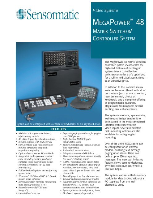
The MegaPower <strong>48</strong> <strong>matrix</strong> <strong>switcher</strong>/<br />
<strong>controller</strong> <strong>system</strong> incorporates the<br />
high-end features of our largest<br />
<strong>system</strong>s into a cost-effective<br />
<strong>switcher</strong>/<strong>controller</strong> that’s optimized<br />
for small to mid-sized applications –<br />
at an attractive price.<br />
In addition to the standard <strong>matrix</strong><br />
<strong>switcher</strong> features offered with all of<br />
our <strong>system</strong>s (such as macro control,<br />
recorder control, choice of<br />
keyboards, and a complete offering<br />
of programmable features),<br />
MegaPower <strong>48</strong> introduces several<br />
exciting new enhancements.<br />
System can be configured with a choice of keyboards, or no keyboard at all.<br />
• Modular microprocessor-based,<br />
high-density <strong>matrix</strong><br />
• <strong>48</strong> video inputs by 16 video outputs<br />
• 8 video outputs with text overlay<br />
• Slim, vertical wall-mount design;<br />
mounts directly to any wall,<br />
anywhere in facility<br />
• Optional rack mount kit available<br />
• Integrated multi-protocol control<br />
code module provides fixed and<br />
variable-speed pan/tilt and dome<br />
control (SensorNet, RS422 and<br />
Manchester)<br />
• Full embedded <strong>system</strong> menus for easy<br />
<strong>system</strong> setup<br />
• Windows ® 95/98 and NT ® 4.0-based<br />
<strong>system</strong> setup software<br />
• Removable flash memory module for<br />
data backup without a PC<br />
• Recorder control (VCRs and<br />
Integra )<br />
• User-defined macros<br />
FEATURES<br />
• Supports paging on alarm for pagers<br />
and GSM phones<br />
• Eight flexible RS232 inputs,<br />
expandable to 32<br />
• System partitioning (inputs, outputs<br />
and keyboards)<br />
• Individual monitor tours<br />
• 64 <strong>system</strong> tours and 64 Salvos<br />
• Tour indexing allows users to specify<br />
the tour’s “starting point”<br />
• 4,096 Preset titles, 250 alarm titles<br />
• On-screen text includes video input<br />
number, monitor status, time and<br />
date, video input or Preset title, and<br />
alarm title<br />
• Year displayed as 2 or 4 characters<br />
• 25 alarm display/clearance modes<br />
• Separate alarm contact tables for 16<br />
patch panels, 192 domes, 512<br />
communications and <strong>48</strong> video loss<br />
• System passwords and priority levels<br />
• On-board <strong>system</strong> diagnostics<br />
The <strong>system</strong>’s modular, space-saving<br />
wall-mount design enables it to<br />
be installed in the most centralized<br />
location with respect to the<br />
video inputs. Several innovative<br />
rack mounting options are also<br />
available, including angled<br />
mounting.<br />
One of the unit’s RS232 ports can<br />
be configured for an external<br />
modem, enabling text message<br />
paging upon alarm. Users can<br />
define up to 250 unique text<br />
messages. The new tour indexing<br />
feature allows users to designate,<br />
by video input number, where a<br />
tour will begin.<br />
The <strong>system</strong> features a flash memory<br />
module for data backup without a<br />
PC (separate from the main<br />
electronics unit).
FEATURES<br />
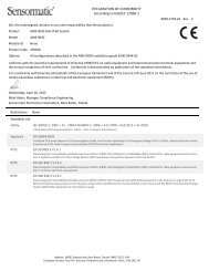
Slim, Vertical Wall-Mount Design<br />
MegaPower <strong>48</strong> has a unique, space-saving, wall-mount design that<br />
enables it to be installed in the most centralized location with respect<br />
to the video inputs. Because the <strong>system</strong> does not have to be rack<br />
mounted in a control room, it can be installed anywhere in the facility<br />
(for example, in an electrical closet), saving on cabling costs. The<br />
optional rack mount kit allows for several different mounting methods,<br />
including angled mounting.<br />
System Configuration<br />
Modular, high-density <strong>system</strong>s with <strong>48</strong> video inputs and 16 video<br />
outputs (eight of which have text overlay). Users can choose from the<br />
AD2088 Full System Keyboard and the ADTTE TOUCH TRACKER ®<br />
Keyboard (or a combination of both), or may elect not to have a<br />
keyboard configured with the <strong>system</strong>.<br />
Site Control<br />
Users can control fixed and variable-speed domes, pan/tilts, motorized<br />
lenses, auxiliary outputs, recorders, Presets and Patterns at suitablyequipped<br />
camera sites.<br />
System Programming<br />
On-screen menus enable you to use a keyboard (AD2079, AD2088,<br />
ADTTE) to program <strong>system</strong> features. Operators can use any of the<br />
monitors that have text overlay to program the <strong>system</strong>. In addition, the<br />
<strong>system</strong> setup software enables you to custom-configure all <strong>system</strong><br />
parameters. For use with computers running Windows 95/98 or NT 4.0,<br />
this software package provides simplified setup, archiving and retrieval<br />
of setup data, and uploading and downloading of that data to the<br />
<strong>system</strong>’s main electronics unit, all via RS232.<br />
RS232 Communications<br />
Eight ports allow standard communication with keyboards, alarm<br />
interface units, recorder control devices, computers, third party devices,<br />
a modem for text message paging, etc. Each port is individually<br />
programmable for data rates of 1200, 2400, <strong>48</strong>00, 9.6k, 19.2k, or 38.4k<br />
baud. Each port can expand to four ports with the optional AD1981<br />
port expander. This expands the maximum available RS232 ports to 32.<br />
Selectable On-screen Text<br />
Each monitor can display the date/time, video input number,<br />
16-character user-definable video input or Preset title, alarm title, and<br />
monitor status. The on-screen text uses white characters with black<br />
outline to optimize viewing on diverse contrast scenes. For increased<br />
visibility, all alarm titles appear on a color background. The user can<br />
turn the following displays on and off: video input number and<br />
monitor status, video input/Preset title, and date/time. In addition,<br />
users can incrementally adjust the horizontal/vertical positioning of<br />
on-screen text. Six date formats are provided:<br />
• MM/DD/YY<br />
• MM/DD/YYYY<br />
• DD/MM/YY<br />
• DD/MM/YYYY<br />
• YY/MM/DD<br />
• YYYY/MM/DD<br />
Macro Control<br />
The <strong>system</strong>’s powerful macros allow each operator to customize his or<br />
her own workstation to perform a multitude of tasks via simple, easy to<br />
remember keystrokes that are intuitive to that operator. Up to 1000<br />
macros can be divided over the eight user-defined macro keys. And<br />
each macro can be a shortcut for up to 21 keystrokes. Once macros<br />
have been programmed for a keyboard, that set of macros is stored<br />
locally. Each keyboard can be programmed differently to accommodate<br />
individual user preferences, needs and requirements. Alternatively, a set<br />
of macros can also be “copied” from one keyboard to another. Macros<br />
allow for unsurpassed ease of use, even with the most complex and<br />
demanding installations.<br />
Recorder Control<br />
Users can control all of the standard recorder functions directly from<br />
any AD2088 keyboard — play, stop, pause, record, rewind, fast forward<br />
and eject — for both VCRs and digital recorders.<br />
Pseudo Camera Numbers<br />
For each video input, users can assign a four-digit number to replace<br />
the default video input number. This can aid operators in identification,<br />
such as in the case of multiple level buildings.<br />
Monitor Tours<br />
A Tour is comprised of a sequence of up to 64 video inputs. Users can<br />
define a Tour for any video output at any time. The same video input<br />
may be inserted multiple times in the same Tour. Tours can be run<br />
forward or in reverse. Video inputs partitioned from a monitor are<br />
automatically skipped.<br />
System Tours<br />
Sixty-four Tours of video inputs or Salvos may be established for callup<br />
to monitors at any time. Each Tour provides 64 positions for<br />
insertion of video inputs — each with an individual dwell time, a<br />
Preset, a Pattern, and an auxiliary action. Tours can be run forward or<br />
in reverse. They can include the same video input multiple times and/<br />
or multiple Presets and Patterns from a single camera. Tours can be<br />
connected together to form Sequences of more than 64 video inputs.<br />
Video inputs partitioned from a monitor are automatically skipped.<br />
“Tour indexing” enables users to designate, by video input number,<br />
where the tour will begin. The currently-displayed camera is earmarked<br />
as the starting point of the tour, and the “next” and “last” buttons<br />
operate relative to that camera.<br />
Event Timers<br />
There are 35 user-programmable times available. These times may be<br />
independently designated for multiple days of the week to<br />
automatically call up System Tours to video output(s). Event timers also<br />
enable you to activate and deactivate alarm contacts based on time of<br />
day.<br />
Salvo Switching<br />
Salvo switching allows multiple video inputs to be called<br />
simultaneously to multiple contiguous video outputs. Sixty-four<br />
individual groups (Salvos), consisting of up to 16 video inputs (each<br />
with a Preset, Pattern, and/or auxiliary action), can be called either<br />
manually or as part of a System Tour.<br />
Automatic Alarm Callup<br />
Alarm inputs can be programmed to call any video input or group of<br />
video inputs (Salvo) to any one or more video outputs. For each alarm<br />
input, users can define a camera, Preset, Pattern, text message page,<br />
Salvo, alarm message, and/or auxiliary action (and an individual dwell<br />
time for each to accommodate sequencing alarms). Any combination of<br />
25 alarm display/clearance methods may be selected independently for<br />
each video output.<br />
Dedicated Alarm Contact Tables for Integration<br />
The <strong>system</strong> provides separate alarm contact tables for the different<br />
types of alarms the <strong>system</strong> can accommodate (i.e., 16 patch panels, 192<br />
domes, 512 communications, <strong>48</strong> video loss). Alarms are broken down<br />
by physical categories, so it’s easy for the installer to know where a<br />
potential alarm is generated from, making for easier programming.<br />
These dedicated alarm programming options allow for seamless<br />
integration to peripheral devices, such as access control <strong>system</strong>s. Ten<br />
monitor/contact association tables are available for inclusion in the 35<br />
event timers to activate/deactivate alarm inputs.<br />
Alarm Display Modes<br />
The alarm display mode is user-selectable for each video output.<br />
• Hold: Displays initial alarm until cleared. Queues subsequent alarms.<br />
• Sequence: Sequences multiple alarms with individual dwell times<br />
until cleared.<br />
• Sequence and Display: Displays initial alarm on one video output<br />
until alarm is cleared. Subsequent alarms are sequenced on the next<br />
video output (while they are active).<br />
• Block Hold: Alarms are displayed on blocks (groups) of contiguous<br />
video outputs. A block may consist of up to 16 contiguous monitors.<br />
Multiple blocks can be defined.<br />
• Block Sequence: Alarms are sequenced on blocks (groups) of<br />
contiguous video outputs. A block may consist of up to 16<br />
contiguous monitors. Multiple blocks can be defined.<br />
Alarm Clearance Methods<br />
The alarm clearance method is user-selectable for each video output.<br />
• Manual: Removes an alarm only after the alarm has been manually<br />
acknowledged by an operator.<br />
• Clear: Automatically removes an alarm approximately 20 seconds<br />
after the alarm input deactivates (if the alarm has not already been<br />
manually acknowledged). As a security measure, manual<br />
acknowledgment may be disabled.<br />
• Instant Clear: Automatically removes an alarm when an input<br />
deactivates (if the alarm has not already been manually<br />
acknowledged). As a security measure, manual acknowledgment<br />
may be disabled.
Indoor Mounting Options<br />
FEATURES, continued<br />
Status Output<br />
System status output (via an RS232 printer port) may be programmed to<br />
output both occurrence of, and clearance of, all alarms, as well as<br />
power status and monitor messages. An alarm event message includes<br />
date/time of event, type of alarm, contact number, video input number,<br />
and alarm status.<br />
System Partitioning<br />
System flexibility is further enhanced by defining authorized access to<br />
keyboards, video inputs and video outputs. System partitioning<br />
includes the following:<br />
• Keyboard-to-Monitor Access: Restricts selected keyboards from<br />
accessing selected video outputs.<br />
• Monitor-to-Camera Access: Restricts selected video outputs from<br />
displaying selected video inputs.<br />
• Keyboard-to-Camera Access: Restricts selected keyboards from calling<br />
or controlling selected video inputs.<br />
• Keyboard-to-Camera Control Access: Allows selected keyboards to<br />
view certain cameras, but restricts those keyboards from controlling<br />
the cameras.<br />
Password and Priority Operation<br />
Keyboards or users can be assigned one of eight levels of priority<br />
control of remote camera sites. Up to 64 user codes, each with a<br />
unique password, can be assigned to operators. Access to certain<br />
<strong>system</strong> features may be restricted depending on a user’s priority level.<br />
Internal Video Loss Detection<br />
Video loss detection is standard on all video inputs. Upon video loss, a<br />
<strong>system</strong> alarm is generated. The <strong>system</strong>’s programmable video loss<br />
detection feature means that if a camera unexpectedly loses video, a<br />
second camera in the same vicinity will automatically call up a Preset<br />
of the first camera’s field of view, ensuring that video coverage is<br />
never lost. Enabling video loss detection eliminates video output 16.<br />
On-Board Diagnostics<br />
The <strong>system</strong>’s built-in diagnostics allow the user to determine the status<br />
of the <strong>system</strong>’s internal components.<br />
Flash Memory Module for Data Backup<br />
The MegaPower <strong>48</strong> hardware contains a flash memory module for<br />
automatic data backup, without the need for a PC. This module is<br />
separate from the main electronics unit (MEU). This means that a<br />
<strong>system</strong> can be replaced and have all its data restored in less than one<br />
minute.<br />
Text Message Paging On Alarm<br />
In the event of an alarm, MegaPower <strong>48</strong> can transmit text message<br />
pages to pagers and GSM phones. These pages will instantaneously<br />
alert users of the alarm, and can provide a detailed description of the<br />
alarm, as well as instructions for how to respond to the alarm — even<br />
if the user is off-site. Users can define up to 250 unique text messages<br />
that can be transmitted to pagers and GSM phones anywhere in the<br />
world. The paging feature supports the TAP protocol<br />
OPTIONAL ACCESSORIES<br />
For more information on these accessories and equipment,<br />
refer to the individual data sheets.<br />
AD2088, AD2088R, AD2088-1, AD2088R-1 Keyboards<br />
Full <strong>system</strong> keyboards allow for video switching, pan/tilt control, dome<br />
control, auxiliary control, macro control, recorder control, and <strong>system</strong><br />
programming. The keyboards support bi-directional communication<br />
with the CPU via RS-232 ASCII commands.<br />
AD2079, AD2079R, AD2079-1, AD2079R-1, ADTTE<br />
Keyboards<br />
Full <strong>system</strong> keyboards allow for video switching, pan/tilt control, dome<br />
control, auxiliary control, and <strong>system</strong> programming. The keyboards<br />
support bi-directional communication with the <strong>system</strong> CPU via RS-232<br />
ASCII commands.<br />
AD1981, AD1981X Port Expander<br />
Expands one RS-232 port on a <strong>system</strong> into four ports. This provides<br />
connections to multiple <strong>system</strong> keyboards.<br />
AD1691, AD1691-1 Manchester Code Distributor<br />
The distributor interfaces with the <strong>matrix</strong> <strong>switcher</strong>/<strong>controller</strong> <strong>system</strong> via<br />
the Manchester port to provide 64 Manchester code outputs for use by<br />
receiver/drivers and suitably-equipped pan/tilts and domes.<br />
AD2096A, AD2096-1 Alarm Interface<br />
Supervises up to 64 alarm inputs and provides RS-232 ASCII alarm<br />
commands to the <strong>system</strong>. Alarm inputs can be programmed to call any<br />
video input, display any preset, or to initiate any auxiliary action. Up to<br />
8 units can be cascaded on a single RS-232 line.<br />
AD2031, AD2031-1 Switcher Follower<br />
Activates relays when designated video inputs are called to designated<br />
video outputs. It interfaces with the <strong>matrix</strong> <strong>switcher</strong>/<strong>controller</strong> <strong>system</strong><br />
and provides up to 32 Form A relays, via Manchester, that can be<br />
grouped in series and addressed to a single video output, or in two<br />
groups of 16 relays for two specific video outputs.<br />
AD2032, AD2032-1 Alarm Responder<br />
Activates relays when associated video outputs are in their alarming<br />
condition. Interfaces with <strong>matrix</strong> <strong>switcher</strong>/<strong>controller</strong>s and provides up<br />
to 32 Form A relays via Manchester. Multiple units can be<br />
cascaded together.<br />
AD2033, AD2033-1 Auxiliary Follower<br />
Activates relays when a specific auxiliary is triggered (either manually<br />
or automatically) for an associated video input. Interfaces with <strong>matrix</strong><br />
<strong>switcher</strong>/<strong>controller</strong>s and provides up to 32 Form A relays via<br />
Manchester. Multiple units can be cascaded together.<br />
AD1683, AD1683-X Manchester Code PSK Modem<br />
Controls up to eight receiver/drivers over telephone lines or similar<br />
audio-type link. Two AD1683 series PSK modems are required per<br />
link. A modem in transmit mode converts Manchester control code for<br />
the receiver/drivers from the <strong>switcher</strong>/<strong>controller</strong> to the PSK signals. At<br />
the remote location, a modem converts the PSK signals back to<br />
Manchester control code for the receiver/drivers.<br />
AD1983, AD1983X Code Converter<br />
Converts Manchester code to two bytes of RS-232 control code for<br />
transmission on standard RS-232 links. RS-232 receiver/drivers may be<br />
connected directly to the link (a separate RS-232 distributor may be<br />
required), or a receiving AD1983 Code Converter may be used to<br />
convert the signal back to Manchester code for use by standard<br />
receiver/drivers.<br />
Recorder Control Devices<br />
The series of recorder control devices allow for remote control of VCRs<br />
and digital recorders via the AD2088 Full System Keyboard. This<br />
enables users to have integrated control of the most popular types of<br />
recorders.<br />
• The AD100XA/AD100XA-1 Recorder Controller is the CPU of the<br />
recorder interface network. Just one recorder <strong>controller</strong> can<br />
accommodate the entire network, and it enables the programming of<br />
the various recorder control devices.<br />
• The AD100IR16/AD100IR16-1 IR Interface Module controls any<br />
recorder that has IR capability and is supplied with an IR remote<br />
(used to learn the IR commands).<br />
• The AD100RL8/AD100RL8-1 Resistive Ladder Module controls<br />
recorders that can be controlled via resistive ladder.<br />
• The AD100RS8/AD100RS8-1 RS232 Module controls RS232 VCRs<br />
and digital recorders (such as Integra).<br />
VR<strong>48</strong>RKIT Rack Mount Kit<br />
This enables the MegaPower <strong>48</strong> <strong>system</strong> to be rack mounted in a<br />
standard 19-inch EIA rack mount.<br />
VRCMKIT Cable Brackets<br />
Each kit contains three additional cable management brackets.
Prog On<br />
User<br />
O f<br />
Run<br />
Hold<br />
Site<br />
Salvo<br />
Last Next<br />
Clear<br />
F1<br />
F2<br />
Mon Arm<br />
0<br />
On<br />
Lock<br />
Pswd<br />
Pa tern<br />
Config<br />
Menu<br />
Iris<br />
Ack<br />
Enter<br />
Exit<br />
Close Open<br />
PG-UP PG-DN<br />
+<br />
-<br />
SPECIFICATIONS<br />
Product Codes<br />
Each MegaPower <strong>48</strong> <strong>system</strong> consists of a wall mount assembly<br />
(bracket and patch panel assembly), the main electronics unit (NTSC<br />
or PAL specified at time of order), pre-wired transformer assembly<br />
(USA or International), and documentation kit in specified language<br />
(choice of six languages). In addition, users can specify keyboard of<br />
preference via the product code:<br />
VR<strong>48</strong>NC ........................................ MegaPower <strong>48</strong> configured without<br />
a keyboard<br />
VR<strong>48</strong>TT ......................................... MegaPower <strong>48</strong> configured with<br />
ADTTE TOUCH TRACKER<br />
Keyboard<br />
VR<strong>48</strong>KB ......................................... MegaPower <strong>48</strong> configured with<br />
AD2088 Full-System Keyboard<br />
General<br />
Bandwidth ...................................... 10 MHz<br />
Frequency Response .................... ± 1.0 dB to 6 MHz<br />
S/N Ratio ....................................... -60 dB (Vp-p vs. Vrms noise)<br />
Crosstalk<br />
Adjacent Channels .................... -55 dB (at 3.58 MHz)<br />
Input to Input ............................. -70 dB (at 3.58 MHz)<br />
Differential Delay ........................... ± 1.0˚<br />
Differential Phase .......................... ≤ 0.5˚<br />
Differential Gain ............................ ≤ 1.5%<br />
Tilt .................................................. ≤ 2.0%<br />
Gain ............................................... Unity ± 1 dB<br />
Return Loss (Input/Output) ........... ≥ 40 dB<br />
DC Level (Video Signal) ................ 0 Volts<br />
Switching ....................................... Complete switching of crosspoint<br />
<strong>matrix</strong>. EIA RS-170 and NTSC,<br />
CCIR and PAL<br />
Switching Speed ........................... Less than 20 ms (typical)<br />
Phase Adjustment ......................... 180˚ Vertical interval adjustment<br />
for switching bay<br />
Non-Volatile Memory ..................... Setup information saved for a<br />
minimum of five years<br />
On-Screen Text ............................. Date/Time, Video Input Number,<br />
Video Input or Preset Title<br />
(16 characters), Monitor Status,<br />
Alarm Title (<strong>48</strong> characters)<br />
Character Set ................................ English, French, Italian, German,<br />
Spanish, Portuguese<br />
Electrical<br />
Power Source ................................ 24 VAC external transformer<br />
Supply Voltage .............................. 90-132 VAC, 47-63 Hz<br />
195-253 VAC, 47-63 Hz<br />
Power Requirements..................... 20 watts maximum<br />
Relay Outputs ............................... Two Form-C relays through two<br />
3-pin terminal screw connectors<br />
Power ............................................ One 3-pin terminal screw connector<br />
Flash Memory Module .................. One 8-pin header<br />
SensorNet ..................................... Six ports through terminal screw<br />
connectors<br />
Daisychain<br />
Manchester ................................ 3 domes at a maximum distance of<br />
1,500 meters (5,000 ft) on one 18<br />
AWG shielded twisted pair (STP)<br />
SEC RS422 ............................... 10 domes at a maximum distance<br />
of 1 Km (3,000 ft) on two 22 AWG<br />
shielded twisted pairs (STP)<br />
SensorNet .................................. 32 devices at a maximum distance<br />
of 1 Km (3000 ft) on one 22 AWG<br />
unshielded twisted pair (UTP)<br />
Mechanical<br />
Mounting ........................................ Vertical wall or 19-inch EIA rack<br />
mount<br />
Dimensions (H x W x D) ................ 50.8 x 43.8 x 8.9 cm<br />
(20 x 17.3 x 3.5 in)<br />
Unit Weight<br />
Wall Bracket .............................. 1.54 Kg (3.4 lbs)<br />
Patch Panel Assembly .............. 1.72 Kg (3.8 lbs)<br />
Main Electronics Unit ................ 2.72 Kg (6.0 lbs)<br />
Total ........................................... 5.97 Kg (13.2 lbs)<br />
Transformer Weight ....................... 2.17 Kg (4.8 lbs)<br />
Color .............................................. Black<br />
Environmental<br />
Operating Temperature ................. 0˚ to 50˚C (32˚ to 122˚F)<br />
Humidity ........................................ 5-95% RH (non-condensing)<br />
Storage Temperature .................... -40˚ to 70˚C (-40˚ to 155˚F)<br />
Regulatory<br />
Emissions ...................................... FCC Part 15, Class A<br />
Safety ............................................ UL1950<br />
IEC90, EN60950, EN55022,<br />
EN50130-4 UL or CSA CS 22.2,<br />
No. 950-95<br />
Integra <br />
Digital Video<br />
Recorder<br />
Recorder Control<br />
Devices<br />
Connections<br />
Video Inputs .................................. 0.5 to 2.0 Vp-p, BNC composite<br />
Video Outputs ................................ 1.0 Vp-p, BNC composite<br />
RS-232 .......................................... Eight 8-Pin Modular RJ-45 jacks<br />
(expandable)<br />
Optional Port Expander extends<br />
each RS-232 port to four<br />
(32 ports max.)<br />
Modem ........................................... One DB9 connector<br />
RS-422 .......................................... Six ports through terminal<br />
screw connector<br />
Manchester .................................... One port through terminal<br />
screw connector<br />
Alarm Inputs .................................. 16 inputs through two 16-pin<br />
terminal screw connectors<br />
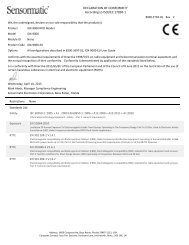
Programmable<br />
Dome<br />
Camera<br />
Monitor<br />
1 2 3<br />
4 5 6<br />
7 8 9<br />
Auxiliary PG-LEFT<br />
O f<br />
PG-RIGHT<br />
Shot<br />
ADTTE<br />
TOUCH TRACKER ®<br />
Keyboard<br />
MegaPower <strong>48</strong><br />
Matrix Switcher/<br />
Controller System<br />
Alarm<br />
Input<br />
Pager<br />
PTZ<br />
Specifications and availability subject to<br />
improvement or change without notice.<br />
AD2088<br />
Full System<br />
Keyboard<br />
Certain product names mentioned herein may be trade<br />
names and/or registered trademarks of other companies.<br />
©2001 Sensormatic Electronics Corporation VSD017-01-C 02/01 L