TYPICAL CUTTING-IN SLEEVE INSTALLATIONS ... - Tyler Union
TYPICAL CUTTING-IN SLEEVE INSTALLATIONS ... - Tyler Union
TYPICAL CUTTING-IN SLEEVE INSTALLATIONS ... - Tyler Union

You also want an ePaper? Increase the reach of your titles
YUMPU automatically turns print PDFs into web optimized ePapers that Google loves.
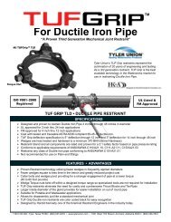
MECHANICAL JO<strong>IN</strong>T C153 DUCTILE IRON<br />
COMPACT FITT<strong>IN</strong>GS<br />
Sizes 3" thru 12" UL Listed For Fire Main Equipment<br />
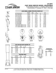
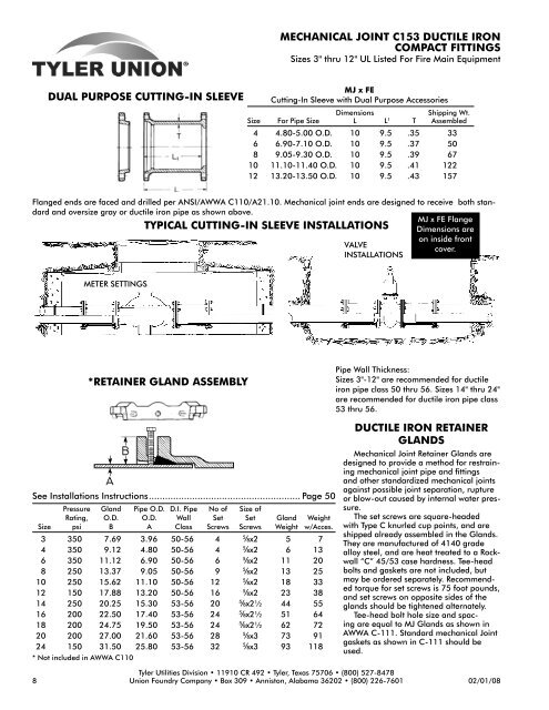
DUAL PURPOSE <strong>CUTT<strong>IN</strong>G</strong>-<strong>IN</strong> <strong>SLEEVE</strong><br />
MJ x FE<br />
Cutting-In Sleeve with Dual Purpose Accessories<br />
Dimensions<br />
Shipping Wt.<br />
Size For Pipe Size L L 1 T Assembled<br />
4 4.80-5.00 O.D. 10 9.5 .35 33<br />
6 6.90-7.10 O.D. 10 9.5 .37 50<br />
8 9.05-9.30 O.D. 10 9.5 .39 67<br />
10 11.10-11.40 O.D. 10 9.5 .41 122<br />
12 13.20-13.50 O.D. 10 9.5 .43 157<br />
Flanged ends are faced and drilled per ANSI/AWWA C110/A21.10. Mechanical joint ends are designed to receive both standard<br />
and oversize gray or ductile iron pipe as shown above.<br />
MJ x FE Flange<br />
<strong>TYPICAL</strong> <strong>CUTT<strong>IN</strong>G</strong>-<strong>IN</strong> <strong>SLEEVE</strong> <strong>IN</strong>STALLATIONS Dimensions are<br />
on inside front<br />
VALVE<br />
cover.<br />
<strong>IN</strong>STALLATIONS<br />
METER SETT<strong>IN</strong>GS<br />
*RETA<strong>IN</strong>ER GLAND ASSEMBLY<br />
Pipe Wall Thickness:<br />
Sizes 3"-12" are recommended for ductile<br />
iron pipe class 50 thru 56. Sizes 14" thru 24"<br />
are recommended for ductile iron pipe class<br />
53 thru 56.<br />
See Installations Instructions........................................................ Page 50<br />
Pressure Gland Pipe O.D. D.I. Pipe No of Size of<br />
Rating, O.D. O.D. Wall Set Set Gland Weight<br />
Size psi B A Class Screws Screws Weight w/Acces.<br />
3 350 7.69 3.96 50-56 4 Á x2 5 7<br />
4 350 9.12 4.80 50-56 4 Á x2 6 13<br />
6 350 11.12 6.90 50-56 6 Á x2 11 20<br />
8 250 13.37 9.05 50-56 9 Á x2 13 25<br />
10 250 15.62 11.10 50-56 12 Á x2 18 33<br />
12 150 17.88 13.20 50-56 16 Á x2 23 38<br />
14 250 20.25 15.30 53-56 20 Á x2½ 44 55<br />
16 200 22.50 17.40 53-56 24 Á x2½ 51 64<br />
18 200 24.75 19.50 53-56 24 Á x2½ 62 72<br />
20 200 27.00 21.60 53-56 28 Á x3 73 91<br />
24 150 31.50 25.80 53-56 32 Á x3 93 118<br />
* Not included in AWWA C110<br />
DUCTILE IRON RETA<strong>IN</strong>ER<br />
GLANDS<br />
Mechanical Joint Retainer Glands are<br />
designed to provide a method for restraining<br />
mechanical joint pipe and fittings<br />
and other standardized mechanical joints<br />
against possible joint separation, rupture<br />
or blow-out caused by internal water pressure.<br />
The set screws are square-headed<br />
with Type C knurled cup points, and are<br />
shipped already assembled in the Glands.<br />
They are manufactured of 4140 grade<br />
alloy steel, and are heat treated to a Rockwall<br />
“C” 45/53 case hardness. Tee-head<br />
bolts and gaskets are not included, but<br />
may be ordered separately. Recommended<br />
torque for set screws is 75 foot pounds,<br />
and set screws on opposite sides of the<br />
glands should be tightened alternately.<br />
Tee-head bolt hole size and spacing<br />
are equal to MJ Glands as shown in<br />
AWWA C-111. Standard mechanical Joint<br />
gaskets as shown in C-111 should be<br />
used.<br />
<strong>Tyler</strong> Utilities Division • 11910 CR 492 • <strong>Tyler</strong>, Texas 75706 • (800) 527-8478<br />
8 <strong>Union</strong> Foundry Company • Box 309 • Anniston, Alabama 36202 • (800) 226-7601 02/01/08
DUCTILE IRON C110 FULL BODY<br />
MECHANICAL JO<strong>IN</strong>T FITT<strong>IN</strong>GS<br />
*RETA<strong>IN</strong>ER GLAND ASSEMBLY<br />
See Installations Instructions........................................................ Page 50<br />
Pressure Gland Pipe O.D. D.I. Pipe No of Size of<br />
Rating, O.D. O.D. Wall Set Set Gland Weight<br />
Size psi B A Class Screws Screws Weight w/Acces.<br />
3 350 7.69 3.96 50-56 4 Á x2 4 8<br />
4 350 9.12 4.80 50-56 4 Á x2 5 11<br />
6 350 11.12 6.90 50-56 6 Á x2 9 16<br />
8 250 13.37 9.05 50-56 9 Á x2 13 21<br />
10 250 15.62 11.10 50-56 12 Á x2 17 26<br />
12 150 17.88 13.20 50-56 16 Á x2 20 28<br />
14 250 20.25 15.30 53-56 20 Á x2½ 44 55<br />
16 200 22.50 17.40 53-56 24 Á x2½ 54 64<br />
18 200 24.75 19.50 53-56 24 Á x2½ 62 72<br />
20 200 27.00 21.60 53-56 28 Á x3 76 91<br />
24 150 31.50 25.80 53-56 32 Á x3 103 118<br />
* Not included in AWWA C110<br />
Pipe Wall Thickness:<br />
Sizes 3"-12" are recommended for ductile<br />
iron pipe class 50 thru 56. Sizes 14" thru<br />
24" are recommended for ductile iron pipe<br />
class 53 thru 56.<br />
DUCTILE IRON RETA<strong>IN</strong>ER<br />
GLANDS<br />
Mechanical Joint Retainer Glands are<br />
designed to provide a method for restraining<br />
mechanical joint pipe and fittings<br />
and other standardized mechanical joints<br />
against possible joint separation, rupture<br />
or blow-out caused by internal water pressure.<br />
The set screws are square-headed<br />
with Type C knurled cup points, and are<br />
shipped already assembled in the Glands.<br />
They are manufactured of 4140 grade<br />
alloy steel, and are heat treated to a Rockwall<br />
“C” 45/53 case hardness. Tee-head<br />
bolts and gaskets are not included, but<br />
may be ordered separately. Recommended<br />
torque for set screws is 75 foot pounds,<br />
and set screws on opposite sides of the<br />
glands should be tightened alternately.<br />
Tee-head bolt hole size and spacing<br />
are equal to MJ Glands as shown in<br />
AWWA C-111. Standard mechanical Joint<br />
gaskets as shown in C-111 should be<br />
used.<br />
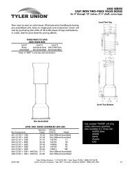
TEES<br />
MJ GLAND<br />
MJ x MJ x Swivel<br />
Dimensions<br />
Size X Y Weight<br />
6 8.0 10.5 150<br />
8x6 9.0 11.5 199<br />
8 9.0 11.5 210<br />
10x6 11.0 13.5 267<br />
12x6 12.0 14.5 346<br />
16x6 15.0 17.5 619<br />
16x8 15.0 17.5 649<br />
30x6 18.0 24.5 2070<br />
All weights shown include the Swivel Gland<br />
Size<br />
Gland Weight<br />
Wt. Pack Gland Only<br />
2 5 3<br />
3 7 4<br />
4 10 6<br />
6 16 10<br />
8 25 16<br />
10 30 19<br />
12 40 26<br />
14 45 34<br />
16 55 54<br />
18 65 52<br />
20 85 73<br />
24 105 91<br />
30 220 90<br />
36 301 127<br />
ANSI/AWWA C110/A21.10, ANSI/AWWA C111/A21.11<br />
<strong>Tyler</strong> Utilities Division • 11910 CR 492 • <strong>Tyler</strong>, Texas 75706 • (800) 527-8478<br />
20 <strong>Union</strong> Foundry Company • Box 309 • Anniston, Alabama 36202 • (800) 226-7601 02/01/08
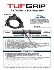
assembly instructions<br />
ADAPTER FLANGE<br />
FM APPROVED<br />
Wall Thickness Note:<br />
Recommended for ductile<br />
iron pipe Class 53 thru<br />
Class 56.<br />
1. Place adapter flange and MJ gasket over the plain end of the<br />
pipe with the small side of the MJ gasket facing the flange<br />
side of the adapter flange.<br />
2. Place the pipe end against flange to be joined and slip the<br />
MJ gasket into position against the flange. Make sure the<br />
gasket is evenly seated against the flange.<br />
3. Slide adapter flange into position against the small (tapered) side of the MJ gasket and align the bolt holes.<br />
Insert the bolts and finger tighten the nuts to maintain position and alignment.<br />
4. Snug up all nuts evenly. Alternating @ 180°, tighten the nuts to a torque of: 3" - 60 foot pounds; 4" thru 12"<br />
- 90 foot pounds.<br />
5. Snug up all set screws evenly around the pipe. Tighten the Torque Head Set Screws evenly, alternating at 180<br />
degrees.<br />
NOTE: THE TORQUE HEAD TOP WILL BREAK OFF AT THE RECOMMENDED SETT<strong>IN</strong>G OF 80-90 FT. LBS.<br />
MAXIMUM DEFLECTION OF JO<strong>IN</strong>T ( 2°)<br />
RETA<strong>IN</strong>ER GLAND<br />
Pipe Wall Thickness: Sizes 3"-12" are recommended for ductile<br />
iron pipe class 50 thru 56. Sizes 14" thru 24" are recommended<br />
for ductile iron pipe class 53 thru 56.<br />
1. Wash bell and plain end with soapy water, then slip<br />
gland and gasket over plain end with the small side of<br />
the gasket and ring side of of the gland facing the bell.<br />
2. Slip plain end into bell. Brush soapy water on gasket.<br />
This lubricates the gasket and allows it to slip easily<br />
into place. Push gasket into bell making sure it is<br />
evenly in the bell gasket landing.<br />
3. Slide the gland into position against the back of the<br />
gasket. Align bolt holes, insert T-bolts and tighten nuts<br />
to finger tight.<br />
4. Snug up all T-bolt nuts evenly. Alternating at 180°,<br />
tighten the T-bolt nuts to a torque of:<br />
3" - 60 foot pounds 4" thru 24" - 90 foot pounds.<br />
5. Snug up all set screws evenly. Using a torque wrench, tighten the set screws alternating at 180° to the<br />
recommended torque value of 75 foot pounds. If required double check set screws immediately.<br />
Maximum recommended deflection of joints:<br />
3" thru 12"-2°; 14" thru 30" - 1°<br />
<strong>Tyler</strong> Utilities Division • 11910 CR 492 • <strong>Tyler</strong>, Texas 75706 • (800) 527-8478<br />
48 <strong>Union</strong> Foundry Company • Box 309 • Anniston, Alabama 36202 • (800) 226-7601 02/01/08