Manual - UEi Automotive
Manual - UEi Automotive
Manual - UEi Automotive

Create successful ePaper yourself
Turn your PDF publications into a flip-book with our unique Google optimized e-Paper software.
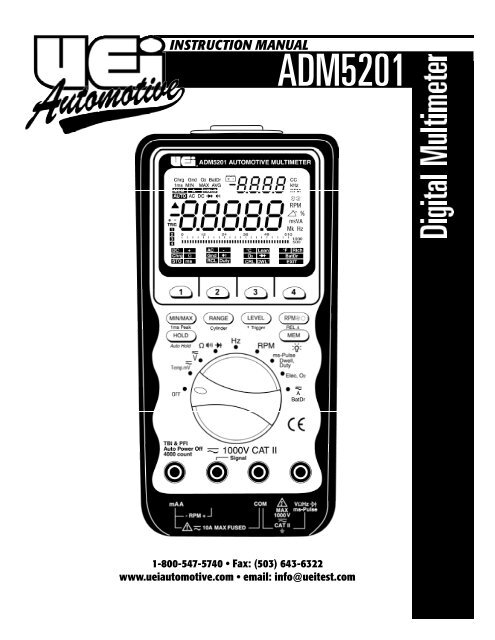
INSTRUCTION MANUAL<br />
ADM5201<br />
1-800-547-5740 • Fax: (503) 643-6322<br />
www.ueiautomotive.com • email: info@ueitest.com
Introduction<br />
The ADM5201 advanced handheld automotive multimeter combines all<br />
the features of a full function multimeter and integrates the functions of<br />
an O2 Sensor tester, PFI & TBI Fuel Injection testers. The ADM5201<br />
provides a quick and accurate diagnosis of the complete O2 circuit. It is<br />
also capable of sending a Rich/Lean signal to the ECM, and displaying<br />
crossing-per-second (CC) and O2 voltage simultaneously, when secondary<br />
display shows test results. This professional grade multimeter provides<br />
efficient trouble shooting solutions to the most difficult problems<br />
encountered in today’s sophisticated automotive electronic systems.<br />
The ADM5201 has a bright LED backlight. A battery access door allow s<br />
users to replace the battery and fuse without breaking ca l i b ration seals!<br />
High impact over-molded case absorbs shock over more of the case than a<br />
conventional rubber boot design. Convenient closed case ca l i b ration<br />
a l l ows adjustments to be made directly through the Optica l l y - I s o l a t e d<br />
RS 232 serial port.<br />
Features include<br />
• Testing functions include: O2 Sensor Test, Ground Test, Battery and<br />
Alternator Charging System Test, and Battery Drain Test<br />
• Accurate RPM measurements for 2 and 4 stroke automotive<br />
engines with 1 to 12 cylinders using the inductive pickup<br />
• ms-Pulse Width function to test on-time of both PFI type and TBI<br />
type fuel injectors<br />
• Duty Cycle and direct DWELL reading<br />
• 4 step adjustable triggers on 1 to 12 cylinders<br />
• Temperature measurement up to 2,372˚F or 1,300˚C<br />
• 4-4/5 digit, 50,000 count primary and 9,999 count secondary dual<br />
display with bar-graph (Frequency range: 99,999 counts)<br />
• Backlit display<br />
• RS-232C optically isolated serial port<br />
• Memory store and recall (20 locations)<br />
• Auto hold. 50ms high speed MIN/MAX/Avg, & relative mode<br />
• 1ms Peak Mode<br />
• Auto-power off<br />
• High impact over-molded case<br />
Safety Notes<br />
Before using this meter, read all safety information carefully. In<br />
this manual the word "WARNING" is used to indicate conditions<br />
or actions that may pose physical hazards to the user. The word<br />
"CAUTION" is used to indicate conditions or actions that may<br />
damage this instrument.<br />
• DO NOT attempt to use this meter if either the meter or the test<br />
leads have been damaged. Send unit in for repair by a qualified<br />
repair facility<br />
• Test leads must be fully inserted prior to taking measurements<br />
• Never attempt a voltage measurement with the test leads inserted<br />
into the “A” terminal and the “C OM” terminal - The “A” terminal is<br />
protected by a fuse. You might be injured or damage the meter<br />
• Always disconnect the live test lead before disconnecting the<br />
common test lead from a circuit<br />
• Turn the engine off before connecting or disconnecting inductive<br />
pickup to avoid a shock.<br />
• Disconnect the test leads from the test points before changing<br />
functions to avoid damaging the meter when testing above 350V AC<br />
• Choose the proper range and function for the measurement -<br />
Always set the meter to the highest range and work downward for<br />
an unknown value if you are using manual ranging mode<br />
• Do not try voltage or current measurements that may exceed the<br />
ratings marked on the input limit for switch or terminal<br />
• Use current probes to measure circuits exceeding 10A<br />
• Disconnect the “LIVE” test lead before disconnecting the<br />
“COMMON” test lead<br />
• Do not test a recently recharged lead-acid battery<br />
• Disconnect the power and discharge all high-voltage capacitors<br />
before testing in the resistance, continuity, and diode functions<br />
• If the engine has been running, do not place the meter and its<br />
accessories near the engine or the exhaust manifold which might<br />
be hot and can damage the meter<br />
• If any of the following indications occur during testing, turn<br />
off the power source to the circuit under test:<br />
• Arcing<br />
• Flame<br />
• Smoke<br />
• Extreme Heat<br />
• Smell of Burning Materials<br />
• Discoloration or Melting of Components<br />
• Read the safety precautions associated with the equipment being<br />
tested and seek assistance or advice when performing<br />
unfamiliar tasks.<br />
• Keep your fingers away from the test lead metal probe contacts<br />
and bus-bars when making measurements. Always grip the<br />
instrument and test-leads behind the hand guards (molded into<br />
the probes).<br />
• In the event of electrical shock, ALWAYS bring the victim to<br />
the emergency room for evaluation, regardless of the victim’s<br />
apparent recovery. Electrical shock can cause an unstable heart<br />
rhythm that may need medical attention.<br />
WARNING!<br />
Exceeding the specified limits of this meter is dangerous and can<br />
expose the user to serious or possibly fatal injury.<br />
International Symbols<br />
• DO NOT attempt to measure any voltage that exceeds 600 volts<br />
with this meter - <strong>UEi</strong> offers numerous alternatives for measuring<br />
high voltage and current<br />
• Voltages above 600 volts DC or 25 volts AC may constitute a<br />
serious shock hazard<br />
ADM5201-MAN P. 1
14<br />
C o n t rols and Indicators<br />
1<br />
12. MIN/MAX : Press this push-button momentarily to activate Record<br />
1ms Peak function. Press this push-button for more than 1<br />
second to activate 1 ms Peak function.<br />
RANGE<br />
13. : Press this push-button momentarily to select ranges<br />
Cylinder<br />
PFI/TBI<br />
in the manual ranging mode of most functions or<br />
number of cylinders on Dwell function. Press this<br />
push-button momentarily to toggle between the PFI<br />
mode and the TBI mode when measuring on-time of<br />
fuel injectors.<br />
14. RS-232 Optical interface<br />
13<br />
12<br />
11<br />
2<br />
3<br />
4<br />
5<br />
LCD Display Functional Description<br />
27<br />
28 29 30 30 32 33 34<br />
6<br />
24<br />
23<br />
22<br />
21<br />
10<br />
9<br />
7<br />
8<br />
20<br />
19<br />
18<br />
17<br />
35<br />
16<br />
36<br />
1. LCD Display: 4-4/5 digit, 50000 count (primary) and 9999 count<br />
(secondary) dual display with bar-graph.<br />
15<br />
2. : On screen menu selection push-buttons.<br />
3. LEVEL : Press this push-button momentarily select levels.<br />
±Trigger Press again for more than 1 second to toggle<br />
between positive and negative trigger slopes.<br />
4. RPM : Press this push-button momentarily to toggle<br />
REL ∆ between RPM and RPM in RPM function.<br />
Press again for more than 1 second to select<br />
Relative Zero.<br />
5. MEM : Press this push-button momentarily to select Memory<br />
mode. Press again for more than 1 second to turn the<br />
LCD backlight on.<br />
6. Selector: Turn the power ON or OFF and select a function.<br />
7. COM: Common (ground reference) input terminal for all<br />
functions except RPM function.<br />
8. VΩ Hz ms Elec Temp: Input terminal for all functions except<br />
Current and RPM functions.<br />
9. PRM +/Signal: Input terminal (+) for RPM function. Output<br />
terminal for sending out a Rich command or a Lean command<br />
for 5 seconds in O2 Sensor test mode.<br />
10. A/RPM: Input terminal (+) for current function. Ground<br />
reference (-) input terminal for RPM function.<br />
11. HOLD<br />
Auto Hold<br />
: Press this push-button momentarily to activate HOLD<br />
for simply freezing a reading. Press again for more<br />
than 1 second to activate Auto Hold for automatically<br />
capturing a stable reading, beeping to acknowledge,<br />
and holding it on the LCD.<br />
15. Menu on screen<br />
16. 1 2 3 4 : These annunciators indicate trigger level status.<br />
17. + - Trig: These annunciators indicate that positive (+) or<br />
negative (-) Trigger Slope is selected.<br />
18. : This symbol indicates Negative Polarity.<br />
19. : This symbol indicates the Relative function is activated.<br />
20. DATA: Primary digital readings of data being measured.<br />
21. AUTO : This annunciator indicates Autoranging.<br />
22. AC DC: AC annunciator indicates alternating current is selected.<br />
DC annunciator indicates direct current is selected.<br />
23. MEM : This annunciator indicates the Memory function<br />
is activated.<br />
24. A- HOLD : “HOL D” annunciator indicates the HOLD function<br />
is selected and “A-” and “HOLD” annunciators indicate the Auto<br />
Hold function is selected.<br />
25. 1 ms MIN/MAX: These annunciators indicate 1 ms MAX (+)<br />
Peak, or 1 ms MIN (-) Peak reading is being displayed.<br />
26. MIN/MAX/AVG: These annunciators indicate MIN (Minimum,<br />
MAX (Maximum), or AVG (Average) reading is being displayed.<br />
27. Chrg: This annunciator indicates the Charging system test<br />
function is selected.<br />
ADM4201-MAN P. 2
28. Gnd: This annunciator indicates the Ground test function<br />
is selected.<br />
29. O2: This annunciator indicates the O2 Sensor test function<br />
is selected.<br />
30. BatDr: This annunciator indicates the Battery Drain test<br />
function is selected.<br />
31. : This symbol indicates the Diode test function is selected.<br />
32. : This symbol indicates the Continuity test function<br />
is selected.<br />
33. : Low Battery alert. Replace the battery as soon as possible<br />
to ensure accuracy.<br />
34. DATA: Secondary display for Dual Display data.<br />
35. CC... : These annunciators indicate the function being selected<br />
and/or the appropriate measurement units.<br />
36. : Analog bar-graph with scale.<br />
Operating Instructions<br />
Voltage (V)<br />
1. Set rotary selector to position. The meter defaults at DC.<br />
2. Press menu key 2 momentarily to select AC, and press<br />
twice to select Hz in the secondary display, if required.<br />
3. Insert red lead into “V” terminal and black lead into<br />
“COM” terminal.<br />
4. Touch black probe to ground or negative side of the circuit and<br />
touch red probe to positive side of the circuit coming from the<br />
power source (Fig 2).<br />
5. Set rotary selector to m position for voltage application below<br />
0.4 V with similar operation procedures.<br />
6. Refer to Dual Display RPM function.<br />
NOTE: Voltage must be measured in parellel (red probe<br />
measuring circuit from power source).<br />
The analog bar graph is easier to read when the data causes the digital<br />
display to rapidly change. It is also useful for trend setting or directional<br />
data.<br />
RPM<br />
Making Measurements and Tests<br />
All measurements and tests are made by first setting the rotary selector<br />
switch to a function setting (so that the meter is put in the default<br />
measurement function) and then selecting a measurement from the<br />
menu keys. Note that not all function knob settings have corresponding<br />
menu key settings.<br />
For example, the steps below show how to make an AC voltage<br />
measurement.<br />
1. Set the rotary selector switch to position for voltage<br />
measurements. Then, the meter is set to the default DC voltage<br />
measurement mode.<br />
2. Select the menu key 2 for AC voltage measurement (Fig 1).<br />
3. Connect the test leads to the measurement points.<br />
Parallel Connection<br />
(Fig 2)<br />
Dual Display RPM<br />
This function is available for the primary functions; DC, mV, AC mV, DC<br />
V, AC V, Dwell, ms-Pulse, and Duty Cycle. The trigger level selection is<br />
not available for this function, but available for the primary display<br />
RPM function.<br />
1. Set the meter to the corresponding primary function.<br />
(Fig 1)<br />
RPM<br />
2. Press button to toggle between RPM (for 4-stroke<br />
engine) and RPM (for 2-stroke or DIS engine).<br />
3. Insert the Dual Banana Connector into the RPM - and the RPM +<br />
input terminals as shown. Ensure the plug with the Ground Tab<br />
goes into the RPM - terminal.<br />
4. Clamp the inductive pickup to a spark plug wire with the arrow<br />
sign facing the spark plug as shown. Ensure the pickup jaws are<br />
completely closed (Fig 3).<br />
ADM5201-MAN P. 3
5. Read RPM in the secondary display.<br />
NOTE: Position the pickup as far away from the distributor and<br />
the exhaust manifold as possible. Position the pickup within 6<br />
inches of the spark plug or move it to another plug wire if no<br />
reading or an erratic reading is received.<br />
Banana plug<br />
K-type temperature probe<br />
Ground Tab<br />
Resistance (Ω)<br />
Collects under test<br />
(Fig 4)<br />
Inductive<br />
Pickup<br />
CAUTION!<br />
Turn off power and discharge all capacitors on circuit to be tested<br />
before attempting in circuit resistance measurements. Accurate<br />
measurement is not possible if external or residual voltage is present.<br />
DC 3..8 V<br />
1. Set rotary selector to “Ω “ position. The meter defaults<br />
at “Ω“ function. “OFL.” is displayed in the primary display.<br />
Spark Plug<br />
Distributor<br />
Cap<br />
(Fig 3)<br />
2. Insert black lead into “COM” terminal and red lead into<br />
“Ω“ terminal (Fig 5).<br />
3. Touch the test lead probes across the resistance or circuit to be tested.<br />
Temperature<br />
Conventional<br />
Ignition Coil<br />
1. Set rotary selector to “Temp. m “ position.<br />
2. Press menu key 3 (or 4) to select temperature function. The<br />
primary display will show “OFL.” and the secondary display will<br />
always show the meter’s internal temperature in ˚F or ˚C<br />
alternatively matching with the selected primary display mode<br />
of ˚F or ˚C.<br />
NOTE: The resistance in the test leads can affect accuracy in the<br />
500Ω range. Short the leads together and press the “REL ∆”<br />
button to automatically subtract the test lead resistance from the<br />
measured resistance.<br />
3. Insert banana plug K-type temperature bead probe with correct<br />
+/- polarities. You can also use a thermocouple probe adapter<br />
(optional accessory) to adapt other standard K-type<br />
temperature probes (Fig 4).<br />
4. Touch the end of the thermocouple probe to the measurement<br />
surface and read the primary digital display with ˚F (or ˚C). We<br />
can easily recognize the temperature unit of the primary display<br />
from the secondary display.<br />
NOTE: The measured temperature is displayed with 0.1 ˚F<br />
(or 0.1 ˚F) resolution. For example, 98˚F is displayed as 0098.0<br />
and 98˚C is displayed 0098.0.<br />
Parallel Connection<br />
ADM5201-MAN P. 4<br />
(Fig 5)
Continuity ( )<br />
CAUTION!<br />
Turn off power OFF on the test circuit. A beeper tone does not<br />
necessarily mean zero resistance.<br />
1. Set rotary selector to “Ω “ position.<br />
2. Press menu key 2 to select “Continuity” function. “OFL.” is<br />
displayed in the primary display.<br />
3. Insert black lead into “COM” terminal and red lead into<br />
“Ω“ terminal (Fig 6).<br />
4. Touch the test lead proves across the device being tested.<br />
5. The primary display shows “OFL.“ if the diode is good. Any other<br />
readings indicate the diode is resistive or shorted (defective).<br />
Use the table below to determine if the diode is good or bad.<br />
Diode Forward Bias ( ) Reverse Bias ( )<br />
Good 0.4 to 0.9 V OFL<br />
OFL<br />
0.4 to 0.9 V<br />
Bad OFL 1.0 to 3.0 V<br />
1.0 to 3.0 V OFL<br />
0.4 to 0.9 V 0.4 to 0.9 V<br />
OFL<br />
OFL<br />
0.0000 V 0.0000 V<br />
If the resistance of the device is below 70Ω, there is a continuous beep<br />
t o n e .<br />
If the resistance of the device is more than 70Ω, there is no beep tone.<br />
This is useful for checking wiring connections and operation of switches.<br />
Reverse Bias<br />
Forward Bias<br />
Frequency<br />
(Fig 7)<br />
1. Set rotary selector to “Hz” position.<br />
2. Insert black lead into “COM” terminal and read lead into<br />
“Hz” terminal.<br />
Diode (<br />
) Test<br />
(Fig 6)<br />
3. Touch black probe to ground and touch red probe to the<br />
“Signal out” wire on the sensor (Fig 8).<br />
CAUTION!<br />
Turn the power OFF on the test circuit.<br />
1. Set rotary selector to “Ω “ position.<br />
2. Press menu key 3 to select “Diode Test” function. “OFL.“ is<br />
displayed in the primary display.<br />
3. Connect the test leads as shown and observe the digital display.<br />
Normal forward voltage drop (forward biased) for a good silicon<br />
diode is between 0.4 V to 0.9 V. A reading higher than that<br />
indicates a leaky diode (defective). A zero reading indicates a<br />
shorted diode (defective). An “OFL.“ indicates an open<br />
diode (defective) (Fig 7).<br />
4. Reverse the test leads connections (reverse biased) across<br />
the diode.<br />
Ground<br />
Signal Out<br />
Electronic Voltage<br />
ADM5201-MAN (Fig 8) P. 5
RPM (primary display)<br />
WARNING!<br />
Be sure the inductive pickup is in the terminals marked “- RPM +” when<br />
measuring RPM’s. If the pickup is in the wrong terminal, personal injury<br />
or meter damage may occur.<br />
The ignition system can generate a potential shock hazard. Ensure that<br />
the engine is off before connecting or removing the inductive pickup.<br />
1. Set rotary selector to “RPM” position. The meter defaults at<br />
“TRIG<br />
1 2 3 4“ “ (trigger) level.<br />
RPM<br />
2. Press “ “ push-button to toggle between RPM for<br />
4-stroke engine and RPM for 2-stroke and DIS engine.<br />
3. Insert the Dual Banana Connector into the “RPM -” and the<br />
“RPM +” input terminals as shown. Ensure the plug with the<br />
Ground Tab goes into the “RPM -” terminal (Fig 9).<br />
4. Clamp the inductive pickup to a spark plug wire with the arrow<br />
sign facing the spark plug as shown. Ensure the pickup jaws are<br />
completely closed.<br />
5. Read RPM in the primary display.<br />
NOTE: 4 trigger levels (TRIG 1 2 3 TRIG<br />
1 2<br />
TRIG 1 TRIG 1 2 3 4 ) are selectable by pressing<br />
LEVEL button momentarily in this function.<br />
Fuel Injection On Time<br />
This function applies to both Port Fuel Injectors (PFI) which operate with<br />
a single On Time pulse and Throttle Body Injectors (TBI) which operate<br />
with twin pulses.<br />
ON TIME<br />
Port Fuel Injection Wa v e f o r m<br />
1. Set rotary selector to “ms-Pulse, Dwell, Duty” position.<br />
The meter defaults at “ms-Pulse” with - TRIG<br />
1 2 3<br />
level in<br />
the PFI mode. (“PF 1” appears in the secondary display for<br />
1 second).<br />
RANGE<br />
ON TIME<br />
Port Body Injection Wa v e f o r m<br />
Press “ PFI/TBI “ push-button to toggle between the PFI mode<br />
and the TBI mode. (“tb 1” appears in the secondary display for<br />
1 second).<br />
4 trigger levels (-TRIG<br />
1 2 3<br />
-TRIG<br />
1 2<br />
-TRIG<br />
1<br />
-TRIG 1 2 3 4 ) are selectable by pressing<br />
“<br />
LEVEL<br />
“ push-button momentarily in this function.<br />
2. Insert black lead into “COM” terminal and red lead into<br />
“ms(-Pulse)” terminal.<br />
3. Connect the test leads as shown and read On Time in the<br />
primary display (Fig 10).<br />
4. The fuel injection frequency can be displayed in the second display<br />
by pressing the “<br />
RPM<br />
“ push-button momentarily tw i c e .<br />
Ground Tab<br />
S i g n a l<br />
12V Supply ORB +<br />
Jumper Wires<br />
Inductive<br />
Pickup<br />
Distributor<br />
Cap<br />
Spark Plug<br />
Conventional<br />
Ignition Coil<br />
(Fig 9)<br />
PFI or TBI<br />
Injector<br />
(Fig 10)<br />
ADM5201-MAN P. 6
Dwell<br />
1. Set rotary selector to “ms-Pulse, Dwell, Duty” position.<br />
2. Press the menu key 3 to select “Dwell” function. The meter<br />
defaults at 4 cylinders (CL4).<br />
Press “ RANGE “ (Cylinder) push-button momentarily and<br />
repeatedly to select the required number of cylinder and display<br />
the cylinder setting in the second display.<br />
3. Insert black lead into “COM” terminal and red lead into<br />
“ms(-Pulse)” terminal.<br />
4. Connect the test leads as shown and read Dwell angle in the<br />
primary display. Adjust trigger levels by pressing “<br />
LEVEL<br />
“<br />
push-button momentarily, if necessary (Fig 11).<br />
5. Press the menu key 2 momentarily to display Dwell readings in<br />
terms of percentage if required.<br />
6. The frequency of the same signal source can be displayed in the<br />
second display by pressing the “ RPM “ push-button<br />
momentarily twice.<br />
7. Adjust the Dwell angle according to the procedures outlined in<br />
your vehicle service manual.<br />
NOTE: Recheck the timing whenever the Dwell able has<br />
been adjusted.<br />
Duty Cycle<br />
1. Set rotary selector to “ms-Pulse, Dwell, Duty” position.<br />
2. Press menu key 2 to select “Duty” function.<br />
3. Insert black lead into “COM” terminal and red lead into<br />
“ms(-Pulse)” terminal.<br />
4. Connect the test leads as shown and read the Duty Cycle<br />
percentage in the primary display. Adjust trigger levels by<br />
pressing “ LEVEL “ push-button momentarily, if necessary (Fig 12).<br />
5. Press menu key 1 or 3 momentarily to display Duty Cycle reading<br />
in terms of ms (Pulse Width) or (Dwell) angle if required.<br />
6. The frequency of the same signal source can be displayed in the<br />
second display by pressing the “ RPM “ push-button<br />
momentarily twice.<br />
In most applications, the negative trigger slope is assigned to display<br />
the percentage of time that the plunger is in the closed position (low<br />
duty cycle) during one duty cycle. The positive slop is assigned to<br />
display the percentage of time that the plunger is in the open position.<br />
Refer to the car’s service manual to verify slope assigned to position<br />
for each component.<br />
Press the “ LEVEL “ (±Trigger) push-button for more than 1 second to<br />
toggle between the negative (-) slope and the positive (+) slope, if<br />
required.<br />
To<br />
Distributor<br />
Distributor<br />
Coil<br />
To ECM<br />
Chassis<br />
Ground<br />
(Fig 11)<br />
(Fig 12)<br />
ADM5201-MAN P. 7
Changing System Test<br />
Charging system problems often are identified with a No-Start complaint.<br />
The battery will have discharged and the starter won’t crank the<br />
engine. To properly check the charging system, the battery must be fully<br />
charged.<br />
• “noC9” not displayed : Check wiring and battery leads.<br />
• “noC9” displayed : Good battery, proceed.<br />
• “noC9” and “LbAt” displayed : Low battery, correct<br />
before proceeding.<br />
WARNING!<br />
Be sure the battery to alternator connection and lead connections are<br />
all secure, or damage may result.<br />
1. Set rotary selector to “Elec” position. The meter defaults at<br />
Charge System Test function.<br />
2. Insert black lead into “COM” terminal and red lead into<br />
“ms(-Pulse)” terminal (Fig 13).<br />
Battery Condition Test<br />
1. Connect red lead probe to the alternator output.<br />
2. Connect black lead probe to ground.<br />
3. With engine Off, turn the headlights On low.<br />
4. Read the secondary display to check the condition of the battery.<br />
Use the table below.<br />
Secondary Display<br />
Primary Display<br />
(Battery Condition)<br />
Lbat<br />
< 11.399 V<br />
(Low Battery)<br />
noC9<br />
11.400 ~ 13.299 V<br />
(No Charge)<br />
9ood 13.300 ~ 15.599<br />
(Good)<br />
Alternator Charging Test<br />
1. Connect red lead probe to the alternator output.<br />
2. Connect black lead probe to ground.<br />
3. Start engine and run at 1000 - 2000 rpm.<br />
4. Turn the headlights On low.<br />
5. Allow the secondary display to stabilize.<br />
6. Read the secondary display to check the alternator charging<br />
conditions. A display “ALt” or “noC9” in the secondary display<br />
together with beep sound indicates that the alternator charging<br />
system is in bad condition (Fig 14).<br />
(Fig 14)<br />
• No display in the secondary display : System normal.<br />
• “noC9” displayed : Suspect open field (current) or regular.<br />
• “noC9” and “LbAt” displayed alternatively : Suspect bridge<br />
rectifier or grounded stator winding.<br />
• “nALI” displayed : Suspect bridge rectifier or open stator winding.<br />
NOTE: When the alternator and the associated rectifier diodes<br />
are in good condition, the ripple voltage of the alternator output<br />
signal should be less than 0.49 V AC (typical).<br />
Alternator<br />
Output<br />
(Fig 13)<br />
ADM5201-MAN P. 8
Ground Test<br />
This function is designed to locate bad grounds, voltage drops,<br />
intermittent connections, or any source of high resistance in automotive<br />
electrical circuits and grounds.<br />
If provides a very efficient check of a vehicle’s electrical system condition.<br />
This test works by measuring the voltage drop across any cable to which<br />
it is connected. The amount of voltage drop is displayed as “9 o o d” ,<br />
“S U S P”, “b A d”, and “O P E n” annunciators in the secondary display.<br />
1. Set rotary selector to “Elec” position.<br />
2. Press the menu key 2 to select “Ground Test” function. “OFL” is<br />
displayed in the primary display and “OPEn” is displayed in the<br />
secondary display.<br />
3. Insert black lead into “COM” terminal and red lead into<br />
“Elec” terminal (Fig 15).<br />
4. Connect the two probes to the cable being tested. A good<br />
connection is indicated by the display of “9ood” in the<br />
secondary display.<br />
5. Apply power to the vehicle. The condition of the cable between<br />
the two probes is indicated by either “9ood”, “SUSP”, or “bAd”<br />
in the secondary display.<br />
Secondary Display<br />
Primary Display<br />
(Amount of Voltage Drop)<br />
9ood<br />
< 0.1999 V<br />
(Good)<br />
SUSP<br />
0.2000 ~ 0.3999 V<br />
(Suspect)<br />
bAd 0.4000 ~ 1.9999<br />
(Bad)<br />
OPEn<br />
> 2.0000 V<br />
(Open)<br />
If either “SUSP” or “bAd” is displayed, check the cable closely for poor<br />
connections between the two test leads. Make certain all connectors are<br />
clean and secure.<br />
NOTE: When checking ground connections, always clean or scrape off<br />
the area of the chassis where the ground lead is being connected. Dirt,<br />
grease, and paint are insulators and will prevent the unit from making<br />
a good connection. If a ground connection is suspect, connect the unit<br />
to the chassis as close as possible. When testing charging or starting<br />
circuits from the battery, always make the first connection to the battery<br />
post, and not the battery connector. Corrosion on the battery post and<br />
connector surfaces can be the source of the problem very frequently.<br />
O2 Sensor<br />
This is a very efficient method to check and simulate O2 Sensors.<br />
This test hooks in parallel with the O2.<br />
Sensor circuit. The primary display will show O2 Sensor voltage, while<br />
the secondary display will show Cross Counts (CC).<br />
Cross Counts are the number of times the reading crosses 0.45 V DC<br />
per second.<br />
Nominal CC is 1 to 3 for a good O2 Sensor.<br />
During this test, the secondary display will indicate Full Lean, Lean,<br />
Rich, and Full Rich respectively, according to the measuring value of the<br />
O2 Sensor output, together with the corresponding Cross Counts (.X).<br />
Chassis<br />
Ground<br />
Primary Display Secondary Displayed < 0.1999<br />
< 0.29999 V FL. X (Full Lean)<br />
0.3000 ~ 0.4499 V FL. X (Lean)<br />
0.4500 ~ 0.5999 V FL. X (Rich)<br />
> 0.6000 V FL. X (Full Rich)<br />
(Fig 15)<br />
Also during this test the menu key 3 (Lean) or menu key 4 (Rich) might<br />
be pressed to send out a rich command or a lean command for 5<br />
seconds, which will make the “Lean” or “Rich” annunciator or menu<br />
screen flash depending upon which was commended. During this time<br />
the primary display will show the signal level that is at the O2 sensor to<br />
see that the condition is being compensated for. The green lead is<br />
required to be connected between the “Signal” terminal and the O2<br />
connector on the ECM side.<br />
NOTE: Signal out and CC may not function properly on some Toyota<br />
O2 Sensors.<br />
ADM5201-MAN P. 9
AC or DC Current (A)<br />
Flash<br />
WARNING!<br />
Do not measure any circuit that draws more than the current rating of<br />
the installed fuse. Replace the defective fuse with a proper fuse only.<br />
Failure to do this may result in injury or damage to the meter. Do not<br />
attempt current measurements where the open circuit voltage is above<br />
600 V.<br />
Green<br />
Test Lead<br />
Chassis<br />
Ground<br />
For measuring circuits of more than 10 A, use voltage output current<br />
clamp adapters compatible with the meter voltage functions.<br />
1. Set rotary selector to “A BatDr” position. The meter defaults<br />
at DC current.<br />
2. Press the menu key 2 to select AC.<br />
3. Insert black lead into “COM” terminal and red lead into<br />
“A” terminal (Fig 17).<br />
4. Connect the red lead probe to the side of the circuit closest to the<br />
power source.<br />
5. Connect the black lead probe to the side of the circuit closest<br />
to ground.<br />
6. Turn the power ON and test. DO NOT crank the engine.<br />
Jumper<br />
Wire<br />
Connector<br />
O2 Signal<br />
Wire<br />
Exhaust<br />
Manifold<br />
O2 Sensor<br />
(Fig 16)<br />
1. Set rotary selector to “Elec” position.<br />
2. Press the menu key 3 to select “O2” Sensor function. “Lean” and<br />
“Rich” annunciators will be displayed on menu screen.<br />
3. Insert black lead into “COM” terminal and red lead into<br />
“Elec” terminal and green lead into “Signal” terminal (Fig 16).<br />
4. Unplug the “O2” Sensor connector.<br />
5. Connect a jumper wire between the connector halves.<br />
6. Connect red lead probe to the “O2” Sensor side of the<br />
jumper wire.<br />
7. Connect black lead probe to ground.<br />
8. Connect green lead probe to the ECM side of the jumper wire.<br />
9. Press menu key 3 (Lean) or 4 (Rich) to send out a Lean or Rich<br />
signal for 5 seconds.<br />
AC 280 mA<br />
(Fig 17)<br />
ADM5201-MAN P. 10
Battery Drain Test<br />
This function measures the car’s battery current when it is turned off.<br />
This test will run continuously so the Auto-Power-Off feature will be<br />
automatically disabled in this mode.<br />
1. Set rotary selector to “A BatDr” position. The meter defaults<br />
at DC current.<br />
2. Press the menu key 4 to select BatDr test function.<br />
3. Insert black lead into “COM” terminal and red lead into<br />
“A” terminal (Fig 18).<br />
4. Turn the ignition and accessories off.<br />
5. Disconnect the negative battery cable.<br />
6. Touch red lead probe to the cable.<br />
7. Touch black lead probe to the negative battery post.<br />
8. Observe the secondary display (allowing up to 30 minutes).<br />
Secondary Display Primary Displayed < 0.1999<br />
9ood (Low Drain)<br />
< 0.0199 A<br />
SUSP (Marginal Drain)<br />
0.0200 ~ 0.0799 A<br />
bAd (High Drain)<br />
> 0.0800 A<br />
If a “SUSP” or “bAd” is displayed, check fused and non-fused circuit<br />
form malfunction.<br />
MIN/MAX Mode<br />
Press the “ MIN/MAX “ push-button momentarily to activate MIN/MAX<br />
(Record) mode with LCD annunciators “MAX, MIN, AVG” turned on.<br />
Press this button momentarily to read throughout the Maximum<br />
(MAX), Minimum (MIN), and Average (AVG) readings in the primary<br />
display. Press the button for more than 1 second to exit MIN/MAX<br />
(Record) mode.<br />
With the Autoranging MIN/MAX (Record) mode, you can easily track<br />
intermittent signals, capture turn on/ turn off surges, and monitor line<br />
voltage changes over a much wider dynamic range with the best<br />
resolution. It surpasses manual ranging recording which is apt to be<br />
overflowed or to have insufficient resolution. The meter features a fast<br />
sampling speed of 50 ms for MAX, MIN and AVG readings. The faster<br />
the sampling speed, the more accurate the measurements will be. The<br />
true average (AVG) feature calculates all readings continually taken<br />
over time. The Auto-Power-Off feature will be automatically disabled in<br />
this mode.<br />
1mS Peak Mode<br />
Press the “<br />
MIN/MAX<br />
“ (1 ms Peak) push-button for more than 1 second<br />
to activate 1 ms Peak mode with LCD annunciators 1 ms MIN/MAX<br />
turned on. The meter defaults at 1 ms MAX (positive peak value<br />
reading) mode.<br />
Press the menu key 2 momentarily to select 1 ms MIN (negative peak<br />
value reading) mode.<br />
Press the menu key 4 (<br />
EXIT<br />
on menu screen) to exit 1 ms Peak mode.<br />
With 1 ms Peak mode, transient signal peak voltage as short as 1 ms<br />
can be captured.<br />
(Fig 18)<br />
ADM5201-MAN P. 11
<strong>Manual</strong> and Auto Ranging<br />
Press the “ RANGE “ push-button momentarily to select manual ranging,<br />
and the meter will remain in the range it was with LCD annunciator<br />
“ AUTO “ turned off. Press the button momentarily again to step through<br />
the ranges. Press the button for more than 1 second to resume<br />
autoranging.<br />
In Dwell ( ) function, press this “ RANGE “ (Cylinder) button momentarily<br />
to display the cylinder setting on the secondary display. Default it<br />
“CL4” (4 Cylinder). Press this button momentarily again to select the<br />
number of cylinders from 1 through 12 (1, 2, 3, 4, 5, 6, 8, 10 and 12<br />
cylinders) to match the engine under test.<br />
NOTE: The secondary display defaults at “0000 rpm” in the mV, V,<br />
and Hz function. The selected cylinder setting or RPM setting is<br />
maintained until the meter is turned off.<br />
Trigger Level and +/- Trigger Slope Selection<br />
This feature is available for RPM, Dwell, ms-Pulse, or Duty measurement<br />
function. The meter is set at selected trigger level as power up default in<br />
individual function as follows:<br />
However, car signal levels under test may vary due to aging of<br />
components, abnormal conditions, and each car manufacturer’s<br />
different design. Therefore, positive and/or negative 4 selectable trigger<br />
levels, which are carefully designed and tested to cover all the extreme<br />
conditions, are available in these functions to provide more flexibility<br />
to cope with your applications.<br />
If your reading is unstable, select lower sensitivities (higher trigger level<br />
number) by pressing the “ LEVEL “ push-button momentarily. If your<br />
reading shows zero, select higher sensitivities (lower trigger level number).<br />
The 4 selectable trigger levels are cycled through as follow s :<br />
• RPM :<br />
Function<br />
RPM<br />
Dwell, ms-Pulse, Duty<br />
• Dwell, ms-Pulse, Duty :<br />
Default Trigger Level<br />
+ TRIG 1 2 3<br />
- TRIG 1 2 3<br />
➞ +TRIG 1 2 3 ➞ +TRIG 1 2 ➞ +TRIG 1 ➞ +TRIG 1 2 3 4<br />
Relative ∆ Mode<br />
RPM<br />
Press the “ “ (REL∆) push-button for more than 1 second to<br />
select the Relative Zero (∆) mode with LCD annunciator “∆” turned on.<br />
This feature allows the user to offset the measured value with a relative<br />
reference value.<br />
RPM<br />
Press the “ “ (REL∆) push-button for more than 1 second to<br />
exit relative mode and resume normal measurements.<br />
Hold or Auto Hold<br />
Press the “ HOLD “ push-button momentarily to activate the Hold<br />
function with LCD annunciator “ HOLD “ turned on. Press the button<br />
momentarily again to exit Hold function. This feature freezes the display<br />
for later view.<br />
Press the “ HOLD “ (Auto Hold) push-button for more than 1 second to<br />
activate the Auto Hold function with LCD annunciators “ A- HOLD “<br />
turned on. This feature automatically freezes the display and the meter<br />
beeps when the measurement reading is stabilized. The displayed value<br />
will be updated when a new measurement value is stabilized. This<br />
mode is very useful when it is impossible for you to press the “ HOLD “<br />
push-button or see the meter display while probing and taking measurements.<br />
Press the “ HOLD “ (Auto Hold) push-button for more than 1<br />
second to exit Auto Hold function.<br />
Memory (Data Store, Recall, & Clear) Mode<br />
Press the “ MEM “ push-button momentarily to activate the Memory<br />
mode with LCD annunciators “ MEM “ and “ HOLD “ turned on. The<br />
menu screen shows four menu selections: “ STO “ (Store), “ RCL “<br />
(Recall), “ CLR “ (Clear), and “ EXIT “ (Exit).<br />
Store: Press the menu key 1 to store the displaying data. The available<br />
memory location number momentarily shows in the secondary display<br />
and “SAVE” momentarily shows in the primary display. If no memory<br />
location is available, “FULL” and “dAtA” momentarily show in the<br />
primary display and in the secondary display respectively and nothing is<br />
stored, when you must clear all the memory locations be pressing the<br />
“Clear” menu key to secure memory locations. You can store up to 20<br />
data. You can exit the store mode by pressing either the “EXIT” menu<br />
key or the “ MEM “ push-button momentarily.<br />
➞ -TRIG 1 2 3 ➞ -TRIG 1 2 ➞ -TRIG 1 ➞ -TRIG 1 2 3 4<br />
In some cases, positive trigger levels may be required for measuring Dwell,<br />
ms-Pulse, or Duty. Press the “ LEVEL “ (±Trigger) push-button for more<br />
than 1 second to toggle between positive (+) and negative (-) trigger level<br />
for the selected trigger level.<br />
NOTE: Positive (+) trigger or negative (-) trigger is to identify whether<br />
the On or Off portion of the signal under test is of measuring interest.<br />
For example, if you get a reading of 10% Duty Cycle in the Positive (+)<br />
Trigger (On portion), you then will get a reading of 90% Duty Cycle in<br />
the negative (-) trigger (off portion).<br />
RPM Selection<br />
In the RPM function, the meter defaults to “RPM “ for conventional<br />
4-stroke engine. Press the “<br />
RPM<br />
“ push-button momentarily to<br />
toggle to “RPM “ for 2-stroke or DIS engine. And also the mV, V, or Hz<br />
function, press the “<br />
RPM<br />
“ push-button momentarily to toggle<br />
b e tween “RPM “ and “RPM “ setting for the dual display RPM funct<br />
i o n .<br />
ADM5201-MAN P. 12
Recall: Select “Recall” to review the stored data by pressing the menu<br />
key 2. When you press the menu key 2. When you press the menu<br />
key 2, the last memory location number used in the previous memory<br />
operation will momentarily show in the secondary display with four<br />
menu selections; “ + “, “ - “, “ CLR “, and “ EXIT “ turned on in<br />
the menu screen. The required memory location can be selected by<br />
using the menu key 1 and the menu key 2, when the data stored at the<br />
selected memory location will show in the primary display. In the<br />
“Recall” mode, when you press the “Clear” menu key, the data stored<br />
at the recalled memory location only is erased. If no stored data is available<br />
in the “Recall” mode, when you press the “Recall” menu key,<br />
“dAtA” and “no” momentarily show in the primary display and in the<br />
secondary display respectively and nothing is retrieved. You can exit the<br />
“Recall” mode by pressing either the “EXIT” menu key or the “ MEM “<br />
push-button momentarily.<br />
Clear: Select “Clear” to clear all stored data in the “Store” mode or<br />
only the data stored at the selected memory location in the “Recall”<br />
mode. In the “Store” mode, when you press the “Clear” menu key,<br />
“SUrE” and “YoU” continuously show in the primary display and in the<br />
secondary display respectively with two menu selections; “ EXIT “ (ALL<br />
CLEAR) and “ AC “ turned on in the menu screen. When you press the<br />
menu key 2, “donE” momentarily shows in the primary display and all<br />
the stored data are erased. Press the “EXIT” menu key to exit the memory<br />
mode without erasing any stored data.<br />
EXIT: Select “EXIT” to exit memory mode. You can also exit memory<br />
mode by pressing the “ MEM “ push-button momentarily or turning the<br />
rotary selector.<br />
by pressing the “ + “ and “ - “ menu keys. Press the “ EXIT “<br />
menu key to get into the next setup.<br />
The meter will display “MIN” annunciator at the upper left corner of<br />
the LCD, “AtP” in the secondary display, and a two digit number in the<br />
primary display with three menu selections; “ + “, “ - “, and<br />
“ EXIT “ turned on in the menu selection. You can set up a new<br />
auto-power-off time by using the “ + “ and “ - “ menu keys.<br />
Press the “ EXIT “ menu key to save the newly customized default<br />
values during the entire setup cycle. The meter will resume normal<br />
operation just after “SAVE” is displayed in the primary display.<br />
NOTE: The newly customized default values in any Setup can be saved<br />
only when the entire Setup cycle is ended. The meter displays “SAVE”<br />
at the end of the entire Setup cycle only.<br />
RS-232C Interface<br />
The meter provides an optically isolated interface port at the top for the<br />
data communication. The RS70 optical adapter cable and the WS716<br />
software disc are required to connect the meter to the PC computer.<br />
These accessories are provided to the end users as optional items.<br />
Periodic service<br />
M a i n t e n a n c e<br />
WARNING!<br />
Repair and service of this instrument is to be performed by qualified<br />
personnel only. Improper repair or service could result in physical<br />
degradation of the meter. This could alter the protection from<br />
electrical shock and personal injury this meter provides to the<br />
operator. Perform only those maintenance tasks that you are<br />
qualified to do.<br />
These guidelines will help you attain long and reliable service from<br />
your meter:<br />
1. Calibrate your meter annually to ensure it meets original<br />
performance specifications.<br />
2. Keep your meter dry. If it gets wet, wipe it dry immediately. Liquids<br />
damage electronic circuits.<br />
Backlight<br />
Press the “ MEM “ ( ) push-button for more than 1 second to<br />
toggle the backlight On and Off. The backlight will also automatically be<br />
Off 30 seconds after each activation to extend the battery life.<br />
Auto Power Off<br />
The meter automatically turns off after approximately 30 minutes of no<br />
activities to extended battery life.<br />
You can enable or disable the Auto-Power-Off mode. Turn the meter on<br />
while pressing the menu key 4 to activate this feature, when the meter<br />
shows “AtP” in the Secondary display, and “EnhL” (or “d15A”) in the<br />
primary display with three menu selections; “ + “, “ - “, and<br />
“ EXIT “ turned on in the menu screen. You can toggle “EnhL/d15A“<br />
3. Whenever pra c t i cal, keep the meter away from dust and dirt, which<br />
can cause premature wear.<br />
4. Although your meter is built to withstand the rigors of daily use, it<br />
can be damaged by severe impacts. Use reasonable caution when<br />
using and storing the meter.<br />
NOTE: When servicing the meter, use only the replacement parts specified.<br />
Battery: 9V, NEDA 1604, JIS006P or IEC 6F 22<br />
Fuse: 600V / 15 A IR 100 kA fast acting fuse for A input<br />
Cleaning and Decontamination<br />
Periodically clean your meter’s case using a damp cloth. DO NOT use<br />
abrasives, cleaning solvents or strong detergents, as they may damage<br />
the finish or affect the reliability of the structural components.<br />
ADM5201-MAN P. 13
Battery Replacement<br />
Always use a fresh replacement battery of the specified size and type.<br />
Immediately remove the old or weak battery from the meter and dispose<br />
of it in accordance with your local disposal regulations. Old or<br />
defective batteries can leak chemicals that corrode electronic circuits.<br />
WARNING!<br />
To avoid electric shock, be sure to turn off the meter’s power and<br />
disconnect both test leads from any equipment before you remove<br />
or install batteries.<br />
To install a new battery, follow these procedures:<br />
1. Remove the screw from the battery compartment cover on the<br />
back (lower half) of the meter and lift the cover.<br />
2. Remove and discard the old battery. Always dispose of old batteries<br />
promptly in a manner consistent with local disposal regulations.<br />
WARNING!<br />
Under NO circumstance should you expose batteries to extreme heat or<br />
fire as they may explode and cause injury.<br />
3. Place a fresh 9V battery in the compartment.<br />
NOTE: If you do not plan to use the meter for a month or more,<br />
remove the battery and store it in an area that won’t be damaged by a<br />
leaking battery.<br />
4. Reattach the battery compartment cover to the meter and<br />
reinstall the screw.<br />
Safety & Compliance<br />
S p e c i f i c a t i o n s<br />
Maximum voltage between 600V DC/AC (but, 1000V DC/AC peak for<br />
any terminal and<br />
mV and V functions)<br />
earth ground<br />
Compliance Complies with UL&cUL standard UL 3111-1,<br />
CSA C22.2 No. 1010.1-92, ANSI/ISA-S82,<br />
01-94 to 1000V Overvoltage Category II<br />
Certifications<br />
CE-marking certificated<br />
Surge Protection 6.5 kV peak per IEC 1010.1-92<br />
Fuse Protection for<br />
A input<br />
600V / 15 A IR 100 kA fast fuse<br />
Physical Specifications<br />
Display (LCD) Digital - 50000 count primary display /<br />
9999 count secondary display; updates<br />
4/seconds nominal<br />
Analog - 25 segments, updates 40/seconds<br />
Operating Temperature 32˚F to 122˚F (0˚C to 50˚C)<br />
Storage Temperature<br />
Temperature Coefficient<br />
Feature Summary<br />
Electrical Specifications<br />
-4˚F to 140˚F (-20˚C to 60˚C)<br />
Nominal 0.15 x (specified accuracy)/˚C<br />
@ (0˚C to 18˚C or 28˚C to 50˚C), or<br />
otherwise specified<br />
Relative Humidity<br />
0% to 80% @ (32˚F to 95˚F)<br />
0% to 70% @ (94˚F to 122˚F)<br />
Altitude<br />
Operating - up to 2000 m<br />
Storage - 10000 m<br />
Battery Type<br />
Single 9V battery - NEDA 1604, JIS 006P<br />
or IEC 6F 22<br />
Battery Life<br />
150 hrs. typical (with backlight off)<br />
Shock Vibration Per MIL-T-PRF 28800 for a Style D,<br />
Class III Instrument<br />
Pollution Degree 2<br />
E.M.C.<br />
Size (H x W x D)<br />
Weight<br />
Warranty<br />
Calibration Interval<br />
Meets En 61326 : 1997 A1<br />
6.77 x 3.62 x 1.59” (172 x 92 x 40.5mm)<br />
without mounted accessory<br />
Approx. 655g (1.45 lbs.)<br />
3 years<br />
1 year<br />
Backlight<br />
For clear readings in poorly lighted areas<br />
Fast Autoranging<br />
Meter automatically selects the best range<br />
momentarily<br />
AUTO HOLD<br />
Automatically holds readings on display<br />
for later view<br />
Continuity/Open test Beeper sounds<br />
Bar Graph<br />
25 segments for peaking an nulling<br />
Memory Locations 20<br />
Dual Display<br />
PLus individual RPM input & display<br />
MIN/MAX Mode<br />
Record maximum, minimum, and<br />
average values<br />
1 ms Peak Mode Captures peaks to 1 millisecond<br />
Relative<br />
Relative zero<br />
Level<br />
4 selectable trigger levels<br />
±Trigger<br />
Selectable Positive & Negative trigger slope<br />
Cylinder<br />
9 selectable number of cylinders in Dwell<br />
RPM 4<br />
For 4-stroke engine application<br />
RPM 2<br />
For DIS & 2-stroke engine application<br />
ms-Pulse/Duty Cycle Measure the time signal is ON or OFF in<br />
milliseconds or in %<br />
Close-Case calibration No internal adjustments needed<br />
Battery/Fuse Access Door Battery or fuse replaceable without voiding<br />
calibration<br />
High-Impact Overmolded Case Protective holster features<br />
Accuracy is given as ±([% of reading] + [number of digits]), or otherwise<br />
specified, at 23˚C ±5˚C and less than 80% RH for a period of one year<br />
after calibration.<br />
ADM5201-MAN P. 14
DC Voltage<br />
NMRR:<br />
CMRR:<br />
Input Impedance:<br />
AC Voltage<br />
CMRR:<br />
Input Impedance:<br />
DC Current<br />
AC Current (40 - 1 kHz)<br />
Burden Voltage:<br />
Ohms<br />
Range Resolution Accuracy<br />
500.0 mV 0.01 mV<br />
5.0000 V 0.1 mV<br />
50.000 V 1 mV 0.1% + 2 d<br />
500.00 V 0.01 V<br />
1000 V 0.1 V<br />
Open Circuit Voltage:<br />
*Using Relative mode.<br />
> 60 dB @ 50/60 Hz<br />
> 120 dB @ DC 50/60 Hz, RS = 1 KΩ<br />
10 MΩ, 30 pF nominal<br />
(50 MΩ, 100 pF nominal for 500 mV range)<br />
Range Resolution Accuracy<br />
40 ~ 400 Hz 400 Hz ~ 2 kHz<br />
500.00 mV 0.01 mV<br />
5.0000 V 0.1 mV 0.5% + 10 d 1.0% + 10 d<br />
50.000 V 1 mV<br />
500.00 V 0.01 V<br />
1000.0 V 0.1 V<br />
Diode Tester<br />
> 60 dB @ DC to 60 Hz, RS = 1 KΩ<br />
10 MΩ, 30 pF nominal<br />
(50 MΩ, 100 pF nominal for 500 mV range)<br />
Range Resolution Accuracy<br />
5.0000 A 100 µA 0.5% + 10 d<br />
10.000 A 1 mA 1.5% + 20 d<br />
Range Resolution Accuracy<br />
5.0000 A 100 µA 0.75% + 10 d<br />
10.000 A 1 mA 1.0% + 20 d<br />
0.03 V/A<br />
Range Resolution Accuracy<br />
500.00 Ω* 0.01 Ω 0.1% + 5 d<br />
5.0000 kΩ 0.1 Ω 0.1% + 2 d<br />
50.000 kΩ 1 Ω 0.1% + 2 d<br />
500.00 kΩ 0.01 kΩ 0.1% + 2 d<br />
5.0000 MΩ 0.1 kΩ 0.3% + 5 d<br />
50.00 MΩ 10 kΩ 0.75% + 10 d<br />
1.3 V DC<br />
Range Resolution Accuracy<br />
2.0000 V 2.0% + 1 d
Audible Continuity Test<br />
Application<br />
For quick open-short test.<br />
Threshold<br />
The beeper turns on when the measured resistance is lower than 10Ω, and<br />
turns off when greater than 70Ω. Response time < 200 µS.<br />
O2 Sensor Test<br />
Application<br />
For quick and accurate method to diagnose and simulate oxygen sensors.<br />
Ground Test<br />
Application<br />
Designed to locate bad grounds, voltage drops, intermittent connections, or<br />
any source of high resistance in an automotive electrical circuits and grounds.<br />
Charging System Test<br />
Application<br />
Designed to diagnose the battery and the alternator.<br />
Battery Drain Tester<br />
Application<br />
Measures the car’s battery current when it is turned off.<br />
ADM5201-MAN P. 16
ADM5201<br />
Digital Multimeter<br />
Limited Warranty<br />
The ADM5201 is warranted to be free from defects in materials and workmanship for a period<br />
of three years from the date of purchase. If within the warra n ty period your instrument should<br />
become inoperative from such defects, the unit will be repaired or replaced at <strong>UEi</strong>’s option.<br />
This warra n ty covers normal use and does not cover damage which occurs in shipment or<br />
failure which results from alteration, tampering, accident, misuse, abuse, neglect or improper<br />
maintenance. Batteries and consequential damage resulting from failed batteries are not<br />
covered by warra n ty.<br />
Any implied warranties, including but not limited to implied warranties of merchantability<br />
and fitness for a particular purpose, are limited to the express warranty. <strong>UEi</strong> shall not be<br />
liable for loss of use of the instrument or other incidental or consequential damages,<br />
expenses, or economic loss, or for any claim or claims for such damage, expenses or<br />
economic loss. A purchase receipt or other proof of original purchase date will be required<br />
before warra n ty repairs will be rendered. Instruments out of warra n ty will be repaired (when<br />
r e p a i rable) for a service charge. Return the unit postage paid and insured to:<br />
1-800-547-5740 • FAX: (503) 643-6322<br />
www.ueiautomotive.com • Email: info@ueitest.com<br />
This warranty gives you specific legal rights. You may also have other rights which vary from<br />
state to state.<br />
PLEASE<br />
RECYCLE<br />
Copyright © 2007 <strong>UEi</strong> <strong>Automotive</strong> ADM5201-MAN 2/07