PRODUCT CATALOG - Fraba
PRODUCT CATALOG - Fraba
PRODUCT CATALOG - Fraba

Create successful ePaper yourself
Turn your PDF publications into a flip-book with our unique Google optimized e-Paper software.
P R O D U C T C A T A L O G<br />
www.vitector.com<br />
VIT_AM_11/2011 VITECTOR
Technology and Product Overview<br />
Entrapment Protection 1<br />
UL 325-2010 1<br />
Partners 1<br />
Principles of Operation 2<br />
General function 3<br />
OPTOEYE – Photo-Eye<br />
Optical Sensors 4<br />
Photo-Eye Bracket 6<br />
Connection Set 7<br />
T A B L E O F C O N T E N T S<br />
VIT_AM_11/2011 VITECTOR<br />
Optical Sensors<br />
Optical Sensors 4<br />
Operator Connection 5<br />
OPTOEDGE – Sensing Edge<br />
Optical Sensors 4<br />
Rubber Profile 8<br />
Retainer 10<br />
Connection Set 11<br />
Bumpers 12<br />
Adapter Sleeve 13<br />
Junction Box 14<br />
Coil Cord 15<br />
Offset Bracket 16
Interfacing Units<br />
Changes<br />
Converter Box 17<br />
Y-Connect 19<br />
We reserve the right to change the technical<br />
information at any time in accordance with our<br />
constant efforts to improve our products. All<br />
details are without obligation, since mistakes and<br />
printing errors cannot be excluded.<br />
T A B L E O F C O N T E N T S<br />
VIT_AM_11/2011 VITECTOR<br />
Pneumatic Switches<br />
Copyright<br />
Pneumatic Switches 21<br />
Wireless Pneumatic Switch 24<br />
Accessories 28<br />
Copyright to the documentation is held by<br />
FRABA Inc. – VITECTOR. No part of this<br />
documentation may be modified, extended,<br />
duplicated or passed on to third parties without<br />
the prior written consent of FRABA Inc. –<br />
VITECTOR.
E N T R A P M E N T P R O T E C T I O N A N D S E N S O R S<br />
Entrapment Protection<br />
In order to protect against injuries and accidents<br />
that can be caused by an automatic door or gate,<br />
protection sensors must be installed. Such<br />
systems include photo eyes or sensing edges.<br />
Sensing edges are used to safeguard the moving<br />
edge of a door or gate. As soon as a person or<br />
object hits the sensing edge; the dangerous<br />
movement is stopped.<br />
Photo eyes are non-contact protection sensors.<br />
They detect objects in their line of sight,<br />
preventing dangerous door movements.<br />
UL 325-2010<br />
In August 2010 revision 5 of UL325 brought<br />
about stricter safety standards for the door and<br />
access systems industry. UL 325-2010 requires<br />
at least one monitored entrapment protection<br />
device to be installed on every commercial door.<br />
Entrapment protection devices can be:<br />
• Photo Eye, installed 6’’ from floor level<br />
• Sensing Edge, installed on the bottom<br />
edge of the door<br />
For compliance with the standard, at least one<br />
entrapment protection device has to fulfill the<br />
requirements of UL325 and has to be listed in the<br />
operator manual. For enhanced safety, a door<br />
may use two or more of these monitored<br />
systems.<br />
VITECTOR’s Optical Sensors are UL 325-2010<br />
recognized for both photo-eye (OPTOEYE) and<br />
sensing edge (OPTOEDGE) applications. Both<br />
products can be used as entrapment protection<br />
on doors and gates and have been listed with<br />
most major North American operator<br />
manufacturers.<br />
Partners<br />
The Cookson Company<br />
USA & Canada<br />
+1-602-272-4244<br />
Cornell Iron Works<br />
USA & Canada<br />
+1-800-233-8366<br />
Lawrence Doors<br />
USA, Canada & Mexico<br />
+1-866-939-3399<br />
Linear<br />
USA & Canada<br />
+1-800-421-1587<br />
Manaras Opera<br />
USA & Canada<br />
+1-800-361-2260<br />
Micanan<br />
USA & Canada<br />
+1-877-888-1116<br />
MMTC<br />
USA & Canada<br />
+1-800-942-6682<br />
Napolean Lynx<br />
New Jersey<br />
+1-800-234-5969<br />
Overhead Door<br />
USA, Canada & Mexico<br />
+1-800-929-DOOR<br />
Raynor Garage Doors<br />
USA & Canada<br />
+1-800-472-9667<br />
ZAP Controls<br />
USA, Canada & Mexico<br />
+1-931-510-4432<br />
VIT_AM_11/2011 VITECTOR Page 1
E N T R A P M E N T P R O T E C T I O N A N D S E N S O R S<br />
Principles of Operation<br />
8,2 / 1,2 kOhm<br />
Sensor Control Unit Output signal<br />
Conductive Surface 1<br />
Isolation and Clearance<br />
Conductive Surface 2<br />
Transmitter Receiver<br />
Pneumatic switch<br />
Pressure wave switch<br />
Resistanceor<br />
Diode-<br />
Control Unit<br />
Control<br />
Unit<br />
Actuation of the signaling element generates an air<br />
pressure wave which is detected by the pressure-<br />
wave switch; signaling the control system.<br />
Electromechanical safety edge<br />
The signaling element in this case comprises a<br />
series of positive-opening contacts. When actuated,<br />
the contacts open locally and interrupt the flow of<br />
current.<br />
8,2 / 1,2 kOhm<br />
Electrical safety edge<br />
Pneumatic Safety Edge (DW)<br />
Electro-mechanical Safety Edge<br />
(positive-opening contacts)<br />
Electrical Safety Edge<br />
(Diode, Resistor)<br />
Opto-electronic Safety Edge<br />
The signaling element of an electrical safety edge<br />
comprises two separated electric conductors. The<br />
two conductors contact one another when the<br />
safety edge is deformed.<br />
Opto-electronic sensing edge<br />
A photo eye is installed in the rubber profile of the<br />
opto-electronic sensing edge. The light beam is<br />
interrupted when the signaling element is actuated.<br />
VIT_AM_11/2011 VITECTOR Page 2
E N T R A P M E N T P R O T E C T I O N A N D S E N S O R S<br />
General function<br />
The OPTOEDGE is comprised of an IR light beam<br />
enclosed in a hollow rubber profile. When the<br />
rubber profile is deformed, the signal is interrupted,<br />
causing the dynamic signal to fail. This is detected<br />
by the control unit which stops the hazardous<br />
movement.<br />
Profile<br />
OSE-P<br />
Transmitter<br />
OSE-T<br />
"Actuated safety edge"<br />
Control<br />
"Unactuated safety edge"<br />
Control unit<br />
OSE-C<br />
Receiver<br />
OSE-R<br />
The OPTOEDGE does not require direct visual<br />
contact between transmitter and receiver. Since the<br />
infrared light beam is reflected by the surface of the<br />
rubber profile, operation of the sensing edge is not<br />
affected by minor bending due, for instance, to wind<br />
loads. Major compression of the optical channel, on<br />
the other hand, attenuate the light so strongly that<br />
the safety edge switches off reliably.<br />
Fail Safe System<br />
• The system is unaffected by ambient light<br />
as it uses a pulsing signal to filter out any<br />
other IR sources.<br />
• The system also detects faults in electrical<br />
components. This is insured through the<br />
sensors being optically and physically<br />
connected.<br />
Assembly and Ease of Installation<br />
• Single components can be exchanged<br />
very easily. The retainer and the rubber<br />
profile are supplied as endless sections<br />
which are cut to the required length.<br />
• Rubber profiles can be easily replaced<br />
without replacing sensors<br />
• The Optical Sensors can be used as both<br />
a photo-eye or sensing edge. For the<br />
sensing edge, the transmitter and receiver<br />
are then inserted into the rubber profile<br />
and wired to the electronic control unit. It is<br />
not necessary to bond or preassemble the<br />
components.<br />
• Sensors are sealed for NEMA 6 rating<br />
VIT_AM_11/2011 VITECTOR Page 3
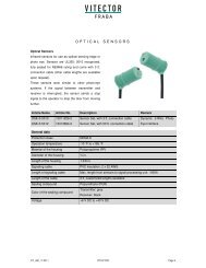
Optical Sensors<br />
Infrared sensors for use as optical sensing edge or<br />
photo eye. Sensors are UL325: 2010 recognized,<br />
fully sealed for NEMA6 rating and come with 3 ft.<br />
connection cable (other cable lengths are available<br />
upon request).<br />
These sensors work similar to other photo-eye<br />
systems. If the signal between transmitter and<br />
receiver is interrupted, the sensor sends a stop<br />
signal to the operator to stop the door from moving<br />
further.<br />
O P T I C A L S E N S O R S<br />
Article Name Article No. Description Remark<br />
OSE-S 5010 10011256-2 Sensor Set, with 3 ft. connection cable Dynamic 2-Wire Photo-<br />
OSE-S 5012 10013694-2 Sensor Set, with 50 ft. connection cable<br />
General data<br />
Protection class NEMA 6<br />
Operation temperature -10 °F to +165 °F<br />
Material of the housing Polypropylene (PP)<br />
Diameter of the housing ¾ in.<br />
Length of the housing 1 3/8 in.<br />
Signaling cable PVC Insulation, 2 x 22 AWG<br />
Length of signaling cable Max. length from sensors to signal processing unit: ~650ft<br />
Length of the cable 3 ft, customized lengths available<br />
Sealing compound Polyurethane (PUR)<br />
Color of the sealing compound<br />
Transmitter: grey<br />
Receiver: black<br />
Voltage +6 V DC to +40 V DC<br />
Eye Interface<br />
VIT_AM_11/2011 VITECTOR Page 4
Application and Drawings<br />
These sensors are used for both the OPTOEYE<br />
photo eye and OPTOEDGE sensing edge system.<br />
The sensors are simply placed within the photo eye<br />
brackets (OPE-S) or the rubber profile (OSE-P) for<br />
each system respectively.<br />
Operator Connection<br />
For either the OPTOEYE or OPTOEDGE systems<br />
the transmitter and receiver are connected in the<br />
same way as shown.<br />
Logic Board Operators<br />
Photoeye input<br />
of operator<br />
O P T I C A L S E N S O R S<br />
Sensing Edge Photo Eye<br />
Relay Style/ Hard-Wired Operators<br />
NO relay input<br />
of operator<br />
OSE-C 1003<br />
VIT_AM_11/2011 VITECTOR Page 5
Photo-Eye Bracket<br />
O P T O E Y E - P H O T O - E Y E B R A C K E T S<br />
Flexible photo eye brackets to be used with<br />
VITECTOR Optical Sensors as OPTOEYE<br />
commercial photo eye. OPTOEYE has a range of<br />
45 ft., is UL325:2010 recognized and has been<br />
NEMA4X rated by UL. Brackets come in a set with<br />
fasteners for installation.<br />
Article Name Article No. Description Remark<br />
OPE-S 1000 10009052-2<br />
General Data<br />
OPTOEYE adapters pair for<br />
Photo Eye use<br />
Protection class NEMA 4X (comparable to IP65)<br />
Operation temperature -10 °F to +165 °F<br />
Material of the housing Thermoplastic Elastomer (TPE)<br />
Range / Working Distance Up to 45ft<br />
Drawings<br />
Plastic lens used on Receiver<br />
VIT_AM_11/2011 VITECTOR Page 6
Connection Set<br />
O P T O E Y E - C O N N E C T I O N S E T<br />
The Connection Set for the OPTOEYE includes a<br />
short section of flexible conduit and a junction box,<br />
allowing for installation in applications that require<br />
all wiring to be done in conduit. The Junction Box<br />
includes a round knock-out to jump into standard ½”<br />
conduit.<br />
Article Name Article No. Components<br />
CS 2400 10010211-2 2 pcs. Junction Boxes // 2 pcs flexible Conduit<br />
Description (Components)<br />
Article Name Description Remark<br />
Flexible Conduit, 3/16 “<br />
3 ft. length, stainless<br />
steel<br />
For protection of wiring in commercial/ industrial<br />
applications<br />
JB 2817 Junction Box Junction box with wire-nuts<br />
VIT_AM_11/2011 VITECTOR Page 7
Rubber Profile<br />
O P T O E D G E - R U B B E R P R O F I L E<br />
Rubber extrusion to be used with Optical Sensors<br />
as OPTOEDGE sensing edge. OPTOEDGE can be<br />
used up to a length of 30 ft, is UL325:2010<br />
recognized and can easily be assembled on-site.<br />
The rubber profiles provide a chamber for the<br />
infrared light and should the profile be deformed,<br />
the signal is interrupted and the hazardous<br />
movement is stopped.<br />
Article Name Article No. Material Dimensions<br />
(Width / Height)<br />
Remark<br />
OSE-P 25 60 01 10008995-2 EPDM ~1¾ / ~2½ in. Rolling Door Profile<br />
OSE-P 40 40 00 10005677-2 EPDM 1 to 2 in. / 1½ to 2 in. Sectional Door Profile<br />
General Data<br />
Material Marking EPDM<br />
Chemical marking Ethylene-Propylene-Terpolymer<br />
Rebound elasticity at 20 °C Good (> 25 %)<br />
Resistance against permanent deformation Good<br />
Elongation at tear > 400 %<br />
General weatherproof-ness Excellent<br />
Ozone resistance Excellent (degree 0)<br />
Oil resistance Poor<br />
Fuel resistance Poor<br />
Chemical solvent-resistance Poor<br />
General resistance against acids Good<br />
Salt water resistance Stable<br />
Light-resistance Good<br />
Temperature-resistance<br />
Short term approx.<br />
Long-term approx..<br />
Recommendation for Storage<br />
-60 °F to +250 °F<br />
-40 °F to +210 °F<br />
Due to the fact that the device is dependent on reacting to deformations in the profile, the profiles must be<br />
stored and shipped without kinks and sharp bends. A pollution of the hollow chamber during the storage<br />
should to be prevented by a suitable package. A longer storage (> 6 months) in rolls should be avoided.<br />
VIT_AM_11/2011 VITECTOR Page 8
OSE-P 40 40 00<br />
General Data<br />
O P T O E D G E - R U B B E R P R O F I L E<br />
Art. Name OSE-P 40 40 00<br />
Art. Number 10005677-2<br />
Application Sectional Doors<br />
Mounting Situation Double C-Channel<br />
Range / Working Distance Up to 30ft<br />
Mounted Height ~1½ to ~2 in.<br />
Mounted Width ~1 to ~2 in.<br />
OSE-P 25 60 01<br />
General Data<br />
Art. Name OSE-P 25 60 01<br />
Art. Number 10008995-2<br />
Application Rolling Doors<br />
Mounting Situation Double L Bracket<br />
Range / Working Distance Up to 30ft<br />
Mounted Height 2 ¾’’<br />
Mounted Width 1’’<br />
VIT_AM_11/2011 VITECTOR Page 9
Retainer<br />
A C C E S S O R I E S - R E T A I N E R<br />
Most commercial doors are equipped with the<br />
proper retainer in order to install an OPTOEDGE<br />
rubber profile. For retro-fitting or door sections<br />
without the right retainer, VITECTOR offers special<br />
retainers for installation of OPTOEDGE sensing<br />
edges.<br />
General Data<br />
Material Aluminum or PVC<br />
Usage Sectional Doors<br />
Aluminum Profile Retainers<br />
Article Name Article No. Door Thickness (b) Retainer Height (a)<br />
ALU-3538 10005850-2 1 3/8 in. 1½ in.<br />
ALU-4545 10009938-2 1¾ in. 1¾ in.<br />
ALU-5151 10009939-2 2 in. 2 in.<br />
PVC Profile Retainers<br />
Article Name Article No. Door Thickness (b) Retainer Height (a)<br />
PVC-3538 10013006 -2 1 3/8 in. 1½ in.<br />
PVC-4545 10013007-2 1¾ in. 1¾ in.<br />
PVC-5151 10013008-2 2 in. 2 in.<br />
VIT_AM_11/2011 VITECTOR Page 10<br />
a<br />
b
Connection Set<br />
A C C E S S O R I E S - C O N N E C T I O N S E T<br />
Connection sets contain everything required to<br />
electrically connect the OPTOEDGE to an<br />
operator. They include a junction box, coil cord,<br />
an offset bracket, and the respective bumper for<br />
that particular door.<br />
Each set contains all components listed below; except CS 2200 comes with the bumper OSE-B 4532 used<br />
with sectional doors and CS 2001 comes with the bumper OSE-B 3035 used on rolling doors.<br />
Article Name Article No. Door Type<br />
CS 2200 10009960-2 Sectional*<br />
CS 2201 10009961-2 Rolling**<br />
Description (Components)<br />
Article Name Article No. Description Remark<br />
OSE-A 5001 10008813-2 Adapter Sleeve For installation in OSE-P rubber profiles<br />
JB 2814 10009128-2 Junction Box Small junction box with wire-nuts<br />
JB 2817 10010069-2 Junction Box Medium junction box with wire-nuts<br />
SC 2360 10009954-2 Coil Cord For all Sensing Edges<br />
AC 2001 10009209-2 Offset Bracket Optional, depending on door height<br />
CS 5030 10010097-2 Connection Cable Cable for connecting junction boxes<br />
*OSE-B 4532 10010086-2` Bumper Modular Bumper for ends of sectional door edge<br />
**OSE-B 3035 10010086-2 Rolling Door Bumper Bumper for ends of rolling door edge<br />
VIT_AM_11/2011 VITECTOR Page 11
Bumpers<br />
A C C E S S O R I E S - B U M P E R S<br />
Bumpers are necessary on both ends of the<br />
sensing edge as they protect the Optical Sensors<br />
from damage from hitting the ground or object.<br />
Article Name Article No. Remark<br />
OSE-B 3035 10010086-2 For Rolling Door Profiles<br />
OSE-B 4632 10009942 -2 For Sectional Door Profiles (Modular Type)<br />
Drawings<br />
Rolling Doors OSE-B 3035<br />
Sectional Doors OSE-B 4632<br />
VIT_AM_11/2011 VITECTOR Page 12
Adapter Sleeve<br />
A C C E S S O R I E S - A D A P T E R S L E E V E<br />
Adapter sleeves allow for the Optical Sensors to fit<br />
tightly into the OSE-P rubber profile / weather-seal<br />
They are placed fully over the sensor before<br />
installation in the edge.<br />
Article Name Article No. Remark<br />
OSE-A 5001 10008813 -2 Adapter Sleeve for use with Optical Sensors<br />
Dimensions<br />
VIT_AM_11/2011 VITECTOR Page 13
Junction Box<br />
A C C E S S O R I E S - M E D I U M J U N C T I O N B O X<br />
The JB 2XXX junction boxes are fitted with two<br />
open cable entries (M16) in the lid and in the box.<br />
One M16 cable gland with bending protection<br />
sleeve is included and one M16 gland with a two-<br />
holed grommet is installed. A knockout cable entry<br />
in the wall of the box allows for an additional M16 or<br />
M20 cable entry. A pair of wire nuts for the OSE<br />
connection comes with the box; mounting screws<br />
are included.<br />
Article Name Article No. Remark<br />
JB 2814 10009128-2 Junction Box<br />
General Data<br />
Material ABS, light grey (RAL 7035)<br />
Protection Class NEMA 4<br />
Dimensions (without cable entries) Length Width Height<br />
JB 2814 3½ in. 2 in. 1 5/8 in.<br />
Drawing<br />
VIT_AM_11/2011 VITECTOR Page 14
Coil Cord<br />
A C C E S S O R I E S - C O I L C O R D<br />
VITECTOR coil cords are used for connecting<br />
sensing devices to the door operator. These coil<br />
cords are made of durable TPU material, which<br />
makes them highly resistant against shearing or<br />
ripping.<br />
Article Name Article No. Conductors<br />
General Data<br />
Cable structure Lif 11 Y 11 Y, Copper fine wired, stranded<br />
Wire insulation TPU<br />
Jacket insulation TPU, black<br />
Cable ends open<br />
Temperature Range -40 °F to +190 °F<br />
Extendable<br />
Length<br />
Dimensions<br />
d A B C<br />
SC 2360 10009954-2 2 x AWG24 13 ft. ¼ in. 6 in. 3 ft. 5 ft.<br />
VIT_AM_09/11 VITECTOR Page 15
Offset Bracket<br />
A C C E S S O R I E S - O F F S E T B R A C K E T<br />
The offset bracket is made from galvanized steel. It<br />
is used to fix the coil cord to the guide rail or wall at<br />
half the total height of the door to help prevent coil<br />
cord damage. The offset bracket is supplied with an<br />
M16 bend protection to extend the lifetime of the<br />
coil cord.<br />
Article Name Article No. Remark<br />
AC 2001 10009209-2 Offset Bracket for Sectional Doors<br />
Drawings<br />
VIT_AM_11/2011 VITECTOR Page 16
Converter Box<br />
A C C E S S O R I E S – C O N V E R T E R B O X<br />
The converter box is used to connect up to two<br />
sensing devices on a relay style operator.<br />
The converter box is able to convert the dynamic<br />
signal of the optical sensors to a NO dry contact<br />
relay output that can be connected to a relay<br />
style operator.<br />
Article Name Article No. Remark<br />
OSE-C 1003 10005699-2 Used for relay style operators (no logic board)<br />
Controller OSE – C 1003<br />
General Data<br />
Black 12 / 24 V AC Input<br />
Gray<br />
Normally Open Dry Contact<br />
Relay Output<br />
Red Primary OSE Input<br />
Orange Secondary OSE Input (optional)<br />
Yellow Close Door Button (optional)<br />
Push Button Sensing<br />
When used on some brands of operators, the<br />
OSE-C 1003 can monitor the close push button<br />
and allow a constant contact to close if the<br />
controller detects a fault with one of the external<br />
sensing edges. Typically this feature will not work<br />
with instant reversing or 3-phase motors.<br />
Connection Diagram<br />
VIT_AM_11/2011 VITECTOR Page 17
Reset Procedure<br />
A C C E S S O R I E S – C O N V E R T E R B O X<br />
Once the OSE-C 1003 detects a sensing edge, it<br />
saves this status to permanent memory. When<br />
power is removed and reapplied, the OSE-C<br />
1003 expects the device to be present. If not, it<br />
will activate the reversing signal. To reset the<br />
controller first disconnect power. Then<br />
disconnect any sensing edge and one of the gray<br />
wires from the operator. Remove the back of the<br />
OSE-C 1003, locate the shunt jumper on the<br />
printed circuit board and place it in the reset<br />
position. Apply power to the controller for 2<br />
seconds with the shunt jumper in the reset<br />
position. Disconnect power from the unit and<br />
move the shunt jumper back to the original<br />
position. Reconnect the gray wire (removed<br />
above) to the operator. Finally reconnect the<br />
sensing edge(s) and return power to retest and<br />
resume operation.<br />
VIT_AM_11/2011 VITECTOR Page 18
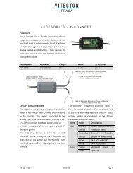
Y-Connect<br />
A C C E S O R I E S - Y - C O N N E C T<br />
The Y-Connect allows for the connection of two<br />
independent entrapment protection devices into the<br />
monitored input of a door operator board. It will give<br />
an obstruction signal to the operator if either of the<br />
devices senses an obstruction. If both devices do<br />
not sense an obstruction the operator receives a<br />
valid dynamic signal.<br />
Article Name Article No. Length Width Thickness<br />
YC 1000 10013081-2 3 in 1 5/8 in. ½ in<br />
Circuitry and Connections<br />
The signal of the primary entrapment protection<br />
device is fed through the Y-Connect and monitored<br />
by the operator. The sensor connected to the<br />
primary input is the monitored device and has to be:<br />
A UL325 recognized monitored sensing edge or<br />
A UL325 recognized photo-eye system placed 6”<br />
above the ground.<br />
The Secondary Device is connected to and<br />
monitored by the circuitry of the Y-Connect. An<br />
obstruction of the sensor will interrupt the main<br />
monitored dynamic 2-wire signal going to the door<br />
controller.<br />
The secondary entrapment protection device is<br />
there for added protection. For compliance with<br />
UL325 it is extremely important that the UL325<br />
certified sensor is connected as the Primary<br />
Entrapment Protection Device.<br />
Signal Cable Description<br />
Input Primary<br />
Device<br />
Secondary<br />
Device<br />
UL325 listed Entrapment<br />
Protection Device<br />
Second Protection<br />
Sensor for added safety<br />
Brown 24 V AC/ +24 V DC<br />
White 24 V AC/ Ground<br />
Output Yellow Monitored Input of<br />
Green<br />
Operator<br />
VIT_AM_11/2011 VITECTOR Page 19
General Data<br />
A C C E S O R I E S - Y - C O N N E C T<br />
Protection Class NEMA4<br />
Housing Material ABS/PA6 GF30/TPE<br />
Operation Temperature -10 °F to 170°F<br />
Supply Voltage 24 V AC/DC<br />
Power Consumption < 15 mA<br />
Response Time 33 ms obstruction time with Secondary<br />
LED Characteristics<br />
LED Status Description<br />
YELLOW ON Power ON<br />
GREEN OFF No valid dynamic signal / Obstruction<br />
GREEN ON Valid dynamic signal / No obstruction<br />
Diagrams and Drawings<br />
VIT_AM_11/2011 VITECTOR Page 20
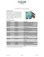
Pneumatic Switches<br />
Pneumatic Switches are sensing devices used to<br />
detect obstruction of a moving edge. A signal is<br />
received when a deformation generates a pressure<br />
wave which is detected by the pneumatic switch.<br />
There are three types of contacts; normally open<br />
contact (S), normally closed contact (O), and<br />
change over contact (W).<br />
Pneumatic switches - DW<br />
P N E U M A T I C S W I T C H E S<br />
Article Name Article No. Description<br />
DW 2S-100 10005733-2 round connector plugs 90°, NOC<br />
DW 2O-100 10005859-2 round connector plugs 90°, NCC<br />
DW 3S-100 10005652-2 screw type connectors, NOC<br />
DW 3S-200 10005688-2 screw type connectors, NOC, in medium-<br />
sized enclosure<br />
DW 3S-300 10008797-2 screw type connectors, NOC, in big enclosure<br />
DW 3O-100 10005713-2 screw type connectors, NCC<br />
DW 3O-200 10005687-2 screw type connectors, NCC, in medium-<br />
sized enclosure<br />
DW 3O-300 10007432-2 screw type connectors, NCC, in big enclosure<br />
DW 3O-306 10007379-2 NCC on PCB, large housing, 2 x stop circuit<br />
DW 3W-420 10005797-2 screw type connectors, NOC/NCC<br />
changeover contact, galvanized steel<br />
mounting flange<br />
DW 3W-220 10005795-2 screw type connectors, NOC/NCC<br />
changeover contact, in medium-sized<br />
enclosure<br />
DW 5S-100 10005856-2 6,3 mm flat connector type, NOC<br />
DW 5O-100 10005857-2 6,3 mm flat connector type, NCC<br />
mounting kit * 10005918-2 small mounting angle and 2 pieces M3x25<br />
* = this part is equipped as standard by the DW-3W 420<br />
screws<br />
VIT_AM_11/2011 VITECTOR Page 21
General data<br />
P N E U M A T I C S W I T C H E S<br />
Diaphragm material 0.01” EPDM (-20 °F to +300 °F)<br />
Weight 1/8 lbs<br />
Dimensions 2 1/8 in x 1 ¾ in x 1 ¼ in<br />
Contact loads 220 V, 0.5 A<br />
Number of operations max. 10/sec<br />
Response sensitivity 0.2 to 50 mbar<br />
Standard setting 3 mbar<br />
Mechanical resistance 200 mbar<br />
Ventilation screw Factory preset open, tighter setting available on request<br />
Types of Housing grey, type 200 or 300<br />
Mounting Mounting plate with 4mm holes; Various Mounting Angles;<br />
Mount to DIN Rail<br />
Connectors ¼” flat connectors<br />
Drawings<br />
VIT_AM_11/2011 VITECTOR Page 22
Optional Housing (NEMA 4)<br />
Housing Type 200<br />
P N E U M A T I C S W I T C H E S<br />
Housing Type 300<br />
VIT_AM_11/2011 VITECTOR Page 23
P N E U M A T I C S W I T C H E S - R A D I O S W I T C H<br />
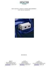
Wireless Pneumatic Switch<br />
RADIOSWITCH made by VITECTOR is a<br />
pneumatic switch that sends a radio signal to the<br />
receiving unit upon activation. The small radio<br />
transmitter unit and the pneumatic switch are<br />
packaged within the DW 3S-200 case while the<br />
receiver is built into a NEMA4 case. For easy<br />
connection to a control unit it is equipped with a<br />
NCC (normally closed contact) or NOC (normally<br />
open contact) relay.<br />
Article Name Article No. Remark<br />
DW TR-200 10012830-2 Transmitter Unit with Airwave Switch<br />
RSW-R 1502, 433MHZ NCC 10012813-2 Receiver Unit, NCC Relay Output<br />
RSW-R 1502, 433MHZ NOC 10013858-2 Receiver Unit, NOC Relay Output<br />
Diagrams<br />
Transmitter Receiver<br />
Transparent cover<br />
Replacable battery<br />
Green status LED<br />
Pneumatic connection<br />
Programming button<br />
Red status LED<br />
grey-transparent plastic cover<br />
Wiring:<br />
Brown: +24 V<br />
White: 0V<br />
Green/Yellow: relay output<br />
Antenna<br />
VIT_AM_11/2011 VITECTOR Page 24
P N E U M A T I C S W I T C H E S - R A D I O S W I T C H<br />
Transmitter General Data<br />
Frequency band 433 MHz, modulated frequency<br />
Coding Fixed codes, 65,000 different codes available<br />
Protection class NEMA 4<br />
Temperature range -5 °F to +140 °F<br />
Transmitting range Up to 330 ft<br />
Battery Lithium CR2032, 3,0 V, 220 mAh, replaceable<br />
Battery Lifetime up to 75,000 activations, max. 4 years<br />
Status LED Green<br />
Receiver General Data<br />
Receiving channels 1<br />
Response time Minimum 35 ms (without radio interference)<br />
Protection class NEMA 4<br />
Case material ABS transparent grey, PA6 GF30, TPE<br />
Dimensions 2.95 x 1.57 x 0.51 inch without wiring<br />
Connection 4-core connection wire LIYY 4x0,14²<br />
Current drawn max. 30 mA<br />
Signal/ Relay output<br />
Status OK<br />
Status Crash/ Error<br />
Length 3.28 ft<br />
Cable head 1.97 inch dismantled, twisted and tinned<br />
isolation stripped 0.2 inch<br />
Brown: +24V( AC/DC), White: 0V, Green/Yellow: relay output<br />
NCC (normally closed)<br />
Closed<br />
Open<br />
Status LED red<br />
NOC (normally open)<br />
Open<br />
Closed<br />
VIT_AM_11/2011 VITECTOR Page 25
P N E U M A T I C S W I T C H E S - R A D I O S W I T C H<br />
Factory Default Setting<br />
Transmitter with fixed code, receiver not<br />
programmed, upon switching on the receiver the<br />
status LED is permanently red, receiver has to be<br />
programmed before first use. When receiving a<br />
signal from any compatible transmitter, the status<br />
LED flashes briefly before going back to red<br />
permanently.<br />
Relay opened – no door/ gate function<br />
Programming<br />
Press programming button for 3 seconds, LED<br />
flashes slowly. Now activate the DW switch within 5<br />
minutes. Upon receiving the DW signal, the receiver<br />
LED rapidly flashes 8 times while the code is being<br />
saved. After that, the LED turns off.<br />
Normal Operation<br />
Upon activation of its pneumatic switch, the<br />
transmitter generates the code signal and sends it<br />
to the receiver 20 times. The receiver’s minimum<br />
response time is approx. 35 ms. if a signal cannot<br />
be transmitted due to interference problems, the<br />
remaining attempts provide a certain level of<br />
reliability. After approx. 700 ms transmission is<br />
terminated and the transmitter’s LED flashes once.<br />
Upon receiving the transmitted signal, the<br />
receiver’s LED lights up for 4 seconds.<br />
Simultaneously the clearance signal (relay output)<br />
is being activated for 4 seconds<br />
Delete Programming or Re-Program<br />
Pressing the programming button for 3 seconds<br />
deletes the currently saved code from memory and<br />
the receiver can be re-programmed as described<br />
above.<br />
Low Battery<br />
If the battery voltage drops below a certain value,<br />
the transmitter’s LED flashes twice (instead of<br />
once) and battery replacement should be<br />
considered. Additionally, if the battery is not<br />
replaced the receiver’s LED will flash from now on.If<br />
the voltage drops below a critical level, the receiver<br />
LED will flash slower indicating that the relay gate<br />
is no longer being set.<br />
VIT_AM_11/2011 VITECTOR Page 26
P N E U M A T I C S W I T C H E S - R A D I O S W I T C H<br />
Status LED Conditions<br />
Transmitter LED<br />
Activity LED Description<br />
Off<br />
Flashes once<br />
Flashes twice<br />
Flashes 3 x<br />
Receiver LED<br />
idle<br />
Activity LED Description<br />
Off<br />
Flashing steadily<br />
Rapidly flashes 8 x<br />
Flashes once<br />
Flashes permanently<br />
Blinking permanently<br />
activation signal is being transmitted. System OK<br />
Activation signal is being transmitted with reduced power,<br />
battery is low. Replace battery!<br />
Activation signal is being transmitted with heavily reduced<br />
power, better is nearly empty, no relay activation<br />
Replace battery immediately!<br />
idle<br />
Ready for being programmed<br />
Transmitter code is being saved<br />
Relay gate is being set. System OK<br />
Relay gate is being set. Transmitter battery low, consider<br />
replacing<br />
Relay gate is not being set. Transmitter battery very low,<br />
Replace immediately<br />
VIT_AM_11/2011 VITECTOR Page 27
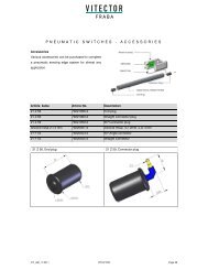
Accessories<br />
P N E U M A T I C S W I T C H E S - A C C E S S O R I E S<br />
Various accessories can be purchased to complete<br />
a pneumatic sensing edge system for almost any<br />
application.<br />
Article Name Article No. Description<br />
21 Z 56 79221956-2 End plug<br />
21 Z 60 79221960-2 Straight Connector plug<br />
21 Z 59 79221959-2 90° Connector plug<br />
Silicone hose 2 x 5 mm 79220001-2 Silicone Hose, i.D. 2mm, o.D. 5mm<br />
21 F 53 79220453-2 90° Angle connector<br />
21 F 55 79220455-2 Straight Connector<br />
21 Z 56, End plug 21 Z 59, Connector plug<br />
VIT_AM_11/2011 VITECTOR Page 28
P N E U M A T I C S W I T C H E S - A C C E S S O R I E S<br />
21 Z 60, Connector plug 21 F 55, Connectors ∅ 2 x 4 mm<br />
21 F 53, Angle-connector ∅ 2 x 4 mm<br />
VIT_AM_11/2011 VITECTOR Page 29
COMPANY PARTNERS<br />
Cologne, Germany<br />
Hamilton/ NJ, U.S.A.<br />
Singapore<br />
Slubice, Poland<br />
VITECTOR - FRABA Inc.<br />
1800 East State St., Ste. 148, Hamilton, NJ 08609<br />
T +1 609 750 8705<br />
F +1 609 750 8703<br />
info@vitector.com<br />
GDI<br />
Gates and Doors Inc.