5 Graphical Mixed Reality User Interface - OPUS - Universität ...
5 Graphical Mixed Reality User Interface - OPUS - Universität ...
5 Graphical Mixed Reality User Interface - OPUS - Universität ...

You also want an ePaper? Increase the reach of your titles
YUMPU automatically turns print PDFs into web optimized ePapers that Google loves.
Band 5<br />
Institut für Informatik<br />
Lehrstuhl für Robotik und Telematik<br />
Prof. Dr. K. Schilling<br />
Würzburger Forschungsberichte<br />
in Robotik und Telematik<br />
Uni Wuerzburg Research Notes<br />
in Robotics and Telematics<br />
Markus Sauer<br />
<strong>Mixed</strong>-<strong>Reality</strong> for<br />
Enhanced Robot<br />
Teleoperation
Lehrstuhl Informatik VII<br />
Robotik und Telematik<br />
Am Hubland<br />
D-97074 Wuerzburg<br />
Tel.: +49 (0) 931 - 31 - 86678<br />
Fax: +49 (0) 931 - 31 - 86679<br />
schi@informatik.uni-wuerzburg.de<br />
http://www7.informatik.uni-wuerzburg.de<br />
Dieses Dokument wird bereitgestellt<br />
durch den Online-Publikationsserver der<br />
<strong>Universität</strong> Würzburg.<br />
<strong>Universität</strong>sbibliothek Würzburg<br />
Am Hubland<br />
D-97074 Würzburg<br />
Tel.: +49 (0) 931 - 31 - 85917<br />
Fax: +49 (0) 931 - 31 - 85970<br />
opus@bibliothek.uni-wuerzburg.de<br />
http://www.opus-bayern.de/uniwuerzburg/<br />
ISSN (Internet): 1868-7474<br />
ISSN (Print): 1868-7466<br />
eISBN: 978-3-923959-67-9<br />
Die Schriftenreihe<br />
wird vom Lehrstuhl für Informatik VII: Robotik und<br />
Telematik der <strong>Universität</strong> Würzburg herausgegeben und<br />
präsentiert innovative Forschung aus den Bereichen der<br />
Robotik und der Telematik.<br />
Die Kombination fortgeschrittener Informationsverarbeitungsmethoden<br />
mit Verfahren der Regelungstechnik<br />
eröffnet hier interessante Forschungs- und Anwendungsperspektiven.<br />
Es werden dabei folgende interdisziplinäre<br />
Aufgabenschwerpunkte bearbeitet:<br />
Ÿ Robotik und Mechatronik: Kombination von Informatik,<br />
Elektronik, Mechanik, Sensorik, Regelungs- und<br />
Steuerungstechnik, um Roboter adaptiv und flexibel<br />
ihrer Arbeitsumgebung anzupassen.<br />
Ÿ Telematik: Integration von Telekommunikation, Informatik<br />
und Steuerungstechnik, um Dienstleistungen<br />
an entfernten Standorten zu erbringen.<br />
Anwendungsschwerpunkte sind u.a. mobile Roboter, Tele-<br />
Robotik, Raumfahrtsysteme und Medizin-Robotik.<br />
Zitation dieser Publikation<br />
SAUER, M. (2010). <strong>Mixed</strong>-reality for enhanced robot<br />
teleoperation. Schriftenreihe Würzburger<br />
Forschungsberichte in Robotik und Telematik, Band 5.<br />
Würzburg: <strong>Universität</strong> Würzburg.
<strong>Mixed</strong>-<strong>Reality</strong> for Enhanced Robot<br />
Teleoperation<br />
Dissertation zur Erlangung des<br />
naturwissenschaftlichen Doktorgrades<br />
der Bayerischen Julius–Maximilians–<strong>Universität</strong> Würzburg<br />
vorgelegt von<br />
Markus Sauer<br />
aus<br />
Würzburg<br />
Würzburg 2010
Eingereicht am: 22.07.2010<br />
bei der Fakultät für Mathematik und Informatik<br />
1. Gutachter: Prof. Dr. Klaus Schilling<br />
2. Gutachter: Prof. Dr. Aarne Halme<br />
Tag der mündlichen Prüfung: 01.02.2011
Danksagung<br />
Die vorliegende Dissertation wäre nicht möglich gewesen ohne die tatkräftige<br />
Unterstützung von vielen Menschen, denen ich im Folgenden noch einmal herzlich<br />
danken möchte.<br />
Zuerst bedanke ich mich bei meinem Doktorvater Prof. Dr. Klaus Schilling für<br />
die Möglichkeit eine Promotion unter seiner Betreuung durchzuführen, aber auch<br />
für die vielen spannenden Dinge, die ich die letzten Jahre erleben durfte, und<br />
die Erfahrungen, die ich dabei sammeln konnte. Er ermöglichte mir eine berufliche<br />
und persönliche Weiterentwicklung, die sonst bei einer Promotion nicht<br />
selbstverständlich ist. Prof. Dr. Aarne Halme einen herzlichen Dank für seine<br />
unkomplizierte Art und die zügige Erstellung des Zweitgutachtens. Ein weiterer<br />
Dank gilt meinen beiden Prüfern Prof. Dr. Phuoc Tran-Gia und Prof. Dr. Jürgen<br />
Albert. Beide habe ich schon während meines Studiums, aber auch jetzt während<br />
meiner Promotionszeit sowohl menschlich als auch fachlich sehr schätzen gelernt.<br />
Durch die Arbeit während der Promotion am Lehrstuhl für Robotik und<br />
Telematik der <strong>Universität</strong> Würzburg und dem Zentrum für Telematik hatte ich<br />
die Gelegenheit mit einem außergewöhnlichen Team zusammenzuarbeiten, was<br />
sich auch in privaten gemeinsamen Unternehmungen außerhalb der Arbeit widerspiegelte.<br />
Danke hierfür im Besonderen an Maximilian Drentschew, Daniel<br />
Eck, Matthias Görs, Christian Herrmann, Dr. Martin Hess, Robin Heß, Dr. Peter<br />
Hokayem, Markus Krauß, Florian Leutert, Dr. Lei Ma, Marco Schmidt,<br />
Rajesh Shankar Priya, Prof. Dr. Dušan Stipanović und Lothar Stolz, sowie<br />
Heidi Frankenberger, Ulrike Walter, Eberhard von Deuster, Dieter Ziegler, Edith<br />
Reuter und Annette Zillenbiller. Bei zwei Kollegen und Freunden möchte ich<br />
mich nochmal separat besonders bedanken - Dr. Frauke Driewer und Dr. Florian<br />
Zeiger. Mit beiden habe ich in meiner Promotionszeit am engsten zusammengearbeitet<br />
und fachliche aber auch persönliche Diskussionen geführt, was<br />
ich immer sehr zu schätzen wusste. Danke auch nochmal an Dr. Florian Zeiger,<br />
i
Danksagung<br />
dass er in unserem gemeinsamen Endspurt der Doktorarbeit in den letzten beiden<br />
Jahren egal unter welchen Umständen immer wieder den nötigen Zug aufgebaut<br />
hat und, dass er immer als Freund zur Verfügung stand. Herzlichen Dank<br />
an alle Kollegen vom Lehrstuhl III - unserem zweiten Zuhause. Die unzähligen<br />
Lehrstuhl III - Aktivitäten, bei denen wir dabei waren, haben eine bleibende<br />
Erinnerung hinterlassen, die ich nicht missen möchte. Hier nochmal einen ganz<br />
besonderen Dank an Dr. Rastin Pries und Dr. Robert Henjes für die unzähligen<br />
gemeinsamen Abende und die tolle Zeit, die wir hoffentlich in Zukunft mit<br />
allen aufrecht erhalten, bzw. immer wieder regelmäßig aufleben lassen werden.<br />
Danke auch an meinen Kommilitonen Marco Schörger für die über zehnjährige<br />
Freundschaft und seine immer positive Grundeinstellung und Art. In den letzten<br />
Jahren durfte ich im Rahmen dieser Arbeit auch mit einer Vielzahl von Studenten<br />
zusammenarbeiten. Stellvertretend für alle diese Studenten möchte ich mich insbesondere<br />
bei meinen Diplomanden Stephan Toth, Matthias Wiedemann, Manuel<br />
Göllnitz, Koami Edem Missoh, Hossein Shahrabi Farahani, Lakshminarasimhan<br />
Srinivasan und Thomas Peretzki bedanken.<br />
Vielen Dank an meine Eltern Brigitte und Klaus und meinen Brüdern Florian<br />
und Benedikt für die uneingeschränkte Unterstützung und den Rückhalt in all den<br />
Jahren. Das Bewusstsein über diese Unterstützung und diesen Rückhalt gab mir<br />
die Sicherheit, die in vielen Situation für diese Arbeit wichtig war. Zu guter Letzt<br />
möchte ich mich bei dem wichtigsten Menschen in meinem Leben bedanken -<br />
meiner Freundin Carolin Lamprecht. In all den Jahren, die wir bisher gemeinsam<br />
gegangen sind, war sie immer meine Kraft und meine Stärke. Wann immer ich<br />
jemand brauchte, war sie für mich da, egal zu welcher Zeit, oder an welchem<br />
Ort. Wann immer ich Zweifel hatte, hat sie an mich geglaubt und mich wieder<br />
aufgebaut. Danke für alles!<br />
ii
Contents<br />
1 Introduction 1<br />
1.1 Exemplary Application: Robots in Urban Search and Rescue . . . 2<br />
1.2 Outline . . . . . . . . . . . . . . . . . . . . . . . . . . . . . . . 4<br />
1.3 Innovations . . . . . . . . . . . . . . . . . . . . . . . . . . . . 5<br />
2 Human in the Loop 9<br />
2.1 Human-Robot Interaction (HRI) . . . . . . . . . . . . . . . . . . 9<br />
2.1.1 Characteristics of HRI . . . . . . . . . . . . . . . . . . . 10<br />
2.1.2 Interaction Roles . . . . . . . . . . . . . . . . . . . . . 12<br />
2.2 Teleoperation . . . . . . . . . . . . . . . . . . . . . . . . . . . 14<br />
2.2.1 Interaction between Humans and Autonomy . . . . . . . 16<br />
2.2.2 <strong>User</strong> <strong>Interface</strong>s . . . . . . . . . . . . . . . . . . . . . . 17<br />
2.2.3 Studies and <strong>User</strong> <strong>Interface</strong> Guidelines . . . . . . . . . . 19<br />
2.3 Human Factors . . . . . . . . . . . . . . . . . . . . . . . . . . . 22<br />
2.3.1 Telepresence . . . . . . . . . . . . . . . . . . . . . . . . 22<br />
2.3.2 Situation Awareness . . . . . . . . . . . . . . . . . . . . 23<br />
2.3.3 Common Ground . . . . . . . . . . . . . . . . . . . . . 24<br />
2.3.4 Workload . . . . . . . . . . . . . . . . . . . . . . . . . 26<br />
2.3.5 Spatial Cognition . . . . . . . . . . . . . . . . . . . . . 26<br />
2.4 Evaluation of Human-Robot Interaction . . . . . . . . . . . . . . 29<br />
2.5 Designing the Teleoperation System . . . . . . . . . . . . . . . . 31<br />
2.5.1 Model of the Teleoperation System . . . . . . . . . . . . 31<br />
2.5.2 Design Goals and Demands . . . . . . . . . . . . . . . . 34<br />
3 3D-Perception and Communication Networks for Teleoperation<br />
Systems 39<br />
3.1 Enabling Technologies . . . . . . . . . . . . . . . . . . . . . . . 40<br />
3.1.1 Communication Technologies . . . . . . . . . . . . . . . 40<br />
iii
Contents<br />
3.1.2 Network Parameters and Video Streams . . . . . . . . . 45<br />
3.1.3 Three-Dimensional Perception . . . . . . . . . . . . . . 47<br />
3.1.4 3D-Time-of-Flight Cameras . . . . . . . . . . . . . . . . 47<br />
3.1.5 Optical Camera Calibration . . . . . . . . . . . . . . . . 52<br />
3.1.6 Sensor Data Fusion, Localization and Mapping . . . . . . 55<br />
3.2 A Concept for Intelligent Traffic Shaping in Wireless Networks . 56<br />
3.2.1 Scenarios . . . . . . . . . . . . . . . . . . . . . . . . . 57<br />
3.2.2 Concept . . . . . . . . . . . . . . . . . . . . . . . . . . 59<br />
3.2.3 Network Feedback and Adaptive Video Quality . . . . . 60<br />
3.2.4 Experiments and Validation . . . . . . . . . . . . . . . . 64<br />
3.2.5 Summary . . . . . . . . . . . . . . . . . . . . . . . . . 75<br />
3.3 Three-Dimensional Perception with Range Cameras . . . . . . . 76<br />
3.3.1 Calibration . . . . . . . . . . . . . . . . . . . . . . . . 76<br />
3.3.2 Filtering . . . . . . . . . . . . . . . . . . . . . . . . . . 79<br />
3.3.3 Task Specific Optimization of Integration Time . . . . . . 82<br />
3.4 Application: 3D-Map <strong>User</strong> <strong>Interface</strong> Elements based on PMD Data 86<br />
3.4.1 Frame Matching . . . . . . . . . . . . . . . . . . . . . . 87<br />
3.4.2 3D Panoramas . . . . . . . . . . . . . . . . . . . . . . . 87<br />
3.4.3 <strong>User</strong> Studies . . . . . . . . . . . . . . . . . . . . . . . . 92<br />
3.5 Conclusion . . . . . . . . . . . . . . . . . . . . . . . . . . . . . 98<br />
4 Sliding Autonomy through Haptic Guidance 101<br />
iv<br />
4.1 Concept . . . . . . . . . . . . . . . . . . . . . . . . . . . . . . 104<br />
4.1.1 Command Generation . . . . . . . . . . . . . . . . . . . 105<br />
4.1.2 Guidance Forces . . . . . . . . . . . . . . . . . . . . . . 107<br />
4.1.3 Augmented <strong>Reality</strong> <strong>User</strong> <strong>Interface</strong> . . . . . . . . . . . . 114<br />
4.2 <strong>User</strong> Studies . . . . . . . . . . . . . . . . . . . . . . . . . . . . 115<br />
4.2.1 Metrics . . . . . . . . . . . . . . . . . . . . . . . . . . 115<br />
4.2.2 System Setup for Experiments . . . . . . . . . . . . . . 117<br />
4.2.3 Simulation Experiments . . . . . . . . . . . . . . . . . . 118<br />
4.2.4 Real-world Experiments . . . . . . . . . . . . . . . . . . 126<br />
4.2.5 Experiments on Network Delay Tolerance . . . . . . . . 133<br />
4.3 Conclusion . . . . . . . . . . . . . . . . . . . . . . . . . . . . . 136
Contents<br />
5 <strong>Graphical</strong> <strong>Mixed</strong> <strong>Reality</strong> <strong>User</strong> <strong>Interface</strong> 139<br />
5.1 Enabling Technologies . . . . . . . . . . . . . . . . . . . . . . . 140<br />
5.1.1 Three-Dimensional Elements in <strong>User</strong> <strong>Interface</strong>s . . . . . 140<br />
5.1.2 <strong>Mixed</strong> <strong>Reality</strong> . . . . . . . . . . . . . . . . . . . . . . . 142<br />
5.2 Advanced Augmented <strong>Reality</strong> Overlays . . . . . . . . . . . . . . 146<br />
5.2.1 Registration and Tracking . . . . . . . . . . . . . . . . . 146<br />
5.2.2 Modeling Camera Images . . . . . . . . . . . . . . . . . 148<br />
5.2.3 Occlusion Handling . . . . . . . . . . . . . . . . . . . . 157<br />
5.3 <strong>Mixed</strong> <strong>Reality</strong> <strong>User</strong> <strong>Interface</strong> Approach . . . . . . . . . . . . . . 161<br />
5.3.1 Design and Characteristics . . . . . . . . . . . . . . . . 161<br />
5.3.2 Framework for <strong>Mixed</strong> <strong>Reality</strong> <strong>User</strong> <strong>Interface</strong>s . . . . . . 164<br />
5.4 Realization of <strong>User</strong> <strong>Interface</strong>s . . . . . . . . . . . . . . . . . . . 171<br />
5.4.1 Team Coordination <strong>User</strong> <strong>Interface</strong> . . . . . . . . . . . . 172<br />
5.4.2 Augmented <strong>Reality</strong> Operator <strong>User</strong> <strong>Interface</strong> . . . . . . . 175<br />
5.4.3 Generic <strong>Mixed</strong> <strong>Reality</strong> <strong>User</strong> <strong>Interface</strong> . . . . . . . . . . . 179<br />
5.4.4 <strong>User</strong> Studies . . . . . . . . . . . . . . . . . . . . . . . . 184<br />
5.5 Predictive <strong>Mixed</strong> <strong>Reality</strong> Display . . . . . . . . . . . . . . . . . 193<br />
5.5.1 Predictive Concept . . . . . . . . . . . . . . . . . . . . 193<br />
5.5.2 Discussion of Results . . . . . . . . . . . . . . . . . . . 200<br />
5.6 Summary . . . . . . . . . . . . . . . . . . . . . . . . . . . . . 202<br />
6 Conclusions 205<br />
Bibliography and References 211<br />
v
1 Introduction<br />
In the last decades research in the field of robotics has produced impressive advances<br />
and many interesting applications arose, ranging from e.g. industrial manipulators,<br />
search and rescue, up to robots on Mars. Nevertheless, robots have still<br />
not found their place in everyday life, such that today robotics faces the increasing<br />
requirement of a paradigm shift from industrial applications with fixed requirements<br />
and conditions to everyday, dynamic human environments. Robotics research<br />
has made great progress with respect to applications in such environments<br />
with a higher level of autonomy. But still, there are many tasks and applications<br />
where humans acting as coordinators or operators are needed. Reasons for this<br />
need of human support can be for instance safety issues and/or complex, dynamic<br />
real-world scenarios. The most obvious application examples are robots applied<br />
in human-robot teams in search and rescue scenarios or robots utilized in space<br />
missions. These scenarios include very complex tasks due to e.g. unknown or<br />
hazardous environments, danger for human live, or the risk of a complete mission<br />
failure resulting in costs of some million Euros. During most of these complicated<br />
missions the human is an irreplaceable part. The level of human perception<br />
capabilities and interpretation of the situation, as well as the ability to make<br />
decisions on basis of available limited information, past experience and intuition<br />
is currently not reached by artificial systems. Moreover, the human is needed for<br />
certain tasks, such as in search and rescue missions performing rescue activities<br />
or giving medical and psychological support to victims.<br />
In order to take advantage of the superior adaptive and cognitive abilities of<br />
human in such missions it is a must to provide reasonable user interfaces to the<br />
humans fitting to the current task and the interaction role. Autonomous features of<br />
the vehicle, e.g. path-following or obstacle avoidance, relieve the operator from<br />
simple robot control tasks, and should be integrated as assistance functions to the<br />
user interface. Here, a major issue is to enable the human to both, gain and maintain<br />
situation awareness, and common ground. If common ground between the<br />
1
1 Introduction<br />
(semi-)autonomously behaving robots and the human operator is not achieved,<br />
the operator will either neglect this specific robotic system or turn off all the assistance<br />
systems. Thus, the user interface for the human operator plays one of<br />
the most significant roles for the success of any application of robots operating at<br />
remote.<br />
Due to the nowadays available hardware providing graphical calculations, as<br />
well as computing power at reasonable costs mixed reality systems as a novel<br />
way of building effective, intuitive and integrated human-machine interfaces are<br />
increasingly of interest and realizable. <strong>Mixed</strong> reality systems combine real and<br />
computer generated objects correctly aligned in real environments and run interactively<br />
and in real-time. Dependent on the ratio of virtual and real elements the<br />
mixed reality interfaces can be further subdivided into augmented reality and augmented<br />
virtuality interfaces. Realizing this type of interfaces raises a lot of new<br />
technical challenges. However, these mixed reality concepts with the principle of<br />
integrating all necessary information the same spatial context allow for improved<br />
user interfaces in many areas of robotics. Looking at human factors theory, many<br />
of the requirements for teleoperation systems and user interface design, cannot<br />
be meet as perfect with standard methods as it is possible with mixed reality.<br />
This work investigates the application of mixed reality technologies for teleoperation<br />
of robots. Based on careful analysis of human factors theory, literature<br />
research, and own experiments innovative technological concepts and methodologies<br />
are developed which enable to realize enhanced integrated mixed reality<br />
user interfaces in dependency on the current application, task, and corresponding<br />
interaction roles. This covers the overall teleoperation system from perception,<br />
autonomy design, communication, haptic and graphical user interface elements.<br />
1.1 Exemplary Application: Robots in Urban<br />
Search and Rescue<br />
Mobile robots become more and more an attractive tool to accomplish work in<br />
hazardous environments or in areas not accessible for humans. One of the most<br />
attractive application areas is the field of search and rescue, because of the often<br />
unpredictable danger for human life during an accident or a catastrophe. Typical<br />
scenarios where robots are very desirable to support the humans involved are<br />
natural disasters (e.g. earthquakes, hurricanes), fire or terrorist attacks. In these<br />
2
1.1 Exemplary Application: Robots in Urban Search and Rescue<br />
scenarios often the current state of the environment is unknown and maybe dangerous<br />
(e.g. discharging hazardous gases, materials,...). Things that might happen,<br />
when entering different areas, might be often unpredictable (e.g. danger of<br />
structural collapses). Additionally one cannot rely on previously existing infrastructure<br />
to get information about the incident area. In all these scenarios robots<br />
with appropriate equipment can support and assist the human search and rescue<br />
teams by e.g. taking sensor measurements to characterize the remote areas and<br />
perform tasks such as exploration, search or manipulation of remote objects.<br />
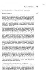
Figure 1.1: Exemplary application scenario of human-robot teams in search and<br />
rescue.<br />
The different roles of the team members in a typical search and rescue mission<br />
(cf. Figure 1.1) supported by robots might be formulated as follows. Humans<br />
are involved as operators outside the emergency area, taking over the role of a<br />
coordinator and supervisor (comparable to the commanding officer in current<br />
fire fighting missions). Inside the emergency area human rescue workers perform<br />
their scenario specific task (find and rescue victims, find the fire sources and<br />
extinguish fire, shut off gas valves and secure the surrounding etc.). New sensors,<br />
localization methods, and data transmission units can be integrated into existing<br />
rescue equipment [25]. Robots mainly provide efficient advanced exploration of<br />
the emergency area by sensor measurements. In this way, they help to reduce the<br />
risk for the human rescue workers and enable faster search of wide areas. The<br />
map that can be built from the collected data helps the operator to understand<br />
the situation and supports quick decision making and task distribution. Another<br />
important task for robots is to serve as a communication platform between a<br />
found victim (not immediately reachable by human rescue workers) and people<br />
outside the workspace (e.g. medical staff). Robots with more specific equipment<br />
can also take over more complex and specific manipulation task, e.g. shutting of<br />
3
1 Introduction<br />
gas valves. Humans may always take over the direct control of the robots.<br />
Many user requirement analyses were preformed to understand what are the<br />
needs and wishes of today’s rescue personnel for rescue robots. For instance<br />
Jones and Hinds [26] studied SWAT (special weapons and tactics) teams in training<br />
in order to transfer the observations made in multi-robot systems. Burke et<br />
al. [27] participated with robots in training of urban search and rescue personal<br />
as well as in real incidents [28], [29]. Adams [30] described requirements for<br />
human-robot interaction by analyzing human teams from a bomb squad and fire<br />
department.<br />
This work is also based on a user requirement analyses [31] performed for implementation<br />
of rescue missions [32] in the context of the "PeLoTe" project. The<br />
results provided additional important guidelines for the design of robot capabilities<br />
and the user interfaces. Many ideas and suggestions of potential end-users,<br />
who were mainly from the area of fire-fighting, entered the design processes of<br />
this work. Thus, the search and rescue scenario is used as reference application<br />
for this work.<br />
1.2 Outline<br />
The remainder of this monograph is structured as follows. Chapter 2 gives the<br />
problem analysis. It includes a detailed analysis of related work on human-robot<br />
interaction, teleoperation and relevant human factors theory. Based on this, design<br />
elements for such teleoperation systems are derived. Design background,<br />
conditions, and demands for user interfaces and driving assistance systems are<br />
given in order to support and strengthen the understanding of the overall teleoperation<br />
system including the human. Finally, the resulting system model putting<br />
the human in the loop is presented.<br />
Chapter 3 investigates two advanced technical elements for implementing a<br />
teleoperation system under considerations of the human operators’ needs. For the<br />
core component communication of a teleoperation scenario an intelligent traffic<br />
shaping mechanism is introduced and evaluated which enables to optimize the<br />
experience of the video stream in a mixed reality user interface for a navigation<br />
task. The second part of this chapter considers the fact that the human perception<br />
in the here assumed scenarios is limited by sensors of the remote machine. Threedimensional<br />
perception with a time-of-flight camera is investigated and evaluated<br />
4
1.3 Innovations<br />
with respect to calibration, parameter optimization, and pre-processing and with<br />
respect to the applicability for mixed reality user interfaces.<br />
Chapter 4 introduces the concept which enables seamless sliding autonomy<br />
during navigation of a mobile robot by a multi-modal user interface with haptic<br />
and visual components. The introduced system is based on a robust environment<br />
perception and a task specific driving assistance system, which renders the current<br />
intention of the robot’s autonomy system to a force feedback device and<br />
hereby enables the human operator to maintain situation awareness and common<br />
ground. The concept and its components are validated by extensive user studies.<br />
Chapter 5 focuses on the developed concepts for integrated, mixed reality user<br />
interfaces. It is shown how the additional information from the robots’ sensors<br />
can be used to realize advanced, fused representations of distance sensor data<br />
and camera images, which also enable a dynamic occlusion handling for an augmented<br />
reality view. In the following the mixed reality approach for graphical<br />
user interfaces for this work is discussed, and how a software framework corresponding<br />
to the needs for this kind of interfaces can be derived. Different novel,<br />
elaborated mixed reality user interfaces and corresponding evaluations are developed<br />
for team coordination but also for (assisted) direct operation of a single<br />
robot. Based on the introduced generic mixed reality user interface a new type<br />
of control of a robot with a short-term predictive user interface is proposed and<br />
analysed.<br />
In Chapter 6 a short summary, final conclusions, and directions of future research<br />
based on this work are presented.<br />
1.3 Innovations<br />
In order to enable a performant mixed reality teleoperation system for robots,<br />
a human centered design of all system elements of the teleoperation chain is<br />
required. Therefore, this thesis aims to optimize the different elements of a teleoperation<br />
scenario from an overall system performance point of view including<br />
the human as design factor. It provides consistent insights in the potential, demands,<br />
and solutions for successful application of mixed reality technologies<br />
and autonomy components for increased performance and acceptance of robot<br />
teleoperation systems.<br />
5
1 Introduction<br />
Design of Teleoperation System<br />
The human and the actual task introduce unchangeable design factors into a teleoperation<br />
system. A detailed problem analysis taking this into consideration is<br />
provided in order to achieve a task-oriented optimization of the performance of<br />
teleoperation systems from a holistic point of view. The well-known supervisory<br />
control model [33] is applied as basis for the teleoperation model. Human factors<br />
have a significant impact on the overall performance of a teleoperation system as<br />
the human is always finally the limiting factor. For this reason design goals and<br />
demands for a user centered design of the different elements of a teleoperation<br />
system are derived including the human in the loop.<br />
Application of Autonomy as Assistance Systems<br />
Nowadays, autonomy can be designed and implemented very robust in defined<br />
spatial and time horizons. Taking advantage of this fact, first a sliding autonomy<br />
concept based on a multimodal mixed reality user interface is introduced and<br />
evaluated which enables seamless transition between different levels of autonomy<br />
for the robot navigation task. The user studies with the systems prove the significant<br />
increase of navigation performance and safety. The results are also strong indicators<br />
that the proposed combination of local autonomy, haptic feedback of the<br />
systems’ intention, and augmented reality graphical user interface increase situation<br />
awareness and common ground, and reduce operators workload. Robust<br />
local autonomy also enables the introduction of a novel way to operate robots<br />
- a short-term predictive mixed-reality user interface. Hereby, a graphical user<br />
interface can be realized which allows for a combination of both advantageous<br />
viewpoint approaches - an exocentric viewpoint and a spatially correctly aligned<br />
augmented reality view. In addition, the system implements a partial decoupling<br />
of the teleoperation control loop such that the visibility of network effects in a<br />
mixed reality user interface can be reduced.<br />
Three-Dimensional Perception<br />
Various novel sensor technologies are available for robot teleoperation. We investigate<br />
novel time-of-flight cameras like the PMD camera for potential application<br />
areas in teleoperation of robots with a special focus on human-robot interaction<br />
aspects. Characteristics, calibration methods, and limitations of this novel sensor<br />
6
1.3 Innovations<br />
type are analyzed. Task-oriented optimization principles of sensor parameters<br />
are introduced and validated. The calibration results and the specific parameter<br />
adaptation schemes enabled to significantly improve the image quality for various<br />
applications in robotics (e.g. autonomous behaviors, driving assistance systems,<br />
graphical user interface). Building maps with this type of sensor as one application<br />
example is evaluated in a qualitative user study. The optimizations and<br />
findings have enabled further advanced elements in the graphical mixed reality<br />
user interfaces.<br />
<strong>Graphical</strong> <strong>Mixed</strong>-<strong>Reality</strong> <strong>User</strong> <strong>Interface</strong>s<br />
<strong>Mixed</strong>-reality provides a technological solution for many requirements of the<br />
user-centered design of the graphical user interface for robot teleoperation but<br />
also bears a lot of challenges.<br />
The camera image from a robot is the major element of mixed reality user<br />
interfaces for the operator during a navigation task. A traffic shaping method is<br />
introduced in order to optimize the experience of video streams for the human<br />
operator in ad-hoc networks. These ad-hoc networks are especially interesting<br />
for the reference application scenario search and rescue. The evaluation shows<br />
that the achievable increased robustness and stabilization of the video stream for<br />
a mixed reality user interface in such scenarios.<br />
In general robots have additional distance sensors. In this work, we take advantage<br />
of this fact by a fusion of distance sensor data (e.g. from a PMD camera<br />
or laser-range finder) with two-dimensional camera images to three-dimensional<br />
environment representation for the user interface. The combined user interface<br />
element can provide a better spatial understanding of the remote environment in<br />
an integrated, natural fashion. This way of modeling a two-dimensional camera<br />
image as a three-dimensional structure based on data from distance sensors also<br />
enables to realize communication bandwidth efficient three-dimensional visualizations<br />
on any stereo device. In addition to the improved spatial perception of<br />
the remote environment, the provided approach is also a performant solution for<br />
the dynamic occlusion handling problem of augmented reality interfaces without<br />
a priori knowledge of the operating environment.<br />
The elaborated design guidelines for the user interface are transfered to a<br />
graphical mixed reality user interface concept. A dedicated mixed reality software<br />
framework is developed which allows to quickly realize and modify mixed<br />
7
1 Introduction<br />
reality user interfaces. It also supports the usage on various stereo display devices<br />
without any further implementation effort. As the interaction role is the major<br />
design parameter for the user interface two implementations of role specific user<br />
interfaces are realized in the context of this work - one with a focus on team coordination<br />
and operation in the supervisor role, and one dedicated to the operator<br />
role for (assisted) teleoperation of a single robot. The performed evaluations of<br />
these interfaces also include the aspect of using stereo devices.<br />
Based on the results of various conducted user studies the mixed reality component<br />
of the role specific graphical user interfaces are further developed to a<br />
generic mixed-reality user interface, which makes use of the different advanced<br />
mixed-reality technologies. Hereby it enables a better adaptation to the interaction<br />
role and the task. Together with the elaborated mixed reality framework<br />
and the three-dimensional camera image modeling it can inherently be used with<br />
stereo display devices and exploit the advantages of stereo visualizations. The<br />
generic mixed reality user interface combined with a robust autonomy component<br />
also facilitates the development of the already mentioned predictive mixed<br />
reality user interface.<br />
8
2 Human in the Loop<br />
2.1 Human-Robot Interaction (HRI)<br />
Human-Robot Interaction (HRI) is an emerging field gaining more and more interest<br />
by researchers from many different fields of research [34]. Due to the technical<br />
developments of the recent years robots are applied to more and more tasks,<br />
and thus get closer to the human. Before, they were in most cases only better tools<br />
without the need for any real interaction with humans. Nowadays robots start to<br />
move out to everyday life and humans and robots have to interact in many ways.<br />
Goodrich and Schultz [35] define HRI as "a field of study dedicated to understanding,<br />
designing, and evaluating robotic system for use by or with humans",<br />
and to "understand and shape the interactions between one or more humans and<br />
one or more robots". This requires communication or more abstract an information<br />
exchange between the humans and the robots through an user interface. It can<br />
be realized in many ways - through graphical user interfaces in all its different<br />
shapes, force rendering systems, gestures, speech, etc.. Often a combination of<br />
different communication elements to a multimodal interfaces offer the optimum.<br />
HRI research is inherently interdisciplinary. Contributions from fields of cognitive<br />
science, linguistics, psychology, engineering, mathematics, computer science,<br />
human factors engineering, and design are demanded in order to successfully<br />
design HRI systems [35], and hereby open up new applications for robotic<br />
systems in everyday life. The topics which need to be covered by HRI are manifold<br />
due to the different application areas for instance in home, assistive robotics,<br />
entertainment, education, industry, search and rescue, police, military, space, etc..<br />
These applications often require very different interaction schemes between humans<br />
and robots Earlier HRI was mainly covered by the terms telerobotics and<br />
teleoperation which focused at that time on direct continuous control of a remote<br />
manipulator in industrial scenarios [33]. Robots were simply tools in a master -<br />
slave relationship. The slave robotic system reflects the movements of a master<br />
9
2 Human in the Loop<br />
system operated by a human at a remote location. Nowadays, human-robot interaction<br />
goes much beyond direct operation of a remote system and allows for<br />
a much more interactive, intelligent behavior of the robot [36]. It is important to<br />
recognize that both, human and robot, are part and need to be part of the system<br />
and design process. It is the performance of the combined system which finally<br />
matters. In this work the focus of the presented HRI concepts is on increasing the<br />
performance in remote navigation and coordination of robots in exploration and<br />
search scenarios by applying mixed reality technologies.<br />
2.1.1 Characteristics of HRI<br />
HRI as new, strongly related topic can build upon a large repository with respect<br />
to theory, methodologies and technologies from Human-Computer Interaction<br />
and Human-Machine Interaction. Adams [37] points out the importance of the<br />
user centered design in HRI and the application of already available results in<br />
human factors research. Especially the design of "humane" interfaces which is<br />
responsive to human needs and frailties is important [38].<br />
Although design of interaction between humans and robots have many comparable<br />
issues to the design of interfaces for human-computer interaction, humanrobot<br />
interaction also has some major differences [39]. Fong et al. [40] differentiate<br />
between HRI, HCI and HMI as follows : "HRI (...) differs from both HCI and<br />
HMI because it concerns systems (i.e., robots) which have complex, dynamic<br />
control systems, which exhibit autonomy and cognition, and which operate in<br />
changing, real-world environments.".<br />
Scholtz [36] identify six dimensions which need to be taken into consideration<br />
in order to successfully apply and adapt knowledge from topics like HCI and<br />
HMI:<br />
10<br />
• Different requirements based on interaction roles. The relationship between<br />
human and a robots can totally differ. A person can for instance<br />
supervise a robot, he/she can be a teammate to the robot, or he/she can repair<br />
or modify the robot. This leads to different requirements on the HRI<br />
system<br />
• Physical nature of robot. Robots are physical entities, acting in a physical<br />
world. Thus, they need to have a certain understanding and model of their
2.1 Human-Robot Interaction (HRI)<br />
environment. This needs to be transfered to the human in order to enable<br />
him/her to understand the behavior and decisions of the robot.<br />
• Dynamic nature of the hardware. HCI assumes a deterministic behavior<br />
of the computer. There is no physical change a human must track. HRI<br />
is different. Systems might change and failures might occur. It needs to<br />
be traceable by the human what changes to the system and functionality<br />
occur.<br />
• Environment in which the interactions occur. The application scenario determines<br />
the conditions in which the whole interaction system must be<br />
able to work. The environment can e.g. be very dynamical, harsh, dangerous,<br />
noisy, etc..<br />
• Number of independent systems the user interacts with. In HCI the human<br />
in general only interacts with one computer, even in collaborative systems.<br />
This can be totally different in HRI. The ultimate goal for HRI in team scenarios<br />
for instance is, that the human is able to interact with heterogeneous<br />
robots like in a human only team.<br />
• Autonomy of robots. Most of the robots can act autonomously for specified<br />
periods of time based on their own gathered information .<br />
In addition, typical design issues can be derived based on the six dimension of<br />
Scholtz [36] which need to be dealt with when designing human-robot interaction<br />
for a specific task and scenario:<br />
• What are the interaction roles between human and robot?<br />
• How is information exchanged between human and robots (e.g. graphical<br />
user interfaces, speech, gestures, etc.)? Which combination fits best for<br />
the task?<br />
• How should autonomy be designed? Is the level of autonomy changing?<br />
Who selects the level of autonomy?<br />
• What type of cooperation is realized? What kind of team setup is applied?<br />
• What is the shape of the robot (e.g. humanoid, wheeled robots, walking<br />
robots, manipulators, etc.)?<br />
11
2 Human in the Loop<br />
• What are the relationships with respect to time and space? Is the interaction<br />
synchronous or asynchronous? Are the humans and systems collocated?<br />
Yanco and Drury [41] offer a taxonomy in order to classify human-robot interaction.<br />
It enables to characterize and describe human-robot interaction along a<br />
set of categories like e.g. task type, team composition, level of shared interaction<br />
among team, interaction roles, time/space, autonomy level,... .<br />
2.1.2 Interaction Roles<br />
Robots switch over to be no longer simple stupid machines, which continuously<br />
repeat pre-programmed work sequences, but to be complex, interactive systems,<br />
which interact intelligently in various ways with humans. Thus, the different interaction<br />
roles of humans and robots need to be identified in order to optimize the<br />
interaction with respect to the requirements of the specific interaction role and<br />
the user interface accordingly .<br />
One way to differentiate between the different ways of interaction is the model<br />
from Scholtz [36]. Scholtz’s identifies five interaction roles based on the five<br />
generic supervisory’s functions in the context of human interaction with automatic<br />
systems outlined by Sheridan [33]: planning what task to do and how to do<br />
it, teaching or programming the computer, monitoring the automatic action to detect<br />
failures and deviations, intervening to specify a new goal, react on emergencies<br />
or take over manual control, and learning from experience. Scholtz mainly<br />
focuses on the support for specifying actions, monitoring actions and the intervention.<br />
The assumption is made that the robot already provides a set of basic<br />
functions and the action of reprogramming as called by Sheridan is the intervention<br />
component. The five defined interaction roles in the theory from Scholtz [36]<br />
do not consider directly the learning part on human and machine side.<br />
Based on the model from Scholtz [36] it can be distinguished between the<br />
following basic interaction roles which a human can take over when interacting<br />
with robots:<br />
12<br />
• Supervisor Interaction<br />
A human in the supervisor role is monitoring and controlling the overall
2.1 Human-Robot Interaction (HRI)<br />
situation during a task or mission. He/she evaluates the situation based on<br />
a given goal. Accordingly he/she specifies plans on a higher level. The<br />
robot’s software generates the specific actions considering its perception<br />
of its environment and the given plans by the supervisor. The supervisor<br />
can step in and specify an action or modify plans for a robot. Here the<br />
human-robot interaction focuses very much on the perception element.<br />
The supervisor can interact with a single robot, multi-robot systems or<br />
even human-robot teams. He/she is responsible for the long-term planning<br />
and the final fulfillment of the mission goal. The supervisor has to be well<br />
aware about the robots’ capabilities, problems, and current state. Typically<br />
an external coordinator of a robot team has the supervisor role in a search<br />
and rescue scenario.<br />
• Operator Interaction<br />
As operator the human will mainly act on the action level of the robot.<br />
The human will take over the operator role, when the behavior, control<br />
parameters, software, or internal models of the robot needs to be changed.<br />
According to the model longer term plans are not changed by the operator,<br />
but only by the supervisor. During direct teleoperation of a robot the<br />
human i.e. takes over the operator role.<br />
• Mechanic Interaction<br />
The mechanic role deals with changes and adaptation of the robots’ hardware.<br />
A human in mechanic role has also to take care that the applied<br />
changes to the robots have the desired effect on the behavior of the robot.<br />
• Peer Interaction<br />
In general in the peer or teammate role the human has direct interaction<br />
with the robot. The interaction is mostly on a higher level compared to the<br />
operator role. For instance a command like "Follow me, please!" would be<br />
on this higher level. In most cases a spoken dialogue or gestures comparable<br />
to that of humans working together, would be the most natural way of<br />
interaction between human and robot for this role. The peer or teammate<br />
role most often occurs when humans and robots work together co-located<br />
as a team in order to fulfill a joint task. A typical example is again in<br />
search and rescue where humans and robots enter a incident area together<br />
as team and use the complementary abilities to reach a common goal. In<br />
13
2 Human in the Loop<br />
case a human e.g. wants to change the long term plans and goals of a robot<br />
he/she would switch to the supervisor role.<br />
• Bystander Interaction<br />
In the bystander role the human has only limited or even no knowledge<br />
about the robot and the possibilities for interaction are very restricted. A<br />
bystander is in general not familiar with robots and though it is very difficult<br />
to design [42], predict and evaluate [43] interaction concepts for<br />
this role. However, for real-world scenarios it is very important to design<br />
the robot for a certain level of bystander interaction - at least to guarantee<br />
safety for people acting as bystander. A typical bystander role has a victim<br />
in a search and rescue scenario.<br />
From the explanations above it is obvious that the boundaries between the different<br />
interaction roles are very fuzzy. It is even possible that one person takes<br />
over multiple roles, switches between the roles, or that different people take over<br />
the same role. For real-world scenarios a robot has to provide the support for<br />
the interfaces and behaviors to cope with all the five types of interaction. Nevertheless,<br />
it is very important to optimize the user interfaces especially for each<br />
interaction role in order to maximize the performance of interaction on all levels.<br />
In this work the main focus lies on the supervisor, the operator interaction role<br />
and to some extend the peer or teammate role. The human in this work most often<br />
acts as operator and supervisor at the same time. Nevertheless, many of the<br />
results can be transfered to the other interaction roles. One example is the mixed<br />
reality approach to visualize system information. This provides inherently a way<br />
to intuitively present information to bystanders or mechanics.<br />
2.2 Teleoperation<br />
Teleoperation can be defined as "operating a machine at a distance" [44]. In teleoperation<br />
all decision of the operator are based on what he/she can perceive and<br />
understand from the information presented to him/her through the user interface.<br />
This is limited by the perception of the robots sensors, limitations and disturbances<br />
of the communication channel and how the information is pre-processed<br />
and presented to him/her. In addition, especially for the teleoperation of mobile<br />
robots it is necessary that all information is presented in a correct spatial relation-<br />
14
2.2 Teleoperation<br />
ship to each other and all offered autonomy and assistance functions are transparent<br />
in behavior to the human operator. Here, key issues are localization and<br />
navigation. These characteristics and demands are especially challenging as teleoperation<br />
is in most cases applied in scenarios with unknown and unstructured<br />
areas. In these application areas full autonomy is not feasible or desired. Human<br />
operator(s) are incorporated for many tasks, including perception, cognition, decision<br />
making, or navigation support. Teleoperated robots are often used in areas<br />
where it is impossible or dangerous for human to access - such as in search and<br />
rescue [28] or planetary exploration [45]. Moreover, there are other applications<br />
for the remote scenario, such as e.g. remote learning units with real hardware<br />
[23].<br />
In order to operate the robot at remote efficiently it is necessary that the operator<br />
understands the remote environment around the robot. This awareness of<br />
the remote environment and the robots surrounding is typically named as situation<br />
awareness [46], [47]. Sometimes also the term telepresence [48] is used<br />
with this respect. In contrast to the perception and understanding goal of situation<br />
awareness, telepresence aims for the feeling of being really present in the remote<br />
environment. This topic is mainly covered in the area of bilateral teleoperation<br />
[49] where a closely coupled master slave systems is designed for telepresence<br />
and stability.<br />
Sheridan’s [33] supervisory control offers a way to model the entire teleoperation<br />
system including the human, the remote environment the remote robot,<br />
different autonomy functionality, and the technical components involved. It also<br />
considers the nested control loops involved on the different levels of the teleoperation<br />
system. It is also possible to introduce the autonomous functionalities/behaviors<br />
of the system on both core design elements of the system: the user<br />
interface and the remote machine.<br />
Often the supervisory control concept is only referred to systems where the<br />
operator really takes over a role comparable to the supervisor role like defined<br />
before (cf. Section 2.1.2). But the introduced supervisory control model allows<br />
for more. Adding the extension to scale the autonomy on both sides of the introduced<br />
supervisory control model enable to model different levels of autonomy<br />
ranging from full direct teleoperation to supervising an autonomous robot.<br />
The autonomy design is also a core component and issue when designing a<br />
teleoperation system. Although full autonomy might not be reachable of feasible<br />
15
2 Human in the Loop<br />
in many scenarios and tasks, autonomous functions included into teleoperation<br />
systems can increase the performance of the teleoperation system. There are lot of<br />
experimental results which support this e.g. [50], [33], [51], [52]. Different levels<br />
of teleoperation and autonomy are thinkable. All this levels lie somewhere between<br />
the extreme cases direct teleoperation and full autonomy. In addition there<br />
are also many ways to switch between this levels and to decide who switches<br />
between these levels e.g. [53], [54].<br />
Another important issue is the communication link. Especially in bilateral teleoperation<br />
[49],[55], where a closely coupled master-slave system is realized over<br />
a communication link, parameters like for instance delay, jitter, and packet loss<br />
have a strong influence on the systems performance and behavior. In other teleoperation<br />
concepts where the abstraction between the user interface and the operated<br />
system is higher (e.g. mixes reality approaches [21], [19], [15]), the limitations<br />
are less but still significant. A consideration of the network properties can<br />
significantly improve the user interface quality [11], [10].<br />
Concluding - in order to establish high performance teleoperation systems a lot<br />
of aspects need to be considered. The three major areas are the remote machine<br />
with its perception, control/autonomy systems and actuation, and the communication<br />
channels inbetween and the user interface system on the operator side.<br />
2.2.1 Interaction between Humans and Autonomy<br />
Schilling et al. [56] define autonomy as the capability for a spacecraft "to meet<br />
mission performance requirements for a specified period of time without external<br />
support," and "to optimize the mission product, e.g. the scientific measurements,<br />
within the given constraints". For the robot scenarios this can be adapted<br />
to: Autonomy is the capability of a system to fulfill specified tasks within given<br />
performance requirements and constraints for specified periods of time without<br />
human guidance. Autonomy of robots on any level can be achieved by combining<br />
technologies from signal processing, control theory and artificial intelligence.<br />
Nevertheless even robots which are declared to be highly autonomous require<br />
interaction with humans. Various studies have been taken out, that analyze how<br />
humans can interact with autonomy, e.g. [57]. [58] gives a theoretical model for<br />
human interaction with automation. Supervisory control [33] allows the user to<br />
enter high-level commands for monitoring and diagnosis of the robot. Providing<br />
this type of control includes a certain level of autonomy of the different robots<br />
16
2.2 Teleoperation<br />
and makes the system capable to work even under low-bandwidth conditions or<br />
time delay in the communication link. <strong>Mixed</strong> initiative [53], adjustable autonomy<br />
[54] or collaborative control [59] [60] describe concepts of interaction between<br />
humans and autonomous behaviors of a robot. Collaborative control is based on<br />
event-driven human-robot dialogue. The robot asks questions to the human when<br />
it needs assistance for e.g. cognition or perception, i.e. the human acts as a resource<br />
for the robot. Since the robot does not need continuous attention from<br />
the operator, collaborative control is also useful for supervision of human-robot<br />
teams. Dias et al. [61] present challenges and a study for sliding autonomy in<br />
peer-to-peer human robot teams. [62] give suggestions for mode selection in HRI<br />
and summarizes observations from user studies. In particular it is mentioned,<br />
that users have problems to understand if the robot is in an autonomous mode.<br />
Goodrich et al. show in [63] observations from four experiments regarding autonomy<br />
in robot teams. They support the hypothesis that adaptive autonomy can<br />
increase the team performance. Stubbs et al. [64] provide results from a two year<br />
observational study with a science team applying a highly autonomous robot.<br />
They showed how common ground is disrupted on different levels of autonomy<br />
and the necessity of adapting the information and HRI communication dependent<br />
on the level of autonomy.<br />
2.2.2 <strong>User</strong> <strong>Interface</strong>s<br />
There are different ways to realize the information exchange between the robotic<br />
systems and the human. All human senses can be considered for the user interface.<br />
Classically, the three human senses sight, hearing, and touch are addressed<br />
by HRI systems in order to realize information exchange between human and<br />
robot. Thus, communication is achieved with visual, haptic or audio elements in<br />
both directions from human to robot and vice versa.<br />
Visual elements of the user interface can be implemented in various ways.<br />
While for remote operation this class of user interface elements is mainly represented<br />
by graphical user interfaces, for teammate or real peer to peer interaction<br />
gesture recognition and gestural cues of the robotic system provide a very natural<br />
visual interaction component. Hoffmann et al. [65] extensively use of gestural<br />
cues and gaze control in order to allow a human to naturally and collaboratively<br />
fulfill a task with a humanoid robot and the robot in a real teammate interaction<br />
role. It was possible to use this gestural cues to maintain common ground and<br />
17
2 Human in the Loop<br />
have a collaborative task fluently solved. Haptic or tactile elements of the user<br />
interface can be used for instance in order to give the operator feedback of forces,<br />
surfaces or distances in the remote environment. They can also be used as input<br />
control. An operator can e.g. apply a certain force to a input device, which should<br />
be applied to an object by the robot. Audio elements can be used to allow a natural<br />
conversation with speech between human and HRI system. The HRI system can<br />
give feedback through spoken language or simple tones and might understand the<br />
human through speech recognition.<br />
Dependent on the design goals and tasks assigned to a HRI system, any of<br />
these ways of communication can be combined to multimodal interfaces between<br />
human and robot like it is in human-human communication. Halme [66] shows<br />
such a concept where a human is enabled to work with a service robot in an outdoor<br />
environment on a collaborative task with various types of communication.<br />
In this work the focus is on remote operation of robots. Thus, in the following<br />
and in more detail in Chapter 5 relevant, exemplary user interfaces for the<br />
task of remote operation and coordination of robots and human-robot teams are<br />
presented.<br />
A wide range of user interfaces for the operation of mobile robots have been<br />
developed. For instance, [44] summarizes this in a review on several vehicle<br />
teleoperation interfaces. Conventional graphical two-dimensional user interfaces<br />
(e.g. [67], [68]) present the information as different interface components side<br />
by side without correlating them spatially. From the cognitive point of view this<br />
leads to the effect that the operator has to switch frequently between the different<br />
elements and has to correlate all the presented information in his mental<br />
model. These mental transformations may lead to significantly increased workload,<br />
hereby a decreased performance, most probably a decreased situational<br />
awareness and problems to maintain common ground between robot and humans.<br />
More advanced graphical user interfaces try to present the information in an<br />
integrated fashion. Kadous et al. [69] describe one of the recently successful interfaces<br />
used in the Robocup USAR competition. [21] shows an approach, how<br />
to use mixed reality for teleoperation of mobile robots in the search and rescue<br />
scenario. Nielsen et al. [70] compares a three-dimensional world representation,<br />
integrating the video as projection in front of the mobile robot, against side-byside<br />
presentation of map and video as well as two-dimensional maps together<br />
with video. An ecological interface paradigm is introduced in [52], that combines<br />
18
2.2 Teleoperation<br />
video, map and robot pose into three dimensional mixed reality display.<br />
The existing user interfaces and its evaluations offer a good insight in the interaction<br />
process and allow to derive a certain set of basic guidelines for this<br />
thesis.<br />
2.2.3 Studies and <strong>User</strong> <strong>Interface</strong> Guidelines<br />
In the area of HCI a lot of studies have been performed and guidelines have<br />
been derived. Shneiderman [71] gives a summary on design guidelines for HCI.<br />
Raskin [38] points out the importance of a "humane interface", which is also<br />
very important for HRI [37]. The Apple Human <strong>Interface</strong> Guidelines 1 give an<br />
idea of the design process of the recently commercially very successful Apple<br />
user interfaces.<br />
Experience has shown that the challenging application search and rescue is a<br />
good domain for the investigation of human-robot interaction. In this application<br />
area many studies were accomplished to determine requirements and guidelines<br />
for an efficient work between humans and robots. Navigation and solving tasks<br />
simultaneously or in joint human-robot teams assigns special requirements to the<br />
user interface.<br />
Goodrich and Olsen [72] developed a basic list of seven principles in order to<br />
implement efficient human-robot interaction based on own experiments, experience<br />
and relevant factors from cognitive information processing:<br />
• Implicitly switch interfaces and autonomy modes. Switching between different<br />
user interfaces and autonomy modes is often required in remote<br />
operation of mobile robots. This switching should happen implicitly without<br />
requiring any cognitive effort or attention by the operator. Still, it is<br />
important to give enough feedback to the operator to enable him to keep<br />
track of changes.<br />
• Use natural cues. Humans have well well-calibrated and well-practiced<br />
mental models of interaction. The use of natural cues (e.g. icons, gestures,<br />
...) allow for effective interaction as well-practiced response generation is<br />
possible.<br />
1 http://developer.apple.com/mac/library/documentation/<strong>User</strong>Experience/<br />
Conceptual/AppleHIGuidelines/OSXHIGuidelines.pdf (17.09.2009)<br />
19
2 Human in the Loop<br />
• Directly manipulate the world instead of the robot. The teleoperation system<br />
should be designed with respect to the task and not with respect to the<br />
robot and interface per se. An example would be to enable the operator to<br />
point to a location in the world and the robot will do the rest autonomously.<br />
• Manipulate the robot-world relationship. If directly manipulating the<br />
world is not possible, keep the focus on the information regarding the<br />
relation between robot, task and world.<br />
• Information is meant to be manipulated. The operator should be enabled to<br />
directly manipulate information presented to him/her in order to perform<br />
a task.<br />
• Externalize memory. The short-term memory of the operator is heavily<br />
used for remote operation of robots in order to fuse and maintain relevant<br />
information from the robot. Thus, information should be presented in an<br />
integrated fashion and important information should be made available as<br />
history in the interface.<br />
• Support attention management. At lot of information is presented to the<br />
operator. If the interface has no good attention management the operator<br />
will most probably miss relevant, critical information.<br />
Yanco et. al [73] performed a case study for the mobile robots designed for<br />
a rescue robot competition 2002. Based on their observations they derived the<br />
following guidelines for the interface:<br />
20<br />
• There should be a map allowing the operator to keep track of where the<br />
robot has been.<br />
• Sensor information should be fused in order to lower the cognitive load of<br />
the operator.<br />
• For multi-robot operation a single display should be used.<br />
• Minimize the use of multiple windows.<br />
• Provide spatial information about the robot in the environment and especially<br />
the robot’s immediate surrounding.
2.2 Teleoperation<br />
• Provide help on deciding which level of autonomy is most suitable.<br />
Scholtz et al. [74] also derived guidelines for teleoperation interfaces in the<br />
field of urban search and rescue (USAR) from an analysis of the observations<br />
of the RoboCup USAR competition. <strong>User</strong> interfaces for the remote control of a<br />
mobile-robot in USAR scenarios require:<br />
• A frame of reference to determine the position of the robot relative to the<br />
environment.<br />
• Indicators for the health and status of the robot.<br />
• Information from multiple sensors presented in an integrated fashion.<br />
• Automatic presentation of contextually-appropriate information.<br />
• As the main feedback of the robot, the camera image, might suffer from<br />
disturbances (e.g. communication problems or brightness), it is recommend<br />
to supplement the video by other sensors.<br />
• The ability to self inspect the robot body for damage or entangled obstacles.<br />
Burke et al. [27] participated with robots in training of urban search and rescue<br />
personal. They point out the large amount of effort required by the humans<br />
to percept and comprehend the information (>50% of the time) delivered by the<br />
robot in this exerices. Most of the studies and guidelines are based on designed<br />
experiments/tests and competitions. By contrast Murphy and Burke [29] compiled<br />
a list of four lessons learnt from the experience of applying mobile robots<br />
in urban search and rescue operations during real disasters (World Trade Center,<br />
2001; Hurricane Charley, 2004; and the La Conchita mudslide, 2005) and nine<br />
high-fidelity field exercises:<br />
• Building and maintaining situation awareness, not autonomous functions<br />
(e.g. autonomous navigation) is the shortage in robot operation.<br />
• The robot should be considered as a source for information, not as something<br />
that needs to be controlled. The team members should be able to<br />
exploit it as an active information source through the provide HRI system.<br />
21
2 Human in the Loop<br />
• Team members use shared visual information for building shared mental<br />
models and facilitating team coordination.<br />
• Both victims and human rescuers interact with the robot socially.<br />
Steinfeld [75] provides a set of more technical hints based on interviews and<br />
hereby experience of six experts in robotics. Many concepts presented in this<br />
work are also based on a user requirement analyses [31] performed for implementation<br />
of rescue missions [32]. The results provided additional important<br />
guidelines for the design of robot capabilities and human interfaces. Many of<br />
the functionalities provided by the presented interfaces in this work are based on<br />
ideas and suggestions of potential end-users, which were mainly from the area of<br />
fire-fighting.<br />
2.3 Human Factors<br />
The overall teleoperation system performance is always limited by the human<br />
and the information which can be delivered to the human from the limited remote<br />
sensing of the robot. To optimize the presentation of the limited information from<br />
the remote environment and the robot, the user interface needs a careful consideration.<br />
It is the basis to understand the current situation and to make decision no<br />
matter what level of teleoperation is used - direct teleoperation or supervision of<br />
a robotic system with high-level commands only. In order to design an effective,<br />
efficient and usable human-robot interface it is necessary to include the user’s<br />
perspective in the entire design and development process [37]. This is typically<br />
termed as user centered design. It demands to understand and incorporate the results<br />
and theories from technologies like telepresence and from human factors<br />
research, like situation awareness, common ground, operator workload, and spatial<br />
cognition in the design process of novel human-machine interfaces in order<br />
to reach maximum performance.<br />
2.3.1 Telepresence<br />
Steuer [48] defines telepresence "as the experience of presence in an environment<br />
by means of a communication medium". This means that the human operator receives<br />
enough information from the remote environment and the remote machine<br />
to feel physically present in the remote scenario.<br />
22
2.3 Human Factors<br />
A lot of work with respect to telepresence is performed in telerobotics [33].<br />
Typically this type of telepresence in HRI is investigated with haptic systems<br />
(e.g. [76]). The challenges to keep these systems passive, robust, and transparent<br />
are especially high. The operator directly commands a master system, the<br />
generated inputs are transmitted over a communication network, rendered to a<br />
slave system, and the resulting displacements are send back to the operator. This<br />
closely coupled master-slave systems are covered by the research area of bilateral<br />
teleoperation [49].<br />
In this work telepresence only plays a minor role as telepresence not necessarily<br />
leads to the maximum achievable task performance. In many applications the<br />
feeling of "being there" is not essential compared to situation awareness and common<br />
ground. Here, often systems which do not one-to-one render the gathered<br />
information from the remote environment achieve better results. Nevertheless, a<br />
lot of technologies and findings can be adapted to the demands of a task-oriented<br />
user interface.<br />
2.3.2 Situation Awareness<br />
A very precise definition from Endsley is cited in [46] - Situation awareness (SA)<br />
can be defined as "the perception of the elements in the environment within a<br />
volume of time and space the comprehension of their meaning and the projection<br />
of their status in the near future". This already indicates the three levels of the<br />
situation awareness model. The first fundamental level is the perception where<br />
most of the SA errors occur. The second level is the comprehension. This level<br />
deals with how people combine, interpret, store, retain and integrate information.<br />
The third level is projection. This level of SA is reached by operators which have<br />
the highest understanding of the situation and are able to project the situation in<br />
the future.<br />
In the field of operating mobile robots, Murphy et al. [29] showed that this situation<br />
awareness is even more important than any autonomy or assistance function<br />
implemented in the robot. Especially for the application in the challenging search<br />
and rescue scenario, it emerged that situation awareness is the major bottleneck.<br />
Due to the importance, a lot of studies are performed in the area of HRI with respect<br />
to situation awareness, e.g. [30], [77], [78], [79], [80]. Adams [81] presents<br />
a concept to adapt the human situation awareness to unmanned vehicle awareness<br />
including automation aspects.<br />
23
2 Human in the Loop<br />
Todays systems in HRI generate a large amount of data and information. In<br />
order to generate and maintain situation awareness it is very important to filter<br />
out the information which is really needed, when it is needed and how it should<br />
be presented in an optimal way. It is generally accepted, that more data is not<br />
necessarily more information. Data overload is one aspect which can have negative<br />
effects on SA. It is very important in the user interface design process to<br />
avoid typical traps which have a negative effect on the situation awareness. Bolstad<br />
et al. [47] identify eight "SA-demons" which might have negative effects<br />
on SA: attentional tunneling; requisite memory trap; workload, anxiety, fatigue,<br />
and other stressors; data overload; misplaced salience; complexity creep; errant<br />
mental models; and out-of-the-loop syndrome.<br />
Common Situation Awareness<br />
Common situation awareness or also called common presence [82],[83],[84] is a<br />
technical concept to transfer task related knowledge between humans and robots.<br />
It is based on a virtual model of the environment to which all entities (humans<br />
and robots) involved in a cooperative task contribute information. This model<br />
provides the interfaces such that both robots and humans can understand the information<br />
in the same way through their specific cognition system. The concept<br />
strongly relies on localization and up-to-date map information. Thus, both humans<br />
and robots require localization systems and optionally mapping abilities.<br />
For humans this can be achieved by a personal navigation system like introduced<br />
in [84], [85]. Driewer [86] presents a related extension to the situation awareness<br />
model for human-robot team setups.<br />
2.3.3 Common Ground<br />
The common ground framework [87] was actually developed to understand communication<br />
and collaboration between humans. Nevertheless, it is also a key issue<br />
for HRI, as the involved human also needs to have some common ground with<br />
the robot in order to come to decisions. Common ground is needed for any coordination<br />
of a process between independent entities, what means that between the<br />
coordinating entities is mutual knowledge, mutual beliefs, and mutual assumptions.<br />
It is also necessary to continuously update the common ground. In order<br />
to properly update common ground a so called grounding process is needed in<br />
24
2.3 Human Factors<br />
which the entities try to reach the mutual belief. Grounding in HRI is especially<br />
needed when (as in most scenarios) autonomy comes into play. The interaction<br />
system needs to support grounding processes such that the human is able to form<br />
mental models of robots how the robots collaborate. In most interaction systems<br />
there is no way of reasoning why a machine is doing what, although it is a very<br />
important issue to enable a human to collaborate with a robot comparable to human<br />
human collaboration.<br />
Jones and Hinds [26] made a study on SWAT (special weapons and tactics)<br />
teams and how they coordinated and maintain common ground inside the team<br />
during their extreme missions. They use these results to adapt their user interfaces<br />
and show how important common ground is when the entities are not located next<br />
to each other. Stubbs et al. [88] give some examples of information which should<br />
be fed back to a human operator or supervisor, e.g. technical information about<br />
system status, status of activities requested by the human, exact information about<br />
failures and its reasons, and information about constraints under which the robot<br />
operates.<br />
Stubbs et al. [64] present a study on teamwork with a science team, an engineering<br />
team, and a mobile robot. Their results also show that grounding is a key<br />
issue in HRI. They state different autonomy levels of the robots require different<br />
information to be exchanged in the team in order to enable the grounding process<br />
inside a human-robot team. Also the way of information exchange very much<br />
depends on this autonomy.<br />
There is a clear overlap between situational awareness and common ground. In<br />
HRI the common ground focus on whole information exchange and collaboration<br />
process of human and robot, while situation awareness focus more on the user’s<br />
information needs.<br />
The robot’s abilities for grounding are especially desirable in interactive social<br />
robots [89] in order to make the robot more natural and efficient. As it very much<br />
supports the situation awareness, the common ground and grounding framework<br />
is also very important when designing teleoperation systems. It allows for more<br />
efficient user interfaces with better performance results. In teleoperation system<br />
which support grounding in a very good way, a much better acceptance of autonomy<br />
and assistance functions of the robots can be expected.<br />
25
2 Human in the Loop<br />
2.3.4 Workload<br />
Workload covers mental and cognitive workload as well as physical and temporal<br />
workload [37]. A high workload can e.g. lead to reductions in vigilance and<br />
problems to maintain accuracy. The same can be the case for very low workload<br />
because the operator is under stimulated, what might lead also to reduced vigilance,<br />
boredom, etc.. The mental processing capacity varies from human to human.<br />
This mental capacity can be influenced by many circumstances, e.g. stress,<br />
lack of sleep, environmental conditions, .... If the mental workload is too high, the<br />
operator may take wrong decisions. If the mental work load is too low, the operator<br />
may not properly monitor the robot and loose track of what is currently ongoing,<br />
such that he/she get problems to maintain situation awareness and common<br />
ground. Mental workload can be optimized by a good task distribution between<br />
operator and robot. It is essential in HRI design and development to address this<br />
topic, such that the operator is not continuously under or over loaded. In some<br />
cases additional mechanisms might be needed to adapt the task allocation according<br />
to the current operator’s workload.<br />
2.3.5 Spatial Cognition<br />
Spatial relations and spatial cognition play a key role in teleoperation and navigation<br />
tasks for robots. Related to this there are various aspects which require<br />
consideration when designing a user interface:<br />
• perspective taking of the human operator. The operator needs to be able to<br />
take over different frames of reference in HRI systems. This needs to be<br />
supported by the HRI system.<br />
• mental transformations between user interface elements. The user interface<br />
itself has in general different frames of reference. Thus, a lot of mental<br />
transformations are required by the operator in order to fuse the different<br />
information in his/her mental model<br />
When people communicate about physical spaces and tasks, perspective taking<br />
plays a substantial role. People switch perspective around 45% of the time<br />
when they talk without being interuptted [90]. For HRI systems a comparable<br />
importance can be identified. HRI system need to be able to meet perspective<br />
taking demands, in order to optimize the information exchange between human<br />
26
2.3 Human Factors<br />
and robot. Trafton et al. [90] analyze perspective taking in HRI for a collaborative<br />
tasks between human and robot for a space scenario. HRI system should be<br />
able to solve ambiguity if it occours. Fong et al. [91] show an system architecture<br />
for solving collaborativly tasks in human-robot teams also for the space scenario,<br />
which has a dedicated component ("Spatial Reasoning Agent") responsible to<br />
cover the demands of perspective taking in the setup human-robot team. Five<br />
perspective taking frame of references can be identified when communicating in<br />
HRI systems:<br />
• exocentric (e.g. "move in northern direction")<br />
• egocentric (e.g. "move to my left side")<br />
• addressee-centered (e.g. "move to your left")<br />
• object-centered (e.g. "move to the table")<br />
• deictic (e.g. "move over there")<br />
Perspective taking is a major issue for real peer-to-peer human-robot interaction<br />
and in human-robot teams. For remote operation at first the different frames<br />
of reference which can occur in an user interface need to be considered. A lot<br />
of mental workload of the operator is caused by effort required for mental transformations.<br />
Mental transformations are needed to fuse the delivered information<br />
by the user interface in one mental model of the operator. This may significantly<br />
reduce the overall system performance.<br />
Wickens et al. [92] analyses the implications for the user interface design with<br />
respect to human performance limitations related to mental transformations in order<br />
to support the operators understanding of three dimensional spatial information<br />
and motion. Six basic frames of reference for the operator can be identified<br />
in a teleoperation system:<br />
• World frame. This is global frame of reference in which operation occurs.<br />
• Ego frame. Typically the location of the observer/operator.<br />
• Head frame. The orientation and location of the operator’s head with respect<br />
to the trunk.<br />
• Vehicle frame. The frame associated with the operated vehicle.<br />
27
2 Human in the Loop<br />
• Display frame. The frame of reference of information on a display.<br />
• Control frame. The frame of reference of control input devices.<br />
Different user interface components might even introduce more frame of references<br />
in the system. Assuming at maximum six degrees of freedom (three for<br />
position and three for orientations) per frame of reference already shows the complexity<br />
for the human to match them. It even gets worse if one considers that<br />
frames of reference can also have motions in all degrees what leads to another<br />
six degrees of freedom. Thus, a key design criteria is to setup a user interface<br />
with the demanded information while minimizing the needs for mental transformations<br />
which corresponds to the task. It might not be possible or undesired to<br />
avoid all mental transformations. Thus, it is important to look at the different<br />
costs for mental rotations. Hereby the task is very important. Wickens et al. [92]<br />
provide an analysis on these costs. A key finding is that mental rotations have<br />
higher cognitive demands than translations. The costs for mental rotations are<br />
not linear. For example if an operator has two maps which have a rotational misalignment,<br />
the cognitive demands increase with a higher misalignment. Over 45<br />
degree of misalignment these demands are significantly higher. A major design<br />
implication from the findings is that for travel or navigation tasks, the heading<br />
of the vehicle should always correspond with the upward direction of the map in<br />
contrast to fixed north-up maps. Interestingly, a three dimensional scenario and<br />
a two dimensional map where the forward direction (3D) and upward direction<br />
(2D) correspond can easily be matched by the operator. If two or more user interface<br />
elements show the same scene in different frames of reference, the frame<br />
matching of the operator is supported by applying the concept of "visual momentum".<br />
Common elements need to be visualized similar and highlighted in both<br />
representations.<br />
The results of the different studies in the area of perspective taking and spatial<br />
reasoning/thinking clearly point out the importance to minimize the amount of<br />
different frames of reference to those absolutely necessary. The needed mental<br />
transformations by the operator need to be optimized for the task when designing<br />
user interfaces for HRI.<br />
28
2.4 Evaluation of Human-Robot Interaction<br />
2.4 Evaluation of Human-Robot Interaction<br />
In order to evaluate the performance of human-robot interaction systems both the<br />
performance parameters of the technical components as well as the performance<br />
parameters of the involved humans need to be considered. The evaluation of the<br />
human robot system from a holistic point of view is difficult and complex. It often<br />
requires a limitation to specific task-related parameters.<br />
A lot of evaluation methods already exist in HCI. One example is the "Goals,<br />
Operators, Methods and Selection rules" (GOMS) method [93][38]. It provides<br />
an analytical way to quantitatively evaluate user interfaces without users and<br />
to hereby predict the performance of a system. Another analytical approach is<br />
the measurement of interface efficiency [38] based on information-theoretic concepts.<br />
Drury et al. [94] provide a case study on how to apply GOMS for HRI.<br />
Clarkson and Arkin [95] provide hints how heuristic evaluation from HCI can be<br />
adapted to HRI.<br />
HRI research showed the importance of human factors for HRI [37] like for<br />
HCI. Thus, the user should be involved in the whole design process. Especially<br />
the final evaluation has to be performed with users. Due to the complexity, HRI<br />
systems are very difficult to quantitatively evaluate and compare. Thus, it would<br />
be even more important to have standards to evaluate HRI systems in order to<br />
identify interdependencies and key influencing factors. Human factors research<br />
provide a good background and models to explain different effects of systems,<br />
their elements and functionalities on human robot interaction. But often these<br />
human factors are difficult to measure directly. The NASA TLX (Task Load Index)<br />
[96] is a widely used [97] method to subjectively assess the workload of an<br />
operator through a rating of the demands on different sub-scales. The SAGAT<br />
[98] test for instance is designed to measure situation awareness directly on all<br />
three levels of situation awareness. The tested system is frozen at selected random<br />
times and the user is asked a set of questions. The answers can be compared<br />
to the real situation and provide an immediate objective feedback on situation<br />
awareness. Drury et al. [80] propose the LASSO technique to evaluate situation<br />
awareness along five awareness categories: location awareness, activity awareness,<br />
surroundings awareness, status awareness, and overall mission awareness.<br />
The major data source for the evaluation here is the comparison of utterances<br />
during the test runs (think aloud approach) with the situation at that time.<br />
29
2 Human in the Loop<br />
Many approaches exist to find metrics to evaluate human-robot interaction e.g.<br />
[36], [72], [73], [74]. Steinfeld et al. [99] suggests a summarized set of common<br />
metrics for HRI. Due to the incredibly large range of robot applications the focus<br />
of these metrics is on task-oriented mobile robots. These metrics are applied<br />
as experimental design background for this work. Thus, in the following these<br />
metrics are shortly introduced. Five task categories are selected. The navigation<br />
task covers all related to global, local navigation including obstacle encounter.<br />
The perception task relates to task like search, surveillance, target identification<br />
but not to perception required by other tasks. The management task covers the<br />
coordination and management single entities or groups of a human-robot team.<br />
For the manipulation task there is a direct physical interaction between robot and<br />
environment. Social tasks are all tasks related to social interaction between humans<br />
and robots e.g. in health care. Task metrics for these five task categories can<br />
include:<br />
30<br />
• Navigation. Effectiveness measures: percentage of navigation task completion,<br />
covered area, deviation from planned route, number of successfully<br />
avoided obstacles or overcome obstacles; Efficiency measures: time<br />
for task completion, time operator needs for the task and average time<br />
for obstacle extraction; Workload measures: operator interventions, average<br />
time for an intervention, effectiveness of intervention and the ratio of<br />
operator time to robot time.<br />
• Perception. Passive perception (interpretation of received sensor data) -<br />
Identification measures like percentage detected, recognition accuracy;<br />
Judgment of extent measures like absolute and relative judgment of distances,<br />
sizes; Judgment of motion like absolute or relative velocity to other<br />
objects.<br />
Active perception: (actively obtaining sensor readings in order to e.g. solve<br />
a problem or reach confidence about a situation) - Active identification in<br />
addition includes e.g. the time or effort to confirm identification and improvements<br />
and the overall effort; Stationary search measures like e.g.<br />
accuracy of detection; Active search measures like e.g. time and effort,<br />
number of identification errors.<br />
• Management. Fan out [72], Intervention response time, level of autonomy<br />
discrepancy.
2.5 Designing the Teleoperation System<br />
• Manipulation. Degree of mental computation, contact errors (unintentional<br />
collisions).<br />
• Social. Metrics for social robots, differ from the more performance oriented<br />
metrics for the other categories. Metrics are interaction characteristics,<br />
persuasiveness, trust, engagement, and compliance.<br />
For this work the task specific metrics for navigation, perception and management<br />
are most relevant. The task specific metrics are complemented in [99] by<br />
the following common metrics:<br />
• System performance. Quantitative performance measures effectiveness<br />
and efficiency, subjective ratings, appropriate utilization of mixed initiative.<br />
• Operator performance. Situation awareness, workload, accuracy of mental<br />
models of device operation.<br />
• Robot performance. Self-awareness of the robot, awareness of human, autonomy.<br />
Task-oriented performance measurements allow for an evaluation and can be<br />
explained with the help of models from human factors in many cases. Still qualitative<br />
results from the user tests provide important aspects for the system evaluation.<br />
This can be gained through questionnaires and observations during the<br />
experiments. Thus, in this work a combination of quantitative performance measurements,<br />
subjective ratings of the test participants and qualitative observations<br />
are used to evaluate the presented concepts.<br />
2.5 Designing the Teleoperation System<br />
2.5.1 Model of the Teleoperation System<br />
The supervisory control model is often used for teleoperation systems. Sheridan<br />
[33] defines that supervisory control in the strict sense means that one or more<br />
human operators intermittently programs and continuously receives information<br />
from an system which itself closes an autonomous control loop between sensors<br />
and actuators of the machine. In the less strict sense according to Sheridan the<br />
31
2 Human in the Loop<br />
autonomous control loop is not necessarily needed. Sheridan developed the manmachine<br />
system diagram for the supervisory control model which provided the<br />
basis for the diagram in Figure 2.1. Although a great development of technologies<br />
and concept has taken place in the last years, the basic underlying conceptional<br />
model can still be applied to most teleoperation systems. While earlier manual<br />
control and direct teleoperation were really direct by means of directly interconnected<br />
inputs, which are provided to the human operator, with actuators of<br />
the operated machine, nowadays almost all systems include autonomous control<br />
loops to a certain extent.<br />
Figure 2.1 shows the adapted model which served as basis for this work. On<br />
the one end the human interacts with input devices with the human interactive<br />
system and receives information rendered on any kind of rendering device. On<br />
the other end the task interactive system interacts with the remote environment<br />
through its actuators and gathers information about the environment and situation<br />
through its sensors. Both systems exchange information through communication.<br />
It provides also the different components, parameters and technologies which<br />
influence the elements and its nested control loops and information channels of<br />
the model. The ten basic closed control loops of such systems are shown. The<br />
level of autonomy which can be modeled with this approach can be somewhere<br />
on the continuum between direct operation and full autonomy. Current research<br />
shows that autonomy has often reached a level where the one way relationship<br />
of a human only commanding and receiving information is broken up. Concepts<br />
are available where a more bilateral relationship is reached between humans and<br />
robotic systems. Initiative can also be taken by the robotic systems [51]. Hereby,<br />
a human can also be used by the robot as information source and ask for help to<br />
solve a task. In order to use the heterogeneous capabilities in human-robot team<br />
in an optimal way and to achieve optimal team performance, this new relationship<br />
is needed.<br />
The design constraints and limitations for a teleoperation system can be found<br />
at the top and the bottom of the list provided in Figure 2.1 - the human factors<br />
and the task related factors. These factors and constraints for a specific task or<br />
application can only be changed marginally. They determine the optimum which<br />
can be reached at maximum. Everything in-between is a matter of research and<br />
development to reach the optimal system. Each of the components has a more or<br />
less task depending influence on the system performance, which raises the need<br />
32
2.5 Designing the Teleoperation System<br />
Figure 2.1: Control loops based on the supervisory control model (adopted from<br />
[33]) and related system elements/parameters for a teleoperation system<br />
for a mobile robot.<br />
to look at and design such systems from the overall system perspective.<br />
Figure 2.1 provides a teleoperation task related interaction relationship between<br />
humans and an robotic system inside a human-robot team. The extension<br />
of the supervisory control concept for entire human-robot teams which also very<br />
much influenced the work presented here can be found in [86].<br />
Breaking it down to a technical data flow model for a specific teleoperation<br />
system inside a human-robot team, the model in Figure 2.2 can be derived. It<br />
shows where which data is generated, where information is processed and where<br />
potential disturbances can occur. Information processing and autonomous functionalities<br />
can be realized on both sides of a teleoperation system. This very much<br />
depends on the task and the corresponding constraints.<br />
33
2 Human in the Loop<br />
Figure 2.2: Technical data flow model for the proposed teleoperation system for<br />
a mobile robot.<br />
Concluding, when designing a human-robot interaction system, it needs to be<br />
considered that the human always is included in the control loops of the overall<br />
system. The system are designed to support humans, hence the human is always<br />
needed in the design process and the operation. As robots are getting closer to<br />
the human, HRI is a quickly growing field in recent years. The complexity of parameters<br />
influencing HRI systems and teleoperation system in particular, which<br />
can be seen in Figure 2.1 and 2.2 reveal the need for a system perspective of the<br />
system design and to put "the human in the loop".<br />
2.5.2 Design Goals and Demands<br />
In this thesis new concepts and components for advanced teleoperation systems<br />
are developed and evaluated. As reference task navigation of mobile robots and<br />
exploration with mobile robots is considered. In the following a brief outline of<br />
design goals and demands is given which has been elaborated based on literature<br />
and own tests and experience. It serves as guideline for a task oriented teleoperation<br />
system performance optimization in this thesis.<br />
Design Goals for the <strong>User</strong> <strong>Interface</strong>s<br />
The most significant influence on the overall teleoperation performance has the<br />
interface between the human operator and the system. On the one hand the user<br />
interface provides feedback from the operated robot in the remote environment.<br />
On the other hand it enables the user to give commands and thereby control the<br />
34
2.5 Designing the Teleoperation System<br />
robot through specific input devices. The feedback component can be realized by<br />
any combination of elements addressing the different senses of the human (e.g.<br />
visual, audio, haptic,...). As input devices also very different devices and their<br />
combinations are possible. The spectrum ranges from simple keyboard/joystick<br />
inputs to speech recognition, user tracking and gesture recognition systems.<br />
The different design goals for the user interface and the most important challenges<br />
can be summarized as follows:<br />
• Design an integrated display. An integrated display for the user interface<br />
should be used in order to display gathered information and sensor data<br />
which has a spatial relationship to the environment or robot, at the correct<br />
spatial location. Appropriate representations of the environment as<br />
platform for the integration of the information is needed. It should be possible<br />
that the human can reference information to certain locations through<br />
landmarks and spatial cues. The selection of viewpoints should be enabled<br />
in the integrated display. It is important to provide the operator enough information<br />
to reference the viewpoint change spatially.<br />
• Minimize mental transformations. The need for mental transformations<br />
should be minimized as far as possible without disturbing natural relationships.<br />
This includes all interface components provided to the operator, e.g.<br />
graphical user interface and force feedback components and input devices.<br />
If mental transformations are needed, avoid larger mental rotations.<br />
• Use visualizations which are natural to the human and natural cues. It<br />
is helpful to make use of the mental models of interactions and objects<br />
each human already has. Humans and machines work with different mental<br />
models. The user interface needs to be able to provide a seamless translation<br />
between these models.<br />
• Reduce user interface elements. Minimize the different elements of the<br />
user interface to the needs of the current task and situation. Information<br />
which is not needed should be faded out. If information can be fused naturally,<br />
it should be present in a combined user interface element. If it is<br />
needed that different elements show the same information in different context<br />
(e.g. viewpoint) it is important to provide the operator matching cues<br />
between this elements.<br />
35
2 Human in the Loop<br />
• Support attention management. The operator’s attention needs to be directed<br />
to crucial information. This might for instance be information<br />
which requests immediate action or information which is needed to maintain<br />
situation awareness or common ground.<br />
• Externalize memory. Support the operator by enabling him/her to build<br />
up a history of information insight the interface which might be needed<br />
for situation awareness. This enables to relieves the operator’s short-term<br />
memory from memorizing all necessary information in order to keep track<br />
of what happens and to fuse it his mental model.<br />
• Support gaining and maintaining situation awareness. Support for gaining<br />
and maintaining situation awareness is needed in different categories. With<br />
respect to the current situation knowledge about the surrounding local environment<br />
is needed and a basic knowledge in which global environment<br />
the whole thing takes place is needed. With respect to the mission and<br />
the task, awareness about the current goals, the current task allocation and<br />
the progress of the different task is needed. If multiple entities cooperate<br />
information of the work load, work progress and allocated task might be<br />
necessary. With respect to the robots and other entities, information about<br />
status, capabilities and behavior are needed.<br />
• Support awareness of autonomous behaviors. Autonomous functions are<br />
desirable with respect to task performance, i.e. robots can take over control<br />
about themselves by certain autonomous behaviors (e.g. obstacle avoidance).<br />
If the robots are not completely manual controlled, the human operator<br />
have to be properly informed about the action of the robot. This is<br />
needed to gain and maintain common ground between humans and robots.<br />
Otherwise, a frustration and mistrust might result. In the worst case the<br />
human operator will deactivate all support functions. At the best the user<br />
interface supports an optimal combination the the skills and capabilities<br />
of humans and robots.<br />
In the context of this thesis also a preliminary study with respect to user interface<br />
design for human-robot teams in general has been performed. Details on<br />
this can be found in [18].<br />
36
2.5 Designing the Teleoperation System<br />
Demands on the Robots and Communication System<br />
In addition to the user interface as the interface for interaction between human<br />
and the system itself in a teleoperation scenario, the other core challenge on increasing<br />
overall teleoperation performance is to optimize all the other crucial<br />
components of the teleoperation system from a system perspective and not from<br />
a single component perspective.<br />
• Implicit switching of autonomy modes. Navigation of the robots can vary<br />
from direct teleoperation to fully autonomous movements. In many cases<br />
different levels of autonomy are desirable in one mission according to current<br />
situation. Thus, switching between these functionalities should happen<br />
with minimum cognitive effort for the human operator. Ideally the<br />
levels of autonomy are not discrete but continuous.<br />
• Carefully design autonomy and assistance functionalities. Driving assistance<br />
system and autonomous functionalities should be designed and implemented<br />
very robust. Stability problems and failures can significantly<br />
disturb the teleoperation performance. Human operators will get confused<br />
and i.e. switch of this functionalities because of mistrust or in worst case<br />
even abort a mission.<br />
• Human centered environment perception and representation. The human<br />
mainly relies on visual impression in his daily life and lives in a threedimensional<br />
world. Thus, visual feedback from the environment and 3D<br />
representations are natural and can be very helpful. Some map representation<br />
correspond better to human cognition than others. For a human a<br />
topological description of a path might be more natural than a metric one.<br />
• Appropriate environment perception. Robots need sensors which are corresponding<br />
to their working environment, the application scenario and the<br />
actual task of the robot in order to support the spatial understanding of the<br />
environment. The environmental perception sensors have to provide the<br />
needed accuracy and need to enable robustness of the implemented autonomous<br />
and driving assistance functionalities according to the current<br />
situation.<br />
37
2 Human in the Loop<br />
38<br />
• Optimize communication system. All available and needed information<br />
and commands in a teleoperation system are transmitted over a communication<br />
link. Thus, significant disturbances can be induced by this component.<br />
Thus, a careful selection of the communication technologies and<br />
a careful design of protocols, communication architectures and topologies<br />
are needed.
3 3D-Perception and<br />
Communication Networks for<br />
Teleoperation Systems<br />
In order to enable a successful and an efficient operation of mobile robots from remote<br />
(no matter of the level of autonomy) a suitable communication network, and<br />
environment perception are demanded. Only well designed communication setups,<br />
a good environment perception, and its comprehension by the mobile robots<br />
and humans enable the large application potential of mobile robots, ranging from<br />
industrial transport robots [100], to robots applied in emergency operations, and<br />
search and rescue [31], [32], and robots for space exploration [56],[101].<br />
The application scenario and the type of interaction between humans and<br />
robots influences the requirements on the different communication layers of the<br />
ISO/OSI model [102]. For instance, if a robot replicates human movements in<br />
a master-slave constellation over a communication network, there are high constraints<br />
on this network (e.g. with respect to the tolerable delay). If the robot<br />
is teleoperated with a certain level of autonomy included in the teleoperation<br />
system, these requirements become already loose, or if robots cooperate autonomously<br />
and actively with humans in order to fulfill a joint mission goal, the<br />
communication network is only needed to send status updates, send findings and<br />
receive new data asynchronously from mission coordination center.<br />
In addition, for the successful application of mobile robots in dynamic realworld<br />
environments, a three-dimensional perception of the robots’ surroundings<br />
is a must - for both autonomous reactions as well as for assisted teleoperations.<br />
Currently, mostly nodding 2D laser range finder or cameras are used to retrieve<br />
3D data. In the last years the new technology of time-of-flight range cameras<br />
offer here a small and light-weight camera generating 3D images, which allows<br />
for an even better environment perception with minimal required processing time.<br />
39
3 3D-Perception and Communication Networks for Teleoperation Systems<br />
Nevertheless, for such innovative sensor principles, further research needs to be<br />
invested to characterize performance details and to optimize parameter settings<br />
for typical application scenarios in robotics.<br />
This chapter summarizes the contributions of this work related to two major<br />
components of teleoperation systems - communication and environment perception.<br />
The first part focuses on the implementation of teleoperation inside ad-hoc<br />
communication network setups for joint human robot teams. The adaptation of<br />
the usage of the application layer for mixed reality user interfaces dependent on<br />
the underlying IP based communication on top of a specific physical communication<br />
technology is considered. Therefore, an approach to optimize video traffic<br />
for teleoperation inside such a communication network for human-robot teams is<br />
introduced and evaluated. In the second part the sensor characteristics and application<br />
potential of a PMD camera for three-dimensional perception of the remote<br />
environment for mobile robots are analyzed. Specific aspects related to parameter<br />
optimization and limitations in measurements are discussed. In particular, range<br />
images in unstructured and changing scenes are of interest. Specific properties of<br />
mobile systems are taken into account to generate appropriate range images for<br />
navigation and mapping tasks in robotic applications. This is also incorporated<br />
into the considerations and developed concepts in Chapter 5. Compared to other<br />
related work, here the focus is on the human point of view. Thus, based on the application<br />
example of local 3D panoramas a qualitative user study was performed<br />
in order to get an idea how good humans can orient, navigate, and detect objects<br />
in this type of 3D environment representations.<br />
3.1 Enabling Technologies<br />
3.1.1 Communication Technologies<br />
Nowadays, a lot of standard communication technologies are available in the<br />
consumer market, which are affordable and also well tested. Some of them already<br />
offer the basic characteristics and designs in order to be applied in systems<br />
where humans and robots work together. Setups of communication networks for<br />
human-robot systems need to be able to support different classes of communication<br />
traffic. Dependent e.g. on the tasks, the autonomy of the different systems,<br />
the team configuration, and also the type of user interface, different demands on<br />
40
3.1 Enabling Technologies<br />
the communication network arise. For mixed reality user interfaces the position<br />
in the virtual continuum (cf. Figure 5.1) has a significant influence on which requirements<br />
can be met. For instance an augmented reality interface where the<br />
camera image as real world component is in the focus, has high demands on the<br />
bandwidth and the jitter of the communication link compared to a pure virtual<br />
user interface which can work more or less asynchronously.<br />
Most often, wireless communication is demanded and chosen to distribute and<br />
share information between robots or between humans and robots forming a joint<br />
team. This includes the transmissions of sensor data from the robots, observations<br />
from the humans, commands, and plans to the different team entities from the human<br />
coordinators. Compared to very specialized missions like Mars exploration<br />
with Rovers [101] or short range investigation of collapsed buildings [29], where<br />
also tethered communication can be applied, for almost all applications of mobile<br />
robots in changing environments, changing operation areas, and changing tasks<br />
this wireless communication is a must. While in the past mainly proprietary communication<br />
systems [68] and protocols were used for mobile robotics, nowadays<br />
a clear trend towards IP 1 based communication systems can be identified. The<br />
main drivers for this trend are the availability of well-tested, high performance<br />
communication hardware and the overall trend in the consumer and professional,<br />
industrial market to use IP based networks. The selection of an IP based communication<br />
systems enables a seamless integration of robots into existing networks.<br />
This is especially interesting in industrial scenarios, the area of service robotics<br />
and home automation. Figure 3.1 shows how a future robotic team can be setup<br />
for instance for the exemplary scenario in this work - a search and rescue mission.<br />
Future missions where humans and robotic systems work together to reach<br />
a common goal require communication networks with interfaces for heterogeneous<br />
communication technologies, systems with world-wide access to information<br />
and human expertise. Especially in the exemplary application search and rescue,<br />
where at least parts of the communication infrastructure might be destroyed<br />
in the local mission workspace, the systems in the local mission workspace need<br />
to be able to setup their own communication infrastructure on demand or bridge<br />
communication gaps. Heterogeneous communication technologies can supplement<br />
each other. In this work the two broadband communication technologies<br />
IEEE 802.11 wireless LAN and the mobile phone network UMTS as outlook are<br />
1 IP - Internet Protocol<br />
41
3 3D-Perception and Communication Networks for Teleoperation Systems<br />
considered as wireless interface technologies.<br />
Figure 3.1: Future example scenario of a heterogeneous network of mobile robots<br />
and humans working on a joint mission.<br />
As part of this work on the demands of mixed reality teleoperation systems<br />
also a simulation setup was proposed in order to test communication setups with<br />
real communication devices and without the effort of setting up the whole humanrobot<br />
team in a real environment. The communication is realized with real communication<br />
devices and the environment is simulated with a three-dimensional<br />
simulation including a good physics engine - USARSim [103][104]. Further details<br />
on this and the test runs with a distributed collaborative collision avoidance<br />
[105][106] algorithm can be found in [9].<br />
Wireless Lan In many cases IEEE 802.11 wireless LAN (WLAN) is used as<br />
underlying technology for the wireless network in-between mobile robots, humans<br />
and other systems. Nowadays, modern telecommunication equipment with<br />
small power consumption and interfaces for easy integration are available for<br />
these wireless LAN standards. Further advantages of WLAN are the availabil-<br />
42
3.1 Enabling Technologies<br />
ity of a relatively high bandwidth dependent on the standard (e.g. 802.11b max.<br />
11 MBit/s, 802.11g max. 54 MBit/s) and the high flexibility in integrating new<br />
protocols or extending features of available protocol implementations. WLAN<br />
devices can work in infrastructure mode and in ad-hoc mode.<br />
As currently the cooperation of several vehicles is very important, challenging<br />
problems like nodes acting autonomously as communication relay, a highly<br />
dynamic and variable network topology (some network nodes may leave or join<br />
the network at any time), routing problems, and several data streams and sources<br />
with different bandwidth requirements have to be solved in order to successfully<br />
setup an appropriate communication network. Often, ad-hoc capabilities have to<br />
be present to meet this needs. The usage of IEEE 802.11 wireless LAN enables<br />
to realize an affordable wireless communication which satisfies these demands<br />
for teams of mobile robots and humans.<br />
Wireless Ad-Hoc Networks Human-robot team scenarios demand for decentralized<br />
communication networks which allow for any to any communication.<br />
During the last years, several teams achieved remarkable results in the<br />
research area dynamic wireless communication network topologies. In 2007,<br />
Rooker and Birk presented multi-robot exploration with robots using wireless<br />
networks [107]. The University of Pennsylvania presented a mobile robot team<br />
connected via wireless network which performed localization and control tasks<br />
[108] in 2002. [109][110] placed relay nodes on demand to setup the required<br />
telecommunication infrastructure and in [111][112] mobile robots are used as relay<br />
nodes where each mobile node not only works as host but also as router for<br />
data packets of other nodes. In [113] a live audio and video data transmission<br />
via a multi-hop wireless network is demonstrated. In addition, several systems<br />
of rovers with autonomous functionalities [114], groups of unmanned aerial vehicles<br />
[115], as well as heterogeneous multi robot systems were proposed. For<br />
ground based systems Chung [116] presented a testbed for a network of mobile<br />
robots. In the field of rescue robotics [117], or for integrating UAVs into IP based<br />
ground networks [118], the use of wireless networks is quite common nowadays.<br />
With respect to unmanned aerial vehicles (UAVs), [119] presented a system using<br />
an access point running in WLAN infrastructure mode onboard the UAV. [120]<br />
presented a system for communication between a ground station and a UAV using<br />
WLAN in combination with a high-gain antenna and radio modem. These<br />
43
3 3D-Perception and Communication Networks for Teleoperation Systems<br />
wireless ad-hoc networks offer a lot of advantages in contrast to static wireless<br />
network configurations, but also raise a lot of new challenges in the system design.<br />
Wireless communication always implies unpredictable communication delays,<br />
packet loss, or in worst case the loss of the link, which makes the provision<br />
of the required quality for teleoperation or control tasks rather complex [121].<br />
The already mentioned ease of use, the affordable prize, small weight, and appropriate<br />
power consumption makes WLAN often a reasonable choice to set up<br />
dynamic topologies providing direct and indirect any-to-any communication of<br />
each network node. In addition, also benefits like redundant communication links<br />
in larger networks, no central administration, and a distribution of the traffic load<br />
in large networks are present. Of course, these advantages can only be used with<br />
rather complex and special routing protocols providing each node the necessary<br />
information of the network topology. The nodes itself are working as routers and<br />
must store the routing information of the complete network locally. In the field of<br />
wireless telecommunication, more than 80 different approaches for ad-hoc routing<br />
mechanisms of different types (classes) were developed. Well known classes<br />
of these protocols are pro-active, reactive, or hybrid (pro-active and reactive) protocols<br />
but also flow oriented, power aware, multicast, position based, or situation<br />
aware approaches are available. The number of implemented protocols which<br />
have reached the status to be used in lab-environments is much smaller [122] and<br />
if an appropriate real world scenario with mobile robots is considered, the alternatives<br />
are quite small. Some simulations for performance evaluations for larger<br />
scale telecommunication networks were done in the past [123][124][125] and<br />
based on [126][127][128][129]. Recently AODV, DSR, OLSR, and BATMAN<br />
and the application of multi-hop communication were analyzed with respect to<br />
mobile robot teleoperation [12][130][8]. The work published in the before listed<br />
publications served as basis for the communication of the later presented concept.<br />
Outlook - Teleoperation over UMTS connections The upcoming highbandwidth<br />
networks for mobile phones or mobile Internet like UMTS 2 offer another<br />
new widely used and commercially available technology with high potential<br />
for the application in mobile robot teleoperation. Up to now, the coverage of these<br />
networks has increased in a way that at least all bigger cities have access to broadband<br />
networks. This "everywhere availability" in large areas is a major advantage<br />
2 UMTS - Universal Mobile Telecommunications System<br />
44
3.1 Enabling Technologies<br />
for any telematic application compared to a solution where infrastructure initially<br />
has to be built up and maintenance effort is necessary. Besides the operation of<br />
mobile robots, this includes applications like tele-maintenance, tele-support, or<br />
tele-monitoring of industrial facilities. These applications in general demand also<br />
these high-bandwidth communication links. Often, an additional own infrastructure<br />
might be not feasible or possible and thus, the high-bandwidth telephone<br />
networks provide there an interesting alternative. The design of this networks in<br />
a way that they should provide a seamless transition between different communication<br />
cells, the scheduling concepts for resource allocation for the different<br />
users and the ability to work indoors to a great extend are also very promising issues<br />
for robotics. In particular, the application area of service robotics can largely<br />
benefit from these characteristics.<br />
On the other hand, the mobile phone networks like UMTS are designed for<br />
different purposes and under different constraints. Therefore, it is important to<br />
investigate the critical parameters of a communication technology like UMTS in<br />
order to adjust the possible communication parameters on the application layer<br />
in a way to realize the optimum usage of this technology for the own application,<br />
here mobile robot teleoperation. First analysis performed in the context of this<br />
thesis can be found in [7][131].<br />
3.1.2 Network Parameters and Video Streams<br />
Network parameters have a major influence on the overall performance of humanrobot<br />
teams in scenarios where remote interaction or components exist. For teleoperation<br />
or supervisory tasks typical network parameters like communication<br />
bandwidth, delay and jitter are of major importance. In teleoperation systems in<br />
general a data flow of commands and information to the robot exist and a data<br />
flow back to the operator with sensor data and in most cases a video stream.<br />
For teleoperation different levels of automation can be applied. A higher level<br />
of automation (e.g. through autonomous obstacle avoidance) in cases where the<br />
operator is able to maintain situation awareness and common ground in general<br />
leads to a better navigation performance in time and errors. In addition, a higher<br />
level of automation leads to a higher robustness against the duration of communication<br />
delays and its jitter. The results of an investigation of the influence of<br />
latency in mobile robot operation for four different levels of automation from<br />
Luck et al. [132] and own experience with such systems supports this hypothesis.<br />
45
3 3D-Perception and Communication Networks for Teleoperation Systems<br />
A video stream is still one of the most important data sources for the user<br />
while operating a mobile robot at remote. The video feedback still delivers the<br />
most and richest information from the remote environment to the operator. This<br />
detailed information from the remote site is needed to increase and maintain the<br />
situation awareness (cf. Section 2.3.2) and common ground (cf. Section 2.3.3) between<br />
robot and human operator as basis for any future decisions and commands<br />
done by the human operator. Human operators have comprehensive capabilities<br />
to interpret the displayed image information, but therefore, some constraints must<br />
be fulfilled. Constant frame rates and delays below a certain threshold are a minimum<br />
requirement to use video for teleoperation. A certain delay of teleoperation<br />
systems is inevitable but a human operator can adjust to a certain extent to it.<br />
In general it is much easier for an operator to adjust to an constant delay compared<br />
to an varying delay. The selected framerate, the resolution and the quality<br />
of the video stream determine the required bandwidth from the communication<br />
links. Dependent on the human teleoperation task different characteristics of the<br />
video stream are important. If a navigation task is considered, the most important<br />
parameters are a high frame rate, low number of frame losses, and a constant<br />
inter-arrival time between the frames. Compared to these parameters the quality<br />
and resolution of the video stream is less important for navigation. On the other<br />
hand if the human has a search task (e.g. identify objects in a delivered video<br />
stream), the quality and resolution have a higher importance than the frame rate.<br />
Sheridan [33] shows the influence and importance of framerate and resolution on<br />
the performance of a telerobotic systems.<br />
In order to compress and transmit video data a lot of standards and codecs<br />
exist. Typical examples are MPEG-1, MPEG-2, MPEG-4, DivX and MJPEG.<br />
The MPEG family and the DivX codec make use of redundancy between subsequent<br />
images in a video stream. Thus, a better bandwidth usage is possible. For<br />
MJPEG each video frame is transmitted completely and so a higher bandwidth is<br />
needed. Typically network cameras like applied in this thesis offer MPEG-4 and<br />
MJPEG video stream with different hardware compression rates. The experience<br />
with this systems showed that the selection for MJPEG is often the better choice.<br />
Although the bandwidth requirements are higher, a short communication drop<br />
out and packet loss does not cause a disturbance of a longer sequence of video<br />
frames like for the other codecs. In addition, the implemented compressions for<br />
MJPEG introduce a much lower processing delay for encoding and decoding than<br />
46
3.1 Enabling Technologies<br />
for MPEG-4, which is significant for the overall system delay in the teleoperation<br />
system.<br />
3.1.3 Three-Dimensional Perception<br />
Three-dimensional perception of the environment offers significant potential to<br />
improve navigation solutions for mobile systems. Classical approaches for 3Dimaging<br />
refer to stereo-cameras, optical flow approaches and laser range scanners,<br />
while so far in industrial applications still mainly simple and reliable 2Dsensors<br />
are in use [133]. With the progress in robotics and the movement to work<br />
environments which are not completely pre-defined anymore, three dimensional<br />
perception is essential. Today, mainly three-dimensional laser range finders are<br />
used for three-dimensional perception and mapping in robotics [134][135]. As<br />
an alternative stereo cameras provide high framerates and high lateral resolution.<br />
Nevertheless, there is still high complexity on finding disparities and calculating<br />
distances from the image pairs. In addition, the applicability very much relies on<br />
the environmental conditions (e.g. lighting, structure). As three-dimensional laser<br />
range finders systems exist with nodding 2D laser scanner, as well as high accurate<br />
3D laser scanners. The frequency of getting point clouds from this types of<br />
sensors differ from some seconds to some minutes depending on the increment of<br />
the tilt angle. In other approaches for mobile robots, two or more 2D laser scanners<br />
are mounted horizontally or vertically in order to provide a field-of-view of<br />
360 ◦ [136]. Recently also laser range finders with a horizontal field of view of<br />
360 ◦ , and a vertical field of view 26.8 ◦ like the Velodyne HDL-64 3 are available.<br />
It provides three-dimensional point clouds with a frequency of 10 Hz.<br />
All these systems are quite expensive and include complex, moving mechanical<br />
components. Thus, the newly available 3D time-of-flight range cameras provide<br />
a promising alternative to these existing techniques and attract much interest<br />
[137], [138], [139]. The following Section 3.1.4 gives a more detailed overview<br />
on this new type of cameras.<br />
3.1.4 3D-Time-of-Flight Cameras<br />
3D time-of-flight (ToF) cameras provide instantaneously a depth image of the<br />
environment, without the requirement of any further processing of the received<br />
3 http://www.velodyne.com/lidar/ (24.10.2009)<br />
47
3 3D-Perception and Communication Networks for Teleoperation Systems<br />
(a) PMD 19k (b) Swissranger SR3000 (c) PMD CamCube 2.0<br />
Figure 3.2: Example 3D-ToF cameras.<br />
data in order to get distances. In addition to the depth information for every pixel<br />
of the image, an amplitude image, and for some cameras also an intensity image,<br />
which can be interpreted as a grayscale image of the environment, is received.<br />
These compact cameras can be operated at high frame rates and do not include<br />
any mechanical moving parts, being thus very suitable for mobile systems. Figure<br />
3.2 shows two examples of ToF cameras from the leading companies PMD-<br />
Technologies 4 and Mesa Imaging 5 . The current implementations of these cameras<br />
have limitations in the field of view and the resolution. Nevertheless, these<br />
implementations already offer high potential for mobile robot applications. Table<br />
3.1 gives important characteristics of some examples for existing implementations<br />
of 3D-ToF cameras. All this 3D-ToF cameras are based on photonic mixing<br />
device (PMD) technology. Thus, in the following also the term PMD camera is<br />
used equivalent to 3D-ToF camera.<br />
Working Principle<br />
In order to understand the considerations, calibration and determined characteristics<br />
of the later Sections 3.3, and 3.4 in the following the basic working principle<br />
and important parameters are summarized. The basic equations of this section<br />
and more details on electronic principle are given in [140].<br />
A PMD camera actively sends out a modulated infrared light. In each of the<br />
pixels of the camera chip a so called photonic mixing device (PMD) or smart<br />
pixel is embedded [137, 141]. Each of these pixels allow to determine the correlation<br />
(cf. blue line in Figure 3.3) between modulated emitted reference and<br />
4 http://www.pmdtec.com/ (27.10.2009)<br />
5 http://www.mesa-imaging.ch/ (27.10.2009)<br />
48
3.1 Enabling Technologies<br />
Model Resolution Default Ambiguity Range Field of View<br />
PMD 3k-S 64×48 7.5 m 40 ◦ × 30 ◦<br />
PMD 19k 160×120 7.5 m 40 ◦ × 30 ◦<br />
PMD S3 64×48 7.5 m 40 ◦ × 30 ◦<br />
PMD A-Sample 64×48 40 m 52 ◦ × 39 ◦<br />
PMD CamCube 2.0 204×204 7 m 40 ◦ × 40 ◦<br />
Swissranger SR 3100 176×144 7.5 m 47.5 ◦ × 39.6 ◦<br />
Swissranger SR 4000 176×144 5 m/10 m 43.6 ◦ × 34.6 ◦<br />
Table 3.1: Characteristics according to data sheets of exemplary 3D-ToF cameras<br />
in standard configuration.<br />
perceived optical signal, such that the phase shift can be calculated and respectively<br />
the proportional time-of-flight and the distance.<br />
Figure 3.3: Schematic principle of phase-shift algorithm (adopted from [140]).<br />
The correlation function is sampled four times M1, M2, M3, M4 with a phase<br />
offset of 90 ◦ in-between each sample (cf. Figure 3.3). The phase shift ϕ can be<br />
calculated as follows:<br />
� �<br />
M1 − M3<br />
ϕ = arctan<br />
(3.1)<br />
M2 − M4<br />
From the phase shift ϕ the measured distance D can be derived:<br />
D = ϕ<br />
λmod<br />
· dmax; dmax =<br />
2π 2 =<br />
c<br />
2 · fmod<br />
(3.2)<br />
The maximum distance without ambiguity of the measurements dmax is determined<br />
by the modulation frequency fmod of the camera. It is half the wavelength<br />
49
3 3D-Perception and Communication Networks for Teleoperation Systems<br />
λmod of the modulation frequency. c denotes the speed of light. Besides the used<br />
modulation frequency of the camera also the illumination power of the camera’s<br />
illumination limits the maximum distance which is measurable.<br />
In addition to the distance two further values can be derived: the incident light<br />
intensity I (cf. Equation 3.3), and the correlation amplitude A (cf. Equation 3.4).<br />
The intensity value can also be regarded as a kind of grayscale value. The amplitude<br />
can be interpreted as kind of measure for the quality of a determined distance<br />
value.<br />
I = 1<br />
4�<br />
Mi<br />
(3.3)<br />
4<br />
i=1<br />
�<br />
(M1 − M3) 2 + (M2 − M4) 2<br />
A =<br />
(3.4)<br />
2<br />
Besides the modulation frequency the most important adjustable parameter<br />
for the PMD camera is the integration time τ. The integration time specifies the<br />
time in which incoming photons are considered for the distance measurement. It<br />
is comparable to the shutter speed of a standard camera. Tests with the camera<br />
showed that it is very important to adapt this integration time to the observed<br />
scenario and the task. A wrong selected integration time can cause either oversaturation<br />
or insufficient saturation and hereby invalid distance measurements. The<br />
desired optimal working range and the reflectivity of observed objects have influence<br />
on the the selection of the integration time. In Section 3.3.3 an algorithm<br />
is introduced to adapt this integration time automatically during runtime for the<br />
mobile-robot navigation tasks.<br />
Quality problems, oversaturation, or false measurements can also be caused<br />
by environmental sources like natural sunlight or artificial light sources, which<br />
have an infrared component in the wavelength of the PMD camera illumination<br />
units. Thus, older camera models like the PMD 19k cannot be used in outdoor<br />
scenarios. Newer cameras (e.g. PMD 3ks, ASample, CamCube2.0) have a technology<br />
like the Suppression of Background Illumination (SBI) [142] integrated,<br />
which enables the cameras to work to some extend also in outdoor environments.<br />
Applications<br />
Many potential applications of 3D-ToF cameras in automotive, multimedia, entertainment,<br />
robotics, and other areas have been described [139]. In automotive<br />
industry, range cameras are used for crash avoidance, as a distance sensor for<br />
50
3.1 Enabling Technologies<br />
cruise control, traffic sign detection, park assistance, or driver tracking and monitoring,<br />
e.g. [143],[140]. In the area of multimedia and entertainment 3D-ToF<br />
cameras were used for a virtual keyboard [144] and for an interactive canvas.<br />
Another application of PMD cameras which currently raised a lot of interest is<br />
gesture and body tracking e.g. for game consoles [145]. This gesture and body<br />
tracking is also of interest for future interfaces in HRI. It might enable a more<br />
natural and intuitive peer to peer interaction with robots through higher safety<br />
[146] and new ways of commanding and teaching robots even in the industrial<br />
application area. In the context of mobile robotics [138] and [147] present ideas<br />
of potential applications. In [148] and [149] a PMD camera was used for landmark<br />
detection in order to localize a mobile robot. May et al. [150] shows an<br />
approach for 3D-pose estimation in robotics. Weingarten at al. [151] described a<br />
simple obstacle avoidance and path planning with a 3D-ToF camera. Hong et al.<br />
[152] also reports about obstacle detection for AGVs (Automated Guided Vehicle)<br />
in factory environments. Sheh et al. [134],[153] investigated 3D-ToF cameras<br />
for map-building and stepfield traversal in an artificial USAR (urban search<br />
and rescue) environment. Craighead et al. [154] tested a 3D-ToF camera for use<br />
in USAR. They especially analyzed the influence of lightening conditions and<br />
movement disturbances.<br />
Hybrid systems of a PMD camera and a CCD video camera [155],[156],[157]<br />
or stereo camera [158],[149] have also been investigated. In order to fuse multiple<br />
depth images scale-invariant features can be used. Two approaches to retrieve<br />
such features from PMD cameras are presented in [159] and [160].<br />
Another application of PMD cameras would be in space robotics. If the technology<br />
proves to be applicable in space, a very promising application for this type<br />
of cameras would be e.g. spacecraft tracking for rendevouz and docking maneuvers.<br />
In the context of this thesis work also contributions to this application were<br />
made. These contributions will not be covered in this monograph. Details on this<br />
work can be found in [5].<br />
Compared to the related work described before, this thesis work investigates<br />
the application of PMD cameras for user interfaces and driving assistance systems<br />
in mobile robot teleoperation from the human point of view. Parts of the<br />
results were also published in [13].<br />
51
3 3D-Perception and Communication Networks for Teleoperation Systems<br />
X W<br />
X C<br />
Principal<br />
Point<br />
Y W<br />
(0,0,0) T<br />
Y C<br />
Z W<br />
(0,0,0) T<br />
Z C<br />
Y E<br />
X E<br />
m’<br />
Focal Length f<br />
(c X ,c Y ) T<br />
Image Plane E<br />
Figure 3.4: Geometry of pinhole camera model.<br />
3.1.5 Optical Camera Calibration<br />
Both 3D-ToF cameras and cameras for visual image capturing are optical systems<br />
which project elements of a three-dimensional world to a two-dimensional pixel<br />
array. For 3D-ToF cameras a model of this projection is required in order to transform<br />
the spherical distance values Ds[i, j] for each pixel at pixel position i, j on<br />
the camera chip to metric Cartesian x, y, z coordinates relative to the camera.<br />
For the intensity and amplitude image and visual cameras the projection model<br />
is necessary in order to find the correspondence between the three-dimensional<br />
objects and the received two-dimensional images. Thus, the application of such<br />
optical camera systems in robotics requires a careful calibration in order to gather<br />
meaningful distance information (cf. Sections 3.3, 3.4, 5.2). In the following the<br />
models for projection and calibration for optical camera systems which are used<br />
in this work are introduced. This background is necessary to understand the proposed<br />
methods and concepts in the later sections.<br />
Perspective Projection<br />
For the projection of an optical camera typically the pinhole model is applied<br />
(cf. Figure 3.4). Three basic frames of reference exist in this model - the threedimensional<br />
world coordinate frame LW , the three-dimensional camera coordinate<br />
frame LC and the two-dimensional pixel coordinate frame LE corresponding<br />
to the pixel array of the camera chip. In order to derive the transform from<br />
52<br />
m
3.1 Enabling Technologies<br />
world coordinates to pixel coordinates two transformations are required. The<br />
transformation TWC corresponding to the extrinsic parameters of a camera calibration<br />
transforms world coordinates to camera coordinates. The transformation<br />
from camera coordinates to pixel coordinates PC corresponds to the intrinsic or<br />
projection parameters of a camera. Equation 3.5 gives the needed mathematical<br />
model to project a point m = (xW,yW,zW,1) T in world coordinates to a point<br />
m ′ = (xs, ys, s) T on the two dimensional pixel array of the camera.<br />
⎛ ⎞<br />
⎛ ⎞<br />
xW<br />
xS<br />
⎜ ⎟<br />
⎜ ⎟ ⎜yW<br />
⎟<br />
⎝yS⎠<br />
= PC · TWC · ⎜ ⎟<br />
⎝zW<br />
⎠<br />
s<br />
1<br />
⎛<br />
fsx<br />
⎜<br />
= ⎝ 0<br />
0<br />
fsxαc<br />
fsy<br />
0<br />
cx<br />
cy<br />
1<br />
⎛<br />
⎞<br />
0 ⎜<br />
⎟ ⎜<br />
0⎠<br />
⎜<br />
⎝<br />
0<br />
R11 R12 R13 tx<br />
R21 R22 R23 ty<br />
R21 R32 R33 tz<br />
0 0 0 1<br />
⎞ ⎛<br />
xW<br />
(3.5)<br />
⎞<br />
⎟ ⎜ ⎟<br />
⎟ ⎜yW<br />
⎟<br />
⎟ ⎜ ⎟<br />
⎠ ⎝zW<br />
⎠<br />
1<br />
f denotes the focal length in metric units. sx and sy scale f to the unit pixels.<br />
Thus, 1 1<br />
= wp and = hp correspond to the physical width wp, and height hp<br />
sx sy<br />
of one pixel on the camera chip. During typical calibration processes as described<br />
in the later section, the focal length and the scale factors can not be derived separately.<br />
The result of an intrinsic calibration yields the combined terms fsxand<br />
fsy - the focal length fpx and fpy in pixels. However, these combined values together<br />
with the pixel array width and height allow to determine the field of view<br />
of a camera directly. No further knowledge about the physical size of the camera<br />
chip is required. By contrast the field of view calculation based only on the focal<br />
length f requires the physical size of the camera chip. With fpx and fpy the<br />
horizontal and vertical field of view FoVh, FoVv can be calculated as follows:<br />
FoVh = 2 · arctan<br />
� xmax<br />
2fpx<br />
�<br />
, FoVv = 2 · arctan<br />
� ymax<br />
xmax and ymax denote the dimensions of the camera chip in pixel.<br />
2fpy<br />
�<br />
(3.6)<br />
αc is the skew factor which is the angular relation between x and y axis of<br />
the pixel array. For available cameras this angular relation can be assumed to be<br />
orthogonal, such that αc is equal to zero, and hereby the whole matrix element. cx<br />
and cy denote the pixel coordinates of the principal point on the pixel array. The<br />
53
3 3D-Perception and Communication Networks for Teleoperation Systems<br />
matrix TWC is a standard homogeneous transformation matrix with rotational<br />
and translational components.<br />
Assuming perfect projection without distortion, the final coordinates xn, yn in<br />
the pixel array can be derived by normalizing the vector (xS, yS, s) T as follows:<br />
Distortion<br />
⎛<br />
xn<br />
⎞<br />
⎛<br />
x S<br />
s<br />
⎞<br />
⎜ ⎟ ⎜ y<br />
⎝yn⎠<br />
= S ⎟<br />
⎝ s ⎠ (3.7)<br />
1 1<br />
In most optical camera systems the real lenses compared to the before listed mathematical<br />
model show distortion effects (mostly radial and slight tangential). This<br />
is mainly due to imperfectness of the real lenses. Thus, a distortion model is<br />
needed in order to compensate this for the application in augmented reality interfaces<br />
and sensor measurements. The common distortion model in Equation 3.8<br />
was first introduced by Brown [161] and is used in many machine vision and<br />
calibration approaches (cf. Section 3.1.5).<br />
xd = xn · (1 + k1r 2 + k2r 2 + k3r 6 ) + 2p1xnyn + p2(r 2 + 2x 2 n)<br />
yd = yn · (1 + k1r 2 + k2r 2 + k3r 6 ) + p1(r 2 + 2yn 2 ) + 2p2xnyn<br />
with r = xn 2 + yn 2<br />
(3.8)<br />
Here the coefficients k1, k2, k3 correspond to the radial distortion coefficients,<br />
and p1, p2 to the tangential distortion coefficients. These distortion coefficients<br />
can be determined with standard calibration tools, and can be used with the distortion<br />
model to calculate a corrected, normalized image for further usage from<br />
the retrieved distorted image. For standard field of view cameras the radial distortion<br />
coefficient k3 is neglectable and set to zero. Thus, most calibration tools<br />
do not determine k3 by default.<br />
Camera Calibration<br />
Various calibration tools exist to determine the intrinsic and extrinsic parameters<br />
of a camera. Most of them are based on calibration models and concepts<br />
introduced in [162], [163], or [164]. For calibrations in this work the Matlab<br />
Camera Calibration Toolbox 6 by Jean-Yves Bouguet and the GML Camera Cal-<br />
6 http://www.vision.caltech.edu/bouguetj/calib_doc/ (30.10.2009)<br />
54
3.1 Enabling Technologies<br />
ibration Toolbox 7 are utilized. The basic procedure of this calibration is always<br />
that a reference pattern (here a printed regular black and white chessboard) is captured<br />
with a camera from different point of views. Based on these images and the<br />
known reference pattern at first the intrinsic and distortion parameters are derived<br />
through optimization approaches. With the now known intrinsic parameters, for<br />
each of the images the relative position and orientation - the extrinsic parameters<br />
- to the reference pattern can be determined.<br />
3.1.6 Sensor Data Fusion, Localization and Mapping<br />
For robotic systems sensor data fusion from different data sources is often required.<br />
As example Kalman-Filter and various modifications like e.g. the extended<br />
Kalman-Filter (EKF) or analytical optimization methods are used for sensor<br />
data fusion. In particular, sensor data fusion is needed for localization and<br />
mapping in order to make use of the complementary advantages and properties<br />
of the different systems.<br />
There are different sensor systems which allow to determine the absolute position<br />
of a robotic system. The global positioning system (GPS), Galileo, and various<br />
systems which require to setup an specific infrastructure (e.g. Metris iGPS 8 ,<br />
A.R.Track 9 ) are examples for such systems. Relative localization is realized by<br />
dead reckoning systems, e.g. odometry systems based on wheel encoders or visual<br />
odometry system based on feature matching between subsequent images<br />
from a camera system. In general these relative localization approaches provide<br />
a good localization for short periods of time, but they have the problem of error<br />
accumulation over time. Thus, many robot systems use additional distance sensors<br />
together with an a priori known map (no matter if occupancy grid, feature<br />
map, or topological map) to reference and correct the relative localization to the<br />
environment in order to retrieve the absolute position of the robot.<br />
Nowadays localization and mapping is often related to the simultaneous localization<br />
and mapping (SLAM) problem. Most approaches also allow to integrate<br />
a priori map information. The SLAM approaches are in particular interesting for<br />
the here mentioned exemplary application in search and rescue where in most<br />
cases no localization infrastructure is available and its unknown if map informa-<br />
7 http://graphics.cs.msu.ru/en/science/research/calibration (30.10.2009)<br />
8 http://www.metris.com/large_volume_tracking__positioning/igps/(30.10.2009)<br />
9 http://www.ar-tracking.de/(30.10.2009)<br />
55
3 3D-Perception and Communication Networks for Teleoperation Systems<br />
tion e.g. of a building is still valid. Two main directions exist to tackle the SLAM<br />
problem - probabilistic approaches and analytical optimization approaches.<br />
For metric two dimensional occupancy grid maps, proper probabilistic methods<br />
like EKF-SLAM or FastSLAM are applied (for an overview see [165]). Here<br />
mostly two dimensional laser range finders are used. There exist also a lot of<br />
Visual SLAM approaches [166],[167]. Visual SLAM algorithms use either optical<br />
flow or robust image features. Nowadays they mostly rely on SIFT 10 [168] or<br />
SURF 11 [169] features, as these algorithms deliver currently the best results combined<br />
with a reasonable calculation time. Robust feature detection algorithms will<br />
also play an important role for future pose estimation and mapping application<br />
with PMD cameras [5].<br />
Future robot applications, e.g. urban search and rescue, will require the extension<br />
towards 3D mapping. Because of the additional degrees of freedom in<br />
pose and orientation, the term 6D-SLAM is often used in literature. Nüchter et.<br />
al [170] for instance used the Iterative Closest Point algorithm (ICP) [171] as<br />
analytic approach to do scanmatching of point clouds, which are recorded by a<br />
3D laser range finder. For global consistent maps and loop closing, further processing<br />
is done. On the other hand, probabilistic EKF-based 3D-Mapping was for<br />
instance done by Weingarten et al. [172].<br />
Many of the here mentioned methods are applied in the prototype systems implemented<br />
for the research covered in this monograph. As the algorithms behind<br />
these localization and mapping approaches are not focus of this work they will<br />
only be covered very shortly if necessary.<br />
3.2 A Concept for Intelligent Traffic Shaping in<br />
Wireless Networks<br />
Modern multi-hop networks often use WLAN to set up ad-hoc networks of mobile<br />
nodes with each node acting as traffic source, sink, or router. Considering<br />
these networks, routes between sources and destinations might be established via<br />
several relay nodes. Thus, the utilization of intermediate nodes which are part of a<br />
route influences the overall route performance, whereas sender and receiver have<br />
no direct feedback of the overall route status. Even worse, the whole network<br />
10 Scale-Invariant Feature Transform<br />
11 Speeded-Up Robust Features<br />
56
3.2 A Concept for Intelligent Traffic Shaping in Wireless Networks<br />
topology and behavior might change as nodes move or other nodes communicate<br />
with each other.<br />
In case video is transmitted via wireless ad-hoc networks in a teleoperation<br />
scenario (like for the mixed reality interfaces in this thesis), the displayed videostream<br />
for the operator might face variable frame rates, very high packet loss, and<br />
packet inter-arrival times which are not appropriate for mobile robot teleoperation.<br />
In the following an approach using a feedback generated by the network to<br />
adapt the image quality to present communication constraints is introduced. According<br />
to the current network status, the best possible video image is provided to<br />
the operator while keeping constant frame rates and low packet loss. The concept<br />
and results can also be found in [10] and [11].<br />
3.2.1 Scenarios<br />
One special and very challenging application scenario for mobile robots is the exemplary<br />
application search and rescue. This scenario has very high demands on<br />
almost all aspects of mobile robots, multi-robot teams, and human-robot teams.<br />
Besides for instance mobility, localization and human-robot interaction one of the<br />
most important elements in this scenario is communication. After a disaster, the<br />
search and rescue team probably cannot (or only partially) rely on existing preinstalled<br />
communication infrastructure. Often the environment is very unstructured<br />
and cable communication systems are only applicable for short distances.<br />
Therefore, these scenarios require a wireless communication which can adapt to<br />
the current needs and constraints in a reasonable time. One idea to support this<br />
is to equip all the heterogeneous team members (humans and robots) with compatible<br />
communication devices. These team members are now available for the<br />
other team members as communication relays by implementing ad-hoc routing<br />
protocols which allows redundant communication links and higher communication<br />
distances. Another interesting chance for the application of ad-hoc networks<br />
is the use of the heterogeneity of mobile robots. On the one hand, it is possible<br />
that team entities with limited communication capabilities can use any team entity<br />
with better communication in its limited communication range to reach the<br />
rest of the team. On the other hand, the ad-hoc network offers the possibility to<br />
build subteams and to use nodes only if they are really necessary to communicate<br />
with the target. In [173], several of these scenarios were analyzed in a simulation<br />
57
3 3D-Perception and Communication Networks for Teleoperation Systems<br />
study comparing the performance of several ad-hoc routing protocols. Figure 3.1<br />
shows how such a typical heterogeneous team might look like.<br />
The dual use of mobile nodes (e.g. robots) for their own communication<br />
and as communication relay for other nodes opens the possibility to extend<br />
the communication range between a control station and a teleoperated machine<br />
[111][109][112][110] or to set up a communication infrastructure in an environment<br />
containing several obstacles [118]. Figure 3.5a shows a mobile robot being<br />
teleoperated and several nodes – which could be stationary or mobile – are used<br />
to keep up the communication link. In the presented scenario a chain of nodes<br />
is established which can be considered as a kind of worst case scenario as the<br />
grade of meshing is very low (only minimum number of neighbors in range) and<br />
no redundant routes between robot and operator are available. These topological<br />
constraints have a large effect on the behavior of the used protocols and the<br />
corresponding parameter settings which was demonstrated in [174] and [130].<br />
(a) (b)<br />
Figure 3.5: (a) Communication relay to increase the range for teleoperation of a<br />
mobile robot. (b) Communication inside and between teams.<br />
The dynamic characteristic of ad-hoc networks allows the very flexible and<br />
efficient adaptation to the current communication needs. It is possible that nodes<br />
spatially co-located can communicate directly without involving any other node.<br />
As there is no special central node present for coordinating and forwarding the<br />
traffic, the probability of this node being a bottleneck while a larger number of<br />
nodes transfers large amounts of data (e.g. video streams) is reduced (cf. Figure<br />
58
3.2 A Concept for Intelligent Traffic Shaping in Wireless Networks<br />
3.5b). Therefore, ad-hoc networks also very much support a distributed, decentralized<br />
communication architecture on the higher communication levels. This<br />
characteristic also supports the establishment of smaller communication subgroups<br />
on a logical or spatial level inside the whole group of nodes. The possibility<br />
to adapt the ad-hoc network to current needs for communication allows<br />
an intelligent solution to use the different wireless links more efficiently. If there<br />
are heterogeneous nodes in the ad-hoc network where some of the nodes have<br />
better communication capabilities (e.g. higher transmit power), a mobile node<br />
with only short range communication can use any of the the nodes with longdistance<br />
communication which is currently in its own communication range to<br />
transmit information to any other node in the network.<br />
Setting up a testbed or a prototype of a multi robot system is quite easy, but<br />
nevertheless, several technical aspects which are discussed in this section must be<br />
considered to prevent unstable communication links or not suitable packet round<br />
trip times.<br />
3.2.2 Concept<br />
The developed concept enables to stabilize the framerate of a video stream transmitted<br />
over a multi-hop network through a variable image quality of the video<br />
stream. The quality is adjusted automatically to the current state of the wireless<br />
multi-hop network and respectively the available bandwidth of the used route for<br />
the video stream by using a feedback of the network status. Hereby, the required<br />
bandwidth for the video stream from the communication link is reduced through<br />
a dynamic higher image compression This leads to a lower image quality and to<br />
a smaller size of an image instead of taking the risk of packet loss, link congestion<br />
and complete link breakdowns. As above mentioned, the state of each single<br />
node of a route has a strong influence on the quality of the used link in terms of<br />
bandwidth, delay, and packet loss. To increase the performance of mobile robot<br />
teleoperation through a mixed reality user interface, the available frame rate at<br />
the operator user interface should be almost constant. In order to adjust the image<br />
quality according to the link, an active feedback mechanism is implemented<br />
at the application layer of each node. Thus, a feedback of the network is available<br />
for the video stream source which can be used to adapt the image quality. The<br />
proposed mechanism requires only little resources, is portable and easy to implement,<br />
and provides the operator the highest possible video quality for mobile<br />
59
3 3D-Perception and Communication Networks for Teleoperation Systems<br />
robot teleoperation which can be guaranteed for the current network state. As it<br />
supports no traffic classes as it is known from wired IP networks, it should not be<br />
considered as a quality of service (QoS) mechanism. Anyway, available quality<br />
of service (QoS) mechanisms – e.g. integrated services (IntServ) or differentiated<br />
services (DiffServ) – are currently not applicable in ad-hoc networks of mobile<br />
robots due to very specific hardware requirements and the special solutions which<br />
are currently only available for network service providers.<br />
3.2.3 Network Feedback and Adaptive Video Quality<br />
The mechanism mainly consists of two parts: the network feedback, and the adaptive<br />
adjustment of the video quality. The mechanism is used for a simple admission<br />
control of the video source and intends to provide the best possible video<br />
image quality considering the current state of the link. The objective is an efficient<br />
use of the available bandwidth without overloading the route with video<br />
traffic to the operator. Thus, it is not used to increase the link quality directly but<br />
uses the available resources most efficient and reliable for the operators’ video<br />
stream. In addition, it supports the avoidance of congestion of the communication<br />
link on the MAC Layer.<br />
Network Feedback<br />
The network feedback is responsible to transmit the status of a node to the video<br />
source. Therefore, nodes of the network host a small client program at the application<br />
layer. This client application is listening in promiscuous mode at layer<br />
3 of the ISO/OSI model (IP-layer) and measures the utilization of the wireless<br />
link. All kinds of traffic are monitored: incoming and outgoing packets, packets<br />
for forwarding, and packets with other nodes in range as destination – basically<br />
all traffic causing the radio link of this node to be busy. The network feedback<br />
client sends very small UDP packets with an adjustable frequency (in the test<br />
setup 10 Hz) and 8 bytes as payload to the video-source if it is a used hop in<br />
the video stream route between video-source and receiving node. This payload is<br />
used to indicate the status of the corresponding node, either “normal operation”<br />
or “overload situation”. In the beginning, each node is in the “normal operation”<br />
mode. As soon as a certain utilization of the supported bandwidth is exceeded,<br />
the status of this node switches to “overload situation”. Important parameters for<br />
60
3.2 A Concept for Intelligent Traffic Shaping in Wireless Networks<br />
the network feedback clients are the feedback frequency f and the threshold for<br />
status determination d. In case f is too high, too much feedback traffic is generated<br />
which degrades the performance of the network. Even these packets are very<br />
small, too many small packets with a high sending frequency will have a very bad<br />
effect on 802.11b WLAN and will significantly decrease the throughput. Thus,<br />
the generated feedback traffic should be limited depending on the interpretation<br />
rate of the video adjustment mechanism and the selected load window for the<br />
wireless nodes. Often it is even not necessary to run a feedback client on each<br />
network node. For setting parameter d, it should be considered, that d specifies<br />
the percentage of the nominal bandwidth (e.g. for 802.11b this would be max. 11<br />
Mbit/sec) which can be used without switching to the “overload situation” state.<br />
The feedback clients measures packets on layer 3, where the maximum available<br />
bandwidth corresponds to the “goodput” of the wireless link which is about<br />
75% of the nominal link bandwidth (e.g. for 802.11b this would be 75% of 11<br />
max. Mbit/sec). In order to allow a reaction on potential overload situations while<br />
providing the user a video stream with a bandwidth of 1 to 1.5 Mbit/sec for the<br />
best quality, d is set to 50%. Figure 3.6 gives an overview of the setup for the<br />
described mechanism.<br />
As the proposed mechanism is used within a network where a link failure can<br />
occur at any time, the measurement and signaling is implemented such that link<br />
failures and link reestablishing can be monitored reliably. As the mechanism for<br />
video quality adaptation performs best with a feedback frequency of f = 10 Hz<br />
(according to the presented scenario an experimental setup), the generated measurement<br />
traffic has a bandwidth of less than 0.003 Mbit/sec per measurement<br />
node.<br />
Adaptive Video Quality<br />
The video quality in the presented system is adapted according to current state<br />
of the ad-hoc route for the video transfer. The adaption mechanism receives all<br />
status packages from the nodes between two received frames from the image<br />
source, interprets these packages and selects the quality for the next frames with<br />
a combination of previous status data and the current state. Do reduce oscillating<br />
behavior in quality switching near the selected load limit of the nodes a kind of<br />
inertia mechanism for the adaptation process was integrated. The implemented<br />
inertia mechanism guarantees not to change the image quality whenever a status<br />
61
3 3D-Perception and Communication Networks for Teleoperation Systems<br />
Figure 3.6: Test setup components for intelligent traffic shaping.<br />
of a node changes. It is possible to set a certain number (cf. Algorithm 1, min/max<br />
of inertia_counter) of receiving same successive route load states until the quality<br />
is changed. Algorithm 1 shows the mechanism how the quality for the next frame<br />
is selected according to the received network status messages.<br />
In the current test setup, four different video qualities are used at a frame rate<br />
of 11 frames per second each. Table 3.2 shows the average size of one image for<br />
the corresponding image quality level.<br />
A higher number of different quality scales would also be possible. In the<br />
current test setup a minimum of −3 and a maximum of 3 are selected for the<br />
inertia_counter. With this value the mechanism reacts in the worst case after six<br />
frames with subsequent overload states and in average after three frames. This<br />
keeps the load caused by the video traffic on the different nodes in a certain defined<br />
window around the selected threshold for overload state. In combination<br />
with parameter d of the above described feedback mechanism, the quality adjustment<br />
intervenes as soon as a node exceeds a radio link utilization of more than approx.<br />
78% (≈ 50% of nominal bandwidth). This prevents the node from reaching<br />
a utilization of 100% of the available maximum throughput which would result<br />
in a high packet loss rate due to an increasing number of packet collisions.<br />
62
3.2 A Concept for Intelligent Traffic Shaping in Wireless Networks<br />
Algorithm 1: Video quality adaptation.<br />
Input: video streams of different quality;<br />
load status messages;<br />
foreach frame Vq of current selected quality q do<br />
if one of the nodes overloaded then<br />
inertia_counter + +;<br />
else<br />
inertia_counter − −;<br />
end<br />
reset node states;<br />
send video frame Vq;<br />
if inertia_counter > inertia_countermax then<br />
if q > qmin then<br />
q − −;<br />
end<br />
inertia_counter = 0;<br />
else<br />
if inertia_counter < inertia_countermin then<br />
if q < qmax then<br />
q + +;<br />
end<br />
inertia_counter = 0;<br />
end<br />
end<br />
end<br />
Table 3.2: Average size of one image per quality level.<br />
Quality minimum low medium high<br />
Size (kbytes) 15 26 34 47<br />
63
3 3D-Perception and Communication Networks for Teleoperation Systems<br />
3.2.4 Experiments and Validation<br />
Problem Definition<br />
In the above mentioned scenarios, the available throughput of a route via a wireless<br />
multi-hop network is a highly dynamic parameter which depends on many<br />
environmental influences and affects the quality of the application significantly.<br />
The throughput of a wireless node can be decreased due to different reasons. In<br />
case intermediate nodes of a route are also part of a route which has to transport<br />
other bandwidth intensive flows, the available bandwidth must be shared between<br />
all present routes via this node, which will reduce the available bandwidth for the<br />
video link. Furthermore, also a decreasing link quality will reduce the bandwidth<br />
and increase the packet loss probability. If the network is not reacting to traffic<br />
overload at a specific node, this will lead to unpredictable packet loss at this point<br />
and delays at the different receivers. For the teleoperation scenario the effect will<br />
be that the video stream will get randomly stuck, because packets get lost. Most<br />
probably the operator will get confused and will stop the robot.<br />
Evaluation of Test Scenarios<br />
In [12], difficulties of a proper setup and evaluation of scenarios with wireless<br />
ad-hoc networks are discussed. The biggest challenge is the design of a scenario<br />
which provides a base for comparable test runs. The used radio link might be disturbed<br />
by many external influences. Besides, parameters like link quality or signal<br />
strength which can be an indicator for external disturbances, there might still<br />
be an external disturbance which cannot be detected and characterized so easily.<br />
Thus, the influence of existing error sources on the test runs must be minimized<br />
or at least considered in the evaluation. In general, two methods are available for<br />
the evaluation. The first possibility is, that many test are performed in the different<br />
scenarios with the setup to be investigated. Then the settings are changed and<br />
again many test runs are performed in the same scenarios as before. Thus, a trend<br />
between the two present behaviors might be observed. The second possibility is<br />
the repetition of many test runs in one meaningful scenario. After tuning the parameters,<br />
the test runs must be repeated with the new settings. In both cases all<br />
tests runs must be performed contemporary in order to minimize environmental<br />
changes (e.g. weather). These two methods do not directly allow a quantitative<br />
evaluation, but a relative evaluation and the determination of a trend of the be-<br />
64
3.2 A Concept for Intelligent Traffic Shaping in Wireless Networks<br />
havior due to changes in the parameter settings of the observed mechanisms are<br />
possible and often enough to analyze the investigated system. This work uses the<br />
second method.<br />
Test Scenario Additional Traffic<br />
To set up the scenario where a node is used for more than one bandwidth intensive<br />
traffic flow, four nodes are used (cf. Figure 3.7). All nodes are located such that<br />
they are in direct communication range. During the tests, defined additional UDP<br />
traffic will be generated between node 3 and node 4 while the investigated video<br />
stream is transmitted via UDP from the mobile robot to the user’s PC via node<br />
3. The generated UDP traffic is used to reach certain load levels at intermediate<br />
node 3. As in this scenario, node 3 and node 4 are in communication range to all<br />
other nodes which will also cause interferences at the physical layer.<br />
Figure 3.7: The test setup for additional traffic.<br />
To provide best repeatability of the tests, all nodes are stationary. Only the<br />
additional traffic between node 3 and node 4 will be varied according to a defined<br />
profile. Measured categories are the packet loss and the packet inter-arrival times.<br />
These categories are measured while the amount of additionally generated traffic<br />
is increased. As reference test, video transmissions of constant target quality are<br />
used and compared to the packet loss of the transmission with adaptive quality.<br />
The proposed mechanism was tested in a real outdoor environment with a<br />
wireless ad-hoc network of four nodes. One is the PC of the operator, one is an<br />
Outdoor MERLIN [68], and two intermediate nodes are MERLIN robots (indoor<br />
version). Figure 3.7 shows the detailed test scenario setup. All MERLIN robots<br />
have a C167 microcontroller for low-level operations and sensor data process-<br />
65
3 3D-Perception and Communication Networks for Teleoperation Systems<br />
ing, as well as a PC-104 for more complex and computationally more intensive<br />
tasks. The PC-104 uses a Linux operating system and all nodes are equipped with<br />
802.11b standard WLAN equipment (Atheros chip).<br />
To grab the video from an analog camera (approx. 65 degree field of view)<br />
an Axis video server is used. It can grab the video from up to four cameras with<br />
a resolution of 768x576 pixels. Dependent on the configuration and connected<br />
clients, a frame rate of up to 25 images per second can be provided either as<br />
MJPEG or MPEG4 over a TCP/IP connection. For the described tests the PC-<br />
104 is connected over a cross-link cable to the Ethernet interface of the video<br />
server. As nothing else is connected to this Ethernet interface of the PC-104 it<br />
can be exclusively used for the video traffic. For the presented tests four MJPEG<br />
video streams with full resolution are established with four different compression<br />
rates. MJPEG as video compression was selected, as MPEG4 compression takes<br />
a significant longer time on the Axis server what causes a significant delay in the<br />
video stream. Secondly a loss of a packet during transmission of MPEG4 streams<br />
to the robot might lead to longer set of distorted images because compared to<br />
MJPEG not all frames of the stream contain the full image information needed.<br />
In case of the investigated scenario, the MJPEG frames are transmitted via UDP<br />
protocol over the wireless interface.<br />
In a first step, a reference scenario was set up and measured. Therefore, no network<br />
feedback mechanism is active and a mobile robot generates a video stream<br />
which is sent to the PC of the operator as it is shown in Figure 3.7. Between<br />
node 4 and node 3, additional traffic is generated during the different test phases<br />
according to Table 3.3 to reach a defined load at intermediate node 3.<br />
66<br />
Table 3.3: Generated additional traffic.<br />
Phase generated additional traffic (Mbit/sec)<br />
1 0<br />
2 3,2<br />
3 4<br />
4 4,8<br />
5 5,6<br />
6 6,4<br />
7 7,2<br />
8 8<br />
9 8,8
3.2 A Concept for Intelligent Traffic Shaping in Wireless Networks<br />
The results of this reference test are shown in Figure 3.8a. The x-axis shows<br />
the test time in milliseconds. The left y-axis describes the received frame rate in<br />
frames per second (fps) and the right y-axis displays the received video data rate<br />
in bytes per second (bps) at the receiving node (operator’s PC).<br />
Frame Rate [frames/s]<br />
40<br />
30<br />
20<br />
10<br />
0 0.5 1 1.5 2 2.5 3<br />
x 10 5<br />
0<br />
0 0.5 1 1.5 2 2.5 3<br />
Time [ms]<br />
x 10 5<br />
0<br />
(a) without network feedback<br />
x 10<br />
10<br />
5<br />
9<br />
8<br />
7<br />
6<br />
5<br />
4<br />
3<br />
2<br />
1<br />
Video Data [byte/s]<br />
Frame Rate [frames/s]<br />
40<br />
30<br />
20<br />
10<br />
0 0.5 1 1.5 2 2.5 3<br />
x 10 5<br />
0<br />
0 0.5 1 1.5 2 2.5 3<br />
Time [ms]<br />
x 10 5<br />
0<br />
(b) with network feedback<br />
Figure 3.8: Framerate and traffic without and with network feedback.<br />
The test started with no additional traffic being present. Successively, more<br />
and more additional traffic is generated by switching to the next phase each 20<br />
seconds according to Table 3.3. After 200 seconds of test time, the additionally<br />
generated traffic is reduced by switching back one phase each 10 seconds. In the<br />
beginning of the test – during phase 1 up to the end of phase 3 – the received<br />
frame rate is about 11 fps. After switching to phase 4 at about 60 seconds, the received<br />
video frame rate decreases significantly. The received frame rate between<br />
100 and 200 seconds drops to 2 − 3 fps while node 3 is overloaded. After the<br />
additionally generated traffic is reduced, the received frame rate recovered to 11<br />
fps. Increasing the additional traffic forces node 3 to an overload situation. As<br />
the bandwidth used by the video stream cannot be adapted to the new situation,<br />
a packet loss of the video data is inevitable which is shown in Figure 3.9. The<br />
y-axis shows the number of lost packets vs. the test time on the x-axis.<br />
Another measured category is the frame inter-arrival time of the video stream.<br />
This is a quite sensitive aspect, as a large jitter (variance of the frame inter-arrival<br />
time) is very irritating for the operator due to a very unsteady motion of the video<br />
image. Without additional traffic, the frame inter-arrival time is smaller than 100<br />
ms with a variance close to 0 (cf. Figure 3.10a) what corresponds to the average<br />
x 10<br />
10<br />
5<br />
9<br />
8<br />
7<br />
6<br />
5<br />
4<br />
3<br />
2<br />
1<br />
Video Data [byte/s]<br />
67
3 3D-Perception and Communication Networks for Teleoperation Systems<br />
Packet Loss<br />
20<br />
18<br />
16<br />
14<br />
12<br />
10<br />
8<br />
6<br />
4<br />
2<br />
0 0.5 1 1.5 2 2.5 3<br />
x 10 5<br />
0<br />
Time [ms]<br />
Figure 3.9: Packet loss without network feedback.<br />
frame rate of 11 fps. After 60 seconds and an additionally generated traffic of<br />
4.8 Mbit/sec, the frame inter arrival time increases to more than 400 ms with<br />
a variance of more than 10000 which indicates an unacceptable video for the<br />
operator.<br />
Frame Inter Arrival Time [ms]<br />
800<br />
700<br />
600<br />
500<br />
400<br />
300<br />
200<br />
100<br />
0 0.5 1 1.5 2 2.5 3<br />
x 10 5<br />
0<br />
0 0.5 1 1.5 2 2.5 3<br />
Time [ms]<br />
x 10 5<br />
0<br />
(a) without network feedback<br />
12000<br />
10000<br />
8000<br />
6000<br />
4000<br />
2000<br />
Jitter<br />
Frame Inter Arrival Time [ms]<br />
800<br />
700<br />
600<br />
500<br />
400<br />
300<br />
200<br />
100<br />
0 0.5 1 1.5 2 2.5 3<br />
x 10 5<br />
0<br />
0 0.5 1 1.5 2 2.5 3<br />
Time [ms]<br />
x 10 5<br />
0<br />
(b) with network feedback<br />
Figure 3.10: Frame inter arrival time and jitter without and with network feedback.<br />
The same test setup is used again – now with the network feedback and adaptive<br />
quality mechanism (cf. Section 3.2.3), which should improve the observed<br />
behavior. In Figure 3.8b, the frame rate and the video data rate is shown while<br />
using an adaptive video quality together with the network feedback mechanism.<br />
In the beginning, without additional traffic, the mobile robot generates a video<br />
68<br />
12000<br />
10000<br />
8000<br />
6000<br />
4000<br />
2000<br />
Jitter
3.2 A Concept for Intelligent Traffic Shaping in Wireless Networks<br />
stream of about 450000 bytes/s. During the test, the additionally generated traffic<br />
is increased similar to the test run described before. The implemented mechanism<br />
takes care that the video source reduces its generated video traffic to about<br />
300000 bytes/s as soon as phase 3 (with an additional load of 4 Mbit/sec) is entered.<br />
Increasing the additional load at node 3 to more than 4.8 Mbit/sec results<br />
again in a reduction of the video traffic (180000 bytes/s). During the complete<br />
test run, the frame rate stays almost constantly at 11 fps as the adaptive video<br />
bandwidth reduction avoids the loss of video traffic. Also the frame inter arrival<br />
time stays constantly below 100 ms with a jitter of almost 0 (cf. Figure 3.10b).<br />
Test Scenario Moving Robot<br />
This scenario is set up in a way, such that several nodes of the network are<br />
included into the route between the operator’s PC and the teleoperated mobile<br />
robot. Figure 3.11 shows how the different mobile robots acting as potential communication<br />
nodes (cf. 3.11 Figure mobile robot 1 to 3) were placed in a real outdoor<br />
scenario for the described tests. The three potential communication nodes<br />
are positioned around a small hill in a way that each node covers a certain reception<br />
area overlapping with the reception areas of the nearest neighbors. The<br />
small hill in the center causes a communication shadow. So a direct communication<br />
between the operator station and a node behind the hill (either mobile robot<br />
2 or teleoperated mobile robot) and between mobile robot 1 and 3 is not possible<br />
anymore. To guarantee these test constraints the transmit power for each node<br />
was reduced to 10mW additionally. For the test the teleoperated mobile robot is<br />
controlled via joystick along the path as shown in Figure 3.11. The selected path<br />
and environment requires that the routing of the robot’s communication link is<br />
changed according to the current position of the moving robot and the respective<br />
possible links to other communication nodes in the scenario. As soon as<br />
the teleoperated mobile robot enters the communication shadow of the small hill<br />
and no direct link is possible anymore, it has to communicate via one or more<br />
of the other mobile robots to reach the operator station. To achieve this dynamic<br />
routing and keep the communication link usable, ad-hoc routing protocols are applied<br />
and combined with the network feedback concept. In [174] ad-hoc routing<br />
protocols for mobile robot teleoperation are investigated. The required routing<br />
protocol parameter tuning is described in [130]. Based on the results of these two<br />
publications, B.A.T.M.A.N. is used as ad-hoc routing protocol for this scenario.<br />
69
3 3D-Perception and Communication Networks for Teleoperation Systems<br />
In the current scenario, only the mobile node (here: teleoperated mobile robot)<br />
generates a network feedback. There is no need to use the network feedback of<br />
the relay nodes, as all relay nodes in the scenario are stationary (link quality is not<br />
varying significantly) and the relay nodes do not create additional traffic besides<br />
the video data of the robot and the command and sensor data exchange between<br />
operator and mobile robot.<br />
Figure 3.11: Test scenario of moving mobile robot.<br />
While the mobile robot is moving, the network feedback mechanism is continuously<br />
monitoring the communication links and provides input for the video<br />
adaptation mechanism. With respect to the parameter settings, it has to be taken<br />
into account that several network topologies may occur which will affect the behavior<br />
of the wireless network significantly. As the communication via multiple<br />
hops implies variable bandwidth limitations due to e.g. hidden nodes, setting of<br />
parameter d (threshold for maximum link utilization) of the network feedback<br />
mechanism must be done carefully. In this work, the video source is the main<br />
traffic source of the entire network. Due to the steady flow of delay sensitive<br />
packets, a conservative setting of d = 25% is chosen as this also considers the<br />
half duplex characteristics of the WLAN links and hidden node situations of the<br />
scenario.<br />
For this work numerous single test runs were performed. During a test run, the<br />
mobile robot is teleoperated via wireless ad-hoc network while driving around<br />
70
3.2 A Concept for Intelligent Traffic Shaping in Wireless Networks<br />
the hill. As the small hill blocks the line-of-sight communication between operator<br />
and mobile robot, several communication relay nodes will be included ondemand.<br />
During a test run, the round trip time of packets between operator and<br />
mobile robot, the frame inter arrival time, the frame rate, as well as the packet<br />
loss are measured.<br />
While a test run is performed, several data flows are present inside the network.<br />
The operator sends control and command packets from the control PC to<br />
the mobile robot, whereas sensor data is transmitted in the opposite direction. The<br />
most bandwidth consuming data stream is the video image. All data is transmitted<br />
via the UDP protocol. In the investigated scenario, no active measurement and<br />
signaling traffic of the feedback mechanism is generated as the feedback client<br />
program is running on the mobile robot which also acts as video source. Thus, the<br />
feedback is directly sent to the quality adaptation mechanism without stressing<br />
the wireless communication. In the following paragraphs the results of one representative<br />
test run are explained exemplarily – much more tests were performed<br />
in order to draw the presented conclusions.<br />
At first, a test run without network feedback is performed and the video stream<br />
behavior for this run is displayed in Figure 3.12a. The left y-axis of Figure 3.12a<br />
shows the video frame rate in frames per second and the right y-axis the video<br />
data in bytes. On the x-axis, the experiment time is plotted in milliseconds. In<br />
the beginning of the test, the operator is provided with a video frame rate of<br />
more than 10 frames per second. At around 40 seconds of test time, a short break<br />
down of the video link for about 5 seconds is detected. A later analysis turned<br />
out that at this time, the direct line-of-sight communication between operator PC<br />
and mobile robot was lost and a new route was set up via a relay node. Shortly<br />
after 50 seconds the video transmission failed again and could not be reestablished.<br />
A later analysis showed that an additional communication relay node was<br />
included and the route is established from the operator’s PC via two relay nodes<br />
to the mobile robot. Due to the half duplex characteristics of the link, the available<br />
bandwidth decreased significantly what lead to a complete overload of the<br />
network link by the video traffic. Thus, the video link, as well as the command<br />
link broke down and the robot stopped. The observed link failure for such a long<br />
time results also from the ad-hoc routing protocol being not able to maintain the<br />
topology changes as also the signaling traffic for routing updates was lost during<br />
the overload phase. This behavior now should be avoided by the use of the<br />
71
3 3D-Perception and Communication Networks for Teleoperation Systems<br />
network feedback mechanism.<br />
Frame Rate [frames/s]<br />
25<br />
20<br />
15<br />
10<br />
5<br />
x 10<br />
5<br />
5<br />
0 5 10 15<br />
x 10 4<br />
0<br />
0 5 10 15<br />
Time [ms]<br />
x 10 4<br />
0<br />
(a) without network feedback<br />
4<br />
3<br />
2<br />
1<br />
Video Data [byte/s]<br />
Frame Rate [frames/s]<br />
40<br />
20<br />
0 0.5 1 1.5 2 2.5 3<br />
x 10 5<br />
0<br />
0 0.5 1 1.5 2 2.5 3<br />
Time [ms]<br />
x 10 5<br />
0<br />
(b) with network feedback<br />
Figure 3.12: Frame rate and received amount of video data at the receiver without<br />
and with network feedback.<br />
In Figure 3.13 the round trip time (rtt) of ping packets between operator PC<br />
and mobile robot is plotted on the y-axis in milliseconds while the test is performed<br />
with active network feedback mechanism. It can be seen that at approximately<br />
110 seconds test time the rtt increases and shows relatively high peaks<br />
at about 160 seconds of experiment time. After 200 seconds, the rtt decreases<br />
again to values below 60 milliseconds. The comparison with the routing tables<br />
for these times show, that shortly after 100 seconds experiment time, the first relay<br />
node was included into the communication link and at about 140 seconds the<br />
second relay node joined. In parallel, the packet loss is plotted for the same test<br />
run in Figure 3.14. Between 140 seconds and 240 seconds of experiment time<br />
the graph shows several short periods in which packets are lost. The majority of<br />
these packet losses occur due to the two rerouting procedures while driving the<br />
robot in areas without direct line-of-sight communication with the formerly associated<br />
communication relay node. Of course, also some of the packets might<br />
be lost due to a very high link load while communicating via multiple hops. The<br />
following figures will give more details on this. Figure 3.15 shows the frame<br />
inter-arrival time and the variance of the frame inter-arrival time (jitter) at the receiver<br />
and Figure 3.12b displays the frame rate and amount of transmitted video<br />
data at the operator’s PC while the test is performed with the active network<br />
feedback mechanism. From the beginning of the test run until approximately 130<br />
72<br />
x 10<br />
10<br />
5<br />
5<br />
Video Data [byte/s]
3.2 A Concept for Intelligent Traffic Shaping in Wireless Networks<br />
round trip time [ms]<br />
400<br />
350<br />
300<br />
250<br />
200<br />
150<br />
100<br />
50<br />
0<br />
0 50 100 150<br />
Time [s]<br />
200 250 300<br />
Figure 3.13: Round trip times (RTT) in milliseconds with network feedback.<br />
Packet Loss<br />
20<br />
18<br />
16<br />
14<br />
12<br />
10<br />
8<br />
6<br />
4<br />
2<br />
0 0.5 1 1.5 2 2.5 3<br />
x 10 5<br />
0<br />
Time [ms]<br />
Figure 3.14: Packetloss with network feedback.<br />
seconds of the experiment time the graph of Figure 3.15 oscillates around a value<br />
of about 90 milliseconds for the frame inter-arrival time. At 130 seconds and 160<br />
seconds, and between 180 and 200 seconds of experiment time several peaks of<br />
up to 850 milliseconds are detected. This observation corresponds to the graph<br />
of Figure 3.12b, where the received frame rate of the video is displayed on the<br />
left y-axis and the received amount of video data is displayed on the right y-axis.<br />
From the beginning of the test until about 160 seconds of test time the video<br />
frame rate keeps constant at 11 frames per second while the transmitted amount<br />
of data varies during the rerouting at 130 seconds of experiment time. Between<br />
160 and 240 seconds of test time, the frame rate varies due to changes in the link<br />
quality during this period of time (unstable links because of handovers). Never-<br />
73
3 3D-Perception and Communication Networks for Teleoperation Systems<br />
theless, the video stream did not break down (compared to the scenario without<br />
the network feedback mechanism) during the tests as now the network feedback<br />
mechanism takes care that the transmitted video data traffic does not exceed the<br />
capabilities of the complete link - also while communicating via several relay<br />
nodes. Here, the ad-hoc routing protocol is able to reconfigure the routing tables<br />
of the network nodes in time, as the video link capacity is limited before<br />
the rerouting procedure is initiated in order to reserve bandwidth for signaling<br />
and maintenance traffic. This is possible as the proposed mechanism additionally<br />
monitors the really available link capacity of the WLAN which is reduced as<br />
the link quality decreases. Thus, the network feedback mechanism prevents the<br />
network from being overloaded before a handover is started due to limiting the<br />
video traffic also in case of a low link quality to the currently associated network<br />
node.<br />
Frame Inter Arrival Time [ms]<br />
1000<br />
500<br />
0 0.5 1 1.5 2 2.5 3<br />
x 10 5<br />
0<br />
0 0.5 1 1.5 2 2.5 3<br />
Time [ms]<br />
x 10 5<br />
0<br />
Figure 3.15: Frame inter-arrival time and jitter of video data at the receiver with<br />
network feedback.<br />
In contrast to previous work, here, the mechanism is used while the communication<br />
link in the multi-hop network uses more than one relay node depending<br />
on the location of the mobile robot. It shows the behavior of a video stream<br />
which is used for mobile robot teleoperation in two different setups. In the first<br />
setup, the robot moves and transmits sensor and video data to the user while<br />
more and more relay nodes are included into the used route. While the number of<br />
communication relays increases, the usable bandwidth decreases due to the half<br />
duplex characteristics of the link and topology aspects. When the experiment is<br />
performed without using the intelligent shaping mechanism, the communication<br />
74<br />
4000<br />
2000<br />
Jitter
3.2 A Concept for Intelligent Traffic Shaping in Wireless Networks<br />
breaks down as soon as more than one hop is used for the communication as the<br />
available link capacity is tremendously exceeded. The second test setup uses the<br />
video shaping mechanism which as proposed here with adjusting the threshold<br />
parameter d according to the network setup as described above. The mechanism<br />
is running locally on the mobile robot which is sufficient for this scenario. This<br />
guarantees a suitable utilization of the bandwidth which is really available considering<br />
the dynamic network topology and the occurring changes in link quality<br />
and link availability. In this setup, the proposed mechanism throttles down the<br />
bandwidth required by the video stream by reducing the image quality.<br />
3.2.5 Summary<br />
In the first test scenario the proper functionality of the proposed adaptive quality<br />
mechanism is tested in this teleoperation scenario with real hardware under<br />
different network load situations. In situations with a very high link load due<br />
to additional other network traffic, usually the packet loss rate and the packet<br />
inter-arrival time is affected in a way that reliable and proper teleoperation is not<br />
possible anymore. By adjusting the image quality of the video stream it is possible<br />
to provide a stable video frame rate for the operator. In fact, the remaining<br />
bandwidth for the video stream is used efficiently in terms of providing a video<br />
with a stable frame rate suitable for mobile robot teleoperation.<br />
In the second test scenario the expected behavior of the implemented mechanism<br />
was shown in a real world setup where a mobile robot is remotely controlled<br />
by an operator. It is used to navigate in an outdoor area which is not reachable<br />
via direct line-of sight communication between operator and mobile robot. Thus,<br />
other nodes have to be used as communication relays. It is shown that the network<br />
feedback mechanism in combination with an adaptive video quality keeps<br />
the video frame rate longer at a constant level and the long communication dropouts<br />
can be avoided which really increases the teleoperation capabilities.<br />
These experiments show in a real-world ad-hoc network scenario, that the<br />
proposed mechanism is able to enhance teleoperation capabilities while a mobile<br />
robot is commanded via multiple communication relays. The easy setup and<br />
compatibility of the mechanism to existing standard protocol stacks and available<br />
standard hardware makes it a powerful tool while only a minimum of parameter<br />
tuning is necessary.<br />
75
3 3D-Perception and Communication Networks for Teleoperation Systems<br />
3.3 Three-Dimensional Perception with Range<br />
Cameras<br />
The application of a 3D-ToF cameras in mobile robotics entails specific demands<br />
on the raw data pre-processing. In the following, sensor analysis, calibration procedures,<br />
data filtering, and a task specific camera parameter optimization are presented<br />
in order to process the data for autonomous behaviors, driving assistance<br />
systems, and the for user interfaces elements. For the following sections a PMD<br />
19k cameras is exemplarily used for the analysis and tests. For other cameras<br />
these results might be slightly different and small adjustments for the calibration<br />
procedures might be required.<br />
3.3.1 Calibration<br />
Typically the PMD cameras deliver uncalibrated line-of-sight distances which do<br />
not represent the orthogonal distances to the image plane of the camera. Thus,<br />
at first the optical properties of the camera - the intrinsic, projection parameters<br />
- need to be determined according to the before described pin-hole camera<br />
model. Based on these parameters the received distances can be corrected and<br />
transformed to Cartesian coordinates. In addition, there exist different specific<br />
effects and characteristics of this type of camera which make it necessary to do<br />
a depth calibration. Thus, calibration of 3D-ToF cameras is a two-step process,<br />
which consists of photogrammetric calibration (like it is done for normal digital<br />
cameras) and depth calibration.<br />
For the calibration in this work, the methods from [175, 176] are combined<br />
and a photogrammetric calibration with a chessboard was done. Kahlmann [175]<br />
used an extra array of infrared LEDs to improve corner detection of a chessboard<br />
to determine the desired camera matrix, which is not necessary here. In order to<br />
be able to use standard camera calibration tools with a printed chessboard here<br />
an upsampling for the image resolution with pixel interpolation is performed.<br />
From calibration results gained, a significant deviation of the real field-of-view<br />
values from the data sheet values of the camera could be found. A field-of-view of<br />
29.6 ◦ (horiz.)/22.4 ◦ (vert.) corresponding to a focal length of 12.11mm could be<br />
determined. The calibrated focal length matches the actual, correct physical focal<br />
length of the lens of the camera. The data sheet originally stated a horizontal field<br />
76
3.3 Three-Dimensional Perception with Range Cameras<br />
of view of 40 ◦ , what is incorrect.<br />
From the PMD camera the raw distance matrix D together with information<br />
gathered by the performed photogrammetic calibration spherical coordinates<br />
Ds(i, j) for the pixel indices (i, j) can be derived as follows:<br />
⎛ ⎞ ⎛ � �⎞<br />
i−cx<br />
αx(i, j) arctan fpx<br />
⎜ ⎟ ⎜ � �⎟<br />
Ds(i, j) = ⎝αy(i,<br />
j) ⎠ = ⎜ j−cy<br />
⎝arctan<br />
⎟<br />
⎠ (3.9)<br />
Di,j<br />
Di,j<br />
The spherical coordinates Ds are necessary to calculate the required Cartesian<br />
coordinates Dc. For the orientation of the coordinate frames used in this work it<br />
can be calculated as follows:<br />
⎛ ⎞ ⎛<br />
⎞<br />
x(i, j) Di,j · sin(αx(i, j))<br />
⎜ ⎟ ⎜<br />
⎟<br />
Dc(i, j) = ⎝y(i,<br />
j) ⎠ = ⎝Di,j<br />
· cos(αx(i, j)) · sin(αy(i, j)) ⎠ (3.10)<br />
z(i, j) Di,j · cos(αx(i, j)) · cos(αy(i, j))<br />
Inside the camera another small static distance error is introduced, as also the<br />
small part of the measured distance which results from the distance between chip<br />
and lens center is not constant for all pixels. For the center pixels it is the focal<br />
length. But the farer the indices of the pixels are away from the center, the larger<br />
is the resulting error. Nevertheless, for the PMD 19k and the presented applications<br />
with this camera this static error is currently neglected. For the PMD 19k<br />
the worst case error is below 1mm and much smaller than the actual achievable<br />
accuracy with this camera. For instance at edge pixel (160,120), assuming optimal<br />
optical center at (80,60), the distance correction value would be 12.7535mm<br />
compared to the used value of 12.11mm, such that the disregard of this correction<br />
in the extreme case of an edge pixel introduces an error of 0.6435mm. If the<br />
application or different camera setups demand for the correction of this error, the<br />
corrected distance value D ′ (i, j) for each pixel indices (i, j) can be calculated<br />
as follows:<br />
D ′ (i, j) = Di,j − � f 2 + ((i − cx) · wp) 2 + ((j − cy) · hp) 2 (3.11)<br />
wp denotes the physical width of one pixel of the camera chip and hp the corresponding<br />
height (for PMD 19K wp = hp = 40µm).<br />
During photogrammetic calibration the camera also shows typical distortion<br />
parameters. As the effects for the small field of view are relatively small and<br />
fpy<br />
77
3 3D-Perception and Communication Networks for Teleoperation Systems<br />
the process of eliminating the distortion would cost additional processing time,<br />
for the applications in this chapter it was not considered. If another application<br />
requires a distortion correction, it can be done comparable do the approach for<br />
standard cameras presented in Section 5.2.2.<br />
For the depth calibration at first a pixel offset can be determined which is<br />
induced by small differences of signal runtime in the signal path of the PMD<br />
camera. For standard environmental conditions it should be constant and can be<br />
compensated by a reference measurement against a white wall for the center pixels<br />
of the camera. This can be done by provided tools of the camera and it is<br />
possible to set the determined value as a global calibration shift value by the<br />
application programming interface (API) of the SDK.<br />
In addition, cyclic effects in a characteristic curve, which were also observed<br />
by [175, 176], were detected. This effect occurs due to the fact that the modulated<br />
signal passed to the PMD chip as reference is slightly different from the signal<br />
emitted by the infrared LEDs of the PMD camera. This difference results from the<br />
fact that the LEDs in general do not emit light proportional to the voltage applied<br />
to the LED. This property of LEDs is often referenced in literature as "wiggling<br />
effect". In order to estimate and correct this resulting characteristic curve and<br />
other smaller measurement errors, in the work presented here a regression of<br />
a polynomial for each pixel is applied to the test setup (planar white wall as<br />
reference target object during depth calibration)[13, 177].<br />
All in all, through calibration, mean accuracy, which is limited by physics<br />
[141], can be improved, and the accuracy values given in the data sheet for the<br />
central area can be reached. Unfortunately, calibration has to be repeated when<br />
parameter settings are changed. The calibration for a specific range of integration<br />
times is very time consuming, when nominal distances are calibrated by hand.<br />
Thus, precise automatic calibration equipment is desirable. Other specific calibration<br />
approaches which can improve the gathered distances are for instance presented<br />
in [178],[179]. It will depend on the targeted applications, which calibration<br />
has to chosen be concerning accuracy, effort, and calibration time processing<br />
limits. For the applications presented in this work the calibration processes described<br />
proved to be sufficient. Newer implementations of the PMD camera like<br />
the PMD CamCube 2.0 with new chip designs promise to have an improved distance<br />
measurement quality by compensating parts of the physical/electrical disturbances,<br />
like for instance the wiggling effect. The quality of these new camera<br />
78
3.3 Three-Dimensional Perception with Range Cameras<br />
implementations need to be further investigated. Nevertheless, the presented approaches<br />
might even reach better results with the raw data of higher quality from<br />
newer camera implementations.<br />
Annotation to Modulation Frequency<br />
As already mentioned the modulation frequency can be changed for the cameras.<br />
Hereby the range where ambiguity occurs can be modified. An increased wavelength<br />
will lead to a higher measurement range, but also do a higher principle<br />
measurement uncertainty and vice versa [141]. Tests with the PMD 19k showed,<br />
that the change is in principle possible but require a careful recalibration of the received<br />
distances. Especially interesting is, that for higher modulation frequencies<br />
than the default 20MHz, the camera showed significant different, unpredictable<br />
behavior for changed integration times. Thus, in this work always the default<br />
modulation frequency is used.<br />
3.3.2 Filtering<br />
Due to environmental conditions, disadvantageous reflectivity, or large depth<br />
range inside the captured scene, erroneous distance measurements can occur,<br />
which need to be filtered out before using the data. In order to do this different<br />
standard filters like e.g. mean, median, or gauss with specific dimensions can<br />
be applied to the distances. This can be done both on spatial basis (use neighbor<br />
pixels for filtering) or temporal basis (use multiple subsequent frames). The<br />
applied filters need to be carefully selected and designed in order not to distort<br />
the targeted outcomes of the measurements with a PMD camera. With respect<br />
to filtering, the PMD cameras have the advantage that most of them also deliver<br />
an amplitude and intensity value besides the distance. These values can be used<br />
to assess the quality of the received distance measurement on a per pixel basis.<br />
In the following two approaches are introduced which were used in this work<br />
besides standard filter methods.<br />
Bad Pixel Removal<br />
A very simple way to filter out bad measurements, is to define a lower and upper<br />
limit for intensity or amplitude values for which pixel measurements should<br />
be eliminated or interpolated with neighbor pixels. As the amplitude represents<br />
79
3 3D-Perception and Communication Networks for Teleoperation Systems<br />
the amplitude of the modulation signal this value is the best choice for filtering.<br />
So pixels with a too low the amplitude can be regarded as erroneous and either<br />
filtered out or the distance value for this pixel is interpolated. For the application<br />
example presented in this chapter erroneous pixels are eliminated.<br />
Motion Artifacts<br />
For dynamic scenes (for a moving camera or changing environments), motion<br />
noise occurs in the stream of range images from the camera. This noise appears<br />
especially at edges of objects, such that it is difficult to determine the distance at<br />
this edge pixels (cf. Figure 3.16). In an approach analyzed by [180] these movement<br />
artifacts are detected with an additional video camera and gradient edge<br />
detection methods. In this work an approach is proposed to filter out these artifacts<br />
based only on data received from the PMD camera.<br />
Analysis of these erroneous distance measurements due to motion showed that<br />
the problematic edge pixels often own a high intensity value, while having a low<br />
amplitude. This fact can be used to detect these erroneous pixels and to remove<br />
parts of the motion noise based only on the received data from the PMD camera.<br />
Algorithm 2 shows how the filter is realized. At first a selection value ∆q(i, j)<br />
- a weighted difference of intensity value and amplitude value - is calculated,<br />
where k is a constant weight factor. If ∆q(i, j) is larger than a defined threshold<br />
Qthreshold, the pixel at i, j is regarded as erroneous and the corresponding<br />
measurement is filtered out. During tests with the PMD 19k k = 10 and<br />
Qthreshold = 100 turned out to deliver good results. Figure 3.16 shows the re-<br />
80<br />
Algorithm 2: Detection of erroneous edge pixels.<br />
foreach pixel indices i, j do<br />
∆q(i, j) = Ii,j − k · Ai,j;<br />
if ∆q(i, j) > Qthreshold then<br />
pixel Di,j is noisy;<br />
eliminate pixel Di,j from range image;<br />
else<br />
keep pixel Di,j;<br />
end<br />
end
3.3 Three-Dimensional Perception with Range Cameras<br />
(a) unfiltered image (b) filtered with mean amplitude<br />
as threshold<br />
(c) problematic edge pixels<br />
(red) are filtered out<br />
(d) top down view of distances without filter (e) top down view of distances with edge filter<br />
Figure 3.16: Example for filtering. (d and e) distance measurement pixels are<br />
from top projected in 2D plane; camera is placed on the right. In (e)<br />
one can recognize that eliminated pixels lie in the back, highlighted<br />
by a red ellipse (cf. [13]).<br />
sults of filtering. Figure 3.16a is the unfiltered amplitude image. In Figure 3.16b<br />
the same scene is filtered with an amplitude threshold of the amplitude mean. In<br />
Figure 3.16c the detected problematic edge pixels (red) by Algorithm 2 are highlighted.<br />
Figure 3.16d and 3.16e shows a top down view of the measured distances<br />
of the same scene (camera captures the scene from the right). In Figure 3.16d the<br />
problematic edge pixels are not filtered. Figure 3.16e presents the result after applying<br />
the proposed filter. The erroneous pixels, which mostly lie in the back,<br />
are detected and eliminated by Algorithm 2. Large parts of the motion artifacts<br />
can be filtered out with this algorithm. Although the results of Algorithm 2 satisfies<br />
the need for this work, some of the erroneous pixels, which have an high<br />
amplitude, are not detected by the algorithm. If further filtering of these pixels is<br />
necessary, other approaches can be integrated, which most probably have to rely<br />
on information from further sensors systems in order to detect the small amount<br />
of remaining erroneous pixels.<br />
81
3 3D-Perception and Communication Networks for Teleoperation Systems<br />
3.3.3 Task Specific Optimization of Integration Time<br />
Integration time is the most critical internal parameter of the PMD camera and<br />
can be changed during runtime. It describes the time period in which incoming<br />
photons are detected for one measurement cycle, in order to derive phase shift<br />
and the corresponding distance. Figure 3.17 exemplifies the influence of the integration<br />
time on the overall range image. As already mentioned if the integration<br />
time is selected too low, the amplitudes of related pixels decrease and distances<br />
for distant objects cannot be measured correctly. On the other hand, if the integration<br />
time is too high, oversaturation is observed and measurements fail, too<br />
Therefore, a major challenge in obtaining appropriate range images is to find<br />
adequate integration time values for particular scenes.<br />
Figure 3.18 points out the relation between integration time, distance measurement,<br />
and measured amplitude. For ten reference distances the measured distance<br />
by the PMD camera with changing integration time and the measured amplitude<br />
are plotted. From this figure it can be clearly seen that for each range interval a<br />
specific integration time interval can be selected in order to receive correct distances.<br />
This integration time intervals are notably small for short distance measurements.<br />
This demands a careful adaption of integration time especially for<br />
short distances (
measured mean distance [m]<br />
5<br />
4.5<br />
4<br />
3.5<br />
3<br />
2.5<br />
2<br />
1.5<br />
1<br />
0.5<br />
0<br />
0 5.000 10.000 15.000<br />
integration time [µs]<br />
20.000 25.000 30.000<br />
3.3 Three-Dimensional Perception with Range Cameras<br />
real distance<br />
to reference object<br />
250 mm<br />
500 mm<br />
750 mm<br />
1000 mm<br />
1250 mm<br />
1500 mm<br />
1750 mm<br />
2000 mm<br />
2500 mm<br />
3000 mm<br />
(a) Mean distance vs. integration time.<br />
mean amplitude<br />
250<br />
200<br />
150<br />
100<br />
50<br />
real distance<br />
to reference object<br />
250 mm<br />
500 mm<br />
750 mm<br />
1000 mm<br />
1250 mm<br />
1500 mm<br />
1750 mm<br />
2000 mm<br />
2500 mm<br />
3000 mm<br />
0<br />
0 5.000 10.000 15.000<br />
integration time [µs]<br />
20.000 25.000 30.000<br />
(b) Mean amplitude vs. integration time [177].<br />
Figure 3.18: Measured mean distances and amplitudes for an object at ten different<br />
reference distances to the PMD camera dependent on integration<br />
time.<br />
eras it needs to be solved by software. In [181] a proportional controller for the<br />
Swissranger SR2 is proposed, which takes the mean intensity value of the image<br />
to adapt integration time to a constant preset value. They derive a constant relation<br />
between intensity and amplitude values. According to measurements with<br />
the PMD 19k for scenarios with near an far objects, which are typical for highly<br />
dynamic scenes in mobile robotics, this relation cannot be assumed (cf. Figure<br />
3.19). Especially for near objects, the best distance measurement is achieved with<br />
a low integration time, resulting in a high amplitude and low intensity for this<br />
near object. For increasing integration time the amplitude for the close object<br />
decreases while the intensity increases. This leads to erroneous distance measurements.<br />
Figure 3.18a points out that the optimal integration time adaptation<br />
input would be the correct reference distance. As the measured distance values<br />
might be erroneous, and thus can not be applied directly for adaptation of the<br />
integration, here in contrast to the intensity average value, the amplitude mean is<br />
used to modify the integration time proportionally. Figure 3.18b in combination<br />
with Figure 3.18a support this approach, because the results indicate that a good<br />
distance measurement can be achieved for high amplitude values. In Algorithm<br />
3 the steps of the proposed adaptation method are given. The idea is to always<br />
control the integration time, such that a constant mean amplitude Ad is reached<br />
independent of the measured distances and intensities in the observed scene. k<br />
83
3 3D-Perception and Communication Networks for Teleoperation Systems<br />
denotes the gain of the proportional integration time controller.<br />
Figure 3.19: Measurement plots for two scenarios - one with a close object (blue<br />
lines) and one with a far object (red lines) at reference distances.<br />
Green background indicates correct distance for close object.<br />
If the integration time is selected high by the algorithm in order to optimize the<br />
amplitude for objects at a higher distance, and then a much closer object moves<br />
into the field of view of the camera, instantaneously oversaturation, and hereby a<br />
lower amplitude will occur. The presented controller will first try to compensate<br />
this with an even higher integration time, which will not lead to an improvement<br />
of the amplitude due to the oversaturation. As soon as the integration time τ(t+1)<br />
is larger than a maximum τmax, the integration time of the camera is reset by the<br />
algorithm to the minimum integration time τmin. Hereby, the controller can adapt<br />
the integration time again in order to optimize the amplitude according to Ad. In<br />
order to avoid an oscillating behavior of the controller due to oversaturation and<br />
hereby an unreachable Ad, Ad has to be selected according to a desired minimum<br />
distance. The speed of adaptation of the integration time is very much influenced<br />
by the framerate. The higher the framerate is, the higher the speed of adaptation<br />
can be designed.<br />
The adaptation of integration time was verified in various test-setups. Figure<br />
84
Algorithm 3: Integration time update loop.<br />
foreach received frame do<br />
// Calculate mean amplitude A;<br />
� �<br />
A = 1<br />
i·j<br />
i<br />
j<br />
3.3 Three-Dimensional Perception with Range Cameras<br />
Ai,j<br />
// Calculate deviation e from desired mean amplitude Ad;<br />
e = (Ad − A)<br />
// Adapt integration time τ;<br />
τ(t + 1) = τ(t) + k · e<br />
if τ(t + 1) > τmax then<br />
τ(t + 1) = τmin;<br />
end<br />
set new integration time τ(t + 1);<br />
end<br />
3.20 presents two example results for the working adaptation process. Two objects<br />
were placed orthogonal to each other, one with a near distance of 0.5m and<br />
one with a far distance of 2m. For the test run the robot with the mounted PMD<br />
camera rotates with an angular velocity of 10 ◦ per second at first 90 ◦ from the far<br />
object to the near object (cf. Figure 3.20a) and then 90 ◦ degrees back from the<br />
near object to the far object (cf. Figure 3.20b). In both scenarios, moving from<br />
near to far objects, as well as from far to near objects, the amplitude converges<br />
to the selected Ad = 50 and correct measurements are obtained. Figure 3.20a -<br />
the scenario from far to near - shows that the algorithm is also able to handle the<br />
problem with the instantaneous oversaturation and the corresponding lower amplitudes.<br />
It quickly resets the integration time in order to converge to the selected<br />
Ad = 50.<br />
A consequence of the controller design based on amplitude input is, that the<br />
controller will in general adapt the integration time such that for the closest objects<br />
the best distance measurements are achieved. In consequence this might<br />
even lead to a fading out of objects being far away. However, this exactly meets<br />
the demands for the application of a PMD camera for the navigation task in<br />
robotics. For this task close objects are the objects which require the most attention<br />
and accuracy as they might for instance represent obstacles or other danger<br />
for the system.<br />
85
3 3D-Perception and Communication Networks for Teleoperation Systems<br />
(a) Adaptation while rotating from a far object (2m) to a near object (0.5m).<br />
(b) Adaptation while rotating from a near object (0.5m) to a a far object (2m).<br />
Figure 3.20: Results of two exemplary test runs for the adaptation of integration<br />
time algorithm.<br />
Dependent on the dynamic character of the application and the available framerate<br />
of the PMD camera also multiple frames with different selected integration<br />
times can be combined to a PMD image of higher quality. The selection criteria<br />
which pixel would be used for the final combined frame would be the highest<br />
received amplitude of the specific pixel indices. For current implementations of<br />
PMD cameras this is not suitable for mobile robot applications.<br />
3.4 Application: 3D-Map <strong>User</strong> <strong>Interface</strong> Elements<br />
based on PMD Data<br />
Mapping is a major issue in teleoperation systems in order to allow the human<br />
operator to externalize memory, in order to maintain situational awareness, and<br />
to allow for robust autonomous features for the robot. In the following as an application<br />
example first an approach is introduced to build three-dimensional 360 ◦<br />
degree point cloud panoramas at a specific robot’s position using and consider-<br />
86
3.4 Application: 3D-Map <strong>User</strong> <strong>Interface</strong> Elements based on PMD Data<br />
ing the constraints of the PMD camera. Then these panoramas are combined to a<br />
global map with an hybrid approach using PMD data and laser range finder data.<br />
Finally an informative, qualitative user study is conducted in order to find out the<br />
principle applicability of these type of visualizations for user interfaces.<br />
3.4.1 Frame Matching<br />
For the fusion of multiple range images from a 3D-ToF camera in this work<br />
the Iterative Closest Point (ICP) Algorithm for scanmatching is used. Other approaches<br />
e.g. probabilistic would also be possible (cf. Section 3.1.6), but ICP<br />
showed better results in current research work for 3D point cloud matching.<br />
The ICP algorithm was first published by Besl/Mckay [171]. The principle<br />
idea of this algorithm is to find the closest point pairs for two given frames, the<br />
model frame M and data frame D, and thus search a nearest neighbor point pm i<br />
in M for every point pd i of D. After creating this correspondence C, the error<br />
function<br />
�C� �<br />
E(R, t) =<br />
i=0<br />
�pm i − (Rpd i + t)� 2<br />
(3.12)<br />
has to be minimized in order to find a transform (R, t) between both point<br />
clouds with rotation matrix R and translation vector t. The algorithm consists of a<br />
loop of the described process, runs iteratively, and ends on a threshold error value<br />
or time constraint. Acceleration can be reached by integrating more intelligent<br />
search methods finding nearest neighbor points, i.e. kd-tree data structures [170].<br />
Optimization of the error function (Equation 3.12) and therefore calculating<br />
the transform matrix can be done by single value decomposition or Horn’s unit<br />
quaternion based method [171][170]. The ICP algorithm will be used in the following<br />
to create 3D panoramas.<br />
3.4.2 3D Panoramas<br />
A major drawback of current implementations of 3D-ToF cameras is their limited<br />
field of view compared to other sensor due to limited camera chip resolutions<br />
and required active illumination units. Laser range finders typically have a field<br />
of view of 180 ◦ or larger, while 3D-ToF cameras have horizontal field of views<br />
87
3 3D-Perception and Communication Networks for Teleoperation Systems<br />
in the range between 28 ◦ and 52 ◦ dependent on the applied optics and illumination<br />
units. Larger field-of-views of sensor data visualizations in the user interface<br />
can support a human operator in maintaining situation awareness during the navigation<br />
task. For the PMD cameras an extension of the field-of-view, and hereby<br />
creating 360 ◦ panoramas can be achieved by rotating the sensor and merging<br />
multiple images into one. The sensor can either be moved by a pan tilt unit or by<br />
the robot itself like done here. In contrast to panoramic image vision, for example<br />
mountain or city panoramas, in this work panoramas represent distance information<br />
colored with the gray scale image from the camera, such that the user is able<br />
to estimate distances, change viewpoints, change visualization modes and finally<br />
get a better understanding of the local surrounding of the robot.<br />
In a first approach the iterative closest point scan matching algorithm (ICP)<br />
was implemented here for a pair-wise matching of PMD frames in order to retrieve<br />
independent 360 ◦ 3D-Panoramas at specific positions. With the application<br />
of the ICP algorithm and the usage of PMD distance data only, after a rotation<br />
of 360 ◦ the panorama could in most cases not be fully closed. This is a typical<br />
problem of pairwise matching of multiple point clouds and is referenced in literature<br />
as loop closure problem. For each pairwise matching a small scan matching<br />
error is introduced which accumulates for each additional matching. One common<br />
approach is to distribute the global matching error over the whole data set<br />
and hereby minimizing the global error [170], when loop closure is detected. In<br />
this work the closure of a 360 ◦ degree can be detected by odometry or by matching<br />
images with characteristic features, as long as there is only a little drift from<br />
rotation center point. In the test setup here, a SIFT-feature [168] comparison was<br />
used and the rotation closure was detected by observing counts of sift-feature<br />
matches between first and actual frame through maximum search. Tests showed<br />
that the rotation closure can be detected based on SIFT-features of the amplitude<br />
image. However, in this work the error distribution is not investigated in more<br />
detail as for the current work an hybrid approach with an additional laser range<br />
finder has the additional advantage to enable a referencing of the 3D panoramas<br />
to the global reference frame.<br />
The independent local 3D panoramas described before can be integrated into<br />
a consistent global map of the environment. This supports the human operator to<br />
maintain situation awareness through the availability of a 3D representation of<br />
the entire work environment of the robot and the ability to take arbitrary view-<br />
88
3.4 Application: 3D-Map <strong>User</strong> <strong>Interface</strong> Elements based on PMD Data<br />
points inside this 3D representation of the environment. As already mentioned<br />
the current implementations of PMD cameras have a very small field of view<br />
compared to a standard 2D laser range finder. Thus, a hybrid system combining<br />
a 2D laser range finder and PMD camera to build a 3D map of the environment<br />
is proposed here. The localization of the robot with respect to an existing two<br />
dimensional map is done based on two dimensional laser range finder data and<br />
the 3D-map data is gathered by a PMD camera. In the test setup used here the<br />
underlying localization of the robot in the environment is done by a SICK LMS<br />
200 laser range finder and a standard monte-carlo localization algorithm. The<br />
2D map for monte-carlo localization was built with the 2D-SLAM system of the<br />
Player Framework [182]. But also other occupancy grid maps [165] e.g. based on<br />
a footprint of a building can be used.<br />
In order to gather these 3D-map of the environment the human operator here<br />
defines a set of waypoints where the robot should record a 3D panorama and a<br />
panorama scan angle between 90 ◦ and 360 ◦ for each of these waypoints. At these<br />
waypoints specified by the operator, the robot then records the 3D PMD data with<br />
rotational steps of 15 degree. For each frame from the PMD camera, the odometry,<br />
the gathered pose from the monte-carlo localization, the laser data, and the<br />
PMD data is stored. Based on this data for each of the waypoints a 3D-panorama<br />
is calculated, and included in a global 3D-map for the human operator based on<br />
the localization information. Compared to the approach to generate 3D panoramas<br />
only with PMD data and the ICP algorithm, here for global consistency the<br />
single PMD frames are not fused directly with the ICP algorithm. For global<br />
consistency and to speed up the system the single frames are fused based on the<br />
estimated rotation by the localization system. Although, the monte-carlo localization<br />
system seems to be very accurate to the human observer, tests showed<br />
that for the configuration used here, always a certain estimation error of some<br />
degrees exists. Figure 3.21a shows this rotational estimation error for the laser<br />
range data (blue lines) between two subsequent data sets and Figure 3.21b the<br />
corresponding error in the 3D-panorama.<br />
Thus, since the localization is still erroneous, the ICP algorithm is applied to<br />
the laser range data for refining the localization and hereby the rotation value<br />
between two subsequent data sets. Hereby, the registration transform errors for<br />
the PMD range data is minimized. Figure 3.21a and 3.21b show the panorama<br />
registration before the ICP correction and 3.21c and 3.21d after the correction. In<br />
89
3 3D-Perception and Communication Networks for Teleoperation Systems<br />
(a) Localization error visible by dis-<br />
placement of two subsequent laser<br />
range scans.<br />
(c) Subsequent laser range scans after<br />
ICP correction.<br />
(b) Corresponding displacement of<br />
3D-data points.<br />
(d) Corresponding 3D-data points af-<br />
ter ICP correction.<br />
Figure 3.21: Example of correction of localization inaccuracies for two subsequent<br />
data sets. (a) and (b) without ICP correction based on laser<br />
data; (c) and (d) with ICP correction based on laser data (cf. [177]).<br />
90
3.4 Application: 3D-Map <strong>User</strong> <strong>Interface</strong> Elements based on PMD Data<br />
Figure 3.22: Image and generated 3D map of the test environment (left) and three<br />
different details of this map (right).<br />
comparison running ICP on laser-range data is much faster, because a laser scan<br />
only consists of 181 points whereas a PMD range image has about 10.000 points<br />
after applying the filters.<br />
At this point 3D scan-matching with the ICP algorithm seems to be an overhead<br />
here, because the robot and the PMD sensor only rotate in one axis. But for<br />
future work with additional degrees of freedom, for example moving the sensor<br />
in the pitch axis or driving the robot on not flat surfaces, the ICP algorithm as<br />
generic approach is advantageous and thus is selected here.<br />
Figure 3.22 shows the environment and the generated map for the later described<br />
tests. In addition on the right of the Figure 3.22 details of the map are<br />
displayed in order to show that objects are recognizable although the resolution<br />
of the PMD 19k camera is very low compared to standard visual cameras.<br />
After recording panoramas and integrating them in a global map, a postprocessing<br />
of the pointcloud can be executed. Since a pinhole camera model was<br />
assumed when calculating Cartesian coordinates for a range image, regions exist,<br />
where the point cloud is denser then in other regions. Different methods can<br />
be used to optimize this, reduce the number of points which need to be stored,<br />
and to extract surfaces from the point datasets. With the octree cell decompo-<br />
91
3 3D-Perception and Communication Networks for Teleoperation Systems<br />
Figure 3.23: Representation of the 3D-map as octree (depth 6), side length of<br />
18.75 cm for each cube, an a minimum of 30 points per cube.<br />
sition for instance the whole environment cubic volume is divided recursively<br />
into eight sub-cubes up to a certain resolution depth. For an environmental cubic<br />
volume with side length 12m and an octree depth of d = 6, a side length<br />
for the leaf nodes at depth 6 of 12m<br />
2 6 = 18.75cm results. In this work an octree<br />
decomposition method is used for two tasks. On the one hand, a normalization<br />
of point density, a filtering of outliers and thus an optical correction of the point<br />
cloud is realized. This is achieved by setting a maximum depth of the octree and<br />
minimum point count for the cubes a highest tree depth. On the other hand, a<br />
decomposition with a selected maximum depth for the octree depending on the<br />
desired resolution is applied to reduce the overall number of points in the point<br />
cloud. Thus, the number of elements in the example map shown in Figure 3.22<br />
are reduced from 934510 points to 2231 cubes, while a cube of side length 18.75<br />
cm is defined as occupied and visualized if a minimum of 30 point of the 3D map<br />
points are inside this cube. Figure 3.23 displays this alternative representation of<br />
the point cloud 3D-map of Figure 3.22. Dependent on the application such a simplified<br />
visualization might be sufficient and would save a significant amount of<br />
memory. For the navigation task alone such an abstracted octree representation<br />
of the 3D map, might even be advantageous for the task performance.<br />
3.4.3 <strong>User</strong> Studies<br />
In order to enable a basic assessment of how well a human can cope with such 3D<br />
maps build from PMD data a qualitative user study for the navigation and object<br />
92
3.4 Application: 3D-Map <strong>User</strong> <strong>Interface</strong> Elements based on PMD Data<br />
recognition task, was performed. The ability to orient and perceive in these maps,<br />
different map representations, and viewpoint preferences are investigated. It was<br />
tested how good structures, objects, and the overall environment can be recognized<br />
and how well people were able to determine the position and orientation of<br />
the robot only based on this type of map data. The target of these tests was not the<br />
evaluation of the graphical user interface itself, and the robot control algorithms.<br />
In the following some of the test results are given.<br />
Metrics<br />
In the user studies as objective task-oriented metrics the primarily used metrics<br />
were, task completion yes or no, and for the object recognition tests also the<br />
level of task completion, by means of the amount of correctly identified objects.<br />
In addition, the people had to fill a questionnaire for each single test run. The<br />
questions were specific for each test run and targeted for subjective ratings of the<br />
test participants of their decisions, estimations, and preferences. In the following<br />
the important metrics will be introduced for each specific test. It is important to<br />
notice again that the tests were designed to gather qualitative results and not for<br />
quantitative comparisons.<br />
Setup for Test Runs<br />
(a) Egocentric. (b) Near Exocentric. (c) Far Exocentric.<br />
Figure 3.24: The three selectable viewpoints for an example scene.<br />
As hardware setup for the test runs a mobile robot with differential drive kinematics<br />
equipped with a PMD 19K camera, and a 180 ◦ laser range finder was<br />
93
3 3D-Perception and Communication Networks for Teleoperation Systems<br />
Figure 3.25: Screenshot of the graphical user interface for the tests.<br />
utilized. For the navigation tasks the robot had a safety behavior included, which<br />
did not allow the human to operate the robot against an object. In the test environment<br />
with a size of 12 m x 14 m a small maze, and various distinctive objects<br />
were placed. The test participants sat in separate room, such that they could not<br />
see and hear the mobile robot while they were operating it. A picture of the test<br />
environment can be seen in Figure 3.22. The 3D-map also seen is this Figure was<br />
constructed from 5 panorama acquisition points and has a total of 934510 points.<br />
The octree used for one of the tests is presented in Figure 3.23 and was generated<br />
as described in the sections before. For the tests with selectable viewpoint<br />
three viewpoints were available (cf. Figure 3.24): an egocentric viewpoint, a near<br />
exocentric (1m behind, 2m above robot, tilted 11.5 ◦ ) viewpoint, and a far exocentric<br />
viewpoint (3m behind, 3m above robot, tilted 28.6 ◦ ). Figure 3.25 shows<br />
a screenshot of the graphical user interface for the tests.<br />
Test Participants A group of seven test participants with various study background<br />
independently performed all the tests. Six test participants were male and<br />
one was female. The average experience with operating a robot and also with<br />
playing 3D computer games was low.<br />
Test Procedure At first the robot, the sensors, the user interface, and possible<br />
ways of interaction were explained to the test participants. Then the test participants<br />
were given time to get familiar with the user interface, system reactions,<br />
behaviors and control modes of the robot. When the test participants were ready,<br />
they performed successively the four different test runs in the order as described<br />
in the following sections. After each test run they filled a questionnaire with spe-<br />
94
3.4 Application: 3D-Map <strong>User</strong> <strong>Interface</strong> Elements based on PMD Data<br />
cific questions to the test run and its configuration. The whole test was recorded<br />
with a video camera in order to evaluate afterwards the way people interact with<br />
the system. All tests had time limits.<br />
Orientation Test 3D Map (Test 1)<br />
Task The basic idea for this test was to let the human operator solve the "kidnapped<br />
robot problem". The robot was placed inside the 3D point cloud map at<br />
a specific position and the test participant should find out where the robot is located<br />
it the test environment. Therefore, he/she could rotate the robot in place in<br />
order to investigate the surrounding of the robot. Finally, he/she should mark this<br />
position inside a given 2D-map. The results of this should give an idea about how<br />
well people can abstract and reflect the 3D point map generated by the presented<br />
approach to a 2D map and how well the quality of the generated map is from the<br />
egocentric viewpoint.<br />
Results Only two test participants could identify the robots position nearly<br />
correct. This is also reflected in the answers to the question how sure people are<br />
about their position. For a scale from 0-very unsure to 3-very sure the average<br />
rating was 1.14 with standard deviation of 0.3780. The analysis of the recorded<br />
video showed the different approaches of the test participants to tackle the problem.<br />
For instance one person made notes about about observed distances, two<br />
other participants tried to make use of hand gestures in order to match the 3D information<br />
with the 2D map. The biggest problem for the test participants seemed<br />
to be the impression of ambiguity of distances and structures in the map due to<br />
the egocentric viewpoint.<br />
Human Controlled Navigation and Object Detection (Test 2)<br />
Task In this test the test participants were asked to directly steer the robot from<br />
a known start position in the map to a goal position. They were provided with a<br />
2D-map with the current robot position and 3D map with the viewpoint attached<br />
to the robot’s avatar. The test participants were asked to select their preferred<br />
viewpoint relative to the robot from the three available viewpoints. The second<br />
task in this test was to find specific objects (chairs, beckrests, and freestanding<br />
boxes) in the test environment an to mark their position in a 2D map. If an object<br />
95
3 3D-Perception and Communication Networks for Teleoperation Systems<br />
was detected, the test participants were asked to optimize the robot’s position and<br />
to select the optimal viewpoint. The goal of this test was to get an idea how good<br />
the test participants can identify objects in this type of 3D map or if inconsistencies,<br />
noise, and limited resolution disturb the perception too much. Additionally<br />
the test should give an idea how far the rotational panorama generation at distinct<br />
position has negative influence on the object detection, because the objects are<br />
only seen from these points.<br />
Result All participants could successfully complete the navigation task. In the<br />
3D-map seven objects of the type chair, beckrest, and freestanding box could be<br />
found. In average 3.29 (std: 12 1.2536) could be classified correctly by the test<br />
participants, 0.71 (std: 0.4880) were classified wrongly, and 3.00 (std: 1.1547)<br />
objects were missed in average. The questionnaire showed that the test participants<br />
were always very sure about the robots position and they had almost no fear<br />
of collisions while operating the robot in the 3D-map. Thus, the test participants<br />
very much trusted the 3D-map, the user interface, and the behavior of the robot.<br />
The observations during the tests also showed the importance of the additional<br />
2D-map to reassure the global position in the environment for the human while<br />
navigating. For the navigation all test participants except one preferred the exocentric<br />
far viewpoint for navigation. Only one used the exocentric near viewpoint<br />
for navigation. For the object detection task the preferred viewpoint distribution<br />
looks different. Here for 26.1% of the objects the egocentric viewpoint, for 34.8%<br />
near exocentric, and for 39.1% the far exocentric viewpoint was prefered. Looking<br />
at the corresponding distances between robot and the object, it can be seen<br />
that for most of the egocentric viewpoint selections these distances were below<br />
1m. This might be due to the fact that it is advantageous that the egocentric viepoint<br />
in these situations is close to the point where the PMD data acquisition took<br />
place.<br />
Human Controlled Navigation with Octree Representation (Test 3)<br />
Task For the navigation test with octree map representation test participants<br />
were again asked to steer the robot like in Test 2 from a given start position to a<br />
given target position. Again they were asked to select their preferred viewpoint<br />
from the available three viewpoints.<br />
12 std - standard deviation<br />
96
3.4 Application: 3D-Map <strong>User</strong> <strong>Interface</strong> Elements based on PMD Data<br />
Results For this type of map representation the test participants replied in the<br />
questionnaire that they mostly do not fear any collision and trust the map and<br />
the user interface. They also fully agreed that they always were aware of the<br />
robot’s position in the environment. Two test participants preferred the near exocentric<br />
viewpoint. All others preferred the exocentric far viewpoint. The video<br />
recordings again showed the changing attention of the human operator between<br />
the 3D-map and the 2D-map in order to reassure the global position of the robot.<br />
The test participants were also asked in the questionnaire about their preferred<br />
configuration for the navigation task. Table 3.4 shows the answers for this question.<br />
The preference for the octree 3D-map results mainly from the fact, that this<br />
type of representation, simplifies the environment to an abstract representation as<br />
a convex hull. Thus, with this abstracted view the decisions about robot control<br />
for the human might require less cognitive effort, than a complex 3D point cloud.<br />
Table 3.4: Preferred configuration for navigation.<br />
egocentric near exocentric far exocentric<br />
viewpoint viewpoint viewpoint<br />
point cloud 3D-map 0 % 7.1 % 21.4 %<br />
octree 3D-map 0 % 14.3 % 57.1 %<br />
Orientation Test with Live PMD Data (Test 4)<br />
Task The orientation test with live PMD data followed the same approach as<br />
test 1 with the static 3D point map. After all the test participants completed the<br />
other tests and thus knew the environment, the robot was placed at a defined<br />
position and they were asked to find out again the robot’s position in the test<br />
environment only by means of rotation of the robot and mark it in the 2D map.<br />
For this test they were presented live PMD data instead of the 3D point map, and<br />
thus only the limited field of view (horiz. field of view ≈ 30 ◦ ) of the camera was<br />
available. The live PMD points were color coded according to the distance, to<br />
enable a better depth perception of the test participants.<br />
Results For this test four test participants could identify the robot’s position<br />
in the environment. The other participants who marked the wrong position of<br />
97
3 3D-Perception and Communication Networks for Teleoperation Systems<br />
the robot in the 2D map were able to recognize the objects identified in the tests<br />
before, but were not able to correctly match this with the structures of the global<br />
environment. This again validates the hypothesis that it is very difficult for the<br />
human to correlate the 3D structures from the egocentric view of a PMD camera<br />
without any other references.<br />
Summary<br />
A first series of user test was carried out to show the usability of the 3D map generated<br />
with the PMD camera for navigation and object recognition. In the tests,<br />
different representations were used (octree and point cloud). Furthermore, in one<br />
experiment the PMD camera was used as single live sensor feedback from the<br />
remote environment for navigation/orientation experiments. From the user tests,<br />
it could be confirmed, that navigation of a mobile robot with 3D maps built with<br />
the presented approach, and understanding of spatial relations in the environment<br />
is possible with this limited information (distance only) from the remote environment.<br />
In particular the octree representation and the wide exocentric viewpoints<br />
enhance robot control for the navigation task, while the point cloud is still that<br />
detailed, such that the human operator is able to recognize and classify objects.<br />
During the orientation tests the test participants had to determine the robot’s<br />
position in a 2D map according to a live range image stream from the remote<br />
environment or a 3D point cloud map. Many of the participants failed this task,<br />
what showed that either the the cognitive effort for this matching is too high or<br />
the 3D information is just not sufficient here. Thus, for the used PMD sensor,<br />
a user interface for navigation with PMD range images should be extended by<br />
other sensor information (e.g. standard camera) providing a larger field-of-view<br />
and a higher resolution. Besides that, range image presentation should be further<br />
processed, for example it has to be found out, what improvements are possible,<br />
when the point cloud is used to construct surfaces.<br />
3.5 Conclusion<br />
In this chapter contributions are presented which can improve a teleoperation system<br />
through the adaptation and optimization of the two core system components<br />
communication and environment perception.<br />
98
3.5 Conclusion<br />
Network parameters can significantly degrade the performance of teleoperation<br />
systems. As the control loop in such system is closed over a human, some<br />
of the issues can be compensated by the human. It is necessary to identify the<br />
important, crucial characteristics and parameters of the communication system<br />
dependent on task and mission setup. For the exemplary application scenario of<br />
this thesis, wireless communication would be optimal - at best with ad-hoc capabilities.<br />
For mixed reality and especially for augmented reality user interfaces<br />
the video image from the remote side is also the major component. In general<br />
a video stream has high demands on the bandwidth. Bandwidth is a limited resource<br />
in human-robot teams. An advantage in this case is, that systems inside<br />
such a team in general do not behave egoistic like it is the case in consumer networks.<br />
This allows for an optimization with respect to the communication of the<br />
whole human-robot team. The presented traffic shaping concept makes use of this<br />
fact, through the reduction of the requested bandwidth in order to keep the entire<br />
communication alive. The proposed concept enables to increase the teleoperation<br />
performance in an multi-hop network, as it stabilizes the framerate of a video<br />
stream and avoids stagnating video streams which might lead in worst case the<br />
operator loose the sense of orientation.<br />
PMD-cameras offer interesting potential to capture 3D-images for mobile vehicle<br />
applications. Specific parameter adaptation schemes are proposed in order<br />
to improve image quality. This thesis addresses in particular adaptation of integration<br />
time, calibration of data, as well as filtering schemes for bad pixels targeting<br />
for the mobile robot navigation task. The proposed methods provided significant<br />
improvements of the measurement quality and hereby the three-dimensional<br />
environment perception. The application example presents how mapping algorithms<br />
can be applied with some limitations also to data from a PMD camera in<br />
order to realize assistance for a human teleoperating a mobile robot. The usability<br />
of the gathered environment representation could be validated with a informative,<br />
qualitative user study.<br />
99
4 Sliding Autonomy through<br />
Haptic Guidance<br />
When designing autonomy and assistance systems for human-robot interaction,<br />
the interaction roles of the humans involved in the systems need to be carefully<br />
considered. In general for a navigation task the human takes over the supervisor<br />
role, the operator role or both at the same time with respect to the robot (cf.<br />
Section 2.1.2). The actual role of the human very much depends on how the teleoperation<br />
interfaces are realized (cf. Section 2.2), which autonomy concepts, and<br />
which autonomy level transition concepts (cf. Section 2.2.1) can be and are applied.<br />
If for instance direct teleoperation is used, the human is in the operator<br />
action role. The overall teleoperation system is optimized for an optimal execution<br />
of the user’s commands on the robot and optimal feedback from the remote<br />
environment to the user. This effects especially the design of the user interface,<br />
the dimensioning of the communication channel, low-level control features like<br />
path-tracking etc.. If a fully autonomous navigation is realized the interaction role<br />
of the human is supervisor. In this case the human will take over monitoring tasks<br />
and additional tasks like searching a received camera stream for things of interest.<br />
If the search task can also be done by e.g. computer vision algorithms, the<br />
supervisor interaction of the human with the robot is only event driven. Typical<br />
events would be e.g. a found object, or a request for a new search area [14].<br />
In most cases the navigation task can not be realized fully autonomously in<br />
a robust way due to complex, dynamic workspaces of the robots. One the other<br />
hand often two or more humans are needed to operate a robot for a search task<br />
in a remote environment efficiently. One would navigate the robot and the other<br />
one would search e.g. a high-resolution camera images for points of interest. If<br />
one person should take over both tasks the workload would be high to operate the<br />
system. Another significant issue is the general problem of operating robots from<br />
remote - the lack of understanding what the robot is doing and why it is doing<br />
101
4 Sliding Autonomy through Haptic Guidance<br />
it. This aspects are addressed by the human factor terms "common ground" and<br />
"situational awareness".<br />
The presented concept in the following enables to overcome parts of these<br />
problems by realizing sliding autonomy through haptic guidance. Haptic or force<br />
feedback for the human operator can be realized in different ways. A lot of input<br />
controllers from the commercial entertainment sector provide quite simple haptic<br />
feedback through rumbling of parts of the controller. These controllers mainly<br />
target for attention management. Other much more complex controllers like e.g.<br />
the up to six degree of freedom Phantom device developed by Sensable 1 or the<br />
discontinued two degree of freedom haptic joystick from Immersion 2 allow a<br />
much more accurate force rendering to the human operator. In robotic telepresence<br />
research (cf. Section 2.3.1) a lot of custom made systems can be found e.g.<br />
in [33] or [76]. These system are developed to research bilateral teleoperation<br />
[49] in master-slave systems. Here a direct teleoperation control loop including<br />
the human is closed over a potentially delayed communication link. Besides visual<br />
feedback the force reflecting component from the remote environment is a<br />
major component to maximize the telepresence for the human operator.<br />
In contrast to this, in the concept proposed here, the major target is not to<br />
increase the telepresence of the human operator but the task performance. To<br />
achieve this, situational awareness and common ground need to maximized and<br />
in parallel the workload needs to be reduced in order to enable a human to fulfill<br />
both interaction roles - the supervisor role and the operator role. As the major design<br />
issue is shifted from reaching maximum telepresence to reaching maximum<br />
task performance the gathered information from the remote environment needs<br />
no longer be rendered directly to the human operator, and hereby the control loop<br />
can be decoupled to some extend, information can be modified and augmented,<br />
and assistance system can be integrated. The haptic force rendering is applied in<br />
this concept as element of a mixed reality user interface in order to make use of<br />
a second important sense of the human.<br />
For the proposed sliding autonomy concept the human operator at first defines<br />
a certain set of points of interest he/she wants to investigate in the robot’s<br />
workspace. The system takes care of planning and controlling the robot’s motion<br />
including obstacle avoidance and will navigate the robot along the points of in-<br />
1 http://www.sensable.com/ (24.11.2009)<br />
2 http://www.immersion.com/ (24.11.2009)<br />
102
terest through the environment fully autonomously as long as the human operator<br />
is not overriding the autonomous movements. The system’s navigation intention<br />
is presented to the human operator through a directed force rendered on a haptic<br />
joystick and a graphical mixed reality user interface. As long as the operator<br />
agrees with the system’s plans he/she just accepts what the systems is suggesting.<br />
This means that he/she does not counteract to the forces, the haptic joystick<br />
renders. If the human operator does not agree with the systems plan he/she either<br />
adapts the system’s plans with smaller adjustment of the joysticks position<br />
or even completely overwrites the systems autonomous functions. Compared to<br />
other approaches (e.g. [183] a four level sliding autonomy for a docking task),<br />
where the switching between levels of autonomy is a discrete event and needs a<br />
certain time and dialogue between human and system, the presented concept here<br />
allows for dynamic, smooth and immediate change in the level of autonomy and<br />
control. Figure 4.1 shows how the level of autonomy is determined by the level<br />
of human intervention. If the human overrides the forces rendered by the system,<br />
he/she directly operates the robot. If he/she follows the suggestions of the system,<br />
the robot navigates fully autonomous. The following section describes in detail<br />
how this can be realized by the developed concept.<br />
Figure 4.1: Dynamic level of autonomy determined through immediate change<br />
of level of human intervention.<br />
103
4 Sliding Autonomy through Haptic Guidance<br />
4.1 Concept<br />
The proposed concept is based on providing the operator the robot’s current intention<br />
through a force feedback. In the experimental setup shown in the later<br />
section, this is realized with a force feedback joystick. The different calculated<br />
guidance forces are fused to a combined force vector. The resulting force is rendered<br />
on a two degree of freedom force feedback joystick in direction of the<br />
combined force vector. The resulting joystick position x,y represents the current<br />
planning of the robot including obstacle detection, collision prevention, and navigation<br />
towards a goal. Thereby, the force calculating system together with the<br />
joystick control is behaving like an autopilot for the mobile robot as long as the<br />
human operator is not moving away the joystick from the system’s suggested position.<br />
Without this human intervention the robot would move fully autonomous<br />
along its planned path.<br />
The generated force and its direction is composed of three different single<br />
forces - an environmental force (EF), a collision preventing force (CF) and a path<br />
guidance force (PGF). The environmental force and the collision preventing force<br />
are further developments of concepts proposed by Lee et. al [184].<br />
The environmental force represents a force, which acts in opposite direction<br />
of the closest obstacle in the sensing range of the distance sensors of the mobile<br />
robot. Compared to the system in [184] here also sensing radii below 360 ◦ can<br />
be used.<br />
The collision preventing force takes care that the robot always uses the safest<br />
trajectory through a narrow passage. This is realized by balancing the possible<br />
left and right turn angle without collision in a certain safety region of the robot<br />
which is also an extension of the concept of [184]. This force for instance would<br />
guide a robot, which should pass a door, through the middle of this door.<br />
While the two already described forces represent the collision prevention and<br />
planning in the local surrounding, the third force is inter-connected with a global<br />
path-planning system and implements a force in direction to the next waypoint of<br />
the path-planning system. Figure 4.2 gives an overview how the the different elements<br />
of the system are interconnected and which data is exchanged in-between<br />
the components. An important aspect is, that the rendered force at the joystick<br />
F ′ C together with the force applied by the human FH on the joystick determine<br />
a certain position of the joystick x and y in joystick coordinates. This joystick<br />
104
4.1 Concept<br />
position is then used to generate the inputs u(t) for the robot which are transmitted<br />
to the robot control system through an IP-based network. The human gets<br />
feedback of the environment through the graphical user interface and the haptic<br />
feedback. The haptic feedback also presents the robot’s current intention to the<br />
human operator in a very natural and intuitive way. The almost same alignment of<br />
the robot’s frame of reference, the viewpoints frame of reference and the joystick<br />
alignment very much supports to maintain situation awareness, common ground,<br />
and especially to reduce the workload of the human operator. They only differ in<br />
small translational shifts such that there are no mental rotations necessary by the<br />
human operator and thus less effort from the human operator (cf. section 2.3.5).<br />
Figure 4.2: Implemented concept of haptic guidance system.<br />
4.1.1 Command Generation<br />
Input - Command Transformation<br />
In order to map the inputs of the human operator through the haptic device - the<br />
force feedback joystick - to the motion control commands of the mobile robot,<br />
a transformation was introduced which is similar to the car-driving metaphor in<br />
[184].<br />
For a better illustration in Figure 4.3 the angular positions of the joystick are<br />
projected in a 2D plane. For the transformation to motion commands this has<br />
105
4 Sliding Autonomy through Haptic Guidance<br />
Figure 4.3: 2D-Projection of mapping joystick position x, y to motion commands<br />
velocity v and turnrate ω.<br />
no significant relevance. The deadzones mark the areas of the joystick positions,<br />
where no movement of the robot is resulting due to physical limitation in actuation<br />
of the mobile robot. Equation 4.1 shows how the joystick positions x, y are<br />
transformed to motion commands velocity v and turnrate ω. cv and cω denote the<br />
scaling constants for velocity and turnrate.<br />
Joystick Position Control<br />
velocity v = cv · y<br />
turnrate ω = cω · x (4.1)<br />
The realization of some of the force components of the guidance system and<br />
especially the path guidance force requires, a here so called position hold force<br />
of the joystick. This is implemented with a simple position controller. For the<br />
system model of the joystick the following second order system in state-space<br />
with ξ as system state and u as system input is assumed for simplification:<br />
106<br />
⎛ ⎞<br />
x<br />
⎜<br />
˙ξ<br />
⎜y<br />
⎟<br />
= f(ξ, u) , where ξ = ⎜ ⎟<br />
⎝ ˙x ⎠<br />
˙y<br />
, and u =<br />
� �<br />
¨x<br />
¨y<br />
(4.2)
4.1 Concept<br />
The applied system input u of the controller is proportional to the force rendered<br />
by the joystick. In order to generate a position control the following controller is<br />
designed:<br />
u = −K · ξ<br />
� � �<br />
¨x k1<br />
= −<br />
¨y 0<br />
0<br />
k3<br />
k2<br />
0<br />
⎛ ⎞<br />
�<br />
x<br />
0<br />
⎜<br />
⎜y<br />
⎟<br />
· ⎜ ⎟<br />
k4 ⎝ ˙x ⎠<br />
˙y<br />
(4.3)<br />
The designed controller behaves like a spring damper system on both joystick<br />
axis. As for practical reasons no detailed dynamic model is required of the haptic<br />
device used here and the sampling and control frequency are high enough (approx.<br />
100 Hz), the constants k1, k2, k3, k4 can be determined experimentally.<br />
The joystick axis are build symmetrically, such that k1 can be selected equally<br />
to k3 and k2 equal to k4. Network effects are also not relevant for the controller<br />
as all force relevant calculations and controller are implemented directly at the<br />
haptic device controlling machine. In Equation 4.3 the equilibrium of the controller<br />
would be at zero position of the joystick. A specific setpoint (xd,yd) of the<br />
controller can be introduced as follows:<br />
⎛ ⎞<br />
x − xd<br />
⎜<br />
⎜y<br />
−<br />
⎟<br />
yd⎟<br />
u = −K · ⎜ ⎟<br />
(4.4)<br />
⎝ ˙x ⎠<br />
˙y<br />
If there is no force FH applied to the joystick by the human, the controller presented<br />
here will take care that the joystick will always keep the desired position<br />
(xd,yd) and respectively the motion commands for the mobile robot are generated.<br />
4.1.2 Guidance Forces<br />
Environmental Force (EF)<br />
For the environmental force FEF for each distance measurement point a force<br />
vector is calculated, such that forces are directly emitted by the obstacles in the<br />
defined sensing range rmax. This is to some extend comparable to the repulsive<br />
107
4 Sliding Autonomy through Haptic Guidance<br />
force component of the potential field approach [185].<br />
The extension of the approach in [184] presented here can also be used with a<br />
non 360 degree distance range measurements of the robot. If less than 360 degree<br />
sensing angle is available, the standard approach would lead to the effect that the<br />
obstacle reflecting forces would move the joystick in the areas where no sensor<br />
measurements are taken. For instance if a 180 degree laser range finder mounted<br />
on the front of the robot, the environmental force components would always direct<br />
in −y direction. Thus, most probably the joystick will get in a negative y<br />
position and consequently the robot will move backward (cf. Figure 4.3), what<br />
is not desirable for the system. In order to avoid this, a hold force to the joystick<br />
zero position with the joystick position controller as presented in section 4.1.1 is<br />
applied in the areas/directions where no distance measurements are taken.<br />
From the all the single reflecting forces the maximum emitted force is taken and<br />
not the average, because for the average the range of the resulting forces would be<br />
too small and too blurred to be presented to the human operator. Figure 4.4 shows<br />
the principle and the different parameters to realize the environmental force<br />
Figure 4.4: Parameters and principle of environmental force - the light red area<br />
marks the sensing area defined by rmax where the environmental<br />
force is considered. The blue area is the free area according to the<br />
current laser range measurement.<br />
108<br />
Each time a laser measurement with n scan points is taken, for each tuple
4.1 Concept<br />
di, Φi with index i ∈ 1..n of this scan an emitted force Fl i is calculated. di is the<br />
measured distance of a laser ranges scan at index i, and Φi the angle of the scan<br />
point i defined clockwise from the heading vector of the robot. For a laser range<br />
finder as used in the experiments presented here with a total scan angle of 180 ◦ ,<br />
Φi can have values in the range from −90 ◦ to +90 ◦ . The emitted force Fl i from<br />
a scan point i is determined as follows:<br />
⎧ ⎛<br />
FL i =<br />
�<br />
FL i,x<br />
FL i,y<br />
� ⎪⎨<br />
=<br />
⎪⎩<br />
d i−rmax<br />
rmax<br />
d i−rmax<br />
rmax<br />
⎞<br />
· ⎝ sinΦi<br />
⎠ if Φi ≥ 0<br />
cosΦi<br />
⎛ ⎞<br />
− sin Φi<br />
· ⎝ ⎠ if Φi < 0<br />
cos Φi<br />
(4.5)<br />
The radius rmax defines a circular area around the robot in which distance measurements<br />
should be considered in order to generate an environmental force.<br />
Figure 4.4 gives an overview about the principle of the environmental force approach.<br />
Based on the emitted forces by the scanned obstacles the x and y components<br />
FEFx and FEFy for the resulting environmental force vector FEF can be deter-<br />
mined as follows:<br />
⎧<br />
⎪⎨<br />
FEFx =<br />
⎪⎩<br />
0 otherwise<br />
⎧<br />
⎨k1<br />
·<br />
FEFy =<br />
⎩<br />
√ y · min n i=0 {0, FLi,y} if y ≥ 0<br />
−k2 · y − k3 · ˙y if y < 0<br />
k4 · min n i=0 {0, FL i,x} if y ≥ 0 and Φi ≥ 0<br />
−k4 · min n i=0 {0, FL i,x} if y ≥ 0 and Φi < 0<br />
(4.6)<br />
As FL i,x and FL i,y are always smaller than 0 if the measured distance di<br />
at angle Φi is smaller than rmax, the minimum of all FL i,x and FL i,y and 0<br />
gives the most significant value in the area of relevance defined by rmax. The<br />
additional 0 in the set from which the minimum is taken, makes sure that only<br />
an environmental force FEF larger than zero is generated if an obstacle is in the<br />
considered area (di ≤ rmax).<br />
The joystick reference frame is always co-aligned with the robot reference<br />
frame such that Φi for the joystick force calculations is in the same reference<br />
frame and no further transformation is needed.<br />
109
4 Sliding Autonomy through Haptic Guidance<br />
Collision Preventing Force (CF)<br />
The collision preventing force is an additional guidance force component which<br />
considers also the current moving direction of the robot. It helps to keep the robot<br />
in the middle of narrow passages in order to prevent future collisions of the robot.<br />
This is achieved by keeping the maximum clock-wise turn angle Φcw and counter<br />
clock-wise turn angle Φccw without obstacle in the defined prevention region the<br />
same size .<br />
Figure 4.5: Parameters and principle of collision preventing force - the light red<br />
area marks the sensing area defined by rCF where the collision preventing<br />
force is considered.The blue area is the free area according to<br />
the current laser range measurement.<br />
In order to achieve this, the angles Φs,left, Φs,right, Φl,left and Φl,right are<br />
needed (cf. Figure 4.5). These angles are measured to the left and to the right from<br />
the central robot axis in forward driving direction. Φs,left and Φs,right represent<br />
the segment of the avoidance region or respectively the maximum width which is<br />
covered/needed for the robot in order to pass a narrow passage.<br />
For the here assumed approx. circular shape of robot (cf. later described experiments)<br />
Φs,left and Φs,right are equal and can be determined as follows:<br />
110<br />
Φs,left = Φs,right = arcsin rrobot<br />
rcf<br />
(4.7)
4.1 Concept<br />
rrobot denotes the radius of the robot and rcf the radius of the region in which<br />
the collision preventing force should be applied. Any other robot shape can be applied<br />
to the concept as long as Φs,left and Φs,right represent the angular segment<br />
of the collision preventing region which is needed by the robot to pass through a<br />
narrow passage safely.<br />
Φl,left and Φl,right are the angles to the left and to the right of the moving<br />
direction of the robot where the first time the measured distance di is smaller than<br />
the avoidance region radius rcf .<br />
Based on this Φcw, Φccw and the desired new orientation of the robot Φmean<br />
can be calculated as follows:<br />
Φcw = Φl,right − Φs,right<br />
Φccw = Φl,left − Φs,left<br />
Φmean =<br />
Φcw + Φccw<br />
2<br />
(4.8)<br />
Finally, from Φmean, Φcw and Φccw the collision preventing force components<br />
can be calculated:<br />
⎧<br />
⎨k5<br />
·<br />
FCFx =<br />
⎩<br />
Φmean−Φccw<br />
· y if y ≥ 0<br />
Φmean<br />
0 otherwise<br />
⎧<br />
⎨k6<br />
·<br />
FCFy =<br />
⎩<br />
dfront−dmax · y if y ≥ 0 and dfront < dmax<br />
dmax<br />
0 otherwise<br />
(4.9)<br />
The y-component of the collision preventing force FCF is calculated from the<br />
current distance of the obstacle in front of the robot dfront and a safety distance<br />
dmax. It it responsible to slow down the robot in case of a near obstacle directly<br />
in front of the robot in order to enable the collision preventing x-component to<br />
act.<br />
The collision preventing force is through its design inherently a very helpful<br />
and supporting element for the human operator in many typical navigation scenarios<br />
(e.g. drive through narrow passages, sharp turns). Through the additional<br />
consideration of obstacles which are in most cases not in the field of view or the<br />
current region of interest of the human operator it can significantly reduce the<br />
risk of collisions.<br />
111
4 Sliding Autonomy through Haptic Guidance<br />
Path Guidance Force (PGF)<br />
The environmental force and the collision preventing force are designed as reactive<br />
elements in the local, nearer environment of the mobile robot, which only<br />
occur if the robot enters an area with detectable obstacles. In contrast to these<br />
reactive elements, the path guidance force actively triggers a movement of the<br />
robot based on a global path-planning as long as waypoints to pass exist. The EF<br />
and CF hereby are local, reactive forces and PGF is global and active force with<br />
a longer time horizon.<br />
The PGF is realized with the joystick position hold force as introduced in<br />
section 4.1.1. This hold force enables the sliding autonomy as without human<br />
intervention the robot drives the most desirable path according to the system force<br />
calculations, the sensor and navigation data. The desired position of the joystick<br />
(xd, yd) in order to head for current next waypoint Wi is calculated as follows:<br />
xd = k7 · ∆Θ (4.10)<br />
⎧<br />
⎪⎨<br />
k8 if dwp > 1 , dwp > dtol and ∆Θ < Θtol<br />
yd = k8 ·<br />
⎪⎩<br />
4� dwp if dwp ≤ 1 , dwp > dtol and ∆Θ < Θtol<br />
0 otherwise<br />
(4.11)<br />
The difference between the heading of the robot and the heading towards<br />
the next waypoint ∆Θ determines the desired position xd of the joystick in xdirection<br />
(cf. Eq. 4.10) corresponding finally to an angular velocity ω of the robot.<br />
Thus, the new ω is proportional to the relative angle between robot next planned<br />
waypoint.<br />
The translational speed v and respectively the desired joystick position yd is<br />
calculated from the distance to the next waypoint dwp (cf. Eq. 4.11). yd is only<br />
different from zero in case the heading of the robot is in direction of the next<br />
waypoint up to a certain tolerance (∆Θ < Θtol). As soon as the robot is close<br />
to the currently selected waypoint (dwp ≤ 1) the robot is slowed down in order<br />
to allow for a softer switching to the next waypoint. This is reached by using the<br />
4th root of the distance dwp in the surrounding of the waypoint. If the waypoint<br />
is reached up to a certain tolerance dtol the next waypoint Wi+1 is selected or if<br />
this has been the last waypoint from the global path planning no further FPGF is<br />
generated.<br />
112
4.1 Concept<br />
From the calculated desired joystick position (xd, yd), the corresponding hold<br />
force FPGF is calculated (cf. Equation 4.12).<br />
FPGF =<br />
�<br />
Combined Force Rendering<br />
FPGFx<br />
FPGFy<br />
⎛ ⎞<br />
�<br />
x − xd<br />
⎜<br />
⎜y<br />
−<br />
⎟<br />
yd⎟<br />
= −K · ⎜ ⎟<br />
⎝ ˙x ⎠<br />
˙y<br />
(4.12)<br />
In order to avoid a lot of network effects and to reach a high control frequency,<br />
the whole force calculations, command generation and closed loop joystick control<br />
is realized on the system situated on the operators side. The low-level robot<br />
control (e.g. speed controller), localization and all the sensor data pre-processing<br />
is done on the robot system (cf. Figure 4.2). Thus, the operator system receives,<br />
waypoints Wi to a certain goal pose pgoal, the pose corrected by the localization<br />
system pc, the odometry pose p, range measurements from the e.g. a laser<br />
sensor ri and combines this to a force and a visual feedback to the operator. The<br />
rendered force F ′ C together with the force applied by the human FH results in a<br />
certain joystick position which is transformed to the control input u = ( v ω ) and<br />
transmitted to the robot. Through this network effects can be minimized.<br />
The different force rendering components environmental force FEF , collision<br />
preventing force FCF and the path guidance force FPGF are combined as fol-<br />
lows:<br />
FC =<br />
�<br />
FCx<br />
FCy<br />
�<br />
=<br />
� FP GFx +max (FCFx ,FEFx )<br />
2<br />
FP GFy +max (FCFy ,FEFy )<br />
2<br />
�<br />
(4.13)<br />
In Equation 4.13 the result of the maximum function is defined as the maximum<br />
of the absolute values of the arguments. From Equation 4.13 it can be seen<br />
that FCF and FEF are combined with component wise absolute values’ maximum<br />
of the force vectors instead of using the mean. This is necessary, because<br />
the highest value from these forces also represents the most critical situation in<br />
the sensing area of the robot. If for instance in this case the mean is taken, the<br />
deflecting character of the rendered force to the human operator would have been<br />
reduced, what is not desirable for this kind of system. For the combination of<br />
the path guidance force and the force resulting from the combination of the environmental<br />
force and the collision preventing force this is different. If this forces<br />
113
4 Sliding Autonomy through Haptic Guidance<br />
are combined also in the same way like described before (component wise maximum)<br />
this would lead to continuous switching between the path guidance force,<br />
and the combined environmental force and collision preventing force. This would<br />
be very confusing for the human operator. Thus, the combined force FC is calculated<br />
by the component wise mean of the path guidance force FPGF and the<br />
component wise maximum of FCF and FEF .<br />
An important aspect for consideration is, that the concept will not guarantee<br />
that the robot will not collide. Thus, the human operator can always achieve intentionally<br />
a collision. If this is not desired and additional security system needs<br />
to be implemented (e.g. do not allow a translational velocity if the robot is closer<br />
to an obstacle than a certain safety distance).<br />
4.1.3 Augmented <strong>Reality</strong> <strong>User</strong> <strong>Interface</strong><br />
The visual component of the user interface is realized as augmented reality user<br />
interface with the framework presented in Section 5.3.2. Different interface elements<br />
can be visualized on demand overlayed on the camera image received from<br />
the mobile robot - a two-dimensional minimap, the planned path, a compass rose<br />
and the current laser data. The registration is done as suggested in Section 5.2.1<br />
with a combination of pre-calibration of intrinsic and extrinsic camera parameters,<br />
and the continuous adjustment of the extrinsic camera parameters through<br />
the robot’s localization system. Although the calibration would be sufficient for a<br />
good augmented reality overlay, a displacement in the overlay in the screen shot<br />
of the user interface (Figure 4.6) is visible. This results due to the fact, that here<br />
a viewpoint slightly above and behind the robot has been selected. Results from<br />
literature [52, 92] and own experience with such teleoperation systems showed<br />
that an exocentric viewpoint (slightly above and behind the robot) is the best<br />
choice for such type of tasks. In addition the virtual camera field of view (here:<br />
approx 70 ◦ ) has been increased compared to calibrated field of view of the physical<br />
camera (here: approx 45 ◦ ) in order to give the human a wider field of view<br />
of the virtual elements. This field of view increase has no effect on the overlay<br />
without the viewpoint displacement described before. Occlusion is not handled<br />
for this implementation of the graphical user interface.<br />
114
4.2 <strong>User</strong> Studies<br />
Figure 4.6: Screenshot of the realized augmented reality user interface.<br />
4.2 <strong>User</strong> Studies<br />
At first a set of user studies with a simulated robot and a simulated environment<br />
was performed in order to have reference tests with less uncertainties than with a<br />
real robot in a real environment. Afterwards the first gained experience and results<br />
of the simulation user experiments were applied to the system and test series<br />
with the real robot (cf. Figure 4.7) were performed. The aim of the experiments<br />
was to evaluate the developed concept in different configurations with respect to<br />
the navigation performance of the user. In order to minimize learning effects all<br />
participants were given a certain preparation time to get familiar with the system<br />
and test the system. In addition, the order of the test runs with the different modes<br />
was altered for each test participants equally distributed in order to avoid biased<br />
results due to a static order of test modes for each test participant.<br />
4.2.1 Metrics<br />
In order to evaluate the effects of the different assistance system and to validate<br />
the hypothesis of improving the navigation performance of a human operator with<br />
the developed concept different objective and subjective evaluation metrics were<br />
used. According to the definition of HRI metrics in [99] task-oriented metrics for<br />
115
4 Sliding Autonomy through Haptic Guidance<br />
the navigation task are used to measure the system performance.<br />
The effectiveness measures how well a the navigation task was completed in the<br />
test run. Here the following metrics were used:<br />
• Task completed or not<br />
• Deviation from the planned path<br />
• Number of collisions<br />
As measure for the efficiency of the system the following metrics were utilized:<br />
• Total navigation time<br />
• Velocities and velocity profiles<br />
In addition, backward movements were recorded as special incidents.<br />
Besides these quantitative measurable performance values all test participants<br />
had to fill a questionnaire after the experiments. The participants had to rate the<br />
different elements of the system. In addition, they had to perform a self-evaluation<br />
of the test situation for each of the test modes: They were asked for their fear of<br />
collisions, their feeling of control, the ability to recognize obstacles, how intuitive<br />
the user interface is and how good they can maintain the overview of the scenario.<br />
All these metrics also allow for an indirect measure for the situational awareness<br />
of the human and common ground between human and robot.<br />
For the analysis and comparison of the different performance metrics the average<br />
values and the standard deviations are given. Boxplots from descriptive statistics<br />
are used for visualization of the data. Boxplots allow to display differences<br />
between groups of data without making any assumption to the underlying statistical<br />
distribution. They enable to intuitively visualize the dispersion and skewness<br />
in the data. The red line in the boxplot shown here denotes the median. The blue<br />
box visualizes the lower and the higher quartile around the median and hereby<br />
50% of the whole results. The whiskers extending from each end of this box<br />
marks the most extreme values within 1.5 times the interquartile range of the blue<br />
box. The red plusses indicate outliers of the maximum whisker range. For performance<br />
comparison additonal notches in the boxplots are used as visual hypothesis<br />
test for a significance level of 5% (assumption for the notches/significance level<br />
normal distribution). If the notches do not overlap it can be concluded with 95%<br />
confidence that the true medians do differ.<br />
116
4.2.2 System Setup for Experiments<br />
4.2 <strong>User</strong> Studies<br />
For the system tests and the user experiments a mobile robot Pioneer P2DX from<br />
MobileRobots 3 was used. It has differential drive kinematics and an approximate<br />
circular shape. It was equipped with a standard laptop running Linux as operating<br />
system, a SICK LMS200 laser range finder, a sonar array and a Sony network<br />
camera with approx. 45 ◦ field of view. The whole communication to the operator<br />
station was realized over standard WLAN (IEEE 802.11g). As hardware<br />
abstraction layer the Player framework [182] was integrated with a wavefront<br />
approach [186] for a global path planning and the adaptive monte-carlo localization<br />
(amcl) [187] for localization based on a partially known map. During the<br />
test runs these components proved to be more than sufficiently robust and accurate<br />
for the purposes here. The selected Player framework also allows for a<br />
seamless switching between simulation of robot/environment and the real physical<br />
robot/environment during system development and experiments. The force<br />
feedback joystick to test the presented concept was an Immersion Impulse 2000<br />
Joystick 4 .<br />
The mixed reality user interface as already described is based on an software<br />
Figure 4.7: Test system setup.<br />
framework developed in the context of this work (cf. Section 5.3.2). The used<br />
framework enables to quickly realize three-dimensional graphical user interfaces<br />
in the mixed reality spectrum from virtual reality over augmented virtuality and<br />
augmented reality (AR). Here the graphical user interface component is realized<br />
3 http://www.mobilerobots.com/ (24.11.2009)<br />
4 http://www.immersion.com (24.11.2009)<br />
117
4 Sliding Autonomy through Haptic Guidance<br />
as AR interface with slightly modified viewpoint accepting a small AR registration<br />
error due to the misalignment of virtual and real camera viewpoint.<br />
4.2.3 Simulation Experiments<br />
For the first set of experiments the mobile robot and the environment were simulated<br />
with the Stage [182] simulator. Stage simulates the basic physical properties<br />
of the robot and sensors and allows to easily apply the same algorithms as for<br />
the later experiments with the real robot in the real environment. The simulated<br />
hardware was the same as the later used real hardware. For the simulation experiments<br />
no camera image from the robot was provided to the participants. Instead<br />
a small 2D Map with the robot’s position and the planned path (cf. Figure 4.6)<br />
were superimposed on the 3D user interface for the operator.<br />
Task<br />
The task of the test participants was to navigate a robot with different assistance<br />
function configurations through a narrow maze, following a given path calculated<br />
by the global path planning module of the system. The robot’s speed was limited<br />
to 1.0 m<br />
. Each participant had to operate the robot in five user interface configu-<br />
s<br />
rations for two type of environments, such that each user had to perform ten test<br />
runs in total. The user interface configurations are the following:<br />
• no assistive forces (NF)<br />
• two forces (EF, CF) and 3D path<br />
• two forces (EF, CF) and compass rose<br />
• three forces (EF, CF, PGF)<br />
• three forces (EF, CF, PGF) and 3D path<br />
The two environments had the same base map. For one configuration all obstacles<br />
were mapped and for the other configuration there were some unknown<br />
obstacles, which the operator could only percept through the laser visualization<br />
or the respective forces rendered on the joystick when he/she was next to it. The<br />
second environment configuration represents more a real world scenario as there<br />
is in general only part of the map known and dynamic obstacles occur. Here the<br />
118
4.2 <strong>User</strong> Studies<br />
a priori unknown obstacles were placed statically at selected places. In order to<br />
avoid that the test participants get familiar with the map, different rotations and<br />
reflections of the base map were used, such that the path keeps the same without<br />
enabling the human to memorize the map.<br />
Test Participants<br />
Ten participants performed the experiments as described before. They were recruited<br />
on a voluntary basis from students and post graduate students. Nine participants<br />
were male and one was female. They had different study background<br />
but most of them studied computer science.<br />
Results and Discussion<br />
The tests with the simulated robot and simulated environment were performed<br />
to have first results in order to optimize system parameters for the real-world<br />
tests and to improve the test scenarios and procedures. The results provided a<br />
very good insight in the teleoperation system with the different interface combinations.<br />
Both test modes (fully known environment and environment with unknown<br />
obstacles) show comparable tendencies for the different configurations.<br />
For the scenarios with unknown obstacles the effect of the different user interface<br />
configurations is much higher on the performance. Here the results validate the<br />
superiority of the proposed concept for real scenarios with unknown obstacles.<br />
The user interface configuration with the compass rose is not discussed in<br />
detail as the observation during the experiments showed, that this interface component<br />
is not suitable for this experimental setup. The test maze was very narrow,<br />
such that sharp turns at the different planned waypoints were required. Consequently<br />
there are high changes in the angle for the guidance compass near the position<br />
of the waypoints and the test participants had no chance to prepare for this<br />
change. To efficiently use this component in a narrow environment a smoothly<br />
planned path is required. Nevertheless, the performance results are also given for<br />
completeness in the figures.<br />
Figure 4.8 shows the performance results for both test modes with and without<br />
unknown obstacles. In the following the results of the scenario with unknown obstacles<br />
are discussed as this are the relevant results for the further implementation<br />
of the real-world experiments. Table 4.1 provides the corresponding averages and<br />
119
4 Sliding Autonomy through Haptic Guidance<br />
standard deviations of the performance results.<br />
All test participants completed the task successfully. Looking at the driven<br />
paths by the test participants and the deviation from the optimal path (Figures<br />
4.8e and 4.8f), it can be observed that with the configuration with assistance<br />
components the participants keep much closer to the optimal paths. A nonparametric<br />
one-way analysis of variance (ANOVA) with the Kruskal-Wallis test of<br />
the deviation from the optimal path indicates that the configurations EF/CF+3D-<br />
Path (p = 0.0041), EF/CF/PGF (p = 0.0343), and EF/CF/PGF+3D-Path<br />
(p = 0.0052) are significantly different (level of significance: p < 0.05) from<br />
the configuration with no force. All test participants could immediately follow<br />
the optimal path very closely with the configuration EF/CF/PGF+3D-Path. This<br />
presents the robustness of the force guidance system and how intuitive the interface<br />
is. In this configuration there is only an average deviation of 7.40 percent<br />
(std: 6.70) from the optimal path compared to 76.38 percent (std: 75.95) with no<br />
assistance systems.<br />
It could be observed that in test runs with the assistance forces the operator<br />
immediately had a better understanding of the environment, the surrounding<br />
of the robot, the robot’s behavior and dynamics. Without force feedback<br />
components there was a continuous switching of attention focus between 2D-<br />
Minimap and the 3D-visualizations. In addition, there was often an unintentional<br />
heading towards obstacles what leads to large course corrections without force<br />
feedback. This can also be seen in the boxplot for back navigation (cf. Figure<br />
4.8d). Here the Kruskal-Wallis test indicates that the force assistance configurations<br />
with 3D-path are significantly better than the configuration without forces<br />
(EF/CF+3D-Path: p = 0.0029; EF/CF/PGF+3d-Path: p = 0.0011). The configuration<br />
EF/CF/PGF with p = 0.0559 closely misses the 5% level of signifcance.<br />
For the number of collisions (Figure 4.8c) the same trend can be observed. The<br />
Kruskal-Wallis test indicates that the force assistance configurations with 3Dpath<br />
are significantly better than the configuration without forces (EF/CF+3D-<br />
Path: p = 0.0003; EF/CF/PGF+3d-Path: p = 0.0037). The configuration<br />
EF/CF/PGF with p = 0.0527 closely misses the 5% level of signifcance. The<br />
configuration with two forces and the 3D-path is in average a bit better than the<br />
three forces with 3D-path. This is mainly due to the fact, that the global path<br />
planning ignores unknown obstacles such that the path guidance force and the<br />
3D-path misguides the operator to some extend.<br />
120
4.2 <strong>User</strong> Studies<br />
One of the most interesting performance parameters is the time for task<br />
completion. For the navigation time (cf. Figure 4.8a) the configurations two<br />
forces with 3D-path and three forces with 3D-path showed the best times for<br />
task completion. For a level of significance of 5% the Kruskal-Wallis test indicates<br />
that there is no significant difference between these two test modes<br />
(p = 0.6672) but to the other test modes no force (EF/CF+3D-Path: p = 0.0019;<br />
EF/CF/PGF+3d-Path: p = 0.0019) and three forces (EF/CF+3D-Path: p =<br />
0.0172; EF/CF/PGF+3d-Path: p = 0.0139). Looking at the average values for<br />
the navigation time a performance increase of more than 50 percent has been<br />
achieved comparing the configuration with no force (avg: 170.7s; std: 60.82)<br />
and the three force and 3D-path configuration (avg: 85.1s; std: 23.83). The results<br />
for the average speed (Figure 4.8b) is a combined value from the navigation<br />
time and the driven path. These results are presented here to have a comparison<br />
of the achieved average speeds compared to the maximum possible speed (for<br />
simulation experiments: 1.0 m<br />
s ).<br />
In all configurations the 2D-minimap at the top left of the screen and the included<br />
2D-path as user interface elements were available. Nevertheless, the 3Dpath<br />
turns out to be a very important element with respect to all recorded performance<br />
parameters. The observations during the experiments supports that this<br />
element facilitates the understanding of the generated and hereby the common<br />
ground between system and operator. The 2D elements in contrast are not sufficiently<br />
supporting this as they require more mental rotations between the different<br />
frames of reference and also switching of the attention focus of the operator. By<br />
focusing on the 3D-path and hereby on the integrated display the attention focus<br />
maintains in the same frame of reference like the robot, the input device and the<br />
rendered forces.<br />
In some cases operators were even unchallenged with three forces such that<br />
they took less care and had a higher risk of collisions. A reason why the configuration<br />
with the three forces and the 3D path is better but not significantly better<br />
than the configuration with the two forces and the 3D-path is that with the EF and<br />
CF force only unknown obstacles could be better felt by the operator. Typically<br />
participants with the three force configuration decreased the speed in critical areas.<br />
Here a force feedback device able to render a higher range of forces might<br />
change the results in a positive direction for the three forces approach. Some people<br />
quickly learned how to use the three forces and its advantages in an efficient<br />
121
4 Sliding Autonomy through Haptic Guidance<br />
way and even amplified the speed of the system in the suggested direction. Another<br />
interesting observation during the experiments was that many of the test<br />
participants were talking much more during the test runs with three forces and<br />
3D-path configuration. This is a good indicator for a lower workload.<br />
Table 4.1: Average and standard deviation (std) of performance results (best result<br />
bold) for simulation tests.<br />
No Force EF/CF EF/CF/PGF EF/CF/PGF<br />
3D-Path 3D-Path<br />
Time task completion [s] 170.7 87.4 128.1 85.1<br />
(std: 60.82) (std: 23.74) (std: 35.05) (std: 23.83)<br />
Average speed [m/s] 0.3099 0.3850 0.2755 0.3962<br />
(std: 0.081) (std: 0.1084) (std: 0.045) (std: 0.123)<br />
Collisions [count] 6.8 1.2 3.5 2.2<br />
(std: 4.80) (std: 1.23) (std: 3.92) (std: 2.10)<br />
Backward nav. [count] 5.2 2.0 2.9 1.7<br />
(std: 3.26) (std: 0.67) (std: 1.29) (std: 0.67)<br />
Driven path [m] 51.44 31.52 34.52 31.24<br />
(std: 22.00) (std: 3.25) (std: 6.53) (std: 1.92)<br />
Dev. optimal path [perc.] 76.38 8.32 18.58 7.40<br />
(std: 75.95) (std: 11.01) (std: 21.81) (std: 6.7)<br />
The results of the self-assessment of the test participants during the test runs<br />
are shown in 4.9. For all the asked questions the configuration with all three forces<br />
is rated best. A very interesting result is that also for the question about the feeling<br />
of control of the operator the three force configuration was rated best (NF avg:<br />
3.6; EF/CF avg: 3.8; EF/CF/PGF avg: 4.2;), although in this configuration the<br />
actual level of control of the robot is the lowest.<br />
In the rating of the user interface elements (cf. Figure 4.10) all elements besides<br />
the compass rose got very good rating. Although there was directly no<br />
statistically significant positive effect of the PGF measurable compared to the<br />
other force elements in the performance results, all participants judged the implemented<br />
PGF as very helpful. In the oral comments from the participants especially<br />
the combination with the 3D-path was very much appreciated. The 3D-path<br />
as user interface element was rated highest.<br />
122
Time (s)<br />
Average Speed (m/s)<br />
Collisions<br />
250<br />
200<br />
150<br />
100<br />
50<br />
0.7<br />
0.6<br />
0.5<br />
0.4<br />
0.3<br />
0.2<br />
16<br />
14<br />
12<br />
10<br />
8<br />
6<br />
4<br />
2<br />
0<br />
Map completly known<br />
Addtional unknown obstacles<br />
4.2 <strong>User</strong> Studies<br />
No Force EF/CF + Rose EF/CF + Path EF/CF/PGF EF/CF/PGF + Path No Force EF/CF + Rose EF/CF + Path EF/CF/PGF EF/CF/PGF + Path<br />
<strong>User</strong> <strong>Interface</strong> Con�guration<br />
Map completly known<br />
(a) Time for task completion.<br />
Addtional unknown obstacles<br />
No Force EF/CF + Rose EF/CF + Path EF/CF/PGF EF/CF/PGF + Path No Force EF/CF + Rose EF/CF + Path EF/CF/PGF EF/CF/PGF + Path<br />
<strong>User</strong> <strong>Interface</strong> Con�guration<br />
Map completly known<br />
(b) Average speed.<br />
Addtional unknown obstacles<br />
No Force EF/CF + Rose EF/CF + Path EF/CF/PGF EF/CF/PGF + Path No Force EF/CF + Rose EF/CF + Path EF/CF/PGF EF/CF/PGF + Path<br />
<strong>User</strong> <strong>Interface</strong> Con�guration<br />
(c) Number of collisions.<br />
Figure 4.8: Performance results simulation tests.<br />
123
4 Sliding Autonomy through Haptic Guidance<br />
Occurence of Back Navigation<br />
Driven Path Length (m)<br />
Deviation from Optimal Path (percent)<br />
12<br />
10<br />
8<br />
6<br />
4<br />
2<br />
100<br />
90<br />
80<br />
70<br />
60<br />
50<br />
40<br />
30<br />
250<br />
200<br />
150<br />
100<br />
50<br />
0<br />
124<br />
Map completly known<br />
Addtional unknown obstacles<br />
No Force EF/CF + Rose EF/CF + Path EF/CF/PGF EF/CF/PGF + Path No Force EF/CF + Rose EF/CF + Path EF/CF/PGF EF/CF/PGF + Path<br />
<strong>User</strong> <strong>Interface</strong> Con�guration<br />
Map completly known<br />
(d) Number of backward navigation.<br />
Addtional unknown obstacles<br />
No Force EF/CF + Rose EF/CF + Path EF/CF/PGF EF/CF/PGF + Path No Force EF/CF + Rose EF/CF + Path EF/CF/PGF EF/CF/PGF + Path<br />
<strong>User</strong> <strong>Interface</strong> Con�guration<br />
Map completly known<br />
(e) Driven path.<br />
Addtional unknown obstacles<br />
No Force EF/CF + Rose EF/CF + Path EF/CF/PGF EF/CF/PGF + Path No Force EF/CF + Rose EF/CF + Path EF/CF/PGF EF/CF/PGF + Path<br />
<strong>User</strong> <strong>Interface</strong> Con�guration<br />
(f) Deviation from optimal path.<br />
Figure 4.8: Performance results simulation tests (continued).
NF<br />
EF/CF<br />
EF/CF/PGF<br />
NF<br />
EF/CF<br />
EF/CF/PGF<br />
1 2 3 4 5<br />
<strong>User</strong> Rating (1 = low; 5 = high)<br />
(a) Fear of collisions.<br />
1 2 3 4 5<br />
<strong>User</strong> Rating (1 = bad/low; 5 = very good/high)<br />
(c) Recognition of Obstacles.<br />
NF<br />
EF/CF<br />
EF/CF/PGF<br />
NF<br />
EF/CF<br />
EF/CF/PGF<br />
NF<br />
EF/CF<br />
EF/CF/PGF<br />
1 2 3 4 5<br />
<strong>User</strong> Rating (1 = bad/low; 5 = very good/high)<br />
(e) How good can the overview be maintained?<br />
4.2 <strong>User</strong> Studies<br />
1 2 3 4 5<br />
<strong>User</strong> Rating (1 = bad/low; 5 = very good/high)<br />
(b) Feeling of control.<br />
1 2 3 4 5<br />
<strong>User</strong> Rating (1 = bad/low; 5 = very good/high)<br />
(d) How intuitive is the configuration?<br />
Figure 4.9: Self-assessment of situation during test run.<br />
EF/CF/PGF<br />
EF/CF<br />
3D−Laser Viz.<br />
2D−Minimap<br />
3D−Path<br />
Compass Rose<br />
1 2 3 4 5<br />
<strong>User</strong> Rating (1 = bad; 5 = very good)<br />
Figure 4.10: <strong>User</strong> rating of user interface elements simulation tests.<br />
125
4 Sliding Autonomy through Haptic Guidance<br />
4.2.4 Real-world Experiments<br />
For the real-world user studies the setup like described in Section 4.2.2 was used.<br />
Compared to the simulation tests in addition a camera image was projected correctly<br />
registered in the 3D user interface. The camera image delivers a very rich<br />
sensory feedback from the remote environment and hereby also supports to maintain<br />
situational awareness for the operator.<br />
Task<br />
The task for the real world test was again to navigate from a given start position<br />
to a given goal position. For the tests a partially known map of the environment<br />
was available and the test environment had a certain amount of unknown obstacles.<br />
The test scenario was built up in a way that the participants had to navigate<br />
through a very narrow maze section and a section where they had more space for<br />
navigation. Figure 4.11 (a) shows this map which as recorded a priori to the test<br />
and Figure 4.11 (b) shows a photo of the maze area to get an impression about the<br />
environment. For safety reasons the robot’s speed limit was decreased to 0.25 m<br />
s<br />
compared to 1.0 m<br />
s<br />
in the simulation setup.<br />
Each participant had to perform the test run in four user interface configurations.<br />
The user interface configurations the real world tests were the following:<br />
• no assistive forces (NF)<br />
• two forces (EF, CF) and 3D path<br />
• three forces (EF, CF, PGF)<br />
• three forces (EF, CF, PGF) and 3D path<br />
The test configuration with the two forces (EF, CF) and the compass rose was<br />
left out in the real world tests as the observations in the simulation tests showed<br />
that in such narrow scenarios and with the quick, sharp turns at the given waypoints,<br />
this configuration has no real advantages. The concept with the overlayed<br />
compass rose would be advantageous in scenarios where a smooth path is given.<br />
Participants<br />
Ten participants performed the real-world experiments as described before. They<br />
were recruited on a voluntary basis from students and post graduate students.<br />
126
(a) (b)<br />
4.2 <strong>User</strong> Studies<br />
Figure 4.11: (a) Recorded map of the test environment. The red circles mark the<br />
start and goal positions, the green line a planned path by the global<br />
path planning module, the the dotted blue line the area shown on the<br />
photograph next to the map and the blue arrow the current position<br />
of the mobile robot. (b) Photograph of the maze area of the test<br />
environment (cf. [188]).<br />
Nine participants were male and one was female. Some of them also performed<br />
the simulation experiments. They had different study background but most of<br />
them studied computer science like in the simulation tests.<br />
Results and Discussion<br />
For the real-world tests first results and experience from the simulation experiments<br />
were used to modify and optimize system parameters and the test procedures.<br />
Due to this fact and to the different environment the absolute values of the<br />
results of the simulation tests are not directly comparable with the results from<br />
the real-world experiments. Another aspect is that the results of these experiments<br />
have a much larger significance than simulation tests, because participants were<br />
much more aware that they are now operating a real robot in a real environment.<br />
This was an important observation during the experiments that people thought<br />
much more about the consequences of their commands compared to the simulation<br />
tests. Nevertheless, many of the gained results in the simulation experiments<br />
are directly reflected in the results of real-world experiments. The lowered maxi-<br />
127
4 Sliding Autonomy through Haptic Guidance<br />
mum speed to one quarter of the maximum speed of the simulation test for safety<br />
reasons, also lead to the effect that the differences between the different configurations<br />
were scaled down. In addition, the camera image as another very rich<br />
information source from the remote environment also scales down the differences<br />
between the configurations.<br />
In the real-world tests again all test participants completed the task successfully.<br />
For the deviation from the optimal path (Figure 4.12f) the Kruskal-Wallis<br />
test indicates that the configuration EF/CF/PGF+3D-Path is significantly better<br />
than no force (p = 0.0191) and EF/CF+3D-Path (p = 0.0041) for a level of significance<br />
of 5%. For the configuration EF/CF/PGF it closely misses the 5% level<br />
(p = 0.0587). In the real-world tests the PGF showed its advantagenous with respect<br />
to the deviation from the opitmal path. Some people were even better than<br />
planned (optimal) path. They smoothed the reorientation curves at the waypoints.<br />
For the occurrence of backward navigation (Figure 4.12d) the Kruskal-Wallis<br />
Test indicates significant difference between no force and EF/CF/PGF+3D-Path<br />
(p = 0.0373), EF/CF+3D-Path and EF/CF/PGF (p = 0.0498), and EF/CF/PGF<br />
and EF/CF/PGF+3D-Path (p = 0.0496). The comparison between no force and<br />
EF/CF+3D-Path (p = 0.0762) closely misses the level of significance of 5%. The<br />
configuration EF/CF/PGF+3D-Path shows again its advantagenous with respect<br />
to this performance parameter.<br />
The number of collisions (Figure 4.12c) is significantly reduced with the assistance<br />
systems. The Kruskal-Wallis test indicates that all force assistance configurations<br />
are significantly better than the configuration without forces (EF/CF+3D-<br />
Path: p = 0.0014; EF/CF/PGF p = 0.01923; EF/CF/PGF+3d-Path: p =<br />
0.0001). An interesting aspect here is that also the absolute values of collisions is<br />
really low. Especially for the configuration EF/CF/PGF+3d-Path in more than 50<br />
% of the test runs no collision coccured and the maximum number of collsions<br />
was one. One reason is that the test particpants in this configuration cut the curves<br />
less than for instance in the configuration EF/CF+3D-Path.<br />
For the navigation time (Figure 4.12a) the Kruskal-Wallis test indicates that<br />
the EF/CF+3D-Path (p = 0.02333) and the EF/CF/PGF+3D-Path (p = 0.0004)<br />
are significantly better than the configuration with no forces. The configuration<br />
EF/CF/PGF+3D-Path was even significantly better than the EF/CF/PGF<br />
configuration (p = 0.0041). In addition, the results for the EF/CF/PGF+3D-<br />
Path configuration have a very narrow distribution. The average time for the<br />
128
4.2 <strong>User</strong> Studies<br />
EF/CF/PGF+3D-Path configuration is 129.0s (std: 9.30) compared to 162.9s<br />
(std: 25.13) for the no force configuration. These differences would have been<br />
most probably even larger if the speed had not been limited to the 0.25 m<br />
s for<br />
these test. From the results for the average speed (Figure 4.12b) it can be seen that<br />
the driven speeds are very close to the maximum speed. For the EF/CF/PGF+3D-<br />
Path configuration an average speed of 0.1965 m<br />
s<br />
was reached what corresponds<br />
to 79% of the maximum speed. So in large parts of the course the test particpants<br />
drove maximum speed in these configuration.<br />
For all recorded performance parameters the configuration EF/CF/PGF+3D-<br />
Path compared to the no force configuration showed very significant improvements<br />
supported by the Kruskal-Wallis Test (time: p = 0.0004; average speed:<br />
p = 0.0052; collisions: p = 0.0001; backward movements: p = 0.0373; driven<br />
path: p = 0.0155; deviation from optimal path: p = 0.0191;) with a level of<br />
significance of 5%. This validates the approach presented by this concept. The<br />
configuration EF/CF+3D-Path is always very close to the EF/CF/PGF+3D-Path<br />
what shows the importance of this visual element by means of the performance<br />
parameters. Table 4.2 shows the averages and standard deviations of the different<br />
performance results.<br />
The results of the self-assessment of the test participants during the test runs<br />
are shown in 4.13. For all the asked questions the two forces configuration and<br />
the three forces configuration got similar marks. Compared to the simulation experiments<br />
they lie closer together. This is mainly due to the fact that in many<br />
cases the test participants assumed that they drove worse with the three forces<br />
configuration. Although the performance values later showed the they actually<br />
drove better than with the two force configuration. Some participants also stated<br />
that these did not really prefer this PGF. But also these participants in most cases<br />
performed better than without.<br />
In the user rating of the different elements of the user interface (Figure 4.14)<br />
again all elements got very good marks. The two force configuration and the<br />
three force configuration moved closer together like in the self assessment. The<br />
configuration with the PGF was rated a bit worse than in the simulation test. This<br />
was mainly due to the fact that the PGF was sometimes a bit irritating next to<br />
obstacles. The laser visualization was rated a bit better than in simulation.<br />
129
4 Sliding Autonomy through Haptic Guidance<br />
Table 4.2: Average and standard deviation (std) of performance results (best result<br />
bold) for real-world tests.<br />
130<br />
No Force EF/CF EF/CF/PGF EF/CF/PGF<br />
3D-Path 3D-Path<br />
Time task completion [s] 162.9 143.0 150.9 129.0<br />
(std: 25.13) (std: 26.50) (std: 19.27) (std: 9.30)<br />
Average speed [m/s] 0.1709 0.1940 0.1799 0.1965<br />
(std: 0.023) (std: 0.019) (std: 0.020) (std: 0.015)<br />
Collisions [count] 2.8 0.9 1.2 0.4<br />
(std: 1.03) (std: 0.99) (std: 1.32) (std: 0.52)<br />
Backward nav. [count] 6.4 4.9 6.2 4.3<br />
(std: 2.41) (std: 3.18) (std: 2.15) (std: 1.41)<br />
Driven path [m] 27.38 27.48 26.86 25.23<br />
(std: 1.92) (std: 4.10) (std: 1.84) (std: 0.93)<br />
Dev. optimal path [perc.] 15.10 17.88 12.08 4.87<br />
(std: 8.60) (std: 17.61) (std: 9.61) (std: 4.48)
Time (s)<br />
Collisions<br />
Driven Path Length (m)<br />
220<br />
210<br />
200<br />
190<br />
180<br />
170<br />
160<br />
150<br />
140<br />
130<br />
120<br />
5<br />
4<br />
3<br />
2<br />
1<br />
0<br />
38<br />
36<br />
34<br />
32<br />
30<br />
28<br />
26<br />
24<br />
No Force EF/CF + Path EF/CF/PGF EF/CF/PGF + Path<br />
<strong>User</strong> <strong>Interface</strong> Configuration<br />
(a) Time for task completion.<br />
No Force EF/CF + Path EF/CF/PGF EF/CF/PGF + Path<br />
<strong>User</strong> <strong>Interface</strong> Configuration<br />
(c) Number of collisions.<br />
No Force EF/CF + Path EF/CF/PGF EF/CF/PGF + Path<br />
<strong>User</strong> <strong>Interface</strong> Configuration<br />
(e) Driven path.<br />
Average Speed (m/s)<br />
Occurence of Back Navigation<br />
Deviation from Optimal Path (percent)<br />
0.22<br />
0.21<br />
0.2<br />
0.19<br />
0.18<br />
0.17<br />
0.16<br />
0.15<br />
0.14<br />
0.13<br />
12<br />
10<br />
8<br />
6<br />
4<br />
2<br />
0<br />
60<br />
50<br />
40<br />
30<br />
20<br />
10<br />
0<br />
4.2 <strong>User</strong> Studies<br />
No Force EF/CF + Path EF/CF/PGF EF/CF/PGF + Path<br />
<strong>User</strong> <strong>Interface</strong> Configuration<br />
(b) Average speed.<br />
No Force EF/CF + Path EF/CF/PGF EF/CF/PGF + Path<br />
<strong>User</strong> <strong>Interface</strong> Configuration<br />
(d) Number of backward navigation.<br />
No Force EF/CF + Path EF/CF/PGF EF/CF/PGF + Path<br />
<strong>User</strong> <strong>Interface</strong> Configuration<br />
(f) Deviation from optimal path.<br />
Figure 4.12: Performance results real-world tests.<br />
131
4 Sliding Autonomy through Haptic Guidance<br />
132<br />
NF<br />
EF/CF<br />
EF/CF/PGF<br />
NF<br />
EF/CF<br />
EF/CF/PGF<br />
1 2 3 4 5<br />
<strong>User</strong> Rating (1 = low; 5 = high)<br />
(a) Fear of collisions.<br />
1 2 3 4 5<br />
<strong>User</strong> Rating (1 = bad/low; 5 = very good/high)<br />
(c) Recognition of Obstacles.<br />
NF<br />
EF/CF<br />
EF/CF/PGF<br />
NF<br />
EF/CF<br />
EF/CF/PGF<br />
NF<br />
EF/CF<br />
EF/CF/PGF<br />
1 2 3 4 5<br />
<strong>User</strong> Rating (1 = bad/low; 5 = very good/high)<br />
(e) How good can the overview be maintained?<br />
1 2 3 4 5<br />
<strong>User</strong> Rating (1 = bad/low; 5 = very good/high)<br />
(b) Feeling of control.<br />
1 2 3 4 5<br />
<strong>User</strong> Rating (1 = bad/low; 5 = very good/high)<br />
(d) How intuitive is the configuration?<br />
Figure 4.13: Self-assessment of situation during test run.<br />
EF/CF/PGF<br />
EF/CF<br />
3D−Laser Viz.<br />
2D−Minimap<br />
3D−Path<br />
1 2 3 4 5<br />
<strong>User</strong> Rating (1 = bad; 5 = very good)<br />
Figure 4.14: <strong>User</strong> rating of user interface elements real-world tests.
4.2.5 Experiments on Network Delay Tolerance<br />
4.2 <strong>User</strong> Studies<br />
In order to get an impression about the human tolerance for system delays and respectively<br />
network delays as major component of the overall delays experiments<br />
with artificial network delays were performed. For this test the user interface<br />
configuration with all three assistance forces (EF, CF, PGF) and the 3D-path was<br />
selected.<br />
Task<br />
The task and environmental setup for this test was the same as for the realworld<br />
experiments described before. One very trained user performed the task<br />
with the real robot six times for each of the constant delays of 0ms, 200ms and<br />
500ms for the network traffic. For this test one test participant was sufficient as<br />
not the user interface and its components should be evaluated but the effect of<br />
the network delay. A real network delay between 1 and 2ms in addition to the<br />
artificial constant network delay was present with the described system setup.<br />
The robot’s speed was also limited to 0.25 m<br />
s<br />
Results and Discussion<br />
for these test runs.<br />
As expected by design, the overall system was stable and no negative effects of<br />
the delay on the different control loops of the system could be identified.<br />
For each test mode with the different delays the driven trajectories look very<br />
precise. With increasing delay, the optimal path is often oversteered at the turns<br />
respectively the waypoints. Looking at the maximum speed 0.25 m<br />
s<br />
a delay of<br />
500ms leads to position error in the user interface of max. 12.5cm. This leads to<br />
the fact that with increasing delay in all narrow or otherwise complex areas, e.g.<br />
where many orientation changes are necessary the speed is significantly lowered<br />
by the operator. Straight path segments were driven without significant changes<br />
in the speed. The operator used a very typical strategy when there is delay in<br />
the feedback from the remote side. He/she steers, stops, waits for the expected<br />
system feedback such that he/she can trust the presented data again, and then<br />
gives new commands based on the stabilized information from the wait phase.<br />
The user also had the impression that he can control the robot less precise with<br />
increasing network delay and the overall feeling of safety and control is worse<br />
with the increasing network delay.<br />
133
4 Sliding Autonomy through Haptic Guidance<br />
Figure 4.15 shows the task performance results of the tests with the different<br />
artificial delays. The closely correlated metrics time for task completion and average<br />
speeds show a statistically significant difference which are obvious from<br />
the notched boxplots in Figure 4.15a and 4.15b). For the other metrics a tendency<br />
of the effect of increasing network delay can be seen from the results.<br />
This test was mainly done do check the robustness and transparency for the<br />
human operator of the concept with respect to network delays. The robustness<br />
of the system could be validated. The system proved to be robust against constant<br />
network delays. Only the typical effects of network delays on teleoperation<br />
systems like e.g. the oversteering could be seen in the results. Even these effects<br />
should be less critical when applying the proposed concept. The guidance forces<br />
and the 3D-path with its look ahead components allow for a better situational<br />
awareness on all three levels - perception, comprehension, and projection to the<br />
futures status. The very close results for the number of collision (Figure 4.15c)<br />
and the occurrence of back navigation (Figure 4.15d) for the different network delays<br />
are a good indicator for this. The increase of collision between 200ms and<br />
500ms can be easily explained as the systems safety distance for all delays was<br />
constantly 20cm and the risk of a collision rose for an position error of 12.5cm<br />
with a speed of 0.25 m<br />
s<br />
be adapted.<br />
134<br />
significantly. For longer delays this safety value needs to
Time (s)<br />
Driven Path Length (m)<br />
Collisions<br />
180<br />
170<br />
160<br />
150<br />
140<br />
130<br />
120<br />
110<br />
6<br />
5<br />
4<br />
3<br />
2<br />
1<br />
0<br />
26.5<br />
26<br />
25.5<br />
25<br />
24.5<br />
0 ms 200 ms<br />
Artifical Delay<br />
500 ms<br />
(a) Time for task completion.<br />
0 ms 200 ms<br />
Artifical Delay<br />
500 ms<br />
(c) Number of collisions.<br />
0 ms 200 ms<br />
Artifical Delay<br />
500 ms<br />
(e) Driven path.<br />
Average Speed (m/s)<br />
Occurence of Back Navigation<br />
Deviation from Optimal Path (percent)<br />
0.22<br />
0.21<br />
0.2<br />
0.19<br />
0.18<br />
0.17<br />
0.16<br />
0.15<br />
0.14<br />
10<br />
9<br />
8<br />
7<br />
6<br />
5<br />
4<br />
3<br />
2<br />
1<br />
0<br />
10<br />
8<br />
6<br />
4<br />
2<br />
0<br />
4.2 <strong>User</strong> Studies<br />
0 ms 200 ms<br />
Artifical Delay<br />
500 ms<br />
(b) Average speed.<br />
0 ms 200 ms<br />
Artifical Delay<br />
500 ms<br />
(d) Number of backward navigation.<br />
0 ms 200 ms<br />
Artifical Delay<br />
500 ms<br />
(f) Deviation from optimal path.<br />
Figure 4.15: Performance results network delay tests.<br />
135
4 Sliding Autonomy through Haptic Guidance<br />
4.3 Conclusion<br />
Compared to other haptic systems like shown in [76] or [49], which aim for high<br />
transparency and stability of a closely coupled master-slave system in order to<br />
maximize telepresence, the concept which is introduced here pursues a different<br />
goal. Here the concept is designed task and performance oriented for the navigation<br />
task. The major design goal was not to maximize telepresence, but to optimize<br />
the overall system performance for the given task by application of results<br />
and models from human factor and cognition theory.<br />
Based on this, a sliding autonomy concept with force feedback components<br />
and an integrated mixed reality graphical user interface is designed. The force<br />
component of the user interface renders the robots intention of further movements<br />
to the operator and allows for a dynamic override of this plans. This implements<br />
a real sliding autonomy and facilitates to maintain common ground between human<br />
and robot. The mixed reality graphical user interface integrates the received<br />
information from the remote environment in one single context and allows for an<br />
easy verification of the robots intention with respect to sensor data by the human<br />
operator. This very much supports to maintain situation awareness and the mental<br />
rotations are minimized.<br />
The concept is evaluated with a user study. As expected the best average performance<br />
was reached with the configuration environmental force, collision preventing<br />
force, path guidance force and 3D-path. In average approximately 20 %<br />
performance increase could be reached. Sometimes even values of 100% performance<br />
increase could be achieved. The user tests confirm that the forces are not<br />
confusing and the participants attest to the forces to be very helpful.<br />
The quantitative performance results already give a a good indicator for a better<br />
situational awareness. Especially the significant decrease in the number of<br />
collisions and backward navigations and the decreased time for task completion<br />
support this. The need for the visualization of the planned path, might be an indicator<br />
that this visual element is part of the process to maintain common ground.<br />
The principle in this work that the human controls the level of autonomy by keeping<br />
to the suggestion of the system (not changing given joystick position means<br />
full autonomy), by adjusting the joysticks position (semi-autonomy) or by completely<br />
overwriting the suggestions of the system (direct teleoperation) very much<br />
supports the hypothesis of a decreased workload, when using the system. The ob-<br />
136
4.3 Conclusion<br />
servations of the test participants during the performed experiments validates this.<br />
People started to talk more and some even got a bit unconcentrated. Especially<br />
participants who have already operated robots before very much appreciated the<br />
guidance force and quickly learned how to use it in an optimal way.<br />
An interesting finding in the tests is, that the 3D-path as visual component of<br />
the user interface has a major positive effect on the performance. The observations<br />
and behavior of the test participants indicate that the operators used this as<br />
a reference to validate the forces rendered on the joystick and the robot’s movements<br />
respectively. The 3D-path enables a subconscious feeling of acknowledgment<br />
of the operator’s own inputs to the joystick. In addition, the positive effect<br />
of the 3D-path maybe also be achieved a bit due to the fact, that the used joystick<br />
has very limited forces (max. approx. 9 Newton). A haptic device which<br />
can render higher forces might reduce the effect of the visual feedback a bit.<br />
The experiments show that at least for the sharper turns (e.g. path guidance force<br />
switches to next waypoint) additional feedback addressing another sense (here:<br />
visual) is a must. Here also audio feedback might be an option for further testing.<br />
The sliding autonomy concept introduced in this chapter, enables to significantly<br />
increase the teleoperation performance. The guidance force components<br />
(environmental, collision preventing and path guidance force) proved their<br />
strength in the presented user tests. The sliding autonomy concept could be validated<br />
to be implemented flawlessly. The quantitative test results and observations<br />
during the tests also provide valuable indications, that situational awareness and<br />
common ground is improved and the workload is significantly reduced. It is also<br />
shown that still the optical elements like the virtual path and the camera image<br />
itself play a key role for the humans in many aspects. In future work the introduced<br />
concept can easily be extended with minor changes to three dimensional<br />
sensor data e.g. from a PMD Camera, and to 6-DOF force feedback devices like<br />
e.g. the Phantom 5 . This allows to apply the concept also to scenarios where a<br />
real three-dimensional operation of the robot at a remote environment like e.g. an<br />
insertion task with a remote manipulator arm.<br />
5 http://www.sensable.com/ (24.11.2009)<br />
137
5 <strong>Graphical</strong> <strong>Mixed</strong> <strong>Reality</strong> <strong>User</strong><br />
<strong>Interface</strong><br />
The graphical user interface for the robot’s operator has significant impact on the<br />
overall performance and successful completion of a task or a mission. Missions<br />
with complex environments and conditions like the exemplary application search<br />
and rescue often require that mobile robots are navigated either with direct or<br />
assisted teleoperation by humans. For human-robot teams humans as supervisor<br />
need to be enabled to coordinate and command the team in the remote environment.<br />
Both interaction role requires well-designed user interfaces, driving assistance<br />
and autonomous features like e.g. adapted path planning, path tracking and<br />
obstacle avoidance as support functions for the human operator.<br />
A major challenge for the design of these user interfaces is not to overwhelm<br />
the human with a large amount of information from the mission environment presented<br />
side-by-side in various visualizations (e.g. in worst case raw data) without<br />
any direct relations. The operator in this case faces additionally to his/her actual<br />
task the difficulty that he/she has to perform many mental transformations and<br />
has to integrate all this information in a mental model about the situation at the<br />
remote place of the robot. As a result the operator often only focuses on one element<br />
of the graphical user interfaces. Often this is the camera image from the<br />
robot, because it delivers the richest information about the remote scene in an integrated<br />
and for the human natural fashion. <strong>Mixed</strong> reality, where parts of the real<br />
world (e.g. camera images) and virtual objects are merged in a combined user<br />
interface, can be beneficial for providing a good multi-sensor interface (cf. [44])<br />
that combines video data, a priori information, sensor data and human-generated<br />
input.<br />
The guiding idea for the presented user interface concepts is to realize an<br />
integrated user interface with advanced mixed reality technologies. Such integrated<br />
user-centered interface concepts offer a high potential in maximizing the<br />
139
5 <strong>Graphical</strong> <strong>Mixed</strong> <strong>Reality</strong> <strong>User</strong> <strong>Interface</strong><br />
overall teleoperation performance compared to state of the art side-by-side twodimensional<br />
user interfaces, because they take into consideration the human as<br />
a major design parameter (cf. Chapter 2). A lot of modern display technologies<br />
exist to render these graphical user interfaces. This includes standard displays,<br />
hand-held devices like mobile phones or PDAs 1 , standard and pocket projectors,<br />
see-through and closed HMDs 2 , stereo displays with and without polarization<br />
classes, large-scale stereo projection systems, ... . In this work standard displays,<br />
stereo displays and stereo projection systems are considered. Nevertheless any of<br />
the presented approaches can be easily transfered to any other display technology.<br />
5.1 Enabling Technologies<br />
5.1.1 Three-Dimensional Elements in <strong>User</strong> <strong>Interface</strong>s<br />
Using three-dimensional models for visualization of a remote workspace shows<br />
various advantages. First of all, the real workspace is three-dimensional and<br />
therefore, the representation of this space in 3D on the operator display is more<br />
natural for the human, such that it enables to improve the feeling of telepresence<br />
and the task performance. Often it is necessary to walk around in this 3D representation<br />
of the remote environment virtually such that the complete situation can<br />
be recognized and understood. As often the remote operation not only concerns<br />
one machine, but also the environment (e.g. when controlling robots remotely) it<br />
might be necessary to also represent changes in or with respect to the environment<br />
(e.g. movement of a mobile robot in the workspace). A large amount of data<br />
from the remote space does not necessarily improve the performance of an operator,<br />
indeed overload of the operator with data can also decrease the performance.<br />
Only adequate processing and presentation enable a user to fully understand the<br />
information content and make use of relevant data for further actions [47].<br />
3D-models for improved user interfaces are more and more introduced into<br />
industrial processes. This includes for instance all variations of the Computer-<br />
Aided Design: the design and construction itself, component selection, physical<br />
simulation of the complete product, even Computer-Aided Manufacturing with<br />
the help of 3D-models. Other examples are e.g. the use of an augmented reality<br />
1 PDA - Personal Digital Assistant<br />
2 HMD - Head-Mounted Display<br />
140
5.1 Enabling Technologies<br />
system for maintenance, [189], virtual reality for remote control and maintenance<br />
[190] or the application of 3D models for airport control [191]. These systems<br />
mainly use one 3D-model on a single system. Even if the interfaces are used on<br />
various systems each system holds and modifies its own model.<br />
With today’s available hardware and high bandwidth communication techniques,<br />
also distributed 3D-models can be realized. The most promising applications<br />
for these technologies are collaborative workspaces, where people can<br />
work together on one 3D-model and interact with this model and with each other.<br />
The Studierstube project [192] is investigating this for scientific visualizations.<br />
Multi-screen stereo projections or CAVE TM -like systems (Cave Automatic Virtual<br />
Environment [193]) require either special multi-head graphics workstations<br />
or distributed 3D-models on workstation clusters. [194] presents the blue-C system<br />
for 3D video conferencing, where a real-time distributed scenegraph is realized<br />
with Corba and OpenGL.<br />
Some years ago these systems could only be realized with expensive specialized<br />
hardware. But even CAVE TM -like environments - as applied in this work, a<br />
three-plane stereo projection - can nowadays be achieved by using standard PCs<br />
and standard network equipment. This is possible due to the performance increase<br />
in commercial off-the-shelf products. It allows for using highly detailed threedimensional<br />
models on a low-cost basis in a wide range of applications and numerous<br />
devices, as no special hardware requirements are preconditioned. An example<br />
for such systems is CaveUT [195], which is based on standard components<br />
and the UT2004 game-engine. Another low-cost CAVE TM is presented in [196].<br />
This development in the computer market offers new possibilities for using multiplane<br />
projection screens for application areas of telematics, e.g. for teleoperation<br />
of mobile robots, coordination of human-robot teams, for tele-maintenance<br />
of industrial assembly lines, or for the implementation of learning units in teleexperiments.<br />
CAVE TM -like systems have already entered the car design process, architectural<br />
planning of shop interiors, buildings, or even complete streets, or the entertainment<br />
sector, e.g. virtual museums or city tours. Compared to these application<br />
areas, the application scenario which is targeted in this work demands additional<br />
properties. The mentioned areas normally apply a rather pre-calculated threedimensional<br />
model, whereas the proposed telematic applications require a dynamic<br />
model, which can be changed online by the user or a sensor, e.g. updating<br />
141
5 <strong>Graphical</strong> <strong>Mixed</strong> <strong>Reality</strong> <strong>User</strong> <strong>Interface</strong><br />
the virtual world when teleoperating a mobile robot according to current sensor<br />
readings. Moreover, the user has to be enabled to interact with the model, i.e.<br />
switching a button in the virtual world or marking an area, which should not be<br />
visited. Finally, the three-dimensional model shall be coupled tightly to the real<br />
world, which means pre-processed sensor data has to be updated or integrated<br />
into the model and user-released interactions with the virtual model have to trigger<br />
the actuators. Systems, which handle sensor data or control the actuators, are<br />
often already available. Therefore, the ability to integrate the virtual reality based<br />
user interface with these existing systems is highly required.<br />
On the other hand, some requirements are not as hard as they might be for other<br />
application domains like e.g. construction. Even though detailed models are necessary,<br />
very realistic virtual models are often not required for telematic scenarios.<br />
In this application area a high level of immersion into the remote scene is normally<br />
not planned. Details in the models have to be shown as long as they play a<br />
role in the technical process or give the user visual cues in order to understand the<br />
situation. Moreover, as the virtual model is often used to augment the environment<br />
model e.g. with colored sensor data, warning symbols and so on, realism is<br />
anyway not given. The synchronization requirements are also not as strong as for<br />
e.g. the video-conferencing system in [194], where all displays and 16 cameras<br />
have to be kept synchronous.<br />
In the area of teleoperation of mobile robots, the usage of 3D-models has<br />
also proven its potential for enhancing the system performance. For instance in<br />
[70] a 3D model is used to teleoperate a single robot and the performance increase<br />
is evaluated. In [23] we demonstrate the application of 3D-models for<br />
tele-experiments with mobile robots and [21] presents the first approaches in the<br />
context of this work to operate a multi-robot team with a mixed reality user interface<br />
on a stereo projection screen.<br />
5.1.2 <strong>Mixed</strong> <strong>Reality</strong><br />
When the first virtual reality (VR) systems were developed, the goal was to create<br />
an artificial world either based on real physical scenarios or fictional where<br />
the user totally feels present and immerse in. Soon, this virtual worlds were<br />
merged with real worlds. Milgram and Kishino [197] defined this as mixed reality<br />
(MR). They defined reality-virtuality continuum (cf. Figure 5.1) which has<br />
two extremes: the real environment, and the virtual environment. Every realized<br />
142
5.1 Enabling Technologies<br />
reality in-between can be called by the generic name mixed reality. <strong>Mixed</strong> reality<br />
can be split up into two more specific parts, augmented virtuality (AV) and<br />
augmented reality (AR). In augmented virtuality virtual environments are augmented<br />
with some real world elements, and in augmented reality the focus is on<br />
the real world representation which is augmented by virtual, computer-generated<br />
elements.<br />
Figure 5.1: <strong>Reality</strong>-Virtuality continuum as defined by Milgram (cf. [197]).<br />
In this work the proposed concepts can be often used as augmented virtuality<br />
as well as augmented reality. Thus, in general the mixed reality term is used here.<br />
If a section relates to special needs and application of augmented reality the more<br />
specific term augmented reality is used. Although in mixed reality systems all<br />
human senses can be addressed, in this work the focus is on visual elements and<br />
on haptic elements (cf. Chapter 4).<br />
Azuma et al. [198], [199] give an overview of the major characteristics and<br />
challenges of an AR system and the major application areas. AR systems combine<br />
real and computer generated objects correctly aligned in real environments<br />
and run interactively and in real-time. The "correct alignment" - also called registration<br />
of real and computer generated objects in real time and the interactivity<br />
require sophisticated technologies to handle problems like the computational efficient<br />
overlay of a real world with virtual objects, management of occlusions of<br />
virtual and real objects, and tracking of position and orientation inside the real<br />
world. These technological demands are in general more crucial for augmented<br />
reality than for augmented virtuality.<br />
Augmented and <strong>Mixed</strong> <strong>Reality</strong> in Robotics<br />
In the field of robotics augmented reality systems are currently mainly investigated<br />
for programming, maintenance, service or training tasks. Milgram et al.<br />
[200] show an approach for telerobotic control of a manipulator arm applying<br />
augmented reality. Pettersen et al. [201] present an example, how augmented<br />
143
5 <strong>Graphical</strong> <strong>Mixed</strong> <strong>Reality</strong> <strong>User</strong> <strong>Interface</strong><br />
reality concepts can be utilized for a more effective way of industrial robot programming.<br />
Compared to the industrial robot applications, the requirements for<br />
augmented reality for mobile robot teleoperation differ and are often more challenging.<br />
The industrial scenarios are in most cases more static, predefined, and<br />
can be calibrated in detail, while the environment for mobile robot missions is<br />
often a priori at least partially unknown, changing over time, and the operator has<br />
to rely on the accuracy of sensor data. Thus, for mobile robot teleoperation requirements<br />
are more similar to requirements of portable mixed reality assistance<br />
systems for humans in outdoor environments, e.g. the tracking requirements in<br />
order to register virtual and real objects. The Tinmith project [202] realized at the<br />
University of South Australia is an advanced example in this area. Nevertheless,<br />
there are significant differences between the human portable and the teleoperation<br />
system, resulting from the remote control scenario. The operator who is not<br />
directly in the working environment is always limited by the capabilities of the<br />
sensors on the robot and their representations. These limitations significantly reduce<br />
the feeling of presence and the situation awareness of the operator, which<br />
are key-elements for successful mobile robot teleoperation.<br />
In [203] an interface called "Virtual Synergy" combines a three dimensional<br />
graphical interface with physical robots, agents and human collaborators for the<br />
use in urban search and rescue. Milgram et al. [204] present an AR teleoperation<br />
interface for unstructured environments. Halme et al. [205] applied an augmented<br />
reality interface for outdoor driving tasks of a remote operated vehicle. Lawson<br />
et al. [206] show an approach to apply augmented reality for teleoperation of a<br />
robot for sewer pipe inspection. In [207] a PDA (Personal Digital Assistant) is<br />
used to operate a mobile robot, which compares an image-only, a sensor-only, and<br />
image with sensory overlay screen. [69] uses video images with sensory overlay<br />
for the control of a mobile robot in the 2005 RoboCup Rescue competition. Reitsema<br />
et al. emphasis in [208] the potential of augmented reality for space robotics<br />
applications. Green et al. [209] show an augmented reality approach to perform<br />
collaborative tasks in peer to peer interaction. Daily et al. [210] developed an<br />
augmented reality interface to give humans feedback about the navigational intention<br />
of robot swarms. The authors of [211], and [212] propose an augmented<br />
virtuality interface for the exploration task, where live video or snapshot images<br />
are embedded in a virtual model of the planetary environment. Nielsen et al. [52]<br />
suggest the developed augmented virtuality interface for their egolocial paradigm<br />
144
5.1 Enabling Technologies<br />
to operate mobile robots. Cooper and Goodrich [213] investigate an augmented<br />
virtuality interface for UAVs 3 with respect to enabling an operator to perform<br />
the navigation and visual search task simultaneously. Atherton et al. [214] propose<br />
an multi-perspective augmented virtuality interface for multiple robots in a<br />
Mars scenario. Wang et al. [215] propose and evaluate an interface [216] where<br />
the camera image from the robot is gravity referenced in order to increase robot<br />
status awareness in uneven terrain.<br />
Figure 5.2: <strong>Reality</strong>-Virtuality continuum in the context of mobile robot teleoperation.<br />
The presented example interfaces can be located in the reality-virtuality continuum<br />
as shown in Figure 5.2, which has been adapted to the application of<br />
mixed reality to mobile robot teleoperation. All these interfaces show the potential<br />
but also the challenges when applying mixed reality in robotics. Obviously,<br />
for the various tasks that occur in mobile robot teleoperation different needs appear.<br />
In this work a generic concept and framework is developed in order to allow<br />
the selection of the location insight the continuum dependent on the demands.<br />
The consistent, robust and efficient application of mixed reality technologies enables<br />
an increased performance of the teleoperation system. Additionally the resulting<br />
mixed reality user interfaces can be easily adapted to the actual tasks and<br />
requirements.<br />
3 UAV - Unmanned Aerial Vehicle<br />
145
5 <strong>Graphical</strong> <strong>Mixed</strong> <strong>Reality</strong> <strong>User</strong> <strong>Interface</strong><br />
5.2 Advanced Augmented <strong>Reality</strong> Overlays<br />
Nowadays even mobile phones have GPS for localization, and orientation sensors<br />
which enable to some extend augmented reality applications with the embedded<br />
cameras. But still most applications with accurate registration and tracking<br />
rely on marker tracking, or other computer vision approaches utilizing the video<br />
stream from the embedded cameras. In most cases the occlusion problem is not<br />
handled at all, because it would require detailed spatial knowledge of the captured<br />
scene.<br />
Here, robots offer already more spatial information of the observed scene for<br />
the application of augmented reality in user interfaces for the operation of mobile<br />
robots. The navigation sensors needed for localization, path planning, and obstacle<br />
avoidance for instance can be used to realize advanced features for augmented<br />
reality user interfaces. In the following methods are presented how these advantageous<br />
preconditions can be used to meet the demands of dynamic registration<br />
and tracking, and how to three-dimensionally model the camera images based<br />
on distance measurements from laser range finders or time-of-flight cameras, for<br />
the specific needs of graphical user interfaces for remote operation of robots. In<br />
addition, it is shown how these basic methodologies enable directly the usage on<br />
3D stereo systems and an accurate occlusion handling for the user interfaces.<br />
5.2.1 Registration and Tracking<br />
For the three-dimensional user interfaces in this work a scene graph is used as<br />
data structure. Hereby, all objects in this three-dimensional world are arranged in<br />
a tree, and each node can have its virtual representation, child nodes, etc.. In addition,<br />
it can hold its own homogeneous transformation matrix which represents the<br />
relative position and orientation to the parent node. The root node represents the<br />
basic world coordinate frame. Thus, the child nodes inherit the transformations of<br />
all the parent nodes along the branch to the root node. This type of data structure<br />
is very advantageous, for modeling robots, its sensors’, and other elements. For<br />
instance a robot with a laser range finder and a camera would be represented as<br />
follows: the robot node is child node of the root node, and its transformation TR<br />
represents position and orientation of the robot’s reference point in the environment;<br />
the laser and the camera node are child nodes of the robot nodes and their<br />
transformations TL and TC correspond to the relative position and orientation<br />
146
5.2 Advanced Augmented <strong>Reality</strong> Overlays<br />
of the sensors to the robot’s reference point. This enables to apply the different<br />
tracking and calibration data available in a robotic system directly to the corresponding<br />
transformation (e.g. data from robot’s localization system to TR, extrinsic<br />
camera calibration to TC, etc.). If all information and objects are organized<br />
spatially correct in this scenegraph structure, an augmented reality view of the<br />
scene can be achieved by setting the viewpoint of the three-dimensional rendering<br />
to the virtual representation of the origin of the physical camera, and either<br />
setting the projection matrix of the view to the calibrated intrinsic parameters<br />
(cf. Section 3.1.5) or modeling the camera image as three-dimensional object (cf.<br />
Section 5.2.2) based on the calibrated intrinsic parameters of the physical camera.<br />
The quality of the registration for augmented reality overlays depends on the<br />
calibrated relative positions and orientations and tracking of the different objects.<br />
With respect to setting up mixed reality and specifically augmented reality user<br />
interfaces for mobile robot operation and coordination, two classes of objects<br />
which require registration and tracking, can be distinguished:<br />
• Global objects which spatially refer to the global world coordinate frame<br />
(e.g. virtual path, way points, 3D-snapshots,...).<br />
• Relative objects which spatially refer to the robots’ reference points (e.g.<br />
visualized distance measurements, distance references, camera images,...).<br />
These objects have different requirements on the accuracy of tracking. Global<br />
virtual elements in the augmented reality user interface do not need very high<br />
accuracy as they are only used to mark specific locations in the world, and/or<br />
coarse orientation of the operator in the environment. In addition, these objects<br />
are in general not very near, and according to the mathematical projection model<br />
the registration error in pixel gets smaller the farer the objects are from the camera.<br />
Thus, a robot localization which reaches an accuracy of some centimeters is<br />
sufficient to achieve the required registration results for augmented reality view<br />
from the robot’s camera.<br />
The local virtual elements superimposed on the camera image like for instance<br />
visualized distance measurements from a laser range finder require a very accurate<br />
calibration, as these elements are also used by the human operator for local<br />
navigation (e.g. drive around obstacles). As these sensors and the camera have<br />
static spatial relations relative to the robot their position and orientation can be<br />
147
5 <strong>Graphical</strong> <strong>Mixed</strong> <strong>Reality</strong> <strong>User</strong> <strong>Interface</strong><br />
calibrated very accurately with standard methods and hereby a very accurate registration<br />
for these local virtual elements can be achieved.<br />
5.2.2 Modeling Camera Images<br />
There exist various ways to implement the overlay of the real world and computer<br />
generated objects for augmented reality views. While some systems use<br />
e.g. semitransparent displays where the human can see the real world directly<br />
and objects are superimposed by this semitransparent display, most augmented<br />
reality implementations use an indirect approach, where the real environment is<br />
captured by a camera. This camera image is then presented to the human with<br />
superimposed virtual objects. As this work focuses on teleoperation, only the<br />
indirect approach via a camera is feasible for these scenarios.<br />
Almost all camera based augmented reality system implement the overlay of<br />
camera image and virtual objects by simply setting the camera image as background<br />
on the display and rendering the virtual objects on top of this. If the projection<br />
properties of the virtual camera are set to the intrinsic calibration data of<br />
the physical camera and the virtual camera is placed and oriented like the physical<br />
camera an augmented reality view results. For some of the user interfaces developed<br />
in the context of this work, this standard approach has also been used. A<br />
significant disadvantage for remote operation tasks is, that the virtual viewpoint<br />
always needs to be attached to the physical viewpoint of the real camera as the image<br />
stays fixed in the background. For mobile robot teleoperation user interfaces<br />
this is equal to a limitation to the egocentric viewpoint. Literature, experiments<br />
and experience showed that especially for the navigation task of mobile robots a<br />
single fixed egocentric viewpoint in the user interface is not the best choice if it<br />
is avoidable.<br />
Thus, in this work a different approach to setup an augmented reality has been<br />
developed. Based on available calibration and other sensor information a threedimensional<br />
geometry can be calculated and the two-dimensional camera image<br />
from the real environment is reprojected on this geometry. Thereby, with a thorough<br />
application of the calibration data a texturized three-dimensional representation<br />
of the camera image results which nevertheless enables the same quality of<br />
augmented reality view like the standard approach, if the viewpoint to the virtual<br />
representation of the physical camera’s position.<br />
The first realization of this would be to use the intrinsic parameters to calculate<br />
148
5.2 Advanced Augmented <strong>Reality</strong> Overlays<br />
a simple calibrated rectangular projection plane at a selectable distance. Based<br />
on the intrinsic parameters (cf. Section 3.1.5) fpx, fpy, xmax, ymax, and the<br />
selected distance of the projection plane dplane, the vertices of the quad dor this<br />
projection plane can be calculated. The intrinsic parameters cx, and cy, together<br />
with dplane can be used to shift the vertices according to the properties of the<br />
physical camera. The camera image is set as texture to the resulting quad and the<br />
whole shape is placed according to the extrinsic calibration of the camera. Figure<br />
5.3 shows the augmented reality result of this kind of implementation and a sideview<br />
of the realized three-dimensional model. Here the data from the laser range<br />
finder is superimposed as red band.<br />
(a) Realized augmented reality overlay. (b) Side view of same model.<br />
Figure 5.3: Reprojection of camera image on calibrated projection plane at<br />
dplane = 10m.<br />
While spatial matching of laser range finder visualization with the camera image<br />
is very intuitive and easy in the augmented reality view (Figure 5.3a), in any<br />
exocentric view (e.g. Figure 5.3b) this requires a significant effort from the human<br />
operator. Thus, the three-dimensional modeling is further extended in the<br />
following. Robots which are operated from remote are in general equipped with<br />
distance measurement sensors for navigation purposes. These distance information<br />
from the remote environment can be also used to construct geometries for<br />
projecting the camera images and hereby create a much easier understandable<br />
representation of the remote environment inside the user interface. Another advantage<br />
of this modeling is, that the user interface can be used instantaneously<br />
on a 3D steroscopic display in order to support a better depth perception of the<br />
149
5 <strong>Graphical</strong> <strong>Mixed</strong> <strong>Reality</strong> <strong>User</strong> <strong>Interface</strong><br />
remote environment by the human operator. Here also a stereoscopic effect is<br />
achieved with the camera image due to the three-dimensional modeling based on<br />
range sensor distance information, although it is actually a monoscopic camera<br />
image.<br />
Figure 5.4 shows a schematic overview of the processing. Two processing sequences<br />
are realized which run independently. First the distortion for each image<br />
from the camera is corrected with the calibrated distortion parameters (cf. Section<br />
5.2.2). The result is then written to the texture buffer. In the second sequence first<br />
the retrieved distance sensor data is pre-processed (e.g. distance and distortion<br />
correction, filtering). The result together with calibration data for the sensor and<br />
the camera are used to build a three-dimensional geometry object representing<br />
the distance profile of the remote environment. All coordinates of the vertices of<br />
this object are then transformed from the distance sensor coordinate frame to the<br />
camera coordinate frame. These coordinates and the intrinsic parameters of the<br />
camera are used to calculate new texture coordinates for each of the vertices of<br />
the geometry object (cf. Section 5.2.2). The scenegraph attached to the rendering<br />
loop holds only the references to the texture buffer and the array of texture coordinates,<br />
and hereby also runs independently of the two processing sequences.<br />
This is actually the key feature which enables this kind of three-dimensional image<br />
modeling running without any significant delays with full resolutions and<br />
high frame rates on standard computer hardware. In this work a 2D laser range<br />
finder and a 3D PMD camera are used as examples to validate the applicability<br />
of this approach.<br />
Figure 5.4: Process of three-dimensional modeling of two-dimensional image<br />
data based on distance sensor data.<br />
150<br />
Figure 5.5 shows exemplary results of the implementation of this approach
5.2 Advanced Augmented <strong>Reality</strong> Overlays<br />
with a two dimensional laser range finder with 180 ◦ degree horizontal field of<br />
view, a resolution of 1 ◦ degree and a camera with a horizontal field of view of<br />
≈ 68 ◦ degree and a resolution of 640 × 480 pixels. The geometry (Figure 5.5a)<br />
is calculated based on calibrated position and orientation information of the laser<br />
range finder and camera, and the calibrated projection parameters of the camera.<br />
Additionally, a virtual floor is added to the geometry based on the distance data<br />
of these sensors as it better represents three-dimensional typical driving terrain<br />
for mobile robots. This is in particular important when the robot is operated in<br />
exocentric view (Figure 5.5b). Figure 5.5c shows the resulting augmented reality<br />
view when the viewpoint position of the interface is set to the virtual representation<br />
of the physical camera position and orientation.<br />
(a) Side view of geometry from laser data. (b) Exocentic viewpoint from robot.<br />
(c) Augmented reality view.<br />
Figure 5.5: Three-dimensional camera image modeling based on 2D distance<br />
data from a Sick laser range finder. The full laser range data is visualized<br />
by the red band.<br />
151
5 <strong>Graphical</strong> <strong>Mixed</strong> <strong>Reality</strong> <strong>User</strong> <strong>Interface</strong><br />
The same approach can also be used for a distance sensor which delivers a<br />
matrix of depth values. Figure 5.6 shows the exemplary results for a PMD camera<br />
with a resolution of 204 × 204 pixels, 40 ◦ horizontal and vertical field of<br />
view, and the same network camera as for the setup with the laser range finder.<br />
Here the integration time for the PMD camera is set to 5000µs. Distances are<br />
corrected with calibrated projection parameters, distortion is compensated, and<br />
no filtering is applied. Based on the received distance information and the calibration<br />
data, a geometry object can be calculated in various ways. In Figure 5.6b<br />
for each depth value a quad is calculated with the side length dependent on the<br />
actual z value of this depth pixel and the field of view of the PMD camera. Thus,<br />
it looks like a closed surface from the cameras viewpoint. Figure 5.6d shows the<br />
result of putting the texture on this geometry object. For this setup the field of<br />
view of the PMD camera (40 ◦ degree) is smaller than the field of view of the<br />
network camera (≈ 68 ◦ degree). As a result image information might get lost in<br />
the augmented reality view (Figure 5.6c). Here, an additional billboard with the<br />
image in the background covering the entire field of view of the camera can be<br />
used to avoid this (Figure 5.6f). Figure 5.6e shows the resulting augmented reality<br />
view with billboard. In this figure also the robustness of the camera image modeling<br />
approach presented here is obvious, as no transitions between billboard and<br />
textured depth image geometry are visible. Instead of the billboard also combinations<br />
with 3D modeled camera images from a laser range finder for the missing<br />
areas of field of view would be applicable.<br />
The results presented illustrate what is achievable with three-dimensional<br />
modeling of the two-dimensional camera image based on distance sensor data.<br />
The introduced approach has a lot of advantages for user interfaces for robot<br />
teleoperation:<br />
152<br />
• Better spatial representation for the human operator of the remote environment<br />
correlating distance and image information especially for any exocentric<br />
viewpoint.<br />
• Support of different viewpoint concept for navigation (egocentric, exocentric)<br />
and any other viewpoint while still having the augmented reality view<br />
available.<br />
• Support of a any field of view of the virtual camera, e.g. if the field of<br />
view of the camera is smaller than that of the laser range finder, the virtual
5.2 Advanced Augmented <strong>Reality</strong> Overlays<br />
(a) Distorted image. (b) Geometry calculated from PMD data.<br />
(c) Augmented reality view. (d) Side view of 3D model.<br />
(e) Augmented reality view with billboard. (f) Top down view of 3D model with billboard.<br />
Figure 5.6: Three-dimensional camera image modeling based on depth data from<br />
a PMD CamCube.<br />
153
5 <strong>Graphical</strong> <strong>Mixed</strong> <strong>Reality</strong> <strong>User</strong> <strong>Interface</strong><br />
field of view can be extended such that the augmented reality registration<br />
is still correct but nevertheless more distance information from the laser<br />
range finder for instance is visible.<br />
• Direct support of stereo display devices. As additional effect, a quasi<br />
stereo image is achieved with the distance information without actually<br />
having a stereo camera. Hereby less bandwidth on the communication<br />
link and less computation power is necessary for the teleoperation system,<br />
while having almost the same result as with a real stereo camera.<br />
• Multiple usage of transmitted distance data.<br />
• No loss of image resolution and/or information.<br />
• Solution of augmented reality occlusion problem without further effort<br />
(cf. Section 5.2.3).<br />
• Dependent on mobile robot application - the concept enables to quickly<br />
realize gravity referenced displays [215] [216].<br />
Calculation of Texture Coordinates<br />
Textures are quadratic images with a side length of ltex = 2 n , such that for a<br />
camera image as used for the examples with a resolution of 640 × 480 a texture<br />
with side length ltex = 2 10 = 1024 pixel is required. In order to achieve the results<br />
as described in the section before, a mathematical model is required which<br />
enables to calculate texture coordinates for each of the vertices of a given threedimensional<br />
geometry. Usually texture coordinates are given as two-element vector<br />
(s, t) for each vertex of a geometry. s denotes the horizontal position of the<br />
texture coordinate normalized to a range from 0 to 1.0 and t the corresponding<br />
normalized vertical position. The graphics APIs then use these coordinates to allocate<br />
and interpolate the texture pixels to the surface of each primitive triangle<br />
of the geometry object. This affine texturing does not take into account any depth<br />
value of the vertices. Thus, for geometries with different z-values (cf. example<br />
Figure 5.7) affine texturing with (s, t) coordinates is not sufficient.<br />
For such geometry affine texturing would in an undesirable result like e.g. Figure<br />
5.8a. In order to avoid these effects perspective texturing (cf. Figure 5.8b) is<br />
required which takes into account the z-values of the vertices. For perspective<br />
154
5.2 Advanced Augmented <strong>Reality</strong> Overlays<br />
Figure 5.7: Projection quad with plane normal not parallel to camera view axis.<br />
(a) Standard texture coordinates applied to geom-<br />
etry in Figure 5.7.<br />
(b) Projective texture coordinates applied to ge-<br />
ometry in Figure 5.7.<br />
Figure 5.8: Application of projective texture coordinates for correct reprojection<br />
of the camera image.<br />
texturing four-element texture coordinates (s, t, r, q) have to be used. The additional<br />
r is only required for three-dimensional textures, and not required and set<br />
to r = 0 for the work here as the camera image is two-dimensional. The q parameter<br />
is 0 for affine texturing. For perspective texturing it is used to incorporate<br />
the depth of the vertex in the texture mapping process. More details on the basics,<br />
the implementation, and the meaning of texture coordinates and the texture<br />
interpolation can be found in the standard openGL references [217] and details<br />
on the basics for projective texture coordinates are given in [218].<br />
Based on the requirements and constraints of the graphic APIs and the physical<br />
fact of the sensor systems, the following equations can be derived in order<br />
155
5 <strong>Graphical</strong> <strong>Mixed</strong> <strong>Reality</strong> <strong>User</strong> <strong>Interface</strong><br />
to achieve the results shown in the section before. First the extrinsic calibration<br />
of the camera and the distance sensor are used to determine the transformation<br />
TSC in order to transfer each of the geometry’s vertex i with coordinates<br />
(xS i , yS i , zS i , 1) T from the sensor coordinate frame to the camera coordinate<br />
frame (Equation 5.1). These coordinates (xC i , yC i , zC i , 1) T are then transformed<br />
with Ptex to texture coordinates based on the projection properties of the<br />
camera (cf. intrinsic parameters Section 3.1.5) and the requirements for texture<br />
coordinates (si, ti, ri, qi) T . Equation 5.2 gives the resulting mathematical trans-<br />
formation which can be applied to any vertex of a geometry in the user interface.<br />
⎛ ⎞ ⎛ ⎞<br />
⎜<br />
⎝<br />
xC i<br />
yC i<br />
zC i<br />
1<br />
⎛ ⎞<br />
si<br />
⎟ ⎜<br />
⎟ ⎜<br />
⎟ = TSC · ⎜<br />
⎠ ⎝<br />
xS i<br />
yS i<br />
zS i<br />
xC i<br />
⎟<br />
⎠<br />
1<br />
⎛ ⎞<br />
⎜ ⎟ ⎜ ⎟<br />
⎜ti⎟<br />
⎜yCi<br />
⎟<br />
⎜ ⎟ = Ptex · ⎜ ⎟<br />
⎝ri⎠<br />
⎝zC<br />
⎠ i<br />
qi 1<br />
⎛ fpx<br />
ltex<br />
⎜ 0<br />
= ⎜<br />
⎝ 0<br />
0<br />
fpy<br />
ltex<br />
0<br />
cx<br />
ltex<br />
cy<br />
ltex<br />
0<br />
⎞<br />
0<br />
0<br />
⎟<br />
0⎠<br />
0 0 1 0<br />
·<br />
⎛ ⎞<br />
xCi ⎜ ⎟<br />
⎜yCi<br />
⎟<br />
⎜ ⎟<br />
⎝zC<br />
⎠ i<br />
1<br />
⎛ fpx<br />
ltex<br />
⎜<br />
= ⎜<br />
⎝<br />
· xC cx<br />
i + ltex · zCi fpy<br />
ltex · yC cy<br />
i + ltex · zC ⎞<br />
⎟<br />
i ⎟<br />
0 ⎠<br />
zC i<br />
(5.1)<br />
(5.2)<br />
fpx, fpy, cx, cy denote the intrinsic parameters of the camera in pixel and ltex the<br />
side length of the entire texture image. As the texture buffer typically is quadratic<br />
with a side-length of 2 n due to technical limitations, the camera image in general<br />
has smaller dimensions than the texture image. This needs to be considered for<br />
texture coordinate calculation. However, if the actual camera image is stored at<br />
the texture origin, the transformations given in Equation 5.2 already perform the<br />
necessary scaling and translations of the texture coordinates, such that no further<br />
processing is required here.<br />
The described texture coordinate calculation enables a generic calculation of<br />
156
5.2 Advanced Augmented <strong>Reality</strong> Overlays<br />
texture coordinates of three-dimensional objects for the teleoperation user interface,<br />
such that also other objects besides distance geometries can be texturized.<br />
These textured elements can be used to support the operator to externalize<br />
memory e.g. with textured grid/elevation maps or octree maps like described in<br />
Section 3.4.2. For storage purposes an extension with tiling and corresponding<br />
rectifications of the texture elements might be needed as extension.<br />
Image distortion correction<br />
As most of the visual cameras introduce a distortion on the received image, a<br />
rectification of each image is required in order to achieve good augmented reality<br />
overlays. A typical example for an distorted image is shown in Figure 5.6a. Section<br />
3.1.5 explains these distortion effects. Applying the normalization transform<br />
to each received image would be very time-consuming and inefficient. For the<br />
proposed user interfaces here a look up table is calculated based on the distortion<br />
parameters of the calibration results at system start, because distortion parameters<br />
in general do not change during runtime. This look up table allows a direct<br />
matching between distorted pixel coordinates xd, yd and normalized pixel coordinates<br />
xn, yn. According to the distortion model given in Section 3.1.5 for each<br />
normalized pixel xn, yn displayed in the user interface the corresponding source<br />
pixel indices xd, yd from the distorted image can be determined and stored in the<br />
look up table. Hereby, a computational very fast normalization is realized. An<br />
example result of this approach is shown in Figure 5.6e with the texture image.<br />
5.2.3 Occlusion Handling<br />
Augmented reality or more general mixed reality user interfaces allow setting<br />
up integrated user interfaces, which can reduce the cognitive requirements on<br />
a human operator through minimization of mental transformation. Nevertheless,<br />
these interfaces are very sensitive to inaccuracies in the overlay. A major problem<br />
is the correct occlusion handling between real and virtual objects. If these problems<br />
are not adequately addressed by the user interface the human operator might<br />
get confused and the advantages of the user interface, might be significantly reduced.<br />
An example for incorrect occlusion handling is shown in Figure 5.9b. The<br />
transport robot is superimposed on top of the right robotic manipulator although<br />
it is actually located behind.<br />
157
5 <strong>Graphical</strong> <strong>Mixed</strong> <strong>Reality</strong> <strong>User</strong> <strong>Interface</strong><br />
In the context of this work two approaches are developed and investigated for<br />
robotic applications which enable an accurate and correct occlusion handling:<br />
• Masking - Use knowledge about structures and available distance sensor<br />
data to mask the virtual objects superimposed on the camera image.<br />
• 3D image modeling - Realize inherent occlusion handling through threedimensional<br />
modeling of the camera image.<br />
Occlusion handling by masking. The masking approach has its strength in<br />
scenarios where most of the objects are well defined and can be tracked like it is<br />
e.g. typically in industrial scenarios. Here, a correct occlusion handling for known<br />
and tracked objects can be achieved based on this fact. The whole environment<br />
can be modeled as a virtual model and machine data is used to continuously<br />
update this virtual model. Figure 5.10a shows the virtual representation of the<br />
industrial demo setup in Figure 5.9a. This three-dimensional virtual model of the<br />
work environment can be rendered off-screen such that virtual objects which do<br />
not appear in the augmented reality interface are used to correctly mask other<br />
objects which should be superimposed on the camera image received from the<br />
scene. In Figure 5.10b the virtual objects which are modeled and tracked, but<br />
should not be superimposed are marked gray for illustration. These objects are<br />
rendered in a masking color (here: black) in order to create an accurate occlusion<br />
mask of the virtual scenario (cf. Figure 5.10c). Finally, the rendered virtual image<br />
of the world is mixed based on this occlusion mask with the image captured by the<br />
camera providing the real-world image from the scene. In the example each black<br />
pixel of Figure 5.10c is replaced by the corresponding pixel from the camera<br />
image, such that a augmented reality view with correct occlusion handling like<br />
in Figure 5.9c results. The masking approach in not limited to pre-defined and<br />
tracked objects in the work environment. It can easily be extended in order to<br />
incorporate additional information about the work environment. If an additional<br />
depth sensor like a PMD camera is available, the depth information can be used<br />
to create supplementary masking structures. Hereby an occlusion handling can<br />
be achieved which also covers dynamic objects in the work environment which<br />
can not be modeled and tracked fully and easily (e.g. cables, humans in the work<br />
environment) .<br />
158<br />
The presented masking approach fits very well in scenarios (e.g. tele-
(a) Distortion corrected image. (b) Augmented reality view<br />
5.2 Advanced Augmented <strong>Reality</strong> Overlays<br />
without occlusion handling.<br />
(c) Augmented reality view with<br />
correct occlusion handling.<br />
Figure 5.9: Augmentation of camera image with no occlusion handling and occlusion<br />
handling based on masking with known environment.<br />
maintenance and tele-monitoring of industrial plants) where the location of<br />
the cameras can be placed at locations providing a good view of the desired<br />
workspace and where the camera placement opportunities do not limit the possible<br />
viewpoints for the human operator. Although it is limited to applications<br />
where the viewpoint is fixed to the virtual representation of the physical camera,<br />
it provides very robust and very good results for these scenarios with well defined<br />
environments. The application of the rendering capabilities of 3D graphics<br />
APIs allows for avoiding the application of additional specific occlusion handling<br />
algorithms.<br />
(a) Virtual model of scene. (b) Objects of the model not to<br />
superimpose marked gray.<br />
(c) Masked virtual model for<br />
augmentation.<br />
Figure 5.10: Masking with virtual model for occlusion handling.<br />
Occlusion handling by 3D image modeling. For mobile robot teleoperation<br />
the second approach is much more suitable which makes use of the threedimensional<br />
modeling of the camera images based on the distance measurements<br />
159
5 <strong>Graphical</strong> <strong>Mixed</strong> <strong>Reality</strong> <strong>User</strong> <strong>Interface</strong><br />
of the robots’ sensors (cf. Section 5.2.2). In such scenarios the work environment<br />
is in general very dynamic, unstructured, and most of the objects are unknown<br />
at the beginning of the mission. In addition localization in such applications and<br />
hereby tracking for the augmented reality registration cannot be easily realized<br />
at a comparable level like in industrial scenarios (e.g. the robot arms used for the<br />
masking example provide sub-millimeter accuracy for the tool position). Here,<br />
the three-dimensional camera modeling based on distance data provides a suitable<br />
alternative as it provides implicitly occlusion handling.<br />
A further and even more important advantage of this approach is, that the<br />
viewpoint inside the interface can be changed. For teleoperation scenarios for mobile<br />
robots the ability to change the viewpoint can significantly improve situation<br />
awareness, which is one of the major bottlenecks of remote operation of robots.<br />
In addition, the visualization can be directly used together with a stereo display<br />
in order to enable real three-dimensional visualization. Figure 5.11a shows an<br />
example for correct occlusion handling with a camera image three-dimensionally<br />
modeled with depth data from PMD CamCube camera. The wrist of the virtual<br />
robot arm correctly disappears behind the shelf and the mobile file cabinet. The<br />
occlusion handling also works with the camera image modeled with the laser<br />
range finder (Figure 5.11b), although it cannot provide the occlusion handling<br />
quality like the PMD camera setup for all scenarios due to its two-dimensional<br />
scanning nature. Figure 5.11c shows the same scene as Figure 5.11b from an exocentric<br />
viewpoint. It illustrates very well, that also with the changed viewpoint<br />
the occlusion handling stays valid and it is visible, that the virtual robot actually<br />
stands in the shelf.<br />
(a) Image modeled with PMD<br />
data (AR egocentric view).<br />
(b) Image modeled with laser<br />
data (AR egocentric view).<br />
(c) Image modeled with laser<br />
data (AR exocentric view).<br />
Figure 5.11: Examples for dynamic occlusion handling based on distance sensor<br />
data from PMD camera and laser range finder.<br />
160
5.3 <strong>Mixed</strong> <strong>Reality</strong> <strong>User</strong> <strong>Interface</strong> Approach<br />
5.3 <strong>Mixed</strong> <strong>Reality</strong> <strong>User</strong> <strong>Interface</strong> Approach<br />
5.3.1 Design and Characteristics<br />
Typically the camera image is the major element of user interfaces for teleoperation.<br />
Camera images from the remote scene provide a realistic representation<br />
and deliver a lot of spatially integrated information from the remote work environment<br />
of robots, but still require further elements for orientation. Darken et al.<br />
[219] evaluate the usefulness of video streams for a remote observer for maintaining<br />
spatial comprehension and tracking of the remote scenario. They validate<br />
the hypothesis that the use for a video stream without any other spatial reference<br />
about the camera or movements is very difficult if not impossible This is even<br />
more the case if communication limitations are present, and cause drop outs or<br />
delays like it can typically occur in robot application scenarios. Thus, an augmentation<br />
of the video stream with other spatial references and tracking information<br />
is mandatory.<br />
Here, mixed reality technologies can be used to enable user interfaces which<br />
supplement camera images efficiently with additional information. In case the<br />
camera images are not available or have low quality, e.g. due to bandwidth problems,<br />
virtual environments based on map information and sensor data can be<br />
used as fallback. Moreover, even if the images are available, the visualization of<br />
normally non-visible sensor data, e.g. distance measurement, can augment video<br />
images and enhance the information display as demanded for spatial comprehension<br />
and tracking of the remote scenario.<br />
The mixed reality user interface framework developed in this work for robot<br />
teleoperation enables and realizes the following key characteristics and features:<br />
One integrated, common world model<br />
Data from various sources (e.g. entities’ positions, camera images, maps obstacles,<br />
paths, a priori information, etc.) are modeled, and displayed to the human<br />
in an integrated fashion. Real world elements represented by video streams and<br />
sensor data are combined with virtual elements into this common model. Virtual<br />
objects are for instance built based on available map information, synthesized<br />
from sensor data, or faded in as extra information. All objects are modeled and<br />
aligned according to their physical spatial relations and properties. Dependent on<br />
161
5 <strong>Graphical</strong> <strong>Mixed</strong> <strong>Reality</strong> <strong>User</strong> <strong>Interface</strong><br />
gathered information all elements in the model are maintained up to date. Hereby,<br />
correct spatial relations are kept, all available information is integrated in a 3D<br />
mixed reality world, and thus the requirements for mental rotations for the human<br />
is minimized. This integrated model can be applied to both considered interaction<br />
roles in this work - supervisor as team coordinator and operator of a robot.<br />
Natural Visualizations<br />
Natural visualizations for the human is a key issue for efficient operation of a<br />
robot. Objects which have geometric properties should be modeled according<br />
to the representations to which the human is familiar with. On the other hand<br />
cognition behaviors of the human can be used to give intuitive, artificial guidance<br />
to the human operator. For instance if an object detected by a sensor or known<br />
a priori is an obstacle in the current moving direction of the robot, this should<br />
be intuitively visible to the human operator, e.g distance sensor data can be used<br />
to superimpose correctly aligned virtual geometries to a camera image, which<br />
visualize the limitations of the workspace in a certain area (cf. laser visualization<br />
as red band in Figure 5.5). Modeling of a 2D camera image as a 3D object based<br />
on depth sensor data (cf. Figure 5.6d) can also support this more natural cognition<br />
of the remote environment.<br />
Support Multiple Viewpoints<br />
The current task and the current interaction role of the human have major influence<br />
on the selection of optimal viewpoint and hereby the optimal system performance.<br />
Thus, the operator is enabled to take over arbitrary viewpoints in the<br />
integrated 3D world model. Still it is needed to provide standard viewpoints (egocentric,<br />
exocentric, top-down) for the operated systems to the human in the user<br />
interface, to make these viewpoints easily accessible, and to enable any easy reset<br />
of viewpoints. These elements give the human the possibility to undo viewpoint<br />
related actions, which is a significant design driver in HCI.<br />
The integrated model considering spatial relations and projection properties<br />
and the support for multiple viewpoints also enables to use the user interface<br />
in the whole spectrum of mixed reality, in particular also as augmented reality<br />
user interface. It is even possible to move from an augmented reality view to an<br />
augmented virtuality view during runtime by changing the viewpoint.<br />
162
Information Tracking<br />
5.3 <strong>Mixed</strong> <strong>Reality</strong> <strong>User</strong> <strong>Interface</strong> Approach<br />
Different ways exist to enable the user to keep track of the information and the<br />
remote situation, and to allow for the reduction of the usage of the short-term<br />
memory of the human operator. For example, the human is supported by 3D representation<br />
of the planned, driven paths and hereby can determine the coverage<br />
of the area for exploration. A map as a global spatial reference for all the other<br />
elements is supported and can be realized in various ways. The operator can add<br />
local snapshots to the model in order to build up his/her own history of findings,<br />
landmarks, and events. These might be camera images, distance measurements<br />
(single or arrays), 3D-representations of camera images based on distance sensor<br />
data, etc.. An additional component which is important to maintain the overview<br />
of the whole scenario, mission and to plan the further actions, is a small overview<br />
map. This overview map should be attached and centered to a certain world object<br />
according to the current application and task. All different visualizations of<br />
the scenario use equal or comparable representations (e.g. color, geometry) of the<br />
specific elements keeping to the concept of "visual momentum" (Section 2.3.5).<br />
Novel Display Devices<br />
Many new display technologies can be applied to the user interface for robot<br />
operation. The way of realization the user interface in this work enables to make<br />
use of the capabilities of many of these devices. The concept fits well and works<br />
e.g. on stereo displays, head-mounted displays, and also on large scale stereo<br />
projection systems. Also a transfer to handheld devices is easily possible.<br />
Adapt to the human’s interaction role<br />
Dependent on the interaction role, the task, the mission scenario, and the available<br />
infrastructure different graphical user interface interfaces provide a optimized solution<br />
for robot operation or team coordination. The principles and characteristic<br />
suggested for the mixed reality user interfaces hold for all of these scenarios but<br />
with different adapted attributes in the final implementation. Details on the needs<br />
and challenges can be found in [20] and [16]. In the later sections different implemented<br />
interface designs are introduced, which all based on the proposed mixed<br />
reality concept. The realization of this approach is adapted according to the actual<br />
scenario requirements, and the actual role of the human in the team. Two<br />
163
5 <strong>Graphical</strong> <strong>Mixed</strong> <strong>Reality</strong> <strong>User</strong> <strong>Interface</strong><br />
roles are considered - a supervisor coordinating a team of robots and an operator<br />
controlling a robot inside the team.<br />
5.3.2 Framework for <strong>Mixed</strong> <strong>Reality</strong> <strong>User</strong> <strong>Interface</strong>s<br />
Approach and Architecture<br />
The design of graphical user interface for HRI requires the ability to quickly test<br />
an idea, change the operated robot(s), or change the display devices. Currently,<br />
no software framework for 3D-GUI development is available which copes with<br />
the specific requirements of robot teleoperation.<br />
In the context of this thesis concepts and methodologies for a software framework<br />
are developed enabling a fast and easy development of mixed reality user<br />
interfaces for mobile robot operation. The software framework directly reflects<br />
the listed features in Section 5.3.1. A prototype of this software framework has<br />
been implemented as library based on Java and Java3D and is already in use<br />
for different user interface implementations. The framework enables to quickly<br />
create 3D user interfaces which can be classified anywhere inside the virtuality<br />
continuum (cf. Figure 5.1 and [197]), dependent on the application needs, the<br />
team setup, system constraints like communication and the selected robots. Virtual<br />
reality user interfaces e.g. in [23] for the applications in low-bandwidth environments<br />
like tele-laboratories [220] can be realized in the same manner like the<br />
augmented reality and augmented virtuality interfaces presented in later sections.<br />
Usually a high level of knowledge in 3D application programming interfaces<br />
(API) is required to implement this kind of three-dimensional mixed reality user<br />
interfaces. The developed software framework enables a quick access to the implementation<br />
of three-dimensional mixed reality user interfaces for robot teleoperation.<br />
Especially for students it is advantageous, that with a smooth entry to<br />
the topic, a quick visibility of results without limitation in extending the system<br />
can be achieved. Hereby, they can quickly realize and evaluate interesting user<br />
interface systems. This could be validated by the usage of the framework for lab<br />
projects, and master/diploma thesis of students, who were able to quickly build<br />
their own representation of the 3D user interface without any knowledge of a 3D<br />
programming API. The design of the software framework also allows for the extension<br />
of defining the whole user interface as XML file, such that not even real<br />
programming knowledge is necessary.<br />
164
5.3 <strong>Mixed</strong> <strong>Reality</strong> <strong>User</strong> <strong>Interface</strong> Approach<br />
The central element of this framework is a data structure which represents<br />
all objects (e.g. robots, sensors, cameras, maps, paths, landmarks) which should<br />
be represented in the user interface. For each physical objects a so called model<br />
is defined which holds all important properties and current data of this object<br />
(e.g. position/orientation, distance measurements, camera image, notes, camera<br />
calibration parameters). These models are ordered in a tree data structure, such<br />
that the parent child relationship represents their physical relation (e.g. for a robot<br />
with a laser and a camera, the robot model would be the parent node - the laser<br />
and camera model would be the child nodes of the robot model). This enables the<br />
models to inherit spatial properties. In the example it results in the fact, that if the<br />
robot moves, the attached laser and camera move accordingly.<br />
Connector objects provide the necessary interfaces to the real hardware and<br />
additional information sources. They are initialized with connection parameters<br />
(e.g. IP addresses, serial/USB interfaces, ports) and allocate controller objects<br />
dependent on their available data sources. Models can be registered to these controller<br />
objects. Controller objects update the data fields of each registered model<br />
according to the update received over the connector object. The way the connector<br />
and controller objects interact enables to quickly adapt the user interface to<br />
new systems. If the same kind of information is provided by a new system only<br />
the connector object need to be changed according to the new system.<br />
View objects define the visual representation of data inside the user interface.<br />
Two classes of view objects exists: world objects which are part of the integrated<br />
environment representation and overlay objects which always keep attached to<br />
the current viewpoint. The overlay objects are objects which should always stay<br />
in the field of view of the operator (e.g. battery status, overview map). Models can<br />
be registered to views. View objects are setup only with parameters considering<br />
the concrete visualization (e.g. color, transparency, filename). The view object<br />
retrieves all other necessary setup parameters directly from the model object after<br />
registration. Based on this data the virtual representation of the data is built (e.g.<br />
the intrinsic parameters of a camera model determine the projection geometry for<br />
the camera image rendering). View objects register themselves to their registered<br />
models for update notification. If the data fields of a model are updated, the model<br />
object sends a notification to each register view. On notification the view object<br />
collects its required data from the model and updates the visual representation of<br />
this information.<br />
165
5 <strong>Graphical</strong> <strong>Mixed</strong> <strong>Reality</strong> <strong>User</strong> <strong>Interface</strong><br />
Figure 5.12: Interaction architecture for the object classes of the user interface<br />
framework.<br />
The core objects manage the whole user interface. The root model and hereby<br />
the whole model tree is passed to the core object. Based on this model tree and<br />
the views attached to specific models, the whole scenegraph for the user interface<br />
is setup automatically. For each world view of a model the default viewpoints<br />
(egocentric, exocentric and top-down) are provided and the whole viewpoint control<br />
system is setup. Dependent on the selected display technology and rendering<br />
view parameters all Java3D related processes are initiated. Figure 5.12 sketches<br />
the relations between the different object classes.<br />
The present software framework encapsulates a lot of implementation effort<br />
to realize a mixed reality user interface for robot operation. It enables to reduce<br />
the workflow to three basic steps (cf. Figure 5.13): provide the physical/spatial<br />
properties and relations, and hereby define a tree of models; connect the models<br />
to the information sources; attach visual representations inside the user interface<br />
to the models.<br />
The software framework has been designed to be easily extensible. New models,<br />
views, connectors, and controllers can be implemented by extending the basic<br />
classes which provide the entire functionality for the software frameworks. A lot<br />
of different display devices, sensors, robots and other information sources are already<br />
supported. Examples for supported display devices are standard monitors,<br />
all stereo system which use dual head capabilities of graphics hardware, horizon-<br />
166
5.3 <strong>Mixed</strong> <strong>Reality</strong> <strong>User</strong> <strong>Interface</strong> Approach<br />
Figure 5.13: Workflow for realization of an graphical user interface with the user<br />
interface framework.<br />
tal interlaced stereo displays, 2.5D stereo displays 4 , and distributed scenegraph<br />
systems like the large scale stereo projection system utilized in following sections.<br />
Currently supported robots are Merlin robots (indoor and outdoor), Pioneer<br />
robots, and all other robots supported by the Player hardware abstraction<br />
layer[182]. The following sensor connector implementations are for instance already<br />
available: MJPEG Network cameras, PMD cameras, Swissranger SR3000,<br />
Sick LMS 200 laser range finder, Hokuyo laser range finder, sonar sensors, and<br />
all standards sensors supported by the player framework.<br />
Multi robot systems capable simulation or emulation environments are a useful<br />
and necessary tool for the user interface development in order to do first system<br />
analysis reducing setup time. The presented software framework currently<br />
provides the interfaces to two simulation frameworks - Player/Stage [182] and<br />
USARSim [103],[104]. Player is a robot device server to realize multi-robot or<br />
sensor-network systems. Stage can be used together with Player and can simulate<br />
large populations of robots in a 2D environment. USARSim is based on the<br />
Unreal Tournament 2004 game engine. It is a general purpose 3D - multi-robot<br />
simulator which provides basic physical properties of the robot and the simulated<br />
environment which closely match the real implementation of the robots and<br />
the real environment. In addition, it is also possible to simulate camera images<br />
from cameras inside the simulation, which is large advantage for user interface<br />
development. Compared to Player/Stage USARSim is only a simulation without<br />
a device server and controller concept like Player. Figure 5.14 shows a typical<br />
environment simulated with USARSim.<br />
4 http://www.business-sites.philips.com/3dsolutions/ (22.02.2010)<br />
167
5 <strong>Graphical</strong> <strong>Mixed</strong> <strong>Reality</strong> <strong>User</strong> <strong>Interface</strong><br />
Figure 5.14: Typical environment simulated with USARSim.<br />
Extension with distributed scenegraphs<br />
The application (e.g. human team members share the same integrated world<br />
model) or a specific display technology (e.g. computer cluster based projection<br />
systems) might require that a three-dimensional model is shared consistently between<br />
multiple devices. This requires a flexible framework, which provides online,<br />
synchronous updates of distributed dynamic three-dimensional models. In<br />
order to enable the application of a multi-plane stereo projection for robot operation<br />
and coordination, we developed a software framework to realize a distributed<br />
scenegraph with Java and Java3D matching the requirements for such<br />
applications. In the following the basic principles are summarized. Details on the<br />
developed framework for distributed scenegraphs can be found in [20].<br />
The used multi-plane projection stereo system consists of three projection<br />
walls, each with a width of 2 meters and a height of 1.6 meters which results<br />
in a total projection screen of 6 m x 1.6 m. The three walls are arranged with<br />
an angle of 135 degree in-between. For the projection six video projectors and a<br />
cluster composed of standard PCs are used. The pictures for the left eye and the<br />
right eye are polarized orthogonal and displayed merged on the projection screen.<br />
The users have to wear special glasses with the same polarization filters to separate<br />
the pictures for the left and right eye again and to gain the stereo effect. The<br />
glasses are light weighted and should not disturb the user in its actual task. Figure<br />
5.15 shows a set of examples GUIs realized on our stereo projection system.<br />
The six projection cluster computers and an additional control computer<br />
are connected to the same Ethernet network. The control workstation provides<br />
the interfaces between remote systems and human on one side and the three-<br />
168
5.3 <strong>Mixed</strong> <strong>Reality</strong> <strong>User</strong> <strong>Interface</strong> Approach<br />
(a) GUI for coordination of human-robot teams during a<br />
search and rescue mission.<br />
(b) GUI for coordination and control of a simulated<br />
multi-robot Mars-exploration mission.<br />
(c) GUI for industrial monitoring and telemaintenance<br />
application.<br />
Figure 5.15: Implemented graphical mixed reality user interfaces on large scale<br />
stereo projection system.<br />
169
5 <strong>Graphical</strong> <strong>Mixed</strong> <strong>Reality</strong> <strong>User</strong> <strong>Interface</strong><br />
dimensional stereo projection on the other side. It manages changes in the threedimensional<br />
model and broadcasts these changes to the clients. Sensors and actuators<br />
could be directly connected to this computer or can be linked via an external<br />
network.<br />
The basic scenegraph content to be visualized is distributed over the network<br />
on system start (not limiting that new objects can be added or removed). The communication<br />
in the visualization network utilizes a multicast connection, which<br />
has several advantages over conventional point-to-point connections. Every PC<br />
which should own the common scenegraph joins an IP multicast group. That<br />
way, the control PC does not require prior knowledge of how many or which<br />
clients are used, as the router in the network manages the connection tree in<br />
real-time. Moreover, the control PC needs to send every packet only once, as the<br />
router takes care of replication and distribution to (multiple) receivers. This effectively<br />
reduces traffic on the network. With these conditions fulfilled, the presented<br />
framework enables dynamic broadcast of updates (e.g. update of positions/orientations,<br />
viewpoint manipulations, node manipulations, sensor data updates,<br />
insertion/deletion of objects, execution of pre-defined methods, etc.) for<br />
the 3D visualization. Figure 5.16 gives and overview of the system setup.<br />
Figure 5.16: Setup of three-sided projection screen for operation and coordination<br />
of remote systems.<br />
170<br />
If changes in the 3D visualization are made, nodes in the underlying Java3D
5.4 Realization of <strong>User</strong> <strong>Interface</strong>s<br />
scenegraph have to be manipulated. However, multiple PCs are used, each holding<br />
its own representation of the scenegraph. Thus, a direct manipulation of the<br />
graph on every PC is not possible. That means each node has to be identified<br />
in a unique way. To achieve this, two hashmaps are used on each PC. These are<br />
created at the start-up of the visualization process from the (already distributed)<br />
3D-Scene content and are updated, when objects are added or removed. Each<br />
node in the graph is assigned a unique number, which is the same all over the<br />
network; one hashmap holds the nodes as keys, the other the numbers. So the<br />
control PC can determine the number of the node to be manipulated by entering<br />
the pointer of that node in the first hashmap, while the clients in the network<br />
can get back a pointer on that node by entering the corresponding number. This<br />
enables consistent identification and modification of nodes all over the network.<br />
For updating of the visualized 3D scene, the control program broadcasts over<br />
the multicast network: This packet consists of a header, determining the desired<br />
operation, and the payload, i.e. all the necessary data to execute that operation.<br />
The latter consists in most cases of the number identifying the node in the scenegraph<br />
to be manipulated and the data to be changed in that node. However, the<br />
framework comprises a utility class to be used to broadcast updates, which shields<br />
the user from the technical details. Node manipulations can be broadcasted by a<br />
method call with appropriate arguments.<br />
In the context of this work we have developed a flexible framework for 3D<br />
models that allows updating the model online, supports interaction, and integration<br />
into existing systems as it is required for the proposed scenarios. Even<br />
though the framework does not provide synchronous mechanisms, the user does<br />
not percept any asynchronism due to the applied multicast technology and a careful<br />
selection of the hardware. In the presented approach a successful trade-off is<br />
taken between flexibility, light-weight and real synchronism.<br />
5.4 Realization of <strong>User</strong> <strong>Interface</strong>s<br />
Based on the considerations of Chapter 2, and user tests the mixed reality approach<br />
has been implemented in specific user interfaces for validation. In the<br />
following, first the team coordination interface is introduced. Afterwards a stereo<br />
augmented reality user interface for teleoperation of a single mobile robot is presented.<br />
The mixed reality components of both interfaces have been further inte-<br />
171
5 <strong>Graphical</strong> <strong>Mixed</strong> <strong>Reality</strong> <strong>User</strong> <strong>Interface</strong><br />
grated to a generic mixed reality user interface. There the viewpoint can be much<br />
better adjusted by the user to the current needs and many user interface elements<br />
have been further integrated to more natural representations for a human operator.<br />
This interface can be easily combined with the necessary 2D-elements of<br />
the team coordination user interface in order to enable also the supervisor operation.<br />
The presented user studies give an insight in the needs and potential of the<br />
application of augmented reality technologies for remote operation tasks.<br />
5.4.1 Team Coordination <strong>User</strong> <strong>Interface</strong><br />
In [18] we have analyzed the requirements for information display in the team<br />
coordinator (supervisor and operator role) and teammate (peer and operator<br />
role) user interfaces based on literature and own experiments. For task-oriented<br />
human-robot teams we used the following categories<br />
• Situation/environment: overview of complete environment and knowledge<br />
of local environment of the team members.<br />
• Entities/team members: actual status and capabilities of each entity, comprehension<br />
of the entities current behavior/mode and comprehension of<br />
the relations in the team (e.g. sub-teams).<br />
• Mission/tasks: knowledge of the goal and the related task allocation, as<br />
well as the workload and progress of each team member.<br />
Based on this analysis we have developed a map centric mixed reality user interface<br />
dedicated to the team coordination task. It enables a human to take over<br />
the supervisor and to some extend the operator role. This user interface is shortly<br />
introduced in the following. Detailed information on the different development<br />
steps can be found in [21], [16], [19], [18], [15], [14], and [86]. Figure 5.17 shows<br />
a screenshot of the resulting mixed reality user interface. The numbers in brackets<br />
in the following text paragraphs correspond to the label numbers in Figure 5.17.<br />
Situation/environment. The main view for the environment is the integrated<br />
3D model (1). Two other views of this model show an overview of the complete<br />
scene from above (2) and a side view (3). The center field shows camera images<br />
from the robots (4). The main view can be switched to different viewpoints: above<br />
172
5.4 Realization of <strong>User</strong> <strong>Interface</strong>s<br />
Figure 5.17: Screenshot of mixed reality user interface for coordination of a<br />
human-robot team.<br />
173
5 <strong>Graphical</strong> <strong>Mixed</strong> <strong>Reality</strong> <strong>User</strong> <strong>Interface</strong><br />
(overview and zoomed), entity-view (movable like a virtual robot) and attached<br />
to the real entity (following the entities movement). The user can store viewpoints<br />
and move back to these later. The environment model includes not only<br />
information about the building structure, but also task-related information as e.g.<br />
exits or dangerous areas. Therefore, the model is not only a view on the environment,<br />
but also documents the situation of the team in the remote environment.<br />
The information is arranged in layers, which are displayed in a tree-structure (5).<br />
If new information was gathered in the environment the team members can automatically<br />
update the map or send a team message. The team messages are sorted<br />
according to their priority into a table (6). The priorities are set according to the<br />
task. Here, messages that concern human life are set to highest priority (e.g. detected<br />
fires, victims), messages that concern the robots safety get medium priority<br />
(e.g. battery nearly empty) and messages for information only have lowest priority<br />
(e.g. an invalid waypoint). The supervisor can add new objects according to<br />
the team messages. He/she can also create 3D-labels (1a), which can keep more<br />
information and can be used as a memory functions for later use or for other team<br />
members.<br />
Entities/team members. The pose of entities are visualized with avatars in<br />
the 3D model of the environment, e.g. (1b) as well as their assigned set of waypoints,<br />
e.g. (2a). The most important information of each team member is shown<br />
summarized (7): mode (waypoint or teleoperated), name, connection status, battery<br />
status, and mobility. More details are given in the tabbed panes which can<br />
be opened on demand (7a). Currently there are panes for progress of the assigned<br />
path, general information and the capabilities (sensors, equipment, special functions<br />
etc.).<br />
Mission/tasks. For this user interface, the overall task is exploration and semantic<br />
mapping of a partly known environment, i.e. the main task of each team<br />
member is following a given set of waypoints autonomously and inform about<br />
detected fires, victims, dangers and obstacles. Maps generated with SLAM algorithms<br />
might also be included but are not considered in the presented experiments.<br />
The 3D model changes the color of the underground, such that the team<br />
coordinator gets a good overview which area was investigated already. This feature<br />
requires a relatively good self-localization of the robots; otherwise it might<br />
174
5.4 Realization of <strong>User</strong> <strong>Interface</strong>s<br />
imply wrong assumptions to the coordinator. In cases, where the robots are not<br />
able to localize themselves correctly, this feature should be switched off or the<br />
robot should transmit a probability for the correctness of the position, which can<br />
be color-coded. Each team member has a progress pane, which shows the advance<br />
in the waypoint following (7b). The pane shows if a robot is waiting for<br />
input, if it has stopped, or if it is following the waypoints. As it can be seen in<br />
Figure 5.17, a hint is given what to do next and a related button is shown. For example,<br />
if the robot has stopped, because it found a new object, an information text<br />
is shown and a button allows the user to directly send a command to the robot<br />
to continue on its old path. The extensive visualization of the progress should<br />
give the user always best feedback about the robot’s current situation, workload,<br />
and progress. This should support a reduction of the time, where there is no task<br />
assigned. The general information tab keeps the most important information of<br />
each team member as a history, such that the team coordinator can refer to this<br />
record.<br />
5.4.2 Augmented <strong>Reality</strong> Operator <strong>User</strong> <strong>Interface</strong><br />
In the last section a user interface for team coordination has been introduced<br />
which focuses on the supervisor interaction role and on a high-level operator interaction.<br />
Still many application scenarios require the direct or assisted operation<br />
of a robot as part of such a team at a remote workspace.<br />
The augmented reality user interface has been mainly designed for the task of<br />
secure and fast navigation of a mobile robot in an unknown environment during<br />
an exploration and search task. The operator should be able to understand and<br />
memorize its local surrounding fast, detect obstacles, determine the next target<br />
point, how to go there and immediately detect if the robot is approaching a dangerous<br />
situation. The basic idea for the implementation of the stereo AR user<br />
interface is to support the operator of the mobile robot during mission execution<br />
with additional information from the real world correctly registered in the image,<br />
such that the demand for mental rotations for the human operator is reduced. The<br />
integration of the additional information as virtual 3D elements in the camera image<br />
should minimize the need for changing the user focus, which is necessary in<br />
typical user interfaces where the different displays and camera image are placed<br />
side by side. Additionally, for a better depth impression and spatial understanding<br />
of the remote environment, this user interface is realized for stereo visualization.<br />
175
5 <strong>Graphical</strong> <strong>Mixed</strong> <strong>Reality</strong> <strong>User</strong> <strong>Interface</strong><br />
Figure 5.18: Examples for display elements of the stereo augmented reality user<br />
interface - top (from left to right): system status diagrams, HUD<br />
orientation display, 2D map; bottom: 3D pitch-roll display, 3D map<br />
and floor projection of compass rose.<br />
The stereo augmented reality user interface here is a camera centric user interface.<br />
A stereo video stream from a mobile robot is augmented with correctly<br />
aligned virtual three-dimensional representations of sensor data received from<br />
the robot. This integrated stereo AR user-interface is present on a large-scale<br />
projection system to the robot’s operator. The user interface elements are all implemented<br />
in 3D and optimized for stereo view. These elements could be aligned<br />
and displayed adjusted to the users needs. It is possible to change positions of<br />
the elements online and to hide single or all control elements. Figure 5.18 and<br />
Figure 5.19 shows some example control elements, which can be selected for the<br />
interface.<br />
The main component of the teleoperation interface is the stereo video from the<br />
robot. It represents the work environment of the teleoperated mobile-robot. This<br />
stereo camera view is therefore the base element as background of the AR interface.<br />
All other data presented to the operator are visualized as three dimensional<br />
virtual objects. This information is integrated, and therefore correctly registered<br />
and overlaid, into the stereo camera image.<br />
The following exemplary information elements can be shown in an integrated<br />
fashion in the user interface:<br />
176
5.4 Realization of <strong>User</strong> <strong>Interface</strong>s<br />
Figure 5.19: Waypoint/planned path visualizations, distance references, and<br />
highlighted obstacles (here: e.g. red barrels - cf.[221])<br />
.<br />
• Orientation (yaw angle) of the mobile robot<br />
• Pitch and roll angle of the robot<br />
• Status (e.g. battery, network link) of the robot<br />
• Distance measurements from ultrasonic senors, corresponding to possible<br />
obstacles in the sensor field of view of the robot<br />
• Distance reference<br />
• Planned path and waypoints and navigation support to reach the next waypoint<br />
• Maps as global frame of reference for the operator with robots’ current<br />
positions<br />
Waypoint system. The interface includes a waypoint management system. The<br />
user can plan a path by selecting waypoints in a 2D map. These waypoints are<br />
then placed in the correct three-dimensional position in the field of view of the<br />
robot. Additionally, the path connecting the waypoints and the distance to the<br />
next waypoint is visualized. The yellow signs in Figure 5.19 represent these waypoints.<br />
Waypoint "Alpha" for instance is the next planned waypoint.<br />
177
5 <strong>Graphical</strong> <strong>Mixed</strong> <strong>Reality</strong> <strong>User</strong> <strong>Interface</strong><br />
Orientation visualization. The orientation of the robot as state element of the<br />
robot can be visualized as classical display, as Head-Up Display (HUD) element<br />
comparable to those in modern aircrafts and as compass rose projected on the<br />
floor in front of the robot (Figure 5.18). The compass displays also visualize the<br />
direction and the deviation to the direction to the next waypoint. The compass<br />
element is mainly relevant for navigation purposes.<br />
Artificial Horizons. The artificial horizon can be visualized as classical display,<br />
as lines in the center of the screen comparable to HUDs of modern aircrafts, as<br />
a mobile robot model, and as a 3D visualization composed of two 3-sided Polygons.<br />
These visualizations of the robot’s pitch and roll angle are mainly important<br />
for a safe teleoperation of the robot. They should help the user to prevent the loss<br />
of the robot by overturning.<br />
Maps. As a frame of reference with respect to the environment a twodimensional<br />
(Figure 5.18 top right) and a three-dimensional map (Figure 5.18<br />
bottom center) have been implemented. They include a priori known structure,<br />
show the robot’s position and field of view, range sensor information and the<br />
planned waypoints/path.<br />
Distance/Obstacle information. A distance reference component is projected<br />
on the floor in front of the robot (Figure 5.19 center, green lines and digits). This<br />
should support distance estimations of the operator. The distance measurements<br />
from the ultrasonic sensors are utilized to highlight obstacles (Figure 5.19 red<br />
barrels) in the near surrounding of the robot.<br />
Status information and warnings. The network, battery status, and the current<br />
velocity is presented to the user by bar charts (Figure 5.18 top left). If values<br />
reach critical states, e.g. proximity of obstacles or low battery, the corresponding<br />
warnings are shown in the center of the interface.<br />
Figure 5.20 shows the complete user interface with selected components on<br />
the stereo projection system and the used mobile robot during tests. The system<br />
has been designed in a way that the user can fade in and out the different possible<br />
graphical components according to the current needs and own preferences. The<br />
user can even fade out all the augmentations to have the full stereo video without<br />
any occlusions.<br />
Independent from the performance for solving the teleoperation task, the special<br />
aspects occurring when using AR and stereo techniques need to be considered.<br />
The quality of the overlay of the virtual 3D elements with the cameras or<br />
178
5.4 Realization of <strong>User</strong> <strong>Interface</strong>s<br />
Figure 5.20: The realized stereo AR user interface on the stereo projection system<br />
and the teleoperated mobile robot.<br />
the quality of the registration of the virtual and real world, is correlated to the<br />
performance of the overall system. The intrinsic parameters (projection parameters<br />
of camera) and the extrinsic parameters (position/orientation relative to the<br />
point of reference of the robot) need to be determined carefully. Elements like<br />
the waypoint navigation system, where the positions of the 3D elements are not<br />
relative to the robot, need a good localization of the robot in the global frame<br />
of reference. When using a large scale stereo projection system, it is also important<br />
to select the placement (especially the depth) for the different user interface<br />
elements carefully to avoid unpleasant effects (e.g. headache of the user) and disturbance<br />
of the stereo effect. More details about this interface and the different<br />
elements is given in [17]. A summary of results of user studies is also presented<br />
in Section 5.4.4.<br />
5.4.3 Generic <strong>Mixed</strong> <strong>Reality</strong> <strong>User</strong> <strong>Interface</strong><br />
The two presented user interfaces in the sections before represent two specific<br />
locations in the virtual continuum. The team coordination interface is focused<br />
on the model/map of the environment and can be seen as augmented virtuality<br />
interface. By contrast the stereo augmented reality interface is video centric,<br />
and allows for a an integrated spatially correct superposition of virtual elements.<br />
Drury et al. [80] found that their map-centric interface provide a better location<br />
179
5 <strong>Graphical</strong> <strong>Mixed</strong> <strong>Reality</strong> <strong>User</strong> <strong>Interface</strong><br />
and status awareness while their tested videocentric interface is more effective in<br />
providing a good surrounding and activities awareness.<br />
The listed features of this further developed generic mixed reality framework<br />
in this section allows to realize both, and to seamlessly switch between both<br />
concepts. Hereby, it enables to combine the advantages of both concepts a mapcentric<br />
and video-centric interface. Although the focus of this section is on the<br />
central 3D world component and its features, it can be easily integrated with<br />
the important two dimensional elements for team coordination - the messaging<br />
system, the entities’ status overviews, and structured information lists (cf. Section<br />
5.4.1, and [14], [19]).<br />
The graphical user interface is realized as generic mixed reality user interface.<br />
All objects and elements are spatially correct aligned in one three dimensional<br />
model representing all spatial relations, projections, and dimensions of the<br />
physical systems. Hereby, arbitrary viewpoints of the three-dimensional representation<br />
of the scene can be taken by the human operator, such that any type of<br />
augmented reality and augmented virtuality view can be realized. The integrated<br />
mixed reality user interface approach requires a careful calibration of the relative<br />
transformations, projections, and especially for the cameras a determination of<br />
the intrinsic and extrinsic parameters. These parameters of the camera are determined<br />
by standard photogrammetic methods. This also allows for combining an<br />
exocentric view with the spatial correct overlay of the real world camera image<br />
with computer generated representations of information and sensor data.<br />
Sensor data are fused into combined three-dimensional visualizations in order<br />
to enable an increased natural perception and cognition. In the exemplary implementation<br />
(Figure 5.21) of this interface information from available laser range<br />
finders and cameras with overlapping field of view are combined to one user interface<br />
element. Based on the calibration of the camera and the laser, the camera<br />
image is projected on a geometry build from the received distances of the laser<br />
range finder according to the principles developed in Section 5.2. For the exocentric<br />
viewpoint this enables an even better understanding of the remote environment<br />
and for egocentic AR view it enables a good occlusion handling for virtual<br />
and real objects. The well calibrated three dimensional modeling of the different<br />
elements can also be seen when comparing Figure 5.21a and Figure 5.21b. Both<br />
show exactly the same 3D model - only the viewpoint is changed. In Figure 5.21b<br />
the calibrated position of the camera is chosen as viewpoint, such that a correctly<br />
180
5.4 Realization of <strong>User</strong> <strong>Interface</strong>s<br />
aligned augmented reality view results. From this viewpoint the deformed and<br />
projected camera image looks again like a typical two dimensional rectangular<br />
image, although it is modeled three-dimensional based on the laser range data.<br />
Another advantage of this modeling is, that the user interface can be used instantaneously<br />
on a 3D stereoscopic display in order to support a better depth perception<br />
of the remote environment by the human operator. Here also a stereoscopic<br />
effect is achieved with the camera image due to the three-dimensional modeling<br />
based on range sensor distance information, although it is actually a monoscopic<br />
camera image. When using this way of combined visualization of distance and<br />
image data, tests showed that the texturing should only be active on the front side<br />
of the realized geometry and from the backside the object should be transparent.<br />
If the interface is not used in augmented reality view, standard texturing where<br />
both sides of the geometry show the camera image causes confusion to the human<br />
operator. This is due to the fact that with a non AR view, parts of the backside of<br />
the geometry might be visible. If this backside is textured with a image showing<br />
the frontside of the object, it would lead to a wrong representation of this object,<br />
because at this time nothing is known about the backside. Details on this way<br />
of three-dimensional modeling the camera image with range sensor data can be<br />
found in Section 5.2 and [3]. Virtual models which exactly match the dimensions<br />
of the real physical robots are used as avatars for the representation of the robots<br />
inside the interface. This could also be validated during the test runs where it was<br />
possible to operate the robot precisely through extremely narrow passages only<br />
based on the virtually modeled laser/camera data and the virtual representation<br />
of the robot.<br />
By default, for each of the modeled robots and sensors the viewpoint is registered<br />
to a default viewpoint list. Thus, an immediate switching to any of these<br />
default viewpoints including all egocentic and exocentric viewpoints is available<br />
on demand. To minimize the length of the action sequences needed by the human<br />
operator a set of default viewpoints for each modeled element of the world is always<br />
on hand. These default viewpoints can be instantaneously accessed by the<br />
operator by keys associated to this type of viewpoint: egocentric (view from the<br />
element’s origin), exocentric (view slightly behind and above element’s origin)<br />
and a top-down view on the element. Any of this viewpoints can be selected permanently<br />
or temporarily (as long as the associated key is pressed - a quasimode<br />
[38]), can be modified, and again be reset to the default position. The feature to<br />
181
5 <strong>Graphical</strong> <strong>Mixed</strong> <strong>Reality</strong> <strong>User</strong> <strong>Interface</strong><br />
reset to a default viewpoint is very important, as for the human operator setting<br />
a viewpoint to a certain position/orientation needs quite an effort, and most of<br />
the arbitrary changed viewpoints are only needed for a very short time. This is in<br />
accordance with the design rule that every action should be undoable [38].<br />
The natural cognition of the user interface for the human operator is supported<br />
by various ways. The user interface is modeled three-dimensional as the real<br />
world is three-dimensional. This can additionally be supported by stereo display<br />
technologies. Research in cognitive science showed that depth cues e.g.<br />
through illumination, shadows, sharpness are a major component for a correct<br />
three-dimensional cognition of an environment. Thus, such depth cues are also<br />
included in the user interface here, e.g. fog proportional to the distance to the<br />
actual viewpoint. Hereby, like in natural environments the farer an object is, the<br />
more it gets blurred.<br />
The user interface provides the communication interface between human and<br />
system. With the characteristics listed before mainly the feedback to the human<br />
is considered. But also the procedure of commanding and the input devices need<br />
to be considered for the interface appropriate control inputs are required. Besides<br />
standard devices like keyboard, mouse, and joystick also novel input devices like<br />
the Wii Controller 5 are supported. This input device based on acceleration measurements<br />
proved to be a very natural and intuitive input device for the teleoperation<br />
task, and is very much appreciated by the users. If an additional feedback<br />
device for the human operator is desired, also a force-feedback joystick can be<br />
used (cf. Chapter 4).<br />
Figure 5.21a shows a screenshot of one implementation of the user interface<br />
with a set of example user interface elements available. The numbers in brackets<br />
in the following text paragraphs correspond to the label numbers in Figure 5.21a.<br />
Major element is the camera image projected on the three-dimensional geometry<br />
based on sensor data from a laser range finder (1). The laser range data is<br />
additionally projected as red band (2) making use of the full field of view of the<br />
laser range finder. An additional distance reference element (3) enables an quantitative<br />
estimation of distances to objects. In combination with the robots’ avatars<br />
these elements are primarily designed for robot’s surrounding awareness.<br />
Different types of maps can be visualized and faded in and out in the user interface.<br />
In the example of Figure 5.21a a satellite image is used as base 2D-map<br />
5 http://www.nintendo.de/ (22.02.2010)<br />
182
(b) Augmented reality egocentric<br />
view.<br />
5.4 Realization of <strong>User</strong> <strong>Interface</strong>s<br />
(a) Example elements for the generic mixed reality user interface.<br />
(c) Top-down view. (d) Side view.<br />
Figure 5.21: Screenshots of different views of the user interface’s integrated<br />
model.<br />
183
5 <strong>Graphical</strong> <strong>Mixed</strong> <strong>Reality</strong> <strong>User</strong> <strong>Interface</strong><br />
(floor in Figure 5.21) and a occupancy grid map is visualized as 3D-map (blue<br />
cubes superimposed in Figure 5.21) in order to highlight previously recorded obstacles.<br />
An additional small tilted top-down view (4) attached to the driving direction<br />
of the currently operated robot enables to maintain the overview. Hereby,<br />
mainly the location awareness can be supported.<br />
Besides the system status information directly given by the integrated world<br />
model, specific color coded status displays (5) allow for a good status awareness<br />
of the system. The actual color of the status elements directly indicates if the<br />
status is good (green), not optimal (yellow), or critical (red).<br />
The overall mission awareness can be supported e.g. by elements like a colorcoded<br />
3D-path (6), 3D-labels (7), or labeled snapshots (8). The color for the 3Dpath<br />
can e.g. be used to indicate current progress on a planned exploration path.<br />
3D-labels or labeled snapshots can be used by the human operator to externalize<br />
short-term memory through building his/her own geo-referenced history of interesting<br />
findings. In addition, a flashing point (7) can be used to highlight selected<br />
elements and hereby realize a component of the attention management.<br />
The described set of interface elements of the prototype implementation show<br />
how an optimized and spatially integrated user interface can be realized.<br />
5.4.4 <strong>User</strong> Studies<br />
The user interfaces shown in the previous sections evolved during various smaller<br />
qualitative and larger detailed user studies. Details on published results can be<br />
found in [17], [16], [19], [18] [15], [14]. In the following some of the user studies<br />
and results are presented which focus on the operator user interfaces.<br />
Stereo Augmented <strong>Reality</strong><br />
The observations and results of the user studies with the stereo augmented reality<br />
user interface (cf. Section 5.4.2) have had a major influence on the development<br />
of the other operator user interfaces. The objectives of these user studies were<br />
to test the applicability and effectiveness of augmented reality, different superimposed<br />
user interface elements, and a large scale stereo projection system for<br />
mobile robot teleoperation, and how these elements can influence the teleoperation<br />
performance as expected by theoretical consideration.<br />
184
5.4 Realization of <strong>User</strong> <strong>Interface</strong>s<br />
Tasks. Two tasks were performed for these studies - a combined navigation<br />
and exploration task and a navigation only task to test the superimposed virtual<br />
path. All test participants performed both tasks in separate test runs and had to<br />
fill questionnaires. The robot is equipped with a stereo camera with about 100<br />
degree field of view, a standard web camera with about 36 degree field of view, a<br />
3D compass, seven sonar range sensors, and a laptop mounted on the robot. The<br />
stereo projection system was the system described in Section 5.3.2. Here one<br />
wall with 100 inch diagonal was used. Three user interface configurations were<br />
available: the augmented reality interface (cf. Figure 5.18) in mono and stereo<br />
version and a standard user interface with camera image, a 2D-visualization of a<br />
map, and the heading of the robot. Before starting the test participants were given<br />
time to get familiar with the user interface elements and the controls to operate<br />
the robot while they were able to see the robot’s behavior.<br />
Exploration. For the exploration task combining navigation and perception<br />
a course with ten numbered gates was setup. Each test participant was asked to<br />
drive consecutively through these gates according to the numbers. The boundaries<br />
of the gates were placed at a distance such that it requires a certain navigation<br />
effort from the operator to pass these gates without collision. In addition, the test<br />
participants were asked to find and identify specific objects alongside this given<br />
path. The found and identified objects should be marked in a given printed map.<br />
This task had to be performed with the three interface configurations - stereo AR,<br />
mono AR, and standard. In order to reduce the influence of learning effects, three<br />
different but comparable course setups were used and the order in which each test<br />
participant had to perform the test runs with the different interface configurations<br />
was altered equally distributed.<br />
Virtual 3D Path. Objective of the virtual 3D path experiment, was to receive<br />
subjective feedback by the test participants on the usability and effect of a 3Dpath<br />
spatially correctly superimposed to the stereo camera image. Therefore, each<br />
test participant operated the mobile robot along a superimposed virtual 3D path<br />
with the interface in AR stereo configuration.<br />
Metrics. The main element of the evaluation for this set of experiments are the<br />
subjective, qualitative results. Thus, all test participants had to fill in questionnaires<br />
after the test runs and observations during the test runs were logged. In the<br />
questionnaire people had to rate their attention to the different user interface el-<br />
185
5 <strong>Graphical</strong> <strong>Mixed</strong> <strong>Reality</strong> <strong>User</strong> <strong>Interface</strong><br />
ements, their usefulness, the augmentation, the stereo perception, and the spatial<br />
perception of the user interface. In addition, also parts of the experiments were<br />
videotaped for later evaluation.<br />
For the virtual 3D-Path test run no further performance values were recorded.<br />
For the exploration task again task-oriented metrics for the navigation and perception<br />
task are used to measure the system performance. The following metrics<br />
were used: task completed or not, time for task completion, collisions, number<br />
of commands send by the operator, and the accuracy error of the objects drawn<br />
into the printed map by the test participant. The accuracy error represents the deviation<br />
of the position marked in the printed map from the correct position of the<br />
identified object.<br />
Test Participants. The test participants were volunteers with an age between<br />
21 and 31, mainly computer science students. During the test the participants<br />
were in the room with the stereo projection wall without seeing or hearing the<br />
robot. Furthermore, they were not allowed to see the robot’s environment before<br />
the test. However, the test participants knew the building before it was prepared<br />
for the experiments (e.g. with obstacles, objects to find ...). All experiments were<br />
performed with nine test participants - one third female, two third male.<br />
Results and Discussion. All test participants completed the tasks successfully.<br />
Table 5.1 shows the mean and the standard deviation of the recorded performance<br />
values. The mean values for the time for task completion are very similar<br />
for all user interface configurations. Although the stereo AR mean is 7.5% better<br />
than that of the standard user interface there is no statistically significant difference<br />
according to an ANOVA test. The observations during the test runs showed<br />
some behaviors which are not directly visible from the pure values. For the mono<br />
and stereo AR configuration the test participants had to approach the objects very<br />
close in order to identify them. Some even had to approach objects multiple times<br />
in order to see the objects from different perspectives before finally being able to<br />
identify it. For the standard user interface people could identify the objects often<br />
from a distance of some meters. This significant bias orginates mainly from<br />
the fact that the AR user interfaces had a much lower resolution per degree field<br />
of view (3.2 pixel<br />
pixel<br />
) compared to the standard user interface (8.8 ). This<br />
degree degree<br />
problem in the design of the experiments was only identified after the completion<br />
186
5.4 Realization of <strong>User</strong> <strong>Interface</strong>s<br />
of the test runs and analyzing the results. Nevertheless, it was not crucial as the<br />
major results of this experiments lay in the observations, the subjective ratings of<br />
the test participants, and the tendencies in the performance results. In addition,<br />
based on the results of these user studies much higher resolutions are used for<br />
all further developed user interfaces. For the collisions the average number of<br />
collision for the AR configurations is more than 40% lower than for the standard<br />
configuration. The statitically significant difference can also be validated with<br />
a non parametric one-way ANOVA - the Kruskal Wallis Test. With a level of<br />
significance of 5% the Kruskal-Wallis test inidicates that the collisions with standard<br />
configuration are signifcantly less than those with mono AR configuration<br />
(p = 0.0125) and with stereo AR configuration (p = 0.0229). The means for the<br />
number of issued commands by the operator are for both AR configurations more<br />
than 10% lower than for the standard configuration. Here again a bias exists due<br />
to the different pixel resolution per degree field of view and thus there is also no<br />
statistcally significant difference. The mean accuracy error of the marked objects<br />
in the printed map again is much lower for the AR configurations - upto 46%.<br />
The Kruskal-Wallis test indicates a significant difference between standard configuration<br />
and the mono AR configuration (p = 0.0151) and between standard<br />
configuration and the stereo AR configuration (p = 0.0041). The mean of the<br />
stereo AR configuration is better than that of the mono AR. Still they are quite<br />
close due to the fact that both configurations have the superimposed distance reference,<br />
which proved to be a valueable element for good distance estimations<br />
and thus has been used and further improved in the successor user interfaces (cf.<br />
Figure 5.21a).<br />
Table 5.1: Performance results of exploration experiment - mean and standard<br />
deviation (std).<br />
UI Configuration Time Collisions Commands Accuracy Error<br />
[s] [count] [count] [cm]<br />
Stereo AR 363.9 (std: 84.8) 3.6 (std: 2.4) 500.2 (std: 144.7) 87.9 (std:48.5)<br />
Mono AR 388.4 (std: 57.4) 3.3 (std: 1.6) 486.0 (std: 143.2) 95.6 (std:27.9)<br />
Standard 391.3 (std: 99.9) 6.2 (std: 2.4) 556.7 (std: 160.8) 158.1 (std:55.0)<br />
In the second experiment performed by each of the test participants he/she<br />
had to follow a virtual path defined with the waypoint system of the interface.<br />
These virtual path and the waypoint symbols were augmented to the stereo video,<br />
187
5 <strong>Graphical</strong> <strong>Mixed</strong> <strong>Reality</strong> <strong>User</strong> <strong>Interface</strong><br />
like e.g. in Figure 5.19. All test participants appreciated very much this way of<br />
navigation support. This is also visible from the questionnaire (Figure 5.22b).<br />
Only two people did not give the highest grade for very helpful. The advantages<br />
of this element could also be validated in the sliding autonomy user studies in<br />
Chapter 4.<br />
Figure 5.22 shows the boxplots (red line: median; blue box: lower and higher<br />
quartile around median; red plus: outliers of maximum whisker range 1.5 times<br />
interquartile range) of the results from the questionnaire the test participants filled<br />
after the two experiments.<br />
One part of the questionnaire was related to the self-assessment of attention/focus<br />
to specific elements by the test participants. Figure 5.22a shows that<br />
they drew major attention to the camera image, the depth perception due to the<br />
stereo effect and the 2D-map. As expected all test participants rated the camera<br />
image as major feedback from the remote environment with high attention. The<br />
3D-map, the compass and the artificial horizon only received little attention. Few<br />
test participants even declared that they ignored these elements completely. From<br />
these results a further integration and realization of more natural combined user<br />
interface components was supported for the development of the generic mixed<br />
reality user interface.<br />
The test participants were also asked how useful they rate the different elements<br />
of the user interface are. Figure 5.22b shows the results of this part of the<br />
questionnaire. Almost all elements were rated as useful or very helpful, especially<br />
the waypoint system. The only element which was rated quite low was the<br />
obstacle high lightening with barrels. From the comments of the test participants<br />
two reason could be derived. At first, this type of visualization hides too much of<br />
the camera image though the barrels are partially transparent. Secondly, most of<br />
the test participants did not remember that they can fade out and in the different<br />
interface components. This obstacle high lightening was by design only thought<br />
to be used and faded in, if required, e.g. when there are bad lightening conditions.<br />
This element has been completely changed in the generic mixed reality<br />
user interface, and hereby significantly improved. The new obstacle highlighting,<br />
and object distance to robot visualization with a red limiting band and/or a texturized<br />
geometry based on the distance data, has been appreciated by everyone<br />
using this novel version of the interface as a very helpful tool for fast and safe<br />
navigation. Another observation during the test runs was that the feature to adapt<br />
188
5.4 Realization of <strong>User</strong> <strong>Interface</strong>s<br />
the user interface to the current needs during the fulfillment of the tasks are not<br />
utilized by the participants. This result is also considered in the generic mixed<br />
reality user interface, all important changes (e.g. default viewpoints) to the user<br />
interface configuration can be directly accessed with one toggle keystroke permanently<br />
or temporarily (as long as the key is pressed) while keeping all robot<br />
control functions operational.<br />
In order to evaluate the technical implementation of the stereo AR user interface,<br />
the test participants were asked to rate the recognizability of the robot’s<br />
position, their ability to orient in the environment, the registration between camera<br />
image and virtual objects, the stereo perception, and the placement of the<br />
elements. All these questions were in average answered with good or very good<br />
grades (Figure 5.22c). This indicates that we were able to implement a high quality<br />
stereo AR user interface. Two further principal questions were if the stereo effect<br />
and the augmentation of the camera image are helpful (cf. Figure 5.22d). Although<br />
it is not visible from the performance results all test participants rated the<br />
stereo effect as helpful or even very helpful. The augmentation was also mainly<br />
rated as helpful.<br />
In the final discussion with the test participants about the AR interface, they<br />
stated that most desirable would be a higher resolution of the stereo video or a<br />
second high resolution camera with a small field of view to inspect certain regions<br />
of interest in the large stereo video. This was also considered in the further<br />
development of this stereo AR operator user interfaces. The generic mixed reality<br />
user interface framework supports high resolution camera images with high framerates,<br />
and the use of multiple cameras in a integrated, calibrated fashion. Other<br />
suggestions like a quick access to other viewpoints which were not available in<br />
the tested version of the stereo AR interface have been also been integrated in<br />
the generic mixed reality user interface. The general opinion of the test participants<br />
about the AR interface was that is suitable for this task. Deriving from their<br />
comments most of the test participants did not take consciously advantage of the<br />
stereo presentation. The reason here might be that stereo view is natural for humans<br />
and that the experiment scenarios were too easy to really take advantage of<br />
the direct depth impression. However, this is also a good indicator for the elaborate<br />
implementation of the stereo video and the overlay for the AR interface,<br />
because there were no disturbances for the test participants, regarding stereo. A<br />
last question was which user interface configuration the test participant would<br />
189
5 <strong>Graphical</strong> <strong>Mixed</strong> <strong>Reality</strong> <strong>User</strong> <strong>Interface</strong><br />
Camera Image<br />
Stereo Effect<br />
2D−Map<br />
3D−Map<br />
Compass<br />
Artificial Horizon<br />
1 2 3 4 5<br />
<strong>User</strong> Rating (1 = element ignored; 5 = high attention)<br />
(a) Attention/focus to specific elements.<br />
Robot Position<br />
Orientation in Environment<br />
Registration<br />
Perception of Stereo<br />
Placement of Elements<br />
1 2 3 4 5<br />
<strong>User</strong> Rating (1 = bad; 5 = very good)<br />
(c) Spatial perception of user interface.<br />
Distance Reference<br />
Sonar Viz.<br />
Waypoint System<br />
2D−Map<br />
3D−Map<br />
Compass<br />
Artificial Horizon<br />
Stereo Effect<br />
Augmentation<br />
1 2 3 4 5<br />
<strong>User</strong> Rating (1 = disturbing; 5 = very helpful)<br />
(b) Usefulness of specific elements.<br />
1 2 3 4 5<br />
<strong>User</strong> Rating (1 = disturbing; 5 = very helpful)<br />
(d) AR and stereo assessment.<br />
Figure 5.22: <strong>User</strong> ratings and self-assessment results from questionnaire normalized<br />
to a scale from 1 to 5.<br />
chose for the teleoperation task. 100% of the test participants prefered the stereo<br />
configuration of the augmented reality user interface.<br />
Technological Results. The implementation of such a stereo AR teleoperation<br />
system is very challenging, because of the large amount of technical parameters,<br />
which can significantly influence the system performance. In the following<br />
some findings of problems and solutions during the implementation of the stereo<br />
AR interface evaluated before are presented.<br />
The first parameters to optimize are the background video characteristics:<br />
frame rate, resolution, and delay. With the given constraints (WLAN bandwidth,<br />
available computing power for compression on robot) from the setup at the time<br />
of implementation of this version of the user interface, a stereo frame rate of<br />
more than 20 fps, a resolution of 320 x 240 (for the video, the projection has<br />
190
5.4 Realization of <strong>User</strong> <strong>Interface</strong>s<br />
1280x1024) could be reached. Stereo camera frame rates of less than 20 fps<br />
caused discomfort to some of the people who tested the interface. The realized<br />
parameters turned out to be adequate for the navigation task. Nevertheless, if details<br />
in the environment shall be identified a higher resolution is desirable, what<br />
has been implemented in the further developments of this user interface.<br />
The accuracy of the camera calibration, i.e. the registration of the virtual objects<br />
and the overlay, needs to be very high. The applied calibration methods (cf.<br />
Section 3.1.5) proved to be suitable.<br />
The implementation of the AR interface as stereo system introduced further<br />
challenges and requirements. Some of these requirements only appeared after<br />
different test persons used the system. One example of these partially very subjective<br />
requirements is the accuracy of the alignment of the two camera heads.<br />
While some users could compensate several pixels of deviation in the vertical<br />
alignment of the two camera heads, others totally lost the stereo effect. Therefore,<br />
this deviation has also been measured in the calibration process and the<br />
corrected images are shown to the user. Moreover, it is difficult to see very close<br />
objects. Humans normally slightly adjust their line-of-sight for each eye dependent<br />
on the distance to the object he/she focuses on, but the parallel cameras are<br />
fixed with respect to each other. This is a limitation of the current setup as the<br />
alignment cannot be adapted to the current distance to the focused object.<br />
Various problems which only occur when using the system in stereo could<br />
be identified. For instance, using the HUD visualization of the artificial horizon<br />
in the center of interface as it is common in HUD displays of aircrafts and in<br />
mono interfaces, significantly disturbes the stereo impression of the operator and<br />
is therefore not applicable in this type of stereo AR interface.<br />
In addition, a function for the operator to adjust the brightness of the background<br />
stereo video to the environment conditions (e.g. contrast, light) during<br />
remote control was implemented. This very helpful feature was a result of the<br />
already gained experience with this type of interface during the implementation<br />
phase. It is now possible to adapt the brightness of the video and hereby the<br />
contrast to the virtual elements to the current requirements and environmental<br />
conditions.<br />
191
5 <strong>Graphical</strong> <strong>Mixed</strong> <strong>Reality</strong> <strong>User</strong> <strong>Interface</strong><br />
Comparing Augmented <strong>Reality</strong> and Augmented Virtuality<br />
In order to validate the advantageous of the camera centric augmented reality<br />
(AR) user interface compared to the map-centric augmented virtuality (AV) user<br />
interface for the operator role the stereo augmented reality user interface (cf. Section<br />
5.4.2) is compared to a version of the team coordination user interface (cf.<br />
Section 5.4.1). Therefore, during the user studies for the stereo augmented reality<br />
user interface described in the section before, a test with the team coordination<br />
user interface focusing on a navigation and exploration task with a single robot<br />
was repeated with the stereo augmented reality interface. Thus, test participants<br />
were different during the test runs, but the experimental task and setup was comparable.<br />
The objective of this test was to validate the hypothesis that the stereo<br />
augmented reality interface performs better for the operator role than the team<br />
coordination interface as expected by design.<br />
Tasks. The task for the test participants during the experiments was basically a<br />
search task. They had to navigate through an limited area covered with obstacles,<br />
find certain objects, and to mark their position in a given map. All experiments<br />
were performed with a principal test setup as described in the section before.<br />
The test participants were volunteers, mainly students with different study background.<br />
The operators were located in a remote room without seeing or hearing<br />
the robot. Furthermore, they were not allowed to see the robot’s environment before<br />
the test. Part of the experiment was videotaped (operator and robot) for later<br />
evaluation. Both experiments were performed with at least eight test participants.<br />
Results and Discussion. As main performance indicator for this experiment<br />
with the AR and the AV user interface the time until completion of the task<br />
was taken. For the AV user interface the average completion time was 1212s<br />
(100%) with a standard deviation of 246.3, and for the AR user interface it was<br />
464s (38.2%) with a standard deviation of 70.5. The Kruskal-Wallis test verifies<br />
that the results are statistically signifcantly different (p = 0.0003) with a level of<br />
significance level 5%. This significant difference in the completion time indicates<br />
the expected better performance of the AR interface for an operator interaction<br />
role and leads to the assumption of a better local situational awareness for the<br />
AR interface. The AV interface was designed to coordinate multiple robots with<br />
supervisory control and the focus in the design laid on global situational aware-<br />
192
5.5 Predictive <strong>Mixed</strong> <strong>Reality</strong> Display<br />
ness. A more detailed comparison on different mixed reality user interfaces can<br />
be found in [16].<br />
5.5 Predictive <strong>Mixed</strong> <strong>Reality</strong> Display<br />
5.5.1 Predictive Concept<br />
Three-dimensional, integrated user interfaces [17], [52] applying mixed reality<br />
(MR) or augmented reality (AR) technologies proved their advantages compared<br />
to standard user interfaces where the elements are aligned side-by-side. But still<br />
you can typically either realize an exocentric viewpoint or an egocentric augmented<br />
reality viewpoint at the same time in the same element. In addition, for<br />
some teleoperation applications time delays can significantly disturb the human<br />
operator performance, e.g. time delays in space robotics or time-delays in system<br />
setups with ad-hoc networks where always a certain time for re-routing needs to<br />
be bridged. In space robotics one successful example to cope with the problem of<br />
longer time-delays is the virtual reality predictive display which was introduced<br />
in the ROTEX project [222] and which proved to be advantageous. A predicted<br />
virtual representation of a robot manipulator was used to operate a physical manipulator<br />
in space over a longer time delay.<br />
With respect to the viewpoint in [223] augmented reality combined with an<br />
exocentric viewpoint is realized for mobile robot teleoperation. The authors augmented<br />
past images which are stored in a database during the robot’s movement<br />
with a virtual model at the current position of their tele-operated mobile robot.<br />
The physical placement of the camera at the required position in order to achieve<br />
this exocentric view would increase the size of the robot to an undesirable size.<br />
With the system in [223] it is possible to gain this exocentric view without increasing<br />
the robot size. Nevertheless, with their approach the authors loose the<br />
important live characteristic of the camera image received from the robot. If there<br />
is a change in the environment or if something unexpected happens, this cannot<br />
be recognized because the system presents only past images.<br />
In the following the mixed reality user interface of the section before is extended<br />
to a short-term predictive mixed-reality display, which enables to tackle<br />
both of these problems. The advantages of the exocentric viewpoint are combined<br />
with the correct spatial alignment of all user interface elements at the same time<br />
193
5 <strong>Graphical</strong> <strong>Mixed</strong> <strong>Reality</strong> <strong>User</strong> <strong>Interface</strong><br />
in an augmented reality user interface with a live camera image. In addition, it<br />
allows for a decoupling of the human control loop and direct teleoperation loop,<br />
and hereby bridging and hiding of short time delays from the user.<br />
The presented work introduces an approach which enables to have both important<br />
properties for the user interface - an augmented reality exocentric view. The<br />
concept makes use of the fact that nowadays a robotic system can be designed in<br />
a way that it operates very robust autonomously in a limited workspace around<br />
the robot. In this user interface the human operates a virtual robot instead of the<br />
physical real robot. The virtual robot is projected correctly aligned in the camera<br />
image from the physical robot, such that an exocentric view of the operated<br />
virtual robot and a correct AR user interface can be achieved. The physical robot<br />
with its local autonomy including obstacle avoidance follows the virtual robot<br />
with a certain distance. This can be implemented in two ways - time-based or<br />
distance based. For the time-based approach a reference trajectory is generated<br />
by commanding the virtual robot which is exactly followed by the physical robot<br />
after a certain selectable time (cf. Figure 5.23a). For the distance-based approach<br />
only a new goal position for the physical robot is defined by the virtual robot.<br />
The physical robot always moves to the virtual robot position if the distance between<br />
virtual and physical robot is above a certain threshold independent of the<br />
trajectory of the virtual robot (cf. Figure 5.23b). By this approach the human<br />
operator always receives immediate feedback on his/her control inputs even if<br />
the data from the robot is delayed. Nevertheless, he/she can always operate the<br />
robot based on the newest information from the remote environment. In addition,<br />
wrong planned paths and movements can be canceled before execution due to the<br />
predictive nature of the system and the the system gets more robust with respect<br />
to delay in the complete teleoperation chain.<br />
In the following the concept of the distance-based short-term predictive user<br />
interface is introduced in more detail, and why the distance-based approach is<br />
advantageous compared to the time-based approach. Details on the time-based<br />
approach can be found in [4].<br />
Timings<br />
When designing a teleoperation system and its components the different timings<br />
and delays in the system need to be considered. Figure 5.24 gives an overview<br />
of a typical teleoperation setup. First of all there is a certain time for each sensor<br />
194
(a) Physical robot exactly follows virtual<br />
robot’s trajectory.<br />
5.5 Predictive <strong>Mixed</strong> <strong>Reality</strong> Display<br />
(b) Physical robot only considers virtual<br />
robot’s current position as new goal.<br />
Figure 5.23: Schematic drawing of the predictive teleoperation approach.<br />
i for data acquisition and pre-processing (∆tai). Then there is a time which is<br />
needed to communicate and to present the data to the human operator (∆tcom)<br />
and finally there is a delay caused by the time a human needs to percept and<br />
react to a certain presentation of information (∆tp). All these delays can cause<br />
significant disturbances in the closed loop system with the human as controller.<br />
Figure 5.24: Teleoperation chain with most significant delays.<br />
Thus, the proposed concept of a predictive mixed reality display enables to neglect<br />
these delays up to a certain limit. As described before, the human operator<br />
operates a virtual robot projected into the camera image which is retrieved from<br />
a physical robot with a certain delay. If the distance between virtual robot and<br />
physical robot exceeds a certain selectable limit, the physical robot autonomously<br />
moves in direction of the virtual robot (cf. Figure 5.23b) as long as the distance<br />
195
5 <strong>Graphical</strong> <strong>Mixed</strong> <strong>Reality</strong> <strong>User</strong> <strong>Interface</strong><br />
is higher than the selected distance threshold. The local autonomy of the physical<br />
robot is designed in a way, that the robot can plan the path to reduce the distance,<br />
that it can avoid obstacles autonomously, and that if the distance is below<br />
the threshold it always orients towards the virtual robot in order to keep it in the<br />
field of view of the camera. Figure 5.25 shows the timing of the different system<br />
events at time t. At time t the (old) sensor data (e.g. camera image, position, distance<br />
measurements) from time t − ∆t1 is presented to the human. The human<br />
generates through operation of the virtual robot a desired position for the physical<br />
robot for t + ∆t3, such that a total time difference between physical and virtual<br />
operated robot of ∆tL,F = (∆t3 +∆tc +max tai) results. Compared to our approach<br />
presented in [4] the physical robot no longer follows after a fixed time the<br />
virtual one exactly on its defined reference trajectory, but after a certain distance<br />
and thus spatially. Hereby the prediction horizon ∆t3 and ∆tL,F respectively is<br />
no longer constant. Tests with the time-based approach proposed in [4] showed,<br />
that following exactly a reference trajectory is sometimes confusing to the operator<br />
when he/she steers a lot, although the predictive approach worked very well,<br />
and was appreciated by the operators. In the time-based predictive approach each<br />
single correction step will be exactly followed by the physical robot after the total<br />
delay of ∆tL,F , what caused this confusion. Thus, in the new distance-based<br />
approach presented here, the predictive virtual robot and the physical robot are<br />
timely decoupled to a certain extend.<br />
Figure 5.25: Timing of different system events for the predictive mixed reality<br />
system.<br />
196
Setup<br />
5.5 Predictive <strong>Mixed</strong> <strong>Reality</strong> Display<br />
The different components and the data-flow in between the components to realize<br />
this extended approach are shown in Figure 5.26. On the mobile robot a local<br />
autonomy control system which works based on laser data L and position data<br />
p from the robot is implemented. The robot control system is able to steer the<br />
mobile robot to a given waypoint with obstacle avoidance. The camera image I,<br />
the laser range finder data L, and the position p are transmitted from the mobile<br />
robot to the operator station with the user interface. At the operator station a<br />
dynamic simulation model of the robot and the augmented reality interface are<br />
realized. The user inputs J to steer the robot (in the test setup a Wii Controller)<br />
are processed by the implemented dynamic model of the robot. From the dynamic<br />
model a pose p(t+∆t3) is calculated, which represents the position of the robot,<br />
where the operator intends the robot to move to. This pose p(t + ∆t3) is then<br />
send to the robot as new desired goal. All other previous goals are considered as<br />
outdated by the robot, such that the robot heads and moves to the new goal. If the<br />
new goal is closer than a selected threshold distance the robot only heads to the<br />
new goal.<br />
Figure 5.26: Overview of dataflow and system setup for the user interface.<br />
In addition, the pose p(t + ∆t3) is also processed by the graphical user interface.<br />
Together with the intrinsic and extrinsic calibration data, the integrated<br />
197
5 <strong>Graphical</strong> <strong>Mixed</strong> <strong>Reality</strong> <strong>User</strong> <strong>Interface</strong><br />
user interface visualization is generated based on the camera image I, the virtual<br />
operated leader robot V RL at pose p(t + ∆t3), the virtual representation of the<br />
physical robot V RF at pose p(t−∆t1), and the virtual representation of the laser<br />
data L. Details how the graphical component of this mixed reality user interface<br />
is realized can be found in the following section.<br />
For the implementation realized in the context of this work, a robot with skid<br />
steering and a fixed mounted camera has been chosen. The kinematic constraints<br />
of a robot of this type allow to turn the robot in place. Hereby, the physical robot<br />
is enabled to easily keep the virtual, predictive robot in the field of view of the<br />
camera and laser range finder. Alternatives for the future are a pan tilt unit for the<br />
camera and/or the laser on the robot or other robot configurations.<br />
<strong>Graphical</strong> Realization<br />
For the graphical user interface the generic mixed reality user interface described<br />
in Section 5.4.3 can be applied. Figure 5.27 shows the most important elements<br />
of the predictive mixed reality user interface from an exocentric viewpoint of the<br />
physical robot. The red label (1) in the figure shows the avatar for the real robot,<br />
and (2) the avatar of the operated virtual, predictive robot as wire frame.<br />
Figure 5.28 gives two examples where the interface is used in egocentric augmented<br />
reality view. The calibrated systems enables to plan well ahead a safe<br />
way through a narrow passage (cf. Figure 5.28a). The human operator can asses<br />
easily if a robot is able to pass a narrow passage safely. The autonomy of the<br />
physical robot will then take care to actually drive through this passage safely.<br />
Figure 5.28b is an example where the systems indicates a potential collision between<br />
virtual robot and the shelves in this scene.<br />
Model of operated Virtual Robot<br />
In order to enable a more natural behavior of the virtual robot, a dynamic extension<br />
[224] of the standard planar kinematic model of the robot is used. In standard<br />
kinematic model x, y denote rectangular coordinates and Θ the heading angle of<br />
the vehicle in the plane defined by x, y. The control inputs are v the velocity in<br />
longitudinal direction and ω the angular turn rate. The dynamic extension of this<br />
model is realized with the introduction of the speed v as new state variable and<br />
acceleration a as new input variable leading to the following extended system<br />
198
5.5 Predictive <strong>Mixed</strong> <strong>Reality</strong> Display<br />
Figure 5.27: <strong>Graphical</strong> mixed reality user interface in exocentric view for the<br />
physical robot. Marked elements in the Figure: (1) avatar of the<br />
real robot; (2) operated virtual robot; (3) visualized distances from<br />
the laser range finder; (4) camera image projected on extruded laser<br />
range data.<br />
(a) Virtual robot, passing a narrow passage. (b) Virtual robot, showing a potential collision.<br />
Figure 5.28: <strong>User</strong> interface with selected egocentric augmented reality view.<br />
199
5 <strong>Graphical</strong> <strong>Mixed</strong> <strong>Reality</strong> <strong>User</strong> <strong>Interface</strong><br />
model: Thus, the new state vector ξ and the new input vector η can be defined as<br />
⎡<br />
⎢<br />
ξ = ⎢<br />
⎣<br />
ξ1<br />
ξ2<br />
ξ3<br />
ξ4<br />
⎤<br />
⎡<br />
⎥<br />
⎦ =<br />
⎢<br />
⎣<br />
x<br />
y<br />
Θ<br />
v<br />
⎤<br />
�<br />
⎥ , η =<br />
⎦<br />
With the definition (Equation 5.3) the system can be written as:<br />
η1<br />
η2<br />
�<br />
=<br />
�<br />
a<br />
ω<br />
�<br />
(5.3)<br />
˙ξ = f(ξ) + g(ξ)η, (5.4)<br />
⎡ ⎤<br />
ξ4 cos (ξ3)<br />
⎢ ξ4 sin (ξ3)<br />
⎥<br />
where f(ξ) = ⎢ ⎥<br />
⎣ 0 ⎦<br />
0<br />
⎡<br />
⎢<br />
and g(ξ) = ⎢<br />
⎣<br />
0 0<br />
0 0<br />
0 1<br />
1 0<br />
This extended nonlinear model also enables an exact linearization, such that a robust<br />
multi-objective controller can be designed. This can potentially also be used<br />
for the control of the physical robot. Details on this model an the corresponding<br />
controller design can be found in [224].<br />
5.5.2 Discussion of Results<br />
Tests of the user interface with different people have provided interesting feedback<br />
and proved the potential of the concept. People had the impression to really<br />
operate the virtual robot in the real world and did not think anymore about the<br />
real physical robot.<br />
The advantage of the approach is, that the teleoperation control loop is decoupled<br />
to a certain extend. This decoupling of the user input from direct action of<br />
the robot makes the overall teleoperation control much more robust against system<br />
delays and drop outs. The human operator directly sees the consequences of<br />
his/her control inputs and can even undo his/her commands as long as the virtual<br />
operated robot is not farer away from the physical robot than the selected threshold<br />
for actuation. The trials with the system showed that it is possible to hide<br />
short time-delays during the teleoperation control loop from the human operator.<br />
In one set of test runs the predictive user interface was used for teleoperation<br />
of a mobile robot in an ad-hoc network combined with an active traffic shaping.<br />
200<br />
⎤<br />
⎥<br />
⎦
5.5 Predictive <strong>Mixed</strong> <strong>Reality</strong> Display<br />
Figure 5.29 shows the traffic profile of an exemplary test run. At first glance,<br />
throughput reductions are visible and they are really present. However, the observations<br />
during the test runs showed, that the effects of reduced image quality,<br />
delays, communication drop outs, or bandwidth limitations were not directly noticed<br />
by the user as the operation of the virtual leader robot is also possible without<br />
continuous connection. The local autonomy features on the robot take care<br />
of moving the robot towards the virtual leader robot position while taking care<br />
of obstacle avoidance. Hereby, it allows to minimize the visibility of effects like<br />
stagnant reaction of the user interface on user inputs due to the behavior of an<br />
ad-hoc network. The observations of the operators during the test runs with the<br />
predictive approach showed the reduced visibility of the network effects for the<br />
human, although the presence can be seen in the network analysis. The test with<br />
the implemented prototype system for mobile robot teleoperation proved that the<br />
approach is applicable and advantageous as expected and gave valuable insights<br />
how the human operators use such interfaces.<br />
Bandwidth [byte/s]<br />
x 105<br />
4.5<br />
4<br />
3.5<br />
3<br />
2.5<br />
2<br />
1.5<br />
1<br />
0.5<br />
Player<br />
Video<br />
Command<br />
Routing<br />
Total<br />
0<br />
0 50 100 150<br />
Time [s]<br />
200 250 300<br />
Figure 5.29: Exemplary traffic profile for operating a mobile robot with predictive<br />
user interface in an ad-hoc network.<br />
Another result is, that for a good usability of the predictive user interfaces, a<br />
reliable short-time autonomy is a prerequisite to avoid confusion of the user. If<br />
this short-time autonomy is not robust enough or not behaving like the human<br />
201
5 <strong>Graphical</strong> <strong>Mixed</strong> <strong>Reality</strong> <strong>User</strong> <strong>Interface</strong><br />
operator expects the robot to behave, people start trying to outfox the autonomy<br />
instead of operating the virtual leader robot. This way, the operator tries to force<br />
the autonomy to do what he thinks being the best maneuver. As result, the performance<br />
of operating the robot is reduced. The tests during the development phase<br />
have also shown that the implemented feature to reset the virtual leader robot’s<br />
position just ahead to the virtual representation of the physical robot is very important.<br />
This feature is the most comfortable way to set the virtual leader robot<br />
back to a usable position in the field of view in case the virtual leader robot was<br />
"lost" somewhere on the map. "Loosing" the virtual leader robot can easily happen<br />
if the user moves the virtual leader much faster than the local autonomy of<br />
the real robot is able to follow the virtual leader.<br />
5.6 Summary<br />
Remote operation and coordination of robots require a good awareness of the<br />
local surrounding of the robots and the overall situation in the remote environment.<br />
This needs to be considered when designing graphical user interfaces for<br />
the application. Based on human-factors theory and continuous tests with users<br />
an integrated and user centered approach for graphical user interfaces by application<br />
of mixed reality technologies is developed in this chapter.<br />
The full range of the mixed reality is considered for the design of these user<br />
interfaces. In order to enable high quality augmented reality views for robot operation,<br />
specific advanced technologies are developed, set up, and analyzed. Especially<br />
the concept to efficiently project live camera images on geometries calculated<br />
from any received live distance senor data from the robot provides significant<br />
advantages for the application of remote robot operation and coordination.<br />
It allows for a better spatially integrated visualization of the remote environment<br />
to the human operator. It directly supports the easy accessible usage of different<br />
viewpoint concepts (e.g. egocentric, exocentric, augmented reality views, ... ). In<br />
addition, it can make full use of the advantages of stereo display devices without<br />
significant further effort, and efficiently uses the limited resources for remote<br />
operation tasks.<br />
Design guidelines have been developed during this work based on the detailed<br />
literature research and the results and experience gathered when users have operated<br />
the robots with various interfaces. The developed design guidelines for<br />
202
5.6 Summary<br />
mixed reality graphical user interfaces are directly reflected to a software framework<br />
which enables a quick and easy setup and change of mixed reality user<br />
interface. It also provides an easy access to people who are new to this topic.<br />
Different task and interaction role specific user interface realizations evolved<br />
iteratively during this work. A mixed reality team coordination interface is introduced<br />
which has a three-dimensional model of the remote work environment<br />
as central element. It meets the demands for information display for the actual<br />
situation, environment, involved team members, task, and mission. In addition,<br />
an advanced information management, a messaging system, and semantic maps<br />
organized in layers are included.<br />
As interface specifically for the operator interaction role an integrated stereo<br />
augmented reality is presented, where all user interface elements are superimposed<br />
on the images provided by a stereo camera. The specific users tests carried<br />
out with the implemented augmented reality system validated the great potential<br />
of the applied augmented reality techniques. These tests promise a great potential<br />
for taking advantage of the augmented reality user interface and its specific<br />
components in future interfaces.<br />
Based on the various smaller qualitative and larger detailed user studies, the<br />
specific implementations for the operator and supervisor interaction role have<br />
been further developed to a generic mixed reality user interface, where the viewpoint<br />
can be adjusted much better to the current needs by the user, and many user<br />
interface elements have been further integrated to more natural representations<br />
for a human operator. The generic interfaces can be easily combined (e.g. two<br />
display devices) or completely embedded into the team coordination interface,<br />
as both interface approaches are built on the same principles. Thus, it enables<br />
to have both, an optimized supervisor team coordination user interface and on<br />
demand an optimized operator user interface.<br />
The way of spatially integrating the information in the generic user interface<br />
has also enabled an extension to a new way of robot operation - a short-term predictive<br />
mixed reality user interface combining exocentric view and augmented<br />
reality features for robot operation. It allows to decouple the teleoperation control<br />
loop over the human operator. Due to the predictive nature of the interface, an<br />
reduction of visibility of network effects to the human operator, can be achieved<br />
as the interface presents instantaneously feedback to the control inputs combined<br />
and spatially correctly aligned with the newest information from the remote en-<br />
203
5 <strong>Graphical</strong> <strong>Mixed</strong> <strong>Reality</strong> <strong>User</strong> <strong>Interface</strong><br />
vironment. This way of operating the robot has also been very much appreciated<br />
during the qualitative tests with different operators. The tests also showed, that<br />
the reaction of the autonomy should match as close as possible the humans intention<br />
in order to reach maximum performance of the system. A very promising<br />
application of this predictive display concept would also be the remote operation<br />
of robotic manipulators from remote as here the overall system is much more<br />
deterministic and the autonomy or in this case path planning and tracking can be<br />
much better adapted to the humans’ needs.<br />
204
6 Conclusions<br />
With the progress in robotics research and technologies the human machine interface<br />
reaches more and more the status of being the major limiting factor for the<br />
overall system performance of a teleoperation system. This work elaborates how<br />
mixed reality technologies can be applied in order to increase both, the overall<br />
system performance, and the acceptance of the user interface in the context of<br />
robot teleoperation.<br />
First, the specific human-robot interaction and the human factors theoretical<br />
background with respect to remote operation and coordination are worked out<br />
based on a detailed literature review which already incorporated own experience<br />
with such systems. The relevant human factors are analyzed with respect to a<br />
task-oriented user interface design adapting to the interaction role of the human<br />
to the robots. Based on the supervisory control model from Sheridan [33] we<br />
sketched a system model in order to allow an optimization of teleoperation from<br />
a system perspective. Hereby the full range of autonomy in teleoperation and<br />
coordination of human-robot teams from direct teleoperation to full autonomy<br />
with supervisory control is considered, and the major relevant optimization parameters<br />
are identified. With this problem analysis background we derived a set<br />
of elementary demands and design goals for the user interface. The mixed reality<br />
technologies applied in this work match these demands and enhance performance<br />
and acceptance of the user interface. The interface design is very much influenced<br />
by the actual task and the necessary interaction roles. This work focuses on the<br />
navigation, search, and exploration tasks and on the operator and supervisor role.<br />
In most cases the camera image is the major, central element of the user interface<br />
for teleoperation especially in mixed reality user interfaces. Network performance<br />
parameters can significantly influence the experience of the camera stream<br />
by the human operator. In the exemplary scenario urban search and rescue it is not<br />
possible to rely on infrastructure such that mobile ad-hoc networks implemented<br />
with a team of robots and humans are very desirable. The presented intelligent<br />
205
6 Conclusions<br />
traffic shaping approach enables to optimize the video traffic inside a multi-hop<br />
network of non-competing nodes for a more robust navigation of robots with a<br />
mixed reality user interface. The introduced approach achieves a stabilization of<br />
the video frame rate and to keep the network link more robust through reduction<br />
of image quality. Hereby the required bandwidth is adapted dependent on the current<br />
network load situation. It has been evaluated with real hardware in different<br />
real-world scenarios. The approach works very well and it is possible to stabilize<br />
the framerate. The test users experienced much less network performance reduction<br />
and additionally the visibility of the quality reduction in some frames was<br />
very little.<br />
3D-perception of the environment promises various advantages for user interfaces<br />
dedicated to teleoperation of robots is natural, unstructured environments.<br />
In this context novel time-of-flight cameras like PMD cameras are investigated<br />
with this respect to the remote operation of robots. Time of flight cameras provide<br />
immediately a depth image of the captured scene. Specific issues of calibration,<br />
filtering schemes, and the dynamic application oriented adaptation for camera<br />
parameters are presented. By application of the developed methods significant<br />
improvements of the three-dimensional perception can be achieved. An application<br />
example for user-centered mapping purposes is presented and the usability<br />
is validated in a informative, qualitative user study.<br />
Different ways exist to communicate the gathered knowledge of the robots’<br />
sensors to the human operator(s). A sliding autonomy concept is introduced combining<br />
force and visual augmented reality feedback. The force feedback component<br />
allows to render the robot’s current navigation intention to the human operator.<br />
If the human is not overriding the currently rendered guidance forces, the<br />
robot navigates fully autonomous, such that a real sliding autonomy with seamless<br />
transitions is achieved. The level of autonomy only depends on the current<br />
level of human intervention. The integrated graphical mixed reality user interface<br />
allows the human operator to validate the robot’s current intention based on<br />
the sensor data. The sliding autonomy proved in user studies to be advantageous<br />
with increases of more than 20 % for the different performance parameters. The<br />
user studies also confirm the reached high quality and robustness of the system as<br />
test participants very much appreciated the implemented assistance features. The<br />
results are strong indicators that the application of the concept supports for a significantly<br />
higher situation awareness and common ground. An important result<br />
206
is also the additionally improved performance when further visual hints (here:<br />
superimposed 3D-path) about the systems intention are provided to the human<br />
operator in order to reach common ground between system and human.<br />
The sliding autonomy concept was successfully validated with a twodimensional<br />
laser range finder as distance sensor. However the concept allows<br />
for an easy extension with a three-dimensional range sensor like the PMD camera<br />
for the application in three-dimensional, unstructured environments in future.<br />
If the concept would be adapted to other applications for instance the pick and<br />
place task or insertion tasks with a robot manipulator arm, also other force feedback<br />
devices which enable a force-rendering with more degrees of freedom can<br />
easily be integrated.<br />
The graphical user interface used for the sliding autonomy concept bases on<br />
the mixed reality approach for graphical user interfaces elaborated in this work.<br />
The way of spatially integrating information in the correct context allows to realize<br />
any kind of specific interfaces from the mixed reality continuum including<br />
high quality augmented reality views. This approach is supported by different developed,<br />
innovative technologies which make use of available information from<br />
the robots. An example is the realization of the live projection of two-dimensional<br />
camera images on geometries generated from robots’ distance sensor data like<br />
e.g. PMD cameras or laser-range finders. This delivers much more realistic and<br />
natural representations of the remote scene and very much supports the integrated<br />
spatial understanding of the situation by the human operator. Furthermore this<br />
enables also an occlusion handling for the augmented reality view without a priori<br />
knowledge about the captured scene besides the proposed static occlusion<br />
handling. The major characteristics of the mixed reality approach are directly reflected<br />
in the developed mixed reality software framework. It provides a flexible<br />
and easy access to realize innovative mixed reality user interfaces and supports<br />
different stereo devices which can be advantageous for remote operation. The different<br />
implementations of the mixed reality approach in graphical user interfaces<br />
specifically for the supervisor role and the operator are presented and evaluated.<br />
Based on the evaluations and experience with these interfaces the mixed reality<br />
component has been further developed to a generic mixed reality user interface<br />
which further integrates information, provides more natural information representations,<br />
and an optimized viewpoint system for the users’ needs.<br />
The generic mixed reality user interface enables a further extension of the tele-<br />
207
6 Conclusions<br />
operation system to a short-term predictive mixed reality user interface. With this<br />
operation concept, it is for instance possible to have both an exocentric view and<br />
an augmented reality view, to reduce the visibility of system delays for the human<br />
operator, and to cancel wrongly given commands to a certain extend. It also<br />
turned out that the matching of the autonomy component to the humans plan is<br />
very important factor for the system setup. The qualitative experiments with the<br />
predictive mixed reality user interface validated the great potential of the developed<br />
interaction concept. Many other application areas exist where this way of<br />
interaction with a short term predictive component might be very advantageous.<br />
It directly visualizes to the human operator the consequences of his/her input<br />
commands in the correct environmental, spatial context. The remote operation of<br />
a robot manipulator arm is one example where the available system information<br />
enables a quick and high-quality implementation of such an approach. The operator<br />
would command a virtual representation of the robot arm superimposed<br />
on the camera image from a camera mounted to the wrist or tool of the real,<br />
physical robot arm. This allows for a very intuitive and precise commanding of<br />
the robot without any actual risk resulting from the current applied command.<br />
It also supports views in narrow operation scenarios of the tool, which can currently<br />
sometimes not even be achieved if the robot and the human are next to<br />
each other. Thus, the investigation of the application of the short-term predictive<br />
mixed-reality user interface in the robot manipulator arm scenarios would be an<br />
interesting topic for future research.<br />
Future extensions to the predictive user interface would also be the design and<br />
evaluation of predictive operation assistance systems. It is for instance possible to<br />
integrate an obstacle avoidance for the virtual operated robot in combination with<br />
distance measurement sensors on the physical, real robot. If a possible collision<br />
of the virtual robot is detected according to the range data, the execution of the<br />
delayed commands can be stopped well in advance or the operator has to explicitly<br />
override such assistance systems if they are realized as operation blocking<br />
systems.<br />
In this monograph we showed how mixed reality technologies can be applied<br />
in order to enhance robot teleoperation. Concepts, technologies, and frameworks<br />
have been developed and evaluated which enable for novel user-centered approaches<br />
to the design of mixed-reality user interface for the described task area.<br />
The results enable to increase the performance of a teleoperation system by ap-<br />
208
plying mixed reality technologies on the different levels of a teleoperation system.<br />
Both the technological requirements and the human factors are considered to<br />
achieve a consistent system design. In addition, a lot of potential future activities<br />
for very promising future applications could be elaborated. Future application<br />
areas of the results range from the exemplary application scenario urban search<br />
and rescue, space robotics, advanced user interfaces for operating and programming<br />
industrial robot manipulators, to areas of service robotics. In the area of<br />
service robotics a very interesting application area of the results would be intuitive<br />
support systems for elderly people. The mixed reality concepts elaborated in<br />
this work enable to support the elderly with spatially integrated and natural user<br />
interfaces e.g. for driving assistance systems on wheel-chairs or scooters.<br />
209
Bibliography of the Author<br />
[1] M. Sauer, F. Zeiger, and K. Schilling, “<strong>Mixed</strong> reality user interface for<br />
mobile robot teleoperation in ad-hoc networks,” in Proceedings 2nd IFAC<br />
Symposium on Telematics Applications, 2010.<br />
[2] M. Sauer, F. Leutert, and K. Schilling, “An augmented reality supported<br />
control system for remote operation and monitoring of an industrial work<br />
cell,” in Proceedings 2nd IFAC Symposium on Telematics Applications,<br />
2010.<br />
[3] M. Sauer, F. Leutert, and K. Schilling, “Occlusion handling in augmented<br />
reality user interfaces for robotic systems,” in Proceedings of the 41st International<br />
Symposium on Robotics (ISR 2010) and 6th German Conference<br />
on Robotics (Robotik 2010), 2010.<br />
[4] M. Sauer, M. Hess, and K. Schilling, “Towards a predictive mixed reality<br />
user interface for mobile robot teleoperation,” in Proceedings of the IFAC<br />
Workshop on Networked Robotics (Netrob 2009), 2009.<br />
[5] T. Tschichholz, L. Ma, M. Sauer, and K. Schilling, “Model-based spacecraft<br />
pose estimation and motion prediction using photonic mixer devices,”<br />
in Proceedings 60th International Astronautical Congress (IAC’09), 2009.<br />
[6] F. Zeiger, M. Sauer, L. Stolz, and K. Schilling, “Integrating teams of mobile<br />
robots into wireless ad-hoc networks,” in Proceedings of the IFAC<br />
Workshop on Networked Robotics (Netrob 2009), 2009.<br />
[7] F. Zeiger, M. Sauer, L. Stolz, and K. Schilling, “Teleoperation of a mobile<br />
robot via umts link,” in 5th International Conference on Informatics,<br />
Automation and Robotics (ICINCO 2009), pp. 121–126, 2009.<br />
211
Bibliography and References<br />
[8] F. Zeiger, N. Krämer, M. Sauer, and K. Schilling, Springer Lecture<br />
Notes in Electrical Engineering - Informatics in Control, Automation and<br />
Robotics, vol. 37, ch. Mobile Robot Teleoperation via Wireless Multihop<br />
Networks - Parameter Tuning of Protocols and Real World Application<br />
Scenarios, pp. 139–152. Springer, 2009.<br />
[9] M. Sauer, F. Zeiger, and K. Schilling, “A simulation setup for communication<br />
hardware in the loop experiments,” in 5th International Conference<br />
on Informatics, Automation and Robotics (ICINCO 2009), pp. 312–317,<br />
2009.<br />
[10] F. Zeiger, M. Sauer, and K. Schilling, “Intelligent shaping of a video<br />
stream for mobile robot teleoperation via multihop networks in real-world<br />
scenarios,” in IEEE/RSJ International Conference on Intelligent Robots<br />
and Systems (IROS 2008) Workshop on Network Robot Systems: human<br />
concepts of space and activity, integration and applications, 2008.<br />
[11] F. Zeiger, M. Sauer, and K. Schilling, “Video transmission with adaptive<br />
quality based on network feedback for mobile robot teleoperation in wireless<br />
multi-hop networks,” in 5th International Conference on Informatics,<br />
Automation and Robotics (ICINCO 2008), 2008.<br />
[12] F. Zeiger, N. Kraemer, M. Sauer, and K. Schilling, “Challenges in realizing<br />
ad-hoc networks based on wireless lan with mobile robots,” in First<br />
Workshop on Wireless Multihop Communications in Networked Robotics<br />
(WMCNR 2008), 2008.<br />
[13] M. Wiedemann, M. Sauer, F. Driewer, and K. Schilling, “Analysis and<br />
characterization of the pmd camera for application in mobile robotics,” in<br />
17th IFAC World Congress, 2008.<br />
[14] F. Driewer, M. Sauer, and K. Schilling, “Design and evaluation of an user<br />
interface for the coordination of a group of mobile robots,” in The 17th International<br />
Symposium on Robot and Human Interactive Communication<br />
(RO-MAN 2008), 2008.<br />
[15] F. Driewer, M. Sauer, and K. Schilling, “Mensch-roboter interaktion in<br />
rettungseinsätzen (human-robot interaction in rescue operations),” Schw-<br />
212
Bibliography and References<br />
erpunktheft der i-com zu Mensch-Maschine-Interaktion in sicherheitskritischen<br />
Systemen, vol. 7, no. 1, pp. 5–11, 2008.<br />
[16] M. Sauer, F. Driewer, K. E. Missoh, M. Göllnitz, and K. Schilling, “Approaches<br />
to mixed reality user interfaces for teleoperation of mobile<br />
robots,” in 13th IASTED International Conference on Robotics and Applications<br />
(RA 2007), 2007.<br />
[17] M. Sauer, F. Driewer, M. Göllnitz, and K. Schilling, “Potential and challenges<br />
of stereo augmented reality for mobile robot teleoperation,” in 10th<br />
IFAC/IFIP/IFORS/IEA Symposium on Analysis, Design, and Evaluation<br />
of Human-Machine Systems (HMS 2007), 2007.<br />
[18] F. Driewer, M. Sauer, and K. Schilling, “Discussion of challenges for user<br />
interfaces in human-robot teams,” in 3rd European Conference on Mobile<br />
Robots (ECMR 2007), 2007.<br />
[19] F. Driewer, M. Sauer, and K. Schilling, “Design and evaluation of a<br />
teleoperation interface for heterogeneous human-robot teams,” in 10th<br />
IFAC/IFIP/IFORS/IEA Symposium on Analysis, Design, and Evaluation<br />
of Human-Machine Systems (HMS 2007), 2007.<br />
[20] F. Driewer, M. Sauer, F. Leutert, and K. Schilling, “A flexible framework<br />
for distributed three-dimensional models in telematic applications,”<br />
in IASTED International Conference on Telematics (TA 2007), 2007.<br />
[21] F. Driewer, M. Sauer, and K. Schilling, “<strong>Mixed</strong> reality for teleoperation of<br />
mobile robots in search and rescue scenarios,” in 12th IFAC Symposium on<br />
Information Control Problems in Manufacturing (INCOM 2006), 2006.<br />
[22] G. Zysko, F. Zeiger, K. Schilling, and M. Sauer, “Remote laboratory experiments<br />
addressing path planning for mobile robots,” in International<br />
Conference on Informatics in Control, Automation and Robotics (ICINCO<br />
2005), pp. 431 – 434, 2005.<br />
[23] M. Sauer, F. Zeiger, F. Driewer, and K. Schilling, “Remote control on<br />
mobile robots in low bandwidth environments,” in International Conference<br />
on Informatics in Control, Automation and Robotics (ICINCO 2005),<br />
pp. 163 – 168, 2005.<br />
213
Bibliography and References<br />
[24] M. Sauer, D. Eck, and M. Schmidt, “Augmented reality user interface<br />
for controlling a mobile robot with onboard camera,” in Mechatronics &<br />
Robotics Conference (Mechrob 2004), 2004.<br />
General References<br />
[25] J. Saarinen, S. Heikkila, M. Elomaa, J. Suomela, and A. Halme, “Rescue<br />
personnel localization system,” in Proceedings IEEE International Safety,<br />
Security and Rescue Robotics Workshop, pp. 218–223, 2005.<br />
[26] H. Jones and P. Hinds, “Extreme work teams: using swat teams as a model<br />
for coordinating distributed robots,” in CSCW ’02: Proceedings of the<br />
2002 ACM conference on Computer supported cooperative work, (New<br />
York, NY, USA), pp. 372–381, ACM, 2002.<br />
[27] J. L. Burke, R. R. Murphy, M. D. Coovert, and D. L. Riddle, “Moonlight in<br />
miami: a field study of human-robot interaction in the context of an urban<br />
search and rescue disaster response training exercise,” Human-Computer<br />
Interaction, vol. 19, no. 1, pp. 85–116, 2004.<br />
[28] R. Murphy, “Human-robot interaction in rescue robotics,” IEEE Systems,<br />
Man and Cybernetics Part C: Applications and Reviews, vol. 34, no. 2,<br />
pp. 138–153, 2004.<br />
[29] R. Murphy and J. L. Burke, “Up from the Rubble: Lessons Learned about<br />
HRI from Search and Rescue,” in Proceedings of the 49th Annual Meetings<br />
of the Human Factors and Ergonomics Society, 2005.<br />
[30] J. A. Adams, “Human-robot interaction design: Understanding user needs<br />
and requirements,” in Proceedings of the 2005 Human Factors and Ergonomics<br />
Society 49 th Annual Meeting, (Orlando, FL), pp. 447–451, 2005.<br />
[31] F. Driewer, H. Baier, and K. Schilling, “Robot-human rescue teams: a user<br />
requirements analysis,” Advanced Robotics, vol. 19, no. 8, pp. 819–838,<br />
2005.<br />
214
Bibliography and References<br />
[32] K. Schilling and F. Driewer, “Remote control of mobile robots for emergencies,”<br />
in 16th IFAC World Congress, Prague, Czech Republic, 2005.<br />
[33] T. B. Sheridan, Telerobotics, Automation, and Human Supervisory Control.<br />
The MIT Press, 1992.<br />
[34] J. A. Adams and M. Skubic, “Introduction to the special issue on humanrobotic<br />
interaction,” IEEE Transactions on Systems, Man and Cybernetics<br />
- Part A, Special Issue on Human-Robotic Interaction, vol. 35, no. 4,<br />
pp. 433 – 437, 2005.<br />
[35] M. A. Goodrich and A. C. Schultz, “Human-robot interaction: A survey,”<br />
Foundation and Trends in Human-Computer Interaction, vol. 1, no. 3,<br />
pp. 203–275, 2007.<br />
[36] J. Scholtz, “Theory and evaluation of human robot interactions,” in 36th<br />
Annual Hawaii International Conference on System Sciences, 2003.<br />
[37] J. A. Adams, “Critical considerations for human-robot interface development,”<br />
in AAAI Fall Symposium on Human-Robot Interaction, AAAI Technical<br />
Report, FS-02-03, (Cape Cod, MA), pp. 1–8, 2002.<br />
[38] J. Raskin, The humane interface : new directions for designing interactive<br />
systems. Reading, Mass.: Addison-Wesley, 2. print. ed., 2000.<br />
[39] C. Breazeal, “Social interactions in hri: the robot view,” IEEE Transactions<br />
on Systems, Man, and Cybernetics Part C: Application & Reviews,<br />
vol. 34, no. 2, pp. 181–186, 2004.<br />
[40] T. W. Fong, C. Thorpe, and C. Baur, “Collaboration, dialogue, and humanrobot<br />
interaction,” in Proceedings of the 10th International Symposium of<br />
Robotics Research, Lorne, Victoria, Australia, (London), Springer-Verlag,<br />
2001.<br />
[41] H. Yanco and J. Drury, “Classifying human-robot interaction: an updated<br />
taxonomy,” in Proceedings IEEE International Conference on Systems,<br />
Man and Cybernetics, vol. 3, pp. 2841–2846, 2004.<br />
215
Bibliography and References<br />
[42] C. L. Bethel and R. R. Murphy, “Non-facial/non-verbal methods of affective<br />
expression as applied to robot-assisted victim assessment,” in HRI ’07:<br />
Proceedings of the ACM/IEEE international conference on Human-robot<br />
interaction, (New York, NY, USA), pp. 287–294, ACM, 2007.<br />
[43] J. Scholtz and S. Bahrami, “Human-robot interaction: development of an<br />
evaluation methodology for the bystander role of interaction,” in Proceedings<br />
IEEE International Conference on Systems, Man and Cybernetics,<br />
vol. 4, pp. 3212–3217, 2003.<br />
[44] T. Fong and C. Thorpe, “Vehicle teleoperation interfaces,” Autonomous<br />
Robots, vol. 11, no. 1, pp. 9–18, 2001.<br />
[45] T. W. Fong and I. Nourbakhsh, “Interaction challenges in human-robot<br />
space exploration,” Interactions, vol. 12, no. 1, pp. 42–45, 2005.<br />
[46] M. R. Endsley, “Theoretical underpinnings of situation awareness: A critical<br />
review,” in Situation awareness analysis and measurement (M. R. Endsley<br />
and D. J. Garland, eds.), ch. 1, pp. 3–26, Lawrence Erlbaum Associates,<br />
2000.<br />
[47] C. Bolstad, A. Costello, and M. Endsley, “Bad situation awareness designs:<br />
What went wrong and why,” in Proceedings of the International<br />
Ergonomics Association 16th World Congress, 2006.<br />
[48] J. Steuer, “Defining virtual reality: Dimensions determining telepresence,”<br />
Journal of Communication, vol. 42, no. 4, pp. 73–93, 1992.<br />
[49] P. F. Hokayem and M. W. Spong, “Bilateral teleoperation: An historical<br />
survey,” Automatica, vol. 42, no. 12, pp. 2035–2057, 2006.<br />
[50] E. Krotkov, R. Simmons, F. Cozman, and S. Koenig, “Safeguarded teleoperation<br />
for lunar rovers: From human factors to field trials,” in Proceedings<br />
IEEE Planetary Rover Technology and Systems Workshop, 1996.<br />
[51] D. Few, D. Bruemmer, and M. Walton, “Improved human-robot teaming<br />
through facilitated initiative,” in Proceedings 15th IEEE International<br />
Symposium on Robot and Human Interactive Communication (RO-MAN<br />
2006), pp. 171–176, 2006.<br />
216
Bibliography and References<br />
[52] C. Nielsen, M. Goodrich, and R. Ricks, “Ecological interfaces for improving<br />
mobile robot teleoperation,” IEEE Transactions on Robotics, vol. 23,<br />
no. 5, pp. 927–941, 2007.<br />
[53] D. Bruemmer, J. Marble, D. Dudenhoeffer, M. Anderson, and M. McKay,<br />
“<strong>Mixed</strong>-initiative control for remote characterization of hazardous environments,”<br />
in 36th Annual Hawaii International Conference on System<br />
Sciences, 2003.<br />
[54] J. Crandall and M. Goodrich, “Experiments in adjustable autonomy,” in<br />
Proceedings IEEE International Conference on Systems, Man, and Cybernetics,<br />
vol. 3, pp. 1624–1629, 2001.<br />
[55] L. Ma and K. Schilling, “Survey on bilateral teleoperation of mobile<br />
robots,” in 13th IASTED International Conference on Robotics and Applications,<br />
pp. 489–494, 2007.<br />
[56] K. Schilling, J. de Lafontaine, and H. Roth, “Autonomy capabilities of European<br />
deep space probes.,” Autonomous Robots, vol. 3, pp. 19–30, 1996.<br />
[57] M. Shiomi, T. Kanda, H. Ishiguro, and N. Hagita, “Interactive humanoid<br />
robots for a science museum,” IEEE Intelligent Systems, vol. 22, no. 2,<br />
pp. 25–32, 2007.<br />
[58] R. Parasuraman, T. Sheridan, and C. Wickens, “A model for types and levels<br />
of human interaction with automation,” IEEE Transactions on Systems,<br />
Man and Cybernetics, Part A, vol. 30, no. 3, pp. 286–297, 2000.<br />
[59] T. W. Fong, C. Thorpe, and C. Baur, “Robot as partner: vehicle teleoperation<br />
with collaborative control,” in Proceedings from the 2002 NRL Workshop<br />
on Multi-Robot Systems, 2002.<br />
[60] T. Fong, C. Thorpe, and C. Baur, “Multi-robot remote driving with collaborative<br />
control,” IEEE Transactions on Industrial Electronics, vol. 50,<br />
no. 4, pp. 699–704, 2003.<br />
[61] M. B. Dias, B. Kannan, B. Browning, E. Jones, B. Argall, M. F. Dias, M. B.<br />
Zinck, M. M. Veloso, , and A. T. Stentz, “Sliding autonomy for peer-topeer<br />
human-robot teams,” in Proceedings 10th International Conference<br />
on Intelligent Autonomous Systems, 2008.<br />
217
Bibliography and References<br />
[62] M. Baker and H. Yanco, “Autonomy mode suggestions for improving<br />
human-robot interaction,” in IEEE International Conference on Systems,<br />
Man and Cybernetics, vol. 3, pp. 2948–2953, 2004.<br />
[63] M. A. Goodrich, T. W. McLain, J. D. Anderson, J. Sun, and J. W. Crandall,<br />
“Managing autonomy in robot teams: observations from four experiments,”<br />
in HRI ’07: Proceedings of the ACM/IEEE international conference<br />
on Human-robot interaction, (New York, NY, USA), pp. 25–32,<br />
ACM, 2007.<br />
[64] K. Stubbs, P. J. Hinds, and D. Wettergreen, “Autonomy and common<br />
ground in human-robot interaction: A field study,” IEEE Intelligent Systems,<br />
vol. 22, no. 2, pp. 42–50, 2007.<br />
[65] G. Hoffman and C. Breazeal, “Collaboration in human-robot teams,” in<br />
Proceedings of the AIAA 1st Intelligent Systems Technical Conference,<br />
2004.<br />
[66] A. Halme, Human - robot interfacing by the aid of cognition based interaction.<br />
Vienna: IN-TECH, 2008.<br />
[67] R. Olivares, C. Zhou, J. A. Adams, and R. Bodenheimer., “<strong>Interface</strong> evaluation<br />
for mobile robot teleoperation,” in Proceedings of the ACM Southeast<br />
Conference (ACMSE03), (Savannah, GA), pp. 112–118, 2003.<br />
[68] D. Eck, M. Stahl, and K. Schilling, “The small outdoor rover MERLIN<br />
and its assistance system for tele-operations,” in Proceedings of International<br />
Conference on Field and Service Robotics (FSR 2007), Chamonix<br />
(France), 2007.<br />
[69] M. W. Kadous, R. K.-M. Sheh, and C. Sammut, “Effective user interface<br />
design for rescue robotics,” in HRI ’06: Proceedings of the 1st ACM<br />
SIGCHI/SIGART conference on Human-robot interaction, (New York,<br />
NY, USA), pp. 250–257, ACM, 2006.<br />
[70] C. W. Nielsen and M. A. Goodrich, “Comparing the usefulness of video<br />
and map information in navigation tasks,” in HRI ’06: Proceedings of the<br />
1st ACM SIGCHI/SIGART conference on Human-robot interaction, (New<br />
York, NY, USA), pp. 95–101, ACM, 2006.<br />
218
Bibliography and References<br />
[71] B. Shneiderman, Designing the user interface : strategies for<br />
effectivehuman-computer interaction. Reading, Mass. [u.a.]: Addison-<br />
Wesley, 2. ed. ed., 1992.<br />
[72] M. A. Goodrich and D. R. Olsen, “Seven principles of efficient human<br />
robot interaction,” in Systems, Man and Cybernetics, 2003. IEEE International<br />
Conference on, vol. 4, pp. 3942–3948, 2003.<br />
[73] H. A. Yanco, J. L. Drury, and J. Scholtz, “Beyond usability evaluation:<br />
Analysis of human-robot interaction at a major robotics competition,”<br />
Human-Computer Interaction, vol. 19, no. 1, pp. 117–149, 2004.<br />
[74] J. Scholtz, J. Young, J. Drury, and H. Yanco, “Evaluation of human-robot<br />
interaction awareness in search and rescue,” in Proceedings IEEE International<br />
Conference on Robotics and Automation (ICRA ’04), vol. 3,<br />
pp. 2327–2332, 2004.<br />
[75] A. Steinfeld, “<strong>Interface</strong> lessons for fully and semi-autonomous mobile<br />
robots,” in Proceedings IEEE International Conference on Robotics and<br />
Automation (ICRA ’04), vol. 3, pp. 2752–2757, 2004.<br />
[76] P. Hinterseer, S. Hirche, S. Chaudhuri, E. Steinbach, and M. Buss,<br />
“Perception-based data reduction and transmission of haptic data in telepresence<br />
and teleaction systems,” IEEE Transactions on Signal Processing,<br />
vol. 56, no. 2, pp. 588–597, 2008.<br />
[77] H. Yanco and J. Drury, “"where am i?" acquiring situation awareness using<br />
a remote robot platform,” in IEEE International Conference on Systems,<br />
Man and Cybernetics, vol. 3, pp. 2835–2840, 2004.<br />
[78] J. Scholtz, B. Antonishek, and J. Young, “Evaluation of a human-robot<br />
interface: development of a situational awareness methodology,” in 37th<br />
Annual Hawaii International Conference on System Sciences, 2004.<br />
[79] J. Drury, J. Scholtz, and H. Yanco, “Awareness in human-robot interactions,”<br />
in Proceedings IEEE International Conference on Systems, Man<br />
and Cybernetics, vol. 1, pp. 912–918, 2003.<br />
219
Bibliography and References<br />
[80] J. L. Drury, B. Keyes, and H. A. Yanco, “Lassoing hri: analyzing situation<br />
awareness in map-centric and video-centric interfaces,” in HRI ’07:<br />
Proceedings of the ACM/IEEE international conference on Human-robot<br />
interaction, (New York, NY, USA), pp. 279–286, ACM, 2007.<br />
[81] J. A. Adams, “Unmanned vehicle situation awareness: A path forward,”<br />
in Proceedings of the 2007 Human Systems Integration Symposium, (Annapolis,<br />
Maryland, USA), 2007.<br />
[82] A. Halme, “Common situation awareness as basis for human-robot interface,”<br />
in Climbing and Walking Robots (M. Tokhi, G. Virk, and M. Hossain,<br />
eds.), pp. 3–18, Springer Berlin Heidelberg, 2006.<br />
[83] J. Suomela, J. Saarinen, and A. Halme, “Creating common presence for a<br />
multientity rescue team,” in Proceedings of the 16th IFAC World Conference,<br />
2005.<br />
[84] J. Suomela, J. Saarinen, A. Halme, and P. Harmo, “Online interactive<br />
building of presence,” Field and Service Robotics, vol. 24, pp. 395–404,<br />
2006.<br />
[85] J. Saarinen, A Sensor-Based Personal Navigation System and its Application<br />
for Incorporating Humans into a Human-Robot Team. PhD thesis,<br />
Helsinki University of Technology Automation Technology, 2009.<br />
[86] F. Driewer, Teleoperation <strong>Interface</strong>s in Human-Robot Teams. PhD thesis,<br />
<strong>Universität</strong> Würzburg, Am Hubland, 97074 Würzburg, 2008.<br />
[87] H. H. Clark and S. A. Brennan, “Grounding in communication,” in Perspectives<br />
on socially shared cognition (L. B. Resnick, J. M. Levine, and<br />
S. D. Teasley, eds.), 1991.<br />
[88] K. Stubbs, P. Hinds, and D. Wettergreen, “Challenges to grounding in<br />
human-robot interaction: Sources of errors and miscommunications in<br />
remote exploration robotics,” in HRI ’06: Proceedings of the 1st ACM<br />
SIGCHI/SIGART conference on Human-robot interaction, (New York,<br />
NY, USA), pp. 357–358, ACM, 2006.<br />
220
Bibliography and References<br />
[89] S. Kiesler, “Fostering common ground in human-robot interaction,” in<br />
Proceedings IEEE International Workshop on Robot and Human Interactive<br />
Communication (RO-MAN 2005), pp. 729–734, 2005.<br />
[90] J. Trafton, N. Cassimatis, M. Bugajska, D. Brock, F. Mintz,<br />
and A. Schultz, “Enabling effective human-robot interaction using<br />
perspective-taking in robots,” IEEE Transactions on Systems, Man and<br />
Cybernetics, Part A, vol. 35, no. 4, pp. 460–470, 2005.<br />
[91] T. Fong, J. Scholtz, J. Shah, L. Fluckiger, C. Kunz, D. Lees, J. Schreiner,<br />
M. Siegel, L. Hiatt, I. Nourbakhsh, R. Simmons, R. Ambrose, R. Burridge,<br />
B. Antonishek, M. Bugajska, A. Schultz, and J. Trafton, “A preliminary<br />
study of peer-to-peer human-robot interaction,” in Proceedings IEEE<br />
International Conference on Systems, Man and Cybernetics (SMC ’06),<br />
vol. 4, pp. 3198–3203, 2006.<br />
[92] C. D. Wickens, M. Vincow, and M. Yeh, Handbook of visual spatial thinking,<br />
ch. Design Applications of Visual Spatial Thinking: The Importance<br />
of Frame of Reference, pp. 383 – 425. Cambridge University Press, 2005.<br />
[93] S. K. Card, T. P. Moran, and A. Newell, The Psychology of Human-<br />
Computer Interaction. Lawrence Erlbaum Associates, 1 ed., 1983.<br />
[94] J. L. Drury, J. Scholtz, and D. Kieras, “Adapting goms to model humanrobot<br />
interaction,” in HRI ’07: Proceedings of the ACM/IEEE international<br />
conference on Human-robot interaction, (New York, NY, USA),<br />
pp. 41–48, ACM, 2007.<br />
[95] E. Clarkson and R. C. Arkin, “Applying heuristic evaluation to humanrobot<br />
interaction systems,” Tech. Rep. GIT-GVU-06-08, Georgia Institute<br />
of Technology, 2006.<br />
[96] S. G. Hart and L. E. Staveland, Human Mental Workload, ch. Development<br />
of NASA-TLX (Task Load Index): Results of empirical and theoretical<br />
research., pp. 139–183. Amsterdam: North Holland: Elsevier, 1988.<br />
[97] S. G. Hart, “Nasa-task load index (nasa-tlx); 20 years later,” Human<br />
Factors and Ergonomics Society Annual Meeting Proceedings, vol. 50,<br />
pp. 904–908(5), 2006.<br />
221
Bibliography and References<br />
[98] M. R. Endsley, Situation Awareness Analysis and Measurement, ch. Direct<br />
measurement of situation awareness: validity and use of SAGAT, pp. 149–<br />
174. Lawrence Erlbaum Associates, 2000.<br />
[99] A. Steinfeld, T. Fong, D. Kaber, M. Lewis, J. Scholtz, A. Schultz, and<br />
M. Goodrich, “Common metrics for human-robot interaction,” in HRI ’06:<br />
Proceedings of the 1st ACM SIGCHI/SIGART conference on Human-robot<br />
interaction, (New York, NY, USA), pp. 33–40, ACM, 2006.<br />
[100] K. Schilling, M. Mellado, P. Lopez, and J. Remm, “Free navigating autonomous<br />
transport robots for flexible industrial production,” in Changing<br />
the Ways We Work (N. Mårtensson, R. Mackay, and S. Björgvinsson, eds.),<br />
pp. 674–684, IOS Press, 1998.<br />
[101] K. Schilling, “Control of planetary rovers,” Special Issue of Control Engineering<br />
Practice, vol. 5, p. 823ff, 1997.<br />
[102] ISO/IEC 7498-1:1994(E): Information Technology - Open Systems Interconnection<br />
- Basic Reference Model: The Basic Model. International Organization<br />
for Standardization(ISO), Geneva, Switzerland.<br />
[103] J. Wang, M. Lewis, and J. Gennari, “Usar: A game-based simulation for<br />
teleoperation,” in 47th Annual Meeting of the Human Factors and Ergonomics<br />
Society, 2003.<br />
[104] S. Carpin, M. Lewis, J. Wang, S. Balakirsky, and C. Scrapper, “Usarsim:<br />
a robot simulator for research and education,” in 2007 IEEE International<br />
Conference on Robotics and Automation (ICRA’07), 2007.<br />
[105] D. M. Stipanović, P. F. Hokayem, M. W. Spong, and D. D. Šiljak, “Cooperative<br />
avoidance control for multiagent systems,” Journal of Dynamic<br />
Systems, Measurement, and Control, vol. 129, no. 5, pp. 699–707, 2007.<br />
[106] F. Bullo, J. Cortés, and S. Martínez, Distributed Control of Robotic Networks.<br />
Princeton Series in Applied Mathematics, Princeton, NJ: Princeton<br />
University Press, 2008.<br />
[107] M. N. Rooker and A. Birk, “Multi-robot exploration under the constraints<br />
of wireless networking,” Control Engineering Practice, vol. 15, no. 4,<br />
pp. 435–445, 2007.<br />
222
Bibliography and References<br />
[108] A. Das, J. Spletzer, V. Kumar, and C. Taylor, “Ad hoc networks for localization<br />
and control,” in Proceedings of the 41st IEEE Conference on<br />
Decision and Control, (CDC 2002), vol. 3, pp. 2978–2983, 2002.<br />
[109] H. G. Nguyen, N. Pezeshkian, A. Gupta, and N. Farrington, “Maintaining<br />
communication link for a robot operating in a hazardous environment,”<br />
in Proceedings of ANS 10th International Conference on Robotics and<br />
Remote Systems for Hazardous Environments, Gainesville, Florida, March<br />
28-31, 2004.<br />
[110] N. Pezeshkian, H. G. Nguyen, and A. Burmeister, “Unmanned ground vehicle<br />
radio relay deployment system for non-line-of-sight operations,” in<br />
Proceedings of the 13th IASTED International Conference on Robotics<br />
and Applications, Wuerzburg (Germany), 2007.<br />
[111] H. G. Nguyen, N. Pezeshkian, M. Raymond, A. Gupta, and J. M. Spector,<br />
“Autonomous communication relays for tactical robots,” in The 11th International<br />
Conference on Advanced Robotics, Proceedings of ICAR 2003,<br />
Coimbra, Portugal, June 30 - July 3, 2003.<br />
[112] N. Pezeshkian, H. G. Nguyen, and A. Burmeister, “Unmanned ground vehicle<br />
non-line-of-sight operations using relaying radios,” in Proceedings of<br />
the 12th IASTED International Conference on Robotics and Applications,<br />
Honolulu, Hawaii (USA), 2006.<br />
[113] Y.-C. Hu and D. Johnson, “Design and demonstration of live audio and<br />
video over multihop wireless ad hoc networks,” in Proceedings MILCOM<br />
2002, vol. 2, pp. 1211–1216, 2002.<br />
[114] L. Parker, “Alliance: an architecture for fault tolerant, cooperative control<br />
of heterogeneous mobile robots,” in IEEE/RSJ/GI International Conference<br />
on Intelligent Robots and Systems ’94. ’Advanced Robotic Systems<br />
and the Real World’ IROS ’94, vol. 2, pp. 776–783, 1994.<br />
[115] A. Ollero, G. Hommel, J. Gancet, L.-G. Gutierrez, D. Viegas, P.-E.<br />
Forssen, and M. Gonzalez, “COMETS: A multiple heterogeneous UAV<br />
system,” in IEEE International Workshop on Safety, Security and Rescue<br />
Robotics (SSRR 2004), 2004.<br />
223
Bibliography and References<br />
[116] T. Chung, L. Cremean, W. B. Dunbar, Z. Jin, D. Moore, A. Tiwari, D. V.<br />
Gogh, and S. Waydo, “A platform for cooperative and coordinated control<br />
of multiple vehicles: The caltech multi-vehicle wireless testbed,” in Proceedings<br />
3rd Conference on Cooperative Control and Optimization, 2002.<br />
[117] M. N. Rooker and A. Birk, “Combining exploration and ad-hoc networking<br />
in robocup rescue,” in RoboCup 2004: Robot Soccer World Cup VIII<br />
(D. Nardi, M. Riedmiller, and C. Sammut, eds.), vol. 3276 of Lecture<br />
Notes in Artificial Intelligence (LNAI), pp. 236–246, Springer, 2005.<br />
[118] F. Zeiger, C. Selbach, B. Ruderisch, and K. Schilling, “An application protocol<br />
to integrate a small size helicopter into an ip based ad-hoc network,”<br />
in RoboComm ’07: Proceedings of the 1st international conference on<br />
Robot communication and coordination, IEEE Press, 2007.<br />
[119] A. Ollero, J. Alcazar, F. Cuesta, F. Lopez-Pichaco, and C. Nogales, “Helicopter<br />
Teleoperation for Aerial Monitoring in the COMETS Multi-UAV<br />
System,” in 3rd IARP Workshop on Service, Assistive and Personal Robots<br />
(IARP 2003), Madrid (Spain), 2003.<br />
[120] R. Vidal, O. Shakernia, H. Kim, D. Shim, and S. Sastry, “Probabilistic<br />
pursuit-evasion games: theory, implementation, and experimental evaluation,”<br />
IEEE Transactions on Robotics and Automation, vol. 18, no. 5,<br />
pp. 662–669, 2002.<br />
[121] M. A. Hsieh, A. Cowley, V. Kumar, and C. J. Talyor, “Maintaining network<br />
connectivity and performance in robot teams,” Journal of Field Robotics,<br />
vol. 25, no. 1, pp. 111–131, 2008.<br />
[122] W. Kiess and M. Mauve, “A survey on real-world implementations of mobile<br />
ad-hoc networks,” Ad Hoc Netw., vol. 5, no. 3, pp. 324–339, 2007.<br />
[123] J. Broch, D. A. Maltz, D. B. Johnson, Y.-C. Hu, and J. Jetcheva, “A performance<br />
comparison of multi-hop wireless ad hoc network routing protocols,”<br />
in MobiCom ’98: Proceedings of the 4th annual ACM/IEEE international<br />
conference on Mobile computing and networking, (New York,<br />
NY, USA), pp. 85–97, ACM, 1998.<br />
224
Bibliography and References<br />
[124] C. Perkins, E. Royer, S. Das, and M. Marina, “Performance comparison<br />
of two on-demand routing protocols for ad hoc networks,” IEEE Personal<br />
Communications, vol. 8, no. 1, pp. 16–28, 2001.<br />
[125] T. D. Dyer and R. V. Boppana, “A comparison of tcp performance over<br />
three routing protocols for mobile ad hoc networks,” in MobiHoc ’01:<br />
Proceedings of the 2nd ACM international symposium on Mobile ad hoc<br />
networking & computing, (New York, NY, USA), pp. 56–66, ACM, 2001.<br />
[126] D. B. Johnson and D. A. Maltz, “Dynamic source routing in ad hoc wireless<br />
networks,” in Mobile Computing, pp. 153–181, Kluwer Academic<br />
Publishers, 1996.<br />
[127] J. Redi and R. Welsh, “Energy-conservation for tactical mobile robots,” in<br />
Proceedings of Military Communications Conference, MILCOM, 1999.<br />
[128] S. Das, C. E. Perkins, and E. M. Belding-Royer, “Ad hoc On-Demand<br />
Distance Vector (AODV) Routing.” IETF RFC 3561, July 2003.<br />
[129] I. Chakeres and E. Belding-Royer, “Aodv routing protocol implementation<br />
design,” in 24th International Conference on Distributed Computing<br />
Systems Workshops, pp. 698–703, 2004.<br />
[130] F. Zeiger, N. Kraemer, and K. Schilling, “Tuning parameters of routing<br />
protocols to improve the performance of mobile robot teleoperation via<br />
wireless ad-hoc networks,” in International Conference in Informatics,<br />
Control, Automation and Robotics (ICINCO 2008), 2008.<br />
[131] F. Zeiger, F. Kempf, and K. Schilling, “UMTS one way delay characterization<br />
for mobile robot teleoperation,” in Proceedings of the 41st International<br />
Symposium on Robotics (ISR 2010) and 6th German Conference on<br />
Robotics (Robotik 2010), 2010.<br />
[132] J. P. Luck, P. L. McDermott, L. Allender, and D. C. Russell, “An investigation<br />
of real world control of robotic assets under communication latency,”<br />
in HRI ’06: Proceedings of the 1st ACM SIGCHI/SIGART conference<br />
on Human-robot interaction, (New York, NY, USA), pp. 202–209,<br />
ACM, 2006.<br />
225
Bibliography and References<br />
[133] H. Everett, Sensors for mobile robots. AK Peters, 1995.<br />
[134] R. Sheh, N. Jamali, M. W. Kadous, and C. Sammut, “A low-cost, compact,<br />
lightweight 3d range sensor,” in Australasian Conference on Robotics and<br />
Automation, 2006.<br />
[135] A. Nüchter, K. Lingemann, and J. Hertzberg, “Kurt3d – a mobile robot<br />
for 3d mapping of environments,” ELROB Technical Paper, Hammelburg,<br />
Germany, 2006.<br />
[136] O. Wulf and B. Wagner, “Fast 3d scanning methods for laser measurement<br />
systems,” in International Conference on Control Systems and Computer<br />
Science (CSCS14), July 2003.<br />
[137] Z. Xu, R. Schwarte, H. Heinol, B. Buxbaum, and T. Ringbeck, “Smart<br />
pixel - photonic mixer device (pmd),” in M2VIP ´98 - International Conference<br />
on Mechatronics and MachineVision in Practice, pp. 259–264,<br />
1998.<br />
[138] A. Prusak, H. Roth, and R. Schwarte, “Application of 3d-pmd video cameras<br />
for tasks in the autonomous mobile robotics,” in 16th IFAC World<br />
Congress, 2005.<br />
[139] T. Oggier, B. Büttgen, and F. Lustenberger, “Swissanger sr3000 and first<br />
experiences based on miniaturized 3d-tof cameras,” in Proceedings of the<br />
First Range Imaging Research Day at ETH Zurich, 2005.<br />
[140] T. Ringbeck, “A 3d time of flight camera for object detection,” in 8th Conference<br />
on Optical 3-D Measurement Techniques, 2007.<br />
[141] T. Möller, H. Kraft, J. Frey, M. Albrecht, and R. Lange, “Robust 3d measurement<br />
with pmd sensors,” in Proceedings of the First Range Imaging<br />
Research Day at ETH Zurich, 2005.<br />
[142] T. Ringbeck, T. Möller, and B. Hagebeuker, “Multidimensional measurement<br />
by using 3-d pmd sensors,” Advances in Radio Science, vol. 5,<br />
pp. 135–146, 2007.<br />
226
Bibliography and References<br />
[143] U. Scheunert, B. Fardi, N. Mattern, G. Wanielik, and N. Keppeler, “Free<br />
space determination for parking slots using a 3d pmd sensor,” in Proceedings<br />
IEEE Intelligent Vehicles Symposium, pp. 154–159, 2007.<br />
[144] H. Du, T. Oggier, F. Lustenberger, and E. Charbon, “A Virtual Keyboard<br />
Based on True-3D Optical Ranging,” in British Machine Vision Conference<br />
2005, vol. 1, pp. 220 – 229, 2005.<br />
[145] M. Profittlich, “Minority report,” INSPECT, vol. 6-7, 2009.<br />
[146] M. Fischer and D. Henrich, “3d collision detection for industrial robots<br />
and unknown obstacles using multiple depth images,” in Proceedings of<br />
German Workshop on Robotics 2009 (GWR 2009), 2009.<br />
[147] C. Joochim and H. Roth, “Development of a 3d mapping using 2d/3d sensors<br />
for mobile robot locomotion,” in Proceedings IEEE International<br />
Conference on Technologies for Practical Robot Applications (TePRA<br />
2008), pp. 100–105, 2008.<br />
[148] N. Ruangpayoongsak, Development of autonomous features and indoor<br />
localization techniques for car-like mobile robots. PhD thesis, University<br />
of Siegen, 2006.<br />
[149] C. Netramai, O. Melnychuk, J. Chanin, and H. Roth, “Combining pmd and<br />
stereo camera for motion estimation of a mobile robot,” in The 17th IFAC<br />
World Congress, 2008.<br />
[150] S. May, D. Droeschel, D. Holz, C. Wiesen, and S. Fuchs, “3D Pose Estimation<br />
and Mapping with Time-of-Flight Cameras,” in IEEE/RSJ International<br />
Conference on Intelligent Robots and Systems (IROS), Workshop<br />
on 3D Mapping, (Nice, France), 2008.<br />
[151] J. Weingarten, G. Gruener, and R. Siegwart, “A state-of-the-art 3d sensor<br />
for robot navigation,” in Proceedings IEEE/RSJ International Conference<br />
on Intelligent Robots and Systems (IROS 2004), vol. 3, pp. 2155–2160,<br />
2004.<br />
[152] T. Hong, R. Bostelman, and R. Madhavan, “Obstacle Detection using a<br />
TOF Range Camera for Indoor AGV Navigation,” in Proceedings Performance<br />
Metrics for Intelligent Systems Workshop (PerMIS) 2004, 2004.<br />
227
Bibliography and References<br />
[153] R. Sheh, M. Kadous, C. Sammut, and B. Hengst, “Extracting terrain features<br />
from range images for autonomous random stepfield traversal,” in<br />
Proceedings IEEE International Workshop on Safety, Security and Rescue<br />
Robotics (SSRR 2007), pp. 1–6, 2007.<br />
[154] J. Craighead, B. Day, and R. Murphy, “Evaluation of canesta’s range sensor<br />
technology for urban search and rescue and robot navigation,” in Proceedings<br />
of the 2006 International Workshop for Safety, Security and Rescue<br />
Robotics (SSRR 2006), 2006.<br />
[155] K.-D. Kuhnert and M. Stommel, “Fusion of stereo-camera and pmdcamera<br />
data for real-time suited precise 3d environment reconstruction,”<br />
in Proceedings IEEE/RSJ International Conference on Intelligent Robots<br />
and Systems, pp. 4780–4785, 2006.<br />
[156] M. Lindner and A. Kolb, “Data-Fusion of PMD-Based Distance-<br />
Information and High-Resolution RGB-Images,” in Proceedings of the<br />
International IEEE Symposium on Signals, Circuits & Systems (ISSCS),<br />
vol. 1, pp. 121–124, 2007.<br />
[157] A. Kolb, E. Barth, and R. Koch, “ToF-Sensors: New Dimensions for Realism<br />
and Interactivity,” in Conference on Computer Vision and Pattern<br />
Recognition (CVPR), Workshop on ToF Camera based Computer Vision<br />
(TOF-CV), pp. 1–6, 2008.<br />
[158] T. Prasad, K. Hartmann, W. Wolfgang, S. Ghobadi, and A. Sluiter, “First<br />
steps in enhancing 3d vision technique using 2d/3d sensors,” in 11. Computer<br />
Vision Winter Workshop 2006 (V. Chum, O.Franc, ed.), pp. 82–86,<br />
Czech Society for Cybernetics and Informatics, 2006.<br />
[159] K. Koser and R. Koch, “Perspectively invariant normal features,” in Proceedings<br />
IEEE 11th International Conference on Computer Vision ICCV<br />
2007, pp. 1–8, 2007.<br />
[160] M. Haker, M. Böhme, T. Martinetz, and E. Barth, “Scale-invariant range<br />
features for time-of-flight camera applications,” in CVPR 2008 Workshop<br />
on Time-of-Flight-based Computer Vision (TOF-CV), pp. 1–6, IEEE Computer<br />
Society, 2008.<br />
228
Bibliography and References<br />
[161] D. Brown, “Close-range camera calibration,” Photogrammetric Engineering,<br />
vol. 37, no. 8, pp. 855–866, 1971.<br />
[162] Z. Zhang, “Flexible camera calibration by viewing a plane from unknown<br />
orientations,” in Proceedings Seventh IEEE International Conference on<br />
Computer Vision, vol. 1, pp. 666–673, 1999.<br />
[163] R. Y. Tsai, “A versatile camera calibration technique for high-accuracy<br />
3d machine vision metrology using off-the-shelf tv cameras and lenses,”<br />
Radiometry, pp. 221–244, 1992.<br />
[164] J. Heikkila and O. Silven, “A four-step camera calibration procedure with<br />
implicit image correction,” in Proceedings IEEE Computer Society Conference<br />
on Computer Vision and Pattern Recognition, pp. 1106–1112,<br />
1997.<br />
[165] S. Thrun, W. Burgard, and D. Fox, Probabilistic Robotics (Intelligent<br />
Robotics and Autonomous Agents). The MIT Press, September 2005.<br />
[166] A. Davison, “Real-time simultaneous localisation and mapping with a<br />
single camera,” in Proceedings Ninth IEEE International Conference on<br />
Computer Vision, pp. 1403–1410, 2003.<br />
[167] T. Barfoot, “Online visual motion estimation using fastslam with sift features,”<br />
in IEEE/RSJ International Conference on Intelligent Robots and<br />
Systems (IROS 2005), pp. 579–585, 2005.<br />
[168] D. G. Lowe, “Distinctive image features from scale-invariant keypoints,”<br />
Int. J. Comput. Vision, vol. 60, no. 2, pp. 91–110, 2004.<br />
[169] H. Bay, A. Ess, T. Tuytelaars, and L. V. Gool, “Speeded-up robust features<br />
(surf),” Comput. Vis. Image Underst., vol. 110, no. 3, pp. 346–359, 2008.<br />
[170] A. Nüchter, K. Lingemann, J. Hertzberg, and H. Surmann, “6d slam with<br />
approximate data association,” in Proceedings of the International Conference<br />
on Advanced Robotics ICAR ’05, pp. 242–249, 2005.<br />
[171] P. J. Besl and N. D. Mckay, “A method for registration of 3-d shapes,”<br />
IEEE Transactions on Pattern Analysis and Machine Intelligence, vol. 14,<br />
no. 2, pp. 239–256, 1992.<br />
229
Bibliography and References<br />
[172] J. Weingarten and R. Siegwart, “Ekf-based 3d slam for structured environment<br />
reconstruction,” in Proceedings IEEE/RSJ International Conference<br />
on Intelligent Robots and Systems (IROS 2005), pp. 3834–3839, 2005.<br />
[173] P. Johansson, T. Larsson, N. Hedman, B. Mielczarek, and M. Degermark,<br />
“Scenario-based performance analysis of routing protocols for mobile<br />
ad-hoc networks,” in MobiCom ’99: Proceedings of the 5th annual<br />
ACM/IEEE international conference on Mobile computing and networking,<br />
(New York, NY, USA), pp. 195–206, ACM, 1999.<br />
[174] F. Zeiger, N. Kraemer, and K. Schilling, “Commanding mobile robots via<br />
wireless ad-hoc networks - a comparison of four ad-hoc routing protocol<br />
implementations,” in Proceedings IEEE International Conference on<br />
Robotics and Automation ICRA 2008, pp. 590–595, 2008.<br />
[175] T. Kahlmann, F. Remondino, and H. Ingensand, “Calibration for increased<br />
accuracy of the range imaging camera swissranger TM ,” in ISPRS Commission<br />
V Symposium ’Image Engineering and Vision Metrology’, 2006.<br />
[176] M. Lindner and A. Kolb, “Lateral and depth calibration of pmd-distance<br />
sensors,” in International Symposium on Visual Computing (ISVC06),<br />
vol. 2, pp. 524–533, Springer, 2006.<br />
[177] M. Wiedemann, “Einsatzmöglichkeiten einer PMD-Kamera zur Navigation<br />
eines mobilen Roboters,” Diplomarbeit, University of Würzburg - Department<br />
of Computer Science, 2007.<br />
[178] M. Lindner and A. Kolb, “Calibration of the intensity-related distance error<br />
of the pmd tof-camera,” in Intelligent Robots and Computer Vision<br />
XXV: Algorithms, Techniques, and Active Vision (D. P. Casasent, E. L.<br />
Hall, and J. Röning, eds.), SPIE, 2007.<br />
[179] M. Lindner, A. Kolb, and T. Ringbeck, “New Insights into the Calibration<br />
of TOF Sensors,” in IEEE Conf. on Computer Vision and Pattern<br />
Recognition (CVPR), Workshop on ToF Camera based Computer Vision<br />
(TOF-CV), pp. 1–5, 2008.<br />
[180] O. Lottner, A. Sluiter, K. Hartmann, and W. Weihs, “Movement artefacts<br />
in range images of time-of-flight cameras,” in Proceedings International<br />
230
Bibliography and References<br />
Symposium on Signals, Circuits and Systems (ISSCS 2007), vol. 1, pp. 1–4,<br />
2007.<br />
[181] S. May, B. Werner, H. Surmann, and K. Pervolz, “3d time-of-flight cameras<br />
for mobile robotics,” in Proceedings IEEE/RSJ International Conference<br />
on Intelligent Robots and Systems, pp. 790–795, 2006.<br />
[182] B. Gerkey, R. T. Vaughan, and A. Howard, “The player/stage project:<br />
Tools for multi-robot and distributed sensor systems,” in 11th International<br />
Conference on Advanced Robotics (ICAR), (Coimbra, Portugal),<br />
pp. 317–323, 2003.<br />
[183] F. W. Heger, L. M. Hiatt, B. Sellner, R. Simmons, and S. Singh, “Results<br />
in sliding autonomy for multi-robot spatial assembly,” in 8th International<br />
Symposium on Artificial Intelligence, Robotics and Automation in Space,<br />
pp. 5–8, 2005.<br />
[184] S. Lee, G. S. Sukhatme, G. J. Kim, and C.-M. Park, “Haptic teleoperation<br />
of a mobile robot: A user study,” Presence: Teleoperators & Virtual<br />
Environments, vol. 14, no. 3, pp. 345–365, 2005.<br />
[185] O. Khatib, “Real-time obstacle avoidance for manipulators and mobile<br />
robots,” International Journal of Robotic Research, vol. 5, no. 1, pp. 90–<br />
98, 1986.<br />
[186] H. Choset, K. M. Lynch, G. A. K. Seth Hutchinson, W. Burgard, L. E.<br />
Kavraki, and S. Thrun, Principles of Robot Motion: Theory, Algorithms,<br />
and Implementations. Cambridge, MA: MIT Press, June 2005.<br />
[187] D. Fox, “Adapting the sample size in particle filters through kld-sampling,”<br />
International Journal of Robotics Research, vol. 22, 2003.<br />
[188] S. Toth, “Implementierung von haptischen und Augmented <strong>Reality</strong> Navigationsassistenzfunktionen<br />
für mobile Roboter,” Diplomarbeit, University<br />
of Würzburg - Department of Computer Science, 2008.<br />
[189] C. Beuthel and P. Jonsson, “Maintenance support through wearable computer<br />
and augmented reality technology,” in Proceedings 1st IFAC Conference<br />
on Telematics Applications in Automation and Robotics, pp. 511–<br />
516, 2001.<br />
231
Bibliography and References<br />
[190] P. Harmo, A. Halme, P. Virekoski, M. Halinen, and H. Pitkänen, “Virtual<br />
reality assisted telepresence system for remote control and maintenance,”<br />
in 1st IFAC-Conference on Mechatronic Systems, pp. 1075–1080, 2000.<br />
[191] C. Beuthel, F. Dai, E. Kolb, and E. Kruse, “3d visualisation for the monitoring<br />
and control of airport operation,” in Proceedings 1st IFAC Conference<br />
on Telematics Applications in Automation and Robotics, pp. 523–<br />
528, 2001.<br />
[192] D. Schmalstieg, G. Reitmayr, and G. Hesina, “Distributed applications for<br />
collaborative three-dimensional workspaces,” Presence: Teleoperators &<br />
Virtual Environments, vol. 12, no. 1, pp. 52–67, 2003.<br />
[193] C. Cruz-Neira, D. J. Sandin, and T. A. DeFanti, “Surround-screen<br />
projection-based virtual reality: the design and implementation of the<br />
cave,” in SIGGRAPH ’93: Proceedings of the 20th annual conference on<br />
Computer graphics and interactive techniques, (New York, NY, USA),<br />
pp. 135–142, ACM, 1993.<br />
[194] E. Lamboray, S. Wurmlin, and M. Gross, “Real-time streaming of pointbased<br />
3d video,” in Proceedings IEEE Virtual <strong>Reality</strong>, pp. 91–281, 2004.<br />
[195] J. Jacobson, M. L. Renard, J.-L. Lugrin, and M. Cavazza, “The caveut system:<br />
immersive entertainment based on a game engine,” in ACE ’05: Proceedings<br />
of the 2005 ACM SIGCHI International Conference on Advances<br />
in computer entertainment technology, (New York, NY, USA), pp. 184–<br />
187, ACM, 2005.<br />
[196] D. Pratsch, “<strong>Mixed</strong> reality for efficient engineering collaboration: The<br />
areo-cave extension,” in Proceedings of the 12th IFAC Symposium on Information<br />
Control Problems in Manufacturing Vol II, 2006.<br />
[197] P. Milgram and F. Kishino, “A taxonomy of mixed reality visual displays,”<br />
IEICE Transactions on Information Systems, vol. E77-D, no. 12,<br />
pp. 1321–1329, 1994.<br />
[198] R. Azuma, Y. Baillot, R. Behringer, S. Feiner, S. Julier, and B. MacIntyre,<br />
“Recent advances in augmented reality,” IEEE Computer Graphics and<br />
Applications, vol. 21, no. 6, pp. 34–47, 2001.<br />
232
Bibliography and References<br />
[199] R. T. Azuma, “A survey of augmented reality,” Presence: Teleoperators<br />
and Virtual Environments, vol. 6, pp. 355 – 385, August 1997.<br />
[200] P. Milgram, A. Rastogi, and J. Grodski, “Telerobotic control using augmented<br />
reality,” in IEEE International Workshop on Robot and Human<br />
Communication RO-MAN’95, pp. 21–29, 1995.<br />
[201] T. Pettersen, J. Pretlove, C. Skourup, T. Engedal, and T. Lokstad, “Augmented<br />
reality for programming industrial robots,” in Second IEEE and<br />
ACM International Symposium on <strong>Mixed</strong> and Augmented <strong>Reality</strong>, pp. 319–<br />
320, 2003.<br />
[202] W. Piekarski, Interactive 3D Modelling in Outdoor Augmented <strong>Reality</strong><br />
Worlds. PhD thesis, University of South Australia, Adelaide, 2004.<br />
[203] S. Tejada, A. Cristina, P. Goodwyne, E. Normand, R. O’Hara, and S. Tarapore,<br />
“Virtual synergy: A human-robot interface for urban search and rescue,”<br />
in AAAI Mobile Robot Competition, pp. 13–19, 2003.<br />
[204] P. Milgram, S. Yin, and J. J. Grodski, “An augmented reality based teleoperation<br />
interface for unstructured environments,” in Proceedings American<br />
Nuclear Society (ANS) 7th Topical Meeting on Robotics and Remote<br />
Systems, (Augusta, Georgia, USA), pp. 966–973, 1997.<br />
[205] A. Halme, J. Suomela, and M. Savela, “Applying telepresence and augmented<br />
reality to teleoperate field robots,” Robotics and Autonomous Systems,<br />
vol. 26, no. 2-3, pp. 117–125, 1999.<br />
[206] S. W. Lawson, J. R. G. Pretlove, A. C. Wheeler, and G. A. Parker, “Augmented<br />
reality as a tool to aid the telerobotic exploration and characterization<br />
of remote environments,” Presence: Teleoperators & Virtual Environments,<br />
vol. 11, no. 4, pp. 352–367, 2002.<br />
[207] H. Keskinpala, J. Adams, and K. Kawamura, “Pda-based human-robotic<br />
interface,” in Proceedings IEEE International Conference on Systems,<br />
Man and Cybernetics, vol. 4, pp. 3931–3936, 2003.<br />
[208] J. Reitsema, W. Chun, T. W. Fong, and R. Stiles, “Team-centered virtual<br />
interactive presence for adjustable autonomy,” in AIAA Space 2005, 2005.<br />
233
Bibliography and References<br />
[209] S. A. Green, X. Chen, M. Billinghurst, and J. G. Chase, “Collaborating<br />
with a mobile robot: An augmented reality multimodal interface,” in 17th<br />
IFAC World Congress, 2008.<br />
[210] M. Daily, Y. Cho, K. Martin, and D. Payton, “World embedded interfaces<br />
for human-robot interaction,” in Proceedings 36th Annual Hawaii International<br />
Conference on System Sciences, 2003.<br />
[211] C. Nielsen, B. Ricks, M. Goodrich, D. Bruemmer, D. Few, and M. Few,<br />
“Snapshots for semantic maps,” in IEEE International Conference on Systems,<br />
Man and Cybernetics, vol. 3, pp. 2853–2858, 2004.<br />
[212] D. Bruemmer, D. Few, M. Walton, R. Boring, J. Marble, C. Nielsen, and<br />
J. Garner, “"turn off the television!": Real-world robotic exploration experiments<br />
with a virtual 3-d display,” in 38th Annual Hawaii International<br />
Conference on System Sciences (HICSS ’05), 2005.<br />
[213] J. Cooper and M. A. Goodrich, “Towards combining uav and sensor operator<br />
roles in uav-enabled visual search,” in HRI ’08: Proceedings of the 3rd<br />
ACM/IEEE international conference on Human robot interaction, (New<br />
York, NY, USA), pp. 351–358, ACM, 2008.<br />
[214] J. A. Atherton, B. Hardin, and M. A. Goodrich, “Coordinating a multiagent<br />
team using a mulitple perspective interface paradigm,” in Proceedings<br />
of the AAAI 2006 Spring Symposium: To Boldly Go Where No<br />
Human-Robot Team Has Gone Before, 2006.<br />
[215] J. Wang, M. Lewis, and S. Hughes, “Gravity-referenced attitude display<br />
for teleoperation of mobile robots,” in Human Factors and Ergonomics<br />
Society Annual Meeting Proceedings, vol. 48, pp. 2662–2666(5), 2004.<br />
[216] M. Lewis and J. Wang, “Gravity-referenced attitude display for mobile<br />
robots: Making sense of what we see,” IEEE Transactions on Systems,<br />
Man, and Cybernetics - Part A: Systems and Humans, vol. 37, no. 1,<br />
pp. 94–105, 2007.<br />
[217] Opengl, D. Shreiner, M. Woo, J. Neider, and T. Davis, OpenGL(R) Programming<br />
Guide : The Official Guide to Learning OpenGL(R), Version 2<br />
(5th Edition). Addison-Wesley Professional, August 2005.<br />
234
Bibliography and References<br />
[218] M. Segal, C. Korobkin, R. van Widenfelt, J. Foran, and P. Haeberli, “Fast<br />
shadows and lighting effects using texture mapping,” in SIGGRAPH ’92:<br />
Proceedings of the 19th annual conference on Computer graphics and interactive<br />
techniques, (New York, NY, USA), pp. 249–252, ACM, 1992.<br />
[219] R. P. Darken, K. Kempster, M. K. Kempster, and B. Peterson, “Effects of<br />
streaming video quality of service on spatial comprehension in a reconnaisance<br />
task,” in Proceedings of the Meeting of I/ITSEC, 2001.<br />
[220] F. Zeiger, M. Schmidt, and K. Schilling, “Remote experiments with mobile<br />
robot hardware via internet at limited link capacity,” IEEE Transactions on<br />
Industrial Electronics, 2009.<br />
[221] B. Ricks, C. Nielsen, and M. Goodrich, “Ecological displays for robot<br />
interaction: a new perspective,” in Proceedings IEEE/RSJ International<br />
Conference on Intelligent Robots and Systems (IROS 2004), vol. 3,<br />
pp. 2855–2860, 2004.<br />
[222] G. Hirzinger, K. Landzettel, and C. Fagerer, “Telerobotics with large time<br />
delays-the rotex experience,” in Proceedings IEEE/RSJ/GI International<br />
Conference on Intelligent Robots and Systems ’94. (IROS ’94), vol. 1,<br />
pp. 571–578, 1994.<br />
[223] M. Sugimoto, G. Kagotani, H. Nii, N. Shiroma, F. Matsuno, and M. Inami,<br />
“Time follower’s vision: a teleoperation interface with past images,” IEEE<br />
Computer Graphics and Applications, vol. 25, no. 1, pp. 54–63, 2005.<br />
[224] D. M. Stipanovic, G. Inalhan, R. Teo, and C. J. Tomlin, “Decentralized<br />
overlapping control of a formation of unmanned aerial vehicles,” Automatica,<br />
vol. 40, no. 8, pp. 1285–1296, 2004.<br />
235