Analog Input/Output, 12-Bit, 32-In, 4-Out, DIO, PMC ... - Unitronix
Analog Input/Output, 12-Bit, 32-In, 4-Out, DIO, PMC ... - Unitronix
Analog Input/Output, 12-Bit, 32-In, 4-Out, DIO, PMC ... - Unitronix

Create successful ePaper yourself
Turn your PDF publications into a flip-book with our unique Google optimized e-Paper software.
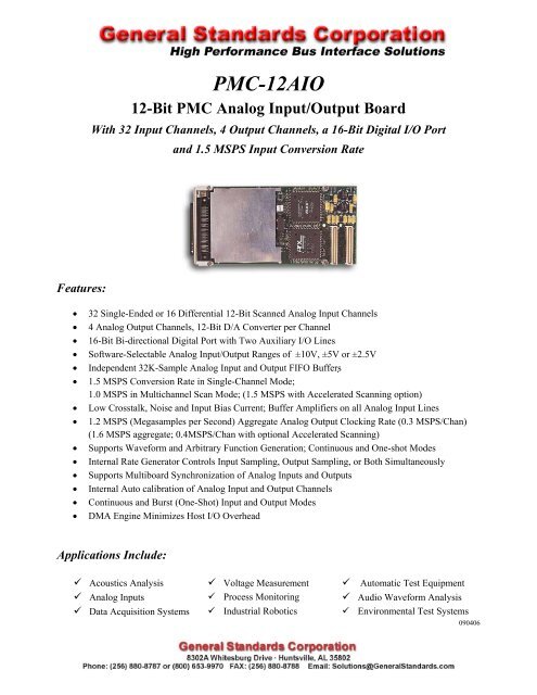
<strong>PMC</strong>-<strong>12</strong>AIO<br />
<strong>12</strong>-<strong>Bit</strong> <strong>PMC</strong> <strong>Analog</strong> <strong><strong>In</strong>put</strong>/<strong><strong>Out</strong>put</strong> Board<br />
With <strong>32</strong> <strong><strong>In</strong>put</strong> Channels, 4 <strong><strong>Out</strong>put</strong> Channels, a 16-<strong>Bit</strong> Digital I/O Port<br />
and 1.5 MSPS <strong><strong>In</strong>put</strong> Conversion Rate<br />
Features:<br />
• <strong>32</strong> Single-Ended or 16 Differential <strong>12</strong>-<strong>Bit</strong> Scanned <strong>Analog</strong> <strong><strong>In</strong>put</strong> Channels<br />
• 4 <strong>Analog</strong> <strong><strong>Out</strong>put</strong> Channels, <strong>12</strong>-<strong>Bit</strong> D/A Converter per Channel<br />
• 16-<strong>Bit</strong> Bi-directional Digital Port with Two Auxiliary I/O Lines<br />
• Software-Selectable <strong>Analog</strong> <strong><strong>In</strong>put</strong>/<strong><strong>Out</strong>put</strong> Ranges of ±10V, ±5V or ±2.5V<br />
• <strong>In</strong>dependent <strong>32</strong>K-Sample <strong>Analog</strong> <strong><strong>In</strong>put</strong> and <strong><strong>Out</strong>put</strong> FIFO Buffers<br />
• 1.5 MSPS Conversion Rate in Single-Channel Mode;<br />
1.0 MSPS in Multichannel Scan Mode; (1.5 MSPS with Accelerated Scanning option)<br />
• Low Crosstalk, Noise and <strong><strong>In</strong>put</strong> Bias Current; Buffer Amplifiers on all <strong>Analog</strong> <strong><strong>In</strong>put</strong> Lines<br />
• 1.2 MSPS (Megasamples per Second) Aggregate <strong>Analog</strong> <strong><strong>Out</strong>put</strong> Clocking Rate (0.3 MSPS/Chan)<br />
(1.6 MSPS aggregate; 0.4MSPS/Chan with optional Accelerated Scanning)<br />
• Supports Waveform and Arbitrary Function Generation; Continuous and One-shot Modes<br />
• <strong>In</strong>ternal Rate Generator Controls <strong><strong>In</strong>put</strong> Sampling, <strong><strong>Out</strong>put</strong> Sampling, or Both Simultaneously<br />
• Supports Multiboard Synchronization of <strong>Analog</strong> <strong><strong>In</strong>put</strong>s and <strong><strong>Out</strong>put</strong>s<br />
• <strong>In</strong>ternal Auto calibration of <strong>Analog</strong> <strong><strong>In</strong>put</strong> and <strong><strong>Out</strong>put</strong> Channels<br />
• Continuous and Burst (One-Shot) <strong><strong>In</strong>put</strong> and <strong><strong>Out</strong>put</strong> Modes<br />
• DMA Engine Minimizes Host I/O Overhead<br />
Applications <strong>In</strong>clude:<br />
Acoustics Analysis Voltage Measurement Automatic Test Equipment<br />
<strong>Analog</strong> <strong><strong>In</strong>put</strong>s Process Monitoring Audio Waveform Analysis<br />
Data Acquisition Systems <strong>In</strong>dustrial Robotics Environmental Test Systems<br />
090406
Functional Description:<br />
The <strong>PMC</strong>-<strong>12</strong>AIO board provides cost effective high-speed <strong>12</strong>-bit analog input/output resources on<br />
a standard single-width <strong>PMC</strong> module. Four analog output channels can be updated either<br />
synchronously or asynchronously, and support waveform generation. <strong>In</strong>ternal autocalibration<br />
networks permit calibration to be performed without removing the board from the system.<br />
Software-controlled test configurations include a loopback mode for monitoring all analog output<br />
channels. Gain and offset correction of the analog input and output channels is performed by<br />
calibration DAC's that are loaded with channel correction values during autocalibration. A digital<br />
I/O port provides 16 bidirectional data lines and two auxiliary I/O lines.<br />
The analog inputs are software-configurable either as <strong>32</strong> single-ended channels or as 16 differential<br />
signal pairs. Buffer amplifiers on all input lines eliminate multiplexer input switching noise, and<br />
minimize crosstalk and input bias currents. <strong>Analog</strong> input data accumulates in a <strong>32</strong>K-sample buffer<br />
until retrieved by the PCI bus. Each of the four analog output channels contains a dedicated <strong>12</strong>-bit<br />
D/A converter and an output range control network. The board receives analog output data from<br />
the PCI bus through a <strong>32</strong>K-sample FIFO buffer.<br />
I/O<br />
Conn<br />
<strong>Analog</strong><br />
<strong><strong>In</strong>put</strong>s<br />
<strong>32</strong> S.E.,<br />
16 Diff<br />
Selftest<br />
Switches<br />
<strong><strong>In</strong>put</strong><br />
Buffer<br />
Amps<br />
<strong>Analog</strong><br />
Mux<br />
Loopback<br />
<strong><strong>In</strong>put</strong><br />
Range<br />
Control<br />
<strong>12</strong>-BIT ADC<br />
Vtest <strong>Out</strong><br />
<strong><strong>In</strong>put</strong><br />
Sync I/O<br />
Voltage<br />
Reference<br />
AI<br />
Buffer<br />
8-<strong>Bit</strong><br />
Calibration<br />
DAC’S I/O<br />
Conn<br />
PCI<br />
Conn<br />
PCI<br />
<strong>In</strong>terface<br />
Adapter<br />
AO<br />
Buffer<br />
Local Bus<br />
Local<br />
Controller<br />
<strong>12</strong>-<strong>Bit</strong><br />
<strong><strong>Out</strong>put</strong><br />
DAC’s<br />
(4)<br />
<strong>Analog</strong><br />
<strong><strong>Out</strong>put</strong>s<br />
4 S.E.<br />
Figure 1. <strong>PMC</strong>-<strong>12</strong>AIO; Functional Organization<br />
This product is functionally compatible with the IEEE PCI local bus specification Revision 2.3, and supports<br />
the "plug-n-play" initialization concept. System input/output connections are made at the panel bracket<br />
through a high-density 68-pin connector. Power requirements consist of +5 VDC, in compliance with the<br />
PCI specification, and operation over the specified temperature range is achieved with conventional<br />
convection cooling.
At +25 O C, with specified operating voltages<br />
ANALOG INPUT CHANNELS<br />
ELECTRICAL SPECIFICATIONS<br />
<strong><strong>In</strong>put</strong> Characteristics:<br />
Configuration:<br />
Voltage Ranges:<br />
<strong><strong>In</strong>put</strong> Impedance:<br />
Bias Current:<br />
Noise:<br />
Common Mode Rejection:<br />
Common Mode Range:<br />
Overvoltage Protection:<br />
<strong>32</strong> input lines, configurable as <strong>32</strong> single-ended or 16 differential channels<br />
Software configurable as ±10, ±5 or ±2.5 Volts<br />
1.0 Megohms line-to-ground, 2.0 Megohms line-to-line, in parallel with 100Pfd.<br />
<strong>In</strong>dependent of scan rate.<br />
80 nanoamps maximum<br />
0.7 LSB-RMS typical<br />
60 dB typical, DC-60 Hz, differential input mode<br />
±10 Volts; differential input configuration<br />
Standard: ±30 Volts with power applied; ±15 Volts with power removed<br />
Transfer Characteristics:<br />
Resolution:<br />
Maximum Conversion Rate:<br />
Channels per scan:<br />
Maximum Scan Rate:<br />
Minimum Scan Rate:<br />
DC Accuracy:<br />
(Maximum composite error,<br />
referred to inputs)<br />
Crosstalk Rejection:<br />
<strong>In</strong>tegral Nonlinearity:<br />
Differential Nonlinearity:<br />
<strong>12</strong> <strong>Bit</strong>s; 0.0244 percent of FSR<br />
1500K conversions per second, minimum in single-channel mode,<br />
1000K in multichannel modes (1500K with 'Accelerated Scanning' factory option).<br />
2, 4, 8, 16, or <strong>32</strong> Channels per scan (<strong>32</strong> channels available only in single-ended mode)<br />
1500K scans/sec in single-channel mode. 31K-500K scans per second in scanning<br />
modes (47K-750K scans per second with Accelerated Scanning option).<br />
Scan rate equals the conversion rate divided by the number of channels per scan.<br />
458 scans per second, using a single internal rate generator; 0.007SPS using both<br />
generators. Zero, using a software sync flag or an externally supplied sync input.<br />
Range Midscale Accuracy ±Fullscale Accuracy<br />
±10V ±4.2mV ±8.4mV<br />
±5V ±3.5mV ±5.2mV<br />
±2.5V ±2.5mV ±4.0mV<br />
75dB, DC-10kHz<br />
±0.024 percent of FSR, maximum<br />
±0.024 percent of FSR, maximum<br />
<strong>Analog</strong> <strong><strong>In</strong>put</strong> Operating Modes and Controls<br />
<strong>Analog</strong> <strong><strong>In</strong>put</strong> Modes: Single Scan: A software or hardware sync initiates a single scan of all active<br />
channels at the maximum conversion rate. As many as three<br />
target boards can be synchronized to a single initiator board.<br />
Continuous Scan: <strong><strong>In</strong>put</strong>s are scanned continuously at the selected scan rate.<br />
Selftest:<br />
Reference and loopback tests; autocalibration
<strong>Analog</strong> <strong><strong>In</strong>put</strong> Modes (Cont.): Multiple-Channel: 2, 4, 8, 16 or <strong>32</strong> channels per scan<br />
<strong><strong>In</strong>put</strong> Data Buffer:<br />
Single-Channel:<br />
Any single-channel can be selected for digitizing at the<br />
maximum conversion rate.<br />
<strong>32</strong>K-sample FIFO with 0000h-7FFEh adjustable threshold flag; DMA is supported<br />
ANALOG OUTPUT CHANNELS<br />
<strong><strong>Out</strong>put</strong> Characteristics:<br />
Configuration:<br />
Voltage Ranges:<br />
<strong><strong>Out</strong>put</strong> Resistance:<br />
<strong><strong>Out</strong>put</strong> protection:<br />
Load Current:<br />
Load Capacitance:<br />
Noise:<br />
Glitch Impulse:<br />
Transfer Characteristics:<br />
Resolution:<br />
<strong><strong>Out</strong>put</strong> Sample Rate:<br />
DC Accuracy:<br />
(Max error, no-load)<br />
Settling Time:<br />
Crosstalk Rejection:<br />
<strong>In</strong>tegral Nonlinearity:<br />
Differential Nonlinearity:<br />
Four single-ended output channels. (Ordering option)<br />
Same as selected for analog inputs; ±10, ±5 or ±2.5 Volts<br />
1.0 Ohm, maximum<br />
Withstands sustained short-circuiting to ground<br />
Zero to ±3ma per channel<br />
Stable with zero to 2000 pF shunt capacitance<br />
2.0mV-RMS, 10Hz-100KHz typical<br />
5 nV-Sec typical, ±2.5V range<br />
<strong>12</strong> <strong>Bit</strong>s (0.0244 percent of FSR)<br />
Software adjustable from 458SPS to 400KSPS per channel with optional accelerated<br />
scanning; 366SPS to 300KSPS standard; 0.007SPS to 400KSPS (300KSPS standard)<br />
using both internal rate generators. DC to 400KSPS (DC-300KSPS standard) with<br />
hardware or software sync.<br />
Range Midscale Accuracy ±Fullscale Accuracy<br />
±10V ±4.0mV ±7.5mV<br />
±5V ±3.1mV ±4.7mV<br />
±2.5V ±2.0mV ±3.5mV<br />
8us to 1LSB, typical with 50-percent fullscale step<br />
65 dB minimum, DC-1000Hz<br />
±0.025 percent of FSR, maximum<br />
±0.015 percent of FSR, maximum<br />
<strong>Analog</strong> <strong><strong>Out</strong>put</strong> Operating Modes and Controls<br />
Clocking Modes:<br />
Simultaneous Continuous Mode: Channel values in a designated channel group are<br />
stored in an intermediate buffer, and then are transferred to the output DAC's when an<br />
output clock occurs. The clock can be generated either by the internal rate generator,<br />
by a software flag, or by an external hardware trigger. As many as three target boards<br />
can be clock-synchronized to a single initiator board.<br />
Simultaneous Burst Mode: A single function (i.e.: burst) is initiated by a software or<br />
hardware sync. During a burst, channel values in a designated channel group are<br />
stored in a transfer buffer, and then are transferred to the output DAC's each time a<br />
clock pulse is generated by the internal rate generator. The burst terminates when a<br />
Burst End flag is encountered.
Clocking Modes (Cont.):<br />
Channel Assignment:<br />
Group End:<br />
Burst End:<br />
<strong><strong>Out</strong>put</strong> Data Buffer:<br />
Channel-Sequential Modes: Same as simultaneous modes, but each value in the data<br />
buffer is written immediately to the associated output DAC. The group-end flag is<br />
ignored in this mode.<br />
A 2-bit field in the output buffer assigns the associated data field to a specific output<br />
channel.<br />
A single bit in the output buffer indicates the last value in a channel group.<br />
A single bit in the output buffer indicates the last value in an output burst sequence.<br />
<strong>32</strong>K-sample FIFO with 0000h-7FFEh adjustable threshold flag; DMA is supported<br />
RATE GENERATORS<br />
<strong>Analog</strong> outputs and inputs can be clocked from either of two independent rate generators, or both inputs and outputs<br />
can be synchronized to a single generator. Each rate generator uses a 16-bit adjustable frequency divider, and the<br />
two generators can be operated in series to provide very low clocking rates.<br />
DIGITAL I/O PORT<br />
The digital I/O port consists of 16 bidirectional data lines, one auxiliary input line and one auxiliary output line. An<br />
interrupt request can be generated in response to the auxiliary input. The data lines are organized as two data bytes,<br />
each of which can be configured independently as either an input or output byte. Standard TTL logic levels apply,<br />
with 20 ma current-sink capability per output line.<br />
PCI INTERFACE<br />
Compatibility:<br />
Conforms to PCI Specification 2.3, with D<strong>32</strong> read/write transactions.<br />
Supports "plug-n-play" initialization.<br />
Provides one multifunction interrupt.<br />
Supports DMA transfers as bus master.<br />
MECHANICAL AND ENVIRONMENTAL SPECIFICATIONS<br />
Power Requirements<br />
+5VDC ±0.2 VDC at 1.3 Amps, maximum<br />
Maximum Power Dissipation: 5.5 Watts, Side 1; 1.0 Watt, Side 2<br />
Physical Characteristics<br />
Height: 13.5 mm (0.53 in)<br />
Depth: 149.0 mm (5.87 in)<br />
Width: 74.0 mm (2.91 in)<br />
Shield: Optional EMI shield available for Side 1.<br />
Environmental Specifications<br />
Ambient Temperature Range:<br />
Relative Humidity:<br />
Altitude:<br />
Cooling:<br />
Operating: 0 to +65 degrees Celsius inlet air<br />
Storage: -40 to +85 degrees Celsius<br />
Operating: 0 to 80%, non-condensing<br />
Storage: 0 to 95%, non-condensing<br />
Operation to 10,000 ft.<br />
Conventional convection cooling.
ORDERING INFORMATION<br />
Specify the basic product model number followed by an option suffix "-ABCD", as indicated below. For example,<br />
model number <strong>PMC</strong>-<strong>12</strong>AIO-41A describes a board with 4 output channels, a bezel and EMI shield, accelerated<br />
scanning, and no custom features.<br />
Optional Parameter Value Specify Option As:<br />
Number of <strong>Analog</strong> <strong><strong>Out</strong>put</strong>s No <strong><strong>Out</strong>put</strong> Channels A = 0<br />
4 <strong><strong>Out</strong>put</strong> Channels A = 4<br />
EMI Shield (Recommended No bezel or shield B = 0<br />
in high-noise environments) Bezel & shield installed B = 1<br />
Accelerated Scanning No acceleration C = N (or Blank)<br />
Accelerated Scanning<br />
Custom Feature --- D *<br />
C = A<br />
* Numeric code, determined by specific feature. Blank or zero (0) if no custom feature applies.<br />
SYSTEM I/O CONNECTIONS<br />
Table 1. System Connector Pin Functions<br />
P5 ROW-A<br />
P5 ROW-B<br />
PIN SIGNAL PIN SIGNAL<br />
34 ANA INP00 HI 34 ANA OUT00<br />
33 ANA INP00 LO * 33 OUTPUT RTN<br />
<strong>32</strong> ANA INP02 HI <strong>32</strong> ANA OUT01<br />
31 ANA INP02 LO 31 OUTPUT RTN<br />
30 ANA INP04 HI 30 ANA OUT02<br />
29 ANA INP04 LO 29 OUTPUT RTN<br />
28 ANA INP06 HI 28 ANA OUT03<br />
27 ANA INP06 LO 27 OUTPUT RTN<br />
26 ANA INP08 HI 26 VTEST<br />
25 ANA INP08 LO 25 VTEST RTN<br />
24 ANA INP10 HI 24 DIGITAL RTN<br />
23 ANA INP10 LO 23 AUX DIGITAL IN<br />
22 ANA INP<strong>12</strong> HI 22 AUX DIGITAL OUT<br />
21 ANA INP<strong>12</strong> LO 21 DIG IO 00<br />
20 ANA INP14 HI 20 DIG IO 01<br />
19 ANA INP14 LO 19 DIG IO 02<br />
18 INPUT RTN 18 DIG IO 03<br />
17 INPUT RTN 17 DIG IO 04<br />
16 ANA INP16 HI 16 DIG IO 05<br />
15 ANA INP16 LO 15 DIG IO 06<br />
14 ANA INP18 HI 14 DIG IO 07<br />
13 ANA INP18 LO 13 DIG IO 08<br />
<strong>12</strong> ANA INP20 HI <strong>12</strong> DIG IO 09<br />
11 ANA INP20 LO 11 DIG IO 10<br />
10 ANA INP22 HI 10 DIG IO 11<br />
9 ANA INP22 LO 9 DIG IO <strong>12</strong><br />
8 ANA INP24 HI 8 DIG IO 13<br />
7 ANA INP24 LO 7 DIG IO 14<br />
6 ANA INP26 HI 6 DIG IO 15<br />
5 ANA INP26 LO 5 DIGITAL RTN<br />
4 ANA INP28 HI 4 SYNC OUTPUT<br />
3 ANA INP28 LO 3 DIGITAL RTN<br />
2 ANA INP30 HI 2 SYNC INPUT<br />
1 ANA INP30 LO 1 DIGITAL RTN<br />
ROW B<br />
P5<br />
CONN<br />
PWB<br />
Panel Pin-view<br />
ROW A<br />
PIN 34<br />
PIN 1<br />
Figure 2. System <strong><strong>In</strong>put</strong>/<strong><strong>Out</strong>put</strong> Connector<br />
System Mating Connector:<br />
68-Pin 2-row 0.050" dual-ribbon cable<br />
socket connector: Robinson Nugent<br />
#P50E-068-S-TG, or equivalent.<br />
Contact factory for availability of the<br />
68-pin AMP SCSI-3 connector.<br />
* <strong>Analog</strong> inputs are shown for the differential input mode. <strong>In</strong> singleended<br />
mode, LO inputs become consecutive odd-numbered<br />
channels, beginning with ANA INP 01 replacing ANA INP 00 LO.<br />
General Standards Corp.<br />
General Standards Corporation assumes no responsibility for the use of any circuits in this product. No circuit patent licenses are implied. <strong>In</strong>formation included herein<br />
supersedes previously published specifications on this product and is subject to change without notice.