the removal of colour from synthetic textile dye effluent - Garph.co.uk
the removal of colour from synthetic textile dye effluent - Garph.co.uk
the removal of colour from synthetic textile dye effluent - Garph.co.uk

You also want an ePaper? Increase the reach of your titles
YUMPU automatically turns print PDFs into web optimized ePapers that Google loves.
International Journal <strong>of</strong> Advanced Research in<br />
IT and Engineering ISSN: 2278-6244<br />
THE REMOVAL OF COLOUR FROM SYNTHETIC TEXTILE DYE EFFLUENT USING<br />
M.Sathiyamoorthy*<br />
Mingizem Gashaw*<br />
Melakuu Tesfaye*<br />
Mulugeta Yilma*<br />
Tigist Tasew*<br />
Netsanet Fantahun*<br />
CELLULOSE ACETATE REVERSE OSMOSIS MEMBRANE<br />
Abstract: The main objective <strong>of</strong> this work is to remove <strong>the</strong> <strong><strong>co</strong>lour</strong> <strong>from</strong> syn<strong>the</strong>tic <strong>textile</strong> <strong>dye</strong><br />
<strong>effluent</strong> by membrane technology. The delivery <strong>of</strong> <strong><strong>co</strong>lour</strong> in <strong>the</strong> form <strong>of</strong> <strong>dye</strong>s onto <strong>textile</strong><br />
fibres is not an efficient process. The degree <strong>of</strong> efficiency varies, depending on <strong>the</strong> method <strong>of</strong><br />
delivery. As a result, most <strong>of</strong> <strong>the</strong> wastewater produced by <strong>the</strong> <strong>textile</strong> industry is <strong><strong>co</strong>lour</strong>ed. It is<br />
likely that <strong><strong>co</strong>lour</strong>ed wastewater was a feature <strong>of</strong> <strong>the</strong> first practices <strong>of</strong> <strong>textile</strong> <strong>dye</strong>ing. To make<br />
this research effective we suggest reverse osmosis process. The membrane used for reverse<br />
osmosis is cellulose acetate membrane and gravitational force is used as a major driving<br />
force. Many <strong>of</strong> <strong>the</strong> systems <strong>of</strong> separation use pressure gradient as <strong>the</strong> main driving force, but<br />
here we are keeping gravitational force as <strong>the</strong> main driving force with less amount <strong>of</strong> inlet<br />
pressure. The two syn<strong>the</strong>tic <strong>dye</strong>s which are <strong>co</strong>mmonly present in <strong>the</strong> <strong>effluent</strong> <strong>of</strong> <strong>textile</strong> waste<br />
water were <strong>co</strong>nsidered, namely Torquise blue <strong>dye</strong> and Remozol yellow <strong>dye</strong>. Then <strong>the</strong>se two<br />
different types <strong>of</strong> <strong>dye</strong>s solution are treated in <strong>the</strong> reverse osmosis <strong>co</strong>lumn which <strong>co</strong>ntains<br />
cellulose acetate membrane to check <strong>the</strong> percentage <strong>of</strong> <strong>co</strong>lor <strong>removal</strong>. This four stage setup<br />
is very much effective for <strong>effluent</strong> treatment also. This research work focused on <strong>the</strong> reverse<br />
osmosis part only for <strong>the</strong> <strong><strong>co</strong>lour</strong> <strong>removal</strong> <strong>of</strong> <strong>the</strong> syn<strong>the</strong>tic <strong>effluent</strong>. The result shows that it is<br />
very much effective for <strong>the</strong> <strong><strong>co</strong>lour</strong> <strong>removal</strong>.<br />
Keywords: Colour <strong>removal</strong>, Textile <strong>dye</strong> <strong>effluent</strong>, Reverse osmosis, Membrane, Cellulose<br />
acetate, Dyes, Effluent treatment.<br />
*Department <strong>of</strong> Chemical Engineering, School <strong>of</strong> Engineering & Information Technologies,<br />
Adama Science & Technology University, Adama, Ethiopia, Africa.<br />
Vol. 1 | No.4 | October 2012 www.garph.<strong>co</strong>.<strong>uk</strong> IJARIE | 25
International Journal <strong>of</strong> Advanced Research in<br />
IT and Engineering ISSN: 2278-6244<br />
1. INTRODUCTION<br />
1.1. Reverse Osmosis (RO) process<br />
Reverse Osmosis, initially termed as hyper filtration, is ano<strong>the</strong>r pressure driven process in<br />
which a solvent or a predominating <strong>co</strong>mponent <strong>of</strong> <strong>the</strong> solution is transferred through a<br />
membrane in such a way that <strong>the</strong> <strong>co</strong>ncentration <strong>of</strong> <strong>the</strong> solution is transferred through a<br />
membrane in such a way that <strong>the</strong> <strong>co</strong>ncentration <strong>of</strong> some solute with low molecular weights<br />
(up to 500 Daltons) or o<strong>the</strong>r solvents is decreased. This process applies for <strong>removal</strong> <strong>of</strong><br />
particles sizes <strong>of</strong> 5 × 10 -3 &<br />
5 × 10 -4 µm. The reverse osmosis or hyper filtration, which is<br />
characterized by a membrane pore size in <strong>the</strong> range <strong>of</strong> 0.0005 microns. Some researchers<br />
<strong>co</strong>nsider <strong>the</strong> RO membrane as with out have pores. Transport <strong>of</strong> <strong>the</strong> solvent is ac<strong>co</strong>mplished<br />
through <strong>the</strong> free volume between <strong>the</strong> segments <strong>of</strong> <strong>the</strong> polymer <strong>of</strong> which <strong>the</strong> membrane is<br />
<strong>co</strong>nstituted. The operating pressures in RO are generally between 7 and 100 bar and this<br />
technique is mainly used to remove water. The importance <strong>of</strong> <strong>the</strong>se membrane processes<br />
can be judged <strong>from</strong> <strong>the</strong> membrane area installed in <strong>the</strong> various industrial sectors.<br />
Membrane applications can be seen in below table:<br />
Process<br />
Micro filtration<br />
Ultra filtration<br />
Nano filtration<br />
Reverse osmosis<br />
Electro dialysis<br />
Gas permeation<br />
Pervaporation<br />
Applications<br />
Sterile solution, water purification, beverage filtration<br />
<strong>effluent</strong>s.<br />
Protein <strong>co</strong>ncentration (enzyme), oily wastewaters <strong>effluent</strong>,<br />
blood fractionation, antibiotic separation.<br />
Potable water, desalination <strong>of</strong> brackish water, polyvalent<br />
ions stream cleaning, whey fractionation.<br />
Food <strong>co</strong>ncentration, water purification, desalination<br />
(monovalent ions stream), biomedical application.<br />
Desalination, water purification, deacidification <strong>of</strong> citrus<br />
juice.<br />
Separation <strong>of</strong> He <strong>from</strong> natural gas, He re<strong>co</strong>very, CO 2 <strong>removal</strong>,<br />
NG dehydration<br />
Dehydration <strong>of</strong> organic solvents<br />
Vol. 1 | No.4 | October 2012 www.garph.<strong>co</strong>.<strong>uk</strong> IJARIE | 26
International Journal <strong>of</strong> Advanced Research in<br />
IT and Engineering ISSN: 2278-6244<br />
1.2. Types <strong>of</strong> membranes<br />
Table 1: Typical membrane applications<br />
The different types <strong>of</strong> Polymers used for membrane manufacturing includes:<br />
<br />
<br />
<br />
<br />
<br />
<br />
Cellulose Acetate (CA) and Blends with di - and tri – Acetates<br />
Polyamide (PA)<br />
Polysulfone (PS)<br />
Sulfonated Polysulfone (SPS)<br />
Thin film <strong>co</strong>mposite and<br />
Hydrophilic and Hydrophobic PTFE membrane.<br />
The above membranes differ in <strong>the</strong>ir properties such as surface pore size, pore distribution,<br />
rejection, flux, temperature stability, solvent resistance and pressure resistance. The choice<br />
<strong>of</strong> membranes for a particular application <strong>co</strong>nstitutes <strong>the</strong> most important step toward its<br />
process development. The factors affecting retentivity <strong>of</strong> any membrane include size and<br />
shape <strong>of</strong> molecules, presence <strong>of</strong> o<strong>the</strong>r solutes, type <strong>of</strong> membrane material, membrane<br />
<strong>co</strong>nfiguration, and <strong>co</strong>ncentration <strong>of</strong> retained species and adsorption <strong>of</strong> solute into <strong>the</strong><br />
membrane.<br />
1.3. Configurations <strong>of</strong> membrane modules<br />
Membranes are used in specific <strong>co</strong>nfigurations to optimize design criteria like a high<br />
membrane surface to volume ratio, low pressure drop on <strong>the</strong> feed side, turbulent flow on<br />
<strong>the</strong> feed side, ease <strong>of</strong> membrane cleaning, long membrane life and low replacement <strong>co</strong>st.<br />
The most <strong>co</strong>mmon <strong>co</strong>nfigurations available <strong>co</strong>mmercially are:<br />
<br />
<br />
<br />
<br />
Spiral Wound<br />
Tubular<br />
Hollow fiber &<br />
Plate and Frame<br />
Industrial scale membrane systems are usually <strong>co</strong>nstructed with multiple modules to<br />
increase performance in terms <strong>of</strong> re<strong>co</strong>very, capacity, etc. Important multiple modular<br />
arrangements are as follows:<br />
<br />
<br />
<br />
Parallel mode<br />
Series mode<br />
Tapered mode<br />
Vol. 1 | No.4 | October 2012 www.garph.<strong>co</strong>.<strong>uk</strong> IJARIE | 27
1.4. Dyes<br />
International Journal <strong>of</strong> Advanced Research in<br />
IT and Engineering ISSN: 2278-6244<br />
Recycle mode<br />
There are more than 100,000 <strong>co</strong>mmercially available <strong>dye</strong>s with over million tones <strong>of</strong><br />
<strong>dye</strong>stuff produced annually. Due to <strong>the</strong>ir chemical structure, <strong>dye</strong>s are resistant to fading on<br />
exposure to light, water, and many chemicals. Also many <strong>dye</strong>s are difficult to be de<strong>co</strong>lorized<br />
and de<strong>co</strong>mposed biologically. There are many structure varieties such as acidic, basic,<br />
disperse, azo, diazo, anthroquinone based, and metal <strong>co</strong>mplex <strong>dye</strong>s. These <strong>dye</strong>s are very<br />
stable and can be de<strong>co</strong>mposed only at temperatures higher than 200 0 C. For this reason<br />
syn<strong>the</strong>tic <strong>dye</strong>s <strong>of</strong>ten receive <strong>co</strong>nsiderable attention <strong>from</strong> researchers in <strong>textile</strong> waste water<br />
treatment processes.<br />
1.5. Methods <strong>of</strong> treating <strong>dye</strong> <strong>co</strong>ntaining wastewater<br />
Dye released to <strong>the</strong> waste stream, if without proper treatment, <strong>co</strong>uld exert great impact to<br />
<strong>the</strong> environment. Many <strong>textile</strong> manufacturers use <strong>dye</strong>s that release aromatic amines (eg.,<br />
benzidine, toluidine). Dye bath <strong>effluent</strong>s may <strong>co</strong>ntain heavy metals, ammonia, alkali salts,<br />
toxic solids and large amounts <strong>of</strong> pigments, many <strong>of</strong> which are toxic. About 40 percent <strong>of</strong><br />
globally used <strong>co</strong>lorants <strong>co</strong>ntain organically bound chlorine, a known carcinogen. Natural<br />
<strong>dye</strong>s are rarely low impact, depending on <strong>the</strong> specific <strong>dye</strong> and mordant used. Mordents (<strong>the</strong><br />
substance used to "fix" <strong>the</strong> <strong>co</strong>lor onto <strong>the</strong> fabric) such as chromium are very toxic and has a<br />
high impact. Hence, to protecting <strong>the</strong> environment and to meet <strong>the</strong> stringent government<br />
laws, many researchers try to find an effective and e<strong>co</strong>nomical way <strong>of</strong> treating <strong>dye</strong><br />
<strong>co</strong>ntaining wastewater. Several studies have been performed, that can be classified into on<br />
three categories depending on <strong>the</strong> method used. They are chemical, physical, and biological<br />
methods. Currently, <strong>the</strong> main methods <strong>of</strong> <strong>textile</strong> <strong>dye</strong>-<strong>co</strong>ntaining wastewater treatment are<br />
physical and chemical methods.<br />
2. LITERATURE REVIEW<br />
The <strong>co</strong>mmon <strong>dye</strong>s are difficult to be degraded biologically; many researchers were<br />
interested in treatment <strong>of</strong> <strong>dye</strong>-<strong>co</strong>ntaining wastewater. The studies were <strong>co</strong>nducted on<br />
various kinds <strong>of</strong> <strong>dye</strong> wastewater using <strong>the</strong> biological process by Ahmad et al. They found<br />
that COD and <strong>the</strong> <strong>co</strong>lor <strong>of</strong> <strong>dye</strong> wastewater <strong>co</strong>uld not be efficiently removed.<br />
The objective <strong>of</strong> this research [7] is to investigate <strong>the</strong> performance <strong>of</strong> blend cellulose acetate<br />
(CA)-polye<strong>the</strong>rsulphone (PES) membranes prepared using microwave heating (MWH)<br />
Vol. 1 | No.4 | October 2012 www.garph.<strong>co</strong>.<strong>uk</strong> IJARIE | 28
International Journal <strong>of</strong> Advanced Research in<br />
IT and Engineering ISSN: 2278-6244<br />
techniques and <strong>the</strong>n <strong>co</strong>mpare it with blend CA-PES membranes prepared using <strong>co</strong>nventional<br />
heating (CH) methods using bovine serum albumin solution. The superior membranes were<br />
<strong>the</strong>n used in <strong>the</strong> treatment <strong>of</strong> palm oil mill <strong>effluent</strong> (POME). Various blends <strong>of</strong> CA-PES have<br />
been blended with PES in <strong>the</strong> range <strong>of</strong> 1-5 wt%. This distinctive series <strong>of</strong> dope formulations<br />
<strong>of</strong> blend CA/PES and pure CA was prepared using N, N-dimethylformamide (DMF) as solvent.<br />
The dope solution was prepared by MW heating for 5 min at a high pulse and <strong>the</strong><br />
membranes were prepared by phase inversion method. The performances <strong>of</strong> <strong>the</strong>se<br />
membranes were evaluated in terms <strong>of</strong> pure water and permeate flux, percentage <strong>removal</strong><br />
<strong>of</strong> total suspended solids (TSS), chemical oxygen demand (COD) and biochemical oxygen<br />
demand (BOD). The results indicate that blend membranes prepared using <strong>the</strong> microwave<br />
technique is far more superior <strong>co</strong>mpared to that prepared using CH. Blend membranes with<br />
19% CA, 1-3% PES and 80% <strong>of</strong> DMF solvent were found to be <strong>the</strong> best membrane<br />
formulation.<br />
In chromium tanning process, about 20–40% <strong>of</strong> applied chromium is usually discharged into<br />
sewerage system causing serious environmental impact. The spent chromium <strong>effluent</strong>s<br />
<strong>co</strong>llected <strong>from</strong> two local small-size tanneries indicated that chromium <strong>co</strong>ncentration ranged<br />
<strong>from</strong> 1300–2500 mg Cr 6+ /l, while NaCl <strong>co</strong>ncentration varies <strong>from</strong> 40000 to 50000 mg/l. The<br />
study [5] <strong>of</strong> chromium <strong>removal</strong> efficiency by using <strong>of</strong> a pilot-scale setup <strong>of</strong> 7 and 16 bar RO<br />
membrane units at different working pressures and under variable salt <strong>co</strong>ncentrations were<br />
carried out to remove <strong>the</strong> hazardous chromium <strong>from</strong> <strong>the</strong> spent tanning <strong>effluent</strong> and re<strong>co</strong>ver<br />
it for fur<strong>the</strong>r recycling. The study proved that <strong>the</strong> membrane technique is able to separate<br />
chromium efficiently <strong>from</strong> <strong>the</strong> pretreated tanning wastewater. The low <strong>co</strong>st RO membrane<br />
units, i.e. <strong>the</strong> medium and low pressure, <strong>co</strong>uld be used e<strong>co</strong>nomically for separation and<br />
re<strong>co</strong>very <strong>of</strong> chromium <strong>from</strong> wastewater <strong>of</strong> small-size tanning shops.<br />
The delivery <strong>of</strong> <strong><strong>co</strong>lour</strong> in <strong>the</strong> form <strong>of</strong> <strong>dye</strong>s onto <strong>textile</strong> fibres is not an efficient process. The<br />
degree <strong>of</strong> efficiency varies, depending on <strong>the</strong> method <strong>of</strong> delivery. As a result, most <strong>of</strong> <strong>the</strong><br />
wastewater produced by <strong>the</strong> <strong>textile</strong> industry is <strong><strong>co</strong>lour</strong>ed. It is likely that <strong><strong>co</strong>lour</strong>ed<br />
wastewater was a feature <strong>of</strong> <strong>the</strong> first practices <strong>of</strong> <strong>textile</strong> <strong>dye</strong>ing. However, treatment to<br />
remove this <strong><strong>co</strong>lour</strong> was not <strong>co</strong>nsidered until <strong>the</strong> early natural <strong>dye</strong>stuffs were replaced by<br />
syn<strong>the</strong>tic <strong>dye</strong>s, and <strong>the</strong> persistence <strong>of</strong> such syn<strong>the</strong>tic <strong>dye</strong>s in <strong>the</strong> environment was<br />
re<strong>co</strong>gnized. Colour pollution in aquatic environments is an escalating problem, despite <strong>the</strong><br />
Vol. 1 | No.4 | October 2012 www.garph.<strong>co</strong>.<strong>uk</strong> IJARIE | 29
International Journal <strong>of</strong> Advanced Research in<br />
IT and Engineering ISSN: 2278-6244<br />
fact that <strong>the</strong>re has been substantial research into <strong>the</strong> modification <strong>of</strong> <strong>the</strong> <strong>dye</strong>ing process to<br />
improve <strong>the</strong> level <strong>of</strong> affinity/fixation <strong>of</strong> <strong>the</strong> <strong>dye</strong>stuffs onto <strong>the</strong> substrate. The recalcitrant<br />
nature <strong>of</strong> modern syn<strong>the</strong>tic <strong>dye</strong>s has led to <strong>the</strong> imposition <strong>of</strong> strict environmental<br />
regulations. The need for a <strong>co</strong>st effective process to remove <strong>the</strong> <strong><strong>co</strong>lour</strong> <strong>from</strong> wastewater<br />
produced by <strong>the</strong> <strong>textile</strong> industry has been re<strong>co</strong>gnized. Several strategies have been<br />
investigated [13] . However, <strong>the</strong> review presented here <strong>co</strong>ncerns <strong>the</strong> use <strong>of</strong> whole bacterial<br />
cells for <strong>the</strong> reduction <strong>of</strong> water-soluble <strong>dye</strong>s present in <strong>textile</strong> <strong>dye</strong>ing wastewater.<br />
A modified micr<strong>of</strong>iltration membrane has been prepared by blending a matrix polymer with<br />
a functional polymer. Cellulose acetate (CA) was blended with polyethyleneimine (PEI),<br />
which was <strong>the</strong>n crosslinked by polyisocyanate, in a mixture <strong>of</strong> solvents. In <strong>the</strong> membrane,<br />
PEI can supply <strong>co</strong>upling sites for ligands in affinity separation or be used as ligands for metal<br />
chelating, <strong>removal</strong> <strong>of</strong> endotoxin or ion exchange. The effects <strong>of</strong> <strong>the</strong> time <strong>of</strong> phase inversion<br />
induced by water vapor, blended amount <strong>of</strong> PEI and amount <strong>of</strong> cross linking agent on<br />
membrane performance were investigated [22] . The prepared blend membranes have<br />
specific surface area <strong>of</strong> 12.04 – 24.11 m 2 /g and pure water flux (PWF) <strong>of</strong> 10–50 ml/cm 2 min<br />
with porosity <strong>of</strong> 63–75%. The membranes, made <strong>of</strong> 0.1550 wt% PEI/CA ratio and 0.5<br />
cross linking agent/PEI ratio, were applied to adsorbing Cu 2+ and bovine serum albumin<br />
(BSA) individually. The maximum adsorption capacity <strong>of</strong> Cu ion on <strong>the</strong> blend membrane is<br />
7.42 mg/g dry membrane. The maximum adsorption capacities <strong>of</strong> BSA on <strong>the</strong> membranes<br />
with and without chelating Cu ion are 86.6 and 43.8 mg/g dry membrane, respectively.<br />
3. PROCESS DESCRIPTION<br />
Osmosis is a natural phenomenon in which a solvent (usually water) passes through a semi<br />
permeable barrier <strong>from</strong> <strong>the</strong> side with lower solute <strong>co</strong>ncentration to <strong>the</strong> higher solute<br />
<strong>co</strong>ncentration side. Water flow <strong>co</strong>ntinues until chemical potential equilibrium <strong>of</strong> <strong>the</strong> solvent<br />
is established. At equilibrium, <strong>the</strong> pressure difference between <strong>the</strong> two sides <strong>of</strong> <strong>the</strong><br />
membrane is equal to <strong>the</strong> osmotic pressure <strong>of</strong> <strong>the</strong> solution. To reverse <strong>the</strong> flow <strong>of</strong> water<br />
(solvent), a pressure difference greater than <strong>the</strong> osmotic pressure difference is applied; as a<br />
result, separation <strong>of</strong> water <strong>from</strong> <strong>the</strong> solution occurs as pure water flows <strong>from</strong> <strong>the</strong> high<br />
<strong>co</strong>ncentration side to <strong>the</strong> low <strong>co</strong>ncentration side. This phenomenon is termed reverse<br />
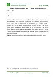
osmosis. The phenomenon <strong>of</strong> reverse osmosis is illustrated in figure. A semi-permeable<br />
membrane is placed between two <strong>co</strong>mpartments. In this <strong>co</strong>nfiguration, <strong>the</strong> direction <strong>of</strong><br />
Vol. 1 | No.4 | October 2012 www.garph.<strong>co</strong>.<strong>uk</strong> IJARIE | 30
International Journal <strong>of</strong> Advanced Research in<br />
IT and Engineering ISSN: 2278-6244<br />
solvent flow is determined by its chemical potential, which is a function <strong>of</strong> pressure,<br />
temperature and <strong>co</strong>ncentration <strong>of</strong> dissolved solids. Pure water in <strong>co</strong>ntact with both sides <strong>of</strong><br />
an ideal semi-permeable membrane at equal pressure and temperature has no net flow<br />
across <strong>the</strong> membrane because <strong>the</strong> chemical potential is equal on both sides.<br />
Figure 1: Schematic representation <strong>of</strong> Reverse Osmosis<br />
Application <strong>of</strong> an external high pressure to <strong>the</strong> salt solution side will raise <strong>the</strong> chemical<br />
potential <strong>of</strong> <strong>the</strong> water in <strong>the</strong> salt solution and cause a solvent flow to <strong>the</strong> pure water side.<br />
These RO systems mainly remove a variety <strong>of</strong> ions and metals as well as certain organic,<br />
inorganic and bacterial <strong>co</strong>ntaminants by using pressure difference as a driving force.<br />
Reverse osmosis has always been noted for its low energy <strong>co</strong>nsumption. The principal uses<br />
<strong>of</strong> reverse osmosis are for <strong>the</strong> reduction <strong>of</strong> high levels <strong>of</strong> nitrate, sulfate, sodium and total<br />
dissolved solids. But a good pre-treatment is necessary for a reverse osmosis system and<br />
<strong>the</strong>re is a possibility <strong>of</strong> a bacterial <strong>co</strong>ntamination.<br />
3.1. Common uses <strong>of</strong> RO process<br />
Reverse Osmosis is a technology that is found virtually anywhere pure water is needed;<br />
<strong>co</strong>mmon uses include:<br />
Drinking Water<br />
Humidification<br />
Ice-Making<br />
Car Wash Water Reclamation<br />
Rinse Waters and<br />
Water used in chemical processes Biomedical, Laboratory & Pharmaceutical<br />
Applications<br />
3.2. Cellulose acetate membrane<br />
Vol. 1 | No.4 | October 2012 www.garph.<strong>co</strong>.<strong>uk</strong> IJARIE | 31
International Journal <strong>of</strong> Advanced Research in<br />
IT and Engineering ISSN: 2278-6244<br />
Cellulose acetate (CA) membranes were <strong>the</strong> first <strong>co</strong>mmercialized RO membranes developed<br />
in <strong>the</strong> late 1960's. CA membranes <strong>of</strong>fered a good <strong>co</strong>mbination <strong>of</strong> rejection, fouling<br />
resistance, and <strong>the</strong> ability to tolerate <strong>co</strong>ntinuous chlorine up to 1.0 ppm. Some <strong>of</strong> <strong>the</strong><br />
reasons <strong>the</strong>y lost favor to <strong>the</strong> new polyamide membranes was <strong>the</strong> requirement for<br />
acidification (CA membranes should be operated at a pH <strong>of</strong> between 4-6 to minimize<br />
hydrolysis), lower rejection (98% versus 99.5%) and higher net drive pressure requirements<br />
(300 psi/20 bar versus 150 psi/10 bar). But in many applications, CA membranes operate<br />
very well and give long and useful service lives. They have an advantage over <strong>the</strong> newer<br />
polyamide membranes for applications with high organic fouling, such as wastewaters, and<br />
waters where biological growth is an issue (easily addressed using chlorine). The <strong>co</strong>mmercial<br />
membrane elements are available in 2.5", 4", 8", 8.3", and 8.5" diameters. There are three<br />
different membranes <strong>of</strong>fered, <strong>the</strong> SB20, SB50, and SB90. The SB20 <strong>of</strong>fers <strong>the</strong> highest<br />
rejection at 98%, while <strong>the</strong> SB50 <strong>of</strong>fers 20% higher flow at 95% salt rejection. The SB90 is a<br />
nan<strong>of</strong>iltration (NF) membrane operating at about twice <strong>the</strong> flow <strong>of</strong> <strong>the</strong> SB20 at 85-90%<br />
rejection.<br />
3.3. Structure <strong>of</strong> cellulose acetate<br />
Cellulose Acetate, syn<strong>the</strong>tic <strong>co</strong>mpound derived <strong>from</strong> <strong>the</strong> acetylation <strong>of</strong> <strong>the</strong> plant substance<br />
cellulose. Cellulose acetate is spun into <strong>textile</strong> fibers known variously as<br />
acetate rayon, acetate, or triacetate. It can also be molded into solid plastic parts such as<br />
tool handles or cast into film for photography or food wrapping, though its use in <strong>the</strong>se<br />
applications has diminished. Cellulose is a naturally occurring polymer obtained <strong>from</strong> wood<br />
fibers or <strong>the</strong> short fibers (linters) adhering to <strong>co</strong>tton seeds. It is made up <strong>of</strong><br />
repeating glu<strong>co</strong>se units that have <strong>the</strong> chemical formula C 6 H 7 O 2 (OH) 3 and <strong>the</strong> following<br />
molecular structure:<br />
Vol. 1 | No.4 | October 2012 www.garph.<strong>co</strong>.<strong>uk</strong> IJARIE | 32
International Journal <strong>of</strong> Advanced Research in<br />
IT and Engineering ISSN: 2278-6244<br />
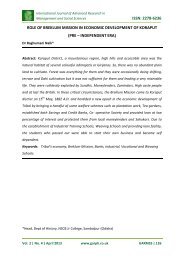
Figure 2: Structure <strong>of</strong> Cellulose acetate.<br />
In unaltered cellulose, <strong>the</strong> X in <strong>the</strong> molecular structure represents hydrogen (H), indicating<br />
<strong>the</strong> presence in <strong>the</strong> molecule <strong>of</strong> three hydroxyl (OH) groups. The OH groups form<br />
strong hydrogen bonds between cellulose molecules, with <strong>the</strong> result that cellulose<br />
structures cannot be loosened by heat or solvents without causing chemical de<strong>co</strong>mposition.<br />
However, upon acetylation, <strong>the</strong> hydrogen in <strong>the</strong> hydroxyl groups is replaced by acetyl<br />
groups (CH 3 -CO). The resultant cellulose acetate <strong>co</strong>mpound can be dissolved in certain<br />
solvents or s<strong>of</strong>tened or melted under heat, allowing <strong>the</strong> material to be spun into fibers,<br />
molded into solid objects, or cast as a film. Cellulose acetate is most <strong>co</strong>mmonly prepared by<br />
treating cellulose with acetic acid and <strong>the</strong>n with acetic anhydride in <strong>the</strong> presence <strong>of</strong> a<br />
catalyst such as sulfuric acid. When <strong>the</strong> resultant reactions are allowed to proceed to<br />
<strong>co</strong>mpletion, <strong>the</strong> product is a fully acetylated <strong>co</strong>mpound known as primary cellulose acetate,<br />
or, more properly, cellulose triacetate. Triacetate is a high melting (300 0 C), highly crystalline<br />
substance that is soluble only in a limited range <strong>of</strong> solvents (usually methylene chloride).<br />
From solution, triacetate can be dry spun into fibers or, with <strong>the</strong> aid <strong>of</strong> plasticizers, cast as a<br />
film. If <strong>the</strong> primary acetate is treated with water, a hydrolization reaction can occur in which<br />
<strong>the</strong> acetylation reaction is partially reversed, producing a se<strong>co</strong>ndary cellulose acetate,<br />
or cellulose diacetate. Diacetate can be dissolved by cheaper solvents such as acetone for<br />
dry spinning into fibers. With a lower melting temperature (230 0 C) than triacetate, diacetate<br />
in flake form can be mixed with appropriate plasticizers into powders for molding solid<br />
objects, and it can also be cast as a film.<br />
3.4. Properties <strong>of</strong> cellulose acetate membranes<br />
Hydrophobic membrane is ideal for use in venting applications.<br />
Vol. 1 | No.4 | October 2012 www.garph.<strong>co</strong>.<strong>uk</strong> IJARIE | 33
International Journal <strong>of</strong> Advanced Research in<br />
IT and Engineering ISSN: 2278-6244<br />
Resists water while simultaneously venting gases.<br />
‘Hydrophobic’ means ‘fear for water’. Hence <strong>the</strong> water does not wet <strong>the</strong> membrane<br />
surface. Strong and durable for easy handling.<br />
Lot-to-lot <strong>co</strong>nsistency with quality checks which ensure lot-to-lot <strong>co</strong>nsistency, both<br />
down and across <strong>the</strong> polyester web, for dependable results every time.<br />
Hydrophobic membrane is a pure polymer internally supported with an inert<br />
polyester web.<br />
3.5. Experimental procedure<br />
The actual project deals with <strong>the</strong> treatment <strong>of</strong> sea water to get <strong>the</strong> drinking water and<br />
treatment <strong>of</strong> <strong>effluent</strong> water <strong>from</strong> <strong>textile</strong> industries to remove <strong>the</strong> <strong>dye</strong>s. For this <strong>the</strong> pH, total<br />
hardness, chemical oxygen demand and biological oxygen demand are <strong>the</strong> parameters<br />
should be measured to prove that water is suitable for drinking.<br />
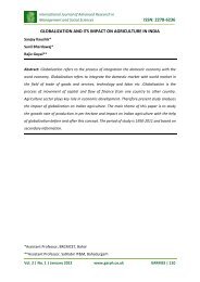
In <strong>the</strong> series <strong>of</strong> steps involved in <strong>the</strong> sea water treatment, we focus our research to <strong>the</strong><br />
reverse osmosis process. For that purpose <strong>the</strong> syn<strong>the</strong>tic <strong>effluent</strong> is treated in <strong>the</strong> <strong>co</strong>lumn<br />
which <strong>co</strong>ntains cellulose acetate membrane. Reverse osmosis is a liquid filtration method<br />
which removes many types <strong>of</strong> large atomic molecules <strong>from</strong> smaller molecules, by forcing <strong>the</strong><br />
liquid at high pressure through a semi permeable membrane with pores (holes) just big<br />
enough to allow <strong>the</strong> small molecules to pass through. The semi permeable membrane in<br />
different stages used here is cellulose acetate.<br />
Figure 3: The reverse osmosis <strong>co</strong>lumn<br />
Vol. 1 | No.4 | October 2012 www.garph.<strong>co</strong>.<strong>uk</strong> IJARIE | 34
International Journal <strong>of</strong> Advanced Research in<br />
IT and Engineering ISSN: 2278-6244<br />
The <strong>effluent</strong> samples (Dye samples) taken for this process are<br />
1. Torquise blue <strong>dye</strong> solution - Sample A<br />
2. Remozol golden yellow <strong>dye</strong> solution - Sample B<br />
These <strong>dye</strong>s are normally present in <strong>the</strong> <strong>textile</strong> <strong>effluent</strong>. Colourimeter is <strong>co</strong>ncerned with <strong>the</strong><br />
determination <strong>of</strong> <strong>co</strong>ncentration <strong>of</strong> substance by measurement <strong>of</strong> <strong>the</strong> relative absorption <strong>of</strong><br />
light with respect to a known <strong>co</strong>ncentration <strong>of</strong> <strong>the</strong> substance. The light passed is absorbed<br />
by <strong>the</strong> <strong><strong>co</strong>lour</strong> present in <strong>the</strong> <strong>dye</strong> solution. This be<strong>co</strong>mes <strong>the</strong> principle to find <strong>the</strong><br />
<strong>co</strong>ncentration as per Beer-Lambert’s law.<br />
In order to estimate <strong>the</strong> <strong>co</strong>ncentration <strong>of</strong> <strong>the</strong>se syn<strong>the</strong>tic <strong>dye</strong> solutions, a series <strong>of</strong> standard<br />
solutions are prepared. Then, <strong>co</strong>lorimeter is set to zero absorbance using a blank solution<br />
(distilled water) with a proper filter. Absorbance <strong>of</strong> each standard solution is <strong>the</strong>n measured<br />
using <strong>the</strong> same filter. The absorbance value obtained is plotted versus <strong>co</strong>ncentration. This<br />
plot is called calibration curve. When a species under test is <strong><strong>co</strong>lour</strong>less, <strong>the</strong>n a suitable<br />
<strong>co</strong>mplexig agent is added to <strong>the</strong> solution so that <strong><strong>co</strong>lour</strong>ed <strong>co</strong>mplex (which can absorb light<br />
in <strong>the</strong> visible region) is obtained. The absorbance <strong>co</strong>ncentration data and calibration curve<br />
for <strong>the</strong> two <strong>dye</strong> solutions are given below.<br />
Concentration (ppm)<br />
Absorbance<br />
0 0<br />
10 0.11<br />
20 0.17<br />
30 0.29<br />
40 0.37<br />
50 0.45<br />
60 0.57<br />
70 0.68<br />
80 0.76<br />
90 0.89<br />
100 0.98<br />
110 1.06<br />
120 1.18<br />
Vol. 1 | No.4 | October 2012 www.garph.<strong>co</strong>.<strong>uk</strong> IJARIE | 35
International Journal <strong>of</strong> Advanced Research in<br />
IT and Engineering ISSN: 2278-6244<br />
130 1.25<br />
140 1.38<br />
150 1.45<br />
160 1.56<br />
170 1.68<br />
180 1.77<br />
190 1.83<br />
200 1.85<br />
Table 2: Absorbance for various <strong>co</strong>ncentrations - Torquise blue <strong>dye</strong> solution<br />
2<br />
1.8<br />
1.6<br />
1.4<br />
Absorbance<br />
1.2<br />
1<br />
0.8<br />
0.6<br />
0.4<br />
0.2<br />
0<br />
0 50 100 150 200 250<br />
Concentration (ppm)<br />
Figure 4: Calibration curve for Torquise blue <strong>dye</strong> solution<br />
Concentration (ppm) Absorbance<br />
0 0<br />
10 0.09<br />
20 0.18<br />
30 0.27<br />
40 0.37<br />
50 0.44<br />
60 0.53<br />
70 0.63<br />
80 0.72<br />
90 0.81<br />
100 0.93<br />
110 1.05<br />
120 1.17<br />
Vol. 1 | No.4 | October 2012 www.garph.<strong>co</strong>.<strong>uk</strong> IJARIE | 36
International Journal <strong>of</strong> Advanced Research in<br />
IT and Engineering ISSN: 2278-6244<br />
130 1.26<br />
140 1.36<br />
150 1.47<br />
160 1.57<br />
170 1.69<br />
180 1.78<br />
190 1.85<br />
200 1.92<br />
Table 3: Absorbance for various <strong>co</strong>ncentrations – Remozol golden yellow <strong>dye</strong> solution<br />
2.5<br />
2<br />
Absorbance<br />
1.5<br />
1<br />
0.5<br />
0<br />
0 50 100 150 200 250<br />
Concentration (ppm)<br />
Figure 5: Calibration curve for Remozol golden yellow <strong>dye</strong> solution<br />
3.6. Effluent treatment (Dye solution) – Torquise blue <strong>dye</strong><br />
S.No Sample Absorbance C C/C0<br />
1. Inlet 1.85 187 0.94<br />
2. Stage 1 1.52 154 0.77<br />
3. Stage 2 0.74 76 0.38<br />
4. Stage 3 0.32 34 0.17<br />
5. Stage 4 0.24 27 0.14<br />
Vol. 1 | No.4 | October 2012 www.garph.<strong>co</strong>.<strong>uk</strong> IJARIE | 37
International Journal <strong>of</strong> Advanced Research in<br />
IT and Engineering ISSN: 2278-6244<br />
Table 4: The absorbance at different stages determined by <strong>co</strong>lorimeter<br />
Inlet:-<br />
Initial <strong>co</strong>ncentration, C0 = 200 ppm<br />
Volume <strong>of</strong> feed, V = 500 ml<br />
Absorbance <strong>of</strong> initial <strong>co</strong>ncentration, Ai = 1.85<br />
Stage 1:-<br />
Absorbance after stage 1 is = 1.52<br />
From calibration curve,<br />
Concentration = 154 ppm<br />
Percentage <strong>removal</strong> for stage 1 is = ((200 – 154)/ 200) ×100<br />
= 23%<br />
Stage 2:-<br />
Absorbance after stage 2 is = 0.74<br />
From calibration curve,<br />
Concentration = 72 ppm<br />
Percentage <strong>removal</strong> for stage 2 is = ((200 –72)/ 200) ×100<br />
= 64%<br />
Stage 3:-<br />
Absorbance after stage 3 is = 0.32<br />
From calibration curve,<br />
Concentration = 34 ppm<br />
Percentage <strong>removal</strong> for stage 3 is = ((200 –34)/ 200) ×100<br />
= 83%<br />
Stage 4:-<br />
Absorbance after stage 4 is = 0.24<br />
From calibration curve,<br />
Concentration = 27 ppm<br />
Percentage <strong>removal</strong> for stage 4 is = ((200 –27)/ 200) ×100<br />
= 86.5%<br />
Vol. 1 | No.4 | October 2012 www.garph.<strong>co</strong>.<strong>uk</strong> IJARIE | 38
International Journal <strong>of</strong> Advanced Research in<br />
IT and Engineering ISSN: 2278-6244<br />
3.7. Effluent treatment (Dye solution) – Remozol golden yellow <strong>dye</strong><br />
S.No Sample Absorbance C C/C0<br />
1. Inlet 1.92 194 0.97<br />
2. Stage 1 1.68 170 0.85<br />
3. Stage 2 0.81 83 0.42<br />
4. Stage 3 0.39 41 0.21<br />
5. Stage 4 0.27 29 0.15<br />
Table 5: The absorbance at different stages determined by <strong>co</strong>lorimeter<br />
Inlet:-<br />
Initial <strong>co</strong>ncentration, C0 = 200 ppm<br />
Volume <strong>of</strong> feed, V = 500 ml<br />
Absorbance <strong>of</strong> initial <strong>co</strong>ncentration, Ai = 1.92<br />
Stage 1:-<br />
Absorbance after stage 1 is = 1.68<br />
From calibration curve,<br />
Concentration = 164 ppm<br />
Percentage <strong>removal</strong> for stage 1 is = ((200 – 164)/ 200) ×100<br />
= 18%<br />
Stage 2:-<br />
Absorbance after stage 2 is = 0.81<br />
From calibration curve,<br />
Concentration = 79 ppm<br />
Percentage <strong>removal</strong> for stage 2 is = ((200 –79)/ 200) ×100<br />
= 60.5%<br />
Stage 3:-<br />
Absorbance after stage 3 is = 0.39<br />
From calibration curve,<br />
Concentration = 37 ppm<br />
Percentage <strong>removal</strong> for stage 3 is = ((200 –37)/ 200) ×100<br />
= 81.5%<br />
Vol. 1 | No.4 | October 2012 www.garph.<strong>co</strong>.<strong>uk</strong> IJARIE | 39
Stage 4:-<br />
International Journal <strong>of</strong> Advanced Research in<br />
IT and Engineering ISSN: 2278-6244<br />
Absorbance after stage 4 is = 0.27<br />
From calibration curve,<br />
Concentration = 26 ppm<br />
Percentage <strong>removal</strong> for stage 4 is = ((200 –26)/ 200) ×100<br />
= 87%<br />
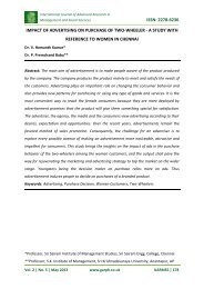
3.8. Comparison <strong>of</strong> percentage <strong>removal</strong> for sample A & sample B<br />
S.No Stage<br />
% <strong>removal</strong> in % <strong>removal</strong> in<br />
sample A<br />
sample B<br />
1. Inlet -- --<br />
2. Stage 1 23 18<br />
3. Stage 2 64 60.5<br />
4. Stage 3 83 81.5<br />
5. Stage 4 86.5 87<br />
Table 6: percentage <strong>of</strong> <strong><strong>co</strong>lour</strong> <strong>removal</strong> for both <strong>dye</strong> samples<br />
100<br />
90<br />
80<br />
% Removal <strong>of</strong> <strong><strong>co</strong>lour</strong><br />
70<br />
60<br />
50<br />
40<br />
30<br />
20<br />
10<br />
0<br />
0 0.5 1 1.5 2 2.5 3 3.5 4 4.5<br />
Stage<br />
Torquise Blue Dye<br />
Remozol Yellow Dye<br />
CONCLUSION<br />
Figure 6: Comparison <strong>of</strong> <strong><strong>co</strong>lour</strong> <strong>removal</strong> for <strong>the</strong> samples<br />
The main objective <strong>of</strong> this research is to remove <strong>the</strong> <strong><strong>co</strong>lour</strong> <strong>from</strong> syn<strong>the</strong>tic <strong>textile</strong> <strong>dye</strong><br />
<strong>effluent</strong> by membrane technology. The two <strong>dye</strong>s which are <strong>co</strong>mmonly available in <strong>the</strong><br />
<strong>textile</strong> <strong>effluent</strong> are Torquise blue <strong>dye</strong> and Remozol golden yellow <strong>dye</strong> solutions. The<br />
membrane used for reverse osmosis is cellulose acetate membrane and gravitational force<br />
Vol. 1 | No.4 | October 2012 www.garph.<strong>co</strong>.<strong>uk</strong> IJARIE | 40
International Journal <strong>of</strong> Advanced Research in<br />
IT and Engineering ISSN: 2278-6244<br />
is used as a major driving force. Many <strong>of</strong> <strong>the</strong> systems <strong>of</strong> separation use pressure gradient as<br />
<strong>the</strong> main driving force, but here we are keeping gravitational force as <strong>the</strong> main driving force<br />
with less amount <strong>of</strong> inlet pressure. These two different <strong>dye</strong> samples are passed through <strong>the</strong><br />
<strong>co</strong>lumn which <strong>co</strong>ntains <strong>the</strong> cellulose acetate membrane and <strong>the</strong> outlet <strong>co</strong>ncentrations are<br />
measured at different stages using calorimeter. The result shows that around 90% <strong>of</strong> <strong>the</strong><br />
<strong><strong>co</strong>lour</strong> is removed by using cellulose acetate membrane in reverse osmosis process.<br />
Acknowledgment<br />
The authors are gratefully thanked to <strong>the</strong> authorities <strong>of</strong> Adama Science & Technology<br />
University, Ethiopia for providing facilities to carry out <strong>the</strong> research work.<br />
REFERENCES<br />
1. Banat.M.I et al (1996), Microbial de<strong>co</strong>lorization <strong>of</strong> <strong>textile</strong> <strong>dye</strong> <strong>co</strong>ntaining <strong>effluent</strong>s,<br />
Bioresource Technology, Vol.58, pp.217-227.<br />
2. Bandini.S et al (1992), Separation efficiency in vacuum membrane distillation, Journal<br />
<strong>of</strong> Membrane Science, Vol.73, pp.217-229.<br />
3. Findley et al (1967), Vaporization through porous membranes, International Journal<br />
<strong>of</strong> Engineering Chemistry, Vol.6, pp.226-230.<br />
4. Findley et al (1969), Mass and heat transfer relations in evaporation through porous<br />
membranes, AIChE Journal, Vol.15, pp.483-489.<br />
5. Hafez.A.I. et al (2004), RO membrane <strong>removal</strong> <strong>of</strong> unreacted chromium for spent<br />
tanning <strong>effluent</strong>, Desalination, Vol.144, pp.237-242.<br />
6. Hanbury et al (1985), Membrane distillation - an assessment, Se<strong>co</strong>nd World<br />
Congress, Desalination & Water Research, Vol.3, pp.287-297.<br />
7. Idris.A et al (2007), Performance <strong>of</strong> cellulose acetate-polye<strong>the</strong>rsulphone blend<br />
membrane prepared using microwave heating for palm oil mill <strong>effluent</strong> treatment,<br />
Water Science and Technology, Vol.56, No.8, pp.169-177.<br />
8. Jonsson et al (1985), Membrane distillation - A <strong>the</strong>oretical study <strong>of</strong> evaporation<br />
through micro porous membranes, Desalination, Vol.56, pp.237-249.<br />
9. Kamilaki A (2000), The <strong>removal</strong> <strong>of</strong> reactive <strong>dye</strong>s <strong>from</strong> <strong>textile</strong> <strong>effluent</strong>s, Ph.D <strong>the</strong>sis,<br />
University <strong>of</strong> Leeds, UK.<br />
Vol. 1 | No.4 | October 2012 www.garph.<strong>co</strong>.<strong>uk</strong> IJARIE | 41
International Journal <strong>of</strong> Advanced Research in<br />
IT and Engineering ISSN: 2278-6244<br />
10. Lawson.K.W et al (1997), Review membrane distillation, Journal <strong>of</strong> Membrane<br />
Science, Vol.124, pp.1-25.<br />
11. Louren<strong>co</strong>.N.D et al (2000), Reactive <strong>textile</strong> <strong>dye</strong> <strong><strong>co</strong>lour</strong> <strong>removal</strong> in a sequencing batch<br />
reactor, Biotechnology Progress, Vol.16, pp.979-985.<br />
12. Michael E. Williams (2003), A review <strong>of</strong> waste water treatment by reverse osmosis,<br />
EET Corporation and Williams Engineering services <strong>co</strong>mpany, pp.1-33.<br />
13. Pearce.C.I. et al (2003), The <strong>removal</strong> <strong>of</strong> <strong><strong>co</strong>lour</strong> <strong>from</strong> <strong>textile</strong> waste water using whole<br />
bacteria cells: a review, Dyes and Pigments, Vol.58, pp.179-196.<br />
14. Robinson.T et al (2001), Remediation <strong>of</strong> <strong>dye</strong>s in <strong>textile</strong> <strong>effluent</strong>, Bioresource<br />
Technology, Vol.77, pp.247-255.<br />
15. Roper.D.K et al (1995), Separation <strong>of</strong> biomolecules using adsorptive membranes,<br />
Journal <strong>of</strong> Chromatography, Vol.70, pp.3-26.<br />
16. Sch<strong>of</strong>ield et al (1987), Heat and mass transfer in membrane distillation, Journal <strong>of</strong><br />
Membrane Science, Vol.33, pp.299-313.<br />
17. Slokar.Y.M et al (1998), Methods <strong>of</strong> de<strong>co</strong>loration <strong>of</strong> <strong>textile</strong> waste water, Dyes and<br />
Pigments, Vol.37, pp.335-356.<br />
18. Strickland.A.F. et al (1995), De<strong>co</strong>loration <strong>of</strong> <strong>co</strong>ntinuous <strong>dye</strong>ing waste water by<br />
ozonation, Textile Chemists and Colorist, Vol.27, pp.11-15.<br />
19. Tamim Younos et al (2005), Overview <strong>of</strong> desalination techniques, Journal <strong>of</strong><br />
Contemporary Water Research & Education, Vol.132, pp.3-10.<br />
20. Willimot.N.J (1997), The use <strong>of</strong> bacteria polymer <strong>co</strong>mposites for <strong>the</strong> <strong>removal</strong> <strong>of</strong> <strong><strong>co</strong>lour</strong><br />
<strong>from</strong> reactive <strong>dye</strong> <strong>effluent</strong>, Ph.D <strong>the</strong>sis, University <strong>of</strong> Leeds, UK.<br />
21. Willimott.N.J, et al (1998), The biotechnology approach to <strong><strong>co</strong>lour</strong> <strong>removal</strong> <strong>from</strong><br />
<strong>textile</strong> <strong>effluent</strong>, JSDC, Vol.114, pp.38-41.<br />
22. Zhaoan Chen et al (2004), Preparation and performance <strong>of</strong> cellulose acetate<br />
/polyethyleneimine blend micro filtration membranes and <strong>the</strong>ir applications, Journal<br />
<strong>of</strong> Membrane Science, Vol. 235, pp. 73 - 86.<br />
Vol. 1 | No.4 | October 2012 www.garph.<strong>co</strong>.<strong>uk</strong> IJARIE | 42