New Style Guide Universal - ELSINCO
New Style Guide Universal - ELSINCO
New Style Guide Universal - ELSINCO

You also want an ePaper? Increase the reach of your titles
YUMPU automatically turns print PDFs into web optimized ePapers that Google loves.
Product Brochure<br />
BTS Master <br />
MT8222A<br />
A High Performance – Handheld Base Station Analyzer
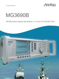
Introducing the Incredibly Accurate, Rugged, Handheld<br />
BTS Master MT8222A<br />
2<br />
Handheld integrated multi-function test tool<br />
RF engineers and technicians in the field need a lightweight, practical,<br />
and rugged test solution that can perform all the measurements needed<br />
for installation and maintenance of modern cell sites. That solution is<br />
the BTS Master MT8222A. It combines the functionality of Anritsu’s<br />
high performance-handheld products, including the MS2721B Spectrum<br />
Master and the MS2024A and MS2026A Cable and Antenna Analyzer.<br />
This combined product weighs less than 4 kg. (9lbs.). The MT8222A provides<br />
users with cable and antenna analysis, spectrum analysis, power meter,<br />
W-CDMA/HSDPA, GSM/GPRS/EDGE, CDMA/EVDO, Fixed WiMAX,<br />
Mobile WiMAX and TD-SCDMA, RF and Demod measurements and<br />
W-CDMA/HSDPA CDMA/EVDO, Mobile WiMAX and TD-SCDMA Over<br />
the Air (OTA), channel scanner, Interference Analyzer, variable Bias Tee, Bit<br />
Error Rate Tester (BERT) and Power Monitor. So technicians can eliminate the<br />
need to carry several independent instruments and instead get the job done<br />
with the MT8222A – an optimal combination of Anritsu’s high performing<br />
handheld instruments.<br />
Easy to use<br />
Coming from the leader in cable and antenna analysis, it’s no surprise that the<br />
BTS Master MT8222A is very easy to operate and requires little or no training.<br />
Users will enjoy the bright 8.5 in. (215 mm.) color TFT display – easy to read<br />
even in broad daylight. Up to six markers can be displayed on the screen<br />
including noise markers and frequency counter markers in the Spectrum<br />
Analyzer mode.<br />
Keep on going – wherever you like<br />
The BTS Master runs for more than 2.5 hours on a single, rechargeable<br />
Li-ion battery. So users have the time and freedom to move from ground<br />
installations to the highest towers, or anywhere where critical measurements<br />
are needed. Plus, when it’s time to replace the battery, it takes no time at all,<br />
and requires no tools.<br />
Eight Built-in Languages<br />
While fluent in English, Spanish, German, French, Japanese, Chinese, Italian<br />
and Korean, the MT8222A user can also customize two additional languages<br />
using Master Software Tools.<br />
Choose from eight different languages or<br />
upload two custom languages.<br />
Eight different languages are offered to<br />
improve technician productivity.
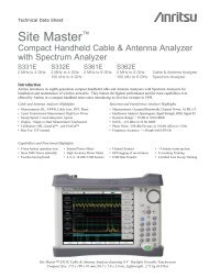
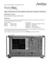
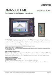
From the Ground Up to the Tower, Accurate and Powerful<br />
Cable and Antenna Analysis in One Handheld Instrument<br />
Date and Time<br />
Instrument Setting<br />
Summary<br />
Function<br />
Hard Keys<br />
Battery Access<br />
GPS Connector<br />
Spectrum<br />
Analyzer<br />
Input<br />
Function Benefits<br />
Frequency<br />
Reference Input<br />
Compact<br />
Flash Slot<br />
RF<br />
Output<br />
Soft Key Active<br />
Function Block<br />
External<br />
Trigger<br />
Input<br />
2.5 mm 3-wire cellular headset connector<br />
USB Jack<br />
W-CDMA/HSDPA<br />
Quickly check base station performance using RF, Demodulation, and Over The Air measurements.<br />
Easily identify HSDPA and W-CDMA OVSF codes by color.<br />
GSM/GPRS/EDGE Rapidly review base station performance via RF and Demodulation measurements.<br />
Fixed WiMAX Check the base station performance with ease using RF and Demodulation measurements.<br />
Mobile WiMAX Automatically decode the DL-MAP to demodulate Mobile WiMAX signals.<br />
Spectrum Analyzer Outstanding performance from 100 KHz to 7.1 GHz<br />
Cable and Antenna Analysis<br />
10 MHz to 4 GHz, 10 MHz to 6 GHz (Option 26): Return Loss, Cable Loss, VSWR, Distance-To-Fault,<br />
2-port Gain, 1-port Phase, 2-port phase, and Smith Chart for detailed analysis.<br />
Power Meter Channelized or Broadband power measurements (no detector needed) from 100 KHz to 7.1 GHz<br />
High Accuracy Power Meter Performs accurate RMS power measurements for CW and modulated signals.<br />
Interference Analyzer Identify interfering signals using Spectrogram display, RSSI, and Signal Strength displays.<br />
RF<br />
Input<br />
LAN Connector<br />
Battery Charger Input<br />
Channel Scanner<br />
Measure frequency, bandwidth and power of multiple transmitted signals. Create 20 custom channels to scan by<br />
frequencies or channels.<br />
Bit Error Rate Tester (BERT) T1, FT1, T3, 2 Mb/s-E1 Capability to analyze if the problem is on the wireline or the wireless side.<br />
GPS Receiver Provides location Information and enhance reference frequency oscillator accuracy.<br />
Speaker<br />
On/Off<br />
Directional<br />
Buttons<br />
Rotary Knob<br />
Soft Keys<br />
Dual Function<br />
Keypad<br />
3
Increase System Uptime with 1-Port Cable<br />
and Antenna Analysis<br />
The BTS Master MT8222A performs a variety of cable and antenna measurements aimed at simplifying the task for the<br />
technician and engineer. A single key selection on the bottom hard keys brings up all the measurements you need.<br />
Frequency Domain Reflectometry (FDR)<br />
Cable and antenna measurements are based on a swept RF signal and are ideal for detecting faults and degradations in the RF<br />
bands. Frequency Domain Reflectometry (FDR) can be used to characterize systems using frequency selective devices (filters,<br />
duplexers, lightning arrestors, antennas, combiners), thus providing an early alert to devastating system failures. Plus, FDR can<br />
track down costly, time consuming problems due to corrosion, slight pin gaps and damaged RF components. By breaking away<br />
from the traditional fix-after-failure maintenance process, FDR techniques find small, hard-to-identify problems before they<br />
become big problems by testing the system at the operating frequency.<br />
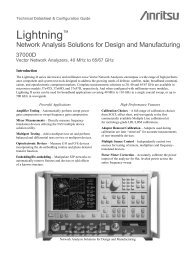
6 GHz Cable and Antenna Analyzer (Option 26)<br />
The 6 GHz Cable and Antenna Analyzer option supports all Cable and Antenna Analyzer functionality and extends<br />
the measurement range from 4 GHz to 6 GHz.<br />
Return Loss measures reflected power<br />
Cable Loss measures energy lost in the cable<br />
Distance-To-Fault finds faults within cable and<br />
feedline system<br />
4<br />
Return Loss/VSWR<br />
Return Loss and VSWR measurements can be used<br />
to characterize cable and antenna systems to ensure conformance to<br />
system specific requirements. Return Loss measures the signal energy<br />
that is “reflected” or returned back to where it came from. Measurements<br />
can be easily toggled between Return Loss and VSWR modes and can be<br />
performed without climbing the tower.<br />
Cable Loss<br />
Usually performed with a short or open at the end of the cable, Cable<br />
Loss measures the energy lost in the cable or transmission line. Since the<br />
MT8222A automatically calculates and displays the average cable loss<br />
over the set frequency range, there's no more need for guesswork or<br />
complicated calculations in the field.<br />
Distance-To-Fault (DTF)<br />
Precisely locate faults within cable and feedline systems using the<br />
MT8222A’s Distance-To-Fault (DTF) measurement. Users will see<br />
magnitude discontinuities displayed in dB or VSWR over distance in<br />
meters or feet. The Distance-To-Fault (DTF) display is obtained by<br />
performing a sweep in the frequency domain and then by using the<br />
inverse Fast Fourier Transform, the data is converted to the time domain.<br />
Distance-To-Fault (DTF) can easily identify connector transitions,<br />
jumpers and kinks in the cable and antenna system. Different windowing<br />
(frequency filters) types give the user the flexibility to trade off sidelobes<br />
for pulse width.
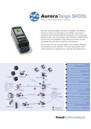
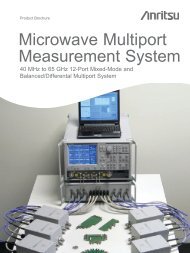
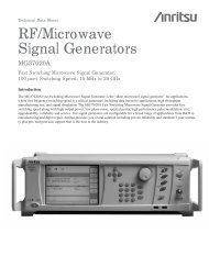
See Overall Tower Top Performance<br />
with 2-Port Cable and Antenna Analysis<br />
Many cellular/PCS and 3G base stations today use diplexers, duplexers, and Tower Mounted Amplifiers (TMAs) to extend<br />
the coverage of the uplink signal – adding a host of complexities for technicians working on these systems. To help simplify<br />
performance verification, the MT8222A allows users to take advantage of 2-port measurements to make gain, isolation, and<br />
insertion loss measurements, as well as to verify the sector-to-sector isolation, TMA and duplexed antennas.<br />
2-PORT<br />
BTS<br />
MASTER<br />
2-Port Gain<br />
2-PORT<br />
BTS<br />
MASTER<br />
RF IN<br />
RF OUT<br />
RF IN<br />
RF OUT<br />
LNA<br />
ANTENNA<br />
ANTENNA<br />
ISOLATION<br />
2-PORT<br />
BTS<br />
MASTER<br />
RF IN<br />
RF OUT<br />
2-Port Gain<br />
The MT8222A simplifies the task of verifying amplifier and<br />
system performance during installation or periodic maintenance<br />
and troubleshooting intervals. Its 2-port Gain measurement features<br />
two different output power levels: High (0 dBm) and Low (–30 dBm).<br />
Low power levels are used to measure the gain of the TMA directly to<br />
ensure that the amplifier does not saturate and that the receiver port<br />
remains unexposed to excess power.<br />
If the TMA has already been installed on the tower, the MT8222A can<br />
measure the relative gain by sending out an RF signal to the transmit<br />
antenna and then measure the received uplink signal with the bias turned<br />
on and off.<br />
Antenna-to-Antenna Isolation<br />
Improving isolation between antenna sectors can reduce cell-to-cell RF<br />
interference and improve system coverage and capacity. An advantage of<br />
the MT8222A is its high power level selection and excellent dynamic<br />
range, ensuring accurate measurements during deployment and during<br />
periodic maintenance intervals. Furthermore, if the antenna has moved<br />
from the installed mounting angle, such as after harsh weather, this<br />
change would be detected in side lobe and back lobe coupling<br />
magnitudes. Additionally, Tx-Rx isolation of duplexers and filters can<br />
be easily tested with the MT8222A’s Dynamic Range performance.<br />
Phase Measurements and Smith Chart<br />
The MT8222A provides 1-port and 2-port phase measurements for<br />
phase matching cables. Using the trace math menu, relative phase<br />
measurements can be made. Technicians can also view impedance<br />
matching results in the Smith Chart display. Markers show real<br />
and imaginary components of the load impedance.<br />
Bias Tee (Option 10)<br />
The optional built-in Bias Tee places adjustable +12V to +24V of<br />
the RF In port and eliminates the need for an external power supply<br />
when biasing an amplifier.<br />
LNA<br />
DUPLEXER<br />
Tx<br />
Rx<br />
LNA<br />
ANTENNA<br />
ANTENNA<br />
TEST<br />
SIGNAL<br />
5
Lab-grade Spectrum Analysis in a Handheld Package<br />
The Occupied Bandwidth screen displays<br />
the amount of spectrum used by a modulated<br />
signal.<br />
Field Strength measurement accurately<br />
corrects the antenna gain or loss.<br />
6<br />
Smart Measurements<br />
Dedicated routines for one-button measurements of field strength, channel<br />
power, occupied bandwidth, Adjacent Channel Power Ratio (ACPR) and<br />
Carrier to Interference Ratio (C/I) make the MT8222A the ideal choice for<br />
the field. Its simple interface significantly reduces test time and increases<br />
analyzer usability, putting more power where it belongs – in the hands of the<br />
technician.<br />
Fast Sweep Speed<br />
The MT8222A automatically sweeps as fast as possible for the selected<br />
settings consistent with accurate results. This allows users to select their<br />
settings and then sweep faster than any portable spectrum analyzer on the<br />
market today, simplifying the capture of intermittent interference signals.<br />
Plus, it’s all done automatically, accurately and consistently.<br />
Occupied Bandwidth<br />
This measurement determines the amount of spectrum used by a modulated<br />
signal. You can choose between two different methods of determining<br />
bandwidth: the percent of power method or the “x” dB down method, where<br />
“x” can be from 1 dB to 100 dB down the skirts of the signal.<br />
Field Strength<br />
To correct the loss or gain of an antenna field strength measurement,<br />
the MT8222A applies an “antenna factor.” The MT8222A will then<br />
automatically adjust the results of the selected antenna frequency band based<br />
on the antenna factor. Plus, you’ll find antenna factors of all the antennas<br />
offered by Anritsu stored in the unit. Antenna factors for all other antennas<br />
can easily be created and saved using Master Software Tools.
Connect Directly or Over the Air to Make<br />
W-CDMA/HSDPA Measurements<br />
With four measurement options; W-CDMA/HSDPA RF Meas, W-CDMA Demod, W-CDMA/HSDPA Demod (covering all<br />
W-CDMA Demod measurements) and W-CDMA/HSDPA Over The Air (OTA) measurements, technicians and RF engineers<br />
can connect the MT8222A to any Node B for accurate RF and Demodulator measurements. A physical connection is not<br />
required for the MT8222A to receive and demodulate W-CDMA and HSDPA OTA signals. With the MT8222A, a technician<br />
no longer needs to take a Node B site off-line.<br />
W-CDMA/HSDPA RF Measurements (Option 44)<br />
RF measurements are used to measure the transmitted signal strength and signal shape of the selected Node B transmitter.<br />
For convenience, the RF measurement option includes Channel Spectrum, Spectral Emission Mask, ACLR and<br />
RF Summary screens.<br />
The RF Spectrum screen shows selected<br />
signals along with key parameters, such as<br />
channel power and occupied bandwidth.<br />
The Spectral Emission Mask screen<br />
presents a received signal framed by the<br />
3GPP spectral mask.<br />
Multichannel ACLR screen shows four main<br />
channels as well as two adjacent channels<br />
power levels.<br />
RF Summary screen displays the transmitter<br />
performance parameters in a table format.<br />
Channel Spectrum<br />
The Channel Spectrum screen displays the signals of a selected channel as well<br />
as channel power (in dBm and watts), occupied bandwidth and peak to average<br />
power. Operators can select a channel by using the band channel or by choosing<br />
a signal standard and channel.<br />
Spectral Emission Mask<br />
The Spectral Emission Mask measurement applies the mask depending upon<br />
the transmitter output as defined in the 3GPP specification (TS 25.141). The<br />
mask varies depending upon the input signal. The MT8222A indicates if the<br />
signal “PASSED” or “FAILED” according to the specified limits. For ease of<br />
analysis, the spectral emission mask is also displayed in a tabular format with<br />
different frequency ranges and a PASS or FAIL indication for each range.<br />
ACLR<br />
The ACLR screen shows measurements of main channel power as well<br />
as the power levels of the adjacent channels set at –10 MHz, –5 MHz,<br />
+5 MHz and +10 MHz according to the 3GPP standard (TS 25.141). The<br />
MT8222A can also make multichannel ACLR measurements with as many<br />
as four main channels and four adjacent channels. See the example with four<br />
main channels and two adjacent channels on both sides.<br />
RF Summary<br />
Technicians can quickly check transmitter performance parameters and<br />
details at a glance in RF Summary screen.<br />
7
Node B Transmitter<br />
Performance Testing Made Simple<br />
The Code Domain Power (CDP) screen shows<br />
256 or 512 OVSF codes with flexible zoom<br />
capabilities.<br />
Code Domain Power Table<br />
The Codogram screen shows how code levels<br />
are changing over time to simplify fault analysis.<br />
8<br />
W-CDMA Demodulator (Option 45)<br />
Demodulates W-CDMA signals and views detailed measurements for<br />
evaluating transmitter modulation performance using Code Domain Power<br />
(CDP), Codogram, Modulation Summary and Pass/Fail screens using<br />
MT8222A with Option 45.<br />
Code Domain Power<br />
The Code Domain Power (CDP) screen displays 256 or 512 OVSF codes<br />
with zoom capability, common pilot power (P-CPICH), channel power, error<br />
vector magnitude (EVM), carrier frequency, carrier feed through, frequency<br />
error (in Hz and ppm), Peak CD error, and noise floor. This view can zoom<br />
to 32, 64, or 128 codes and the user can input the zoom start code to zoom in<br />
on the OVSF codes. The demodulator also displays CPICH, P-CCPCH,<br />
S-CCPCH, PICH, P-SCH and S-SCH power in a dedicated control<br />
channel view.<br />
Code Domain Power Table<br />
The Code Domain Power (CDP) Table screen views all active OVSF codes,<br />
the Spreading Factor, Code, Status, Symbol EVM, modulation type, Relative<br />
Power and Absolute Power – all within the CDP Table screen.<br />
Codogram<br />
Users can take advantage of the Codogram screen display and see how code<br />
levels are changing over time – making it easier to monitor traffic, faults and<br />
hand-off activity. Showing 256 or 512 OVSF codes with zoom codes, the<br />
MT8222A can zoom to 32, 64 or 128 codes, or the user can directly zoom to<br />
particular OVSF codes of interest.
Node B Transmitter<br />
Performance Testing Made Simple<br />
The Modulation Summary screen shows<br />
critical transmitter performance parameters<br />
in table format.<br />
The MT8222A offers a clear Pass/Fail display<br />
for quick evaluation of a Node B base station.<br />
Modulation Summary<br />
The Modulation Summary screen displays critical transmitter performance<br />
measurements in table format for easy viewing, showing carrier frequency,<br />
frequency error, channel power, primary common pilot channel (P-CPICH)<br />
absolute power, secondary common pilot channel (S-CCPCH) power and<br />
paging indicator channel (PICH) as well as physical shared channel (PSCH)<br />
absolute power.<br />
Pass/Fail Mode<br />
The MT8222A stores the five test models covering all eleven test scenarios<br />
specified in the 3GPP specification (TS 25.141) for testing base station<br />
performance and recalls these models for quick easy measurements. After an<br />
operator selects a test model, the MT8222A displays test results in table<br />
format with clear PASS or FAIL indications that include min/max thresholds<br />
and actual measured results.<br />
Using Master Software Tools, additional custom tests can be easily created<br />
and uploaded into the MT8222A. All critical parameters can be selected for<br />
Pass/Fail testing including each individual code’s power level, the spreading<br />
factor and symbol EVM.<br />
9
Demodulate and Display HSDPA Signals with Ease<br />
With Option 65, the MT8222A demodulates<br />
HSDPA and W-CDMA signals and displays the<br />
selected code constellation. The selected code<br />
Power vs. Time is also displayed.<br />
With Option 35, the MT8222A shows<br />
six scrambling codes and CPICH data in<br />
a combination bar graph/table view.<br />
With Option 35 , the MT8222A shows up to 6<br />
mutli-path components of a Scrambling Code,<br />
including total multi-path power in a<br />
comibination bar graph/table view.<br />
10<br />
W-CDMA/HSDPA Demodulator (Option 65)<br />
HSDPA, or High Speed Downlink Packet Access uses up to fifteen dedicated<br />
physical channels to provide high downlink data rates. The BTS Master with<br />
Option 65 allows demodulating HSDPA signals and displaying CDP, selected<br />
code power variation over time, and the constellation for the selected code,<br />
in addition to all the standard W-CDMA demodulator measurements.<br />
W-CDMA/HSDPA Over The Air (Option 35)<br />
OTA has two measurement screens: Scrambling Code and Multi-path. The<br />
Scrambling Code measurement displays six scrambling codes in a bar graph<br />
format. For each scrambling code, CPICH in dBm, Ec/Io in dB, Ec in dBm,<br />
and pilot dominance in dB are displayed in table format. The user will also<br />
see OTA total power in dBm.<br />
The Multi-path measurement displays up to six multi-path components of the<br />
strongest or selected Scrambling Code, measuring Tau in µSec, Tau in Chips,<br />
Distance in feet or meters, Received Signal Code Power, Relative Power and<br />
total Multi-path Power.
Demodulate GSM, GPRS and EDGE<br />
Signals with Ease<br />
GSM/GPRS/EDGE Measurements<br />
For flexibility, the MT8222A features two GSM/GPRS/EDGE measurement modes: RF Meas and Demod. Technicians<br />
and RF Engineers can connect the MT8222A to any GSM/GPRS/EDGE base station for accurate RF and demodulator<br />
measurements. When a physical connection is not required, the MT8222A can receive and demodulate GSM/GPRS/EDGE<br />
signals over the air.<br />
Option 40 displays the first detected timeslot<br />
and mask as specified in 3GPP TS 05.05.<br />
Option 41 demodulates and displays<br />
GSM/GPRS/EDGE signals, including vector<br />
diagrams.<br />
Create and download custom<br />
GSM/GPRS/EDGE Pass/Fail test sets.<br />
GSM/GPRS/EDGE RF Measurements (Option 40)<br />
Examine views of single-channel spectrum, Power vs. Time (frame), Power vs.<br />
Time (slot) with mask per 3GPP TS 05.05 specification and summary screens.<br />
The user can view Channel Spectrum or Multi Channel Spectrums.<br />
The Channel Spectrum screen includes channel power, burst power, average<br />
burst power, frequency error, modulation type and Training Sequence Code.<br />
GSM/GPRS/EDGE Demodulator (Option 41)<br />
Option 41 demodulates GSM/GPRS/EDGE signals and displays the results<br />
of detailed measurements to analyze transmitter modulation performance.<br />
Results are shown for phase error (rms), phase error peak, EVM (rms), EVM<br />
(peak), origin offset, C/I, modulation type and magnitude error (rms) with an<br />
I/Q vector diagram of the signal.<br />
Pass/Fail Mode<br />
Using Master Software Tools, custom GSM/GPRS/EDGE Pass/Fail test sets<br />
can be easily created and uploaded into the MT8222A. The test results are<br />
displayed in table format with clear Pass or Fail indicators that include<br />
min/max thresholds and actual measured results.<br />
11
Connect Directly or Over the Air to Make<br />
CDMA/EVDO Measurements<br />
CDMA RF Measurements (Option 42)<br />
RF Measurements are used to measure the transmitted signal power, shape, power in adjacent channels and spurious<br />
emissions. The following sets of measurements help the technician evaluate the RF characteristics of a CDMA base station.<br />
CDMA Channel Spectrum measurement<br />
display<br />
CDMA Spurious Emissions measurement<br />
display<br />
12<br />
Channel Spectrum<br />
The Channel Spectrum measurement displays the spectrum of the specified<br />
channel in addition to numerical values for Channel Power, Occupied BW<br />
and Peak to Average Ratio.<br />
ACPR<br />
The ACPR measurement displays the main channel and the power of two<br />
adjacent channels on each side of a bar graph. The user can configure up to<br />
five main channels.<br />
Spurious Emission<br />
This measurement displays the spectrum of the input signal at specific<br />
offsets (based upon the Signal Standard). Markers are automatically tuned to<br />
measure the input power at these offsets and to determine a PASS or FAIL<br />
according to limits that are set by the signal standard. A blue mask is also<br />
calculated and shown on the spectrum to visually check for pass fail<br />
conditions.
Evaluate the Quality of the Modulation from<br />
the CDMA Base Station<br />
cdmaOne and CDMA2000 1xRTT Demodulator (Option 43)<br />
Demodulator measurements are used to measure the code domain power in both graphical and tabular forms.<br />
The following sets of measurements help the technician evaluate the quality of the modulation from the CDMA base station.<br />
CDMA Code Domain Power measurement<br />
display<br />
cdmaOne and CDMA2000 1xRTT Over The Air (Option 33)<br />
Over The Air Measurement provides a cost effective way to identify base station performance problems before they<br />
become catastrophic without taking the base station off the air. Traditionally, technicians had to bring down the sector or site<br />
to test the base station performance. Now technicians can sit in a vehicle and make these measurements. For accurate<br />
measurements over the air, a GPS antenna should be used to provide a timing reference.<br />
CDMA Over the Air measurement display<br />
CDP<br />
The Code Domain Power measurement displays the power of the various<br />
demodulated codes (display is automatically bit reversed if Walsh Codes are set<br />
to 128). Rho, Frequency Error, Average Noise Floor and Tau are numerical<br />
values that are calculated and displayed. A zoom view of 16, 32 or 64 codes<br />
is also seen. Markers can be turned on to display the code power and code type.<br />
CDP Table<br />
This measurement displays all the active codes in a color coded tabular<br />
format.<br />
Pilot Scan<br />
The strongest nine received PNs are displayed as bar graphs, and the PN<br />
numbers are displayed at the bottom of the bar graphs. For each PN, a table<br />
displays PN number, Ec/Io, and Tau. Also shown are Pilot Power, Channel<br />
Power, and Pilot Dominance.<br />
MultiPath<br />
The strongest six paths are displayed. For each path, a table below the bar<br />
graph displays Ec/Io and Tau. Also shown are Channel Power and Multipath<br />
Power.<br />
13
Optimize EVDO Network Performance<br />
EVDO<br />
With the 3G evolution of CDMA technology, 1xEV-DO provides data rates up to 2.4 Mbps, providing greater system<br />
capacity and lower costs, making wireless broadband possible. The CDMA2000 1xEV-DO (EVDO) system is backward<br />
compatible and is spectrally identical to the cdmaOne and CDMA2000 systems.<br />
EVDO RF Measurements (Option 62)<br />
RF Measurements are used to measure the transmitted signal power, shape, power in adjacent channels and spurious emissions.<br />
The following sets of measurements help the technician evaluate the RF characteristics of an EVDO base station.<br />
EVDO Power vs. Time measurement<br />
display<br />
EVDO Demodulator (Option 63)<br />
Demodulator measurements are used to measure the code domain power in both graphical and tabular forms. The following<br />
sets of measurements help the technician evaluate the quality of the modulation from the EVDO base station.<br />
EVDO CDP MAC measurement display<br />
14<br />
Channel Spectrum<br />
The Channel Spectrum measurement displays the spectrum of the specified<br />
channel in addition to numerical values for Channel Power, Occupied BW and<br />
Peak to Average Ratio.<br />
Power vs Time<br />
This measurement displays the time domain view of an EVDO half-slot and<br />
helps determine the % of idle activity which gives a measure of how many<br />
users are connected to the base station.<br />
ACPR<br />
The ACPR measurement displays the main channel and the power of two<br />
adjacent channels on each side of a bar graph. The user can configure up to five<br />
main channels.<br />
Spurious Emission<br />
This measurement displays the spectrum of the input signal at specific offsets<br />
(based upon the Signal Standard). Markers are automatically tuned to measure<br />
the input power at these offsets and to determine a PASS or FAIL according to<br />
limits that are set by the signal standard. A blue mask is also calculated and<br />
shown on the spectrum to visually check for pass fail conditions.<br />
CDP MAC<br />
This measurement displays the power of the various demodulated codes in the<br />
MAC Channel. Pilot and MAC Power, Rho, Frequency Error, and Average<br />
Noise Floor are numerical values that are calculated and displayed. A zoom<br />
view of 16, 32 or 64 codes is also seen. Markers can be turned on to display<br />
the code power and code type.<br />
CDP Data<br />
This measurement displays the power of the 16 I and 16 Q sub-channels of<br />
the Data channel separately.<br />
MAC CDP Table<br />
This measurement displays all the active codes in the MAC channel in a color<br />
coded tabular format.
Cost Effective Way to Identify Base Station<br />
Performance Problems<br />
EVDO Over The Air (Option 34)<br />
Over The Air Measurement provides a cost effective way to identify base station performance problems before they<br />
become catastrophic without taking the base station off the air. Traditionally, technicians had to bring down the sector or site<br />
to test the base station performance. Now technicians can sit in a vehicle and make these measurements. For accurate<br />
measurements over the air, a GPS antenna should be used to provide a timing reference.<br />
EVDO Over the Air measurement display<br />
EVDO Pass Fail Mode measurement display<br />
Pilot Scan<br />
The strongest nine received PNs are displayed as bar graphs, and the PN<br />
numbers are displayed at the bottom of the bar graphs. For each PN, a table<br />
displays PN number, Ec/Io, and Tau. Also shown are Pilot Power, Channel<br />
Power, and Pilot Dominance.<br />
MultiPath<br />
The strongest six paths are displayed. For each path, a table below the bar<br />
graph displays Ec/Io and Tau. Also shown are Channel Power and Multipath<br />
Power.<br />
Pass/Fail Mode<br />
The Spectrum Master and BTS Master can perform automated Pass/Fail<br />
testing for both CDMA and EVDO. The test results are displayed in table<br />
format with clear PASS or FAIL indications that include min/max thresholds<br />
and actual measured results. Using Master Software Tools, custom tests<br />
can be easily created and uploaded into the BTS Master. All critical<br />
parameters can be selected for Pass/Fail testing.<br />
15
Fixed WiMAX Measurements Made Simple<br />
The Fixed WiMAX 802.16-2004 specification refers to an air interface standard for Broadband Wireless Access systems.<br />
It enables multiple services in a wireless metropolitan area network, such as wireless backhaul for telecommunications, E1/T1<br />
replacement for small and medium businesses and residential wireless cable/DSL for broadband internet at home. Also, WiMAX<br />
provides fixed, nomadic, portable and mobile wireless broadband connectivity without the need for a direct line-of-sight<br />
connectivity between a base station and a subscriber.<br />
MT8222A provides two WiMAX measurement options: Fixed WiMAX RF Meas and Fixed WiMAX Demod. So for accurate<br />
RF and demodulator measurements, technicians and RF engineers can connect the Base Station Analyzer, MT8222A to any<br />
Fixed WiMAX Base Station.<br />
Fixed WiMAX RF Measurements (Option 46)<br />
RF measurements are used to measure the transmitted signal strength and signal shape of the selected BTS transmitter.<br />
For the technician’s convenience, the RF measurement option can display Channel Spectrum, Power vs. Time, ACPR and<br />
RF Summary screens.<br />
The RF Spectrum screen shows the signal<br />
spectrum along with key parameters, such as<br />
channel power and occupied bandwidth.<br />
Power vs. Time screen displays the burst<br />
power and preamble power of the signal.<br />
The ACPR screen shows the power levels for<br />
the main channel and two adjacent channels.<br />
16<br />
Spectrum<br />
In the Spectrum screen, technicians can view and examine the selected signal’s<br />
channel power (in dBm) and occupied bandwidth.<br />
Power vs. Time<br />
The Power vs. Time screen shows the time domain view of a Fixed WiMAX<br />
OFDM signal. The Preamble power is always 3 dB higher than the data power.<br />
The channel power, preamble power, burst power of data bursts in dBm and<br />
the Crest Factor are displayed as numerical values.<br />
ACPR<br />
ACPR is the ratio of the amount of leakage power in an adjacent channel<br />
to the total transmitted power in the main channel. With the MT8222A,<br />
technicians can easily inspect measurements of main channel power as well<br />
as the power levels of the two adjacent channels on each side.
Demodulate Fixed WiMAX Signals with Ease<br />
Option 47 displays the constellation of the<br />
demodulator signal.<br />
Spectral Flatness is displayed with the mask<br />
as specified in 802.16-2004.<br />
EVM vs. Sub Carrier displays pilot and data<br />
subcarrier.<br />
The EVM vs. Symbol displays the EVM (rms)<br />
values vs. OFDM Symbols.<br />
Using Master Software Tools create and download<br />
custom Fixed WiMAX Pass/Fail test sets.<br />
Fixed WiMAX Demodulator (Option 47)<br />
With Option 47, the MT8222A can demodulate Fixed WiMAX OFDM<br />
signals and displays detailed measurements for evaluating transmitter<br />
modulation performance using Constellation, Spectral Flatness,<br />
EVM vs. Sub carrier, and EVM vs. Symbol.<br />
Constellation<br />
The Constellation view shows the constellation of the demodulated data symbols<br />
over 1 frame. The data bursts can have BPSK, QPSK, 16 QAM or 64 QAM<br />
modulations. All the modulations are color coded. The screen also displays RCE<br />
(rms) in dB, RCE (pk) in dB, EVM (rms) in %, EVM (pk) in %, Freq Error in<br />
Hz, Freq Error in ppm, Carrier Frequency in Hz and Base Station ID.<br />
Spectral Flatness<br />
The Spectral Flatness view displays the data collected from the preamble<br />
before channel estimation is performed. The deviation of the spectral flatness<br />
from the average over all the carriers is shown in dB. A mask that conforms<br />
to the 802.16-2004 specification is displayed as green/red lines depending on<br />
the measurement value. The absolute delta of the power between adjacent sub<br />
carriers in dB is also displayed.<br />
EVM vs. Sub Carrier<br />
The EVM vs. Sub Carrier screen displays the EVM (rms) values vs. OFDM<br />
sub carriers. The pilot and data sub carriers are displayed and color-coded.<br />
EVM vs. Symbol<br />
The EVM vs. Symbol screen displays the EVM (rms) values vs.<br />
OFDM Symbols.<br />
Pass/Fail Mode<br />
The MT8222A has the capability of creating test procedures with minimum<br />
and maximum limits for testing base station performance and recalls these<br />
tests for quick and easy measurements. After a test procedure, the MT8222A<br />
can display test results in table format with clear PASS or FAIL indications<br />
that include min/max thresholds and actual measured results. Plus using<br />
Master Software Tools, additional custom tests can be easily created and<br />
uploaded into the MT8222A.<br />
17
RF Mobile WiMAX Measurements Made Simple<br />
The Mobile WiMAX 802.16-2005 specification refers to an air interface standard for Broadband Wireless Access systems.<br />
It enables multiple services in a high speed wireless network, such as wireless backhaul for telecommunications, E1/T1<br />
replacement for small and medium businesses, wireless cable/DSL for broadband internet at home or on the move, video on<br />
demand and voice over IP services. Also, WiMAX provides, nomadic, portable and mobile wireless broadband connectivity<br />
without the need for a direct line-of-sight connectivity between a base station and a subscriber.<br />
The RF Spectrum screen shows the signal<br />
spectrum along with key parameters, such<br />
as channel power and occupied bandwidth.<br />
Power vs. Time screen displays the burst<br />
power and preamble power of the signal.<br />
The ACPR screen shows the power levels for<br />
the main channel and two adjacent channels.<br />
The WiMAX Summary screen shows all key<br />
measured parameters of the Mobile WiMAX<br />
signal, there are three summary screens,<br />
Mobile WiMAX RF, Mobile WiMAX demod and<br />
a combined RF & demod Summary screen.<br />
18<br />
The MT8222A provides three Mobile WiMAX measurement options:<br />
Mobile WiMAX RF Measurements, Mobile WiMAX Demodulator and<br />
Mobile WiMAX Over The Air (OTA) measurements. So for accurate RF<br />
and demodulator measurements, technicians and RF engineers can connect<br />
the Base Station Analyzer, MT8222A to any Mobile WiMAX Base Station.<br />
Mobile WiMAX RF Measurements (Option 66)<br />
RF measurements are used to measure the transmitted signal strength and<br />
signal shape of the selected BTS transmitter. For the technician’s convenience,<br />
the RF measurement option can display Channel Spectrum, Power vs. Time,<br />
ACPR and RF Summary screens.<br />
Spectrum<br />
In the Spectrum screen, technicians can view and examine the selected<br />
signal’s channel power (in dBm) and occupied bandwidth.<br />
Power vs. Time<br />
The Power vs. Time screen shows the time domain view of a Mobile WiMAX<br />
OFDMA signal in either 5 ms or 10 ms frames. The different power vs. time<br />
components of a Mobile WiMAX signal are measured and displayed as channel<br />
power, preamble power, downlink burst power and uplink burst power in dBm.<br />
ACPR<br />
ACPR is the ratio of the amount of leakage power in an adjacent channel<br />
to the total transmitted power in the main channel. With the MT8222A,<br />
technicians can easily inspect measurements of main channel power as well<br />
as the power levels of the two adjacent channels on each side.<br />
WiMAX Summary<br />
Technicians can quickly view key measurement parameters in the various<br />
Summary screens. The WiMAX RF summary screen displays channel power,<br />
preamble power, DL burst power and UL burst power and occupied bandwidth.<br />
The WiMAX demod summary screen displays RCE (Relative Constellation<br />
Error) rms and peak, EVM (Error Vector Magnitude) rms and peak, carrier<br />
frequency, frequency error Hz and ppm, Base Station ID and sector ID.<br />
The WiMAX Summary is a compilation of both RF and demod<br />
measurements together.
Demodulate Mobile WiMAX<br />
The constellation screen displays the different<br />
modulation formats of the demodulated signal<br />
using color codes, QPSK (purple), 16QAM<br />
(green), 64 QAM (yellow).<br />
Spectral flatness uses the specified<br />
802.16-2005 mask for pass fail analysis<br />
The EVM vs. Sub Carrier displays the EVM of<br />
individual subcarriers.<br />
The EVM vs. Symbol displays the EVM<br />
values of the OFDMA symbols.<br />
DL MAP screen displays the DL MAP zone<br />
information in a decision tree format.<br />
Mobile WiMAX Demodulator (Option 67)<br />
With Option 67, the MT8222A can demodulate Mobile WiMAX OFDMA<br />
signals and displays detailed measurements for evaluating transmitter<br />
modulation performance using Constellation, Spectral Flatness, EVM vs.<br />
Sub carrier, and EVM vs. Symbol and it can automatically decode the DL<br />
MAP. For faster go no-go testing, a technician can specify to only<br />
demodulate the FCH (Frame Control Header).<br />
Constellation<br />
The Constellation view shows the constellation of the demodulated<br />
data symbols over one frame. The data bursts can have QPSK, 16 QAM or<br />
64 QAM modulations. Each modulation format is color coded for easy<br />
identification. The screen also displays RCE (rms) in dB, RCE (pk) in dB,<br />
EVM (rms) in %, EVM (pk) in %, Freq Error in Hz, Freq Error in ppm,<br />
Base Station ID and Sector ID.<br />
Spectral Flatness<br />
The Spectral Flatness view displays the data measured from the preamble<br />
before channel estimation is performed. The deviation of the spectral flatness<br />
from the average over all the carriers is shown in dB. A mask that conforms<br />
to the 802.16-2005 specification is displayed as green lines, the mask turns<br />
red when the measured value crosses the mask. The absolute delta of the<br />
power between adjacent sub carriers in dB is also displayed.<br />
EVM vs. Sub Carrier<br />
The EVM vs. Sub Carrier screen displays the EVM (rms) values vs.<br />
OFDMA sub carriers. The number of sub carriers will vary depending on the<br />
bandwidth of the signal.<br />
EVM vs. Symbol<br />
The EVM vs. Symbol screen displays the EVM (rms) values vs. OFDMA<br />
Symbols. The values displayed are a composite of all sub carriers.<br />
DL MAP<br />
The MT8222A can automatically decode the DL MAP information from the<br />
Mobile WiMAX carrier, thereby simplifying the testing of the demodulated<br />
Mobile WiMAX signals. The DL MAP screen displays the decoded DL MAP<br />
zone information and all relevant data associated with each individual burst<br />
in a zone. If the instrument is set to manual demodulation the DL MAP<br />
parameters from the XML file specified is shown.<br />
19
Make Over the Air Mobile WiMAX Measurements<br />
Mobile WiMAX OTA (Over The Air) (Option 37)<br />
With Option 37, the MT8222A has basic drive test capability with it’s channel monitor measurement that combines the<br />
channel power measurement made over time with the GPS location information (requires Option 31) of the instrument, this<br />
information can be saved to either internal or external memory for export to post processing software such as Mapinfo or<br />
MapPoint, which can display Mobile WiMAX power levels over a geographic area.<br />
The Channel Power Monitor data can be plotted on a map.<br />
20<br />
Channel Power Monitor<br />
The channel power monitor view captures Mobile WiMAX channel<br />
power continuously or for a specified time, the user can also select the<br />
time interval to capture measurements and can set the instrument to<br />
automatically save the data, if the optional GPS receiver is turned on<br />
the captured data will also have the longitude/latitude and time<br />
information tagged to each measurement.
RF TD-SCDMA Measurements Made Simple<br />
TD-SCDMA Analyzer offers three different measurement modes – RF Measurements, Demodulator and Over the Air<br />
Measurements. These options help RF engineers and technicians to make accurate RF and Demodulation measurements by<br />
connecting the MT8222A to any Node B. A physical connection is not required for the MT8222A to receive and demodulate<br />
TD-SCDMA OTA signals. With the MT8222A, a technician no longer needs to take a Node B site off-line.<br />
TD-SCDMA RF Measurements (Option 60)<br />
RF measurements are used to measure the transmitted signal strength and signal shape of the selected Node B transmitter.<br />
The RF measurement option includes Channel Spectrum, Power vs. Time and RF Summary screens.<br />
Power vs. Time screen displaying a full frame<br />
of a TD-SCDMA signal.<br />
Power vs. Time screen displaying a selected<br />
slot in a Frame.<br />
Channel Spectrum<br />
The Channel Spectrum screen displays the signals of a selected channel as<br />
well as channel power (in dBm or watts), occupied bandwidth. In addition,<br />
the left and right channel powers and occupied bandwidths are also displayed.<br />
Power vs. Time<br />
The Power vs. Time screen displays the power over the frame of the signal.<br />
The display can also be configured to zoom in on a selected slot. In the<br />
frame view, individual slot powers are displayed along with Channel Power<br />
RRC, UpPTS Power, DwPTS Power, ON/OFF Ratio, Slot Peak to Average<br />
Ratio and Downlink – Uplink Delta Power.<br />
21
Demodulate TD-SCDMA Signals with Ease<br />
TD-SCDMA Demodulator (Option 61)<br />
Demodulation measurements are used to measure the modulation performance of the transmitted signal of the selected Node B<br />
transmitter. The Demodulator measurement option includes Code Domain Power Data screen and Demod Summary screens.<br />
Code Domain Power of the Data Codes is<br />
displayed as a bar graph along with the Code<br />
Domain Error.<br />
Over the Air Code Scan displays all 32 codes<br />
and its Ec/Io and Tau.<br />
Over the Air Tau Scan.<br />
Automated Pass/Fail testing for TD-SCDMA.<br />
22<br />
Code Domain Power (CDP) Data<br />
The CDP Data screen displays the power of the 16 codes of a demodulated<br />
TD-SCDMA Signal. The Code Domain Power and Code Domain Error of the<br />
codes are displayed as a bar graph. Other measurement results include Slot<br />
Power, Frequency Error in Hz, EVM and Peak EVM, DwPTS Power, Tau,<br />
Noise Floor, and Peak Code Domain Error.<br />
TD-SCDMA Over the Air (OTA) Measurements (Option 38)<br />
Over the Air Measurements provide the user with an easy way to monitor all<br />
32 SYNC-DL codes outside a base station. The MT8222A displays the codes<br />
in two convenient formats sorted by codes or by Tau, indicating distance<br />
from a base station. The Code scan view displays all 32 codes in a bar graph<br />
with their individual Ec/Io and Tau. The Code scan view also displays the<br />
DwPTS Power and the Pilot Dominance. The Tau scan displays the code<br />
power in the Y axis and the Tau in the X axis. In addition, a table below the<br />
graph displays six of the strongest codes sorted by power.<br />
Pass/Fail Mode<br />
The BTS Master can perform automated Pass/Fail testing for TD-SCDMA<br />
signals. The test results are displayed in table format with clear PASS or<br />
FAIL indications that include min/max thresholds and actual measured<br />
results. Using Master Software Tools, custom tests can be easily created and<br />
uploaded into the BTS Master. All critical parameters can be selected for<br />
Pass/Fail testing.
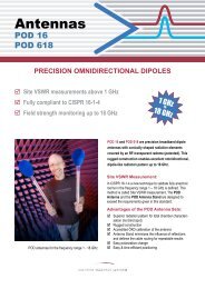
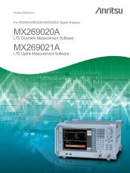
Enhance Frequency Accuracy with Built-in GPS<br />
GPS (Option 31)<br />
The GPS option is used to confirm and save the exact measurement, location (longitude, latitude), date and time for each<br />
measurement. This option also comes with a magnet mount antenna with a 5m (15 foot) cable, for convenient use on a car<br />
roof or other surfaces.<br />
GPS location information (longitude, latitude)<br />
is shown at the top of the screen.<br />
The MT8222A can easily enhance the<br />
frequency reference oscillator accuracy to<br />
make precise frequency error measurements.<br />
Drift in PPB<br />
–5<br />
–10<br />
The GPS Option 31 also enhances the frequency accuracy of the MT8222A’s<br />
internal OCXO oscillator. Within three minutes of GPS satellite acquisition,<br />
the built-in GPS receiver provides a frequency accuracy to better than 25 ppb<br />
(parts per billion). After disconnection of the GPS antenna, the instrument<br />
will remain in High-Accuracy mode for three days, preserving frequency<br />
accuracy to better than 50 ppb.<br />
5<br />
0<br />
–15<br />
25 50 25 0 25 50 25 0 25 50 25 0 25<br />
One hour at each individual temperature (x-axis)<br />
Drift in PPB<br />
5<br />
0<br />
Typical frequency accuracy of the MT8222A for 72 hours following the GPS antenna disconnect<br />
over full specified temperature range.<br />
Typical frequency accuracy of the MT8222A for 24 hours following the GPS antenna disconnect<br />
over temperature range 15° C to 35° C.<br />
–5<br />
25 30 35 30 25 20 15 20 25 30 35 30 25 20 15 20 25 30 35 30 25 20 15 20 25<br />
One hour at each individual temperature (x-axis)<br />
23
Track Down Unwanted Interference<br />
with the MT8222A<br />
Interference Analyzer (Option 25)<br />
With its built-in low-noise preamplifier, the MT8222A with the interference analyzer option provides the ability to identify and<br />
locate interfering signals down to –154 dBm, allowing technicians to better address the quality issues that affect user service.<br />
Spectrogram measurements identifies<br />
intermittent interference.<br />
RSSI measurement analyzes signal strength<br />
of a signal over time.<br />
Using the Signal Strength Meter makes<br />
locating an interfering signal easy.<br />
24<br />
Spectrogram<br />
For identifying intermittent interference and tracking signal levels over time,<br />
the Spectrogram display provides a three dimensional display of frequency,<br />
power, and time of the spectrum. And the MT8222A can collect this data for<br />
up to 72 hours.<br />
RSSI<br />
RSSI indicator can be used to observe the signal strength of a single<br />
frequency over time. Data can be collected for up to 72 hours.<br />
Signal Strength Meter<br />
The Signal Strength Meter can locate an interfering signal, by using<br />
a directional antenna and measuring the signal strength. Power is displayed<br />
in watts, dBm, in the graphical analog meter display and also by an audible<br />
beep proportional to its strength. For accurate field strength measurements<br />
by using an appropriate calibrated antenna, the MT8222A can automatically<br />
convert power to field strength.
Track Down Unwanted Interference<br />
with the MT8222A<br />
Signal ID feature showing scanned results of<br />
the whole band.<br />
Signal ID feature showing scanned results of<br />
a particular frequency.<br />
Channel Scanner measures power of multiple<br />
transmitters.<br />
Signal ID<br />
The Signal ID feature in the interference Analyzer can help to quickly<br />
identify the type of the interfering signal. This measurement can be<br />
configured to identify all signals in the selected band or just monitor one<br />
single interfering frequency. The results displayed include the Center<br />
Frequency, Bandwidth of the signal, the type of the signal (CDMA, GSM<br />
and WCDMA); its closest channel number, the number of carriers, its Signal<br />
to Noise ratio and the Channel Power of the signal. The spectrum of the<br />
signal is colored to ease review of the scanned signals.<br />
Channel Scanner (Option 27)<br />
The Channel Scanner option measures the power of multiple transmitted signals,<br />
making it very useful for measuring channel power of up to 20 channels in<br />
AMPS, iDEN, GSM, TDMA, CDMA, W-CDMA, and HSDPA networks – all<br />
at the same time. Users can select the frequencies or the scanned data – to be<br />
displayed by frequencies or the channel number. View display data in easy to<br />
read graph or table format. And in the custom setup menu each channel can be<br />
custom built with different frequency bandwidth, or channels from different<br />
signal standards.<br />
25
Extend Functionality with Valuable Options<br />
Power Meter measures total input power in a<br />
selected frequency span.<br />
Measure broadband power up to 50 GHz.<br />
with the Power Monitor.<br />
High Accuracy Power Meter provides true RMS<br />
measurements from –30 dBm to +20 dBm.<br />
CW Signal Generator has a high and low<br />
power setting.<br />
26<br />
Power Meter (Standard)<br />
The internal Power Meter uses the spectrum analyzer circuitry to measure the<br />
power (no external sensor is required). Select frequency to make channelized<br />
power measurement over specific channels, or broadband measurements over<br />
the entire frequency range. Power is displayed in an analog type display and,<br />
supports both watts and dBm. RMS averaging can be set to low, medium, or<br />
high. Upper and lower limit lines can be turned on as needed.<br />
Power Monitor (Option 5)<br />
With the Anritsu 560 series detectors, technicians can accurately measure<br />
broadband power up to 50 GHz using precision detectors designed to<br />
minimize mismatch uncertainty. Then, users can view and analyze results in<br />
absolute power (dBm or watts) or relative power (dBr or %). Users will also<br />
find built-in auto averaging automatically reduces the effects of noise while<br />
zeroing control allows optimum measurement accuracy at low power levels.<br />
This detector has a measurement range from –40 dBm to +16 dBm.<br />
High Accuracy Power Meter (Option 19)<br />
Anritsu’s PSN50 sensor makes high accuracy power measurements<br />
from 50 MHz to 6 GHz and provides true RMS measurements<br />
from –30 dBm to +20 dBm. This enables users to make accurate<br />
measurements for CW and digitally modulated signals such as<br />
CDMA/EV-DO, GSM/EDGE, and W-CDMA/HSDPA.<br />
Users will also find:<br />
• Convenient connection via a USB A/mini-B cable<br />
• Power displayed in both dBm and watts<br />
• Optional upper/lower limit activation during Pass/Fail measurements<br />
Option 19 adds support for the PSN50 Sensor, which is purchased separately.<br />
CW Signal Generator (Option 28)<br />
The CW signal generator provides a CW signal source to test low noise<br />
amplifiers, repeaters, and for base stations receiver sensitivity testing.
More Valuable Options<br />
With Option 50, let T1 tester find out if the<br />
problem is on the wireline or the wireless side.<br />
With Option 52, 2 Mb/s - E1 tester can<br />
perform a full complement of 2 Mb/s - E1<br />
and Trau-channels tests.<br />
With Option 53, T3/T1/FT1 tester can complete<br />
T1, Fractional T1 and sub-channel tests.<br />
T1/FT1 Bit Error Rate Tester (Option 51)<br />
The BTS Master performs full T1, Fractional T1 (FT1) and sub-channel<br />
(8 kb, 16 kb) functional tests, simplifying the task of determining if the<br />
source of the problem is on the wireline or the wireless side. The data can be<br />
displayed in a histogram, and the BTS Master can collect the T1 data for up<br />
to three days. The analyzer can also measure the carrier voltage which can be<br />
displayed in dBdsx or peak to peak voltage units. The T1 carrier frequency is<br />
also measured and displayed in Hz.<br />
The user can manually select a DS0/VF channel and listen to the<br />
channel using the BTS Master’s integrated speaker. If there is a test tone on<br />
the channel, the BTS Master displays the signal level and frequency.<br />
E1- 2Mb/s Bit Error Rate Tester (Option 52)<br />
The BTS Master has an optional E1- 2Mb/s functionality that can perform a<br />
full complement of E1- 2Mb/s and sub-channels tests. The E1- 2 Mb/s BERT<br />
analyzer includes both a RJ48 or BNC connector. The ability to have<br />
E1- 2 Mb/s testing in one test tool simplifies troubleshooting problems and<br />
determining if it’s on the wireline or the wireless side. The E1- 2 Mb/s data<br />
can be displayed in multiple formats including a histogram, and the BTS<br />
Master can collect the E1- 2 Mb/s Histogram data for up to three days. The<br />
analyzer can also measure the carrier voltage which can be displayed in<br />
dBdsx or peak to peak voltage units. The E1- 2 Mb/s carrier frequency is also<br />
measured and displayed in Hz. The user can manually select a VF channel<br />
and listen to the channel using the BTS Master’s integrated speaker. If there<br />
is a test tone on the channel, the BTS Master displays the signal level<br />
and frequency.<br />
T3/T1/FT1 Bit Error Rate Tester (Option 53)<br />
The BTS Master’s optional T3 BERT analyzer has not only a full range<br />
of T3 functional tests but also complete T1, Fractional T1 (FT1) and<br />
sub-channel (8 kb, 16 kb) tests. This enhanced capability is key for<br />
high traffic sites using a T3 backhaul. The BTS Master can measure the DS3<br />
carrier exclusively or it can also choose to measure a DS1 and DS0 payload.<br />
The collected data can be displayed in a histogram, the BTS Master can also<br />
collect the T3, T1, FT1 data for up to three days. The analyzer can measure<br />
the carrier voltage which can be displayed in dBdsx or peak to peak voltage<br />
units. The T3, T1, FT1 carrier frequency is also measured and displayed in<br />
Hz. The user can manually select a DS0/VF channel and listen to the channel<br />
using the BTS Master’s integrated speaker. If there is a test tone on the<br />
channel, the BTS Master displays the signal level and frequency.<br />
27
Master Software Tools Augments the Power<br />
of the MT8222A<br />
To further increase the power of the MT8222A, each BTS Master instrument comes with Master Software Tools –<br />
comprehensive data management and analysis software that provides simple and easy methods to manage, archive,<br />
analyze, print and report system performance. For the most current version of Anritsu Master Software Tools,<br />
please visit www.us.anritsu.com.<br />
Master Software Tools simplifies the process of<br />
formatting data and generating reports.<br />
Master Software Tools integrated with MapPoint to<br />
quickly display the geographic location of<br />
measurements with GPS data.<br />
28<br />
With Master Software Tools <br />
the MS8222A can:<br />
(Windows ®<br />
2000/XP/Vista compatible)<br />
■ Automatically update the MT8222A with the latest firmware available<br />
from the Anritsu web site<br />
■ Create and download new Cable Loss signal standards, Pass/Fail Mode<br />
custom lists and antenna factors to existing lists into the unit<br />
■ Store an unlimited number of data traces to a PC – easing the task<br />
of analyzing and monitoring historical performance<br />
■ Coordinate cell site locations using Microsoft ®<br />
MapPoint ®<br />
GPS location mapping<br />
■ Modify existing languages or add two custom languages to the MT8222A<br />
■ Establish a connection to a PC using USB, Ethernet LAN, or<br />
Direct Ethernet<br />
and<br />
■ Export plot data as text files for use in spreadsheets or graphic files<br />
(JPG format)<br />
■ View multiple Spectrum Analyzer measurements on the same screen<br />
using Trace Overlay<br />
■ Capture live traces from the instrument and view them on the PC<br />
■ Add or modify Limit Lines and Markers<br />
■ Handle long file names for easy, descriptive data labeling<br />
■ Obtain VSWR, Cable Loss, Phase or Smith Chart plots from<br />
Return Loss measurement
Ordering Information<br />
MT8222A - BTS Master<br />
Standard<br />
Cable and Antenna Analyzer<br />
Frequency Range: 10 MHz to 4 GHz<br />
Spectrum Analyzer<br />
Frequency Range: 100 kHz to 7.1 GHz<br />
Power Meter<br />
Frequency Range: 100 kHz to 7.1 GHz<br />
Optional<br />
Interference Analyzer<br />
Frequency Range: 100 kHz to 7.1 GHz<br />
Channel Scanner<br />
Frequency Range: 100 kHz to 7.1 GHz<br />
W-CDMA/HSDPA Analyzer<br />
Frequency Range: 824 to 894 MHz, 1710 to 2170 MHz, and 2300 to 2700 MHz<br />
GSM/GPRS/EDGE Analyzer<br />
Frequency Range: 380 to 400 MHz, 410 to 430 MHz, 450 to 468 MHz,<br />
478 to 496 MHz, 698 to 746 MHz, 747 to 792 MHz, 806 to 866 MHz,<br />
824 to 894 MHz, 890 to 960 MHz, 880 to 960 MHz, 876 to 960 MHz,<br />
870 to 921 MHz, 1710 to 1990 MHz<br />
Fixed WiMAX Analyzer<br />
Frequency Range: 2.3 to 2.7 GHz, 3.3 to 3.8 GHz, 5.25 to 5.875 GHz<br />
Mobile WiMAX Analyzer<br />
Frequency Range: 2.3 to 2.7 GHz, 3.3 to 3.8 GHz<br />
CDMA Analyzer<br />
Frequency Range: 1 MHz to 2.7 GHz<br />
EVDO Analyzer<br />
Frequency Range: 1 MHz to 2.7 GHz<br />
TD-SCDMA Analyzer<br />
Frequency Range: 400 MHz to 2.7 GHz<br />
Options<br />
MT8222A-005 Power Monitor (requires external detector)**<br />
MT8222A-010 Bias Tee variable voltage<br />
MT8222A-019 High Accuracy Power Meter (PSN50 sensor not included)<br />
MT8222A-025 Interference Analysis<br />
MT8222A-026 6 GHz Cable and Antenna Analyzer (10 MHz to 6 GHz)<br />
MT8222A-027 Channel Scanner<br />
MT8222A-028 CW Signal Generator (requires CW Signal Generator kit)<br />
MT8222A-031 GPS Receiver<br />
(includes GPS antenna, Anritsu part number: 2000-1410)<br />
MT8222A-033 cdmaOne and CDMA2000 1xRTT Over The Air (OTA)****<br />
MT8222A-034 EVDO Over the Air (OTA)****<br />
MT8222A-035 W-CDMA/HSDPA (OTA)****<br />
MT8222A-037 Mobile WiMAX Over The Air (OTA) Measurements<br />
MT8222A-038 TD-SCDMA Over the Air (OTA) Measurements<br />
MT8222A-040 GSM/GPRS/EDGE RF Measurement<br />
MT8222A-041 GSM/GPRS/EDGE Demodulation<br />
MT8222A-042 CDMA RF Measurements<br />
MT8222A-043 cdmaOne and CDMA2000 1xRTT Demodulator<br />
MT8222A-044 W-CDMA/HSDPA RF Measurement<br />
MT8222A-045 W-CDMA Demodulation<br />
MT8222A-046 Fixed WiMAX RF Measurement<br />
MT8222A-047 Fixed WiMAX Demodulation<br />
MT8222A-051 T1/FT1 BERT (Bit-Error-Rate-Tester)**<br />
MT8222A-052 E1-2 Mb/s Bit-Error-Rate-Tester (BERT)**<br />
MT8222A-053 T3/T1/FT1 BERT (Bit-Error-Rate-Tester)**<br />
MT8222A-060 TD-SCDMA RF Measurements<br />
MT8222A-061 TD-SCDMA Demodulator<br />
MT8222A-062 EVDO RF Measurements<br />
MT8222A-063 EVDO Demodulator<br />
MT8222A-064 DVB-T/H Digital Video Measurement<br />
MT8222A-065 W-CDMA/HSDPA Demodulation***<br />
MT8222A-066 Mobile WiMAX RF Measurements<br />
MT8222A-067 Mobile WiMAX Demodulator<br />
High Accuracy Power Meter Accessories<br />
PSN50 High Accuracy Power Sensor,<br />
50 MHz to 6 GHz<br />
3-2000-1498 USB A/mini-B cable 10 ft<br />
3-1010-122 Attenuator (Bi-directional), 20 dB, 5 watt,<br />
DC to 12.4 GHz, N(m) to N(f)<br />
3-1010-123 Attenuator (Bi-directional), 30 dB, 50 watt,<br />
DC to 8.5 GHz, N(m) to N(f)<br />
3-1010-124 Attenuator (Uni-directional), 40 dB, 100 watt,<br />
DC to 8.5 GHz, N(m) to N(f)<br />
Standard Accessories<br />
10580-00156 BTS Master User’s <strong>Guide</strong><br />
65681 Soft Carrying Case<br />
40-168-R AC/DC Adapter<br />
806-141 Automotive Cigarette Lighter/12 Volt DC Adapter<br />
3-2000-1500 256 MB Compact Flash Memory Module<br />
2000-1520-R 2 GB USB Memory Module<br />
2300-498 Anritsu Master Software Tools<br />
633-44 Rechargeable Battery, Li-Ion<br />
3-2000-1360 USB A/mini-B cable 6 ft.<br />
3-806-152 Cross-over Ethernet cable<br />
1091-27 Adapter, DC to 18 GHz, N(m)-SMA(f), 50 Ω<br />
1091-172 Adapter, DC to 1.3 GHz, N(m) - BNC(f), 50 Ω<br />
One Year Warranty<br />
Certificate of Calibration and Conformance<br />
Optional Accessories<br />
800-109 Detector Extender Cable, 7.6 m (25 ft.)<br />
800-111 Detector Extender Cable, 30.5 m (100 ft.)<br />
2000-1374 Dual External, Li-Ion Charger with <strong>Universal</strong><br />
Power Supply<br />
2000-1410 Magnet Mount GPS Antenna with 3 m (15 ft) Cable<br />
2000-1501-R 256 MB USB Memory Module<br />
2000-1520-R 2 GB USB Memory Module<br />
760-243-R Transit Case for Anritsu MT8222A BTS Master<br />
1N50C Limiter, N(m) to N(f), 50 Ω, 10 MHz to 18 GHz<br />
790-641 Cable Lock<br />
42N50-20 Attenuator, 20 dB, 5 watt, DC to 18 GHz, N(m) to N(f)<br />
42N50A-30 Attenuator, 30 dB, 50 watt, DC to 18 GHz, N(m) to N(f)<br />
22N50 Open/Short, DC to 18 GHz, N(m), 50 Ω<br />
22NF50 Open/Short, DC to 18 GHz, N(f), 50 Ω<br />
SM/PL-1 Precision Load, DC to 6 GHz, 42 dB, N(m), 50 Ω<br />
SM/PLNF-1 Precision Load, DC to 6 GHz, 42 dB, N(f), 50 Ω<br />
OSLN50-1 Precision Open/Short/Load, DC to 6 GHz, 42 dB,<br />
50 Ω, N(m)<br />
OSLNF50-1 Precision Open/Short/Load, DC to 6 GHz, 42 dB,<br />
50 Ω, N(f)<br />
2000-767 Precision Open/Short/Load, DC to 4 GHz,<br />
7/16 DIN(m), 50 Ω<br />
2000-768 Precision Open/Short/Load, DC to 4 GHz,<br />
7/16 DIN(f), 50 Ω<br />
1091-26 N(m) to SMA(m) DC to 18 GHz, 50 Ω<br />
1091-27 N(m) to SMA(f) DC to 18 GHz, 50 Ω<br />
1091-80 N(f) to SMA(m) DC to 18 GHz, 50 Ω<br />
*All the options are upgradeable at Service Centers except T1 option.<br />
**Option 5 and Options 51, 52 and 53 are mutually exclusive.<br />
***Option 65 includes Option 45.<br />
****Requires Option 31 GPS<br />
29
1091-81 N(f) to SMA(f) DC to 18 GHz, 50 Ω Adapters<br />
510–90 7/16 DIN(f) to N(m), DC to 7.5 GHz, 50 Ω<br />
510–91 7/16 DIN(f) to N(f), DC to 7.5 GHz, 50 Ω<br />
510–92 7/16 DIN(m) to N(m), DC to 7.5 GHz, 50 Ω<br />
510–93 7/16 DIN(m) to N(f), DC to 7.5 GHz, 50 Ω<br />
510–96 7/16 DIN(m) to 7/16 DIN(m), DC to 7.5 GHz, 50 Ω<br />
510–97 7/16 DIN(f) to 7/16 DIN(f), DC to 7.5 GHz, 50 Ω<br />
510–102 N(m) to N(m) 90° right angle, DC to 11 GHz, 50 Ω<br />
30<br />
Precision Adapters<br />
34NN50A Precision Adapter, DC to 18 GHz, 50 Ω, N(m) to N(m)<br />
34NFNF50 Precision Adapter, DC to 18 GHz, 50 Ω, N(f) to N(f)<br />
Directional Antennas<br />
2000-1411 Portable Yagi Antenna, 10 dBd, N(f), 822 to 900 MHz<br />
2000-1412 Portable Yagi Antenna, 10 dBd, N(f), 885 to 975 MHz<br />
2000-1413 Portable Yagi Antenna, 10 dBd, N(f), 1.71 to 1.88 GHz<br />
2000-1414 Portable Yagi Antenna, 9.3 dBd, N(f), 1.85 to 1.99 GHz<br />
2000-1415 Portable Yagi Antenna, 10 dBd, N(f), 2.4 to 2.5 GHz<br />
2000-1416 Portable Yagi Antenna, 10 dBd, N(f), 1.92 to 2.17 GHz<br />
GPS Antenna<br />
2000-1410 Magnet Mount GPS Antenna with 15 ft. cable<br />
Portable Antennas<br />
2000-1030 SMA(m), 1.71 to 1.88 GHz, 50 Ω<br />
2000-1031 SMA(m), 1.85 to 1.99 MHz, 50 Ω<br />
2000-1032 SMA(m), 2.4 to 2.5 GHz, 50 Ω<br />
2000-1035 SMA(m), 896 to 941 MHz, 50 Ω<br />
2000-1200 SMA(m), 806 to 869 MHz, 50 Ω<br />
2000-1361 SMA(m), 5725 to 5825 MHz, 50 Ω<br />
2000-1473 SMA(m), 870 to 960 MHz, 50 Ω<br />
2000-1474 SMA(m), 2.41 to 2.5 GHz, 50 Ω<br />
2000-1475 SMA(m), 1920 to 1980, 2.11 to 2.17 GHz, 50 Ω<br />
61532 Antenna Kit: 2000–1030, 2000–1031, 2000–1032,<br />
2000-1035, 2000–1200, and 2000–1361<br />
Attenuator<br />
42N50A-30 30 dB, 50 watt, Bi-directional, DC to 18 GHz,<br />
N(m) to N(f)<br />
Cables<br />
806-16 Bantam Plug to Bantam Plug<br />
806-116 Bantam Plug to BNC<br />
806-117 Bantam “Y” Plug to RJ48<br />
3-806-169 72-inch (1.8 m), BNC to BNC,<br />
75 Ω RG59 type coax cable<br />
806-176R Bantam Plug to Alligator Clips<br />
806-177R RJ48 to RJ48
Anritsu Corporation<br />
5-1-1 Onna, Atsugi-shi, Kanagawa, 243-8555 Japan<br />
Phone: +81-46-223-1111<br />
Fax: +81-46-296-1264<br />
• U.S.A.<br />
Anritsu Company<br />
1155 East Collins Boulevard, Suite 100,<br />
Richardson, Texas 75081 U.S.A.<br />
Toll Free: 1-800-ANRITSU (267-4878)<br />
Phone: +1-972-644-1777<br />
Fax: +1-972-671-1877<br />
• Canada<br />
Anritsu Electronics Ltd.<br />
700 Silver Seven Road, Suite 120, Kanata,<br />
Ontario K2V 1C3, Canada<br />
Phone: +1-613-591-2003<br />
Fax: +1-613-591-1006<br />
• Brazil<br />
Anritsu Electrônica Ltda.<br />
Praca Amadeu Amaral, 27-1 Andar<br />
01327-010 - Paraiso, São Paulo, Brazil<br />
Phone: +55-11-3283-2511<br />
Fax: +55-11-3886940<br />
• Mexico<br />
Anritsu Company, S.A. de C.V.<br />
Av. Ejército Nacional No. 579 Piso 9, Col. Granada<br />
11520 México, D.F., México<br />
Phone: +52-55-1101-2370<br />
Fax: +52-55-5254-3147<br />
• U.K.<br />
Anritsu EMEA Ltd.<br />
200 Capability Green, Luton, Bedfordshire LU1 3LU, U.K.<br />
Phone: +44-1582-433280<br />
Fax: +44-1582-731303<br />
• France<br />
Anritsu S.A.<br />
16/18 Avenue du Québec-SILIC 720<br />
91961 COURTABOEUF CEDEX, France<br />
Phone: +33-1-60-92-15-50<br />
Fax: +33-1-64-46-10-65<br />
• Germany<br />
Anritsu GmbH<br />
Nemetschek Haus, Konrad-Zuse-Platz 1<br />
81829 München, Germany<br />
Phone: +49 (0) 89 442308-0<br />
Fax: +49 (0) 89 442308-55<br />
• Italy<br />
Anritsu S.p.A.<br />
Via Elio Vittorini, 129, 00144 Roma, Italy<br />
Phone: +39-06-509-9711<br />
Fax: +39-06-502-2425<br />
• Sweden<br />
Anritsu AB<br />
Borgafjordsgatan 13, 164 40 Kista, Sweden<br />
Phone: +46-8-534-707-00<br />
Fax: +46-8-534-707-30<br />
• Finland<br />
Anritsu AB<br />
Teknobulevardi 3-5, FI-01530 Vantaa, Finland<br />
Phone: +358-20-741-8100<br />
Fax: +358-20-741-8111<br />
• Denmark<br />
Anritsu A/S<br />
Kirkebjerg Allé 90 DK-2605 Brøndby, Denmark<br />
Phone: +45-72112200<br />
Fax: +45-72112210<br />
• Spain<br />
Anritsu EMEA Ltd.<br />
Oficina de Representación en España<br />
Edificio Veganova<br />
Avda de la Vega, n o 1 (edf 8, pl1, of 8)<br />
28108 ALCOBENDAS - Madrid, Spain<br />
Phone: +34-914905761<br />
Fax: +34-914905762<br />
• United Arab Emirates<br />
Anritsu EMEA Ltd.<br />
Dubai Liaison Office<br />
P O Box 500413 - Dubai Internet City<br />
Al Thuraya Building, Tower 1, Suite 701, 7th Floor<br />
Dubai, United Arab Emirates<br />
Phone: +971-4-3670352<br />
Fax: +971-4-3688460<br />
• Singapore<br />
Anritsu Pte. Ltd.<br />
60 Alexandra Terrace, #02-08, The Comtech (Lobby A)<br />
Singapore 118502<br />
Phone: +65-6282-2400<br />
Fax: +65-6282-2533<br />
®Anritsu All trademarks are registered trademarks of<br />
their respective companies. Data subject to change<br />
without notice. For the most recent specifications visit:<br />
www.us.anritsu.com<br />
Please Contact:<br />
• India<br />
Anritsu Pte. Ltd.<br />
India Liaison Office<br />
Unit No.S-3, Second Floor, Esteem Red Cross Bhavan,<br />
No.26, Race Course Road, Bangalore 560 001 India<br />
Phone: +91-80-32944707<br />
Fax: +91-80-22356648<br />
• P. R. China (Hong Kong)<br />
Anritsu Company Ltd.<br />
Units 4 & 5, 28th Floor, Greenfield Tower, Concordia Plaza,<br />
No. 1 Science Museum Road, Tsim Sha Tsui East,<br />
Kowloon, Hong Kong, P.R. China<br />
Phone: +852-2301-4980<br />
Fax: +852-2301-3545<br />
• P. R. China (Beijing)<br />
Anritsu Company Ltd.<br />
Beijing Representative Office<br />
Room 1515, Beijing Fortune Building,<br />
No. 5 , Dong-San-Huan Bei Road,<br />
Chao-Yang District, Beijing 100004, P.R. China<br />
Phone: +86-10-6590-9230<br />
Fax: +82-10-6590-9235<br />
• Korea<br />
Anritsu Corporation, Ltd.<br />
8F Hyunjuk Bldg. 832-41, Yeoksam-Dong,<br />
Kangnam-ku, Seoul, 135-080, Korea<br />
Phone: +82-2-553-6603<br />
Fax: +82-2-553-6604<br />
• Australia<br />
Anritsu Pty Ltd.<br />
Unit 21/270 Ferntree Gully Road, Notting Hill<br />
Victoria, 3168, Australia<br />
Phone: +61-3-9558-8177<br />
Fax: +61-3-9558-8255<br />
• Taiwan<br />
Anritsu Company Inc.<br />
7F, No. 316, Sec. 1, Neihu Rd., Taipei 114, Taiwan<br />
Phone: +886-2-8751-1816<br />
Fax: +886-2-8751-1817<br />
Catalog No. 11410-00386, Rev. J Printed in United States 2008-04