Line Interface FT 634 FT 634 C FT 634 CL
Line Interface FT 634 FT 634 C FT 634 CL
Line Interface FT 634 FT 634 C FT 634 CL
You also want an ePaper? Increase the reach of your titles
YUMPU automatically turns print PDFs into web optimized ePapers that Google loves.
<strong>Line</strong> <strong>Interface</strong><br />
<strong>FT</strong> <strong>634</strong><br />
<strong>FT</strong> <strong>634</strong> C<br />
<strong>FT</strong> <strong>634</strong> <strong>CL</strong><br />
Kompetent für Elektroniksysteme English Version 1.0
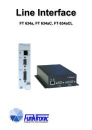
There are two housing versions of the <strong>Line</strong> <strong>Interface</strong><br />
<strong>FT</strong><strong>634</strong>. One in a black box and one in a 19 inch box.<br />
The <strong>FT</strong><strong>634</strong> is used for higher distances between<br />
control head and radio over an own or rented 2-<br />
or 4 wire.<br />
The <strong>FT</strong><strong>634</strong> is approved by TBR 15 and TBR 17.<br />
All audio signals are coupled via transformers.<br />
Standard version <strong>FT</strong><strong>634</strong><br />
To connect a control head or a radio there is PTT in/<br />
output, the audio in/output and supply contact. On the<br />
other side you connect the two- or four wire.<br />
Micro controller version <strong>FT</strong><strong>634</strong>C<br />
Additionally there are four digital outputs. For example<br />
it can be used for channel switching.<br />
The 19 inch version has 6 digital outputs and 6<br />
digital inputs.<br />
Micro controller version <strong>FT</strong><strong>634</strong><strong>CL</strong><br />
Additionally the line is watched of disconnect failure.<br />
Squelch/PTT input (<strong>FT</strong> <strong>634</strong> C/<strong>CL</strong>)<br />
The logic input of squelch/PTT is set in register 01<br />
on 3rd digit.<br />
Registers 01<br />
3. digit SQL/PTT input active, if<br />
0 = LOW ( 3V)<br />
Furthermore, one can configure Jumper JP10, whether<br />
the output of the radio/controlhead connected at the<br />
SQL/PTT input<br />
- also the logical HIGH actively switches or<br />
- only the logical LOW level actively to GND<br />
can switch<br />
(for example with an Open-Collector to GND)<br />
In the more final case an internal Pull-Up-Resistor<br />
is connected. See also section configuration of the<br />
Jumper.<br />
Jumper JP10<br />
HIGH of the SQL/PTT input switched through<br />
1 = active voltage (> 3 V)<br />
2 = keep open (Open-Collector)<br />
Kompetent für Elektroniksysteme<br />
<strong>Line</strong> <strong>Interface</strong> <strong>FT</strong><strong>634</strong> / <strong>FT</strong><strong>634</strong>C / <strong>FT</strong><strong>634</strong><strong>CL</strong><br />
- 2 -<br />
Transmitter control/carrier display (<strong>FT</strong><strong>634</strong>)<br />
The Transmitter control/carrier display (PTT/SQLoutput)<br />
switches on, as soon as from the AC-<strong>Line</strong> the<br />
pilot-tone (3300 Hz) is received.<br />
That <strong>FT</strong> <strong>634</strong> switches the TX/SQL-output through a<br />
potential-free relay as a result.<br />
Transmitter control/carrier display (<strong>FT</strong><strong>634</strong> C/<strong>CL</strong>)<br />
The Transmitter control/carrier display (PTT/SQLoutput)<br />
switches on, as soon as either from the<br />
AC-<strong>Line</strong> the pilot-tone (3300 Hz) or an audio signal<br />
(Audio-Squelch) is received.<br />
In 2 wire mode/simplex the Squelch/PTT input must<br />
not be activated, since his function priority has sets<br />
the Audio-Squelch out of order and puts down the<br />
pilot-tone.<br />
Register 01<br />
1. digit PTT/SQL-output switches through:<br />
0 = pilot tone decoding (2 wire/simplex)<br />
{not with active Squelch-/PTT input!}<br />
1 = pilot tone decoding (4 wire/duplex)<br />
{always!}<br />
2 = audio squelch (2 wire/simplex)<br />
{not with active Squelch-/PTT input!}<br />
3 = audio-squelch (4 wire/duplex)<br />
{always!}<br />
The <strong>FT</strong><strong>634</strong>C/<strong>CL</strong> switches the PTT/SQL output through<br />
a potential-free relay as a result.<br />
The audio squelch mode is only for the application<br />
as controlhead interface, to recommend, since a TX<br />
switching on is normally too uncertain over audio<br />
squelch.<br />
ft<strong>634</strong>eng (20.03.02)
Samples how to connect and to program<br />
The programming of the <strong>FT</strong><strong>634</strong> has to be according to the application.<br />
The following considerations should be done:<br />
Major 5<br />
EE-Reg 33 = 00046<br />
Kompetent für Elektroniksysteme<br />
- <strong>FT</strong><strong>634</strong> connected to the control head or to the radio<br />
- Channel remote control necessary?<br />
- <strong>Line</strong> watching necessary?<br />
- AC <strong>Line</strong> two or four wire, simplex or duplex?<br />
- Opposite a <strong>FT</strong><strong>634</strong> or a controlhead (for example major 3,4,5)?<br />
In the following examples the most important EEPROM registers 01, 05, 08 and 12 are listed.<br />
Hint: x marked digits are without importance or depents on customer application.<br />
Sample 1: Controlhead Major 5, opposite a one channel radio<br />
Sample 2: Controlhead Major 5, opposite a multichannel radio<br />
Major 5<br />
EE-Reg 33 = 00046<br />
EE-Reg 28 = x6x0x<br />
Major 6<br />
<strong>FT</strong><strong>634</strong> C<br />
EE-Reg 01 = 2101<br />
EE-Reg 05 = EEEx<br />
EE-Reg 08 = xxxx<br />
EE-Reg 12 = 0xxx<br />
2 wire<br />
2 wire<br />
Sample 3: Controlhead Major 6, opposite a one channel radio<br />
2 wire<br />
- 3 -<br />
<strong>FT</strong><strong>634</strong><br />
<strong>FT</strong><strong>634</strong> C<br />
EE-Reg 01 = 0100<br />
EE-Reg 05 = BCDx<br />
EE-Reg 08 = 020x<br />
EE-Reg 12 = 0xxx<br />
<strong>FT</strong><strong>634</strong><br />
Radio<br />
1 channel<br />
Radio<br />
multichannel<br />
SQL:<br />
LOW active (GND)<br />
Channelbits:<br />
HIGH active,<br />
binary - 1<br />
Radio<br />
1 channel<br />
Attention: No transmission of true carrier status<br />
possible, only audio squelch on <strong>FT</strong><strong>634</strong>C left side!<br />
ft<strong>634</strong>eng (20.03.02)
Sample 4: Controlhead Major 6, opposite a 1 channel radio, true transmission of carrier status<br />
Major 6<br />
Sample 6: Controlhead Major 6 on multichannel radio<br />
Major 6<br />
EE-Reg x65 = BCDFF<br />
EE-Reg x66 = 0xxxx<br />
Kompetent für Elektroniksysteme<br />
<strong>FT</strong><strong>634</strong> C<br />
EE-Reg 01 = 0001<br />
EE-Reg 05 = EEEx<br />
EE-Reg 08 = xxxx<br />
EE-Reg 12 = 0xxx<br />
- 4 -<br />
<strong>FT</strong><strong>634</strong> C<br />
EE-Reg 01 = 0101<br />
EE-Reg 05 = BCDx<br />
EE-Reg 08 = 132x<br />
EE-Reg 12 = 0xxx<br />
Sample 7: Controlhead Major 6, opposite a multichannel radio, with option line watching<br />
Major 6<br />
EE-Reg x65 = BCDFF<br />
EE-Reg x66 = 0xxxx<br />
<strong>FT</strong><strong>634</strong> C<br />
EE-Reg 01 = 0001<br />
EE-Reg 05 = EEEx<br />
EE-Reg 08 = xxxx<br />
EE-Reg 12 = 0xxx<br />
Sample 5: Controlhead Major BOS 2, opposite a full duplex radio<br />
Major BOS 2<br />
<strong>FT</strong><strong>634</strong> C<br />
EE-Reg 01 = 1211<br />
EE-Reg 05 = EEEx<br />
EE-Reg 08 = xxxx<br />
EE-Reg 12 = 0xxx<br />
<strong>FT</strong><strong>634</strong> <strong>CL</strong><br />
EE-Reg 01 = 0001<br />
EE-Reg 05 = EEEx<br />
EE-Reg 08 = xxxx<br />
EE-Reg 12 = 1001<br />
2 wire<br />
4 wire<br />
2 wire<br />
2 wire<br />
<strong>FT</strong><strong>634</strong> C<br />
EE-Reg 01 = 0101<br />
EE-Reg 05 = EEEx<br />
EE-Reg 08 = xxxx<br />
EE-Reg 12 = 0xxx<br />
<strong>FT</strong><strong>634</strong> C<br />
EE-Reg 01 = 1211<br />
EE-Reg 05 = EEEx<br />
EE-Reg 08 = xxxx<br />
EE-Reg 12 = 0xxx<br />
<strong>FT</strong><strong>634</strong> <strong>CL</strong><br />
EE-Reg 01 = 0111<br />
EE-Reg 05 = BCDx<br />
EE-Reg 08 = 132x<br />
EE-Reg 12 = 2101<br />
Radio<br />
1 channel<br />
Squelch<br />
LOW active<br />
Full duplex<br />
radio<br />
Squelch<br />
HIGH active<br />
Multichannel<br />
radio<br />
Squelch<br />
LOW active<br />
Channelbits:<br />
LOW active<br />
binary<br />
Multichannel<br />
radio<br />
Squelch<br />
HIGH active<br />
Channelbits:<br />
LOW active,<br />
binary<br />
ft<strong>634</strong>eng (20.03.02)
Service Program, only with <strong>FT</strong><strong>634</strong>C and <strong>FT</strong><strong>634</strong><strong>CL</strong><br />
The <strong>FT</strong><strong>634</strong>C/<strong>CL</strong> have one RS232 interface (TTL, dont connect direct to PC) with following specification:<br />
Kompetent für Elektroniksysteme<br />
4800 bauds, 1 start bit, 8 data bits, no parity, 1 stop bit<br />
The connections for the RS232 interface is either inside of the case on the 3-pin male connector ST4 or<br />
on the 64-pin DIN41612 connector ST1.<br />
For programming you must use the interface RS232Ad1.<br />
If the terminal is connected, you have access on the service program and some commands, like for<br />
example:<br />
- programming the EEPROM<br />
- transmitting of tone sequence<br />
- service mode analog switch<br />
- level tone transmitting<br />
To start the service program, you simply enter at the terminal or , .<br />
Programming mode EEPROM<br />
To program a address with the content , do the following:<br />
1) Start service program with or ,<br />
2) Read register --> put in ,<br />
=> At the screen appears: Register xx: wwww><br />
3) Write register --> put in ,<br />
xx = number of register<br />
yyyy = value of register<br />
You find a list of all registers in the following section.<br />
Register encoding for<br />
00 Impedance of the AC line<br />
1. digit 0 = high input impedance<br />
1 = input impedance 600 ohms<br />
2. digit 0 = high output impedance<br />
1 = output impedance 600 ohms<br />
- 5 -<br />
ft<strong>634</strong>eng (20.03.02)
Register encoding for<br />
01 1. digit, PTT/SQL switching<br />
0 = pilot tone evaluation (2 wire/simplex)<br />
{not with active SQL/PTT input!}<br />
1 = pilot tone evaluation (4 wire/duplex)<br />
{always!}<br />
2 = audio squelch (2 wire/simplex)<br />
{not with active SQL/PTT input!}<br />
3 = audio squelch (4 wire/duplex)<br />
{always!}<br />
2. digit, in silence switched through audio path<br />
0 = multi wire —> AC line,<br />
switched by pilot tone evaluation<br />
1 = AC line —> multi wire,<br />
switch by active squelch/PTT input<br />
2 = AC line —> multi wire, without toggle<br />
3. digit, squelch/PTT input active if<br />
0 = LOW ( 3V)<br />
4. digit, if squelch/PTT input active then<br />
0 = pilot tone not transmitted to the AC line<br />
1 = pilot tone transmitted to the AC line<br />
05 5 tone to switch the output, EEEE = disable<br />
06 last set digital outputs<br />
07 5 tone for digital inputs<br />
08 configurations for channel interface<br />
1. digit, output logic<br />
0 = normally (1 = HIGH)<br />
1 = inverts (1 = LOW)<br />
2. digit, bit-interpretation<br />
2 = binary-1<br />
3 = binary<br />
3. digit, acknowledge mode (1. and 2. digit of telegram)<br />
0 = normally, without pilot tone<br />
1 = swaped, without pilot tone<br />
2 = swaped, with pilot tone<br />
10 Tone sequence for line watching<br />
11 1. digit, master cycle time, n * 10 sec<br />
2. digit, master cycle time, n * 1 sec<br />
3. digit, slave cycle time, n * 10 sec<br />
4. digit, slave cycle time, n * 1 sec<br />
12 1. digit, line watching<br />
0 = off<br />
1 = device is master<br />
2 = device is slave<br />
2. digit, line watching with pilot tone 1=on, 0=off<br />
3. digit, line failure indicated by<br />
Bit 3 = ---<br />
Bit 2 =---<br />
Bit 1 = digital output 5<br />
Bit 0 = digital output 4<br />
4. digit, line failure indicated by<br />
Bit 3 = digital output 3<br />
Bit 2 = digital output 2<br />
Bit 1 = digital output 1<br />
Bit 0 = digital output 0<br />
Kompetent für Elektroniksysteme<br />
- 6 -<br />
ft<strong>634</strong>eng (20.03.02)
Adjustment<br />
All <strong>FT</strong><strong>634</strong> delivered are on default levels. Please adjust the levels to your radio or controlhead. Also adjust<br />
the incoming level of the AC line. Follow the steps below.<br />
1) Adjustment of AC line input:<br />
Kompetent für Elektroniksysteme<br />
a) put in 1000 Hz at the pre-determined level into the ac line<br />
b) measuring on the testpoints MP1 and MP0 (GND) is normaly -12 dBm<br />
c) turn R35 anticlockwise to the end<br />
d) adjust the level on R30<br />
e) put in 3400 Hz at the pre-determined level into the ac line<br />
f) adjust the frequency response on R35 to - 12 dBm, the max. gain for higher frequencies is 12 dB<br />
2) Adjustment of the audio output to the radio or controlhead:<br />
a) put in 1000 Hz at the pre-determined level into the ac line<br />
b) put in jumper JP9 to position 2<br />
c) connect the radio or controlhead according to your application<br />
d) adjust R74 to get nomonally deviation<br />
e) put jumper JP9 back to position 1<br />
3) Adjustment of the audio input coming from the radio or controlhead<br />
a) put in 1000 Hz at the pre-determined level to get maximum deviation<br />
b) measuring on the testpoints MP2 and MP0 (GND) is normaly -12 dBm<br />
c) adjust the level on R79<br />
- 7 -<br />
ft<strong>634</strong>eng (20.03.02)
Configuration of the jumpers<br />
1a) Configuration 4 wire mode: Set the jumpers JP1-JP8 accordingly<br />
ST3 ST2<br />
1b) Configuration 2 wire mode: Set the jumpers JP1-JP8 accordingly (default on delivery)<br />
2) Configuration of squelch/ptt input (jumper JP10):<br />
Kompetent für Elektroniksysteme<br />
ST3 ST2<br />
2 1<br />
2 1<br />
2 1<br />
2 1<br />
JP9<br />
JP10<br />
JP9<br />
JP10<br />
LED1<br />
LED2<br />
LED1<br />
LED2<br />
2 1<br />
2 1<br />
2 1<br />
2 1<br />
2 1<br />
2 1<br />
2 1<br />
2 1<br />
2 1<br />
2 1<br />
2 1<br />
2 1<br />
2 1<br />
2 1<br />
JP7<br />
JP6<br />
JP5<br />
JP4<br />
JP3<br />
JP2<br />
JP1<br />
JP7<br />
JP6<br />
JP5<br />
JP4<br />
JP3<br />
JP2<br />
JP1<br />
R35<br />
R30<br />
R35<br />
R30<br />
2 1<br />
2 1<br />
2 1<br />
2 1<br />
JP9<br />
JP10<br />
JP9<br />
JP10<br />
R82<br />
R82<br />
a) Set the jumper JP10 to position 2 for squelch/PTT active low.<br />
b) Set the jumper JP10 to positon 1 for squelch/PTT active high.<br />
- 8 -<br />
1 2<br />
MP2<br />
MP1<br />
MP0<br />
1 2<br />
MP2<br />
MP1<br />
MP0<br />
R79<br />
JP8<br />
R74<br />
R79<br />
JP8<br />
R74<br />
F1<br />
F1<br />
RXD<br />
GND<br />
TXD<br />
RXD<br />
GND<br />
TXD<br />
ST4<br />
ST4<br />
1<br />
2<br />
3<br />
1<br />
2<br />
3<br />
ST1<br />
ST1<br />
ft<strong>634</strong>eng (20.03.02)
Connectors <strong>FT</strong> <strong>634</strong>, <strong>FT</strong><strong>634</strong>C, <strong>FT</strong><strong>634</strong><strong>CL</strong><br />
AC line Standard Box: Connector ST2 (9-pin D-Sub)<br />
19" Box: Connector ST1 (64-pin DIN41612)<br />
Standard 19"<br />
pin/No. pin/No.<br />
1 6c Audio In/Out a<br />
5 7c Audio In/Out b<br />
Kompetent für Elektroniksysteme<br />
2 wire AC line<br />
1 6c Audio Out a<br />
6 5c Audio Out b 4 wire AC line<br />
5 7c Audio In a<br />
9 4c Audio In b<br />
Connector for radio Standard Box: Connector ST3 (15-pin D-Sub)<br />
19" Box: Connector ST1 (64-pin DIN41612)<br />
Standard 19"<br />
pin/No. pin/No.<br />
1+9 1a+c +12 V supply<br />
8+15 32a+c GND<br />
4 16c Audio Out a (TX)<br />
5 15c Audio Out b (TX)<br />
11 10c Audio In a (RX)<br />
12 11c Audio In b (RX)<br />
2 24c PTT relais contact a<br />
3 24a PTT relais contact b<br />
Additional ports, only with version <strong>FT</strong><strong>634</strong>C and <strong>FT</strong><strong>634</strong><strong>CL</strong><br />
10 26a squelch input<br />
6 9a digital out 0<br />
7 10a digital out 1<br />
13 11a digital out 2<br />
14 12a digital out 3<br />
-- 13a digital out 4<br />
-- 14a digital out 5<br />
-- 3a digital in 0<br />
-- 4a digital in 1<br />
-- 5a digital in 2<br />
-- 6a digital in 3<br />
-- 7a digital in 4<br />
-- 8a digital in 5<br />
Connector RS232 Standard Box: Connector ST4 (3-pin)<br />
19" Box: Connector ST1 (64-pin DIN41612)<br />
Standard 19"<br />
pin/No. pin/No.<br />
1 20a RXD Attention:<br />
2 21a GND only TTL level, do not connect direct to PC,<br />
3 22a TXD use interface RS232AD1, Order No. 901900<br />
- 9 -<br />
ft<strong>634</strong>eng (20.03.02)
Kompetent für Elektroniksysteme<br />
Technical Data<br />
Supply<br />
Voltage + 12 V/DC - 8% + 40%<br />
Supply current (<strong>FT</strong> <strong>634</strong>) 60 mA<br />
Supply current (<strong>FT</strong> <strong>634</strong> C/<strong>CL</strong>) 110 mA<br />
Fuse 500 mA<br />
Input level AC line<br />
Factory adjusted to - 10 dBm (245 mV)<br />
Adjusting range (R30) - 30 dBm to - 6 dBm (25 to 390 mV)<br />
Input impedance (normaly) 600 Ohm<br />
Input impedance (high) 20/40 kOhm (2 wire/4 wire)<br />
Output level AC line - 10 dBm (245 mV)<br />
Output impedance 600 Ohm<br />
Input level radio/controlhead<br />
Factory adjusted to + 3 dBm (1094 mV)<br />
Adjusting range (R79) - 24 dBm to + 6 dBm (49 to 1546 mV)<br />
Input impedance 600 Ohm<br />
Output level radio/controlhead<br />
Factory adjusted to - 17 dBm (109 mV)<br />
Adjusting range (R74) - 30 dBm to + 5 dBm (25 to 1377 mV)<br />
Output impedance 600 Ohm<br />
Pilot tone frequency f c = 3300 Hz<br />
Pilot tone notch filter<br />
Absorption > 50 dB<br />
Weight<br />
Standard version 550 g<br />
19 Inch Box 530 g<br />
Dimensions<br />
Standard version 130 x 46 x 180 mm<br />
19 Inch Box 35 x 186 x 128 mm<br />
- 10 -<br />
ft<strong>634</strong>eng (20.03.02)


