Major 3 TRC - Funktronic
Major 3 TRC - Funktronic
Major 3 TRC - Funktronic

You also want an ePaper? Increase the reach of your titles
YUMPU automatically turns print PDFs into web optimized ePapers that Google loves.
<strong>Major</strong> 3 <strong>TRC</strong><br />
English Version 1.0<br />
Kompetent für Elektroniksysteme
Table of Contents<br />
Section Page<br />
Display and Control Elements 4<br />
General Operating Instructions 5<br />
Busy Indicator and carrier input 5<br />
Loudspeaker and indicator 5<br />
Call Handling 6<br />
Calling Radio Subscriber 6<br />
Short Call Numbers 6<br />
Group Call 6<br />
Transmitting a tone sequence with analog input 6<br />
Call from Radio Subscriber 6<br />
Input the status code 7<br />
Transmitting a call by pushing the PTT 7<br />
Transmitting a call by releasing the PTT 7<br />
5-Tone Sequence Encoder 7<br />
Precoding 7<br />
Call with ID code 7<br />
Transmitting call with status 7<br />
Receiving of calls 8<br />
Decoder 1 8<br />
Bell Tone 8<br />
Alarm Switching Output 8<br />
Acknowledgement 8<br />
Group Call Decoder 8<br />
Conference Call Decoder 9<br />
Emergency Decoder 9<br />
ID-Code Memory 9<br />
Key Tones 9<br />
Memory updating 10<br />
Tone length encoder 10<br />
Tone length decoder 10<br />
Tone length of the emergency tone (decoder) 10<br />
Tone Systems 10<br />
Tone Table 11<br />
Transmitter keying 11<br />
TX time out timer 11<br />
Transmitter prerunning time 11<br />
PTT button blocking 11<br />
Pilot tone and DC remote control 12<br />
Channel switching (<strong>TRC</strong>) 12<br />
Tone/Channel table for <strong>TRC</strong> 12<br />
FFSK mode (option) 12<br />
Telegram Structure 12<br />
FFSK Encoder 13<br />
Operating Mode Reference 13<br />
Limit Number 13<br />
Rhomb 14<br />
FFSK Emergency Call 14<br />
FFSK Decoder 14<br />
FFSK Acknowledgement 14<br />
Setup Mode 15<br />
Setup Menu 15<br />
EEPROM Programming Mode 15<br />
Registers 16-19<br />
Service mode analog switches 20<br />
- 2 -<br />
Kompetent für Elektroniksysteme
Service mode potentiometer 20<br />
Transmit levelling tones 20<br />
Adjustment 20<br />
Connector 21<br />
Technical Data 22<br />
Kompetent für Elektroniksysteme<br />
- 3 -<br />
m3trc_eng (08.01.02)
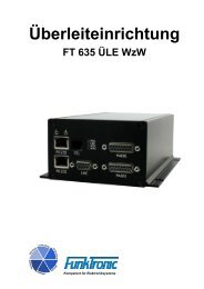
Display and Control Elements<br />
8<br />
7<br />
13<br />
1 - PTT Indicator<br />
2 - Loudspeaker indicator<br />
3 - Busy indicator<br />
4 - PTT key<br />
5 - Call button<br />
6 - Short call button, status key<br />
7 - Loudspeaker key<br />
8 - Loudspeaker volume key<br />
9 - Function key and channel selection<br />
10 - Function key and ID-Code memory<br />
11 - LED Display<br />
12 - Microphone<br />
13 - Loudspeaker<br />
6<br />
3<br />
5<br />
2<br />
4<br />
9<br />
1<br />
- 4 -<br />
12<br />
11<br />
Rear view <strong>Major</strong> 3<br />
10<br />
25-pol connector male<br />
220 V/AC connector<br />
Power switch<br />
Kompetent für Elektroniksysteme
<strong>Major</strong> 3 <strong>TRC</strong><br />
General Operating Instructions<br />
Kompetent für Elektroniksysteme<br />
- 5 -<br />
m3trc_eng (08.01.02)<br />
The <strong>Major</strong> 3 is controlled by a micro processor. It is used to control radio systems. To program<br />
the <strong>Major</strong> 3 you use easily the keyboard.<br />
There are two main versions of <strong>Major</strong> 3. One for use with 12 V DC main power and one with<br />
integrated 230 V AC power supply.<br />
On the rear side is 25-pin connector. This is for connecting squelch input, ptt output, audio in/output,<br />
5 plus 1 digital outputs. You can also connect the DC power to this.<br />
The <strong>Major</strong> 3 with option FFSK/RS232 has an RS232 Interface. You can use it to program the <strong>Major</strong><br />
3 or connect a terminal for special purposes.<br />
Only the <strong>Major</strong> 3 for 230 V AC has an power switch on the rear side. After switching on the display<br />
shows for one sec. . Then the cursor flashes for input.<br />
Before first use of <strong>Major</strong> 3, you have to adjust audio levels to the radio.<br />
Busy Indicator and carrier input<br />
The busy indicator and as well the carrier input is programmed with EEPROM register 053 on 1.<br />
position. Any voltage from 0 to 2 volt is detected as low and a voltage from 3 to 12 volt as high. If you<br />
have an 2-wire connection you can use the carrier input to transmit a programmed tone sequence. In<br />
case of a two-wire system the busy indicator is controlled by voice activity.<br />
Register 053<br />
1. position busy indicator on when<br />
0 = carrier input < 2V<br />
1 = carrier input > 3V<br />
2 = audio squelch, 2-wire connection<br />
3 = audio squelch, 2-wire connection, transmitting tone sequence when<br />
carrier input is true<br />
Loudspeaker indicator<br />
Is switched on if the loudspeaker is open. The indicator flashes if an incoming call is detected. In<br />
this case the loudspeaker is also switched active.<br />
Loudspeaker<br />
To change the volume push the button loudspeaker key. The display shows and now you<br />
can enter a new value from 0 to 9.<br />
You can switch on and off the loudspeaker by pushing the loudspeaker key. The loudspeaker is also<br />
active after pushing the PTT, after transmitting a call or if a incoming call is detected.<br />
The loudspeaker is switch of manually by the loudspeaker key or automatically with a programmable<br />
timer.
Register 050 loudspeaker mode and timer<br />
1. position LS-Timer sec. * 100<br />
2. position LS-Timer sec. * 10<br />
3. position LS-Timer sec. * 1<br />
4. position 0 = loudspeaker controlled mode<br />
1 = loudspeaker always open<br />
Call Handling<br />
You can talk to the radio subscriber by pushing the PTT. After releasing the PTT button you will<br />
hear the radio subscriber through the loudspeaker. Normally, after call termination, the loudspeaker<br />
is switched off by the loudspeaker key.<br />
Calling Radio Subscriber<br />
At first, the call number is entered via the key pad. The input is complete when the number<br />
is right-aligned on the display. None of the input positions is flashing any longer. The call is<br />
transmitted by pressing the call button.<br />
Short Call Numbers<br />
The <strong>Major</strong> 3 is provided with 10 programmable short call numbers. By pressing the (Z) key and<br />
the following input of a digit between 0 and 9, a precoded call is transmitted. These short call<br />
numbers are coded in registers 000 to 009.<br />
Group Call<br />
In order to be able to use the 5-tone sequence call system without any restrictions, tone 'A' should<br />
be used as group calling tone. Tone 'A' is entered by the (*) key. The group calling tone may be<br />
placed at any position. The call starts by pressing the call button.<br />
Transmitting a tone sequence with analog input<br />
By switching the analog input to ground the 5-tone sequence in register 011 is transmitted. This<br />
function is activated in register 054.<br />
Register 3. position analog input<br />
0 = no function<br />
1 = transmitting 5-tone<br />
Transmitting a tone sequence with carrier input<br />
By switching the carrier input to ground the 5-tone sequence in register 012 is transmitted. This<br />
function is activated in register 053. See section Busy Indicator and carrier input.<br />
Call from Radio Subscriber<br />
An incoming call is registered by a bell tone. The loudspeaker is switched on and the loudspeaker<br />
LED flashes.<br />
- 6 -<br />
Kompetent für Elektroniksysteme
Input the status code<br />
Kompetent für Elektroniksysteme<br />
- 7 -<br />
m3trc_eng (08.01.02)<br />
If you hold down the (Z) key for a moment you enter the status mode. Now you can enter a<br />
one or two digit status.<br />
Transmitting a call by pushing the PTT<br />
You can transmit a 5-tone or FFSK code by pushing the PTT. The code from register 015 is used.<br />
Register 053<br />
3. position 0 = no transmission<br />
1 = FFSK code transmitted<br />
2 = 5-tone code transmitted<br />
Transmitting a call by releasing the PTT<br />
You can transmit a 5-tone or single tone (roger peep) code by releasing the PTT. The 5-tone<br />
code from register 015 is used.<br />
Register 053<br />
4. position 0 = no transmission<br />
1 = roger peep 2800 Hz<br />
2 = 5-tone code + status transmitted<br />
2 = 5-tone code + status + roger peep transmitted<br />
5-Tone Sequence Encoder<br />
Precoding<br />
The 5-tone sequence encoder is configured according to the application requirements and as well<br />
for comfortable operation. Logically, you will permanently code those positions which should not be<br />
entered via the key pad. The permanently coded tones can be placed at any position of the tone<br />
sequence. Use F for variable positions. For example, it is possible to permanently code positions 1,<br />
3, and 5. In this case only position 2 and 4 are entered via the key pad. The positions to be freely<br />
entered are always displayed right aligned. If two subsequent tones are identical, the repeat tone<br />
is automatically used at the correct position. The 5-tone sequence encoder is coded in register 010.<br />
See section EEPROM 1 Programming Mode.<br />
Call with ID code<br />
The ID code is programmed in register 015. Normally the ID code is programmed same as decoder<br />
1. The sequence of ID code and call code is programmed in register 053.<br />
Register 053 2. position 0 = no code<br />
1 = call code + ID code (double sequence)<br />
2 = ID code + call code (double sequence)<br />
3 = call code + ID code (6-tone sequence)<br />
4 = call code + ID code (7-Tone sequence)<br />
5 = call code + ID code (8-Tone sequence)<br />
Transmitting call with status<br />
The status can be one or two digit. It is added on the end of the tone sequence.<br />
Register 054 1. position 0 = no status<br />
1 = status one digit<br />
2 = status two digit
Receiving of calls<br />
The <strong>Major</strong> 3 has 10 decoders. They are coded in registers 020 to 029. If you don't need a decoder,<br />
put in an F on first position. You can also program different modes in the registers 030 to 039.<br />
The following modes are possible.<br />
- managing of double sequences<br />
- managing of tone sequences with more than 5 tones<br />
- display of received ID codes<br />
- bell tone<br />
- on time of emergency contact<br />
- acknowledgement<br />
- loudspeaker mode<br />
Decoder 1<br />
The Decoder 1 is coded in register 020. Every tone sequence is compared with the decoder 1 coding<br />
and in case of positions being coded with 'F', every tone of the tone system will be accepted. If the<br />
tone sequence has been identified as correct, the loudspeaker is switched on, the loudspeaker lamp<br />
flashes, and if you are not operating with double sequences, the acknowledgement is transmitted.<br />
After that, the bell tone is activated. If you operate with double sequences, the acknowledgement<br />
delay is at most one second. Any further tone sequence check, for example by decoder 2 or the<br />
conference call decoder, is not performed.<br />
Bell Tone<br />
The bell tone volume is according to the basic programmed volume. You have the choice of<br />
10 different bell tones (1 to A). If no bell tone is desired, a '0' has to be programmed at<br />
this position.<br />
Alarm Switching Output<br />
After successful evaluation the bell tone is generated and the alarm contact is switched for n*1<br />
seconds. The alarm time is programmable for each decoder. The alarm contact time is programmed<br />
in one-second intervals in registers 030 to 039 3. position.<br />
Acknowledgement<br />
The automatic acknowledgement after a selective call can operate in different ways. The<br />
acknowledgement mode is programmed at position 4 of register 030 as follows:<br />
0 = no acknowledgement<br />
1 = standard acknowledgement (from register 017)<br />
2 = acknowledgement with a single tone of 600 Hz for 300 msec<br />
3 = acknowledgement with a tone sequence from register 015 (ID-code)<br />
4 = acknowledgement with the identification last received<br />
5 = additionally standard acknowledgement (from register 017), used for FFSK<br />
Group Call Decoder<br />
The group call decoder for tone A or 0 can be programmed for each of the ten decoders. Program<br />
tone A or 0 on the position you want. Don't forget to block acknowledgement.<br />
- 8 -<br />
Kompetent für Elektroniksysteme
Conference Call Decoder<br />
Kompetent für Elektroniksysteme<br />
- 9 -<br />
m3trc_eng (08.01.02)<br />
The conference call decoder detects a tone of at least one second duration. After detection the<br />
loudspeaker is switched on, the loudspeaker lamp flashes, and the bell tone is activated. No<br />
acknowledgement is transmitted. The conference call tone frequency is coded at position 1 of<br />
register 044 with the corresponding digit of the tone system ('0' ... 'E') . If this decoder is not<br />
required, please code an 'F' at that position.<br />
Register 044 conference call decoder<br />
1. position frequency of conference call (F for off)<br />
2. position bell tone<br />
0 = no bell tone<br />
1 = bell tone type 1<br />
2 = bell tone type 2<br />
.<br />
.<br />
.<br />
A = bell tone type 9<br />
3. position n * sec. emergency output on<br />
4. position n/a<br />
5. position loudspeaker<br />
0 = always off<br />
1 = on if call detected<br />
Emergency Decoder<br />
The emergency call decoder is coded in register 046. If this decoder is not required, please code<br />
an 'F' at the first position of the tone sequence. The read in 5-tone sequence is compared with the<br />
emergency coding. From the second up to the fifth position those positions being coded with 'F' will<br />
accept all tones of the tone system. The 5 tones has to be followed by a 6th tone. This tone is coded<br />
in register 046 on 5. position. In case of successful decoding the loudspeaker is switched on. The<br />
emergency output is activated. As long as an emergency call is indicated on the display, the key<br />
pad is blocked with exception of the PTT button.<br />
ID-Code Memory<br />
The ID-code memory can be configured so that it is optimal adapted to current use. Up to 16<br />
ID-codes can be stored. If all memory positions are engaged, the memory is updated by deleting the<br />
oldest ID-code. The stored ID-codes can be scrolled through by pressing the (#) key in such<br />
way that the ID-code stored last is displayed by the first key pressing. The currently displayed<br />
ID-code can be deleted from the memory by pressing the (#) key longer. If the "FIFO" function is<br />
switched on, always the oldest number is shown on the display by pressing the (#) key and only<br />
after deleting this ID-code the next ID-code follows. The "FIFO" function is programmed at the<br />
second position of register 043. The ID-code memory can be used for single or double sequences<br />
as well as for 6, 7 and 8 tone sequences.<br />
Key Tones<br />
The key tones are coded in register 016. The coding of these tones selects the ID-codes which are<br />
stored, and determines the digits to be displayed. Those positions where every tone is allowed and<br />
which are displayed later on, has to be coded with 'F'.
Memory updating<br />
Before an ID-code is accepted by the ID-code memory, the software checks if the same ID-code<br />
has already been stored in the memory. If the ID-code has already been stored and if the updating<br />
has not been activated, the ID-code is rejected. If the updating is switched on, the ID-code at<br />
the old position is deleted in order to be stored again at the first position. Therefore, the ID-code<br />
memory is always arranged in chronological order. The memory updating is programmed at<br />
position 1 of register 021.<br />
Tone length encoder<br />
The length of the first tone is defined at positions 1 and 2 of register 042. The length of the other<br />
tones can be adjusted at position 3 of register 042. The value can be switched in 10 msec intervals.<br />
The tone length of the first tone can also deviate from the other tones.<br />
Tone length decoder<br />
In case of tone identification a tolerance has to be added. This ensures that even inexact 5-tone<br />
telegrams are evaluated correctly. The minimum tone length is programmed in register 040 at<br />
position 4 and 5. The maximum tone length of the first tone is programmed in register 040 at position<br />
1 to 3. The maximum tone length of the others is programmed in register 041 at position 1 to 3.<br />
The values are adjustable in 5 msec steps.<br />
Tone length of the emergency tone (decoder)<br />
The emergency tone is the 6th tone. The minimum length is defined in register 045 at position 4<br />
and 5. The maximum is programmed in register 045 an position 1 to 3. The values are adjustable<br />
in 5 msec steps.<br />
Tone Systems<br />
The <strong>Major</strong> 3 can be configured for various tone systems without any hardware modification. The<br />
tone system is selected at position 5 of register 046. When a tone system is selected, the tone<br />
length is not automatically adjusted. Therefore, if a change is made from ZVEI 1 to CCIR, the<br />
tone length has to be redefined as well.<br />
Register 041 5. position 0 = ZVEI 1<br />
1 = CCIR<br />
2 = ZVEI 2<br />
3 = EEA<br />
4 = ZVEI 3<br />
- 10 -<br />
Kompetent für Elektroniksysteme
Tone Table<br />
Tone ZVEI 1 CCIR ZVEI 2 EEA ZVEI 3<br />
0 2400 Hz 1981 Hz 2400 Hz 1981 Hz 2200 Hz<br />
1 1060 Hz 1124 Hz 1060 Hz 1124 Hz 970 Hz<br />
2 1160 Hz 1197 Hz 1160 Hz 1197 Hz 1060 Hz<br />
3 1270 Hz 1275 Hz 1270 Hz 1275 Hz 1160 Hz<br />
4 1400 Hz 1358 Hz 1400 Hz 1358 Hz 1270 Hz<br />
5 1530 Hz 1446 Hz 1530 Hz 1446 Hz 1400 Hz<br />
6 1670 Hz 1540 Hz 1670 Hz 1540 Hz 1530 Hz<br />
7 1830 Hz 1640 Hz 1830 Hz 1640 Hz 1670 Hz<br />
8 2000 Hz 1747 Hz 2000 Hz 1747 Hz 1830 Hz<br />
9 2200 Hz 1860 Hz 2200 Hz 1860 Hz 2000 Hz<br />
A 2800 Hz 2400 Hz 886 Hz 1055 Hz 886 Hz<br />
B 810 Hz 930 Hz 810 Hz 930 Hz 810 Hz<br />
C 970 Hz 2247 Hz 740 Hz 2247 Hz 740 Hz<br />
D 886 Hz 991 Hz 680 Hz 991 Hz 680 Hz<br />
E 2600 Hz 2110 Hz 970 Hz 2110 Hz 2400 Hz<br />
length<br />
min. 52.5 msec 75 msec 52.5 msec 30 msec 52.5 msec<br />
typ. 70 msec 100 msec 70 msec 40 msec 70 msec<br />
max. 87.5 msec 125 msec 87.5 msec 50 msec 87.5 msec<br />
Transmitter keying<br />
Kompetent für Elektroniksysteme<br />
- 11 -<br />
m3trc_eng (08.01.02)<br />
The transmitter can be keyed by the red PTT button on the key pad. The transmitter is keyed as long<br />
as the PTT button is pressed, except if the TX time out is exceeded. In the multi wire version it is<br />
controlled by an open collector output and in AC version by a pilot tone.<br />
TX time out timer<br />
The TX time out timer is programmed in one second intervals at positions 1 to 3 of register<br />
051. Values of '000' up to '255' are permitted. If the programmed value is '000', the TX time<br />
out timer is out of operation.<br />
Transmitter prerunning time<br />
The prerunning time is preceding every call before connecting the audio. It can be programmed<br />
in 10 msec intervals at positions 1 to 2 of register 052. The variable value can be defined freely<br />
between '00' and '99'.<br />
PTT button blocking<br />
The PTT button blocking is programmed at position 5 of register 052.<br />
0 = PTT button blocking is switched off<br />
1 = PTT button is blocked in case of sensed carrier
Pilot tone and DC remote control<br />
The remote control is configured in position 3 and 4 at register 052.<br />
Register 052<br />
Channel switching (<strong>TRC</strong>)<br />
3. position AC remote control<br />
0 = no AC remote control<br />
1 = AC remote control with pilot tone 3300 Hz<br />
2 = AC remote control with pilot tone 3000 Hz<br />
3 = AC remote control for Motorola <strong>TRC</strong> with guard tone 2100 Hz<br />
4. position level of pilot tone<br />
0 = 0 dBm<br />
1 = -10 dBm<br />
2 = 50 msec 0 dBm, then - 10 dBm<br />
To put in a channel, push the key (*) until the left digit flashes. The numbers from 1 to 8 are<br />
possible.<br />
Register 066 1. position 0 = channel switching off<br />
1 = channel switching on<br />
Tone/Channel table for <strong>TRC</strong><br />
Channel Frequency/Hz<br />
1 1950<br />
2 1850<br />
3 1750<br />
4 1650<br />
5 1350<br />
6 1250<br />
7 1150<br />
8 1050<br />
FFSK mode (option)<br />
The <strong>Major</strong> 3 can be used in combined networks if it is provided with FFSK option. In this case an<br />
FFSK modem operates simultaneously with the 5-tone modem. The <strong>Major</strong> 3 operates according<br />
to ZVEI recommendation.<br />
Telegram Structure<br />
The call telegram starts with an unmodulated carrier which has to be available at the receiver side<br />
for at least 25 msec. It is followed by telegram reload with a 16 bit 1/0 sequence and the block<br />
synchronization. For block synchronization a 15 bit "barker word" with a preceding '1' is used. The<br />
now following selective call number is built as decade. It always consists of 8 digits. The telegram is<br />
saved by an additional 8 bit redundancy.<br />
- 12 -<br />
Kompetent für Elektroniksysteme
FFSK Encoder<br />
Kompetent für Elektroniksysteme<br />
- 13 -<br />
m3trc_eng (08.01.02)<br />
While the 5-tone and the FFSK decoder are ready for detection simultaneously, it has to be<br />
decided for call transmission whether a 5-tone or FFSK telegram shall be transmitted. The<br />
<strong>Major</strong> 3 derives this selection from the call number and automatically transmits the call in the<br />
correct call mode.<br />
The 8-digit selective call number is arranged as follows:<br />
1. position fixed operating mode reference (BAK)<br />
2. position fixed status<br />
3. position fixed rhomb<br />
4 ... 5. position variable manufacturer reference<br />
6 ... 8. position variable Call code<br />
The encoder is configured according to the application requirements and as well for comfortable<br />
operation. Logically, you will permanently code those positions which should not be entered via<br />
the key pad. The permanently coded tones can be placed at any position of the manufacturer<br />
reference and call code. For example, it is possible to permanently code positions 4, 6, and 8. In<br />
this case only positions 5 and 7 are entered via the key pad. Usually, the first two or three digits<br />
are permanently coded. The positions to be freely entered are always displayed right aligned. The<br />
FFSK encoder is programmed in register 010.<br />
Operating Mode Reference<br />
The operating mode reference ("Betriebsartenkennzeichen" = BAK) is the criterion for different<br />
telegram forms:<br />
0 At disposal<br />
1 Q Call to mobile<br />
2 Q Call to master station<br />
3 Identification<br />
4 Acknowledgement<br />
5 Following telegram<br />
6 Q Break call<br />
7 Reserved<br />
8 Q Priority call<br />
9 Q Status report<br />
A Reserved<br />
B Reserved<br />
C Reserved<br />
D At disposal<br />
E At disposal<br />
F Emergency call<br />
BAKs marked with Q require an acknowledgement. In case of coding a '0', '2', '3' or 'F' every<br />
telegram is processed by the FFSK decoder.<br />
Limit Number<br />
The limit number is programmed at positions 1 to 3 of register 060. Call codes lower than the limit<br />
number are transmitted as 5-tone sequence; call codes higher or the same as the limit number<br />
are transmitted as FFSK telegram.
Rhomb<br />
The rhomb is programmed at position 5 of register 060. Application at disposal.<br />
FFSK Emergency Call<br />
If a FFSK telegram with status = emergency call is received, the loudspeaker is switched on, the<br />
loudspeaker lamp flashes, the emergency call ID-code is stored and flashes on the display. As<br />
long as an emergency call is displayed, the key pad is blocked (exception PTT). An emergency<br />
call can be deleted by pressing the (#) key.<br />
FFSK Decoder<br />
The decoder 1 to 10 are coded in registers 020 to 029. The telegram detected is compared with<br />
the decoder 1 coding and in case of positions being coded with 'F', any digit is accepted. If the<br />
FFSK telegram has been identified as correct, the loudspeaker is switched on, the loudspeaker<br />
lamp flashes, the FFSK acknowledgement is transmitted and the bell tone is started. No further<br />
telegram check will be performed.<br />
The decoder 2 is coded in register 007 (EEPROM 1). See section EEPROM 1 Programming Mode.<br />
The telegram detected is compared with the decoder 2 coding and in case of positions being coded<br />
with 'F', any digit is accepted. If the FFSK telegram has been identified as correct, the loudspeaker<br />
and the handset are switched on, the loudspeaker lamp flashes and the bell tone is started. No further<br />
telegram check will be performed. An acknowledgement is not transmitted.<br />
FFSK Acknowledgement<br />
After detection by decoder 1 the FFSK acknowledgement is transmitted. The acknowledgement<br />
is coded in register 017. If no acknowledgement is required, position 4 of register 030 ... 039<br />
is coded with '0'.<br />
Register 030 ... 039 4. position 0 = no acknowledgement<br />
1 = FFSK standard acknowledgement<br />
2 = single tone 600 Hz for 300 msec<br />
3 = ID code<br />
4 = received ID code<br />
5 = FFSK standard acknowledgement + 5-tone acknowl.<br />
- 14 -<br />
Kompetent für Elektroniksysteme
Setup Mode<br />
Setup Menu<br />
Kompetent für Elektroniksysteme<br />
- 15 -<br />
m3trc_eng (08.01.02)<br />
The setup menu is selected by pressing the (*) key and the (#) key simultaneously for one second.<br />
Now the message is shown on the left display and the cursor flashes at the input position of<br />
the right display. Now it is possible to call the different programs by entering a one digit number. The<br />
input is terminated by pressing the (#) key.<br />
0 = reset program<br />
1 = EEPROM programming mode<br />
2 = Service mode analog switches<br />
3 = Service mode potentiometers<br />
4 = transmit levelling tones<br />
5 = display software version<br />
EEPROM Programming Mode<br />
After selecting the EEPROM programming mode, the left display shows the message , and the<br />
cursor flashes at the input position of the right display. Now you have to enter your 5 digit password.<br />
Units leave the factory without password, so that you can immediately start with the programming.<br />
In this case or after you have entered your password, the left display shows the message ,<br />
and the cursor flashes at the input position of the right display.<br />
Now the register address to be newly coded has to be entered. If, instead of a valid address, '222'<br />
is entered, all registers are programmed with default values. Immediately after complete input the<br />
left display shows the message and the actual coding is shown on the right display. Now that<br />
coding can be over written with new values. Generally, in setup mode you confirm the last input by<br />
pressing the (#) key. Pushing (#) key again escapes the setup program.<br />
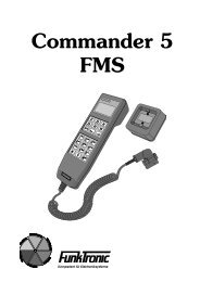
All values from 0 ... 9 and A ... F<br />
can be used for coding.<br />
B<br />
C<br />
D<br />
1 2 3<br />
4 5 6<br />
7 8 9<br />
A 0 #<br />
E<br />
F
EEPROM Addresses<br />
Register Coding for<br />
000 short call number 0<br />
. .<br />
. .<br />
. .<br />
009 short call number 9<br />
010 pre-coding of 5-tone encoder<br />
011 5-tone sequence transmitted after activating analogue input<br />
012 5-tone sequence transmitted after activating carrier input<br />
015 personally ID-code<br />
016 key tones<br />
017 standard acknowledgement<br />
020 decoder 1<br />
. .<br />
. .<br />
. .<br />
029 decoder 10<br />
030 setup for decoder 1<br />
1. position ID-Mode<br />
0 = 5-tone sequence, saved in ID-code memory<br />
1 = double sequence, call number followed by ID-code<br />
2 = double sequence, ID-code followed by call number<br />
3 = 6-tone sequence<br />
4 = 7-tone sequence<br />
5 = 8-tone sequence<br />
6 = monitor, any tone sequence is displayed<br />
7 = 5-tone sequence, not saved in ID-code memory<br />
2. position bell tone<br />
0 = no bell tone<br />
1 = bell tone 1<br />
.<br />
.<br />
9 = bell tone 9<br />
A = bell tone A<br />
3. position emergency output activated for n sec.<br />
4. position acknowledgement<br />
0 = no acknowledgement<br />
1 = standard acknowledgement<br />
2 = tone 600 Hz for 300 ms<br />
3 = personally ID code<br />
4 = received ID code<br />
5 = FFSK standard acknowledgement followed by<br />
5-tone standard acknowledgement<br />
5. position loudspeaker after decoding<br />
0 = allways of<br />
1 = activated after decoding<br />
031 setup for decoder 2<br />
. .<br />
. .<br />
. .<br />
039 setup for decoder 10<br />
040 setup for 5-tone sequence decoder<br />
- 16 -<br />
Kompetent für Elektroniksysteme
Kompetent für Elektroniksysteme<br />
1. position max. duration 1. tone, n * 5 msec * 100<br />
2. position max. duration 1. tone, n * 5 msec * 10<br />
3. position max. duration 1. tone, n * 5 msec * 1<br />
4. position min. duration all tones, n * 5 msec * 10<br />
5. position min. duration all tones, n * 5 msec * 1<br />
041 setup for 5-tone sequence decoder<br />
1. position max. duration from 2. to last tone, n * 5 msec * 100<br />
2. position max. duration from 2. to last tone, n * 5 msec * 10<br />
3. position max. duration from 2. to last tone, n * 5 msec * 1<br />
4. position<br />
5. position tone types of encoder and decoder<br />
0 = ZVEI 1<br />
1 = CCIR<br />
2 = ZVEI 2<br />
3 = EEA<br />
4 = ZVEI 3<br />
042 setup for 5-tone sequence encoder<br />
1. position duration 1. tone, n * 10 msec * 10<br />
2. position duration 1. tone, n * 10 msec * 1<br />
3. position duration from 2. to last tone, n * 10 msec<br />
4. position<br />
5. position<br />
043 setup for ID code memory<br />
1. position update on/off<br />
2. position FIFO on/off<br />
3. position display counter on/off<br />
4. position display ID code immediately on/off<br />
5. position<br />
044 setup for conference call decoder<br />
1. position tone for conference call, F = off<br />
2. position bell tone<br />
0 = no bell tone<br />
1 = bell tone 1<br />
.<br />
.<br />
9 = bell tone 9<br />
A = bell tone A<br />
3. position emergency output activated for n sec.<br />
4. position n/a<br />
5. position loudspeaker after decoding<br />
0 = allways of<br />
1 = activated after decoding<br />
045 setup for 5-tone sequence decoder, emergency call<br />
1. position max. duration 6. tone, n * 5 msec * 100<br />
2. position max. duration 6. tone, n * 5 msec * 10<br />
3. position max. duration 6. tone, n * 5 msec * 1<br />
4. position min. duration all tones, n * 5 msec * 10<br />
5. position min. duration all tones, n * 5 msec * 1<br />
046 setup for 5-tone sequence decoder, emergency call<br />
1. to 4. position key tones for emergency decoder<br />
5. position emergency tone, 6th tone<br />
- 17 -<br />
m3trc_eng (08.01.02)
047 setup for 5-tone sequence decoder, emergency call<br />
1. position n/a<br />
2. position n/a<br />
3. position time in sec. for emergency output<br />
050 loudspeaker timeout<br />
1. position n * sec * 100<br />
2. position n * sec * 10<br />
3. position n * sec * 1<br />
4. position loudspeaker allways active on/off<br />
051 1. position transmitter timeout, n * sec * 100<br />
2. position transmitter timeout, n * sec * 10<br />
3. position transmitter timeout, n * sec * 1<br />
4. position blocking after timeout, n * sec * 10<br />
5. position blocking after timeout, n * sec * 1<br />
052 transmitter keying<br />
1. position transmitter pre running time, n * 10 msec * 10<br />
2. position transmitter pre running time, n * 10 msec * 1<br />
3. position AC remote control<br />
0 = no AC remote control<br />
1 = AC remote control with 3300 Hz<br />
2 = AC remote control with 3000 Hz<br />
3 = AC remote control with Motorola <strong>TRC</strong>, 2100 Hz<br />
4. position level of pilot tone for remote control<br />
0 = 0 dBm<br />
1 = -10 dBm<br />
2 = 50 msec 0 dBm, then -10 dBm<br />
5. position PTT blocking<br />
0 = off<br />
1 = PTT blocked if carrier is detected<br />
053 setup for encoder<br />
1. position carrier display and carrier input<br />
0 = carrier input < 2V = LED on<br />
1 = carrier input > 3V = LED on<br />
2 = audio squelch<br />
3= audio squelch + transmitting tone sequence from register<br />
012 if carrier input<br />
2. position ID-Mode<br />
0 = 5-tone sequence without ID code<br />
1 = double sequence, call + ID code<br />
2 = double sequence, ID code + call<br />
3 = 6-tone sequence, call + ID code<br />
4 = 7-tone sequence, call + ID code<br />
5 = 8-tone sequence, call + ID code<br />
3. position transmitting ID code when pushing PTT<br />
0 = no ID code transmitting<br />
1 = ID code transmitted as FFSK code<br />
2 = ID code transmitted as 5-tone sequence<br />
4. position transmitting ID code when releasing PTT<br />
0 = no ID code transmitting<br />
1 = roger peep<br />
2 = ID code + status<br />
3 = ID code + status + roger peep<br />
- 18 -<br />
Kompetent für Elektroniksysteme
Kompetent für Elektroniksysteme<br />
5. position time slot between double sequence, n * 20 msec<br />
054 setup other functions<br />
1. position setup status<br />
0 = no status<br />
1 = status one digit<br />
2 = status two digit<br />
2. position n/a<br />
3. position analogue input<br />
0 = no action<br />
1 = transmitting 5-tone sequence from register 011 if input low<br />
060 FFSK setup<br />
1. position limit number hundreds<br />
2. position limit number tens<br />
3. position limit number ones<br />
4. position call system if number >= limit number<br />
5. position<br />
0 = tone sequence<br />
1 = FFSK code<br />
rhomb<br />
066 setup channel switching<br />
1. position<br />
0 = off<br />
1 = on<br />
099 Password<br />
222 load factory default values<br />
- 19 -<br />
m3trc_eng (08.01.02)
Service mode analog switches<br />
During service work it can be necessary to switch a certain signal path. Since the processor controls<br />
all analog switches they can be switched by the service program.<br />
After selecting the service mode analog switches put in the number of the switch to control. Now the<br />
input is flashing and waiting for a 0 or a 1 (0=off, 1=on).<br />
With the # key you can enter the next switch. If you enter # key again, the service mode is<br />
escaped.<br />
Service mode potentiometer<br />
During service work it can be necessary to adjust a certain signal path. Since the processor controls<br />
all potentiometers they can be adjusted by the service program.<br />
If you use a password, you have to enter when the display shows .<br />
Enter the potentiometer number to adjust. Now put in a 0 to adjust anticlockwise or a 1 for clockwise.<br />
Steps from 0 to F are possible.<br />
For adjusting TX output level (CS3) a 1000 Hz tone is transmitted automatically.<br />
Potentiometer Function Poti number<br />
CS1 loudspeaker volume 1<br />
CS2 RX input level 2<br />
CS3 TX output level 3<br />
Transmit leveling tones<br />
For leveling the <strong>Major</strong> 3 it is possible to transmit different tones. Enter setup mode number 4. The<br />
display shows now . Push a key according to the table below.<br />
To change the frequency push an other key. To escape the mode push # key.<br />
Adjustment<br />
0 = 200 Hz 5 = 1000 Hz * = 2900 Hz<br />
1 = 300 Hz 6 = 1600 Hz = 3000 Hz<br />
2 = 400 Hz 7 = 2400 Hz = 3100 Hz<br />
3 = 600 Hz 8 = 3400 Hz Z = 3300 Hz<br />
4 = 800 Hz 9 = 4000 Hz = 1200 Hz<br />
1) Adjusting audio input<br />
- Connect a signal of 1000 Hz at nominal level to the input<br />
- Disconnect the loudspeaker, connect a 8 Ohm resistor instead and level meter<br />
- Adjust the volume to max. level (9)<br />
- Switch on the loudspeaker by pushing key<br />
- Adjust the level with poti no. 2 (CS2), nominal level is + 10 dBm<br />
- 20 -<br />
Kompetent für Elektroniksysteme
Kompetent für Elektroniksysteme<br />
- 21 -<br />
m3trc_eng (08.01.02)<br />
2) Adjusting audio output<br />
- connect a level meter and the radio (line) to the audio output, the nominal level of the<br />
level tones should be - 6 dBm for 2-wire connection; for multi wire connection adjust to<br />
reach the nominal deviation of the radio<br />
- use poti no. 3 (CS3) for adjustment, 1000 Hz level tone is transmitted automatically<br />
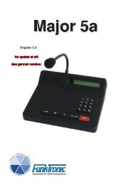
GND 14<br />
switch pin 2 15<br />
emergency output, open collector, 100 mA to GND 16<br />
audio input + 17<br />
reference voltage for digital output 19<br />
Connector male, view from rear <strong>Major</strong> 3 <strong>TRC</strong><br />
audio output + 18<br />
digital output Q1 20<br />
digital output Q3 21<br />
n.c. 22<br />
GND RS232 23<br />
+ 12 Volt 24<br />
digital GND 25<br />
1 GND<br />
2 switch pin 1<br />
3 PTT, open collector, max. 100 mA to GND<br />
4 audio input -<br />
5 audio output -<br />
6 digital output Q0<br />
7 digital output Q2<br />
8 digital output Q4<br />
9 TXD RS232<br />
10 RXD RS232<br />
11 + 12 Volt<br />
12 analog input<br />
13 carrier input<br />
- switch on pin 2 and 15 only in version without power supply, otherwise n.c.<br />
- use pin 5 and 18 for 2-Wire connection<br />
- RS232 (pin 9, 10, 23) only with option FFSK/RS232
Technical Data <strong>Major</strong> 3 <strong>Major</strong> 3 <strong>TRC</strong><br />
Supply<br />
230V version 230V AC +/- 10% 230V AC +/- 10%<br />
or or<br />
+12 V DC -10% +20% +12 V DC -10% +20%<br />
12V version +12 V DC -10% +20% +12 V DC -10% +20%<br />
Current with max. volume max. 600 mA from +12 V DC max. 600 mA from +12 V DC<br />
Input Level (RX-In)<br />
Factory default levelling - 6 dBm - 6 dBm<br />
Range of adjustment - 28 dBm to +14 dBm - 28 dBm to +14 dBm<br />
Input impedance 600 Ohm 600 Ohm<br />
Output level (TX-Out)<br />
Microphone audio default - 8 dBm - 8 dBm<br />
Microphone audio adjustment range - 21 dBm to - 7 dBm - 22 dBm to - 8 dBm<br />
Signalling audio default - 8 dBm - 6 dBm<br />
Signalling audio adjustment range - 21 dBm to - 7 dBm - 20 dBm to - 6 dBm<br />
Output impedance 600 Ohm 600 Ohm<br />
Weight<br />
220V version 1700 g 1700 g<br />
12V version 1200 g 1200 g<br />
Dimensions<br />
B x T x H 245 x 220 x 95 mm 245 x 220 x 95 mm<br />
- 22 -<br />
Kompetent für Elektroniksysteme
Change notices<br />
Change from 29.01.02 (Zier) / (Date of last version: 08.01.02):<br />
- page 4, picture M3 rear new<br />
Kompetent für Elektroniksysteme<br />
- 23 -<br />
m3trc_eng (08.01.02)