Fire-fighting Units
Fire-fighting Units
Fire-fighting Units

Create successful ePaper yourself
Turn your PDF publications into a flip-book with our unique Google optimized e-Paper software.
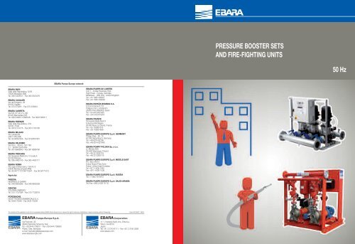
PRESSURE BOOSTER SETS<br />
AND FIRE-FIGHTING UNITS<br />
50 Hz<br />
EBARA Pumps Europe network<br />
EBARA BARI<br />
Viale della Repubblica, 52/B<br />
70026 Modugno (BA)<br />
Tel. 080 5320531 - Fax 080 5320478<br />
EBARA CAGLIARI<br />
Via del Fangario, 29<br />
09122 Cagliari<br />
Tel. 070 274281 - Fax 070 253643<br />
EBARA CASERTA<br />
Via S.S. 87 km 21+100<br />
81025 Marcianise (CE)<br />
Tel. 0823 696511/696346 - Fax 0823 696411<br />
EBARA FIRENZE<br />
Viale della Repubblica, 279<br />
59100 Prato<br />
Tel. 0574 514175 - Fax 0574 700126<br />
EBARA MILANO<br />
Via Lainate,62<br />
20017 Rho (MI)<br />
Tel. 02 93507358 - Fax 02 93507361<br />
EBARA PALERMO<br />
Via Don L. Sturzo, 181/183<br />
Z.I. - 90044 Carini (PA)<br />
Tel. 091 8680840 - Fax 091 8669790<br />
EBARA PESCARA<br />
Via Giuseppe Misticoni, 13 scala A<br />
65129 Pescara<br />
Tel. 085 4465145 - Fax 085 4465171<br />
EBARA ROMA<br />
Via Lago di Bracciano, 138 Int. 6<br />
00040 Montecompatri (RM)<br />
Tel. 06 94771127/94770541 - Fax 06 94771012<br />
Agencies<br />
PADOVA<br />
NEGRISOLO GIANNI<br />
Tel. 049 9900296 - Fax 049 9903539<br />
GENOVA<br />
VOLPARA FABRIZIO<br />
Tel. 010 7727084 - Fax 010 7729018<br />
PORDENONE<br />
GIUST TECNOCOMMERCIALE S.r.l.<br />
Tel. 0434 70040 - Fax 0434 70239<br />
EBARA PUMPS UK LIMITED<br />
Unit 7 - Zodiac Business Park<br />
High Road - Cowley Uxbridge<br />
Middlesex - UB8 2GU, United Kingdom<br />
Tel. +44 1895 439027<br />
Fax +44 1895 439028<br />
EBARA ESPAÑA BOMBAS S.A.<br />
C/Cormoranes 6 Y 8<br />
Poligono Ind. La Estación<br />
28320 Pinto (Madrid), Spain<br />
Tel. +34 916.953.630<br />
Fax +34 916.910.818<br />
EBARA FRANCE<br />
Immeuble Maille Nord II<br />
8 Avenue Montaigne<br />
93160 Noisy Le Grand, France<br />
Tel. +33 155851616<br />
Fax +33 155851639<br />
EBARA PUMPS EUROPE S.p.A. GERMANY<br />
Philipp-Reis - Str. 15<br />
63128 Dietzenbach, Germany<br />
Tel. +49 6074 82790<br />
Fax +49 6074 827942<br />
EBARA POMPY POLSKA Sp. z o.o.<br />
ul. Minska 63A<br />
03-828 Warszawa, Poland<br />
Tel. +48 22 3308118<br />
Fax +48 22 3308119<br />
EBARA PUMPS EUROPE S.p.A. MIDDLE EAST<br />
P.O. Box 54515<br />
Dubai Airport Free Zone<br />
Dubai, United Arab Emirates<br />
Tel. +971 4 609 1040<br />
Fax +971 4 609 1038<br />
EBARA PUMPS EUROPE S.p.A. RUSSIA<br />
Tel. +7 985 7672672<br />
EBARA PUMPS EUROPE S.p.A. SAUDI ARABIA<br />
Tel./Fax +966 2 629 76 78<br />
The contents of this publication must not be considered binding. EBARA Pumps Europe S.p.A. reserves the right to make any modifications it deems necessary without forewarning. Code 479705422 09/09<br />
EBARA Pumps Europe S.p.A.<br />
Via Pacinotti, 32<br />
36040 Brendola (Vicenza), Italy<br />
Tel. +39 0444 706811 - Fax +39 0444 706950<br />
Plants: Cles, Brendola<br />
e-mail: marketing@ebaraeurope.com<br />
www.ebaraeurope.com<br />
EBARA Corporation<br />
11-1, Haneda Asahi-cho, Ohta-ku,<br />
Tokyo 144-8510<br />
Japan<br />
Tel. +81 3 3743 6111 - Fax +81 3 3745 3356<br />
www.ebara.com
INDEX<br />
PRESSURE BOOSTING<br />
DOMESTIC PRESSURE BOOSTING at fixed speed (GP)<br />
Introduction 2<br />
2GP AGA 6<br />
2GP CDA 9<br />
2GP 2CDX 12<br />
2GP COMPACT 15<br />
2GP MATRIX 18<br />
2GP CVM 22<br />
2GP HVM 26<br />
3GP CVM 29<br />
3GP HVM 33<br />
DOMESTIC PRESSURE BOOSTING at variable speed (GPE)<br />
2GPE COMPACT 36<br />
2GPE MATRIX 39<br />
2GPE CVM 43<br />
2GPE HVM 47<br />
INDUSTRIAL PRESSURE BOOSTING at fixed speed (GP)<br />
2GP 3M 50<br />
2GP EVMG 57<br />
3GP 3M 69<br />
3GP EVMG 76<br />
INDUSTRIAL PRESSURE BOOSTING at variable speed (GPE)<br />
2GPE 3M 88<br />
2GPE EVMG 95<br />
3GPE 3M 107<br />
3GPE EVMG 114<br />
Electric control panels 126<br />
FIRE-FIGHTING<br />
PUMPS BASE-JOINT (3PS - ENRS)<br />
General considerations regarding the UNI EN 12845 Standard 130<br />
<strong>Fire</strong>-<strong>fighting</strong> introduction 132<br />
FFS-FFBE electric pump 140<br />
FFBD motor pump 151<br />
FFBD electric pump + motor pump 156<br />
VERTICAL MULTISTAGE PUMPS (EVMG)<br />
FFS electric pump 159<br />
SUBMERSED PUMPS (SF6 - WINNER 4N15 - BHE)<br />
FFS-S hydraulic elements kit 168<br />
Electric control panels 177<br />
Technical appendix 184<br />
Your Life, our Quality. Worldwide. 1 Booster & <strong>Fire</strong>-Fighting
GP - GPE<br />
PRESSURE BOOSTER UNITS<br />
use of the same.<br />
N.B. By connecting a float or minimum pressure pressure switch to<br />
the control panel (whether for withdrawal from the primary<br />
collection reservoir or from the hydraulic circuit), the most frequent<br />
cause of electric pump breakdown is prevented: the lack of water at<br />
suction.<br />
DEFINITION AND USE<br />
OF THE PRESSURE BOOSTER UNITS<br />
If the public water distribution system is inexistent or insufficient for<br />
correct functioning of the utilities, it is necessary to install a<br />
pressure boosting unit in order to guarantee an acceptable pressure<br />
and amount of water also in the most unfavourable points of use.<br />
The pressure boosting unit is applied every time the pressure must<br />
be increases or where the mains water must be pressurised.<br />
The GPs, EBARA pressure boosting units, are small automatic<br />
systems with 2 or more pumps in parallel, studied and realised<br />
simply and reliably to satisfy the most recurrent pressure<br />
maintenance requests in the water supply of condominiums, hotels,<br />
centres, offices, schools, auxiliary services in the industrial and<br />
agricultural ambit. They are distinguished for the construction<br />
strength, compactness, high efficiency and silence.<br />
The GP units are set-up for the membrane autoclaves or air pocket<br />
connection.<br />
Start-up of the individual pumps is caused by the activation of<br />
pressure switches, appropriately calibrated via an electric control<br />
panel. In the units controlled with electric control panel with<br />
INVERTER, as well as pressure switches, one of the pumps is started<br />
via the calibration of a pressure transducer.<br />
FUNCTIONING PRINCIPLE<br />
OF THE PRESSURE BOOSTER UNIT GP<br />
If water is requested, this is initially withdrawn from the autoclave<br />
reservoir, whenever the system is provided.<br />
This consumption of water or, however, the escape of water from<br />
the system, with pumps off, determines the lowering of the<br />
pressure to a value such to trip the closure of the pressure switch<br />
contact with higher calibration, which determines the ignition of<br />
the first electric pump.<br />
If the outlet discharge exceeds the flow rate of a pump, the<br />
pressure continues to drop until it causes the closure of the contact<br />
of the second pressure switch and the start-up of the second pump.<br />
This takes place for all of the electric pumps that make up the unit.<br />
The end of the distribution of the reduction of the outlet discharge<br />
leads to the pressure in the system rising, with opening of the<br />
pressure switch contacts and staggered pumps stops. The inversion<br />
of the ignition order of the motors reduces the number of hourly<br />
start-ups of the individual pumps and consequently a homogenous<br />
FUNCTIONING PRINCIPLE<br />
OF THE PRESSURE BOOSTING UNIT GPE<br />
The GPE unit is designed to function with a pump governed by a<br />
frequency converter “INVERTER” inserted into the electric control<br />
panel and the others with direct intervention.<br />
This unit, thus constructed, allows to maintain constant pressure in<br />
the water network.<br />
On variation of the network pressure, the INVERTER governed pump<br />
varies its own rotation speed, stating the pressure of the set value.<br />
Whenever the water withdrawal should exceed the pump flow rate,<br />
the second pump intervenes directly and, in the meantime, that<br />
governed by the INVERTER goes into regulation mode in order to<br />
keep the water pressure at the set value. This takes place for all of<br />
the pumps making up the unit.<br />
When the withdrawal has been closed, the pump governed by the<br />
INVERTER reaches the minimum rotation value and, after a few<br />
minutes, stops allowing to obtain a large energy saving.<br />
It is possible to have various versions of the GPE units:<br />
• With an individual INVERTER, which governs just one pump, but<br />
different from the previous start-up (Standard EFC Version).<br />
• With multi-inverter, where every pump is controlled by an inverter<br />
(MFC versions and HERTZ TWIN versions).<br />
Contolling a unit via SP EFC control panels<br />
The SP EFC for controlling units with several pumps envision<br />
powering the pump n°1 via inverter in order to modulate<br />
performance of the system depending on the reference signal,<br />
while the other electric pumps are made to work at maximum<br />
nominal speed (about 2900 min-1) with insertion and<br />
disconnection in sequence on variation of the request.<br />
This implies the presence of two distinct primary electric<br />
circuits:<br />
1st- pump start-up via inverter, 2nd- start-up (direct of deltatriangle)<br />
of the other pumps, by contactors.<br />
The system is governed by the “SYSTEM CONTROLLER” control<br />
unit on the basis of the reference signal, which derives from a<br />
pressure transmitter, flow rate measuring device or other<br />
unified control signal (4÷20 mA passive).<br />
• In the case of water distribution with constant start pressure<br />
(Fig.1), the control unit is connected to the pressure<br />
transmitter positioned in the discharge manifold of the unit<br />
that will send a proportional signal to the network pressure.<br />
The lowering of the network pressure, following water<br />
withdrawal, causes a reduction of the pressure transmitter<br />
signal, which, via the control unit, will control start-up, via<br />
inverter, of the first pump regulating its speed in a way to reestablish<br />
the reference/work pressure. If the flow rate of the<br />
pump is lower than that requested, the network pressure will<br />
tend to decrease and the system will react by increasing the<br />
pump rotation speed. Once the maximum speed of pump n°1<br />
Your Life, our Quality. Worldwide. 2 Booster & <strong>Fire</strong>-Fighting
GP - GPE<br />
PRESSURE BOOSTER UNITS<br />
has been reached, if the pump flow rate is still lower than that<br />
requested, the control unit will control the start-up of the<br />
second pump, which will work at constant speed.<br />
Pump n°1 will be immediately positioned in the conditions to<br />
modulate the rotation speed in order to take the pressure back<br />
to the work value. If the network pressure should drop even<br />
further, once the maximum rotation speed on pump n°1 has<br />
been reached again, the control unit will control start-up of<br />
pump n°3 and successively of any pump n°4. When there is a<br />
reduction of water withdrawal, the pressure tends to increase<br />
as does the pressure signal transmitter. The control unit will<br />
reduce the rotation speed of the pump n°1 in order to reestablish<br />
the reference/work pressure. If the pump flow rate<br />
exceeds that requested, the network pressure will tend to<br />
increase and the system will react by decreasing the pump<br />
rotation speed until the minimum value set is reached. At this<br />
point, the control unit will control stopping of pump n°4,<br />
while pump n°1 will be put in the conditions to modulate the<br />
rotation speed in order to take the pressure back to the work<br />
value On further decrease of the request for flow rate with<br />
consequent tendency on increase in network pressure, once<br />
the minimum rotation speed has been reached again on pump<br />
n°1, the control unit will stop pump n°3 and successively<br />
pump n°2. When the demand for water ceases, the control<br />
unit will reduce the rotation speed of pump n°1 to the<br />
minimum value and after the re-set time (about 1 minute) it<br />
will also stop this pump.<br />
• The case of functioning with increasing set pressure is shown<br />
in an example, for a unit with two pumps, in Fig. 2. While the<br />
system controls just one pump the reference pressure is SET1.<br />
The transmitter pressure signal is compared with SET1, a<br />
lowering or increase in active pressure, through the control<br />
unit, pump rotation speed modulation. Once the maximum<br />
speed of pump n°1 has been reached, if the pressure is below<br />
the work value, the control unit will control start-up of pump<br />
n°2 and the reference pressure becomes SET2.<br />
The reference pressure will remain SET2 while the control unit<br />
keeps pumps n°1 and n°2 running. It will go back to the SET1<br />
value when the control unit controls shutdown of pump n°2.<br />
Contolling a unit via TWIN and SP MFC control panels<br />
The SP MFC and TWIN control panels for controlling units with<br />
several pumps, envision powering each pump via an inverter in<br />
order to modulate system performance depending on the reference<br />
signal. From a construction point of view, the two types of control<br />
panel are different while from a functional point of view ruling is<br />
similar and always takes place by the SYSTEM CONTROLLER control<br />
unit. This acts on the basis of the reference signal, which is derived<br />
from a pressure transmitter, flow rate measuring device or other<br />
unified control signal (4÷20 mA passive).On these control panels,<br />
every pump is powered by the respective inverter and whenever a<br />
fault occurs on the control unit or pressure transducer, if connected,<br />
a system of pressure switches sub-enters, which controls the inviters<br />
directly.<br />
Fig. 1 - UNIT WITH TWO PUMPS WITH CONSTANT PRESSURE REGULATION<br />
Reference<br />
pressure<br />
Head H[m]<br />
1 Pump 2 Pumps<br />
Flow rate Q [%]<br />
Fig. 2 - UNIT WITH TWO PUMPS WITH REGULATION SET AT TWO LEVELS<br />
System<br />
curve<br />
Head H[m]<br />
1 Pump 2 Pumps<br />
Flow rate Q [%]<br />
Your Life, our Quality. Worldwide. 3 Booster & <strong>Fire</strong>-Fighting
GP - GPE<br />
PRESSURE BOOSTER UNITS<br />
• In the case of water distribution with constant start pressure<br />
(Fig.1), the control unit is connected to the pressure transmitter<br />
positioned in the discharge manifold of the unit that will send a<br />
proportional signal to the network pressure. The lowering of the<br />
network pressure following water withdrawal causes a reduction of<br />
the pressure transmitter signal, which, via the control unit, will<br />
control start-up, via inverter, of the first pump regulating its speed<br />
in a way to re-establish the reference/work pressure.<br />
If the flow rate of the pump is lower than that requested, the<br />
network pressure will tend to decrease and the system will react by<br />
increasing the pump rotation speed. Once the maximum speed of<br />
pump n°1 has been reached, if the pump flow rate is still lower<br />
than the request, the control unit will control start-up of the second<br />
pump, which will also work with various speeds. The two pumps<br />
will be immediately placed in conditions to modulate the rotation<br />
speed in order to take the pressure to the work value. The<br />
modulation frequency is the same for both pumps, therefore, as<br />
noted in Fig.1, when both pumps operate, the curves are different<br />
with respect to that highlighted in Fig.1. If the network pressure<br />
should lower further, once the maximum rotation speed on pump<br />
n°1 is reached again, the control unit will control the start-up of<br />
pump n°3 and successively also pump n°4. When there is a<br />
reduction of the withdrawal of water the pressure tends to increase<br />
as does the pressure transmitter signal. The control unit will reduce<br />
the rotation speed of pumps n°1, n°2, n°3 and n°4 (the four pumps<br />
are modulated in parallel) in order to re-establish the<br />
reference/work pressure. If the pump flow rate exceeds that<br />
requested, the network pressure will tend to increase and the<br />
system will react by decreasing the rotation speed of the pumps<br />
until the minimum value set for pump n° 4. At this point, the<br />
control unit will control stopping of pump n°4 while pumps n°1,<br />
n°2 and n°3 will be put in the conditions to modulate the speed of<br />
rotation in order to take the pressure back to the work value. On<br />
further decrease of the flow rate request, with consequent<br />
tendency of increase of the network pressure, once the minimum<br />
rotation speed set for pump n°3 has been reached, the control unit<br />
will control the stopping of pump n°3 while the rotation speed on<br />
pumps n°1 and n°2 will be modulated. On successive decrease of<br />
the request, the control unit will also stop pump n°2 and will<br />
modulate the speed of pump n°1. When the demand for water<br />
stops, the control unit will reduce the rotation speed of pump n°1<br />
to the minimum value and after the pre-set time (about 1 minute)<br />
will also stop this pump.<br />
• Also for these types of control panels there is functioning with<br />
incremental pressure set in order to compensate the pressure drops<br />
(pressure transmitter positioned at start). The control unit operates<br />
in steps with two pressure steps; when just pump n°1 is started, the<br />
reference set is SET1 and becomes SET2 when both pumps are<br />
started, as represented in Fig.2. Both pumps are modulated in<br />
parallel.<br />
CONDITIONS FOR USE<br />
The GP-GPE EBARA pressure boosting units, can be used, in the<br />
standard versions, for civil, industrial and agricultural applications,<br />
in particular for:<br />
• lifting or moving water<br />
• air conditioning<br />
• heating<br />
• irrigation<br />
• washing systems<br />
The liquid conveyed can be: clean water, drinkable, rain, sheet,<br />
mixed or however without solid bodies or fibres in suspension and<br />
without aggressive chemical substances.<br />
The units must be installed in environments that are covered and<br />
protected from weather conditions and freezing.<br />
• Temperature of the conveyed water is 0°÷50°C (according to the<br />
types of pumps installed).<br />
• Environmental functioning area is 0°÷40°C at a height not<br />
exceeding 1000 m a.s.l.<br />
• Max. relative humidity 50% at +40°C.<br />
N.B. The available system NPSH must be greater than the NPSH<br />
requested by the pump.<br />
For applications with different technical features, uses, climatic<br />
conditions (type of liquid conveyed, marine environment, aggressive<br />
industrial environment) contact our sales network .<br />
TESTS AND INSPECTIONS<br />
All EBARA pressure boosting units undergo hydraulic, mechanical<br />
and electrical tests before packaging.<br />
HYDRAULIC MECHANICAL TESTS<br />
Pressure switch calibration Verification of the pump rotation<br />
direction<br />
• Mechanical test of moving parts and noise test (on every pump)<br />
• Sealing test at closed discharge inlet and verification of plate head<br />
• Functioning test in MANUAL (via button on electric control panel)<br />
of each individual pump<br />
• Functioning test in AUTOMATIC (via switch on electric control<br />
panel) of the unit<br />
ELECTRIC TESTS<br />
• Verification of continuity of the earth circuit<br />
• Test at applied voltage (dielectric strength).<br />
• Isolation resistance test<br />
Your Life, our Quality. Worldwide. 4 Booster & <strong>Fire</strong>-Fighting
GP - GPE<br />
PRESSURE BOOSTER UNITS<br />
PRESSURE BOOSTING UNIT HYDRAULIC LAYOUT WITH PUMPS IN PARALLEL<br />
KEY<br />
1 Electric pump<br />
2 Suction manifold<br />
3 Shut-off valve in suction<br />
4 Non-return valve<br />
5 Shut-off valve in discharge<br />
6 Discharge manifold<br />
7 Shut-off valve<br />
8 Pump control/regulation pressure switches<br />
9 Pressure gauge<br />
10 Membrane vessel (Optional*)<br />
USE<br />
UNDERHEAD<br />
OVERHEAD<br />
SUPPLY SYSTEM UPSTREAM FROM THE UNIT<br />
AT THE DISCRETION OF THE CUSTOMER<br />
OF THE SYSTEM DESIGNER<br />
PRESSURE BOOSTING UNIT LAYOUT AND COMPONENTS<br />
KEY<br />
1 Electric pump<br />
2 Suction manifold<br />
3 Ball shut-off valve<br />
4 Non-return valve<br />
5 Air vent nipple<br />
6 Ball shut-off valve<br />
7 Discharge manifold<br />
8 Ball shut-off valve<br />
9 Pump control/regulation pressure switches<br />
10 Pressure gauge<br />
11 Membrane vessel (Optional*)<br />
12 Control panel<br />
13 Pressure transducer (on request)<br />
14 Bracket/sleeve set-up<br />
manifold anchorage<br />
*<br />
Your Life, our Quality. Worldwide. 5 Booster & <strong>Fire</strong>-Fighting
2GP AGA<br />
DOMESTIC PRESSURE BOOSTING<br />
TYPICAL APPLICATIONS<br />
The base of the group is in galvanised steel as are the manifolds. The<br />
discharge manifold is set-up to gather two vertical membrane<br />
reservoirs. Mounted on them find two pressure switches, the electric<br />
control panel and a pressure gauge. On suction, each electric pump has<br />
an isolating valve and a non-return valve, with the possibility of<br />
connection to an air supply unit and has another isolating valve in<br />
discharge mode.<br />
<strong>Units</strong> with two horizontal self-priming single impeller pumps with cast<br />
iron hydraulic parts.<br />
PUMP FEATURES<br />
FIELD OF USE<br />
• Maximum working pressure:<br />
6 bar (AGA 1.00)<br />
10 bar for the rest of the range<br />
• Maximum temperature of the liquid: 45°C<br />
• Maximum suction depth: 8 m<br />
MATERIALS<br />
• Cast iron pump body<br />
• Seal housing disc AISI 304<br />
• Shaft in AISI 416<br />
• Impeller and nozzle in PPO reinforced with fibreglass<br />
• Mechanical seal in Carbon/Ceramic/NBR<br />
TECHNICAL DATA<br />
• Self-ventilated 2 pole asynchronous motor<br />
• Class of insulation F<br />
• IP44 Protection rating<br />
• 230V ± 10% 50Hz single phase voltage<br />
230/400V ± 10% 50Hz three phase voltage<br />
• Permanent capacitor inserted and thermo-amperometric protection<br />
with automatic reset incorporated for the single phase motor<br />
• Protection under user's responsibility for the three phase version<br />
Protection and control panel with CE mark<br />
• IMQ and VDE marked components<br />
• Very low voltage auxiliary circuit<br />
• Motor switch-on and switch-off are controlled by two pressure<br />
switches<br />
• The connection to a float of minimum pressure pressure switch is<br />
possible in order to prevent functioning in conditions when there is no<br />
suction water<br />
• A device is present that inverts the insertion order of the pumps at<br />
every start-up<br />
• Power supply:<br />
- 230V, 50Hz single phase<br />
- 400V, 50 Hz three phase<br />
• Direct start-up<br />
• Power circuit protection fuse<br />
• Auxiliary circuit protection fuse<br />
• Protection rating IP 55<br />
• Line general isolating switch with door lock<br />
• Aut. - 0 - man. switches for each pump<br />
• Circuit breaker protection reset<br />
• LED indicator: - network presence<br />
- motor running<br />
- level alarm<br />
- motor in protection mode (for three phase version only)<br />
• Alarm output set-up<br />
• On request, special version control panels can be used<br />
FUNCTIONING PRINCIPLES<br />
The withdrawal or however the escape of water from the system with<br />
the pumps at a standstill, causes the pressure to drop and the<br />
consequent closure of the pressure switch contact with highest<br />
calibration, which determines start-up of the first electric pump. If the<br />
outlet discharge exceeds the flow rate of a pump, the pressure<br />
continues to drop until it causes the closure of the contact of the<br />
second pressure switch and the start-up of the second pump. The end<br />
of the distribution of the reduction of the outlet discharge leads to the<br />
pressure in the system rising, with opening of the pressure switch<br />
contacts and staggered pumps stops. The inversion of the ignition order<br />
of the two motors reduces the number of hourly start-ups of the<br />
individual pumps and consequently allows a homogenous use of the<br />
same. By connecting a float or minimum pressure pressure switch to the<br />
control panel (whether for withdrawal from the primary collection<br />
reservoir or from the hydraulic circuit), the most frequent cause of<br />
electric pump breakdown is prevented: the lack of water at suction.<br />
Your Life, our Quality. Worldwide. 6 Booster & <strong>Fire</strong>-Fighting
2GP AGA<br />
DOMESTIC PRESSURE BOOSTING<br />
2GP AGA 1.00 range PERFORMANCE CURVES<br />
(according to ISO 9906 Attachment A)<br />
2GP AGA 1.50 - 2.00 - 3.00 range PERFORMANCE CURVES<br />
(according to ISO 9906 Attachment A)<br />
PERFORMANCE TABLE AND ELECTRIC DATA OF THE TWO PUMPS FUNCTIONING SIMULTANEOUSLY<br />
Model Max absorption Q=Flow rate<br />
230V 400V [A] l/min 10 20 40 60 90 100 120 160 200<br />
single phase three-phase [kW] 230V 400V m 3 /h 0,6 1,2 2,4 3,6 5,4 6 7,2 9,6 12<br />
single phase three-phase<br />
H=Head [m]<br />
AGA 1.00 M AGA 1.00 T 0.75+0.75 11 4,2 47,5 45 40,3 35,7 29,1 27 23 - -<br />
AGA 1.50 M AGA 1.50 T 1.1+1.1 16,2 6 - 48 45,1 42,4 38,6 37,4 35,1 30,8 27<br />
AGA 2.00 M AGA 2.00 T 1.5+1.5 19,6 7,2 - 59 55,6 52,2 47,3 45,7 42,5 36,4 30,5<br />
- AGA 3.00 T 2.2+2.2 - 9,4 - 68 64,3 60,8 55,9 54,4 51,6 46,4 42<br />
Your Life, our Quality. Worldwide. 7 Booster & <strong>Fire</strong>-Fighting
2GP AGA<br />
DOMESTIC PRESSURE BOOSTING<br />
DIMENSIONS<br />
DIMENSIONS TABLE<br />
Model Dimensions [mm] Weight<br />
A B B1 C D M R Q HQ DNA DNM [kg]<br />
[2] [1] [2] [1]<br />
2GP AGA 1.00 (M) 485 210 275 415 770 770 370 1090 - - 560 G2 G1½ 51,0<br />
2GP AGA 1.50 (M) 525 230 295 495 870 870 470 1130 - - 600 G2½ G1½ 78,0<br />
2GP AGA 2.00 (M) 525 230 295 495 885 870 470 1130 15 - 600 G2½ G1½ 78,0<br />
2GP AGA 3.00 525 230 295 495 - 885 470 1130 - 15 600 G2½ G1½ 80,0<br />
[1]= Three-phase only<br />
[2]= Single phase only<br />
Your Life, our Quality. Worldwide. 8 Booster & <strong>Fire</strong>-Fighting
2GP CDA<br />
DOMESTIC PRESSURE BOOSTING<br />
TYPICAL APPLICATIONS<br />
The base of the group is in galvanised steel as are the manifolds. The<br />
discharge manifold is set-up to gather any two vertical type membrane<br />
reservoirs; two pressure switches, the electric control panel and a<br />
pressure gauge are mounted on it.<br />
On inlet, each electric pump has an isolating valve and a non-return<br />
valve, with the possibility of connection to an air supply unit and has<br />
another isolating valve in discharge mode.<br />
<strong>Units</strong> with two horizontal dual impeller pumps with cast iron hydraulic<br />
parts.<br />
PUMP FEATURES<br />
FIELD OF USE<br />
• Maximum working pressure:<br />
- 6 bar for CDA 0.75 - 1.00<br />
- 10 bar for the rest of the range<br />
• Maximum temperature of the liquid:<br />
- 40°C for CDA 0.75 - 1.00<br />
- 90°C for the rest of the range<br />
MATERIALS<br />
• Cast iron pump body<br />
• Mechanical seal in Carbon/Ceramic/NBR<br />
• Impeller: - in technopolymer for CDA 0.75 - 1.00<br />
- in brass for the rest of the range<br />
• Shaft: - in AISI 303 for CDA 1.50 - 2.00 - 3.00<br />
- in AISI 304 for CDA 4.00 - 5.50<br />
- in AISI 416 for the rest of the range<br />
• Support: - in aluminium for CDA 0.75 - 1.00<br />
- in cast iron for the rest of the range<br />
• Seal housing disc: - in AISI 304 for CDA 0.75 - 1.00<br />
- in cast iron for the rest of the range<br />
TECHNICAL DATA<br />
• Self-ventilated 2 pole asynchronous motor<br />
• Class of insulation F<br />
• Protection rating IP44<br />
• 230V ± 10% 50Hz, single phase voltage<br />
230/400V ± 10% 50Hz three phase voltage<br />
• Permanent capacitor inserted and<br />
thermo-amperometric protection with automatic reset incorporated<br />
for the single phase motor<br />
• Protection under user's responsibility for the three phase version<br />
Protection and control panel with CE mark<br />
• IMQ and VDE marked components<br />
• Very low voltage auxiliary circuit<br />
• Motor switch-on and switch-off are controlled by two pressure<br />
switches<br />
• The connection to a float of minimum pressure pressure switch is<br />
possible in order to prevent functioning in conditions when there is no<br />
suction water<br />
• A device is present that inverts the insertion order of the pumps at<br />
every start-up<br />
• Power supply:<br />
- 230V, 50Hz single phase<br />
- 400V, 50 Hz three phase<br />
• Direct start-up<br />
• Power circuit protection fuses<br />
• Auxiliary circuit protection fuses<br />
• Protection rating IP 55<br />
• Line main isolating device with door lock<br />
• Aut - 0 - man. switches for each pump<br />
• Reset circuit breaker protection<br />
• Indicator LED:<br />
- network presence<br />
- motor running<br />
- level alarm<br />
- motor in protection mode (for three phase version only)<br />
• Alarm output set-up<br />
• On request, special version control panels can be used<br />
FUNCTIONING PRINCIPLES<br />
The withdrawal or however the escape of water from the system with<br />
the pumps at a standstill, causes the pressure to drop and the<br />
consequent closure of the pressure switch contact with highest<br />
calibration, which determines start-up of the first electric pump. If the<br />
outlet discharge exceeds the flow rate of a pump, the pressure<br />
continues to drop until it causes the closure of the contact of the<br />
second pressure switch and the start-up of the second pump. The end<br />
of the distribution of the reduction of the outlet discharge leads to the<br />
pressure in the system rising, with opening of the pressure switch<br />
contacts and staggered pumps stops. The inversion of the ignition order<br />
of the two motors reduces the number of hourly start-ups of the<br />
individual pumps and consequently allows a homogenous use of the<br />
same. By connecting a float or minimum pressure pressure switch to the<br />
control panel (whether for withdrawal from the primary collection<br />
reservoir or from the hydraulic circuit), the most frequent cause of<br />
electric pump breakdown is prevented: the lack of water at suction.<br />
Your Life, our Quality. Worldwide. 9 Booster & <strong>Fire</strong>-Fighting
2GP CDA<br />
DOMESTIC PRESSURE BOOSTING<br />
2GP CDA range PERFORMANCE CURVES<br />
(according to ISO 9906 Attachment A)<br />
PERFORMANCE TABLE AND ELECTRIC DATA OF THE TWO PUMPS FUNCTIONING SIMULTANEOUSLY<br />
Model Max absorption Q=Flow rate<br />
230V 230/400V [A] l/min 40 80 100 160 180 200 220 240 280 380 420<br />
single phase three-phase [kW] 230V 230/400V m 3 /h 2,4 4,8 8 9,6 10,8 12 13,2 14,4 16,8 22,8 25,2<br />
single phase three-phase<br />
H=Head [m]<br />
CDA 1,00M CDA 1,00T 0,75 + 0,75 12,2 4,6 39,5 37,0 35,2 27,0 21,0 - - - - - -<br />
CDA 1,50M CDA 1,50T 1,1 + 1,1 18 6,8 50,8 49,0 47,0 38,4 33,4 27,5 - - - - -<br />
CDA 2,00M CDA 2,00T 1,5 + 1,5 21,6 8,6 60,5 58,5 57,0 50,0 46,5 40,5 32,5 - - - -<br />
- CDA 3,00T 2,2 + 2,2 - 10,2 - 60,5 59,5 54,0 51,5 48,5 44,5 40,5 32,0 - -<br />
- CDA 4,00T 3 + 3 - 15 - - 67,0 65,0 64,0 62,5 62,0 61,0 58,0 48,0 -<br />
- CDA 5,50T 4 + 4 - 19 - - 76,5 74,0 73,0 72,0 70,5 69,0 67,0 58,5 54,0<br />
Your Life, our Quality. Worldwide. 10 Booster & <strong>Fire</strong>-Fighting
2GP CDA<br />
DOMESTIC PRESSURE BOOSTING<br />
DIMENSIONS<br />
DIMENSIONS TABLE<br />
Model Dimensions [mm] Weight<br />
A B B1 C C1 D DNA DNM HQ M Q R [kg]<br />
2GP CDA 100 530 160 370 425 395 730 G2 G1½ 600 350 - 1135 66,0<br />
2GP CDA 150 565 170 395 420 385 730 G2 G1½ 640 340 10 1170 90,0<br />
2GP CDA 200 585 170 415 420 385 745 G2 G2 650 340 25 1185 94,0<br />
2GP CDA 300 625 170 455 490 445 815 G2½ G2½ 705 405 30 1245 98,0<br />
2GP CDA 400 635 195 440 475 430 845 G2½ G2½ 715 390 75 1255 130,0<br />
2GP CDA 550 635 195 440 475 430 845 G2½ G2½ 715 390 75 1255 138,0<br />
Your Life, our Quality. Worldwide. 11 Booster & <strong>Fire</strong>-Fighting
2GP 2CDX<br />
DOMESTIC PRESSURE BOOSTING<br />
TYPICAL APPLICATIONS<br />
The base of the group is in galvanised steel as are the manifolds. The<br />
discharge manifold is set-up to gather two vertical membrane<br />
reservoirs. Mounted on them find two pressure switches, the electric<br />
control panel and a pressure gauge. On suction, each electric pump has<br />
an isolating valve and a non-return valve, with the possibility of<br />
connection to an air supply unit and has another isolating valve in<br />
discharge mode.<br />
<strong>Units</strong> with two horizontal dual impeller pumps with stainless steel<br />
hydraulic parts.<br />
PUMP FEATURES<br />
FIELD OF USE<br />
• Maximum working pressure: 8 bar<br />
• Maximum temperature of the liquid: 60°C<br />
MATERIALS<br />
• Pump body, impeller, shaft, nozzle and seal housing disc<br />
in AISI 304<br />
• Motor support in aluminium (up to 1.5 kW included), in cast iron<br />
(2.2 kW and over).<br />
TECHNICAL DATA<br />
• Self-ventilated 2 pole asynchronous motor<br />
• Class of insulation F<br />
• Protection rating IP55<br />
• 230V ± 10% 50Hz, single phase voltage<br />
230/400V ±10% 50Hz three phase voltage<br />
• Permanent capacitor inserted and<br />
thermo-amperometric protection with automatic reset incorporated<br />
for the single phase motor<br />
Protection and control panel with CE mark<br />
• IMQ and VDE marked components<br />
• Very low voltage auxiliary circuit<br />
• Motor switch-on and switch-off are controlled by two pressure<br />
switches<br />
• The connection to a float of minimum pressure pressure switch is<br />
possible in order to prevent functioning in conditions when there is no<br />
suction water<br />
• A device is present that inverts the insertion order of the pumps at<br />
every start-up<br />
• Power supply: - 230V, 50Hz single phase<br />
- 400V, 50 Hz three phase<br />
• Direct start-up<br />
• Power circuit protection fuses<br />
• Auxiliary circuit protection fuses<br />
• Protection rating IP 55<br />
• Line main isolating device with door lock<br />
• Aut - 0 - man. switches for each pump<br />
• Reset circuit breaker protection<br />
• Indicator LED:<br />
- network presence<br />
- motor running<br />
- level alarm<br />
- motor in protection mode (for three phase version only)<br />
• Alarm output set-up<br />
• On request, special version control panels can be used<br />
FUNCTIONING PRINCIPLES<br />
The withdrawal or however the escape of water from the system with<br />
the pumps at a standstill, causes the pressure to drop and the<br />
consequent closure of the pressure switch contact with highest<br />
calibration, which determines start-up of the first electric pump. If the<br />
outlet discharge exceeds the flow rate of a pump, the pressure<br />
continues to drop until it causes the closure of the contact of the<br />
second pressure switch and the start-up of the second pump. The end<br />
of the distribution of the reduction of the outlet discharge leads to the<br />
pressure in the system rising, with opening of the pressure switch<br />
contacts and staggered pumps stops. The inversion of the ignition order<br />
of the two motors reduces the number of hourly start-ups of the<br />
individual pumps and consequently allows a homogenous use of the<br />
same. By connecting a float or minimum pressure pressure switch to the<br />
control panel (whether for withdrawal from the primary collection<br />
reservoir or from the hydraulic circuit), the most frequent cause of<br />
electric pump breakdown is prevented: the lack of water at suction.<br />
Your Life, our Quality. Worldwide. 12 Booster & <strong>Fire</strong>-Fighting
2GP 2CDX<br />
DOMESTIC PRESSURE BOOSTING<br />
2GP 2CDX 70 range PERFORMANCE CURVES<br />
(according to ISO 9906 Attachment A)<br />
2GP 2CDX 120 range PERFORMANCE CURVES<br />
(according to ISO 9906 Attachment A)<br />
2GP 2CDX 200 range PERFORMANCE CURVES<br />
(according to ISO 9906 Attachment A)<br />
Your Life, our Quality. Worldwide. 13 Booster & <strong>Fire</strong>-Fighting
2GP 2CDX<br />
DOMESTIC PRESSURE BOOSTING<br />
PERFORMANCE TABLE AND ELECTRIC DATA OF THE TWO PUMPS FUNCTIONING SIMULTANEOUSLY<br />
Model Max absorption Q=Flow rate<br />
230V 400V [A] l/min 40 80 120 160 200 240 300 360 420<br />
single phase three-phase [kW] 230V 400V m 3 /h 2,4 4,8 7,2 9,6 12 14,4 18 21,6 25,2<br />
single phase three-phase<br />
H=Head [m]<br />
2CDXM 70/10 2CDX 70/10 0,75 + 0,75 12 4,6 38,5 35,0 31,5 27,0 - - - - -<br />
2CDXM 70/12 2CDX 70/12 0,9 + 0,9 14 5,8 44,5 40,3 35,2 29,0 - - - - -<br />
2CDXM 70/15 2CDX 70/15 1,1 + 1,1 16,2 6,6 52,5 48,0 42,8 36,5 - - - - -<br />
2CDXM 70/20 2CDX 70/20 1,5 + 1,5 20 8 60,0 55,6 50,0 44,0 - - - - -<br />
2CDXM 120/15 2CDX 120/15 1,1 + 1,1 16,6 6,6 - 42,0 41,5 39,5 37,5 35,0 30,0 - -<br />
2CDXM 120/20 2CDX 120/20 1,5 + 1,5 20,4 8 - 51,5 49,5 47,0 45 42,0 36,5 - -<br />
- 2CDX 120/30 2,2 + 2,2 - 10 - 59,0 57,0 54,6 52 49,0 44,0 - -<br />
- 2CDX 120/40 3 + 3 - 12,4 - 68,5 66,5 64,0 61 57,5 52,0 - -<br />
- 2CDX 200/30 2,2 + 2,2 - 12 - - 52,0 51,0 49,5 48,0 45,5 42,6 39,5<br />
- 2CDX 200/40 3 + 3 - 13,2 - - 62,5 61,0 59,5 58,0 55,0 52,2 49,0<br />
- 2CDX 200/50 3,7 + 3,7 - 17,4 - - 71,5 70,0 68,5 67,0 64,0 61,3 57,5<br />
DIMENSIONS<br />
DIMENSIONS TABLE<br />
Model Dimensions [mm] Weight<br />
A B B1 C C1 D DNA DNM HQ M R [kg]<br />
2GP 2CDX 70/10 525 165 360 420 385 800 G2 G1½ 625 400 1130 53,0<br />
2GP 2CDX 70/12 525 165 360 420 385 800 G2 G1½ 625 400 1130 54,0<br />
2GP 2CDX 70/15 550 180 370 420 385 800 G2 G1½ 650 400 1155 60,0<br />
2GP 2CDX 70/20 550 180 370 420 385 800 G2 G1½ 650 400 1155 64,0<br />
2GP 2CDX 120/15 535 165 370 485 445 880 G2½ G2 635 465 1145 60,0<br />
2GP 2CDX 120/20 535 165 370 485 445 880 G2½ G2 635 465 1145 63,0<br />
2GP 2CDX 120/30 555 180 375 485 445 880 G2½ G2 685 480 1165 76,0<br />
2GP 2CDX 120/40 555 180 375 485 445 880 G2½ G2 685 480 1165 83,0<br />
2GP 2CDX 200/30 585 165 420 465 425 860 G2½ G2½ 690 460 1205 80,0<br />
2GP 2CDX 200/40 610 180 430 465 425 860 G2½ G2½ 715 460 1230 80,0<br />
2GP 2CDX 200/50 610 180 430 465 425 860 G2½ G2½ 715 460 1230 95,0<br />
Your Life, our Quality. Worldwide. 14 Booster & <strong>Fire</strong>-Fighting
2GP COMPACT<br />
DOMESTIC PRESSURE BOOSTING<br />
TYPICAL APPLICATIONS<br />
The base of the group is in galvanised steel as are the manifolds. The<br />
discharge manifold is set-up to gather any two vertical type membrane<br />
reservoirs. Two pressure switches, the electric control panel and a<br />
pressure gauge are mounted on it. On suction, each electric pump has<br />
an isolating valve and a non-return valve, with the possibility of<br />
connection to an air supply unit and has another isolating valve in<br />
discharge mode.<br />
<strong>Units</strong> with two horizontal multistage pumps.<br />
PUMP FEATURES<br />
FIELD OF USE<br />
• Maximum working pressure: 10 bar<br />
• Maximum temperature of the liquid: 40°C<br />
MATERIALS<br />
• Cast iron pump body and support<br />
• External casing in AISI 304<br />
• Technopolymer impeller and nozzle<br />
• Shaft in AISI 416<br />
TECHNICAL DATA<br />
• Self-ventilated 2 pole asynchronous motor<br />
• Class of insulation F<br />
• IP44 Protection rating<br />
• 230V ±10%, 50Hz single phase voltage,<br />
230/400V ±10%, 50Hz three phase voltage<br />
• Permanent capacitor inserted and thermo-amperometric protection<br />
with automatic reset incorporated for the single phase motor<br />
• Protection under user's responsibility for the three phase version<br />
Protection and control panel with CE mark<br />
• IMQ and VDE marked components<br />
• Very low voltage auxiliary circuit<br />
• Motor switch-on and switch-off are controlled by two pressure<br />
switches<br />
• The connection to a float of minimum pressure pressure switch is<br />
possible in order to prevent functioning in conditions when there is no<br />
suction water<br />
• A device is present that inverts the insertion order of the pumps at<br />
every start-up<br />
• Power supply:<br />
- 230V, 50Hz single phase<br />
- 400V, 50 Hz three phase<br />
• Direct start-up<br />
• Power circuit protection fuse<br />
• Auxiliary circuit protection fuse<br />
• Protection rating IP 55<br />
• Line general isolating switch with door lock<br />
• Aut. - 0 - man. switches for each pump<br />
• Circuit breaker protection reset<br />
• LED indicator:<br />
- network presence<br />
- motor running<br />
- level alarm<br />
- motor in protection mode (for three phase version only)<br />
• Alarm output set-up<br />
• On request, special version control panels can be used<br />
FUNCTIONING PRINCIPLES<br />
The withdrawal or however the escape of water from the system with<br />
the pumps at a standstill, causes the pressure to drop and the<br />
consequent closure of the pressure switch contact with highest<br />
calibration, which determines start-up of the first electric pump. If the<br />
outlet discharge exceeds the flow rate of a pump, the pressure<br />
continues to drop until it causes the closure of the contact of the<br />
second pressure switch and the start-up of the second pump. The end<br />
of the distribution of the reduction of the outlet discharge leads to the<br />
pressure in the system rising, with opening of the pressure switch<br />
contacts and staggered pumps stops. The inversion of the ignition order<br />
of the two motors reduces the number of hourly start-ups of the<br />
individual pumps and consequently allows a homogenous use of the<br />
same. By connecting a float or minimum pressure pressure switch to the<br />
control panel (whether for withdrawal from the primary collection<br />
reservoir or from the hydraulic circuit), the most frequent cause of<br />
electric pump breakdown is prevented: the lack of water at suction.<br />
Your Life, our Quality. Worldwide. 15 Booster & <strong>Fire</strong>-Fighting
2GP COMPACT<br />
DOMESTIC PRESSURE BOOSTING<br />
2GP COMPACT A range PERFORMANCE CURVES<br />
(according to ISO 9906 Attachment A)<br />
2GP COMPACT B range PERFORMANCE CURVES<br />
(according to ISO 9906 Attachment A)<br />
PERFORMANCE TABLE AND ELECTRIC DATA OF THE TWO PUMPS FUNCTIONING SIMULTANEOUSLY<br />
Model Max absorption Q=Flow rate<br />
230V 400V [A] l/min 40 80 120 160 200 240<br />
single phase three-phase [kW] 230V 400V m 3 /h 2,4 4,8 7,2 9,6 12 14,4<br />
single phase three-phase H=Head [m]<br />
COMPACT AM 8 COMPACT A 8 0,60 + 0,6 8 3 39,7 32,0 22,4 10,5 - -<br />
COMPACT AM 10 COMPACT A 10 0,75 + 0,75 12 4,8 56,5 48,6 37,1 20,0 - -<br />
COMPACT AM 12 COMPACT A 12 0,88 + 0,88 12,4 5,4 67,5 58,4 44,9 24,0 - -<br />
COMPACT AM 15 COMPACT A 15 1,1 + 1,1 14,6 6,6 79,0 69,1 54,0 28,0 - -<br />
COMPACT BM 12 COMPACT B 12 0,88 + 0,88 11,6 5,4 - 45,9 41,3 35,2 27,6 18,0<br />
COMPACT BM 15 COMPACT B 15 1,1 + 1,1 14,6 6,8 - 56,0 51,5 44,5 34,5 22,0<br />
Your Life, our Quality. Worldwide. 16 Booster & <strong>Fire</strong>-Fighting
2GP COMPACT<br />
DOMESTIC PRESSURE BOOSTING<br />
DIMENSIONS<br />
DIMENSIONS TABLE<br />
Model Dimensions [mm] Weight<br />
B B1 C C1 D DNA M Q [kg]<br />
2GP COMPACT A(M)8 190 285 525 490 815 G2 270 65 52,0<br />
2GP COMPACT A(M)10 185 290 555 520 840 G2 295 105 61,0<br />
2GP COMPACT A(M)12 185 290 580 545 865 G2 320 105 63,0<br />
2GP COMPACT A(M)15 185 290 605 570 890 G2 345 120 65,0<br />
2GP COMPACT B(M)12 185 290 575 530 860 G2½ 315 105 64,0<br />
2GP COMPACT B(M)15 185 290 600 560 890 G2½ 345 120 66,0<br />
Your Life, our Quality. Worldwide. 17 Booster & <strong>Fire</strong>-Fighting
2GP MATRIX<br />
DOMESTIC PRESSURE BOOSTING<br />
TYPICAL APPLICATIONS<br />
The base of the group is in galvanised steel as are the manifolds. The<br />
discharge manifold is set-up to gather any two vertical type membrane<br />
reservoirs; two pressure switches, the electric control panel and a<br />
pressure gauge are mounted on it. On inlet, each electric pump has an<br />
isolating valve and a non-return valve, with the possibility of connection<br />
to an air supply unit and has another isolating valve in discharge mode.<br />
<strong>Units</strong> with two horizontal multistage pumps with stainless steel<br />
hydraulic parts.<br />
PUMP FEATURES<br />
FIELD OF USE<br />
• Maximum temperature of the liquid: 110°C<br />
• Maximum working pressure: 10 bar<br />
• Maximum chlorine content: 500 ppm<br />
MATERIALS<br />
• Pump body, impeller, intermediate body, and seal housing disc and<br />
shaft in AISI 304<br />
• Mechanical sealing in Carbon/Ceramic/EPDM<br />
• Support and motor casing in aluminium<br />
TECHNICAL DATA<br />
• Self-ventilated 2 pole asynchronous motor<br />
• Class of insulation F<br />
• IP55 Protection rating<br />
• 230V ±10%, 50Hz single phase voltage,<br />
230/400V ±10%, 50Hz three phase voltage<br />
• Permanent capacitor inserted and thermo-amperometric protection<br />
with automatic reset incorporated for the single phase motor<br />
Protection and control panel with CE mark<br />
• IMQ and VDE marked components<br />
• Very low voltage auxiliary circuit<br />
• Motor switch-on and switch-off are controlled by two pressure<br />
switches<br />
• The connection to a float of minimum pressure pressure switch is<br />
possible in order to prevent functioning in conditions when there is no<br />
suction water<br />
• A device is present that inverts the insertion order of the pumps at<br />
every start-up<br />
• Power supply: 230V, 50Hz single phase<br />
400V, 50 Hz three phase<br />
• Direct start-up<br />
• Power circuit protection fuses<br />
• Auxiliary circuit protection fuses<br />
• Protection rating IP 55<br />
• Line main isolating device with door lock<br />
• Aut - 0 - man. switches for each pump<br />
• Reset circuit breaker protection<br />
• Indicator LED:<br />
- network presence<br />
- motor running<br />
- level alarm<br />
- motor in protection mode (for three phase version only)<br />
• Alarm output set-up<br />
• On request, special version control panels can be used<br />
FUNCTIONING PRINCIPLES<br />
The withdrawal or however the escape of water from the system with<br />
the pumps at a standstill, causes the pressure to drop and the<br />
consequent closure of the pressure switch contact with highest<br />
calibration, which determines start-up of the first electric pump. If the<br />
outlet discharge exceeds the flow rate of a pump, the pressure<br />
continues to drop until it causes the closure of the contact of the<br />
second pressure switch and the start-up of the second pump. The end<br />
of the distribution of the reduction of the outlet discharge leads to the<br />
pressure in the system rising, with opening of the pressure switch<br />
contacts and staggered pumps stops. The inversion of the ignition order<br />
of the two motors reduces the number of hourly start-ups of the<br />
individual pumps and consequently allows a homogenous use of the<br />
same. By connecting a float or minimum pressure pressure switch to the<br />
control panel (whether for withdrawal from the primary collection<br />
reservoir or from the hydraulic circuit), the most frequent cause of<br />
electric pump breakdown is prevented: the lack of water at suction.<br />
Your Life, our Quality. Worldwide. 18 Booster & <strong>Fire</strong>-Fighting
2GP MATRIX<br />
DOMESTIC PRESSURE BOOSTING<br />
2GP MATRIX 3 range PERFORMANCE CURVES<br />
(according to ISO 9906 Attachment A)<br />
2GP MATRIX 5 range PERFORMANCE CURVES<br />
(according to ISO 9906 Attachment A)<br />
2GP MATRIX 10 range PERFORMANCE CURVES<br />
(according to ISO 9906 Attachment A)<br />
2GP MATRIX 18 range PERFORMANCE CURVES<br />
(according to ISO 9906 Attachment A)<br />
Your Life, our Quality. Worldwide. 19 Booster & <strong>Fire</strong>-Fighting
2GP MATRIX<br />
DOMESTIC PRESSURE BOOSTING<br />
PERFORMANCE TABLE AND ELECTRIC DATA OF THE TWO PUMPS FUNCTIONING SIMULTANEOUSLY<br />
Model Max absorption Q=Flow rate<br />
230V 400V [A] l/min 40 60 120 160 200 260 320 400 500 600 700 800 900<br />
single phase three-phase [kW] 230V 400V m 3 /h 2,4 3,6 7,2 9,6 12 15,6 19,2 24 30 36 42 48 54<br />
single phase three-phase<br />
H=Head [m]<br />
MATRIX 3-4/0.65M MATRIX 3-4/0.65 0,65+0,65 9 3,2 42,0 39,1 27,2 16,0 - - - - - - - - -<br />
MATRIX 3-5/0.75M MATRIX 3-5/0.75 0,75+0,75 10,8 5 52,5 49,0 34,0 20,0 - - - - - - - - -<br />
MATRIX 3-6/0.9M MATRIX 3-6/0.9 0,9+0,9 11,4 5,2 62,5 58,5 41,0 24,0 - - - - - - - - -<br />
MATRIX 3-7/1.3M MATRIX 3-7/1.3 1,3+1,3 15,6 7 73,0 68,5 47,5 28,0 - - - - - - - - -<br />
MATRIX 3-8/1.3M MATRIX 3-8/1.3 1,3+1,3 15,6 7 83,5 78,0 54,5 32,0 - - - - - - - - -<br />
MATRIX 3-9/1.5M MATRIX 3-9/1.5 1,5+1,5 17,4 6,8 94,0 88,0 61,0 36,0 - - - - - - - - -<br />
MATRIX 5-4/0.9M MATRIX 5-4/0.9 0,9+0,9 11,4 5,2 - 43,0 38,6 34,7 29,4 17,6 - - - - - - -<br />
MATRIX 5-5/1.3M MATRIX 5-5/1.3 1,3+1,3 15,6 7 - 54,0 48,5 43,5 36,7 22,0 - - - - - - -<br />
MATRIX 5-6/1.3M MATRIX 5-6/1.3 1,3+1,3 15,6 7 - 64,5 58,0 52,0 44,0 26,4 - - - - - - -<br />
MATRIX 5-7/1.5M MATRIX 5-7/1.5 1,5+1,5 17,4 6,8 - 75,5 67,5 61,0 51,5 30,8 - - - - - - -<br />
MATRIX 5-8/2.2M MATRIX 5-8/2.2 2,2+2,2 26 9,2 - 86,0 77,0 69,5 58,5 35,2 - - - - - - -<br />
MATRIX 5-9/2.2M MATRIX 5-9/2.2 2,2+2,2 26 9,2 - 97,0 87,0 78,0 66,0 39,6 - - - - - - -<br />
MATRIX 10-3/1.3M MATRIX 10-3/1.3 1,3+1,3 15,6 7 - - 33,3 32,1 30,9 28,6 25,5 19,3 8,7 - - - -<br />
MATRIX 10-4/1.5M MATRIX 10-4/1.5 1,5+1,5 17,4 6,8 - - 44,5 43,0 41,0 38,1 34,0 25,7 11,6 - - - -<br />
MATRIX 10-5/2.2M MATRIX 10-5/2.2 2,2+2,2 26 9,2 - - 55,5 53,5 51,5 47,5 42,5 32,1 14,5 - - - -<br />
MATRIX 10-6/2.2M MATRIX 10-6/2.2 2,2+2,2 26 9,2 - - 66,5 64,5 62,0 57,0 51,0 38,5 17,4 - - - -<br />
MATRIX 18-3/2.2M MATRIX 18-3/2.2 2,2+2,2 26 9,2 - - - - - 33,0 31,9 30,4 28,1 25,2 21,3 15,5 7,8<br />
- MATRIX 18-4/3.0 3+3 - 12,6 - - - - - 44,0 42,5 40,5 37,4 33,6 28,4 20,6 10,4<br />
- MATRIX 18-5/4.0 4+4 - 16,2 - - - - - 55,0 53,0 50,5 47,0 42,0 35,5 25,8 13,0<br />
- MATRIX 18-6/4.0 4+4 - 16,2 - - - - - 66,0 64,0 60,5 56,0 50,5 42,5 30,9 15,6<br />
DIMENSIONS<br />
Your Life, our Quality. Worldwide. 20 Booster & <strong>Fire</strong>-Fighting
2GP MATRIX<br />
DOMESTIC PRESSURE BOOSTING<br />
DIMENSIONS TABLE<br />
Model Dimensions [mm] Weight<br />
A B C C1 D DNA DNM HQ L R S [kg]<br />
[2] [1] [2] [1]<br />
2GP MATRIX 3-4M/0,65 2GP MATRIX 3-4T/0,65 490 340 255 450 740 50 40 550 565 520 1100 380 54,0 54,0<br />
2GP MATRIX 3-5M/0,75 2GP MATRIX 3-5T/0,75 490 340 255 475 765 50 40 550 565 520 1100 380 58,0 58,0<br />
2GP MATRIX 3-6M/0,9 2GP MATRIX 3-6T/0,9 490 340 255 500 790 50 40 550 565 520 1100 380 61,0 61,0<br />
2GP MATRIX 3-7M/1,3 2GP MATRIX 3-7T/1,3 490 340 295 520 850 50 40 550 565 520 1100 550 68,0 68,0<br />
2GP MATRIX 3-8M/1,3 2GP MATRIX 3-8T/1,3 490 340 295 545 875 50 40 550 565 520 1100 550 68,0 69,0<br />
2GP MATRIX 3-9M/1,5 2GP MATRIX 3-9T/1,5 490 340 295 570 900 50 40 550 565 520 1100 550 72,0 71,0<br />
2GP MATRIX 5-4M/0,9 2GP MATRIX 5-4T/0,9 500 350 295 490 825 65 50 560 575 520 1110 380 62,0 62,0<br />
2GP MATRIX 5-5M/1,3 2GP MATRIX 5-5T/1,3 500 350 295 515 850 65 50 560 575 520 1110 380 67,0 66,0<br />
2GP MATRIX 5-6M/1,3 2GP MATRIX 5-6T/1,3 500 350 295 535 875 65 50 560 575 520 1110 380 70,0 69,0<br />
2GP MATRIX 5-7M/1,5 2GP MATRIX 5-7T/1,5 500 350 295 560 895 65 50 560 575 520 1110 550 75,0 74,0<br />
2GP MATRIX 5-8M/2,2 2GP MATRIX 5-8T/2,2 500 350 305 585 935 65 50 575 575 520 1110 550 86,0 78,0<br />
2GP MATRIX 5-9M/2,2 2GP MATRIX 5-9T/2,2 500 350 305 610 960 65 50 575 575 520 1110 550 86,0 78,0<br />
2GP MATRIX 10-3M/1,3 2GP MATRIX 10-3T/1,3 515 365 300 510 855 80 65 585 600 520 1135 380 72,0 70,0<br />
2GP MATRIX 10-4M/1,5 2GP MATRIX 10-4T/1,5 515 365 300 540 885 80 65 585 600 520 1135 380 73,0 73,0<br />
2GP MATRIX 10-5M/2,2 2GP MATRIX 10-5T/2,2 515 365 310 570 930 80 65 600 600 520 1135 380 85,0 78,0<br />
2GP MATRIX 10-6M/2,2 2GP MATRIX 10-6T/2,2 515 365 310 600 960 80 65 600 600 520 1135 550 89,0 81,0<br />
2GP MATRIX 18-3M/2,2 2GP MATRIX 18-3T/2,2 575 425 315 520 895 100 80 660 660 620 1200 380 94,0 87,0<br />
- 2GP MATRIX 18-4T/3,0 575 425 350 555 965 100 80 660 660 620 1200 550 - 98,0<br />
- 2GP MATRIX 18-5T/3,8 575 425 385 595 1000 100 80 660 660 620 1200 550 - 109,0<br />
- 2GP MATRIX 18-6T/4,0 575 425 385 630 1075 100 80 660 660 620 1200 550 - 111,0<br />
[1]= Three-phase<br />
[2]= Single phase<br />
Your Life, our Quality. Worldwide. 21 Booster & <strong>Fire</strong>-Fighting
2GP CVM<br />
DOMESTIC PRESSURE BOOSTING<br />
TYPICAL APPLICATIONS<br />
The base of the group is in galvanised steel as are the manifolds. The<br />
discharge manifold is set-up to gather any two vertical type membrane<br />
reservoirs. Two pressure switches, the electric control panel and a<br />
pressure gauge are mounted on it. On suction, each electric pump has<br />
an isolating valve and a non-return valve, with the possibility of<br />
connection to an air supply unit and has another isolating valve in<br />
discharge mode.<br />
<strong>Units</strong> with two vertical multistage pumps.<br />
PUMP FEATURES<br />
FIELD OF USE<br />
• Maximum working pressure: 11 bar<br />
• Maximum temperature of the liquid: 40°C<br />
MATERIALS<br />
• Cast iron pump body and motor support<br />
• External casing in AISI 304<br />
• Impeller and nozzle in PPE+PS reinforced with fibreglass<br />
• Shaft in AISI 416<br />
TECHNICAL DATA<br />
• Self-ventilated 2 pole asynchronous motor<br />
• Class of insulation F<br />
• IP44 Protection rating<br />
• 230V ±10%, 50Hz single phase voltage,<br />
230/400V ±10%, 50Hz three phase voltage<br />
• Permanent capacitor inserted and thermo-amperometric protection<br />
with automatic reset incorporated for the single phase motor<br />
Protection and control panel with CE mark<br />
• IMQ and VDE marked components<br />
• Very low voltage auxiliary circuit<br />
• Motor switch-on and switch-off are controlled by two pressure<br />
switches<br />
• The connection to a float of minimum pressure pressure switch is<br />
possible in order to prevent functioning in conditions when there is no<br />
suction water<br />
• A device is present that inverts the insertion order of the pumps at<br />
every start-up<br />
• Power supply: - 230V, 50Hz single phase<br />
- 400V, 50 Hz three phase<br />
• Direct start-up<br />
• Power circuit protection fuse<br />
• Auxiliary circuit protection fuse<br />
• Protection rating IP 55<br />
• Line general isolating switch with door lock<br />
• Aut. - 0 - man. switches for each pump<br />
• Circuit breaker protection reset<br />
• LED indicator:<br />
- network presence<br />
- motor running<br />
- level alarm<br />
- motor in protection mode (for three phase version only)<br />
• Alarm output set-up<br />
• On request, special version control panels can be used<br />
FUNCTIONING PRINCIPLES<br />
The withdrawal or however the escape of water from the system with<br />
the pumps at a standstill, causes the pressure to drop and the<br />
consequent closure of the pressure switch contact with highest<br />
calibration, which determines start-up of the first electric pump. If the<br />
outlet discharge exceeds the flow rate of a pump, the pressure<br />
continues to drop until it causes the closure of the contact of the<br />
second pressure switch and the start-up of the second pump. The end<br />
of the distribution of the reduction of the outlet discharge leads to the<br />
pressure in the system rising, with opening of the pressure switch<br />
contacts and staggered pumps stops. The inversion of the ignition order<br />
of the two motors reduces the number of hourly start-ups of the<br />
individual pumps and consequently allows a homogenous use of the<br />
same. By connecting a float or minimum pressure pressure switch to the<br />
control panel (whether for withdrawal from the primary collection<br />
reservoir or from the hydraulic circuit), the most frequent cause of<br />
electric pump breakdown is prevented: the lack of water at suction.<br />
Your Life, our Quality. Worldwide. 22 Booster & <strong>Fire</strong>-Fighting
2GP CVM<br />
DOMESTIC PRESSURE BOOSTING<br />
2GP CVM A 8 range PERFORMANCE CURVES<br />
(according to ISO 9906 Attachment A)<br />
2GP CVM A 10 - A 12 - A 15 range PERFORMANCE CURVES<br />
(according to ISO 9906 Attachment A)<br />
EFFICIENCY<br />
EFFICIENCY<br />
HEAD<br />
HEAD<br />
2GP CVM A 18 range PERFORMANCE CURVES<br />
(according to ISO 9906 Attachment A)<br />
Your Life, our Quality. Worldwide. 23 Booster & <strong>Fire</strong>-Fighting
2GP CVM<br />
DOMESTIC PRESSURE BOOSTING<br />
2GP CVM B 10 - B 12 - B 15 range PERFORMANCE CURVES<br />
(according to ISO 9906 Attachment A)<br />
2GP CVM B 20 - B 23 - B 25 range PERFORMANCE CURVES<br />
(according to ISO 9906 Attachment A)<br />
EFFICIENCY<br />
HEAD<br />
PERFORMANCE TABLE AND ELECTRIC DATA OF THE TWO PUMPS FUNCTIONING SIMULTANEOUSLY<br />
Model Max absorption Q=Flow rate<br />
230V 400V [A] l/min 40 60 80 100 120 160 200 240<br />
single phase three-phase [kW] 230V 400V m 3 /h 2,4 3,6 4,8 6 7,2 9,6 12 14,4<br />
single phase three-phase H=Head [m]<br />
CVM AM/8 CVM A/8 0,6+0,6 8 3,2 42,5 39,4 35,6 31,1 25,9 12,8 - -<br />
CVM AM/10 CVM A/10 0,75+0,75 12 4,6 57,5 54,0 49,5 43,5 36,6 19,5 - -<br />
CVM AM/12 CVM A/12 0,9+0,9 13 5,6 69,0 65,0 59,5 52,5 44,0 23,4 - -<br />
CVM AM/15 CVM A/15 1,1+1,1 14,4 6,6 80,5 75,5 69,5 61,0 51,0 27,3 - -<br />
CVM AM/18 CVM A/18 1,3+1,3 15,6 6,2 94,5 88,0 80,0 70,0 58,5 28,8 - -<br />
CVM BM/10 CVM B/10 0,75+0,75 11,2 4,8 - 36,2 35,1 33,7 32,0 27,5 21,6 14,7<br />
CVM BM/12 CVM B/12 0,9+0,9 12,4 5,4 - 48,0 46,8 45,0 42,6 36,6 28,8 19,6<br />
CVM BM/15 CVM B/15 1,1+1,1 14,8 6,4 - 60,5 58,5 56,2 53,3 45,8 36,0 24,5<br />
CVM BM/20 CVM B/20 1,5+1,5 16,6 6,6 - 74,0 72,0 69,0 65,5 56,0 44,5 30,6<br />
CVM BM/23 CVM B/23 1,7+1,7 19,2 8,6 - 86,0 84,0 80,5 76,5 65,5 51,5 35,7<br />
- CVM B/25 1,85+1,85 - 8,6 - 98,5 96,0 92,0 87,0 74,5 59,0 41,0<br />
Your Life, our Quality. Worldwide. 24 Booster & <strong>Fire</strong>-Fighting
2GP CVM<br />
DOMESTIC PRESSURE BOOSTING<br />
DIMENSIONS<br />
DIMENSIONS TABLE<br />
Model Dimensions [mm] Weight<br />
A B R DNA DNM [kg]<br />
2GP CVM A(M)8 260 165 865 G2 G2 61,0<br />
2GP CVM A(M)10 285 190 890 G2 G2 65,0<br />
2GP CVM A(M)12 310 215 915 G2 G2 66,0<br />
2GP CVM A(M)15 335 240 940 G2 G2 67,0<br />
2GP CVM A(M)18 365 270 970 G2 G2 73,0<br />
2GP CVM B(M)10 235 140 840 G2 G2 64,0<br />
2GP CVM B(M)12 260 165 865 G2 G2 65,0<br />
2GP CVM B(M)15 285 190 890 G2 G2 66,0<br />
2GP CVM B(M)20 310 215 915 G2 G2 72,0<br />
2GP CVM B(M)23 335 240 940 G2 G2 76,0<br />
2GP CVM B25 365 270 970 G2 G2 78,0<br />
Your Life, our Quality. Worldwide. 25 Booster & <strong>Fire</strong>-Fighting
2GP HVM<br />
DOMESTIC PRESSURE BOOSTING<br />
TYPICAL APPLICATIONS<br />
The base of the group is in galvanised steel as are the manifolds. The<br />
discharge manifold is set-up to gather any two vertical type membrane<br />
reservoirs. Two pressure switches, the electric control panel and a<br />
pressure gauge are mounted on it. On suction, each electric pump has<br />
an isolating valve and a non-return valve, with the possibility of<br />
connection to an air supply unit and has another isolating valve in<br />
discharge mode.<br />
<strong>Units</strong> with two vertical multistage pumps with stainless steel hydraulic<br />
parts.<br />
PUMP FEATURES<br />
FIELD OF USE<br />
• Maximum working pressure: 10 bar<br />
• Maximum temperature of the liquid: 90°C<br />
MATERIALS<br />
• Cast iron pump body<br />
• External casing, impellers, intermediate stage, seal housing disc and<br />
shaft in AISI 304<br />
• Mechanical seal in Carbon/Ceramic/NBR<br />
TECHNICAL DATA<br />
• T.E.F.C. 2 pole motor<br />
• Class of insulation F<br />
• IP55 Protection rating<br />
• 230V ±10%, 50Hz single phase voltage,<br />
230/400V ±10%, 50Hz three phase voltage<br />
• Permanent capacitor inserted and thermo-amperometric protection<br />
with automatic reset incorporated for the single phase motor<br />
• Circuit breaker protection under user's responsibility for the three<br />
phase version<br />
Protection and control panel with CE mark<br />
• IMQ and VDE marked components<br />
• Very low voltage auxiliary circuit<br />
• Motor switch-on and switch-off are controlled by two pressure<br />
switches<br />
• The connection to a float of minimum pressure pressure switch is<br />
possible in order to prevent functioning in conditions when there is no<br />
suction water<br />
• A device is present that inverts the insertion order of the pumps at<br />
every start-up<br />
• Power supply:<br />
- 230V, 50Hz single phase<br />
- 400V, 50 Hz three phase<br />
• Direct start-up<br />
• Power circuit protection fuse<br />
• Auxiliary circuit protection fuse<br />
• Protection rating IP 55<br />
• Line general isolating switch with door lock<br />
• Aut. - 0 - man. switches for each pump<br />
• Circuit breaker protection reset<br />
• LED indicator:<br />
- network presence<br />
- motor running<br />
- level alarm<br />
- motor in protection mode (for three phase version only)<br />
• Alarm output set-up<br />
• On request, special version control panels can be used<br />
FUNCTIONING PRINCIPLES<br />
The withdrawal or however the escape of water from the system with<br />
the pumps at a standstill, causes the pressure to drop and the<br />
consequent closure of the pressure switch contact with highest<br />
calibration, which determines start-up of the first electric pump. If the<br />
outlet discharge exceeds the flow rate of a pump, the pressure<br />
continues to drop until it causes the closure of the contact of the<br />
second pressure switch and the start-up of the second pump. The end<br />
of the distribution of the reduction of the outlet discharge leads to the<br />
pressure in the system rising, with opening of the pressure switch<br />
contacts and staggered pumps stops. The inversion of the ignition order<br />
of the two motors reduces the number of hourly start-ups of the<br />
individual pumps and consequently allows a homogenous use of the<br />
same. By connecting a float or minimum pressure pressure switch to the<br />
control panel (whether for withdrawal from the primary collection<br />
reservoir or from the hydraulic circuit), the most frequent cause of<br />
electric pump breakdown is prevented: the lack of water at suction.<br />
Your Life, our Quality. Worldwide. 26 Booster & <strong>Fire</strong>-Fighting
2GP HVM<br />
DOMESTIC PRESSURE BOOSTING<br />
2GP HVM 3 range PERFORMANCE CURVES<br />
(according to ISO 9906 Attachment A)<br />
2GP HVM 5 range PERFORMANCE CURVES<br />
(according to ISO 9906 Attachment A)<br />
2GP HVM A 10 range PERFORMANCE CURVES<br />
(according to ISO 9906 Attachment A)<br />
Your Life, our Quality. Worldwide. 27 Booster & <strong>Fire</strong>-Fighting
2GP HVM<br />
DOMESTIC PRESSURE BOOSTING<br />
PERFORMANCE TABLE AND ELECTRIC DATA OF THE TWO PUMPS FUNCTIONING SIMULTANEOUSLY<br />
Model Max absorption Q=Flow rate<br />
230V 400V [A] l/min 40 60 90 120 160 200 260 320 400 500<br />
single phase three-phase [kW] 230V 400V m 3 /h 2,4 3,6 5,4 7,2 9,6 12 15,6 19,2 24 30<br />
single phase three-phase<br />
H=Head [m]<br />
HVM 3-5N/0.9M HVM 3-5N/0.9 0,9+0,9 11,4 5,2 52,5 49,0 42,5 34,0 20,0 - - - - -<br />
HVM 3-6N/0.9M HVM 3-6N/0.9 0,9+0,9 11,4 5,2 62,5 58,5 51,0 41,0 24,0 - - - - -<br />
HVM 3-7N/1.5M HVM 3-7N/1.5 1,5+1,5 17,4 6,8 73,0 68,5 59,5 47,5 28,0 - - - - -<br />
HVM 3-8N/1.5M HVM 3-8N/1.5 1,5+1,5 17,4 6,8 83,5 78,0 68,0 54,5 32,0 - - - - -<br />
HVM 3-9N/1.5M HVM 3-9N/1.5 1,5+1,5 17,4 6,8 94,0 88,0 76,5 61,0 36,0 - - - - -<br />
HVM 5-6N/1.5M HVM 5-6N/1.5 1,5+1,5 17,4 6,8 - 64,5 61,5 58,0 52,0 44,0 26,4 - - -<br />
HVM 5-7N/1.5M HVM 5-7N/1.5 1,5+1,5 17,4 6,8 - 75,5 71,5 67,5 61,0 51,5 30,8 - - -<br />
HVM 5-8N/2.2M HVM 5-8N/2.2 2,2+2,2 26 9,2 - 86,0 82,0 77,0 69,5 58,5 35,2 - - -<br />
HVM 5-9N/2.2M HVM 5-9N/2.2 2,2+2,2 26 9,2 - 97,0 92,0 87,0 78,0 66,0 39,6 - - -<br />
HVM 10-4N/1.5M HVM 10-4N/1.5 1,5+1,5 17,4 6,8 - - - 44,5 43,0 41,0 38,1 34,0 25,7 11,6<br />
HVM 10-5N/2.2M HVM 10-5N/2.2 2,2+2,2 26 9,2 - - - 55,5 53,5 51,5 47,5 42,5 32,1 14,5<br />
HVM 10-6N/2.2M HVM 10-6N/2.2 2,2+2,2 26 9,2 - - - 66,5 64,5 62,0 57,0 51,0 38,5 17,4<br />
- HVM 10-7N/3 3+3 - 12,6 - - - 77,5 75,0 72,0 66,5 59,5 45,0 20,3<br />
- HVM 10-8N/3 3+3 - 12,6 - - - 89,0 85,5 82,5 76,0 68,0 51,5 23,2<br />
DIMENSIONS<br />
DIMENSIONS TABLE<br />
Model Dimensions [mm] Weight [kg]<br />
L H H1 H2 P P1 L1 DNA-DNM<br />
[2] [1] [2] [1] [2] [1] [2] [1]<br />
2GP HVM 3-5N/0.9 805 835 110 570 570 740 800 860 695 660 G2 82,0 84,0<br />
2GP HVM 3-6N/0.9 805 835 110 595 595 740 800 860 695 660 G2 84,0 86,0<br />
2GP HVM 3-7N/1.5 805 835 110 655 655 740 800 860 695 660 G2 90,0 92,0<br />
2GP HVM 3-8N/1.5 805 835 110 680 680 740 800 860 695 660 G2 90,0 93,0<br />
2GP HVM 3-9N/1.5 805 835 110 705 705 740 800 860 695 660 G2 94,0 95,0<br />
2GP HVM 5-6N/1.5 775 805 110 635 635 740 800 800 635 660 G2 88,0 91,0<br />
2GP HVM 5-7N/1.5 775 805 110 655 655 740 800 800 635 660 G2 92,0 93,0<br />
2GP HVM 5-8N/2.2 775 805 110 730 695 740 800 800 635 660 G2 103,0 97,0<br />
2GP HVM 5-9N/2.2 775 805 110 750 720 740 800 800 635 660 G2 104,0 97,0<br />
2GP HVM 10-4N/1.5 815 845 140 640 640 740 800 920 740 670 G3 97,0 99,0<br />
2GP HVM 10-5N/2.2 845 845 140 715 680 800 800 920 740 670 G3 109,0 104,0<br />
2GP HVM 10-6N/2.2 845 845 140 745 710 800 800 920 740 670 G3 112,0 105,0<br />
2GP HVM 10-7N/3 - 845 140 - 775 - 800 920 740 670 G3 - 113,0<br />
2GP HVM 10-8N/3 - 845 140 - 805 - 800 920 740 670 G3 - 115,0<br />
[1]= Three-phase only<br />
[2]= Single phase only<br />
Your Life, our Quality. Worldwide. 28 Booster & <strong>Fire</strong>-Fighting
3GP CVM<br />
DOMESTIC PRESSURE BOOSTING<br />
TYPICAL APPLICATIONS<br />
The base of the group is in galvanised steel as are the manifolds. The<br />
discharge manifold is set-up to gather any three vertical type membrane<br />
reservoirs. Three pressure switches, the electric control panel and a<br />
pressure gauge are mounted on it. On suction, each electric pump has<br />
an isolating valve and a non-return valve, with the possibility of<br />
connection to an air supply unit and has another isolating valve in<br />
discharge mode.<br />
<strong>Units</strong> with three vertical multistage pumps.<br />
PUMP FEATURES<br />
FIELD OF USE<br />
• Maximum working pressure: 11 bar<br />
• Maximum temperature of the liquid: 40°C<br />
MATERIALS<br />
• Cast iron pump body and motor support<br />
• External casing in AISI 304<br />
• Impeller and nozzle in PPE+PS reinforced with fibreglass<br />
• Shaft in AISI 416<br />
TECHNICAL DATA<br />
• Self-ventilated 2 pole asynchronous motor<br />
• Class of insulation F<br />
• IP44 Protection rating<br />
• 230V ±10%, 50Hz single phase voltage,<br />
230/400V ±10%, 50Hz three phase voltage<br />
• Permanent capacitor inserted and thermo-amperometric protection<br />
with automatic reset incorporated for the single phase motor<br />
Protection and control panel with CE mark<br />
• IMQ and VDE marked components<br />
• Very low voltage auxiliary circuit<br />
• Motor switch-on and switch-off are controlled by two pressure<br />
switches<br />
• The connection to a float of minimum pressure pressure switch is<br />
possible in order to prevent functioning in conditions when there is no<br />
suction water<br />
• A device is present that inverts the insertion order of the pumps at<br />
every start-up<br />
• Power supply:<br />
- 230V, 50Hz single phase<br />
- 400V, 50 Hz three phase<br />
• Direct start-up<br />
• Power circuit protection fuse<br />
• Auxiliary circuit protection fuse<br />
• Protection rating IP 55<br />
• Line general isolating switch with door lock<br />
• Aut. - 0 - man. switches for each pump<br />
• Circuit breaker protection reset<br />
• LED indicator:<br />
- network presence<br />
- motor running<br />
- level alarm<br />
- motor in protection mode (for three phase version only)<br />
• Alarm output set-up<br />
• On request, special version control panels can be used<br />
FUNCTIONING PRINCIPLES<br />
The withdrawal or however the escape of water from the system with<br />
the pumps at a standstill, causes the pressure to drop and the<br />
consequent closure of the pressure switch contact with highest<br />
calibration, which determines start-up of the first electric pump. If the<br />
outlet discharge exceeds the flow rate of a pump, the pressure<br />
continues to drop until it causes the closure of the contact of the<br />
second pressure switch and the start-up of the second pump. The end<br />
of the distribution of the reduction of the outlet discharge leads to the<br />
pressure in the system rising, with opening of the pressure switch<br />
contacts and staggered pumps stops. The inversion of the ignition order<br />
of the two motors reduces the number of hourly start-ups of the<br />
individual pumps and consequently allows a homogenous use of the<br />
same. By connecting a float or minimum pressure pressure switch to the<br />
control panel (whether for withdrawal from the primary collection<br />
reservoir or from the hydraulic circuit), the most frequent cause of<br />
electric pump breakdown is prevented: the lack of water at suction.<br />
Your Life, our Quality. Worldwide. 29 Booster & <strong>Fire</strong>-Fighting
3GP CVM<br />
DOMESTIC PRESSURE BOOSTING<br />
3GP CVM A 8 range PERFORMANCE CURVES<br />
(according to ISO 9906 Attachment A)<br />
3GP CVM A 10 - A 12 - A 15 range PERFORMANCE CURVES<br />
(according to ISO 9906 Attachment A)<br />
3GP CVM A 18 range PERFORMANCE CURVES<br />
(according to ISO 9906 Attachment A)<br />
Your Life, our Quality. Worldwide. 30 Booster & <strong>Fire</strong>-Fighting
3GP CVM<br />
DOMESTIC PRESSURE BOOSTING<br />
3GP CVM B 10 - B 12 - B 15 range PERFORMANCE CURVES<br />
(according to ISO 9906 Attachment A)<br />
3GP CVM B 20 - B 23 - B 25 range PERFORMANCE CURVES<br />
(according to ISO 9906 Attachment A)<br />
PERFORMANCE TABLE AND ELECTRIC DATA OF THE TWO PUMPS FUNCTIONING SIMULTANEOUSLY<br />
Model Max. abs. Q=Flow rate<br />
[A] l/min 60 90 120 150 180 240 300 360<br />
[kW] m 3 /h 3,6 5,4 7,2 9 10,8 14,4 18 21,6<br />
H=Head [m]<br />
CVM A/8 0,6+0,6+0,6 4,8 42,5 39,4 35,6 31,1 25,9 12,8 - -<br />
CVM A/10 0,75+0,75+0,75 6,9 57,5 54,0 49,5 43,5 36,6 19,5 - -<br />
CVM A/12 0,9+0,9+0,9 8,4 69,0 65,0 59,5 52,5 44,0 23,4 - -<br />
CVM A/15 1,1+1,1+1,1 9,9 80,5 75,5 69,5 61,0 51,0 27,3 - -<br />
CVM A/18 1,3+1,3+1,3 9,3 94,5 88,0 80,0 70,0 58,5 28,8 - -<br />
CVM B/10 0,75+0,75+0,75 7,2 - 36,2 35,1 33,7 32,0 27,5 21,6 14,7<br />
CVM B/12 0,9+0,9+0,9 8,1 - 48,0 46,8 45,0 42,6 36,6 28,8 19,6<br />
CVM B/15 1,1+1,1+1,1 9,6 - 60,5 58,5 56,2 53,3 45,8 36,0 24,5<br />
CVM B/20 1,5+1,5+1,5 9,9 - 74,0 72,0 69,0 65,5 56,0 44,5 30,6<br />
CVM B/23 1,7+1,7+1,7 12,9 - 86,0 84,0 80,5 76,5 65,5 51,5 35,7<br />
CVM B/25 1,85+1,85+1,85 12,9 - 98,5 96,0 92,0 87,0 74,5 59,0 41,0<br />
Your Life, our Quality. Worldwide. 31 Booster & <strong>Fire</strong>-Fighting
3GP CVM<br />
DOMESTIC PRESSURE BOOSTING<br />
DIMENSIONS<br />
DIMENSIONS TABLE<br />
Model Dimensions [mm] Weight [kg]<br />
A B C C1 D M R HQ Q1 DNA DNM<br />
3GP CVM A/8 260 165 460 150 925 365 870 745 190 DN65 DN65 115,0<br />
3GP CVM A/10 285 190 350 40 815 255 895 745 190 DN65 DN65 127,0<br />
3GP CVM A/12 310 215 350 40 815 255 920 745 190 DN65 DN65 130,0<br />
3GP CVM A/15 335 240 350 40 815 255 945 745 190 DN65 DN65 133,0<br />
3GP CVM A/18 365 270 350 40 815 255 975 745 190 DN65 DN65 141,0<br />
3GP CVM B/10 235 140 460 150 925 365 845 745 190 DN65 DN65 125,0<br />
3GP CVM B/12 260 165 460 150 925 365 870 745 190 DN65 DN65 127,0<br />
3GP CVM B/15 285 190 350 40 815 255 895 745 190 DN65 DN65 131,0<br />
3GP CVM B/20 310 215 350 40 815 255 920 745 190 DN65 DN65 141,0<br />
3GP CVM B/23 335 240 350 40 815 255 945 745 190 DN65 DN65 145,0<br />
3GP CVM B/25 365 270 350 40 815 255 975 745 190 DN65 DN65 148,0<br />
Your Life, our Quality. Worldwide. 32 Booster & <strong>Fire</strong>-Fighting
3GP HVM<br />
DOMESTIC PRESSURE BOOSTING<br />
TYPICAL APPLICATIONS<br />
The base of the group is in galvanised steel as are the manifolds. The<br />
discharge manifold is set-up to gather any three vertical type membrane<br />
reservoirs. Three pressure switches, the electric control panel and a<br />
pressure gauge are mounted on it. On suction, each electric pump has<br />
an isolating valve and a non-return valve, with the possibility of<br />
connection to an air supply unit and has another isolating valve in<br />
discharge mode.<br />
<strong>Units</strong> with three vertical multistage pumps with stainless steel hydraulic<br />
parts.<br />
PUMP FEATURES<br />
FIELD OF USE<br />
• Maximum working pressure: 10 bar<br />
• Maximum temperature of the liquid: 90°C<br />
MATERIALS<br />
• Cast iron pump body<br />
• External casing, impellers, intermediate stage, seal housing disc and<br />
shaft in AISI 304<br />
• Mechanical seal in Carbon/Ceramic/NBR<br />
TECHNICAL DATA<br />
• T.E.F.C. 2 pole motor<br />
• Class of insulation F<br />
• IP55 Protection rating<br />
• 230V ±10%, 50Hz single phase voltage,<br />
230/400V ±10%, 50Hz three phase voltage<br />
• Permanent capacitor inserted and thermo-amperometric protection<br />
with automatic reset incorporated for the single phase motor<br />
• Circuit breaker protection under user's responsibility for the three<br />
phase version<br />
Protection and control panel with CE mark<br />
• IMQ and VDE marked components<br />
• Very low voltage auxiliary circuit<br />
• Motor switch-on and switch-off are controlled by two pressure<br />
switches<br />
• The connection to a float of minimum pressure pressure switch is<br />
possible in order to prevent functioning in conditions when there is no<br />
suction water<br />
• A device is present that inverts the insertion order of the pumps at<br />
every start-up<br />
• Three-phase power supply 400V, 50 Hz<br />
• Direct start-up<br />
• power circuit protection fuse<br />
• Auxiliary circuit protection fuse<br />
• Protection rating IP 55<br />
• Line general isolating switch with door lock<br />
• Aut. switch. - 0 - man. switches for each pump<br />
• Circuit breaker protection reset<br />
• LED indicator:<br />
- network presence<br />
- motor running<br />
- level alarm<br />
- motor in protection mode (for three phase version only)<br />
• Alarm output set-up<br />
• On request, special version control panels can be used<br />
FUNCTIONING PRINCIPLES<br />
The withdrawal or however the escape of water from the system with<br />
the pumps at a standstill, causes the pressure to drop and the<br />
consequent closure of the pressure switch contact with highest<br />
calibration, which determines start-up of the first electric pump. If the<br />
outlet discharge exceeds the flow rate of a pump, the pressure<br />
continues to drop until it causes the closure of the contact of the<br />
second pressure switch and the start-up of the second pump. The end<br />
of the distribution of the reduction of the outlet discharge leads to the<br />
pressure in the system rising, with opening of the pressure switch<br />
contacts and staggered pumps stops. The inversion of the ignition order<br />
of the two motors reduces the number of hourly start-ups of the<br />
individual pumps and consequently allows a homogenous use of the<br />
same. By connecting a float or minimum pressure pressure switch to the<br />
control panel (whether for withdrawal from the primary collection<br />
reservoir or from the hydraulic circuit), the most frequent cause of<br />
electric pump breakdown is prevented: the lack of water at suction.<br />
Your Life, our Quality. Worldwide. 33 Booster & <strong>Fire</strong>-Fighting
3GP HVM<br />
DOMESTIC PRESSURE BOOSTING<br />
3GP HVM 3 range PERFORMANCE CURVES<br />
(according to ISO 9906 Attachment A)<br />
3GP HVM 5 range PERFORMANCE CURVES<br />
(according to ISO 9906 Attachment A)<br />
3GP HVM A 10 range PERFORMANCE CURVES<br />
(according to ISO 9906 Attachment A)<br />
Your Life, our Quality. Worldwide. 34 Booster & <strong>Fire</strong>-Fighting
3GP HVM<br />
DOMESTIC PRESSURE BOOSTING<br />
PERFORMANCE TABLE AND ELECTRIC DATA OF THE TWO PUMPS FUNCTIONING SIMULTANEOUSLY<br />
Model Max. abs. Q=Flow rate<br />
Three phase [A] l/min 60 90 135 180 240 300 390 480 600 750<br />
400V [kW] 400V m 3 /h 3,6 5,4 8,1 10,8 14,4 18 23,4 28,8 36 45<br />
Three phase<br />
H=Head [m]<br />
HVM 3-4N/0.65 0,65+0,65+0,65 4,8 42 39,1 34 27,2 16 - - - - -<br />
HVM 3-5N/0.9 0,9+0,9+0,9 7,8 52,5 49 42,5 34 20 - - - - -<br />
HVM 3-6N/0.9 0,9+0,9+0,9 7,8 62,5 58,5 51 41 24 - - - - -<br />
HVM 3-7N/1.5 1,5+1,5+1,5 10,2 73 68,5 59,5 47,5 28 - - - - -<br />
HVM 3-8N/1.5 1,5+1,5+1,5 10,2 83,5 78 68 54,5 32 - - - - -<br />
HVM 3-9N/1.5 1,5+1,5+1,5 10,2 94 88 76,5 61 36 - - - - -<br />
HVM 5-4N/0.9 0,9+0,9+0,9 7,8 - 43 41 38,6 34,7 29,4 17,6 - - -<br />
HVM 5-5N/1.5 1,5+1,5+1,5 10,2 - 54 51 48,5 43,5 36,7 22 - - -<br />
HVM 5-6N/1.5 1,5+1,5+1,5 10,2 - 64,5 61,5 58 52 44 26,4 - - -<br />
HVM 5-7N/1.5 1,5+1,5+1,5 10,2 - 75,5 71,5 67,5 61 51,5 30,8 - - -<br />
HVM 5-8N/2.2 2,2+2,2+2,2 13,8 - 86 82 77 69,5 58,5 35,2 - - -<br />
HVM 5-9N/2.2 2,2+2,2+2,2 13,8 - 97 92 87 78 66 39,6 - - -<br />
HVM 10-4N/1.5 1,5+1,5+1,5 10,2 - - - 44,5 43 41 38,1 34 25,7 11,6<br />
HVM 10-5N/2.2 2,2+2,2+2,2 13,8 - - - 55,5 53,5 51,5 47,5 42,5 32,1 14,5<br />
HVM 10-6N/2.2 2,2+2,2+2,2 13,8 - - - 66,5 64,5 62 57 51 38,5 17,4<br />
HVM 10-7N/3 3,0+3,0+3,0 18,9 - - - 77,5 75 72 66,5 59,5 45 20,3<br />
HVM 10-8N/3 3,0+3,0+3,0 18,9 - - - 89 85,5 82,5 76 68 51,5 23,2<br />
DIMENSIONS<br />
DIMENSIONS TABLE<br />
Model Dimensions [mm] Weight [kg]<br />
L H H1 P P1 L1 DNA-DNM<br />
3GP HVM 3-4N/0.65 890 110 550 935 710 1050 DN65 133,0<br />
3GP HVM 3-5N/0.9 890 110 570 935 710 1050 DN65 139,0<br />
3GP HVM 3-6N/0.9 890 110 595 935 710 1050 DN65 143,0<br />
3GP HVM 3-7N/1.5 890 110 655 935 710 1050 DN65 152,0<br />
3GP HVM 3-8N/1.5 890 110 680 935 710 1050 DN65 154,0<br />
3GP HVM 3-9N/1.5 890 110 705 935 710 1050 DN65 156,0<br />
3GP HVM 5-4N/0.9 855 110 550 835 650 1050 DN65 138,0<br />
3GP HVM 5-5N/1.5 855 110 610 835 650 1050 DN65 147,0<br />
3GP HVM 5-6N/1.5 855 110 635 835 650 1050 DN65 150,0<br />
3GP HVM 5-7N/1.5 855 110 655 835 650 1050 DN65 153,0<br />
3GP HVM 5-8N/2.2 855 110 695 835 650 1050 DN65 159,0<br />
3GP HVM 5-9N/2.2 855 110 720 835 650 1050 DN65 160,0<br />
3GP HVM 10-4N/1.5 920 140 640 1005 765 1160 DN100 187,0<br />
3GP HVM 10-5N/2.2 920 140 680 1005 765 1160 DN100 195,0<br />
3GP HVM 10-6N/2.2 920 140 710 1005 765 1160 DN100 196,0<br />
3GP HVM 10-7N/3.0 920 140 775 1005 765 1160 DN100 209,0<br />
3GP HVM 10-8N/3.0 920 140 805 1005 765 1160 DN100 212,0<br />
Your Life, our Quality. Worldwide. 35 Booster & <strong>Fire</strong>-Fighting
2GPE COMPACT<br />
DOMESTIC PRESSURE BOOSTING<br />
TYPICAL APPLICATIONS<br />
The base of the group is in galvanised steel as are the manifolds. The<br />
discharge manifold is set-up to gather any two vertical type membrane<br />
reservoirs. Two pressure switches, the electric control panel and a<br />
pressure gauge are mounted on it. On suction, each electric pump has<br />
an isolating valve and a non-return valve, with the possibility of<br />
connection to an air supply unit and has another isolating valve in<br />
discharge mode.<br />
Inverter-controlled units with two horizontal multistage pumps.<br />
PUMP FEATURES<br />
FIELD OF USE<br />
• Maximum working pressure: 10 bar<br />
• Maximum temperature of the liquid: 40°C<br />
MATERIALS<br />
• Cast iron pump body and support<br />
• External casing in AISI 304<br />
• Technopolymer impeller and nozzle<br />
• Shaft in AISI 416<br />
TECHNICAL DATA<br />
• Self-ventilated 2 pole asynchronous motor<br />
• Class of insulation F<br />
• IP44 Protection rating<br />
• 230V ±10%, 50Hz single phase voltage,<br />
230/400V ±10%, 50Hz three phase voltage<br />
• Permanent capacitor inserted and thermo-amperometric protection<br />
with automatic reset incorporated for the single phase motor<br />
• Protection under user's responsibility for the three phase version<br />
TECHNICAL FEATURES<br />
The HERTZ TWIN control panel is an automatic control and protection<br />
system for two centrifugal pumps equipped with three phase induction<br />
motor. The control panel power supply can be three phase or single<br />
phase. The HERTZ TWIN control panels include a pump control software<br />
and allow regulation of motor speed via an electronic frequency<br />
changer (Inverter) that powers the pump motor. On varying the rotation<br />
speed, the pump performance varies in terms of flow rate and head,<br />
allowing optimal use in every condition and saving energy.<br />
ADVANTAGES<br />
• Energy saving because the controller modulates the pump according<br />
to the hydraulic energy request of the plant with respect to a direct<br />
connection in the network<br />
• Improved and quicker regulation<br />
• Hammering reduced thanks to gradual start-up and stop<br />
• Improved comfort in the heating, air conditioning and pressure<br />
boosting systems<br />
• Reduced peak current<br />
• Exchange at every powered pump re-start<br />
• Speed modulation on both pumps for excellent regulation<br />
The typical applications of the GPE range pressure boosters with control<br />
panels are:<br />
• Water provisioning for condominium, school, hotel hospital<br />
distribution networks etc.<br />
• Water provisioning for industry in general<br />
• Irrigation of gardens, parks and sports centres<br />
Your Life, our Quality. Worldwide. 36 Booster & <strong>Fire</strong>-Fighting
2GPE COMPACT<br />
DOMESTIC PRESSURE BOOSTING<br />
2GPE COMPACT A range PERFORMANCE CURVES<br />
(according to ISO 9906 Attachment A)<br />
GPE COMPACT B range PERFORMANCE CURVES<br />
(according to ISO 9906 Attachment A)<br />
PERFORMANCE TABLE AND ELECTRIC DATA OF THE TWO PUMPS FUNCTIONING SIMULTANEOUSLY<br />
Model Max absorption Q=Flow rate<br />
230V 400V [A] l/min 40 80 120 160 200 240<br />
single phase three-phase [kW] 230V 400V m 3 /h 2,4 4,8 7,2 9,6 12 14,4<br />
single phase three-phase H=Head [m]<br />
COMPACT AM 8 COMPACT A 8 0,60 + 0,6 8 3 39,7 32,0 22,4 10,5 - -<br />
COMPACT AM 10 COMPACT A 10 0,75 + 0,75 12 4,8 56,5 48,6 37,1 20,0 - -<br />
COMPACT AM 12 COMPACT A 12 0,88 + 0,88 12,4 5,4 67,5 58,4 44,9 24,0 - -<br />
COMPACT AM 15 COMPACT A 15 1,1 + 1,1 14,6 6,6 79,0 69,1 54,0 28,0 - -<br />
COMPACT BM 12 COMPACT B 12 0,88 + 0,88 11,6 5,4 - 45,9 41,3 35,2 27,6 18,0<br />
COMPACT BM 15 COMPACT B 15 1,1 + 1,1 14,6 6,8 - 56,0 51,5 44,5 34,5 22,0<br />
Your Life, our Quality. Worldwide. 37 Booster & <strong>Fire</strong>-Fighting
2GPE COMPACT<br />
DOMESTIC PRESSURE BOOSTING<br />
DIMENSIONS<br />
DIMENSIONS TABLE<br />
Model Dimensions [mm] Weight<br />
B B1 C C1 D DNA M T Q Q1 HQ [kg]<br />
MT TT MT TT MT TT MT TT MT TT MT TT MT TT<br />
2GPE COMPACT A(M)8 TWIN 190 285 525 490 885 980 G2 270 225 380 550 65 - 185 205 630 670 67,0 82,0<br />
2GPE COMPACT A(M)10 TWIN 185 290 555 520 910 1005 G2 295 250 380 550 105 - 185 205 630 670 76,0 91,0<br />
2GPE COMPACT A(M)12 TWIN 185 290 580 545 935 1030 G2 320 275 380 550 105 - 185 205 630 670 78,0 93,0<br />
2GPE COMPACT A(M)15 TWIN 185 290 605 570 960 1055 G2 345 300 380 550 120 - 185 205 630 670 80,0 95,0<br />
2GPE COMPACT B(M)12 TWIN 185 290 575 530 930 1025 G2½ 315 270 380 550 105 - 185 205 630 670 79,0 94,0<br />
2GPE COMPACT B(M)15 TWIN 185 290 600 560 960 1055 G2½ 345 300 380 550 120 - 185 205 630 670 81,0 96,0<br />
Your Life, our Quality. Worldwide. 38 Booster & <strong>Fire</strong>-Fighting
2GPE MATRIX<br />
DOMESTIC PRESSURE BOOSTING<br />
TYPICAL APPLICATIONS<br />
The base of the group is in galvanised steel as are the manifolds. The<br />
discharge manifold is set-up to gather any two vertical type membrane<br />
reservoirs; two pressure switches, the electric control panel and a<br />
pressure gauge are mounted on it. On inlet, each electric pump has an<br />
isolating valve and a non-return valve, with the possibility of connection<br />
to an air supply unit and has another isolating valve in discharge mode.<br />
TECHNICAL FEATURES<br />
The HERTZ TWIN control panel is an automatic control and protection<br />
system for two centrifugal pumps equipped with three phase induction<br />
motor. The control panel power supply can be three phase or single<br />
phase. The HERTZ TWIN control panels include a pump control software<br />
and allow regulation of motor speed via an electronic frequency<br />
changer (Inverter) that powers the pump motor. On varying the rotation<br />
speed, the pump performance varies in terms of flow rate and head,<br />
allowing optimal use in every condition and saving energy.<br />
Inverter-controlled units with two horizontal multistage pumps with<br />
stainless steel hydraulic parts.<br />
PUMP FEATURES<br />
FIELD OF USE<br />
• Maximum temperature of the liquid: 110°C<br />
• Maximum working pressure: 10 bar<br />
• Maximum chlorine content: 500 ppm<br />
MATERIALS<br />
• Pump body, impeller, intermediate body, and seal housing disc and<br />
shaft in AISI 304<br />
• Mechanical sealing in Carbon/Ceramic/EPDM<br />
• Support and motor casing in aluminium<br />
TECHNICAL DATA<br />
• Self-ventilated 2 pole asynchronous motor<br />
• Class of insulation F<br />
• IP55 Protection rating<br />
• 230V ±10%, 50Hz single phase voltage,<br />
230/400V ±10%, 50Hz three phase voltage<br />
• Permanent capacitor inserted and thermo-amperometric protection<br />
with automatic reset incorporated for the single phase motor<br />
ADVANTAGES<br />
• Energy saving because the controller modulates the pump according<br />
to the hydraulic energy request of the plant with respect to a direct<br />
connection in the network<br />
• Improved and quicker regulation<br />
• Hammering reduced thanks to gradual start-up and stop<br />
• Improved comfort in the heating, air conditioning and pressure<br />
boosting systems<br />
• Reduced peak current<br />
• Exchange at every powered pump re-start<br />
• Speed modulation on both pumps for excellent regulation<br />
The typical applications of the GPE range pressure boosters with control<br />
panels are:<br />
• Water provisioning for condominium, school, hotel hospital<br />
distribution networks etc.<br />
• Water provisioning for industry in general<br />
• Irrigation of gardens, parks and sports centres<br />
Your Life, our Quality. Worldwide. 39 Booster & <strong>Fire</strong>-Fighting
2GPE MATRIX<br />
DOMESTIC PRESSURE BOOSTING<br />
2GPE MATRIX 3 range PERFORMANCE CURVES<br />
(according to ISO 9906 Attachment A)<br />
2GPE MATRIX 5 range PERFORMANCE CURVES<br />
(according to ISO 9906 Attachment A)<br />
2GPE MATRIX 10 range PERFORMANCE CURVES<br />
(according to ISO 9906 Attachment A)<br />
2GPE MATRIX 18 range PERFORMANCE CURVES<br />
(according to ISO 9906 Attachment A)<br />
Your Life, our Quality. Worldwide. 40 Booster & <strong>Fire</strong>-Fighting
2GPE MATRIX<br />
DOMESTIC PRESSURE BOOSTING<br />
PERFORMANCE TABLE AND ELECTRIC DATA OF THE TWO PUMPS FUNCTIONING SIMULTANEOUSLY<br />
Model Max absorption Q=Flow rate<br />
230V 400V [A] l/min 40 60 120 160 200 260 320 400 500 600 700 800 900<br />
single phase three-phase [kW] 230V 400V m 3 /h 2,4 3,6 7,2 9,6 12 15,6 19,2 24 30 36 42 48 54<br />
single phase three-phase<br />
H=Head [m]<br />
MATRIX 3-4/0.65M MATRIX 3-4/0.65 0,65+0,65 9 3,2 42,0 39,1 27,2 16,0 - - - - - - - - -<br />
MATRIX 3-5/0.75M MATRIX 3-5/0.75 0,75+0,75 10,8 5 52,5 49,0 34,0 20,0 - - - - - - - - -<br />
MATRIX 3-6/0.9M MATRIX 3-6/0.9 0,9+0,9 11,4 5,2 62,5 58,5 41,0 24,0 - - - - - - - - -<br />
MATRIX 3-7/1.3M MATRIX 3-7/1.3 1,3+1,3 15,6 7 73,0 68,5 47,5 28,0 - - - - - - - - -<br />
MATRIX 3-8/1.3M MATRIX 3-8/1.3 1,3+1,3 15,6 7 83,5 78,0 54,5 32,0 - - - - - - - - -<br />
MATRIX 3-9/1.5M MATRIX 3-9/1.5 1,5+1,5 17,4 6,8 94,0 88,0 61,0 36,0 - - - - - - - - -<br />
MATRIX 5-4/0.9M MATRIX 5-4/0.9 0,9+0,9 11,4 5,2 - 43,0 38,6 34,7 29,4 17,6 - - - - - - -<br />
MATRIX 5-5/1.3M MATRIX 5-5/1.3 1,3+1,3 15,6 7 - 54,0 48,5 43,5 36,7 22,0 - - - - - - -<br />
MATRIX 5-6/1.3M MATRIX 5-6/1.3 1,3+1,3 15,6 7 - 64,5 58,0 52,0 44,0 26,4 - - - - - - -<br />
MATRIX 5-7/1.5M MATRIX 5-7/1.5 1,5+1,5 17,4 6,8 - 75,5 67,5 61,0 51,5 30,8 - - - - - - -<br />
MATRIX 5-8/2.2M MATRIX 5-8/2.2 2,2+2,2 26 9,2 - 86,0 77,0 69,5 58,5 35,2 - - - - - - -<br />
MATRIX 5-9/2.2M MATRIX 5-9/2.2 2,2+2,2 26 9,2 - 97,0 87,0 78,0 66,0 39,6 - - - - - - -<br />
- MATRIX 10-4/1.5 1,5+1,5 17,4 6,8 - - 44,5 43,0 41,0 38,1 34,0 25,7 11,6 - - - -<br />
- MATRIX 10-5/2.2 2,2+2,2 26 9,2 - - 55,5 53,5 51,5 47,5 42,5 32,1 14,5 - - - -<br />
- MATRIX 10-6/2.2 2,2+2,2 26 9,2 - - 66,5 64,5 62,0 57,0 51,0 38,5 17,4 - - - -<br />
- MATRIX 18-4/3.0 3+3 - 12,6 - - - - - 44,0 42,5 40,5 37,4 33,6 28,4 20,6 10,4<br />
- MATRIX 18-5/4.0 4+4 - 16,2 - - - - - 55,0 53,0 50,5 47,0 42,0 35,5 25,8 13,0<br />
- MATRIX 18-6/4.0 4+4 - 16,2 - - - - - 66,0 64,0 60,5 56,0 50,5 42,5 30,9 15,6<br />
Your Life, our Quality. Worldwide. 41 Booster & <strong>Fire</strong>-Fighting
2GPE MATRIX<br />
DOMESTIC PRESSURE BOOSTING<br />
DIMENSIONS<br />
DIMENSIONS TABLE<br />
Model Dimensions [mm] Weight<br />
A B C C1 D DNA DNM HQ L R S [kg]<br />
MT TT MT TT MT TT MT TT MT TT<br />
2GPE MATRIX 3-4T/0,65 TWIN 490 340 305 495 450 795 980 50 40 650 670 520 1100 380 550 69,0 82,0<br />
2GPE MATRIX 3-5T/0,75 TWIN 490 340 305 495 475 815 1000 50 40 650 670 520 1100 380 550 73,0 86,0<br />
2GPE MATRIX 3-6T/0,9 TWIN 490 340 305 495 500 840 980 50 40 650 670 520 1100 380 550 76,0 89,0<br />
2GPE MATRIX 3-7T/1,3 TWIN 490 340 305 495 520 865 1050 50 40 650 670 520 1100 550 550 83,0 89,0<br />
2GPE MATRIX 3-8T/1,3 TWIN 490 340 305 495 545 890 1075 50 40 650 670 520 1100 550 550 83,0 89,0<br />
2GPE MATRIX 3-9T/1,5 TWIN 490 340 305 495 570 910 1100 50 40 650 670 520 1100 550 550 87,0 93,0<br />
2GPE MATRIX 5-4T/0,9 TWIN 500 350 315 495 490 845 1025 65 50 660 670 520 1110 380 550 77,0 90,0<br />
2GPE MATRIX 5-5T/1,3 TWIN 500 350 315 495 515 870 1050 65 50 660 670 520 1110 380 550 82,0 95,0<br />
2GPE MATRIX 5-6T/1,3 TWIN 500 350 315 495 535 890 1075 65 50 660 670 520 1110 380 550 85,0 98,0<br />
2GPE MATRIX 5-7T/1,5 TWIN 500 350 315 495 560 915 1095 65 50 660 670 520 1110 550 550 90,0 96,0<br />
2GPE MATRIX 5-8T/2,2 TWIN 500 350 - 495 585 - 1120 65 50 - 670 520 1110 - 550 - 102,0<br />
2GPE MATRIX 5-9T/2,2 TWIN 500 350 - 495 610 - 1145 65 50 - 670 520 1110 - 550 - 102,0<br />
2GPE MATRIX 10-4T/1,5 TWIN 515 365 - 500 540 - 1085 80 65 - 670 520 1135 - 550 - 97,0<br />
2GPE MATRIX 10-5T/2,2 TWIN 515 365 - 500 570 - 1115 80 65 - 670 520 1135 - 550 - 102,0<br />
2GPE MATRIX 10-6T/2,2 TWIN 515 365 - 495 600 - 1145 80 65 - 670 520 1135 - 550 - 105,0<br />
2GPE MATRIX 18-4T/3,0 TWIN 575 425 - 555 555 - 1175 100 80 - 670 620 1200 - 550 - 122,0<br />
2GPE MATRIX 18-5T/3,8 TWIN 575 425 - 555 595 - 1175 100 80 - 670 620 1200 - 550 - 123,0<br />
2GPE MATRIX 18-6T/4,0 TWIN 575 425 - 555 630 - 1250 100 80 - 715 620 1200 - 550 - 135,0<br />
Your Life, our Quality. Worldwide. 42 Booster & <strong>Fire</strong>-Fighting
2GPE CVM<br />
DOMESTIC PRESSURE BOOSTING<br />
TYPICAL APPLICATIONS<br />
The base of the group is in galvanised steel as are the manifolds. The<br />
discharge manifold is set-up to gather any two vertical type membrane<br />
reservoirs. Two pressure switches, the electric control panel and a<br />
pressure gauge are mounted on it. On suction, each electric pump has<br />
an isolating valve and a non-return valve, with the possibility of<br />
connection to an air supply unit and has another isolating valve in<br />
discharge mode<br />
Inverter-controlled units with two vertical multistage pumps.<br />
PUMP FEATURES<br />
FIELD OF USE<br />
• Maximum working pressure: 11 bar<br />
• Maximum temperature of the liquid: 40°C<br />
MATERIALS<br />
• Cast iron pump body and motor support<br />
• External casing in AISI 304<br />
• Impeller and nozzle in PPE+PS reinforced with fibreglass<br />
• Shaft in AISI 416<br />
TECHNICAL DATA<br />
• Self-ventilated 2 pole asynchronous motor<br />
• Class of insulation F<br />
• IP44 Protection rating<br />
• 230V ±10%, 50Hz single phase voltage,<br />
230/400V ±10%, 50Hz three phase voltage<br />
• Permanent capacitor inserted and thermo-amperometric protection<br />
with automatic reset incorporated for the single phase motor<br />
TECHNICAL FEATURES<br />
The HERTZ TWIN control panel is an automatic control and protection<br />
system for two centrifugal pumps equipped with three phase induction<br />
motor. The control panel power supply can be three phase or single<br />
phase. The HERTZ TWIN control panels include a pump control software<br />
and allow regulation of motor speed via an electronic frequency<br />
changer (Inverter) that powers the pump motor. On varying the rotation<br />
speed, the pump performance varies in terms of flow rate and head,<br />
allowing optimal use in every condition and saving energy.<br />
ADVANTAGES<br />
• Energy saving because the controller modulates the pump according<br />
to the hydraulic energy request of the plant with respect to a direct<br />
connection in the network<br />
• Improved and quicker regulation<br />
• Hammering reduced thanks to gradual start-up and stop<br />
• Improved comfort in the heating, air conditioning and pressure<br />
boosting systems<br />
• Reduced peak current<br />
• Exchange at every powered pump re-start<br />
• Speed modulation on both pumps for excellent regulation<br />
The typical applications of the GPE range pressure boosters with control<br />
panels are:<br />
• Water provisioning for condominium, school, hotel hospital<br />
distribution networks etc.<br />
• Water provisioning for industry in general<br />
• Irrigation of gardens, parks and sports centres<br />
Your Life, our Quality. Worldwide. 43 Booster & <strong>Fire</strong>-Fighting
2GPE CVM<br />
DOMESTIC PRESSURE BOOSTING<br />
2GPE CVM A 8 range PERFORMANCE CURVES<br />
(according to ISO 9906 Attachment A)<br />
2GPE CVM A 10 - A 12 - A 15 range PERFORMANCE CURVES<br />
(according to ISO 9906 Attachment A)<br />
EFFICIENCY<br />
EFFICIENCY<br />
HEAD<br />
HEAD<br />
2GPE CVM A 18 range PERFORMANCE CURVES<br />
(according to ISO 9906 Attachment A)<br />
Your Life, our Quality. Worldwide. 44 Booster & <strong>Fire</strong>-Fighting
2GPE CVM<br />
DOMESTIC PRESSURE BOOSTING<br />
2GPE CVM B 10 - B 12 - B 15 range PERFORMANCE CURVES<br />
(according to ISO 9906 Attachment A)<br />
2GPE CVM B 20 - B 23 - B 25 range PERFORMANCE CURVES<br />
(according to ISO 9906 Attachment A)<br />
EFFICIENCY<br />
HEAD<br />
PERFORMANCE TABLE AND ELECTRIC DATA OF THE TWO PUMPS FUNCTIONING SIMULTANEOUSLY<br />
Model Max absorption Q=Flow rate<br />
230V 400V [A] l/min 40 60 80 100 120 160 200 240<br />
single phase three-phase [kW] 230V 400V m 3 /h 2,4 3,6 4,8 6 7,2 9,6 12 14,4<br />
single phase three-phase H=Head [m]<br />
CVM AM/8 CVM A/8 0,6+0,6 8 3,2 42,5 39,4 35,6 31,1 25,9 12,8 - -<br />
CVM AM/10 CVM A/10 0,75+0,75 12 4,6 57,5 54,0 49,5 43,5 36,6 19,5 - -<br />
CVM AM/12 CVM A/12 0,9+0,9 13 5,6 69,0 65,0 59,5 52,5 44,0 23,4 - -<br />
CVM AM/15 CVM A/15 1,1+1,1 14,4 6,6 80,5 75,5 69,5 61,0 51,0 27,3 - -<br />
CVM AM/18 CVM A/18 1,3+1,3 15,6 6,2 94,5 88,0 80,0 70,0 58,5 28,8 - -<br />
CVM BM/10 CVM B/10 0,75+0,75 11,2 4,8 - 36,2 35,1 33,7 32,0 27,5 21,6 14,7<br />
CVM BM/12 CVM B/12 0,9+0,9 12,4 5,4 - 48,0 46,8 45,0 42,6 36,6 28,8 19,6<br />
CVM BM/15 CVM B/15 1,1+1,1 14,8 6,4 - 60,5 58,5 56,2 53,3 45,8 36,0 24,5<br />
CVM BM/20 CVM B/20 1,5+1,5 16,6 6,6 - 74,0 72,0 69,0 65,5 56,0 44,5 30,6<br />
CVM BM/23 CVM B/23 1,7+1,7 19,2 8,6 - 86,0 84,0 80,5 76,5 65,5 51,5 35,7<br />
- CVM B/25 1,85+1,85 - 8,6 - 98,5 96,0 92,0 87,0 74,5 59,0 41,0<br />
Your Life, our Quality. Worldwide. 45 Booster & <strong>Fire</strong>-Fighting
2GPE CVM<br />
DOMESTIC PRESSURE BOOSTING<br />
DIMENSIONS<br />
DIMENSIONS TABLE<br />
Model Dimensions [mm] Weight<br />
A B R D DNA DNM HQ Q1 [kg]<br />
MT TT MT TT MT TT MT TT<br />
2GPE CVM A(M)8 TWIN 260 165 865 700 775 G2 G2 725 670 125 200 76,0 81,0<br />
2GPE CVM A(M)10 TWIN 285 190 890 700 775 G2 G2 725 670 125 200 80,0 85,0<br />
2GPE CVM A(M)12 TWIN 310 215 915 700 775 G2 G2 725 670 125 200 81,0 86,0<br />
2GPE CVM A(M)15 TWIN 335 240 940 700 775 G2 G2 725 670 125 200 82,0 87,0<br />
2GPE CVM A(M)18 TWIN 365 270 970 700 775 G2 G2 725 670 125 200 73,0 78,0<br />
2GPE CVM B(M)10 TWIN 235 140 840 700 775 G2 G2 725 670 125 200 79,0 84,0<br />
2GPE CVM B(M)12 TWIN 260 165 865 700 775 G2 G2 725 670 125 200 80,0 85,0<br />
2GPE CVM B(M)15 TWIN 285 190 890 700 775 G2 G2 725 670 125 200 81,0 86,0<br />
2GPE CVM B(M)20 TWIN 310 215 915 700 775 G2 G2 725 670 125 200 87,0 92,0<br />
2GPE CVM B(M)23 TWIN 335 240 940 - 775 G2 G2 - 670 - 200 - 96,0<br />
2GPE CVM B25 TWIN 365 270 970 - 775 G2 G2 - 670 - 200 - 98,0<br />
Your Life, our Quality. Worldwide. 46 Booster & <strong>Fire</strong>-Fighting
2GPE HVM<br />
DOMESTIC PRESSURE BOOSTING<br />
TYPICAL APPLICATIONS<br />
The base of the group is in galvanised steel as are the manifolds. The<br />
discharge manifold is set-up to gather any two vertical type membrane<br />
reservoirs. Two pressure switches, the electric control panel and a<br />
pressure gauge are mounted on it. On suction, each electric pump has<br />
an isolating valve and a non-return valve, with the possibility of<br />
connection to an air supply unit and has another isolating valve in<br />
discharge mode.<br />
Inverter controlled units with two vertical multistage pumps with<br />
stainless steel hydraulic parts.<br />
PUMP FEATURES<br />
FIELD OF USE<br />
• Maximum working pressure: 10 bar<br />
• Maximum temperature of the liquid: 90°C<br />
MATERIALS<br />
• Cast iron pump body<br />
• External casing, impellers, intermediate stage, seal housing disc and<br />
shaft in AISI 304<br />
• Mechanical seal in Carbon/Ceramic/NBR<br />
TECHNICAL DATA<br />
• T.E.F.C. 2 pole motor<br />
• Class of insulation F<br />
• IP55 Protection rating<br />
• 230V ±10%, 50Hz single phase voltage,<br />
230/400V ±10%, 50Hz three phase voltage<br />
• Permanent capacitor inserted and thermo-amperometric protection<br />
with automatic reset incorporated for the single phase motor<br />
• Circuit breaker protection under user's responsibility for the three<br />
phase version<br />
TECHNICAL FEATURES<br />
The HERTZ TWIN control panel is an automatic control and protection<br />
system for two centrifugal pumps equipped with three phase induction<br />
motor. The control panel power supply can be three phase or single<br />
phase. The HERTZ TWIN control panels include a pump control software<br />
and allow regulation of motor speed via an electronic frequency<br />
changer (Inverter) that powers the pump motor. On varying the rotation<br />
speed, the pump performance varies in terms of flow rate and head,<br />
allowing optimal use in every condition and saving energy.<br />
ADVANTAGES<br />
• Energy saving because the controller modulates the pump according<br />
to the hydraulic energy request of the plant with respect to a direct<br />
connection in the network<br />
• Improved and quicker regulation<br />
• Hammering reduced thanks to gradual start-up and stop<br />
• Improved comfort in the heating, air conditioning and pressure<br />
boosting systems<br />
• Reduced peak current<br />
• Exchange at every powered pump re-start<br />
• Speed modulation on both pumps for excellent regulation<br />
The typical applications of the GPE range pressure boosters with control<br />
panels are:<br />
• Water provisioning for condominium, school, hotel hospital<br />
distribution networks etc.<br />
• Water provisioning for industry in general<br />
• Irrigation of gardens, parks and sports centres<br />
Your Life, our Quality. Worldwide. 47 Booster & <strong>Fire</strong>-Fighting
2GPE HVM<br />
DOMESTIC PRESSURE BOOSTING<br />
2GPE HVM 3 range PERFORMANCE CURVES<br />
(according to ISO 9906 Attachment A)<br />
2GPE HVM 5 range PERFORMANCE CURVES<br />
(according to ISO 9906 Attachment A)<br />
2GPE HVM A 10 range PERFORMANCE CURVES<br />
(according to ISO 9906 Attachment A)<br />
Your Life, our Quality. Worldwide. 48 Booster & <strong>Fire</strong>-Fighting
2GPE HVM<br />
DOMESTIC PRESSURE BOOSTING<br />
PERFORMANCE TABLE AND ELECTRIC DATA OF THE TWO PUMPS FUNCTIONING SIMULTANEOUSLY<br />
Model Max absorption Q=Flow rate<br />
230V 400V [A] l/min 40 60 90 120 160 200 260 320 400 500<br />
single phase three-phase [kW] 230V 400V m 3 /h 2,4 3,6 5,4 7,2 9,6 12 15,6 19,2 24 30<br />
single phase three-phase<br />
H=Head [m]<br />
HVM 3-5N/0.9M HVM 3-5N/0.9 0,9+0,9 11,4 5,2 52,5 49,0 42,5 34,0 20,0 - - - - -<br />
HVM 3-6N/0.9M HVM 3-6N/0.9 0,9+0,9 11,4 5,2 62,5 58,5 51,0 41,0 24,0 - - - - -<br />
HVM 3-7N/1.5M HVM 3-7N/1.5 1,5+1,5 17,4 6,8 73,0 68,5 59,5 47,5 28,0 - - - - -<br />
HVM 3-8N/1.5M HVM 3-8N/1.5 1,5+1,5 17,4 6,8 83,5 78,0 68,0 54,5 32,0 - - - - -<br />
HVM 3-9N/1.5M HVM 3-9N/1.5 1,5+1,5 17,4 6,8 94,0 88,0 76,5 61,0 36,0 - - - - -<br />
HVM 5-6N/1.5M HVM 5-6N/1.5 1,5+1,5 17,4 6,8 - 64,5 61,5 58,0 52,0 44,0 26,4 - - -<br />
HVM 5-7N/1.5M HVM 5-7N/1.5 1,5+1,5 17,4 6,8 - 75,5 71,5 67,5 61,0 51,5 30,8 - - -<br />
HVM 5-8N/2.2M HVM 5-8N/2.2 2,2+2,2 26 9,2 - 86,0 82,0 77,0 69,5 58,5 35,2 - - -<br />
HVM 5-9N/2.2M HVM 5-9N/2.2 2,2+2,2 26 9,2 - 97,0 92,0 87,0 78,0 66,0 39,6 - - -<br />
HVM 10-4N/1.5M HVM 10-4N/1.5 1,5+1,5 17,4 6,8 - - - 44,5 43,0 41,0 38,1 34,0 25,7 11,6<br />
HVM 10-5N/2.2M HVM 10-5N/2.2 2,2+2,2 26 9,2 - - - 55,5 53,5 51,5 47,5 42,5 32,1 14,5<br />
HVM 10-6N/2.2M HVM 10-6N/2.2 2,2+2,2 26 9,2 - - - 66,5 64,5 62,0 57,0 51,0 38,5 17,4<br />
- HVM 10-7N/3 3+3 - 12,6 - - - 77,5 75,0 72,0 66,5 59,5 45,0 20,3<br />
- HVM 10-8N/3 3+3 - 12,6 - - - 89,0 85,5 82,5 76,0 68,0 51,5 23,2<br />
DIMENSIONS<br />
DIMENSIONS TABLE<br />
Model Dimensions [mm] Weight [kg]<br />
L H H1 H2 P P1 L1 DNA-DNM<br />
MT TT MT TT MT TT<br />
2GPE HVM 3-5/0.9 TWIN 885 900 110 570 745 745 860 695 660 G2 102,0 104,0<br />
2GPE HVM 3-6/0.9 TWIN 885 900 110 595 745 745 860 695 660 G2 104,0 106,0<br />
2GPE HVM 3-7/1.5 TWIN 885 900 110 655 745 745 860 695 660 G2 110,0 112,0<br />
2GPE HVM 3-8/1.5 TWIN 885 900 110 680 745 745 860 695 660 G2 111,0 113,0<br />
2GPE HVM 3-9/1.5 TWIN 885 900 110 705 745 745 860 695 660 G2 113,0 115,0<br />
2GPE HVM 5-6/1.5 TWIN 855 870 110 635 745 745 800 635 660 G2 109,0 111,0<br />
2GPE HVM 5-7/1.5 TWIN 855 870 110 655 745 745 800 635 660 G2 111,0 113,0<br />
2GPE HVM 5-8/2.2 TWIN - 870 110 695 745 745 800 635 660 G2 - 117,0<br />
2GPE HVM 5-9/2.2 TWIN - 870 110 720 745 745 800 635 660 G2 - 117,0<br />
2GPE HVM 10-4/1.5 TWIN - 910 140 640 745 745 920 740 670 G3 - 119,0<br />
2GPE HVM 10-5/2.2 TWIN - 910 140 680 745 745 920 740 670 G3 - 124,0<br />
2GPE HVM 10-6/2.2 TWIN - 910 140 710 745 745 920 740 670 G3 - 125,0<br />
2GPE HVM 10-7/3.0 TWIN - 940 140 775 745 745 920 740 670 G3 - 133,0<br />
2GPE HVM 10-8/3.0 TWIN - 940 140 805 745 745 920 740 670 G3 - 135,0<br />
Your Life, our Quality. Worldwide. 49 Booster & <strong>Fire</strong>-Fighting
2GP 3M<br />
INDUSTRIAL PRESSURE BOOSTING<br />
TYPICAL APPLICATIONS<br />
The base of the group is in galvanised steel as are the manifolds. The<br />
discharge manifold is set-up to gather any two vertical type membrane<br />
reservoirs. Two pressure switches, the electric control panel and a<br />
pressure gauge are mounted on it. On suction, each electric pump has<br />
an isolating valve and a non-return valve, with the possibility of<br />
connection to an air supply unit and has another isolating valve in<br />
discharge mode. The electric control panel is sustained by a relative<br />
support fixed to the base.<br />
<strong>Units</strong> with two horizontal monobloc pumps derived from EN733 with<br />
stainless steel hydraulic parts.<br />
PUMP FEATURES<br />
FIELD OF USE<br />
• Maximum working pressure: 10 bar<br />
• Temperature of the liquid: -10°C ÷ +110°C<br />
MATERIALS<br />
• Pump body, impeller, seal housing disc and shaft in AISI 304<br />
• Mechanical seal in Carbon/Ceramic/NBR<br />
TECHNICAL DATA<br />
• Asynchronous motor, 2 poles<br />
• Class of insulation F<br />
• IP55 Protection rating<br />
• 230±10% 50Hz single phase voltage,<br />
230/400V ± 10% 50Hz three phase voltage up to 4 kW included,<br />
400/690V ± 10% 5.5 kW and over three phase voltage<br />
• Protection under the user's responsibility<br />
Protection and control panel with CE mark<br />
• IMQ and VDE marked components<br />
• Very low voltage auxiliary circuit<br />
• Motor switch-on and switch-off are controlled by two pressure<br />
switches<br />
• The connection to a float of minimum pressure pressure switch is<br />
possible in order to prevent functioning in conditions when there is no<br />
suction water<br />
• A device is present that inverts the insertion order of the pumps at<br />
every start-up<br />
• 400V, 50 Hz three phase power supply<br />
• Start-up:<br />
- direct for powers up to 7.5 kW<br />
- delta/triangle for powers exceeding 7.5 kW<br />
• Power circuit protection fuse<br />
• Auxiliary circuit protection fuse<br />
• Protection rating IP 55<br />
• Line general isolating switch with door lock<br />
• Aut. - 0 - man. switches for each pump<br />
• Circuit breaker protection reset<br />
• LED indicator:<br />
- network presence<br />
- motor running<br />
- level alarm<br />
- motor in protection mode (for three phase version only)<br />
• Alarm output set-up<br />
• On request, special version control panels can be used<br />
FUNCTIONING PRINCIPLES<br />
The withdrawal or however the escape of water from the system with<br />
the pumps at a standstill, causes the pressure to drop and the<br />
consequent closure of the pressure switch contact with highest<br />
calibration, which determines start-up of the first electric pump. If the<br />
outlet discharge exceeds the flow rate of a pump, the pressure<br />
continues to drop until it causes the closure of the contact of the<br />
second pressure switch and the start-up of the second pump. The end<br />
of the distribution of the reduction of the outlet discharge leads to the<br />
pressure in the system rising, with opening of the pressure switch<br />
contacts and staggered pumps stops. The inversion of the ignition order<br />
of the two motors reduces the number of hourly start-ups of the<br />
individual pumps and consequently allows use of the same. By<br />
connecting a float or minimum pressure pressure switch to the control<br />
panel (whether for withdrawal from the primary collection reservoir or<br />
from the hydraulic circuit), the most frequent cause of electric pump<br />
breakdown is prevented: the lack of water at suction.<br />
Your Life, our Quality. Worldwide. 50 Booster & <strong>Fire</strong>-Fighting
2GP 3M<br />
INDUSTRIAL PRESSURE BOOSTING<br />
2GP 3M 32 RANGE PERFORMANCE CURVE (according to ISO 9906 Attachment A)<br />
Your Life, our Quality. Worldwide. 51 Booster & <strong>Fire</strong>-Fighting
2GP 3M<br />
INDUSTRIAL PRESSURE BOOSTING<br />
2GP 3M 40 RANGE PERFORMANCE CURVE (according to ISO 9906 Attachment A)<br />
Your Life, our Quality. Worldwide. 52 Booster & <strong>Fire</strong>-Fighting
2GP 3M<br />
INDUSTRIAL PRESSURE BOOSTING<br />
2GP 3M 50 RANGE PERFORMANCE CURVE (according to ISO 9906 Attachment A)<br />
Your Life, our Quality. Worldwide. 53 Booster & <strong>Fire</strong>-Fighting
2GP 3M<br />
INDUSTRIAL PRESSURE BOOSTING<br />
2GP 3M 65 RANGE PERFORMANCE CURVE (according to ISO 9906 Attachment A)<br />
Your Life, our Quality. Worldwide. 54 Booster & <strong>Fire</strong>-Fighting
2GP 3M<br />
INDUSTRIAL PRESSURE BOOSTING<br />
PERFORMANCE TABLE AND ELECTRIC DATA OF THE TWO PUMPS FUNCTIONING SIMULTANEOUSLY<br />
Model Max abs. Q=Flow rate<br />
Three phase [A] l/min 200 300 400 600 666 720 800 900 1000 1200 1400 1600 2000 2400<br />
400V [kW] 400V m 3 /h 12 18 24 36 40 43,2 48 54 60 72 84 96 120 144<br />
Three phase<br />
H=Head [m]<br />
32-160/2.2 2,2+2,2 9,6 35,5 34,0 32,0 27,0 25,0 - - - - - - - - -<br />
32-200/3.0 3+3 13 42,0 40,0 37,5 31,0 28,0 - - - - - - - - -<br />
32-200/4.0 4+4 18,4 53,5 52,0 49,5 43,5 40,5 38,0 - - - - - - - -<br />
32-200/5.5 5,5+5,5 23,6 69,0 67,5 65,0 58,5 - - - - - - - - - -<br />
32-200/7.5 7,5+7,5 31,4 69,0 67,5 65,0 58,5 55,5 53,0 49,0 44,0 - - - - - -<br />
40-160/3.0 3+3 13 - - 29,5 27,5 27,0 26,5 25,5 24,0 22,5 20,0 17,0 - - -<br />
40-160/4.0 4+4 16,6 - - 38,5 37,0 36,0 35,5 34,5 33,0 32,0 29,0 25,5 - - -<br />
40-200/5.5 5,5+5,5 23,6 - - 45,5 44,0 43,0 42,5 41,0 39,5 38,0 35,0 31,0 - - -<br />
40-200/7.5 7,5+7,5 31,4 - - 57,0 55,5 55,0 54,5 53,5 52,5 51,0 47,5 44,0 - - -<br />
40-200/11 11+11 44 - - 71,0 70,0 70,0 69,5 68,5 67,5 66,0 63,0 59,0 - - -<br />
50-125/4 4+4 18,4 - - - - - - 26,0 25,5 25,0 24,0 22,5 21,5 17,9 14,0<br />
50-160/5.5 5,5+5,5 23,6 - - - - - - 31,0 30,5 30,0 28,5 27,0 25,5 22,0 18,0<br />
50-160/7.5 7,5+7,5 31,4 - - - - - - 38,5 38,0 37,5 36,0 35,0 33,5 30,0 26,0<br />
50-200/9.2 9,2+9,2 37,6 - - - - - - - - 50,0 49,0 47,5 45,5 40,5 34,0<br />
50-200/11 11+11 44 - - - - - - - - 56,0 55,0 54,0 52,0 48,0 42,0<br />
50-200/15 15+15 60 - - - - - - - - 70,0 69,0 68,0 66,0 62,0 57,0<br />
Model Max abs. Q=Flow rate<br />
Three phase [A] l/min 1400 1800 2600 3000 3400 3800 4200 4400 4600<br />
400V [kW] 400V m 3 /h 84 108 156 180 204 228 252 264 276<br />
Three phase<br />
H=Head [m]<br />
65-200/15 15+15 60 51,0 49,0 44,0 41,5 38,4 35,3 31,8 30,0 -<br />
65-200/18.5 18,5+18,5 78 58,5 56,5 51,5 49,0 46,0 43,0 39,7 38,0 36,3<br />
65-200/22 22+22 84,6 65,5 64,0 59,5 57,0 54,0 51,0 48,0 46,5 45,0<br />
Your Life, our Quality. Worldwide. 55 Booster & <strong>Fire</strong>-Fighting
2GP 3M<br />
INDUSTRIAL PRESSURE BOOSTING<br />
DIMENSIONS<br />
DIMENSIONS TABLE<br />
Model Dimensions [mm] Weight<br />
A B B1 C C1 D DNA DNM E F HQ L M N O P Q Q1 R T [kg]<br />
2GP(E) 3M 32-160/2.2 655 250 405 425 380 805 80 65 520 370 740 800 305 215 800 - - - 1280 500 103,0<br />
2GP(E) 3M 32-200/3 705 280 425 425 380 805 80 65 520 370 790 800 305 215 800 - - - 1330 500 118,0<br />
2GP(E) 3M 32-200/4 705 280 425 425 380 805 80 65 520 370 790 800 305 215 800 - - - 1330 500 133,0<br />
2GP(E) 3M 32-200/5.5 705 280 425 425 380 820 80 65 520 370 790 800 305 215 800 - 15 - 1330 500 155,0<br />
2GP(E) 3M 32-200/7.5 705 280 425 425 380 820 80 65 520 370 790 800 305 215 800 - 15 - 1330 500 155,0<br />
2GP(E) 3M 40-160/3 605 250 355 785 660 1165 125 100 800 420 900 825 665 190 800 25 - - 1235 500 168,0<br />
2GP(E) 3M 40-160/4 605 250 355 785 660 1165 125 100 800 420 900 825 665 190 800 25 - - 1235 500 183,0<br />
2GP(E) 3M 40-200/5.5 655 280 375 805 680 1200 125 100 800 420 900 825 685 190 800 25 15 - 1285 500 216,0<br />
2GP(E) 3M 40-200/7.5 655 280 375 805 680 1245 125 100 800 420 900 825 685 190 800 25 60 - 1285 500 230,0<br />
2GP(E) 3M 40-200/11 620 245 375 805 680 1370 125 100 800 420 1050 880 570 230 880 - - - 1250 800 294,0<br />
2GP(E) 3M 50-125/4 630 250 380 940 800 1320 150 125 800 420 790 825 820 190 800 25 - - 1275 500 195,0<br />
2GP(E) 3M 50-160/5.5 680 280 400 940 800 1335 150 125 800 420 900 825 820 190 800 25 15 - 1325 500 229,0<br />
2GP(E) 3M 50-160/7.5 680 280 400 940 800 1380 150 125 800 420 900 825 820 190 800 25 60 - 1325 500 243,0<br />
2GP(E) 3M 50-200/9.2 665 245 420 940 800 1500 150 125 800 420 1050 880 700 230 880 - - - 1310 800 269,0<br />
2GP(E) 3M 50-200/11 665 245 420 940 800 1500 150 125 800 420 1050 880 700 230 880 - - - 1310 800 306,0<br />
2GP(E) 3M 50-200/15 665 245 420 940 800 1655 150 125 800 420 1100 880 855 230 880 - - - 1310 800 360,0<br />
2GP(E) 3M 65-200/15) 950 265 685 1080 885 1780 250 200 800 400 1150 880 980 230 880 - - - 1635 800 396,0<br />
2GP(E) 3M 65-200/18.5 950 265 685 1080 885 1780 250 200 800 400 1150 880 980 230 880 - - - 1635 800 521,0<br />
2GP(E) 3M 65-200/22 950 265 685 1080 885 1780 250 200 800 400 1200 880 980 230 880 - - - 1635 800 520,0<br />
Your Life, our Quality. Worldwide. 56 Booster & <strong>Fire</strong>-Fighting
2GP EVMG<br />
INDUSTRIAL PRESSURE BOOSTING<br />
TYPICAL APPLICATIONS<br />
The base of the group is in galvanised steel as are the manifolds. The<br />
discharge manifold is set-up to gather any two vertical type membrane<br />
reservoirs; two pressure switches, the electric control panel and a<br />
pressure gauge are mounted on it. On inlet, each electric pump has an<br />
isolating valve and a non-return valve, with the possibility of connection<br />
to an air supply unit and has another isolating valve in discharge mode.<br />
The electric control panel is sustained by a relative support fixed to the<br />
base.<br />
<strong>Units</strong> with two vertical multistage pumps with stainless steel hydraulic<br />
parts and standardised motor.<br />
PUMP FEATURES<br />
FIELD OF USE<br />
• Maximum working pressure:<br />
- 16 bar<br />
- 25 bar<br />
- 30 bar (for EVMG32 - EVMG45 only)<br />
• Temperature of the liquid: -15°C ÷ +120°C<br />
MATERIALS<br />
• Lower pump body in cast iron<br />
• External casing, seal housing disc, impellers, nozzles, shaft casing,<br />
joint cover and small elements in contact with the liquid in AISI 304<br />
• Tie-rods and small elements not in contact with the liquid in<br />
galvanised steel<br />
• Shaft in AISI 316<br />
• Bearings in contact with the liquid in tungsten carbide<br />
• Motor support and base in cast iron<br />
• Mechanical sealing in SiC/Carbon/FPM (EVMG10-EVMG18)<br />
• Mechanical sealing with cartridge as per standard (EVMG32-<br />
EVMG45-EVMG64)<br />
(F= round flanges; N= oval flanges)<br />
TECHNICAL DATA<br />
• Self-ventilated 2 pole asynchronous motor<br />
• Class of insulation F<br />
• IP55 Protection rating<br />
• Single phase voltage 230V ± 10% 50Hz (up to 2.2 kW),<br />
three phase voltage 230/400V ±10% 50Hz (up to 4 kW included),<br />
three phase voltage 400/690V ±10% (5.5 kW and above)<br />
Protection and control panel with CE mark<br />
• IMQ and VDE marked components<br />
• Very low voltage auxiliary circuit<br />
• Motor switch-on and switch-off are controlled by two pressure<br />
switches<br />
• The connection to a float of minimum pressure pressure switch is<br />
possible in order to prevent functioning in conditions when there is no<br />
suction water<br />
• A device is present that inverts the insertion order of the pumps at<br />
every start-up<br />
• 230V, 50Hz single phase power supply<br />
400V, 50Hz three phase<br />
• Start-up:<br />
- direct for powers up to 7.5 kW<br />
- delta/triangle for powers exceeding 7.5 kW<br />
• Power circuit protection fuses<br />
• Auxiliary circuit protection fuses<br />
• Protection rating IP 55<br />
• Line main isolating device with door lock<br />
• Aut - 0 - man. switches for each pump<br />
• Reset circuit breaker protection<br />
• Indicator LED:<br />
- network presence<br />
- motor running<br />
- level alarm<br />
- motor in protection mode (for three phase version only)<br />
• Alarm output set-up<br />
• On request, special version control panels can be used<br />
FUNCTIONING PRINCIPLES<br />
The withdrawal or however the escape of water from the system with<br />
the pumps at a standstill, causes the pressure to drop and the<br />
consequent closure of the pressure switch contact with highest<br />
calibration, which determines start-up of the first electric pump. If the<br />
outlet discharge exceeds the flow rate of a pump, the pressure<br />
continues to drop until it causes the closure of the contact of the<br />
second pressure switch and the start-up of the second pump. The end<br />
of the distribution of the reduction of the outlet discharge leads to the<br />
pressure in the system rising, with opening of the pressure switch<br />
contacts and staggered pumps stops. The inversion of the ignition order<br />
of the two motors reduces the number of hourly start-ups of the<br />
individual pumps and consequently allows use of the same. By<br />
connecting a float or minimum pressure pressure switch to the control<br />
panel (whether for withdrawal from the primary collection reservoir or<br />
from the hydraulic circuit), the most frequent cause of electric pump<br />
breakdown is prevented: the lack of water at suction.<br />
Your Life, our Quality. Worldwide. 57 Booster & <strong>Fire</strong>-Fighting
2GP EVMG<br />
INDUSTRIAL PRESSURE BOOSTING<br />
2GP EVMG 10 RANGE PERFORMANCE CURVE (according to ISO 9906 Attachment A)<br />
Your Life, our Quality. Worldwide. 58 Booster & <strong>Fire</strong>-Fighting
2GP EVMG<br />
INDUSTRIAL PRESSURE BOOSTING<br />
2GP EVMG 18 RANGE PERFORMANCE CURVE (according to ISO 9906 Attachment A)<br />
Your Life, our Quality. Worldwide. 59 Booster & <strong>Fire</strong>-Fighting
2GP EVMG<br />
INDUSTRIAL PRESSURE BOOSTING<br />
2GP EVMG 32 RANGE PERFORMANCE CURVE (according to ISO 9906 Attachment A)<br />
Your Life, our Quality. Worldwide. 60 Booster & <strong>Fire</strong>-Fighting
2GP EVMG<br />
INDUSTRIAL PRESSURE BOOSTING<br />
2GP EVMG 32 RANGE PERFORMANCE CURVE (according to ISO 9906 Attachment A)<br />
Your Life, our Quality. Worldwide. 61 Booster & <strong>Fire</strong>-Fighting
2GP EVMG<br />
INDUSTRIAL PRESSURE BOOSTING<br />
2GP EVMG 45 RANGE PERFORMANCE CURVE (according to ISO 9906 Attachment A)<br />
Your Life, our Quality. Worldwide. 62 Booster & <strong>Fire</strong>-Fighting
2GP EVMG<br />
INDUSTRIAL PRESSURE BOOSTING<br />
2GP EVMG 45 RANGE PERFORMANCE CURVE (according to ISO 9906 Attachment A)<br />
Your Life, our Quality. Worldwide. 63 Booster & <strong>Fire</strong>-Fighting
2GP EVMG<br />
INDUSTRIAL PRESSURE BOOSTING<br />
2GP EVMG 64 RANGE PERFORMANCE CURVE (according to ISO 9906 Attachment A)<br />
Your Life, our Quality. Worldwide. 64 Booster & <strong>Fire</strong>-Fighting
2GP EVMG<br />
INDUSTRIAL PRESSURE BOOSTING<br />
2GP EVMG 64 RANGE PERFORMANCE CURVE (according to ISO 9906 Attachment A)<br />
Your Life, our Quality. Worldwide. 65 Booster & <strong>Fire</strong>-Fighting
2GP EVMG<br />
INDUSTRIAL PRESSURE BOOSTING<br />
PERFORMANCE TABLE AND ELECTRIC DATA OF THE TWO PUMPS FUNCTIONING SIMULTANEOUSLY<br />
Model Max abs. Q=Flow rate<br />
Three phase [A] l/min 150 200 260 300 400 500 600 700 800<br />
400V [kW] 400V m 3 /h 9 12 15,6 18 24 30 36 42 48<br />
Three phase<br />
H=Head [m]<br />
EVMG 10 10N/4,0 4+4 17 105,0 102,0 94,5 88,0 66,0 39,0 - - -<br />
EVMG 10 11N/4,0 4+4 17 116,0 112,0 104,0 97,0 72,5 43,0 - - -<br />
EVMG 18 4F/4,0 4+4 17 - - 61,5 60,5 57,0 51,5 44,0 34,3 23,2<br />
EVMG 18 5F/5,5 5,5+5,5 21,6 - - 77,0 75,5 71,5 64,5 54,5 43,0 29,0<br />
EVMG 18 6F/5,5 5,5+5,5 21,6 - - 92,0 91,0 85,5 77,0 65,5 51,5 34,8<br />
EVMG 18 7F/7,5 7,5+7,5 28,2 - - 108,0 106,0 100,0 90,0 76,5 60,0 40,5<br />
Model Max abs. Q=Flow rate<br />
Three phase [A] l/min 400 700 1000 1200 1400 1800 2000 2400 2800<br />
400V [kW] 400V m 3 /h 24 42 60 72 84 108 120 144 168<br />
Three phase<br />
H=Head [m]<br />
EVMG 32 3-3F/5,5 5,5+5,5 21,6 52,0 45,0 32,8 22,7 - - - - -<br />
EVMG 32 3-0F/5,5 5,5+5,5 21,6 61,0 54,5 45,0 36,1 24,1 - - - -<br />
EVMG 32 4-3F/7,5 7,5+7,5 28,2 72,5 63,5 48,5 35,6 - - - - -<br />
EVMG 32 4-0F/7,5 7,5+7,5 28,2 81,5 73,0 61,0 49,0 33,3 - - - -<br />
EVMG 32 5-3F/11 11+11 43 93,0 82,0 64,0 48,5 30,5 - - - -<br />
EVMG 45 2-0F/7,5 7,5+7,5 28,2 - 51,5 50,0 48,0 45,0 35,4 29,1 - -<br />
EVMG 45 3-2F/11 11+11 43 - 64,0 61,0 58,0 53,0 37,3 - - -<br />
EVMG 45 3-0F/11 11+11 43 - 77,5 75,0 72,5 68,0 54,0 45,0 - -<br />
EVMG 45 4-2F/15 15+15 57 - 90,0 86,0 82,0 76,0 56,0 43,0 - -<br />
EVMG 45 4-0F/15 15+15 57 - 103,0 100,0 96,5 91,0 73,0 60,5 - -<br />
EVMG 64 2-0F/11 11+11 43 - - 53,5 53,0 52,0 49,0 46,5 39,5 30,6<br />
EVMG 64 3-3F/15 15+15 57 - - 64,0 62,5 61,0 55,5 51,0 39,3 -<br />
EVMG 64 3-2F/15 15+15 57 - - 69,5 68,0 66,5 61,5 57,5 46,5 32,5<br />
EVMG 64 3-1F/15 15+15 57 - - 75,0 74,0 72,5 68,0 64,0 53,5 40,0<br />
EVMG 64 3-0F/18,5 18,5+18,5 57 - - 80,5 79,5 78,0 74,0 70,5 60,5 47,5<br />
EVMG 64 4-3F/18,5 18,5+18,5 69 - - 91,0 89,0 87,0 80,5 75,5 60,5 42,0<br />
EVMG 64 4-1F/22 22+22 82 - - 102,0 101,0 98,5 93,0 88,0 74,5 57,0<br />
EVMG 64 4-0F/22 22+22 82 - - 108,0 106,0 104,0 99,0 94,5 81,5 64,5<br />
Your Life, our Quality. Worldwide. 66 Booster & <strong>Fire</strong>-Fighting
2GP EVMG<br />
INDUSTRIAL PRESSURE BOOSTING<br />
DIMENSIONS 2GP EVMG 10-18<br />
THREE PHASE CONTROL PANEL<br />
H2 (THREE PHASE)<br />
DISCHARGE<br />
SUCTION<br />
DIMENSIONS TABLE<br />
Model Dimensions [mm] Weight<br />
L H H1 H2 P P1 L1 DNA-DNM [kg]<br />
2GP EVMG 10 10N/4,0 845 140 970 1000 925 735 670 G3 163,0<br />
2GP EVMG 10 11N/4,0 845 140 1000 1000 925 735 670 G3 167,0<br />
2GP EVMG 18 4F/4,0 915 150 840 1050 1145 905 690 DN100 200,0<br />
2GP EVMG 18 5F/5,5 915 150 955 1050 1145 905 690 DN100 238,0<br />
2GP EVMG 18 6F/5,5 915 150 995 1050 1145 905 690 DN100 244,0<br />
2GP EVMG 18 7F/7,5 915 150 1035 1050 1145 905 690 DN100 260,0<br />
Your Life, our Quality. Worldwide. 67 Booster & <strong>Fire</strong>-Fighting
2GP EVMG<br />
INDUSTRIAL PRESSURE BOOSTING<br />
2GP EVMG 32-45-64 DIMENSIONS<br />
DIMENSIONS TABLE<br />
Model Dimensions [mm] Weight<br />
L H H1 H2 P P1 L1 DNA DNM [kg]<br />
2GP EVMG 32 3-3F/5.5 1015 190 1030 1025 1360 1105 1050 DN125 DN100 409,0<br />
2GP EVMG 32 3-0F/5.5 1015 190 1030 1025 1360 1105 1050 DN125 DN100 409,0<br />
2GP EVMG 32 4-3F/7.5 1015 190 1075 1025 1360 1105 1050 DN125 DN100 425,0<br />
2GP EVMG 32 4-0F/7.5 1015 190 1075 1025 1360 1105 1050 DN125 DN100 425,0<br />
2GP EVMG 32 5-3F/11 1095 190 1390 1325 1360 1105 1050 DN125 DN100 544,0<br />
2GP EVMG 45 2-0F/7.5 1085 225 1075 1175 1470 1195 1050 DN150 DN125 469,0<br />
2GP EVMG 45 3-2F/11 1145 225 1410 1375 1470 1195 1050 DN150 DN125 585,0<br />
2GP EVMG 45 3-0F/11 1145 225 1410 1375 1470 1195 1050 DN150 DN125 585,0<br />
2GP EVMG 45 4-2F/15 1145 225 1480 1475 1470 1195 1050 DN150 DN125 602,0<br />
2GP EVMG 45 4-0F/15 1145 225 1480 1475 1470 1195 1050 DN150 DN125 602,0<br />
2GP EVMG 64 2-0F/11 1005 225 1340 1375 1390 1115 1050 DN150 DN125 574,0<br />
2GP EVMG 64 3-3F/15 1005 225 1410 1475 1390 1115 1050 DN150 DN125 608,0<br />
2GP EVMG 64 3-2F/15 1005 225 1410 1475 1390 1115 1050 DN150 DN125 608,0<br />
2GP EVMG 64 3-1F/15 1005 225 1410 1475 1390 1115 1050 DN150 DN125 608,0<br />
2GP EVMG 64 3-0F/18.5 1005 225 1410 1625 1390 1115 1050 DN150 DN125 624,0<br />
2GP EVMG 64 4-3F/18.5 1005 225 1525 1625 1390 1115 1050 DN150 DN125 642,0<br />
2GP EVMG 64 4-1F/22 1005 225 1580 1665 1390 1115 1050 DN150 DN125 716,0<br />
2GP EVMG 64 4-0F/22 1005 225 1580 1665 1390 1115 1050 DN150 DN125 716,0<br />
Your Life, our Quality. Worldwide. 68 Booster & <strong>Fire</strong>-Fighting
3GP 3M<br />
INDUSTRIAL PRESSURE BOOSTING<br />
TYPICAL APPLICATIONS<br />
The base of the group is in galvanised steel as are the manifolds. The<br />
discharge manifold is set-up to gather any three vertical type membrane<br />
reservoirs. Three pressure switches and a pressure gauge are mounted<br />
on it. On suction, each electric pump has an isolating valve and a nonreturn<br />
valve, with the possibility of connection to an air supply unit and<br />
has another isolating valve in discharge mode. The electric control panel<br />
is sustained by a relative support fixed to the base.<br />
Inverter controlled units with two vertical multistage pumps with<br />
stainless steel hydraulic parts.<br />
PUMP FEATURES<br />
FIELD OF USE<br />
• Maximum working pressure: 10 bar<br />
• Maximum temperature of the liquid: 90°C<br />
MATERIALS<br />
• Cast iron pump body<br />
• External casing, impellers, intermediate stage, seal housing disc and<br />
shaft in AISI 304<br />
• Mechanical seal in Carbon/Ceramic/NBR<br />
TECHNICAL DATA<br />
• T.E.F.C. 2 pole motor<br />
• Class of insulation F<br />
• IP55 Protection rating<br />
• 230V ±10%, 50Hz single phase voltage,<br />
230/400V ±10%, 50Hz three phase voltage<br />
• Permanent capacitor inserted and thermo-amperometric protection<br />
with automatic reset incorporated for the single phase motor<br />
• Circuit breaker protection under user's responsibility for the three<br />
phase version<br />
Protection and control panel with CE mark<br />
• IMQ and VDE marked components<br />
• Very low voltage auxiliary circuit<br />
• Motor switch-on and switch-off are controlled by three pressure<br />
switches<br />
• The connection to a float of minimum pressure pressure switch is<br />
possible in order to prevent functioning in conditions when there is no<br />
suction water<br />
• A device is present that inverts the insertion order of the pumps at<br />
every start-up<br />
• 400V, 50 Hz three phase power supply<br />
• Start-up:<br />
- direct for powers up to 7.5 kW<br />
- delta/triangle for powers exceeding 7.5 kW<br />
• Power circuit protection fuse<br />
• Auxiliary circuit protection fuse<br />
• Protection rating IP 55<br />
• Line general isolating switch with door lock<br />
• Aut. - 0 - man. switches for each pump<br />
• Circuit breaker protection reset<br />
• LED indicator:<br />
- network presence<br />
- motor running<br />
- level alarm<br />
- motor in protection mode<br />
• Alarm output set-up<br />
• On request, special version control panels can be used<br />
FUNCTIONING PRINCIPLES<br />
The withdrawal or however the escape of water from the system with<br />
the pumps at a standstill, causes the pressure to drop and the<br />
consequent closure of the pressure switch contact with highest<br />
calibration, which determines start-up of the first electric pump. If the<br />
outlet discharge exceeds the flow rate of this pump, the pressure<br />
continues to drop until it causes the closure of the contact of the<br />
second pressure switch and any third pressure switch and the start-up<br />
of another or another two main pumps. The end of the distribution of<br />
the reduction of the outlet discharge leads to the pressure in the system<br />
rising, with opening of the pressure switch contacts and staggered<br />
pumps stops. The inversion of the ignition order of the motors reduces<br />
the number of hourly start-ups of the individual pumps and<br />
consequently allows a homogenous use of the same. By connecting a<br />
float or minimum pressure pressure switch to the control panel<br />
(whether for withdrawal from the primary collection reservoir or from<br />
the hydraulic circuit), the most frequent cause of electric pump<br />
breakdown is prevented: the lack of water at suction.<br />
Your Life, our Quality. Worldwide. 69 Booster & <strong>Fire</strong>-Fighting
3GP 3M<br />
INDUSTRIAL PRESSURE BOOSTING<br />
3GP 3M 32 RANGE PERFORMANCE CURVE (according to ISO 9906 Attachment A)<br />
Your Life, our Quality. Worldwide. 70 Booster & <strong>Fire</strong>-Fighting
3GP 3M<br />
INDUSTRIAL PRESSURE BOOSTING<br />
3GP 3M 40 RANGE PERFORMANCE CURVE (according to ISO 9906 Attachment A)<br />
Your Life, our Quality. Worldwide. 71 Booster & <strong>Fire</strong>-Fighting
3GP 3M<br />
INDUSTRIAL PRESSURE BOOSTING<br />
3GP 3M 50 RANGE PERFORMANCE CURVE (according to ISO 9906 Attachment A)<br />
EFFICIENCY<br />
HEAD<br />
Your Life, our Quality. Worldwide. 72 Booster & <strong>Fire</strong>-Fighting
3GP 3M<br />
INDUSTRIAL PRESSURE BOOSTING<br />
3GP 3M 65 RANGE PERFORMANCE CURVE (according to ISO 9906 Attachment A)<br />
Your Life, our Quality. Worldwide. 73 Booster & <strong>Fire</strong>-Fighting
3GP 3M<br />
INDUSTRIAL PRESSURE BOOSTING<br />
PERFORMANCE TABLE AND ELECTRIC DATA OF THE THREE PUMPS FUNCTIONING SIMULTANEOUSLY<br />
Model Max abs. Q=Flow rate<br />
Three phase [A] l/min 300 450 600 900 1000 1080 1200 1350 1500 1800 2100 2400 3000 3600<br />
400V [kW] 400V m 3 /h 9 27 36 54 60 65 72 81 90 108 126 144 180 216<br />
Three phase<br />
H=Head [m]<br />
3M 32-160/2,2 2,2+2,2+2,2 14,4 35,5 34,0 32,0 27,0 25,0 - - - - - - - - -<br />
3M 32-200/3,0 3+3+3 19,5 42,0 40,0 37,5 31,0 28,0 - - - - - - - - -<br />
3M 32-200/4,0 4+4+4 27,6 53,5 52,0 49,5 43,5 40,5 38,0 - - - - - - - -<br />
3M 32-200/5,5 5,5+5,5+5,5 35,4 69,0 67,5 65,0 58,5 - - - - - - - - - -<br />
3M 32-200/7,5 7,5+7,5 47,1 69,0 67,5 65,0 58,5 55,5 53,0 49,0 44,0 - - - - - -<br />
3M 40-160/3,0 3+3+3 19,5 - - 29,5 27,5 27,0 26,5 25,5 24,0 22,5 20,0 17,0 - - -<br />
3M 40-160/4,0 4+4+4 27,6 - - 38,5 37,0 36,0 35,5 34,5 33,0 32,0 29,0 25,5 - - -<br />
3M 40-200/5,5 5,5+5,5+5,5 35,4 - - 45,5 44,0 43,0 42,5 41,0 39,5 38,0 35,0 31,0 - - -<br />
3M 40-200/7,5 7,5+7,5+7,5 47,1 - - 57,0 55,5 55,0 54,5 53,5 52,5 51,0 47,5 44,0 - - -<br />
3M 40-200/11 11+11+11 66 - - 71,0 70,5 70,0 69,5 68,5 67,5 66,0 63,0 59,0 - - -<br />
3M 50-125/4 4+4+4 27,6 - - - - - - 26,0 25,5 25,0 24,0 22,5 21,5 17,9 14,0<br />
3M 50-160/5,5 5,5+5,5+5,5 35,4 - - - - - - 31,0 30,5 30,0 28,5 27,0 25,5 22,0 18,0<br />
3M 50-160/7,5 7,5+7,5+7,5 47,1 - - - - - - 38,5 38,0 37,5 36,0 35,0 33,5 30,0 26,0<br />
3M 50-200/9,2 9,2+9,2+9,2 56,4 - - - - - - - - 50,0 49,0 47,5 45,5 40,5 34,0<br />
3M 50-200/11 11+11+11 66 - - - - - - - - 56,0 55,0 54,0 52,0 48,0 42,0<br />
3M 50-200/15 15+15+15 90 - - - - - - - - 70,0 69,0 68,0 66,0 62,0 57,0<br />
Model Max abs. Q=Flow rate<br />
Three phase [A] l/min 2100 2700 3900 4500 5100 5700 6300 6600 6900<br />
400V [kW] 400V m 3 /h 126 162 234 270 306 342 378 396 414<br />
Three phase<br />
H=Head [m]<br />
3M 65-200/15 15+15+15 90 51,0 49,0 44,0 41,5 38,4 35,3 31,8 30,0 -<br />
3M 65-200/18,5 18,5+18,5+18,5 117 58,5 56,5 51,5 49,0 46,0 43,0 39,7 38,0 36,3<br />
3M 65-200/22 22+22+22 127 65,5 64,0 59,5 57,0 54,0 51,0 48,0 46,5 45,0<br />
Your Life, our Quality. Worldwide. 74 Booster & <strong>Fire</strong>-Fighting
3GP 3M<br />
INDUSTRIAL PRESSURE BOOSTING<br />
3GP 3M DIMENSIONS<br />
DIMENSIONS TABLE<br />
Model Dimensions [mm] Weight<br />
A B B1 C C1 D DNA DNM HQ L M N O P Q Q1 R T [kg]<br />
3GP 3M 32-160/2.2 570 250 320 455 390 880 100 80 985 1215 340 200 1200 15 - 40 1190 500 164,0<br />
3GP 3M 32-200/3 620 280 340 455 390 880 100 80 985 1215 340 200 1200 15 - 40 1240 500 187,0<br />
3GP 3M 32-200/4 620 280 340 455 390 880 100 80 985 1215 340 200 1200 15 - 40 1240 500 209,0<br />
3GP 3M 32-200/5.5 620 280 340 455 390 880 100 80 985 1215 340 200 1200 15 - 40 1240 500 243,0<br />
3GP 3M 32-200/7.5 620 280 340 455 390 880 100 80 985 1215 340 200 1200 15 - 40 1240 500 243,0<br />
3GP 3M 40-160/3 615 250 365 920 780 1340 150 125 985 1220 810 200 1200 20 - 30 1260 500 274,0<br />
3GP 3M 40-160/4 615 250 365 920 780 1340 150 125 985 1220 810 200 1200 20 - 30 1260 500 295,0<br />
3GP 3M 40-200/5.5 665 280 385 940 800 1360 150 125 985 1220 820 200 1200 20 15 40 1310 500 370,0<br />
3GP 3M 40-200/7.5 665 280 385 940 800 1410 150 125 985 1220 820 200 1200 20 60 90 1310 500 392,0<br />
3GP 3M 40-200/11 630 245 385 940 800 1505 150 125 1180 1380 705 290 1380 - - - 1275 800 427,0<br />
3GP 3M 50-125/4 645 250 390 880 710 1290 200 150 985 1225 760 200 1200 25 - 30 1300 500 370,0<br />
3GP 3M 50-160/5.5 690 280 410 880 710 1320 200 150 985 1225 760 200 1200 25 18 30 1350 500 403,0<br />
3GP 3M 50-160/7.5 690 280 410 880 710 1320 200 150 985 1225 760 200 1200 25 60 30 1350 500 421,0<br />
3GP 3M 50-200/9.2 675 245 430 880 710 1595 200 150 1230 1380 765 290 1380 - - - 1335 800 434,0<br />
3GP 3M 50-200/11 675 245 430 880 710 1595 200 150 1230 1380 765 290 1380 - - - 1335 800 452,0<br />
3GP 3M 50-200/15 675 245 430 880 710 1595 200 150 1230 1380 765 290 1380 - - - 1335 800 538,0<br />
3GP 3M 65-200/15 950 265 685 1055 855 1755 250 200 1250 1380 955 290 1380 - - - 1635 800 580,0<br />
3GP 3M 65-200/18.5 950 265 685 1055 855 1755 250 200 1250 1380 955 290 1380 - - - 1635 800 606,0<br />
Your Life, our Quality. Worldwide. 75 Booster & <strong>Fire</strong>-Fighting
3GP EVMG<br />
INDUSTRIAL PRESSURE BOOSTING<br />
TYPICAL APPLICATIONS<br />
The base of the group is in galvanised steel as are the manifolds. The<br />
discharge manifold is set-up to gather any three vertical type membrane<br />
reservoirs. Three pressure switches and a pressure gauge are mounted<br />
on it. On suction, each electric pump has an isolating valve and a nonreturn<br />
valve, with the possibility of connection to an air supply unit and<br />
has another isolating valve in discharge mode. The electric control panel<br />
is sustained by a relative support fixed to the base.<br />
<strong>Units</strong> with two vertical multistage pumps with stainless steel hydraulic<br />
parts and standardised motor.<br />
PUMP FEATURES<br />
FIELD OF USE<br />
• Maximum working pressure:<br />
- 16 bar<br />
- 25 bar<br />
- 30 bar (for EVMG32 - EVMG45 only)<br />
• Temperature of the liquid: -15°C ÷ +120°C<br />
MATERIALS<br />
• Lower pump body in cast iron<br />
• External casing, seal housing disc, impellers, nozzles, shaft casing,<br />
joint cover and small elements in contact with the liquid in AISI 304<br />
• Tie-rods and small elements not in contact with the liquid in<br />
galvanised steel<br />
• Shaft in AISI 316<br />
• Bearings in contact with the liquid in tungsten carbide<br />
• Motor support and base in cast iron<br />
• Mechanical sealing in SiC/Carbon/FPM (EVMG10-EVMG18)<br />
• Mechanical sealing with cartridge as per standard (EVMG32-<br />
EVMG45-EVMG64)<br />
(F= round flanges; N= oval flanges)<br />
TECHNICAL DATA<br />
• Self-ventilated 2 pole asynchronous motor<br />
• Class of insulation F<br />
• IP55 Protection rating<br />
• Single phase voltage 230V ± 10% 50Hz (up to 2.2 kW),<br />
three phase voltage 230/400V ±10% 50Hz (up to 4 kW included),<br />
three phase voltage 400/690V ±10% (5.5 kW and above)<br />
Protection and control panel with CE mark<br />
• IMQ and VDE marked components<br />
• Very low voltage auxiliary circuit<br />
• Motor switch-on and switch-off are controlled by three pressure<br />
switches<br />
• The connection to a float of minimum pressure pressure switch is<br />
possible in order to prevent functioning in conditions when there is no<br />
suction water<br />
• A device is present that inverts the insertion order of the pumps at<br />
every start-up<br />
• 400V, 50 Hz three phase power supply<br />
• Start-up:<br />
- direct for powers up to 7.5 kW<br />
- delta/triangle for powers exceeding 7.5 kW<br />
• Power circuit protection fuse<br />
• Auxiliary circuit protection fuse<br />
• Protection rating IP 55<br />
• Line general isolating switch with door lock<br />
• Aut. - 0 - man. switches for each pump<br />
• Circuit breaker protection reset<br />
• LED indicator:<br />
- network presence<br />
- motor running<br />
- level alarm<br />
- motor in protection mode<br />
• Alarm output set-up<br />
• On request, special version control panels can be used<br />
FUNCTIONING PRINCIPLES<br />
The withdrawal or however the escape of water from the system with<br />
the pumps at a standstill, causes the pressure to drop and the<br />
consequent closure of the pressure switch contact with highest<br />
calibration, which determines start-up of the first electric pump. If the<br />
outlet discharge exceeds the flow rate of this pump, the pressure<br />
continues to drop until it causes the closure of the contact of the<br />
second pressure switch and any third pressure switch and the start-up<br />
of another or another two main pumps. The end of the distribution of<br />
the reduction of the outlet discharge leads to the pressure in the system<br />
rising, with opening of the pressure switch contacts and staggered<br />
pumps stops. The inversion of the ignition order of the motors reduces<br />
the number of hourly start-ups of the individual pumps and<br />
consequently allows a homogenous use of the same. By connecting a<br />
float or minimum pressure pressure switch to the control panel<br />
(whether for withdrawal from the primary collection reservoir or from<br />
the hydraulic circuit), the most frequent cause of electric pump<br />
breakdown is prevented: the lack of water at suction.<br />
Your Life, our Quality. Worldwide. 76 Booster & <strong>Fire</strong>-Fighting
3GP EVMG<br />
INDUSTRIAL PRESSURE BOOSTING<br />
3GP EVMG 10 RANGE PERFORMANCE CURVE (according to ISO 9906 Attachment A)<br />
Your Life, our Quality. Worldwide. 77 Booster & <strong>Fire</strong>-Fighting
3GP EVMG<br />
INDUSTRIAL PRESSURE BOOSTING<br />
3GP EVMG 18 RANGE PERFORMANCE CURVE (according to ISO 9906 Attachment A)<br />
Your Life, our Quality. Worldwide. 78 Booster & <strong>Fire</strong>-Fighting
3GP EVMG<br />
INDUSTRIAL PRESSURE BOOSTING<br />
3GP EVMG 32 RANGE PERFORMANCE CURVE (according to ISO 9906 Attachment A)<br />
Your Life, our Quality. Worldwide. 79 Booster & <strong>Fire</strong>-Fighting
3GP EVMG<br />
INDUSTRIAL PRESSURE BOOSTING<br />
3GP EVMG 32 RANGE PERFORMANCE CURVE (according to ISO 9906 Attachment A)<br />
Your Life, our Quality. Worldwide. 80 Booster & <strong>Fire</strong>-Fighting
3GP EVMG<br />
INDUSTRIAL PRESSURE BOOSTING<br />
3GP EVMG 45 RANGE PERFORMANCE CURVE (according to ISO 9906 Attachment A)<br />
Your Life, our Quality. Worldwide. 81 Booster & <strong>Fire</strong>-Fighting
3GP EVMG<br />
INDUSTRIAL PRESSURE BOOSTING<br />
3GP EVMG 45 RANGE PERFORMANCE CURVE (according to ISO 9906 Attachment A)<br />
Your Life, our Quality. Worldwide. 82 Booster & <strong>Fire</strong>-Fighting
3GP EVMG<br />
INDUSTRIAL PRESSURE BOOSTING<br />
3GP EVMG 64 RANGE PERFORMANCE CURVE (according to ISO 9906 Attachment A)<br />
Your Life, our Quality. Worldwide. 83 Booster & <strong>Fire</strong>-Fighting
3GP EVMG<br />
INDUSTRIAL PRESSURE BOOSTING<br />
3GP EVMG 64 RANGE PERFORMANCE CURVE (according to ISO 9906 Attachment A)<br />
Your Life, our Quality. Worldwide. 84 Booster & <strong>Fire</strong>-Fighting
3GP EVMG<br />
INDUSTRIAL PRESSURE BOOSTING<br />
PERFORMANCE TABLE AND ELECTRIC DATA OF THE THREE PUMPS FUNCTIONING SIMULTANEOUSLY<br />
Model Max abs. Q=Flow rate<br />
Three phase [A] l/min 225 300 390 450 600 750 900 1050 1200<br />
400V [kW] 400V m 3 /h 13,5 18 23,4 27 36 45 54 63 72<br />
Three phase<br />
H=Head [m]<br />
EVMG 10 10N/4,0 4+4+4 25,5 105,0 102,0 94,5 88,0 66,0 39,0 - - -<br />
EVMG 10 11N/4,0 4+4+4 25,5 116,0 112,0 104,0 97,0 72,5 43,0 - - -<br />
EVMG 18 4F/4,0 4+4+4 25,5 - - 61,5 60,5 57,0 51,5 44,0 34,3 23,2<br />
EVMG 18 5F/5,5 5,5+5,5+5,5 32,4 - - 77,0 75,5 71,5 64,5 54,5 43,0 29,0<br />
EVMG 18 6F/5,5 5,5+5,5+5,5 32,4 - - 92,0 91,0 85,5 77,0 65,5 51,5 34,8<br />
EVMG 18 7F/7,5 7,5+7,5+7,5 42,3 - - 108,0 106,0 100,0 90,0 76,5 60,0 40,5<br />
Model Max abs. Q=Flow rate<br />
Three phase [A] l/min 600 1050 1500 1800 2100 2700 3000 3600 4200<br />
400V [kW] 400V m 3 /h 36 63 90 108 126 162 180 216 252<br />
Three phase<br />
H=Head [m]<br />
EVMG 32 3-3F/5,5 5,5+5,5+5,5 32,4 52,0 45,0 32,8 22,7 - - - - -<br />
EVMG 32 3-0F/5,5 5,5+5,5+5,5 32,4 61,0 54,5 45,0 36,1 24,1 - - - -<br />
EVMG 32 4-3F/7,5 7,5+7,5+7,5 42,3 72,5 63,5 48,5 35,6 - - - - -<br />
EVMG 32 4-0F/7,5 7,5+7,5+7,5 42,3 81,5 73,0 61,0 49,0 33,3 - - - -<br />
EVMG 32 5-3F/11 11+11+11 64,5 93,0 82,0 64,0 48,5 30,5 - - - -<br />
EVMG 45 2-0F/7,5 7,5+7,5+7,5 42,3 - 51,5 50,0 48,0 45,0 35,4 29,1 - -<br />
EVMG 45 3-2F/11 11+11+11 64,5 - 64,0 61,0 58,0 53,0 37,3 - - -<br />
EVMG 45 3-0F/11 11+11+11 64,5 - 77,5 75,0 72,5 68,0 54,0 45,0 - -<br />
EVMG 45 4-2F/15 15+15+15 85,5 - 90,0 86,0 82,0 76,0 56,0 43,0 - -<br />
EVMG 45 4-0F/15 15+15+15 85,5 - 103,0 100,0 96,5 91,0 73,0 60,5 - -<br />
EVMG 64 2-0F/11 11+11+11 64,5 - - 53,5 53,0 52,0 49,0 46,5 39,5 30,6<br />
EVMG 64 3-3F/15 15+15+15 85,5 - - 64,0 62,5 61,0 55,5 51,0 39,3 -<br />
EVMG 64 3-2F/15 15+15+15 85,5 - - 69,5 68,0 66,5 61,5 57,5 46,5 32,5<br />
EVMG 64 3-1F/15 15+15+15 85,5 - - 75,0 74,0 72,5 68,0 64,0 53,5 40,0<br />
EVMG 64 3-0F/18,5 18,5+18,5+18,5 103,5 - - 80,5 79,5 78,0 74,0 70,5 60,5 47,5<br />
EVMG 64 4-3F/18,5 18,5+18,5+18,5 103,5 - - 91,0 89,0 87,0 80,5 75,5 60,5 42,0<br />
EVMG 64 4-1F/22 22+22+22 123 - - 102,0 101,0 98,5 93,0 88,0 74,5 57,0<br />
EVMG 64 4-0F/22 22+22+22 123 - - 108,0 106,0 104,0 99,0 94,5 81,5 64,5<br />
Your Life, our Quality. Worldwide. 85 Booster & <strong>Fire</strong>-Fighting
3GP EVMG<br />
INDUSTRIAL PRESSURE BOOSTING<br />
3GP EVMG 10-18 DIMENSIONS<br />
H2 (THREE PHASE)<br />
DISCHARGE<br />
SUCTION<br />
DIMENSIONS TABLE<br />
Model Dimensions [mm] Weight<br />
L H H1 H2 P P1 L1 DNA-DNM [kg]<br />
3GP EVMG 10 10N/4,0 940 140 970 1045 1005 765 1160 DN100 228,0<br />
3GP EVMG 10 11N/4,0 940 140 1000 1045 1005 765 1160 DN100 234,0<br />
3GP EVMG 18 4F/4,0 1010 150 840 1045 1195 940 1160 DN125 265,0<br />
3GP EVMG 18 5F/5,5 1010 150 955 1045 1195 940 1160 DN125 322,0<br />
3GP EVMG 18 6F/5,5 1010 150 995 1045 1195 940 1160 DN125 331,0<br />
3GP EVMG 18 7F/7,5 1010 150 1035 1045 1195 940 1160 DN125 355,0<br />
Your Life, our Quality. Worldwide. 86 Booster & <strong>Fire</strong>-Fighting
3GP EVMG<br />
INDUSTRIAL PRESSURE BOOSTING<br />
3GP EVMG 32-45-64 DIMENSIONS<br />
H2 (THREE PHASE)<br />
DISCHARGE<br />
SUCTION<br />
DIMENSIONS TABLE<br />
Model Dimensions [mm] Weight<br />
L H H1 H2 P P1 L1 DNA DNM [kg]<br />
3GP EVMG 32 3-3F/5.5 1085 190 1030 1175 1420 1130 1380 DN150 DN125 529,0<br />
3GP EVMG 32 3-0F/5.5 1085 190 1030 1175 1420 1130 1380 DN150 DN125 529,0<br />
3GP EVMG 32 4-3F/7.5 1085 190 1075 1175 1420 1130 1380 DN150 DN125 553,0<br />
3GP EVMG 32 4-0F/7.5 1085 190 1075 1175 1420 1130 1380 DN150 DN125 553,0<br />
3GP EVMG 32 5-3F/11 1105 190 1390 1475 1420 1130 1380 DN150 DN125 733,0<br />
3GP EVMG 45 2-0F/7.5 1175 225 1075 1275 1550 1235 1380 DN200 DN150 601,0<br />
3GP EVMG 45 3-2F/11 1200 225 1410 1575 1550 1235 1380 DN200 DN150 778,0<br />
3GP EVMG 45 3-0F/11 1200 225 1410 1575 1550 1235 1380 DN200 DN150 778,0<br />
3GP EVMG 45 4-2F/15 1200 225 1480 1575 1550 1235 1380 DN200 DN150 811,0<br />
3GP EVMG 45 4-0F/15 1200 225 1480 1575 1550 1235 1380 DN200 DN150 811,0<br />
3GP EVMG 64 2-0F/11 1050 225 1340 1575 1475 1155 1380 DN200 DN150 763,0<br />
3GP EVMG 64 3-3F/15 1050 225 1410 1575 1475 1155 1380 DN200 DN150 820,0<br />
3GP EVMG 64 3-2F/15 1050 225 1410 1575 1475 1155 1380 DN200 DN150 820,0<br />
3GP EVMG 64 3-1F/15 1050 225 1410 1575 1475 1155 1380 DN200 DN150 820,0<br />
3GP EVMG 64 3-0F/18.5 1050 225 1410 1775 1475 1155 1380 DN200 DN150 844,0<br />
3GP EVMG 64 4-3F/18.5 1050 225 1525 1775 1475 1155 1380 DN200 DN150 871,0<br />
3GP EVMG 64 4-1F/22 1050 225 1580 1900 1475 1155 1380 DN200 DN150 982,0<br />
3GP EVMG 64 4-0F/22 1050 225 1580 1900 1475 1155 1380 DN200 DN150 982,0<br />
Your Life, our Quality. Worldwide. 87 Booster & <strong>Fire</strong>-Fighting
2GPE 3M<br />
INDUSTRIAL PRESSURE BOOSTING<br />
TYPICAL APPLICATIONS<br />
The base of the group is in galvanised steel as are the manifolds. The<br />
discharge manifold is set-up to gather any two vertical type membrane<br />
reservoirs. Two pressure switches, the electric control panel and a<br />
pressure gauge are mounted on it. On suction, each electric pump has<br />
an isolating valve and a non-return valve, with the possibility of<br />
connection to an air supply unit and has another isolating valve in<br />
discharge mode. The electric control panel is sustained by a relevant<br />
support fixed to the base.<br />
TECHNICAL FEATURES<br />
The control panels control pump number one at variable speeds and<br />
automatically start any other pumps, allowing to adjust system pressure<br />
on constant values. These particulars allow to increase the level of<br />
comfort, minimise management costs and reduce all air pre-load<br />
accumulation reservoirs to a minimum.<br />
<strong>Units</strong> with two horizontal monobloc pumps derived from EN733<br />
(FORMER DIN 24255) with stainless steel hydraulic parts.<br />
PUMP FEATURES<br />
FIELD OF USE<br />
• Maximum working pressure: 10 bar<br />
• Temperature of the liquid: -10°C ÷ +90°C<br />
MATERIALS<br />
• Pump body, impeller, seal housing disc and shaft in AISI 304<br />
• Mechanical seal in Carbon/Ceramic/NBR (3 SERIES), in SiC/SiC/FPM<br />
(3L SERIES)<br />
• H version mechanical seal in Carbon/Ceramic/Viton<br />
TECHNICAL DATA<br />
• Self-ventilated 2 and 4 pole asynchronous motor<br />
• Class of insulation F<br />
• IP55 Protection rating<br />
• 230±10% 50Hz single phase voltage,<br />
230/400V ± 10% 50Hz three phase voltage up to 4 kW included,<br />
400/690V ± 10% 5.5 kW and over three phase voltage<br />
• Protection under the user's responsibility<br />
The typical applications of the GPE range pressure boosters with control<br />
panels are:<br />
• Water provisioning for condominium, school, hotel hospital<br />
distribution networks etc.<br />
• Water provisioning for industry in general<br />
• Irrigation of gardens, parks and sports fields<br />
FUNCTIONING PRINCIPLES<br />
• Functioning with PRESSURE-CONTROLLER: the unit responds to the<br />
control of the pressure transducer and the speed control via the pump<br />
number one inverter, maintaining the system pressure constant<br />
• Double functioning possibility of every pump in AUTOMATIC,<br />
MANUAL OR pump EXCLUDED mode<br />
• Pump motors protection against overloads, missing phase over/under<br />
voltage<br />
• Pump protection against dry running<br />
• Inverter protection against phase breakdowns, under/over voltage,<br />
earth faults, environment overheating<br />
• Functioning of pump number one at variable speed via the inverter;<br />
automatic start-up via electro-mechanical contactors of the other<br />
pumps<br />
• Automatic switch-over of functioning of pump number one and any<br />
other pumps, via electro-mechanical contactors and pressure<br />
switches, if the inverter should block<br />
• Automatic switch-over every 24 hours of the powered pumps start-up<br />
order via electro-mechanical contactors<br />
Your Life, our Quality. Worldwide. 88 Booster & <strong>Fire</strong>-Fighting
2GPE 3M<br />
INDUSTRIAL PRESSURE BOOSTING<br />
2GPE 3M 32 RANGE PERFORMANCE CURVE (according to ISO 9906 Attachment A)<br />
Your Life, our Quality. Worldwide. 89 Booster & <strong>Fire</strong>-Fighting
2GPE 3M<br />
INDUSTRIAL PRESSURE BOOSTING<br />
2GPE 3M 40 RANGE PERFORMANCE CURVE (according to ISO 9906 Attachment A)<br />
Your Life, our Quality. Worldwide. 90 Booster & <strong>Fire</strong>-Fighting
2GPE 3M<br />
INDUSTRIAL PRESSURE BOOSTING<br />
2GPE 3M 50 RANGE PERFORMANCE CURVE (according to ISO 9906 Attachment A)<br />
Your Life, our Quality. Worldwide. 91 Booster & <strong>Fire</strong>-Fighting
2GPE 3M<br />
INDUSTRIAL PRESSURE BOOSTING<br />
2GPE 3M 65 RANGE PERFORMANCE CURVE (according to ISO 9906 Attachment A)<br />
Your Life, our Quality. Worldwide. 92 Booster & <strong>Fire</strong>-Fighting
2GPE 3M<br />
INDUSTRIAL PRESSURE BOOSTING<br />
PERFORMANCE TABLE AND ELECTRIC DATA OF THE TWO PUMPS FUNCTIONING SIMULTANEOUSLY<br />
Model Max abs. Q=Flow rate<br />
Three phase [A] l/min 200 300 400 600 666 720 800 900 1000 1200 1400 1600 2000 2400<br />
400V [kW] 400V m 3 /h 12 18 24 36 40 43,2 48 54 60 72 84 96 120 144<br />
Three phase<br />
H=Head [m]<br />
32-160/2.2 2,2+2,2 9,6 35,5 34,0 32,0 27,0 25,0 - - - - - - - - -<br />
32-200/3.0 3+3 13 42,0 40,0 37,5 31,0 28,0 - - - - - - - - -<br />
32-200/4.0 4+4 18,4 53,5 52,0 49,5 43,5 40,5 38,0 - - - - - - - -<br />
32-200/5.5 5,5+5,5 23,6 69,0 67,5 65,0 58,5 - - - - - - - - - -<br />
32-200/7.5 7,5+7,5 31,4 69,0 67,5 65,0 58,5 55,5 53,0 49,0 44,0 - - - - - -<br />
40-160/3.0 3+3 13 - - 29,5 27,5 27,0 26,5 25,5 24,0 22,5 20,0 17,0 - - -<br />
40-160/4.0 4+4 16,6 - - 38,5 37,0 36,0 35,5 34,5 33,0 32,0 29,0 25,5 - - -<br />
40-200/5.5 5,5+5,5 23,6 - - 45,5 44,0 43,0 42,5 41,0 39,5 38,0 35,0 31,0 - - -<br />
40-200/7.5 7,5+7,5 31,4 - - 57,0 55,5 55,0 54,5 53,5 52,5 51,0 47,5 44,0 - - -<br />
40-200/11 11+11 44 - - 71,0 70,0 70,0 69,5 68,5 67,5 66,0 63,0 59,0 - - -<br />
50-125/4 4+4 18,4 - - - - - - 26,0 25,5 25,0 24,0 22,5 21,5 17,9 14,0<br />
50-160/5.5 5,5+5,5 23,6 - - - - - - 31,0 30,5 30,0 28,5 27,0 25,5 22,0 18,0<br />
50-160/7.5 7,5+7,5 31,4 - - - - - - 38,5 38,0 37,5 36,0 35,0 33,5 30,0 26,0<br />
50-200/9.2 9,2+9,2 37,6 - - - - - - - - 50,0 49,0 47,5 45,5 40,5 34,0<br />
50-200/11 11+11 44 - - - - - - - - 56,0 55,0 54,0 52,0 48,0 42,0<br />
50-200/15 15+15 60 - - - - - - - - 70,0 69,0 68,0 66,0 62,0 57,0<br />
Model Max abs. Q=Flow rate<br />
Three phase [A] l/min 1400 1800 2600 3000 3400 3800 4200 4400 4600<br />
400V [kW] 400V m 3 /h 84 108 156 180 204 228 252 264 276<br />
Three phase<br />
H=Head [m]<br />
65-200/15 15+15 60 51,0 49,0 44,0 41,5 38,4 35,3 31,8 30,0 -<br />
65-200/18.5 18,5+18,5 78 58,5 56,5 51,5 49,0 46,0 43,0 39,7 38,0 36,3<br />
65-200/22 22+22 84,6 65,5 64,0 59,5 57,0 54,0 51,0 48,0 46,5 45,0<br />
Your Life, our Quality. Worldwide. 93 Booster & <strong>Fire</strong>-Fighting
2GPE 3M<br />
INDUSTRIAL PRESSURE BOOSTING<br />
DIMENSIONS<br />
DIMENSIONS TABLE<br />
Model Dimensions [mm] Weight<br />
A B B1 C C1 D DNA DNM E F HQ L M N O P Q Q1 R T [kg]<br />
2GPE 3M 32-160/2.2 (TWIN) 655 250 405 425 380 840 80 65 520 370 875 800 305 215 800 - - 35 1280 500 128,0<br />
2GPE 3M 32-200/3 (TWIN) 705 280 425 425 380 870 80 65 520 370 875 800 305 215 800 - - 65 1330 500 143,0<br />
2GPE 3M 32-200/4 (TWIN) 705 280 425 425 380 870 80 65 520 370 875 800 305 215 800 - - 65 1330 500 158,0<br />
2GPE 3M 32-200/5.5 (SP) 705 280 425 425 380 935 80 65 520 370 1180 800 305 215 800 - 15 130 1330 500 188,0<br />
2GPE 3M 32-200/7.5 (SP) 705 280 425 425 380 935 80 65 520 370 1180 800 305 215 800 - 15 130 1330 500 188,0<br />
2GPE 3M 40-160/3 (TWIN) 605 250 355 785 660 1230 125 100 800 420 875 825 665 190 800 25 - 65 1235 500 193,0<br />
2GPE 3M 40-160/4 (TWIN) 605 250 355 785 660 1230 125 100 800 420 875 825 665 190 800 25 - 65 1235 500 208,0<br />
2GPE 3M 40-200/5.5 (SP) 655 280 375 805 680 1280 125 100 800 420 1215 825 685 190 800 25 15 95 1285 500 249,0<br />
2GPE 3M 40-200/7.5 (SP) 655 280 375 805 680 1320 125 100 800 420 1215 825 685 190 800 25 60 135 1285 500 263,0<br />
2GPE 3M 40-200/11 (SP) 620 245 375 805 680 1370 125 100 800 420 1330 880 570 230 880 - - - 1250 800 348,0<br />
2GPE 3M 50-125/4 (TWIN) 630 250 380 940 800 1380 150 125 800 420 875 825 820 190 800 25 - 60 1275 500 228,0<br />
2GPE 3M 50-160/5.5 (SP) 680 280 400 940 800 1415 150 125 800 420 1215 825 820 190 800 25 15 95 1325 500 262,0<br />
2GPE 3M 50-160/7.5 (SP) 680 280 400 940 800 1425 150 125 800 420 1215 825 820 190 800 25 60 105 1325 500 276,0<br />
2GPE 3M 50-200/9.2 (SP) 665 245 420 940 800 1525 150 125 800 420 1330 880 700 230 880 - - 25 1310 800 323,0<br />
2GPE 3M 50-200/11 (SP) 665 245 420 940 800 1525 150 125 800 420 1330 880 700 230 880 - - 25 1310 800 360,0<br />
2GPE 3M 50-200/15 (SP) 665 245 420 940 800 1695 150 125 800 420 1360 880 855 230 880 - - 40 1310 800 414,0<br />
2GPE 3M 65-200/15 (SP) 950 265 685 1080 885 1820 250 200 800 400 1370 880 980 230 880 - - 40 1635 800 450,0<br />
2GPE 3M 65-200/18.5 (SP) 950 265 685 1080 885 1820 250 200 800 400 1370 880 980 230 880 - - 40 1635 800 575,0<br />
2GPE 3M 65-200/22 (SP) 950 265 685 1080 885 1920 250 200 800 400 1770 880 980 230 880 - - 140 1635 800 622,0<br />
Your Life, our Quality. Worldwide. 94 Booster & <strong>Fire</strong>-Fighting
2GPE EVMG<br />
INDUSTRIAL PRESSURE BOOSTING<br />
TYPICAL APPLICATIONS<br />
The base of the group is in galvanised steel as are the manifolds. The<br />
discharge manifold is set-up to gather any two vertical type membrane<br />
reservoirs; two pressure switches, the electric control panel and a<br />
pressure gauge are mounted on it. On inlet, each electric pump has an<br />
isolating valve and a non-return valve, with the possibility of connection<br />
to an air supply unit and has another isolating valve in discharge mode.<br />
The electric control panel is sustained by a relevant support fixed to the<br />
base.<br />
TECHNICAL FEATURES<br />
The control panels control pump number one at variable speeds and<br />
automatically start any other pumps, allowing to adjust system pressure<br />
on constant values. These particulars allow to increase the level of<br />
comfort, minimise management costs and reduce all air pre-load<br />
accumulation reservoirs to a minimum.<br />
<strong>Units</strong> with two vertical multistage pumps with stainless steel hydraulic<br />
parts and standardised motor.<br />
PUMP FEATURES<br />
FIELD OF USE<br />
• Maximum working pressure:<br />
- 16 bar<br />
- 25 bar<br />
- 30 bar (for EVMG32 - EVMG45 only)<br />
• Temperature of the liquid: -15°C ÷ +120°C<br />
MATERIALS<br />
• Lower pump body in cast iron<br />
• External casing, seal housing disc, impellers, nozzles, shaft casing,<br />
joint cover and small elements in contact with the liquid in AISI 304<br />
• Tie-rods and small elements not in contact with the liquid in<br />
galvanised steel<br />
• Shaft in AISI 316<br />
• Bearings in contact with the liquid in tungsten carbide<br />
• Motor support and base in cast iron<br />
• Mechanical sealing in SiC/Carbon/FPM (EVMG10-EVMG18)<br />
• Mechanical sealing with cartridge as per standard (EVMG32-<br />
EVMG45-EVMG64)<br />
(F= round flanges; N= oval flanges)<br />
The typical applications of the GPE range pressure boosters with control<br />
panels are:<br />
• Water provisioning for condominium, school, hotel hospital<br />
distribution networks etc.<br />
• Water provisioning for industry in general<br />
• Irrigation of gardens, parks and sports fields<br />
FUNCTIONING PRINCIPLES<br />
• Functioning with PRESSURE-CONTROLLER: the unit responds to the<br />
control of the pressure transducer and the speed control via the pump<br />
number one inverter, maintaining the system pressure constant<br />
• Double functioning possibility of every pump in AUTOMATIC,<br />
MANUAL OR pump EXCLUDED mode<br />
• Pump motors protection against overloads, missing phase over/under<br />
voltage<br />
• Pump protection against dry running<br />
• Inverter protection against phase breakdowns, under/over voltage,<br />
earth faults, environment overheating<br />
• Functioning of pump number one at variable speed via the inverter;<br />
automatic start-up via electro-mechanical contactors of the other<br />
pumps<br />
• Automatic switch-over of functioning of pump number one and any<br />
other pumps, via electro-mechanical contactors and pressure<br />
switches, if the inverter should block<br />
• Automatic switch-over every 24 hours of the powered pumps start-up<br />
order via electro-mechanical contactors<br />
TECHNICAL DATA<br />
• Self-ventilated 2 pole asynchronous motor<br />
• Class of insulation F<br />
• IP55 Protection rating<br />
• Single phase voltage 230V ± 10% 50Hz (up to 2.2 kW),<br />
three phase voltage 230/400V ±10% 50Hz (up to 4 kW included),<br />
three phase voltage 400/690V ±10% (5.5 kW and above)<br />
Your Life, our Quality. Worldwide. 95 Booster & <strong>Fire</strong>-Fighting
2GPE EVMG<br />
INDUSTRIAL PRESSURE BOOSTING<br />
2GPE EVMG 10 RANGE PERFORMANCE CURVE (according to ISO 9906 Attachment A)<br />
Your Life, our Quality. Worldwide. 96 Booster & <strong>Fire</strong>-Fighting
2GPE EVMG<br />
INDUSTRIAL PRESSURE BOOSTING<br />
2GPE EVMG 18 RANGE PERFORMANCE CURVE (according to ISO 9906 Attachment A)<br />
Your Life, our Quality. Worldwide. 97 Booster & <strong>Fire</strong>-Fighting
2GPE EVMG<br />
INDUSTRIAL PRESSURE BOOSTING<br />
2GPE EVMG 32 RANGE PERFORMANCE CURVE (according to ISO 9906 Attachment A)<br />
Your Life, our Quality. Worldwide. 98 Booster & <strong>Fire</strong>-Fighting
2GPE EVMG<br />
INDUSTRIAL PRESSURE BOOSTING<br />
2GPE EVMG 32 RANGE PERFORMANCE CURVE (according to ISO 9906 Attachment A)<br />
Your Life, our Quality. Worldwide. 99 Booster & <strong>Fire</strong>-Fighting
2GPE EVMG<br />
INDUSTRIAL PRESSURE BOOSTING<br />
2GPE EVMG 45 RANGE PERFORMANCE CURVE (according to ISO 9906 Attachment A)<br />
Your Life, our Quality. Worldwide. 100 Booster & <strong>Fire</strong>-Fighting
2GPE EVMG<br />
INDUSTRIAL PRESSURE BOOSTING<br />
2GPE EVMG 45 RANGE PERFORMANCE CURVE (according to ISO 9906 Attachment A)<br />
Your Life, our Quality. Worldwide. 101 Booster & <strong>Fire</strong>-Fighting
2GPE EVMG<br />
INDUSTRIAL PRESSURE BOOSTING<br />
2GPE EVMG 64 RANGE PERFORMANCE CURVE (according to ISO 9906 Attachment A)<br />
Your Life, our Quality. Worldwide. 102 Booster & <strong>Fire</strong>-Fighting
2GPE EVMG<br />
INDUSTRIAL PRESSURE BOOSTING<br />
2GPE EVMG 64 RANGE PERFORMANCE CURVE (according to ISO 9906 Attachment A)<br />
Your Life, our Quality. Worldwide. 103 Booster & <strong>Fire</strong>-Fighting
2GPE EVMG<br />
INDUSTRIAL PRESSURE BOOSTING<br />
PERFORMANCE TABLE AND ELECTRIC DATA OF THE TWO PUMPS FUNCTIONING SIMULTANEOUSLY<br />
Model Max abs. Q=Flow rate<br />
Three phase [A] l/min 150 200 260 300 400 500 600 700 800<br />
400V [kW] 400V m 3 /h 9 12 15,6 18 24 30 36 42 48<br />
Three phase<br />
H=Head [m]<br />
EVMG 10 10N/4,0 4+4 17 105,0 102,0 94,5 88,0 66,0 39,0 - - -<br />
EVMG 10 11N/4,0 4+4 17 116,0 112,0 104,0 97,0 72,5 43,0 - - -<br />
EVMG 18 4F/4,0 4+4 17 - - 61,5 60,5 57,0 51,5 44,0 34,3 23,2<br />
EVMG 18 5F/5,5 5,5+5,5 21,6 - - 77,0 75,5 71,5 64,5 54,5 43,0 29,0<br />
EVMG 18 6F/5,5 5,5+5,5 21,6 - - 92,0 91,0 85,5 77,0 65,5 51,5 34,8<br />
EVMG 18 7F/7,5 7,5+7,5 28,2 - - 108,0 106,0 100,0 90,0 76,5 60,0 40,5<br />
Model Max abs. Q=Flow rate<br />
Three phase [A] l/min 400 700 1000 1200 1400 1800 2000 2400 2800<br />
400V [kW] 400V m 3 /h 24 42 60 72 84 108 120 144 168<br />
Three phase<br />
H=Head [m]<br />
EVMG 32 3-3F/5,5 5,5+5,5 21,6 52,0 45,0 32,8 22,7 - - - - -<br />
EVMG 32 3-0F/5,5 5,5+5,5 21,6 61,0 54,5 45,0 36,1 24,1 - - - -<br />
EVMG 32 4-3F/7,5 7,5+7,5 28,2 72,5 63,5 48,5 35,6 - - - - -<br />
EVMG 32 4-0F/7,5 7,5+7,5 28,2 81,5 73,0 61,0 49,0 33,3 - - - -<br />
EVMG 32 5-3F/11 11+11 43 93,0 82,0 64,0 48,5 30,5 - - - -<br />
EVMG 45 2-0F/7,5 7,5+7,5 28,2 - 51,5 50,0 48,0 45,0 35,4 29,1 - -<br />
EVMG 45 3-2F/11 11+11 43 - 64,0 61,0 58,0 53,0 37,3 - - -<br />
EVMG 45 3-0F/11 11+11 43 - 77,5 75,0 72,5 68,0 54,0 45,0 - -<br />
EVMG 45 4-2F/15 15+15 57 - 90,0 86,0 82,0 76,0 56,0 43,0 - -<br />
EVMG 45 4-0F/15 15+15 57 - 103,0 100,0 96,5 91,0 73,0 60,5 - -<br />
EVMG 64 2-0F/11 11+11 43 - - 53,5 53,0 52,0 49,0 46,5 39,5 30,6<br />
EVMG 64 3-3F/15 15+15 57 - - 64,0 62,5 61,0 55,5 51,0 39,3 -<br />
EVMG 64 3-2F/15 15+15 57 - - 69,5 68,0 66,5 61,5 57,5 46,5 32,5<br />
EVMG 64 3-1F/15 15+15 57 - - 75,0 74,0 72,5 68,0 64,0 53,5 40,0<br />
EVMG 64 3-0F/18,5 18,5+18,5 57 - - 80,5 79,5 78,0 74,0 70,5 60,5 47,5<br />
EVMG 64 4-3F/18,5 18,5+18,5 69 - - 91,0 89,0 87,0 80,5 75,5 60,5 42,0<br />
EVMG 64 4-1F/22 22+22 82 - - 102,0 101,0 98,5 93,0 88,0 74,5 57,0<br />
EVMG 64 4-0F/22 22+22 82 - - 108,0 106,0 104,0 99,0 94,5 81,5 64,5<br />
Your Life, our Quality. Worldwide. 104 Booster & <strong>Fire</strong>-Fighting
2GPE EVMG<br />
INDUSTRIAL PRESSURE BOOSTING<br />
2GPE EVMG 10-18 DIMENSIONS<br />
THREE PHASE CONTROL PANEL<br />
H2 (THREE PHASE)<br />
DISCHARGE<br />
SUCTION<br />
DIMENSIONS TABLE<br />
Model Dimensions [mm] Weight<br />
L H H1 H2 P P1 L1 DNA-DNM [kg]<br />
2GPE EVMG 10 10N/4 940 140 970 1000 925 735 670 G3 179,0<br />
2GPE EVMG 10 11N/4 940 140 1000 1000 925 735 670 G3 183,0<br />
2GPE EVMG 18 3F/3 1010 150 790 1050 1145 905 690 DN100 194,0<br />
2GPE EVMG 18 4F/4 1010 150 840 1050 1145 905 690 DN100 216,0<br />
2GPE EVMG 18 5F/5.5 1045 150 955 1150 1145 905 690 DN100 270,0<br />
2GPE EVMG 18 6F/5.5 1045 150 995 1150 1145 905 690 DN100 276,0<br />
2GPE EVMG 18 7F/7.5 1045 150 1035 1150 1145 905 690 DN100 292,0<br />
Your Life, our Quality. Worldwide. 105 Booster & <strong>Fire</strong>-Fighting
2GPE EVMG<br />
INDUSTRIAL PRESSURE BOOSTING<br />
2GPE EVMG 32-45-64 DIMENSIONS<br />
DISCHARGE<br />
SUCTION<br />
DIMENSIONS TABLE<br />
Model Dimensions [mm] Weight<br />
L H H1 H2 P P1 L1 DNA DNM [kg]<br />
2GPE EVMG 32 3-3F/5.5 1165 190 1030 1275 1360 1105 1050 DN125 DN100 441,0<br />
2GPE EVMG 32 3-0F/5.5 1165 190 1030 1275 1360 1105 1050 DN125 DN100 441,0<br />
2GPE EVMG 32 4-3F/7.5 1165 190 1075 1275 1360 1105 1050 DN125 DN100 457,0<br />
2GPE EVMG 32 4-0F/7.5 1165 190 1075 1275 1360 1105 1050 DN125 DN100 457,0<br />
2GPE EVMG 32 5-3F/11 1215 190 1390 1475 1360 1105 1050 DN125 DN100 596,0<br />
2GPE EVMG 45 2-0F/7.5 1215 225 1075 1375 1470 1195 1050 DN150 DN125 501,0<br />
2GPE EVMG 45 3-2F/11 1265 225 1410 1575 1470 1195 1050 DN150 DN125 638,0<br />
2GPE EVMG 45 3-0F/11 1265 225 1410 1575 1470 1195 1050 DN150 DN125 638,0<br />
2GPE EVMG 45 4-2F/15 1265 225 1480 1575 1470 1195 1050 DN150 DN125 656,0<br />
2GPE EVMG 45 4-0F/15 1265 225 1480 1575 1470 1195 1050 DN150 DN125 656,0<br />
2GPE EVMG 64 2-0F/11 1150 225 1340 1575 1390 1115 1050 DN150 DN125 628,0<br />
2GPE EVMG 64 3-3F/15 1150 225 1410 1575 1390 1115 1050 DN150 DN125 662,0<br />
2GPE EVMG 64 3-2F/15 1150 225 1410 1575 1390 1115 1050 DN150 DN125 662,0<br />
2GPE EVMG 64 3-1F/15 1150 225 1410 1575 1390 1115 1050 DN150 DN125 662,0<br />
2GPE EVMG 64 3-0F/18.5 1150 225 1410 1775 1390 1115 1050 DN150 DN125 678,0<br />
2GPE EVMG 64 4-3F/18.5 1150 225 1525 1775 1390 1115 1050 DN150 DN125 696,0<br />
2GPE EVMG 64 4-1F/22 1150 225 1580 1900 1390 1115 1050 DN150 DN125 770,0<br />
2GPE EVMG 64 4-0F/22 1150 225 1580 1900 1390 1115 1050 DN150 DN125 770,0<br />
Your Life, our Quality. Worldwide. 106 Booster & <strong>Fire</strong>-Fighting
3GPE 3M<br />
INDUSTRIAL PRESSURE BOOSTING<br />
TYPICAL APPLICATIONS<br />
The base of the group is in galvanised steel as are the manifolds. The<br />
discharge manifold is set-up to gather any three vertical type membrane<br />
reservoirs. Three pressure switches and a pressure gauge are mounted<br />
on it. On suction, each electric pump has an isolating valve and a nonreturn<br />
valve, with the possibility of connection to an air supply unit and<br />
has another isolating valve in discharge mode. The electric control panel<br />
is sustained by a relevant support fixed to the base.<br />
TECHNICAL FEATURES<br />
The control panels control pump number one at variable speeds and<br />
automatically start any other pumps, allowing to adjust system pressure<br />
on constant values. These particulars allow to increase the level of<br />
comfort, minimise management costs and reduce all air pre-load<br />
accumulation reservoirs to a minimum.<br />
<strong>Units</strong> with two horizontal monobloc pumps derived from EN733<br />
(FORMER DIN 24255) with stainless steel hydraulic parts.<br />
PUMP FEATURES<br />
FIELD OF USE<br />
• Maximum working pressure: 10 bar<br />
• Temperature of the liquid: -10°C ÷ +90°C<br />
MATERIALS<br />
• Pump body, impeller, seal housing disc and shaft in AISI 304<br />
• Mechanical seal in Carbon/Ceramic/NBR (3 SERIES), in SiC/SiC/FPM<br />
(3L SERIES)<br />
• H version mechanical seal in Carbon/Ceramic/Viton<br />
TECHNICAL DATA<br />
• Self-ventilated 2 and 4 pole asynchronous motor<br />
• Class of insulation F<br />
• IP55 Protection rating<br />
• 230±10% 50Hz single phase voltage,<br />
230/400V ± 10% 50Hz three phase voltage up to 4 kW included,<br />
400/690V ± 10% 5.5 kW and over three phase voltage<br />
• Protection under the user's responsibility<br />
The typical applications of the GPE range pressure boosters with control<br />
panels are:<br />
• Water provisioning for condominium, school, hotel hospital<br />
distribution networks etc.<br />
• Water provisioning for industry in general<br />
• Irrigation of gardens, parks and sports fields<br />
FUNCTIONING PRINCIPLES<br />
• Functioning with PRESSURE-CONTROLLER: the unit responds to the<br />
control of the pressure transducer and the speed control via the pump<br />
number one inverter, maintaining the system pressure constant<br />
Double functioning possibility of every pump in AUTOMATIC,<br />
MANUAL OR pump EXCLUDED mode<br />
• Pump motors protection against overloads, missing phase over/under<br />
voltage<br />
• Pump protection against dry running<br />
• Inverter protection against phase breakdowns, under/over voltage,<br />
earth faults, environment overheating<br />
• Functioning of pump number one at variable speed via the inverter;<br />
automatic start-up via electro-mechanical contactors of the other<br />
pumps<br />
• Automatic switch-over of functioning of pump number one and any<br />
other pumps, via electro-mechanical contactors and pressure<br />
switches, if the inverter should block<br />
• Automatic switch-over every 24 hours of the powered pumps start-up<br />
order via electro-mechanical contactors<br />
Your Life, our Quality. Worldwide. 107 Booster & <strong>Fire</strong>-Fighting
3GPE 3M<br />
INDUSTRIAL PRESSURE BOOSTING<br />
3GPE 3M 32 RANGE PERFORMANCE CURVE (according to ISO 9906 Attachment A)<br />
Your Life, our Quality. Worldwide. 108 Booster & <strong>Fire</strong>-Fighting
3GPE 3M<br />
INDUSTRIAL PRESSURE BOOSTING<br />
3GPE 3M 40 RANGE PERFORMANCE CURVE (according to ISO 9906 Attachment A)<br />
Your Life, our Quality. Worldwide. 109 Booster & <strong>Fire</strong>-Fighting
3GPE 3M<br />
INDUSTRIAL PRESSURE BOOSTING<br />
3GPE 3M 50 RANGE PERFORMANCE CURVE (according to ISO 9906 Attachment A)<br />
EFFICIENCY<br />
HEAD<br />
Your Life, our Quality. Worldwide. 110 Booster & <strong>Fire</strong>-Fighting
3GPE 3M<br />
INDUSTRIAL PRESSURE BOOSTING<br />
3GPE 3M 65 RANGE PERFORMANCE CURVE (according to ISO 9906 Attachment A)<br />
Your Life, our Quality. Worldwide. 111 Booster & <strong>Fire</strong>-Fighting
3GPE 3M<br />
INDUSTRIAL PRESSURE BOOSTING<br />
PERFORMANCE TABLE AND ELECTRIC DATA OF THE THREE PUMPS FUNCTIONING SIMULTANEOUSLY<br />
Model Max abs. Q=Flow rate<br />
Three phase [A] l/min 300 450 600 900 1000 1080 1200 1350 1500 1800 2100 2400 3000 3600<br />
400V [kW] 400V m 3 /h 9 27 36 54 60 65 72 81 90 108 126 144 180 216<br />
Three phase<br />
H=Head [m]<br />
3M 32-160/2,2 2,2+2,2+2,2 14,4 35,5 34,0 32,0 27,0 25,0 - - - - - - - - -<br />
3M 32-200/3,0 3+3+3 19,5 42,0 40,0 37,5 31,0 28,0 - - - - - - - - -<br />
3M 32-200/4,0 4+4+4 27,6 53,5 52,0 49,5 43,5 40,5 38,0 - - - - - - - -<br />
3M 32-200/5,5 5,5+5,5+5,5 35,4 69,0 67,5 65,0 58,5 - - - - - - - - - -<br />
3M 32-200/7,5 7,5+7,5 47,1 69,0 67,5 65,0 58,5 55,5 53,0 49,0 44,0 - - - - - -<br />
3M 40-160/3,0 3+3+3 19,5 - - 29,5 27,5 27,0 26,5 25,5 24,0 22,5 20,0 17,0 - - -<br />
3M 40-160/4,0 4+4+4 27,6 - - 38,5 37,0 36,0 35,5 34,5 33,0 32,0 29,0 25,5 - - -<br />
3M 40-200/5,5 5,5+5,5+5,5 35,4 - - 45,5 44,0 43,0 42,5 41,0 39,5 38,0 35,0 31,0 - - -<br />
3M 40-200/7,5 7,5+7,5+7,5 47,1 - - 57,0 55,5 55,0 54,5 53,5 52,5 51,0 47,5 44,0 - - -<br />
3M 40-200/11 11+11+11 66 - - 71,0 70,5 70,0 69,5 68,5 67,5 66,0 63,0 59,0 - - -<br />
3M 50-125/4 4+4+4 27,6 - - - - - - 26,0 25,5 25,0 24,0 22,5 21,5 17,9 14,0<br />
3M 50-160/5,5 5,5+5,5+5,5 35,4 - - - - - - 31,0 30,5 30,0 28,5 27,0 25,5 22,0 18,0<br />
3M 50-160/7,5 7,5+7,5+7,5 47,1 - - - - - - 38,5 38,0 37,5 36,0 35,0 33,5 30,0 26,0<br />
3M 50-200/9,2 9,2+9,2+9,2 56,4 - - - - - - - - 50,0 49,0 47,5 45,5 40,5 34,0<br />
3M 50-200/11 11+11+11 66 - - - - - - - - 56,0 55,0 54,0 52,0 48,0 42,0<br />
3M 50-200/15 15+15+15 90 - - - - - - - - 70,0 69,0 68,0 66,0 62,0 57,0<br />
Model Max abs. Q=Flow rate<br />
Three phase [A] l/min 1200 2700 3900 4500 5100 5700 6300 6600 6900<br />
400V [kW] 400V m 3 /h 126 162 234 270 306 342 378 396 414<br />
Three phase<br />
H=Head [m]<br />
3M 65-200/15 15+15+15 90 51,0 49,0 44,0 41,5 38,4 35,3 31,8 30,0 -<br />
3M 65-200/18,5 18,5+18,5+18,5 117 58,5 56,5 51,5 49,0 46,0 43,0 39,7 38,0 36,3<br />
3M 65-200/22 22+22+22 127 65,5 64,0 59,5 57,0 54,0 51,0 48,0 46,5 45,0<br />
Your Life, our Quality. Worldwide. 112 Booster & <strong>Fire</strong>-Fighting
3GPE 3M<br />
INDUSTRIAL PRESSURE BOOSTING<br />
3GPE 3M DIMENSIONS<br />
DIMENSIONS TABLE<br />
Model Dimensions [mm] Weight<br />
A B B1 C C1 D DNA DNM HQ L M N O P Q Q1 R T [kg]<br />
3GP(E) 3M 32-160/2.2 570 250 320 455 390 950 100 80 1200 1215 340 200 1200 15 - 110 1190 500 182,0<br />
3GP(E) 3M 32-200/3 620 280 340 455 390 950 100 80 1200 1215 340 200 1200 15 - 111 1240 500 205,0<br />
3GP(E) 3M 32-200/4 620 280 340 455 390 950 100 80 1200 1215 340 200 1200 15 - 112 1240 500 227,0<br />
3GP(E) 3M 32-200/5.5 620 280 340 455 390 950 100 80 1200 1215 340 200 1200 15 - 113 1240 500 270,0<br />
3GP(E) 3M 32-200/7.5 620 280 340 455 390 950 100 80 1200 1215 340 200 1200 15 - 114 1240 500 270,0<br />
3GP(E) 3M 40-160/3 615 250 365 920 780 1420 150 125 1200 1220 810 200 1200 20 - 110 1260 500 292,0<br />
3GP(E) 3M 40-160/4 615 250 365 920 780 1420 150 125 1200 1220 810 200 1200 20 - 110 1260 500 313,0<br />
3GP(E) 3M 40-200/5.5 665 280 385 940 800 1430 150 125 1200 1220 820 200 1200 20 15 110 1310 500 397,0<br />
3GP(E) 3M 40-200/7.5 665 280 385 940 800 1480 150 125 1200 1220 820 200 1200 20 60 160 1310 500 419,0<br />
3GP(E) 3M 40-200/11 630 245 385 940 800 1505 150 125 1580 1380 705 290 1380 - - - 1275 800 468,0<br />
3GP(E) 3M 50-125/4 645 250 390 880 710 1360 200 150 1200 1225 760 200 1200 25 - 100 1300 500 397,0<br />
3GP(E) 3M 50-160/5.5 690 280 410 880 710 1400 200 150 1200 1225 760 200 1200 25 18 110 1350 500 430,0<br />
3GP(E) 3M 50-160/7.5 690 280 410 880 710 1400 200 150 1200 1225 760 200 1200 25 60 110 1350 500 448,0<br />
3GP(E) 3M 50-200/9.2 675 245 430 880 710 1595 200 150 1580 1380 765 290 1380 - - - 1335 800 475,0<br />
3GP(E) 3M 50-200/11 675 245 430 880 710 1595 200 150 1580 1380 765 290 1380 - - - 1336 800 493,0<br />
3GP(E) 3M 50-200/15 675 245 430 880 710 1595 200 150 1650 1380 765 290 1380 - - - 1337 800 581,0<br />
3GP(E) 3M 65-200/15 950 265 685 1055 855 1755 250 200 1650 1380 955 290 1380 - - - 1635 800 623,0<br />
3GP(E) 3M 65-200/18.5 950 265 685 1055 855 1755 250 200 1650 1380 955 290 1380 - - - 1635 800 249,0<br />
Your Life, our Quality. Worldwide. 113 Booster & <strong>Fire</strong>-Fighting
3GPE EVMG<br />
INDUSTRIAL PRESSURE BOOSTING<br />
TYPICAL APPLICATIONS<br />
The base of the group is in galvanised steel as are the manifolds. The<br />
discharge manifold is set-up to gather any three vertical type membrane<br />
reservoirs. Three pressure switches and a pressure gauge are mounted<br />
on it. On suction, each electric pump has an isolating valve and a nonreturn<br />
valve, with the possibility of connection to an air supply unit and<br />
has another isolating valve in discharge mode. The electric control panel<br />
is sustained by a relevant support fixed to the base.<br />
TECHNICAL FEATURES<br />
The control panels control pump number one at variable speeds and<br />
automatically start any other pumps, allowing to adjust system pressure<br />
on constant values. These particulars allow to increase the level of<br />
comfort, minimise management costs and reduce all air pre-load<br />
accumulation reservoirs to a minimum.<br />
<strong>Units</strong> with two vertical multistage pumps with stainless steel hydraulic<br />
parts and standardised motor.<br />
PUMP FEATURES<br />
FIELD OF USE<br />
• Maximum working pressure:<br />
- 16 bar<br />
- 25 bar<br />
- 30 bar (for EVMG32 - EVMG45 only)<br />
• Temperature of the liquid: -15°C ÷ +120°C<br />
MATERIALS<br />
• Lower pump body in cast iron<br />
• External casing, seal housing disc, impellers, nozzles, shaft casing,<br />
joint cover and small elements in contact with the liquid in AISI 304<br />
• Tie-rods and small elements not in contact with the liquid in<br />
galvanised steel<br />
• Shaft in AISI 316<br />
• Bearings in contact with the liquid in tungsten carbide<br />
• Motor support and base in cast iron<br />
• Mechanical sealing in SiC/Carbon/FPM (EVMG10-EVMG18)<br />
• Mechanical sealing with cartridge as per standard (EVMG32-<br />
EVMG45-EVMG64)<br />
(F= round flanges; N= oval flanges)<br />
The typical applications of the GPE range pressure boosters with control<br />
panels are:<br />
• Water provisioning for condominium, school, hotel hospital<br />
distribution networks etc.<br />
• Water provisioning for industry in general<br />
• Irrigation of gardens, parks and sports fields<br />
FUNCTIONING PRINCIPLES<br />
• Functioning with PRESSURE-CONTROLLER: the unit responds to the<br />
control of the pressure transducer and the speed control via the pump<br />
number one inverter, maintaining the system pressure constant<br />
• Double functioning possibility of every pump in AUTOMATIC,<br />
MANUAL OR pump EXCLUDED mode<br />
• Pump motors protection against overloads, missing phase over/under<br />
voltage<br />
• Pump protection against dry running<br />
• Inverter protection against phase breakdowns, under/over voltage,<br />
earth faults, environment overheating<br />
• Functioning of pump number one at variable speed via the inverter;<br />
automatic start-up via electro-mechanical contactors of the other<br />
pumps<br />
• Automatic switch-over of functioning of pump number one and any<br />
other pumps, via electro-mechanical contactors and pressure<br />
switches, if the inverter should block<br />
• Automatic switch-over every 24 hours of the powered pumps start-up<br />
order via electro-mechanical contactors<br />
TECHNICAL DATA<br />
• Self-ventilated 2 pole asynchronous motor<br />
• Class of insulation F<br />
• IP55 Protection rating<br />
• Single phase voltage 230V ± 10% 50Hz (up to 2.2 kW),<br />
three phase voltage 230/400V ±10% 50Hz (up to 4 kW included),<br />
three phase voltage 400/690V ±10% (5.5 kW and above)<br />
Your Life, our Quality. Worldwide. 114 Booster & <strong>Fire</strong>-Fighting
3GPE EVMG<br />
INDUSTRIAL PRESSURE BOOSTING<br />
3GPE EVMG 10 RANGE PERFORMANCE CURVE (according to ISO 9906 Attachment A)<br />
Your Life, our Quality. Worldwide. 115 Booster & <strong>Fire</strong>-Fighting
3GPE EVMG<br />
INDUSTRIAL PRESSURE BOOSTING<br />
3GPE EVMG 18 RANGE PERFORMANCE CURVE (according to ISO 9906 Attachment A)<br />
Your Life, our Quality. Worldwide. 116 Booster & <strong>Fire</strong>-Fighting
3GPE EVMG<br />
INDUSTRIAL PRESSURE BOOSTING<br />
3GPE EVMG 32 RANGE PERFORMANCE CURVE (according to ISO 9906 Attachment A)<br />
Your Life, our Quality. Worldwide. 117 Booster & <strong>Fire</strong>-Fighting
3GPE EVMG<br />
INDUSTRIAL PRESSURE BOOSTING<br />
3GPE EVMG 32 RANGE PERFORMANCE CURVE (according to ISO 9906 Attachment A)<br />
Your Life, our Quality. Worldwide. 118 Booster & <strong>Fire</strong>-Fighting
3GPE EVMG<br />
INDUSTRIAL PRESSURE BOOSTING<br />
3GPE EVMG 45 RANGE PERFORMANCE CURVE (according to ISO 9906 Attachment A)<br />
Your Life, our Quality. Worldwide. 119 Booster & <strong>Fire</strong>-Fighting
3GPE EVMG<br />
INDUSTRIAL PRESSURE BOOSTING<br />
3GPE EVMG 45 RANGE PERFORMANCE CURVE (according to ISO 9906 Attachment A)<br />
Your Life, our Quality. Worldwide. 120 Booster & <strong>Fire</strong>-Fighting
3GPE EVMG<br />
INDUSTRIAL PRESSURE BOOSTING<br />
3GPE EVMG 64 RANGE PERFORMANCE CURVE (according to ISO 9906 Attachment A)<br />
Your Life, our Quality. Worldwide. 121 Booster & <strong>Fire</strong>-Fighting
3GPE EVMG<br />
INDUSTRIAL PRESSURE BOOSTING<br />
3GPE EVMG 64 RANGE PERFORMANCE CURVE (according to ISO 9906 Attachment A)<br />
Your Life, our Quality. Worldwide. 122 Booster & <strong>Fire</strong>-Fighting
3GPE EVMG<br />
INDUSTRIAL PRESSURE BOOSTING<br />
PERFORMANCE TABLE AND ELECTRIC DATA OF THE THREE PUMPS FUNCTIONING SIMULTANEOUSLY<br />
Model Max abs. Q=Flow rate<br />
Three phase [A] l/min 225 300 390 450 600 750 900 1050 1200<br />
400V [kW] 400V m 3 /h 13,5 18 23,4 27 36 45 54 63 72<br />
Three phase<br />
H=Head [m]<br />
EVMG 10 10N/4,0 4+4+4 25,5 105,0 102,0 94,5 88,0 66,0 39,0 - - -<br />
EVMG 10 11N/4,0 4+4+4 25,5 116,0 112,0 104,0 97,0 72,5 43,0 - - -<br />
EVMG 18 4F/4,0 4+4+4 25,5 - - 61,5 60,5 57,0 51,5 44,0 34,3 23,2<br />
EVMG 18 5F/5,5 5,5+5,5+5,5 32,4 - - 77,0 75,5 71,5 64,5 54,5 43,0 29,0<br />
EVMG 18 6F/5,5 5,5+5,5+5,5 32,4 - - 92,0 91,0 85,5 77,0 65,5 51,5 34,8<br />
EVMG 18 7F/7,5 7,5+7,5+7,5 42,3 - - 108,0 106,0 100,0 90,0 76,5 60,0 40,5<br />
Model Max abs. Q=Flow rate<br />
Three phase [A] l/min 600 1050 1500 1800 2100 2700 3000 3600 4200<br />
400V [kW] 400V m 3 /h 36 63 90 108 126 162 180 216 252<br />
Three phase<br />
H=Head [m]<br />
EVMG 32 3-3F/5,5 5,5+5,5+5,5 32,4 52,0 45,0 32,8 22,7 - - - - -<br />
EVMG 32 3-0F/5,5 5,5+5,5+5,5 32,4 61,0 54,5 45,0 36,1 24,1 - - - -<br />
EVMG 32 4-3F/7,5 7,5+7,5+7,5 42,3 72,5 63,5 48,5 35,6 - - - - -<br />
EVMG 32 4-0F/7,5 7,5+7,5+7,5 42,3 81,5 73,0 61,0 49,0 33,3 - - - -<br />
EVMG 32 5-3F/11 11+11+11 64,5 93,0 82,0 64,0 48,5 30,5 - - - -<br />
EVMG 45 2-0F/7,5 7,5+7,5+7,5 42,3 - 51,5 50,0 48,0 45,0 35,4 29,1 - -<br />
EVMG 45 3-2F/11 11+11+11 64,5 - 64,0 61,0 58,0 53,0 37,3 - - -<br />
EVMG 45 3-0F/11 11+11+11 64,5 - 77,5 75,0 72,5 68,0 54,0 45,0 - -<br />
EVMG 45 4-2F/15 15+15+15 85,5 - 90,0 86,0 82,0 76,0 56,0 43,0 - -<br />
EVMG 45 4-0F/15 15+15+15 85,5 - 103,0 100,0 96,5 91,0 73,0 60,5 - -<br />
EVMG 64 2-0F/11 11+11+11 64,5 - - 53,5 53,0 52,0 49,0 46,5 39,5 30,6<br />
EVMG 64 3-3F/15 15+15+15 85,5 - - 64,0 62,5 61,0 55,5 51,0 39,3 -<br />
EVMG 64 3-2F/15 15+15+15 85,5 - - 69,5 68,0 66,5 61,5 57,5 46,5 32,5<br />
EVMG 64 3-1F/15 15+15+15 85,5 - - 75,0 74,0 72,5 68,0 64,0 53,5 40,0<br />
EVMG 64 3-0F/18,5 18,5+18,5+18,5 103,5 - - 80,5 79,5 78,0 74,0 70,5 60,5 47,5<br />
EVMG 64 4-3F/18,5 18,5+18,5+18,5 103,5 - - 91,0 89,0 87,0 80,5 75,5 60,5 42,0<br />
EVMG 64 4-1F/22 22+22+22 123 - - 102,0 101,0 98,5 93,0 88,0 74,5 57,0<br />
EVMG 64 4-0F/22 22+22+22 123 - - 108,0 106,0 104,0 99,0 94,5 81,5 64,5<br />
Your Life, our Quality. Worldwide. 123 Booster & <strong>Fire</strong>-Fighting
3GPE EVMG<br />
INDUSTRIAL PRESSURE BOOSTING<br />
3GPE EVMG 10-18 DIMENSIONS<br />
DISCHARGE<br />
SUCTION<br />
DIMENSIONS TABLE<br />
Model Dimensions [mm] Weight<br />
L H H1 H2 P P1 L1 DNA-DNM [kg]<br />
3GP(E) EVM10 10N/4 985 140 970 1095 1005 765 1160 DN100 245,0<br />
3GP(E) EVM10 11N/4 985 140 1000 1095 1005 765 1160 DN100 251,0<br />
3GP(E) EVM18 4F/4 1060 150 840 1145 1195 940 1160 DN125 282,0<br />
3GP(E) EVM18 5F/5.5 1060 150 955 1345 1195 940 1160 DN125 348,0<br />
3GP(E) EVM18 6F/5.5 1060 150 995 1345 1195 940 1160 DN125 357,0<br />
3GP(E) EVM18 7F/7.5 1060 150 1035 1345 1195 940 1160 DN125 381,0<br />
Your Life, our Quality. Worldwide. 124 Booster & <strong>Fire</strong>-Fighting
3GP EVMG<br />
INDUSTRIAL PRESSURE BOOSTING<br />
3GPE EVMG 32-45-64 DIMENSIONS<br />
DISCHARGE<br />
SUCTION<br />
DIMENSIONS TABLE<br />
Model Dimensions [mm] Weight<br />
L H H1 H2 P P1 L1 DNA DNM [kg]<br />
3GPE EVMG 32 3-3F/5.5 1175 190 1030 1475 1420 1130 1380 DN150 DN125 555,0<br />
3GPE EVMG 32 3-0F/5.5 1175 190 1030 1475 1420 1130 1380 DN150 DN125 555,0<br />
3GPE EVMG 32 4-3F/7.5 1175 190 1075 1475 1420 1130 1380 DN150 DN125 579,0<br />
3GPE EVMG 32 4-0F/7.5 1175 190 1075 1475 1420 1130 1380 DN150 DN125 579,0<br />
3GPE EVMG 32 5-3F/11 1225 190 1390 1475 1420 1130 1380 DN150 DN125 774,0<br />
3GPE EVMG 45 2-0F/7.5 1250 225 1075 1575 1550 1235 1380 DN200 DN150 627,0<br />
3GPE EVMG 45 3-2F/11 1300 225 1410 1575 1550 1235 1380 DN200 DN150 819,0<br />
3GPE EVMG 45 3-0F/11 1300 225 1410 1575 1550 1235 1380 DN200 DN150 819,0<br />
3GPE EVMG 45 4-2F/15 1300 225 1480 1575 1550 1235 1380 DN200 DN150 854,0<br />
3GPE EVMG 45 4-0F/15 1300 225 1480 1575 1550 1235 1380 DN200 DN150 854,0<br />
3GPE EVMG 64 2-0F/11 1170 225 1340 1575 1475 1155 1380 DN200 DN150 804,0<br />
3GPE EVMG 64 3-3F/15 1170 225 1410 1575 1475 1155 1380 DN200 DN150 863,0<br />
3GPE EVMG 64 3-2F/15 1170 225 1410 1575 1475 1155 1380 DN200 DN150 863,0<br />
3GPE EVMG 64 3-1F/15 1170 225 1410 1575 1475 1155 1380 DN200 DN150 863,0<br />
3GPE EVMG 64 3-0F/18.5 1170 225 1410 1775 1475 1155 1380 DN200 DN150 887,0<br />
3GPE EVMG 64 4-3F/18.5 1170 225 1525 1775 1475 1155 1380 DN200 DN150 914,0<br />
3GPE EVMG 64 4-1F/22 1170 225 1580 1900 1475 1155 1380 DN200 DN150 1025,0<br />
3GPE EVMG 64 4-0F/22 1170 225 1580 1900 1475 1155 1380 DN200 DN150 1025,0<br />
Your Life, our Quality. Worldwide. 125 Booster & <strong>Fire</strong>-Fighting
ELECTRIC CONTROL PANELS<br />
2EP RANGE (FIXED SPEED UNITS GP)<br />
2EP M UA<br />
2EP T UA<br />
2EP SD UA<br />
• 2EP M UA RANGE<br />
• 2EP T UA RANGE<br />
• 2EP SD UA RANGE<br />
Protection and control electric control panel for two electric pumps.<br />
Functioning in manual mode or in automatic mode via pressure<br />
switches or floats. When functioning with float, two clamps are<br />
envisioned for a third float, necessary to stop the electric pumps on a<br />
greater water level distance. The control panel is set-up to start the two<br />
electric pumps alternately, independently from the pressure switches<br />
control. Protection against dry running is ensured by the P.MIN pressure<br />
switch (the intervention stops the electric pumps and is indicated by the<br />
relevant indicators and with remote contacts). The control panel<br />
protects the motors from overloading and missing phase. Any<br />
protections tripped are signalled on the control panel itself and at a<br />
distance via potential free contacts. The protection against overloading<br />
and missing phase, is automatic reset for three times, manual at the<br />
fourth intervention (any interventions, from 1 to 3, are cancelled after<br />
one hour from the last intervention).<br />
FUNCTIONS<br />
• P.MIN= Functioning against dry running (control using a float or<br />
minimum pressure pressure switch) with automatic reset and on<br />
water return<br />
• PR1= Start and stop control of pump n° 1<br />
• PR2= tart and stop control of pump n° 2<br />
• Automatic change of pump start-up order<br />
• Motor protection against overloads with three automatic reset events,<br />
manual at the fourth<br />
• Overload protection against short circuits, with fuses for starting the<br />
motors<br />
• Protection of the transformer and auxiliary circuits with fuses<br />
• Remote signalling with potential free NC-NO contact of the<br />
protections tripped<br />
• Continuity of control panel functioning also with exchange module<br />
KL1 excluded (for 2EP SD control panel only)<br />
TECHNICAL DATA<br />
• Power supply:<br />
230V +10-15% - 50/60Hz<br />
400V +10-15% - 50/60Hz<br />
• Temperature limits: -10°C +40°C<br />
• Protection rating IP55<br />
• Reference Standards: EN 60204-1, EN 60439-1, EN 61000-6-3, EN<br />
61000-6-1 (for civil environments)<br />
Your Life, our Quality. Worldwide. 126 Booster & <strong>Fire</strong>-Fighting
ELECTRIC CONTROL PANELS<br />
3EP RANGE (FIXED SPEED UNITS GP)<br />
3EP T UA<br />
3EP SD UA<br />
• 3EP T UA RANGE<br />
• 3EP SD UA RANGE<br />
Protection and control electric control panel for three electric pumps<br />
Functioning in manual mode or in automatic mode via pressure<br />
switches or floats. When functioning with float, two clamps are<br />
envisioned for a third float, necessary to stop the electric pumps on a<br />
greater water level distance. The control panel is set-up to start the<br />
three electric pumps alternately, independently from the pressure<br />
switches control. Protection against dry running is ensured by the P.MIN<br />
pressure switch (the intervention stops the electric pumps and is<br />
indicated by the relevant indicators and with remote contacts). The<br />
control panel protects the motors from overloading and missing phase.<br />
Any protections that have tripped are signalled on the control panel<br />
itself and at a distance via potential free contacts. The protection<br />
against overloading and missing phase, is automatic reset for three<br />
times, manual at the fourth intervention (any interventions, from 1 to 3,<br />
are cancelled after one hour from the last intervention).<br />
FUNCTIONS<br />
• P.MIN= Pressure switch against dry running (control using a float or<br />
minimum pressure pressure switch) with automatic reset and on<br />
water return<br />
• PR1= Start and stop control of pump n° 1<br />
• PR2= tart and stop control of pump n° 2<br />
• Automatic change of pump start-up order<br />
• Overload protection against short circuits, with fuses for starting the<br />
motors<br />
• Protection of the transformer and auxiliary circuits with fuses<br />
• Continuity of control panel functioning also with exchange module<br />
KL1 excluded<br />
• Remote signalling with NC-NO potential free contact of the<br />
protections that have intervened<br />
TECHNICAL DATA<br />
• Power supply: 400V +10-15% - 50/60Hz<br />
• Temperature limits: -10°C +40°C<br />
• Protection rating IP55<br />
• Reference Standards: EN 60204-1, EN 60439-1 EN 61000-6-3,<br />
EN 61000-6-1 (for civil environments)<br />
Your Life, our Quality. Worldwide. 127 Booster & <strong>Fire</strong>-Fighting
ELECTRIC CONTROL PANELS<br />
HERTZ TWIN RANGE (VARIABLE SPEED UNITS GPE)<br />
HERTZ TWIN MT<br />
• HERTZ TWIN MT RANGE (Power supply 1x230V - Output 3x230V - 50 Hz)<br />
• HERTZ TWIN TT RANGE (Power supply 3x400V - Output 3x400V - 50 Hz)<br />
The HERTZ TWIN control panel is an automatic control and protection<br />
system for two centrifugal pumps equipped with three phase induction<br />
motor. The control panel power supply can be three phase or single<br />
phase. The HERTZ TWIN control panels include a pump control software<br />
and allow regulation of motor speed via an electronic frequency<br />
changer (Inverter) that powers the pump motor. On varying the rotation<br />
speed, the pump performance varies in terms of flow rate and head,<br />
allowing optimal use in every condition and saving energy.<br />
HERTZ TWIN TT<br />
ADVANTAGES<br />
• Energy saving because the controller modulates the pump according<br />
to the hydraulic energy request of the plant with respect to a direct<br />
connection in the network<br />
• Improved and quicker regulation<br />
• Hammering reduced thanks to gradual start-up and stop<br />
• Improved comfort in the heating, air conditioning and pressure<br />
boosting systems<br />
• Reduced peak current<br />
• Exchange at every powered pump re-start<br />
• Speed modulation on both pumps for excellent regulation<br />
TECHNICAL DATA<br />
• Current limits for 60 seconds 1.6 times the current set for 60 seconds.<br />
Automatic reset for three times, manual reset at the fourth event<br />
• Limits of use (environment temperature): -10°C +50°C<br />
• Protection rating IP55<br />
• Conformity to the CE mark, EN 60204, EN 60439-1 Conformity with<br />
the EMC (Electromagnetic compatibility) Immunity Directive<br />
Conformity with IEC/EN 61000-4, IEC/EN 61800-3, IEC/EN 50082-1<br />
Issue IEC/EN 61800-3, EN 55011, EN 55022 class B, IEC/EN 61000-6-3<br />
• Recommended minimum output frequency:<br />
- 25 Hz for single impeller pumps<br />
- 30 Hz for multistage pumps<br />
FUNCTIONS<br />
• Power supply voltage (single phase version): 230V +10% -15%<br />
• Power supply voltage (three phase version): 400V +10% -15%<br />
• Number of pumps that can be connected: 2<br />
• Motor power: from 0.25 kW to 4 kW<br />
• Maximum nominal current for use: 1x8 A, 2x8 A, 3x8 A<br />
Your Life, our Quality. Worldwide. 128 Booster & <strong>Fire</strong>-Fighting
ELECTRIC CONTROL PANELS<br />
SP RANGE (VARIABLE SPEED UNITS GPE)<br />
SP<br />
The SP range control panels with inverter function with SYSTEM<br />
CONTROLLER and INVERTER control unit: the unit responds to the<br />
pressure transducer control (measured by flow rate or other external<br />
signal 4-20 mA passive) and via the inverter, controls the speed of<br />
pump n° 1, starting the remaining electric pumps in cascade via<br />
contactors.<br />
VERSION<br />
• “EFC”: Control panel for two or more electric pumps, with single<br />
inverter but with pump exchange<br />
• “MFC”: Control panel for two or more electric pumps, with one<br />
inverter for each individual electric pump<br />
TECHNICAL DATA<br />
• Power supply voltage: 400V ±10%,<br />
• Three phases without aid of the neutral<br />
• Power supply frequency: 50Hz or 60Hz<br />
• Power for every motor: from 0.75 kW to 30 kW<br />
• Type of start-up and power supply for all pumps:<br />
- during the start-up phase, the inverter powers the pump with a<br />
voltage ramp, the other pumps have direct or star/delta start-up<br />
according to the electric power<br />
- during emergency functioning (controlled by pressure switches) all of<br />
the pumps function according to the power size at direct or<br />
delta/triangle start-up<br />
• Limits of use (environment temperature): from -10°C to +40°C<br />
• Protection rating:<br />
IP55 up to 3 kW<br />
IP44 for greater powers<br />
• Conformity: CE mark - EN 60204 - EN 60439-1 Conformity with the<br />
EMC Directives: up to 30 kW Class B (civil environments).<br />
• Conformity with the following Standards; EN 61000-6-3, EN 61000-<br />
6-1<br />
• Minimum output frequency: recommended 25 Hz for single impeller<br />
pumps, 30 Hz for multistage pumps<br />
Your Life, our Quality. Worldwide. 129 Booster & <strong>Fire</strong>-Fighting
FIRE-FIGHTING IN COMPLIANCE WITH UNI EN 12845<br />
INTRODUCTION TO THE EN 12845 STANDARD<br />
Introduction<br />
The new UNI EN 12845 system Standard, which replaces UNI 9490<br />
and UNI 9489, concerns the design, installation and maintenance of<br />
fixed "sprinkler" fire-<strong>fighting</strong> systems. The pumping units indicated<br />
in paragraph 10 of the Standard are made up from: a supply pump<br />
that guarantees the system features (or several pumps functioning<br />
in parallel) and a jockey pump or small leaks in the system. The<br />
activation of the supply pump, which can be electrical or diesel, is<br />
governed by the Standard (UNI EN 12845 point 10.2) on the basis<br />
of the type of water supply.<br />
As requested by the Standard, the EBARA supply pumps used in the<br />
FFS-FFB range pumping units are equipped with motors that supply: the<br />
power requested in the power curve peak in the case of pumps with<br />
non-overloading curves; while, for pumps with power curve that<br />
increases with the capacity, supply the power requested up to the<br />
capacity corresponding to an NPSH requested by the pump not lower<br />
than 16 m. In the first case (Fig.1) the power peak can occur within the<br />
work field (curve A) or above (curve B).<br />
In the second case (Fig.2) the power curve grows with the glow rate<br />
(curve C), the selection of the motor is made at the flow rate<br />
corresponding to NPSHr pump of 16 m or over.<br />
160<br />
140<br />
120<br />
B<br />
A<br />
160<br />
140<br />
120<br />
C<br />
32<br />
28<br />
24<br />
100<br />
100<br />
20<br />
Head H [%]<br />
80<br />
60<br />
40<br />
Head H [%]<br />
80<br />
60<br />
40<br />
NPSHr<br />
16<br />
12<br />
8<br />
NPSHr [m]<br />
20<br />
20<br />
4<br />
0<br />
0 20 40 60 80 100 120 140 160 180<br />
120<br />
0<br />
0<br />
0 20 40 60 80 100 120 140 160 180<br />
120<br />
Ab. power P2 [%]<br />
100<br />
80<br />
60<br />
40<br />
20<br />
B<br />
A<br />
Ab. power P2 [%]<br />
100<br />
80<br />
60<br />
40<br />
20<br />
C<br />
0 20 40 60 80 100 120 140 160 180<br />
Flow rate Q [%]<br />
0 20 40 60 80 100 120 140 160 180<br />
Flow rate Q [%]<br />
Fig. 1 – Definition of the power requested<br />
on the basis of the peak value<br />
Fig. 2 – Definition of the power requested on the basis of the NPSH<br />
Classes of danger<br />
(UNI EN 12845 paragraph 6 and attachment A)<br />
The choice of the class of danger and water supply (described below) is<br />
the competence of the fire extinguishing plant designer.<br />
The Standard envisions that fire extinguishing systems, for protecting<br />
building, are designed and built according to classes of danger, divided<br />
into three types:<br />
• Light Hazard - LH (slight danger);<br />
• Ordinary Hazard - OH (ordinary danger), divided into OH1, OH2, OH3,<br />
OH4<br />
• High Hazard - HH (high danger), divided into:<br />
> High Hazard, Process - HHP, then divided into:<br />
- HHP1 - High Hazard - Process Unit 1<br />
- HHP2 - High Hazard - Process Unit 2<br />
- HHP3 - High Hazard - Process Unit 3<br />
- HHP4 - High Hazard - Process Unit 4<br />
> High Hazard, Storage - HHS then divided into:<br />
- HHS1 - High Hazard - Storage Category I<br />
- HHS2 - High Hazard - Storage Category II<br />
- HHS3 - High Hazard - Storage Category III<br />
- HHS4 - High Hazard - Storage Category IV<br />
Type of water supply<br />
The water supply networks must always supply the pressure and flow<br />
rate requested by the system and must guarantee continuity and<br />
reliability.<br />
The Standard envisions four different types of water supply (UNI EN<br />
12845 paragraph 9.6):<br />
• Individual water supplies (9.6.1);<br />
• Superior individual water supplies (9.6.2);<br />
• Double water supplies (9.6.3);<br />
• Combined water supplies (9.6.4).<br />
In a fire-<strong>fighting</strong> pumping unit in compliance with UNI EN 12845, in the<br />
cases of “Superior or double water supplies” not more than one supply<br />
pump must be activated by an electric motor (point 10.2).<br />
In practice, on these water supply systems, if a unit is supplied with<br />
several supply pumps, only one is activated by the electric motor, the<br />
others are activated by a diesel engine.<br />
Your Life, our Quality. Worldwide. 130 Booster & <strong>Fire</strong>-Fighting
FIRE-FIGHTING IN COMPLIANCE WITH UNI EN 12845<br />
INTRODUCTION TO THE EN 12845 STANDARD<br />
Performance features – Pre/calculated systems<br />
The performance features of the system for the choice of the pumps<br />
must be in agreement with that described in paragraph 10.7 of the UNI<br />
EN 12845 Standard. Statement 16 of the Standard establishes the<br />
minimum pressure and flow rate features, on the basis of pre-calculated<br />
systems for LH and OH classes of danger, with water withdrawn from<br />
accumulation reservoirs.<br />
For pre-calculated systems in the HHP-HHS classes of danger, the<br />
features of the pump are defined on the basis of paragraph 7.3.2 of the<br />
UNI EN 12845 Standard. In these cases, the pump must be able to<br />
supply 140% of the flow rate at a pressure not lower than 70% of the<br />
pressure at the pump design flow rate. The selection of the<br />
performance features, of the number of pumps installed is entrusted to<br />
the system designer.<br />
Functioning principle<br />
The supply pump of the fire-<strong>fighting</strong> pumping unit in compliance with<br />
UNI EN 12845, in the case of intervention, is started by the activation of<br />
two pressure switches via the electric control panel (every pump has its<br />
own electric control panel), and must function continuously until<br />
stopping, which can only take place manually (UNI EN 12845 10.7.5.2).<br />
The start-up of the supply pump causes simultaneous activation of an<br />
acoustic signal via alarms remote control unit installed on manned<br />
place. The jockey pump, with small flow rate, intervenes in the case of<br />
small leaks from the system, (so as not to cause useless interventions of<br />
the supply pump) and is started automatically from its own electric<br />
control panel and relative pressure switch calibrated at a pressure value<br />
slightly higher than the value of the pressure switch of the supply<br />
pump. The stopping of the jockey pump takes place automatically on<br />
restoring system pressure.<br />
Standards and Directives<br />
• UNI EN 12845, fixed fire extinguisher systems – automatic sprinkler<br />
systems.<br />
• UNI 10779, fire extinguishing system - Hydrant network<br />
• UNI EN ISO 9906 Attachment A - Rotodynamic pumps - Hydraulic<br />
performance acceptance tests<br />
• 2006/42 EEC Machinery Directive<br />
• 2006/95/CE Low Voltage Directive<br />
• Electromagnetic Compatibility Directive 2004/108<br />
General conditions for use<br />
Use:<br />
• Fixed fire extinguisher systems, automatic sprinkler systems in<br />
compliance with the UNI EN 12845 Standard<br />
• <strong>Fire</strong> extinguishing system, Hydrant networks in compliance with the<br />
UNI 10779 Standard<br />
Room for installation and functioning:<br />
• Especially for the pumping unit, closed and protected, with fire<br />
resistance no less than 60 minutes<br />
(UNI EN 12845 point 10.3)<br />
• Protected via sprinkler (UNI EN 12845 point 10.3.2)<br />
• The pumping unit must not be positioned in buildings or sections of<br />
constructions where dangerous processes or risk of explosion are<br />
present (UNI EN 12845, point 8.4)<br />
• Protected from freezing (UNI EN 12845 point 8.4)<br />
• Protected from tampering (UNI EN 12845 point 8.4)<br />
Environment temperature:<br />
• Environmental functioning area is 4° ÷ 40°C for electric pumps, at an<br />
altitude not exceeding 1000 m a.s.l.<br />
• Max. relative humidity 50% at +40°C<br />
Water power supply temperature:<br />
• Temperature of the water conveyed is 0°÷40°C<br />
• Temperature of the water conveyed is 0°÷25°C, if submersed pumps<br />
are used<br />
The water conveyed must not contain solid bodies and fibres in<br />
suspension or vegetation, which can cause deposits inside the piping<br />
(UNI EN 12845 point 8.1.2).<br />
The pressure of the water must not exceed 12 bar, with exclusion of<br />
systems with high vertical development (height difference between the<br />
highest and lowest sprinkler > 45 metres)<br />
(UNI EN 12845 8.2.1, 8.2.2).<br />
Your Life, our Quality. Worldwide. 131 Booster & <strong>Fire</strong>-Fighting
FFS-FFB<br />
FIRE-FIGHTING UNITS<br />
FFS - FFB<br />
FIRE-FIGHTING UNITS IN COMPLIANCE WITH UNI EN 12845<br />
The EBARA FFS-FFB type pressure boosting units are applied in the<br />
automatic activation water supplies for the automatic fire <strong>fighting</strong> units<br />
in compliance with European Standard UNI EN 12845.<br />
Functioning principle<br />
As established by the UNI EN 12845 Standard, if the fire<strong>fighting</strong> unit<br />
supply pumps intervene, they are started by a pair of pressure switches<br />
via an electric control panel supplied with each pump and they must<br />
function continuously until stopping, which only occurs with a manual<br />
control. The start-up of the supply pumps can cause simultaneous<br />
activation of an acoustic and luminous long distance indicator. The<br />
small flow rate jockey pump (pilot), intervenes in the case of small<br />
system leaks and is started and stopped automatically by its own<br />
electric control panel and relative pressure switch calibrated at a<br />
pressure value slightly higher than the pressure switch value of the<br />
supply pump. Stopping takes place when system pressure is resetd. The<br />
acoustic - luminous indicator also signals a missing phase, the voltage,<br />
lack of water and any incorrect position of the shut-off valves both in<br />
discharge and suction. The electric control panels are equipped with<br />
pump running signals.<br />
Versions available<br />
The EBARA fire <strong>fighting</strong> units are produced in six versions:<br />
• FFS 11/21 3PS: unit made up from 1 or 2 main surface electric pumps,<br />
base-joint monobloc and an electric jockey pump;<br />
• FFBE 11/21 ENR: unit made up from 1 or 2 main surface electric<br />
pumps, base-joint monobloc and an electric jockey pump;<br />
• FFS 11/21 EVMG: unit made up from 1 or 2 main surface electric<br />
pumps, vertical multistage and an electric jockey pump;<br />
• KIT FFS 11/21 S: unit made up from 1 or 2 main submersed electric<br />
pumps, vertical multistage and an electric jockey pump;<br />
• FFBD 11/21: unit made up from 1 or 2 main surface pumps, base-joint<br />
monobloc and an electric jockey pump;<br />
• FFBD 111: unit made up from 1 pump and 1 main surface electric<br />
pumps, base-joint monobloc and an electric jockey pump.<br />
Standards and regulations<br />
The FFS-FFB fire<strong>fighting</strong> pressure boosting units are designed and built<br />
in compliance with the following Regulations and Standards:<br />
• UNI EN 12845 Standard, extinguisher appliances, water supplies for<br />
automatic systems<br />
• UNI EN 12845/10779 Standard, extinguisher systems - Hydrant<br />
networks<br />
• 2006/42 EEC Machinery Directive<br />
• 2006/95/CE Low Voltage Directive<br />
• 2004/108 Electromagnetic Compatibility Directive<br />
• European Standards:<br />
EN60204-1; IEC EN60439-1; EN61000-6-4; EN61000-6-2<br />
Conditions for use<br />
The FFS-FFB fire<strong>fighting</strong> pressure boosting units can be used exclusively<br />
as envisioned in the UNI EN 12845 LH, OH, HH Standard, in the<br />
automatic activation water supplies for the automatic fire <strong>fighting</strong> units<br />
in civil and industrial activities. The water conveyed must not contain<br />
solid bodies and fibres in suspension or vegetation and without<br />
aggressive and corrosive chemical substances (UNI EN 12845 8.6).<br />
• Minimum temperature of the water conveyed is 0°C, max<br />
temperature 40°C (25°C for submersed multistage pumps)<br />
• Environment functioning temperature is 4°÷40°C at a height not<br />
exceeding 1000 m a.s.l.<br />
• Max. relative humidity 50% at +40°C<br />
NB: possibly the pumping unit must be installed underhead (UNI EN<br />
12845)<br />
NB: each pump must have its own independent suction pipe (UNI EN<br />
12845).<br />
Your Life, our Quality. Worldwide. 132 Booster & <strong>Fire</strong>-Fighting
FFS-FFB<br />
FIRE-FIGHTING UNITS<br />
REPRESENTATIVE HYDRAULIC LAYOUT WITH OVERHEAD SURFACE PUMPS - VERSION A<br />
KEY<br />
1 Supply pump<br />
2 Jockey pump<br />
3 Butterfly shut-off valve<br />
4 Supply pump tank<br />
5 Vacuum gauge<br />
6 Ball shut-off valve<br />
7 Recirculation circuit connection<br />
8 Pressure gauge<br />
9 Automatic vent valve<br />
10 Non-return valve<br />
11 Blind flange/closing cap<br />
12 Pump control pressure switch<br />
13 Expansion vessel with membrane<br />
14 T-shaped fitting, measuring device connection<br />
15 Extension stub pipe upstream from measuring device<br />
16 Flow rate measuring device<br />
17 Filter<br />
18 Pump priming tank<br />
19 Low level switch for pump start-up<br />
20 Foot valve<br />
NB: the components numbered with the asterisk are supplied on request and<br />
separately (*3, *14, *15, 16, flow rate measuring device kit) (13<br />
expansion vessel), assembly and inspection are the competence of the<br />
system manufacturer.<br />
NB: the components numbered in brackets and the relative hydraulic<br />
networks marked are not part of the fire-<strong>fighting</strong> pressure booster unit,<br />
but are competence of the fire-<strong>fighting</strong> system manufacturer.<br />
CONNECTION<br />
TO THE SYSTEM<br />
TEST FLOW RATE<br />
DISCHARGE<br />
PUMPS ROOM SPRINKLER POWER SUPPLY<br />
TEST AND DISCHARGE<br />
PRIMING<br />
RECIRCULATION<br />
FILLING<br />
DRAINAGE<br />
TOO FULL<br />
REPRESENTATIVE HYDRAULIC LAYOUT WITH OVERHEAD SURFACE PUMPS - VERSION B<br />
KEY<br />
1 Supply pump<br />
2 Jockey pump<br />
3 Butterfly shut-off valve<br />
4 Supply pumps tank<br />
5 Vacuum gauge<br />
6 Ball shut-off valve<br />
7 Recirculation circuit connection<br />
8 Pressure gauge<br />
9 Automatic vent valve<br />
10 Non-return valve<br />
11 Blind flange/closing cap<br />
12 Pump control pressure switch<br />
13 Expansion vessel with membrane<br />
14 T-shaped fitting, measuring device connection<br />
15 Extension stub pipe upstream from measuring device<br />
16 Flow rate measuring device<br />
17 Filter<br />
18 Pump priming tank<br />
19 Pump start-up low level valve<br />
20 Foot valve<br />
NB: the components numbered with the asterisk are supplied on request and<br />
separately (*3, *14, *15, 16, flow rate measuring device kit) (13<br />
expansion vessel), assembly and inspection are the competence of the<br />
system manufacturer.<br />
NB: the components numbered in brackets and the relative hydraulic<br />
networks marked are not part of the fire-<strong>fighting</strong> pressure booster unit,<br />
but are competence of the fire-<strong>fighting</strong> system manufacturer<br />
CONNECTION<br />
TO THE SYSTEM<br />
TEST FLOW RATE<br />
DISCHARGE<br />
PUMPS ROOM SPRINKLER POWER SUPPLY<br />
TEST AND DISCHARGE<br />
PRIMING<br />
RECIRCULATION<br />
FILLING<br />
DRAINAGE<br />
TOO FULL<br />
Your Life, our Quality. Worldwide. 133 Booster & <strong>Fire</strong>-Fighting
FFS-FFB<br />
FIRE-FIGHTING UNITS<br />
REPRESENTATIVE HYDRAULIC LAYOUT WITH UNDERHEAD SURFACE PUMPS<br />
KEY<br />
1 Supply pump<br />
2 Jockey pump<br />
3 Butterfly shut-off valve<br />
4 Supply pumps tank<br />
5 Vacuum gauge<br />
6 Ball shut-off valve<br />
7 Recirculation circuit connection<br />
8 Pressure gauge<br />
9 Automatic vent valve<br />
10 Non-return valve<br />
11 Blind flange/closing cap<br />
12 Pump control pressure switch<br />
13 Expansion vessel with membrane<br />
14 T-shaped fitting, measuring device connection<br />
15 Extension stub pipe upstream from measuring device<br />
16 Flow rate measuring device<br />
17 Filter<br />
NB: the components numbered with the asterisk are supplied only on request<br />
and separately (*3, *14, *15, 16, flow rate measuring device kit) (*13<br />
expansion vessel), assembly and inspection are the competence of the<br />
system manufacturer.<br />
NB: the components numbered in brackets and the relative hydraulic<br />
networks marked are not part of the fire-<strong>fighting</strong> pressure booster unit,<br />
but are competence of the fire-<strong>fighting</strong> system manufacturer.<br />
CONNECTION<br />
TO THE SYSTEM<br />
TEST FLOW RATE<br />
DISCHARGE<br />
PUMPS ROOM SPRINKLER POWER SUPPLY<br />
TEST AND DISCHARGE<br />
RECIRCULATION<br />
REPRESENTATIVE HYDRAULIC LAYOUT WITH SUBMERSED PUMPS<br />
KEY<br />
1 Supply pump<br />
2 Jockey pump<br />
3 Butterfly shut-off valve<br />
4 Supply pumps tank<br />
5 -<br />
6 Ball shut-off valve<br />
7 Recirculation circuit connection<br />
8 Pressure gauge<br />
9 Automatic vent valve<br />
10 Non-return valve<br />
11 Blind flange/closing cap<br />
12 Pump control pressure switch<br />
13 Expansion vessel with membrane<br />
14 T-shaped fitting, measuring device connection<br />
15 Extension stub pipe upstream from measuring device<br />
16 Flow rate measuring device<br />
17 Safety valve<br />
18 Pump start-up minimum level switch<br />
19 Filling valve with float<br />
PUMPS ROOM SPRINKLER POWER SUPPLY<br />
CONNECTION<br />
TO THE SYSTEM<br />
NB: the accessories and tracts of piping from the pumps outlet to the fittings<br />
upstream from the check valves, electric connections included, are the<br />
competence of the fire-<strong>fighting</strong> system manufacturer.<br />
NB: the components numbered with the asterisk are supplied on request and<br />
separately (*3, *14, *15, *16, flow rate measuring device kit) (*13<br />
expansion vessel), assembly and inspection are the competence of the<br />
system manufacturer.<br />
NB: the components numbered in brackets and the relative hydraulic<br />
networks marked are not part of the fire-<strong>fighting</strong> pressure booster unit,<br />
but are competence of the fire-<strong>fighting</strong> system manufacturer.<br />
RECIRCULATION<br />
TEST AND DISCHARGE<br />
TEST FLOW RATE<br />
DISCHARGE<br />
Your Life, our Quality. Worldwide. 134 Booster & <strong>Fire</strong>-Fighting
FFS-FFB<br />
FIRE-FIGHTING UNITS<br />
FFS FIRE-FIGHTING UNIT LAYOUT WITH BASE-JOINT ELECTRIC PUMPS<br />
KEY<br />
1 Fitting upstream from non-return valve<br />
2 Non-return valve with check valves that can be inspected<br />
3 Connection stub pipe<br />
4 Butterfly shut-off valve with no opening electric signal<br />
5 Discharge manifold<br />
6 Jockey pump connection pipes<br />
7 Cross fitting with closing cap, jockey pump line<br />
8 Non-return valve with check valves that can be inspected, jockey pump line<br />
9 Ball shut-off valve, jockey pump line<br />
10 Ball shut-off valve<br />
11 Automatic vent valve<br />
12 T-shaped fitting, recirculation circuit<br />
13 Test and unload ball valve<br />
14 Angle valve/diaphragm, recirculation circuit<br />
15/15A closing cap/Priming kit<br />
16/16A closing cap/Pumps local sprinkler supply connection set-up<br />
17 T-shaped fitting, pressure switch test circuit<br />
18 Ball shut-off valve, pressure switch circuit test and discharge<br />
19 Electric supply pumps starting pressure switches<br />
20 Cross fitting with closing cap, pressure switch test circuit<br />
23 Ball shut-off valve, pressure switch test circuit<br />
24 Pressure gauge, pressure switch test circuit<br />
25 Pressure gauge, jockey pump line<br />
26 Ball shut-off valve, jockey pump pressure switch circuit<br />
27 Jockey pump start-up pressure switch<br />
28 Blind flange<br />
ALARMS CONTROL UNIT<br />
29 Counter-flange<br />
30 Electric supply pump electric control panel<br />
31 Electric supply pump electric control panel<br />
32 (*) Manned place alarms control unit<br />
33 (*) Acoustic alarm control unit<br />
34 (*) Expansion vessel<br />
35 Three-way stub pipe<br />
36 Stabiliser stub pipe<br />
37 Shut-off valve<br />
38 Discharge meter<br />
39 Power supply electric pump<br />
40 Tapered nozzle for pump discharge speed reduction (for units with 3PS pumps)<br />
41 Jockey pump<br />
42 Ball shut-off valve<br />
43 (*) Eccentric tapered nozzle<br />
44 (*) Butterfly shut-off valve with no opening electric signal (suction)<br />
45 Ball shut-off valve<br />
46 Non-return valve with check valves that can be inspected<br />
47 Base<br />
48 Frame<br />
49 Lifting eye-bolts<br />
50 Jockey pump line 3 pieces fitting<br />
(*) Supplied separately on request<br />
PUMPS CONTROL PANELS<br />
SUCTION CONE<br />
(*) SELF-PRIMING KIT (*) FLOW RATE MEASURING KIT<br />
SUCTION VALVE<br />
CONTROL WITH<br />
HAND WHEEL REDUCER<br />
DN 125-150-200-250<br />
Your Life, our Quality. Worldwide. 135 Booster & <strong>Fire</strong>-Fighting
FFS-FFB<br />
FIRE-FIGHTING UNITS<br />
FFB FIRE-FIGHTING UNIT LAYOUT WITH ELECTRIC PUMPS AND BASE-JOINT PUMPS<br />
KEY<br />
1 Anti-vibration joint<br />
2 Non-return valve with check valves that can be inspected<br />
3/3A Blind flange (cap)/ flow rate measuring device kit<br />
4 Butterfly shut-off valve with no opening electric signal<br />
5 Discharge manifold<br />
6 Jockey pump connection pipes<br />
7 Fitting with closing cap, jockey pump line<br />
8 Non-return valve with check valves that can be inspected, jockey pump line<br />
9 Ball shut-off valve, jockey pump line<br />
10 Ball shut-off valve for expansion vessels<br />
11 Automatic vent valve<br />
12 T-shaped fitting, recirculation circuit<br />
13 Pressure switch test circuit non-return valve<br />
14 Angle valve/diaphragm, recirculation circuit<br />
15/15A closing cap/Priming kit<br />
16/16A closing cap/Pumps local sprinkler supply connection set-up<br />
17 T-shaped fitting, pressure switch test circuit<br />
18 Ball shut-off valve, pressure switch circuit test and discharge<br />
19 Electric supply pumps starting pressure switches<br />
20 Closing cap fitting, pressure switch test circuit<br />
21 Fuel tank<br />
22 Collection tank<br />
23 Battery<br />
24 Pressure gauge, pressure switch test circuit<br />
25 Pressure gauge, jockey pump line<br />
26 Ball shut-off valve, jockey pump pressure switch circuit<br />
27 Jockey pump start-up pressure switch<br />
28 Blind flange<br />
29 Counter-flange<br />
30 Supply pump electric control panel<br />
30A Electric supply pump electric control panel (present in the FFBD111 versions)<br />
31 Electric supply pump electric control panel<br />
32 (*) Manned place alarms control unit<br />
33 (*) Acoustic alarm control unit<br />
34 (*) Expansion vessel<br />
36 Stabiliser stub pipe<br />
37 Shut-off valve<br />
38 Discharge meter<br />
39 Supply pump<br />
39A Electric supply pump (present in the FFBD111 versions)<br />
40 Tapered nozzle for pump discharge speed reduction<br />
41 Jockey pump<br />
42 Ball shut-off valve, in jockey pump suction line<br />
43 (*) Eccentric tapered nozzle<br />
44 (*) Butterfly shut-off valve with no opening electric signal (suction)<br />
45 Ball shut-off valve<br />
46 Non-return valve with check valves that can be inspected<br />
47 Base<br />
48 Manifold support thrust blocks<br />
49 Jockey pump line 3 pieces fitting<br />
(*) Supplied separately on request<br />
ALARMS CONTROL UNIT<br />
CONTROL PANELS<br />
VERSION WITH FLANGED VALVE<br />
VERSION WITH THREADED VALVE<br />
FLOW RATE MEASURING KIT<br />
VERSION FOR DIESEL<br />
SUCTION VALVE<br />
SUCTION CONE<br />
ANTI-VIBRATION JOINT<br />
SELF-PRIMING KIT<br />
CONTROL WITH<br />
HAND WHEEL REDUCER<br />
DN 125-150-200-250<br />
Your Life, our Quality. Worldwide. 136 Booster & <strong>Fire</strong>-Fighting
FFS-FFB<br />
FIRE-FIGHTING UNITS<br />
FFS FIRE-FIGHTING UNIT WITH VERTICAL MULTI-STAGE ELECTRIC PUMPS LAYOUT<br />
KEY<br />
1 Fitting upstream from non-return valve<br />
2 Non-return valve with check valves that can be inspected<br />
3 Connection stub pipe<br />
4 Butterfly shut-off valve with no opening electric signal<br />
5 Discharge manifold<br />
6 Jockey pump connection pipes<br />
7 Cross fitting with closing cap, jockey pump line<br />
8 Non-return valve with check valves that can be inspected, jockey pump line<br />
9 Ball shut-off valve, jockey pump line<br />
10 Ball shut-off valve<br />
11 Automatic vent valve<br />
12 T-shaped fitting, recirculation circuit<br />
13 Test and unload ball valve<br />
14 Angle valve/diaphragm, recirculation circuit<br />
15/15A closing cap/Priming kit<br />
16/16A closing cap/Pumps local sprinkler supply connection set-up<br />
17 T-shaped fitting, pressure switch test circuit<br />
18 Ball shut-off valve, pressure switch circuit test and discharge<br />
19 Electric supply pumps starting pressure switches<br />
20 Cross fitting with closing cap, pressure switch test circuit<br />
21 "L" -shaped support bracket (present only in units with EVMG pumps)<br />
22 Manifold support (present only in units with EVMG pumps)<br />
23 Ball shut-off valve, pressure switch test circuit<br />
24 Pressure gauge, pressure switch test circuit<br />
25 Pressure gauge, jockey pump line<br />
26 Ball shut-off valve, jockey pump pressure switch circuit<br />
27 Jockey pump start-up pressure switch<br />
28 Blind flange<br />
29 Counter-flange<br />
30 Electric supply pump electric control panel<br />
31 Electric supply pump electric control panel<br />
32 (*) Manned place alarms control unit<br />
33 (*) Acoustic alarm control unit<br />
34 (*) Expansion vessel<br />
35 Three-way stub pipe<br />
36 Stabiliser stub pipe<br />
37 Shut-off valve<br />
38 Discharge meter<br />
39 Power supply electric pump<br />
41 Jockey pump<br />
42 Ball shut-off valve<br />
43 (*) Eccentric tapered nozzle<br />
44 (*) Butterfly shut-off valve with no opening electric signal (suction)<br />
45 Ball shut-off valve<br />
46 Non-return valve with check valves that can be inspected<br />
47 Base<br />
49 Lifting eye-bolts<br />
50 Jockey pump line 3 pieces fitting<br />
(*) Supplied separately on request<br />
ALARMS CONTROL UNIT<br />
SELF-PRIMING KIT<br />
FLOW RATE MEASURING KIT<br />
SUCTION CONE<br />
SUCTION VALVE<br />
CONTROL WITH<br />
HAND WHEEL REDUCER<br />
DN 125-150-200-250<br />
Your Life, our Quality. Worldwide. 137 Booster & <strong>Fire</strong>-Fighting
FFS-FFB<br />
FIRE-FIGHTING UNITS<br />
FFS-S FIRE-FIGHTING UNIT KIT WITH SUBMERSED ELECTRIC PUMPS LAYOUT<br />
KEY<br />
1 Fitting upstream from non-return valve<br />
2 Non-return valve with check valves that can be inspected<br />
3 Connection stub pipe<br />
4 Butterfly shut-off valve with no opening electric signal<br />
5 Discharge manifold<br />
6 Jockey pump collection pipes (not envisioned for submersed pumps)<br />
7 Cross fitting with closing cap, jockey pump line<br />
8 Non-return valve with check valves that can be inspected, jockey pump line<br />
9 Ball shut-off valve, jockey pump line<br />
10 Ball shut-off valve<br />
11 Automatic vent valve<br />
12 T-shaped fitting, recirculation circuit<br />
13 Test and unload ball valve<br />
14 Angle valve/diaphragm, recirculation circuit<br />
15/15A closing cap/Priming kit<br />
16/16A closing cap/Pumps local sprinkler supply connection set-up<br />
17 T-shaped fitting, pressure switch test circuit<br />
18 Ball shut-off valve, pressure switch circuit test and discharge<br />
19 Electric supply pumps starting pressure switches<br />
20 Cross fitting with closing cap, pressure switch test circuit<br />
23 Ball shut-off valve, pressure switch test circuit<br />
24 Pressure gauge, pressure switch test circuit<br />
25 Pressure gauge, jockey pump line<br />
26 Ball shut-off valve, jockey pump pressure switch circuit<br />
27 Jockey pump start-up pressure switch<br />
28 Blind flange<br />
29 Counter-flange<br />
30 Electric supply pump electric control panel<br />
31 Electric supply pump electric control panel<br />
32 (*) Manned place alarms control unit<br />
33 (*) Acoustic alarm control unit<br />
34 (*) Expansion vessel<br />
35 Three-way stub pipe<br />
36 Stabiliser stub pipe<br />
37 Shut-off valve<br />
38 Discharge meter<br />
40 Counter-flange (for unit kits with submersed pumps)<br />
48 Frame<br />
49 Lifting eye-bolts<br />
50 Jockey pump line 3 pieces fitting<br />
(*) Supplied separately on request<br />
ALARMS CONTROL UNIT<br />
FLOW RATE MEASURING KIT<br />
Your Life, our Quality. Worldwide. 138 Booster & <strong>Fire</strong>-Fighting
FFS-FFB<br />
FIRE-FIGHTING UNITS<br />
IDENTIFICATION CODE - UNITS WITH BASE-JOINT PUMPS<br />
FF B D 1 1 1 ENR S 50-200 - 222 / 18,5E / 18,8D + 2,2P<br />
JOCKEY PUMP POWER<br />
DIESEL ENGINE POWER (1)<br />
ELECTRIC MOTOR POWER (1)<br />
SUPPLY PUMP IMPELLER DIAMETER<br />
PUMP SIZE<br />
SPACER JOINT<br />
SUPPLY PUMP<br />
3PS<br />
3PF<br />
ENR<br />
JOCKEY PUMP<br />
NUMBER OF SUPPLY PUMP<br />
NUMBER OF ELECTRIC SUPPLY PUMP<br />
0÷2<br />
0÷2<br />
(2)<br />
(2)<br />
TYPE OF POWER SUPPLY (3)<br />
ELECTRICAL<br />
DIESEL<br />
E<br />
D<br />
UNIT WITH 3PS PUMPS<br />
UNIT WITH 3PF - ENR PUMPS<br />
S<br />
B<br />
FIRE-FIGHTING UNITS IN COMPLIANCE WITH UNI EN 12845<br />
(1)<br />
Not indicated in absence of the specific pump<br />
(2)<br />
Quantity 0 not indicated<br />
(3)<br />
Not indicated in the units with 3PS pumps<br />
IDENTIFICATION CODE - UNITS WITH VERTICAL MULTISTAGE ELECTRIC PUMPS<br />
FFS 1 1 EVM32 4-0F5/7,5 + HVM 3-9N/1,5<br />
JOCKEY PUMP<br />
SUPPLY PUMP<br />
NUMBER OF JOCKEY PUMP<br />
NUMBER OF SUPPLY PUMPS<br />
IDENTIFICATION CODE - UNITS WITH SUBMERSED ELECTRIC PUMPS<br />
KIT FFS 2 1 S DN100x80x1”¼ + 11<br />
FIRE-FIGHTING UNITS IN COMPLIANCE WITH UNI EN 12845<br />
POWER [KW] POWER SUPPLY BOARD<br />
SUPPLY PUMP<br />
NUMBER OF JOCKEY PUMP<br />
NUMBER OF JOCKEY PUMP<br />
NUMBER OF SUPPLY PUMPS<br />
FIRE-FIGHTING UNITS IN COMPLIANCE WITH UNI EN 12845<br />
Your Life, our Quality. Worldwide. 139 Booster & <strong>Fire</strong>-Fighting
FFS-FFB<br />
FIRE-FIGHTING UNITS<br />
BASE-JOINT 32-40 (3PF - ENR) PERFORMANCE TABLE<br />
Pump Pump Q=Flow rate<br />
range size l/min 100 150 200 250 300 333 360 370 400 450 500 590 660 700 710<br />
m 3 /h 6 9 12 15 18 20 21 22 24 27 30 35 40 42 43<br />
H=Head [m]<br />
3PF 32-160-166 35,5 34,0 32,0 30,0 27,0 25,0 - - - - - - - - -<br />
3PF 32-200-186 42,0 40,0 37,5 35,1 31,0 28,0 - - - - - - - - -<br />
3PF 32-200-200 53,5 52,0 49,5 46,5 43,5 40,5 38,0 - - - - - - - -<br />
3PF 32-200-224 69,0 67,5 65,0 62,5 58,5 55,5 53,0 52,0 49,0 44,0 - - - - -<br />
ENR 32-250-245 82,5 82,0 80,0 76,5 71,0 66,0 60,5 - - - - - - - -<br />
ENR 32-250-255 92,3 91,5 89,5 86,0 80,5 75,5 70,0 68,0 - - - - - - -<br />
3PF 40-160-166 - - 38,5 37,5 36,8 36,0 35,5 35,2 34,5 33,2 31,9 29,2 26,9 25,5 -<br />
3PF 40-200-183 - - 45,5 44,5 44,0 43,0 42,5 42,0 41,0 39,5 38,0 35,1 32,5 31,0 -<br />
3PF 40-200-200 - - 57,0 56,5 55,5 55,0 54,6 54,5 53,5 52,5 51,0 48,0 45,5 44,0 -<br />
3PF 40-200-224 - - 71,0 70,5 70,2 70,0 69,5 69,0 68,5 67,5 66,0 63,0 60,5 59,0 -<br />
ENR 40-250-220 - - 65,5 65 63,5 62,5 61,5 61,0 60,0 57,5 54,5 47,0 - - -<br />
ENR 40-250-239 - - 79,8 79,5 78,5 78,0 77,5 77,0 76,0 74,0 71,5 65,5 59,5 - -<br />
ENR 40-250-252 - - 91,0 90,5 90,0 89,0 88,5 88,3 87,5 86,0 83,5 78,5 73,5 70,0 69,0<br />
BASE-JOINT 50-65 (3PF - ENR) PERFORMANCE TABLE<br />
Pump Pump Q=Flow rate<br />
range size l/min 400 450 500 590 660 700 800 1050 1150 1200 1320 1600 2200 2300 2400<br />
m 3 /h 24 27 30 35 40 42 48 63 69 72 79 96 132 138 144<br />
H=Head [m]<br />
3PF 50-160-154 31,0 30,4 29,9 28,7 27,7 27,1 25,5 21,0 19,0 18,0 - - - - -<br />
3PF 50-160-166 38,5 38,0 37,5 36,3 35,4 35,0 33,5 29,0 27,0 26,0 - - - - -<br />
3PF 50-200-197 - - 53,0 52,0 50,5 50,0 48,0 42,0 38,7 37,0 - - - - -<br />
3PF 50-200-212 - - 63,0 62,0 61,5 61,0 59,0 54,0 51,0 49,5 - - - - -<br />
3PF 50-200-224 - - 70,0 69,0 68,5 68,0 66,0 61,0 58,5 57,0 - - - - -<br />
ENR 50-250-222 67,0 66,5 66,0 64,5 63,0 62,0 59,5 49,5 - - - - - - -<br />
ENR 50-250-235 76,0 75,5 75,0 74,0 73,0 72,0 69,5 61,0 56,0 - - - - - -<br />
ENR 50-250-252 90,0 89,8 89,5 88,5 87,5 87,0 85,0 77,5 73,5 71,5 65,0 - - - -<br />
3PF 65-200-190 - - - - - 51,0 50,0 47,5 46,0 45,5 44,0 40,0 30,0 - -<br />
3PF 65-200-201 - - - - - 58,5 57,5 55,0 53,5 53,0 51,5 47,5 38,0 36,5 -<br />
3PF 65-200-208 - - - - - 62,0 61,0 58,5 57,0 56,5 55,0 51,0 41,5 40,0 -<br />
3PF 65-200-212 - - - - - 65,5 65,0 62,5 61,0 59,5 59,0 55,5 46,5 45,0 -<br />
ENR 65-250-226 - - - - - - 66,5 65,5 65,0 64,9 64,0 61,0 50,5 - -<br />
ENR 65-250-237 - - - - - - 75,5 75,0 74,5 74,0 73,0 70,0 60,5 58,5 -<br />
ENR 65-250-252 - - - - - - 89,0 88,0 87,5 87,0 86,5 83,5 74,5 72,5 70,5<br />
BASE-JOINT 80-100 (ENR) PERFORMANCE TABLE<br />
Pump Pump Q=Flow rate<br />
range size l/min1200 1600 2000 2300 2600 3000 3150 3300 3500 3600 3800 4400 4700 5000 5200<br />
m 3 /h 72 96 120 138 156 180 189 198 210 216 228 264 282 300 312<br />
H=Head [m]<br />
ENR 80-200-190 47,5 45,5 43,0 40,0 36,4 30,5 - - - - - - - - -<br />
ENR 80-200-199 54,0 53,0 50,5 47,5 44,0 38,8 36,5 34,0 - - - - - - -<br />
ENR 80-200-207 61,0 60,0 58,0 56,0 53,0 48,0 46,0 44,0 41,0 39,1 - - - - -<br />
ENR 80-200-214 66,5 66,0 64,5 63,0 60,5 56,5 55,0 53,0 50,0 48,5 45,5 - - - -<br />
ENR 80-250-222 64,0 62,5 60,0 56,5 52,0 45,0 - - - - - - - - -<br />
ENR 80-250-234 73,5 72,5 70,0 67,0 63,0 55,5 52,5 - - - - - - - -<br />
ENR 80-250-243 82,5 82,0 80,0 77,0 72,5 65,0 61,5 58,5 - - - - - - -<br />
ENR 80-250-255 93,0 92,5 91,0 88,5 85,0 78,5 75,5 72,0 67,5 - - - - - -<br />
ENR 100-200-182 - 39,5 38,5 37,5 36,0 33,5 32,5 31,3 29,7 28,9 27,2 21,8 - - -<br />
ENR 100-200-190 - 44,5 43,5 43,0 41,5 40,0 38,9 37,9 36,5 35,7 34,0 28,5 25,5 - -<br />
ENR 100-200-194 - 47,0 46,5 45,5 45,0 43,0 42,0 41,5 39,9 39,2 37,6 32,5 29,5 - -<br />
ENR 100-200-197 - 49,5 49,0 48,5 47,5 46,0 45,0 44,0 43,0 42,0 40,5 35,5 33,0 30,0 -<br />
ENR 100-200-201 - 52,0 51,5 51,0 50,0 48,5 48,0 47,0 46,0 45,5 44,0 39,3 36,7 33,5 -<br />
ENR 100-200-209 - 56,5 56,0 55,5 55,0 53,5 53,0 52,5 51,0 50,5 49,5 45,0 42,5 39,8 38,0<br />
ENR 100-200-213 - 59,0 58,5 58,0 57,5 56,0 55,5 55,0 54,0 53,0 52,0 47,5 45,5 43,0 41,0<br />
ENR 100-250-221 - 62,0 61,0 60,0 59,0 56,5 56,0 55,0 53,5 52,5 50,5 44,0 - - -<br />
ENR 100-250-225 - 65,5 64,5 63,5 62,5 60,5 59,5 58,5 57,0 56,0 54,5 48,0 44,0 - -<br />
ENR 100-250-232 - 71,0 70,5 69,5 68,5 66,5 65,5 64,5 63,0 62,0 60,5 54,0 50,0 - -<br />
ENR 100-250-242 - 80,0 79,0 78,5 77,5 76,0 75,5 74,5 73,0 72,0 70,5 64,0 60,0 56,0 -<br />
ENR 100-250-248 - 85,0 84,5 84,0 83,0 81,5 81,0 80,5 79,0 78,5 77,0 71,0 67,5 64,0 61,0<br />
ENR 100-250-255 - 91,0 90,5 90,0 89,5 88,5 88,0 87,0 86,0 85,5 84,0 78,0 75,0 71,5 68,5<br />
Your Life, our Quality. Worldwide. 140 Booster & <strong>Fire</strong>-Fighting
FFS-FFB<br />
FIRE-FIGHTING UNITS<br />
AGA (JOCKEY) PERFORMANCE TABLE<br />
Model P2 Q=Flow rate<br />
l/min 10 20 30 45 50 60 80 100<br />
[HP] [kW] m 3 /h 0,6 1,2 1,8 2,7 3 3,6 4,8 6<br />
H=Head [m]<br />
AGA 200T 2 1,5 59,0 55,6 52,2 47,3 45,7 42,5 36,4 30,5<br />
AGA SUR (JOCKEY) PERFORMANCE TABLE<br />
Model P2 Q=Flow rate<br />
l/min 10 20 30 40 50 60 70 80<br />
[HP] [kW] m 3 /h 0,6 1,2 1,8 2,4 3 3,6 4,2 4,8<br />
H=Head [m]<br />
AGA 300T SUR 3 2,2 73,5 68,0 63,5 58,8 54,5 50,9 47,3 44,0<br />
COMPACT (JOCKEY) PERFORMANCE TABLE<br />
Model P2 Q=Flow rate<br />
l/min 20 30 40 50 60 80<br />
[HP] [kW] m 3 /h 1,2 1,8 2,4 3 3,6 4,8<br />
H=Head [m]<br />
COMPACT A/10 1 0,75 56,5 53,0 48,5 43,5 37,1 20,0<br />
COMPACT A/12 1,2 0,9 67,5 63,5 58,5 52,5 45,0 24,0<br />
COMPACT A/15 1,5 1,1 79,0 74,5 69,0 62,5 54,0 28,0<br />
MATRIX (JOCKEY) PERFORMANCE TABLE<br />
Model P2 Q=Flow rate<br />
l/min 30 45 60 80 100 130<br />
[HP] [kW] m 3 /h 1,8 2,7 3,6 4,8 6 7,8<br />
H=Head [m]<br />
MATRIX 5-9T/2,2 3 2,2 97,0 92,0 87,0 78,0 66,0 39,6<br />
Your Life, our Quality. Worldwide. 141 Booster & <strong>Fire</strong>-Fighting
FFS-FFB<br />
FIRE-FIGHTING UNITS<br />
3PF 32-160 range PERFORMANCE CURVES (impeller diameter 166 mm)<br />
(according to ISO 9906 Attachment A)<br />
3PF 32-200 range PERFORMANCE CURVES (impeller diameter 186 to 224 mm)<br />
(according to ISO 9906 Attachment A)<br />
ENR 32-250 range PERFORMANCE CURVES (impeller diameter 245 to 255 mm)<br />
(according to ISO 9906 Attachment A)<br />
3PF 40-160 range PERFORMANCE CURVES (impeller diameter 166 mm)<br />
(according to ISO 9906 Attachment A)<br />
Your Life, our Quality. Worldwide. 142 Booster & <strong>Fire</strong>-Fighting
FFS-FFB<br />
FIRE-FIGHTING UNITS<br />
3PF 40-200 range PERFORMANCE CURVES (impeller diameter 183 to 224 mm)<br />
(according to ISO 9906 Attachment A)<br />
ENR 40-250 range PERFORMANCE CURVES (impeller diameter 186 to 224 mm)<br />
(according to ISO 9906 Attachment A)<br />
3PF 50-160 range PERFORMANCE CURVES (impeller diameter 154 to 166 mm)<br />
(according to ISO 9906 Attachment A)<br />
3PF 50-200 range PERFORMANCE CURVES (impeller diameter 197 to 224 mm)<br />
(according to ISO 9906 Attachment A)<br />
Your Life, our Quality. Worldwide. 143 Booster & <strong>Fire</strong>-Fighting
FFS-FFB<br />
FIRE-FIGHTING UNITS<br />
ENR 50-250 range PERFORMANCE CURVES (impeller diameter 222 to 252 mm)<br />
(according to ISO 9906 Attachment A)<br />
3PF 65-200 range PERFORMANCE CURVES (impeller diameter 190 to 212 mm)<br />
(according to ISO 9906 Attachment A)<br />
ENR 65-250 range PERFORMANCE CURVES (impeller diameter 226 to 252 mm)<br />
(according to ISO 9906 Attachment A)<br />
ENR 80-200 range PERFORMANCE CURVES (impeller diameter 190 to 214 mm)<br />
(according to ISO 9906 Attachment A)<br />
Your Life, our Quality. Worldwide. 144 Booster & <strong>Fire</strong>-Fighting
FFS-FFB<br />
FIRE-FIGHTING UNITS<br />
ENR 80-250 range PERFORMANCE CURVES (impeller diameter 222 to 255 mm)<br />
(according to ISO 9906 Attachment A)<br />
ENR 100-200 range PERFORMANCE CURVES (impeller diameter 182 to 213 mm)<br />
(according to ISO 9906 Attachment A)<br />
ENR 100-250 range PERFORMANCE CURVES (impeller diameter 221 to 255 mm)<br />
(according to ISO 9906 Attachment A)<br />
Your Life, our Quality. Worldwide. 145 Booster & <strong>Fire</strong>-Fighting
FFS-FFB<br />
FIRE-FIGHTING UNITS FFS/FFBE<br />
BASE-JOINT ELECTRIC MODELS TABLE<br />
Pump Size Electric FFS11/FFBE11 Jockey FFS21/FFBE21 Jockey<br />
impeller motor pump pump<br />
diameter [kW]<br />
3PF 32-160-166 3 FFS 11 3PS 32-160-166/3 AGA 200T FFS 21 3PS 32-160-166/3 AGA 200T<br />
3PF 32-200-186 4 FFS 11 3PS 32-200-186/4 AGA 300T SUR FFS 21 3PS 32-200-186/4 AGA 300T SUR<br />
3PF 32-200-200 5,5 FFS 11 3PS 32-200-200/5,5 AGA 300T SUR FFS 21 3PS 32-200-200/5,5 AGA 300T SUR<br />
3PF 32-200-224 7,5 FFS 11 3PS 32-200-224/7,5 AGA 300T SUR FFS 21 3PS 32-200-224/7.5 AGA 300T SUR<br />
ENR 32-250-245 11 FFBE 11 ENRS 32-250-245/11 MATRIX 5-9T/2,2 FFBE 21 ENRS 32-250-245/11 MATRIX 5-9T/2,2<br />
ENR 32-250-255 15 FFBE 11 ENRS 32-250-255/15 MATRIX 5-9T/2,2 FFBE 21 ENRS 32-250-255/15 MATRIX 5-9T/2,2<br />
3PF 40-160-166 5,5 FFS 11 3PS 40-160-166/5,5 AGA 200T FFS 21 3PS 40-160-166/5,5 AGA 200T<br />
3PF 40-200-183 7,5 FFS 11 3PS 40-200-183/7,5 AGA 300T SUR FFS 21 3PS 40-200-183/7,5 AGA 300T SUR<br />
3PF 40-200-200 9,2 FFS 11 3PS 40-200-200/9,2 AGA 300T SUR FFS 21 3PS 40-200-200/9,2 AGA 300T SUR<br />
3PF 40-200-224 15 FFS 11 3PS 40-200-224/15 AGA 300T SUR FFS 21 3PS 40-200-224/15 AGA 300T SUR<br />
ENR 40-250-220 11 FFBE 11 ENRS 40-250-220/11 MATRIX 5-9T/2,2 FFBE 21 ENRS 40-250-220/11 MATRIX 5-9T/2,2<br />
ENR 40-250-239 15 FFBE 11 ENRS 40-250-239/15 MATRIX 5-9T/2,2 FFBE 21 ENRS 40-250-239/15 MATRIX 5-9T/2,2<br />
ENR 40-250-252 18,5 FFBE 11 ENRS 40-250-252/18,5 MATRIX 5-9T/2,2 FFBE 21 ENRS 40-250-252/18,5 MATRIX 5-9T/2,2<br />
3PF 50-160-166 9,2 FFS 11 3PS 50-160-166/9,2 AGA 200T FFS 21 3PS 50-160-166/9,2 AGA 200T<br />
3PF 50-200-197 11 FFS 11 3PS 50-200-197/11 AGA 300T SUR FFS 21 3PS 50-200-197/11 AGA 300T SUR<br />
3PF 50-200-212 15 FFS 11 3PS 50-200-212/15 AGA 300T SUR FFS 21 3PS 50-200-212/15 AGA 300T SUR<br />
3PF 50-200-224 18,5 FFS 11 3PS 50-200-224/18,5 AGA 300T SUR FFS 21 3PS 50-200-224/18,5 AGA 300T SUR<br />
ENR 50-250-222 18,5 FFBE 11 ENRS 50-250-222/18,5 MATRIX 5-9T/2,2 FFBE 21 ENRS 50-250-222/18,5 MATRIX 5-9T/2,2<br />
ENR 50-250-235 22 FFBE 11 ENRS 50-250-235/22 MATRIX 5-9T/2,2 FFBE 21 ENRS 50-250-235/22 MATRIX 5-9T/2,2<br />
ENR 50-250-252 30 FFBE 11 ENRS 50-250-252/30 MATRIX 5-9T/2,2 FFBE 21 ENRS 50-250-252/30 MATRIX 5-9T/2,2<br />
3PF 65-200-190 15 FFS 11 3PS 65-200-190/15 AGA 300T SUR FFS 21 3PS 65-200-190/15 AGA 300T SUR<br />
3PF 65-200-201 18,5 FFS 11 3PS 65-200-201/18,5 AGA 300T SUR FFS 21 3PS 65-200-201/18,5 AGA 300T SUR<br />
3PF 65-200-208 22 FFS 11 3PS 65-200-208/22 AGA 300T SUR FFS 21 3PS 65-200-208/22 AGA 300T SUR<br />
3PF 65-200-212 30 FFS 11 3PS 65-200-212/30 AGA 300T SUR FFS 21 3PS 65-200-212/30 AGA 300T SUR<br />
ENR 65-250-226 30 FFBE 11 ENRS 65-250-226/30 MATRIX 5-9T/2,2 FFBE 21 ENRS 65-250-226/30 MATRIX 5-9T/2,2<br />
ENR 65-250-237 37 FFBE 11 ENRS 65-250-237/37 MATRIX 5-9T/2,2 FFBE 21 ENRS 65-250-237/37 MATRIX 5-9T/2,2<br />
ENR 65-250-252 45 FFBE 11 ENRS 65-250-252/45 MATRIX 5-9T/2,2 FFBE 21 ENRS 65-250-252/45 MATRIX 5-9T/2,2<br />
ENR 80-200-190 22 FFBE 11 ENRS 80-200-190/22 AGA 300T SUR FFBE 21 ENRS 80-200-190/22 AGA 300T SUR<br />
ENR 80-200-199 30 FFBE 11 ENRS 80-200-199/30 AGA 300T SUR FFBE 21 ENRS 80-200-199/30 AGA 300T SUR<br />
ENR 80-200-207 37 FFBE 11 ENRS 80-200-207/37 AGA 300T SUR FFBE 21 ENRS 80-200-207/37 AGA 300T SUR<br />
ENR 80-200-214 45 FFBE 11 ENRS 80-200-214/45 AGA 300T SUR FFBE 21 ENRS 80-200-214/45 AGA 300T SUR<br />
ENR 80-250-222 37 FFBE 11 ENRS 80-250-222/37 MATRIX 5-9T/2,2 FFBE 21 ENRS 80-250-222/37 MATRIX 5-9T/2,2<br />
ENR 80-250-234 45 FFBE 11 ENRS 80-250-234/45 MATRIX 5-9T/2,2 FFBE 21 ENRS 80-250-234/45 MATRIX 5-9T/2,2<br />
ENR 80-250-243 55 FFBE 11 ENRS 80-250-243/55 MATRIX 5-9T/2,2 FFBE 21 ENRS 80-250-243/55 MATRIX 5-9T/2,2<br />
ENR 80-250-255 75 FFBE 11 ENRS 80-250-255/75 MATRIX 5-9T/2,2 FFBE 21 ENRS 80-250-255/75 MATRIX 5-9T/2,2<br />
ENR 100-200-182 22 FFBE 11 ENRS 100-200-182/22 AGA 300T SUR FFBE 21 ENRS 100-200-182/22 AGA 300T SUR<br />
ENR 100-200-194 30 FFBE 11 ENRS 100-200-194/30 AGA 300T SUR FFBE 21 ENRS 100-200-194/30 AGA 300T SUR<br />
ENR 100-200-201 37 FFBE 11 ENRS 100-200-201/37 AGA 300T SUR FFBE 21 ENRS 100-200-201/37 AGA 300T SUR<br />
ENR 100-200-209 45 FFBE 11 ENRS 100-200-209/45 AGA 300T SUR FFBE 21 ENRS 100-200-209/45 AGA 300T SUR<br />
ENR 100-200-213 55 FFBE 11 ENRS 100-200-213/55 AGA 300T SUR FFBE 21 ENRS 100-200-213/55 AGA 300T SUR<br />
ENR 100-250-221 45 FFBE 11 ENRS 100-250-221/45 MATRIX 5-9T/2,2 FFBE 21 ENRS 100-250-221/45 MATRIX 5-9T/2,2<br />
ENR 100-250-232 55 FFBE 11 ENRS 100-250-232/55 MATRIX 5-9T/2,2 FFBE 21 ENRS 100-250-232/55 MATRIX 5-9T/2,2<br />
ENR 100-250-248 75 FFBE 11 ENRS 100-250-248/75 MATRIX 5-9T/2,2 FFBE 21 ENRS 100-250-248/75 MATRIX 5-9T/2,2<br />
ENR 100-250-255 90 FFBE 11 ENRS 100-250-255/90 MATRIX 5-9T/2,2 FFBE 21 ENRS 100-250-255/90 MATRIX 5-9T/2,2<br />
For performance data, see from page 140 to page 145.<br />
Your Life, our Quality. Worldwide. 146 Booster & <strong>Fire</strong>-Fighting
FFS-FFB<br />
FIRE-FIGHTING UNITS FFS11<br />
FFS11 DIMENSIONS - 3PS ELECTRIC PUMP+JOCKEY<br />
OVERHEAD SUCTION CONE<br />
UNDERHEAD SUCTION CONE<br />
DIMENSIONS TABLE<br />
Model Jockey pump Dimensions [mm] Weight<br />
A B B1 C C1 D E H DN1 DN1-JP DN2 R M N O Q HQ S T DN1-SK B2 C2 [kg]<br />
[1] [2] [1] [2] [1] [2]<br />
FFS11 3PS 32-160-166/3 AGA 200T 1075 280 315 80 165 1215 1035 330 50 G1½ 80 1695 65 450 1040 - 1230 400 1150 65 80 10 15 110 145 239,0<br />
FFS11 3PS 32-200-186/4 AGA 300T SUR 1125 310 315 80 165 1215 1035 330 50 G1½ 80 1745 65 450 1040 - 1230 400 1150 65 80 10 15 110 145 256,0<br />
FFS11 3PS 32-200-200/5,5 AGA 300T SUR 1125 310 315 80 165 1215 1035 330 50 G1½ 80 1745 65 450 1040 - 1260 400 1150 65 80 10 15 110 145 272,0<br />
FFS11 3PS 32-200-224/7,5 AGA 300T SUR 1125 310 315 80 165 1215 1035 330 50 G1½ 80 1745 65 450 1040 - 1260 400 1150 65 80 10 15 110 145 278,0<br />
FFS11 3PS 40-160-166/5,5 AGA 200T 1165 280 315 80 170 1220 1040 330 65 G1½ 100 1795 70 450 1040 - 1230 400 1150 100 100 20 20 190 190 274,0<br />
FFS11 3PS 40-200-183/7,5 AGA 300T SUR 1210 310 315 100 170 1220 1040 330 65 G1½ 100 1840 70 450 1040 - 1260 400 1150 100 100 20 20 190 190 293,0<br />
FFS11 3PS 40-200-200/9,2 AGA 300T SUR 1210 310 315 100 170 1220 1040 330 65 G1½ 100 1840 70 450 1040 - 1360 500 1150 100 100 20 20 190 190 307,0<br />
FFS11 3PS 40-200-224/15 AGA 300T SUR 1210 310 315 100 170 1240 1040 330 65 G1½ 100 1840 70 450 1040 20 1410 500 1150 100 100 20 20 190 190 353,0<br />
FFS11 3PS 50-160-166/9,2 AGA 200T 1425 310 315 100 180 1230 1040 330 65 G1½ 125 2070 80 450 1040 - 1360 500 1150 125 125 30 30 300 300 335,0<br />
FFS11 3PS 50-200-197/11 AGA 300T SUR 1445 310 315 100 180 1250 1040 330 65 G1½ 125 2090 80 450 1040 20 1410 500 1150 125 125 30 30 300 300 366,0<br />
FFS11 3PS 50-200-212/15 AGA 300T SUR 1445 310 315 100 180 1250 1040 330 65 G1½ 125 2090 80 450 1040 20 1410 500 1150 125 125 30 30 300 300 383,0<br />
FFS11 3PS 50-200-224/18,5 AGA 300T SUR 1445 310 315 100 180 1295 1040 330 65 G1½ 125 2090 80 450 1040 65 1410 500 1150 125 125 30 30 300 300 397,0<br />
FFS11 3PS 65-200-190/15 AGA 300T SUR 1585 330 315 100 230 1340 1040 330 80 G1½ 125 2230 130 450 1040 60 1430 500 1150 200 200 65 65 550 550 434,0<br />
FFS11 3PS 65-200-201/18,5 AGA 300T SUR 1585 330 315 100 230 1385 1040 330 80 G1½ 125 2230 130 450 1040 105 1530 600 1150 200 200 65 65 550 550 448,0<br />
FFS11 3PS 65-200-208/22 AGA 300T SUR 1585 330 315 100 230 1420 1040 330 80 G1½ 125 2230 130 450 1040 140 1530 600 1150 200 200 65 65 550 550 522,0<br />
FFS11 3PS 65-200-212/30 AGA 300T SUR 1615 360 315 100 230 1580 1255 445 80 G1½ 125 2260 130 550 1255 - 1630 600 1450 200 200 65 65 550 550 641,0<br />
[1]= Underhead<br />
[2]= Overhead<br />
Your Life, our Quality. Worldwide. 147 Booster & <strong>Fire</strong>-Fighting
FFS-FFB<br />
FIRE-FIGHTING UNITS FFBE11<br />
FFBE11 DIMENSIONS - ENRS ELECTRIC PUMP+JOCKEY<br />
TYPE B WITH THREADED VALVE<br />
TYPE A WITH THREADED VALVE<br />
OVERHEAD SUCTION CONE<br />
UNDERHEAD SUCTION CONE<br />
DIMENSIONS TABLE<br />
Model Jockey pump Dimensions [mm]<br />
Tipo A B C D E H N DN1 DN1-JP DN2 R HQ O T DN1-SK B2 C2<br />
[1] [2] [1] [2] [1] [2]<br />
FFBE11 ENRS32-250-245/11E+2.2P MATRIX 5-9T/2.2 B 1022 392 100 1220 754 258 270 50 G1¼ 80 1122 1345 750 1220 65 80 10 15 110 145<br />
FFBE11 ENRS32-250-255/15E+2.2P MATRIX 5-9T/2.2 B 1022 392 100 1220 754 258 270 50 G1¼ 80 1122 1345 750 1220 65 80 10 15 110 145<br />
FFBE11 ENRS40-250-220/11E+2.2P MATRIX 5-9T/2.2 B 1077 392 100 1220 754 258 270 65 G1¼ 80 1177 1345 750 1220 100 100 20 20 190 190<br />
FFBE11 ENRS40-250-239/15E+2.2P MATRIX 5-9T/2.2 B 1077 392 100 1220 754 258 270 65 G1¼ 80 1177 1345 750 1220 100 100 20 20 190 190<br />
FFBE11 ENRS40-250-252/18.5E+2.2P MATRIX 5-9T/2.2 B 1077 392 100 1220 754 258 270 65 G1¼ 80 1177 1345 750 1220 100 100 20 20 190 190<br />
FFBE11 ENRS50-250-222/18.5E+2.2P MATRIX 5-9T/2.2 B 1162 392 100 1230 754 258 270 65 G1¼ 100 1272 1345 750 1220 125 125 30 30 300 300<br />
FFBE11 ENRS50-250-235/22E+2.2P MATRIX 5-9T/2.2 B 1162 392 65 1245 897 315 310 65 G1¼ 100 1272 1505 910 1200 125 125 30 30 300 300<br />
FFBE11 ENRS50-250-252/30E+2.2P MATRIX 5-9T/2.2 B 1207 437 65 1445 997 370 340 65 G1¼ 100 1317 1517 1020 1400 125 125 30 30 300 300<br />
FFBE11 ENRS65-250-226/30E+2.2P MATRIX 5-9T/2.2 A 1669 437 65 1478 1001 370 340 80 G1¼ 150 1812 1517 1020 1400 200 200 65 65 550 550<br />
FFBE11 ENRS65-250-237/37E+2.2P MATRIX 5-9T/2.2 A 1722 490 125 1718 1099 450 430 80 G1¼ 150 1865 1535 1160 1700 200 200 65 65 550 550<br />
FFBE11 ENRS65-250-252/45E+2.2P MATRIX 5-9T/2.2 A 1747 515 125 1718 1099 450 430 80 G1¼ 150 1890 1535 1160 1700 200 200 65 65 550 550<br />
FFBE11 ENRS80-200-190/22E+2.2P AGA 300T SUR A 1799 417 125 1505 1009 370 340 100 G1½ 200 1969 1517 1020 1400 250 250 80 80 720 720<br />
FFBE11 ENRS80-200-199/30E+2.2P AGA 300T SUR A 1819 437 125 1505 1009 370 340 100 G1½ 200 1989 1517 1020 1400 250 250 80 80 720 720<br />
FFBE11 ENRS80-200-207/37E+2.2P AGA 300T SUR A 1872 490 125 1745 1107 450 430 100 G1½ 200 2042 1535 1160 1700 250 250 80 80 720 720<br />
FFBE11 ENRS80-200-214/45E+2.2P AGA 300T SUR A 1897 515 125 1745 1107 450 430 100 G1½ 200 2067 1535 1160 1700 250 250 80 80 720 720<br />
FFBE11 ENRS80-250-222/37E+2.2P MATRIX 5-9T/2.2 A 1902 490 125 1745 1107 450 430 100 G1¼ 200 2072 1535 1160 1700 200 200 52 52 210 210<br />
FFBE11 ENRS80-250-234/45E+2.2P MATRIX 5-9T/2.2 A 1927 515 125 1745 1107 450 430 100 G1¼ 200 2097 1535 1160 1700 200 200 52 52 210 210<br />
FFBE11 ENRS80-250-243/55E+2.2P MATRIX 5-9T/2.2 A 1952 540 125 1745 1107 450 430 100 G1¼ 200 2122 1535 1160 1700 200 200 52 52 210 210<br />
FFBE11 ENRS80-250-255/75E+2.2P MATRIX 5-9T/2.2 A 1982 570 125 1745 1107 450 430 100 G1¼ 200 2152 1535 1160 1700 200 200 52 52 210 210<br />
FFBE11 ENRS100-200-182/22E+2.2P AGA 300T SUR A 1749 437 125 1505 1009 370 340 125 G1½ 200 1919 1517 1020 1400 250 250 67 67 620 620<br />
FFBE11 ENRS100-200-194/30E+2.2P AGA 300T SUR A 1749 437 125 1505 1009 370 340 125 G1½ 200 1919 1517 1020 1400 250 250 67 67 620 620<br />
FFBE11 ENRS100-200-201/37E+2.2P AGA 300T SUR A 1749 437 125 1505 1107 450 430 125 G1½ 200 1919 1535 1160 1700 250 250 67 67 620 620<br />
FFBE11 ENRS100-200-209/45E+2.2P AGA 300T SUR A 1827 515 125 1745 1107 450 430 125 G1½ 200 1997 1535 1160 1700 250 250 67 67 620 620<br />
FFBE11 ENRS100-200-213/55E+2.2P AGA 300T SUR A 1852 540 125 1745 1107 450 430 125 G1½ 200 2022 1535 1160 1700 250 250 67 67 620 620<br />
FFBE11 ENRS100-250-221/45E+2.2P MATRIX 5-9T/2.2 A 1827 515 125 1745 1107 450 430 125 G1¼ 200 1997 1535 1160 1700 250 250 67 67 620 620<br />
FFBE11 ENRS100-250-232/55E+2.2P MATRIX 5-9T/2.2 A 1852 540 125 1745 1107 450 430 125 G1¼ 200 2022 1535 1160 1700 250 250 67 67 620 620<br />
FFBE11 ENRS100-250-248/75E+2.2P MATRIX 5-9T/2.2 A 1882 570 125 1745 1107 450 430 125 G1¼ 200 2052 1535 1160 1700 250 250 67 67 620 620<br />
FFBE11 ENRS100-250-255/90E+2.2P MATRIX 5-9T/2.2 A 1882 570 125 1745 1107 450 430 125 G1¼ 200 2052 1535 1160 1700 250 250 67 67 620 620<br />
[1]= Underhead<br />
[2]= Overhead<br />
Your Life, our Quality. Worldwide. 148 Booster & <strong>Fire</strong>-Fighting
FFS-FFB<br />
FIRE-FIGHTING UNITS FFS21<br />
FFS21 DIMENSIONS - 3PS ELECTRIC PUMP+JOCKEY<br />
OVERHEAD SUCTION CONE<br />
UNDERHEAD SUCTION CONE<br />
DIMENSIONS TABLE<br />
Model Jockey pump Dimensions [mm] Weight<br />
A B B1 C C1 D E H DN1 DN1-JP DN2 R M N O Q HQ S T DN1-SK B2 C2 [kg]<br />
[1] [2] [1] [2] [1] [2]<br />
FFS21 3PS 32-160-166/3 AGA 200T 1090 280 315 80 165 1215 1560 330 50 G1½ 100 1720 65 450 1560 - 1230 400 1150 65 80 10 15 110 145 368,0<br />
FFS21 3PS 32-200-186/4 AGA 300T SUR 1135 310 315 80 165 1215 1560 330 50 G1½ 100 1765 65 450 1560 - 1230 400 1150 65 80 10 15 110 145 402,0<br />
FFS21 3PS 32-200-200/5,5 AGA 300T SUR 1135 310 315 80 165 1215 1560 330 50 G1½ 100 1765 65 450 1560 - 1260 400 1150 65 80 10 15 110 145 435,0<br />
FFS21 3PS 32-200-224/7,5 AGA 300T SUR 1175 310 315 80 165 1215 1560 330 50 G1½ 100 1765 65 450 1560 - 1260 400 1150 65 80 10 15 110 145 446,0<br />
FFS21 3PS 40-160-166/5,5 AGA 200T 1225 280 315 80 170 1220 1560 330 65 G1½ 125 1820 70 450 1560 - 1230 400 1150 100 100 20 20 190 190 438,0<br />
FFS21 3PS 40-200-183/7,5 AGA 300T SUR 1225 310 315 100 170 1220 1560 330 65 G1½ 125 1870 70 450 1560 - 1260 400 1150 100 100 20 20 190 190 475,0<br />
FFS21 3PS 40-200-200/9,2 AGA 300T SUR 1225 310 315 100 170 1220 1560 330 65 G1½ 125 1870 70 450 1560 - 1360 500 1150 100 100 20 20 190 190 502,0<br />
FFS21 3PS 40-200-224/15 AGA 300T SUR 1440 310 315 100 170 1240 1560 330 65 G1½ 125 1870 70 450 1560 20 1410 500 1150 100 100 20 20 190 190 593,0<br />
FFS21 3PS 50-160-166/9,2 AGA 200T 1440 310 315 100 180 1230 1570 330 65 G1½ 150 2100 80 450 1560 - 1360 500 1150 125 125 30 30 300 300 543,0<br />
FFS21 3PS 50-200-197/11 AGA 300T SUR 1460 310 315 100 180 1250 1570 330 65 G1½ 150 2120 80 450 1560 20 1410 500 1150 125 125 30 30 300 300 604,0<br />
FFS21 3PS 50-200-212/15 AGA 300T SUR 1460 310 315 100 180 1250 1570 330 65 G1½ 150 2120 80 450 1560 20 1410 500 1150 125 125 30 30 300 300 638,0<br />
FFS21 3PS 50-200-224/18,5 AGA 300T SUR 1460 310 315 100 180 1295 1570 330 65 G1½ 150 2120 80 450 1560 65 1410 500 1150 125 125 30 30 300 300 666,0<br />
FFS21 3PS 65-200-190/15 AGA 300T SUR 1600 330 315 100 230 1340 1570 330 80 G1½ 150 2260 130 450 1560 60 1430 500 1150 200 200 65 65 550 550 745,0<br />
FFS21 3PS 65-200-201/18,5 AGA 300T SUR 1600 330 315 100 230 1385 1570 330 80 G1½ 150 2260 130 450 1560 105 1530 600 1150 200 200 65 65 550 550 775,0<br />
FFS21 3PS 65-200-208/22 AGA 300T SUR 1600 330 315 100 230 1420 1570 330 80 G1½ 150 2260 130 450 1560 140 1530 600 1150 200 200 65 65 550 550 921,0<br />
FFS21 3PS 65-200-212/30 AGA 300T SUR 1630 360 315 100 230 1580 2080 445 80 G1½ 150 2290 130 590 2070 - 1630 600 1450 200 200 65 65 550 550 1152,0<br />
[1]= Underhead<br />
[2]= Overhead<br />
Your Life, our Quality. Worldwide. 149 Booster & <strong>Fire</strong>-Fighting
FFS-FFB<br />
FIRE-FIGHTING UNITS FFBE21<br />
FFBE21 DIMENSIONS - ENRS ELECTRIC PUMP+JOCKEY<br />
TYPE B WITH THREADED VALVE<br />
TYPE A WITH THREADED VALVE<br />
OVERHEAD SUCTION CONE<br />
UNDERHEAD SUCTION CONE<br />
DIMENSIONS TABLE<br />
Model Jockey pump Dimensions [mm]<br />
Tipo A B C D E H N DN1 DN1-JP DN2 R HQ O T DN1-SK B2 C2<br />
[1] [2] [1] [2] [1] [2]<br />
FFBE21 ENRS32-250-245/11E+2.2P MATRIX 5-9T/2.2 B 1022 392 100 1220 1050 255 270 50 G1¼ 80 1122 1345 1050 1220 65 80 10 15 110 145<br />
FFBE21 ENRS32-250-255/15E+2.2P MATRIX 5-9T/2.2 B 1022 392 100 1220 1050 255 270 50 G1¼ 80 1122 1345 1050 1220 65 80 10 15 110 145<br />
FFBE21 ENRS40-250-220/11E+2.2P MATRIX 5-9T/2.2 B 1077 392 100 1220 1050 255 270 65 G1¼ 80 1177 1345 1050 1220 100 100 20 20 190 190<br />
FFBE21 ENRS40-250-239/15E+2.2P MATRIX 5-9T/2.2 B 1077 392 100 1220 1050 255 270 65 G1¼ 80 1177 1345 1050 1220 100 100 20 20 190 190<br />
FFBE21 ENRS40-250-252/18.5E+2.2P MATRIX 5-9T/2.2 B 1077 392 100 1220 1050 255 270 65 G1¼ 80 1177 1345 1050 1220 100 100 20 20 190 190<br />
FFBE21 ENRS50-250-222/18.5E+2.2P MATRIX 5-9T/2.2 B 1162 392 100 1230 1050 255 270 65 G1¼ 100 1272 1345 1050 1220 125 125 30 30 300 300<br />
FFBE21 ENRS50-250-235/22E+2.2P MATRIX 5-9T/2.2 B 1162 385 65 1245 1237 315 310 65 G1¼ 100 1272 1505 1250 1200 125 125 30 30 300 300<br />
FFBE21 ENRS50-250-252/30E+2.2P MATRIX 5-9T/2.2 B 1207 437 65 1445 1402 370 340 65 G1¼ 100 1317 1517 1420 1400 125 125 30 30 300 300<br />
FFBE21 ENRS65-250-226/30E+2.2P MATRIX 5-9T/2.2 A 1669 437 65 1478 1406 370 340 80 G1¼ 150 1812 1517 1420 1400 200 200 65 65 550 550<br />
FFBE21 ENRS65-250-237/37E+2.2P MATRIX 5-9T/2.2 A 1722 490 125 1718 1698 450 430 80 G1¼ 150 1865 1535 1760 1700 200 200 65 65 550 550<br />
FFBE21 ENRS65-250-252/45E+2.2P MATRIX 5-9T/2.2 A 1747 515 125 1718 1698 450 430 80 G1¼ 150 1890 1535 1760 1700 200 200 65 65 550 550<br />
FFBE21 ENRS80-200-190/22E+2.2P AGA 300T SUR A 1799 417 125 1505 1414 370 340 100 G1½ 200 1969 1517 1420 1400 250 250 80 80 720 720<br />
FFBE21 ENRS80-200-199/30E+2.2P AGA 300T SUR A 1819 437 125 1505 1414 370 340 100 G1½ 200 1989 1517 1420 1400 250 250 80 80 720 720<br />
FFBE21 ENRS80-200-207/37E+2.2P AGA 300T SUR A 1872 490 125 1745 1706 450 430 100 G1½ 200 2042 1535 1760 1700 250 250 80 80 720 720<br />
FFBE21 ENRS80-200-214/45E+2.2P AGA 300T SUR A 1897 515 125 1745 1706 450 430 100 G1½ 200 2067 1535 1760 1700 250 250 80 80 720 720<br />
FFBE21 ENRS80-250-222/37E+2.2P MATRIX 5-9T/2.2 A 1902 490 125 1745 1706 450 430 100 G1¼ 200 2072 1535 1760 1700 200 200 52 52 210 210<br />
FFBE21 ENRS80-250-234/45E+2.2P MATRIX 5-9T/2.2 A 1927 515 125 1745 1706 450 430 100 G1¼ 200 2097 1535 1760 1700 200 200 52 52 210 210<br />
FFBE21 ENRS80-250-243/55E+2.2P MATRIX 5-9T/2.2 A 1952 540 125 1745 1706 450 430 100 G1¼ 200 2122 1535 1760 1700 200 200 52 52 210 210<br />
FFBE21 ENRS80-250-255/75E+2.2P MATRIX 5-9T/2.2 A 1982 570 125 1745 1706 450 430 100 G1¼ 200 2152 1535 1760 1700 200 200 52 52 210 210<br />
FFBE21 ENRS100-200-182/22E+2.2P AGA 300T SUR A 1749 437 125 1505 1414 370 340 125 G1½ 200 1919 1517 1420 1400 250 250 67 67 620 620<br />
FFBE21 ENRS100-200-194/30E+2.2P AGA 300T SUR A 1749 437 125 1505 1414 370 340 125 G1½ 200 1919 1517 1420 1400 250 250 67 67 620 620<br />
FFBE21 ENRS100-200-201/37E+2.2P AGA 300T SUR A 1749 437 125 1505 1706 450 430 125 G1½ 200 1919 1535 1760 1700 250 250 67 67 620 620<br />
FFBE21 ENRS100-200-209/45E+2.2P AGA 300T SUR A 1827 515 125 1745 1706 450 430 125 G1½ 200 1997 1535 1760 1700 250 250 67 67 620 620<br />
FFBE21 ENRS100-200-213/55E+2.2P AGA 300T SUR A 1852 540 125 1745 1706 450 430 125 G1½ 200 2022 1535 1760 1700 250 250 67 67 620 620<br />
FFBE21 ENRS100-250-221/45E+2.2P MATRIX 5-9T/2.2 A 1827 515 125 1745 1706 450 430 125 G1¼ 200 1997 1535 1760 1700 250 250 67 67 620 620<br />
FFBE21 ENRS100-250-232/55E+2.2P MATRIX 5-9T/2.2 A 1852 540 125 1745 1706 450 430 125 G1¼ 200 2022 1535 1760 1700 250 250 67 67 620 620<br />
FFBE21 ENRS100-250-248/75E+2.2P MATRIX 5-9T/2.2 A 1882 570 125 1745 1706 450 430 125 G1¼ 200 2052 1535 1760 1700 250 250 67 67 620 620<br />
FFBE21 ENRS100-250-255/90E+2.2P MATRIX 5-9T/2.2 A 1882 570 125 1745 1706 450 430 125 G1¼ 200 2052 1535 1760 1700 250 250 67 67 620 620<br />
[1]= Underhead<br />
[2]= Overhead<br />
Your Life, our Quality. Worldwide. 150 Booster & <strong>Fire</strong>-Fighting
FFS-FFB<br />
FIRE-FIGHTING UNITS FFBD<br />
BASE-JOINT DIESEL MODELS TABLE<br />
Pump Size Diesel FFBD11 Jockey FFBD21 Jockey<br />
impeller engine pump pump<br />
diameter [kW]<br />
3PF 32-200-186 4,6 FFBD11 3PS 32-200-186/4,6 COMPACT A/10 FFBD21 3PS 32-200-186/4,6 COMPACT A/10<br />
3PF 32-200-200 6,2 FFBD11 3PS 32-200-200/6,2 COMPACT A/12 FFBD21 3PS 32-200-200/6,2 COMPACT A/12<br />
3PF 32-200-224 7,8 FFBD11 3PS 32-200-224/7,8 COMPACT A/10 FFBD21 3PS 32-200-224/7,8 COMPACT A/10<br />
ENR 32-250-255 14,9 FFBD11 ENRS 32-250-255/14,9 MATRIX 5-9T/2.2 FFBD21 ENRS 32-250-255/14,9 MATRIX 5-9T/2.2<br />
3PF 40-160-166 6,2 FFBD11 3PS 40-160-166/6,2 COMPACT A/10 FFBD21 3PS 40-160-166/6,2 COMPACT A/10<br />
3PF 40-200-183 7,8 FFBD11 3PS 40-200-183/7,8 COMPACT A/10 FFBD21 3PS 40-200-183/7,8 COMPACT A/10<br />
3PF 40-200-224 14,9 FFBD11 3PS 40-200-224/14,9 COMPACT A/10 FFBD21 3PS 40-200-224/14,9 COMPACT A/10<br />
ENR 40-250-239 14,9 FFBD11 ENRS 40-250-239/14,9 MATRIX 5-9T/2.2 FFBD21 ENRS 40-250-239/14,9 MATRIX 5-9T/2.2<br />
ENR 40-250-252 18,8 FFBD11 ENRS 40-250-252/18,8 MATRIX 5-9T/2.2 FFBD21 ENRS 40-250-252/18,8 MATRIX 5-9T/2.2<br />
3PF 50-160-154 7,8 FFBD11 3PS 50-160-154/7,8 COMPACT A/10 FFBD21 3PS 50-160-154/7,8 COMPACT A/10<br />
3PF 50-200-212 14,9 FFBD11 3PS 50-200-212/14,9 COMPACT A/10 FFBD21 3PS 50-200-212/14,9 COMPACT A/10<br />
3PF 50-200-224 18,8 FFBD11 3PS 50-200-224/18,8 COMPACT A/10 FFBD21 3PS 50-200-224/18,8 COMPACT A/10<br />
ENR 50-250-222 18,8 FFBD11 ENRS 50-250-222/18,8 MATRIX 5-9T/2.2 FFBD21 ENRS 50-250-222/18,8 MATRIX 5-9T/2.2<br />
ENR 50-250-252 28,6 FFBD11 ENRS 50-250-252/28,6 MATRIX 5-9T/2.2 FFBD21 ENRS 50-250-252/28,6 MATRIX 5-9T/2.2<br />
3PF 65-200-190 14,9 FFBD11 3PS 65-200-190/14,9 COMPACT A/12 FFBD21 3PS 65-200-190/14,9 COMPACT A/12<br />
3PF 65-200-212 28,6 FFBD11 3PS 65-200-212/28,6 COMPACT A/10 FFBD21 3PS 65-200-212/28,6 COMPACT A/10<br />
ENR 65-250-226 28,6 FFBD11 ENRS 65-250-226/28,6 MATRIX 5-9T/2.2 FFBD21 ENRS 65-250-226/28,6 MATRIX 5-9T/2.2<br />
ENR 65-250-237 37 FFBD11 ENRS 65-250-237/37 MATRIX 5-9T/2.2 FFBD21 ENRS 65-250-237/37 MATRIX 5-9T/2.2<br />
ENR 65-250-252 53 FFBD11 ENRS 65-250-252/53 MATRIX 5-9T/2.2 FFBD21 ENRS 65-250-252/53 MATRIX 5-9T/2.2<br />
ENR 80-200-199 28,6 FFBD11 ENRS 80-200-199/28,6 AGA 300T SUR FFBD21 ENRS 80-200-199/28,6 AGA 300T SUR<br />
ENR 80-200-207 37 FFBD11 ENRS 80-200-207/37 AGA 300T SUR FFBD21 ENRS 80-200-207/37 AGA 300T SUR<br />
ENR 80-200-214 53 FFBD11 ENRS 80-200-214/53 AGA 300T SUR FFBD21 ENRS 80-200-214/53 AGA 300T SUR<br />
ENR 80-250-222 37 FFBD11 ENRS 80-250-222/37 MATRIX 5-9T/2.2 FFBD21 ENRS 80-250-222/37 MATRIX 5-9T/2.2<br />
ENR 80-250-243 53 FFBD11 ENRS 80-250-243/53 MATRIX 5-9T/2.2 FFBD21 ENRS 80-250-243/53 MATRIX 5-9T/2.2<br />
ENR 80-250-255 68 FFBD11 ENRS 80-250-255/68 MATRIX 5-9T/2.2 FFBD21 ENRS 80-250-255/68 MATRIX 5-9T/2.2<br />
ENR 100-200-190 28,6 FFBD11 ENRS 100-200-190/28,6 AGA 300T SUR FFBD21 ENRS 100-200-190/28,6 AGA 300T SUR<br />
ENR 100-200-197 37 FFBD11 ENRS 100-200-197/37 AGA 300T SUR FFBD21 ENRS 100-200-197/37 AGA 300T SUR<br />
ENR 100-200-213 53 FFBD11 ENRS 100-200-213/53 AGA 300T SUR FFBD21 ENRS 100-200-213/53 AGA 300T SUR<br />
ENR 100-250-225 53 FFBD11 ENRS 100-250-225/53 MATRIX 5-9T/2.2 FFBD21 ENRS 100-250-225/53 MATRIX 5-9T/2.2<br />
ENR 100-250-242 68 FFBD11 ENRS 100-250-242/68 MATRIX 5-9T/2.2 FFBD21 ENRS 100-250-242/68 MATRIX 5-9T/2.2<br />
ENR 100-250-255 103 FFBD11 ENRS 100-250-255/103 MATRIX 5-9T/2.2 FFBD21 ENRS 100-250-255/103 MATRIX 5-9T/2.2<br />
For performance data, see from page 140 to page 145.<br />
Your Life, our Quality. Worldwide. 151 Booster & <strong>Fire</strong>-Fighting
FFS-FFB<br />
FIRE-FIGHTING UNITS FFBD11<br />
FFBD11 DIMENSIONS - 3PFS-ENRS DIESEL PUMP+JOCKEY<br />
TYPE A WITH THREADED VALVE<br />
TYPE B WITH THREADED VALVE<br />
OVERHEAD SUCTION CONE<br />
UNDERHEAD SUCTION CONE<br />
DIMENSIONS TABLE<br />
Model Jockey pump Dimensions [mm]<br />
Tipo A B B1 C D D1 E H N DN1 DN1-JPDN2 DN3 R HQ O T DN1-SK B2 C2<br />
[1] [2] [1] [2] [1] [2]<br />
FFBD11 3PS32-160-166/4.6D+0.75P COMPACT A/10 B 1022 362 ~250 65 12351215 897 315 310 50 G1 80 G2 1122 1505 910 1200 65 80 10 15 110 145<br />
FFBD11 3PS32-200-186/4.6D+0.75P COMPACT A/10 B 1045 365 ~250 65 12351215 897 315 310 50 G1 80 G2 1145 1505 910 1200 65 80 10 15 110 145<br />
FFBD11 3PS32-200-200/6.2D+0.9P COMPACT A/12 B 1045 365 ~250 65 12351215 897 315 310 50 G1 80 G2 1145 1505 910 1200 65 80 10 15 110 145<br />
FFBD11 3PS32-200-224/7.8D+1.1P COMPACT A/15 B 1045 365 ~250 65 12351215 897 315 310 50 G1 80 G2 1145 1505 910 1200 65 80 10 15 110 145<br />
FFBD11 ENRS32-250-255/14.9D+2.2P MATRIX 5-9T/2.2 B 1115 390 ~250 65 12351215 897 315 310 50 G1¼ 80 G2 1215 1505 910 1200 65 80 10 15 110 145<br />
FFBD11 3PS40-160-166/6.2D+0.75P COMPACT A/10 B 1080 365 ~250 65 12351215 897 315 310 65 G1 80 G2 1180 1505 910 1200 100 100 20 20 190 190<br />
FFBD11 3PS40-200-183/7.8D+0.75P COMPACT A/10 B 1085 350 ~250 65 12351215 897 315 310 65 G1 80 G2 1185 1505 910 1200 100 100 20 20 190 190<br />
FFBD11 3PS40-200-224/14.9D+1.1P COMPACT A/15 B 1125 390 ~250 65 12351215 897 315 310 65 G1 80 G2 1225 1505 910 1200 100 100 20 20 190 190<br />
FFBD11 ENRS40-250-239/14.9D+2.2P MATRIX 5-9T/2.2 B 1171 391 ~250 65 12351215 897 315 310 65 G1¼ 80 G2 1177 1505 910 1200 100 100 20 20 190 190<br />
FFBD11 ENRS40-250-252/18.8D+2.2P MATRIX 5-9T/2.2 B 1231 451 ~260 65 14351415 997 370 340 65 G1¼ 80 G2 1177 151710201400 100 100 20 20 190 190<br />
FFBD11 3PS50-160-154/7.8D+0.75P COMPACT A/10 B 1195 365 ~250 65 12451233 901 315 310 65 G1 100 G2½ 1305 1505 910 1200 125 125 30 30 300 300<br />
FFBD11 3PS50-200-212/14.9D+0.9P COMPACT A/12 B 1272 422 ~260 65 14451433 1001 370 340 65 G1 100 G2½ 1382 151710201400 125 125 30 30 300 300<br />
FFBD11 3PS50-200-224/18.8D+1.1P COMPACT A/15 B 1267 417 ~260 65 14451433 1001 370 340 65 G1 100 G2½ 1377 151710201400 125 125 30 30 300 300<br />
FFBD11 ENRS50-250-222/18.8D+2.2P MATRIX 5-9T/2.2 B 1292 417 ~260 65 12451233 1001 370 340 65 G1¼ 100 G2½ 1402 151710201400 125 125 30 30 300 300<br />
FFBD11 ENRS50-250-252/28.6D+2.2P MATRIX 5-9T/2.2 A 1445 504 ~39012517001724 1099 450 430 65 G1¼ 125 DN65 1580 153511601700 125 125 30 30 300 300<br />
FFBD11 3PS65-200-190/14.9D+0.9P COMPACT A/12 A 1558 422 ~260 65 14601486 1001 370 340 80 G1 125 DN80 1683 151710201400 200 200 65 65 550 550<br />
FFBD11 3PS65-200-212/28.6D+1.1P COMPACT A/15 A 1640 504 ~39012517001726 1099 450 430 80 G1 125 DN80 1765 153511601700 200 200 65 65 550 550<br />
FFBD11 ENRS65-250-226/28.6D+2.2P MATRIX 5-9T/2.2 A 1736 504 ~39012517181739 1099 450 430 80 G1¼ 150 DN80 1879 183011601700 200 200 30 30 550 550<br />
FFBD11 ENRS80-200-199/28.6D+2.2P AGA 300T SUR A 1886 504 ~39012517451767 1107 450 430 100 G1½ 200 DN1002056 183011601700 250 250 80 80 720 720<br />
FFBD11 ENRS100-200-190/28.6D+2.2P AGA 300T SUR A 1816 504 ~39012517451769 1107 450 430 125 G1½ 200 DN1251986 183011601700 250 250 67 67 620 620<br />
[1]= Underhead<br />
[2]= Overhead<br />
Your Life, our Quality. Worldwide. 152 Booster & <strong>Fire</strong>-Fighting
FFS-FFB<br />
FIRE-FIGHTING UNITS FFBD11<br />
FFBD11 DIMENSIONS - ENRS DIESEL PUMP+JOCKEY<br />
OVERHEAD SUCTION CONE<br />
UNDERHEAD SUCTION CONE<br />
DIMENSIONS TABLE<br />
Model Jockey pump Dimensions [mm]<br />
A B B1 C D D1 E H N DN1 DN1-JP DN2 DN3 R HQ O T DN1-SK B2 C2<br />
[1] [2] [1] [2] [1] [2]<br />
FFBD11 ENRS65-250-237/37D+2.2P MATRIX 5-9T/2.2 1752 520 ~390 125 1718 1739 1698 450 430 80 G1¼ 150 DN80 1895 1830 1760 1700 200 200 30 30 550 550<br />
FFBD11 ENRS65-250-252/53D+2.2P MATRIX 5-9T/2.2 1752 520 ~390 125 1718 1739 1698 450 430 80 G1¼ 150 DN80 1895 1830 1760 1700 200 200 30 30 550 550<br />
FFBD11 ENRS80-200-207/37D+2.2P AGA 300T SUR 1902 520 ~390 125 1745 1767 1706 450 430 100 G1½ 200 DN100 2072 1830 1760 1700 250 250 80 80 720 720<br />
FFBD11 ENRS80-200-214/53D+2.2P AGA 300T SUR 1902 520 ~390 125 1745 1767 1706 450 430 100 G1½ 200 DN100 2072 1830 1760 1700 250 250 80 80 720 720<br />
FFBD11 ENRS80-250-222/37D+2.2P MATRIX 5-9T/2.2 1932 520 ~390 125 1745 1767 1706 450 430 100 G1¼ 200 DN100 2102 1830 1760 1700 200 200 52 52 210 210<br />
FFBD11 ENRS80-250-243/53D+2.2P MATRIX 5-9T/2.2 1932 520 ~390 125 1745 1767 1706 450 430 100 G1¼ 200 DN100 2102 1830 1760 1700 200 200 52 52 210 210<br />
FFBD11 ENRS80-250-255/68D+2.2P MATRIX 5-9T/2.2 1932 540 ~390 125 1745 1767 1706 450 430 100 G1¼ 200 DN100 2122 1830 1760 1700 200 200 52 52 210 210<br />
FFBD11 ENRS100-200-197/37D+2.2P AGA 300T SUR 1832 520 ~390 125 1745 1769 1706 450 430 125 G1½ 200 DN125 2002 1830 1760 1700 250 250 67 67 620 620<br />
FFBD11 ENRS100-200-213/53D+2.2P AGA 300T SUR 1832 520 ~390 125 1745 1769 1706 450 430 125 G1½ 200 DN125 2002 1830 1760 1700 250 250 67 67 620 620<br />
FFBD11 ENRS100-250-225/53D+2.2P MATRIX 5-9T/2.2 1832 520 ~390 125 1745 1769 1706 450 430 125 G1¼ 200 DN125 2002 1830 1760 1700 250 250 67 67 620 620<br />
FFBD11 ENRS100-250-242/68D+2.2P MATRIX 5-9T/2.2 1852 540 ~390 125 1745 1769 1706 450 430 125 G1¼ 200 DN125 2022 1830 1760 1700 250 250 67 67 620 620<br />
FFBD11 ENRS100-250-255/103D+2.2P MATRIX 5-9T/2.2 1912 600 ~390 125 2045 2069 1709 450 430 125 G1¼ 200 DN125 2082 1830 1760 2000 250 250 67 67 620 620<br />
[1]= Underhead<br />
[2]= Overhead<br />
Your Life, our Quality. Worldwide. 153 Booster & <strong>Fire</strong>-Fighting
FFS-FFB<br />
FIRE-FIGHTING UNITS FFBD21<br />
FFBD21 DIMENSIONS - 3PFS-ENRS DIESEL PUMPS+JOCKEY<br />
TYPE A WITH THREADED VALVE<br />
TYPE B WITH THREADED VALVE<br />
OVERHEAD SUCTION CONE<br />
UNDERHEAD SUCTION CONE<br />
DIMENSIONS TABLE<br />
Model Jockey pump Dimensions [mm]<br />
Tipo A B B1 C D D1 E H N DN1 DN1-JPDN2 DN3 R HQ O T DN1-SK B2 C2<br />
[1] [2] [1] [2] [1] [2]<br />
FFBD21 3PS32-160-166/4.6D+0.75P COMPACT A/10 B 1022 362 ~250 65 12351215 1237 315 310 50 G1 80 G2 1122 150512501200 65 80 10 15 110 145<br />
FFBD21 3PS32-200-186/4.6D+0.75P COMPACT A/10 B 1045 365 ~250 65 12351215 1237 315 310 50 G1 80 G2 1145 150512501200 65 80 10 15 110 145<br />
FFBD21 3PS32-200-200/6.2D+0.9P COMPACT A/12 B 1045 365 ~250 65 12351215 1237 315 310 50 G1 80 G2 1145 150512501200 65 80 10 15 110 145<br />
FFBD21 3PS32-200-224/7.8D+1.1P COMPACT A/15 B 1045 365 ~250 65 12351215 1237 315 310 50 G1 80 G2 1145 150512501200 65 80 10 15 110 145<br />
FFBD21 ENRS32-250-255/14.9D+2.2P MATRIX 5-9T/2.2 B 1115 390 ~250 65 12351215 1237 315 310 50 G1¼ 80 G2 1215 150512501200 65 80 10 15 110 145<br />
FFBD21 3PS40-160-166/6.2D+0.75P COMPACT A/10 B 1080 362 ~250 65 12351215 1237 315 310 65 G1 80 G2 1180 150512501200 100 100 20 20 190 190<br />
FFBD21 3PS40-200-183/7.8D+0.75P COMPACT A/10 B 1085 350 ~250 65 12351215 1237 315 310 65 G1 80 G2 1185 150512501200 100 100 20 20 190 190<br />
FFBD21 3PS40-200-224/14.9D+1.1P COMPACT A/15 B 1125 390 ~250 65 12351215 1237 315 310 65 G1 80 G2 1225 150512501200 100 100 20 20 190 190<br />
FFBD21 ENRS40-250-239/14.9D+2.2P MATRIX 5-9T/2.2 B 1171 391 ~250 65 12351215 1237 315 310 65 G1¼ 80 G2 1271 150512501200 100 100 20 20 190 190<br />
FFBD21 ENRS40-250-252/18.8D+2.2P MATRIX 5-9T/2.2 B 1231 451 ~260 65 14351415 1402 370 340 65 G1¼ 80 G2 1331 151714201400 100 100 20 20 190 190<br />
FFBD21 3PS50-160-154/7.8D+0.75P COMPACT A/10 B 1195 365 ~250 65 12451233 1301 315 310 65 G1 100 G2½ 1305 150512501200 125 125 30 30 300 300<br />
FFBD21 3PS50-200-212/14.9D+0.9P COMPACT A/12 B 1272 422 ~260 65 14451433 1406 370 340 65 G1 100 G2½ 1382 151714201400 125 125 30 30 300 300<br />
FFBD21 3PS50-200-224/18.8D+1.1P COMPACT A/15 B 1267 417 ~260 65 14451433 1406 370 340 65 G1 100 G2½ 1377 151714201400 125 125 30 30 300 300<br />
FFBD21 ENRS50-250-222/18.8D+2.2P MATRIX 5-9T/2.2 B 1292 417 ~260 65 12451233 1406 370 340 65 G1¼ 100 G2½ 1402 151714201400 125 125 30 30 300 300<br />
FFBD21 ENRS50-250-252/28.6D+2.2P MATRIX 5-9T/2.2 A 1445 504 ~39012517001724 1698 450 430 65 G1¼ 125 DN65 1580 153517601700 125 125 30 30 300 300<br />
FFBD21 3PS65-200-190/14.9D+0.9P COMPACT A/12 A 1558 422 ~260 65 14601486 1406 370 340 80 G1 125 DN80 1683 151714201400 200 200 65 65 550 550<br />
FFBD21 3PS65-200-212/28.6D+1.1P COMPACT A/15 A 1640 504 ~39012517001726 1698 450 430 80 G1 125 DN80 1765 153517601700 200 200 65 65 550 550<br />
FFBD21 ENRS65-250-226/28.6D+2.2P MATRIX 5-9T/2.2 A 1736 504 ~39012517181739 1698 450 430 80 G1¼ 150 DN80 1879 183017601700 200 200 30 30 550 550<br />
FFBD21 ENRS80-200-199/28.6D+2.2P AGA 300T SUR A 1886 504 ~39012517451767 1706 450 430 100 G1½ 200 DN1002056 183017601700 250 250 80 80 720 720<br />
FFBD21 ENRS100-200-190/28.6D+2.2P AGA 300T SUR A 1816 504 ~39012517451769 1706 450 430 125 G1½ 200 DN1251986 183017601700 250 250 67 67 620 620<br />
[1]= Underhead<br />
[2]= Overhead<br />
Your Life, our Quality. Worldwide. 154 Booster & <strong>Fire</strong>-Fighting
FFS-FFB<br />
FIRE-FIGHTING UNITS FFBD21<br />
FFBD21 DIMENSIONS - ENRS DIESEL PUMPS+JOCKEY<br />
OVERHEAD SUCTION CONE<br />
UNDERHEAD SUCTION CONE<br />
DIMENSIONS TABLE<br />
Model Jockey pump Dimensions [mm]<br />
A B B1 C D D1 E H N DN1 DN1-JP DN2 DN3 R HQ O T DN1-SK B2 C2<br />
[1] [2] [1] [2] [1] [2]<br />
FFBD21 ENRS65-250-237/37D+2.2P MATRIX 5-9T/2.2 1752 550 ~390 125 1718 1739 2038 450 430 80 G1¼ 150 DN80 1925 1830 2100 1700 200 200 30 30 550 550<br />
FFBD21 ENRS65-250-252/53D+2.2P MATRIX 5-9T/2.2 1752 550 ~390 125 1718 1739 2038 450 430 80 G1¼ 150 DN80 1925 1830 2100 1700 200 200 30 30 550 550<br />
FFBD21 ENRS80-200-207/37D+2.2P AGA 300T SUR 1902 550 ~390 125 1745 1767 2046 450 430 100 G1½ 200 DN100 2102 1830 2100 1700 250 250 80 80 720 720<br />
FFBD21 ENRS80-200-214/53D+2.2P AGA 300T SUR 1902 550 ~390 125 1745 1767 2046 450 430 100 G1½ 200 DN100 2102 1830 2100 1700 250 250 80 80 720 720<br />
FFBD21 ENRS80-250-222/37D+2.2P MATRIX 5-9T/2.2 1932 550 ~390 125 1745 1767 2046 450 430 100 G1¼ 200 DN100 2132 1830 2100 1700 200 200 52 52 210 210<br />
FFBD21 ENRS80-250-243/53D+2.2P MATRIX 5-9T/2.2 1932 550 ~390 125 1745 1767 2046 450 430 100 G1¼ 200 DN100 2132 1830 2100 1700 200 200 52 52 210 210<br />
FFBD21 ENRS80-250-255/68D+2.2P MATRIX 5-9T/2.2 1932 570 ~390 125 1745 1767 2046 450 430 100 G1¼ 200 DN100 2152 1830 2100 1700 200 200 52 52 210 210<br />
FFBD21 ENRS100-200-197/37D+2.2P AGA 300T SUR 1832 550 ~390 125 1745 1769 2046 450 430 125 G1½ 200 DN125 2032 1830 2100 1700 250 250 67 67 620 620<br />
FFBD21 ENRS100-200-213/53D+2.2P AGA 300T SUR 1832 550 ~390 125 1745 1769 2046 450 430 125 G1½ 200 DN125 2032 1830 2100 1700 250 250 67 67 620 620<br />
FFBD21 ENRS100-250-225/53D+2.2P MATRIX 5-9T/2.2 1832 550 ~390 125 1745 1769 2046 450 430 125 G1¼ 200 DN125 2032 1830 2100 1700 250 250 67 67 620 620<br />
FFBD21 ENRS100-250-242/68D+2.2P MATRIX 5-9T/2.2 1852 570 ~390 125 1745 1769 2046 450 430 125 G1¼ 200 DN125 2052 1830 2100 1700 250 250 67 67 620 620<br />
FFBD21 ENRS100-250-255/103D+2.2P MATRIX 5-9T/2.2 1912 600 ~390 125 2045 2069 2046 450 430 125 G1¼ 200 DN125 2082 1830 2100 2000 250 250 67 67 620 620<br />
[1]= Underhead<br />
[2]= Overhead<br />
Your Life, our Quality. Worldwide. 155 Booster & <strong>Fire</strong>-Fighting
FFS-FFB<br />
FIRE-FIGHTING UNITS FFBD111<br />
BASE-JOINT ELECTRIC-DIESEL MODELS TABLE<br />
Pump Size Electric Diesel FFBD111 Jockey<br />
impeller motor engine pump<br />
diameter [kW] [kW]<br />
3PF 32-160-166 3 4,6 FFBD111 3PS 32-160-166/3E/4,6D COMPACT A/10<br />
3PF 32-200-186 4 4,6 FFBD111 3PS 32-200-186/4E/4,6D COMPACT A/10<br />
3PF 32-200-200 5,5 6,2 FFBD111 3PS 32-200-200/5,5E/6,2D COMPACT A/12<br />
3PF 32-200-224 7,5 7,8 FFBD111 3PS 32-200-224/7,5E/7,8D COMPACT A/10<br />
ENR 32-250-245 11 14,9 FFBD111 ENRS 32-250-245/11E/14,9D MATRIX 5-9T/2,2<br />
ENR 32-250-255 15 14,9 FFBD111 ENRS 32-250-255/15E/14,9D MATRIX 5-9T/2,2<br />
3PF 40-160-166 5,5 6,2 FFBD111 3PS 40-160-166/5,5E/6,2D COMPACT A/10<br />
3PF 40-200-183 7,5 7,8 FFBD111 3PS 40-200-183/7,5E/7,8D COMPACT A/10<br />
3PF 40-200-200 9,2 14,9 FFBD111 3PS 40-200-200/11E/14,9D COMPACT A/12<br />
3PF 40-200-224 15 14,9 FFBD111 3PS 40-200-224/15E/14,9D COMPACT A/10<br />
ENR 40-250-239 15 14,9 FFBD111 ENRS 40-250-239/15E/14,9D MATRIX 5-9T/2,2<br />
ENR 40-250-252 18,5 18,8 FFBD111 ENRS 40-250-252/18,5E/18,8D MATRIX 5-9T/2,2<br />
3PF 50-160-154 7,5 7,8 FFBD111 3PS 50-160-154/7,5E/7,8D COMPACT A/10<br />
3PF 50-200-197 11 14,9 FFBD111 3PS 50-200-197/11E/14,9D COMPACT A/12<br />
3PF 50-200-212 15 14,9 FFBD111 3PS 50-200-212/15E/14,9D COMPACT A/10<br />
3PF 50-200-224 18,5 18,8 FFBD111 3PS 50-200-224/18,5E/18,8D COMPACT A/10<br />
ENR 50-250-222 18,5 18,8 FFBD111 ENRS 50-250-222/18,5E/18,8D MATRIX 5-9T/2,2<br />
ENR 50-250-235 22 28,6 FFBD111 ENRS 50-250-235/22E/28,6D MATRIX 5-9T/2,2<br />
ENR 50-250-252 30 28,6 FFBD111 ENRS 50-250-252/30E/28,6D MATRIX 5-9T/2,2<br />
3PF 65-200-190 15 14,9 FFBD111 3PS 65-200-190/15E/14,9D COMPACT A/12<br />
3PF 65-200-208 22 28,6 FFBD111 3PS 65-200-208/22E/28,6D COMPACT A/10<br />
3PF 65-200-212 30 28,6 FFBD111 3PS 65-200-212/30E/28,6D COMPACT A/10<br />
ENR 65-250-226 30 28,6 FFBD111 ENRS 65-250-226/30E/28,6D MATRIX 5-9T/2,2<br />
ENR 65-250-237 37 37 FFBD111 ENRS 65-250-237/37E/37D MATRIX 5-9T/2,2<br />
ENR 65-250-252 45 53 FFBD111 ENRS 65-250-252/45E/53D MATRIX 5-9T/2,2<br />
ENR 80-200-190 22 28,6 FFBD111 ENRS 80-200-190/22E/28,6D AGA 300T SUR<br />
ENR 80-200-199 30 28,6 FFBD111 ENRS 80-200-199/30E/28,6D AGA 300T SUR<br />
ENR 80-200-207 37 37 FFBD111 ENRS 80-200-207/37E/37D AGA 300T SUR<br />
ENR 80-200-214 45 53 FFBD111 ENRS 80-200-214/45E/53D AGA 300T SUR<br />
ENR 80-250-222 37 37 FFBD111 ENRS 80-250-222/37E/37D MATRIX 5-9T/2,2<br />
ENR 80-250-234 45 53 FFBD111 ENRS 80-250-234/45E/53D MATRIX 5-9T/2,2<br />
ENR 80-250-243 55 53 FFBD111 ENRS 80-250-243/55E/53D MATRIX 5-9T/2,2<br />
ENR 80-250-255 75 68 FFBD111 ENRS 80-250-255/75E/68D MATRIX 5-9T/2,2<br />
ENR 100-200-182 22 28,6 FFBD111 ENRS 100-200-182/22E/28,6D AGA 300T SUR<br />
ENR 100-200-190 30 28,6 FFBD111 ENRS 100-200-190/30E/28,6D AGA 300T SUR<br />
ENR 100-200-194 30 37 FFBD111 ENRS 100-200-194/30E/37D AGA 300T SUR<br />
ENR 100-200-197 37 37 FFBD111 ENRS 100-200-197/37E/37D AGA 300T SUR<br />
ENR 100-200-209 45 53 FFBD111 ENRS 100-200-209/45E/53D AGA 300T SUR<br />
ENR 100-200-213 55 53 FFBD111 ENRS 100-200-213/55E/53D AGA 300T SUR<br />
ENR 100-250-221 45 53 FFBD111 ENRS 100-250-221/45E/53D MATRIX 5-9T/2,2<br />
ENR 100-250-225 55 53 FFBD111 ENRS 100-250-225/55E/53D MATRIX 5-9T/2,2<br />
ENR 100-250-232 55 68 FFBD111 ENRS 100-250-232/55E/68D MATRIX 5-9T/2,2<br />
ENR 100-250-242 75 68 FFBD111 ENRS 100-250-242/75E/68D MATRIX 5-9T/2,2<br />
ENR 100-250-255 90 103 FFBD111 ENRS 100-250-255/90E/103D MATRIX 5-9T/2,2<br />
For performance data, see from page 140 to page 145.<br />
Your Life, our Quality. Worldwide. 156 Booster & <strong>Fire</strong>-Fighting
FFS-FFB<br />
FIRE-FIGHTING UNITS FFBD111<br />
FFBD11 DIMENSIONS - 3PFS-ENRS ELECTRIC PUMP AND DIESEL PUMP+JOCKEY<br />
TYPE A WITH THREADED VALVE<br />
TYPE B WITH THREADED VALVE<br />
OVERHEAD SUCTION CONE<br />
UNDERHEAD SUCTION CONE<br />
DIMENSIONS TABLE<br />
Model Jockey pump Dimensions [mm]<br />
Tipo A B B1 C D D1 E H N DN1 DN1-JP DN2 DN3 R HQ O T DN1-SK B2 C2<br />
[1] [2] [1] [2] [1] [2]<br />
FFBD111 3PS32-160-166/3E/4.6D+0.75P COMPACT A/10 B 1022 362 ~250 65 1235 1215 1237 315 310 50 G1 80 G2 1122 150512501200 65 80 10 15 110 145<br />
FFBD111 3PS32-200-186/4E/4.6D+0.75P COMPACT A/10 B 1045 365 ~250 65 1235 1215 1237 315 310 50 G1 80 G2 1145 150512501200 65 80 10 15 110 145<br />
FFBD111 3PS32-200-200/5,5E/6.2D+0.9P COMPACT A/12 B 1045 365 ~250 65 1235 1215 1237 315 310 50 G1 80 G2 1145 150512501200 65 80 10 15 110 145<br />
FFBD111 3PS32-200-224/7.5E/7.8D+1.1P COMPACT A/15 B 1045 365 ~250 65 1235 1215 1237 315 310 50 G1 80 G2 1145 150512501200 65 80 10 15 110 145<br />
FFBD111 ENRS32-250-245/11E/14.9D+2.2P MATRIX 5-9T/2.2 B 1115 390 ~250 65 1235 1215 1237 315 310 50 G1¼ 80 G2 1215 150512501200 65 80 10 15 110 145<br />
FFBD111 ENRS32-250-255/15E/14.9D+2.2P MATRIX 5-9T/2.2 B 1116 391 ~250 65 1435 1415 1402 315 310 50 G1¼ 80 G2 1216 150512501200 65 80 10 15 110 145<br />
FFBD111 3PS40-160-166/5,5E/6.2D+0.75P COMPACT A/10 B 1075 365 ~250 65 1235 1215 1237 315 310 65 G1 80 G2 1180 150512501200 100 100 20 20 190 190<br />
FFBD111 3PS40-200-183/7,5E/7.8D+0.75P COMPACT A/10 B 1100 365 ~250 65 1235 1215 1237 315 310 65 G1 80 G2 1200 150512501200 100 100 20 20 190 190<br />
FFBD111 3PS40-200-200/11E/14.9D+0.9P COMPACT A/12 B 1125 390 ~250 65 1235 1215 1237 315 310 65 G1 80 G2 1225 150512501200 100 100 20 20 190 190<br />
FFBD111 3PS40-200-224/15E/14.9D+1.1P COMPACT A/15 B 1125 390 ~250 65 1235 1215 1237 315 310 65 G1 80 G2 1225 150512501200 100 100 20 20 190 190<br />
FFBD111 ENRS40-250-239/15E/14.9D+2.2P MATRIX 5-9T/2.2 B 1171 391 ~250 65 1235 1215 1237 315 310 65 G1¼ 80 G2 1271 150512501200 100 100 20 20 190 190<br />
FFBD111 ENRS40-250-252/18.5E/18.8D+2.2P MATRIX 5-9T/2.2 B 1197 417 ~260 65 1435 1415 1402 370 340 65 G1¼ 80 G2 1297 151712501400 100 100 20 20 190 190<br />
FFBD111 3PS50-160-154/7.5E/7.8D+0.75P COMPACT A/10 B 1195 365 ~250 65 1245 1233 1241 315 310 65 G1 100 G2½ 1305 150512501200 125 125 30 30 300 300<br />
FFBD111 3PS50-200-197/11E/14.9D+0.9P COMPACT A/12 B 1240 390 ~250 65 1245 1233 1241 315 310 65 G1 100 G2½ 1350 150512501200 125 125 30 30 300 300<br />
FFBD111 3PS50-200-212/15E/14.9D+0.9P COMPACT A/15 B 1272 422 ~260 65 1445 1433 1406 370 340 65 G1 100 G2½ 1382 151714201400 125 125 30 30 300 300<br />
FFBD111 3PS50-200-224/18,5E/18.8D+1.1P COMPACT A/15 B 1267 417 ~260 65 1445 1433 1406 370 340 65 G1 100 G2½ 1377 151714201400 125 125 30 30 300 300<br />
FFBD111 ENRS50-250-222/18.5E/18.8D+2.2P MATRIX 5-9T/2.2 B 1292 417 ~260 65 1445 1433 1402 370 340 65 G1¼ 100 G2½ 1402 151714201400 125 125 30 30 300 300<br />
FFBD111 ENRS50-250-235/22E/28.6D+2.2P MATRIX 5-9T/2.2 A 1455 504 ~390125 1685 1724 1698 450 430 65 G1¼ 125 DN65 1565 153517601700 125 125 30 30 300 300<br />
FFBD111 ENRS50-250-252/30E/28.6D+2.2P MATRIX 5-9T/2.2 A 1455 504 ~390125 1700 1724 1698 450 430 65 G1¼ 125 DN65 1580 153517601700 125 125 30 30 300 300<br />
FFBD111 3PS65-200-190/15E/14.9D+0.9P COMPACT A/12 A 1558 422 ~260 65 1460 1486 1402 370 340 80 G1 125 DN80 1683 151714201400 200 200 65 65 550 550<br />
FFBD111 3PS65-200-208/22E/28.6D+1.1P COMPACT A/15 A 1587 451 ~260 65 1460 1486 1402 370 340 80 G1 125 DN80 1712 151714201400 200 200 65 65 550 550<br />
FFBD111 3PS65-200-212/30E/28.6D+2.2P COMPACT A/15 A 1640 504 ~390125 1700 1726 1694 450 430 80 G1 125 DN80 1765 153517601700 200 200 65 65 550 550<br />
FFBD111 ENRS65-250-226/30E/28.6D+2.2P MATRIX 5-9T/2.2 A 1736 504 ~390125 1718 1739 1698 450 430 80 G1¼ 150 DN80 1879 153517601700 200 200 65 65 550 550<br />
FFBD111 ENRS80-200-190/22E/28.6D+2.2P AGA 300T SUR A 1886 504 ~390125 1745 1767 1706 450 430 100 G1½ 200 DN1002056 153517601700 250 250 80 80 720 720<br />
FFBD111 ENRS80-200-199/30E/28.6D+2.2P AGA 300T SUR A 1886 504 ~390125 1745 1767 1706 450 430 100 G1½ 200 DN1002056 153517601700 250 250 80 80 720 720<br />
FFBD111 ENRS100-200-182/22E/28.6D+2.2P AGA 300T SUR A 1816 504 ~390125 1745 1769 1706 370 430 125 G1½ 200 DN1251986 153517601700 250 250 67 67 620 620<br />
FFBD111 ENRS100-200-190/30E/28.6D+2.2P AGA 300T SUR A 1816 504 ~390125 1745 1769 1706 370 430 125 G1½ 200 DN1251986 153517601700 250 250 67 67 620 620<br />
[1]= Underhead<br />
[2]= Overhead<br />
Your Life, our Quality. Worldwide. 157 Booster & <strong>Fire</strong>-Fighting
FFS-FFB<br />
FIRE-FIGHTING UNITS FFBD111<br />
FFBD111 DIMENSIONS - ENRS ELECTRIC PUMP AND DIESEL PUMP+JOCKEY<br />
OVERHEAD SUCTION CONE<br />
UNDERHEAD SUCTION CONE<br />
DIMENSIONS TABLE<br />
Model Pilot pump Dimensions [mm]<br />
A B B1 C D D1 E H N DN1 DN1-JP DN2 DN3 R HQ O T DN1-SK B2 C2<br />
[1] [2] [1] [2] [1] [2]<br />
FFBD111 ENRS65-250-237/37E/37D+2.2P MATRIX 5-9T/2.2 1782 550 ~390 125 171817392038 450 430 80 G1¼ 150 DN80 1925183021001700 200 200 30 30 550 550<br />
FFBD111 ENRS65-250-252/45E/53D+2.2P MATRIX 5-9T/2.2 1782 550 ~390 125 171817392038 450 430 80 G1¼ 150 DN80 1925183021001700 200 200 30 30 550 550<br />
FFBD111 ENRS80-200-207/37E/37D+2.2P AGA 300T SUR 1932 550 ~390 125 174517672046 450 430 100 G1½ 200 DN100 2102183021001700 250 250 80 80 720 720<br />
FFBD111 ENRS80-200-214/45E/53D+2.2P AGA 300T SUR 1932 550 ~390 125 174517672046 450 430 100 G1½ 200 DN100 2102183021001700 250 250 80 80 720 720<br />
FFBD111 ENRS80-250-222/37E/37D+2.2P MATRIX 5-9T/2.2 1962 550 ~390 125 147517672046 450 430 100 G1¼ 200 DN100 2132183021001700 200 200 52 52 210 210<br />
FFBD111 ENRS80-250-234/45E/53D+2.2P MATRIX 5-9T/2.2 1962 550 ~390 125 174517672046 450 430 100 G1¼ 200 DN100 2132183021001700 200 200 52 52 210 210<br />
FFBD111 ENRS80-250-243/55E/53D+2.2P MATRIX 5-9T/2.2 1962 550 ~390 125 174517672046 450 430 100 G1¼ 200 DN100 2132183021001700 200 200 52 52 210 210<br />
FFBD111 ENRS80-250-255/75E/68D+2.2P MATRIX 5-9T/2.2 1982 550 ~390 125 174517672046 450 430 100 G1¼ 200 DN100 2152183021001700 200 200 52 52 210 210<br />
FFBD111 ENRS100-200-194/30E/37D+2.2P AGA 300T SUR 1862 550 ~390 125 174517692046 450 430 125 G1½ 200 DN125 2032183021001700 250 250 67 67 620 620<br />
FFBD111 ENRS100-200-197/37E/37D+2.2P AGA 300T SUR 1862 550 ~390 125 174517692046 450 430 125 G1½ 200 DN125 2032183021001700 250 250 67 67 620 620<br />
FFBD111 ENRS100-200-197/45E/53D+2.2P AGA 300T SUR 1862 550 ~390 125 174517692046 450 430 125 G1½ 200 DN125 2032183021001700 250 250 67 67 620 620<br />
FFBD111 ENRS100-200-213/55E/53D+2.2 AGA 300T SUR 1882 570 ~390 125 174517692046 450 430 125 G1½ 200 DN125 2032183021001700 250 250 67 67 620 620<br />
FFBD111 ENRS100-250-221/45E/53D+2.2P MATRIX 5-9T/2.2 1862 550 ~390 125 174517692046 450 430 125 G1¼ 200 DN125 2032183021001700 250 250 67 67 620 620<br />
FFBD111 ENRS100-250-225/55E/53D+2.2P MATRIX 5-9T/2.2 1882 570 ~390 125 174517692046 450 430 125 G1¼ 200 DN125 2052183021001700 250 250 67 67 620 620<br />
FFBD111 ENRS100-250-232/55E/68D+2.2P MATRIX 5-9T/2.2 1882 570 ~390 125 174517692046 450 430 125 G1¼ 200 DN125 2052183021001700 250 250 67 67 620 620<br />
FFBD111 ENRS100-250-242/75E/68D+2.2P MATRIX 5-9T/2.2 1912 600 ~390 125 174517692046 450 430 125 G1¼ 200 DN125 2082183021001700 250 250 67 67 620 620<br />
FFBD111 ENRS100-250-255/90E/103D+2.2P MATRIX 5-9T/2.2 1912 600 ~390 125 204520692046 450 430 125 G1¼ 200 DN125 2082183021002000 250 250 67 67 620 620<br />
[1]= Underhead<br />
[2]= Overhead<br />
Your Life, our Quality. Worldwide. 158 Booster & <strong>Fire</strong>-Fighting
FFS-FFB<br />
FIRE-FIGHTING UNITS FFS EVMG<br />
VERTICAL MULTISTAGE PERFORMANCE TABLE (EVMG 5-10-18)<br />
EVMG<br />
Q=Flow rate<br />
pump l/min 40 60 75 100 130 150 200 250 300 350 400<br />
range m 3 /h 2,4 3,6 4,5 6 7,8 9 12 15 18 21 24<br />
H=Head [m]<br />
EVMG 5 7N5/1,5 64,5 59,0 54,0 43,0 24,1 - - - - - -<br />
EVMG 5 8N5/1,5 73,5 67,5 61,5 49,0 27,5 - - - - - -<br />
EVMG 5 10N5/2,2 93,5 86,0 79,0 63,0 36,6 - - - - - -<br />
EVMG 5 11N5/2,2 103,0 94,5 86,5 69,5 40,5 - - - - - -<br />
EVMG 5 12N5/2,2 112,0 103,0 94,5 75,5 44,0 - - - - - -<br />
EVMG 5 14N5/3,0 131,0 120,0 110,0 88,0 51,0 - - - - - -<br />
EVMG 10 6N5/2,2 - - 63,0 61,0 57,0 53,0 39,5 23,4 - - -<br />
EVMG 10 8N5/3,0 - - 84,0 81,5 75,5 70,5 52,5 31,2 - - -<br />
EVMG 10 10N5/4,0 - - 105,0 102,0 94,5 88,0 66,0 39,0 - - -<br />
EVMG 10 11N5/4,0 - - 116,0 112,0 104,0 97,0 72,5 43,0 - - -<br />
EVMG 10 12N5/5,5 - - 130,0 126,0 118,0 111,0 86,5 55,0 - - -<br />
EVMG 18 4F5/4,0 - - - - 61,5 60,5 57,0 51,5 44,0 34,3 23,2<br />
EVMG 18 5F5/5,5 - - - - 77,0 75,5 71,5 64,5 54,5 43,0 29,0<br />
EVMG 18 6F5/5,5 - - - - 92,0 91,0 85,5 77,0 65,5 51,5 34,8<br />
EVMG 18 7F5/7,5 - - - - 108,0 106,0 100,0 90,0 76,5 60,0 40,5<br />
EVMG 18 8F5/7,5 - - - - 123,0 121,0 114,0 103,0 87,5 68,5 46,5<br />
VERTICAL MULTISTAGE PERFORMANCE TABLE (EVMG 32-45-64)<br />
EVMG<br />
Q=Flow rate<br />
pump l/min 200 350 500 600 700 900 1000 1200 1400<br />
range m 3 /h 12 21 30 36 42 54 60 72 84<br />
H=Head [m]<br />
EVMG 32 3-0F5/5,5 61,0 54,5 45,0 36,1 24,1 - - - -<br />
EVMG 32 4-3F5/7,5 72,5 63,5 48,5 35,6 - - - - -<br />
EVMG 32 4-0F5/7,5 81,5 73,0 61,0 49,0 33,3 - - - -<br />
EVMG 32 5-3F5/11 93,0 82,0 64,0 48,5 30,5 - - - -<br />
EVMG 32 5-0F5/11 102,0 91,5 76,5 62,0 42,5 - - - -<br />
EVMG 32 6-3F5/11 114,0 100,0 79,5 61,5 39,7 - - - -<br />
EVMG 32 6-0F5/11 123,0 110,0 92,0 75,0 51,5 - - - -<br />
EVMG 32 7-3F5/15 134,0 119,0 95,5 74,5 49,0 - - - -<br />
EVMG 45 3-2F5/11 - 64,0 61,0 58,0 53,0 37,3 - - -<br />
EVMG 45 3-0F5/11 - 77,5 75,0 72,5 68,0 54,0 45,0 - -<br />
EVMG 45 4-2F5/15 - 90,0 86,0 82,0 76,0 56,0 43,0 - -<br />
EVMG 45 4-0F5/15 - 103,0 100,0 96,5 91,0 73,0 60,5 - -<br />
EVMG 45 5-2F5/18,5 - 116,0 111,0 107,0 99,0 74,5 58,5 - -<br />
EVMG 45 5-0F5/18,5 - 129,0 125,0 121,0 114,0 91,5 76,5 - -<br />
EVMG 45 6-2F5/22 - 142,0 137,0 131,0 122,0 93,5 74,5 - -<br />
EVMG 64 3-3F5/15 - - 64,0 62,5 61,0 55,5 51,0 39,3 -<br />
EVMG 64 3-2F5/15 - - 69,5 68,0 66,5 61,5 57,5 46,5 32,5<br />
EVMG 64 3-1F5/15 - - 75,0 74,0 72,5 68,0 64,0 53,5 40,0<br />
EVMG 64 3-0F5/18,5 - - 80,5 79,5 78,0 74,0 70,5 60,5 47,5<br />
EVMG 64 4-3F5/18,5 - - 91,0 89,0 87,0 80,5 75,5 60,5 42,0<br />
EVMG 64 4-2F5/18,5 - - 96,5 95,0 93,0 87,0 81,5 67,5 49,5<br />
EVMG 64 4-1F5/22 - - 102,0 101,0 98,5 93,0 88,0 74,5 57,0<br />
EVMG 64 4-0F5/22 - - 108,0 106,0 104,0 99,0 94,5 81,5 64,5<br />
EVMG 64 5-3F5/30 - - 118,0 116,0 114,0 106,0 99,5 81,5 59,0<br />
EVMG 64 5-2F5/30 - - 124,0 122,0 119,0 112,0 106,0 88,5 66,5<br />
EVMG 64 5-1F5/30 - - 129,0 127,0 125,0 118,0 112,0 95,5 74,0<br />
EVMG 64 5-0F5/30 - - 135,0 133,0 131,0 124,0 119,0 103,0 81,5<br />
EVMG 3 (JOCKEY) PERFORMANCE TABLE<br />
Model P2 Q=Flow rate<br />
l/min 20 40 60 75<br />
[HP] [kW] m 3 /h 1,2 2,4 3,6 4,5<br />
H=Head [m]<br />
EVMG 3 11N5/1,1 1,5 1,1 92,0 77,0 56,5 36,3<br />
EVMG 3 13N5/1,5 2 1,5 109,0 90,5 67,0 43,0<br />
EVMG 3 15N5/1,5 2 1,5 125,0 105,0 77,5 49,5<br />
EVMG 3 18F5/2,2 3 2,2 151,0 126,0 92,5 59,5<br />
HVM 3 (JOCKEY) PERFORMANCE TABLE<br />
Model P2 Q=Flow rate<br />
l/min 20 30 45 60 80<br />
[HP] [kW] m 3 /h 1,2 1,8 2,7 3,6 4,8<br />
H=Head [m]<br />
HVM 3-8N/1,5 2,2 1,5 83,5 78,0 68,0 54,5 32,0<br />
HVM 3-9N/1,5 2,2 1,5 94,0 88,0 76,5 61,0 36,0<br />
Your Life, our Quality. Worldwide. 159 Booster & <strong>Fire</strong>-Fighting
FFS-FFB<br />
FIRE-FIGHTING UNITS FFS EVMG<br />
EVMG 5 range PERFORMANCE CURVES (impeller diameter 95 mm)<br />
(according to ISO 9906 Attachment A)<br />
EVMG 5 range PERFORMANCE CURVES (impeller diameter 95 mm)<br />
(according to ISO 9906 Attachment A)<br />
EVMG 10 range PERFORMANCE CURVES (impeller diameter 96 mm)<br />
(according to ISO 9906 Attachment A)<br />
EVMG 10 range PERFORMANCE CURVES (impeller diameter 96 mm)<br />
(according to ISO 9906 Attachment A)<br />
Your Life, our Quality. Worldwide. 160 Booster & <strong>Fire</strong>-Fighting
FFS-FFB<br />
FIRE-FIGHTING UNITS FFS EVMG<br />
EVMG 18 range PERFORMANCE CURVES (impeller diameter 115 mm)<br />
(according to ISO 9906 Attachment A)<br />
EVMG 18 range PERFORMANCE CURVES (impeller diameter 115 mm)<br />
(according to ISO 9906 Attachment A)<br />
EVMG 32 range PERFORMANCE CURVES (impeller diameter 125/136 mm)<br />
(according to ISO 9906 Attachment A)<br />
EVMG 32 range PERFORMANCE CURVES (impeller diameter 125/136 mm)<br />
(according to ISO 9906 Attachment A)<br />
Your Life, our Quality. Worldwide. 161 Booster & <strong>Fire</strong>-Fighting
FFS-FFB<br />
FIRE-FIGHTING UNITS FFS EVMG<br />
EVMG 32 range PERFORMANCE CURVES (impeller diameter 125/136 mm)<br />
(according to ISO 9906 Attachment A)<br />
EVMG 45 range PERFORMANCE CURVES (impeller diameter 127/143 mm)<br />
(according to ISO 9906 Attachment A)<br />
EVMG 45 range PERFORMANCE CURVES (impeller diameter 127/143 mm)<br />
(according to ISO 9906 Attachment A)<br />
EVMG 45 range PERFORMANCE CURVES (impeller diameter 127/143 mm)<br />
(according to ISO 9906 Attachment A)<br />
Your Life, our Quality. Worldwide. 162 Booster & <strong>Fire</strong>-Fighting
FFS-FFB<br />
FIRE-FIGHTING UNITS FFS EVMG<br />
EVMG 64 range PERFORMANCE CURVES (impeller diameter 131/143 mm)<br />
(according to ISO 9906 Attachment A)<br />
EVMG 64 range PERFORMANCE CURVES (impeller diameter 131/143 mm)<br />
(according to ISO 9906 Attachment A)<br />
EVMG 64 range PERFORMANCE CURVES (impeller diameter 131/143 mm)<br />
(according to ISO 9906 Attachment A)<br />
Your Life, our Quality. Worldwide. 163 Booster & <strong>Fire</strong>-Fighting
FFS-FFB<br />
FIRE-FIGHTING UNITS FFS EVMG<br />
FFS11 DIMENSIONS - VERTICAL MULTISTAGE ELECTRIC PUMP (EVMG) + JOCKEY<br />
OVERHEAD SUCTION CONE<br />
UNDERHEAD SUCTION CONE<br />
Your Life, our Quality. Worldwide. 164 Booster & <strong>Fire</strong>-Fighting
FFS-FFB<br />
FIRE-FIGHTING UNITS FFS EVMG<br />
FFS11 EVMG DIMENSIONS TABLE<br />
Model Jockey pump Dimensions [mm] Weight<br />
A C D E H DN1 DN1-JP DN2 R N N1 Q HQ S DN1-SK B2 C2 [kg]<br />
[1] [2] [1] [2] [1] [2]<br />
FFS 11 EVM5 7N5/1.5 HVM 3-8N/1.5 135 715 985 1020 770 G1¼ G1 G2 740 80 60 140 1020 400 65 65 15 15 205 205 145,0<br />
FFS 11 EVM5 8N5/1.5 HVM 3-8N/1.5 135 715 985 1020 795 G1¼ G1 G2 740 80 60 140 1020 400 65 65 15 15 205 205 145,0<br />
FFS 11 EVM5 10N5/2.2 EVM 3 11N5/1.1 135 715 985 1020 860 G1¼ G1 G2 740 80 60 140 1020 400 65 65 15 15 205 205 149,0<br />
FFS 11 EVM5 11N5/2.2 EVM 3 13N5/1.5 135 715 985 1020 890 G1¼ G1 G2 740 80 60 140 1020 400 65 65 15 15 205 205 154,0<br />
FFS 11 EVM5 12N5/2.2 EVM 3 13N5/1.5 135 715 985 1020 920 G1¼ G1 G2 740 80 60 140 1020 400 65 65 15 15 205 205 155,0<br />
FFS 11 EVM5 14N5/3.0 EVM 3 15N5/1.5 135 715 990 1020 1025 G1¼ G1 G2 740 80 60 140 1020 400 65 65 15 15 205 205 162,0<br />
FFS 11 EVM10 6N5/2.2 HVM 3-8N/1.5 165 755 1055 1020 825 G1½ G1 G2 770 80 60 170 1030 400 65 65 15 15 185 185 158,0<br />
FFS 11 EVM10 8N5/3.0 HVM 3-9N/1.5 165 755 1055 1020 935 G1½ G1 G2 770 80 60 170 1030 400 65 65 15 15 185 185 168,0<br />
FFS 11 EVM10 10N5/4.0 EVM 3 13N5/1.5 165 755 1055 1020 995 G1½ G1 G2 770 80 60 170 1030 400 65 65 15 15 185 185 179,0<br />
FFS 11 EVM10 11N5/4.0 EVM 3 13N5/1.5 165 755 1055 1020 1025 G1½ G1 G2 770 80 60 170 1030 400 65 65 15 15 185 185 181,0<br />
FFS 11 EVM10 12N5/5.5 EVM 3 15N5/1.5 165 755 1085 1020 1130 G1½ G1 G2 770 80 60 200 1030 400 65 65 15 15 185 185 201,0<br />
FFS 11 EVM18 4F5/4.0 HVM 3-8N/1.5 175 805 1085 1040 865 DN 50 G1 DN65 790 80 80 150 1100 400 65 80 10 15 155 190 194,0<br />
FFS 11 EVM18 5F5/5.5 HVM 3-8N/1.5 175 805 1135 1040 980 DN 50 G1 DN65 790 80 80 200 1100 400 65 80 10 15 155 190 213,0<br />
FFS 11 EVM18 6F5/5.5 HVM 3-9N/1.5 175 805 1135 1040 1020 DN 50 G1 DN65 790 80 80 200 1100 400 65 80 10 15 155 190 216,0<br />
FFS 11 EVM18 7F5/7.5 EVM 3 13N5/1.5 175 805 1135 1040 1060 DN 50 G1 DN65 790 80 80 200 1100 400 65 80 10 15 155 190 226,0<br />
FFS 11 EVM18 8F5/7.5 EVM 3 15N5/1.5 175 805 1135 1040 1100 DN 50 G1 DN65 790 80 80 200 1100 400 65 80 10 15 155 190 228,0<br />
FFS 11 EVM32 3-0F5/5.5 HVM 3-8N/1.5 190 1010 1340 1045 1030 DN65 G1 DN80 810 80 80 200 1180 400 100 100 20 20 240 240 277,0<br />
FFS 11 EVM32 4-3F5/7.5 HVM 3-8N/1.5 190 1010 1340 1045 1075 DN65 G1 DN80 810 80 80 200 1180 400 100 100 20 20 240 240 285,0<br />
FFS 11 EVM32 4-0F5/7.5 HVM 3-9N/1.5 190 1010 1340 1045 1075 DN65 G1 DN80 810 80 80 200 1180 400 100 100 20 20 240 240 285,0<br />
FFS 11 EVM32 5-3F5/11 EVM 3 11N5/1.1 190 1010 1385 1045 1390 DN65 G1 DN80 810 80 80 245 1280 500 100 100 20 20 240 240 343,0<br />
FFS 11 EVM32 5-0F5/11 EVM 3 13N5/1.5 190 1010 1385 1045 1390 DN65 G1 DN80 810 80 80 245 1280 500 100 100 20 20 240 240 347,0<br />
FFS 11 EVM32 6-3F5/11 EVM 3 13N5/1.5 190 1010 1385 1045 1435 DN65 G1 DN80 810 80 80 245 1280 500 100 100 20 20 240 240 350,0<br />
FFS 11 EVM32 6-0F5/11 EVM 3 15N5/1.5 190 1010 1385 1045 1435 DN65 G1 DN80 810 80 80 245 1280 500 100 100 20 20 240 240 352,0<br />
FFS 11 EVM32 7-3F5/15 EVM 3 18F5/2.2 190 1010 1385 1045 1485 DN65 G1 DN80 810 80 80 245 1280 500 100 100 20 20 240 240 376,0<br />
FFS 11 EVM45 3-2F5/11 HVM 3-8N/1.5 225 1065 1440 1050 1410 DN80 G1 DN100 855 85 85 245 1280 500 125 125 25 25 290 290 365,0<br />
FFS 11 EVM45 3-0F5/11 HVM 3-8N/1.5 225 1065 1440 1050 1410 DN81 G2 DN101 855 85 85 245 1280 500 125 125 25 25 290 290 365,0<br />
FFS 11 EVM45 4-2F5/15 HVM 3-9N/1.5 225 1065 1440 1050 1480 DN82 G3 DN102 855 85 85 245 1280 500 125 125 25 25 290 290 374,0<br />
FFS 11 EVM45 4-0F5/15 EVM 3 13N5/1.5 225 1065 1440 1050 1480 DN83 G4 DN103 855 85 85 245 1280 500 125 125 25 25 290 290 376,0<br />
FFS 11 EVM45 5-2F5/18.5 EVM 3 15N5/1.5 225 1065 1440 1050 1600 DN84 G5 DN104 855 85 85 245 1280 500 125 125 25 25 290 290 418,0<br />
FFS 11 EVM45 5-0F5/18.5 EVM 3 15N5/1.5 225 1065 1440 1050 1600 DN85 G6 DN105 855 85 85 245 1280 500 125 125 25 25 290 290 418,0<br />
FFS 11 EVM45 6-2F5/22 EVM 3 18F5/2.2 225 1065 1460 1050 1725 DN85 G6 DN105 855 85 85 265 1380 600 125 125 25 25 290 290 469,0<br />
FFS 11 EVM64 3-3F5/15 HVM 3-8N/1.5 225 1125 1500 1050 1410 DN100 G1 DN125 870 85 85 245 1400 500 125 150 15 25 195 295 405,0<br />
FFS 11 EVM64 3-2F5/15 HVM 3-8N/1.5 225 1125 1500 1050 1410 DN100 G1 DN125 870 85 85 245 1400 500 125 150 15 25 195 295 405,0<br />
FFS 11 EVM64 3-1F5/15 HVM 3-8N/1.5 225 1125 1500 1050 1410 DN100 G1 DN125 870 85 85 245 1400 500 125 150 15 25 195 295 405,0<br />
FFS 11 EVM64 3-0F5/18.5 HVM 3-9N/1.5 225 1125 1500 1050 1455 DN100 G1 DN125 870 85 85 245 1400 500 125 150 15 25 195 295 413,0<br />
FFS 11 EVM64 4-3F5/18.5 EVM 3 11N5/1.1 225 1125 1500 1050 1525 DN100 G1 DN125 870 85 85 245 1400 500 125 150 15 25 195 295 420,0<br />
FFS 11 EVM64 4-2F5/18.5 EVM 3 13N5/1.5 225 1125 1500 1050 1525 DN100 G1 DN125 870 85 85 245 1400 500 125 150 15 25 195 295 424,0<br />
FFS 11 EVM64 4-1F5/22 EVM 3 13N5/1.5 225 1125 1520 1050 1580 DN100 G1 DN125 870 85 85 265 1500 600 125 150 15 25 195 295 468,0<br />
FFS 11 EVM64 4-0F5/22 EVM 3 13N5/1.5 225 1125 1520 1050 1580 DN100 G1 DN125 870 85 85 265 1500 600 125 150 15 25 195 295 468,0<br />
FFS 11 EVM64 5-3F5/30 EVM 3 15N5/1.5 225 1125 1595 1050 1735 DN100 G1 DN125 870 85 85 340 1500 600 125 150 15 25 195 295 524,0<br />
FFS 11 EVM64 5-2F5/30 EVM 3 15N5/1.5 225 1125 1595 1050 1735 DN100 G1 DN125 870 85 85 340 1500 600 125 150 15 25 195 295 524,0<br />
FFS 11 EVM64 5-1F5/30 EVM 3 15N5/1.5 225 1125 1595 1050 1735 DN100 G1 DN125 870 85 85 340 1500 600 125 150 15 25 195 295 524,0<br />
FFS 11 EVM64 5-0F5/30 EVM 3 18F5/2.2 225 1125 1595 1050 1735 DN100 G1 DN125 870 85 85 340 1500 600 125 150 15 25 195 295 533,0<br />
[1]= Underhead<br />
[2]= Overhead<br />
Your Life, our Quality. Worldwide. 165 Booster & <strong>Fire</strong>-Fighting
FFS-FFB<br />
FIRE-FIGHTING UNITS FFS EVMG<br />
FFS21 DIMENSIONS - VERTICAL MULTISTAGE ELECTRIC PUMP (EVMG) + JOCKEY<br />
OVERHEAD SUCTION CONE<br />
UNDERHEAD SUCTION CONE<br />
Your Life, our Quality. Worldwide. 166 Booster & <strong>Fire</strong>-Fighting
FFS-FFB<br />
FIRE-FIGHTING UNITS FFS EVMG<br />
DIMENSIONS TABLE FFS21 EVMG<br />
Model Jockey pump Dimensions [mm] Weight<br />
A C D E H DN1 DN1-JP DN2 R M Q HQ S DN1-SK B2 C2 [kg]<br />
[1] [2] [1] [2] [1] [2]<br />
FFS 21 EVM5 7N5/1.5 HVM 3-8N/1.5 135 715 985 1380 770 G1 1/4 G1 G2 740 130 140 1020 400 65 65 15 15 205 205 208,0<br />
FFS 21 EVM5 8N5/1.5 HVM 3-8N/1.5 135 715 985 1380 795 G1 1/4 G1 G2 740 130 140 1020 400 65 65 15 15 205 205 208,0<br />
FFS 21 EVM5 10N5/2.2 EVM 3 11N5/1.1 135 715 985 1380 860 G1 1/4 G1 G2 740 130 140 1020 400 65 65 15 15 205 205 218,0<br />
FFS 21 EVM5 11N5/2.2 EVM 3 13N5/1.5 135 715 985 1380 890 G1 1/4 G1 G2 740 130 140 1020 400 65 65 15 15 205 205 224,0<br />
FFS 21 EVM5 12N5/2.2 EVM 3 13N5/1.5 135 715 985 1380 920 G1 1/4 G1 G2 740 130 140 1020 400 65 65 15 15 205 205 226,0<br />
FFS 21 EVM5 14N5/3.0 EVM 3 15N5/1.5 135 715 990 1380 1025 G1 1/4 G1 G2 740 130 145 1020 400 65 65 15 15 205 205 238,0<br />
FFS 21 EVM10 6N5/2.2 HVM 3-8N/1.5 165 765 1035 1380 825 G1 1/2 G1 DN65 780 130 140 1030 400 65 65 15 15 185 185 249,0<br />
FFS 21 EVM10 8N5/3.0 HVM 3-9N/1.5 165 765 1040 1380 935 G1 1/2 G1 DN65 780 130 145 1030 400 65 65 15 15 185 185 269,0<br />
FFS 21 EVM10 10N5/4.0 EVM 3 13N5/1.5 165 765 1040 1380 995 G1 1/2 G1 DN65 780 130 145 1030 400 65 65 15 15 185 185 289,0<br />
FFS 21 EVM10 11N5/4.0 EVM 3 13N5/1.5 165 765 1040 1380 1025 G1 1/2 G1 DN65 780 130 145 1030 400 65 65 15 15 185 185 293,0<br />
FFS 21 EVM10 12N5/5.5 EVM 3 15N5/1.5 165 765 1095 1380 1130 G1 1/2 G1 DN65 780 130 200 1030 400 65 65 15 15 185 185 331,0<br />
FFS 21 EVM18 4F5/4.0 HVM 3-8N/1.5 175 815 1090 1380 865 DN 50 G1 DN80 795 130 145 1100 400 65 80 10 15 155 190 298,0<br />
FFS 21 EVM18 5F5/5.5 HVM 3-8N/1.5 175 815 1145 1380 980 DN 50 G1 DN80 795 130 200 1100 400 65 80 10 15 155 190 336,0<br />
FFS 21 EVM18 6F5/5.5 HVM 3-9N/1.5 175 815 1145 1380 1020 DN 50 G1 DN80 795 130 200 1100 400 65 80 10 15 155 190 343,0<br />
FFS 21 EVM18 7F5/7.5 EVM 3 13N5/1.5 175 815 1145 1380 1060 DN 50 G1 DN80 795 130 200 1100 400 65 80 10 15 155 190 360,0<br />
FFS 21 EVM18 8F5/7.5 EVM 3 15N5/1.5 175 815 1145 1380 1100 DN 50 G1 DN80 795 130 200 1100 400 65 80 10 15 155 190 362,0<br />
FFS 21 EVM32 3-0F5/5.5 HVM 3-8N/1.5 190 1025 1355 1380 1030 DN65 G1 DN100 820 130 200 1180 400 100 100 20 20 240 240 464,0<br />
FFS 21 EVM32 4-3F5/7.5 HVM 3-8N/1.5 190 1025 1355 1380 1075 DN65 G1 DN100 820 130 200 1180 400 100 100 20 20 240 240 479,0<br />
FFS 21 EVM32 4-0F5/7.5 HVM 3-9N/1.5 190 1025 1355 1380 1075 DN65 G1 DN100 820 130 200 1180 400 100 100 20 20 240 240 479,0<br />
FFS 21 EVM32 5-3F5/11 EVM 3 11N5/1.1 190 1025 1400 1400 1390 DN65 G1 DN100 820 130 245 1280 500 100 100 20 20 240 240 598,0<br />
FFS 21 EVM32 5-0F5/11 EVM 3 13N5/1.5 190 1025 1400 1400 1390 DN65 G1 DN100 820 130 245 1280 500 100 100 20 20 240 240 602,0<br />
FFS 21 EVM32 6-3F5/11 EVM 3 13N5/1.5 190 1025 1400 1400 1435 DN65 G1 DN100 820 130 245 1280 500 100 100 20 20 240 240 608,0<br />
FFS 21 EVM32 6-0F5/11 EVM 3 15N5/1.5 190 1025 1400 1400 1435 DN65 G1 DN100 820 130 245 1280 500 100 100 20 20 240 240 610,0<br />
FFS 21 EVM32 7-3F5/15 EVM 3 18F5/2.2 190 1025 1400 1400 1485 DN65 G1 DN100 820 130 245 1280 500 100 100 20 20 240 240 649,0<br />
FFS 21 EVM45 3-2F5/11 HVM 3-8N/1.5 225 1080 1455 1400 1410 DN80 G1 DN125 870 130 245 1280 500 125 125 25 25 290 290 639,0<br />
FFS 21 EVM45 3-0F5/11 HVM 3-8N/1.5 225 1080 1455 1400 1410 DN80 G1 DN125 870 130 245 1280 500 125 125 25 25 290 290 639,0<br />
FFS 21 EVM45 4-2F5/15 HVM 3-9N/1.5 225 1080 1455 1400 1480 DN80 G1 DN125 870 130 245 1280 500 125 125 25 25 290 290 657,0<br />
FFS 21 EVM45 4-0F5/15 EVM 3 13N5/1.5 225 1080 1455 1400 1480 DN80 G1 DN125 870 130 245 1280 500 125 125 25 25 290 290 659,0<br />
FFS 21 EVM45 5-2F5/18.5 EVM 3 15N5/1.5 225 1080 1455 1400 1600 DN80 G1 DN125 870 130 245 1280 500 125 125 25 25 290 290 741,0<br />
FFS 21 EVM45 5-0F5/18.5 EVM 3 15N5/1.5 225 1080 1455 1400 1600 DN80 G1 DN125 870 130 245 1280 500 125 125 25 25 290 290 741,0<br />
FFS 21 EVM45 6-2F5/22 EVM 3 18F5/2.2 225 1080 1475 1600 1725 DN80 G1 DN125 870 130 265 1380 600 125 125 25 25 290 290 833,0<br />
FFS 21 EVM64 3-3F5/15 HVM 3-8N/1.5 225 1140 1530 1400 1410 DN100 G1 DN150 885 145 245 1400 500 125 150 15 25 195 295 702,0<br />
FFS 21 EVM64 3-2F5/15 HVM 3-8N/1.5 225 1140 1530 1400 1410 DN100 G1 DN150 885 145 245 1400 500 125 150 15 25 195 295 702,0<br />
FFS 21 EVM64 3-1F5/15 HVM 3-8N/1.5 225 1140 1530 1400 1410 DN100 G1 DN150 885 145 245 1400 500 125 150 15 25 195 295 702,0<br />
FFS 21 EVM64 3-0F5/18.5 HVM 3-9N/1.5 225 1140 1530 1400 1455 DN100 G1 DN150 885 145 245 1400 500 125 150 15 25 195 295 718,0<br />
FFS 21 EVM64 4-3F5/18.5 EVM 3 11N5/1.1 225 1140 1530 1400 1525 DN100 G1 DN150 885 145 245 1400 500 125 150 15 25 195 295 734,0<br />
FFS 21 EVM64 4-2F5/18.5 EVM 3 13N5/1.5 225 1140 1530 1400 1525 DN100 G1 DN150 885 145 245 1400 500 125 150 15 25 195 295 738,0<br />
FFS 21 EVM64 4-1F5/22 EVM 3 13N5/1.5 225 1140 1550 1600 1580 DN100 G1 DN150 885 145 265 1500 600 125 150 15 25 195 295 828,0<br />
FFS 21 EVM64 4-0F5/22 EVM 3 13N5/1.5 225 1140 1550 1600 1580 DN100 G1 DN150 885 145 265 1500 600 125 150 15 25 195 295 828,0<br />
FFS 21 EVM64 5-3F5/30 EVM 3 15N5/1.5 225 1140 1625 1600 1735 DN100 G1 DN150 885 145 340 1500 600 125 150 15 25 195 295 938,0<br />
FFS 21 EVM64 5-2F5/30 EVM 3 15N5/1.5 225 1140 1625 1600 1735 DN100 G1 DN150 885 145 340 1500 600 125 150 15 25 195 295 938,0<br />
FFS 21 EVM64 5-1F5/30 EVM 3 15N5/1.5 225 1140 1625 1600 1735 DN100 G1 DN150 885 145 340 1500 600 125 150 15 25 195 295 938,0<br />
FFS 21 EVM64 5-0F5/30 EVM 3 18F5/2.2 225 1140 1625 1600 1735 DN100 G1 DN150 885 145 340 1500 600 125 150 15 25 195 295 947,0<br />
[1]= Underhead<br />
[2]= Overhead<br />
Your Life, our Quality. Worldwide. 167 Booster & <strong>Fire</strong>-Fighting
FFS-FFB<br />
FFS-S FIRE-FIGHTING UNIT KIT<br />
SUBMERSED PERFORMANCE TABLES (SF6 - WINNER 4N15)<br />
Model P2 Q=Flow rate<br />
400V Three phase l/min 200 250 300 400 500 550<br />
[HP] [kW] m 3 /h 12 15 18 24 30 33<br />
H=Head [m]<br />
SF6 S25-3 4 3 40,0 38,0 35,5 29,5 21,5 16,5<br />
SF6 S25-4 5,5 4 53,0 50,5 47,5 39,5 29,0 22,0<br />
SF6 S25-6 7,5 5,5 80,0 76,0 71,0 59,0 43,0 33,0<br />
Model P2 Q=Flow rate<br />
400V Three phase l/min 300 400 500 550 600 700 750<br />
[HP] [kW] m 3 /h 18 24 30 33 36 42 45<br />
H=Head [m]<br />
SF6 S32-2 4 3 28,5 26,5 23,5 22,0 19,7 14,6 11,4<br />
SF6 S32-3 5,5 4 43,0 40,0 35,5 32,5 29,5 22,0 17,1<br />
SF6 S32-4 7,5 5,5 57,0 53,0 47,0 43,5 39,5 29,0 23,0<br />
SF6 S32-5 10 7,5 71,5 66,5 59,0 54,5 49,5 36,5 28,5<br />
SF6 S32-6 12,5 9,2 86,0 80,0 71,0 65,5 59,0 44,0 34,0<br />
Model P2 Q=Flow rate<br />
400V Three phase l/min 400 500 600 700 750 800 900 1000<br />
[HP] [kW] m 3 /h 24 30 36 42 45 48 54 60<br />
H=Head [m]<br />
SF6 S42-2 5,5 4 22,5 21,0 19,2 17,1 16,0 14,5 11,4 8,0<br />
SF6 S42-3 7,5 5,5 33,5 31,5 29,0 25,5 24,0 22,0 17,2 12,0<br />
SF6 S42-4 10 7,5 45,0 42,0 38,5 34,0 31,5 29,0 23,0 16,0<br />
SF6 S42-5 12,5 9,2 56,0 52,5 48,0 42,5 39,5 36,5 28,5 20,0<br />
SF6 S42-6 15 11 67,0 63,0 57,5 51,0 47,5 43,5 34,5 24,0<br />
SF6 S42-8 20 15 89,5 84,0 77,0 68,0 63,5 58,0 46,0 32,0<br />
SF6 S42-9 20 15 101,0 94,5 86,5 77,0 71,5 65,5 51,5 36,0<br />
Model P2 Q=Flow rate<br />
400V Three phase l/min 100 130 160 200 240 280 320 350<br />
[HP] [kW] m 3 /h 6 8 10 12 14 17 19 21<br />
H=Head [m]<br />
WINNER 4N15-13 4 3 64,0 60,0 56,0 49,0 43,0 35,0 27,0 21,0<br />
WINNER 4N15-17 5,5 4 83,0 78,0 73,0 64,0 56,0 46,0 36,0 27,0<br />
WINNER 4N15-24 7,5 5,5 118,0 110,0 103,0 91,0 78,0 65,0 50,0 38,0<br />
Model P2 Q=Flow rate<br />
400V Three phase l/min 100 150 200 250 300<br />
[HP] [kW] m 3 /h 6 9 12 15 18<br />
H=Head [m]<br />
SF6 R13-4 3 2,2 60,5 57,0 51,0 42,0 29,5<br />
SF6 R13-5 4 3 75,5 71,5 64,0 52,5 37,0<br />
SF6 R13-6 5,5 4 90,5 85,5 76,5 63,0 44,5<br />
SF6 R13-7 7,5 5,5 106,0 100,0 89,5 73,5 52,0<br />
IDROGO (JOCKEY) PERFORMANCE TABLE<br />
Model P2 Q=Flow rate<br />
l/min 20 30 40 60 80<br />
[HP] [kW] m 3 /h 1,2 1,8 2,4 3,6 4,8<br />
H=Head [m]<br />
IDROGO 40/08 0,8 0,6 43,3 40,2 36,3 26,1 13,4<br />
IDROGO 40/10 1 0,75 54,1 50,2 45,4 32,6 16,8<br />
IDROGO 40/12 1,2 0,9 64,9 60,2 54,5 39,2 20,2<br />
IDROGO 40/15 1,5 1,1 75,7 70,3 63,6 45,7 23,5<br />
WINNER 4N (JOCKEY) PERFORMANCE TABLE<br />
Model P2 Q=Flow rate<br />
l/min 10 15 20 30 35 45 55 95<br />
[HP] [kW] m 3 /h 0,6 0,9 1,2 1,8 2,1 2,7 3,3 5,7<br />
H=Head [m]<br />
WINNER 4N1- 18 0,7 0,55 95,0 89,0 80,0 54,0 38,0 - - -<br />
WINNER 4N1- 24 1 0,75 127,0 119,0 107,0 72,0 50,0 - - -<br />
WINNER 4N2- 20 1,5 1,1 - 131,0 127,0 113,0 103,0 75,0 38,0 -<br />
WINNER 4N4- 18 2 1,5 - - - 114,0 111,0 104,0 96,0 32,0<br />
Your Life, our Quality. Worldwide. 168 Booster & <strong>Fire</strong>-Fighting
FFS-FFB<br />
FFS-S FIRE-FIGHTING UNIT KIT<br />
SUBMERSED PERFORMANCE TABLES (BHE)<br />
Model P2 Q=Flow rate<br />
400V Three phase l/min 100 150 200 250 300 400 450<br />
[HP] [kW] m 3 /h 6 9 12 15 18 24 27<br />
H=Head [m]<br />
64 BHE 14-8 5,5 4 81,0 74,5 64,5 49,5 28,8 - -<br />
64 BHE 19-6 5,5 4 - 65,0 62,0 57,5 51,5 33,9 22,8<br />
64 BHE 19-9 7,5 5,5 - 97,0 92,5 86,5 77,5 51,0 34,2<br />
Model P2 Q=Flow rate<br />
400V Three phase l/min 200 250 300 400 450 525 600 700<br />
[HP] [kW] m 3 /h 12 15 18 24 27 31,5 36 42<br />
H=Head [m]<br />
64 BHE 30-3 4 3 34,2 33,2 31,8 28,6 26,4 22,1 17,3 10,5<br />
64 BHE 30-4 5,5 4 45,5 44,0 42,5 38,2 35,2 29,5 23,0 14,0<br />
64 BHE 30-5 7,5 5,5 57,0 55,5 53,0 47,5 44,0 36,9 28,8 17,5<br />
64 BHE 30-7 10 7,5 80,0 77,5 74,0 67,0 61,5 51,5 40,5 24,5<br />
Model P2 Q=Flow rate<br />
400V Three phase l/min 300 400 450 525 600 700 825 950<br />
[HP] [kW] m 3 /h 18 24 27 32 36 42 50 57<br />
H=Head [m]<br />
64 BHE 44-2 4 3 25,2 23,5 22,6 21,2 19,6 17,4 14,2 10,6<br />
64 BHE 44-3 7,5 5,5 37,8 35,3 33,9 31,7 29,4 26,0 21,3 15,9<br />
64 BHE 44-5 10 7,5 63,0 59,0 56,5 53,0 49,0 43,5 35,5 26,5<br />
64 BHE 44-7 15 11 88,0 82,5 79,0 74,0 68,5 61,0 49,5 37,1<br />
Model P2 Q=Flow rate<br />
400V Three phase l/min 400 450 525 600 700 825 950 1050 1167<br />
[HP] [kW] m 3 /h 24 27 32 36 42 50 57 63 70<br />
H=Head [m]<br />
64 BHE 58-2 4 3 23,2 22,5 21,2 19,7 17,7 15,0 12,0 9,3 6,0<br />
64 BHE 58-3 7 5,5 34,8 33,7 31,9 29,6 26,6 22,5 18,0 14,0 9,0<br />
6 BHE 58-5 10 7,5 58,0 56,0 53,0 49,5 44,5 37,5 30,0 23,3 15,0<br />
6 BHE 58-7 15 11 81,0 78,5 74,5 69,0 62,0 52,5 42,0 32,6 21,0<br />
Model P2 Q=Flow rate<br />
400V Three phase l/min 600 700 1000 1250 1500 1700<br />
[HP] [kW] m 3 /h 36 42 60 75 90 102<br />
H=Head [m]<br />
86 BHEL 77-2 10 7,5 37,0 35,7 30,6 26,3 21,1 16,4<br />
86 BHEL 77-3 15 11 55,5 53,5 46,0 39,5 31,6 24,6<br />
86 BHEL 77-4 20 15 74,0 71,5 61,0 52,5 42,0 32,8<br />
86 BHEL 77-5 25 18,5 92,5 89,5 76,5 66,0 52,5 41,0<br />
86 BHEL 77-6 30 22 111,0 107,0 92,0 79,0 63,0 49,0<br />
Model P2 Q=Flow rate<br />
400V Three phase l/min 700 1000 1250 1500 1700 1900 2100<br />
[HP] [kW] m 3 /h 42 60 75 90 102 114 126<br />
H=Head [m]<br />
86 BHEL 95-2 12,5 9,2 38,8 34,0 30,2 26,4 22,8 18,4 13,6<br />
86 BHEL 95-3 20 15 58,0 51,0 45,5 39,6 34,2 27,6 20,4<br />
86 BHEL 95-4 25 18,5 77,5 68,0 60,5 53,0 45,5 36,8 27,2<br />
86 BHEL 95-5 30 22 97,0 85,0 75,5 66,0 57,0 46,0 34,0<br />
86 BHEL 95-6 40 30 116,0 102,0 90,5 79,0 68,5 55,0 41,0<br />
IDROGO (JOCKEY) PERFORMANCE TABLE<br />
Model P2 Q=Flow rate<br />
l/min 20 30 40 60 80<br />
[HP] [kW] m 3 /h 1,2 1,8 2,4 3,6 4,8<br />
H=Head [m]<br />
IDROGO 40/08 0,8 0,6 43,3 40,2 36,3 26,1 13,4<br />
IDROGO 40/10 1 0,75 54,1 50,2 45,4 32,6 16,8<br />
IDROGO 40/12 1,2 0,9 64,9 60,2 54,5 39,2 20,2<br />
IDROGO 40/15 1,5 1,1 75,7 70,3 63,6 45,7 23,5<br />
WINNER 4N (JOCKEY) PERFORMANCE TABLE<br />
Model P2 Q=Flow rate<br />
l/min 10 15 20 30 35 45 55 95<br />
[HP] [kW] m 3 /h 0,6 0,9 1,2 1,8 2,1 2,7 3,3 5,7<br />
H=Head [m]<br />
WINNER 4N1- 18 0,7 0,55 95,0 89,0 80,0 54,0 38,0 - - -<br />
WINNER 4N1- 24 1 0,75 127,0 119,0 107,0 72,0 50,0 - - -<br />
WINNER 4N2- 20 1,5 1,1 - 131,0 127,0 113,0 103,0 75,0 38,0 -<br />
WINNER 4N4- 18 2 1,5 - - - 114,0 111,0 104,0 96,0 32,0<br />
Your Life, our Quality. Worldwide. 169 Booster & <strong>Fire</strong>-Fighting
FFS-FFB<br />
FFS-S FIRE-FIGHTING UNIT KIT<br />
SF6 S25 range PERFORMANCE CURVES (impeller diameter 111,5 mm)<br />
(according to ISO 9906 Attachment A)<br />
SF6 S32 range PERFORMANCE CURVES (impeller diameter 113,7 mm)<br />
(according to ISO 9906 Attachment A)<br />
SF6 S42 range PERFORMANCE CURVES (impeller diameter 114 mm)<br />
(according to ISO 9906 Attachment A)<br />
WINNER 4N range PERFORMANCE CURVES (impeller diameter 75,5 mm)<br />
(according to ISO 9906 Attachment A)<br />
Your Life, our Quality. Worldwide. 170 Booster & <strong>Fire</strong>-Fighting
FFS-FFB<br />
FFS-S FIRE-FIGHTING UNIT KIT<br />
SF6 R13 range PERFORMANCE CURVES (impeller diameter 117 mm)<br />
(according to ISO 9906 Attachment A)<br />
64BHE14-19 range PERFORMANCE CURVES (impeller diameter 104 mm)<br />
(according to ISO 9906 Attachment A)<br />
64BHE 30 range PERFORMANCE CURVES (impeller diameter 104 mm)<br />
(according to ISO 9906 Attachment A)<br />
64BHE 44 range PERFORMANCE CURVES (impeller diameter 110,5 mm)<br />
(according to ISO 9906 Attachment A)<br />
Your Life, our Quality. Worldwide. 171 Booster & <strong>Fire</strong>-Fighting
FFS-FFB<br />
FFS-S FIRE-FIGHTING UNIT KIT<br />
64BHE 58 range PERFORMANCE CURVES (impeller diameter 103 mm)<br />
(according to ISO 9906 Attachment A)<br />
86BHEL 77 range PERFORMANCE CURVES (impeller diameter 114 mm)<br />
(according to ISO 9906 Attachment A)<br />
86BHEL 95 range PERFORMANCE CURVES (impeller diameter 117 mm)<br />
(according to ISO 9906 Attachment A)<br />
Your Life, our Quality. Worldwide. 172 Booster & <strong>Fire</strong>-Fighting
FFS-FFB<br />
FFS-S FIRE-FIGHTING UNIT KIT<br />
FFS11S DIMENSIONS - MULTISTAGE SUBMERSED ELECTRIC PUMPS (SF6 - WINNER 4N15) + JOCKEY<br />
CONTROL PANELS FIXING<br />
DIMENSIONS TABLE<br />
Model Jockey pump Dimensions [mm]<br />
DN1 DN2 L1 H1 H2 H3<br />
SF6 S25-3/3.0 IDROGO 40/10 65 65 1065 1850 440 1240<br />
SF6 S25-4/4.0 IDROGO 40/12 65 65 1065 1850 440 1240<br />
SF6 S25-6/5.5 WINNER 4N2-20 65 65 1065 1850 440 1240<br />
SF6 S32-2/3.0 IDROGO 40/08 80 80 1075 1860 420 1245<br />
SF6 S32-3/4.0 IDROGO 40/10 80 80 1075 1860 420 1245<br />
SF6 S32-4/5.5 IDROGO 40/12 80 80 1075 1860 420 1245<br />
SF6 S32-5/7.5 IDROGO 40/15 80 80 1075 1860 420 1245<br />
SF6 S32-6/9.2 WINNER 4N4-18 80 80 1075 1860 420 1245<br />
SF6 S42-2/4.0 IDROGO 40/08 100 80 1085 1890 420 1255<br />
SF6 S42-3/5.5 IDROGO 40/08 100 80 1085 1890 420 1255<br />
SF6 S42-4/7.5 IDROGO 40/10 100 80 1085 1890 420 1255<br />
SF6 S42-5/9.2 IDROGO 40/12 100 80 1085 1890 420 1255<br />
SF6 S42-6/11 IDROGO 40/15 100 80 1085 1890 420 1255<br />
SF6 S42-8/15 WINNER 4N4-18 100 80 1085 1890 420 1255<br />
SF6 S42-9/15 WINNER 4N4-18 100 80 1085 1890 420 1255<br />
WINNER 4N15-13 IDROGO 40/12 65 50 1065 1850 525 1240<br />
WINNER 4N15-17 WINNER 4N2-20 65 50 1065 1850 525 1240<br />
WINNER 4N15-24 WINNER 4N2-20 65 50 1065 1850 525 1240<br />
SF6 R13-4/2.2 IDROGO 40/12 65 65 1065 1850 440 1240<br />
SF6 R13-5/3.0 IDROGO 40/15 65 65 1065 1850 440 1240<br />
SF6 R13-6/4.0 WINNER 4N4-18 65 65 1065 1850 440 1240<br />
SF6 R13-7/5.5 WINNER 4N4-18 65 65 1065 1850 440 1240<br />
Your Life, our Quality. Worldwide. 173 Booster & <strong>Fire</strong>-Fighting
FFS-FFB<br />
FFS-S FIRE-FIGHTING UNIT KIT<br />
FFS11S DIMENSIONS - MULTISTAGE SUBMERSED ELECTRIC PUMPS (BHE) + JOCKEY<br />
CONTROL PANELS FIXING<br />
FOR UNITS WITH PUMP 22kW ELECTRIC CONTROL PANEL<br />
NOT MOUNTED ON THE UNIT AND SUPPLIED SEPARATELY<br />
DIMENSIONS TABLE<br />
Model Jockey pump Dimensions [mm]<br />
DN1 DN2 L1 L2 L3 H1 H2 H3 H4<br />
64BHE 14-8 WINNER 4N1-18 65 65 1065 350 450 1850 440 1240 1300<br />
64BHE 19-6 IDROGO 40/12 65 65 1065 350 450 1850 440 1240 1300<br />
64BHE 19-9 WINNER 4N1-18 65 65 1065 350 450 1850 440 1240 1300<br />
64BHE 30-3 IDROGO 40/08 80 65 1075 350 450 1865 440 1245 1300<br />
64BHE 30-4 IDROGO 40/10 80 65 1075 350 450 1865 440 1245 1300<br />
64BHE 30-5 IDROGO 40/12 80 65 1075 350 450 1865 440 1245 1300<br />
64BHE 30-7 WINNER 4N1-18 80 65 1075 350 450 1865 440 1245 1300<br />
64BHE 44-2 IDROGO 40/08 100 80 1085 350 450 1890 420 1255 1300<br />
64BHE 44-3 IDROGO 40/08 100 80 1085 350 450 1890 420 1255 1300<br />
64BHE 44-5 IDROGO 40/12 100 80 1085 350 450 1890 420 1255 1300<br />
64BHE 44-7 WINNER 4N1-18 100 80 1085 350 450 1890 420 1255 1300<br />
64BHE 58-2 IDROGO 40/08 125 80 1090 350 450 1910 420 1270 1300<br />
64BHE 58-3 IDROGO 40/08 125 80 1090 350 450 1910 420 1270 1300<br />
6BHE 58-5 IDROGO 40/12 125 80 1090 350 450 1910 420 1270 1300<br />
6BHE 58-7 WINNER 4N1-18 125 80 1090 350 450 1910 420 1270 1300<br />
86BHEL 77-2 IDROGO 40/08 125 100 1090 400 400 2065 525 1420 1450<br />
86BHEL 77-3 IDROGO 40/12 125 100 1090 400 400 2065 525 1420 1450<br />
86BHEL 77-4 IDROGO 40/15 125 100 1090 400 400 2065 525 1420 1450<br />
86BHEL 77-5 WINNER 4N1-18 125 100 1090 400 400 2065 525 1420 1450<br />
86BHEL 77-6 WINNER 4N4-18 125 100 1090 400 400 2065 525 1420 1450<br />
86BHEL 95-2 IDROGO 40/08 125 100 1090 400 400 2065 525 1420 1450<br />
86BHEL 95-3 IDROGO 40/12 125 100 1090 400 400 2065 525 1420 1450<br />
86BHEL 95-4 WINNER 4N1-18 125 100 1090 400 400 2065 525 1420 1450<br />
86BHEL 95-5 WINNER 4N4-18 125 100 1090 400 400 2065 525 1420 1450<br />
86BHEL 95-6 WINNER 4N1-24 125 100 1090 400 400 2065 525 1420 1450<br />
Your Life, our Quality. Worldwide. 174 Booster & <strong>Fire</strong>-Fighting
FFS-FFB<br />
FFS-S FIRE-FIGHTING UNIT KIT<br />
FFS21S DIMENSIONS - MULTISTAGE SUBMERSED ELECTRIC PUMPS (SF6 - WINNER 4N15) + JOCKEY<br />
CONTROL PANELS FIXING<br />
DIMENSIONS TABLE<br />
Model Jockey pump Dimensions [mm]<br />
DN1 DN2 L1 H1 H2 H3<br />
SF6 S25-3/3.0 IDROGO 40/10 100 65 1675 1890 335 1255<br />
SF6 S25-4/4.0 IDROGO 40/12 100 65 1675 1890 335 1255<br />
SF6 S25-6/5.5 WINNER 4N2-20 100 65 1675 1890 335 1255<br />
SF6 S32-2/3.0 IDROGO 40/08 100 80 1675 1890 420 1255<br />
SF6 S32-3/4.0 IDROGO 40/10 100 80 1675 1890 420 1255<br />
SF6 S32-4/5.5 IDROGO 40/12 100 80 1675 1890 420 1255<br />
SF6 S32-5/7.5 IDROGO 40/15 100 80 1675 1890 420 1255<br />
SF6 S32-6/9.2 WINNER 4N4-18 100 80 1675 1890 420 1255<br />
SF6 S42-2/4.0 IDROGO 40/08 125 80 1680 1910 420 1270<br />
SF6 S42-3/5.5 IDROGO 40/08 125 80 1680 1910 420 1270<br />
SF6 S42-4/7.5 IDROGO 40/10 125 80 1680 1910 420 1270<br />
SF6 S42-5/9.2 IDROGO 40/12 125 80 1680 1910 420 1270<br />
SF6 S42-6/11 IDROGO 40/15 125 80 1680 1910 420 1270<br />
SF6 S42-8/15 WINNER 4N4-18 125 80 1680 1910 420 1270<br />
SF6 S42-9/15 WINNER 4N4-18 125 80 1680 1910 420 1270<br />
WINNER 4N15-13 IDROGO 40/12 80 50 1670 1865 525 1245<br />
WINNER 4N15-17 WINNER 4N2-20 80 50 1670 1865 525 1245<br />
WINNER 4N15-24 WINNER 4N2-20 80 50 1670 1865 525 1245<br />
SF6 R13-4/2.2 IDROGO 40/12 80 65 1670 1865 440 1245<br />
SF6 R13-5/3.0 IDROGO 40/15 80 65 1670 1865 440 1245<br />
SF6 R13-6/4.0 WINNER 4N4-18 80 65 1670 1865 440 1245<br />
SF6 R13-7/5.5 WINNER 4N4-18 80 65 1670 1865 440 1245<br />
Your Life, our Quality. Worldwide. 175 Booster & <strong>Fire</strong>-Fighting
FFS-FFB<br />
KIT FIRE-FIGHTING UNIT FFS-S<br />
FFS21S DIMENSIONS - MULTISTAGE SUBMERSED ELECTRIC PUMPS (BHE) + JOCKEY<br />
CONTROL PANELS FIXING<br />
FOR UNITS WITH PUMP 22kW ELECTRIC CONTROL PANEL<br />
NOT MOUNTED ON THE UNIT AND SUPPLIED SEPARATELY<br />
DIMENSIONS TABLE<br />
Model Jockey pump Dimensions [mm]<br />
DN1 DN2 L1 L2 L3 H1 H2 H3 H4<br />
64BHE 14-8 WINNER 4N1-18 80 65 1670 350 450 1865 440 1245 1300<br />
64BHE 19-6 IDROGO 40/12 80 65 1670 350 450 1865 440 1245 1300<br />
64BHE 19-9 WINNER 4N1-18 80 65 1670 350 450 1865 440 1245 1300<br />
64BHE 30-3 IDROGO 40/08 100 65 1675 350 450 1890 335 1255 1300<br />
64BHE 30-4 IDROGO 40/10 100 65 1675 350 450 1890 335 1255 1300<br />
64BHE 30-5 IDROGO 40/12 100 65 1675 350 450 1890 335 1255 1300<br />
64BHE 30-7 WINNER 4N1-18 100 65 1675 350 450 1890 335 1255 1300<br />
64BHE 44-2 IDROGO 40/08 125 80 1680 350 450 1910 420 1270 1300<br />
64BHE 44-3 IDROGO 40/08 125 80 1680 350 450 1910 420 1270 1300<br />
64BHE 44-5 IDROGO 40/12 125 80 1680 350 450 1910 420 1270 1300<br />
64BHE 44-7 WINNER 4N1-18 125 80 1680 350 450 1910 420 1270 1300<br />
64BHE 58-2 IDROGO 40/08 125 80 1680 350 450 1910 420 1270 1300<br />
64BHE 58-3 IDROGO 40/08 125 80 1680 350 450 1910 420 1270 1300<br />
6BHE 58-5 IDROGO 40/12 125 80 1680 350 450 1910 420 1270 1300<br />
6BHE 58-7 WINNER 4N1-18 125 80 1680 350 450 1910 420 1270 1300<br />
86BHEL 77-2 IDROGO 40/08 150 100 1680 400 400 2095 525 1435 1450<br />
86BHEL 77-3 IDROGO 40/12 150 100 1680 400 400 2095 525 1435 1450<br />
86BHEL 77-4 IDROGO 40/15 150 100 1680 400 400 2095 525 1435 1450<br />
86BHEL 77-5 WINNER 4N1-18 150 100 1680 400 400 2095 525 1435 1450<br />
86BHEL 77-6 WINNER 4N4-18 150 100 1680 400 400 2095 525 1435 1450<br />
86BHEL 95-2 IDROGO 40/08 150 100 1680 400 400 2095 525 1435 1450<br />
86BHEL 95-3 IDROGO 40/12 150 100 1680 400 400 2095 525 1435 1450<br />
86BHEL 95-4 WINNER 4N1-18 150 100 1680 400 400 2095 525 1435 1450<br />
86BHEL 95-5 WINNER 4N4-18 150 100 1680 400 400 2095 525 1435 1450<br />
86BHEL 95-6 WINNER 4N1-24 150 100 1680 400 400 2095 525 1435 1450<br />
Your Life, our Quality. Worldwide. 176 Booster & <strong>Fire</strong>-Fighting
ELECTRIC CONTROL PANELS<br />
FFP RANGE (FFS UNITS MAIN PUMP)<br />
Control panels for fire-<strong>fighting</strong> unit s in compliance with EN 12845.<br />
Every control panel is set-up to control an electric pump.<br />
The control panels are equipped with a board that controls the incorrect<br />
phase sequence, missing phase, undervoltage and detects the current<br />
absorbed by the motor.<br />
A terminal box is also present where the electric connections are made:<br />
of the pressure switches, external floats and the signals to take into the<br />
DFFRP control unit, installed in the area surveyed.<br />
they are set-up for the direct start-up of the pumps up to a power of<br />
7.5 kW, beyond this start-up is performed with delta/triangle. They are<br />
complete with graphical display for reading the electric parameters of<br />
the system and menu settings, an anomaly siren with signal level ><br />
75dB.<br />
The front of the control panel encloses the indicators for signalling the<br />
alarms as envisioned by the EN 12845 Standard. Inside, find protection<br />
fuses for the motor and auxiliary line and the missing phase control.<br />
Any anomalies of the relay board and display DO NOT block the electric<br />
pump start request, coming from the pressure switches, whether in<br />
MANUAL or AUTOMATIC functioning mode.<br />
FUNCTIONS<br />
• Automatic or manual control of the supply pump<br />
• Alarm signals with possibility of remote replication<br />
TECHNICAL DATA<br />
• Power supply: 400V ±10- 50/60 Hz<br />
• Temperature limits: -10°C +40°C<br />
• IP55 Protection rating<br />
• Reference Standards: EN 60204-1, EN 60439-1, EN 61000-6-1,<br />
EN 61000-6-2, EN 61000-6-3, EN 61000-6-4, EN 60529, EN 12845<br />
Your Life, our Quality. Worldwide. 177 Booster & <strong>Fire</strong>-Fighting
ELECTRIC CONTROL PANELS<br />
FJP RANGE (FFS UNITS JOCKEY PUMP)<br />
Control panels for fire-<strong>fighting</strong> units in compliance with EN 12845 for<br />
compensation electric pumps.<br />
Every control panel is set-up to control an electric pump.<br />
• The consent for movement is given by minimum pressure in the<br />
system or by the minimum level of water in the suction tank. Any<br />
intervention stops the electric pump and a red signal and signal at a<br />
distance is given on the control panel.<br />
• Interventions of protection fuses FU1 on the motor line are indicated<br />
by the electronic relays, which intervene due to missing phase and<br />
indicate on the control panel with the relative indicator and at a<br />
distance.<br />
• Motor overloading is controlled by the electronic relay and indicated<br />
on the control panel by the bulb and at a distance.<br />
All protections (including interventions of fuses FU2, FU3) are indicated<br />
at a distance via the potential free contacts.<br />
TECHNICAL DATA<br />
• Power supply: 400V ±10- 50/60 Hz<br />
• Temperature limits: -10°C +40°C<br />
• IP55 Protection rating<br />
• Reference Standards: EN 60204-1, EN 60439-1, EN 61000-6-1,<br />
EN 61000-6-2, EN 61000-6-3, EN 61000-6-4, EN 60529, EN 12845<br />
Your Life, our Quality. Worldwide. 178 Booster & <strong>Fire</strong>-Fighting
ELECTRIC CONTROL PANELS<br />
FFSA RANGE (ACOUSTIC CONTROL UNIT ON UNIT)<br />
Acoustic signal control unit on the unit<br />
The control unit is a piezoelectric two-tone siren with a battery charger<br />
supply unit and a 12 V d.c. battery. The control unit takes the power<br />
supply from the domestic 230 V network and the control of both<br />
SUPPLY pumps control panels and is activated for the following reasons:<br />
• Start request of the POWER SUPPLY pumps due to pressure drop in<br />
the system in the case of fire,<br />
• No phase or supply or incorrect phase sequence in the control panels<br />
of the SUPPLY pumps<br />
• Motor fuse interventions, of the auxiliary circuits, no pump start-up, in<br />
the control panels of the SUPPLY pumps<br />
• Intervention of the protections in the JOCKEY pump control panel<br />
• No water in the suction reservoirs<br />
There are a siren silencing button and a red alarm signal LED present in<br />
the control panel.<br />
If there is a power cut, the piezoelectric siren is activated and powered<br />
autonomously by the battery for 20 continuous hours.<br />
TECHNICAL DATA<br />
• Power supply: 230 ±10% - 50/60 Hz<br />
• Temperature limits: -10°C +40°C<br />
• IP55 Protection rating<br />
• Sound power level: 75 dB A<br />
• Reference Standards: EN 60204-1, EN 60439-1, EN 12845<br />
Your Life, our Quality. Worldwide. 179 Booster & <strong>Fire</strong>-Fighting
ELECTRIC CONTROL PANELS<br />
DFFRP RANGE (REMOTE CONTROL UNIT FOR MANNED PLACE)<br />
Digital remote control unit control panels for monitoring the alarms in<br />
the manned place to be connected to the FFP control panels and the<br />
solenoid valves of the fire-<strong>fighting</strong> unit.<br />
Manages the alarms coming from two main pumps (electric and/or<br />
diesel) at the same time, plus the jockey pump.<br />
FUNCTIONS<br />
The control unit displays, controls and signals the alarms deriving from<br />
the fire-<strong>fighting</strong> unit on a display.<br />
It is complete with battery that has capacity up to 20 hours in order to<br />
keep the signals active also in the event of a power cut.<br />
Contacts are available to indicate the alarms at a distance, to take the<br />
same onto a local or remote PC and for the connection to GSM module<br />
(optional).<br />
Communication with the control panels can be analogue (via cable<br />
connection) o or digital via RS 485 connection.<br />
TECHNICAL DATA<br />
• Power supply: 230 ±10% - 50/60 Hz<br />
• Temperature limits: -10°C +40°C<br />
• IP55 Protection rating<br />
• Sound power level: 75 dB A<br />
• Reference Standards: EN 60204-1, EN 60439-1, EN 61000-6-1,<br />
EN 61000-6-2, EN 61000-6-3, EN 61000-6-4, EN 60529, EN 12845<br />
Your Life, our Quality. Worldwide. 180 Booster & <strong>Fire</strong>-Fighting
ELECTRIC CONTROL PANELS<br />
FFBP RANGE (FFB UNITS MAIN PUMP)<br />
Control panels for fire-<strong>fighting</strong> units in compliance with EN 12845.<br />
Every control panel is set-up to control an electric pump. The control<br />
panels are equipped with a circuit board that can monitor and control<br />
the contactors for automatic (start-up with pressure switch opening)<br />
and manual start-up of the electric pump. The board has a graphical<br />
display in order to read the electric parameters and menu settings.<br />
Check the functioning status of the electric pumps via three mains<br />
voltmeters, three ammeters, a frequency meter, a watt meter (active<br />
power), a varmeter (reactive power), a voltammeter (apparent power)<br />
and a power factor meter. It signals the electric pump anomalies with<br />
the network sub-frequency, network over-frequency, network subvoltage,<br />
network voltage present, network over-voltage, no start-up,<br />
pump over-current, incorrect phase sequence, no phase or network<br />
sub-voltage, running pump pressure switch anomaly alarms.<br />
The alarms do not cause the pump to stop, they are indicated by the<br />
relative signalling from the cumulative LED, the message on the display<br />
and switch-over the contact to allow long distance monitoring. The<br />
control panels are set-up to enable the weekly automatic test and, in<br />
the case of pressure switch start-up, for the automatic stop after 20<br />
minutes of continuous functioning at maximum pressure (hydrant<br />
systems in compliance with UNI10779).<br />
The control panels have a removable terminal box on which it is<br />
possible to make all of the electric connections, i.e. where to connect<br />
the pressure switches, external floats and the signals to take back to the<br />
DFFRP control unit, which is installed in the manned area.<br />
The control panels are set-up for the direct start-up of the pumps up to<br />
a power of 7.5 beyond this start-up is performed with delta/triangle.<br />
The front of the control panel encloses the indicators for signalling the<br />
alarms as envisioned by the EN 12845 Standard and the button for the<br />
LED test; inside, find protection fuses for the motor and auxiliary line<br />
and the missing phase control, the power contactors and the power<br />
supply transformer of the auxiliary circuit.<br />
FUNCTIONS<br />
• Automatic or manual control of the supply pump<br />
• Alarms signal with possibility of remote replication<br />
TECHNICAL DATA<br />
• Power supply: 400V ±10- 50/60 Hz<br />
• Temperature limits: -10°C ÷ +40°C<br />
• Protection rating IP55<br />
• Reference Standards: EN 60204-1; EN 60439-1; EN 61000-6-1;<br />
EN 61000-6-2 ;EN 61000-6-3;EN 61000-6-4; EN 60529; EN 12845<br />
Your Life, our Quality. Worldwide. 181 Booster & <strong>Fire</strong>-Fighting
ELECTRIC CONTROL PANELS<br />
FFBM RANGE (FFB UNITS MAIN PUMP)<br />
Control panels for fire-<strong>fighting</strong> units in compliance with EN 12845.<br />
Every control panel is set-up to control a pump.<br />
The control panels are equipped with a circuit board that can monitor<br />
and control the starter-motor in automatic (start-up with pressure<br />
switches opening) and manual mode start-up of the pump diesel<br />
engine. The board has a graphical display in order to read the electric<br />
parameters and menu settings. Check the functioning status of the<br />
pump using a battery A and B voltmeter, battery A and B ammeter,<br />
timer, rev. counter, fuel indicator level, water thermometer, oil<br />
thermometer, oil pressure gauge and start-up counter. Signals the pump<br />
anomalies with battery A and B insufficiency alarms, minimum fuel<br />
level, no mains power supply, interrupted pick-up, A and B battery<br />
charger anomaly, insufficient oil pressure, charge alternator fault, motor<br />
overheating.<br />
The alarms do not cause the pump to stop, they are indicated by the<br />
relative signalling of the cumulative LED, the message on the display<br />
and switch-over the contact to allow long distance monitoring.<br />
The control panels are set-up to enable the weekly automatic test and,<br />
in the case of pressure switch start-up, for the automatic stop after 20<br />
minutes of continuous functioning at maximum pressure (hydrant<br />
systems in compliance with UNI10779).<br />
The control panel keeps the batteries charged.<br />
The control panels have a removable terminal box on which it is<br />
possible to make all of the electric connections, i.e. where to connect<br />
the pressure switches, external floats and the signals to take back to the<br />
DFFRP control unit, which is installed in the manned area.<br />
The front of the control panel encloses the indicators for signalling the<br />
alarms as envisioned by the EN 12845 Standard and the button for the<br />
LED test; inside, find protection fuses, power relays and the two battery<br />
chargers.<br />
FUNCTIONS<br />
• Automatic or manual control of the supply pump<br />
• Alarms signal with possibility of remote replication<br />
TECHNICAL DATA<br />
• Power supply: 8-32VDC<br />
• Temperature limits: -10°C ÷ + 50°C<br />
• Protection rating IP55<br />
• Reference Standards: EN 60204-1; EN 60439-1; EN 61000-6-1;<br />
EN 61000-6-2 ;EN 61000-6-3;EN 61000-6-4; EN 60529; EN 12845<br />
Your Life, our Quality. Worldwide. 182 Booster & <strong>Fire</strong>-Fighting
ELECTRIC CONTROL PANELS<br />
FFBJP RANGE (FFB UNITS JOCKEY PUMP)<br />
Control panels for fire-<strong>fighting</strong> units in compliance with EN 12845 for<br />
compensation electric pumps.<br />
Every control panel is set-up to control an electric pump.<br />
• The start consent is given by the minimum pressure in the system and<br />
by the minimum water level in the suction tank. Any intervention of<br />
the level indicator due to lack of water, stops the electric pump.<br />
• Motor overloading is controlled by the circuit breaker relay and<br />
indicated on the control panel.<br />
TECHNICAL DATA<br />
• Power supply: 400V ±10- 50/60 Hz<br />
• Temperature limits: -10°C ÷ + 40°C<br />
• IP55 Protection rating<br />
• Reference Standards: EN 60204-1; EN 60439-1; EN 61000-6-1;<br />
EN 61000-6-2; EN 61000-6-3; EN 61000-6-4; EN 60529; EN 12845<br />
Your Life, our Quality. Worldwide. 183 Booster & <strong>Fire</strong>-Fighting
TECHNICAL APPENDIX<br />
NPSH<br />
SELECTING THE PRESSURE BOOSTING UNIT<br />
a.The unit must be selected considering the maximum flow rate (Q) and<br />
head (H) features that the water system will request during<br />
functioning, particularly in the most unfavourable point of use<br />
b. When dimensioning the system and the relative selection of the unit,<br />
adopt the main economy and energy saving criteria (e.g. water<br />
consumption, times of use, electric energy)<br />
c. The point of functioning of the unit at maximum flow rate envisioned<br />
must not correspond to its maximum performance point, but must be<br />
shifted to the right, in a way that in normal functioning conditions, at<br />
lower flow rates, performance itself may remain high<br />
d. In order to prevent cavitation, it is recommended to check that the<br />
unit functioning point at maximum flow rate does not lie within the<br />
zone in which the NPSH curve grows rapidly or outside of it.<br />
NPSH (Net Positive Suction Head)<br />
A pump installed above the surface of the water can "suck" the water<br />
due to the atmospheric pressure that acts on the surface itself, pressure<br />
that corresponds to about 10 m of column of water. This means that,<br />
even if the pump has high suction rates, the height from which it can<br />
suck is limited to 10 m, regarding water. In realty, the limit from which<br />
water is sucked is still lower due to the pressure drops in the suction<br />
pipe, the kinetic height of the current and the dynamic effect of the<br />
impeller of the pump itself. Attempting to suck beyond these limits<br />
leads to the phenomenon of cavitation in the pump. As well as causing<br />
serious damage to pump parts, it blocks further flow rate increases. This<br />
includes the sudden formation and collapse of cavity, made up mainly<br />
from steam, during the discharge of a liquid. These cavities form at the<br />
working temperature in areas where the pressure of the liquid nears the<br />
pressure of the steam for that temperature. In the case of centrifugal<br />
pumps the phenomena mainly occurs at the inlet of the impeller blades,<br />
where the sudden acceleration of the current leads to a reduction in<br />
pressure. The cavities of steam formed are transported by the discharge<br />
and successively implode in the areas where the pressure of the liquid<br />
rises. The implosion of the steam bubbles is accompanied by a pressure<br />
wave, which leads to a hammering effect on the surfaces of interest.<br />
This can lead to fatigue, plastic deformation and removal of material<br />
from the surface. The effect can be accelerated by the corrosive activity<br />
of the fluid elaborated by the pump.<br />
The NPSH (Net Positive Suction Head) is determined to characterise<br />
behaviour considering the cavitation of a pump, which represents the<br />
height or absolute load at net tension of the liquid vapour, which must<br />
exist in pump function mode so that cavitation does not occur.<br />
The importance of checking that the absolute net height available to<br />
the system (NPSH available) is greater (by at least 1 m) that that<br />
requested by the pump is immediately understood.<br />
The NPSH available is calculated using the formula:<br />
Po Pb - Pv<br />
NPSH = z1 + ____________ _ Hr1 + ____________<br />
γ<br />
γ<br />
Where :<br />
z1 = level difference (in m), between the axis of the pump suction inlet<br />
and the water table of the liquid in the tank where suction takes<br />
place and which will be:<br />
- negative in the case of overhead functioning<br />
- positive in the case of underhead functioning<br />
p0 = any relative pressure (in Pa) existing on the water table of the liquid in<br />
the tank where pump suction takes place. If suction takes place from<br />
an "open" tank, i.e. in contact with the atmosphere, p0 is equal to 0<br />
γ = specific weight of the liquid (in N/m3) at the pumping temperature<br />
Hr1= pressure drop (in m) on the entire suction pipe<br />
pb = barometric pressure (in Pa) present in the system where the pump is<br />
installed<br />
pv = vapour tension (in Pa) of the liquid at the pumping temperature<br />
Decrease of the level difference in suction on variation<br />
of the maximum temperature of the water<br />
Temperature<br />
Loss of suction in metres<br />
[°C]<br />
[KH]<br />
25 0<br />
30 0,4<br />
40 0,8<br />
50 1,3<br />
60 2,0<br />
70 3,2<br />
80 4,8<br />
90 7,1<br />
Decrease of the level difference in suction depending on<br />
at the height above sea level<br />
Heights<br />
Loss of suction in metres<br />
[m]<br />
[KH]<br />
0 0<br />
500 0,55<br />
1000 1,1<br />
1500 1,65<br />
2000 2,2<br />
2500 2,75<br />
3000 3,3<br />
Your Life, our Quality. Worldwide. 184 Booster & <strong>Fire</strong>-Fighting
TECHNICAL APPENDIX<br />
FLOW RATE<br />
Determination of the FLOW RATE (Q)<br />
It is the amount of fluid that passes though a section with area “A” in a<br />
unit of time. The first data to calculate for dimensioning of a pressure<br />
booster unit is the total amount of water that can be supplied to satisfy<br />
the maximum theoretical requirement, i.e. given from the sum of water<br />
consumption in each distribution point.<br />
The table gives the maximum diversity of water flow rate values per<br />
number of flats to 1 or 2 well-type or quick-step type toilets.<br />
Flow rate<br />
N° Well-type toilet quick-step type toilet<br />
apartments 1 2 1 2<br />
Flow rate [l/min] Flow rate [l/min] Flow rate [l/min] Flow rate [l/min]<br />
1 30 40 60 80<br />
2 40 55 85 110<br />
3 52 65 100 135<br />
4 60 75 120 155<br />
5 70 85 140 175<br />
6 75 90 150 190<br />
7 80 100 160 205<br />
8 85 110 170 220<br />
9 90 115 180 235<br />
10 95 120 190 250<br />
11 100 130 200 260<br />
12 105 135 210 273<br />
13 110 140 220 285<br />
14 115 145 230 295<br />
15 120 150 240 305<br />
16 125 155 250 315<br />
17 130 160 260 325<br />
18 135 165 270 335<br />
19 140 170 280 340<br />
20 145 175 290 350<br />
22 150 180 300 370<br />
24 155 185 310 390<br />
26 160 190 320 400<br />
28 165 195 330 420<br />
30 170 200 340 430<br />
32 175 205 350 440<br />
34 180 210 360 450<br />
36 185 220 370 460<br />
38 190 230 380 480<br />
40 195 240 390 500<br />
45 205 260 400 530<br />
50 215 270 415 555<br />
55 225 280 430 580<br />
60 235 290 440 610<br />
65 245 300 460 635<br />
70 255 310 480 660<br />
75 265 320 500 680<br />
80 275 330 520 700<br />
85 280 340 540 730<br />
90 285 350 560 750<br />
95 290 360 580 770<br />
100 300 380 600 790<br />
110 315 400 620 820<br />
120 330 420 640 860<br />
130 345 440 660 895<br />
140 360 460 685 930<br />
150 375 480 710 965<br />
160 390 500 735 1000<br />
170 405 520 765 1040<br />
180 420 540 795 1085<br />
190 435 560 825 1130<br />
200 450 580 855 1150<br />
220 465 600 890 1170<br />
240 480 620 925 1225<br />
260 495 640 960 1280<br />
280 510 660 995 1320<br />
300 525 680 1030 1365<br />
320 540 700 1065 1410<br />
340 555 720 1100 1450<br />
360 570 740 1135 1490<br />
380 585 760 1170 1535<br />
400 600 780 1200 1575<br />
ATTENTION: for seaside areas a flow rate increased by 20% must be<br />
considered<br />
Your Life, our Quality. Worldwide. 185 Booster & <strong>Fire</strong>-Fighting
TECHNICAL APPENDIX<br />
FLOW RATE<br />
Determination of the HEAD (H)<br />
The head is the maximum lifting level difference that a pump can make a fluid totally exceed.<br />
The head includes the level distance between the pump and the pick-up basin if positioned at a lower level and the existing level distance between the<br />
pump and the arrival basin at a higher height. The route of the pipes does not affect the level distance that can be reached, which depends exclusively<br />
on the difference in piezometric height between the suction water table and the discharge one. The head is commonly expressed in metres of water.<br />
The head of a pump is the energy per unit of mass supplied by the pump to a fluid. In a closed circuit the head is used to conquer the pressure drop of<br />
the circuit due to friction.<br />
Htot<br />
Hd Hj<br />
Hinst<br />
Htot = Hinst + Hd + Hj<br />
Example: Hinst = 20<br />
Hd = 15<br />
Hj = 2<br />
Htot = 20 + 15 + 2 = 37<br />
Himp = geodetic delivery head from the pump<br />
suction axis to the highest utility;<br />
Hd = geodetic delivery head at the minimum pressure<br />
requested of the highest user;<br />
Hb (NETWORK)<br />
Hj = sum of the continuous and localised<br />
pressure drops<br />
Hinst Hd<br />
Htot (underhead suction)<br />
Hj<br />
Hb<br />
Htot = Hinst - Hb + Hd + Hj<br />
Example: Hinst = 20<br />
Hb = 15<br />
Hd = 15<br />
Hj = 2<br />
Htot = 20 - 15 + 15 + 2 = 22<br />
Hb = underhead geodetic delivery head<br />
or height corresponding to the network minimum pressure;<br />
Himp = geodetic delivery head from the pump<br />
suction axis to the highest utility;<br />
Hd = height corresponding to the minimum pressure<br />
requested of the highest user;<br />
Hj = sum of the continuous and localised<br />
pressure drops<br />
(1) Htot (underhead suction)<br />
Ha Hinst Hd Hj<br />
Htot = Hinst + Ha + Hd + Hj<br />
Example: Hinst = 20<br />
Ha = 5<br />
Hd = 15<br />
Hj = 2<br />
Htot = 20 + 5 + 15 + 2 = 42<br />
Ha = overhead geodetic delivery head;<br />
Himp = geodetic delivery head from the pump<br />
suction axis to the highest utility;<br />
Hd = height corresponding to the minimum pressure<br />
requested of the highest user;<br />
Hj = sum of the continuous and localised<br />
pressure drops<br />
Your Life, our Quality. Worldwide. 186 Booster & <strong>Fire</strong>-Fighting
TECHNICAL APPENDIX<br />
PRESSURE DROPS<br />
It is the resistance that the fluid opposes at its passage on the walls of a pipe or in proximity of diameter variations or the intersection with curves<br />
and valves present in the system. As well as the temperature of the fluid it is determined by the geodetic height at which the system is found.<br />
Generally expressed in metres of columns of water.<br />
Pc= Pressure drop in metres of column of water for every one hundred metres of new cast iron pipe.<br />
V= Speed of the liquid in the pipe in metres/second.<br />
Flow rate<br />
Internal diameter [mm]<br />
[m 3 /h] 25 32 40 50 60 70 80 90 100 125 150 175 200 225 250 275 300 350 400 450 500 600 700 800 900 1000<br />
3<br />
6<br />
9<br />
12<br />
15<br />
18<br />
21<br />
24<br />
27<br />
30<br />
36<br />
42<br />
48<br />
54<br />
60<br />
75<br />
90<br />
105<br />
120<br />
135<br />
150<br />
165<br />
180<br />
210<br />
240<br />
270<br />
300<br />
360<br />
420<br />
480<br />
540<br />
600<br />
660<br />
720<br />
780<br />
840<br />
900<br />
960<br />
1020<br />
1080<br />
1140<br />
1200<br />
Pc %<br />
Vm/s<br />
Pc %<br />
Vm/s<br />
Pc %<br />
Vm/s<br />
Pc %<br />
Vm/s<br />
Pc %<br />
Vm/s<br />
Pc %<br />
Vm/s<br />
Pc %<br />
Vm/s<br />
Pc %<br />
Vm/s<br />
Pc %<br />
Vm/s<br />
Pc %<br />
Vm/s<br />
Pc %<br />
Vm/s<br />
Pc %<br />
Vm/s<br />
Pc %<br />
Vm/s<br />
Pc %<br />
Vm/s<br />
Pc %<br />
Vm/s<br />
Pc %<br />
Vm/s<br />
Pc %<br />
Vm/s<br />
Pc %<br />
Vm/s<br />
Pc %<br />
Vm/s<br />
Pc %<br />
Vm/s<br />
Pc %<br />
Vm/s<br />
Pc %<br />
Vm/s<br />
Pc %<br />
Vm/s<br />
Pc %<br />
Vm/s<br />
Pc %<br />
Vm/s<br />
Pc %<br />
Vm/s<br />
Pc %<br />
Vm/s<br />
Pc %<br />
Vm/s<br />
Pc %<br />
Vm/s<br />
Pc %<br />
Vm/s<br />
Pc %<br />
Vm/s<br />
Pc %<br />
Vm/s<br />
Pc %<br />
Vm/s<br />
Pc %<br />
Vm/s<br />
Pc %<br />
Vm/s<br />
Pc %<br />
Vm/s<br />
Pc %<br />
Vm/s<br />
Pc %<br />
Vm/s<br />
Pc %<br />
Vm/s<br />
Pc %<br />
Vm/s<br />
Pc %<br />
Vm/s<br />
Pc %<br />
Vm/s<br />
17<br />
1,70<br />
6<br />
1,03<br />
24<br />
2,06<br />
1,6<br />
0,67<br />
6<br />
1,34<br />
12,5<br />
2,08<br />
20<br />
2,76<br />
0,54<br />
0,43<br />
2<br />
0,85<br />
4,3<br />
1,32<br />
7<br />
1,76<br />
12<br />
2,2<br />
17<br />
2,64<br />
22<br />
3,35<br />
0,25<br />
0,29<br />
0,9<br />
0,58<br />
1,8<br />
0,89<br />
3,2<br />
1,19<br />
5,2<br />
1,49<br />
7<br />
1,78<br />
8,8<br />
2,08<br />
12<br />
2,38<br />
14<br />
2,7<br />
17<br />
2,98<br />
25<br />
3,58<br />
0,13<br />
0,22<br />
0,43<br />
0,44<br />
0,9<br />
0,65<br />
1,5<br />
0,88<br />
2,4<br />
1,1<br />
3,5<br />
1,3<br />
4,2<br />
1,54<br />
5,7<br />
1,76<br />
7<br />
1,97<br />
8,2<br />
2,2<br />
12<br />
2,63<br />
16<br />
3,07<br />
21<br />
3,51<br />
25<br />
3,94<br />
0,06<br />
0,16<br />
0,03<br />
0,13<br />
0,21<br />
0,32<br />
0,13<br />
0,26<br />
0,46<br />
0,5<br />
0,25<br />
0,39<br />
0,75<br />
0,67<br />
0,44<br />
0,53<br />
1,25<br />
0,87<br />
0,7<br />
0,66<br />
1,7<br />
1<br />
1<br />
0,78<br />
2,2<br />
1,17<br />
1,3<br />
0,93<br />
3<br />
1,34<br />
1,7<br />
1,06<br />
3,5<br />
1,45<br />
2<br />
1,17<br />
4,2<br />
1,74<br />
2,5<br />
1,32<br />
6,3<br />
2<br />
3,5<br />
1,58<br />
8,5<br />
2,34<br />
4,5<br />
1,85<br />
10<br />
2,68<br />
6<br />
2,12<br />
13,5<br />
3<br />
7,6<br />
2,34<br />
16<br />
3,32<br />
9<br />
2,64<br />
24<br />
4,17<br />
14<br />
3,31<br />
20<br />
3,97<br />
26<br />
4,6<br />
0,02<br />
0,10<br />
0,08<br />
0,20<br />
0,15<br />
0,32<br />
0,25<br />
0,43<br />
0,42<br />
0,54<br />
0,6<br />
0,64<br />
0,75<br />
0,75<br />
1<br />
0,86<br />
1,25<br />
0,96<br />
1,5<br />
1,08<br />
2<br />
1,28<br />
2,7<br />
1,5<br />
3,6<br />
1,72<br />
4,5<br />
1,92<br />
5,5<br />
2,16<br />
8<br />
2,68<br />
12,5<br />
3,24<br />
16,5<br />
3,74<br />
21,5<br />
4,31<br />
26<br />
4,81<br />
For piping different to the new cast iron ones, multiply the table data<br />
for the following coefficients:<br />
- stainless steel . . . . . . . . . . . . . . . . . . . . . . . . . . . . . . . . . . . . 0,8<br />
- PVC . . . . . . . . . . . . . . . . . . . . . . . . . . . . . . . . . . . . . . . . . . . 0,7<br />
- gres . . . . . . . . . . . . . . . . . . . . . . . . . . . . . . . . . . . . . . . . . . 1,17<br />
- rolled steel . . . . . . . . . . . . . . . . . . . . . . . . . . . . . . . . . . . . . . 0,8<br />
- galvanised steel . . . . . . . . . . . . . . . . . . . . . . . . . . . . . . . . . . 0,8<br />
- slightly rusty pipes . . . . . . . . . . . . . . . . . . . . . . . . . . . . . . . 1,25<br />
- rust pipes with a lot of deposits . . . . . . . . . . . . . . . . . . . . . . 2,1<br />
Recommended discharge diameter<br />
Recommended suction diameter<br />
0,026<br />
0,13<br />
0,06<br />
0,20<br />
0,09<br />
0,27<br />
0,15<br />
0,34<br />
0,2<br />
0,4<br />
0,26<br />
0,48<br />
0,36<br />
0,54<br />
0,42<br />
0,6<br />
0,5<br />
0,68<br />
0,75<br />
0,82<br />
0,85<br />
0,96<br />
1,2<br />
1,08<br />
1,5<br />
1,2<br />
1,8<br />
1,36<br />
2,76<br />
1,72<br />
3,8<br />
2,04<br />
5,3<br />
2,41<br />
6,9<br />
2,72<br />
9<br />
1,07<br />
11<br />
3,44<br />
13<br />
3,75<br />
15,2<br />
4,09<br />
21<br />
4,70<br />
0,03<br />
0,18<br />
0,06<br />
0,24<br />
0,08<br />
0,28<br />
0,1<br />
0,32<br />
0,14<br />
0,36<br />
0,17<br />
0,42<br />
0,2<br />
0,48<br />
0,3<br />
0,57<br />
0,33<br />
0,66<br />
0,45<br />
0,72<br />
0,55<br />
0,84<br />
0,7<br />
0,96<br />
1<br />
1,18<br />
1,45<br />
1,44<br />
1,95<br />
1,66<br />
2,6<br />
1,93<br />
3,3<br />
2,13<br />
4<br />
2,36<br />
4,7<br />
2,61<br />
5,5<br />
2,83<br />
7,4<br />
3,32<br />
9,4<br />
3,78<br />
12<br />
4,26<br />
14<br />
4,75<br />
0,05<br />
0,24<br />
0,07<br />
0,28<br />
0,08<br />
0,31<br />
0,09<br />
0,34<br />
0,14<br />
0,42<br />
0,18<br />
0,48<br />
0,22<br />
0,56<br />
0,28<br />
0,63<br />
0,33<br />
0,68<br />
0,49<br />
0,87<br />
0,74<br />
1,02<br />
0,9<br />
1,22<br />
1,2<br />
1,35<br />
1,5<br />
1,56<br />
1,9<br />
1,74<br />
2,2<br />
1,91<br />
2,6<br />
2,08<br />
3,5<br />
2,43<br />
4,3<br />
2,77<br />
5,5<br />
3,13<br />
7,5<br />
3,47<br />
9<br />
4,15<br />
11,6<br />
4,86<br />
0,07<br />
0,32<br />
0,08<br />
0,37<br />
0,12<br />
0,43<br />
0,14<br />
0,48<br />
0,17<br />
0,53<br />
0,24<br />
0,67<br />
0,36<br />
0,8<br />
0,47<br />
0,93<br />
0,61<br />
1,06<br />
0,76<br />
1,19<br />
0,95<br />
1,34<br />
1,13<br />
1,46<br />
1,3<br />
1,59<br />
1,8<br />
1,86<br />
2,3<br />
2,12<br />
2,8<br />
2,39<br />
3,4<br />
2,66<br />
4,7<br />
3,17<br />
6,2<br />
3,72<br />
8,5<br />
4,24<br />
11<br />
4,78<br />
12,2<br />
5,30<br />
0,06<br />
0,34<br />
0,08<br />
0,38<br />
0,1<br />
0,42<br />
0,14<br />
0,53<br />
0,2<br />
0,63<br />
0,27<br />
0,74<br />
0,36<br />
0,84<br />
0,45<br />
0,95<br />
0,55<br />
1,05<br />
0,65<br />
1,15<br />
0,76<br />
1,26<br />
1,1<br />
1,49<br />
1,3<br />
1,68<br />
1,62<br />
1,90<br />
2<br />
2,10<br />
2,8<br />
2,53<br />
3,5<br />
2,94<br />
4,9<br />
3,36<br />
6,5<br />
3,80<br />
7,4<br />
4,20<br />
9<br />
4,61<br />
10<br />
5,05<br />
0,08<br />
0,43<br />
0,14<br />
0,51<br />
0,16<br />
0,59<br />
0,2<br />
0,68<br />
0,25<br />
0,76<br />
0,3<br />
0,86<br />
0,37<br />
0,94<br />
0,43<br />
1,02<br />
0,6<br />
1,19<br />
0,75<br />
1,36<br />
0,9<br />
1,53<br />
1,1<br />
1,71<br />
1,6<br />
2,04<br />
2<br />
2,37<br />
2,9<br />
2,72<br />
3,7<br />
3,06<br />
4,3<br />
3,40<br />
5,2<br />
3,76<br />
6<br />
4,08<br />
7,3<br />
4,43<br />
8<br />
4,76<br />
9<br />
5,1<br />
0,08<br />
0,42<br />
0,1<br />
0,49<br />
0,14<br />
0,56<br />
0,17<br />
0,63<br />
0,21<br />
0,70<br />
0,24<br />
0,77<br />
0,29<br />
0,84<br />
0,37<br />
0,98<br />
0,48<br />
1,12<br />
0,58<br />
1,26<br />
0,74<br />
1,40<br />
1<br />
1,68<br />
1,3<br />
1,96<br />
1,9<br />
2,24<br />
2,35<br />
2,52<br />
2,7<br />
2,81<br />
3,3<br />
3,07<br />
3,8<br />
3,37<br />
4,5<br />
3,65<br />
5,4<br />
3,95<br />
5,8<br />
4,22<br />
6,5<br />
4,49<br />
7,2<br />
4,76<br />
It is possible to estimate the pressure drops caused by<br />
accessories with the following comparisons:<br />
- Foot valve: like 15 m of piping<br />
- Non-return valve: like 10 m of piping<br />
- Gate: like 5 m of piping<br />
- Bends and elbows: like 5 m of piping<br />
0,08<br />
0,47<br />
0,1<br />
0,53<br />
0,12<br />
0,59<br />
0,15<br />
0,65<br />
0,18<br />
0,71<br />
0,24<br />
0,82<br />
0,3<br />
0,95<br />
0,35<br />
1,07<br />
0,46<br />
1,18<br />
0,65<br />
1,41<br />
0,82<br />
1,64<br />
1,2<br />
1,90<br />
1,52<br />
2,13<br />
1,7<br />
2,36<br />
2,1<br />
2,59<br />
2,5<br />
2,84<br />
3<br />
3,08<br />
3,4<br />
3,31<br />
3,75<br />
3,54<br />
4,3<br />
3,78<br />
4,6<br />
4,01<br />
5,4<br />
4,26<br />
6<br />
4,49<br />
6,5<br />
4,72<br />
0,06<br />
0,43<br />
0,08<br />
0,48<br />
0,09<br />
0,52<br />
0,12<br />
0,61<br />
0,15<br />
0,69<br />
0,18<br />
0,78<br />
0,22<br />
0,86<br />
0,32<br />
1,04<br />
0,41<br />
1,22<br />
0,6<br />
1,38<br />
0,75<br />
1,56<br />
0,9<br />
1,73<br />
1,1<br />
1,89<br />
1,3<br />
2,08<br />
1,5<br />
2,26<br />
1,7<br />
2,43<br />
1,9<br />
2,60<br />
2,1<br />
2,77<br />
2,45<br />
2,94<br />
2,8<br />
3,12<br />
3,2<br />
3,29<br />
3,4<br />
3,45<br />
0,06<br />
0,47<br />
0,08<br />
0,53<br />
0,09<br />
0,59<br />
0,11<br />
0,67<br />
0,16<br />
0,79<br />
0,21<br />
0,94<br />
0,3<br />
1,06<br />
0,38<br />
1,19<br />
0,45<br />
1,34<br />
0,54<br />
1,46<br />
0,52<br />
1,65<br />
0,75<br />
1,73<br />
0,85<br />
1,86<br />
0,96<br />
2,00<br />
1,1<br />
2,13<br />
1,2<br />
2,26<br />
1,4<br />
2,38<br />
1,53<br />
2,53<br />
1,7<br />
2,68<br />
0,07<br />
0,53<br />
0,09<br />
0,63<br />
0,12<br />
0,76<br />
0,17<br />
0,84<br />
0,22<br />
0,94<br />
0,25<br />
1,06<br />
0,3<br />
0,15<br />
0,35<br />
1,26<br />
0,42<br />
1,36<br />
0,48<br />
1,47<br />
0,53<br />
1,57<br />
0,6<br />
1,68<br />
0,67<br />
1,78<br />
0,78<br />
1,86<br />
0,86<br />
1,99<br />
0,93<br />
2,12<br />
0,05<br />
0,51<br />
0,07<br />
0,59<br />
0,09<br />
0,69<br />
0,12<br />
0,76<br />
0,13<br />
0,86<br />
0,16<br />
0,93<br />
0,19<br />
1,02<br />
0,23<br />
1,11<br />
0,26<br />
1,19<br />
0,29<br />
1,27<br />
0,32<br />
1,36<br />
0,35<br />
1,44<br />
0,43<br />
1,53<br />
0,46<br />
1,65<br />
0,5<br />
1,72<br />
0,03<br />
0,41<br />
0,04<br />
0,47<br />
0,05<br />
0,53<br />
0,055<br />
0,61<br />
0,06<br />
0,65<br />
0,075<br />
0,71<br />
0,08<br />
0,77<br />
0,1<br />
0,83<br />
0,11<br />
0,88<br />
0,12<br />
0,95<br />
0,14<br />
1,00<br />
0,16<br />
1,06<br />
0,175<br />
1,12<br />
0,19<br />
1,23<br />
0,024<br />
0,44<br />
0,03<br />
0,48<br />
0,035<br />
0,52<br />
0,04<br />
0,56<br />
0,047<br />
0,61<br />
0,053<br />
0,65<br />
0,06<br />
0,70<br />
0,065<br />
0,77<br />
0,073<br />
0,78<br />
0,08<br />
0,84<br />
0,09<br />
0,88<br />
0,033<br />
0,54<br />
0,037<br />
0,57<br />
0,043<br />
0,61<br />
0,046<br />
0,63<br />
0,037<br />
0,52<br />
0,04<br />
0,54<br />
0,025<br />
0,4<br />
Your Life, our Quality. Worldwide. 187 Booster & <strong>Fire</strong>-Fighting
TECHNICAL APPENDIX<br />
ACCIDENTAL PRESSURE DROPS<br />
BALL VALVE<br />
PRESSURE DROPS/FLOW RATE DIAGRAM<br />
The value Kv is the flow rate that causes the pressure drop of 1 bar<br />
BUTTERFLY VALVE<br />
PRESSURE DROPS DIAGRAM ∆P<br />
FLOW RATE<br />
FOOT VALVE<br />
Your Life, our Quality. Worldwide. 188 Booster & <strong>Fire</strong>-Fighting
TECHNICAL APPENDIX<br />
ACCIDENTAL PRESSURE DROPS<br />
NON-RETURN VALVE IN BRASS<br />
1/2 3/4 1” 11/4 11/2 2” 21/2 3” 4”<br />
100.000<br />
10.000<br />
LOSS OF PRESSURE<br />
1.000<br />
100<br />
10<br />
100 1.000 10.000 100.000 1.000.000<br />
FLOW RATE = l/h<br />
NON-RETURN VALVE IN FLANGED CAST IRON<br />
Your Life, our Quality. Worldwide. 189 Booster & <strong>Fire</strong>-Fighting
TECHNICAL APPENDIX<br />
ACCIDENTAL PRESSURE DROPS<br />
PRESSURE DROP REFERRED IN EQUIVALENT PIPE LENGTH IN METRES OF GALVANISED STEEL PIPE<br />
Nominal<br />
diameter 1 3 1 3<br />
/4 /8 /2 /4 1 1 1 /4 1 1 /2 2 2 1 /2 3 4 5 6<br />
0,23 0,35 0,47 0,7 0,94 1,17 1,41 1,88 2,35 2,82 3,76 4,7 5,64<br />
0,22 0,33 0,44 0,67 0,86 1,11 1,33 1,78 2,23 2,68 - - -<br />
- 0,16 0,22 0,32 0,43 0,54 0,65 0,86 1,08 1,30 1,73 2,16 2,59<br />
- 0,61 0,81 1,22 1,63 2,03 2,44 3,25 - - - - -<br />
- - 0,27 0,41 0,55 0,68 0,82 1,04 1,37 1,64 2,18 - -<br />
0,16 0,24 0,32 0,48 0,64 0,79 0,95 1,27 1,59 1,91 2,54 - -<br />
- 0,28 0,34 0,5 0,67 0,84 1,01 1,35 1,68 2,02 2,96 - 4,04<br />
0,1 0,15 0,2 0,3 0,41 0,51 0,61 0,81 1,02 1,22 - - -<br />
- - 0,43 0,65 0,86 1,08 1,3 1,73 - - - - -<br />
0,04 0,06 0,08 0,12 0,17 0,21 0,25 0,33 0,41 0,5 0,66 0,83 0,99<br />
0,34 0,51 0,69 1,03 1,37 1,71 2,06 2,74 3,43 4,11 5,49 6,86 8,23<br />
0,42 0,62 0,83 1,25 1,66 2,08 2,5 3,33 4,16 4,99 6,65 8,32 9,98<br />
- - 0,09 0,13 0,18 0,22 0,27 0,36 0,44 0,55 0,73 - -<br />
- - 0,44 0,66 0,88 1,1 1,31 1,75 2,19 2,7 3,51 - -<br />
0,05 0,08 0,1 0,15 0,2 0,25 0,3 0,41 0,49 0,59 - - -<br />
0,34 0,5 0,67 1,01 1,35 1,68 2,02 2,69 3,36 4,02 - - -<br />
- - 0,28 - - - - - - - - - -<br />
- - 0,30 - - - - - - - - - -<br />
0,01 0,01 0,01 0,01 0,01 0,01 0,01 0,01 0,01 0,01 0,02 0,02 0,03<br />
0,01 0,01 0,01 0,01 0,01 0,01 0,01 0,01 0,01 0,01 0,01 - -<br />
Your Life, our Quality. Worldwide. 190 Booster & <strong>Fire</strong>-Fighting
TECHNICAL APPENDIX<br />
LOCALISED PRESSURE DROPS<br />
DN = Piping nominal diameter<br />
Di = Piping effective internal diameter<br />
For the continuous pressure drops in the cone, consider<br />
an equivalent length of piping with diameter DN1 equal<br />
to L<br />
PRESSURE DROP DUE TO SUDDEN WIDENING IN METRES OF COLUMN OF WATER<br />
Flow<br />
rate<br />
Q<br />
m 3 /h<br />
DN1 25 32 40 50 65 80 100 125 150 200<br />
Di1 27,4 27,4 27,4 36,1 36,1 36,1 42,0 42,0 42,0 53,1 53,1 53,1 68,8 68,8 68,8 80,8 80,8 80,8 105,1 105,1 105,1 129,7 129,7 129,7 155,2 155,2 206,5<br />
DN2 32 40 50 40 50 65 50 65 80 65 80 100 80 100 125 100 125 150 125 150 200 150 200 250 200 250 250<br />
Di2 36,1 42,0 53,1 42,0 53,1 68,8 53,1 68,8 80,8 68,8 80,8 105,1 80,8 105,1 129,7 80,8 129,7 155,2 129,7 155,2 206,5 155,2 206,5 260,4 206,5 260,4 260,4<br />
3 0,02 0,03 0,05 - 0,01 0,02 - 0,01 0,01 - - - - - - - - - - - - - - - - - -<br />
6 0,07 0,13 0,22 0,01 0,04 0,07 0,01 0,03 0,04 - 0,01 0,02 - - - - - - - - - - - - - - -<br />
9 0,16 0,30 0,49 0,02 0,09 0,16 0,02 0,07 0,09 0,01 0,02 0,04 - - 0,01 - - - - - - - - - - - -<br />
12 0,29 0,54 0,88 0,04 0,16 0,28 0,04 0,12 0,16 0,02 0,04 0,06 - 0,01 0,02 - - 0,01 - - - - - - - - -<br />
15 0,46 0,84 1,37 0,06 0,24 0,44 0,06 0,18 0,25 0,03 0,06 0,10 - 0,02 0,03 - 0,01 0,02 - - - - - - - - -<br />
18 0,66 1,21 1,97 0,08 0,35 0,64 0,09 0,26 0,35 0,04 0,08 0,14 0,01 0,03 0,05 0,01 0,02 0,03 - - 0,01 - - - - - -<br />
21 0,90 1,65 2,69 0,11 0,48 0,87 0,13 0,36 0,48 0,06 0,11 0,20 0,01 0,04 0,06 0,01 0,02 0,04 - 0,01 0,01 - - - - - -<br />
24 1,17 2,15 3,51 0,15 0,63 1,14 0,17 0,46 0,63 0,08 0,15 0,26 0,01 0,05 0,08 0,01 0,03 0,05 - 0,01 0,02 - - - - - -<br />
27 - - - 0,19 0,79 1,44 0,21 0,59 0,80 0,10 0,19 0,32 0,02 0,07 0,11 0,02 0,04 0,06 - 0,01 0,02 - - 0,01 - - -<br />
30 - - - 0,23 0,98 1,77 0,26 0,73 0,98 0,12 0,23 0,40 0,02 0,08 0,13 0,02 0,05 0,07 0,01 0,01 0,03 - 0,01 0,01 - - -<br />
36 - - - 0,33 1,41 2,56 0,37 1,05 1,41 0,17 0,34 0,58 0,03 0,12 0,19 0,03 0,07 0,10 0,01 0,02 0,04 - 0,01 0,02 - - -<br />
42 - - - 0,45 1,92 3,48 0,51 1,42 1,93 0,23 0,46 0,78 0,04 0,16 0,26 0,04 0,10 0,14 0,01 0,03 0,05 - 0,01 0,02 - 0,01 -<br />
48 - - - - - - 0,66 1,86 2,52 0,30 0,60 1,03 0,05 0,21 0,34 0,06 0,13 0,18 0,01 0,04 0,07 - 0,02 0,03 - 0,01 -<br />
54 - - - - - - 0,84 2,35 3,18 0,38 0,75 1,30 0,06 0,27 0,43 0,07 0,16 0,23 0,02 0,04 0,08 0,01 0,02 0,04 0,01 0,01 -<br />
60 - - - - - - 1,03 2,90 3,93 0,47 0,93 1,60 0,08 0,33 0,53 0,09 0,20 0,29 0,02 0,06 0,10 0,01 0,03 0,05 0,01 0,02 -<br />
75 - - - - - - - - - 0,74 1,46 2,50 0,12 0,52 0,83 0,14 0,32 0,45 0,03 0,09 0,16 0,01 0,05 0,07 0,01 0,03 -<br />
90 - - - - - - - - - 1,06 2,10 3,60 0,17 0,75 1,19 0,20 0,45 0,64 0,05 0,12 0,23 0,02 0,07 0,10 0,02 0,04 -<br />
105 - - - - - - - - - 1,45 2,85 4,91 0,24 1,02 1,62 0,28 0,62 0,88 0,07 0,17 0,32 0,02 0,09 0,14 0,02 0,05 -<br />
120 - - - - - - - - - - - - 0,31 1,34 2,12 0,36 0,81 1,14 0,09 0,22 0,41 0,03 0,12 0,18 0,03 0,07 0,01<br />
135 - - - - - - - - - - - - 0,39 1,69 2,68 0,46 1,02 1,45 0,11 0,28 0,52 0,04 0,15 0,23 0,04 0,08 0,01<br />
150 - - - - - - - - - - - - 0,48 2,09 3,31 0,56 1,26 1,79 0,14 0,34 0,65 0,05 0,19 0,29 0,05 0,10 0,01<br />
180 - - - - - - - - - - - - - - - 0,81 1,82 2,58 0,20 0,50 0,93 0,07 0,27 0,41 0,07 0,15 0,02<br />
210 - - - - - - - - - - - - - - - 1,10 2,47 3,51 0,27 0,68 1,27 0,09 0,36 0,56 0,09 0,20 0,02<br />
240 - - - - - - - - - - - - - - - 1,44 3,23 4,58 0,35 0,88 1,65 0,12 0,48 0,73 0,12 0,26 0,03<br />
270 - - - - - - - - - - - - - - - - - - 0,45 1,12 2,09 0,15 0,60 0,93 0,15 0,33 0,04<br />
300 - - - - - - - - - - - - - - - - - - 0,55 1,38 2,58 0,18 0,74 1,15 0,19 0,41 0,04<br />
360 - - - - - - - - - - - - - - - - - - 0,80 1,99 3,72 0,27 1,07 1,65 0,27 0,59 0,06<br />
420 - - - - - - - - - - - - - - - - - - - - - 0,36 1,46 2,25 0,37 0,81 0,09<br />
480 - - - - - - - - - - - - - - - - - - - - - 0,47 1,90 2,94 0,48 1,05 0,11<br />
540 - - - - - - - - - - - - - - - - - - - - - 0,60 2,41 3,72 0,61 1,33 0,14<br />
600 - - - - - - - - - - - - - - - - - - - - - 0,74 2,97 4,59 0,75 1,65 0,17<br />
660 - - - - - - - - - - - - - - - - - - - - - - - - 0,91 1,99 0,21<br />
720 - - - - - - - - - - - - - - - - - - - - - - - - 1,08 2,37 0,25<br />
780 - - - - - - - - - - - - - - - - - - - - - - - - 1,27 2,78 0,29<br />
840 - - - - - - - - - - - - - - - - - - - - - - - - 1,47 3,22 0,34<br />
900 - - - - - - - - - - - - - - - - - - - - - - - - - - 0,39<br />
1000 - - - - - - - - - - - - - - - - - - - - - - - - - - 0,48<br />
1100 - - - - - - - - - - - - - - - - - - - - - - - - - - 0,58<br />
1200 - - - - - - - - - - - - - - - - - - - - - - - - - - 0,70<br />
1300 - - - - - - - - - - - - - - - - - - - - - - - - - - 0,82<br />
1400 - - - - - - - - - - - - - - - - - - - - - - - - - - 0,95<br />
1500 - - - - - - - - - - - - - - - - - - - - - - - - - - 1,09<br />
Your Life, our Quality. Worldwide. 191 Booster & <strong>Fire</strong>-Fighting
TECHNICAL APPENDIX<br />
LOCALISED PRESSURE DROPS<br />
DN = Piping nominal diameter<br />
Di = Piping effective internal diameter<br />
For the continuous pressure drops in the cone, consider<br />
an equivalent length of piping with diameter DN1 equal<br />
to L<br />
PRESSURE DROP DUE TO SUDDEN NARROWING IN METRES OF COLUMN OF WATER<br />
Flow<br />
rate<br />
Q<br />
m 3 /h<br />
DN1 32 40 50 65 80 100 125 150 200 250<br />
Di1 36,1 42,0 42,0 53,1 53,1 53,1 68,8 68,8 68,8 80,8 80,8 80,8 105,1 105,1 105,1 129,7 129,7 129,7 155,2 155,2 155,2 206,5 206,5 206,5 260,4 260,4 260,4<br />
DN2 25 25 32 25 32 40 32 40 50 40 50 65 50 65 80 65 80 100 80 100 125 100 125 150 125 150 200<br />
Di2 27,4 27,4 36,1 27,4 36,1 42,0 36,1 42,0 53,1 42,0 53,1 68,8 53,1 68,8 80,8 68,8 80,8 105,1 80,8 105,1 129,7 80,8 129,7 155,2 129,7 155,2 206,5<br />
3 0,02 0,03 - 0,04 0,01 - 0,01 0,01 - - - - - - - - - - - - - - - - - - -<br />
6 0,09 0,12 0,02 0,15 0,04 0,01 0,05 0,02 0,01 0,03 0,01 - - - - - - - - - - - - - - - -<br />
9 0,19 0,26 0,04 0,34 0,08 0,03 0,11 0,05 0,01 0,06 0,02 - 0,02 0,01 - 0,01 0,00 - - - - - - - - - -<br />
12 0,35 0,47 0,07 0,60 0,15 0,06 0,20 0,09 0,02 0,11 0,03 0,01 0,04 0,01 - 0,01 0,01 - - - - - - - - - -<br />
15 0,54 0,73 0,11 0,93 0,23 0,09 0,31 0,14 0,04 0,17 0,05 0,01 0,07 0,02 0,01 0,02 0,01 - 0,01 - - - - - - - -<br />
18 0,78 1,05 0,16 1,34 0,33 0,12 0,44 0,21 0,05 0,24 0,07 0,01 0,10 0,03 0,01 0,03 0,01 - 0,02 - - - - - - - -<br />
21 - 1,43 0,22 1,83 0,45 0,17 0,60 0,28 0,07 0,33 0,10 0,02 0,13 0,04 0,01 0,05 0,02 - 0,02 0,01 - - - - - - -<br />
24 - 1,87 0,28 2,39 0,58 0,22 0,78 0,37 0,09 0,43 0,13 0,02 0,17 0,05 0,02 0,06 0,03 0,01 0,03 0,01 - 0,01 - - - - -<br />
27 - - 0,36 3,03 0,74 0,28 0,99 0,47 0,12 0,55 0,17 0,03 0,22 0,06 0,02 0,07 0,03 0,01 0,04 0,01 - 0,01 - - - - -<br />
30 - - - 3,74 0,91 0,35 1,22 0,58 0,15 0,67 0,21 0,04 0,27 0,07 0,03 0,09 0,04 0,01 0,05 0,01 - 0,02 0,01 - - - -<br />
36 - - - - 1,31 0,50 1,76 0,83 0,21 0,97 0,30 0,05 0,39 0,11 0,04 0,13 0,06 0,01 0,07 0,02 - 0,03 0,01 - - - -<br />
42 - - - - - 0,68 2,40 1,13 0,29 1,32 0,40 0,07 0,53 0,14 0,05 0,18 0,08 0,02 0,10 0,02 0,01 0,03 0,01 - 0,01 - -<br />
48 - - - - - - 3,13 1,48 0,37 1,72 0,53 0,09 0,69 0,19 0,07 0,24 0,11 0,02 0,13 0,03 0,01 0,04 0,02 0,01 0,02 0,01 -<br />
54 - - - - - - 3,97 1,87 0,47 2,18 0,66 0,11 0,87 0,24 0,09 0,30 0,13 0,03 0,16 0,04 0,01 0,06 0,02 0,01 0,02 0,01 -<br />
60 - - - - - - - 2,31 0,58 2,69 0,82 0,14 1,08 0,29 0,11 0,37 0,16 0,03 0,20 0,05 0,01 0,07 0,02 0,01 0,03 0,01 -<br />
70 - - - - - - - - 0,79 3,66 1,12 0,19 1,46 0,40 0,15 0,50 0,22 0,04 0,27 0,07 0,02 0,09 0,03 0,01 0,04 0,02 -<br />
80 - - - - - - - - - 4,79 1,46 0,25 1,91 0,52 0,20 0,65 0,29 0,06 0,35 0,09 0,02 0,12 0,04 0,02 0,05 0,02 -<br />
90 - - - - - - - - - - 1,85 0,32 2,42 0,66 0,25 0,83 0,37 0,07 0,44 0,11 0,03 0,16 0,06 0,02 0,07 0,03 0,01<br />
105 - - - - - - - - - - - 0,43 3,29 0,90 0,34 1,13 0,50 0,10 0,60 0,16 0,04 0,21 0,08 0,03 0,09 0,04 0,01<br />
120 - - - - - - - - - - - - 4,30 1,17 0,44 1,47 0,66 0,13 0,79 0,20 0,05 0,28 0,10 0,03 0,12 0,05 0,01<br />
135 - - - - - - - - - - - - 5,44 1,48 0,56 1,86 0,83 0,16 0,99 0,26 0,06 0,35 0,12 0,04 0,15 0,06 0,01<br />
150 - - - - - - - - - - - - - 1,83 0,69 2,30 1,03 0,20 1,23 0,32 0,08 0,44 0,15 0,05 0,19 0,08 0,01<br />
165 - - - - - - - - - - - - - - 0,83 2,78 1,25 0,24 1,48 0,39 0,09 0,53 0,19 0,07 0,23 0,10 0,02<br />
180 - - - - - - - - - - - - - - - 3,31 1,48 0,29 1,77 0,46 0,11 0,63 0,22 0,08 0,27 0,11 0,02<br />
200 - - - - - - - - - - - - - - - 4,09 1,83 0,36 2,18 0,57 0,14 0,77 0,27 0,10 0,34 0,14 0,03<br />
220 - - - - - - - - - - - - - - - - 2,22 0,43 2,64 0,68 0,16 0,94 0,33 0,12 0,41 0,17 0,03<br />
240 - - - - - - - - - - - - - - - - - 0,52 3,14 0,82 0,20 1,12 0,39 0,14 0,49 0,20 0,04<br />
260 - - - - - - - - - - - - - - - - - - 3,69 0,96 0,23 1,31 0,46 0,16 0,57 0,24 0,04<br />
280 - - - - - - - - - - - - - - - - - - 4,28 1,11 0,27 1,52 0,53 0,19 0,66 0,28 0,05<br />
300 - - - - - - - - - - - - - - - - - - - 1,27 0,31 1,74 0,61 0,22 0,76 0,32 0,06<br />
330 - - - - - - - - - - - - - - - - - - - - 0,37 2,11 0,74 0,26 0,92 0,39 0,07<br />
370 - - - - - - - - - - - - - - - - - - - - - 2,65 0,93 0,33 1,16 0,49 0,09<br />
410 - - - - - - - - - - - - - - - - - - - - - 3,26 1,15 0,40 1,42 0,60 0,11<br />
450 - - - - - - - - - - - - - - - - - - - - - 3,92 1,38 0,48 1,72 0,72 0,13<br />
500 - - - - - - - - - - - - - - - - - - - - - - 1,71 0,60 2,12 0,89 0,16<br />
550 - - - - - - - - - - - - - - - - - - - - - - 2,06 0,72 2,56 1,07 0,20<br />
600 - - - - - - - - - - - - - - - - - - - - - - - 0,86 3,05 1,28 0,23<br />
660 - - - - - - - - - - - - - - - - - - - - - - - 1,04 3,69 1,54 0,28<br />
720 - - - - - - - - - - - - - - - - - - - - - - - - 4,39 1,84 0,34<br />
780 - - - - - - - - - - - - - - - - - - - - - - - - 5,15 2,16 0,40<br />
840 - - - - - - - - - - - - - - - - - - - - - - - - - 2,50 0,46<br />
900 - - - - - - - - - - - - - - - - - - - - - - - - - 2,87 0,53<br />
960 - - - - - - - - - - - - - - - - - - - - - - - - - - 0,60<br />
1020 - - - - - - - - - - - - - - - - - - - - - - - - - - 0,68<br />
Your Life, our Quality. Worldwide. 192 Booster & <strong>Fire</strong>-Fighting
TECHNICAL APPENDIX<br />
LOCALISED PRESSURE DROPS<br />
DN = Piping nominal diameter<br />
Di = Piping effective internal diameter<br />
For the continuous pressure drops in the cone, consider<br />
an equivalent length of piping with diameter DN1 equal<br />
to L<br />
LOCALISED PRESSURE DROPS ON DIVERGING ISO CONES IN METRES OF COLUMN OF WATER<br />
Flow<br />
rate<br />
Q<br />
m 3 /h<br />
DN1 25 32 40 50 65 80 100 125 150 200<br />
Di1 28,5 28,5 28,5 37,2 37,2 37,2 43,1 43,1 43,1 54,5 54,5 54,5 70,3 70,3 70,3 82,5 82,5 82,5 107,1 107,1 107,1 131,7 131,7 131,7 159,3 159,3 206,5<br />
DN2 32 40 50 40 50 65 50 65 80 65 80 100 80 100 125 100 125 150 125 150 200 150 200 250 200 250 250<br />
Di2 37,2 43,1 54,5 43,1 54,5 70,3 54,5 70,3 82,5 70,3 82,5 107,1 82,5 107,1 131,7 107,1 131,7 159,3 131,7 159,3 206,5 159,3 206,5 260,4 206,5 260,4 260,4<br />
L 50 64 76 64 76 90 76 90 90 90 90 100 90 100 127 100 127 140 127 140 152 140 152 178 152 178 178<br />
3 - 0,01 0,02 - - 0,01 - - - - - - - - - - - - - - - - - - - - -<br />
6 0,01 0,03 0,07 - 0,01 0,03 - 0,01 0,02 - - 0,01 - - - - - - - - - - - - - - -<br />
9 0,02 0,06 0,17 - 0,02 0,06 - 0,02 0,04 - 0,01 0,02 - - - - - - - - - - - - - - -<br />
12 0,04 0,11 0,30 - 0,03 0,11 0,01 0,04 0,08 - 0,01 0,04 - - 0,01 - - - - - - - - - - - -<br />
15 0,06 0,17 0,46 - 0,05 0,17 0,01 0,06 0,12 - 0,02 0,06 - 0,01 0,02 - - 0,01 - - - - - - - - -<br />
18 0,09 0,24 0,66 0,01 0,07 0,25 0,01 0,08 0,17 0,01 0,03 0,09 - 0,01 0,03 - 0,01 0,02 - - 0,01 - - - - - -<br />
21 0,13 0,33 0,90 0,01 0,10 0,33 0,02 0,11 0,24 0,01 0,04 0,12 - 0,02 0,04 - 0,01 0,02 - - 0,01 - - - - - -<br />
24 0,16 0,43 1,18 0,01 0,13 0,44 0,02 0,14 0,31 0,01 0,05 0,16 - 0,02 0,05 - 0,01 0,03 - - 0,01 - - 0,01 - - -<br />
27 0,21 0,54 1,49 0,01 0,17 0,55 0,03 0,18 0,39 0,01 0,06 0,20 - 0,03 0,06 - 0,02 0,04 - - 0,02 - - 0,01 - - -<br />
30 - - - 0,02 0,21 0,68 0,03 0,22 0,48 0,02 0,07 0,25 - 0,03 0,07 0,01 0,02 0,05 - 0,01 0,02 - - 0,01 - - -<br />
36 - - - 0,02 0,30 0,98 0,05 0,32 0,69 0,03 0,11 0,35 - 0,05 0,11 0,01 0,03 0,07 - 0,01 0,03 - - 0,02 - - -<br />
42 - - - 0,03 0,40 1,34 0,07 0,44 0,94 0,04 0,14 0,48 - 0,07 0,15 0,01 0,04 0,09 - 0,01 0,04 - 0,01 0,02 - - -<br />
48 - - - 0,04 0,53 1,75 0,09 0,57 1,23 0,05 0,19 0,63 0,01 0,09 0,19 0,01 0,05 0,12 - 0,01 0,05 - 0,01 0,03 - 0,01 -<br />
54 - - - - - - 0,11 0,72 1,56 0,06 0,24 0,80 0,01 0,11 0,24 0,02 0,07 0,16 - 0,02 0,07 - 0,01 0,04 - 0,01 -<br />
60 - - - - - - 0,13 0,89 1,92 0,07 0,29 0,98 0,01 0,13 0,30 0,02 0,09 0,19 - 0,02 0,08 - 0,02 0,04 - 0,01 -<br />
75 - - - - - - 0,21 1,39 3,00 0,11 0,46 1,54 0,01 0,21 0,46 0,03 0,13 0,30 0,01 0,04 0,13 - 0,03 0,07 - 0,02 -<br />
90 - - - - - - - - - 0,16 0,66 2,21 0,02 0,30 0,67 0,05 0,19 0,43 0,01 0,05 0,19 - 0,04 0,10 - 0,02 -<br />
105 - - - - - - - - - 0,22 0,90 3,01 0,03 0,41 0,91 0,07 0,26 0,59 0,01 0,07 0,26 - 0,05 0,13 0,01 0,03 -<br />
120 - - - - - - - - - - - - 0,04 0,54 1,19 0,09 0,34 0,77 0,02 0,09 0,34 0,01 0,07 0,17 0,01 0,04 -<br />
135 - - - - - - - - - - - - 0,05 0,68 1,51 0,11 0,43 0,97 0,02 0,12 0,43 0,01 0,09 0,22 0,01 0,05 -<br />
150 - - - - - - - - - - - - 0,06 0,84 1,86 0,14 0,54 1,20 0,02 0,15 0,53 0,01 0,11 0,27 0,01 0,07 -<br />
180 - - - - - - - - - - - - 0,08 1,21 2,68 0,20 0,77 1,73 0,04 0,21 0,76 0,01 0,15 0,39 0,02 0,10 -<br />
210 - - - - - - - - - - - - - - - 0,27 1,05 2,36 0,05 0,29 1,03 0,02 0,21 0,53 0,03 0,13 0,01<br />
240 - - - - - - - - - - - - - - - 0,35 1,37 3,08 0,06 0,37 1,35 0,02 0,27 0,69 0,03 0,17 0,01<br />
270 - - - - - - - - - - - - - - - - - - 0,08 0,47 1,70 0,03 0,34 0,88 0,04 0,21 0,01<br />
300 - - - - - - - - - - - - - - - - - - 0,10 0,59 2,10 0,04 0,42 1,08 0,05 0,26 0,01<br />
360 - - - - - - - - - - - - - - - - - - 0,14 0,84 3,03 0,06 0,61 1,56 0,07 0,38 0,02<br />
420 - - - - - - - - - - - - - - - - - - 0,19 1,15 4,12 0,08 0,83 2,12 0,10 0,52 0,03<br />
480 - - - - - - - - - - - - - - - - - - - - - 0,10 1,09 2,77 0,13 0,68 0,04<br />
540 - - - - - - - - - - - - - - - - - - - - - 0,12 1,38 3,50 0,17 0,86 0,05<br />
600 - - - - - - - - - - - - - - - - - - - - - 0,15 1,70 4,33 0,21 1,06 0,06<br />
660 - - - - - - - - - - - - - - - - - - - - - - - - 0,25 1,28 0,07<br />
720 - - - - - - - - - - - - - - - - - - - - - - - - 0,30 1,52 0,09<br />
780 - - - - - - - - - - - - - - - - - - - - - - - - 0,35 1,79 0,10<br />
840 - - - - - - - - - - - - - - - - - - - - - - - - 0,41 2,07 0,12<br />
900 - - - - - - - - - - - - - - - - - - - - - - - - 0,47 2,38 0,13<br />
1000 - - - - - - - - - - - - - - - - - - - - - - - - - - 0,17<br />
1100 - - - - - - - - - - - - - - - - - - - - - - - - - - 0,20<br />
1200 - - - - - - - - - - - - - - - - - - - - - - - - - - 0,24<br />
1300 - - - - - - - - - - - - - - - - - - - - - - - - - - 0,28<br />
1400 - - - - - - - - - - - - - - - - - - - - - - - - - - 0,33<br />
1500 - - - - - - - - - - - - - - - - - - - - - - - - - - 0,37<br />
Your Life, our Quality. Worldwide. 193 Booster & <strong>Fire</strong>-Fighting
TECHNICAL APPENDIX<br />
LOCALISED PRESSURE DROPS<br />
DN = Piping nominal diameter<br />
Di = Piping effective internal diameter<br />
For the continuous pressure drops in the cone, consider<br />
an equivalent length of piping with diameter DN1 equal<br />
to L<br />
LOCALISED PRESSURE DROPS ON CONVERGING ISO CONES IN METRES OF COLUMN OF WATER<br />
Flow<br />
rate<br />
Q<br />
m 3 /h<br />
DN1 32 40 50 65 80 100 125 150 200 250<br />
Di1 37,2 43,1 43,1 54,5 54,5 54,5 70,3 70,3 70,3 82,5 82,5 82,5 107,1 107,1 107,1 131,7 131,7 131,7 159,3 159,3 159,3 206,5 206,5 206,5 260,4 260,4 260,4<br />
DN2 25 25 32 25 32 40 32 40 50 40 50 65 50 65 80 65 80 100 80 100 125 100 125 150 125 150 200<br />
Di2 28,5 28,5 37,2 28,5 37,2 43,1 37,2 43,1 54,5 43,1 54,5 70,3 54,5 70,3 82,5 70,3 82,5 107,1 82,5 107,1 131,7 107,1 131,7 159,3 131,7 159,3 206,5<br />
L 50 64 64 76 76 76 90 90 90 90 90 90 100 100 100 127 127 127 140 140 140 152 152 152 178 178 178<br />
3 - 0,01 - 0,02 - - 0,01 - - - - - - - - - - - - - - - - - - - -<br />
6 0,01 0,02 - 0,06 0,01 - 0,02 0,01 - 0,01 - - - - - - - - - - - - - - - - -<br />
9 0,02 0,05 - 0,14 0,02 - 0,05 0,02 - 0,03 0,01 - 0,01 - - - - - - - - - - - - - -<br />
12 0,03 0,08 - 0,24 0,03 - 0,08 0,03 - 0,05 0,01 - 0,02 - - 0,01 - - - - - - - - - - -<br />
15 0,05 0,13 0,01 0,38 0,04 0,01 0,13 0,05 - 0,08 0,02 - 0,04 - - 0,01 - - 0,01 - - - - - - - -<br />
18 0,08 0,19 0,01 0,55 0,06 0,01 0,18 0,07 - 0,12 0,03 - 0,05 0,01 - 0,02 0,01 - 0,01 - - - - - - - -<br />
21 0,11 0,26 0,01 0,75 0,09 0,02 0,25 0,10 0,01 0,16 0,04 - 0,07 0,01 - 0,03 0,01 - 0,01 - - - - - - - -<br />
24 - 0,33 0,02 0,97 0,12 0,02 0,33 0,13 0,01 0,21 0,05 - 0,09 0,02 - 0,03 0,01 - 0,02 - - 0,01 - - - - -<br />
27 - 0,42 0,02 1,23 0,15 0,03 0,41 0,16 0,01 0,27 0,06 - 0,12 0,02 - 0,04 0,02 - 0,02 - - 0,01 - - - - -<br />
30 - - 0,03 1,52 0,18 0,03 0,51 0,20 0,01 0,33 0,07 - 0,15 0,03 - 0,05 0,02 - 0,03 0,01 - 0,01 - - - - -<br />
36 - - - 2,19 0,26 0,05 0,73 0,29 0,02 0,48 0,10 0,01 0,21 0,04 0,01 0,07 0,03 - 0,04 0,01 0,01 0,01 - - - - -<br />
42 - - - - 0,35 0,07 1,00 0,39 0,03 0,65 0,14 0,01 0,29 0,06 0,01 0,10 0,04 - 0,05 0,01 0,01 0,02 0,01 - 0,01 - -<br />
48 - - - - - 0,09 1,30 0,51 0,03 0,85 0,18 0,01 0,37 0,07 0,01 0,13 0,05 - 0,07 0,01 0,01 0,03 0,01 - 0,01 - -<br />
54 - - - - - - 1,65 0,65 0,04 1,08 0,23 0,01 0,47 0,09 0,02 0,17 0,06 - 0,09 0,02 0,01 0,03 0,01 - 0,01 0,01 -<br />
60 - - - - - - 2,04 0,80 0,05 1,33 0,29 0,01 0,59 0,11 0,02 0,21 0,07 0,01 0,11 0,02 0,02 0,04 0,01 - 0,02 0,01 -<br />
70 - - - - - - - 1,09 0,07 1,81 0,39 0,02 0,80 0,15 0,03 0,28 0,10 0,01 0,15 0,03 0,02 0,05 0,02 - 0,02 0,01 -<br />
80 - - - - - - - - 0,09 2,37 0,51 0,03 1,04 0,20 0,04 0,37 0,13 0,01 0,19 0,04 0,03 0,07 0,02 - 0,03 0,01 -<br />
90 - - - - - - - - - 2,99 0,64 0,03 1,32 0,25 0,04 0,47 0,17 0,01 0,25 0,05 0,03 0,09 0,03 - 0,04 0,01 -<br />
105 - - - - - - - - - - 0,88 0,04 1,79 0,35 0,06 0,63 0,23 0,02 0,33 0,06 0,05 0,12 0,04 0,01 0,06 0,02 -<br />
120 - - - - - - - - - - - 0,06 2,34 0,45 0,08 0,83 0,30 0,02 0,44 0,08 0,06 0,16 0,05 0,01 0,07 0,02 -<br />
135 - - - - - - - - - - - - 2,96 0,57 0,10 1,05 0,38 0,03 0,55 0,11 0,08 0,20 0,06 0,01 0,09 0,03 0,01<br />
150 - - - - - - - - - - - - - 0,71 0,12 1,29 0,46 0,03 0,68 0,13 0,10 0,25 0,08 0,01 0,11 0,04 0,01<br />
165 - - - - - - - - - - - - - - 0,15 1,56 0,56 0,04 0,82 0,16 0,12 0,30 0,09 0,02 0,14 0,05 0,01<br />
180 - - - - - - - - - - - - - - - 1,86 0,67 0,05 0,98 0,19 0,14 0,36 0,11 0,02 0,16 0,06 0,01<br />
200 - - - - - - - - - - - - - - - 2,30 0,83 0,06 1,21 0,23 0,17 0,45 0,14 0,02 0,20 0,07 0,01<br />
220 - - - - - - - - - - - - - - - 2,78 1,00 0,07 1,47 0,28 0,21 0,54 0,16 0,03 0,25 0,08 0,01<br />
240 - - - - - - - - - - - - - - - - 1,19 0,08 1,74 0,34 0,24 0,64 0,20 0,03 0,29 0,10 0,02<br />
260 - - - - - - - - - - - - - - - - - 0,10 2,05 0,39 0,29 0,75 0,23 0,04 0,34 0,12 0,02<br />
280 - - - - - - - - - - - - - - - - - - 2,37 0,46 0,33 0,87 0,27 0,05 0,40 0,14 0,02<br />
300 - - - - - - - - - - - - - - - - - - 2,73 0,52 0,38 1,00 0,31 0,05 0,46 0,16 0,03<br />
330 - - - - - - - - - - - - - - - - - - - 0,63 0,46 1,21 0,37 0,06 0,55 0,19 0,03<br />
370 - - - - - - - - - - - - - - - - - - - - 0,58 1,53 0,46 0,08 0,70 0,24 0,04<br />
410 - - - - - - - - - - - - - - - - - - - - - 1,87 0,57 0,10 0,86 0,29 0,05<br />
450 - - - - - - - - - - - - - - - - - - - - - 2,26 0,69 0,12 1,03 0,35 0,06<br />
500 - - - - - - - - - - - - - - - - - - - - - - 0,85 0,15 1,27 0,43 0,07<br />
550 - - - - - - - - - - - - - - - - - - - - - - 1,03 0,18 1,54 0,52 0,08<br />
600 - - - - - - - - - - - - - - - - - - - - - - - 0,21 1,83 0,62 0,10<br />
660 - - - - - - - - - - - - - - - - - - - - - - - 0,26 2,22 0,75 0,12<br />
720 - - - - - - - - - - - - - - - - - - - - - - - - 2,64 0,90 0,15<br />
780 - - - - - - - - - - - - - - - - - - - - - - - - 3,10 1,05 0,17<br />
840 - - - - - - - - - - - - - - - - - - - - - - - - - 1,22 0,20<br />
900 - - - - - - - - - - - - - - - - - - - - - - - - - 1,40 0,23<br />
960 - - - - - - - - - - - - - - - - - - - - - - - - - - 0,26<br />
1020 - - - - - - - - - - - - - - - - - - - - - - - - - - 0,29<br />
Your Life, our Quality. Worldwide. 194 Booster & <strong>Fire</strong>-Fighting
TECHNICAL APPENDIX<br />
PROTECTION RATING<br />
PROTECTION RATING<br />
It is identified as “IP” acronym of “Ingress Protection” (i.e. protection rating against the intrusion of materials and external agents).<br />
The IEC EN 60529 Standard (protection ratings of the casings - IP code) allows to use the IP code to indicate the protection ratings envisioned for<br />
the electric appliances against the access of live parts and against the penetration of water and solid foreign bodies.<br />
The IP code is made up from 2 characteristic numbers and can be extended with an additional letter if the protection of persons against the access<br />
to live parts is greater than that indicated by the first number.<br />
Other additional letters allow to supply further indications for the protection of persons or material. The IP protection rating must always be read<br />
number by number and not globally.<br />
FIRST CHARACTERISTIC NUMBER - PROTECTION AGAINST THE ENTRY OF FOREIGN BODIES AND AGAINST THE ACCESS TO DANGEROUS PARTS<br />
Number Test Description Comment<br />
0 No protection<br />
1<br />
Protected against solid bodies with dimensions<br />
exceeding 50 mm<br />
Parts of the human body must not be able to penetrate, e.g. a hand or also solid bodies<br />
with dimensions exceeding 50 mm in diameter<br />
2<br />
Protected against solid bodies with dimensions<br />
exceeding 12 mm<br />
Fingers or other similar objects with length not exceeding 80 mm must not be able to penetrate<br />
or solid bodies with diameter exceeding 12 mm<br />
3<br />
Protected against solid bodies with dimensions<br />
exceeding 2,5 mm<br />
Wires with diameter or thickness exceeding 2.5 mm must not be able to penetrate along<br />
with solid bodies with diameter exceeding 2.5 mm<br />
4<br />
Protected against solid bodies with dimensions exceeding<br />
1,0 mm<br />
Wires or small plates with diameter or thickness exceeding 1 mm must not be able<br />
to penetrate along with solid bodies with diameter exceeding 1 mm<br />
5 Protected against dust<br />
The penetration of dust is not totally excluded but the amount penetrated<br />
is not such to damage the good functioning of the material<br />
6 Totally protected against dust No penetration of dust is accepted<br />
Your Life, our Quality. Worldwide. 195 Booster & <strong>Fire</strong>-Fighting
TECHNICAL APPENDIX<br />
PROTECTION RATING<br />
SECOND CHARACTERISTIC NUMBER - PROTECTION AGAINST THE PENETRATION OF WATER<br />
Number Test Description Comment<br />
0 No protection<br />
1 Loss against the vertical fall of drops of water Drops of water that fall vertically must not cause damage<br />
2<br />
Protected against water falling with an maximum<br />
inclination of 15°<br />
The drops of water that fall vertically must not cause damaging effects when the casing is<br />
inclined by any angle up to 15° with respect to its original position<br />
3 Protected against rain<br />
The water that falls as rain with a direction making an angle up to 60° with vertical must<br />
not cause damaging effects<br />
4 Protection against sprays of water Water sprayed on the casing from all directions must not cause damage<br />
5 Protection against jets of water Water projected using a nozzle on the casing from all directions must not cause damage<br />
6 Protection against powerful jets of water<br />
In the case of waves or powerful jets, dangerous amounts of water must not penetrate the<br />
casings<br />
7<br />
Protected against the effects of<br />
temporary immersion<br />
The penetration of damaging amounts of water must not be possible inside the<br />
casing submersed in determined conditions of pressure and duration<br />
8<br />
Protected against the effects<br />
of continuous immersion<br />
The material is suitable to be submersed in water following the conditions specified by the<br />
manufacturer<br />
Additional letter<br />
Protection of the person against access via the equipment to use only if:<br />
• the effective protection against access to dangerous parts exceeds that indicated in the first characteristic number<br />
• only the protection against access to dangerous parts is indicated and the first characteristic number is replaced with an X<br />
Your Life, our Quality. Worldwide. 196 Booster & <strong>Fire</strong>-Fighting
TECHNICAL APPENDIX<br />
METHODS OF STARTING ELECTRIC MOTORS<br />
Direct start-up<br />
Direct start-up is the simplest start-up method and it is obtained by<br />
connecting the motor plate voltage directly to the stator. Usually, this<br />
type of start-up is adopted for motors with small power and that reach<br />
normal working conditions quickly. Fig. 1 shows a layout of the direct<br />
start-up procedure that is obtained by closing the connections "1".<br />
Fig. 1<br />
The main disadvantages consist in, as deduced from the figure, in a<br />
high current absorbed by the rotor at peak (start-up) and as a<br />
consequence in a high current value requested by the stator at the<br />
power supply mains, which produces sudden voltage drops, with<br />
interference on the network itself.<br />
As well as the simplicity of the appliance, the advantages are a good<br />
starting torque and a minimum starting time.<br />
Delta-Triangle start-up (Y - Δ )<br />
This start-up method is realised and used for motors that are usually<br />
powered with triangle connection, already indicated with Δ.<br />
This consists in starting the motor with star-positioned windings (Y) and<br />
after start-up, in proximity of the nominal rotation speed, the passage<br />
of the windings to the triangle configuration (Δ).<br />
With reference to Fig. 2, connections 2 are closed leaving 3 open, thus<br />
configuring the windings as star. the contacts 1 are then closed and<br />
then the motor starts in star mode Y.<br />
By doing this, the motor absorbs 1/3 of the line current with respect to<br />
its absorption in the triangle configuration. The starting torque is also<br />
decreased 3 times with respect to a triangle Δ mode start-up.<br />
When a certain pre-fixed speed is reached, the connections 2 open and<br />
the 3 close at the same time, thus configuring the windings as triangle.<br />
The torque increases as does everything else also the absorbed current,<br />
with respect to the Y configuration.<br />
This method is normally applied for motors with power between 7 and<br />
50 kW.<br />
Fig. 2<br />
Your Life, our Quality. Worldwide. 197 Booster & <strong>Fire</strong>-Fighting
TECHNICAL APPENDIX<br />
SELECTION AND DIMENSIONING THE AUTOCLAVE<br />
SELECTION AND DIMENSIONING OF THE AUTOCLAVE<br />
The supply tank or autoclave, limits the number of pump hourly start-ups, supplying the system with part of its water reserve, which is kept<br />
pressurised by the overlying air. The autoclave can be air pocket or with membrane. In the membrane version there is no contact between air and<br />
water because this is prevented by an elastic membrane inside the tank itself. While in the air pocket version there is not a net separation between<br />
air and water. Very small parts of air and water tend to mix, it is for this reason that this separation via air suppliers or a compressor is made<br />
necessary. The formula to determine the volume of an autoclave is the following:<br />
Knowing the maximum absorption of the system in litres/min (Amax) and the maximum number of pump start-ups allowed in one hour (Nmax), from<br />
the table it is possible to calculate the necessary volume of the vessel.<br />
AUTOCLAVE WITH MEMBRANE<br />
Amax (l/min)<br />
Vessel/vessel volume V (litres)<br />
Pprec 0,8 0,8 1,8 1,3 1,3 1,8 1,8 2,3 2,3 2,3 2,8 3,8<br />
Pmin 1 1 2 1,5 1,5 2 2 2,5 2,5 2,5 3 4<br />
Pmax 2 2,5 3 2,5 3 2,5 4 4 4,5 5 5 8<br />
10 45,8 35,6 58,9 52,3 39,9 103,1 36,8 48,6 40,1 35,0 43,4 32,2<br />
15 68,8 53,5 88,4 78,5 59,8 154,7 55,2 72,9 60,2 52,5 65,1 48,3<br />
20 91,7 71,3 117,9 104,6 79,7 206,3 73,7 97,2 80,2 70,0 86,8 64,5<br />
30 137,5 106,9 176,8 156,9 119,6 309,4 110,5 145,8 120,3 105,0 130,3 96,7<br />
50 229,2 178,2 294,6 261,5 199,3 515,6 184,2 243,1 200,5 175,0 217,1 161,1<br />
75 343,8 267,4 442,0 392,3 298,9 773,4 276,2 364,6 300,8 262,5 325,7 241,7<br />
100 458,3 356,5 589,3 523,1 398,6 1031,3 368,3 486,1 401,0 350,0 434,2 322,3<br />
150 687,5 534,7 883,9 784,6 597,8 1546,9 552,5 729,2 601,6 525,0 651,3 483,4<br />
200 916,7 713,0 1178,6 1046,2 797,1 2062,5 736,6 972,2 802,1 700,0 868,4 644,5<br />
The formula for the calculation<br />
Vt =[M Amax (Pmax + 1) (Pmin + 1)] / [Nmax (Pmax - Pmin) (Pprec + 1)]<br />
V= vessel/vessel volume (litres)<br />
Amax= Maximum system absorption (litres/min)<br />
M= Multiplier coefficient (= 16.5 for this calculation model)<br />
Pmin= Minimum regulation of the pressure switch at which the pump starts<br />
Pmax= Maximum regulation of the pressure switch at which the pump stops<br />
Nmax= Maximum number of pump starts in one hour<br />
Pprec= Preload pressure<br />
All pressures are in bar (relative pressure)<br />
To calculate the volume of the vessel Vf the following parameters can be modified: Nmax, Pmin, Pmax, Amax<br />
ATTENTION: regulate the vessel pre-load at 0.2÷0.3 bar with respect to the pump start pressure<br />
Your Life, our Quality. Worldwide. 198 Booster & <strong>Fire</strong>-Fighting
TECHNICAL APPENDIX<br />
SELECTION FOR DIMENSIONING THE AUTOCLAVE<br />
AIR POCKET AUTOCLAVE<br />
TECHNICAL DATA<br />
• Maximum working pressure PN: 10 bar at 20°C<br />
• Maximum working temperature: 50°C<br />
• Nature of the fluid: water<br />
Type Autoclave [l] A B C D<br />
mini 25 ÷ 500 210 66 G½ G½<br />
midi 500 ÷ 2000 286 108 G½ G¾<br />
maxi 2000 ÷ 4000 406 108 G½ G¾<br />
Qp 1<br />
Vm = ——— x ——————<br />
4 x Z (Pmin - 2)<br />
1- —————<br />
Pmax<br />
where:<br />
V m = Total volume of air pocket autoclave in m 3<br />
Q p = Pump average flow rate in m 3 /h<br />
Pmax = Maximum calibration pressure (mca)<br />
Pmin = Minimum calibration pressure (mca)<br />
Z = Maximum number of hourly start-up allowed by the motor<br />
Average calibration pressure<br />
[bar]<br />
Capacity of the autoclave reservoir in litres<br />
100 200 300 500 700 1000 1500 2000 2500 3000 4000<br />
2,5 MINI MIDI MAXI<br />
3,5 MINI MIDI MAXI<br />
4,5 MINI MIDI MAXI<br />
5,5 MINI MIDI MAXI<br />
6,5 MINI MIDI MAXI<br />
7,5 MINI MIDI MAXI<br />
SUPPLY UNIT LAYOUT<br />
The electric pump is at a<br />
standstill. The air supply unit is<br />
full of water<br />
When the electric pump starts, it<br />
creates a pressure drop that<br />
allows the suction of the supply<br />
unit water, recalling other from<br />
the autoclave. This, passing<br />
through the Venturi nozzle,<br />
sucks air from the small valve<br />
While the water empties, the<br />
supply unit fills with air and the<br />
ball positions itself on the bottom,<br />
closing the connection hole with<br />
the electric pump. The supply unit<br />
is now full of air<br />
Thanks to the principle of the<br />
communicating vessels, when<br />
the electric pump stops, as the<br />
supply unit air is lighter it<br />
establishes itself in the highest<br />
part of the autoclave<br />
KEY<br />
1 Tank<br />
2 Gate valve<br />
3 Flexible pipe<br />
4 Electric pump<br />
5 Special nipple<br />
6 Non-return valve<br />
7 Flexible pipe<br />
8 Air supply unit<br />
9 Gate valve<br />
10 Level indicator<br />
Your Life, our Quality. Worldwide. 199 Booster & <strong>Fire</strong>-Fighting
SPECIFIC PERFORMANCE<br />
The specifications given refer to the curves illustrated in our catalogues and Data Book (see www.ebaraeurope.com).All of the performance curves<br />
are calculated according to ISO 9906 Attachment A.<br />
Tolerance according to ISO 9906 Annex A.<br />
The curves refer to an effective speed of the asynchronous motors at 50 Hz.<br />
The measurements are made with water temperature of 20°C and cinematic viscosity of = 1 mm 2 /s (1 cSt).<br />
In order to prevent the risk of overheating, he pumps must not be used at a flow rate below 10% of the maximum efficiency flow rate.<br />
During selection of the pumps, there is a safety margin of at least 1 m.<br />
Symbols:<br />
Q = Flow rate [m 3 /h]<br />
H = Head [m]<br />
P1 = Power absorbed by the electric line<br />
P2 = Power yielded to the motor axis (power absorbed by the pump)<br />
Your Life, our Quality. Worldwide. 200 Booster & <strong>Fire</strong>-Fighting