WC Install - Kim Lighting
WC Install - Kim Lighting
WC Install - Kim Lighting

You also want an ePaper? Increase the reach of your titles
YUMPU automatically turns print PDFs into web optimized ePapers that Google loves.
P.O. Box 60080 • 16555 East Gale Ave.<br />
City of Industry, California 91716-0080<br />
626/968-5666 • FAX 626/330-3861<br />
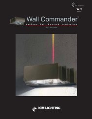
Down Model<br />
The Wall Commander - <strong>WC</strong>14 / <strong>WC</strong>18<br />
<strong>Install</strong>ation Instructions<br />
UP Model /<br />
UP-Down Model<br />
WARNING: Fixtures must be grounded in accordance with local codes or the National Electrical Code.<br />
! Failure to do so may result in serious personal injury.<br />
CAUTION: Up and Down models are not interchangeable. <strong>Install</strong>ing fixtures without regard to model designation<br />
(UP or DOWN) could result in water intrusion, fixture damage, or lens breakage. DO NOT operate<br />
luminaire with missing or damaged lens.<br />
MAINTENANCE: A regularly scheduled maintenance program should be established to retain optimum light<br />
output and reduce heat retention.<br />
CAUTION: All wiring should be done by a qualified electrician.<br />
KEEP THIS SHEET FOR FUTURE REFERENCE.<br />
ATTENTION: If your fixture is equipped with a multi-tap ballast and if no voltage was specified on the purchase<br />
order, the ballast has been wired for operation on a 277 volt circuit (347V in Canada). If other than 277 volts is<br />
required, i.e.; 120V, 208V, or 240V, connect incoming voltage lead to selected voltage lead on ballast. Cap off all<br />
unused voltage leads.<br />
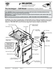
Tools Required: ❑ Flat Blade Screwdriver ❑ G" Socket ❑ Torque Wrench w/ 3" Extension<br />
❑ Silicone Sealant<br />
❑ Rope Caulking (provided)<br />
<strong>Install</strong>ation Instructions:<br />
Rope Caulk<br />
(Supplied)<br />
!<br />
<strong>WC</strong>14 Mounting Plate<br />
Shown<br />
Make certain electrical supply is OFF before starting installation.<br />
J-Box (By Others)<br />
<strong>WC</strong>14 Mounting Plate<br />
Shown<br />
Mounting Bolts For Housing<br />
(Supplied)<br />
1. <strong>Install</strong> mounting bolts through back-side of mounting<br />
plate making sure bolt heads seat in recessed hex.<br />
Important! Silicone sealant or rope caulk must be<br />
installed between mounting plate and mounting<br />
surface.<br />
Level<br />
2. <strong>WC</strong>14 - Fixture Wt.: 23 lbs. Attach mounting plate to<br />
any 4" J-Box (by others), with two (2) 8 /32" screws<br />
(supplied) or to wall surface with two (2) J" screws (by<br />
others), attached to anchors (supplied by others).<br />
<strong>WC</strong>18 - Fixture Wt.: 52 lbs. Use mounting plate as<br />
drilling template for (4) J" anchors (by others). Secure<br />
with (4) J" mounting bolts (by others) and tighten to 5-<br />
8 ft. lbs.<br />
3. Make sure the mounting bolts on the mounting plate<br />
are level and that the nuts are flush with the ends of the<br />
mounting bolts after plate is installed. Inspect seal<br />
between mounting plate and wall/mounting surface.<br />
Add RTV, if needed to assure a seal.<br />
2/27/06 Status 1 ECN 4496 P/N 95739
The Wall Commander - <strong>WC</strong>14 / <strong>WC</strong>18 <strong>Install</strong>ation Instructions<br />
Thumb<br />
Latches<br />
a.<br />
c.<br />
b.<br />
4. Open fixture by pushing on the two (2) thumb latches<br />
and gently swing open the lens frame. Remove lens<br />
frame from housing by lifting up and out of the rear<br />
hinge brackets.<br />
5. a. Unlatch the reflector assembly by pulling it down at<br />
front.<br />
b. Support the reflector and allow it to swing down.<br />
c. Remove reflector down and out, to remove.<br />
6. Hold fixture with both hands and guide keyhole slots<br />
(on back of fixture housing) onto mounting plate<br />
studs, then slide fixture down. Check to make sure<br />
fixture is level. Tighten nuts to 5-8 ft.-lbs.<br />
7. Connect fixture wires with disconnect plug to field<br />
wires observing polarity, i.e.; green-to-ground, whiteto-common<br />
& black-to-voltage. Tuck all leads into<br />
J-Box (by others).<br />
8. Join the disconnect plugs between the power lead-in<br />
and the ballast assembly.<br />
9. Hold the reflector close enough to join the<br />
disconnect plug halves between the socket and<br />
ballast assembly.<br />
Page 2 <strong>Kim</strong> <strong>Lighting</strong> • 16555 E. Gale Ave. • P.O. Box 60080 • City of Industry, CA 91716-0080 • 626/968-5666 • FAX 626/330-3861
The Wall Commander - <strong>WC</strong>14 / <strong>WC</strong>18 <strong>Install</strong>ation Instructions<br />
Slot<br />
Socket<br />
Lamp<br />
Tab<br />
Top View of Picture<br />
10. <strong>Install</strong> reflector by inserting tab into slot and lift up to<br />
engage ball stud into receptacle. Swing reflector into<br />
housing and push making sure no wires are pinched.<br />
WARNING:<br />
The H.I.D. / Fluorescent fixture utilizes a lamp that may<br />
contain mercury. For information on disposal of lamp,<br />
go to website: www.lamprecycle.org<br />
12. Insert lens frame into the hinge brackets. Close lens<br />
frame. Make sure both thumb latches engage to<br />
secure lens frame.<br />
11. Screw the proper lamp (as per fixture label) into the<br />
socket and tighten the lamp sufficiently to ensure a<br />
vibration-safe installation. After tightening, gently<br />
adjust both horizontal and vertical lamp positions so<br />
the lamp is in line with the lamp holder and centered<br />
in the reflector. NOTE: This is important for<br />
photometric performance in general and<br />
extremely important for the Ray Option, if<br />
equipped.<br />
MAINTENANCE INSTRUCTIONS:<br />
! Make certain electrical supply is OFF before<br />
beginning maintenance procedure.<br />
1. A regularly scheduled maintenance program should<br />
be established to retain optimum light output and<br />
reduce heat retention. To prevent UP model<br />
fixtures from overheating, lenses must be kept<br />
clean and free of dirt, dust, leaves, trash and<br />
mineral deposits from water regularly. Dusting<br />
with a soft, clean, dry cloth is normally sufficient for<br />
the reflector. Do Not use alkaline or acid cleaners<br />
on reflector surfaces.<br />
2. Any accumulation of dust or dirt should be removed<br />
regularly from both sides of the lens during relamping<br />
(using ammonia water).<br />
DOWN Models Only:<br />
To Remove Lens Clip:<br />
Insert tip of a large flat blade<br />
screwdriver under the lens clip<br />
legs and twist to remove.<br />
DOWN Models Only:<br />
To <strong>Install</strong> Lens Clip:<br />
Use small block of wood and tap on<br />
clips until the spring legs open to half<br />
their depth.<br />
Removing and Replacing of Glass Lens:<br />
DOWN Models: (Ref. Illustrations above)<br />
1. In the event the glass lens should need replacing, remove the lens frame and lay it on a padded surface.<br />
2. Insert the tip of a large flat blade screwdriver under the lens clip legs and twist to remove (see diagram above).<br />
3. Remove all the broken pieces of glass and make sure no glass fragments remain on top of the lens gasket.<br />
4. Lay the new lens on top of gasket and install the new lens clips by applying pressure, first by fingers and then using a<br />
small block of wood and tapping on clips until the spring legs open to half their depth (see diagram above).<br />
5. Attach lens frame to housing, close. Make sure both thumb latches engage to secure lens frame.<br />
UP Models: Because the lens is sealed at the factory, the housing assembly will need to be replaced. (Consult <strong>Kim</strong><br />
<strong>Lighting</strong> Customer Services.)<br />
Page 3 <strong>Kim</strong> <strong>Lighting</strong> • 16555 E. Gale Ave. • P.O. Box 60080 • City of Industry, CA 91716-0080 • 626/968-5666 • FAX 626/330-3861
The Wall Commander - <strong>WC</strong>14 / <strong>WC</strong>18 <strong>Install</strong>ation Instructions<br />
KIM LIGHTING LIMITED WARRANTY<br />
When installed in accordance with <strong>Kim</strong> <strong>Install</strong>ation Instructions and accepted trade practices, the following<br />
shall apply:<br />
General Product Limited Warranty Coverage<br />
All material and component parts used in the manufacture of <strong>Kim</strong> Products, are warranted to be free from<br />
defects of material and/or workmanship for a period of 1 year from date of sale. with the following exceptions:<br />
Auxiliary Equipment<br />
All auxiliary equipment (such as lamps, ballasts, and transformers) provided by and/or included in <strong>Kim</strong><br />
Products shall carry the component manufacturer's warranty.<br />
Copper and Bronze Landscape Components<br />
Copper and Bronze Landscape fixture components shall be warranted against defects of material and/or<br />
workmanship, and failure due to corrosion, for a period of 25 years from date of sale.<br />
Composite In-Grade Components<br />
Composite In-Grade fixture components installed below grade, shall be warranted against defects of material<br />
and/or workmanship, and failure due to corrosion, for a period of 7 years from date of sale.<br />
Aluminum Landscape Components<br />
Aluminum Landscape fixture components not in direct contact with soil, shall be warranted against defects of<br />
material and/or workmanship for a period of 3 years from date of sale. Aluminum fixture components in direct<br />
contact with soil shall be warranted from defects of material and failure from corrosion for a period of 1 year<br />
from date of sale.<br />
Limit of Liability and General Conditions<br />
Only products which are installed, used and maintained in accordance with applicable <strong>Kim</strong> instructions,<br />
specifications and accepted trade practices, are covered by the <strong>Kim</strong> Warranty. During the warranty period,<br />
with proof of purchase, <strong>Kim</strong> will repair or replace with the same or similar product, at <strong>Kim</strong>'s option, without<br />
charge. Labor costs are the owner's responsibility and are excluded from this warranty. This warranty is void<br />
if the product is modified, tampered with, misapplied, poorly installed, improperly maintained, or subjected to<br />
abnormal conditions.<br />
Repair or replacement as provided under this warranty is the exclusive remedy of the purchaser. This<br />
warranty is in lieu of all other warranties, expressed or implied, including any implied warranty of fitness for a<br />
particular application. <strong>Kim</strong> <strong>Lighting</strong> shall not be liable to the purchaser for indirect or consequential damages.<br />
How may we serve you better?<br />
Please let us know. Visit our website at:<br />
www.kimlighting.com<br />
Your concerns matters to us.<br />
Page 4 <strong>Kim</strong> <strong>Lighting</strong> • 16555 E. Gale Ave. • P.O. Box 60080 • City of Industry, CA 91716-0080 • 626/968-5666 • FAX 626/330-3861