ADB Series Air Disc Brakes - Nsbshadow.com
ADB Series Air Disc Brakes - Nsbshadow.com
ADB Series Air Disc Brakes - Nsbshadow.com

Create successful ePaper yourself
Turn your PDF publications into a flip-book with our unique Google optimized e-Paper software.
Maintenance Manual 4M<br />
<strong>ADB</strong> <strong>Series</strong> <strong>Air</strong> <strong>Disc</strong> <strong>Brakes</strong><br />
Revised 04-05
Service Notes<br />
About This Manual<br />
This manual provides instructions for Meritor air disc brakes.<br />
Before You Begin<br />
1. Read and understand all instructions and procedures before<br />
you begin to service <strong>com</strong>ponents.<br />
2. Read and observe all Warning and Caution hazard alert<br />
messages in this publication. They provide information that can<br />
help prevent serious personal injury, damage to <strong>com</strong>ponents,<br />
or both.<br />
3. Follow your <strong>com</strong>pany’s maintenance and service, installation,<br />
and diagnostics guidelines.<br />
4. Use special tools when required to help avoid serious personal<br />
injury and damage to <strong>com</strong>ponents.<br />
ArvinMeritor’s Customer Service Center<br />
Call ArvinMeritor’s Customer Service Center at 800-535-5560.<br />
Technical Electronic Library on CD<br />
The DriveTrain Plus by ArvinMeritor Technical Electronic Library<br />
on CD contains product and service information for most Meritor<br />
and Meritor WABCO products. $20. Specify TP-9853.<br />
How to Obtain Tools and Supplies<br />
Specified in This Manual<br />
Call ArvinMeritor’s Commercial Vehicle Aftermarket at<br />
888-725-9355 to obtain Meritor tools and supplies.<br />
Hazard Alert Messages and Torque<br />
Symbols<br />
WARNING<br />
A Warning alerts you to an instruction or procedure that you<br />
must follow exactly to avoid serious personal injury and<br />
damage to <strong>com</strong>ponents.<br />
CAUTION<br />
A Caution alerts you to an instruction or procedure that you<br />
must follow exactly to avoid damage to <strong>com</strong>ponents.<br />
@ This symbol alerts you to tighten fasteners to a specified torque<br />
value.<br />
How to Obtain Additional Maintenance<br />
and Service Information<br />
On the Web<br />
Visit the DriveTrain Plus by ArvinMeritor Tech Library at<br />
arvinmeritor.<strong>com</strong> to easily access product and service information.<br />
The Library also offers an interactive and printable Literature Order<br />
Form.<br />
Information contained in this publication was in effect at the time the publication was<br />
approved for printing and is subject to change without notice or liability. Meritor Heavy<br />
Vehicle Systems, LLC, reserves the right to revise the information presented or to<br />
discontinue the production of parts described at any time.<br />
Meritor Maintenance Manual 4M (Revised 04-05)
Contents<br />
pg.<br />
i Asbestos and Non-Asbestos Fibers<br />
1 Section 1: Exploded Views<br />
4 Section 2: Introduction<br />
Overview<br />
Model Code<br />
Description<br />
How the Brake Functions<br />
5 Section 3: Caliper<br />
Removal<br />
Caliper<br />
6 Installation<br />
Caliper<br />
7 Calipers with Helper Springs<br />
9 Section 4: Caliper Bushings<br />
Inspection<br />
Caliper Bushings<br />
10 Removal<br />
Caliper Bushings<br />
Inspection<br />
Caliper Bores<br />
11 Installation<br />
Caliper Bushing Kits and Special Tools<br />
12 Prepare to Install the Bushings<br />
Install the Outer Bushings<br />
Install the Inner Bushings<br />
14 Section 5: Caliper/Piston Boot and O-Ring<br />
Removal<br />
Caliper/Piston Boot and O-Ring<br />
16 Replace<br />
Boot and O-Ring<br />
17 Installation<br />
Caliper/Piston Boot and O-Ring<br />
20 Section 6: Automatic Slack Adjuster<br />
Removal<br />
Automatic Slack Adjuster<br />
21 Installation<br />
Automatic Slack Adjuster<br />
24 Section 7: Camshaft<br />
Removal<br />
Camshaft<br />
26 Installation<br />
Camshaft<br />
27 Caliper<br />
pg.<br />
28 Section 8: <strong>Disc</strong> (Rotor)<br />
Inspection<br />
<strong>Disc</strong> or Rotor<br />
29 Measuring the Thickness of the <strong>Disc</strong> or Rotor<br />
Removal<br />
<strong>Disc</strong> or Rotor<br />
Front Non-Drive Steering Axles and Trailer Axles<br />
30 Drive Axles<br />
32 Installation<br />
Advisory Label TP-0503<br />
<strong>Disc</strong> or Rotor<br />
34 Section 9: Torque Plate and Bushings<br />
Inspection<br />
Torque Plate<br />
Torque Plate Bushings<br />
Removal<br />
Torque Plate Bushings<br />
35 Torque Plate<br />
Installation<br />
Torque Plate<br />
Tighten the Torque Plate<br />
Torque Plate Bushings<br />
37 Section 10: Reline the <strong>Brakes</strong><br />
Check<br />
Lining Wear<br />
Removal<br />
Shoes and Linings or Pads<br />
41 Installation<br />
Shoes and Linings (Pads)<br />
44 Section 11: Adjust the <strong>Brakes</strong><br />
Check and Adjust<br />
Brake Chamber Push Rod Stroke and Adjust the Clevis<br />
Position<br />
Brake Slack Adjuster Position (BSAP) Method<br />
Automatic Slack Adjuster Templates<br />
Measure the Slack Adjuster<br />
45 Install a Threaded Clevis<br />
47 Measuring and Adjusting the Chamber Stroke<br />
Measuring the Initial and In-Service Free Stroke Without a<br />
Template<br />
48 Measuring the In-Service Free Stroke with a Template<br />
Adjusting the Stroke<br />
49 Commercial Vehicle Safety Alliance (CVSA) Guidelines to<br />
Measure Push Rod Travel (Adjusted Chamber Stroke)<br />
50 Alternate Method for Determining Push Rod Travel<br />
(Adjusted Chamber Stroke)<br />
Commercial Vehicle Safety Alliance (CVSA) North<br />
American Out-of-Service Criteria Reference Charts
Contents<br />
Section 12: Prepare Parts for Assembly<br />
Clean, Dry and Inspect Parts<br />
Dry and Inspect the Parts<br />
52 Section 13: Lubrication and Maintenance<br />
Lubrication<br />
Automatic Slack Adjuster<br />
Caliper<br />
53 Maintenance<br />
Minor Inspections<br />
55 Major Inspections<br />
57 Section 14: Diagnostics<br />
Troubleshooting<br />
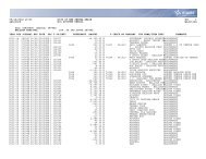
61 Section 15: Specifications<br />
Torque Specifications<br />
pg. 51
Asbestos and Non-Asbestos Fibers<br />
Figure 0.1<br />
ASBESTOS FIBERS WARNING<br />
The following procedures for servicing brakes are re<strong>com</strong>mended to reduce exposure to<br />
asbestos fiber dust, a cancer and lung disease hazard. Material Safety Data Sheets are<br />
available from ArvinMeritor.<br />
Hazard Summary<br />
Because some brake linings contain asbestos, workers who service brakes must understand the<br />
potential hazards of asbestos and precautions for reducing risks. Exposure to airborne asbestos<br />
dust can cause serious and possibly fatal diseases, including asbestosis (a chronic lung disease)<br />
and cancer, principally lung cancer and mesothelioma (a cancer of the lining of the chest or<br />
abdominal cavities). Some studies show that the risk of lung cancer among persons who smoke<br />
and who are exposed to asbestos is much greater than the risk for non-smokers. Symptoms of<br />
these diseases may not be<strong>com</strong>e apparent for 15, 20 or more years after the first exposure to<br />
asbestos.<br />
Accordingly, workers must use caution to avoid creating and breathing dust when servicing<br />
brakes. Specific re<strong>com</strong>mended work practices for reducing exposure to asbestos dust follow.<br />
Consult your employer for more details.<br />
Re<strong>com</strong>mended Work Practices<br />
1. Separate Work Areas. Whenever feasible, service brakes in a separate area away from other<br />
operations to reduce risks to unprotected persons. OSHA has set a maximum allowable level of<br />
exposure for asbestos of 0.1 f/cc as an 8-hour time-weighted average and 1.0 f/cc averaged over<br />
a 30-minute period. Scientists disagree, however, to what extent adherence to the maximum<br />
allowable exposure levels will eliminate the risk of disease that can result from inhaling asbestos<br />
dust. OSHA requires that the following sign be posted at the entrance to areas where exposures<br />
exceed either of the maximum allowable levels:<br />
DANGER: ASBESTOS<br />
CANCER AND LUNG DISEASE HAZARD<br />
AUTHORIZED PERSONNEL ONLY<br />
RESPIRATORS AND PROTECTIVE CLOTHING<br />
ARE REQUIRED IN THIS AREA.<br />
2. Respiratory Protection. Wear a respirator equipped with a high-efficiency (HEPA) filter<br />
approved by NIOSH or MSHA for use with asbestos at all times when servicing brakes, beginning<br />
with the removal of the wheels.<br />
3. Procedures for Servicing <strong>Brakes</strong>.<br />
a. Enclose the brake assembly within a negative pressure enclosure. The enclosure should be<br />
equipped with a HEPA vacuum and worker arm sleeves. With the enclosure in place, use the<br />
HEPA vacuum to loosen and vacuum residue from the brake parts.<br />
b. As an alternative procedure, use a catch basin with water and a biodegradable, nonphosphate,<br />
water-based detergent to wash the brake drum or rotor and other brake parts.<br />
The solution should be applied with low pressure to prevent dust from be<strong>com</strong>ing airborne.<br />
Allow the solution to flow between the brake drum and the brake support or the brake rotor<br />
and caliper. The wheel hub and brake assembly <strong>com</strong>ponents should be thoroughly wetted to<br />
suppress dust before the brake shoes or brake pads are removed. Wipe the brake parts<br />
clean with a cloth.<br />
c. If an enclosed vacuum system or brake washing equipment is not available, employers may<br />
adopt their own written procedures for servicing brakes, provided that the exposure levels<br />
associated with the employer’s procedures do not exceed the levels associated with the<br />
enclosed vacuum system or brake washing equipment. Consult OSHA regulations for more<br />
details.<br />
d. Wear a respirator equipped with a HEPA filter approved by NIOSH or MSHA for use with<br />
asbestos when grinding or machining brake linings. In addition, do such work in an area with<br />
a local exhaust ventilation system equipped with a HEPA filter.<br />
e. NEVER use <strong>com</strong>pressed air by itself, dry brushing, or a vacuum not equipped with a HEPA<br />
filter when cleaning brake parts or assemblies. NEVER use carcinogenic solvents,<br />
flammable solvents, or solvents that can damage brake <strong>com</strong>ponents as wetting agents.<br />
4. Cleaning Work Areas. Clean work areas with a vacuum equipped with a HEPA filter or by wet<br />
wiping. NEVER use <strong>com</strong>pressed air or dry sweeping to clean work areas. When you empty<br />
vacuum cleaners and handle used rags, wear a respirator equipped with a HEPA filter approved<br />
by NIOSH or MSHA for use with asbestos. When you replace a HEPA filter, wet the filter with a fine<br />
mist of water and dispose of the used filter with care.<br />
5. Worker Clean-Up. After servicing brakes, wash your hands before you eat, drink or smoke.<br />
Shower after work. Do not wear work clothes home. Use a vacuum equipped with a HEPA filter to<br />
vacuum work clothes after they are worn. Launder them separately. Do not shake or use<br />
<strong>com</strong>pressed air to remove dust from work clothes.<br />
6. Waste Disposal. Dispose of discarded linings, used rags, cloths and HEPA filters with care,<br />
such as in sealed plastic bags. Consult applicable EPA, state and local regulations on waste<br />
disposal.<br />
Regulatory Guidance<br />
References to OSHA, NIOSH, MSHA, and EPA, which are regulatory agencies in the United States,<br />
are made to provide further guidance to employers and workers employed within the United<br />
States. Employers and workers employed outside of the United States should consult the<br />
regulations that apply to them for further guidance.<br />
NON-ASBESTOS FIBERS WARNING<br />
The following procedures for servicing brakes are re<strong>com</strong>mended to reduce exposure to<br />
non-asbestos fiber dust, a cancer and lung disease hazard. Material Safety Data<br />
Sheets are available from ArvinMeritor.<br />
Hazard Summary<br />
Most recently manufactured brake linings do not contain asbestos fibers. These brake linings may<br />
contain one or more of a variety of ingredients, including glass fibers, mineral wool, aramid fibers,<br />
ceramic fibers and silica that can present health risks if inhaled. Scientists disagree on the extent<br />
of the risks from exposure to these substances. Nonetheless, exposure to silica dust can cause<br />
silicosis, a non-cancerous lung disease. Silicosis gradually reduces lung capacity and efficiency<br />
and can result in serious breathing difficulty. Some scientists believe other types of non-asbestos<br />
fibers, when inhaled, can cause similar diseases of the lung. In addition, silica dust and ceramic<br />
fiber dust are known to the State of California to cause lung cancer. U.S. and international<br />
agencies have also determined that dust from mineral wool, ceramic fibers and silica are potential<br />
causes of cancer.<br />
Accordingly, workers must use caution to avoid creating and breathing dust when servicing<br />
brakes. Specific re<strong>com</strong>mended work practices for reducing exposure to<br />
non-asbestos dust follow. Consult your employer for more details.<br />
Re<strong>com</strong>mended Work Practices<br />
1. Separate Work Areas. Whenever feasible, service brakes in a separate area away from other<br />
operations to reduce risks to unprotected persons.<br />
2. Respiratory Protection. OSHA has set a maximum allowable level of exposure for silica of 0.1<br />
mg/m 3 as an 8-hour time-weighted average. Some manufacturers of non-asbestos brake linings<br />
re<strong>com</strong>mend that exposures to other ingredients found in non-asbestos brake linings be kept<br />
below 1.0 f/cc as an 8-hour time-weighted average. Scientists disagree, however, to what extent<br />
adherence to these maximum allowable exposure levels will eliminate the risk of disease that can<br />
result from inhaling non-asbestos dust.<br />
Therefore, wear respiratory protection at all times during brake servicing, beginning with the<br />
removal of the wheels. Wear a respirator equipped with a high-efficiency (HEPA) filter<br />
approved by NIOSH or MSHA, if the exposure levels may exceed OSHA or manufacturers’<br />
re<strong>com</strong>mended maximum levels. Even when exposures are expected to be within the maximum<br />
allowable levels, wearing such a respirator at all times during brake servicing will help minimize<br />
exposure.<br />
3. Procedures for Servicing <strong>Brakes</strong>.<br />
a. Enclose the brake assembly within a negative pressure enclosure. The enclosure should be<br />
equipped with a HEPA vacuum and worker arm sleeves. With the enclosure in place, use the<br />
HEPA vacuum to loosen and vacuum residue from the brake parts.<br />
b. As an alternative procedure, use a catch basin with water and a biodegradable, nonphosphate,<br />
water-based detergent to wash the brake drum or rotor and other brake parts.<br />
The solution should be applied with low pressure to prevent dust from be<strong>com</strong>ing airborne.<br />
Allow the solution to flow between the brake drum and the brake support or the brake rotor<br />
and caliper. The wheel hub and brake assembly <strong>com</strong>ponents should be thoroughly wetted to<br />
suppress dust before the brake shoes or brake pads are removed. Wipe the brake parts<br />
clean with a cloth.<br />
c. If an enclosed vacuum system or brake washing equipment is not available, carefully clean<br />
the brake parts in the open air. Wet the parts with a solution applied with a pump-spray<br />
bottle that creates a fine mist. Use a solution containing water, and, if available, a<br />
biodegradable, non-phosphate, water-based detergent. The wheel hub and brake assembly<br />
<strong>com</strong>ponents should be thoroughly wetted to suppress dust before the brake shoes or brake<br />
pads are removed. Wipe the brake parts clean with a cloth.<br />
d. Wear a respirator equipped with a HEPA filter approved by NIOSH or MSHA when grinding or<br />
machining brake linings. In addition, do such work in an area with a local exhaust ventilation<br />
system equipped with a HEPA filter.<br />
e. NEVER use <strong>com</strong>pressed air by itself, dry brushing, or a vacuum not equipped with a HEPA<br />
filter when cleaning brake parts or assemblies. NEVER use carcinogenic solvents,<br />
flammable solvents, or solvents that can damage brake <strong>com</strong>ponents as wetting agents.<br />
4. Cleaning Work Areas. Clean work areas with a vacuum equipped with a HEPA filter or by wet<br />
wiping. NEVER use <strong>com</strong>pressed air or dry sweeping to clean work areas. When you empty<br />
vacuum cleaners and handle used rags, wear a respirator equipped with a HEPA filter approved<br />
by NIOSH or MSHA, to minimize exposure. When you replace a HEPA filter, wet the filter with a<br />
fine mist of water and dispose of the used filter with care.<br />
5. Worker Clean-Up. After servicing brakes, wash your hands before you eat, drink or smoke.<br />
Shower after work. Do not wear work clothes home. Use a vacuum equipped with a HEPA filter to<br />
vacuum work clothes after they are worn. Launder them separately. Do not shake or use<br />
<strong>com</strong>pressed air to remove dust from work clothes.<br />
6. Waste Disposal. Dispose of discarded linings, used rags, cloths and HEPA filters with care,<br />
such as in sealed plastic bags. Consult applicable EPA, state and local regulations on waste<br />
disposal.<br />
Regulatory Guidance<br />
References to OSHA, NIOSH, MSHA, and EPA, which are regulatory agencies in the United States,<br />
are made to provide further guidance to employers and workers employed within the United<br />
States. Employers and workers employed outside of the United States should consult the<br />
regulations that apply to them for further guidance.<br />
Meritor Maintenance Manual 4M (Revised 04-05)<br />
i
1 Exploded Views<br />
1 Exploded Views<br />
Figure 1.1<br />
4<br />
5<br />
6<br />
7<br />
8<br />
9<br />
10<br />
EXTENDED DESIGN<br />
COMPONENTS<br />
41<br />
18<br />
43<br />
11<br />
42<br />
3<br />
40<br />
18<br />
1<br />
2<br />
39<br />
CALIPER CASTING<br />
NUMBER LOCATION<br />
12<br />
13<br />
14<br />
15 16<br />
AIR DISC BRAKE<br />
17<br />
30<br />
29<br />
19<br />
18<br />
20<br />
21<br />
22 25<br />
36<br />
31<br />
38<br />
32<br />
26<br />
35<br />
34<br />
33<br />
28<br />
37 23<br />
24 27<br />
4001532a
1 Exploded Views<br />
Item<br />
Description<br />
1 Caliper<br />
2 Bushing — Caliper Slide Pin, Outer<br />
3 Fitting — Grease<br />
4 Snap Ring — Seal Retaining<br />
5 Seal Assembly — Brake Piston End<br />
6 Snap Ring — Spring Retaining<br />
7 Bushing — Camshaft Inner Pilot<br />
8 Spring — Piston Return<br />
9 Piston — Brake Shoe<br />
10 Boot — Caliper/Piston<br />
11 O-Ring — Brake Piston to Caliper<br />
12 Nut — Actuator<br />
13 Camshaft<br />
14 Washer — Camshaft Thrust<br />
15 O-Ring<br />
16 Cap — Camshaft<br />
17 Fitting — Grease<br />
18 Bushing — Camshaft, Two Used with Extended<br />
Camshaft Cap<br />
19 Seal — Camshaft Cap<br />
20 Dust Cover — Camshaft Retaining<br />
21 Snap Ring — Camshaft Retaining<br />
22 Bracket — <strong>Air</strong> Chamber<br />
23 Washer — Chamber Bracket Capscrew<br />
24 Capscrew — Chamber Bracket<br />
25 Automatic Slack Adjuster<br />
26 Washer — Slack Adjuster<br />
27 Snap Ring — Slack Adjuster<br />
28 Slide Pin — Caliper<br />
29 Torque Plate<br />
30 Bushing — Torque Plate<br />
31 Spring — Slide Pin Retainer<br />
32 Washer — Slide Pin Retainer<br />
33 Slide Pin Retainer<br />
34 Nut — Slide PIn Retainer<br />
Item<br />
Description<br />
35 Cotter Pin — Slide Pin Retainer<br />
36 <strong>Disc</strong>, Rotor, Vented Type<br />
37 Inner Shoe and Lining Assembly<br />
38 Outer Shoe and Lining Assembly<br />
39 Bushing — Caliper Slide Pin, Inner<br />
40 Fitting — Pressure Relief<br />
41 Extended Camshaft, Optional for Certain<br />
Applications<br />
42 Extended Cap — Camshaft, Optional for Certain<br />
Applications<br />
43 Fitting — Grease, Used with Extended Camshaft<br />
Cap<br />
Meritor Maintenance Manual 4M (Revised 04-05)<br />
1
1 Exploded Views<br />
Figure 1.2<br />
30<br />
AIR DISC BRAKE CUTAWAY VIEW<br />
1<br />
2<br />
5<br />
28<br />
29<br />
3<br />
6<br />
7<br />
8<br />
9<br />
4<br />
10<br />
11<br />
12<br />
OUTBOARD<br />
INBOARD<br />
13<br />
14<br />
15<br />
27<br />
16<br />
26<br />
25<br />
24<br />
23<br />
22<br />
21<br />
20<br />
19<br />
17<br />
18<br />
4001533a<br />
2 Meritor Maintenance Manual 4M (Revised 04-05)
1 Exploded Views<br />
Item<br />
Description<br />
1 O-Ring, on Units Manufactured from Late 1991<br />
to Present<br />
2 Caliper Bushing<br />
3 Caliper<br />
4 <strong>Air</strong> Chamber Bracket<br />
5 Washer<br />
6 Capscrew<br />
7 Outer Camshaft Cap Bushing<br />
8 Camshaft Cap Seal<br />
9 Camshaft Cap Dust Cover<br />
10 Snap Ring, Camshaft Retaining<br />
11 Automatic Slack Adjuster<br />
12 Outer Slack Adjuster Washer<br />
13 Camshaft<br />
14 Snap Ring, Slack Adjuster Retaining<br />
15 Camshaft/Cap Thrust Washer<br />
16 Camshaft Cap<br />
17 Camshaft Cap O-Ring<br />
18 Camshaft Nut<br />
19 Piston Return Spring<br />
20 Brake Piston<br />
21 Brake Piston/Caliper Seal, on Units<br />
Manufactured Before Late 1991<br />
22 Brake Piston/Caliper Boot<br />
23 Inner Spring Retainer/Camshaft Bushing<br />
24 Snap Ring, Spring Retaining<br />
25 Piston Seal and Snap Ring<br />
26 Inboard Shoe and Lining Pad<br />
27 Outboard Shoe and Lining Pad<br />
28 <strong>Disc</strong>, Rotor — Vented Type<br />
29 Slide Pin<br />
30 Torque Plate Bushing<br />
Meritor Maintenance Manual 4M (Revised 04-05)<br />
3
2 Introduction<br />
2 Introduction<br />
Overview<br />
Model Code<br />
The model codes and applications for Meritor air disc brakes are<br />
described in Figure 2.1. <strong>Air</strong> disc brake model <strong>ADB</strong> 1760 is available<br />
only on tandem drive axles with air suspensions.<br />
Figure 2.1<br />
FRONT BRAKE MODEL CODE<br />
WITH SOLID DISC TO 12,000 G.A.W.R.<br />
AIR DISC BRAKE<br />
NOMINAL 15"<br />
DIA. ROTOR<br />
FRONT, DRIVE AND TRAILER BRAKE<br />
MODEL CODE WITH VENTED DISC<br />
Single axles to 23,000 G.A.W.R.<br />
Tandem axles to 46,000 G.A.W.R.<br />
Single trailer axles to 23,000 G.A.W.R.<br />
Tandem trailer axles to 46,000 G.A.W.R.<br />
Front axles to 20,000 G.A.W.R.<br />
<strong>ADB</strong>-1560-1<br />
AIR DISC BRAKE<br />
NOMINAL 15"<br />
DIA. ROTOR<br />
<strong>ADB</strong>-1540-1<br />
CUSTOMER<br />
SPECIFICATION<br />
NOMINAL<br />
40 SQ. IN.<br />
LINING AREA<br />
CUSTOMER<br />
SPECIFICATION<br />
NOMINAL<br />
60 SQ. IN.<br />
LINING AREA<br />
4001534a<br />
How the Brake Functions<br />
When the brakes are applied, the push rod of the air chamber<br />
pushes the automatic slack adjuster that is mounted to the<br />
camshaft of the brake. The movement of the slack adjuster rotates<br />
the camshaft, which causes the camshaft nut to slide out along the<br />
camshaft.<br />
The nut pushes the piston and the inboard lining, pad, against the<br />
disc or rotor. The force of the inboard lining on the disc or rotor pulls<br />
the caliper in along the slide pins.<br />
The movement of the caliper places the outboard pad into contact<br />
with the disc or rotor. The result is clamping force on both sides of<br />
the disc or rotor. Figure 2.2.<br />
When the brakes are released, the piston return spring retracts the<br />
piston, which forces the nut back to its starting position. This action<br />
releases the clamping force on the disc or rotor.<br />
Figure 2.2<br />
OUTBOARD<br />
DISC, ROTOR —<br />
VENTED TYPE<br />
CALIPER<br />
AUTOMATIC<br />
SLACK<br />
ADJUSTER<br />
INBOARD<br />
Figure 2.1<br />
Description<br />
Meritor air disc brakes have the following features.<br />
An easily visible indicator for lining wear<br />
A caliper that pivots away from the disc (rotor) for quick shoe and<br />
lining (pad) changes<br />
A Meritor automatic slack adjuster<br />
A caliper that is sealed and lubricated to protect the <strong>com</strong>ponents<br />
that actuate the brake<br />
Standard service air chambers or air chambers with springs<br />
PISTON<br />
RETURN<br />
OUTBOARD SHOE SPRING<br />
NUT<br />
AND LINING PAD<br />
BRAKE PISTON<br />
INBOARD SHOE AND LINING PAD<br />
Figure 2.2<br />
POWER<br />
SHAFT<br />
4001535a<br />
4 Meritor Maintenance Manual 4M (Revised 04-05)
3 Caliper<br />
3 Caliper<br />
Hazard Alert Messages<br />
Read and observe all Warning and Caution hazard alert messages in<br />
this publication. They provide information that can help prevent<br />
serious personal injury, damage to <strong>com</strong>ponents, or both.<br />
WARNING<br />
To prevent serious eye injury, always wear safe eye protection<br />
when you perform vehicle maintenance or service.<br />
Figure 3.1<br />
TORQUE PLATE ARM<br />
Park the vehicle on a level surface. Block the wheels to<br />
prevent the vehicle from moving. Support the vehicle with<br />
safety stands. Do not work under a vehicle supported only by<br />
jacks. Jacks can slip and fall over. Serious personal injury and<br />
damage to <strong>com</strong>ponents can result.<br />
Removal<br />
Caliper<br />
1. Park the vehicle on a level surface and block the wheels.<br />
2. Remove all the air from the air system.<br />
3. Remove the air lines from the air chamber.<br />
WARNING<br />
Before you service a spring chamber, carefully follow the<br />
manufacturer’s instructions to <strong>com</strong>press and lock the spring to<br />
<strong>com</strong>pletely release the brake. Verify that no air pressure<br />
remains in the service chamber before you proceed. Sudden<br />
release of <strong>com</strong>pressed air can cause serious personal injury<br />
and damage to <strong>com</strong>ponents.<br />
Figure 3.1<br />
WARNING<br />
When you remove a clevis pin that has a spring on it, hold the<br />
spring with pliers. The spring can disengage from the clevis<br />
pin with enough force to cause serious personal injury.<br />
7. Remove both clevis pins from the slack adjuster.<br />
8. Remove the stud nuts that hold the air chamber to the bracket.<br />
Remove the air chamber. Figure 3.2.<br />
Figure 3.2<br />
4001536a<br />
4. If the vehicle has spring brakes, manually <strong>com</strong>press and lock<br />
the springs to release the brakes. You must check to ensure<br />
that no air pressure remains in the service halves of the air<br />
chambers.<br />
5. Remove the top slide pin. Temporarily raise the caliper into<br />
position over the disc (rotor). Figure 3.1.<br />
6. Install the top slide pin through the outboard caliper boss and<br />
into the torque plate to support the caliper.<br />
Figure 3.2<br />
4001537a<br />
Meritor Maintenance Manual 4M (Revised 04-05)<br />
5
3 Caliper<br />
9. Remove the cotter pin from the bottom slide pin retainer.<br />
Loosen the nut on the retainer. Figure 3.3.<br />
Figure 3.3<br />
Installation<br />
Caliper<br />
1. Remove dirt, paint or other material from the slide pins.<br />
2. Support the caliper while you align the bores in the top of the<br />
caliper and the torque plate. Install the top slide pin through the<br />
caliper and into the torque plate from the outboard side. Install<br />
the pin so that its threaded hole is toward the outboard side.<br />
Figure 3.4.<br />
Figure 3.4<br />
LOOSEN BOTTOM RETAINER NUT<br />
4001538a<br />
Figure 3.3<br />
WARNING<br />
Use a brass or synthetic mallet for assembly and disassembly<br />
procedures. Do not hit steel parts with a steel hammer. Pieces<br />
of a part can break off. Serious personal injury and damage to<br />
<strong>com</strong>ponents can result.<br />
10. Press the end of the retainer to release the slide pin. Pull the<br />
bottom slide pin out of the caliper and the torque plate. If you<br />
cannot press the retainer or remove the slide pin by hand, use<br />
the following procedures.<br />
A. Apply penetrating oil to help loosen the retainer. Turn the<br />
nut until the end of the retainer is below the top of the nut.<br />
Hit the nut with a brass or leather mallet to loosen the<br />
retainer.<br />
B. Install a slide hammer into the threaded hole in the end of<br />
the slide pin. If necessary, install an extension bar to the<br />
slide hammer for clearance.<br />
C. Press the end of the retainer to release the slide pin. Use<br />
the knocker to loosen and remove the pin.<br />
11. Pull the bottom of the caliper away from the disc (rotor) and<br />
support the caliper. Figure 3.4.<br />
12. Remove the top slide pin using the same procedures you used<br />
to remove the bottom slide pin. Lift the caliper away from the<br />
disc (rotor).<br />
Figure 3.4<br />
SLIDE HAMMER<br />
4001539a<br />
6 Meritor Maintenance Manual 4M (Revised 04-05)
3 Caliper<br />
NOTE: The notch in the slide pin must be aligned with the slide pin<br />
retainer.<br />
3. The notch in the slide pin retainer must be toward the bore for<br />
the slide pin. The notches in the retainer and the slide pin must<br />
engage when you install the slide pin. Figure 3.5.<br />
Figure 3.7<br />
Tighten the retainer nut to 60-80 lb-ft<br />
(81-108 N•m) and install the cotter pin.<br />
TORQUE<br />
PLATE<br />
Figure 3.5<br />
Align<br />
notches.<br />
Figure 3.7<br />
CALIPER INBOARD BOSS<br />
VENTED DISC<br />
9/16" (14.3 MM)<br />
SOLID DISC<br />
5/8" (15.9 MM)<br />
4001542a<br />
Figure 3.5<br />
4. Push down the retainer and push in the slide pin. Figure 3.6.<br />
The retainer will snap out when the notches engage.<br />
Figure 3.6<br />
SLIDE PIN<br />
RETAINER<br />
AND NUT<br />
4001540a<br />
6. Check for grease on the slide pin retainer threads. Wipe clean,<br />
if necessary. Tighten the nut on the slide pin retainer to 60 lb-ft<br />
(81 Nm). Figure 3.7. @<br />
7. Tighten the nut to the next slot and install a new cotter pin<br />
through the nut and retainer. DO NOT exceed 80 lb-ft<br />
(108 Nm). @<br />
8. Repeat Steps 2-7 to install the bottom slide pin.<br />
Calipers with Helper Springs<br />
1. Support the caliper.<br />
2. Install one spring on each slide pin between the torque plate<br />
and the OUTBOARD caliper boss. Figure 3.8.<br />
3. Position the large end of the helper spring toward the torque<br />
plate.<br />
SLIDE<br />
PIN<br />
USING THE<br />
SLIDE HAMMER<br />
4001541a<br />
4. Install the slide pin with its threaded hole OUTBOARD.<br />
5. Install the pin through the caliper and helper spring into the<br />
torque plate.<br />
Figure 3.6<br />
5. To correctly install the slide pin, the pin must extend past the<br />
inboard boss of the caliper, as shown in Figure 3.7.<br />
Meritor Maintenance Manual 4M (Revised 04-05)<br />
7
3 Caliper<br />
Figure 3.8<br />
Align<br />
bores.<br />
Support<br />
here.<br />
Install helper<br />
spring here.<br />
CALIPER<br />
OUTBOARD BOSS<br />
SLIDE<br />
PIN<br />
TORQUE PLATE<br />
Tighten the retainer nut to<br />
60-80 lb-ft (81-108 N•m)<br />
and install the cotter pin.<br />
CALIPER HELPER SPRING<br />
LARGE END INBOARD<br />
VENTED DISC<br />
APPROXIMATELY<br />
9/16" (14.3 MM)<br />
SOLID DISC<br />
APPROXIMATELY<br />
6/8" (15.9 MM)<br />
4001543a<br />
Figure 3.8<br />
8 Meritor Maintenance Manual 4M (Revised 04-05)
4 Caliper Bushings<br />
4 Caliper Bushings<br />
Hazard Alert Messages<br />
Read and observe all Warning and Caution hazard alert messages in<br />
this publication. They provide information that can help prevent<br />
serious personal injury, damage to <strong>com</strong>ponents, or both.<br />
WARNING<br />
To prevent serious eye injury, always wear safe eye protection<br />
when you perform vehicle maintenance or service.<br />
Inspection<br />
Caliper Bushings<br />
CAUTION<br />
When a caliper bushing is worn, you must replace all four<br />
bushings in the caliper with a new set of caliper bushings. Do<br />
not install new bushings with old bushings in the same caliper.<br />
Slide pin sticking and binding will occur that can result in<br />
premature lining wear.<br />
When the Caliper Is Mounted onto the Vehicle<br />
Use a pin gauge (J-34064-54) to check for bushing wear. When<br />
the gauge fits between the slide pin and bushing, the slide pin or<br />
bushing is worn and must be replaced. Figure 4.1. To obtain the<br />
pin gauge, contact SPX Kent-Moore at 800-328-6657.<br />
When the Caliper Is Removed from the Vehicle<br />
1. Clean and inspect the bushings for damage.<br />
CAUTION<br />
If a slide pin wears <strong>com</strong>pletely through a caliper bushing,<br />
remove the bushing and inspect the caliper bore for wear. If<br />
the caliper bore is worn, you must replace the caliper. A worn<br />
caliper bore can cause brake drag. Damage to <strong>com</strong>ponents<br />
can result.<br />
2. Use a plug gauge (J-34064-53) to check for bushing wear.<br />
When the gauge fits into the bushing, the bushing is worn and<br />
must be replaced. Figure 4.2. Refer to the procedure in this<br />
section. To obtain the plug gauge, contact SPX Kent-Moore at<br />
800-328-6657.<br />
Figure 4.2<br />
If you do not have a plug gauge, measure the inner diameter of<br />
all four caliper bushings at three locations. Figure 4.3. Replace<br />
all four bushings if the diameter of any bushing exceeds<br />
1.052-inches (26.72 mm).<br />
Figure 4.1<br />
J-34064-53<br />
4001545a<br />
Figure 4.2<br />
J-34064-54<br />
4001544a<br />
Figure 4.1<br />
Meritor Maintenance Manual 4M (Revised 04-05)<br />
9
4 Caliper Bushings<br />
Figure 4.3<br />
Figure 4.4<br />
Bushing I.D. must not<br />
be over 1.052" (26.72 mm).<br />
1<br />
2<br />
SUPPORT<br />
MEASURE AT THREE<br />
LOCATIONS<br />
3<br />
4001546a<br />
Figure 4.4<br />
BUSHING<br />
4001547a<br />
Figure 4.3<br />
Removal<br />
Caliper Bushings<br />
WARNING<br />
Use a brass or synthetic mallet for assembly and disassembly<br />
procedures. Do not hit steel parts with a steel hammer. Pieces<br />
of a part can break off. Serious personal injury and damage to<br />
<strong>com</strong>ponents can result.<br />
1. Remove the caliper from the vehicle. Refer to Section 3.<br />
CAUTION<br />
Support the caliper boss when you remove the bushings. The<br />
force used to drive a bushing can break the boss when the<br />
boss is unsupported. Damage to the <strong>com</strong>ponents can result.<br />
2. Support the caliper boss.<br />
3. Use a bushing driver and a press or mallet to remove the<br />
bushings. Figure 4.4.<br />
Inspection<br />
Caliper Bores<br />
WARNING<br />
Solvent cleaners can be flammable, poisonous and cause<br />
burns. Examples of solvent cleaners are carbon tetrachloride,<br />
and emulsion-type and petroleum-base cleaners. Read the<br />
manufacturer’s instructions before using a solvent cleaner,<br />
then carefully follow the instructions. Also follow the<br />
procedures below.<br />
Wear safe eye protection.<br />
Wear clothing that protects your skin.<br />
Work in a well-ventilated area.<br />
Do not use gasoline, or solvents that contain gasoline.<br />
Gasoline can explode.<br />
You must use hot solution tanks or alkaline solutions<br />
correctly. Read the manufacturer’s instructions before<br />
using hot solution tanks and alkaline solutions. Then<br />
carefully follow the instructions.<br />
1. Use solvent cleaners to clean the bore. Inspect the bore for<br />
wear or damage.<br />
2. Measure the diameter of the bore at three locations.<br />
The diameter must equal 1.118-1.120-inches<br />
(28.397-28.448 mm). When any of the bores exceed<br />
1.120-inches (28.448 mm), you must replace the caliper.<br />
Figure 4.5.<br />
10 Meritor Maintenance Manual 4M (Revised 04-05)
4 Caliper Bushings<br />
Figure 4.5<br />
Figure 4.5<br />
Installation<br />
Caliper Bushing Kits and Special Tools<br />
Caliper Bushing Kits<br />
MEASURE AT THREE<br />
LOCATIONS<br />
Bore I.D. must not<br />
be over 1.120" (28.448 mm).<br />
Two caliper bushing kits are available for Meritor air disc brakes.<br />
Each kit includes the four bushings required for each caliper. The<br />
bushings are serrated on the outside diameter and do not require<br />
burnishing, sizing, when correctly installed. Figure 4.6. To obtain a<br />
bushing kit, refer to the Service Notes page on the front inside cover<br />
of this manual.<br />
1<br />
2<br />
3<br />
4001548a<br />
KIT 15010 for <strong>ADB</strong> 1560 and 1760 Calipers<br />
(Replaces KITS 15005 and 15008)<br />
Description<br />
Outer Caliper<br />
Bushing<br />
Inner Caliper<br />
Bushing<br />
Bushing Drivers<br />
Applications<br />
<strong>ADB</strong> 1560 and<br />
<strong>ADB</strong> 1760<br />
<strong>ADB</strong> 1560 and<br />
<strong>ADB</strong> 1760<br />
Length Inch<br />
(mm)<br />
0.87-7/8<br />
(22)<br />
0.98-63/64<br />
(25)<br />
KIT 15011 for <strong>ADB</strong> 1540 Calipers (Replaces KIT 15004)<br />
Description<br />
Caliper<br />
Bushings<br />
Inner and outer bushing drivers are required to correctly align new<br />
bushings during installation. You may make the drivers according to<br />
the specifications shown in Figure 4.7. To obtain the bushing<br />
drivers, refer to the Service Notes page on the front inside cover of<br />
this manual.<br />
Figure 4.7<br />
Application<br />
Length Inch<br />
(mm)<br />
<strong>ADB</strong> 1540 0.87-7/8<br />
(22)<br />
Quantity<br />
2<br />
2<br />
Quantity<br />
OUTER BUSHING DRIVER (PART NUMBER J-34064-52)<br />
1.115<br />
1.117<br />
45˚ x .04"<br />
1.007<br />
1.008<br />
4<br />
Figure 4.6<br />
0.87" (22 MM)<br />
10.00 1.00<br />
1225-K-1207<br />
INNER BUSHING DRIVER (PART NUMBER J-34064-51)<br />
OUTER<br />
CALIPER<br />
BUSHING<br />
0.98" (25 MM)<br />
1.25<br />
45˚ x .04"<br />
1.007<br />
1.008<br />
Figure 4.6<br />
1226-J-1206<br />
INNER<br />
CALIPER<br />
BUSHING<br />
4001549a<br />
Figure 4.7<br />
6.00 5.70<br />
MATERIAL: SAE 4340 — OIL QUENCH<br />
AND TEMPER TO RC 40<br />
4001550a<br />
Meritor Maintenance Manual 4M (Revised 04-05)<br />
11
4 Caliper Bushings<br />
Prepare to Install the Bushings<br />
1. Check that the caliper bores are clean and undamaged.<br />
2. Measure and note the length of the inner and outer bosses to<br />
ensure you install the correct bushings into each boss.<br />
Model <strong>ADB</strong> 1540: All bosses are 0.87-inch (22 mm) long.<br />
Models <strong>ADB</strong> 1560 and <strong>ADB</strong> 1760: The inner boss length<br />
is approximately one-inch (25.4 mm). The outer boss<br />
length is approximately 0.87-inch (22 mm). Figure 4.8.<br />
WARNING<br />
Use a brass or synthetic mallet for assembly and disassembly<br />
procedures. Do not hit steel parts with a steel hammer. Pieces<br />
of a part can break off. Serious personal injury and damage to<br />
<strong>com</strong>ponents can result.<br />
2. Use the outer bushing driver and a mallet or press to install the<br />
outer bushings. This will avoid damaging the inner diameters of<br />
the bushings. Figure 4.9.<br />
Figure 4.9<br />
Figure 4.8<br />
OUTER<br />
BOSS<br />
0.87"<br />
(22.0 MM)<br />
INNER BOSS<br />
1.0" (25.4 MM)<br />
OUTER<br />
BOSS<br />
INNER<br />
BOSS<br />
OUTER<br />
BUSHING<br />
DRIVER<br />
INNER<br />
BUSHING BORE<br />
OUTER BUSHING<br />
OUTER<br />
BUSHING BORE<br />
SUPPORT<br />
MODELS <strong>ADB</strong> 1560 AND <strong>ADB</strong> 1760 ONLY<br />
4001551a<br />
Figure 4.9<br />
INSTALL OUTER BUSHING<br />
4001552a<br />
Figure 4.8<br />
3. Install the outer bushings before installing the inner bushings.<br />
Refer to the procedure in this section.<br />
Install the Outer Bushings<br />
WARNING<br />
When a caliper bushing is worn, you must replace all four<br />
bushings in the caliper with a new set of caliper bushings. Do<br />
not install new bushings with old bushings in the same caliper.<br />
Slide pin sticking and binding will occur and can result in<br />
premature lining wear.<br />
CAUTION<br />
When you install the bushings, support the caliper bosses. The<br />
force used to drive a bushing can break a boss, if the boss is<br />
not supported.<br />
1. Support the caliper bosses.<br />
3. Set the caliper on a bench with the bushing bores on top.<br />
4. Align the small diameter end of the outer bushing driver<br />
through the inner bushing bore and into the outer bushing.<br />
Figure 4.9.<br />
5. Carefully tap or press-in the bushing driver until the outer<br />
bushing is centered in the bore. The bushing must not extend<br />
past either side of the caliper boss.<br />
6. Install the inner bushings. Refer to the procedure in this<br />
section.<br />
Install the Inner Bushings<br />
CAUTION<br />
When you install the bushings, support the caliper bosses. The<br />
force used to drive a bushing can break a boss, if the boss is<br />
not supported.<br />
1. Support the caliper bosses.<br />
12 Meritor Maintenance Manual 4M (Revised 04-05)
4 Caliper Bushings<br />
NOTE: Avoid damaging the inner diameters of the bushings by<br />
using the inner bushing driver and a mallet or press to install the<br />
inner bushings.<br />
Figure 4.11<br />
Bushing I.D. must be 1.012" (25.7 mm) minimum.<br />
2. Use the inner bushing driver and a mallet or press to install the<br />
inner bushings. Figure 4.10.<br />
Figure 4.10<br />
INNER<br />
BUSHING<br />
DRIVER<br />
INNER<br />
BUSHING<br />
INNER<br />
BUSHING<br />
BORE<br />
SUPPORT<br />
OUTER<br />
BUSHING<br />
BORE<br />
Figure 4.11<br />
4001554a<br />
INSTALL INNER BUSHING<br />
4001553a<br />
Figure 4.10<br />
3. Align the small diameter end of the inner bushing driver<br />
through the inner bushing, inner bushing bore and installed<br />
outer bushing. Figure 4.10.<br />
4. Carefully tap or press-in the bushing driver until the inner<br />
bushing is centered in the bore. The bushing must not extend<br />
past either side of the caliper boss.<br />
5. Remove the caliper boss support.<br />
6. Measure the inner diameters of the outer and inner bushings to<br />
verify correct installation. Each bushing inner diameter must<br />
equal 1.012-inches (25.7 mm). Figure 4.11.<br />
When a bushing inner diameter is smaller than<br />
specification: Ream the bushing inner diameter to<br />
1.012-inches (25.7 mm). To obtain a reamer, contact<br />
Meritor Aftermarket Services at 888-725-9355 or SPX<br />
Kent-Moore at 800-328-6657 and request part number<br />
J-38388.<br />
When a bushing inner diameter is larger than<br />
specification: Install a new bushing. Refer to the<br />
procedure in this section.<br />
Meritor Maintenance Manual 4M (Revised 04-05)<br />
13
5 Caliper/Piston Boot and O-Ring<br />
5 Caliper/Piston Boot and O-Ring<br />
Hazard Alert Messages<br />
Read and observe all Warning and Caution hazard alert messages in<br />
this publication. They provide information that can help prevent<br />
serious personal injury, damage to <strong>com</strong>ponents, or both.<br />
Figure 5.2<br />
WARNING<br />
To prevent serious eye injury, always wear safe eye protection<br />
when you perform vehicle maintenance or service.<br />
Removal<br />
Caliper/Piston Boot and O-Ring<br />
NOTE: The figures show removal of the boot and O-ring with the<br />
caliper on a bench. The same procedures can be used to remove<br />
the boot and O-ring while the caliper is mounted to the torque plate.<br />
The procedures can be more difficult to perform while the caliper is<br />
mounted to the torque plate.<br />
1. Use a pointed tool to remove the snap ring from the piston<br />
bore. Figure 5.1.<br />
Figure 5.1<br />
Figure 5.2<br />
4001556a<br />
3. <strong>Disc</strong>ard the old seal. Install the pressure relief valve in the<br />
caliper.<br />
NOTE: If you are working on a vented disc or rotor brake, install the<br />
spacer over the bearing and nut assembly.<br />
4. Assemble the adaptor tool as shown in Figure 5.3. To obtain an<br />
adaptor tool, refer to the Service Notes page on the front inside<br />
cover of this manual.<br />
Figure 5.3<br />
BEARING AND NUT ASSEMBLY<br />
J-33862-2<br />
SPRING RETAINER<br />
ADAPTOR J-33860<br />
Figure 5.1<br />
4001555a<br />
2. Remove the pressure relief valve from the caliper. Place a rag<br />
over the piston. Carefully apply air pressure through the relief<br />
valve hole to force the seal from the caliper. Figure 5.2.<br />
SPACER, ONLY USE<br />
WITH ABD-1560 AND<br />
ABD-1760 WITH<br />
VENTED ROTORS<br />
Figure 5.3<br />
4001557a<br />
5. Use the adaptor tool to remove the spring retainer. Position the<br />
tool between the spring retainer and the caliper leg, and<br />
directly over the spring retainer. Figure 5.4.<br />
14 Meritor Maintenance Manual 4M (Revised 04-05)
5 Caliper/Piston Boot and O-Ring<br />
Figure 5.4<br />
8. Turn the nut in the opposite direction to release the spring<br />
pressure. When the tool is <strong>com</strong>pletely retracted, hold the<br />
spring retainer with one hand and remove the adaptor tool.<br />
Figure 5.7.<br />
Figure 5.7<br />
4001558a<br />
Figure 5.4<br />
6. Turn the nut and force it against the spacer or the caliper to<br />
release the return spring pressure on the snap ring. Figure 5.5.<br />
Figure 5.5<br />
SPRING<br />
RETAINER/CAMSHAFT<br />
BUSHING<br />
Figure 5.7<br />
4001561a<br />
9. Remove the spring retainer and the return spring. Figure 5.8.<br />
Figure 5.8<br />
PISTON RETURN SPRING<br />
4001559a<br />
Figure 5.5<br />
7. Use 45-degree snap ring pliers to remove the snap ring.<br />
Figure 5.6.<br />
Figure 5.6<br />
4001562a<br />
Figure 5.8<br />
10. Remove the piston from the caliper. While you remove the<br />
piston, remove the lip of the boot from the piston groove. The<br />
boot will remain in the caliper bore. Figure 5.9.<br />
4001560a<br />
Figure 5.6<br />
Meritor Maintenance Manual 4M (Revised 04-05)<br />
15
5 Caliper/Piston Boot and O-Ring<br />
Figure 5.9<br />
Figure 5.11<br />
O-RING<br />
4001563a<br />
4001565a<br />
Figure 5.9<br />
NOTE: On a brake with a solid disc (rotor), you must retract the<br />
camshaft before you can remove the piston. Loosen the capscrews<br />
holding the camshaft cap to the caliper. Pull the camshaft out of the<br />
caliper to provide enough clearance to remove the piston.<br />
11. Use a tool with a thin blade to remove the boot. <strong>Disc</strong>ard the<br />
boot and use a new boot when you assemble the caliper.<br />
Figure 5.10.<br />
Figure 5.10<br />
Figure 5.10<br />
BOOT<br />
4001564a<br />
12. Use a tool with a thin blade to remove the O-ring from the bore<br />
of the caliper. Ensure you do not damage the bore. <strong>Disc</strong>ard the<br />
old O-ring and use a new O-ring when you assemble the<br />
caliper. Figure 5.11.<br />
Figure 5.11<br />
Replace<br />
Boot and O-Ring<br />
WARNING<br />
Solvent cleaners can be flammable, poisonous and cause<br />
burns. Examples of solvent cleaners are carbon tetrachloride,<br />
and emulsion-type and petroleum-base cleaners. Read the<br />
manufacturer’s instructions before using a solvent cleaner,<br />
then carefully follow the instructions. Also follow the<br />
procedures below.<br />
Wear safe eye protection.<br />
Wear clothing that protects your skin.<br />
Work in a well-ventilated area.<br />
Do not use gasoline, or solvents that contain gasoline.<br />
Gasoline can explode.<br />
You must use hot solution tanks or alkaline solutions<br />
correctly. Read the manufacturer’s instructions before<br />
using hot solution tanks and alkaline solutions. Then<br />
carefully follow the instructions.<br />
NOTE: Light polishing of the piston is normal. However, if the piston<br />
is damaged, discard the piston and overhaul the caliper. To obtain a<br />
caliper overhaul kit, contact Meritor Aftermarket Services at<br />
888-725-9355.<br />
1. Clean the piston with solvent.<br />
2. Inspect the outside of the piston for scratches or other<br />
damage.<br />
16 Meritor Maintenance Manual 4M (Revised 04-05)
5 Caliper/Piston Boot and O-Ring<br />
CAUTION<br />
Do not use solvent to clean the O-ring groove. You will<br />
contaminate the lubricant and damage the seals in the caliper.<br />
3. Use a clean, dry cloth to clean the O-ring groove in the bore.<br />
4. Inspect the lubricant in the bore.<br />
If you find dirt, water or any other contaminant: You<br />
must overhaul the caliper. To obtain a caliper overhaul kit,<br />
contact Meritor Aftermarket Services at 888-725-9355.<br />
If the lubricant and the piston are acceptable: Install a<br />
new O-ring and boot. Assemble the caliper.<br />
Figure 5.13<br />
SPACER, USE ONLY WITH<br />
<strong>ADB</strong>-1560 AND <strong>ADB</strong>-1760<br />
BEARING AND<br />
NUT ASSEMBLY<br />
BOOT ADAPTOR<br />
J-33862-1<br />
4001567a<br />
Installation<br />
Caliper/Piston Boot and O-Ring<br />
1. Install a new O-ring into the caliper bore. Figure 5.12.<br />
Figure 5.13<br />
3. Position the boot straight into the adaptor. The boot seat must<br />
be away from the adaptor. Figure 5.14.<br />
Figure 5.14<br />
Figure 5.12<br />
O-RING<br />
BOOT<br />
4001568a<br />
Figure 5.12<br />
4001566a<br />
NOTE: If you are working on a vented disc or rotor brake, install the<br />
spacer over the bearing and nut assembly.<br />
2. Install the bearing and nut assembly onto the threads of the<br />
boot adaptor threads. Figure 5.13.<br />
Figure 5.14<br />
CAUTION<br />
If the boot is not directly over the bore, you will damage the<br />
boot when you try to install it. When the boot seat touches the<br />
caliper, stop turning the nut or you will damage the boot.<br />
4. Position the boot and tool between the caliper legs and directly<br />
over the bore. Carefully turn the nut in the direction shown in<br />
Figure 5.15. Force the nut against the spacer or the caliper leg<br />
until the boot is installed in the bore.<br />
Meritor Maintenance Manual 4M (Revised 04-05)<br />
17
5 Caliper/Piston Boot and O-Ring<br />
Figure 5.15<br />
Figure 5.17<br />
Figure 5.15<br />
5. Turn the nut in the opposite direction to retract and remove the<br />
tool.<br />
6. Apply grease to the outer diameter of the piston.<br />
4001569a<br />
7. Carefully install the piston through the boot and into the caliper.<br />
Figure 5.16.<br />
Figure 5.17<br />
LARGE END<br />
IN FIRST<br />
4001571a<br />
NOTE: If you are working on a vented disc or rotor brake, install the<br />
spacer over the bearing and nut assembly.<br />
11. Install the bearing and nut assembly on the spring retainer<br />
adaptor threads. Figure 5.18.<br />
Figure 5.18<br />
Figure 5.16<br />
SPACER, ONLY USE WITH<br />
<strong>ADB</strong>-1560 AND <strong>ADB</strong>-1760<br />
SPRING RETAINER<br />
ADAPTOR<br />
COAT PISTON O.D.<br />
WITH GREASE<br />
BOOT<br />
4001570a<br />
BEARING AND<br />
NUT ASSEMBLY<br />
Figure 5.18<br />
4001572a<br />
Figure 5.16<br />
8. Slide the boot over the piston while you push the piston into the<br />
bore. You must fit the lip of the boot into the groove in the<br />
piston.<br />
9. If you loosened them earlier, tighten the capscrews on the air<br />
chamber bracket to 135-170 lb-ft (183-230 Nm). @<br />
10. Install the return spring into the piston by inserting the large<br />
end of the spring first. Figure 5.17.<br />
12. Hold the spring retainer and camshaft bushing assembly over<br />
the return spring. Install the tool between the caliper legs and<br />
directly over the retainer and bushing assembly. Figure 5.19.<br />
18 Meritor Maintenance Manual 4M (Revised 04-05)
5 Caliper/Piston Boot and O-Ring<br />
Figure 5.19<br />
Figure 5.21<br />
SPRING<br />
RETAINER/CAMSHAFT BUSHING<br />
4001573a<br />
4001575a<br />
Figure 5.19<br />
13. Turn the nut and force it against the spacer or the opposite side<br />
of the caliper. Figure 5.20.<br />
Figure 5.20<br />
Figure 5.21<br />
16. Turn the nut in the opposite direction to retract and remove the<br />
tool.<br />
CAUTION<br />
Always install a new seal when you assemble a caliper.<br />
Assembling a caliper with an old seal can cause lubrication<br />
leaks. Damage to <strong>com</strong>ponents can result.<br />
17. Position a new seal into the piston bore. Install the snap ring to<br />
hold the seal in place. Figure 5.22.<br />
Figure 5.22<br />
SEAL AND SNAP<br />
RING<br />
4001574a<br />
Figure 5.20<br />
14. Compress the spring and push the retainer and bushing<br />
assembly below the snap ring groove in the camshaft.<br />
15. Use 45-degree snap ring pliers to install the snap ring.<br />
Figure 5.21.<br />
4001576a<br />
Figure 5.22<br />
Meritor Maintenance Manual 4M (Revised 04-05)<br />
19
6 Automatic Slack Adjuster<br />
6 Automatic Slack Adjuster<br />
Hazard Alert Messages<br />
Read and observe all Warning and Caution hazard alert messages in<br />
this publication. They provide information that can help prevent<br />
serious personal injury, damage to <strong>com</strong>ponents, or both.<br />
WARNING<br />
To prevent serious eye injury, always wear safe eye protection<br />
when you perform vehicle maintenance or service.<br />
Park the vehicle on a level surface. Block the wheels to<br />
prevent the vehicle from moving. Support the vehicle with<br />
safety stands. Do not work under a vehicle supported only by<br />
jacks. Jacks can slip and fall over. Serious personal injury and<br />
damage to <strong>com</strong>ponents can result.<br />
Removal<br />
Automatic Slack Adjuster<br />
Replace Conventional Pawls with Pull Pawls<br />
When you service an automatic slack adjuster, replace a<br />
conventional pawl with a pull pawl. Install the slack adjuster so that<br />
you can remove the conventional pawl or disengage the pull pawl<br />
when you adjust the brake.<br />
Pull Pawls<br />
Pull pawls are spring loaded. Pry the pull pawl at least 1/32-inch<br />
(0.8 mm) to disengage the teeth. When you remove the pry bar, the<br />
pull pawl will re-engage automatically.<br />
NOTE: If you are removing the automatic slack adjuster while the<br />
caliper is mounted on the vehicle, start with Step 1. If you are<br />
removing the slack adjuster after removing the caliper, start with<br />
Step 9.<br />
1. Park the vehicle on a level surface and block the wheels.<br />
WARNING<br />
Before you service a spring chamber, carefully follow the<br />
manufacturer’s instructions to <strong>com</strong>press and lock the spring to<br />
<strong>com</strong>pletely release the brake. Verify that no air pressure<br />
remains in the service chamber before you proceed. Sudden<br />
release of <strong>com</strong>pressed air can cause serious personal injury<br />
and damage to <strong>com</strong>ponents.<br />
4. If the vehicle has spring brakes, manually <strong>com</strong>press and lock<br />
the springs to release the brakes. You must check to ensure<br />
that no air pressure remains in the service halves of the air<br />
chambers.<br />
WARNING<br />
Support the vehicle with safety stands. Do not work under a<br />
vehicle supported only by jacks. Jacks can slip and fall over.<br />
Serious personal injury can result.<br />
5. If necessary, raise the vehicle using a jack. Support the vehicle<br />
with safety stands.<br />
WARNING<br />
When you remove a clevis pin that has a spring, hold the<br />
spring with pliers. The spring can disengage from the clevis<br />
with enough force to cause serious personal injury.<br />
6. Remove both clevis pins.<br />
7. Remove a conventional pawl. Disengage a pull pawl. Use a<br />
screwdriver or equivalent tool to lift the button of a pull pawl<br />
assembly at least 1/32-inch (0.8 mm) from the actuator.<br />
Figure 6.1.<br />
Figure 6.1<br />
PAWL<br />
2. Remove all the air from the air system.<br />
3. Remove the air lines from the air chamber.<br />
CONVENTIONAL<br />
PAWL<br />
PULL PAWL<br />
PRY UP<br />
4001577b<br />
Figure 6.1<br />
20 Meritor Maintenance Manual 4M (Revised 04-05)
6 Automatic Slack Adjuster<br />
CAUTION<br />
You must disengage a pull pawl or remove a conventional pawl<br />
before rotating the manual adjusting nut, or you will damage<br />
the pawl teeth. A damaged pawl will not allow the slack<br />
adjuster to automatically adjust brake clearance. Replace<br />
damaged pawls before putting the vehicle in service.<br />
Figure 6.4<br />
8. Use a wrench to turn the manual adjusting nut in the direction<br />
shown in Figure 6.2. Move the slack adjuster away from the<br />
clevis.<br />
Figure 6.2<br />
4001581a<br />
Figure 6.4<br />
11. Inspect the splines on the camshaft. If the splines are worn or<br />
damaged, replace the camshaft. Refer to Section 7.<br />
NOTE: Do not remove the clevis from the push rod unless it is<br />
necessary.<br />
Figure 6.2<br />
4001579a<br />
12. Remove the clevis from the push rod if the gap between the<br />
clevis and the collar of a Quick Connect clevis exceeds<br />
0.060-inch (1.52 mm). Do not remove the clevis if it is in good<br />
condition. Figure 6.5.<br />
9. Remove the snap ring and washers from the camshaft.<br />
Figure 6.3.<br />
Figure 6.3<br />
Figure 6.5<br />
0.060" (1.52 MM) MAXIMUM<br />
GAP BETWEEN<br />
COLLAR AND CLEVIS<br />
4001582a<br />
Figure 6.5<br />
Figure 6.3<br />
OUTER WASHERS<br />
AND SNAP RING<br />
4001580a<br />
10. Remove the slack adjuster from the camshaft. Figure 6.4.<br />
Installation<br />
Automatic Slack Adjuster<br />
1. Check the camshaft and bushings and seals for wear and<br />
corrosion.<br />
2. Turn the camshaft by hand to check for smooth operation.<br />
3. Repair or replace parts as required.<br />
Meritor Maintenance Manual 4M (Revised 04-05)<br />
21
6 Automatic Slack Adjuster<br />
4. Apply the service brake and spring brake several times. Check<br />
that the chamber return spring retracts the push rod quickly<br />
and <strong>com</strong>pletely. If necessary, replace the return spring or the<br />
air chamber.<br />
5. The new automatic slack adjuster must be the same length as<br />
the one you are replacing. The table below shows the length of<br />
slack adjuster that is used with each brake chamber size.<br />
Table A: Chamber and Automatic Slack Adjuster Sizes<br />
Length of Slack Adjuster<br />
(Inches)<br />
Size of Chamber<br />
(Square Inches)<br />
5 9*, 12*, 16, 20, 24, 30<br />
5-1/2 9*, 12*, 16, 20, 24, 30, 36<br />
6 24, 30, 36<br />
6-1/2 30, 36<br />
* Use an auxiliary spring on the slack adjusters used with these size<br />
chambers. A size 9 or 12 chamber return spring cannot supply enough<br />
spring tension to <strong>com</strong>pletely retract the slack adjuster.<br />
CAUTION<br />
Most Meritor automatic slack adjusters manufactured after<br />
January 1990 have lubrication holes in the gear splines. Do not<br />
operate the actuator before you install the slack adjuster.<br />
Lubricant can pump through the holes and onto the splines.<br />
Damage to <strong>com</strong>ponents can result.<br />
6. If the automatic slack adjuster gear has a 10-tooth spline,<br />
apply anti-seize <strong>com</strong>pound to the slack adjuster and cam<br />
splines. Use Meritor specification O-637, Southwest SA<br />
8249496 or equivalent lubricants.<br />
NOTE: Install the slack adjuster so that you can remove a<br />
conventional pawl or disengage a pull pawl when you adjust the<br />
brake.<br />
7. Install the slack adjuster onto the camshaft. Position the slack<br />
adjuster so that you can remove the pawl when you adjust the<br />
brake.<br />
CAUTION<br />
You must disengage a pull pawl or remove a conventional pawl<br />
before rotating the manual adjusting nut, or you will damage<br />
the pawl teeth. A damaged pawl will not allow the slack<br />
adjuster to automatically adjust brake clearance. Replace<br />
damaged pawls before putting the vehicle in service.<br />
10. Disengage or remove the pawl. Turn the manual adjusting nut<br />
to align the holes in the slack adjuster arm and the clevis.<br />
Figure 6.6.<br />
Figure 6.6<br />
Figure 6.6<br />
Align<br />
holes.<br />
Disengage a<br />
pull pawl<br />
or remove a<br />
coventional pawl.<br />
4001583a<br />
11. For a slack adjuster with a welded clevis, apply anti-seize<br />
<strong>com</strong>pound to the two clevis pins. Install the clevis pins through<br />
the clevis and the slack adjuster.<br />
CAUTION<br />
Always replace used clevis pin retainer clips with new ones<br />
when you service an automatic slack adjuster or chamber. Do<br />
not reuse retainer clips. <strong>Disc</strong>ard used clips. When you remove<br />
a retainer clip, it can bend or “gap apart” and lose retention.<br />
Damage to <strong>com</strong>ponents can result.<br />
12. Install new cotter pins or clevis pin retainer clips to hold the<br />
clevis pins in place. Figure 6.7.<br />
8. If necessary, install spacing washers and the snap ring at a<br />
maximum clearance of 0.062-inch (1.57 mm).<br />
9. Install the clevis onto the push rod. Do not tighten the jam nut<br />
against the clevis.<br />
22 Meritor Maintenance Manual 4M (Revised 04-05)
6 Automatic Slack Adjuster<br />
Figure 6.7<br />
CLEVIS<br />
LARGE CLEVIS PIN<br />
AND RETAINER CLIP<br />
ACTUATOR<br />
ROD<br />
LARGE CLEVIS PIN<br />
RETAINER CLIP<br />
P/N 2257-D-1174<br />
SMALL CLEVIS PIN<br />
AND RETAINER CLIP<br />
SMALL CLEVIS PIN<br />
RETAINER CLIP<br />
P/N 2257-C-1173<br />
The clevis pin retainer<br />
clips must be fully<br />
installed and positioned<br />
around the side<br />
of the clevis pin.<br />
4001584b<br />
Figure 6.7<br />
13. For a slack adjuster with a threaded clevis, refer to Section 11.<br />
14. Adjust the brake. Refer to Section 11.<br />
Meritor Maintenance Manual 4M (Revised 04-05)<br />
23
7 Camshaft<br />
7 Camshaft<br />
Hazard Alert Messages<br />
Read and observe all Warning and Caution hazard alert messages in<br />
this publication. They provide information that can help prevent<br />
serious personal injury, damage to <strong>com</strong>ponents, or both.<br />
NOTE: Do not turn the shaft or the nut will fall from the end of the<br />
shaft.<br />
5. Lift the camshaft, cap and nut assembly out of the caliper.<br />
Figure 7.2.<br />
WARNING<br />
To prevent serious eye injury, always wear safe eye protection<br />
when you perform vehicle maintenance or service.<br />
Removal<br />
Camshaft<br />
Figure 7.2<br />
CAMSHAFT, CAP<br />
AND NUT ASSEMBLY<br />
CAUTION<br />
If you disassemble more than one caliper at the same time,<br />
keep the <strong>com</strong>ponents of each caliper separate. Install brake<br />
parts only on the same caliper from which you removed them.<br />
1. Remove the caliper from the vehicle. Refer to Section 3.<br />
2. Remove the slack adjuster from the camshaft. Refer to<br />
Section 6.<br />
3. Perform Steps 1-9 of the caliper/piston boot and O-ring<br />
removal procedure. Refer to Section 5.<br />
4. Remove the capscrews and washers that hold the camshaft<br />
cap and the air chamber bracket to the caliper. Remove the<br />
bracket. Figure 7.1.<br />
Figure 7.2<br />
6. Use snap ring pliers to remove the snap ring from the<br />
camshaft. Figure 7.3.<br />
Figure 7.3<br />
4001588a<br />
Figure 7.1<br />
AIR CHAMBER<br />
BRACKET<br />
CAMSHAFT<br />
CAP<br />
CALIPER<br />
REMOVE SNAP RING<br />
4001589a<br />
Figure 7.3<br />
7. Remove the dust cover from the camshaft. Figure 7.4.<br />
4001587a<br />
Figure 7.1<br />
24 Meritor Maintenance Manual 4M (Revised 04-05)
7 Camshaft<br />
Figure 7.4<br />
Figure 7.6<br />
REMOVE CAP<br />
DUST COVER<br />
SEAL<br />
4001592a<br />
4001590a<br />
Figure 7.4<br />
8. Separate the cap from the camshaft. Figure 7.5.<br />
Figure 7.5<br />
CAP<br />
THRUST WASHER<br />
NUT<br />
Figure 7.6<br />
NOTE: Some brake models have a long camshaft cap with<br />
bushings at each end. Measure both bushings.<br />
12. Measure the inner diameter of the bushing in the camshaft<br />
cap. The inner diameter must not exceed 1.507-inches<br />
(38.28 mm). If the inner diameter exceeds specification,<br />
discard the camshaft cap and bushing assembly. Use a new<br />
assembly when you assemble the caliper. Figure 7.7.<br />
Figure 7.7<br />
CAMSHAFT<br />
4001591a<br />
Figure 7.5<br />
9. Remove the nut and thrust washer. <strong>Disc</strong>ard the thrust washer.<br />
Use a new thrust washer when you assemble the caliper.<br />
10. Remove the O-ring from the groove in the outer diameter of the<br />
camshaft cap. <strong>Disc</strong>ard the O-ring. Use a new O-ring when you<br />
assemble the caliper.<br />
11. Use a tool with a flat blade to remove the seal from the bore in<br />
the camshaft cap. You must not damage the bushing inside the<br />
cap. <strong>Disc</strong>ard the seal and use a new seal when you assemble<br />
the caliper. Figure 7.6.<br />
Bushing I.D.<br />
must not be over<br />
1.507" (38.28 mm)<br />
Figure 7.7<br />
4001593a<br />
Meritor Maintenance Manual 4M (Revised 04-05)<br />
25
7 Camshaft<br />
Installation<br />
Camshaft<br />
WARNING<br />
Observe all warnings and cautions provided by the press<br />
manufacturer to avoid damage to <strong>com</strong>ponents and serious<br />
personal injury.<br />
Figure 7.9<br />
NUT<br />
THRUST<br />
WASHER<br />
LIP<br />
CAP<br />
1. Position a new seal over the bore at the end of the camshaft<br />
cap that has a flange. The seal lips must be away from the<br />
camshaft cap. Use a press and a steel plate to press the seal<br />
into the bore. Press the seal unit until it is even with the end of<br />
the bore. Figure 7.8.<br />
Figure 7.8<br />
PRESS<br />
PLATE<br />
SEAL-LIP FACING UP<br />
Figure 7.9<br />
CAMSHAFT<br />
5. Install the thrust washer with its lip toward the splines.<br />
4001595a<br />
6. Install the camshaft and nut assembly into the camshaft cap.<br />
7. Install the camshaft dust cover onto the shaft. Install the snap<br />
ring to hold the camshaft and nut inside the cap. Figure 7.10.<br />
If you are working on a brake with a solid disc (rotor)<br />
and removed the piston: You must install the piston now.<br />
Perform Steps 1-8 of Installation, Caliper/Piston Boot and<br />
O-Ring in Section 5, then proceed to Step 8.<br />
Figure 7.10<br />
4001594a<br />
SNAP RING<br />
AND DUST COVER<br />
Figure 7.8<br />
2. Install a new O-ring in the groove in the outer diameter of the<br />
camshaft cap.<br />
3. Apply grease to the following <strong>com</strong>ponents.<br />
Camshaft threads<br />
Camshaft nut splines<br />
Thrust washer surfaces<br />
Bushing(s) and splines inside the camshaft cap<br />
4. Install the nut on the threads of the camshaft. Figure 7.9.<br />
Figure 7.10<br />
4001596a<br />
8. Insert the camshaft, nut and cap assembly into the caliper.<br />
Position the grease fitting in the cap OUTBOARD to allow you to<br />
install the bracket in Step 9 and reach the fitting for service.<br />
Figure 7.11.<br />
26 Meritor Maintenance Manual 4M (Revised 04-05)
7 Camshaft<br />
Figure 7.11<br />
CAMSHAFT, NUT<br />
AND CAP ASSEMBLY<br />
GREASE FITTING ON<br />
THIS SIDE OF CAP<br />
WARNING<br />
The piston must move out of its bore when you turn the<br />
camshaft. If the piston does not move out of its bore, then the<br />
brake does not work correctly. You must disassemble the<br />
brake and correct the cause of the malfunction.<br />
Figure 7.11<br />
4001597a<br />
9. Install the air chamber bracket over the cap. Figure 7.12.<br />
12. Hand turn the camshaft in the direction it will turn when the<br />
caliper is installed on the vehicle and the brakes are applied.<br />
Check that the piston moves out from its bore when you turn<br />
the camshaft. If the piston does not move, the brake does not<br />
work correctly. Disassemble the caliper and correct the cause<br />
of the malfunction.<br />
13. Install the slack adjuster on the camshaft. Refer to Section 6.<br />
Caliper<br />
1. Install the caliper onto the vehicle. Refer to Section 3.<br />
Figure 7.12<br />
AIR CHAMBER<br />
BRACKET<br />
9/16" — 12 (S.A.E., GRADE 8)<br />
CAPSCREW AND HARDENED WASHER<br />
2. Install the pads. Refer to Section 10.<br />
3. Lubricate the caliper. Refer to Section 13.<br />
4. Adjust the brake. Refer to Section 11.<br />
4001598a<br />
Figure 7.12<br />
10. Install the capscrews and washers and tighten the capscrews<br />
to 135-170 lb-ft (183-230 Nm). @<br />
11. Finish installing the caliper/piston boot and O-ring. You must<br />
lubricate the outside of the piston. Refer to Section 5.<br />
Meritor Maintenance Manual 4M (Revised 04-05)<br />
27
8 <strong>Disc</strong> (Rotor)<br />
8 <strong>Disc</strong> (Rotor)<br />
Hazard Alert Messages<br />
Read and observe all Warning and Caution hazard alert messages in<br />
this publication. They provide information that can help prevent<br />
serious personal injury, damage to <strong>com</strong>ponents, or both.<br />
WARNING<br />
To prevent serious eye injury, always wear safe eye protection<br />
when you perform vehicle maintenance or service.<br />
Inspection<br />
<strong>Disc</strong> or Rotor<br />
CAUTION<br />
You must always replace a damaged disc or rotor.<br />
Heat Checking<br />
Heat checking are cracks in the surface of the disc or rotor caused<br />
by heat. Heat checking can be light or heavy.<br />
Light Heat Checking<br />
Light heat checking are very fine, tight, small cracks. Light heat<br />
checking is normal. You can continue to use a disc or rotor with<br />
light heat checking.<br />
Heavy Heat Checking<br />
Figure 8.2<br />
Heavy heat checking are surface cracks with width and depth.<br />
Figure 8.2. If you find heavy heat checking, always replace the<br />
disc or rotor.<br />
When you inspect the brakes, inspect both sides and the outer<br />
diameter of the disc or rotor for the following conditions.<br />
Cracks<br />
Heat checking<br />
Grooves or score<br />
Blue marks or bands<br />
When you reline the brakes, you must measure the thickness of the<br />
disc or rotor.<br />
Figure 8.2<br />
4001600a<br />
Cracks<br />
A crack can extend through a disc or rotor section and can cause<br />
the two sides of the crack to separate. Figure 8.1. If you find any<br />
cracks, always replace the disc or rotor.<br />
Grooves or Scores<br />
Check both sides of the disc or rotor for deep grooves or scores. If<br />
the grooves or scores are deep, replace the disc or rotor. If the<br />
grooves or scores are not too deep, you can continue to use the disc<br />
or rotor. Figure 8.3.<br />
Figure 8.1<br />
Figure 8.3<br />
Figure 8.1<br />
4001599a<br />
Figure 8.3<br />
4001601a<br />
28 Meritor Maintenance Manual 4M (Revised 04-05)
8 <strong>Disc</strong> (Rotor)<br />
Blue Marks or Bands<br />
Blue marks or bands indicate that the disc or rotor was very hot. If<br />
blue marks or bands are present, refer to Section 14 to find and<br />
correct the cause of the problem. Figure 8.4.<br />
Figure 8.4<br />
Removal<br />
<strong>Disc</strong> or Rotor<br />
WARNING<br />
To prevent serious eye injury, always wear safe eye protection<br />
when you perform vehicle maintenance or service, or when<br />
you use an air hammer. Power tools and <strong>com</strong>ponents can<br />
loosen and break.<br />
NOTE: This section addresses disc or rotor removal for Meritor<br />
axles only. For axles made by other manufacturers, refer to the<br />
manufacturer’s disc or rotor removal instructions.<br />
4001602a<br />
Front Non-Drive Steering Axles and Trailer<br />
Axles<br />
Figure 8.4<br />
Measuring the Thickness of the <strong>Disc</strong> or Rotor<br />
Measure the thickness of the disc or rotor when you reline the<br />
brakes. A solid disc or rotor must be at least 0.779-inch (19.8 mm)<br />
thick. <strong>Disc</strong>s (rotors) with vents must be at least 1.626-inches<br />
(41.3 mm) thick. If the thickness of the disc or rotor is less than<br />
specification, always replace the disc or rotor. Figure 8.5.<br />
NOTE: Do not reuse either the hubcap gasket or the oil.<br />
1. Place a container under the hubcap to receive the draining oil,<br />
then remove the hubcap and hubcap gasket. Figure 8.6.<br />
Figure 8.6<br />
CAPSCREW<br />
WASHER<br />
HUBCAP<br />
GASKET<br />
Figure 8.5<br />
0.779" (19.8 MM)<br />
MINIMUM THICKNESS<br />
SOLID DISC<br />
1.626" (41.3 MM)<br />
MINIMUM THICKNESS<br />
VENTED DISC<br />
4001603a<br />
Figure 8.6<br />
4001604a<br />
2. Use a strap or other lifting device to support the disc and wheel<br />
or hub. Figure 8.7.<br />
Figure 8.5<br />
Meritor Maintenance Manual 4M (Revised 04-05)<br />
29
8 <strong>Disc</strong> (Rotor)<br />
Figure 8.7<br />
Drive Axles<br />
Figure 8.7<br />
4001605a<br />
WARNING<br />
To prevent serious eye injury, always wear safe eye protection<br />
when you perform vehicle maintenance or service, or when<br />
you use an air hammer. Power tools and <strong>com</strong>ponents can<br />
loosen and break.<br />
Do not hit the round driving lugs on axle shaft flanges. Lugs<br />
can break and cause serious personal injury.<br />
CAUTION<br />
Do not use a chisel or wedge to loosen the axle shafts or<br />
dowels. A chisel or wedge can damage the axle shaft, hub and<br />
oil seals.<br />
3. Remove the disc and wheel or hub from the spindle.<br />
4. Remove any nuts, bolts and washers. Separate the disc from<br />
the wheel or hub. Figure 8.8.<br />
Figure 8.8<br />
NOTE: This section addresses disc or rotor removal for Meritor<br />
axles only. For axles made by other manufacturers, refer to the<br />
manufacturer’s disc or rotor removal instructions.<br />
1. If the axle hub is lubricated with oil, drain the oil.<br />
2. For axles with driver controlled main differential lock, shift and<br />
hold the differential lock into the locked, engaged, position.<br />
3. Follow the Brass Drift Method or the <strong>Air</strong> Hammer Method to<br />
loosen the axle shaft and tapered dowels. Figure 8.9 and<br />
Figure 8.10.<br />
NOTE: You can use a 1.5-inch (38.1 mm) diameter brass hammer<br />
in place of a drift.<br />
4001606a<br />
A. Hold a 1.5-inch (38.1 mm) diameter brass drift against<br />
the center of the axle shaft inside the round driving lugs.<br />
Figure 8.8<br />
B. Hit the end of the drift with a large five- to six-pound<br />
(2-3 kg) hammer to loosen the axle shaft and tapered<br />
dowels.<br />
Figure 8.9<br />
BRASS HAMMER<br />
DRIVING LUGS<br />
Figure 8.9<br />
4001607a<br />
30 Meritor Maintenance Manual 4M (Revised 04-05)
8 <strong>Disc</strong> (Rotor)<br />
A. Use an air hammer, such as Chicago Pneumatic<br />
CP-4181-PULER or equivalent, with a round hammer bit<br />
to loosen the axle shaft.<br />
B. Place the round hammer bit between the studs. Operate<br />
the air hammer and loosen the axle shaft and tapered<br />
dowels.<br />
7. Use a strap or other lifting device to support the disc and wheel<br />
or hub. Figure 8.13.<br />
Figure 8.13<br />
Figure 8.10<br />
4001619a<br />
Figure 8.10<br />
AIR HAMMER<br />
4. If used, loosen the tapered dowels in the flanges of both axle<br />
shafts.<br />
5. Pull the axle shaft out of the housing. Figure 8.11.<br />
4001608a<br />
Figure 8.13<br />
4001611a<br />
8. Remove the disc and wheel or hub from the spindle.<br />
9. Remove any nuts, bolts and washers. Separate the disc from<br />
the wheel or hub. Figure 8.14.<br />
Figure 8.14<br />
Figure 8.11<br />
Figure 8.11<br />
4001609a<br />
6. Remove the jam nut, washer and adjusting nut from the<br />
spindle. Figure 8.12.<br />
Figure 8.14<br />
4001612a<br />
Figure 8.12<br />
Figure 8.12<br />
4001610a<br />
Meritor Maintenance Manual 4M (Revised 04-05)<br />
31
8 <strong>Disc</strong> (Rotor)<br />
Installation<br />
Advisory Label TP-0503<br />
ArvinMeritor has issued advisory label TP-0503 that specifies the<br />
correct torque for metric wheel nuts used with double-sided wheel<br />
studs on Meritor’s <strong>ADB</strong> 1560 air disc brake. If the vehicle is<br />
equipped with this brake, you can obtain a free copy of the advisory<br />
label, which should be applied to the side of the vehicle. Also<br />
available is Maintenance Manual MM-99100, Wheel Equipment.<br />
Refer to How to Obtain Additional Maintenance and Service<br />
Information on the Service Notes page at the front inside cover of<br />
this manual for instructions to order these publications.<br />
<strong>Disc</strong> or Rotor<br />
WARNING<br />
The hub and rotor assembly uses double-sided wheel studs<br />
with a two-piece metric wheel nut. You must tighten the<br />
metric wheel nuts to 390-450 lb-ft (530-612 Nm). Follow the<br />
manufacturer’s instructions to install and tighten the metric<br />
wheel nuts to this specification. Do not over-tighten the metric<br />
wheel nuts, which can damage them and cause the wheels to<br />
separate from the vehicle. Serious personal injury and damage<br />
to <strong>com</strong>ponents can result. Check the torque value again after<br />
50-100 service miles (80-161 km) to verify that it is within<br />
specification.<br />
CAUTION<br />
When installing a hub or wheel, the outer bearing must be<br />
ready to install and within reach before mounting the hub on<br />
the axle. If you rest the hub on the end of the spindle before<br />
installing the outer bearing, you can damage the oil seal.<br />
1. Clean, inspect and repair or replace the wheel, hub, bearings,<br />
seals and disc or rotor mounting surface as necessary.<br />
2. Mount the disc or rotor.<br />
Cast Wheel with Spokes<br />
A. Use five or six 3/4"-16 S.A.E. Grade 8 bolts and locknuts<br />
as needed. Use two hardened washers with each bolt<br />
and nut.<br />
B. Install a washer onto each bolt.<br />
C. Install the bolts through the disc or rotor and wheel from<br />
the inboard side.<br />
D. Install a washer and locknut onto each bolt.<br />
E. Use a crisscross pattern to tighten the nuts to<br />
275-325 lb-ft (373-441 Nm). @<br />
Hub<br />
A. Use 10 3/4"-16 S.A.E. Grade 8 locknuts and<br />
10 hardened washers.<br />
B. Install the disc (rotor) onto the studs in the hub. Use a<br />
crisscross pattern to tighten the inner stud nuts to<br />
100 lb-ft (136 Nm). @<br />
3. Verify that clearance exists between the fasteners and caliper.<br />
If there is no clearance between the fasteners and the caliper,<br />
check that you are using the correct parts.<br />
4. Apply the correct lubricant to the spindle and the inside of the<br />
wheel or hub. If the wheel bearings are lubricated with grease,<br />
force the grease between the rollers. If you are using Meritor<br />
hubs, refer to Maintenance Manual 1, Preventive Maintenance<br />
and Lubrication, for <strong>com</strong>plete lubrication information. To obtain<br />
this publication, refer to the Service Notes page on the front<br />
inside cover of this manual.<br />
5. Use a strap or other lifting device to install the disc or rotor and<br />
wheel or hub onto the spindle. Figure 8.15.<br />
Figure 8.15<br />
4001613a<br />
Figure 8.15<br />
32 Meritor Maintenance Manual 4M (Revised 04-05)
8 <strong>Disc</strong> (Rotor)<br />
6. Adjust the wheel bearings.<br />
For wheel bearings on a front axle or rear drive axle:<br />
Refer to the manufacturer’s instructions for the correct<br />
procedures.<br />
For wheel bearings on a trailer axle: Refer to<br />
Maintenance Manual 14, Trailer Axles. To obtain this<br />
publication, refer to the Service Notes page on the front<br />
inside cover of this manual.<br />
7. If you are working on a drive axle, install the axle shaft into the<br />
housing. Install stud nuts and washers or capscrews and<br />
washers to fasten the axle shaft. Tighten the fasteners in a<br />
crisscross pattern according to the torque specifications in<br />
Table B. @<br />
8. If the axle hub is lubricated with oil, fill the hub with the correct<br />
amount and type of oil. Refer to Maintenance Manual 1,<br />
Preventive Maintenance and Lubrication. To obtain this<br />
publication, refer to the Service Notes page on the front inside<br />
cover of this manual.<br />
Table B: Axle Shaft Torque Specifications<br />
Fastener<br />
Capscrew —<br />
Axle Shaft<br />
Thread<br />
Size<br />
0.31-24<br />
0.50-13<br />
Nut — Axle<br />
Shaft Stud 0.44-20<br />
0.50-20<br />
0.56-18<br />
0.62-18<br />
Torque Value lb-ft (Nm)<br />
18-24 (24-33)<br />
85-115 (115-156)<br />
Plain Nut<br />
50-75<br />
(68-102)<br />
75-115<br />
(102-156)<br />
110-165<br />
(149-224)<br />
150-230<br />
(203-312)<br />
Locknut<br />
40-65<br />
(54-88)<br />
65-100<br />
(88-136)<br />
100-145<br />
(136-197)<br />
130-190<br />
(176-258)<br />
Meritor Maintenance Manual 4M (Revised 04-05)<br />
33
9 Torque Plate and Bushings<br />
9 Torque Plate and Bushings<br />
Hazard Alert Messages<br />
Read and observe all Warning and Caution hazard alert messages in<br />
this publication. They provide information that can help prevent<br />
serious personal injury, damage to <strong>com</strong>ponents, or both.<br />
WARNING<br />
To prevent serious eye injury, always wear safe eye protection<br />
when you perform vehicle maintenance or service.<br />
Inspection<br />
Figure 9.1<br />
Bushing I.D. must not be over —<br />
1.003" (25.47 mm)<br />
Torque Plate<br />
Clean and inspect the torque plate for cracks. If you find any cracks,<br />
always replace the torque plate.<br />
CAUTION<br />
Torque plates are welded to some trailer axles. If the torque<br />
plate or the weld has a crack, replace the <strong>com</strong>plete beam and<br />
torque plate assembly. Do not weld the crack to repair it.<br />
Welding can damage heat-treated beams and torque plates.<br />
Torque Plate Bushings<br />
Clean and inspect the torque plate for cracks. If you find any cracks,<br />
always replace the torque plate.<br />
CAUTION<br />
Torque plates are welded to some trailer axles. If the torque<br />
plate or the weld has a crack, replace the <strong>com</strong>plete beam and<br />
torque plate assembly. Do not weld the crack to repair it.<br />
Welding can damage heat-treated beams and torque plates.<br />
1. Clean and inspect the bushings for wear or other damage.<br />
2. Measure the inner diameter of the bushings at three locations.<br />
The inner diameter must not exceed 1.003-inches<br />
(25.47 mm). Figure 9.1.<br />
Figure 9.1<br />
3. Measure the bushings. The bushings must not be out-of-round<br />
more than 0.003-inch (0.08 mm).<br />
4. Replace the bushing if its dimensions exceed specifications.<br />
Removal<br />
Torque Plate Bushings<br />
WARNING<br />
Use a brass or synthetic mallet for assembly and disassembly<br />
procedures. Do not hit steel parts with a steel hammer. Pieces<br />
of a part can break off. Serious personal injury and damage to<br />
<strong>com</strong>ponents can result.<br />
Use a bushing driver and a mallet to remove the bushing.<br />
Figure 9.2. Do not replace the torque plate bushings unless they are<br />
damaged or worn out of specification.<br />
Figure 9.2<br />
4001614a<br />
BUSHING<br />
4001615a<br />
Figure 9.2<br />
34 Meritor Maintenance Manual 4M (Revised 04-05)
9 Torque Plate and Bushings<br />
Torque Plate<br />
1. Remove the disc (rotor) and wheel or hub.<br />
2. Remove the nuts, bolts and washers that hold the torque plate<br />
to the axle and remove the torque plate. Figure 9.3.<br />
Figure 9.4<br />
Figure 9.3<br />
4001617a<br />
Figure 9.4<br />
Table C: Torque Plate Fastener Specifications<br />
Figure 9.3<br />
Installation<br />
Torque Plate<br />
1. Verify that the torque plate and axle surfaces that will be joined<br />
are clean and undamaged.<br />
2. Position the torque plate on the axle. The arms of the torque<br />
plate must be inboard.<br />
Tighten the Torque Plate<br />
NOTE: Use S.A.E. Grade 8 nuts, bolts and washers when you install<br />
the torque plate.<br />
1. Install a washer onto each bolt.<br />
2. Install the bolts through the axle flange and the torque plate<br />
from the inboard side.<br />
3. Install a washer and nut onto each bolt.<br />
4001616a<br />
4. Use a crisscross pattern to tighten the nuts. Tighten the nuts to<br />
the specifications listed below. Figure 9.4. @<br />
Component<br />
Torque<br />
Torque Plate to Axle or Knuckle Flange Nut and Bolt:<br />
1/2" - 20 (S.A.E. Grade 8) 85-115 lb-ft (115-156 Nm)<br />
9/16" - 18 (S.A.E. Grade 8) 130-165 lb-ft (176-224 Nm)<br />
5/8" - 18 (S.A.E. Grade 8) 180-240 lb-ft (244-325 Nm)<br />
NOTE: Assemble the bolt and one washer from the axle or knuckle<br />
flange side and nut with one washer from the torque plate side.<br />
Tighten in a crisscross pattern.<br />
Torque Plate Bushings<br />
WARNING<br />
Use a brass or synthetic mallet for assembly and disassembly<br />
procedures. Do not hit steel parts with a steel hammer. Pieces<br />
of a part can break off. Serious personal injury and damage to<br />
<strong>com</strong>ponents can result.<br />
NOTE: Some torque plates have arms that are 1.97-inches<br />
(50 mm) wide. Other models have arms that are 1.85-inches<br />
(47 mm) wide.<br />
1. Select the correct bushing for the torque plate. Use part<br />
number 1225-H-970 for 1.97-inch (50 mm) wide arms. Use<br />
part number 1225-M-1001 for 1.85-inch (47 mm) wide arms.<br />
Figure 9.5.<br />
Meritor Maintenance Manual 4M (Revised 04-05)<br />
35
9 Torque Plate and Bushings<br />
Figure 9.5<br />
1.85" (47 MM)<br />
USE 1225-M-1001<br />
BUSHING<br />
1.97" (50 MM)<br />
USE 1225-H-970<br />
BUSHING<br />
4001618a<br />
Figure 9.5<br />
2. Position the bushing and the driver over the center of the bore.<br />
3. Align the slot in the bushing with the slide pin retainer hole in<br />
the torque plate arm.<br />
4. Drive the bushing into the center of the bore. The bushing must<br />
be the same distance from each end of the bore. Figure 9.6.<br />
The bushing should not extend past the end of the bore.<br />
Figure 9.6<br />
BUSHING<br />
Figure 9.6<br />
4001619a<br />
36 Meritor Maintenance Manual 4M (Revised 04-05)
10 Reline the <strong>Brakes</strong><br />
10 Reline the <strong>Brakes</strong><br />
Hazard Alert Messages<br />
Read and observe all Warning and Caution hazard alert messages in<br />
this publication. They provide information that can help prevent<br />
serious personal injury, damage to <strong>com</strong>ponents, or both.<br />
WARNING<br />
To prevent serious eye injury, always wear safe eye protection<br />
when you perform vehicle maintenance or service.<br />
Park the vehicle on a level surface. Block the wheels to<br />
prevent the vehicle from moving. Support the vehicle with<br />
safety stands. Do not work under a vehicle supported only by<br />
jacks. Jacks can slip and fall over. Serious personal injury and<br />
damage to <strong>com</strong>ponents can result.<br />
WARNING<br />
Support the vehicle with safety stands. Do not work under a<br />
vehicle supported only by jacks. Jacks can slip and fall over.<br />
Serious personal injury can result.<br />
5. Raise the vehicle to provide enough clearance for wheel and<br />
tire removal and to lower the caliper when you remove the<br />
pads. Support the vehicle with safety stands.<br />
6. Remove the wheel and tire.<br />
7. Remove the pressure relief fitting from the caliper. Figure 10.1.<br />
Figure 10.1<br />
Check<br />
Lining Wear<br />
Refer to Section 13 for lining wear inspection procedures.<br />
Removal<br />
Shoes and Linings or Pads<br />
CAUTION<br />
Replace the pads on both brakes of a single axle or all four<br />
brakes of a tandem axle at the same time. If you do not replace<br />
all the pads at the same time, poor brake performance will<br />
occur.<br />
1. Park the vehicle on a level surface and block the wheels.<br />
Figure 10.1<br />
8. Remove or disengage the pawl assembly from the slack<br />
adjuster. Figure 10.2.<br />
Figure 10.2<br />
RELIEF VALVE<br />
GREASE FITTING<br />
4001620a<br />
2. Remove all the air from the air system.<br />
3. Remove the air lines from the air chamber.<br />
WARNING<br />
Before you service a spring chamber, carefully follow the<br />
manufacturer’s instructions to <strong>com</strong>press and lock the spring to<br />
<strong>com</strong>pletely release the brake. Verify that no air pressure<br />
remains in the service chamber before you proceed. Sudden<br />
release of <strong>com</strong>pressed air can cause serious personal injury<br />
and damage to <strong>com</strong>ponents.<br />
4. If the vehicle has spring brakes, manually <strong>com</strong>press and lock<br />
the springs to release the brakes. You must check to ensure<br />
that no air pressure remains in the service halves of the air<br />
chambers.<br />
Figure 10.2<br />
PAWL ASSEMBLY<br />
4001621a<br />
Meritor Maintenance Manual 4M (Revised 04-05)<br />
37
10 Reline the <strong>Brakes</strong><br />
CAUTION<br />
You must disengage a pull pawl or remove a conventional pawl<br />
before rotating the manual adjusting nut, or you will damage<br />
the pawl teeth. A damaged pawl will not allow the slack<br />
adjuster to automatically adjust brake clearance. Replace<br />
damaged pawls before putting the vehicle in service.<br />
9. Use a wrench to turn the manual adjusting nut on the slack<br />
adjuster until the brake piston is <strong>com</strong>pletely retracted.<br />
Figure 10.3.<br />
CAUTION<br />
If the air lines are not long enough to move the caliper<br />
<strong>com</strong>pletely down, then disconnect the air lines. Do not support<br />
the caliper and the air chamber with the air lines. Damage to<br />
<strong>com</strong>ponents can result.<br />
11. Support the caliper at the air chamber while you remove the<br />
slide pin. Press the end of the retainer to release the slide pin<br />
and remove the slide pin. Figure 10.5.<br />
Figure 10.5<br />
Figure 10.3<br />
SLIDE PIN<br />
RETAINER<br />
AND NUT<br />
CALIPER<br />
INBOARD BOSS<br />
4001622a<br />
SLIDE PIN<br />
4001624a<br />
Figure 10.3<br />
10. Remove the cotter pin from the slide pin retainer in the upper<br />
arm of the torque plate. Loosen the nut on the slide pin<br />
retainer. Figure 10.4.<br />
Figure 10.4<br />
Figure 10.4<br />
TORQUE PLATE<br />
UPPER ARM<br />
4001623a<br />
Figure 10.5<br />
12. Hold the air chamber and lower the caliper. Figure 10.6.<br />
If you cannot press the retainer or remove the slide pin by<br />
hand:<br />
A. Apply penetrating oil to help loosen the retainer. Turn the<br />
nut until the end of the retainer is below the top of the nut.<br />
Wear safe eye protection. Hit the nut with a brass or<br />
leather mallet to loosen the retainer. Figure 10.7.<br />
B. Install a slide hammer into the threaded hole in the end of<br />
the slide pin. If necessary, install an extension bar to give<br />
clearance.<br />
C. Support the caliper at the air chamber while you remove<br />
the slide pin.<br />
D. Press the end of the retainer to release the slide pin. Use<br />
the knocker to loosen and remove the pin. Figure 10.8.<br />
E. Hold the air chamber and lower the caliper. Figure 10.9.<br />
38 Meritor Maintenance Manual 4M (Revised 04-05)
10 Reline the <strong>Brakes</strong><br />
Figure 10.6<br />
Figure 10.8<br />
<strong>Disc</strong>onnect air lines<br />
if required.<br />
Support<br />
here.<br />
SLIDE<br />
HAMMER<br />
Pull out<br />
slide pin.<br />
KNOCKER<br />
4001625a<br />
4001627a<br />
Figure 10.6<br />
Figure 10.8<br />
Figure 10.7<br />
Figure 10.9<br />
<strong>Disc</strong>onnect air lines<br />
if required.<br />
END OF RETAINER<br />
BELOW TOP<br />
OF NUT<br />
4001626a<br />
SLIDE HAMMER<br />
4001628a<br />
Figure 10.7<br />
Figure 10.9<br />
Meritor Maintenance Manual 4M (Revised 04-05)<br />
39
10 Reline the <strong>Brakes</strong><br />
13. Remove the outer pad first. Press down on the edge of the pad<br />
to <strong>com</strong>press the clip. Slide the pad over to the notches. Lift the<br />
pad out of the caliper. Repeat this step to remove the inner<br />
pad. Figure 10.10.<br />
15. Turn the manual adjusting nut on the slack adjuster to extend<br />
the piston and boot approximately one-inch (25 mm).<br />
Figure 10.12.<br />
Figure 10.12<br />
Figure 10.10<br />
APPROX. 1"<br />
(25 MM)<br />
INBOARD PAD<br />
BOOT<br />
PISTON<br />
Figure 10.10<br />
14. Check for grooves worn in the caliper by the brake shoe tabs.<br />
Figure 10.11. A worn caliper will not hold the pad assemblies<br />
in position. Replace a caliper that is worn more than<br />
0.015-inch (0.38 mm) on either side.<br />
Figure 10.11<br />
WEAR<br />
GLOVE<br />
Figure 10.11<br />
SHOE RELIEF NOTCHES<br />
ANTI-RATTLE<br />
SPRING<br />
Wear must not<br />
exceed 0.015"on<br />
either side.<br />
SHOE AND LINING,<br />
PAD, ASSEMBLY<br />
ABUTMENT<br />
SURFACES<br />
CALIPER<br />
4001629a<br />
4001630a<br />
Figure 10.12<br />
16. Use a clean rag to remove any dirt or grease from the boot.<br />
17. Inspect the boot for cuts, tears or cracks. Use a flashlight to<br />
check for damage. Be sure to raise the caliper and inspect the<br />
other side of the boot.<br />
When the boot is damaged: Install a new boot and seal.<br />
Refer to Section 5. Go to Step 18 after you install the new<br />
boot and seal.<br />
When the boot is undamaged: Go to Step 18.<br />
4001631a<br />
18. Clean, inspect and measure the slide pins and bushings. Refer<br />
to Section 12 for information about cleaning the brake<br />
<strong>com</strong>ponents.<br />
A. Clean the slide pin. Remove any paint or other material<br />
from the pin. Replace the pin when you find burrs, nicks,<br />
corrosion, or other damage. Lubricate the slide pins lightly<br />
with WD-40, Spray CRC or a similar product.<br />
B. Measure the diameter of the pin with a micrometer.<br />
Replace the pin if the diameter is less than 0.987-inch<br />
(25.07 mm).<br />
C. Clean, inspect and measure the bushings in the caliper.<br />
Refer to Section 4.<br />
D. Repeat these procedures for the lower slide pin and<br />
bushings after you install the new linings and install the<br />
caliper.<br />
40 Meritor Maintenance Manual 4M (Revised 04-05)
10 Reline the <strong>Brakes</strong><br />
19. Inspect the disc (rotor) for damage and measure the disc<br />
thickness. Replace the disc when it is damaged or when its<br />
dimensions are outside specification. Refer to Section 8.<br />
Resurface the disc when necessary. Do not exceed the<br />
minimum thickness specifications listed in Section 8.<br />
20. Inspect the automatic slack adjuster. Refer to Section 6. For<br />
<strong>com</strong>plete disassembly and repair information, refer to<br />
Maintenance Manual 4B, Automatic Slack Adjuster. To obtain<br />
this publication, refer to the Service Notes page on the front<br />
inside cover of this manual.<br />
21. Remove the pawl. Inspect the grease inside the slack adjuster.<br />
If the grease is in good condition: Finish relining the<br />
brakes.<br />
If the grease is dry or contaminated or if the pawl or<br />
actuator is dry or worn: Then remove, disassemble and<br />
repair the slack adjuster.<br />
CAUTION<br />
Do not hit the pads with a hammer to force them into place.<br />
You can damage the pads.<br />
2. Install the inboard pad first. Fit the shoe tab into the notches in<br />
the caliper. Push DOWN on the edge of the pad to <strong>com</strong>press<br />
the clip and slide the pad against the piston. Figure 10.13. If<br />
necessary, use a screwdriver to <strong>com</strong>press the clip while you<br />
slide the pad against the piston. Figure 10.14.<br />
Figure 10.13<br />
NOTCH<br />
PISTON<br />
Installation<br />
Shoes and Linings (Pads)<br />
NOTE: You must perform all brake and automatic slack adjuster<br />
maintenance procedures when you reline the brakes. Refer to<br />
Steps 1-13 of the shoes and linings (pads) removal procedure in this<br />
section and Section 13.<br />
Figure 10.13<br />
Figure 10.14<br />
Push pad down and<br />
toward piston.<br />
4001632a<br />
CAUTION<br />
For the brake to work correctly, the back of the inboard pad<br />
must fit flat against the piston, and the pad must slide in the<br />
caliper. The back of the outboard pad must fit flat against the<br />
outer leg of the caliper. If the pads do not slide or fit correctly,<br />
repair any burrs, nicks or other damage on the shoes or the<br />
caliper.<br />
NOTE: On brakes with vented discs or rotors, the inboard pad is<br />
thicker than the outboard pad. On brakes with solid discs or rotors,<br />
the inboard and outboard pads are the same thickness. You must<br />
install the pads in the correct positions with the linings toward the<br />
disc or rotor.<br />
Insert<br />
screwdriver.<br />
ANTI-RATTLE<br />
CLIP<br />
1. Remove the pressure relief fitting from the caliper and retract<br />
the brake piston. If necessary, push the piston <strong>com</strong>pletely into<br />
the caliper.<br />
Figure 10.14<br />
CALIPER<br />
Insert screwdriver.<br />
VIEW FROM UNDER THE CALIPER<br />
4001633a<br />
Meritor Maintenance Manual 4M (Revised 04-05)<br />
41
10 Reline the <strong>Brakes</strong><br />
3. Repeat Step 2 to install the outboard pad. Slide the outboard<br />
pad against the outer leg of the caliper.<br />
4. Remove dirt, paint or other material from the slide pin. Apply<br />
silastic seal in the inboard end retainer hole to prevent<br />
corrosion and ease removal of the lower slide pin.<br />
Figure 10.15.<br />
NOTE: The notch in the slide pin must be aligned with the slide pin<br />
retainer.<br />
7. The notch in the slide pin retainers must be toward the bore for<br />
the slide pin. The notches in the retainer and the slide pin must<br />
engage when you install the slide pin. Figure 10.17.<br />
Figure 10.17<br />
Figure 10.15<br />
SEAL<br />
HERE<br />
Align<br />
notches.<br />
4001636a<br />
Figure 10.17<br />
Figure 10.15<br />
4001634a<br />
5. Raise the caliper and align the caliper bores with the torque<br />
plate bores. Figure 10.16. Install the slide pin through the<br />
caliper and into the torque plate. Install the pin so that its<br />
threaded hole is toward the outboard side.<br />
8. Push down the retainer and push in the slide pin. Figure 10.18.<br />
The retainer will snap out when the notches engage.<br />
Figure 10.18<br />
SLIDE PIN RETAINER<br />
AND NUT<br />
Figure 10.16<br />
Align bores.<br />
USING THE<br />
SLIDE HAMMER<br />
SLIDE PIN<br />
USING THE<br />
SLIDE HAMMER<br />
4001637a<br />
Figure 10.16<br />
Push in<br />
slide pin.<br />
4001635a<br />
6. Apply anti-seize <strong>com</strong>pound to the slide pin retainer. DO NOT<br />
apply anti-seize <strong>com</strong>pound to the threads of the retainer or to<br />
the slide pin.<br />
Figure 10.18<br />
9. To correctly install the slide pin, the pin must extend past the<br />
inboard boss of the caliper as shown in Figure 10.19.<br />
10. Check for grease on the slide pin retainer threads. Wipe the<br />
threads clean, if necessary.<br />
11. Tighten the nut on the slide pin retainer to 60 lb-ft (81 Nm).<br />
Figure 10.19. @<br />
42 Meritor Maintenance Manual 4M (Revised 04-05)
10 Reline the <strong>Brakes</strong><br />
Figure 10.19<br />
TORQUE PLATE<br />
Tighten the retainer nut<br />
to 60-80 lb-ft (81-108 N•m)<br />
and install the cotter pin.<br />
CALIPER INBOARD BOSS<br />
VENTED DISC<br />
APPROXIMATELY 9/16" (14.3 MM)<br />
SOLID DISC<br />
APPROXIMATELY 5/8" (15.9 MM)<br />
4001638a<br />
Figure 10.19<br />
12. Tighten the nut to the next slot and install a new cotter pin<br />
through the nut and retainer. DO NOT exceed 80 lb-ft<br />
(108 Nm). @<br />
13. Remove, clean, measure and install the bottom slide pin,<br />
bushings and retainer using the same procedures you used<br />
with the top pin.<br />
14. If necessary, connect the air lines to the air chamber.<br />
15. Install the pressure relief valve into the caliper. Tighten the<br />
valve to 10 lb-ft (13.5 Nm). @<br />
16. Install the slack adjuster if you removed it earlier. Refer to<br />
Section 6.<br />
WARNING<br />
You must adjust the brakes when you reline or overhaul the<br />
brakes. Do not return the vehicle into service before you adjust<br />
the brakes. Serious personal injury can result.<br />
17. Adjust the brakes. Refer to Section 11.<br />
Meritor Maintenance Manual 4M (Revised 04-05)<br />
43
11 Adjust the <strong>Brakes</strong><br />
11 Adjust the <strong>Brakes</strong><br />
Hazard Alert Messages<br />
Figure 11.1<br />
Read and observe all Warning and Caution hazard alert messages in<br />
this publication. They provide information that can help prevent<br />
serious personal injury, damage to <strong>com</strong>ponents, or both.<br />
WARNING<br />
To prevent serious eye injury, always wear safe eye protection<br />
when you perform vehicle maintenance or service.<br />
3.750" AND 3.812"<br />
BRACKET OFFSET<br />
BSAP ± 0.125"<br />
SL<br />
SLACK<br />
LENGTH<br />
5.00<br />
5.50<br />
± 0.125<br />
CPRL<br />
1.375<br />
1.375<br />
± 0.125<br />
BSAP<br />
2.625<br />
2.625<br />
You must adjust the brakes when you reline or overhaul the<br />
brakes. Do not return the vehicle into service before you adjust<br />
the brakes. Serious personal injury may result.<br />
Check and Adjust<br />
Brake Chamber Push Rod Stroke and Adjust<br />
the Clevis Position<br />
NOTE: You cannot adjust the clevis position on a chamber push rod<br />
equipped with a welded clevis.<br />
There are two methods you can use to adjust the clevis position on a<br />
chamber push rod equipped with a threaded clevis:<br />
The Brake Slack Adjuster Position (BSAP) method for standard<br />
and long stroke chambers<br />
The Meritor automatic slack adjuster template method for<br />
standard stroke chambers only<br />
Brake Slack Adjuster Position (BSAP) Method<br />
When installing the automatic slack adjuster, verify that the BSAP<br />
dimension of the chamber matches the table in Figure 11.1.<br />
SL SLACK<br />
LENGTH<br />
5.00"<br />
5.50"<br />
Figure 11.1<br />
Correct position of automatic slack adjuster<br />
3.750" and 3.812" offsets only.<br />
For other bracket offsets, refer to the vehicle<br />
manufacturer’s specifications.<br />
4001639a<br />
Automatic Slack Adjuster Templates<br />
Measure the Slack Adjuster<br />
CAUTION<br />
There are five different installation templates for Meritor<br />
automatic slack adjusters. The templates are not<br />
interchangeable. You must use the correct template and you<br />
must adjust the clevis position as described below. If you use<br />
the wrong template and install the clevis in the wrong position,<br />
the slack adjuster will not adjust the brake correctly. If the<br />
slack adjuster under-adjusts, then stopping distances are<br />
increased. If the slack adjuster over-adjusts, then the linings<br />
may drag and damage the brake.<br />
NOTE: For long stroke chambers, use the BSAP method to measure<br />
the automatic slack adjuster.<br />
Use the correct Meritor automatic slack adjuster template to<br />
measure the length of the slack adjuster. The marks by the holes in<br />
the small end of the template indicate the length of the slack<br />
adjuster. Figure 11.2. To obtain the correct automatic slack adjuster<br />
template, call the Meritor Customer Service Center at<br />
800-535-5560.<br />
44 Meritor Maintenance Manual 4M (Revised 04-05)
11 Adjust the <strong>Brakes</strong><br />
If the clevis is: Use this template: Distance A will be:<br />
Offset TP-4788 Green 3.34-inches<br />
(84.8 mm)<br />
Straight TP-4789 Yellow 2.62-inches<br />
(66.5 mm)<br />
* Offset clevises are used in units built before December 1989. Straight<br />
clevises are used in units built from December 1989 to present.<br />
4. Check for the following specifications.<br />
Figure 11.4<br />
Thread engagement between the clevis and the push rod<br />
must be at least 1/2-inch (12.7 mm). Figure 11.4.<br />
The push rod must not extend through the clevis more than<br />
1/8-inch (3.18 mm). If necessary, cut the push rod or install<br />
a new push rod with a new air chamber.<br />
MINIMUM 1/2" (13 MM)<br />
Figure 11.2<br />
TEMPLATE<br />
A<br />
MAXIMUM 1/8" (3 MM)<br />
MEASURING<br />
POSITION<br />
OF CLEVIS<br />
4001640a<br />
THREADED CLEVIS<br />
4001642a<br />
Figure 11.2<br />
Figure 11.4<br />
Install a Threaded Clevis<br />
1. Install a large clevis pin through the large holes into the<br />
template and the clevis.<br />
2. Select the hole in the template that matches the length of the<br />
slack adjuster. Hold that hole on the center of the camshaft.<br />
3. Look through the slot in the template. If necessary, adjust the<br />
position of the clevis until the small hole in the clevis is<br />
<strong>com</strong>pletely visible through the template slot. Figure 11.3.<br />
5. Tighten the jam nut against the clevis to torque specifications<br />
listed in the following table.<br />
Table D: Jam Nut Torque Specifications<br />
Threads<br />
Torque<br />
1/2-20 20-30 lb-ft (27-41 Nm)<br />
5/8-18 35-50 lb-ft (48-68 Nm)<br />
Figure 11.3<br />
THREADED<br />
CLEVIS<br />
SLOT<br />
CAMSHAFT END<br />
4001641a<br />
Figure 11.3<br />
Meritor Maintenance Manual 4M (Revised 04-05)<br />
45
11 Adjust the <strong>Brakes</strong><br />
6. If removed, install the air chamber. Figure 11.5. The position of<br />
the studs in the slots in the bracket depends on the length of<br />
the slack adjuster. Refer to Figure 11.6 to correctly position the<br />
studs.<br />
Figure 11.6<br />
PLACEMENT OF<br />
AIR CHAMBER<br />
MOUNTING STUDS<br />
Figure 11.5<br />
5"<br />
5-1/2"<br />
4001644a<br />
Figure 11.6<br />
4001643a<br />
Figure 11.5<br />
<strong>Air</strong> Chamber Stud Nut Torque Values Lb-Ft (Nm) @<br />
Anchor-Lok MGM Midland Bendix<br />
Chamber Size<br />
9 12 16 20 24 30 36<br />
20-30 lb-ft<br />
(27-41 Nm)<br />
35-50 lb-ft<br />
(48-68 Nm)<br />
35-40 lb-ft<br />
(48-54 Nm)<br />
30-45 lb-ft<br />
(41-61 Nm)<br />
70-100 lb-ft<br />
(95-136 Nm)<br />
45-65 lb-ft<br />
(61-88 Nm)<br />
100-115 lb-ft<br />
(136-156 Nm)<br />
110-115 lb-ft with hex nut and washer<br />
(149-203 Nm)<br />
85-95 lb-ft with locknut and washer<br />
(115-129 Nm)<br />
Spring<br />
Chamber<br />
65-85 lb-ft<br />
(88-115 Nm)<br />
46 Meritor Maintenance Manual 4M (Revised 04-05)
11 Adjust the <strong>Brakes</strong><br />
Measuring and Adjusting the Chamber<br />
Stroke<br />
Figure 11.7<br />
NOTE: There are two free stroke settings. Use the free stroke<br />
setting listed below appropriate to the type of brake service you are<br />
performing on the vehicle.<br />
Use the initial free stroke setting when you reline the brakes. If<br />
you are adjusting the brake after lubricating the caliper, relining<br />
the brake or overhauling the caliper, start with Step 1.<br />
Use the in-service free stroke setting after the vehicle is operated<br />
in its normal duty cycle and the brakes have been applied<br />
approximately 50 times. If you are checking the in-service free<br />
stroke as part of preventive maintenance, start with Step 3.<br />
WARNING<br />
Before you service a spring chamber, carefully follow the<br />
manufacturer’s instructions to <strong>com</strong>press and lock the spring to<br />
<strong>com</strong>pletely release the brake. Verify that no air pressure<br />
remains in the service chamber before you proceed. Sudden<br />
release of <strong>com</strong>pressed air can cause serious personal injury<br />
and damage to <strong>com</strong>ponents.<br />
1. If the vehicle has spring brakes, manually <strong>com</strong>press and lock<br />
the springs to release the brakes. You must check to ensure<br />
that no air pressure remains in the service halves of the air<br />
chambers.<br />
CAUTION<br />
You must disengage a pawl or remove a conventional pawl<br />
before rotating the manual adjusting nut, or you will damage<br />
the pawl teeth. A damaged pawl will not allow the slack<br />
adjuster to automatically adjust brake clearance. Replace<br />
damaged pawls before putting the vehicle in service.<br />
2. Remove or disengage the slack adjuster pawl.<br />
3. Set the stoke to its approximate length. Set the approximate<br />
clearance between the linings and rotor as follows.<br />
A. Turn the manual adjusting nut on the slack adjuster in the<br />
direction shown in Figure 11.7 until the inboard lining<br />
touches the disc or rotor.<br />
B. Turn the adjusting nut 3/4 turn in the opposite direction.<br />
Figure 11.7<br />
4001645a<br />
Measuring the Initial and In-Service Free<br />
Stroke Without a Template<br />
1. Measure the distance from the bottom of the air chamber to<br />
the center of the large clevis pin.<br />
2. Use a pry bar to move the slack adjuster so that the linings are<br />
against the disc or rotor. Measure from the air chamber to the<br />
center of the large clevis pin while the linings are against the<br />
disc or rotor.<br />
CAUTION<br />
Do not set free stroke shorter than the specified minimum.<br />
Free stroke set too short can cause the linings to drag on the<br />
disc or rotor. Damage to the brake can result.<br />
3. Free stroke is the difference between measurements taken in<br />
Step 1 and Step 2. Figure 11.8.<br />
The initial free stroke must be 7/8-1-1/8-inch<br />
(22.2-28.6 mm).<br />
The in-service free stroke must be 3/4-7/8-inch<br />
(19.1-22.2 mm). If the in-service free stroke is outside<br />
specification, refer to the tables in Section 14 to correct the<br />
problem before adjusting the stroke.<br />
Meritor Maintenance Manual 4M (Revised 04-05)<br />
47
11 Adjust the <strong>Brakes</strong><br />
Figure 11.8<br />
MEASURE "FREE STROKE" WITHOUT TEMPLATE<br />
"Y"<br />
"X"<br />
3. Use a pry bar to move the slack adjuster so that the linings are<br />
against the disc or rotor. The center of the large clevis pin must<br />
be between the “MIN” and “MAX” marks on the template.<br />
4. If the free stroke is not between the marks, refer to Section 14<br />
to correct the problem before adjusting the stroke.<br />
5. Adjust the stroke. Refer to Adjusting the Stroke in this section.<br />
INITIAL: Y MINUS X MUST = 7/8–1-1/8"<br />
IN SERVICE: Y MINUS X MUST = 3/4–7/8"<br />
4001646a<br />
Figure 11.8<br />
Adjusting the Stroke<br />
1. To adjust the stroke, turn the adjusting nut 1/8 turn in the<br />
direction shown in Figure 11.10. Check the stroke again.<br />
Continue to measure and adjust the stroke until it is adjusted<br />
correctly.<br />
Figure 11.10<br />
4. Adjust the stroke. Refer to the procedure in this section.<br />
Measuring the In-Service Free Stroke with a<br />
Template<br />
1. Position the narrow end of the template against the bottom of<br />
the air chamber. The center of the large clevis pin must be at<br />
the mark on the template indicated “CL of large clevis pin.”<br />
Figure 11.9.<br />
SHORTEN<br />
STROKE<br />
LENGTHEN<br />
STROKE<br />
Figure 11.9<br />
MEASURE IN-SERVICE "FREE STROKE"<br />
WITH TEMPLATE<br />
"Y"<br />
"X"<br />
MINIMUM/MAXIMUM<br />
MARKS<br />
Figure 11.10<br />
4001648a<br />
2. Release a pull pawl or re-install a conventional pawl.<br />
Figure 11.9<br />
4001647a<br />
2. If the clevis is not at the mark, check to verify that the clevis is<br />
installed in the correct position.<br />
WARNING<br />
Before you service a spring chamber, carefully follow the<br />
manufacturer’s instructions to <strong>com</strong>press and lock the spring to<br />
<strong>com</strong>pletely release the brake. Verify that no air pressure<br />
remains in the service chamber before you proceed. Sudden<br />
release of <strong>com</strong>pressed air can cause serious personal injury<br />
and damage to <strong>com</strong>ponents.<br />
3. If the brake has spring chambers, carefully release the spring.<br />
4. Test the vehicle to ensure that the brake system operates<br />
correctly before you return the vehicle to service.<br />
48 Meritor Maintenance Manual 4M (Revised 04-05)
11 Adjust the <strong>Brakes</strong><br />
Hazard Alert Messages<br />
Commercial Vehicle Safety Alliance (CVSA)<br />
Guidelines to Measure Push Rod Travel<br />
(Adjusted Chamber Stroke)<br />
Use the following procedures to check in-service push rod travel,<br />
adjusted chamber stroke, on truck or tractor air brakes with<br />
automatic slack adjusters.<br />
Hold the ruler parallel to the push rod and measure as carefully as<br />
possible. An error in measurement can affect CVSA re-adjustment<br />
limits, which state that “any brake 1/4-inch or more past the<br />
re-adjustment limit, or any two brakes less than 1/4-inch beyond<br />
the re-adjustment limit will be cause for rejection.”<br />
WARNING<br />
To prevent serious eye injury, always wear safe eye protection<br />
when you perform vehicle maintenance or service.<br />
Before you service a spring chamber, carefully follow the<br />
manufacturer’s instructions to <strong>com</strong>press and lock the spring to<br />
<strong>com</strong>pletely release the brake. Verify that no air pressure<br />
remains in the service chamber before you proceed. Sudden<br />
release of <strong>com</strong>pressed air can cause serious personal injury<br />
and damage to <strong>com</strong>ponents.<br />
3. Determine the size and type of brake chamber you are<br />
inspecting.<br />
4. With the brakes released, mark the push rod where it exits the<br />
chamber. Figure 11.11. Measure and record the distance.<br />
5. Have another person apply and hold the brakes one full<br />
application.<br />
6. Measure push rod travel distance, adjusted chamber stroke,<br />
from where the push rod exits the brake chamber to your mark<br />
on the push rod. Measure and record the distance.<br />
7. Subtract the measurement you obtained in Step 4 from the<br />
measurement you obtained in Step 6. The difference is the<br />
push rod travel, adjusted chamber stroke. Push rod travel,<br />
adjusted chamber stroke, must not be greater than the stroke<br />
length shown in the Table E and Table F for the size and type of<br />
air chamber you are inspecting.<br />
If push rod travel, adjusted chamber stroke, is greater<br />
than the maximum stroke shown in the Table E and<br />
Table F: Inspect the slack adjuster and replace it if<br />
necessary.<br />
1. The engine must be OFF. If the brake has spring chambers,<br />
carefully release the spring.<br />
2. Check the gauges in the cab to ensure that air pressure in the<br />
tanks is 100 psi (689 kPa).<br />
Figure 11.11<br />
Mark push rod here<br />
to measure stroke.<br />
STROKE<br />
• Spring brakes<br />
released<br />
• Service brakes<br />
not applied<br />
100 psi (689 kPa) in air<br />
tank — engine OFF<br />
• Spring brakes<br />
released<br />
• Service brakes<br />
applied<br />
4001649a<br />
Figure 11.11<br />
Meritor Maintenance Manual 4M (Revised 04-05)<br />
49
11 Adjust the <strong>Brakes</strong><br />
Alternate Method for Determining Push Rod<br />
Travel (Adjusted Chamber Stroke)<br />
Use the above procedure, except in Step 4 and Step 6, measure the<br />
distance from the bottom of the air chamber to the center of the<br />
large clevis pin on each of the brakes.<br />
Commercial Vehicle Safety Alliance (CVSA)<br />
North American Out-of-Service Criteria<br />
Reference Charts<br />
NOTE: A brake found at the adjustment limit is not a violation.<br />
Table E: “Standard Stroke” Clamp-Type Brake Chamber Data<br />
Type<br />
16<br />
20<br />
24<br />
30<br />
36<br />
Outside Diameter<br />
(inches)<br />
6-3/8<br />
6-25/32<br />
7-7/32<br />
8-3/32<br />
9<br />
Brake Adjustment<br />
Limit (inches)<br />
1-3/4<br />
1-3/4<br />
1-3/4<br />
2<br />
2-1/4<br />
Table F: “Long Stroke” Clamp-Type Brake Chamber Data<br />
Type<br />
16<br />
20<br />
24<br />
24*<br />
30<br />
Outside Diameter<br />
(inches)<br />
6-3/8<br />
6-25/32<br />
7-7/32<br />
7-7/32<br />
8-3/32<br />
Brake Adjustment Limit<br />
(inches)<br />
2.0<br />
2.0<br />
2.0<br />
2.5<br />
2.5<br />
* For 3" maximum stroke type 24 chambers<br />
50 Meritor Maintenance Manual 4M (Revised 04-05)
12 Prepare Parts for Assembly<br />
12 Prepare Parts for Assembly<br />
Hazard Alert Messages<br />
Read and observe all Warning and Caution hazard alert messages in<br />
this publication. They provide information that can help prevent<br />
serious personal injury, damage to <strong>com</strong>ponents, or both.<br />
WARNING<br />
To prevent serious eye injury, always wear safe eye protection<br />
when you perform vehicle maintenance or service.<br />
WARNING<br />
Solvent cleaners can be flammable, poisonous and cause<br />
burns. Examples of solvent cleaners are carbon tetrachloride,<br />
and emulsion-type and petroleum-base cleaners. Read the<br />
manufacturer’s instructions before using a solvent cleaner,<br />
then carefully follow the instructions. Also follow the<br />
procedures below.<br />
Wear safe eye protection.<br />
Wear clothing that protects your skin.<br />
Work in a well-ventilated area.<br />
Do not use gasoline, or solvents that contain gasoline.<br />
Gasoline can explode.<br />
You must use hot solution tanks or alkaline solutions<br />
correctly. Read the manufacturer’s instructions before<br />
using hot solution tanks and alkaline solutions. Then<br />
carefully follow the instructions.<br />
Clean, Dry and Inspect Parts<br />
Ground or Polished Metal Parts<br />
CAUTION<br />
Do not use hot solution tanks or water and alkaline solutions to<br />
clean ground or polished parts. Damage to parts can result.<br />
Use a cleaning solvent to clean metal parts and surfaces that are<br />
ground or polished. Kerosene or diesel fuel can be used as cleaning<br />
solvents.<br />
Rough Metal Parts<br />
Clean rough metal parts with cleaning solvents or with a weak<br />
alkaline solution in a hot solution tank. If you use a hot solution tank,<br />
leave the rough parts in the hot solution tank until they are<br />
<strong>com</strong>pletely cleaned and heated. Remove the rough parts from the<br />
hot solution tank and wash them with water until the alkaline<br />
solution is removed.<br />
Rubber or Plastic Parts<br />
CAUTION<br />
Do not use cleaning solvents or alkaline solutions on rubber or<br />
plastic parts or you will damage the parts.<br />
Dry and Inspect the Parts<br />
CAUTION<br />
Do not use <strong>com</strong>pressed air to dry bearings or you will damage<br />
them.<br />
Dry the brake parts.<br />
Use soft, clean paper or cloth rags, or <strong>com</strong>pressed air to<br />
<strong>com</strong>pletely dry all parts immediately after you clean them.<br />
Inspect the brake parts.<br />
It is very important that you carefully inspect all parts before you<br />
assemble them. Inspect the parts for any signs of wear or<br />
damage. Repair or replace any worn or damaged parts. You<br />
must replace worn or damaged parts. Poor brake performance<br />
or a brake failure can result.<br />
Apply corrosion protection to the brake parts.<br />
To prevent corrosion, apply a thin layer of brake grease to parts<br />
you cleaned, dried, inspected and will assemble.<br />
If the parts will be stored, apply a special material that prevents<br />
corrosion and rust to all surfaces. Store the parts inside special<br />
paper or other material that prevents corrosion and rust.<br />
NOTE: Do not apply brake grease to the brake linings or the<br />
disc (rotor).<br />
Meritor Maintenance Manual 4M (Revised 04-05)<br />
51
13 Lubrication and Maintenance<br />
13 Lubrication and Maintenance<br />
Hazard Alert Messages<br />
Read and observe all Warning and Caution hazard alert messages in<br />
this publication. They provide information that can help prevent<br />
serious personal injury, damage to <strong>com</strong>ponents, or both.<br />
WARNING<br />
To prevent serious eye injury, always wear safe eye protection<br />
when you perform vehicle maintenance or service.<br />
Lubrication<br />
Figure 13.1<br />
MANUFACTURED BEFORE 1985<br />
RELIEF VALVE<br />
GREASE FITTING<br />
Automatic Slack Adjuster<br />
Use a grease gun to lubricate the automatic slack adjuster through<br />
the grease fitting until new grease flows from the pressure relief<br />
seal under the pawl assembly. Refer to Maintenance Manual 1,<br />
Preventive Maintenance and Lubrication, for the approved<br />
lithium-based greases for automatic slack adjusters. To obtain this<br />
publication, refer to the Service Notes page on the front inside cover<br />
of this manual.<br />
Anti-Seize Compound<br />
Meritor lubricant specification O-637, part number 2297-U-4571, is<br />
a corrosion control grease. Do not mix this grease with other<br />
greases. This <strong>com</strong>pound is also available from the Southwest<br />
Petro-Chemical Division of Witco Chemical Corporation, 1400 South<br />
Harrison, Olathe, KS 66061, as “Corrosion Control”, part number<br />
SA 8249496.<br />
Use anti-seize <strong>com</strong>pound on the clevis pins of all slack adjusters.<br />
Also use anti-seize <strong>com</strong>pound on the automatic slack adjuster<br />
and cam splines if the slack adjuster gear has no grease groove<br />
and holes around its inner diameter.<br />
Caliper<br />
Figure 13.2<br />
Figure 13.3<br />
Figure 13.1<br />
Figure 13.2<br />
4001650a<br />
MANUFACTURED FROM<br />
1985 TO 1991<br />
RELIEF VALVE<br />
GREASE FITTING<br />
MANUFACTURED AFTER 1991<br />
4001651a<br />
GREASE FITTING<br />
CAUTION<br />
Only use Meritor specification O-616-A or O-645 grease inside<br />
the disc brake caliper. Do not use lithium-base grease, which<br />
can melt from high temperatures inside the caliper. Damage to<br />
<strong>com</strong>ponents can result.<br />
RELIEF<br />
VALVE<br />
4001652a<br />
Meritor air disc brakes have been manufactured in three different<br />
designs. Note that the location of the caliper grease fitting and<br />
pressure relief valve is different in brakes manufactured before<br />
1985, from 1985 to 1991, and after 1992. Figure 13.1,<br />
Figure 13.2 and Figure 13.3.<br />
Figure 13.3<br />
52 Meritor Maintenance Manual 4M (Revised 04-05)
13 Lubrication and Maintenance<br />
NOTE: Lubricate brake-actuating <strong>com</strong>ponents inside the caliper<br />
two to four times during the life of the lining, or every six months.<br />
1. Turn the adjusting nut on the automatic slack adjuster to move<br />
the inboard lining against the rotor. Figure 13.4.<br />
Figure 13.4<br />
Maintenance<br />
The maintenance schedules shown in this manual are for normal<br />
operating conditions. Refer below for other operating conditions.<br />
Operation under severe conditions can require shorter periods<br />
between maintenance.<br />
Operation over long distances with few stops can permit longer<br />
periods between maintenance.<br />
A maintenance schedule for each vehicle can be set after the brakes<br />
are inspected several times.<br />
Figure 13.4<br />
STEP 2<br />
STEP 1<br />
4001653a<br />
Minor Inspections<br />
Inspect and lubricate the brake and automatic slack adjuster<br />
according to one of the following schedules. Use the schedule that<br />
provides the most frequent inspection and lubrication.<br />
The chassis lubrication schedule used by your fleet.<br />
The chassis lubrication schedule re<strong>com</strong>mended by the chassis<br />
manufacturer.<br />
A minimum of four times during the life of the linings.<br />
2. Plug the pressure relief valve by holding a finger over the<br />
poppet.<br />
NOTE: For calipers with grease fittings in the caliper and the<br />
camshaft cap, first apply grease to the caliper fitting, then apply<br />
grease to the camshaft cap fitting.<br />
3. Apply grease through the grease fitting in the caliper until<br />
grease flows out of the seal at the camshaft cap.<br />
CAUTION<br />
You must force excess grease from the caliper. <strong>Brakes</strong> can<br />
drag due to excessive grease in the caliper, which will reduce<br />
brake lining life.<br />
<strong>Air</strong> System<br />
A vehicle equipped with a <strong>com</strong>bination of air disc and drum<br />
brakes requires special attention to obtain maximum brake<br />
performance.<br />
Replace air system valves with valves of identical performance<br />
characteristics.<br />
A correctly maintained air system and correct air pressure to<br />
each brake can help to ensure maximum brake performance and<br />
reduced lining wear.<br />
4. Remove the pressure relief valve from the caliper. Turn the<br />
slack adjuster adjusting nut in the opposite direction to fully<br />
retract the caliper piston and force excess grease through the<br />
pressure relief hole.<br />
5. Clean the excess grease from the outside of the caliper with a<br />
rag.<br />
6. Install the pressure relief valve.<br />
7. Adjust the brake. Refer to Section 11.<br />
Meritor Maintenance Manual 4M (Revised 04-05)<br />
53
13 Lubrication and Maintenance<br />
Automatic Slack Adjuster<br />
NOTE: For <strong>com</strong>plete maintenance instructions on the Meritor<br />
automatic slack adjuster, consult Maintenance Manual 4B,<br />
Automatic Slack Adjuster. To obtain this publication, refer to the<br />
Service Notes page on the front inside cover of this manual.<br />
WARNING<br />
Park the vehicle on a level surface. Block the wheels to<br />
prevent the vehicle from moving. Support the vehicle with<br />
safety stands. Do not work under a vehicle supported only by<br />
jacks. Jacks can slip and fall over. Serious personal injury and<br />
damage to <strong>com</strong>ponents can result.<br />
1. Place blocks in front and behind the wheels to prevent the<br />
vehicle from moving.<br />
WARNING<br />
Before you service a spring chamber, carefully follow the<br />
manufacturer’s instructions to <strong>com</strong>press and lock the spring to<br />
<strong>com</strong>pletely release the brake. Verify that no air pressure<br />
remains in the service chamber before you proceed. Sudden<br />
release of <strong>com</strong>pressed air can cause serious personal injury<br />
and damage to <strong>com</strong>ponents.<br />
3. If the free stroke is not correct, refer to the tables in Section 14<br />
to correct the stroke before you adjust the chamber stroke.<br />
4. Inspect the boot for cuts or other damage. If the boot is cut or<br />
damaged, remove the pawl and inspect the grease.<br />
5. If the grease is in good condition, replace the damaged boot<br />
with a new boot.<br />
6. Use a grease gun to lubricate the slack adjuster through the<br />
grease fitting. If necessary, install a camshaft into the slack<br />
adjuster gear to minimize grease flow through the gear holes.<br />
7. Lubricate until new grease purges from around the inboard<br />
camshaft splines and from the pawl assembly.<br />
8. Measure the gap between the clevis and the collar on a “Quick<br />
Connect” clevis. Replace the clevis if the gap exceeds<br />
0.060-inch (1.52 mm). Figure 13.5.<br />
Figure 13.5<br />
0.060" (1.52 MM)<br />
MAXIMUM<br />
GAP BETWEEN<br />
COLLAR AND CLEVIS<br />
2. If the vehicle has spring brakes, manually <strong>com</strong>press and lock<br />
the springs to release the brakes. You must check to ensure<br />
that no air pressure remains in the service halves of the air<br />
chambers.<br />
Slack Adjusters Manufactured Before 1993<br />
1. Remove the slack adjuster when these conditions are<br />
apparent.<br />
The grease is dry or contaminated.<br />
The pawl or actuator is worn.<br />
2. Disassemble the slack adjuster.<br />
3. Replace any worn or damaged parts.<br />
4. Use new seals and a new boot when you assemble the unit.<br />
Slack Adjusters Manufactured in 1993 and Later<br />
1. Use the correct slack adjuster template to ensure that the<br />
clevis is installed in the correct position. Refer to Section 11.<br />
2. Before you perform brake maintenance, check the free stroke<br />
and the adjusted chamber stroke as described in Section 11.<br />
Figure 13.5<br />
Slide Pins and Bushings<br />
1. Check for contamination on the slide pins. If necessary, remove<br />
and clean the slide pins and caliper bushings. Refer to Section<br />
4.<br />
2. Use a pin gauge, J-34064-54, to check the slide pin bushings<br />
for wear. If you can fit the gauge between the slide pin and the<br />
bushing, the bushing or slide pin is worn. Replace worn<br />
bushings and slide pins. Refer to Section 4. To obtain the pin<br />
gauge, contact SPX Kent-Moore at 800-328-6657.<br />
Rotors<br />
4001654a<br />
Inspect the rotor for cracks, deep scores or other damage. Replace<br />
the rotor when necessary. Refer to Section 8.<br />
54 Meritor Maintenance Manual 4M (Revised 04-05)
13 Lubrication and Maintenance<br />
<strong>Air</strong> Chamber<br />
Move the air chamber from side-to-side to check that the caliper<br />
moves freely on the slide pins. When the caliper does not move<br />
freely, inspect the slide pins, slide pin bushings and slide pin<br />
retainers for wear or damage. Replace <strong>com</strong>ponents when<br />
necessary. Refer to Section 10 and Section 4.<br />
Linings<br />
When the linings wear, the caliper slides in along the slide pins. To<br />
check for lining wear, check the position of the caliper inboard<br />
bosses on the slide pins. Figure 13.6. If the bosses are within 1/<br />
4-inch (6.4 mm) of the ends of the pins, remove the wheels and<br />
tires and inspect the linings. If the bosses are within 1/8-inch<br />
(3.2 mm) of the ends of the pins, replace the linings. Refer to<br />
Section 10.<br />
Major Inspections<br />
When you reline the brakes, or at least one time a year, perform the<br />
following inspection.<br />
1. Inspect the automatic slack adjuster and brakes as previously<br />
described in the minor inspection guidelines in this section.<br />
Perform minor inspections before you do any other<br />
maintenance or reline procedures.<br />
2. Perform all the procedures, inspections and measurements<br />
described in Section 10.<br />
3. Lubricate the automatic slack adjuster and the caliper.<br />
4. Adjust the brakes as described in Section 11.<br />
Figure 13.6<br />
CALIPER<br />
INBOARD<br />
BOSS<br />
Check when 1/4" (6.4 mm).<br />
Replace when 1/8" (3.2 mm).<br />
SLIDE PIN<br />
CALIPER MOVES INWARD<br />
UNWORN<br />
WORN<br />
LINING WEAR INDICATOR<br />
4001655a<br />
Figure 13.6<br />
Meritor Maintenance Manual 4M (Revised 04-05)<br />
55
13 Lubrication and Maintenance<br />
Table G: <strong>Air</strong> Disk Brake (1540, 1560, 1760) Grease Specifications<br />
Meritor<br />
Specification NLGI Grade Grease Description Outside Temperature<br />
Component<br />
Caliper 1<br />
O-616-A 1 Clay Base Down to –40°F (–40°C)<br />
O-645 2 Synthetic Oil, Clay Base Down to –65°F (–54°C)<br />
Slide Pin Retainers O-637 2<br />
1-1/2 Calcium Base Refer to the grease manufacturer’s specifications<br />
O-641 — Anti-Seize<br />
for the temperature service limits.<br />
Camshaft Splines Any of Above See Above See Above See Above<br />
1<br />
The grease used inside the caliper must be non-melting and also allow correct brake function at cold temperatures listed.<br />
2<br />
Do not mix O-637 calcium-base, corrosion-control grease with other greases.<br />
Table H: Conventional Automatic Slack Adjuster Grease Specifications<br />
Component Meritor Specification NLGI Grade Grease Type Outside Temperature<br />
Automatic Slack O-616-A 1 Clay Base Down to –40°F (–40°C)<br />
Adjuster<br />
O-692 1 and 2 Lithium Base Down to –40°F (–40°C)<br />
O-645 2 Synthetic Oil, Clay Base Down to –65°F (–54°C)<br />
Clevis Pins Any of Above See Above See Above See Above<br />
O-637 1-1/2 Calcium Base Refer to the grease<br />
O-641 — Anti-Seize<br />
manufacturer’s specifications for<br />
the temperature service limits.<br />
Table I: Automatic Slack Adjuster<br />
Operating Temperature<br />
Down to −40°F (−40°C)<br />
Down to −65°F (−54°C)<br />
Clay-Base Greases<br />
Synthetic Greases<br />
Meritor Spec O-616-A (Part Number A-1779-W-283)<br />
Meritor Spec O-645 (Part Number 2297-X-4574)<br />
Shell Darina Number 1<br />
Mobilgrease 28 (Military)<br />
Texaco Thermatex EP-1<br />
Mobiltemp SHC 32 (Industrial)<br />
Texaco Hytherm EP-1 Tribolube-12 Grade 1<br />
Aralub 3837<br />
56 Meritor Maintenance Manual 4M (Revised 04-05)
14 Diagnostics<br />
14 Diagnostics<br />
Troubleshooting<br />
Table J: <strong>Air</strong> <strong>Disc</strong> Brake<br />
Conditions Possible Causes Check For Corrections<br />
Poor stopping<br />
power<br />
Long stopping<br />
distances<br />
Poor driver feel<br />
High brake<br />
pressures<br />
Poor grade holding<br />
ability<br />
Vehicle does not<br />
hold on typical<br />
grade<br />
Brake not<br />
functioning<br />
Lack of normal<br />
response<br />
Vehicle pulls to one<br />
side when<br />
stopping<br />
Incorrect air chamber or<br />
slack adjuster size<br />
Vehicle air system<br />
malfunction<br />
<strong>Brakes</strong><br />
out-of-adjustment<br />
Vehicle overload<br />
Contamination on the<br />
linings<br />
Companion vehicle<br />
brakes not working<br />
correctly<br />
Refer to Poor stopping<br />
power<br />
Incorrect spring brake<br />
chamber size<br />
Spring brake power<br />
spring in the caged<br />
position<br />
Refer to Poor stopping<br />
power<br />
Internal caliper failure<br />
Refer to Poor stopping<br />
power, Poor grade<br />
holding ability and Brake<br />
not functioning<br />
Check with vehicle manufacturer or<br />
Meritor for correct chamber and<br />
slack adjuster size.<br />
Correct air pressure at the chamber<br />
inlet<br />
Stroke<br />
Installation with auto slack template<br />
Jam nut torque<br />
Clevis wear<br />
Pawl wear<br />
Overloading — Refer to GAWR<br />
limitations on vehicle I.D. plate.<br />
Grease, oil, etc., on the linings<br />
Inspect the <strong>com</strong>panion vehicle<br />
brakes and air system.<br />
Replace equipment with the re<strong>com</strong>mended<br />
size.<br />
Have the air system evaluated by a qualified<br />
brake system specialist.<br />
Repair, replace parts as required.<br />
Adjust to the re<strong>com</strong>mended stroke.<br />
Correct the set-up and check with the template.<br />
Tighten as required.<br />
Observe the vehicle manufacturer’s load<br />
re<strong>com</strong>mendations.<br />
Replace the linings.<br />
Adjust or repair as required.<br />
— As required. Refer to Poor stopping power.<br />
Check with original equipment<br />
manufacturer or Meritor for the<br />
correct size.<br />
Replace with the correct chamber as required.<br />
— Uncage the power spring.<br />
— As required. Refer to Poor stopping power.<br />
Movement of the load plate piston Disassemble and overhaul the caliper.<br />
when actuating the automatic slack<br />
adjuster<br />
— Refer to Poor stopping power, Poor grade<br />
holding ability and Brake not functioning.<br />
Meritor Maintenance Manual 4M (Revised 04-05)<br />
57
14 Diagnostics<br />
Table J: <strong>Air</strong> <strong>Disc</strong> Brake<br />
Conditions Possible Causes Check For Corrections<br />
Brake drag<br />
Evidence of<br />
severe heat<br />
Rapid lining<br />
wear<br />
Heavy blueing<br />
or discoloration<br />
of disc or rotor<br />
braking surface<br />
Torn or charred<br />
piston or caliper<br />
boot seal<br />
Short outboard<br />
lining life<br />
Brake drag<br />
Incorrect manual<br />
adjustment<br />
Vehicle air system<br />
malfunction<br />
Spring brake not<br />
releasing<br />
Excessive grease<br />
pressure in the caliper<br />
Internal corrosion of<br />
caliper assembly<br />
Caliper seized on slide<br />
pins<br />
Misalignment of slide<br />
pins<br />
Automatic slack adjuster set-up<br />
Correct running clearance<br />
pad-to-disc or rotor<br />
Correct operation of the quick<br />
release valve and relay valve<br />
Vehicle air system leakage<br />
Spring brake chamber malfunction<br />
Slow build-up of trailer emergency<br />
air pressure<br />
Incorrect air pressure range at<br />
<strong>com</strong>pressor or governor<br />
Incorrect lubrication procedures<br />
Piston boot and caliper seals<br />
Excessive paint or other foreign<br />
build-up on the caliper slide pins or<br />
bushings<br />
Caliper should move back and forth<br />
with hand effort, 20-30 lb-ft<br />
(27-41 Nm)<br />
Correct the set-up. Adjust to the re<strong>com</strong>mended<br />
stroke and running clearance. Check with the<br />
template.<br />
Repair or replace parts as required.<br />
Find the source of the leak and repair as<br />
required.<br />
Repair or replace spring brake chamber as<br />
required.<br />
Wait for full build-up before driving.<br />
Set the <strong>com</strong>pressor or governor to the correct<br />
pressure range.<br />
Follow the lubrication re<strong>com</strong>mendations.<br />
Replace the seals as required. Inspect and<br />
overhaul the caliper assembly as required.<br />
Remove both pins. Clean, inspect and replace<br />
the pins and bushings as required.<br />
Remove the pads. Clean, inspect and replace<br />
the slide pins and bushings as necessary.<br />
Install the caliper and slide pins without the<br />
pads. Tighten the retainer nuts. Check that the<br />
caliper slides freely on the slide pins. If the<br />
problem continues, check the axle mounting<br />
flange for nicks, burrs or gouges. Repair as<br />
necessary. Install the torque plate and caliper<br />
and check again for free movement. If the<br />
flange is acceptable but the problem continues,<br />
contact your Meritor representative for<br />
information.<br />
58 Meritor Maintenance Manual 4M (Revised 04-05)
14 Diagnostics<br />
Table J: <strong>Air</strong> <strong>Disc</strong> Brake<br />
Conditions Possible Causes Check For Corrections<br />
Short lining life<br />
Pad backing plate<br />
tab wear<br />
Fractured disc or<br />
rotor<br />
Cracked or<br />
broken<br />
Slide pin or<br />
retainer pin<br />
assemblies hard to<br />
remove<br />
Brake smoking<br />
Refer to Brake drag and<br />
Short outboard lining life<br />
Abusive use of brake<br />
system<br />
Vehicle overload<br />
Companion vehicle<br />
brakes do not work<br />
correctly<br />
Brinnelling of pad tab<br />
area<br />
Refer to Brake drag,<br />
Short outboard lining life<br />
and Short lining life<br />
Failure to perform<br />
routine checks on lining<br />
wear and caliper<br />
position on slide pins<br />
Highly corrosive<br />
environment<br />
Leaking hub or wheel<br />
seal<br />
Leaking caliper sealing<br />
<strong>com</strong>ponents<br />
Piston boot popped out<br />
of piston seating groove<br />
Paint on slide pins or<br />
brake<br />
High brake temperature<br />
— Refer to Brake drag and Short outboard lining<br />
life.<br />
Driver technique<br />
Overloading. Refer to gross axle<br />
weight ratings (GAWR) limitations on<br />
vehicle identification plate.<br />
Inspect <strong>com</strong>panion vehicle brakes<br />
and air system.<br />
Signs of brinnelling and<br />
back-and-forth movement of the pad<br />
in the caliper<br />
Train the drivers.<br />
Observe the vehicle manufacturer’s load<br />
re<strong>com</strong>mendations.<br />
Adjust or repair as required.<br />
Remove and replace the pads. Check the<br />
anti-rattle clip. If wear is excessive, replace the<br />
caliper assembly.<br />
— Replace the disc or rotor, shoes and linings as<br />
required. Review the correct maintenance<br />
procedures with personnel.<br />
<strong>Disc</strong> or rotor for minimum thickness<br />
Signs of corrosion<br />
Condition of seals<br />
Condition of piston boot, piston cap<br />
seal and piston or caliper seal<br />
Excessive lubrication of caliper.<br />
Inspect piston boot position.<br />
All painted surfaces<br />
Refer to Poor stopping power, Brake<br />
drag, Short outboard lining life and<br />
Short lining life<br />
Inspect the slide pins and retainer pin<br />
assemblies. Replace as required. Apply an<br />
anti-seize <strong>com</strong>pound to the retainer, but not to<br />
the threads.<br />
Seal the inner end of the lower slide pin retainer<br />
hole in the torque plate.<br />
Replace as required. Clean the disc or rotor as<br />
required. Inspect the pads and replace if<br />
oil-soaked.<br />
Replace as required.<br />
Follow the lubrication re<strong>com</strong>mendation.<br />
Replace the piston boot if required.<br />
Clean the slide pins and brake as required.<br />
Refer to Poor stopping power, Brake drag, Short<br />
outboard lining life and Short lining life<br />
Meritor Maintenance Manual 4M (Revised 04-05)<br />
59
14 Diagnostics<br />
Table K: Automatic Slack Adjuster<br />
Conditions Possible Causes Corrections<br />
Adjusted stroke is<br />
too long<br />
No adjustment<br />
Adjusted stroke is<br />
too short<br />
Linings drag<br />
Incorrect slack adjuster part number<br />
Clevis installed at the incorrect angle<br />
Excessive wear between the clevis and collar,<br />
more than 0.060-inch (1.52 mm)<br />
Loose jam nut at clevis<br />
Worn clevis pin bushing in slack arm, inside<br />
diameter larger than 0.53-inch (13.46 mm)<br />
Weak or broken return spring in air chamber,<br />
spring force must be at least 32 lb (142.4 N) at<br />
first push rod movement<br />
Spring brake does not retract fully<br />
Worn or stripped teeth on pawl or actuator<br />
High torque is required to rotate the worm<br />
when slack is removed from vehicle<br />
In service slack, maximum worm torque:<br />
45 lb-in (5.09 Nm)<br />
New or rebuilt slack, maximum worm<br />
torque: 25 lb-in (2.83 Nm)<br />
Excessive looseness between camshaft splines<br />
and automatic slack adjuster gear<br />
Worn <strong>com</strong>ponents, cam bushing, for example,<br />
in the foundation brake<br />
Non-original equipment manufacturer<br />
replacement linings with excessive swell or<br />
growth<br />
Incorrect slack adjuster part number<br />
Clevis installed at incorrect angle<br />
Loose jam nut at clevis<br />
Spring brake does not retract fully<br />
Wrong manual adjustment<br />
Poor contact between linings and drum, or<br />
drum is out-of-round<br />
Brake temperature imbalance<br />
Check with the warehouse distributor or original<br />
equipment manufacturer.<br />
Use the correct template or BSAP setting to install the<br />
clevis correctly.<br />
Replace with a threaded clevis.<br />
Tighten to specification.<br />
Replace the bushing.<br />
Replace the return spring or air chamber.<br />
Repair or replace the spring brake.<br />
Replace the pawl or actuator.<br />
Rebuild or replace the slack adjuster.<br />
Replace the camshaft, gear or automatic slack adjuster as<br />
needed.<br />
Replace the <strong>com</strong>ponents.<br />
Use Meritor-approved linings.<br />
Check with the warehouse distributor or original<br />
equipment manufacturer.<br />
Use the correct template to install the clevis correctly.<br />
Tighten to specification.<br />
Repair or replace the spring brake.<br />
Adjust the brake.<br />
Repair or replace the drums or linings.<br />
Correct the brake balance.<br />
60 Meritor Maintenance Manual 4M (Revised 04-05)
15 Specifications<br />
15 Specifications<br />
Torque Specifications<br />
Figure 15.1<br />
GREASE FITTING<br />
1/4" — 18 PIPE THREAD<br />
15 LB-FT MINIMUM (20 N•m MIN.)<br />
GREASE PRESSURE RELIEF FITTING<br />
1/8" — 27 PIPE THREAD<br />
10 LB-FT MINIMUM (13.5 N•m MIN.)<br />
GREASE FITTING<br />
1/4" — 18 PIPE THREAD<br />
15 LB-FT MINIMUM (20 N•m MIN.)<br />
For chamber mounting stud nuts, refer to the<br />
specification table in the Adjust the <strong>Brakes</strong><br />
section.<br />
For clevis collar jam nut, refer to the<br />
specification table in the Adjust the<br />
<strong>Brakes</strong> section.<br />
SLACK ADJUSTER<br />
PRESSURE RELIEF<br />
CAPSCREW<br />
15-20 LB-FT<br />
(20-27 N•m)<br />
DISC (ROTOR) TO CAST SPOKED WHEEL<br />
NUT AND BOLT<br />
3/4" — 16 (S.A.E. GRADE 8)<br />
275 — 325 LB-FT (373-441 N•m)<br />
NOTE: Assemble bolt and one washer from<br />
disc side and nut with one washer from<br />
wheel side. Tighten in a crisscross pattern.<br />
AIR CHAMBER BRACKET AND<br />
CAMSHAFT CAP TO<br />
CALIPER CAPSCREW<br />
9/16" — 12 (S.A.E. GRADE 8)<br />
135 — 170 LB-FT (183-230 N•m)<br />
TORQUE PLATE TO AXLE OR KNUCKLE<br />
FLANGE NUT AND BOLT<br />
1/2" — 20 (S.A.E. GRADE 8) 85-115 LB-FT<br />
(115-156 N•m)<br />
9/16" — 18 (S.A.E. GRADE 8) 130-165 LB-FT<br />
(176-224 N•m)<br />
5/8" — 18 (S.A.E. GRADE 8) 180-240 LB-FT<br />
(244-325 N•m)<br />
NOTE: Assemble bolt and one washer from<br />
axle or knuckle flange side and nut with<br />
one washer from torque plate side.<br />
Tighten in a crisscross pattern.<br />
DISC (ROTOR) TO HUB STUD NUTS<br />
3/4" — 16 (S.A.E. GRADE 8)<br />
100 LB-FT (136 N•m) To seat the inner stud nuts against the disc.<br />
Refer to the <strong>Disc</strong> (Rotor) section for more information.<br />
NOTE: Assemble nut and one washer onto stud from disc side.<br />
Tighten in a crisscross pattern.<br />
CALIPER SLIDE PIN<br />
RETAINER NUT<br />
60-80 LB-FT<br />
(108-149 N•m)<br />
4003819b<br />
Meritor Maintenance Manual 4M (Revised 04-05)<br />
61
Meritor Heavy Vehicle Systems, LLC<br />
2135 West Maple Road<br />
Troy, MI 48084 USA<br />
800-535-5560<br />
arvinmeritor.<strong>com</strong><br />
Printed in USA<br />
Copyright 2005<br />
Revised 04-05<br />
ArvinMeritor, Inc.<br />
Maintenance Manual 4M (16579/24240)