View - Edwards Aquifer Authority
View - Edwards Aquifer Authority
View - Edwards Aquifer Authority

Create successful ePaper yourself
Turn your PDF publications into a flip-book with our unique Google optimized e-Paper software.
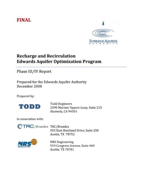
FINAL<br />
~<br />
~<br />
EoWARDSAQUIFER<br />
AUTHORITY<br />
Recharge and Recirculation<br />
<strong>Edwards</strong> <strong>Aquifer</strong> Optimization Program<br />
Phase III/IV Report<br />
Prepared for the <strong>Edwards</strong> <strong>Aquifer</strong> <strong>Authority</strong><br />
December 2008<br />
Prepared by:<br />
TODD<br />
Todd Engineers<br />
2490 Mariner Square Loop, Suite 215<br />
Alameda, CA 94501<br />
In association with:<br />
TRC· /Brandes TRC/Brandes<br />
505 East Huntland Drive, Suite 250<br />
Austin, TX 78752<br />
NRS Engineering<br />
919 Congress Avenue, Suite 460<br />
Austin, TX 78701
Table of Contents<br />
Executive Summary .................................................................................................................... ES1<br />
1. Introduction .................................................................................................................................... 1<br />
1.1. Background ............................................................................................................................................................. 1<br />
1.2. Purpose and Goals ............................................................................................................................................... 2<br />
1.2.1. Springflow Maintenance .......................................................................................................................... 3<br />
1.2.2. Sustainable Yield ......................................................................................................................................... 3<br />
1.3. Scope of Work ........................................................................................................................................................ 4<br />
1.4. Use of Numbers ..................................................................................................................................................... 5<br />
1.5. Acknowledgements ............................................................................................................................................. 5<br />
2. Concepts of Recirculation ....................................................................................................... 21<br />
2.1. Previous Investigations on R&R Strategies ........................................................................................... 2‐4<br />
2.1.1. Recharge Enhancement Studies ....................................................................................................... 2‐4<br />
2.1.2. Recirculation Studies ............................................................................................................................ 2‐7<br />
2.1.3. Todd Engineers R&R Phases I and II .............................................................................................. 2‐8<br />
2.2. EAA Rules ............................................................................................................................................................ 2‐9<br />
2.2.1. Critical Period Management (CPM) Rules .................................................................................... 2‐9<br />
2.2.2. <strong>Aquifer</strong> Recharge, Storage, and Recovery (ARSR) Rules ...................................................... 2‐10<br />
2.3. Application of the USGS MODFLOW Model ......................................................................................... 2‐11<br />
3. Baseline Scenario Development .......................................................................................... 31<br />
3.1. Modifications to EAA Model ......................................................................................................................... 3‐1<br />
3.1.1. Well File Modification ........................................................................................................................... 3‐1<br />
3.1.2. Initial Water Levels ................................................................................................................................ 3‐4<br />
3.1.3. Amended Critical Period Management Rules ............................................................................. 3‐4<br />
3.1.4. Resolution of Dry Cells in the Model............................................................................................... 3‐6<br />
3.1.5. Representative Hydrologic Conditions .......................................................................................... 3‐7<br />
3.2. Results of Baseline Scenario ........................................................................................................................ 3‐9<br />
4. Preliminary Groundwater Model Runs ............................................................................. 41<br />
FINAL – R&R Phase III/IV Report<br />
Page i
4.1. Evaluation of Enhanced Recharge at Type 2 Sites .............................................................................. 4‐1<br />
4.1.1. Evaluation of One Time (Slug) Recharge at Type 2 Sites ....................................................... 4‐2<br />
4.1.2. Evaluation of Annual Recharge at Type 2 Sites .......................................................................... 4‐6<br />
4.2. Evaluation of Minimum Springflow .......................................................................................................... 4‐9<br />
4.2.1. Minimum Springflow During Dry Conditions ........................................................................... 4‐10<br />
4.2.2. Minimum Springflow During Average Conditions .................................................................. 4‐11<br />
5. Source Water Availability ...................................................................................................... 51<br />
5.1. Surface Water .................................................................................................................................................... 5‐1<br />
5.1.1. Application and Modifications of Water Availability Models ............................................... 5‐4<br />
5.1.2. GSA Basin R&R Source Water .......................................................................................................... 5‐11<br />
5.1.3. Nueces Basin R&R Source Water ................................................................................................... 5‐15<br />
5.2. Unused <strong>Edwards</strong> <strong>Aquifer</strong> Permits ........................................................................................................... 5‐17<br />
5.3. Excess Springflow from Recirculation ................................................................................................... 5‐21<br />
6. Evaluation of Potential R& R Components ....................................................................... 61<br />
6.1. Description of Components .......................................................................................................................... 6‐1<br />
6.1.1. Type 2 Recharge Sites ........................................................................................................................... 6‐4<br />
6.1.2. Guadalupe River Diversions ............................................................................................................... 6‐5<br />
6.1.3. Recirculation of Excess Springflow ................................................................................................. 6‐5<br />
6.1.4. Pumping of Unused Withdrawal Rights ........................................................................................ 6‐6<br />
6.1.5. Selection of A Type 1 Recharge Structure .................................................................................... 6‐7<br />
6.2. Application of Source Water Data ............................................................................................................. 6‐8<br />
6.2.1. Unappropriated and Marketable Estimates ................................................................................ 6‐8<br />
6.2.2. Unused Withdrawal Permits .............................................................................................................. 6‐9<br />
6.3. Sizing of Recharge Structures and Pipelines ......................................................................................... 6‐9<br />
6.3.1. Sizing of Recharge Structures .......................................................................................................... 6‐10<br />
6.3.2. Sizing of Pipelines ................................................................................................................................. 6‐12<br />
6.4. Component Modeling Results ................................................................................................................... 6‐13<br />
6.4.1. Enhanced Recharge at Type 2 R&R Sites .................................................................................... 6‐13<br />
6.4.2. Enhanced Recharge with Guadalupe (and other) River Diversions ................................ 6‐20<br />
6.4.3. Recirculation of Excess Springflow ............................................................................................... 6‐24<br />
6.4.4. Enhanced Recharge using Groundwater from Unused Permits........................................ 6‐26<br />
6.4.5. Enhanced Recharge with Type 1 Structures ............................................................................. 6‐27<br />
FINAL – R&R Phase III/IV Report<br />
Page ii
6.5. Component Evaluations Summary and Costs ..................................................................................... 6‐29<br />
6.5.1. Component Yield ................................................................................................................................... 6‐31<br />
6.5.2. Component Costs .................................................................................................................................. 6‐31<br />
6.5.3. Combining Components into Scenarios ...................................................................................... 6‐32<br />
7. Recharge and Recirculation Scenarios .............................................................................. 71<br />
7.1. Scenario 1 ............................................................................................................................................................ 7‐2<br />
7.1.1. Development of Recovery Factors ................................................................................................... 7‐4<br />
7.1.2. Scenario 1a (without Enhanced Pumping) .................................................................................. 7‐6<br />
7.1.3. Scenario 1b (with Enhanced Pumping) ......................................................................................... 7‐7<br />
7.1.4. Results of Scenario 1b ........................................................................................................................... 7‐7<br />
7.2. Scenario 2 ............................................................................................................................................................ 7‐8<br />
7.2.1. Description ................................................................................................................................................ 7‐9<br />
7.2.2. Results of Scenario 2 ............................................................................................................................. 7‐9<br />
7.3. Scenario 3 .......................................................................................................................................................... 7‐10<br />
7.3.1. Description .............................................................................................................................................. 7‐10<br />
7.3.2. Results of Scenario 3 ........................................................................................................................... 7‐11<br />
7.4. Scenario 4 .......................................................................................................................................................... 7‐13<br />
7.4.1. Description .............................................................................................................................................. 7‐13<br />
7.4.2. Results of Scenario 4 ........................................................................................................................... 7‐14<br />
7.5. Scenario 5 .......................................................................................................................................................... 7‐15<br />
7.5.1. Description .............................................................................................................................................. 7‐15<br />
7.5.2. Results of Scenario 5 ........................................................................................................................... 7‐15<br />
7.6. Scenario No. 6 .................................................................................................................................................. 7‐17<br />
7.6.1. Description .............................................................................................................................................. 7‐17<br />
7.6.2. Results of Scenario 6 ........................................................................................................................... 7‐18<br />
7.7. Scenario No. 7 .................................................................................................................................................. 7‐19<br />
7.7.1. Description .............................................................................................................................................. 7‐19<br />
7.7.2. Results of Scenario 7 ........................................................................................................................... 7‐20<br />
7.8. Scenario Summary ......................................................................................................................................... 7‐21<br />
7.9. Facilities Costs ................................................................................................................................................. 7‐24<br />
7.10. Drought Yield .............................................................................................................................................. 7‐25<br />
7.11. Optimizing Considerations .................................................................................................................... 7‐28<br />
FINAL – R&R Phase III/IV Report<br />
Page iii
8. Conclusions and Recommendations ................................................................................... 81<br />
8.1. Conclusions ......................................................................................................................................................... 8‐1<br />
8.2. Recommendations and Limitations .......................................................................................................... 8‐4<br />
9. References ................................................................................................................................... 91<br />
10. Definition of Terms............................................................................................................. 101<br />
List of Tables<br />
Table 2‐1: Recommended Recharge Enhancement Program for the Nueces River Basin ... 2‐5<br />
Table 2‐2: Recommended Recharge Enhancement Program for the Guadalupe‐San Antonio<br />
(GSA) River Basin ................................................................................................................................................. 2‐6<br />
Table 2‐3. EAA Critical Period Management (CPM) Rules ............................................................... 2‐10<br />
Table 3‐1: Distribution of Annual Pumping on a Monthly Basis by Water Use ......................... 3‐3<br />
Table 3‐2: Withdrawal Reductions under CPM Rules As Amended by S.B. 3 ........................... 3‐5<br />
Table 3‐3: Representative Hydrologic Conditions ................................................................................. 3‐8<br />
Table 4‐1: Results of Slug Recharge 1947‐1973 ..................................................................................... 4‐3<br />
Table 4‐2: Results of Slug Recharge 1974‐2000 ..................................................................................... 4‐3<br />
Table 4‐3: <strong>Aquifer</strong> Retention Time for 1947 Slug Recharge .............................................................. 4‐5<br />
Table 4‐4: <strong>Aquifer</strong> Retention Time for 1974 Slug Recharge .............................................................. 4‐5<br />
Table 4‐5. Results of Enhanced Annual Recharge 1947‐1973 .......................................................... 4‐6<br />
Table 4‐6. Results of Enhanced Annual Recharge 25,000 AFY 1974‐2000................................. 4‐7<br />
Table 4‐7. Results of 25,000 AFY Enhanced Recharge as Percent Applied (1946‐1973) ..... 4‐8<br />
Table 4‐8. Results of 25,000 AFY Enhanced Recharge as Percent Applied (1974‐2000) ..... 4‐8<br />
Table 4‐9: <strong>Aquifer</strong> Retention Time for 25,000 AFY Recharge 1947‐1973 ................................. 4‐9<br />
Table 4‐10: <strong>Aquifer</strong> Retention Time for 25,000 AFY Recharge 1974‐2000 .............................. 4‐9<br />
Table 4‐11. Annual Enhanced Recharge to Maintain Comal Springs Flow for Dry and<br />
Average Conditions ........................................................................................................................................... 4‐10<br />
Table 5‐1: Summary of Regressions of Unappropriated Water with Gaged Flow ................ 5‐11<br />
Table 5‐2: GSA WAM Control Point Assignments for R&R Sites in the GSA Basin ................ 5‐12<br />
Table 5‐3: Summary of Unappropriated Water for Potential R&R Sites in the GSA Basin (AF)<br />
................................................................................................................................................................................... 5‐13<br />
Table 5‐4: Summary of Marketable Water for Potential R&R Sites in the GSA Basin (AF) 5‐14<br />
Table 5‐5: Nueces WAM Control Point Assignments for R&R Sites in the Nueces Basin ... 5‐15<br />
Table 5‐6: Summary of Unappropriated Water for Potential R&R Sites in the Nueces Basin<br />
(AF) .......................................................................................................................................................................... 5‐16<br />
FINAL – R&R Phase III/IV Report<br />
Page iv
Table 5‐7: Summary of Marketable Water for Potential R&R Sites in the Nueces Basin (AF)<br />
................................................................................................................................................................................... 5‐17<br />
Table 5‐8: Average Amounts of Unused Pumping Permits by County and Water Use ....... 5‐18<br />
Table 6‐1: List of Potential R&R Components .......................................................................................... 6‐2<br />
Table 6‐2: Comparison of Source Water for the Phase III Study to Previous Studies ......... 6‐10<br />
Table 6‐3: Yield as Percent of Enhanced Recharge at Type 2 Recharge Sites ........................ 6‐16<br />
Table 6‐4: Yield as Percent of Enhanced Recharge at Type 2 Sites without the Lower Blanco<br />
Recharge Site ....................................................................................................................................................... 6‐17<br />
Table 6‐5: Yield from Type 2 Enhanced Recharge Program with and without the Lower<br />
Blanco Recharge Site ........................................................................................................................................ 6‐17<br />
Table 6‐6: Average Enhanced Recharge Available at Type 2 Sites .............................................. 6‐18<br />
Table 6‐7. Percent Difference between HDR Recharge and WAM‐Generated Recharge at<br />
Type 2 Sites .......................................................................................................................................................... 6‐19<br />
Table 6‐8: Percent Difference between HDR Recharge and WAM‐Generated Recharge at<br />
Type 2 Sites without Lower Blanco ........................................................................................................... 6‐20<br />
Table 6‐9: Comparison of Yield between Lower Verde/Lower Hondo and San Geronimo<br />
Recharge Sites for Comfort/Medina Source Water ............................................................................ 6‐22<br />
Table 6‐10. Comparison of Benefits between Cibolo Recharge Site and San Geronimo<br />
Recharge Site for Dunlap Source Water .................................................................................................. 6‐23<br />
Table 6‐11. Comparison of Benefits between Canyon Lake and Lake Dunlap Diversion Sites<br />
to Cibolo Type 2 Recharge Site .................................................................................................................... 6‐24<br />
Table 6‐12: Yield for Enhanced Recharge and Excess Springflow Recirculation and the<br />
Percent Difference ............................................................................................................................................. 6‐25<br />
Table 6‐13: Total Yield from Unused Permits ....................................................................................... 6‐27<br />
Table 6‐14: Comparison of Yield from Recharge in a Type 1 Recharge Structure (timed<br />
release) and a Type 2 Recharge Structure (recharged as available) .......................................... 6‐28<br />
Table 6‐15: Comal Springs Comparison of Type 1 and Type 2 Recharge ................................. 6‐28<br />
Table 6‐16: R&R Components ‐ Yield and Costs ................................................................................. 6‐30<br />
Table 7‐1: Summary of R&R Scenarios ....................................................................................................... 7‐2<br />
Table 7‐2: Recovery Factors – Percent of Recoverable Recharge at Recharge Sites .............. 7‐5<br />
Table 7‐3: Scenario 1a without Enhanced Pumping ............................................................................. 7‐6<br />
Table 7‐4: Scenario 1a without Enhanced Pumping as Percent of Enhanced Recharge ....... 7‐6<br />
Table 7‐5: Yield of Scenario 1b ....................................................................................................................... 7‐7<br />
Table 7‐6: Yield of Scenario 1b as a Percent of Enhanced Recharge ............................................. 7‐8<br />
Table 7‐7: Yield of Scenario 2 .......................................................................................................................... 7‐9<br />
Table 7‐8: Yield of Scenario 2 as a Percent of Enhanced Recharge ............................................. 7‐10<br />
Table 7‐9. Yield of Scenario 3 with Enhanced Pumping and Recirculation Pumping ......... 7‐12<br />
Table 7‐10. Yield of Scenario 3 as a Percent of Enhanced Recharge ........................................... 7‐12<br />
Table 7‐11: Yield of Scenario 4 .................................................................................................................... 7‐14<br />
FINAL – R&R Phase III/IV Report<br />
Page v
Table 7‐12: Yield of Scenario 4 as a Percent of Enhanced Recharge .......................................... 7‐14<br />
Table 7‐13. Annual Average Yield of Scenario 5 .................................................................................. 7‐16<br />
Table 7‐14. Yield of Scenario 5 as a Percent of Enhanced Recharge ........................................... 7‐16<br />
Table 7‐15: Yield of Scenario 6 .................................................................................................................... 7‐18<br />
Table 7‐16: Scenario 6 as a Percent of Enhanced Recharge ........................................................... 7‐18<br />
Table 7‐17: Yield of Scenario 7 .................................................................................................................... 7‐20<br />
Table 7‐18: Yield of Scenario 7 as a Percent of Enhanced Recharge .......................................... 7‐21<br />
Table 7‐19: Comparison of R&R Scenarios ............................................................................................ 7‐22<br />
Table 7‐20. Annualized Cost for Scenarios (in millions of dollars) ............................................. 7‐25<br />
Table 7‐21. Drought Yield .............................................................................................................................. 7‐27<br />
List of Illustrations<br />
2‐1: Example Bar Graph Illustrating the Fate of Recharged Water ......................................................... 2‐2<br />
2‐2: Types of Recharge Structures ........................................................................................................................ 2‐3<br />
3‐1: Original Pumping from the MODFLOW Model ....................................................................................... 3‐2<br />
3‐2: Monthly Distribution of Pumping by Water Use ................................................................................... 3‐3<br />
3‐3: Comal Springflow under Original and Baseline Conditions .............................................................. 3‐10<br />
5‐1: Unused Withdrawal Permits .......................................................................................................................... 5‐19<br />
5‐2: Precipitation at Selected Stations across the <strong>Edwards</strong> <strong>Aquifer</strong> ...................................................... 5‐20<br />
List of Figures (following text)<br />
1‐1. Study Area with R&R Recharge Sites<br />
3‐1. Pumping Totals under CPM Rules<br />
3‐2. Representative Hydrologic Cycles<br />
3‐3. Baseline Scenario – Comal and San Marcos Springs<br />
3‐4. Baseline Scenario – Water Levels in J‐17 and J‐27<br />
4‐1. Results of Slug Recharge Analysis<br />
4‐2. Retention Time of Slug Recharge<br />
4‐3. Results of 25,000 AFY Annual Recharge<br />
4‐4. Retention Time of Annual Recharge<br />
4‐5. Enhanced Recharge Required for Minimum Springflow of 40 cfs for Dry Conditions<br />
4‐6. Enhanced Recharge Required for Minimum Springflow of 150 cfs for Dry Conditions<br />
4‐7. Enhanced Recharge Required for Minimum Springflow of 150 cfs for Average Conditions<br />
5‐1. Source Water Sites<br />
6‐1. R&R Components<br />
6‐2. Histograms of the Unappropriated Water at Dunlap and Canyon Sites<br />
6‐3. Histograms of the Unappropriated Water at Comfort and Medina River<br />
FINAL – R&R Phase III/IV Report<br />
Page vi
6‐4. Unappropriated and Marketable Water for Type 2 R&R Sites<br />
6‐5. Unappropriated Water for the Central Type 2 Sites (Lower Frio to Lower Verde)<br />
6‐6. Total Yield from Type 2 Enhanced Recharge (Maximum Available Source Water)<br />
6‐7. Total Yield from Type 2 Enhanced Recharge (Unappropriated Water)<br />
6‐8. Recharge Remaining in the <strong>Aquifer</strong> over Time, Indian Creek<br />
6‐9. Recharge Remaining in the <strong>Aquifer</strong> over Time, Lower Frio<br />
6‐10. Recharge Remaining in the <strong>Aquifer</strong> over Time, Lower Sabinal<br />
6‐11. Recharge Remaining in the <strong>Aquifer</strong> over Time, Lower Hondo<br />
6‐12. Recharge Remaining in the <strong>Aquifer</strong> over Time, Lower Verde<br />
6‐13. Recharge Remaining in the <strong>Aquifer</strong> over Time, San Geronimo<br />
6‐14. Recharge Remaining in the <strong>Aquifer</strong> over Time, Cibolo Dam<br />
6‐15. Recharge Remaining in the <strong>Aquifer</strong> over Time, Lower Blanco<br />
6‐16. Total Yield Enhanced Recharge at All Type 2 Sites<br />
6‐17. Total Yield Enhanced Recharge Type 2 Sites (Excluding Lower Blanco)<br />
6‐18. Total Yield of Type 2 Enhanced Recharge with HDR Source Water Estimates<br />
6‐19. Total Yield of Type 2 (excluding Lower Blanco) Enhanced Recharge with HDR Source Water<br />
Estimates<br />
6‐20. Total Source Water for Enhanced Recharge at Type 2 Sites with Excess Springflow<br />
6‐21. Yield of Excess Springflow Recirculation<br />
7‐1. Enhanced Recharge, Scenarios 1, 2, and 5<br />
7‐2. Recovery Factors for Various Recharge Sites<br />
7‐3. Results of Scenario 1a without Enhanced Pumping<br />
7‐4. Results of Scenario 1b with Enhanced Pumping<br />
7‐5. Results of Scenario 2<br />
7‐6. Enhanced Recharge for Scenarios 3 and 4<br />
7‐7. Scenario 3 Enhanced Pumping and Recirculation Pumping<br />
7‐8. Results of Scenario 3 with Enhanced/Recirculation Pumping<br />
7‐9. Scenario 4 Enhanced Pumping and Recirculation<br />
7‐10. Results of Scenario 4<br />
7‐11. Results of Scenario 5<br />
7‐12. Range of Possible Excess Springflow for Recirculation<br />
7‐13. Enhanced Recharge for Scenario 6<br />
7‐14. Results of Scenario 6<br />
7‐15. Enhanced Recharge for Scenario 7<br />
7‐16. Results of Scenario 7<br />
7‐17. Scenario 7 Enhanced Pumping for Recharge Recovery<br />
List of Appendices<br />
A. Recharge and Recirculation Phase III and Phase IV Scope of Work<br />
B. Results of Surface Water Modeling<br />
C. Conceptual Engineering and Cost Estimates<br />
FINAL – R&R Phase III/IV Report<br />
Page vii
EXECUTIVE SUMMARY<br />
For more than three decades, the <strong>Edwards</strong> <strong>Aquifer</strong> <strong>Authority</strong> (EAA), its predecessor, and<br />
others have evaluated groundwater management strategies to more productively use the<br />
shared resource of the <strong>Edwards</strong> <strong>Aquifer</strong>. These strategies have involved, among others,<br />
enhancing natural recharge and recirculating groundwater discharge back into the aquifer<br />
system. This study builds on previous investigations and re‐evaluates recharge and<br />
recirculation (R&R) strategies incorporating:<br />
• analysis with an improved computer flow model,<br />
• updated estimates of available source water, and<br />
• recently‐adopted EAA rules for various aspects of aquifer management.<br />
The study also evaluates combinations of strategies and provides preliminary costs for<br />
facilities to support implementation of an R&R program. Benefits to the region are<br />
evaluated in terms of increased water supply and maintaining minimum springflow at key<br />
springs including Comal and San Marcos springs.<br />
This report is part of Phase IV of various R&R tasks performed by Todd Engineers for EAA.<br />
It summarizes previously‐reported work on Phases I and II and describes new analyses<br />
conducted in Phase III. It is herein referred to as the Phase III/IV report. Our scope of<br />
services for this project is provided as Appendix A.<br />
The report is organized into 10 chapters, each of which summarizes a specific component<br />
of the work. This Executive Summary is organized around these chapter headings and<br />
briefly describes the results. A summary of the report is provided below:<br />
• Chapter 1 introduces the project and provides goals, objectives, and a scope of work<br />
• Chapter 2 describes R&R concepts and provides a framework for the analysis<br />
• Chapter 3 defines baseline conditions against which R&R strategies are evaluated<br />
• Chapter 4 describes the relative performance of various recharge sites for water<br />
supply and maintaining Comal Springs above minimum targets for flow.<br />
• Chapter 5 evaluates the availability of various source waters for enhanced recharge<br />
• Chapter 6 describes various R&R components, evaluated separately, for possible<br />
inclusion in a regional R&R program.<br />
• Chapter 7 combines R&R components into regional R&R scenarios, maximizing the<br />
amount of water available for recharge<br />
• Chapter 8 provides conclusions and recommendations<br />
• Chapter 9 lists references cited and/or reviewed for this study<br />
• Chapter 10 provides a glossary that defines technical terms used in this report<br />
Recharge sites evaluated in this study are shown on Figure ES‐1.<br />
FINAL – R&R Phase III/IV Report – EXECUTIVE SUMMARY<br />
Page ES‐1
N<br />
RECHARGE ZONE<br />
Kinney<br />
Indian<br />
Creek<br />
J27<br />
Lower<br />
Sabinal<br />
Lower<br />
Frio<br />
Uvalde<br />
Leona<br />
Seco<br />
Creek<br />
Lower<br />
Hondo<br />
Lower<br />
Verde<br />
CONFINED ZONE<br />
Medina<br />
San<br />
Geronimo<br />
Bexar<br />
Comal<br />
Cibolo<br />
Hays<br />
J17<br />
San Antonio<br />
San Pedro<br />
Lower<br />
Blanco<br />
Caldwell<br />
San<br />
Marcos<br />
Comal<br />
Guadalupe<br />
0<br />
75<br />
Scale in Miles<br />
LEGEND<br />
Recharge Site<br />
Spring<br />
Monitoring Well<br />
County Line<br />
Stream/River<br />
Zavala<br />
Frio<br />
Atacosa<br />
October 2008<br />
TODD ENGINEERS<br />
Alameda, California<br />
Figure ES-1<br />
Study Area With<br />
R&R Recharge Sites
INTRODUCTION (CHAPTER 1)<br />
Chapter 1 introduces the project in the Background section. The goals of springflow<br />
maintenance and sustainable yield are described, and the scope of work is summarized.<br />
CONCEPTS OF RECIRCULATION (CHAPTER 2)<br />
Natural infiltration of rainfall and streamflow across the recharge zone of the aquifer<br />
provides the source for groundwater that is pumped for water supply and discharged at<br />
springs. Increasing the amount of infiltration (enhanced recharge) by capturing storm<br />
flows or importing water to the recharge zone has been recognized for decades as a way to<br />
increase water supply and springflow. As the enhanced recharge increases groundwater<br />
storage, EAA rules allow for an applicant to recover the stored water for use. If the stored<br />
water is not needed at certain times, it may be beneficial to return that water to the<br />
recharge zone, a concept referred to as recirculation (see Chapter 10 definitions of terms).<br />
To analyze the fate of enhanced recharge as it moves through the aquifer system, this<br />
report uses bar graphs indicating locations and quantities of the recharged water at certain<br />
times. For example, at some period of time after water has been recharged into the aquifer<br />
system, the enhanced recharge is either still in the aquifer system (contributing to<br />
groundwater storage) or has been discharged from wells (pumping) or springs (Comal<br />
Springs or other springs). A bar graph illustrating this type of analysis is provided below:<br />
Illustration ES1: Example Bar Graph Illustrating the Fate of Recharged Water<br />
Remaining in <strong>Aquifer</strong> (groundwater storage)<br />
Pumping (discharge from wells)<br />
Other Springs (spring discharge other than Comal Springs)<br />
Comal (discharge from Comal Springs)<br />
Enhanced recharge requires some type of engineered structure to contain the source water<br />
to allow for infiltration. This report evaluates previously‐identified sites for recharge<br />
referred to as a Type 1 or Type 2 site. A Type 1 site is located upstream of the recharge area<br />
and holds water for later release to the recharge zone. A Type 2 site is located on the<br />
recharge zone and captures water for direct infiltration. A schematic diagram from<br />
previous recharge investigations is provided below illustrating the two types of structures.<br />
FINAL – R&R Phase III/IV Report – EXECUTIVE SUMMARY<br />
Page ES‐3
Illustration ES2: Types of Enhanced Recharge Structures<br />
After HDR, et al., 1991<br />
BASELINE CONDITIONS (CHAPTER 3)<br />
For this study, a baseline scenario was developed using the EAA model (covering<br />
hydrologic conditions for 1946‐2000) and incorporating the recently‐amended pumping<br />
cap and CPM rules for the model period of record. Pumping for each aquifer pool and CPM<br />
reductions are summarized on Table ES‐1.<br />
Table ES1: Withdrawal Reductions under Current CPM Rules for Baseline Scenario<br />
Critical<br />
Period<br />
Stage<br />
San Antonio Pool<br />
Pumping<br />
(AFY)<br />
Withdrawal<br />
Reduction<br />
(percent)<br />
Pumping<br />
(AFY)<br />
Uvalde Pool<br />
Withdrawal<br />
Reduction<br />
(percent)<br />
Total<br />
Pumping<br />
(AFY)<br />
448,095 123,905 572,000<br />
I 358,476 20% 123,905 NA 482,381<br />
II 313,666 30% 117,710 5% 431,376<br />
III 291,262 35% 99,124 20% 390,386<br />
IV 268,857 40% 80,538 35% 349,395<br />
Results of the baseline scenario are shown for springflow at Comal Springs and San Marcos<br />
Springs (Figure ES‐2) and water levels in index wells J‐17 and J‐27 (Figure ES‐3).<br />
FINAL – R&R Phase III/IV Report – EXECUTIVE SUMMARY<br />
Page ES‐4
500<br />
Comal Springs - San Antonio Pool<br />
450<br />
400<br />
350<br />
Springflow (cfs)<br />
300<br />
250<br />
200<br />
150<br />
100<br />
Critical<br />
Period Stage:<br />
I<br />
II<br />
III<br />
50<br />
IV<br />
0<br />
500<br />
1946 1951 1956 1961 1966 1971 1976 1981 1986 1991 1996<br />
Calendar Year<br />
San Marcos Springs - San Antonio Pool<br />
450<br />
400<br />
350<br />
Springflow (cfs)<br />
300<br />
250<br />
200<br />
150<br />
100<br />
50<br />
Critical<br />
Period Stage:<br />
I<br />
II<br />
0<br />
1946 1951 1956 1961 1966 1971 1976 1981 1986 1991 1996<br />
Calendar Year<br />
October 2008<br />
TODD ENGINEERS<br />
Alameda, California<br />
Figure ES-2<br />
Baseline Scenario<br />
Comal and<br />
San Marcos Springs
700<br />
Index Well J-17 - San Antonio Pool<br />
Groundwater Elevation (ft msl) Groundwater Elevation (ft msl)<br />
675<br />
650<br />
625<br />
600<br />
J-17<br />
575<br />
550<br />
1946 1956 1966 1976 1986 1996<br />
Calendar Year<br />
950<br />
925<br />
900<br />
875<br />
850<br />
825<br />
800<br />
Index Well J-27 - Uvalde Pool<br />
Critical<br />
Period Stage:<br />
I<br />
II<br />
III<br />
IV<br />
Critical<br />
Period Stage:<br />
II III<br />
IV<br />
775<br />
J-27<br />
750<br />
1946 1956 1966 1976 1986 1996<br />
Calendar Year<br />
October 2008<br />
TODD ENGINEERS<br />
Alameda, California<br />
Figure ES-3<br />
Baseline Scenario<br />
Water Levels in<br />
J-17 and J-27
As shown on the figures, both pools are in some stage of critical period for most of the<br />
baseline scenario. For the San Antonio Pool, Stage IV reductions are in effect for most of the<br />
drought of record from about 1951 through 1956. Comal Springs is the primary trigger for<br />
most of the CPM stages. Critical flows are San Marcos Springs are typically reached after the<br />
CPM thresholds have already been triggered at Comal Springs. For the Uvalde Pool, Stage IV<br />
is in effect through the drought and into the 1970s.<br />
Springflow output from the model was also used to develop a new baseline scenario for the<br />
surface water model. The baseline scenario conditions and results were provided to EAA in<br />
August 2007 for approval prior to proceeding with this study.<br />
PRELIMINARY GROUNDWATER MODEL RUNS (CHAPTER 4)<br />
Baseline conditions were applied to a series of preliminary groundwater model runs to<br />
evaluate the aquifer response to enhanced recharge for different locations, volumes, and<br />
timing. Recharge sites shown on Figure ES‐1 were evaluated. Simulations of both one‐time<br />
(slug) recharge and continuous annual recharge (applied seasonally each year) were<br />
evaluated.<br />
Results indicated that recharge at almost all of the Type 2 sites immediately increased<br />
pumping over baseline due to a lessening of critical period stages caused by rising water<br />
levels and spring discharge. Centrally‐located Type 2 sites contributed more to pumping<br />
than sites on the eastern and western ends of the basin. There, enhanced recharge<br />
contributed more to springflow, especially during wet conditions. A large proportion of<br />
enhanced recharge at the Lower Blanco site was discharged at San Marcos Springs with no<br />
benefits to pumping and relatively small benefits to Comal Springs. Recharge at the Cibolo<br />
site also had benefits to San Marcos Springs. Recharge at the Indian Creek site contributed<br />
to Leona Springs during wet conditions, but showed contributions to pumping and aquifer<br />
storage during dry conditions. The fate of enhanced recharge was similar for a particular<br />
site whether recharge was applied as a one‐time slug or continuously.<br />
Analysis of aquifer retention time indicated that enhanced recharge at the central and<br />
western recharge sites remained in the aquifer longer than recharge at eastern sites. This<br />
analysis identified sites where long‐term storage was best achievable. Analyses under<br />
baseline conditions indicated that 80 percent of the enhanced recharge water was still in<br />
the aquifer after about one year at most western and central sites. The analysis indicates<br />
that these times could be used to develop recovery factors for EAA recovery permits.<br />
Although groundwater modeling indicated that some amount of enhanced recharge<br />
persisted for years in the aquifer, analyses beyond a few years were judged as more<br />
uncertain.<br />
Recharge sites were also evaluated for their specific efficiency at maintaining springflow at<br />
Comal Springs above critical levels of 40 cubic feet per second (cfs) and 150 cfs. Results are<br />
summarized in Table ES‐2.<br />
FINAL – R&R Phase III/IV Report – EXECUTIVE SUMMARY<br />
Page ES‐7
Table ES2. Annual Enhanced Recharge (in AFY) to Maintain Comal Springs Flow for<br />
Dry and Average Conditions<br />
Type 2 Recharge Site<br />
Dry Conditions (19471956)<br />
(AFY)<br />
Average Conditions (19761983)<br />
(AFY)<br />
40 cfs 150 cfs 40 cfs 150 cfs<br />
Indian Creek 575,000 1,850,000 ‐ 150,000<br />
Lower Frio 400,000 750,000 ‐ 80,000<br />
Lower Sabinal 150,000 325,000 ‐ 33,000<br />
Seco Creek 155,000 315,000 ‐ 35,000<br />
Lower Hondo 160,000 325,000 ‐ 35,000<br />
Lower Verde 165,000 350,000 ‐ 40,000<br />
San Geronimo 117,000 260,000 ‐ 25,000<br />
Cibolo 160,000 340,000 ‐ 27,000<br />
Lower Blanco 5,000,000 > 10,000,000 ‐ 300,000<br />
Table ES‐2 summarizes the enhanced recharge required to maintain Comal Springs at 40<br />
cfs and 150 cfs during both dry and average hydrologic conditions. For dry conditions,<br />
maintaining springflow above 150 cfs takes about twice the amount for 40 cfs. In addition,<br />
an order of magnitude more water is needed for maintenance above 150 cfs during dry<br />
conditions than during average conditions. Under average conditions, Comal Springs flow is<br />
always above 40 cfs and does not require enhanced recharge for maintenance. As shown on<br />
the table, the San Geronimo site appears to be the most efficient at maintaining minimum<br />
springflow at Comal Springs, requiring about 117,000 AFY of enhanced recharge for<br />
springflow maintenance at 40 cfs and about twice that amount to keep springflow above<br />
150 cfs during the drought of record. It is currently unknown whether the required amount<br />
of enhanced recharge could be achieved at the site and further study on site‐specific<br />
infiltration rates is recommended. Although not indicated on the table, the Cibolo site is the<br />
most efficient for supplying both Comal Springs and San Marcos Springs.<br />
Enhanced recharge at the western sites (Indian Creek and Lower Frio) is not efficient for<br />
springflow maintenance and requires much larger quantities of enhanced recharge than<br />
other sites. The Lower Blanco is the most inefficient for Comal Springs flow maintenance,<br />
given its downgradient location. Quantities of enhanced recharge required for these target<br />
levels could not likely be recharged there due to physical limitations. Further, Lower<br />
Blanco does not appear to be capable of maintaining springflow above 150 cfs during dry<br />
conditions.<br />
FINAL – R&R Phase III/IV Report – EXECUTIVE SUMMARY<br />
Page ES‐8
SOURCE WATER AVAILABILITY (CHAPTER 5)<br />
Potential sources of water evaluated for enhanced recharge include the following:<br />
• Un‐captured surface water across the recharge zone at the Type 2 sites<br />
• Surface water at potential diversion sites along the Guadalupe River<br />
• Unused EAA withdrawal permits<br />
• Unrecovered groundwater and surface water that results from enhanced recharge<br />
(recirculation)<br />
The potentially available surface water at the Type 2 sites and along the Guadalupe River<br />
was determined using Water Availability Models (WAM) developed by the TCEQ. The<br />
WAMs were modified to be consistent with baseline conditions by incorporating<br />
springflow output from the groundwater model into the WAM. Using regression analyses,<br />
the WAM time periods were extended to 2000 to coincide with the groundwater model.<br />
The WAMs were used to generate unappropriated and marketable water at each of the<br />
designated R&R sites in the scope of services (Appendix A). For unappropriated water, a<br />
particular WAM simulation referred to as “Run 3” was conducted. This run accounts for all<br />
existing water rights in a particular basin with these rights exercised at their fully<br />
authorized diversion and storage amounts, typically without any return flows associated<br />
with the diversions. Following acquisition of proper water right permits from the TCEQ,<br />
these are the total quantities of streamflow that potentially could be available for recharge,<br />
less any diversion restrictions of streamflow use determined in the permitting process.<br />
Results of this analysis are summarized in Chapter 5 and presented in Appendix B. One<br />
conclusion from the unappropriated analysis was that significantly less water was available<br />
for recharge at the western Type 2 recharge sites (Nueces Basin) than had been used in<br />
previous evaluations by HDR for the Region L Water Plan. For the model period (1947‐<br />
2000), unappropriated water is only available during 17 years and 8 years at the Lower<br />
Sabinal and Lower Frio Type 2 recharge sites, respectively, and amounts are generally very<br />
small. This appears to be primarily the result of fully honoring the storage rights in the<br />
Choke Canyon Reservoir/Lake Corpus Christi system in the WAM analysis. Previous studies<br />
had assumed that impacts on the water supply and estuarine inflows would be mitigated<br />
with alternative water sources and/or financial mechanisms.<br />
For this analysis, marketable water is assumed to be that portion of streamflow that is<br />
appropriated by existing water rights, but not fully utilized under current conditions. For<br />
this project, the idea is that such rights might be acquired (purchased or leased) from one<br />
or more water right owners during a period of time when owners do not need the water.<br />
For the development of marketable amounts of water, a simulation of the WAM referred to<br />
as “Run 8” was used. This analysis accounts for all existing water rights, but only to the<br />
extent the right has been exercised during the last 10 years of the model run (late 1980s to<br />
late 1990s). In general, the difference between the amount of rights used (Run 8) and the<br />
FINAL – R&R Phase III/IV Report – EXECUTIVE SUMMARY<br />
Page ES‐9
amount of rights appropriated (Run 3) was viewed as marketable water. Additional<br />
adjustments were made to the WAMs to allow comparison of the output of these runs.<br />
Details of the methodology and results are provided in Chapter 5. Complete results for<br />
Marketable and Unappropriated water are presented in Appendix B.<br />
In addition to the surface water analysis associated with the WAM, two additional water<br />
sources were evaluated including unused withdrawal permits and excess springflow due to<br />
enhanced recharge. The unused withdrawal permits represent EAA permit holders that do<br />
not pump their full allocation of groundwater each year. These unused permits account for<br />
a significant amount of water, especially during wet years when groundwater pumping is<br />
generally less. These amounts could potentially be leased or purchased as a source of<br />
enhanced recharge when groundwater is not needed for beneficial use. At first, the concept<br />
of pumping groundwater already in storage back to the recharge zone may not seem<br />
beneficial. However, because of the geologic complexities within the aquifer system, the<br />
strategy allows for movement of water to certain recharge sites where specific goals of<br />
either long‐term storage or springflow maintenance can be obtained.<br />
EAA staff provided the amount of unused permits from 1999 to 2006 for the evaluation of<br />
potential recharge source water. Average amounts of permits by pool and permit type are<br />
shown on Table ES‐3. Actual annual amounts are shown on the graph following the table.<br />
Table ES3: Average Amounts of Unused Pumping Permits by County and Water Use<br />
Average Unused Permits 19992006<br />
Pool<br />
County Irrigation Muni/Ind.<br />
(AFY) (AFY)<br />
TOTAL (AFY)<br />
Uvalde Pool<br />
Uvalde 66,631 1,241 67,872<br />
San Antonio Pool<br />
Medina 54,478 2,840 57,318<br />
Bexar 25,717 22,044 47,761<br />
Comal 951 6,993 7,944<br />
Hays 867 4,243 5,110<br />
Subtotal 82,013 36,120 118,133<br />
TOTAL 148,644 37,361 186,005<br />
FINAL – R&R Phase III/IV Report – EXECUTIVE SUMMARY<br />
Page ES‐10
Illustration ES3: Unused Withdrawal Permits 1999 – 2006<br />
AFY<br />
200,000<br />
180,000<br />
160,000<br />
140,000<br />
120,000<br />
100,000<br />
80,000<br />
60,000<br />
40,000<br />
20,000<br />
0<br />
Uvalde Pool<br />
San Antonio Pool<br />
1999 2000 2001 2002 2003 2004 2005 2006<br />
Calendar Year<br />
For irrigation permits, a portion of the allocation may not be available for offsite use as<br />
would be required by R&R strategies. According to EAA permit rules, one‐half of an<br />
irrigation permit amount is tied to the parcel on which the irrigation permit is held (base<br />
permit) and generally cannot be pumped on other lands. To account for this base permit,<br />
unused irrigation permit amounts were adjusted downward by one‐fourth, assuming that<br />
one‐half of the permits represented the base portion of the permits. Applying this<br />
methodology, average annual amounts of unused permits of 51,215 AFY and 97,630 AFY<br />
were used for the Uvalde Pool and San Antonio Pool, respectively.<br />
R&R COMPONENTS (CHAPTER 6)<br />
To evaluate R&R strategies in a systematic manner, 29 components of recharge and<br />
recirculation were identified for analysis for both individual and combined analyses. This<br />
extra step allowed for the individual assessment of an R&R component’s impact on critical<br />
period rules, water levels, springflow, and aquifer storage. For the purposes of this analysis,<br />
a component designates a specific location (such as one Type 2 site) linked to available<br />
source water (i.e., unappropriated or marketable streamflow, a new groundwater source,<br />
or recirculated water), either at that location or piped from a nearby source. Preliminary<br />
costs were also developed for the components as summarized in Appendix C. Components<br />
are described in detail in Chapter 6. Components are shown conceptually on Figure ES‐4.<br />
Table ES‐4 provides a list of the components (abbreviated to reflect the model simulation<br />
name), results from the analyses, and preliminary annualized costs.<br />
FINAL – R&R Phase III/IV Report – EXECUTIVE SUMMARY<br />
Page ES‐11
N<br />
Hays<br />
0<br />
Scale in Miles<br />
75<br />
Comfort<br />
*<br />
Guadalupe<br />
River<br />
Comal<br />
Canyon<br />
*<br />
Lower<br />
Blanco<br />
FRS<br />
San<br />
Marcos<br />
Caldwell<br />
RECHARGE ZONE<br />
Indian<br />
Creek<br />
Dry Frio<br />
J27<br />
CONFINED ZONE<br />
Lower<br />
Frio<br />
Lower<br />
Sabinal<br />
Dry<br />
Frio<br />
Uvalde<br />
Wellfield<br />
Uvalde<br />
Leona<br />
Zavala<br />
Upper<br />
Seco<br />
Seco<br />
Creek<br />
Medina River<br />
Lower<br />
Hondo<br />
Lower<br />
Verde<br />
Frio<br />
Medina<br />
Lake<br />
Medina<br />
Wellfield<br />
Medina<br />
San<br />
Geronimo<br />
Bexar<br />
Cibolo<br />
J17<br />
San Antonio<br />
San Pedro<br />
Atacosa<br />
*<br />
Comal<br />
*<br />
*<br />
Dunlap<br />
Guadalupe<br />
LEGEND<br />
Recharge Site<br />
Spring<br />
Index Well<br />
County Line<br />
Stream/River<br />
Type I Recharge Site<br />
Component Pipeline<br />
Component Diversion Site<br />
Component Wellfield<br />
Note: R&R components shown on this map were<br />
analyzed in this study and do not collectively<br />
represent a recommended R&R program.<br />
Pipeline alignments and wellfields are schematic.<br />
October 2008<br />
TODD ENGINEERS<br />
Alameda, California<br />
Figure ES-4<br />
R&R<br />
Components
Table ES‐4: R&R Components ‐ Yield and Costs<br />
Component<br />
Recharge and Yield<br />
Average Conditions (1947-2000)<br />
Recharge and Yield<br />
Drought Conditions (1947-1956)<br />
Annual Costs<br />
Annual Benefits - Average Conditions<br />
(Cost per AF)<br />
ID<br />
Abbreviated Name for Model<br />
Simulation<br />
Total<br />
Recharge<br />
(AFY)<br />
Permit<br />
Pumping<br />
(AFY)<br />
Comal<br />
Springs<br />
(AFY)<br />
Remaining in<br />
<strong>Aquifer</strong><br />
(AFY)<br />
Drought<br />
Recharge<br />
(AFY)<br />
Permit<br />
Pumping<br />
(AFY)<br />
Comal<br />
Springs<br />
(AFY)<br />
Remaining in<br />
<strong>Aquifer</strong><br />
(AFY)<br />
Annual Cost 1<br />
($)<br />
Total<br />
Recharge<br />
($/AF)<br />
Permit Comal Springs<br />
Pumping ($/AF) ($/AF)<br />
Pumping +<br />
Comal<br />
($/AF)<br />
1 IC Type 2 Unappropriated 2 11,299 2,976 1,233 9,072 0 0 0 0 $ 56,832,284 $ 5,030 $ 19,095 $ 46,103 $ 13,503<br />
2 LF Type 2 Unappropriated 264 52 75 85 3 0 1 2 $ 5,443,880 $ 20,658 $ 104,798 $ 72,961 $ 43,014<br />
3 LS Type 2 Unappropriated 64 70 2 6 310 1 197 124 $ 1,600,456 $ 24,849 $ 22,748 $ 875,228 $ 22,172<br />
4 LH Type 2 Unappropriated 673 105 332 137 246 0 163 91 $ 1,580,141 $ 2,349 $ 15,051 $ 4,753 $ 3,612<br />
5 LV Type 2 Unappropriated 300 94 127 84 235 1 137 129 $ 1,692,932 $ 5,651 $ 17,915 $ 13,295 $ 7,632<br />
6 SG Type 2 Unappropriated 4,591 2,067 1,661 668 181 222 293 309 $ 979,708 $ 213 $ 474 $ 590 $ 263<br />
7 C Type 2 Unappropriated 24,020 3,587 10,292 4,137 3,767 769 2,165 1,581 $ 4,107,688 $ 171 $ 1,145 $ 399 $ 296<br />
8 LB Type 2 Unappropriated 80,829 442 2,514 2,297 10,965 378 293 5,502 $ 9,018,341 $ 112 $ 20,412 $ 3,588 $ 3,051<br />
9 IC Type 2 Maximum 24,083 8,897 4,776 24,529 2,147 55 108 1,755 $ 56,832,284 $ 2,360 $ 6,388 $ 11,899 $ 4,156<br />
10 LF Type 2 Maximum 9,820 2,987 1,995 4,934 4,421 1,491 714 2,373 $ 5,443,880 $ 554 $ 1,823 $ 2,728 $ 1,093<br />
11 LS Type 2 Maximum 3,224 1,882 1,618 1,254 683 81 409 228 $ 1,600,456 $ 496 $ 851 $ 989 $ 457<br />
12 LH Type 2 Maximum 2,997 1,677 1,784 1,246 480 4 348 204 $ 1,580,141 $ 527 $ 942 $ 886 $ 457<br />
13 LV Type 2 Maximum 1,120 594 691 644 330 0 233 196 $ 1,692,932 $ 1,512 $ 2,850 $ 2,450 $ 1,317<br />
14 SG Type 2 Maximum 4,807 4,260 3,436 1,423 322 223 413 355 $ 979,708 $ 204 $ 230 $ 285 $ 127<br />
15 C Type 2 Maximum 24,261 7,284 20,673 8,396 3,768 769 2,165 1,581 $ 4,107,688 $ 169 $ 564 $ 199 $ 147<br />
16 LB Type 2 Maximum 90,362 991 5,294 4,725 21,478 257 577 4,889 $ 9,018,341 $ 100 $ 9,105 $ 1,703 $ 1,435<br />
All L-18 WAM<br />
17 Unappropriated 122,200 8,219 16,635 6,473 15,679 1,946 2,808 -3,143 $ 81,255,432 $ 665 $ 9,887 $ 4,885 $ 3,269<br />
18 All L-18 HDR Available Water 132,496 25,405 22,529 14,106 49,245 3,921 5,416 13,968 $ 81,255,432 $ 613 $ 3,198 $ 3,607 $ 1,695<br />
19<br />
L-18 (w/o LB) WAM<br />
Unappropriated 41,261 7,968 13,243 5,555 4,735 1,813 2,405 -1,338 $ 72,237,090 $ 1,751 $ 9,066 $ 5,455 $ 3,406<br />
20<br />
L-18 (w/o LB) HDR Available<br />
Water 82,635 25,818 20,116 14,266 32,990 6,446 5,824 18,564 $ 72,237,090 $ 874 $ 2,798 $ 3,591 $ 1,573<br />
21 Excess Springflow (to Cibolo) 138,070 10,223 22,017 8,139 18,663 2,094 3,929 -2,617 $ 184,004,972 $ 1,333 $ 17,999 $ 8,358 $ 5,707<br />
Comfort and Medina to<br />
22 Hondo and Verde 63,798 21,411 22,250 7,798 5,302 3,406 3,120 -1,570 $ 66,408,276 $ 1,041 $ 3,102 $ 2,985 $ 1,521<br />
23 Canyon to Cibolo 105,081 14,861 43,816 5,827 7,782 2,393 4,179 -2,608 $ 81,529,142 $ 776 $ 5,486 $ 1,861 $ 1,389<br />
24 Dunlap to Cibolo 108,252 15,165 43,489 6,249 8,302 2,393 4,453 -2,549 $ 106,857,228 $ 987 $ 7,046 $ 2,457 $ 1,822<br />
25 Uvalde Unused Rights 42,419 13,725 9,541 9,500 37,514 3,339 6,287 26,455 $ 22,699,730 $ 535 $ 1,654 $ 2,379 $ 976<br />
26 Medina Unused Rights 75,021 28,459 24,861 5,837 61,887 9,758 28,515 23,615 $ 52,394,806 $ 698 $ 1,841 $ 2,107 $ 983<br />
27 Type 1 72,792 27,841 24,066 5,606 66,892 11,188 22,096 25,291 $ 54,122,492 $ 744 $ 1,944 $ 2,249 $ 1,043<br />
Comfort and Medina to San<br />
28 Geronimo 49,300 18,352 19,368 3,206 5,049 3,383 2,205 -1,509 $ 64,114,911 $ 1,301 $ 3,494 $ 3,310 $ 1,700<br />
29 Dunlap to San Geronimo 79,840 22,269 32,869 6,093 4,227 3,171 2,526 -1,665 $ 312,703,268 $ 3,917 $ 14,042 $ 9,514 $ 5,671<br />
1 Costs match the components included in each model simulation; see text for component description.<br />
2 Indian Creek cost contains a large pipeline to maximize recharge (Element P-10b in Appendix C). A smaller, less expensive pipeline (Element P-10a in Appendix C) was used for scenarios in Chapter 7.
The total amount of enhanced recharge that could be available for each component is<br />
shown in the “Recharge and Yield” portion of the table, along with the yield for both permit<br />
pumping and Comal Springs. The yield to pumping is the result of lesser CPM restrictions<br />
due to higher water levels and springflow. Additional pumping could be sustained above<br />
the amounts shown in the table. Annual averages are provided for the long term average<br />
(1947‐2000) and the drought of record (1947‐1956).<br />
As shown on Table ES‐4, yield for components 1 through 20 reflect the Type 2 recharge<br />
sites as stand‐alone projects and as combined projects with various amounts of source<br />
water as previously described. Recharge and yield are much lower for the components<br />
using unappropriated water only, particularly during drought conditions. Regardless of the<br />
amount of water available for recharge, sites in the west result in most of the associated<br />
yield contributing to permit pumping, while recharge at eastern sites primarily results in<br />
increases to Comal Springs.<br />
For the recharge site analysis of unappropriated water (Components 1 through 8), the most<br />
economical are the eastern sites with more recharge (Components 6, 7, and 8) Of those, the<br />
Lower Blanco site has relatively low yield compared to the amount of water potentially<br />
available at the site because almost all of the enhanced recharge is discharged at San<br />
Marcos Springs. In addition, it is unlikely that the large amounts of water available at the<br />
Lower Blanco sites could be effectively recharged due to physical site constraints. San<br />
Geronimo and Cibolo offer cost effective locations for maintaining critical flows at Comal<br />
Springs. Potential diversions of unappropriated water from the Guadalupe River from<br />
Canyon Lake or Lake Dunlap represent relatively large quantities of water, even though the<br />
components are associated with some of the highest costs. Unused withdrawal rights<br />
represent relatively large amounts of water for enhanced recharge, and if associated with<br />
long‐term leases, could potentially provide the most water during dry conditions.<br />
RECHARGE &RECIRCULATION SCENARIOS (CHAPTER 7)<br />
Based on the simulations of the management components in Chapter 6, the most promising<br />
strategies were combined into regional R&R scenarios. These scenarios focus on increasing<br />
recharge to the aquifer for the benefit of water supply while increasing springflow above<br />
baseline conditions. There are hundreds of possible reasonable scenarios for combining<br />
various R&R strategies over time. Although our scope of work provided for only several<br />
scenarios, we developed seven scenarios to cover a broad range of combinations. Actual<br />
implementation of a regional R&R program will likely be contained within these bounds.<br />
In these scenarios, EAA ARSR rules were applied to allow for the re‐capture of enhanced<br />
recharge under certain conditions (referred to herein as enhanced pumping). Retention<br />
time of enhanced recharge in the aquifer was evaluated to develop recovery factors for<br />
enhanced recharge. Recovery factors for the various recharge sites are illustrated on Figure<br />
ES‐5.<br />
FINAL – R&R Phase III/IV Report – EXECUTIVE SUMMARY<br />
Page ES‐14
100%<br />
Recovery Factors<br />
90%<br />
Percent of Enhanced Recharge Remaining in <strong>Aquifer</strong><br />
80%<br />
70%<br />
60%<br />
50%<br />
40%<br />
30%<br />
20%<br />
10%<br />
0%<br />
0 2 4 6 8 10 12 14 16 18 20<br />
Years Between Recharge and Recovery<br />
Note: These factors relate the total amount of recharge<br />
to the portion that could potentially be recovered<br />
by pumping.<br />
Factors were developed by Todd Engineers based<br />
on aquifer retention times analyzed for each of the<br />
recharge sites under baseline conditions.<br />
Western Recharge Sites<br />
(Indian Creek, Dry Frio, Lower Frio)<br />
Central Recharge Sites<br />
(Lower Sabinal, Seco Creek, Lower Hondo,<br />
Lower Verde)<br />
San Geronimo Recharge Site<br />
Cibolo Recharge Site<br />
October 2008<br />
TODD ENGINEERS<br />
Alameda, California<br />
Figure ES-5<br />
Recovery Factors<br />
for Various<br />
Recharge Sites
Enhanced recharge contributes initially to groundwater storage, but with time, storage<br />
decreases as spring discharge increases. Therefore, the net storage available for recovery<br />
decreases over time. This decrease over time is indicated by the recovery factor curves on<br />
Figure ES‐5. Recovery factors are tabulated in Table ES‐5.<br />
Table ES5: Recovery Factors – Percent of Recoverable Recharge at Recharge Sites<br />
Recovery Factors<br />
Western Central<br />
Recharge Sites Recharge Sites Eastern Recharge Sites<br />
Lower Sabinal,<br />
Time Since<br />
Recharge Occurred<br />
(Years)<br />
Indian Creek,<br />
Dry Frio, Lower<br />
Frio<br />
Lower Hondo,<br />
Lower Verde,<br />
Seco Creek<br />
San<br />
Geronimo Cibolo<br />
0 97% 80% 54% 53%<br />
1 87% 70% 44% 43%<br />
2 67% 49% 26% 23%<br />
3 56% 34% 19% 15%<br />
4 52% 28% 16% 11%<br />
5 48% 23% 14% 9%<br />
6 45% 21% 13% 7%<br />
7 42% 18% 12% 5%<br />
8 40% 17% 11% 4%<br />
9 37% 15% 10% 3%<br />
10 36% 13% 10% 3%<br />
11 33% 12% 11% 3%<br />
12 32% 12% 10% 3%<br />
13 30% 11% 10% 2%<br />
14 26% 8% 7% 2%<br />
15 25% 8% 7% 2%<br />
16 24% 8% 7% 1%<br />
17 23% 7% 7% 1%<br />
18 22% 7% 7% 1%<br />
19 21% 7% 7% 1%<br />
20 20% 7% 7% 1%<br />
In developing the factors, the percent of enhanced recharge remaining in the aquifer was<br />
recorded for each elapsed year; percentages were developed for each half of the model and<br />
averaged. Factors are continued for 20 years simply to account for all of the water in the<br />
modeling analysis. Factors beyond a few years are less certain.<br />
FINAL – R&R Phase III/IV Report – EXECUTIVE SUMMARY<br />
Page ES‐16
Scenario 1:<br />
Most of the regional recharge components were combined for the scenarios to maximize<br />
the amount of enhanced recharge for the program (average of about 215,000 AFY for<br />
Scenario 1). Two simulations were conducted. The first scenario, Scenario 1a, was used to<br />
evaluate the fate of the enhanced recharge under baseline conditions. This analysis<br />
indicated that during dry conditions (1947‐1973), about one‐third of the recharge is<br />
captured through increased pumping (due to a reduction in CPM critical period stages).<br />
Less water is captured during average hydrologic conditions (1974‐2000) because most of<br />
the permitted pumping is already being satisfied. A summary of the contribution of<br />
recharge to permit pumping, springflow, and aquifer storage is summarized in Table ES‐6.<br />
Table ES6: Scenario 1a.<br />
Model Section<br />
Portion of Enhanced Recharge Contributing to:<br />
(% of total recharge)<br />
Permit<br />
Pumping<br />
Comal<br />
Springs<br />
Other than<br />
Comal<br />
Remaining in<br />
<strong>Aquifer</strong><br />
1947-1973 33% 29% 14% 24%<br />
1974-2000 21% 38% 39% 16%<br />
2001-2027 40% 34% 26% 27%<br />
For Scenario 1b, enhanced pumping is added to the simulation allowing a portion of the<br />
enhanced recharge to be captured using the Recovery Factors described above when Comal<br />
Springs is above 40 cfs. This allowed about 70 percent of the enhanced recharge to be<br />
recovered, while maintaining the same amount of permit pumping and Comal Springs flow<br />
as under baseline conditions. Under this scenario, an average of about 150,000 AFY of<br />
enhanced pumping could be accomplished. These results, presented as a percentage of<br />
enhanced recharge, are summarized below on Table ES‐7.<br />
Table ES7: Scenario 1b.<br />
Model Section<br />
Enhanced<br />
Pumping<br />
Portion of Enhanced Recharge Contributing to:<br />
(% of total recharge)<br />
Permit<br />
Pumping<br />
Comal<br />
Springs<br />
Springs<br />
Other than<br />
Comal<br />
Remaining in<br />
<strong>Aquifer</strong><br />
1947-1973 70% 2% 3% 10% 15%<br />
1974-2000 68% 2% 10% 20% 9%<br />
2001-2027 72% 6% 5% 15% 17%<br />
Summary graphs of the total yield and Comal Springs flow for Scenarios 1a and 1b are<br />
provided on Figures ES‐6 and ES‐7.<br />
FINAL – R&R Phase III/IV Report – EXECUTIVE SUMMARY<br />
Page ES‐17
14,000,000<br />
Total Yield of Scenario 1a (Without Enhanced Pumping)<br />
Remaining in <strong>Aquifer</strong><br />
Total Enhanced Recharge (AF)<br />
12,000,000<br />
10,000,000<br />
8,000,000<br />
6,000,000<br />
4,000,000<br />
Comal Springs<br />
Other Springs<br />
Pumping<br />
2,000,000<br />
0<br />
1,000<br />
1946-1973 1974-2000 2001-2027<br />
Model Sections<br />
Comal Springs - Scenario 1a (Without Enhanced Pumping)<br />
900<br />
800<br />
Springflow - Baseline<br />
Springflow - Scenario 1a<br />
700<br />
Springflow (cfs)<br />
600<br />
500<br />
400<br />
300<br />
200<br />
100<br />
0<br />
1946 1956 1966 1976 1986 1996 2006 2016 2026<br />
Calendar Year<br />
December 2008<br />
TODD ENGINEERS<br />
Alameda, California<br />
Figure ES-6<br />
Results of<br />
Scenario 1a Without<br />
Enhanced Pumping
14,000,000<br />
Total Yield of Scenario 1b (With Enhanced Pumping)<br />
Total Enhanced Recharge (AF)<br />
12,000,000<br />
10,000,000<br />
8,000,000<br />
6,000,000<br />
4,000,000<br />
Permitted Pumping<br />
Enhanced Pumping<br />
Remaining in <strong>Aquifer</strong><br />
Springs Other than Comal<br />
Comal Springs<br />
2,000,000<br />
0<br />
1,000<br />
1946-1973 1974-2000 2001-2027<br />
Model Sections<br />
Comal Springs - Scenario 1b (With Enhanced Pumping)<br />
900<br />
800<br />
Springflow - Baseline<br />
Springflow - Baseline<br />
Springflow - Scenario 1b<br />
Springflow - Scenario 1<br />
700<br />
Springflow (cfs)<br />
600<br />
500<br />
400<br />
300<br />
200<br />
100<br />
0<br />
1946 1956 1966 1976 1986 1996 2006 2016 2026<br />
Calendar Year<br />
December 2008<br />
TODD ENGINEERS<br />
Alameda, California<br />
Figure ES-7<br />
Results of<br />
Scenario 1b With<br />
Enhanced Pumping
Scenario 2:<br />
This scenario evaluates the amount of enhanced pumping that could be achieved when<br />
limited to times of Comal Springs flow between 40 cfs and 225 cfs. These limitations<br />
assume that additional water supply is not needed during wet conditions. Instead of<br />
120,000 AFY to 200,000 AFY of enhanced pumping as seen in Scenario 1, the enhanced<br />
recharge is reduced to about 42,000 to 169,000 AFY on an average basis. Permit pumping<br />
was increased as a result of these enhanced pumping limitations.<br />
Table ES8: Results of Scenario 2<br />
Model Section<br />
Enhanced<br />
Pumping<br />
Portion of Enhanced Recharge Contributing to:<br />
(AFY)<br />
Permit<br />
Pumping<br />
Comal<br />
Springs<br />
Springs<br />
Other than<br />
Comal<br />
Remaining in<br />
<strong>Aquifer</strong><br />
1947-1973 42,374 41,662 38,910 21,573 31,701<br />
1974-2000 169,391 25,305 41,318 65,290 31,217<br />
2001-2027 53,534 46,998 40,376 33,416 33,180<br />
Figure ES‐8 summarizes the results of Scenario 2 on yield and springflow at Comal Springs.<br />
Scenario 3:<br />
A recirculation pumping component is added for Scenario 3. Enhanced pumping is<br />
conducted when Comal Springs is above 40 cfs as in Scenarios 1, 2, and 3. But for wet time<br />
periods (Comal Springs flow above 225), it is assumed that all of the enhanced pumping<br />
may not be needed. To recover a portion of this water, about 10,000 AF/month is assumed<br />
to be conveyed back to the recharge zone for storage, subject to Comal Springs flow. Then,<br />
recirculation recharge is subsequently recovered under the recovery factors. This scenario<br />
results in the yield to water supply, springflow, and storage as summarized Table ES‐9<br />
below.<br />
Table ES9: Results of Scenario 3<br />
Model<br />
Section<br />
Portion of Enhanced Recharge Contributing to:<br />
(AFY)<br />
Enhanced Permit Recirculation Comal Other Remaining<br />
Pumping Pumping Pumping Springs Springs in <strong>Aquifer</strong><br />
1947-1973 116,741 4,013 17,015 9,033 15,831 30,173<br />
1974-2000 186,836 13,156 66,119 35,205 62,437 33,729<br />
2001-2027 120,328 13,687 19,707 13,399 27,785 34,460<br />
Figure ES‐9 summarizes the results of Scenario 3 on yield and springflow at Comal Springs.<br />
FINAL – R&R Phase III/IV Report – EXECUTIVE SUMMARY<br />
Page ES‐20
14,000,000<br />
Total Yield of Scenario 2<br />
Total Enhanced Recharge (AF)<br />
12,000,000<br />
10,000,000<br />
8,000,000<br />
6,000,000<br />
4,000,000<br />
Permitted Pumping<br />
Enhanced Pumping<br />
Remaining in <strong>Aquifer</strong><br />
Springs Other than Comal<br />
Comal Springs<br />
2,000,000<br />
0<br />
1,000<br />
1946-1973 1974-2000 2001-2027<br />
Model Sections<br />
Comal Springs - Scenario 2<br />
900<br />
800<br />
Springflow - Baseline<br />
Springflow - Scenario 2<br />
700<br />
Springflow (cfs)<br />
600<br />
500<br />
400<br />
300<br />
200<br />
100<br />
0<br />
1946 1956 1966 1976 1986 1996 2006 2016 2026<br />
Calendar Year<br />
December 2008<br />
TODD ENGINEERS<br />
Alameda, California<br />
Figure ES-8<br />
Results of<br />
Scenario 2
14,000,000<br />
Total Yield of Scenario 3<br />
Total Enhanced Recharge (AF)<br />
12,000,000<br />
10,000,000<br />
8,000,000<br />
6,000,000<br />
4,000,000<br />
Pumping for Recirculation<br />
Permitted Pumping<br />
Enhanced Pumping<br />
Remaining in <strong>Aquifer</strong><br />
Springs other than Comal<br />
Comal Springs<br />
2,000,000<br />
0<br />
1,000<br />
1946-1973 1974-2000 2001-2027<br />
Model Sections<br />
Comal Springs - Scenario 3<br />
900<br />
800<br />
Springflow - Baseline<br />
Springflow - Scenario 3<br />
700<br />
Comal Springflow (cfs)<br />
600<br />
500<br />
400<br />
300<br />
200<br />
100<br />
0<br />
1946 1956 1966 1976 1986 1996 2006 2016 2026<br />
Calendar Year<br />
December 2008<br />
TODD ENGINEERS<br />
Alameda, California<br />
Figure ES-9<br />
Results of<br />
Scenario 3 With<br />
Enhanced/Recirculation<br />
Pumping
Scenario 4:<br />
This scenario is identical to Scenario 3 except that no enhanced pumping is conducted<br />
when flow at Comal Springs is above 225 cfs. Recirculation is the only pumping conducted<br />
during these relatively wet periods and was limited to 10,000 AF/month. The results<br />
showed much higher springflow during wet times when pumping was limited. Permit<br />
pumping also benefited with decreased enhanced pumping. Results are presented in Table<br />
ES‐10 and Figure ES‐10.<br />
Table ES10: Results of Scenario 4<br />
Model<br />
Section<br />
Enhanced<br />
Pumping<br />
Portion of Enhanced Recharge Contributing to:<br />
(AFY)<br />
Permit<br />
Pumping<br />
Recirculation<br />
Pumping<br />
Comal<br />
Springs<br />
Other<br />
Springs<br />
Remaining<br />
in <strong>Aquifer</strong><br />
1947-1973 99,153 11,619 17,015 11,340 18,915 34,767<br />
1974-2000 84,361 40,461 66,119 76,909 92,607 41,619<br />
2001-2027 90,717 28,790 19,697 23,520 32,863 41,330<br />
Scenario 5:<br />
This scenario was added to isolate the benefits of recirculation pumping in Scenario 4. For<br />
this scenario, all components of Scenario 4 were repeated expect that recirculation<br />
pumping was suspended. The results indicate that most of the components of the water<br />
balance do not change significantly in the absence of recirculation pumping. Comal Springs<br />
registered some benefits, but they occurred mostly in wet times when recirculation<br />
recharge occurred. As shown from the results, recirculation pumping at these levels yields<br />
only small benefits if not recovered by enhanced pumping.<br />
Table ES11: Yield of Scenario 5<br />
Model<br />
Section<br />
Portion of Enhanced Recharge Contributing to:<br />
(AFY)<br />
Enhanced<br />
Pumping<br />
Permit<br />
Pumping<br />
Recirculation<br />
Pumping<br />
Comal<br />
Springs<br />
Other<br />
Springs<br />
1947-1973 99,644 13,836 0 11,655 19,427 31,638<br />
1974-2000 83,657 35,596 0 81,208 95,539 36,458<br />
2001-2027 100,296 22,854 0 19,541 31,031 39,011<br />
Remaining in<br />
<strong>Aquifer</strong><br />
Results of Scenario 4 and 5 are shown graphically on Figures ES‐10 and ES‐11.<br />
FINAL – R&R Phase III/IV Report – EXECUTIVE SUMMARY<br />
Page ES‐23
14,000,000<br />
Total Yield of Scenario 4<br />
Total Enhanced Recharge (AF)<br />
12,000,000<br />
10,000,000<br />
8,000,000<br />
6,000,000<br />
4,000,000<br />
Pumping for Recirculation<br />
Permitted Pumping<br />
Enhanced Pumping<br />
Remaining in <strong>Aquifer</strong><br />
Springs Other than Comal<br />
Comal Springs<br />
2,000,000<br />
0<br />
1,000<br />
1946-1973 1974-2000 2001-2027<br />
Model Sections<br />
Comal Springs - Scenario 4<br />
900<br />
800<br />
Springflow - Baseline<br />
Springflow - Scenario 4<br />
700<br />
Comal Springflow (cfs)<br />
600<br />
500<br />
400<br />
300<br />
200<br />
100<br />
0<br />
1946 1956 1966 1976 1986 1996 2006 2016 2026<br />
Calendar Year<br />
December 2008<br />
TODD ENGINEERS<br />
Alameda, California<br />
Figure ES-10<br />
Results of<br />
Scenario 4
14,000,000<br />
Total Yield of Scenario 5<br />
Total Enhanced Recharge (AF)<br />
12,000,000<br />
10,000,000<br />
8,000,000<br />
6,000,000<br />
4,000,000<br />
Pumping for Recirculation<br />
Permitted Pumping<br />
Enhanced Pumping<br />
Remaining in <strong>Aquifer</strong><br />
Springs other than Comal<br />
Comal Springs<br />
2,000,000<br />
0<br />
1,000<br />
1946-1973 1974-2000 2001-2027<br />
Model Sections<br />
Comal Springs - Scenario 5<br />
900<br />
800<br />
Springflow - Baseline<br />
Springflow - Scenario 5<br />
Comal Springflow (cfs)<br />
700<br />
600<br />
500<br />
400<br />
300<br />
200<br />
100<br />
0<br />
1946 1956 1966 1976 1986 1996 2006 2016 2026<br />
Calendar Year<br />
December 2008<br />
TODD ENGINEERS<br />
Alameda, California<br />
Figure ES-11<br />
Results of<br />
Scenario 5
Scenario 6:<br />
Scenarios 6 and 7 examine recirculation accomplished with excess springflow rather than<br />
water pumped from a recirculation wellfield. For this study, excess springflow is defined as<br />
the amount of increased flow at Comal Springs as a direct result of enhanced recharge.<br />
Although there is uncertainty as to how the excess springflow would be viewed by current<br />
regulations, this analysis was conducted in accordance with our scope of services to<br />
evaluate the conveyance of this water to the recharge zone. Excess springflow would be<br />
delivered to the Lower Verde recharge site. The amount of excess springflow depends on<br />
the amount of enhanced pumping in the model. For this scenario, no enhanced pumping<br />
was assumed during wet periods (Comal Springs above 225 cfs), leaving an average of<br />
about 46,000 AFY for recirculation. The actual amount available in each month of the<br />
model period was calculated with pre‐scenario model runs. Results of the scenario are<br />
shown below in Table ES‐12 and graphically on Figure ES‐12.<br />
Table ES12: Results of Scenario 6<br />
Model<br />
Section<br />
Portion of Enhanced Recharge Contributing to:<br />
(AFY)<br />
Enhanced<br />
Pumping<br />
Permit<br />
Pumping<br />
Recirculation<br />
Pumping<br />
Comal<br />
Springs<br />
Other<br />
Springs<br />
Remaining<br />
in <strong>Aquifer</strong><br />
1947-1973 107,499 12,395 0 15,287 20,377 36,336<br />
1974-2000 98,673 38,446 0 103,432 117,578 51,979<br />
2001-2027 114,087 9,865 0 32,655 46,463 50,243<br />
Scenario 7:<br />
Scenario 7 builds on the analysis of excess springflow in Scenario 6 and adds the flexibility<br />
of transporting this water (along with unappropriated water at the Lake Dunlap diversion<br />
point) to either the Cibolo or Lower Verde recharge sites. Transport to the Cibolo site<br />
would occur when springflow at Comal Springs was below 225 cfs for springflow<br />
maintenance. Excess springflow was not recirculated if Comal Springs was below 40 cfs.<br />
Above 225 cfs, excess springflow was transported to Lower Verde for long term storage.<br />
Costs for this scenario were high because of the long pipelines from Lake Dunlap to the<br />
Verde recharge site. To reduce costs somewhat, recharge sites in the west that added little<br />
recharge water were eliminated. Further, the Lower Blanco recharge project was added<br />
back in to provide springflow protection at San Marcos Springs. This project could likely be<br />
optimized in the future to include a smaller and lower cost recharge structure.<br />
This scenario results in the largest amount of enhanced pumping of the scenarios at about<br />
168,000 AFY with only small impacts to permit pumping and Comal Springs flow, but at the<br />
highest cost. Results of Scenario 7 are summarized on Figure ES‐13. All scenarios, including<br />
Scenario 7, are summarized on Table ES‐13.<br />
FINAL – R&R Phase III/IV Report – EXECUTIVE SUMMARY<br />
Page ES‐26
14,000,000<br />
Total Yield of Scenario 6<br />
Total Enhanced Recharge (AF)<br />
12,000,000<br />
10,000,000<br />
8,000,000<br />
6,000,000<br />
4,000,000<br />
Pumping for Recirculation<br />
Permitted Pumping<br />
Enhanced Pumping<br />
Remaining in <strong>Aquifer</strong><br />
Springs other than Comal<br />
Comal Springs<br />
2,000,000<br />
0<br />
1,000<br />
900<br />
1946-1973 1974-2000 2001-2027<br />
Model Sections<br />
Comal Springs - Scenario 6<br />
Springflow - Baseline<br />
Springflow - Scenario 6<br />
800<br />
Comal Springflow (cfs)<br />
700<br />
600<br />
500<br />
400<br />
300<br />
200<br />
100<br />
0<br />
1946 1956 1966 1976 1986 1996 2006 2016 2026<br />
Date<br />
December 2008<br />
TODD ENGINEERS<br />
Alameda, California<br />
Figure ES-12<br />
Results of<br />
Scenario 6
14,000,000<br />
Total Yield of Scenario 7<br />
12,000,000<br />
10,000,000<br />
Permitted Pumping<br />
Enhanced Pumping<br />
Remaining in <strong>Aquifer</strong><br />
Springs other than Comal<br />
Comal Springs<br />
Total Enhanced Recharge (AF)<br />
8,000,000<br />
6,000,000<br />
4,000,000<br />
2,000,000<br />
0<br />
1946-1973 1974-2000 2001-2027<br />
-2,000,000<br />
1,000<br />
Model Sections<br />
Comal Springs - Scenario 7<br />
900<br />
Springflow - Baseline<br />
Springflow - Scenario 7<br />
800<br />
Comal Springflow (cfs)<br />
700<br />
600<br />
500<br />
400<br />
300<br />
200<br />
100<br />
0<br />
1946 1956 1966 1976 1986 1996 2006 2016 2026<br />
Date<br />
December 2008<br />
TODD ENGINEERS<br />
Alameda, California<br />
Figure ES-13<br />
Results<br />
of Scenario 7
Table ES‐13: Comparison of R&R Scenarios<br />
Table ES‐13a: Yield of Scenarios (AFY)<br />
Recharge and Yield<br />
Average Conditions (1947-2027)<br />
Recharge and Yield<br />
Drought Conditions (1947-1956)<br />
Abbreviated Name for<br />
Model Simulation<br />
Total<br />
Recharge<br />
(AFY)<br />
Enhanced<br />
Pumping<br />
(AFY)<br />
Permit<br />
Pumping<br />
(AFY)<br />
Comal<br />
Springs<br />
(AFY)<br />
Remaining<br />
in <strong>Aquifer</strong><br />
(AFY)<br />
Drought<br />
Recharge<br />
(AFY)<br />
Drought<br />
Enhanced<br />
Pumping<br />
(AFY)<br />
Drought<br />
Permit<br />
Pumping<br />
(AFY)<br />
Drought<br />
Comal<br />
Springs<br />
(AFY)<br />
Drought<br />
Remaining<br />
in <strong>Aquifer</strong><br />
(AFY)<br />
Scenario 1a<br />
(Without Enhanced<br />
Pumping) 215,123 0 62,519 74,377 15,909 112,962 0 18,994 32,366 49,810<br />
Scenario 1b (With<br />
Enhanced Pumping) 215,093 149,741 6,533 15,143 9,831 112,935 76,822 -3,447 -3,814 33,989<br />
Scenario 2 215,119 87,354 37,525 39,711 8,655 112,962 5,692 15,595 30,731 49,480<br />
Scenario 3 248,846 139,579 10,160 18,978 11,487 116,940 75,927 -3,744 -620 34,755<br />
Scenario 4 248,734 90,296 26,628 36,802 13,777 116,942 72,934 -2,258 -2,231 35,003<br />
Scenario 5 215,110 93,380 23,802 37,011 12,995 112,931 72,934 -1,891 -2,115 34,410<br />
Scenario 6 252,549 105,451 19,989 49,842 16,373 117,930 76,366 -12,313 652 42,814<br />
Scenario 7 302,373 167,448 -551 20,057 10,911 127,763 79,765 -4,015 -3,469 34,866<br />
Table ES‐13b: Cost of Scenarios ($M and $/AF)<br />
Costs<br />
(millions of dollars)<br />
Drought<br />
Comal<br />
Springs<br />
($/AF)<br />
Drought<br />
Pumping +<br />
Comal<br />
($/AF)<br />
Abbreviated Name for Total Cost*<br />
Annualized<br />
Cost<br />
Total<br />
Recharge<br />
Total<br />
Pumping<br />
Comal<br />
Springs<br />
Pumping<br />
+ Comal<br />
Drought<br />
Recharge<br />
Drought<br />
Pumping<br />
Model Simulation ($M) ($M) ($/AF) ($/AF) ($/AF) ($/AF) ($/AF) ($/AF)<br />
Scenario 1a<br />
(Without Enhanced<br />
Pumping) $1,775.9 $278.0 $1,292 $4,446 $3,737 $2,030 $2,461 $14,634 $8,588 $ 5,412<br />
Scenario 1b<br />
(With Enhanced<br />
Pumping) $1,775.9 $278.0 $1,292 $1,779 $18,355 $1,622 $2,461 $3,618 NA $ 3,618<br />
Scenario 2 $1,775.9 $278.0 $1,292 $2,226 $7,000 $1,689 $2,461 $13,058 $9,045 $ 5,344<br />
Scenario 3 $2,020.3 $330.4 $1,328 $2,206 $17,407 $1,958 $2,825 $4,351 NA $ 4,351<br />
Scenario 4 $2,020.3 $330.4 $1,328 $2,825 $8,977 $2,149 $2,825 $4,529 NA $ 4,529<br />
Scenario 5 $1,775.9 $278.0 $1,292 $2,372 $7,510 $1,803 $2,461 $3,811 NA $ 3,811<br />
Scenario 6 $4,054.0 $541.5 $2,144 $4,317 $10,865 $3,089 $4,592 $7,091 $831,038 $ 7,031<br />
Scenario 7 $3,863.2 $521.9 $1,726 $3,127 $26,021 $2,792 $4,085 $6,543 NA $ 6,543<br />
*Capital plus Other Project Costs (Appendix C)<br />
Annual Cost (dollars per AF)<br />
Average Conditions<br />
Annual Cost (dollars per AF)<br />
Drought Conditions
DROUGHT YIELD<br />
According to Regional Water Plan guidance, the TWDB recommends that water<br />
management strategies consider the quantity and reliability of water available under<br />
drought‐of‐record conditions. Because the drought‐of‐record had been defined in previous<br />
evaluations as the combined effects from 1947 through 1956, the results of the seven<br />
scenarios during this time period were provided previously (Table ES‐13). Based on<br />
guidance provided by EAA and San Antonio Water System (SAWS), the results of the<br />
scenarios for the one worst year of the drought (1956 conditions) are also presented.<br />
These results are referred to in this report as “drought yield.” This drought yield is<br />
generally equivalent to the term “firm yield” as applied to the evaluation of a surface water<br />
supply.<br />
Because the scenarios did not allow enhanced pumping below Comal Springs flow of 40 cfs,<br />
there is little or no drought yield for water supply pumping as defined above. However,<br />
scenarios could be devised for increasing drought yield. Analyses in this study indicate that<br />
pumping could be accomplished in certain areas of the aquifer without significant impacts<br />
to the springs. Drought yield would vary significantly based on the location of pumping.<br />
OPTIMIZING CONSIDERATIONS<br />
Numerous features could be incorporated into future R&R analyses to optimize the results.<br />
If only certain targets of water supply are needed, many of the more expensive components<br />
of enhanced recharge could be eliminated. The western recharge sites appear less<br />
economical due to the low availability of unappropriated water and could be dropped from<br />
the program. If marketable water could be acquired, the economics of the sites would<br />
improve.<br />
CONCLUSIONS<br />
Based on the analyses provided in this report, the following conclusions can be made.<br />
• An R&R program can be developed that increases water supply while maintaining<br />
minimum required springflow.<br />
• Considerations for optimizing the program should be based on specific management<br />
objectives developed by EAA and stakeholders such as when and under what<br />
conditions additional water supply is needed and what minimum flows are required<br />
for Comal Springs and during what time period.<br />
• Using the water balance output from the model, benefits from enhanced recharge<br />
can be assessed for five main categories: enhanced pumping (for recharge<br />
recovery), permit pumping (due to lessening of CPM stages), Comal Springs,<br />
springflow at other springs, and aquifer storage (water remaining in aquifer).<br />
FINAL – R&R Phase III/IV Report – EXECUTIVE SUMMARY<br />
Page ES‐30
• Baseline conditions developed for this study indicate that the aquifer is in critical<br />
period stages for most of the model time period. For the San Antonio Pool, critical<br />
period stages occur 65 percent of the time. Springflow at Comal Springs is<br />
significantly lower than the historical record and ceases to flow for 25 months<br />
during the drought of record (1947‐1956).<br />
• The EAA model, as modified, simulates newly‐adopted CPM rules and pumping cap,<br />
and provides a valuable tool for evaluating R&R scenarios.<br />
RECHARGE LOCATIONS AND YIELD<br />
• Enhanced recharge produces immediate benefits to permit pumping. Benefits are<br />
less pronounced for average or wet conditions, but occur anytime the pools are in<br />
critical periods.<br />
• Modeling indicates that increases to permit pumping occur before increases to<br />
spring flow.<br />
• Enhanced recharge benefits springs other than Comal Springs, primarily during<br />
average and wet conditions.<br />
• Enhanced recharge at the central recharge sites provides more combined benefits to<br />
permit pumping and Comal Springs flow than recharge at the eastern or western<br />
sites.<br />
• The eastern and western recharge sites provide increased discharge to springs<br />
other than Comal Springs (specifically San Marcos and Leona springs).<br />
• Groundwater modeling confirms the relationship between aquifer retention time<br />
and recharge location, i.e., eastern recharge sites are most effective for springflow<br />
maintenance and western recharge sites are most effective for long‐term storage.<br />
• Modeling indicates that at least 117,000 AFY of enhanced recharge during dry<br />
conditions is needed for maintaining Comal Springs flow at 40 cfs at the San<br />
Geronimo R&R site; more than twice that amount is needed for maintaining<br />
springflow at 150 cfs. Much more water is needed if recharge occurs west of the San<br />
Geronimo recharge site. Under average conditions, only about 25,000 AFY is needed<br />
at the San Geronimo site to maintain Comal Springs at 150 cfs.<br />
• The Lower Blanco recharge site is ineffective for increasing water supply or<br />
maintaining springflow at Comal Springs. Recharge here contributes mainly to San<br />
Marcos Springs. However, significant quantities of water appear available for<br />
recharge and the costs for a Type 2 structure appear reasonable. Over time,<br />
continued enhanced recharge is expected to provide some benefits to Comal<br />
Springs.<br />
SOURCE WATER<br />
• Surface water modeling indicates that unappropriated water is available at each of<br />
the potential R&R sites analyzed for this study. Two diversion sites on the<br />
FINAL – R&R Phase III/IV Report – EXECUTIVE SUMMARY<br />
Page ES‐31
Guadalupe River, Canyon Lake and Lake Dunlap, contain the largest amounts of<br />
unappropriated water on an average annual basis. In general, much more water is<br />
available at the eastern diversion/recharge sites.<br />
• Surface water modeling with the Nueces WAM indicates significantly less<br />
unappropriated surface water available for recharge than previous studies, mainly<br />
because storage rights in the Choke Canyon Reservoir/Lake Corpus Christi are being<br />
fully honored in the WAM. Past studies have assumed that impacts on Corpus Christi<br />
water supply and estuarine inflows would be mitigated with alternative water<br />
sources and/or financially.<br />
• Marketable water has been estimated at the diversion sites. Only small amounts of<br />
marketable water appear to exist at the Cibolo, San Geronimo, and Lower Verde<br />
recharge sites. Significant amounts of marketable water may exist at the Lower<br />
Sabinal, Lower Frio, and Indian Creek recharge sites. However, the availability of<br />
such water is uncertain and R&R scenarios did not include these totals.<br />
• Unused <strong>Edwards</strong> <strong>Aquifer</strong> withdrawal permits represent a potentially large amount<br />
of water for recharge. Even after reductions are made to estimate the amount of<br />
base permit that could not be leased for off‐site pumping, average unused permits<br />
from both pools appear to be available. For the Uvalde Pool, an average amount of<br />
about 51,215 AFY may be available. For the San Antonio Pool, an average amount of<br />
about 97,630 AFY is estimated. Recent information on long‐term leases indicates<br />
that annual payments for leased water are made whether the water is needed or<br />
not. This indicates that water may be available in wet periods for recirculation.<br />
Modeling indicates advantages for pumping the water to certain recharge sites for<br />
long‐term storage.<br />
• The Guadalupe River diversion point at Lake Dunlap was considered optimal over<br />
the diversion points at Canyon or Comal River because Dunlap provided more<br />
unappropriated water and greater flexibility to capture excess springflow.<br />
• Enhanced recharge produces increases in springflow that could be captured<br />
downstream and recirculated back to the aquifer as a potential source of long‐term<br />
recharge. The amount of excess springflow is related to the amount of enhanced<br />
pumping that is conducted for recharge recovery. There may be regulatory<br />
uncertainty as to the availability of this water, but analyses were conducted as<br />
required by the Scope of Services for this project (Appendix A).<br />
• Recirculation could also occur with a recirculation wellfield that could return unneeded<br />
water from Recharge Recovery permits back to the recharge zone. Wellfields<br />
were sized for capturing available unused <strong>Edwards</strong> <strong>Aquifer</strong> permits and would need<br />
to have a larger capacity if also used for recirculation.<br />
R&R COMPONENTS<br />
• A Type 1 structure on Seco Creek (or other centrally‐located recharge site) would<br />
need a large capacity (100,000 AF or greater) to provide more significant<br />
FINAL – R&R Phase III/IV Report – EXECUTIVE SUMMARY<br />
Page ES‐32
advantages than a direct infiltration structure. The analysis conducted for this study<br />
did not indicate sufficient benefits to justify the inclusion of a Type 1 structure. If<br />
determined to be beneficial for future management objectives, other Type 1<br />
structures for the central R&R sites should be re‐assessed (Lower Verde to Lower<br />
Frio).<br />
• It was judged cost prohibitive to size pipelines to capture the maximum available<br />
water because of the infrequent occurrence and very large quantity. In addition,<br />
modeling indicates that the highest peak flows are not as beneficial over time<br />
because they occur at a time when water levels are already relatively high.<br />
Nonetheless, this study provides costs that optimize capture of a reasonable<br />
maximum quantity that optimizes yield rather than costs. Additional pipeline and<br />
reservoir sizing were beyond the scope of this project.<br />
SCENARIO DEVELOPMENT<br />
• Recovery factors, such as those developed for this study, can be used for<br />
implementation of ARSR rules for capture of enhanced recharge through enhanced<br />
pumping.<br />
• Recovery factors generally allow for capture of a larger portion of enhanced<br />
recharge from western and central R&R sites.<br />
• Much of the recharge water occurs during wet times and may be held longer in<br />
aquifer storage with recharge at the western sites.<br />
• Most of the source water is available at eastern locations during wet conditions.<br />
• Pipeline costs, mainly those needed for Guadalupe diversions, account for more than<br />
50 percent of R&R scenario costs. Pipeline capacities may require additional<br />
optimization steps to reduce costs and meet management objectives.<br />
• Without more specific objectives for an R&R program, no one scenario stands out as<br />
the most optimal. Several scenarios meet individual potential objectives. The<br />
optimal program would combine components of scenarios to meet specific<br />
objectives.<br />
• Yields as presented in this study are long‐term averages; short‐term results may be<br />
more or less favorable than presented.<br />
• Yields are indicative of regional benefits and may not be representative of local<br />
conditions.<br />
• R&R programs may be further optimized for local projects and short‐term results<br />
based on specified objectives.<br />
FINAL – R&R Phase III/IV Report – EXECUTIVE SUMMARY<br />
Page ES‐33
1. INTRODUCTION<br />
The San Antonio segment of the Balcones Fault Zone <strong>Edwards</strong> <strong>Aquifer</strong> (<strong>Edwards</strong> <strong>Aquifer</strong>) is<br />
one of the most productive aquifer systems in the nation and supports water supply and<br />
endangered ecosystems across a seven‐county region. For more than three decades, the<br />
<strong>Edwards</strong> <strong>Aquifer</strong> <strong>Authority</strong> (EAA), its predecessor, and others have evaluated groundwater<br />
management strategies to more productively use the shared resource (TDWR, 1979; HDR<br />
et al., 1991; EUWD, 1992; HDR, et al., 1998; SCTRWPG, 2006). These strategies have<br />
involved, among others, enhancing natural recharge and recirculating groundwater<br />
discharge back into the aquifer system.<br />
This study builds on previous investigations and re‐evaluates recharge and recirculation<br />
(R&R) strategies incorporating:<br />
• analysis with an improved computer flow model,<br />
• updated estimates of available source water, and<br />
• recently‐adopted EAA rules for various aspects of aquifer management.<br />
The study also evaluates combinations of strategies and provides preliminary costs for<br />
facilities to support implementation of an R&R program. This report is part of Phase IV of<br />
various R&R tasks performed by Todd Engineers for EAA. It summarizes previouslyreported<br />
work on Phases I and II and describes new analyses conducted in Phase III. It is<br />
herein referred to as the Phase III/IV report.<br />
1.1. BACKGROUND<br />
The EAA and its predecessor, the <strong>Edwards</strong> Underground Water District (EUWD), have<br />
constructed four small‐scale recharge structures to capture and hold excess streamflow<br />
crossing the recharge zone (EAA, 2007). Although these structures have been shown to be<br />
effective at enhancing natural recharge, the benefits of a regional recharge enhancement<br />
program have not yet been realized. A larger enhanced recharge program, designated as<br />
Water Supply Option L‐18, is incorporated into a 2006 Regional Water Plan prepared by<br />
the South Central Texas Regional Water Planning Group (SCTRWPG, 2006). Construction<br />
of a phased L‐18 program is scheduled to begin in 2010.<br />
Enhanced recharge programs are expected to increase groundwater discharge at major<br />
springs fed by the <strong>Edwards</strong> <strong>Aquifer</strong>. Preliminary evaluations of recirculating some portion<br />
of the increased springflow back to the recharge zone indicated some benefits for aquifer<br />
management (HDR, et al., 1998). In addition, regional heterogeneities in the aquifer system<br />
may provide opportunities to increase long‐term storage of recharge water in the aquifer.<br />
For example, recharge could occur in the western area of the aquifer where it is not as<br />
readily discharged to springs as recharge in the east.<br />
FINAL – R&R Phase III/IV Report Page 1‐1
Previous evaluations of aquifer response to various scenarios of recharge and/or<br />
recirculation were conducted with a mathematical groundwater flow model, GWSIM IV,<br />
based on an older model code (SCTRWPG, 2006). Given the limitations of this model as a<br />
management tool, EAA retained a team of modelers led by the U.S. Geological Survey<br />
(USGS), <strong>Edwards</strong> <strong>Aquifer</strong> investigators, and karst aquifer experts to construct an updated<br />
and more sophisticated groundwater flow model based on the widely‐used MODFLOW<br />
code. This model, completed in 2004, provided the ability to more easily simulate aquifer<br />
response to changing management operations (Lindgren, et al., 2004).<br />
<strong>Aquifer</strong> management was changed significantly in 2007 with amendments to the EAA Act<br />
by the Texas State Legislature (2007). As a result of the amendments, EAA adopted new<br />
management rules including a new cap on Permit pumping and a revised Critical Period<br />
Management (CPM) Plan (EAA, 2008). These new rules not only affect the management of<br />
the aquifer, but impact the amount of surface water available for recharge and<br />
recirculation. To incorporate appropriate amounts of recharge water into the Phase III<br />
analysis and to adhere to regional planning guidelines, available surface water was reevaluated<br />
using the Surface Water Availability Model (WAM), developed and updated by<br />
the Texas Commission on Environmental Quality (TCEQ). The WAM was further updated<br />
and modified for this study, incorporating the newly‐adopted EAA CPM rules.<br />
This Phase III study builds on and expands the original work conducted by others on<br />
management strategies and the work conducted by Todd Engineers in Phases I and II.<br />
Contributions of this phase of work include the following:<br />
• Application of the MODFLOW groundwater management model to R&R<br />
management strategies<br />
• Evaluation of sources of water for R&R including local surface water, excess<br />
springflow, unused withdrawal rights in the <strong>Edwards</strong> <strong>Aquifer</strong>, and diverted surface<br />
water from the Guadalupe River<br />
• Incorporation of the Senate Bill 3 (S.B. 3) amendments, which resulted in revised<br />
CPM rules for aquifer management as adopted by EAA<br />
• Updated costs for management strategies<br />
• Scenarios for evaluating R&R programs for possible incorporation into the regional<br />
planning process.<br />
1.2. PURPOSE AND GOALS<br />
The purpose of this project is to assess R&R management strategies and combine them into<br />
scenarios that benefit aquifer uses including municipal, irrigation, industrial, and<br />
environmental. Benefits to the region are evaluated in terms of increased water supply and<br />
maintaining minimum springflow at key springs including Comal and San Marcos springs.<br />
FINAL – R&R Phase III/IV Report Page 1‐2
1.2.1. SPRINGFLOW MAINTENANCE<br />
Springflow in the eastern discharge area of the <strong>Edwards</strong> <strong>Aquifer</strong> provides numerous<br />
regional benefits including support of aquatic ecosystems and protection of endangered<br />
species; water for downstream uses, bays, and estuaries; and recreational and economic<br />
benefits. Protection of these natural resources and maintenance of minimum springflows at<br />
the two primary springs, Comal and San Marcos springs, are key objectives for any aquifer<br />
management strategy.<br />
The U.S. Fish & Wildlife Service (USFWS) has analyzed various springflow requirements for<br />
the protection of aquatic ecosystems and endangered species. The USFWS recovery plan,<br />
revised in 1996, provides minimum springflows required for the prevention of take,<br />
jeopardy, or adverse modification of critical habitat (USFWS, 1996). The take and jeopardy<br />
flows listed for Comal Springs for protection of the Fountain darter are 200 cubic feet per<br />
second (cfs) and 150 cfs, respectively. For various species at San Marcos Springs, both take<br />
and jeopardy are listed at 100 cfs. USFWS also notes that it may be possible for flows to fall<br />
below these levels for short periods of time, but not for extended periods (USFW, 1996).<br />
Additional studies are ongoing, and minimum springflows are subject to revision in the<br />
future.<br />
EAA CPM rules were developed to maintain springflow by reducing pumping during critical<br />
times. Comal Springs flow of 225 cfs, 200 cfs, 150 cfs, and 100 cfs trigger various levels of<br />
withdrawal reductions. Similarly, springflow of 96 cfs and 80 cfs are reference triggers for<br />
San Marcos Springs. These triggers are incorporated into the Phase III analysis. In addition,<br />
the scope of work provided by EAA for this project also requires additional analysis for<br />
maintaining springflows at 150 cfs and 40 cfs. The provision of 40 cfs as a minimum<br />
discharge is used as one of several reference points in the evaluation of various<br />
management strategies and does not indicate regulatory acceptance or legal requirements.<br />
1.2.2. SUSTAINABLE YIELD<br />
An additional goal for R&R strategies is to examine the potential for increasing the<br />
sustainable yield from the aquifer while protecting springflow. Given the potential<br />
reductions associated with CPM rules, Permit pumping from the aquifer may be cut up to<br />
40 percent, likely at a time when water is most urgently needed. Careful management of<br />
aquifer storage has the potential to increase reliability of water supply by reducing the time<br />
when withdrawals are subject to CPM reductions. There is also the potential for increasing<br />
the total amount of pumping from the aquifer on a sustained basis. In addition, if ongoing<br />
enhanced recharge is capable of keeping regional water levels above normal going into a<br />
drought, the impacts of drought conditions may be lessened. Strategies could result in a<br />
fuller utilization of the shared resource than is currently possible. This minimizes the strain<br />
of importing additional water supply from regions where impacts to others are often less<br />
FINAL – R&R Phase III/IV Report Page 1‐3
easily mitigated. Importantly, it provides more local control of an area over its own water<br />
supply.<br />
1.3. SCOPE OF WORK<br />
To meet project goals, an R&R Phase III/IV scope of work was developed by EAA in<br />
consultation with Todd Engineers. The scope built on previous R&R work conducted by<br />
Todd Engineers as Phases I and II, and, as such, was originally referred to as Phase III. The<br />
2004 generalized scope of work for Todd Engineers envisioned Phase IV to consist of a<br />
comprehensive report. That phase was combined into this project resulting in this Phase<br />
III/IV report.<br />
The project objective was to develop scenarios under which the <strong>Edwards</strong> <strong>Aquifer</strong>,<br />
functioning as a reservoir, could meet water supply delivery and Comal Springs habitat<br />
requirements by means of R&R under assumed future conditions. The analysis relied on<br />
EAA specification of:<br />
• location and magnitude of future pumpage as a function of time;<br />
• minimum Comal Springs flow requirements;<br />
• Critical Period Management (CPM) rules of the EAA applied to withdrawal permits;<br />
and<br />
• applicable EAA <strong>Aquifer</strong> Recharge Storage and Recovery (ARSR) rules.<br />
The analysis incorporated newly‐developed amounts of source water that could be<br />
available for enhanced recharge and evaluated R&R components and scenarios using the<br />
<strong>Edwards</strong> <strong>Aquifer</strong> MODFLOW groundwater computer model (EAA model) developed for<br />
EAA by the U.S. Geological Survey (USGS) and others (Lindgren, et al., 2004). Specifically,<br />
the EAA model was used to evaluate:<br />
• locations of enhanced recharge;<br />
• quantity of water to be recharged;<br />
• locations and efficiency of enhanced recharge recovery/injection (recirculation)<br />
wells; and<br />
• quantity of water to be pumped for recirculation using ARSR rules.<br />
The scope of work was organized into five main tasks as listed below.<br />
• Develop baseline scenario<br />
• Evaluate R&R facility operational parameters<br />
• Evaluate source water availability and conduct scenario modeling<br />
• Determine facilities needed for scenarios and estimate costs<br />
• Prepare report in required regional water plan format<br />
FINAL – R&R Phase III/IV Report Page 1‐4
Specific requirements for modeling assumptions and scenario development were also<br />
included in the scope. For example, certain evaluations specified Comal Springs flow to be<br />
above 40 cfs or 150 cfs. All evaluations incorporated triggers for withdrawal reductions<br />
when Comal Springs, San Marcos Springs, or index wells fell below the critical period stages<br />
or water levels defined by EAA CPM rules. Applicable EAA rules, including CPM withdrawal<br />
reductions are described in Chapter 2 of this report. The complete Phase III/IV scope of<br />
work is provided as Appendix A.<br />
The original schedule for the Phase III/IV work was estimated at nine months, but that time<br />
period proved insufficient for evaluation of all project components. Although the Phase<br />
III/IV contract was approved and signed in August 2006, the project was put on hold until<br />
mid‐2007 while legislative changes were being developed that impacted EAA aquifer<br />
management rules. Legislative modifications on pumping limits and subsequent revisions<br />
to CPM rules had to be incorporated into the EAA model and the surface water availability<br />
model, resulting in further schedule delays. This draft report is being provided in October<br />
2008 in accordance with a revised agreed‐upon schedule with EAA.<br />
1.4. USE OF NUMBERS<br />
Throughout this report, areas are shown to the nearest acre, and water budget components<br />
are shown to the nearest acre‐foot (AF). As a result, large numbers may appear to be<br />
accurate to four or more significant digits, which is not the case. Values for data that are<br />
measured directly, such as water levels, springflow, and groundwater pumping, are<br />
probably accurate to two or possibly three significant digits. Values for data that are<br />
estimated, such as water budget amounts simulated from the groundwater model, may<br />
only be accurate to one or two significant digits. All digits are retained in the text and tables<br />
to preserve correct column totals in tables and to maintain as much accuracy as possible<br />
when converting units or conducting subsequent calculations.<br />
1.5. ACKNOWLEDGEMENTS<br />
This study was accomplished through teamwork by the three‐firm consulting team of Todd<br />
Engineers, TRC/Brandes, and NRS Consulting Engineers. For Todd Engineers, Phyllis Stanin<br />
served as project manager and Maureen Reilly led the groundwater modeling. Both were<br />
supported by additional technical and support staff of the firm. Bob Brandes and Kirk<br />
Kennedy of TRC/Brandes conducted the surface water modeling, updating and refining the<br />
WAM and developing techniques for the analysis of available source water for diversion<br />
and/or recharge. Bill Norris of NRS Consulting Engineers provided technical direction for<br />
project engineering, Mike Irlbeck managed the project, and both were assisted by a team of<br />
engineers for developing facilities and costs for the management strategies.<br />
Several EAA staff members provided key roles in managing the project and assisting with<br />
technical information. Project management roles were shared by Len Wagner and Rick<br />
FINAL – R&R Phase III/IV Report Page 1‐5
Illgner. Ms. Wagner provided early project management and guidance on S.B. 3<br />
amendments and assisted in developing baseline conditions. Rick Illgner managed the<br />
project, provided technical assistance, and developed key data on the unused <strong>Edwards</strong><br />
<strong>Aquifer</strong> permits. Geary Schindel and his <strong>Aquifer</strong> Science team provided information on<br />
recharge locations, the EAA model, and methods for managing numerical problems with<br />
the model such as dry cells. The team also benefited from direction and support by EAA<br />
current and previous General Managers, Velma Danielson and Robert Potts. John Hoyt<br />
assisted in the development of the scope of work.<br />
The study builds on the strong technical analyses by others that developed most of the R&R<br />
strategies to date. In particular, the firms of HDR Engineering, LBG‐Guyton and Associates,<br />
and Paul Price Associates developed much of the work relied on in this phase. In addition, a<br />
key investigator, Sam Vaugh of HDR Engineering, was particularly helpful in explaining<br />
previous methods and providing information on recharge pool sizing. Mr. Vaugh also<br />
provided his electronic data files containing recharge totals at Type 2 sites.<br />
FINAL – R&R Phase III/IV Report Page 1‐6
2. CONCEPTS OF RECIRCULATION<br />
Geologic and hydrogeologic investigations of the <strong>Edwards</strong> <strong>Aquifer</strong> have been conducted for<br />
more than 100 years (EAA, 1998). The improved understanding of the groundwater system<br />
afforded by these investigations has served as the foundation for groundwater<br />
management strategies developed over the years. It also forms the basis of the EAA model<br />
used in this analysis. Some of the basic concepts of the aquifer related to the evaluation of<br />
R&R management strategies are summarized below to provide context for the analysis in<br />
this report.<br />
The areal extent of the <strong>Edwards</strong> <strong>Aquifer</strong> is illustrated by the map on Figure 1‐1. The area<br />
where the <strong>Edwards</strong> Limestone is exposed at the surface is the recharge zone (Figure 1‐1).<br />
Almost all of the natural recharge from infiltrating rainfall and streamflow occurs here.<br />
Water percolates downward through the fractures, faults, bedding plane partings, and<br />
conduits in the aquifer until reaching the water table at varying depths below the surface.<br />
Large volumes of water from streams and runoff cross the recharge zone and contribute to<br />
natural recharge. Natural recharge occurs absent any management strategies and has been<br />
shown to represent very large volumes of water (LBG‐Guyton, et al., 2005; EAA, 2007). For<br />
this study, enhanced recharge is defined as the recharge resulting from R&R strategies that<br />
is above the amount of recharge that would have occurred naturally at any given location.<br />
As the entire aquifer dips south below the ground surface away from the recharge zone, the<br />
aquifer system becomes confined. In this confined zone, groundwater exists under<br />
pressure controlled by the elevation of the water table in the unconfined recharge zone.<br />
Moving from high pressure to low pressure, groundwater is ultimately discharged from the<br />
aquifer through wells, springs, and subsurface outflow at aquifer boundaries.<br />
Spring discharge occurs when the pressure surface in the confined aquifer is above the<br />
ground surface and conduits are present to allow the water to be transmitted to the<br />
surface. The higher the pressure surface is above the ground, the greater the flow of the<br />
springs. Such conditions exist at Comal and San Marcos springs, where ground surface<br />
elevations are relatively low and the pressure surface typically occurs above these<br />
elevations. During the drought of record in 1956, the pressure surface at Comal Springs fell<br />
below the ground surface for a period of five months causing the spring to be dry. Other<br />
than that brief period, springflow has occurred on a continuous basis.<br />
Natural recharge occurs in the unconfined unsaturated zone, raising water levels in the<br />
recharge area. Higher water levels here result in a pressure response in the confined<br />
portion of the aquifer. Although the pressure wave is propagated through the aquifer<br />
relatively quickly, there is a time lag before spring discharge increases in an amount<br />
equivalent to recharge. During this time lag, the recharged water adds to groundwater<br />
storage. Managing the aquifer for storage requires some understanding of this time lag and<br />
pressure response.<br />
FINAL – R&R Phase III/IV Report Page 2‐1
The fate of water recharged into the aquifer is time‐ and location‐dependent, and at various<br />
times can occur as:<br />
• groundwater storage<br />
• discharge to springs (Comal Springs and other springs)<br />
• discharge to pumping wells.<br />
For the simulations of management strategies in this study, the fate of the recharge water is<br />
represented as bar graphs, indicating the location of enhanced recharge water after a<br />
certain time period. An example of such a graph is shown schematically below.<br />
Illustration 21: Example Bar Graph Illustrating the Fate of Recharged Water.<br />
Remaining in <strong>Aquifer</strong> (groundwater storage)<br />
Pumping (discharge from wells)<br />
Other Springs (spring discharge other than Comal Springs)<br />
Comal (discharge from Comal Springs)<br />
In order to assist the reader in the evaluation of benefits and to compare various model<br />
results, the nomenclature and color scheme above is maintained throughout the graphs in<br />
this report, where appropriate. This presentation visually illustrates the portion of the<br />
recharge water that benefits aquifer storage, wells, or springs.<br />
Heterogeneities in the aquifer system have been observed to attenuate or re‐direct<br />
groundwater flow, potentially delaying the pressure response at springs and increasing<br />
groundwater storage. One such area is in southeastern Uvalde County where a subsurface<br />
bedrock high, referred to as the Uvalde salient, and other structural complexities have<br />
resulted in reduced saturated thickness in the aquifer (Green, et al., 2006). This restriction<br />
to flow re‐directs eastward‐flowing groundwater to the north through a relatively narrow<br />
trough between subsurface highs, referred to as the Knippa Gap. This process is thought to<br />
be one of the controlling factors for flow out of Uvalde County and into the San Antonio<br />
Pool. Another area of heterogeneity is the fault complex in western Medina County,<br />
including the Haby Crossing Fault, where flow is thought to be re‐directed along fault<br />
blocks. This impedance is thought to slow the pressure response of recharged water on<br />
downgradient springs. East of this zone, water entering the unconfined aquifer may create<br />
FINAL – R&R Phase III/IV Report Page 2‐2
a more immediate response at key springs. These heterogeneities provide potential<br />
opportunities to manage the aquifer alternatively for storage or springflow maintenance.<br />
Previous engineering work on enhancing recharge defined two types of recharge structures<br />
that could be built for the purposes of capturing and recharging excess streamflow. One<br />
type of structure consists of an upstream dam that captures water upstream of the<br />
recharge zone and pools the water in a reservoir. Over time, that water can be released<br />
back to the stream channel where it flows downstream and infiltrates upon reaching the<br />
more permeable recharge zone. With this structure, referred to as a Type 1 structure,<br />
pooled water can be released as needed, thereby controlling the timing of water available<br />
for recharge. Due to the location of these structures on the upstream side of the recharge<br />
zone, Type 1 sites on prospective streams are typically named “upper” (e.g., Upper Seco).<br />
An example of a Type 1 facility is shown below.<br />
Illustration 22: Types of Enhanced Recharge Structures<br />
After HDR, et al., 1991<br />
Type 2 structures consist of in‐stream dams constructed typically in the downstream<br />
portion of the recharge zone. These structures simply hold excess streamflow on top of the<br />
recharge zone, allowing more water to infiltrate than would otherwise. Field investigations<br />
have documented rapid percolation rates of 2 to 3 feet per day at several sites and Type 2<br />
reservoirs are envisioned to be dry most of the time. With one exception, the recharge sites<br />
analyzed in this study are Type 2 (or direct recharge) projects.<br />
Since baseflows downstream of the recharge zone are rare, flood flows are typically the<br />
only water available for enhanced recharge (HDR, et al., 1991). This presents operational<br />
challenges since, during flood flows, large volumes of water would need to be captured.<br />
This requires large structures that are only rarely used.<br />
FINAL – R&R Phase III/IV Report Page 2‐3
2.1. PREVIOUS INVESTIGATIONS ON R&R STRATEGIES<br />
The work presented in this Phase III/IV report builds on prior investigations that have<br />
identified and evaluated groundwater management strategies since the early 1990s. The<br />
progression of analysis is summarized for context below. Technical details on specific sites,<br />
volumes of water, environmental considerations, and costs are not repeated, and the<br />
reader is referred back to the original document cited for more information.<br />
2.1.1. RECHARGE ENHANCEMENT STUDIES<br />
Potential enhanced recharge sites along the recharge zone of the <strong>Edwards</strong> <strong>Aquifer</strong> have<br />
been studied for more than 40 years. In 1964, the U.S. Army Corps of Engineers (USCE)<br />
identified several projects where flood control and recharge enhancement could be<br />
combined (HDR, et al., 1993). Certain recharge enhancement/flood control projects were<br />
constructed, but the first comprehensive evaluation focused on enhancing aquifer recharge<br />
began in the early 1990s with assessments of potential recharge sites on streams in both<br />
the Nueces and Guadalupe‐San Antonio (GSA) river basins.<br />
NUECES RIVER BASIN<br />
In 1990, EUWD, along with Nueces River <strong>Authority</strong>, City of Corpus Christi and the South<br />
Texas Water <strong>Authority</strong>, commissioned a multi‐phase assessment of potential recharge<br />
enhancement projects on streams in the Nueces River Basin (HDR, et al., 1991). Potential<br />
Type 1 and Type 2 projects were identified along drainages crossing the recharge zone<br />
including Indian Creek, Dry Frio River, Frio River, Leona River, Sabinal River, Seco Creek,<br />
Parkers Creek, Hondo Creek, Verde Creek, and Elm Creek. Storage volumes, available<br />
streamflow for recharge, and preliminary costs were developed for 19 projects. The sizing<br />
of recharge pools was optimized based on available water and incremental costs for<br />
capturing certain portions of the recharge water. Since none of the streams typically<br />
exhibited continuous base flows across the recharge zone, flood flows were the main<br />
source of available recharge water. Certain projects were eliminated (e.g., Lower Seco) due<br />
to a lack of sufficient flood flow that was not already being recharged. Based on this<br />
optimization, six Type 2 projects were recommended as the preferred recharge<br />
enhancement program including, from west to east, Indian Creek, Lower Dry Frio, Lower<br />
Frio, Lower Sabinal, Lower Hondo, and Lower Verde. The results of this work represented<br />
HDR Phases I – III of the recharge enhancement study and were documented in late 1991<br />
(HDR, et al., 1991).<br />
HDR Phase IV work on the Nueces Basin recharge sites was continued solely by EUWD to<br />
perform a more detailed evaluation of the six Type 2 sites identified in Phase III (HDR, et<br />
al., June 1994). In this phase, two projects, Indian Creek and Lower Dry Frio, were<br />
eliminated from the recommended recharge enhancement program. For the Indian Creek<br />
project, potential limited infiltration rates and uncertainties associated with the pathway of<br />
FINAL – R&R Phase III/IV Report Page 2‐4
the recharge water were noted. These concerns led HDR to propose pumping<br />
approximately 2,000 AF/month of the water captured by the Indian Creek recharge<br />
structure to the nearby Dry Frio River to take advantage of the higher infiltration rates at<br />
that site. This project, referred to as the Indian Creek pump‐over, was noted as promising<br />
but was not recommended until after development of the four more promising sites. In<br />
addition, insufficient streamflow was available on the Dry Frio River to independently<br />
justify the construction of a Type 2 structure and, as such, this structure was also dropped<br />
from the recommended program. The recommended program, including optimal size, is<br />
summarized below.<br />
Table 21: Recommended Recharge Enhancement Program for the Nueces River<br />
Basin<br />
Type 2 Project<br />
Recharge Enhancement (AFY)<br />
Optimal Capacity<br />
Average Drought<br />
(AF)<br />
Conditions Conditions<br />
Lower Frio 17,500 17,064 3,980<br />
Lower Sabinal 8,750 16,442 2,358<br />
Lower Hondo 2,800 6,779 1,193<br />
Lower Verde 3,600 4,850 1,719<br />
Total 32,650 45,135 9,250<br />
After HDR, et al., June 1994<br />
GUADALUPE – SAN ANTONIO (GSA) RIVER BASIN<br />
To supplement the recharge enhancement projects on the Nueces River Basin, EUWD<br />
began study on potential Type 2 sites in the GSA River Basin with the initial work being<br />
documented in 1993 (HDR, et al., 1993). In addition to the identification of additional<br />
recharge enhancement sites, the study also examined water rights and downstream uses<br />
on the Guadalupe River, updated groundwater recharge estimates from streams in the<br />
basin, and constructed a river basin model capable of simulating streamflow from 1934‐<br />
1989 (HDR, et al., 1993). Enlargement of existing recharge structures was also considered<br />
including floodwater retention structures (FRS) constructed for flood control only. One<br />
Type 1 structure (Cloptin Crossing), two new Type 2 structures (Cibolo Dam and Lower<br />
Blanco), and enlargement/or operational changes for six smaller Type 2 sites across the<br />
basin were evaluated (HDR, et al., September 1993). Ultimately the Cibolo Dam, Lower<br />
Blanco, and San Geronimo sites were added to the regional recommended recharge<br />
enhancement program. Optimal sizing and yield associated with these sites as developed<br />
by HDR are summarized in Table 2‐2 below.<br />
FINAL – R&R Phase III/IV Report Page 2‐5
Table 22: Recommended Recharge Enhancement Program for the GuadalupeSan<br />
Antonio (GSA) River Basin<br />
Type 2 Project<br />
Recharge Enhancement (AFY)<br />
Optimal Capacity<br />
Average Drought<br />
(AF)<br />
Conditions Conditions<br />
San Geronimo 3,500 3,128 645<br />
Cibolo Dam 10,000 9,733 1,485<br />
Lower Blanco 50,000 49,766 22,490<br />
Total 63,500 62,627 24,620<br />
After HDR, et al., 1998<br />
TRANS‐TEXAS WATER PROGRAM AND REGIONAL WATER PLANS<br />
As a continuation of the 1990 Texas Water Plan, the Texas Water Development Board<br />
(TWDB) initiated the Trans‐Texas Water Program as a regional planning process involving<br />
eight sponsors including the EUWD. The West Central Study region covered 33 counties<br />
and the major population centers of San Antonio, Austin, San Marcos, New Braunfels,<br />
Round Rock, Victoria, and Seguin. Phase I of the process evaluated water demand and<br />
water supply strategies to meet the increasing demand (HDR, et al., May 1994).<br />
The recharge enhancement projects identified by EUWD and HDR in previous studies were<br />
incorporated into the water supply alternatives of the Trans‐Texas planning process and<br />
designated as local alternatives L‐17 (Type 1 recharge structures) and L‐18 (Type 2<br />
recharge structures). The L‐18 alternative included the four sites in the recommended<br />
program for the Nueces River Basin (Lower Frio, Lower Sabinal, Lower Hondo, and Lower<br />
Verde), plus Indian Creek. Also included were the three main Type 2 sites in the GSA River<br />
Basin (San Geronimo, Cibolo Dam, and Lower Blanco), plus additional smaller sites in<br />
northern Bexar County (Leon/Helotes/Government Creek). The technical evaluation of L‐<br />
18 included additional documentation on environmental issues, yields, and costs (HDR, et<br />
al., May 1994).<br />
In addition to enhancing recharge by capturing flood flows in streams across the recharge<br />
zone, the Trans‐Texas process also identified alternatives involving the diversion of surface<br />
water from the Guadalupe River and conveyance of that water back to the recharge zone<br />
(HDR, et al., May 1994). These alternatives were further evaluated in Volume 4 of the<br />
Trans‐Texas Phase I documents and included the following diversions from the Guadalupe<br />
River:<br />
• Diversion near Comfort and conveyance to the recharge zone via Medina Lake (G‐<br />
30)<br />
• Diversion from Canyon Lake and conveyance to the recharge zone via Cibolo Creek<br />
(G‐32)<br />
• Diversion from Lake Dunlap and conveyance to the Type 2 sites in northern Bexar<br />
County (G‐33)<br />
FINAL – R&R Phase III/IV Report Page 2‐6
Yield, environmental issues, water treatment, engineering, costs, and implementation<br />
issues were addressed for these water supply strategies (HDR, et al., 1995).<br />
Completion of the recharge enhancement study that began in the early 1990s was included<br />
in the second phase of the Trans‐Texas Water Program (HDR, et al., 1998). The objective of<br />
the study was to develop an appropriate program of Type 2 recharge enhancement<br />
projects by more accurately evaluating recharge potential, conducting flood hydrology<br />
modeling at four major projects, and optimizing size of the individual projects. The study<br />
also included an evaluation of a Type 1 structure on the Upper Blanco River (HDR, et al.,<br />
1998). Project ranking was conducted based on costs per unit recharge enhancement for<br />
average hydrologic conditions. The recommended program for implementation included<br />
seven of the previously‐evaluated Type 2 sites (Lower Frio, Lower Sabinal, Lower Hondo,<br />
Lower Verde, San Geronimo, Cibolo Creek, Lower Blanco) (L‐18A). The L‐18 program<br />
(including slight modifications and phasing) was adopted by the SCTRWPG for the Region L<br />
Water Plan in 2001 and 2006 for implementation in 2010.<br />
2.1.2. RECIRCULATION STUDIES<br />
The concept of recirculation, as first evaluated, involved diverting a portion of water in the<br />
Guadalupe River that originates as springflow back to the recharge zone (HDR, et al., March<br />
1998). The idea was to increase groundwater storage in the aquifer during times of high<br />
springflow so that the stored water could sustain springflow and pumping during drought<br />
conditions.<br />
Recirculation of up to 200 cfs and 400 cfs was evaluated during two GWSIM IV model runs.<br />
Diversions of springflow were dependent on key well water levels and available<br />
springflow. In the simulations, water for the first 200 cfs was recharged at the northern<br />
Bexar County Type 2 sites. For the additional 200 cfs in the 400 cfs run, water was<br />
recharged to the recharge zone in northern Medina County. Results were compared back to<br />
a baseline pumping scenario of 400,000 AFY. The recirculation scenarios indicated that<br />
springflow at Comal Springs would increase as a result of recirculation. Importantly, the<br />
time periods where the springs were at critically low flows decreased as well. Although<br />
Comal Springs had ceased to flow for 2.75 years during the drought of record for baseline<br />
conditions, that time period decreased to 0.5 years for the 200 cfs recirculation scenario<br />
and flowed continuously for the 400 cfs recirculation scenario. Recirculation also had<br />
demonstrable benefits for water supply. Sustained pumping could be increased about<br />
87,000 AFY and 118,000 AFY over baseline pumping for the 200 cfs and the 400 cfs<br />
scenarios, respectively.<br />
Recharge and recirculation strategies were evaluated further by the SCTRWPG in 2001 as<br />
an alternative strategy in the Region L Water Plan (SCTRWPG, January 2001). The<br />
evaluation included groundwater model simulations of four scenarios involving the<br />
recirculation of springflow attributed to enhanced recharge from Lake Dunlap back to the<br />
FINAL – R&R Phase III/IV Report Page 2‐7
echarge zone in Bexar, Medina, and Uvalde counties. All four scenarios diverted flows up<br />
to 600 cfs. One scenario transferred all of the recirculation water to the Cibolo Type 2 site<br />
when springflow was below 150 cfs. Two scenarios used groundwater as an additional<br />
supply of recharge water to be pumped from new wells in Uvalde County and transmitted<br />
to recharge sites at Cibolo and western Bexar County as dictated by springflow 1 .<br />
Benefits to Comal Springs and sustainable pumping were estimated. Although project costs<br />
were high (all scenarios in excess of $1.1 billion), costs per AF of available water ranged<br />
from $632/AF to $1,141/AF 2 . The scenarios had other water supply strategies<br />
incorporated and used a now‐outdated baseline. Because of operational uncertainties and<br />
other factors, the R&R alternative water plan was not recommended. As such, R&R was<br />
identified as a potential water management strategy that requires further study and<br />
funding by both the 2001 and 2006 Regional Water Plans (SCTRWPG, 2001; 2006).<br />
2.1.3. TODD ENGINEERS R&R PHASES I AND II<br />
In April 2004, EAA contracted with Todd Engineers to conduct a multi‐phase study on<br />
enhanced recharge and recirculation (R&R) strategies. The analysis was divided into four<br />
phases. Phase I of that work was completed in September 2004 (Todd Engineers, 2004),<br />
followed by Phase II completed in May 2005 (Todd Engineers, 2005). These previous<br />
phases established the use of a newly‐developed groundwater model as a tool to evaluate<br />
enhanced recharge strategies and focused on the effect of the enhanced recharge on<br />
maintaining springs above critical flow levels.<br />
The Phase I study included a review of existing studies, an analysis of <strong>Edwards</strong> <strong>Aquifer</strong><br />
hydraulics, installation and operation of the USGS MODFLOW groundwater model of the<br />
<strong>Edwards</strong> <strong>Aquifer</strong> (referred to herein as the EAA model), and application of the model for<br />
test runs at two hypothetical recharge sites. The Phase II study analyzed the magnitude and<br />
duration of increased springflow from enhanced recharge at eight Type 2 sites. Objectives<br />
for Phase II included a comparison of impacts on a site‐to‐site basis for both a single<br />
recharge event and yearly enhanced recharge over time. Results of the scenarios indicated<br />
that increases to water supply and springflow varied with location and volume of recharge.<br />
Sites in the west provided less flow to Comal Springs but recharge remained in the aquifer<br />
for longer periods of time, contributing to groundwater storage. Sites in the east<br />
contributed more significantly to springflow at Comal and San Marcos springs and resulted<br />
in relatively small amounts of groundwater storage. Recharge at the easternmost site,<br />
Lower Blanco, contributed mainly to San Macros Springs with limited flow to Comal<br />
Springs. Recharge to sites in the central area of the basin showed moderate increases to<br />
Comal Springs and groundwater storage. In the Phase II analyses, all of the groundwater<br />
1 It is our understanding from the most recently adopted EAA rules that these types of cross‐county pumpovers<br />
are now prohibited for Uvalde and Medina counties (EAA, 2008).<br />
2 Costs are in 2006 dollars<br />
FINAL – R&R Phase III/IV Report Page 2‐8
model applications were compared to a baseline consisting of the unmodified USGS model.<br />
Only limited analysis was done on the combination of the effects of enhanced recharge and<br />
CPM rules. Recirculation options were not evaluated.<br />
Phase III builds on the foundational work of Phases I and II to evaluate operational<br />
parameters, water sources for recharge, and conceptual costs for various R&R scenarios. A<br />
new baseline scenario was developed that reflects changes to the total permitted amount of<br />
pumping and newly‐adopted critical period management rules. Phase II results were<br />
updated to reflect new baseline conditions. R&R scenarios were developed that considered<br />
source water availability as evaluated with the WAM surface water model. Preliminary<br />
costs were determined for scenario components.<br />
This report describes the Phase III work and represents Phase IV of the R&R study. It was<br />
prepared with consideration of the State guidelines for regional water plan development<br />
(planning guidelines) to allow R&R to be considered for the Region L Regional Water Plan<br />
(TWDB, February 2008; March 2008).<br />
2.2. EAA RULES<br />
EAA was created by the Texas State Legislature to provide regional management of the<br />
<strong>Edwards</strong> <strong>Aquifer</strong>, declared to be a distinct natural resource of the State (Texas State<br />
Legislature, 1993). The EAA boundaries were defined as all of Bexar, Medina, and Uvalde<br />
counties and portions of Comal, Caldwell, Hays, Guadalupe, and Atascosa counties. The<br />
enabling Act provides for the organization and rule‐making procedures for effective<br />
groundwater management.<br />
To implement the Act, EAA has adopted rules regarding procedures, groundwater<br />
withdrawals, fees, water quality, comprehensive water management, and enforcement<br />
(EAA, 2008). The rules define two designated pools in the aquifer: the Uvalde Pool defined<br />
by the boundaries of Uvalde County and the San Antonio Pool underlying the boundaries of<br />
the EAA other than Uvalde County. Various rules apply differently to the two pools.<br />
2.2.1. CRITICAL PERIOD MANAGEMENT (CPM) RULES<br />
For the protection of ecosystems and other downstream uses, EAA has adopted rules for a<br />
Critical Period Management (CPM) Plan that reduces pumping during times when water<br />
levels and springflow are at critically low levels (EAA, 2008). The rules define critical<br />
period stages, triggers, and associated requirements for withdrawal reductions.<br />
These CPM rules have been revised by recently‐adopted amendments to the EAA Act in<br />
Senate Bill No. 3, Article 12 (S.B. 3) (Texas State Legislature, 2007). These amendments<br />
raised the cap on annual withdrawal permits from 400,000 AFY to 572,000 AFY by<br />
eliminating previously‐designated Junior and Senior withdrawal rights. Current CPM rules<br />
(as amended by S.B. 3) set certain triggers that initiate four critical period stages in the two<br />
FINAL – R&R Phase III/IV Report Page 2‐9
aquifer pools (San Antonio Pool and Uvalde Pool). Triggers for the San Antonio Pool include<br />
the 10‐day average daily springflow at Comal Springs and San Marcos Springs and water<br />
levels in Index Well J‐17. For the Uvalde Pool, CPM reductions are triggered by water levels<br />
in Index Well J‐27. During each of four critical period stages, management rules are in<br />
effect to reduce pumping by certain percentages of the total Permit pumping (withdrawal<br />
reductions). A summary of these rules with stages, triggers, and withdrawal reduction<br />
requirements is provided in the table below.<br />
Table 23. EAA Critical Period Management (CPM) Rules<br />
San Antonio Pool<br />
Uvalde Pool<br />
Critical<br />
Period<br />
Stage<br />
San Index<br />
Index<br />
Comal<br />
Withdrawal<br />
Marcos Well<br />
Well<br />
Springs<br />
Reduction<br />
Springs J17<br />
J27<br />
(cfs)<br />
(%)<br />
(cfs) (ft, msl)<br />
(ft, msl)<br />
I
pump the amount of enhanced recharge water less any losses to springflow or other<br />
aquifer discharge. Further, the permit provides that pumping to recover recharge is not<br />
subject to withdrawal reductions of CPM rules. The increase in pumping cannot<br />
unreasonably negatively affect other permittees including those holding regular<br />
withdrawal permits. In addition, required minimum springflows cannot be adversely<br />
impacted beyond conditions that would have occurred if the recharge/recovery project did<br />
not exist.<br />
2.3. APPLICATION OF THE USGS MODFLOW MODEL<br />
Phases I, II, and III evaluate various R&R management strategies using the <strong>Edwards</strong> <strong>Aquifer</strong><br />
MODFLOW numerical model (EAA model) developed by USGS and others (Lindgren, et al.,<br />
2004). The EAA model is a calibrated transient model. The simulation period begins with<br />
initial head conditions generated from a steady state simulation of 1946 conditions and<br />
continues as a transient model for 1947‐2000 with monthly stress periods. The original<br />
model estimated hydrologic conditions and pumping on a monthly basis throughout the<br />
transient period. For the Phase III study, the original model’s hydrologic conditions were<br />
used but pumping was adjusted to represent the current Permit pumping in the aquifer<br />
(572,000 AFY).<br />
Due to large file sizes, USGS originally divided the transient EAA model into two halves to<br />
allow it to work with pre‐ and post‐ processors. The first half of the model (1946‐1973)<br />
covers much drier hydrologic conditions than the second half (1973‐2000), with<br />
approximately 30 percent less natural recharge. In the first half of the model, the aquifer is<br />
subject to CPM withdrawal reductions for 85 percent of the time (278 months) compared<br />
to only 44 percent of the time in the second half of the model (144 months). These<br />
differences in recharge and length of time in critical period affect the yield of enhanced<br />
recharge. Results from the two model halves are often examined separately in the Phase III<br />
study to show the long‐term response of the aquifer to enhanced recharge and<br />
recirculation strategies under dry and average/wet hydrologic conditions.<br />
In order to simulate EAA CPM rules, HydroGeoLogic, Inc. (HydroGeoLogic) developed<br />
computerized management modules to work in concert with the USGS model. These<br />
modules read in model output such as head and springflow for assigned triggers as the<br />
model is running. Based on the values of these triggers, the management modules can<br />
adjust pumping by use or by pool, thereby simulating withdrawal reductions associated<br />
with CPM requirements. Recently‐adopted CPM triggers and rules are set up in the<br />
modules and applied to the EAA model for each simulation in the Phase III study.<br />
For more information about the original model, the reader is referred to the USGS model<br />
documentation (Lindgren, et al., 2004). For more information about the management<br />
modules, the reader is referred to the documentation prepared by HydroGeoLogic<br />
(HydroGeoLogic, 2004 and 2005).<br />
FINAL – R&R Phase III/IV Report Page 2‐11
The EAA model, like any numerical model, is a simulation of the actual natural system and<br />
has certain limitations. Although the model represents a much‐improved predictive tool<br />
with which to analyze R&R scenarios, numerous uncertainties are associated with both the<br />
model and the applications for this study. The model uncertainties and limitations were<br />
summarized in the Phase I report and are briefly re‐stated here to highlight model<br />
application issues. For Phase III, modifications were made to the model, which are also<br />
subject to limitations. The model was applied to evaluate potential future impacts rather<br />
than historical data. Notably, a new pumping package was created to reflect the total<br />
permitted pumping (572,000 AFY), new CPM rules, and new initial conditions.<br />
To simulate current and future pumping, pumping totals were increased above the original<br />
EAA model pumping amounts. This increase in pumping may stress the boundary<br />
conditions outside the range for which the model was calibrated. The result is that a larger<br />
portion of the model may now be subject to cells going dry due to numerical problems than<br />
occurred in the original model. For all Phase III simulations, the USGS re‐wetting tool was<br />
used to prevent this numerical instability. The problem and solution are discussed further<br />
in Chapter 3 relating to developing a baseline scenario.<br />
In addition to the dry cell problem, changes in the distribution of pumping may have other<br />
unintended consequences. When updating the EAA model, recharge and pumping rates<br />
were selected independently to reflect what may happen in the future rather than what has<br />
occurred in the past. Although recharge and pumping are decoupled in the model, in reality<br />
the amount of recharge (and precipitation) would have a direct influence on the total<br />
amount of pumping. For example, wet conditions would likely result in less pumping as<br />
precipitation satisfies more of the irrigation water demand; similarly, in dry conditions,<br />
more water would likely be pumped for irrigation. By assuming pumping is always at the<br />
permitted limit, the total demand may be over‐estimated.<br />
As stated in the previous reports for Phases I and II, the EAA model has other limitations<br />
that should be considered when developing scenarios and analyzing model results. Two<br />
key limitations are stated below:<br />
• The model provided a better calibration of the confined zone than the recharge<br />
zone, and predictions of head in the recharge area may be less reliable.<br />
• The EAA model is a porous media model used to simulate a dual‐porosity karst<br />
system. The model cannot simulate turbulent flow occurring in the conduits. In<br />
addition, locations of the simulated conduits have a strong impact on the areas<br />
surrounding the conduits. While the model can predict regional variations in water<br />
levels and springflow, it probably should not be used to predict the fate and<br />
transport of particles of water or contaminants.<br />
Notwithstanding these limitations, the model is a valuable tool to examine volumetric flow<br />
responses in the confined zone, particularly at the major springs. Although enhanced<br />
recharge will be added in the recharge zone, the effects are measured in the confined zone<br />
FINAL – R&R Phase III/IV Report Page 2‐12
through spring discharge and water levels at selected index wells (J‐17 and J‐27). The<br />
observed spring discharge for Comal Springs was well matched by the simulated discharge<br />
in the original model. Because simulations are consistent with the regional design of the<br />
model, scenario results are expected to fall within the range of model capabilities.<br />
FINAL – R&R Phase III/IV Report Page 2‐13
3. BASELINE SCENARIO DEVELOPMENT<br />
Groundwater and surface water conditions under R&R management strategies need to be<br />
compared against some standard set of conditions in order to quantify the associated<br />
benefits. This standard, or baseline, should reflect groundwater and springflow conditions<br />
that would occur absent the management strategies being evaluated. This type of analysis<br />
isolates the strategy impacts from the normal variability in natural hydrologic conditions.<br />
Previous evaluations have involved a variety of baseline conditions with numerous<br />
assumptions for pumping, water conservation, irrigation transfers, and CPM rules. None of<br />
the published evaluations reviewed for this study have applied the recent changes to CPM<br />
rules as amended by S.B. 3 (Texas State Legislature, 2007) or the recently‐available EAA<br />
groundwater model (Lindgren, et al., 2004) to a baseline analysis.<br />
For this study, a baseline scenario was developed using the EAA model and incorporating<br />
the new pumping cap and CPM rules for the model period of record. Springflow output<br />
from the model was also used to develop a new baseline scenario for the surface water<br />
model. The baseline scenario conditions and results were provided to EAA in August 2007<br />
for approval prior to proceeding with this study. The development of the baseline scenario<br />
and results are summarized in this chapter.<br />
3.1. MODIFICATIONS TO EAA MODEL<br />
The baseline scenario reflects current conditions (including permitted withdrawals)<br />
without R&R management strategies. Baseline development required revision of model<br />
input files to reflect total permitted pumping, application of CPM rules (recently amended<br />
by S.B. 3), and “firm yield” as defined by Region L and re‐affirmed by S.B. 3 3 (Texas State<br />
Legislature, 2007; EAA, 2008). Time periods representative of wet, dry, and average<br />
hydrologic conditions are selected from the baseline scenario for model run comparisons.<br />
Specific model changes involved increased pumping to a maximum permitted withdrawal<br />
amount of 572,000 acre‐feet per year (AFY), revised trigger levels for staged withdrawal<br />
reductions, and the elimination of the Junior/Senior permit rights designation. Each of<br />
these changes was accommodated through changes to the MODFLOW well file and<br />
management modules as described in more detail below.<br />
3.1.1. WELL FILE MODIFICATION<br />
The distribution and amount of pumping in the original MODFLOW model were based on<br />
estimates of actual pumping from 1947 to 2000, the transient period of record for the<br />
3 Defined as 340,000 AFY<br />
FINAL – R&R Phase III/IV Report Page 3‐1
model. These data document the increase in pumping over time from about 120,000 AFY in<br />
1940 to about 570,000 AFY in the late 1980s as illustrated below.<br />
Illustration 31: Original Pumping from the MODFLOW Model<br />
With the amended permitted withdrawal cap set currently at 572,000 AFY, the model was<br />
applied with continuous pumping amounts equivalent to the maximum amount in the<br />
original model.<br />
The MODFLOW well file that was modified for the baseline scenario was originally based<br />
on the 2005 annual permit totals from EAA, other domestic wells in the study area, and the<br />
wells along the Trinity‐<strong>Edwards</strong> border that simulate the constant flux boundary in the<br />
model. The total pumping amount associated with EAA permits in this file totaled 541,997<br />
AFY and included permits that were designated as either “Junior” or “Senior” with respect<br />
to withdrawal rights. To comply with the amended CPM rules, all Junior rights were<br />
converted to Senior rights and the allocated pumping was increased by a factor of 1.055 to<br />
simulate the new pumping cap of 572,000 AFY.<br />
Because well permits provide for pumping on an annual basis and the model evaluates<br />
hydrologic conditions monthly, the annual pumping for each well was re‐distributed on a<br />
monthly basis. This distribution is based on an analysis by LBG‐Guyton that correlated the<br />
FINAL – R&R Phase III/IV Report Page 3‐2
distribution of monthly pumping to well type. The percentage of total pumping that is<br />
allocated to each month for municipal, industrial, and agricultural wells is listed in Table 3‐<br />
1, and illustrated by a graph of the table data.<br />
Table 31: Distribution of Annual Pumping on a Monthly Basis by Water Use<br />
Pumping by Water Use<br />
Month Municipal<br />
(% Annual)<br />
Industrial<br />
(% Annual)<br />
Agricultural<br />
(% Annual)<br />
January 6.9% 8.3% 1.1%<br />
February 6.4% 8.3% 1.5%<br />
March 7.5% 8.3% 2.6%<br />
April 8.0% 8.3% 5.7%<br />
May 8.4% 8.3% 19.0%<br />
June 9.1% 8.3% 29.0%<br />
July 11.0% 8.3% 16.1%<br />
August 11.1% 8.3% 9.9%<br />
September 9.0% 8.3% 4.7%<br />
October 8.4% 8.3% 5.2%<br />
November 7.1% 8.3% 3.8%<br />
December 7.1% 8.3% 1.4%<br />
Total 100% 100% 100%<br />
Illustration 32: Monthly Distribution of Pumping by Water Use<br />
FINAL – R&R Phase III/IV Report Page 3‐3
As shown in Table 3‐1 and Illustration 3‐1, agricultural use is higher in the late<br />
spring/early summer and lower during the winter months. Industrial use is assumed<br />
constant from month to month and municipal pumping is typically highest in late summer.<br />
This pattern was applied to annual pumping totals for wells in the well file. To format the<br />
modified well file for use in MODFLOW, a FORTRAN program created for EAA by LBG‐<br />
Guyton was used.<br />
3.1.2. INITIAL WATER LEVELS<br />
In order to apply the new well file and CPM rules, initial water level conditions for the<br />
baseline had to be developed. In the original MODFLOW model, a steady state run was used<br />
to develop initial conditions for the transient model. The steady state run ensures that the<br />
hydrologic components of the model are internally consistent. For the baseline scenario,<br />
the water level output from the original MODFLOW steady state run was used as input to a<br />
steady state run for the baseline scenario. The pumping for the revised steady state period<br />
was based on the distribution and rates for the month of January under the new EAA<br />
pumping cap. This resulted in an annualized pumping total of 337,122 AFY, close to the<br />
firm yield of 340,000 AFY. Output from the revised steady state run was used as initial<br />
water levels for the transient model. The steady state run resulted in an initial water level<br />
for Index Well J‐17 of 661 feet above mean sea level (msl), close to the long‐term average of<br />
663 feet msl.<br />
3.1.3. AMENDED CRITICAL PERIOD MANAGEMENT RULES<br />
To incorporate the revised CPM rules, the management modules developed by<br />
HydroGeoLogic were modified. The management modules allow designation of well uses<br />
(municipal, industrial, or agricultural), well pools, triggers (springs or observation wells),<br />
and various management rules, and automatically reduce pumping when trigger levels are<br />
reached in the simulations (HydroGeoLogic, 2004; 2005). Software tools developed by<br />
LBG‐Guyton were used to create the management module files, assign pumping wells to the<br />
correct pools and uses, and designate the triggers and management rules in the modules.<br />
This new rule file was created by Todd Engineers based on CPM rules (as amended by S.B.<br />
3 amendments) and reviewed by EAA staff for incorporation into the baseline scenario.<br />
CPM rules and associated withdrawal reductions are summarized in Table 3‐2.<br />
FINAL – R&R Phase III/IV Report Page 3‐4
Table 32: Withdrawal Reductions under CPM Rules As Amended by S.B. 3<br />
Critical<br />
Period<br />
Stage<br />
San Antonio Pool<br />
Pumping<br />
(AFY)<br />
Withdrawal<br />
Reduction<br />
(percent)<br />
Pumping<br />
(AFY)<br />
Uvalde Pool<br />
Withdrawal<br />
Reduction<br />
(percent)<br />
Total<br />
Pumping<br />
(AFY)<br />
448,095 123,905 572,000<br />
I 358,476 20% 123,905 NA 482,381<br />
II 313,666 30% 117,710 5% 431,376<br />
III 291,262 35% 99,124 20% 390,386<br />
IV 268,857 40% 80,538 35% 349,395<br />
Region L planning documents define “firm yield” as the “volume of water available for<br />
water supply from the aquifer during the drought of record.” In the 2006 South Central<br />
Texas Regional Water Plan, that amount was designated as 340,000 AFY for planning<br />
purposes (SCTRWPG, 2006). S.B. 3 re‐affirms that amount and states that “the authority<br />
may not require the volume of permitted withdrawals to be less than an annualized rate of<br />
340,000 acre‐feet per year.” Although further reductions are allowed under certain<br />
conditions, the 340,000 AFY amount is viewed as the aquifer’s “firm yield” for the purposes<br />
of R&R analyses. As such, the baseline scenario was reviewed to ensure that pumping did<br />
not fall below this yield. As shown on the Table 3‐2 above, this firm yield is not reached in<br />
the baseline scenario. Based on assumed conditions of pumping distribution in the baseline<br />
scenario, the maximum withdrawal reduction results in total pumping of 349,395 AFY<br />
(9,395 AFY or about 2.8 percent higher than the firm yield).<br />
A comparison of pumping under the previously‐adopted CPM rules (EAA, 2006) and the<br />
S.B. 3‐ amended CPM rules (EAA, 2008) is shown on Figure 3‐1 for the first half of the<br />
model including the drought of record. As shown, the amended rules generally result in<br />
smaller pumping volumes during critical periods than would have occurred under previous<br />
CPM rules. This occurs because previous CPM rules contained less restrictive triggers and<br />
smaller percent reductions associated with each of the CPM stages. Conversely, during noncritical<br />
periods, larger pumping volumes occur under the amended rules than under the<br />
previous rules. This is due to the larger pumping cap of 572,000 AFY under the amended<br />
rules. Note that this amended pumping cap is not reached on an annualized basis during<br />
the first half of the model period (Figure 3‐1). During almost all of the years in the model<br />
period of record, CPM pumping reductions are triggered for at least some portion of the<br />
FINAL – R&R Phase III/IV Report Page 3‐5
year. Even during wetter conditions of the second half of the model, the maximum annual<br />
permitted pumping is achieved in only two years.<br />
3.1.4. RESOLUTION OF DRY CELLS IN THE MODEL<br />
The additional stress of increased pumping in the baseline scenario results in dry cells in<br />
the model. A dry cell occurs when simulated water levels fall below the bottom of a model<br />
cell. Dry cells can cause numerical instability in the model and prevent the inactive cell<br />
from accepting additional recharge or continuing to simulate flow.<br />
While there are numerical methods to re‐wet dry cells, the original model did not<br />
incorporate re‐wetting options and allowed the cells to remain dry through the remainder<br />
of the transient simulation. Consequently, the original model simulated a total of 56 dry<br />
cells at the end of the first half of the model (including the drought of record), reducing<br />
recharge somewhat during that time period. Although the cause for those dry cells is not<br />
entirely clear, the lack of recharge was accounted for in the calibration of the model for<br />
water levels and springflow at key targets (J‐17, Comal Springs, and other targets). The<br />
location of these dry cells indicates potential model inaccuracies in the recharge zone<br />
including aquifer parameters such as storativity values. The number and location of the dry<br />
cells were considered acceptable given the overall objectives of the original model. These<br />
inaccuracies are discussed in more detail in the model documentation (Lindgren, et al.,<br />
2004).<br />
Increasing pumping for baseline conditions exacerbates the dry cell problem, especially<br />
during the drought of record, to a point where a reasonable numerical solution is not<br />
possible. Possible causes of the problem could be numerical error and/or over‐stressing<br />
the northern constant flux boundary from increased pumping. Because the R&R scenarios<br />
involve enhanced recharge (with higher water levels), subsequent model runs did not<br />
encounter dry cell issues as significant as baseline conditions. Nonetheless, in order to<br />
maintain the integrity of the original mass balance in the MODFLOW model, the<br />
circumstances were judged sufficiently sensitive to require resolution prior to proceeding<br />
with the baseline scenario.<br />
To resolve the dry cell issue, two solutions were evaluated. One possible solution was to<br />
allow dry cells to be “re‐wet.” This is a numerical solution that does not prevent a cell from<br />
going dry, but simply allows the cell subsequently to be re‐wet with additional recharge.<br />
MODFLOW 2000 (Harbaugh, et al., 2000) includes a re‐wetting option that allows dry cells<br />
to become “wet” if water levels in surrounding cells reach a certain level, but remain dry if<br />
surrounding cells do not meet the re‐wetting criteria. Because different model inputs result<br />
in different cells remaining dry, changes to recharge could vary with each model run. In<br />
addition, this package sometimes causes numerical instability due to the iterative nature of<br />
the solution.<br />
FINAL – R&R Phase III/IV Report Page 3‐6
The second solution to the dry cell issue was the incorporation of a new solver developed<br />
by Southwest Research Institute (SWRI), referred to as the NR solver. The NR solver was<br />
provided to Todd Engineers by EAA staff and was tested during the development of the<br />
baseline scenario. The model water balance output using the NR solver was determined to<br />
produce results almost identical to model output with the MODFLOW re‐wetting package.<br />
As such, the NR solver was determined to be unnecessary for the simulation of baseline<br />
conditions. Additional simulations in the study were monitored for potential dry cell and<br />
model instability in case the NR solver was determined to be needed.<br />
Notwithstanding these issues, the MODFLOW re‐wetting package produced successful<br />
results in the Phase III study. Significant numerical instability was not observed, and dry<br />
cells were re‐wet according to program criteria. A check of the model mass balance<br />
indicated similar but slightly higher recharge amounts in the baseline scenario when<br />
compared to the original model. Differences were small and judged to be insignificant. For<br />
all model runs, recharge input and output were compared to ensure no significant<br />
difference (>5 percent).<br />
3.1.5. REPRESENTATIVE HYDROLOGIC CONDITIONS<br />
In order to compare baseline and R&R scenarios under various hydrologic conditions, time<br />
periods representative of various recharge amounts were selected. Recharge to the aquifer<br />
is mainly a result of precipitation and runoff occurring over the recharge zone.<br />
Precipitation and recharge vary seasonally and over time, affecting water levels and<br />
springflow. Figure 3‐2 shows the annual recharge from 1947 to 2000 as simulated in the<br />
original EAA model. Over that time period, the amount of annual recharge to the aquifer<br />
has ranged from about 44,000 AFY in 1956 to 2,490,000 AFY in 1992 (Figure 3‐2).<br />
The recharge record was examined for time periods representative of dry, wet, and average<br />
baseline conditions for further evaluation of R&R scenarios. Multi‐year periods or “cycles”<br />
were selected that contain recharge amounts that were overall lower, higher, and<br />
equivalent to an average annual recharge of about 709,000 AFY, the average for the model<br />
period of record. Some variability within a cycle was needed to check appropriate aquifer<br />
response to varying recharge amounts. For example, the cycle representative of wet<br />
conditions would be expected to contain one or more dry years and dry conditions could<br />
contain one or more wet years. Cycles of approximately eight to ten years were judged<br />
sufficient in length to represent hydrologic conditions. An additional consideration<br />
provided that the entire cycle was contained in either the first half (1947‐1973) or the<br />
second half of the model (1974‐2000) since model runs are conducted on each half<br />
separately.<br />
Although numerous time periods met the criteria, three recharge periods were selected as<br />
representative of these hydrologic conditions. The periods are identified on Figure 3‐2 by<br />
FINAL – R&R Phase III/IV Report Page 3‐7
color with dry, average, and wet baseline conditions colored red, yellow, and green,<br />
respectively. These cycles are summarized in Table 3‐3.<br />
Table 33: Representative Hydrologic Conditions<br />
Hydrologic<br />
Condition<br />
Time Period<br />
Average Annual<br />
Recharge<br />
(AFY)<br />
Percent of<br />
LongTerm<br />
Average<br />
Dry Conditions 1947 ‐ 1956 274,966 37%<br />
Average Conditions 1976 ‐ 1983 814,676 109%<br />
Wet Conditions 1986 ‐ 1993 1,080,854 144%<br />
Dry conditions are contained within the first half of the model and represent the drought of<br />
record for the entire model period. Region L planning criteria require examination of water<br />
management strategies during the drought of record, defined in previous planning<br />
documents as the period 1947‐1956. The baseline scenario for dry conditions incorporates<br />
the limited amount of recharge that occurred during that period and also includes<br />
increased pumping as described above. The time period selected for average and wet<br />
conditions are contained in the second half of the model.<br />
These representative hydrologic conditions are also contained within the time period<br />
covered by the WAM, which was used to generate estimates of streamflow that could<br />
potentially be available for recharge. To ensure that the amounts of streamflow identified<br />
in the WAM modeling was consistent with the baseline conditions simulated with the<br />
groundwater model, modifications were made to the existing WAM. These modifications<br />
involved using springflow output generated from the EAA model for the baseline scenario<br />
as input into the WAM. Springflow is incorporated into the WAM as additional surface<br />
water available for downstream water rights. These modifications are described in more<br />
detail in Chapter 5 on surface water modeling.<br />
The identification of these hydrologic cycles is provided as required by the Scope of Work.<br />
However, results of the management strategies analyzed in this study are typically<br />
presented over two longer time periods: 1947‐1973 and 1974‐2000. These two periods<br />
represent the two halves of the transient portion of the EAA model. The longer periods<br />
allow for observation in how preceding hydrologic conditions impact current conditions<br />
and contain more variability over time than shorter cycles. As previously explained, the<br />
first half of the model, including the drought of record, contains overall dry conditions and<br />
the second half contains average to wet conditions. In addition to these longer‐term cycles,<br />
specific water available during the drought of record (1947‐1956) is analyzed separately to<br />
comply with Region L requirements.<br />
FINAL – R&R Phase III/IV Report Page 3‐8
3.2. RESULTS OF BASELINE SCENARIO<br />
The results of the baseline scenario are documented through model output of springflow at<br />
key springs (Figure 3‐3) and water levels at index wells J‐17 (San Antonio Pool) and J‐27<br />
(Uvalde Pool) (Figure 3‐4). Trigger levels for CPM stages are shown on the scales for<br />
reference and various critical period stages are shaded on the graph according to triggers<br />
associated with the respective spring or well. For the San Antonio Pool, critical period<br />
stages are triggered by either of the three trigger locations (Comal Springs, San Marcos<br />
Springs, and Index Well J‐17). For the Uvalde Pool, critical period stages are triggered only<br />
by Index Well J‐27.<br />
As shown on the Figure 3‐3, Comal Springs flow is below 225 cfs, trigger for Stage 1, for<br />
most of the period of record. Subsequent CPM stages are also triggered at flow rates of 200<br />
cfs (Stage II), 150 cfs (Stage III), and 100 cfs (Stage IV). As shown on Figure 3‐3, the Stage IV<br />
critical period is in effect for almost the entire 7 year period from1951 through 1957.<br />
Comal Springs flow during average hydrologic conditions (1976‐1983) ranges between<br />
150 cfs and about 300 cfs. Springflow during wet conditions (1986‐1993) is highly variable<br />
and ranges up to more than 400 cfs (Figure 3‐3). Critical periods are triggered in both<br />
average conditions and wet conditions with Stage III flows being reached in both cycles.<br />
A comparison of Comal Springs with San Marcos Springs illustrates the importance of<br />
Comal Springs as the main trigger for critical periods. Under the baseline conditions, Comal<br />
Springs flow reaches critical period stages well before San Marcos springflow.<br />
Figure 3‐4 shows simulated water levels at index wells J‐17 and J‐27 for the baseline<br />
scenario. Also shown on the figure are the trigger levels for critical period stages, similar to<br />
those shown on Figure 3‐3. Similar to Comal Springs, J‐17 levels trigger CPM withdrawal<br />
reductions during most of the baseline scenario. During dry conditions, Stages III and IV are<br />
in effect. During average and wet conditions, both non‐critical periods and critical periods<br />
(up to Stage III) are in effect. Baseline results for the Uvalde Pool, as indicated by Index<br />
Well J‐27, show Stage IV conditions for the 1950s and 1960s. However, after about 1975,<br />
the Uvalde Pool is out of critical period.<br />
Illustration 3‐3 below shows a comparison of springflow between the baseline scenario<br />
and the original calibrated MODFLOW model for the relatively dry conditions of the first<br />
half of the model time period. This time period is shown to provide a detailed view of the<br />
drought of record (1947‐1956).<br />
FINAL – R&R Phase III/IV Report Page 3‐9
Illustration 33: Comal Springflow from Unmodified EAA Model and Baseline<br />
Conditions<br />
The figure shows good correlation in springflow patterns, with baseline springflow<br />
typically about 100 to 150 cfs lower than the original model springflow. As shown, the<br />
baseline springflow is in critical period stages (below 225 cfs) for most of the time period<br />
and only rarely exceeds 250 cfs. The baseline scenario also indicates relatively long periods<br />
of Stage IV flows (below 100 cfs) and periods of no flow at Comal Springs.<br />
FINAL – R&R Phase III/IV Report Page 3‐10
4. PRELIMINARY GROUNDWATER MODEL RUNS<br />
The first step in identifying operational parameters for an R&R program was to evaluate<br />
the aquifer response to enhanced recharge for different locations, volumes, and timing.<br />
Although similar analyses had been conducted in Phase II, additional model runs were<br />
required to incorporate new baseline conditions. The locations examined in these runs are<br />
Type 2 recharge sites as shown on Figure 1‐1 and listed from west to east below:<br />
• Indian Creek (IC)<br />
• Lower Frio (LF)<br />
• Lower Sabinal (LS)<br />
• Seco Creek (SC)<br />
• Lower Hondo (LH)<br />
• Lower Verde (LV)<br />
• San Geronimo (SG)<br />
• Cibolo ( C)<br />
• Lower Blanco (LB)<br />
Simulations of one‐time (slug) recharge at the beginning of each model half (dry and<br />
average conditions) and annual recharge applied seasonally each year were evaluated. The<br />
water budget for each model simulation was compared to the baseline scenario water<br />
budget. The difference in recharge, pumping, and spring discharge (volume and rate)<br />
between the enhanced recharge run and baseline was calculated for each run using<br />
MODFLOW mass balance results. Additionally, the changes in water levels for index wells J‐<br />
17 and J‐27 and the impact on the CPM stages were also examined. The water budget<br />
comparison indicates the fate of the recharged water and the amount stored in the aquifer<br />
over time. Although the input pumping was not increased over baseline, pumping usually<br />
increased during the simulation. This occurs because increased water levels allow more<br />
pumping due to less severe CPM stages. An increase in pumping and springflow over<br />
baseline conditions is defined as the total yield for the enhanced recharge run.<br />
4.1. EVALUATION OF ENHANCED RECHARGE AT TYPE 2 SITES<br />
Numerous runs were performed to examine the same enhanced recharge applied at<br />
individual Type 2 recharge sites to compare their relative performance. The runs included<br />
both one‐time recharge events applied at the beginning of the model time period (referred<br />
to herein as slug recharge) and more continuous recharge applied over the course of the<br />
model time period (referred to herein as annual recharge). Each run was simulated in both<br />
the first half of the model (1947‐1973) and the second half of the model (1974‐2000). The<br />
first half of the model simulates a relatively drier period, including the drought of record.<br />
The second half of the model is characterized by average and wet conditions.<br />
FINAL – R&R Phase III/IV Report Page 4‐1
4.1.1. EVALUATION OF ONE TIME (SLUG) RECHARGE AT TYPE 2 SITES<br />
For the slug recharge runs, 5,000 AF of enhanced recharge was applied over five months<br />
(March through July), for a total of 25,000 AF for the first year of each model half. This<br />
seasonal recharge was selected to simulate additional recharge water available in times of<br />
increased precipitation. Additional runs were performed with a constant recharge of<br />
2,083.33 AF/month over the entire year to compare to seasonal recharge only. Differences<br />
between seasonal recharge and annual recharge runs were minor and seasonal recharge<br />
was selected for all slug recharge scenarios. Two independent slug recharge events were<br />
simulated per recharge location. One slug recharge occurred in 1947 (the beginning of the<br />
first half of the model) and one occurred in 1974 (the beginning of the second half of the<br />
model). The two halves of the model were treated independently; the initial conditions for<br />
the beginning of the second half of the model were kept identical to the baseline model.<br />
Overall, the enhanced recharge results in increased yield in both springflow and pumping<br />
(by reducing time in CPM stages). In addition, at the end of the model run, some recharge<br />
water remains in aquifer storage. The differences between the baseline water budget and<br />
the enhanced recharge scenarios budgets were calculated at the last stress period for each<br />
half of the model (December 1973 or December 2000 for the first and second halves of<br />
model, respectively). A summary of the effects on various water budget items for the 1947<br />
and 1974 slug recharge events at each location is shown graphically on Figure 4‐1.<br />
As shown on the figure, the fate of approximately 25,000 AF of recharge is distributed<br />
among four water budget elements. The total volume of increased pumping due to less<br />
severe CPM reductions is shown in blue, the increased volumes of springflow to Comal<br />
Springs and other springs are shown in green and gray respectively, and the volume of<br />
recharge remaining in aquifer storage at the end of the simulation is shown in light blue.<br />
Actual volumes shown graphically on Figure 4‐1 are tabulated for each of the two model<br />
halves in Tables 4‐1 and 4‐2 below.<br />
FINAL – R&R Phase III/IV Report Page 4‐2
Table 41: Results of Slug Recharge 19471973<br />
Remaining in<br />
<strong>Aquifer</strong><br />
Indian<br />
Creek<br />
Results of 25,000 AF Slug Recharge 1947 – 1973 (AF)<br />
Lower Lower Seco Lower Lower San Cibolo<br />
Frio Sabinal Creek Hondo Verde Geron. Dam<br />
Lower<br />
Blanco<br />
Average<br />
7,522 4,493 1,730 631 751 3,081 357 ‐93 766 2,160<br />
Pumping 9,418 13,802 14,756 17,345 15,260 13,145 18,727 8,944 0 12,378<br />
Other<br />
Springs<br />
1,594 1,992 1,379 826 829 883 ‐401 8,460 22,940 3,638<br />
Comal<br />
Springs<br />
5,799 4,602 7,004 5,672 7,254 8,304 6,166 7,050 1,295 6,545<br />
Total<br />
Recharge 24,332 24,889 24,869 24,474 24,095 25,413 24,848 24,361 25,001 24,720<br />
Distributed*<br />
*Note: total recharge varies slightly from the 25,000 AF total due to unit conversions and rounding in the<br />
groundwater model<br />
Table 42: Results of Slug Recharge 19742000<br />
Indian<br />
Creek<br />
Results of 25,000 AF Slug Recharge 1973 2000<br />
(AF)<br />
Lower Seco Lower Lower San<br />
Sabinal Creek Hondo Verde Geron.<br />
Lower<br />
Frio<br />
Cibolo<br />
Dam<br />
Lower<br />
Blanco<br />
Average<br />
Remaining in<br />
<strong>Aquifer</strong><br />
5,236 3,307 1,466 1,074 1,278 1,290 2,029 352 533 1,841<br />
Pumping 2,719 8,573 12,704 12,077 12,077 9,214 12,370 11,091 0 8,980<br />
Other<br />
Springs<br />
11,540 10,258 5,454 5,485 5,031 5,308 1,975 7,981 23,873 8,545<br />
Comal<br />
Springs<br />
5,758 3,114 5,628 6,616 6,868 9,440 8,878 5,829 847 5,886<br />
Total<br />
Recharge 25,253 25,253 25,253 25,253 25,253 25,253 25,253 25,253 25,253 25,253<br />
Distributed*<br />
*Note: total recharge varies slightly from the 25,000 AF total due to unit conversions and rounding in the<br />
groundwater model<br />
As shown by the dark blue portion of the bar graph and values in the tables above,<br />
increases to pumping were more significant for almost all locations in the first half of the<br />
model (average 12,378 AF) than in the second half of the model (8,980 AF). The slug<br />
recharge decreased the time or severity of these critical period stages, which was more<br />
prevalent in the dry conditions of the first model half. During the second half of the model,<br />
CPM reductions were much less and, as a result, more of the recharge water was<br />
discharged to springs, especially to springs other than Comal Springs. The 1974 enhanced<br />
slug recharge resulted in more outflow from Comal Springs and other springs (an average<br />
FINAL – R&R Phase III/IV Report Page 4‐3
of 14,431 AF, an increase of 42 percent over the 1947 slug recharge, 10,183 AF).<br />
Contribution to other springs was primarily from Indian Creek and Lower Blanco, the two<br />
locations on the western and eastern ends of the study area, respectively. Some of the<br />
Indian Creek recharge is discharged at Leona Springs in southern Uvalde County and most<br />
of Lower Blanco recharge is discharged to San Marcos Springs in southern Hays County<br />
(Figure 1‐1).<br />
Comal Springs benefited from recharge at all sites, with most sites contributing about 25<br />
percent to 33 percent of total recharge to the springs. Lower Blanco contributed the least,<br />
especially during the second model half, given its downgradient location. The higher water<br />
levels from the 1974 slug and greater springflow resulted in less water remaining in<br />
storage than the 1947 slug recharge event. In both runs, the recharge added at the western<br />
sites, Indian Creek and Lower Frio, resulted in more water remaining in aquifer storage.<br />
The sites in the central part of the study area (Lower Sabinal, Lower Hondo, Seco Creek,<br />
Lower Verde, and San Geronimo) behaved similarly to one another in both model runs. For<br />
the 1947 slug run, recharge at the five central locations resulted in an average yield of:<br />
• 28 percent of recharge contributing to Comal Springs,<br />
• 3 percent of recharge to other springs,<br />
• 64 percent of recharge to additional pumping, and<br />
• 5 percent of recharge remaining in the aquifer.<br />
Under the 1974 slug recharge run, these central locations also behaved similarly to each<br />
other with more water discharged to springflow as pumping demand was satisfied. The<br />
1974 slug run resulted in an average yield of:<br />
• 30 percent of recharge in additional springflow from Comal Springs,<br />
• 18 percent of recharge to additional springflow from the other springs,<br />
• 46 percent of recharge to additional pumping, and<br />
• 6 percent of recharge remaining in the aquifer.<br />
The length of time that enhanced recharge remains in the aquifer (referred to herein as<br />
retention time) depends on the timing and location of the slug recharge. The two graphs on<br />
Figure 4‐2 show the change in retention time for recharge slugs in 1947 and 1974.<br />
The retention time curves indicate the length of time that the recharged water remains in<br />
aquifer storage before being discharged from the system by pumping or springflow. In<br />
general, retention times for slug recharge sites decrease from west to east with western<br />
sites contributing more to long‐term storage. At eastern sites, recharged water is<br />
discharged quickly as springflow. As shown on Figure 4‐2, all curves contain abrupt jumps<br />
during certain time periods. This is due to short‐term changes in pumping as triggered by<br />
the critical period stages. For example, the 1947 slug in Lower Verde allows a critical<br />
period stage to be avoided in April 1960, resulting in an increase of pumping of 6,600 AF<br />
FINAL – R&R Phase III/IV Report Page 4‐4
over baseline. In turn, this increased pumping results in lower water levels that again<br />
trigger a more severe critical period stage in July 1960, resulting in a decrease of pumping<br />
of 2,700 AF.<br />
Tables 4‐3 and 4‐4 summarize the retention times for both slug recharge events. The table<br />
presents the amount of time (in years) that a certain percent of the enhanced recharge<br />
remains in aquifer storage. For illustration, retention times for eighty percent, fifty percent,<br />
and twenty percent of enhanced recharge are shown.<br />
Table 43: <strong>Aquifer</strong> Retention Time for 1947 Slug Recharge<br />
Percent<br />
of<br />
Recharge<br />
Indian<br />
Creek<br />
Lower<br />
Frio<br />
Lower<br />
Sabinal<br />
Time in <strong>Aquifer</strong><br />
(Years)<br />
Seco Lower Lower<br />
Creek Hondo Verde<br />
San<br />
Geronimo<br />
Cibolo<br />
Lower<br />
Blanco<br />
80% 2.5 1.8 0.8 0.9 1.2 1.9 0.6 0.7 0.0<br />
50% 13.4 3.8 2.0 1.8 2.5 3.6 1.1 1.1 0.7<br />
20% >27 26.3 4.8 3.6 5.3 11.6 3.0 2.8 1.0<br />
Table 44: <strong>Aquifer</strong> Retention Time for 1974 Slug Recharge<br />
Percent<br />
of<br />
Recharge<br />
Indian<br />
Creek<br />
Lower<br />
Frio<br />
Lower<br />
Sabinal<br />
Time in <strong>Aquifer</strong><br />
(Years)<br />
Seco Lower Lower<br />
Creek Hondo Verde<br />
San<br />
Geronimo<br />
Cibolo<br />
Lower<br />
Blanco<br />
80% 3.9 1.8 0.8 0.9 0.9 1.6 0.7 0.7 0.0<br />
50% 10.7 5.8 1.9 1.6 2.5 4.0 0.8 1.4 0.7<br />
20% >27 18.2 7.0 6.6 7.1 9.1 3.7 1.6 1.0<br />
As shown on Tables 4‐3 and 4‐4, retention times decrease from west (Indian Creek) to east<br />
(Lower Blanco), with a major change occurring between Lower Verde and San Geronimo.<br />
For sites west of San Geronimo, about 80 percent of the water recharged is still in the<br />
aquifer about 1 year or more after recharge, whereas it is discharged more quickly in the<br />
three eastern sites. The difference is even more pronounced for the 50 percent and 20<br />
percent retention times. As shown on Table 4‐4, retention times are longer during wet and<br />
average conditions (second half of the model period). For example, about 80 percent of the<br />
water recharged at Indian Creek is still in storage after almost 4 years while an equivalent<br />
amount from Lower Blanco is discharged in less than 0.1 year (rounded to 0.0 on the table).<br />
For most of the central and western sites, at least one‐half of the recharged water is still in<br />
FINAL – R&R Phase III/IV Report Page 4‐5
aquifer storage after 2 years under both slug recharge time periods. Although there is<br />
variability between the two model runs, aquifer recharge allocation is similar between<br />
sites.<br />
4.1.2. EVALUATION OF ANNUAL RECHARGE AT TYPE 2 SITES<br />
A similar analysis to the slug recharge modeling was conducted using annual recharge over<br />
the model simulation. Recharge was applied seasonally (March through July) every year for<br />
the first half of the model (1947‐1973) and the second half of the model (1974‐2000). As<br />
with the slug recharge, the two halves were treated as individual models; the starting heads<br />
of the second half of the model were the same as in the baseline simulation. The annual<br />
recharge water budgets were compared to the baseline water budget, and the changes in<br />
outflow were used to determine the yield of enhanced recharge at the end of each model<br />
half (December 1973 or December 2000).<br />
The two graphs on Figure 4‐3 show the results of annual recharge of 25,000 AFY, for each<br />
model half. Tables 4‐5 and 4‐6 tabulate the results. Overall, the relative behavior of each<br />
location is similar for both model runs.<br />
Table 45. Results of Enhanced Annual Recharge 19471973<br />
Indian<br />
Creek<br />
Results of 25,000 AFY Recharge 1947 – 1973<br />
(AF)<br />
Lower<br />
Frio<br />
Lower<br />
Sabinal<br />
Seco<br />
Creek<br />
Lower<br />
Hondo<br />
Lower<br />
Verde<br />
San<br />
Geron.<br />
Cibolo<br />
Dam<br />
Lower<br />
Blanco<br />
Remaining 330,302 229,195 126,483 119,650 123,314 143,556 75,428 49,694 10,493<br />
in <strong>Aquifer</strong><br />
Pumping 218,078 286,086 264,091 272,144 262,591 254,311 270,596 149,741 3,948<br />
Other<br />
Springs<br />
Comal<br />
Springs<br />
Total<br />
Recharge<br />
Distributed*<br />
25,216 27,783 30,201 29,251 28,557 26,740 28,269 229,514 634,856<br />
94,525 125,015 247,052 254,130 254,227 244,170 292,306 238,694 18,391<br />
668,121 668,079 667,828 675,174 668,688 668,777 666,599 667,643 667,688<br />
*Total recharge varies slightly from total applied due to unit conversion and rounding in groundwater model<br />
FINAL – R&R Phase III/IV Report Page 4‐6
Table 46. Results of Enhanced Annual Recharge 25,000 AFY 19742000<br />
Indian<br />
Creek<br />
Results of 25,000 AFY Recharge 1974 – 2000<br />
(AF)<br />
Lower<br />
Frio<br />
Lower<br />
Sabinal<br />
Seco<br />
Creek<br />
Lower<br />
Hondo<br />
Lower<br />
Verde<br />
San<br />
Geron.<br />
Cibolo<br />
Dam<br />
Lower<br />
Blanco<br />
Remaining 313,242 220,860 108,519 102,056 104,994 125,203 61,649 49,687 9,227<br />
in <strong>Aquifer</strong><br />
Pumping 91,149 131,964 253,161 259,884 275,502 263,223 317,434 158,591 11,855<br />
Other<br />
Springs<br />
Comal<br />
Springs<br />
Total<br />
Recharge<br />
Distributed*<br />
208,254 226,417 133,036 123,492 110,384 100,895 72,508 230,273 639,713<br />
62,286 95,690 180,215 189,499 184,050 185,610 223,340 236,380 14,135<br />
674,931 674,931 674,931 674,931 674,931 674,931 674,931 674,931 674,931<br />
*Total recharge varies slightly from total applied due to unit conversion and rounding in groundwater model<br />
A comparison of the two tables indicates significant changes between the conditions for the<br />
first and second halves of the model. For the drier time period 1947‐1973, recharge<br />
contributes more to Comal Springs and pumping than in the second half of the model. As<br />
annual recharge raises water levels, pumping demand is satisfied and increases in pumping<br />
are not as high during 1974‐2000. This is especially true for the Uvalde Pool (indicated by<br />
increases in pumping for the Indian Creek analysis), which remains out of critical periods<br />
for the second half of the model. In addition, as water levels rise in the second half of the<br />
model, other springs including San Pedro and San Antonio begin to flow, contributing a<br />
significant portion of the recharge water to other springs.<br />
These observations are more readily observed on Tables 4‐7 and 4‐8, where the results of<br />
the model runs are presented as a percent of the total recharge applied. This presentation<br />
allows for a quick survey of the contribution that recharge has on springflow, pumping, and<br />
aquifer storage for each of the two time periods.<br />
FINAL – R&R Phase III/IV Report Page 4‐7
Table 47. Results of 25,000 AFY Enhanced Recharge as Percent Applied (19461973)<br />
Recharge<br />
Site<br />
Remaining in<br />
<strong>Aquifer</strong><br />
Indian<br />
Creek<br />
Lower<br />
Frio<br />
Lower<br />
Sabinal<br />
Seco<br />
Creek<br />
Lower<br />
Hondo<br />
Lower<br />
Verde<br />
San<br />
Geron.<br />
Cibolo<br />
Dam<br />
Lower<br />
Blanco<br />
49% 34% 19% 18% 18% 21% 11% 7% 2%<br />
Pumping<br />
33% 43% 40% 40% 39% 38% 41% 22% 1%<br />
Other<br />
Springs<br />
4% 4% 5% 4% 4% 4% 4% 34% 95%<br />
Comal<br />
Springs<br />
14% 19% 37% 38% 38% 37% 44% 36% 3%<br />
Percentages may not total 100% due to rounding.<br />
Table 48. Results of 25,000 AFY Enhanced Recharge as Percent Applied (19742000)<br />
Recharge<br />
Site<br />
Remaining in<br />
<strong>Aquifer</strong><br />
Pumping<br />
Other<br />
Springs<br />
Indian<br />
Creek<br />
Lower<br />
Frio<br />
Lower<br />
Sabinal<br />
Seco<br />
Creek<br />
Lower<br />
Hondo<br />
Lower<br />
Verde<br />
San<br />
Geron.<br />
Cibolo<br />
Dam<br />
Lower<br />
Blanco<br />
46% 33% 16% 15% 16% 19% 9% 7% 1%<br />
14% 20% 38% 39% 41% 39% 47% 23% 2%<br />
31% 34% 20% 18% 16% 15% 11% 34% 95%<br />
Comal<br />
9% 14% 27% 28% 27% 28% 33% 35% 2%<br />
Springs<br />
Percentages may not total 100% due to rounding.<br />
Similar to the analysis for slug recharge, retention curves were generated for the model<br />
runs with 25,000 AFY annual recharge. Figure 4‐4 shows the length of time (in years) that<br />
the enhanced recharge remains in aquifer storage. The stair‐step nature of the curves<br />
reflects the seasonal recharge, subsequent decline, and additional recharge. That is,<br />
recharge occurs at a faster rate than storage declines. The retention curves exhibit similar<br />
relationships between recharge sites as seen on the slug recharge retention curves. These<br />
data are tabulated on Tables 4‐9 and 4‐10 to illustrate the number of years after which 80<br />
percent, 50 percent, and 20 percent of the total recharged water still remains in aquifer<br />
storage.<br />
FINAL – R&R Phase III/IV Report Page 4‐8
Table 49: <strong>Aquifer</strong> Retention Time for 25,000 AFY Recharge 19471973<br />
Percent<br />
of<br />
Recharge<br />
80%<br />
50%<br />
20%<br />
Time in <strong>Aquifer</strong><br />
(Years)<br />
Indian Lower Lower Seco Lower Lower San<br />
Lower<br />
Cibolo<br />
Creek Frio Sabinal Creek Hondo Verde Geron.<br />
Blanco<br />
7.17 3.00 0.92 1.00 1.25 2.33 1.00 0.67 0.00<br />
23.08 14.08 3.83 3.92 5.08 7.17 3.92 2.08 0.75<br />
>27 >27 21.92 19.25 21.92 22.25 19.25 11.08 1.00<br />
Table 410: <strong>Aquifer</strong> Retention Time for 25,000 AFY Recharge 19742000<br />
Percent<br />
of<br />
Recharge<br />
80%<br />
50%<br />
20%<br />
Time in <strong>Aquifer</strong><br />
(Years)<br />
Indian Lower Lower Seco Lower Lower San<br />
Lower<br />
Cibolo<br />
Creek Frio Sabinal Creek Hondo Verde Geron.<br />
Blanco<br />
8.0 2.9 0.8 0.8 0.9 2.0 0.8 0.6 0.0<br />
22.9 12.8 3.7 3.8 4.8 6.8 1.8 1.8 0.7<br />
>27 >27 20.7 19.7 20.7 25.8 9.7 9.7 1.8<br />
As shown above, the west to east relationship of retention times are similar to those<br />
observed for the slug recharge, with water recharged at western and central sites<br />
contributing more to long‐term storage. For the 25,000 AFY annual recharge, there are<br />
fewer differences observed in retention times from the first model period (Table 4‐9) to the<br />
second (Table 4‐10) than in the slug recharge (Tables 4‐3 and 4‐4). As water accumulates<br />
in storage over time, there are fewer impacts from CPM rules and the natural system reequilibrates.<br />
4.2. EVALUATION OF MINIMUM SPRINGFLOW<br />
Several recharge scenarios were simulated at each recharge location in order to determine<br />
the amount of enhanced recharge that would be required to maintain minimum springflow<br />
at Comal Springs during the drought of record. The analysis examined two different<br />
minimum springflows, 40 cfs and 150 cfs, as required by the Phase III/IV scope of work<br />
(Appendix A). Minimum springflow was examined under dry conditions (1947‐1956)<br />
contained within the first half of the model and average conditions (1976‐1983) contained<br />
within the second half of the model. Table 4‐11 shows the annual enhanced recharge<br />
needed at each location to meet the minimum springflow requirements during dry and<br />
average conditions. The analysis is described in the following sections.<br />
FINAL – R&R Phase III/IV Report Page 4‐9
Table 411. Annual Enhanced Recharge to Maintain Comal Springs Flow for Dry and<br />
Average Conditions<br />
Type 2 Recharge Site<br />
Dry Conditions (19471956)<br />
(AFY)<br />
Average Conditions (19761983)<br />
(AFY)<br />
40 cfs 150 cfs 40 cfs 150 cfs<br />
Indian Creek 575,000 1,850,000 ‐ 150,000<br />
Lower Frio 400,000 750,000 ‐ 80,000<br />
Lower Sabinal 150,000 325,000 ‐ 33,000<br />
Seco Creek 155,000 315,000 ‐ 35,000<br />
Lower Hondo 160,000 325,000 ‐ 35,000<br />
Lower Verde 165,000 350,000 ‐ 40,000<br />
San Geronimo 117,000 260,000 ‐ 25,000<br />
Cibolo 160,000 340,000 ‐ 27,000<br />
Lower Blanco 5,000,000 > 10,000,000 ‐ 300,000<br />
4.2.1. MINIMUM SPRINGFLOW DURING DRY CONDITIONS<br />
As shown for the dry conditions in Table 4‐11, significant volumes of enhanced recharge<br />
are required if any one site is designated for springflow maintenance alone. Maintaining 40<br />
cfs under dry conditions required annual recharge from 117,000 AFY to 5,000,000 AFY.<br />
Western sites (Indian Creek and Lower Frio) are less effective due to the distance from<br />
Comal Springs. About 160,000 AFY is required for any of the central sites during dry<br />
conditions. The eastern site, Lower Blanco, is the least effective for springflow maintenance<br />
at Comal Springs because of its downgradient location and quick discharge at San Marcos<br />
Springs. At most sites, maintaining springflow at 150 cfs requires more than twice the<br />
recharge needed for 40 cfs during dry conditions.<br />
A comparison of 40 cfs and 150 cfs requirements (dry conditions) in Table 4‐11 above<br />
confirms that more enhanced recharge is needed to maintain Comal Springs at a higher<br />
minimum flow, but the relationship is nonlinear. In most cases, the recharge needed to<br />
meet the higher minimum springflow resulted in greater flows from springs other than<br />
Comal Springs.<br />
The fate of the total enhanced recharge water at each location under dry conditions is<br />
illustrated on Figures 4‐5 and 4‐6, for the 40 cfs and 150 cfs requirements, respectively.<br />
Note that the total recharge amount on the figures reflects the application of the annual<br />
recharge in Table 4‐11 applied in every year of the first half model period. In reality, these<br />
FINAL – R&R Phase III/IV Report Page 4‐10
amounts could be substantially reduced in most years and increased mainly in drier years<br />
if source water for enhanced recharge were available. Nonetheless, the relative distribution<br />
and magnitude of the fate of the recharge water provides useful guidance for the amounts<br />
of recharge needed for springflow maintenance.<br />
Because all of the recharge water does not contribute to springflow, a recharge amount<br />
larger than the difference in springflow between baseline and minimum levels is required.<br />
The two western locations (Indian Creek and Lower Frio) as well as the eastern location<br />
(Lower Blanco) require larger amounts of annual recharge because so little of the<br />
recharged amount contributes to Comal Springs flow. At these sites, a larger percentage of<br />
water contributes to other springs including Leona Springs in the west and San Marcos<br />
Springs in the east. In the central locations (Lower Sabinal, Seco Creek, Lower Hondo,<br />
Lower Verde, and San Geronimo), enhanced recharge increases the amount of water that<br />
can be pumped (by reducing CPM stages), so some recharge is discharged through<br />
pumping before springflow benefits can occur. However, the central locations require less<br />
recharge than the far western or eastern locations.<br />
4.2.2. MINIMUM SPRINGFLOW DURING AVERAGE CONDITIONS<br />
As shown for the average conditions in Table 4‐11, the amount of enhanced recharge<br />
required to maintain minimum flows decreases substantially under average hydrologic<br />
conditions. In the baseline scenario, the lowest springflow under average hydrologic<br />
conditions (1976‐1983) was 141 cfs; therefore, no enhanced recharge is required to meet<br />
the 40 cfs minimum springflow requirements. For maintaining springflow at 150 cfs, a<br />
range of 25,000 AFY to 300,000 AFY is required for the respective recharge sites. San<br />
Geronimo and Cibolo sites appear to be the most effective for springflow maintenance.<br />
Figure 4‐7 shows the fate of the total amount of enhanced recharge at the rate required for<br />
a minimum of 150 cfs under average hydrologic conditions. Note that the total recharge<br />
amount on the figure reflects the application of the recharge in Table 4‐11 in every year of<br />
the second half model period. In reality, these amounts could be substantially reduced in<br />
most years and increased mainly in drier years if source water for enhanced recharge were<br />
available. Nonetheless, the relative distribution and magnitude of the fate of the recharge<br />
water provides useful guidance for the amounts of recharge needed for springflow<br />
maintenance. The locations that required a smaller amount of annual recharge also have a<br />
higher percent of the enhanced recharge flowing out of the Comal Springs as shown by the<br />
green portion of the bars on Figure 4‐7 As seen in previous model runs, the Lower Blanco<br />
site is least effective for maintenance at Comal Springs since most of the recharge affects<br />
San Marcos Springs.<br />
FINAL – R&R Phase III/IV Report Page 4‐11
5. SOURCE WATER AVAILABILITY<br />
Since R&R strategies depend on both the sources and amounts of water available for<br />
recharge enhancement, potential sources of water were analyzed in this Phase III/IV study.<br />
Both surface water and groundwater sources were identified and quantified over time.<br />
Additional surface water may be available from unappropriated water in streams that cross<br />
the recharge zone. Surface water may also be available at various locations along the<br />
Guadalupe River for transmittal to the recharge zone via pipeline. In all cases, existing<br />
water rights, environmental needs, and other downstream uses must be considered. To<br />
quantify available water from these sources while protecting other interests, TRC/Brandes<br />
conducted surface water modeling using the TCEQ Water Availability Model (WAM), the<br />
tool required for surface water permitting. Application of the WAM and results of surface<br />
water modeling are described in this chapter. Figure 5‐1 identifies the potential R&R sites<br />
evaluated with the WAM. Although the TCEQ developed the WAM, the tool may not<br />
incorporate the historic yield of the Nueces River Basin in a way designated by the EAA Act<br />
(Texas State Legislature, 1993, Section 1.45b).<br />
Groundwater can also provide a source of recharge by pumping from new or existing wells<br />
and recirculating the water back to the recharge zone. Although this concept at first may<br />
seem redundant, modeling has shown some long‐term benefits for capturing groundwater<br />
that would otherwise be discharged and relocating it to certain recharge sites.<br />
Recognizing that a program of consistent and long‐term enhanced recharge will likely<br />
increase spring discharge, this recharge‐induced springflow may also be available for<br />
recirculation back to the aquifer. This source, referred to previously by others as excess<br />
springflow, represents another potential R&R strategy that could provide recharge<br />
benefits. The amount of water available from these sources and methods used for the<br />
estimations are provided below.<br />
5.1. SURFACE WATER<br />
The supply of surface water available for use as source water for R&R strategies is<br />
dependent upon location and the degree to which the existing surface water system is<br />
already appropriated and being used. The TCEQ has developed water availability models<br />
(WAM) for all river and coastal basins in Texas, including the GSA and the Nueces river<br />
basins that encompass the recharge zone of the <strong>Edwards</strong> <strong>Aquifer</strong>. In this study, both the<br />
GSA WAM 4 (as modified and updated by TCEQ) and the Nueces WAM 5 (also as modified<br />
4 HDR Engineering, Inc.;”Water Availability in the Guadalupe‐San Antonio River Basin”; prepared for Texas<br />
Natural Resource Conservation Commission: December, 1999; Austin, Texas.<br />
5 HDR Engineering, Inc.;”Water Availability in the Nueces River Basin”; prepared for Texas Natural Resource<br />
Conservation Commission: October, 1999; Austin, Texas.<br />
FINAL – R&R Phase III/IV Report Page 5‐1
and updated by TCEQ) have been operated to estimate the available quantities of surface<br />
water at specific locations where streamflows may be diverted for R&R purposes.<br />
The GSA and Nueces WAMs utilize the same software for performing water availability<br />
analyses. The Water Rights Analysis Program (WRAP), which was developed at Texas A&M<br />
University, is specifically structured for determining surface water availability for<br />
individual water rights within a river basin, as well as unappropriated water (water that is<br />
not appropriated and available for permitting) at designated stream locations. The WRAP<br />
software was adopted by the TCEQ for developing each of the WAMs for all of the basins<br />
across the state.<br />
Applications of WRAP to the GSA and Nueces basins utilize monthly time steps to simulate<br />
water availability over specified periods of years subject to actual monthly historical<br />
hydrologic and climatic variations. For the GSA WAM, this period extends from 1934<br />
through 1989. The simulation period used in the Nueces WAM extends from 1934 through<br />
1996. The hydrologic inputs to the models are based on streamflow gage records that have<br />
been adjusted to represent naturalized watershed conditions without the influence of<br />
man’s activities with respect to surface water usage and reservoir operations. Features of<br />
individual water rights including maximum annual diversion amounts, maximum diversion<br />
rates, water use patterns, return flow patterns, reservoir storage capacities, and various<br />
special conditions such as streamflow restrictions are described at control points that are<br />
located and connected in the models in accordance with the natural stream network.<br />
During each time step of the WAM simulations, calculations of available water are<br />
performed for the individual water rights in order of priority. In the GSA and Nueces<br />
basins, water right priorities are based on the prior appropriation doctrine which<br />
stipulates that during periods of streamflow shortage the water right with the oldest<br />
priority date 6 is to be allocated water before water rights with more junior priority dates.<br />
In the WAMs, the available streamflow at a particular location is fully allocated to the<br />
extent of authorized diversions and reservoir storage located at or upstream of the point.<br />
The basic output from the WAMs includes monthly time series of the following parameters:<br />
• Diversions by Individual Water Rights<br />
• Return Flows Associated with Diversions<br />
• End‐of‐Month Reservoir Storage<br />
• Releases from Reservoir Storage<br />
• Evaporation Losses from Reservoirs<br />
• Regulated Flows at Control Points<br />
• Unappropriated Water at Control Points<br />
6 The priority date generally is associated with the date when a particular water right was recognized and<br />
issued by the State of Texas.<br />
FINAL – R&R Phase III/IV Report Page 5‐2
Regulated flows as simulated with the WAMs represent the actual monthly streamflow that<br />
would be expected to occur at a particular location on a stream after all water right<br />
activities have occurred. Unappropriated water refers to that portion of the regulated flow<br />
at a particular location on a stream that is not committed to any water right activity and,<br />
therefore, is available for appropriation under a new water right permit. It is this<br />
unappropriated water that is of particular interest because this is water that is potentially<br />
available, following acquisition of the necessary water rights, for use as source water for<br />
new R&R projects for the <strong>Edwards</strong> <strong>Aquifer</strong>.<br />
With regard to the GSA WAM, it should be noted that all consumptive and non‐consumptive<br />
water rights in the basin are individually simulated. In particular, the non‐consumptive<br />
hydropower rights owned by the Guadalupe‐Blanco River <strong>Authority</strong> (GBRA) along the<br />
lower segment of the Guadalupe River are subordinated to Canyon Lake as authorized by<br />
the 2001 Amendment of Certificate of Adjudication No. 18‐2074E. All of the specific<br />
provisions of that amendment are not precisely represented in the TCEQ’s version of the<br />
GSA WAM; however, the manner in which the basic requirements of the amendment are<br />
described in the WAM appears to fully accomplish the intent of the subordination of<br />
GBRA’s downstream hydropower rights to Canyon Lake.<br />
It is also important to understand that the Nueces WAM represents all water rights in the<br />
basin in full compliance with the prior appropriation doctrine, which means that during<br />
periods of low streamflow, the available flow at a particular location is allocated to water<br />
rights strictly according to priority. In structuring the WAMs, the TCEQ has interpreted this<br />
to mean that a reservoir with a senior priority must be completely full before any of the<br />
water rights that are junior in priority to that reservoir and are located on streams that<br />
flow into that reservoir can divert or impound any streamflow. The significance of this is<br />
that all water rights with priority dates junior to those for Lake Corpus Christi (September<br />
15, 1952) and Choke Canyon Reservoir (July 19, 1976) and that are located on<br />
watercourses upstream of these reservoirs cannot divert or impound any streamflow until<br />
both of these two major downstream reservoirs are full and essentially spilling. Any new<br />
appropriation for source water for proposed R&R projects for the <strong>Edwards</strong> <strong>Aquifer</strong> that are<br />
located on any of the streams that contribute inflows to Lake Corpus Christi or Choke<br />
Canyon Reservoir would, of course, be junior in priority to the water rights for these<br />
reservoirs and, therefore, would be subject to this limitation. Quantities of unappropriated<br />
water determined at a particular location with the Nueces WAM that may be considered as<br />
available for R&R certainly reflect this limitation, which essentially guarantees in a legal<br />
sense that the available supplies of water for Lake Corpus Christi and Choke Canyon<br />
Reservoir are not diminished by any proposed R&R project considered in this study.<br />
FINAL – R&R Phase III/IV Report Page 5‐3
5.1.1. APPLICATION AND MODIFICATIONS OF WATER AVAILABILITY<br />
MODELS<br />
The primary objective of applying the WAMs in this study has been to provide estimates of<br />
the source water supplies that potentially would be available for recharging the <strong>Edwards</strong><br />
<strong>Aquifer</strong> at certain stream locations in the Guadalupe and Nueces basins. These potential<br />
source water supplies are expressed in terms of “unappropriated” water as defined above<br />
and what is referred to as “marketable” water, which is defined as the portion of the<br />
appropriated (or permitted) water at a particular location on a stream that has not been<br />
used historically and is not anticipated to be needed and used for some period of time in<br />
the future, i.e., several years. Estimates of quantities of unappropriated water at specific<br />
stream locations can be derived directly from the simulated output from the WAMs, i.e., the<br />
GSA WAM and the Nueces WAM; however, only gross and probably somewhat over‐stated<br />
approximations of the available quantities of marketable water can be ascertained from<br />
these models. Development of these data is discussed in later sections of this report.<br />
For this study, the most recent versions of the GSA and Nueces WAMs were obtained<br />
directly from the TCEQ in October 2007. As such, these WAMs reflect the updates made by<br />
TCEQ with regard to new water rights and water right amendments that had been issued<br />
prior to that time. It should be recognized that since that time, there may have been<br />
additional appropriations of water authorized in the GSA and Nueces basins that would<br />
affect the WAM results presented herein.<br />
The applications of the GSA and Nueces WAMs in this study have required certain<br />
modifications in order to provide the necessary inputs for the assessment of the effects of<br />
various R&R scenarios on the <strong>Edwards</strong> <strong>Aquifer</strong>. In some cases, output from the WAMs had<br />
to be reanalyzed to produce the required data. These different modifications and reanalyses<br />
are described in the following sections.<br />
SPRINGFLOW ADJUSTMENTS IN GSA WAM<br />
The version of the GSA WAM obtained from the TCEQ at the outset of this study, as well as<br />
the current version of this model as presently used by TCEQ, includes spring discharges<br />
from the <strong>Edwards</strong> <strong>Aquifer</strong> that reflect an assumed maximum annual total pumpage of<br />
400,000 acre‐feet from the aquifer and other critical period pumping limitations that the<br />
TCEQ considered to be appropriate at the time the original WAM was developed (1999).<br />
The spring discharges included in this version of the WAM were simulated by the Texas<br />
Water Development Board (TWDB) using the GWSIM4 groundwater model of the <strong>Edwards</strong><br />
FINAL – R&R Phase III/IV Report Page 5‐4
<strong>Aquifer</strong> 7 . The technical assumptions and resulting springflows from this simulation are<br />
presented in a brief report previously prepared by the TWDB. 8<br />
The springflows accounted for in the original GSA WAM that reflect the 1999 pumping<br />
limitations as simulated by the TWDB include discharges from the following springs (with<br />
their associated downstream WAM control points noted in parentheses): 9<br />
• San Marcos Springs (CP75)<br />
• Hueco Springs (CP04)<br />
• Comal Springs (CP05)<br />
• San Antonio Springs (CP215332)<br />
• San Pedro Springs (CP539101)<br />
Historical quantities of springflows from these springs are embedded in the naturalized<br />
streamflows at the individual control points in the WAM. To adjust the naturalized<br />
streamflows to account for the effects of the TWDB’s simulated groundwater pumping<br />
limitations on the historical springflows, monthly adjustment amounts are added to or<br />
subtracted from the naturalized streamflow quantities in the WAM. These monthly<br />
adjustment amounts as originally derived for purposes of the WAM represent the<br />
difference between the monthly historical spring discharges for each of the five springs and<br />
the corresponding simulated springflows from the GWSIM4 groundwater model. These<br />
monthly adjustments are applied for the entire period of record included in the GSA WAM<br />
(January 1934 through December 1989), and they are read into the WAM as part of the<br />
input data files.<br />
In order to use the original GSA WAM to generate unappropriated or marketable water that<br />
potentially could be available for R&R projects for the <strong>Edwards</strong> <strong>Aquifer</strong> under current EAA<br />
pumping limitations, it has been necessary to recalculate the springflow adjustment factors<br />
to reflect the CPM rules as adopted by the EAA and as recently amended by Article 12 of<br />
S.B. 3 (Texas State Legislature, 2007). Pursuant to this study, these rules and pumping<br />
limitations have been incorporated into the EAA MODFLOW groundwater model, and this<br />
modified model has been operated to simulate a new baseline condition for the historical<br />
hydrologic period from 1946 through 2000. Monthly spring discharges from this revised<br />
baseline groundwater simulation have been used to recalculate the monthly springflow<br />
adjustment factors for the GSA WAM 10 for all of the springs except Hueco Springs. These<br />
7 TWDB, “Model Refinement and Applications for the <strong>Edwards</strong> (Balcones Fault Zone) <strong>Aquifer</strong> in the San<br />
Antonio Region, Texas,” Report 340, July 1992.<br />
8 TWDB, “Summary of a GWSIM‐IV Model Run Simulating the Effects of the <strong>Edwards</strong> <strong>Aquifer</strong> <strong>Authority</strong><br />
Critical Period Management Plan for the Regional Water Planning Process,” July 1999.<br />
9 It should be noted that the TCEQ water availability model for the Nueces River Basin does not include any<br />
specified spring discharges from the <strong>Edwards</strong> <strong>Aquifer</strong>.<br />
10 It should be noted that the revised springflows from the MODFLOW model were available for only<br />
the 1946 through 1989 period. For the earlier 1934‐1945 period simulated with the WAMs, correlations<br />
FINAL – R&R Phase III/IV Report Page 5‐5
springs are not included in the EAA model, so no simulated springflows were available for<br />
Hueco Springs with the current CPM rules and pumping limitations in effect. Since the<br />
WAM does include monthly discharges from Hueco Springs, a correlation between monthly<br />
historical springflows from Hueco Springs and San Pedro Springs was developed and then<br />
used to estimate the revised Hueco Springs discharges corresponding to conditions with<br />
the current CPM rules and pumping limitations in effect. These estimated springflows for<br />
Hueco Springs then were used to recalculate the Hueco monthly springflow adjustment<br />
factors for use in the GSA WAM. All of the new revised adjustment factors were<br />
incorporated into the data input files for the GSA WAM, thus providing a new baseline<br />
WAM that was consistent with the EAA groundwater model used in this study.<br />
METHOD FOR DEVELOPING UNAPPROPRIATED WATER<br />
As noted previously, unappropriated water is one of the primary results produced by the<br />
WAMs. For simulating unappropriated water, the version of the WAM for a particular river<br />
basin referred to by the TCEQ as “Run 3” must be operated. The Run 3 version of the WAM<br />
accounts for all of the existing water rights in a particular basin with these rights exercised<br />
at their fully authorized diversion and storage amounts, normally without any return flows<br />
associated with the simulated diversions. The Run 3 simulated unappropriated water at a<br />
particular location (control point) represents the monthly quantities of streamflow that are<br />
available for appropriation (for permitting) based on the WAM’s simulation period (either<br />
1934‐1989 for the GSA WAM or 1934‐1996 for the Nueces WAM). Following acquisition of<br />
proper water right permits from the TCEQ, these are the total quantities of streamflow that<br />
potentially could be available for recharging the <strong>Edwards</strong> <strong>Aquifer</strong>, provided no restrictions<br />
are imposed on the diversion and use of these streamflows as a result of the permitting<br />
process.<br />
In this study, the Run 3 versions of the GSA WAM (modified as described in the previous<br />
section) and the Nueces WAM have been operated. The time series of the unappropriated<br />
water at specified locations on streams within the basins where potential Type 2 recharge<br />
facilities may be constructed have been extracted and summarized. These data then have<br />
been used in the groundwater modeling as sources of surface water for potential R&R<br />
projects.<br />
METHOD FOR DEVELOPING OF MARKETABLE WATER<br />
As previously defined, marketable water is assumed to be that portion of streamflow that<br />
occurs at a particular location within a river basin that is appropriated by existing water<br />
rights, but not fully utilized under current conditions or conditions that are expected to<br />
occur in the foreseeable future, i.e., next several years. With regard to potential R&R<br />
were developed between the revised springflows and historical springflows using the 1945‐1989 data, and<br />
these correlations were used to estimate the required revised springflows for the 1934‐1945 period.<br />
FINAL – R&R Phase III/IV Report Page 5‐6
projects, the idea is that such marketable water could be acquired (purchased or leased)<br />
from one or more water right owners for a period of time during which the owners would<br />
not need the water. This water, again after satisfying the necessary permitting<br />
requirements, then could be used as a source of recharge water during that period.<br />
The availability of such marketable water is directly associated with a particular water<br />
right or group of water rights and is directly dependent on the extent to which diversions<br />
under these rights have been made historically and whether their full authorized<br />
appropriation of surface water will be needed and used in the future. To accurately arrive<br />
at quantities of marketable water would involve a detailed assessment of each individual<br />
water right located both upstream and downstream of every location being considered for<br />
potential R&R projects to ascertain whether or not full use of the water right was<br />
contemplated by its owner in the foreseeable future and whether or not the owner would<br />
be willing to sell or lease any unneeded authorized diversions for use as source water for a<br />
new recharge/recirculation project. This process obviously would involve considerable<br />
time and effort and was not considered to be appropriate or necessary for the level of<br />
analyses being undertaken in this study.<br />
Alternatively, results from the WAMs can be used to provide a gross estimate of the total<br />
amount of marketable water that potentially could be available at a particular location<br />
within a stream system. For this purpose, the version of the WAMs referred to by the TCEQ<br />
as “Run 8” must be employed. This version of the WAM for a given river basin accounts for<br />
all of the existing water rights, but only with these water rights exercised to the extent of<br />
their actual maximum annual diversion amounts as were reported to have occurred during<br />
the last 10 years prior to the time when the WAMs were developed, i.e., generally from the<br />
late 1980s to the late 1990s. Any return flows associated with these diversion amounts<br />
also are included as discharges in the Run 8 versions of the WAMs.<br />
The difference between the simulated monthly diversions for a particular water right from<br />
a WAM Run 8 and that water right’s corresponding simulated monthly diversions from the<br />
full‐authorization WAM Run 3 theoretically represents the monthly quantities of unused<br />
and authorized diversions for that water right. This water could be considered as<br />
marketable (available for term use) and potentially available as source water for a<br />
proposed R&R project for the <strong>Edwards</strong> <strong>Aquifer</strong>.<br />
The total amount of water that might be considered marketable at a particular location can<br />
be estimated based on the difference between the simulated quantities of unappropriated<br />
water from WAM Run 8 and from WAM Run 3. It is important to recognize, however, that<br />
this estimate of marketable water at a specific location in a basin represents contributions<br />
from all existing water rights located both upstream and downstream, depending on<br />
relative priorities among water rights. For this reason, this estimate of marketable water is<br />
likely over‐stated and in excess of the amount that could actually be made available from<br />
existing water rights owners. Still, the values of marketable water derived from the WAMs<br />
with this procedure do tend to bracket the available supplies of source water that<br />
FINAL – R&R Phase III/IV Report Page 5‐7
potentially could be used for proposed R&R projects and thereby demonstrate whether<br />
pursuing the development of such supplies would be warranted.<br />
ENVIRONMENTAL FLOW REQUIREMENTS<br />
The TCEQ, when considering applications for new water rights or even for amending<br />
existing water rights involving changes in appropriation, normally requires certain<br />
minimum quantities of streamflow to be bypassed for protection of instream uses before<br />
water can be diverted or stored. Such flow bypass requirements could be imposed on the<br />
water rights supporting an R&R project. The amount of water required to be bypassed<br />
typically depends on downstream environmental conditions and the extent to which flows<br />
are needed to protect existing habitat and biota or to provide sufficient water for<br />
downstream domestic and livestock users. Site specific studies of a particular stream reach<br />
are required to effectively establish the necessary minimum flows, but for relatively small<br />
appropriations, the TCEQ often uses default methodologies to estimate the flow bypass<br />
requirements for instream environmental uses.<br />
There is some degree of uncertainty as to if or how such requirements for instream flows<br />
might be imposed on a new water right for a recharge project because of the complexities<br />
associated with the overall streamflow‐recharge process at a particular location. In the<br />
portions of the GSA and Nueces basins where recharge facilities are most likely to be<br />
located, the streams being considered for such facilities often are characterized by<br />
intermittent flows that occur in response to rainfall events; hence, most of the available<br />
supplies of unappropriated source water are likely to occur during floods and high runoff<br />
periods, not during low‐flow conditions. During low‐flow conditions, most of the flow in<br />
the streams does not make it across the recharge zone; therefore, there is no flow<br />
downstream of the recharge zone and no rationale for implementing environmental flow<br />
restrictions. During floods and high runoff periods, it is reasonable to believe that typically<br />
there will be some quantity of streamflow that cannot be effectively captured and diverted<br />
for purposes of R&R. The extent to which such bypassed flows would fulfill the<br />
downstream needs for satisfying instream uses has not been analyzed in this study, but<br />
certainly such overflows from the recharge facilities would contribute to these downstream<br />
flow requirements.<br />
Neglect of environmental flow pass‐through requirements may result in an over‐estimation<br />
of recharge enhancement for some projects, particularly those sites for which monthly<br />
median flow is greater than zero. This complex issue regarding what, if any, environmental<br />
flow requirements may be imposed by the TCEQ on a new or amended permit for source<br />
water for R&R purposes will need to be examined further if results from this preliminary<br />
assessment of potential R&R projects without such instream flow requirements indicate<br />
that further consideration is warranted.<br />
FINAL – R&R Phase III/IV Report Page 5‐8
SOURCE WATER ESTIMATIONS FOR 1990‐2000<br />
The simulation period for the EAA groundwater model extends from 1947 through 2000,<br />
which is longer than the simulation periods for either the GSA WAM (1989) or the Nueces<br />
WAM (1996). Consequently, monthly quantities for unappropriated water and marketable<br />
water had to be estimated for the 1990‐2000 period in the GSA basin and for the 1997‐<br />
2000 period in the Nueces basin. These estimates were based on regression equations<br />
developed using simulated values of historical quantities from the WAMs and<br />
corresponding historical streamflows at gages in the vicinity of the R&R project locations,<br />
taking into consideration storage in reservoirs.<br />
In developing the required regression equations, difficulties initially were encountered<br />
with correlations between the WAM simulated unappropriated water values and the<br />
corresponding gaged flows because of the fact that in some cases there are significant<br />
differences in the basic conditions underlying these values. The WAMs’ simulated<br />
unappropriated flows are based on full authorized diversion amounts for all water rights<br />
and as‐built storage capacities for all permitted reservoirs, with all water rights assumed to<br />
be in existence throughout the simulation period regardless of when they actually were<br />
authorized and became active. In addition, the WAMs assume that all water rights are<br />
satisfied in priority order. These fundamental concepts are not necessarily reflected in the<br />
historical real‐world conditions that are embedded in the observed streamflow records<br />
used in the correlations. Generally, the observed flows only reflect whatever water use was<br />
made (or not made) at and upstream at the time of the flow observations. Whatever water<br />
use was actually made was likely without regard to senior downstream water needs.<br />
After reviewing available streamflow and reservoir content records near or associated with<br />
each of the potential R&R project locations for the WAM simulation periods and through<br />
the year 2000, it was determined that different regression approaches would be needed<br />
depending on the hydrologic circumstances associated with each of the project sites. In<br />
particular, the effects of major reservoirs reflected in all results from the WAMs but not in<br />
the gaged flow records had to be taken into account. Following is a description of the<br />
approaches used at particular locations to estimate the monthly unappropriated water<br />
values for the periods outside of the WAM simulation periods. The resulting regression<br />
equations and associated variables at each of the recharge/recirculation project locations<br />
are summarized in Table 5‐1.<br />
• Correlation of Historical Monthly Gaged Flows with Monthly WAM Unappropriated<br />
Water Values ‐ This direct correlation approach was used for the Lower Blanco,<br />
Cibolo Dam, and San Geronimo sites in the GSA basin since neither the simulated<br />
unappropriated water values from the WAMs nor the historical flows from gages<br />
near these sites were influenced by major reservoirs.<br />
• Correlation of Historical Gage Flows with WAM Unappropriated Water Values with<br />
the Inclusion of a Reservoir Storage Threshold ‐ For many of the potential R&R sites<br />
where streamflows are hydrologically affected by major reservoirs such as Canyon<br />
FINAL – R&R Phase III/IV Report Page 5‐9
Lake, Medina Lake, and Choke Canyon Reservoir, many instances occurred where<br />
the associated gaged flows were significant, but the corresponding unappropriated<br />
water values as simulated with the WAMs were zero. This, in large part, was the<br />
result of low storage conditions in associated reservoirs such that even though flow<br />
conditions were relatively high, these high flows were not simulated with the WAMs<br />
as being unappropriated because the associated reservoirs were not full. To<br />
overcome these effects in the development of the unappropriated water versus<br />
gaged flow regression relationships, storage thresholds for the associated reservoirs<br />
were established to eliminate (or minimize) data sets when large flows were<br />
observed but zero unappropriated water was reported by the WAMs. This approach<br />
was used for the potential R&R sites at Comfort, Canyon Lake, Lake Dunlap, Comal<br />
Springs, and Medina Lake in the GSA basin and at Lower Hondo and Lower Verde in<br />
the Nueces basin.<br />
• Setting All Unappropriated Water Values to Zero ‐ For the three westernmost R&R<br />
sites in the Nueces basin (Lower Sabinal, Lower Frio and Indian Creek), useful<br />
correlations between unappropriated water values and corresponding gage flows<br />
could not be developed because of insufficient unappropriated water data from the<br />
WAM simulations. Additionally, with Choke Canyon Reservoir in operation in the<br />
WAM for the entire simulation period, unappropriated water was indicated to be<br />
available less than three percent of the time, which limited the development of<br />
reasonable correlations. Consequently, the unappropriated water values for the<br />
Nueces extension period (1996‐2000) at these three sites were set to zero.<br />
FINAL – R&R Phase III/IV Report Page 5‐10
Table 51: Summary of Regressions of Unappropriated Water with Gaged Flow<br />
LOCATION NAME WAM PERIOD CORRELATION STREAMFLOW RESERVOIR RESULTING R2<br />
OF RECORD PERIOD GAGE USED GAGE USED EQUATION VALUE<br />
GUADALUPE RIVER BASIN<br />
Period of Extension: 1990-2000<br />
Comfort 1934-1989 1964-1989 Guadalupe @ Comfort Canyon Lake near<br />
Sattler<br />
Canyon Lake 1934-1989 1964-1989 Guadalupe @ Sattler Canyon Lake near<br />
Sattler<br />
D/S Comal Springs 1934-1989 1964-1989 Guadalupe @ New<br />
Braunfels<br />
Lake Dunlap 1934-1989 1964-1989 Guadalupe @ New<br />
Braunfels<br />
Canyon Lake near<br />
Sattler<br />
Canyon Lake near<br />
Sattler<br />
y = 0.9597x - 4938.1 0.97<br />
y = 0.5449x - 16.251 0.53<br />
y = 0.1556x + 479.49 0.57<br />
y = 0.6881x - 9690.7 0.57<br />
Medina Lake 1934-1989 1953-1973 Medina near Riomedina Medina Lake y = 0.5692x - 1058.6 0.90<br />
San Geronimo 1934-1989 1979-1989 San Antonio @ Loop 410 None y = 0.7517x - 36.323 0.74<br />
(upstream)<br />
Lower Blanco 1934-1989 1934-1989 Blanco @ Wimberley None y = 1.031x - 2160.6 0.90<br />
Cibolo Creek 1934-1989 1946-1989 Cibolo near Selma None y = 1.4582x - 40.81 0.96<br />
NUECES RIVER BASIN<br />
Period of Extension: 1997-2000<br />
Lower Hondo 1934-1996 1985-1996 Hondo near Tarpley Choke Canyon<br />
near Three Rivers<br />
Indian Creek 1934-1996 1985-1996 Frio @ Concan Choke Canyon<br />
near Three Rivers<br />
Lower Frio 1934-1996 1985-1996 Frio @ Concan Choke Canyon<br />
near Three Rivers<br />
Lower Sabinal 1934-1996 1985-1996 Sabinal near Sabinal Choke Canyon<br />
near Three Rivers<br />
Lower Verde 1934-1996 1985-1996 Hondo near Tarpley Choke Canyon<br />
near Three Rivers<br />
y = 0.1666x - 51.525 0.97<br />
n/a<br />
n/a<br />
n/a<br />
n/a<br />
n/a<br />
n/a<br />
y = 0.0187x + 40.136 0.22<br />
5.1.2. GSA BASIN R&R SOURCE WATER<br />
The Run 3 and Run 8 versions of the GSA WAM as modified for purposes of this study were<br />
operated, and simulated values of unappropriated water were extracted from the output<br />
for each of the sites identified as potential locations for recharge/recirculation projects in<br />
the GSA basin. These sites are listed in Table 5‐2 along with the identifications of the<br />
corresponding WAM control points where the simulated unappropriated water values<br />
were extracted. Monthly values of marketable water for each of these sites were calculated<br />
using the procedures outlined above. Complete tabular printouts of the monthly values of<br />
unappropriated water and marketable water for each of the GSA basin R&R project sites<br />
are contained in Appendix B of this report.<br />
FINAL – R&R Phase III/IV Report Page 5‐11
Table 52: GSA WAM Control Point Assignments for R&R Sites in the GSA Basin<br />
RECHARGE/ RECIRCULATION<br />
PROJECT SITE<br />
Comfort<br />
Canyon Lake<br />
GSA WAM CONTROL<br />
POINT ID*<br />
CP01<br />
CP03<br />
D/S Comal Springs 382803<br />
Lake Dunlap<br />
Medina Lake<br />
CPDUN<br />
CP21<br />
San Geronimo 322031<br />
Lower Blanco<br />
Cibolo Creek<br />
LBTEST (CP09)<br />
CDTEST (CP34)<br />
*Control Point IDs with “TEST” in the name were created in this study to<br />
properly represent the locations of the proposed R&R project sites in the<br />
WAMs. The ID in parentheses following each of these Control Point IDs is for<br />
the next downstream control point in the original WAMs.<br />
Table 5‐3 presents a summary of statistical parameters for the monthly and annual values<br />
of unappropriated water for each of the potential R&R sites in the GSA basin. Parameters<br />
include average, maximum, 75‐percentile, 50‐percentile, 25‐percentile, and minimum<br />
values. A similar summary for the marketable water values is presented in Table 5‐4. The<br />
complete data set is provided in Appendix B.<br />
As shown and as expected, values vary considerably among the different locations within<br />
the basin as hydrologic and watershed conditions vary from stream to stream. Varying<br />
levels of appropriation for existing water rights on different streams and varying amounts<br />
of water usage also have an effect on these results. All of these factors influence<br />
unappropriated and marketable water throughout the basin. Generally, unappropriated<br />
water values are greater than corresponding marketable water values, but there are times<br />
when the reverse also occurs at some locations, again as these same factors come into play.<br />
The sum of unappropriated water and marketable water would represent a maximum<br />
amount of potential water available for purchase/permitting and use for recharge.<br />
FINAL – R&R Phase III/IV Report Page 5‐12
Table 53: Summary of Unappropriated Water for Potential R&R Sites in the GSA<br />
Basin (AF)<br />
SITE JAN FEB MAR APR MAY JUN JUL AUG SEP OCT NOV DEC TOTAL<br />
COMFORT<br />
AVG 1,697 3,559 4,265 3,643 3,238 6,187 2,585 2,837 1,953 1,680 2,010 2,133 35,787<br />
MAX 10,736 90,446 87,079 48,597 42,827 146,450 34,994 30,052 25,385 17,630 14,988 11,143 370,784<br />
75% 2,095 3,625 4,294 3,830 2,782 4,431 987 0 2 100 825 3,329 48,394<br />
50% 0 0 0 0 0 1 0 0 0 0 0 0 24,989<br />
25% 0 0 0 0 0 0 0 0 0 0 0 0 0<br />
MIN 0 0 0 0 0 0 0 0 0 0 0 0<br />
CANYON LAKE<br />
AVG 4,070 5,001 7,421 7,896 11,747 16,581 7,466 3,988 3,147 4,979 2,358 3,595 78,249<br />
MAX 100,064 74,632 132,294 128,907 95,060 365,155 177,861 175,393 157,687 77,238 49,014 90,133 606,986<br />
75% 0 0 3,725 0 9,522 3,122 0 0 0 0 0 0 100,550<br />
50% 0 0 0 0 0 0 0 0 0 0 0 0 11,191<br />
25% 0 0 0 0 0 0 0 0 0 0 0 0 0<br />
MIN 0 0 0 0 0 0 0 0 0 0 0 0 0<br />
DOWNSTREAM COMAL SPRINGS<br />
AVG 1,957 2,475 3,402 2,800 4,743 3,134 2,049 821 806 2,783 1,580 1,693 28,243<br />
MAX 23,837 23,346 41,183 35,907 49,710 28,397 50,573 12,460 14,771 20,614 21,785 27,433 185,498<br />
75% 0 0 2,497 1,230 5,098 1,847 0 0 4 2,193 1 0 46,071<br />
50% 0 0 0 0 0 0 0 0 0 0 0 0 14,431<br />
25% 0 0 0 0 0 0 0 0 0 0 0 0 0<br />
MIN 0 0 0 0 0 0 0 0 0 0 0 0 0<br />
LAKE DUNLAP<br />
AVG 4,015 5,331 7,998 8,297 12,379 16,872 7,686 3,764 3,002 5,803 2,418 3,778 81,343<br />
MAX 99,834 84,478 170,309 146,978 121,472 364,316 211,834 174,989 157,325 77,060 58,974 89,926 690,394<br />
75% 0 0 1,530 729 6,592 1,012 0 0 0 1,597 0 0 111,443<br />
50% 0 0 0 0 0 0 0 0 0 0 0 0 14,422<br />
25% 0 0 0 0 0 0 0 0 0 0 0 0 0<br />
MIN 0 0 0 0 0 0 0 0 0 0 0 0 0<br />
MEDINA LAKE<br />
AVG 473 1,305 991 1,186 2,490 6,068 2,591 968 1,977 1,863 1,081 357 21,349<br />
MAX 13,470 52,138 27,169 27,805 50,458 232,443 118,294 51,671 111,703 43,971 23,584 6,785 334,172<br />
75% 0 0 0 0 0 0 0 0 0 0 0 0 2,991<br />
50% 0 0 0 0 0 0 0 0 0 0 0 0 0<br />
25% 0 0 0 0 0 0 0 0 0 0 0 0 0<br />
MIN 0 0 0 0 0 0 0 0 0 0 0 0 0<br />
SAN GERONIMO<br />
AVG 145 205 239 324 992 873 151 59 185 805 211 230 4,418<br />
MAX 4,068 3,035 4,293 5,139 26,586 14,175 4,515 1,533 3,484 35,590 3,779 7,125 37,600<br />
75% 0 0 0 0 699 630 0 0 2 125 1 8 6,607<br />
50% 0 0 0 0 0 0 0 0 0 0 0 0 1,583<br />
25% 0 0 0 0 0 0 0 0 0 0 0 0 0<br />
MIN 0 0 0 0 0 0 0 0 0 0 0 0 0<br />
LOWER BLANCO<br />
AVG 5,944 7,139 7,989 8,527 10,420 13,199 4,085 738 2,841 6,075 5,334 6,441 78,731<br />
MAX 81,612 80,906 59,748 54,589 70,810 139,410 50,047 9,557 27,245 81,632 48,644 84,278 321,323<br />
75% 5,290 7,255 11,408 12,076 17,990 13,884 2,516 446 2,476 3,763 6,000 5,747 143,624<br />
50% 715 1,154 1,690 3,515 3,620 2,079 0 0 59 614 1,379 1,949 48,367<br />
25% 0 0 0 0 0 0 0 0 0 0 0 0 14,285<br />
MIN 0 0 0 0 0 0 0 0 0 0 0 0 0<br />
CIBOLO DAM<br />
AVG 833 1,319 1,945 1,248 4,130 5,645 1,799 271 1,066 3,432 371 1,913 23,972<br />
MAX 34,912 54,115 43,300 19,773 58,507 135,888 98,175 7,585 33,705 154,391 10,926 102,436 170,360<br />
75% 0 0 0 0 1,026 454 0 0 0 121 0 0 31,789<br />
50% 0 0 0 0 0 0 0 0 0 0 0 0 5,981<br />
25% 0 0 0 0 0 0 0 0 0 0 0 0 10<br />
MIN 0 0 0 0 0 0 0 0 0 0 0 0 0<br />
FINAL – R&R Phase III/IV Report Page 5‐13
Table 54: Summary of Marketable Water for Potential R&R Sites in the GSA Basin<br />
(AF)<br />
SITE JAN FEB MAR APR MAY JUN JUL AUG SEP OCT NOV DEC TOTAL<br />
.<br />
COMFORT<br />
AVG 835 1,101 307 2,137 1,308 3,320 1,508 2,092 1,273 2,099 218 1,766 17,962<br />
MAX 16,221 26,697 3,154 41,964 32,467 162,329 63,914 101,701 25,670 61,534 5,172 41,077 166,808<br />
75% 0 0 0 702 75 1,059 579 0 0 0 0 0 21,753<br />
50% 0 0 0 0 0 0 0 0 0 0 0 0 4,406<br />
25% 0 0 0 0 0 0 0 0 0 0 0 0 0<br />
MIN 0 0 0 0 0 0 0 0 0 0 0 0 0<br />
CANYON LAKE<br />
AVG 5,594 5,458 6,290 5,526 7,664 7,125 3,663 2,605 4,388 6,550 4,732 5,201 64,796<br />
MAX 34,269 46,424 26,250 22,103 65,576 45,908 26,883 50,770 67,441 36,150 25,751 24,780 211,605<br />
75% 9,051 5,573 15,228 9,777 14,231 14,478 0 0 0 7,503 9,518 10,382 107,759<br />
50% 0 0 0 0 148 0 0 0 0 0 0 0 67,354<br />
25% 0 0 0 0 0 0 0 0 0 0 0 0 0<br />
MIN 0 0 0 0 0 0 0 0 0 0 0 0 0<br />
DOWNSTREAM COMAL SPRINGS<br />
AVG 2,721 1,886 2,472 3,223 2,841 2,760 1,809 1,008 2,671 1,677 2,681 3,369 29,118<br />
MAX 19,251 14,782 18,906 19,427 18,098 19,510 16,430 10,484 29,415 15,323 18,800 17,039 95,051<br />
75% 3,221 3,090 2,449 5,780 1,454 1,077 0 0 0 14 3 6,880 46,535<br />
50% 0 0 0 0 0 0 0 0 0 0 0 0 21,203<br />
25% 0 0 0 0 0 0 0 0 0 0 0 0 1,070<br />
MIN 0 0 0 0 0 0 0 0 0 0 0 0 0<br />
LAKE DUNLAP<br />
AVG 6,330 5,610 6,719 6,022 9,713 7,851 3,994 2,622 4,953 7,127 4,959 5,454 71,355<br />
MAX 34,190 46,318 29,423 27,110 79,793 45,947 26,821 50,653 75,693 36,068 26,901 25,698 219,583<br />
75% 11,017 6,092 15,743 9,755 20,079 16,487 0 0 410 9,634 9,541 10,358 120,841<br />
50% 0 0 0 0 148 0 0 0 0 0 0 0 74,190<br />
25% 0 0 0 0 0 0 0 0 0 0 0 0 1,070<br />
MIN 0 0 0 0 0 0 0 0 0 0 0 0 0<br />
MEDINA LAKE<br />
AVG 0 839 0 295 188 2,546 1,231 149 3 405 0 168 5,823<br />
MAX 0 28,804 0 16,495 10,198 100,647 68,915 8,364 172 22,705 0 9,397 100,647<br />
75% 0 0 0 0 0 0 0 0 0 0 0 0 0<br />
50% 0 0 0 0 0 0 0 0 0 0 0 0 0<br />
25% 0 0 0 0 0 0 0 0 0 0 0 0 0<br />
MIN 0 0 0 0 0 0 0 0 0 0 0 0 0<br />
SAN GERONIMO<br />
AVG 0 6 9 5 12 33 6 16 144 32 12 16 292<br />
MAX 1 333 342 138 230 801 157 420 6,041 1,137 278 510 6,221<br />
75% 0 0 0 1 1 2 0 0 1 1 1 1 372<br />
50% 0 0 0 0 0 1 0 0 0 0 0 0 10<br />
25% 0 0 0 0 0 0 0 0 0 0 0 0 0<br />
MIN 0 0 0 0 0 0 0 0 0 0 0 0 0<br />
LOWER BLANCO<br />
AVG 1,831 1,881 973 1,169 615 144 77 99 2,017 619 379 721 10,526<br />
MAX 17,589 13,202 11,189 11,223 9,408 2,468 1,316 2,332 66,379 7,421 5,244 15,874 71,085<br />
75% 3,263 1,784 93 541 93 108 119 76 390 302 36 33 16,633<br />
50% 38 29 41 54 75 104 0 0 76 41 26 24 4,782<br />
25% 25 26 0 1 0 0 0 0 0 0 20 20 2,608<br />
MIN 0 0 0 0 0 0 0 0 0 0 0 0 0<br />
CIBOLO DAM<br />
AVG 0 1 0 13 0 104 0 4 130 1 0 0 253<br />
MAX 0 65 0 434 0 4,603 0 211 7,131 52 23 0 7,131<br />
75% 0 0 0 0 0 0 0 0 0 0 0 0 0<br />
50% 0 0 0 0 0 0 0 0 0 0 0 0 0<br />
25% 0 0 0 0 0 0 0 0 0 0 0 0 0<br />
MIN 0 0 0 0 0 0 0 0 0 0 0 0 0<br />
FINAL – R&R Phase III/IV Report Page 5‐14
5.1.3. NUECES BASIN R&R SOURCE WATER<br />
The Run 3 and Run 8 versions of the Nueces WAM as modified for purposes of this study<br />
also were operated, and simulated values of unappropriated water were extracted from the<br />
output for each of the sites identified as potential locations for R&R projects in the Nueces<br />
basin. These sites are listed in Table 5‐5 along with the identification of the corresponding<br />
WAM control points where the simulated unappropriated water values were extracted.<br />
Monthly values of marketable water for each of these sites were calculated using the<br />
procedures outlined above. Complete tabular printouts of the monthly values of<br />
unappropriated water and marketable water for each of the Nueces basin recharge/<br />
recirculation project sites are contained in Appendix B of this report.<br />
Table 55: Nueces WAM Control Point Assignments for R&R Sites in the Nueces Basin<br />
RECHARGE/RECIRCULATION<br />
PROJECT SITE<br />
Lower Hondo<br />
NUECES WAM CONTROL<br />
POINT ID*<br />
LHTEST (CP19)<br />
Indian Creek ICTEST (307202)<br />
Lower Frio 417701<br />
Lower Sabinal LSTEST (318201)<br />
Lower Verde<br />
LVTEST (CP22)<br />
*Control Point IDs with “TEST” in the name were created in this study to<br />
properly represent the locations of the proposed recharge/recirculation project<br />
sites in the WAMs. The ID in parentheses following each of these Control<br />
Point IDs is for the next downstream control point in the original WAMs.<br />
Table 5‐6 presents a summary of statistical parameters for the monthly and annual values<br />
of unappropriated water for each of the potential R&R sites in the Nueces basin.<br />
Parameters are the same as those presented for the GSA basin. A similar summary for the<br />
marketable water values is presented in Table 5‐7. As with the GSA basin, values in the<br />
Nueces basin vary considerably among the different locations within the basin as<br />
hydrologic and watershed conditions vary from stream to stream, as do appropriations for<br />
existing water rights and water usage. Different from the GSA basin, however, the<br />
unappropriated water in the Nueces basin often is less than marketable water, suggesting<br />
that more of the available streamflow in the Nueces has already been appropriated and<br />
that actual usage in the Nueces has not approached appropriated levels. But as in the GSA<br />
basin, there are times when the reverse also occurs at some locations.<br />
FINAL – R&R Phase III/IV Report Page 5‐15
Table 56: Summary of Unappropriated Water for Potential R&R Sites in the Nueces<br />
Basin (AF)<br />
SITE JAN FEB MAR APR MAY JUN JUL AUG SEP OCT NOV DEC TOTAL<br />
LOWER HONDO<br />
AVG 81 67 63 52 22 833 255 62 162 69 78 66 1,811<br />
MAX 1,046 966 887 533 207 53,234 14,024 2,509 10,005 2,130 1,276 954 79,772<br />
75% 67 56 43 41 1 18 28 11 2 31 43 63 850<br />
50% 1 3 0 0 0 0 0 0 0 0 0 0 395<br />
25% 0 0 0 0 0 0 0 0 0 0 0 0 47<br />
MIN 0 0 0 0 0 0 0 0 0 0 0 0 0<br />
INDIAN CREEK<br />
AVG 75 0 0 651 384 10,504 579 2,262 152 2,891 879 207 18,584<br />
MAX 5,033 0 0 43,627 16,667 630,606 29,619 151,572 7,024 172,385 17,294 13,844 633,797<br />
75% 0 0 0 0 0 0 0 0 0 0 0 0 0<br />
50% 0 0 0 0 0 0 0 0 0 0 0 0 0<br />
25% 0 0 0 0 0 0 0 0 0 0 0 0 0<br />
MIN 0 0 0 0 0 0 0 0 0 0 0 0 0<br />
LOWER FRIO<br />
AVG 11 45 0 0 0 1,532 332 47 342 52 65 0 2,427<br />
MAX 746 3,027 0 0 0 102,677 22,178 3,176 18,705 1,939 2,248 0 146,736<br />
75% 0 0 0 0 0 0 0 0 0 0 0 0 0<br />
50% 0 0 0 0 0 0 0 0 0 0 0 0 0<br />
25% 0 0 0 0 0 0 0 0 0 0 0 0 0<br />
MIN 0 0 0 0 0 0 0 0 0 0 0 0 0<br />
LOWER SABINAL<br />
AVG 5 7 19 6 6 1,459 360 60 287 7 2 6 2,226<br />
MAX 142 208 318 123 424 96,715 22,291 2,591 18,094 190 77 165 139,730<br />
75% 0 0 0 0 0 0 0 0 0 0 0 0 61<br />
50% 0 0 0 0 0 0 0 0 0 0 0 0 0<br />
25% 0 0 0 0 0 0 0 0 0 0 0 0 0<br />
MIN 0 0 0 0 0 0 0 0 0 0 0 0 0<br />
LOWER VERDE<br />
AVG 3 13 20 28 32 227 152 32 161 37 43 30 777<br />
MAX 72 148 236 232 222 13,143 8,053 236 8,162 285 240 213 29,676<br />
75% 0 0 1 23 39 39 64 40 51 50 68 36 554<br />
50% 0 0 0 0 0 0 0 0 0 0 4 4 314<br />
25% 0 0 0 0 0 0 0 0 0 0 0 0 103<br />
MIN 0 0 0 0 0 0 0 0 0 0 0 0 0<br />
FINAL – R&R Phase III/IV Report Page 5‐16
Table 57: Summary of Marketable Water for Potential R&R Sites in the Nueces Basin<br />
(AF)<br />
SITE JAN FEB MAR APR MAY JUN JUL AUG SEP OCT NOV DEC TOTAL<br />
LOWER HONDO<br />
AVG 10 6 23 53 619 1,156 82 13 667 194 80 7 2,911<br />
MAX 237 49 960 2,756 29,779 66,855 1,374 126 27,301 7,907 4,384 58 97,966<br />
75% 10 11 16 22 32 58 36 15 21 15 10 8 526<br />
50% 0 0 1 0 0 0 0 0 0 0 0 0 179<br />
25% 0 0 0 0 0 0 0 0 0 0 0 0 53<br />
MIN 0 0 0 0 0 0 0 0 0 0 0 0 3<br />
INDIAN CREEK<br />
AVG 187 569 816 54 1,756 2,853 765 120 1,333 2,857 413 185 11,908<br />
MAX 8,062 22,950 51,429 2,919 58,297 161,514 24,094 7,062 32,477 128,034 12,303 8,590 161,859<br />
75% 0 0 0 0 0 0 0 0 0 0 0 0 5,921<br />
50% 0 0 0 0 0 0 0 0 0 0 0 0 0<br />
25% 0 0 0 0 0 0 0 0 0 0 0 0 0<br />
MIN 0 0 0 0 0 0 0 0 0 0 0 0 0<br />
LOWER FRIO<br />
AVG 460 565 815 552 1,270 1,790 792 336 1,938 756 660 772 10,707<br />
MAX 3,949 2,449 4,817 3,204 31,468 79,103 17,638 2,662 55,193 15,689 9,783 4,425 132,994<br />
75% 493 1,112 1,152 972 1,274 685 809 501 828 827 833 1,361 10,545<br />
50% 0 0 0 0 0 0 0 0 114 0 0 0 6,938<br />
25% 0 0 0 0 0 0 0 0 0 0 0 0 4,266<br />
MIN 0 0 0 0 0 0 0 0 0 0 0 0 0<br />
LOWER SABINAL<br />
AVG 0 28 70 103 738 1,559 268 20 1,161 312 159 50 4,469<br />
MAX 1 816 2,878 5,716 25,541 92,958 13,004 856 51,618 14,229 8,530 1,590 131,503<br />
75% 0 0 0 0 1 0 0 0 0 0 0 0 917<br />
50% 0 0 0 0 0 0 0 0 0 0 0 0 110<br />
25% 0 0 0 0 0 0 0 0 0 0 0 0 0<br />
MIN 0 0 0 0 0 0 0 0 0 0 0 0 0<br />
LOWER VERDE<br />
AVG 0 0 0 86 318 434 49 3 52 42 26 0 1,011<br />
MAX 0 0 0 5,445 13,863 22,862 3,056 197 1,926 1,801 1,634 0 39,978<br />
75% 0 0 0 0 0 0 0 0 0 0 0 0 0<br />
50% 0 0 0 0 0 0 0 0 0 0 0 0 0<br />
25% 0 0 0 0 0 0 0 0 0 0 0 0 0<br />
MIN 0 0 0 0 0 0 0 0 0 0 0 0 0<br />
5.2. UNUSED EDWARDS AQUIFER PERMITS<br />
EAA issues withdrawal permits, allowing a permit holder to pump a certain amount of<br />
water from the aquifer each year subject to any CPM withdrawal reductions. Not all permit<br />
holders pump their entire allocation each year, leaving some amount of groundwater<br />
available for lease or purchase by others. These unused permits account for a significant<br />
amount of water, especially during wet years when groundwater pumping is generally less.<br />
Although the potential exists for unused permits to be leased or purchased and used by<br />
other groundwater pumpers, the largest volumes appear to occur in wet years when water<br />
is available from other sources and is not needed by other users. Therefore, the unused<br />
FINAL – R&R Phase III/IV Report Page 5‐17
permit portion could be potentially leased/purchased for conveyance back to the aquifer<br />
recharge zone as an R&R strategy.<br />
At first, the concept of pumping groundwater already in storage back to the recharge zone<br />
may seem non‐beneficial. However, because of geologic complexities within the aquifer<br />
system, the strategy allows for the movement of water to certain recharge sites to<br />
accomplish specific goals. For example, pumping away from the springs and recharging<br />
close to the springs could assist with maintaining springflow during critical times.<br />
Conversely, moving groundwater in storage to recharge sites west of localized fault blocks<br />
could ultimately increase water in long‐term storage.<br />
To assess the amount of unused permits that may serve as source water for enhancing<br />
recharge, EAA staff evaluated the permitted and actual withdrawals from the <strong>Edwards</strong><br />
<strong>Aquifer</strong> and provided those data to Todd Engineers for this study. Data were compiled from<br />
1999 through 2006 for Uvalde, Medina, Bexar, Comal, Hays, Atascosa, and Guadalupe<br />
counties. Small amounts of unused rights from Atascosa and Guadalupe counties<br />
(collectively averaging less than 220 AFY) were not included in the analysis. Amounts were<br />
corrected for any reductions in pumping that occurred because of CPM rules. Average<br />
amounts by county and water use are summarized in the table below.<br />
Table 58: Average Amounts of Unused Pumping Permits by County and Water Use<br />
Average Unused Permits 19992006<br />
Pool<br />
County Irrigation Muni/Ind.<br />
(AFY) (AFY)<br />
TOTAL (AFY)<br />
Uvalde Pool<br />
Uvalde 66,631 1,241 67,872<br />
San Antonio Pool<br />
Medina 54,478 2,840 57,318<br />
Bexar 25,717 22,044 47,761<br />
Comal 951 6,993 7,944<br />
Hays 867 4,243 5,110<br />
Subtotal 82,013 36,120 118,133<br />
TOTAL 148,644 37,361 186,005<br />
As shown by the table, average unused permits over the last eight years totaled 67,872 AFY<br />
in the Uvalde Pool and 118,133 AFY in the San Antonio Pool for a total average amount of<br />
186,005 AFY. These data indicate that, for average conditions, a large amount of<br />
groundwater may be available for purchase or lease for the purposes of aquifer recharge.<br />
Although irrigation permits represent 80 percent of the average unused permit types,<br />
potential municipal and industrial sources represent more water on an average basis<br />
(37,361 AFY) than available from unappropriated streamflow at most Type 2 recharge sites<br />
(Table 5‐4, lower 3 sites, and Table 5‐6).<br />
FINAL – R&R Phase III/IV Report Page 5‐18
Annual data are summarized on the following graph for both the Uvalde and San Antonio<br />
pools illustrating the variability in available water over time. This variability is likely<br />
related to annual changes in water demand and availability of additional water sources<br />
(including rainfall).<br />
Illustration 51: Unused Withdrawal Permits 1999 – 2006<br />
200,000<br />
180,000<br />
160,000<br />
Uvalde Pool<br />
San Antonio Pool<br />
140,000<br />
120,000<br />
AFY<br />
100,000<br />
80,000<br />
60,000<br />
40,000<br />
20,000<br />
0<br />
1999 2000 2001 2002 2003 2004 2005 2006<br />
Calendar Year<br />
As shown above, unused permits in the Uvalde Pool range from 40,986 AFY in 2006 up to<br />
about 87,203 AFY in 2004. More variability exists in the San Antonio Pool, which covers<br />
multiple counties with varying hydrologic conditions. Over this eight‐year period, unused<br />
permits for the San Antonio Pool range from 61,811 AFY in 2006 to 186,185 AFY in 2004.<br />
The variability in unused permits correlates reasonably well with average annual rainfall at<br />
representative stations across the aquifer. The following graph on Illustration 5‐2 presents<br />
rainfall data for 1999‐2006 to examine this correlation.<br />
FINAL – R&R Phase III/IV Report Page 5‐19
Illustration 52: Precipitation at Selected Stations across the <strong>Edwards</strong> <strong>Aquifer</strong><br />
Precipitation, inches<br />
50<br />
45<br />
40<br />
35<br />
30<br />
25<br />
20<br />
15<br />
10<br />
5<br />
0<br />
Uvalde<br />
Sabinal<br />
Hondo<br />
San Antonio<br />
1999 2000 2001 2002 2003 2004 2005 2006<br />
Calendar Year<br />
Data compiled from EAA, 2006<br />
The graph shows that 2002 and 2004 were the wettest years across the basin with<br />
relatively dry periods in 1999 and 2006. A comparison of the bar graphs on Illustrations 5‐<br />
and 5‐2 indicates that more unused water is generally available during wet periods. For<br />
Uvalde County, the average annual precipitation for 1999‐2006 was 22.7 inches, slightly<br />
drier but within about five percent of the long‐term annual average of 24.02 inches. For the<br />
stations in the San Antonio Pool, average annual precipitation for 1999–2006 (25.52<br />
inches, 30.65 inches, 30.89 inches) was also within about five percent of the long‐term<br />
averages (25.03 inches, 29.16 inches, 30.3 inches). Because this period incorporated all of<br />
the data and covered generally average hydrologic conditions, the average of unused<br />
permit water for this time period was selected as a representative average for each pool as<br />
shown on Table 5‐8.<br />
According to EAA permit rules, one‐half of the permit amount is tied to the parcel for which<br />
an irrigation permit is held (base permit) and generally cannot be pumped on other lands,<br />
as would be necessary for R&R pumping (EAA, 2008). Data were unavailable to determine<br />
whether the unused rights compiled for this study represented all or some portion of the<br />
base permit. That is, it was unknown whether the unused rights represented irrigation<br />
permit holders who were pumping none of their allocation (making the amount of unused<br />
rights subject to the base permit) or those who were pumping a portion of their allocation<br />
(with the remaining or unused amount being above the base).<br />
In the absence of data, it was assumed that one‐half of the unused irrigation permits<br />
contained a full base portion and one‐half did not. As such, one‐half of the unused irrigation<br />
FINAL – R&R Phase III/IV Report Page 5‐20
permits were reduced by 50 percent to account for the restriction on pumping location.<br />
Using this methodology, the total unused irrigation amount is reduced by 25 percent from<br />
66,631 AFY to 49,973 AFY for the Uvalde Pool and from 82,013 AFY to 61,510 AFY for the<br />
San Antonio Pool. Adding these amounts to the available municipal/industrial amounts<br />
indicates an average of 51,215 AFY available from the Uvalde Pool and 97,630 AFY<br />
available from the San Antonio Pool.<br />
For modeling purposes, these amounts represent potential source water for R&R pumping<br />
and were applied on an average basis for each year of the model. These amounts were<br />
further reduced by CPM withdrawal reductions in either the Uvalde or San Antonio pools<br />
when appropriate, allowing the model to correct for time periods when less unused<br />
permits would potentially be available.<br />
5.3. EXCESS SPRINGFLOW FROM RECIRCULATION<br />
For the purposes of this Phase III analysis, excess springflow is specifically defined as the<br />
amount of springflow that can be attributed to enhanced recharge strategies. It is not<br />
necessarily in excess of the springflow amounts needed to protect endangered species or<br />
meet environmental needs. Further, there is uncertainty as to whether this water could be<br />
available from a regulatory basis. However, we are analyzing options for use of this water<br />
as a potential source of recirculation as required by our Scope of Services (Appendix A).<br />
The method for excess springflow determination involves numerous model simulations<br />
with varying amounts of recharge and timing in all of the Type 2 sites, both individually<br />
and together. Preliminary model runs from Chapter 4 were used to assess the general<br />
percentages of recharge contribution to springflow over varying hydrologic conditions and<br />
over time. Numerous additional runs described in the following chapters were used to<br />
produce reasonable estimates of source water that could be recirculated for recharge at the<br />
R&R project sites. Although these estimates vary according to the amount of recharge and<br />
sites simulated, available amounts vary from about 25,000 AFY to more than 160,000 AFY.<br />
The EAA Act specifically prohibits recirculating water from the springs pool at Comal and<br />
San Marcos springs (Texas State Legislature, 1993). As such, R&R strategies assume that<br />
excess springflow amounts are retrieved downstream at the Lake Dunlap diversion<br />
location. The excess springflow from enhanced recharge is assumed to be additive to<br />
estimates of unappropriated water potentially available at the Lake Dunlap diversion. As<br />
previously discussed, the WAM used to develop the Dunlap unappropriated rights was<br />
adjusted to the lower springflow amounts associated with baseline conditions. As such, all<br />
downstream rights have already been satisfied prior to allowing water to be deemed<br />
unappropriated.<br />
FINAL – R&R Phase III/IV Report Page 5‐21
6. EVALUATION OF POTENTIAL R& R COMPONENTS<br />
The combination of new baseline conditions (Chapter 3), re‐evaluation of aquifer response<br />
to recharge (Chapter 4), and updated source water estimates (Chapter 5) dictated the need<br />
for components of the R&R strategies to be evaluated separately before combining them<br />
into meaningful scenarios. This extra analysis allowed for the individual assessment of an<br />
R&R component’s impact on critical period rules, water levels, springflow, and aquifer<br />
storage. For the purposes of this analysis, a component designates a specific location (such<br />
as one Type 2 site) linked to available source water (i.e., unappropriated or marketable<br />
streamflow, a new groundwater source, or recirculated water), either at that location or<br />
piped from a nearby source.<br />
Although all of the components have the objectives of enhancing recharge and storage in<br />
the aquifer, they can be categorized as contributing primarily to either recharge or<br />
recirculation. For the purposes of this study, recharge components are defined as<br />
containing a new source of water for enhanced recharge, including the capture of surface<br />
water crossing the recharge zone, surface water diverted to the recharge zone, or using<br />
unused withdrawal permits to pump groundwater to the recharge zone. Recirculation<br />
components involve recovery of a portion of enhanced recharge either directly from<br />
groundwater (using ARSR recovery permits) or after discharge at springs. In applying this<br />
definition, the proposed wellfields could serve as a recharge component (pumping water<br />
associated with unused permit to the recharge zone) or as a recirculation component<br />
(pumping for recovery of recharge credits). In accordance with EAA rules, pumping as a<br />
recharge component would be subject to CPM withdrawal reductions, but pumping as a<br />
recirculation component would be exempt from CPM reductions (EAA, 2008).<br />
The first half of this chapter describes the components and provides methods and<br />
assumptions that were used in the analysis. The second half of the chapter presents the<br />
results of the groundwater modeling.<br />
6.1. DESCRIPTION OF COMPONENTS<br />
Approximately 29 separate components were evaluated to better understand the fate of<br />
recharged water and to examine benefits to springflow and water supply. A list of the<br />
components evaluated in this study is shown on the following table. A description of the<br />
components and approach for analysis follows the table.<br />
FINAL – R&R Phase III/IV Report Page 6‐1
Table 61: List of Potential R&R Components<br />
ID<br />
Abbreviated Name for<br />
Model Simulation<br />
Recharge Location<br />
Source Water<br />
1<br />
2<br />
3<br />
4<br />
5<br />
6<br />
7<br />
8<br />
IC Type 2<br />
Unappropriated<br />
LF Type 2<br />
Unappropriated<br />
LS Type 2<br />
Unappropriated<br />
LH Type 2<br />
Unappropriated<br />
LV Type 2<br />
Unappropriated<br />
SG Type 2<br />
Unappropriated<br />
C Type 2<br />
Unappropriated<br />
LB Type 2<br />
Unappropriated<br />
Indian Creek Type 2<br />
Lower Frio Type 2<br />
Lower Sabinal Type 2<br />
Lower Hondo Type 2<br />
Lower Verde Type 2<br />
San Geronimo Type 2<br />
Cibolo Dam Type 2<br />
Lower Blanco Type 2<br />
9 IC Type 2 Maximum Indian Creek Type 2<br />
10 LF Type 2 Maximum Lower Frio Type 2<br />
11 LS Type 2 Maximum Lower Sabinal Type 2<br />
12 LH Type 2 Maximum Lower Hondo Type 2<br />
13 LV Type 2 Maximum Lower Verde Type 2<br />
14 SG Type 2 Maximum San Geronimo Type 2<br />
15 C Type 2 Maximum Cibolo Dam Type 2<br />
16 LB Type 2 Maximum Lower Blanco Type 2<br />
17<br />
18<br />
All L‐18 WAM<br />
Unappropriated<br />
All L‐18 HDR Available<br />
Water<br />
All Type 2 projects in<br />
Phase III study<br />
All Type 2 projects in<br />
Phase III study<br />
Unappropriated estimates from WAM<br />
Unappropriated estimates from WAM<br />
Unappropriated estimates from WAM<br />
Unappropriated estimates from WAM<br />
Unappropriated estimates from WAM<br />
Unappropriated estimates from WAM<br />
Unappropriated estimates from WAM<br />
Unappropriated estimates from WAM<br />
Unappropriated plus marketable estimates<br />
from WAM<br />
Unappropriated plus marketable estimates<br />
from WAM<br />
Unappropriated plus marketable estimates<br />
from WAM<br />
Unappropriated plus marketable estimates<br />
from WAM<br />
Unappropriated plus marketable estimates<br />
from WAM<br />
Unappropriated plus marketable estimates<br />
from WAM<br />
Unappropriated plus marketable estimates<br />
from WAM<br />
Unappropriated plus marketable estimates<br />
from WAM<br />
Unappropriated estimates from WAM and<br />
pumping a portion from Indian Creek to<br />
Dry Frio and Lower Blanco to flood<br />
retention structures (pump‐overs)<br />
Recharge and pump‐over amounts used by<br />
HDR in previous evaluations of the Phase III<br />
Type 2 sites<br />
FINAL – R&R Phase III/IV Report Page 6‐2
ID<br />
Abbreviated Name for<br />
Model Simulation<br />
Recharge Location<br />
Source Water<br />
19<br />
20<br />
L‐18 (w/o LB) WAM<br />
Unappropriated<br />
L‐18 (w/o LB) HDR<br />
Available Water<br />
21 Excess Springflow<br />
22<br />
Comfort and Medina to<br />
Hondo and Verde<br />
All Type 2 projects in<br />
Phase III study excluding<br />
Lower Blanco<br />
All Type 2 projects in<br />
Phase III study excluding<br />
Lower Blanco<br />
All Type 2 projects in<br />
Phase III study plus excess<br />
springflow to Cibolo Dam<br />
Lower Hondo and Lower<br />
Verde Type 2s<br />
23 Canyon to Cibolo Cibolo Dam Type 2<br />
24 Dunlap to Cibolo Cibolo Dam Type 2<br />
25 Uvalde Unused Rights<br />
New Uvalde County<br />
wellfield to Dry Frio<br />
recharge area<br />
Unappropriated estimates from WAM and<br />
Indian Creek pump‐over<br />
Recharge and pump‐over amounts used by<br />
HDR in previous evaluations of the Phase III<br />
Type 2 sites with Lower Blanco excluded<br />
Unappropriated estimates from WAM,<br />
Indian Creek and Lower Blanco pumpovers<br />
plus excess springflow<br />
Unappropriated estimates from WAM for<br />
Comfort diversion on Guadalupe River and<br />
Medina River at Medina Lake and<br />
unappropriated water at the Type 2 R&R<br />
sites<br />
Unappropriated estimates from WAM for<br />
diversions from Canyon Lake and for Cibolo<br />
Creek Type 2 site<br />
Unappropriated estimates from WAM for<br />
diversions at Lake Dunlap and for Cibolo<br />
Creek Type 2 sites<br />
Unused withdrawal permits from Uvalde<br />
Pool<br />
26 Medina Unused Rights<br />
27 Type 1<br />
New Medina County<br />
wellfield to Seco Creek<br />
Sinkhole<br />
New Medina County<br />
wellfield to Upper Seco<br />
Creek Type 1 location<br />
Unused withdrawal permits from San<br />
Antonio Pool<br />
Unused withdrawal permits from San<br />
Antonio Pool<br />
28<br />
Comfort and Medina to<br />
San Geronimo San Geronimo Type 2<br />
Unappropriated estimates from WAM for<br />
Comfort diversion on Guadalupe River and<br />
Medina River at Medina Lake and<br />
unappropriated water at the Type 2 San<br />
Geronimo R&R site<br />
29 Dunlap to San Geronimo San Geronimo Type 2<br />
Unappropriated estimates from WAM for<br />
Dunlap diversion location on Guadalupe<br />
and Type 2 on San Geronimo Creek<br />
Components 1‐20, 28, and 29 involve the analysis of enhanced recharge at the Type 2<br />
structures, individually and in combination. Component 21 is an assessment of<br />
recirculating excess springflow as a result of enhanced recharge. Components 22‐24, 28,<br />
FINAL – R&R Phase III/IV Report Page 6‐3
and 29 analyze the effects of diversions from three locations along the Guadalupe River and<br />
conveyance of the water to various Type 2 recharge structures. Components 25 and 26<br />
analyze the use of unused withdrawal permits as an additional source of water for<br />
recharge.<br />
A map showing the general location of project components is provided as Figure 6‐1. Note<br />
that project components and pipeline locations are represented conceptually on the<br />
regional map. More detailed maps showing potential pipeline alignments are provided in<br />
Appendix C. Conceptual costs have also been developed for the R&R components and are<br />
included in Appendix C. Preliminary costs often represent the cost for capturing almost all<br />
available water to provide the upper range of costs for any component. These costs do not<br />
necessarily reflect the actual recommended component for R&R scenarios. Rather they<br />
were provided to evaluate economic constraints.<br />
6.1.1. TYPE 2 RECHARGE SITES<br />
The first 20 components analyzed for this project involved recharge at the Type 2 sites,<br />
both individually and combined. Sites are located on Figure 6‐1. These analyses build on<br />
results of the preliminary model runs in Chapter 4, but include actual estimates of local<br />
source water as determined by the WAM analysis presented in Chapter 5. For these<br />
analyses, source water amounts were not corrected for potential losses to evaporation.<br />
Two pipelines are incorporated into the Type 2 recharge site analysis and involve moving a<br />
portion of the water from a Type 2 site to a nearby location. These two strategies, referred<br />
to as pump‐overs, allow captured streamflow to be percolated at two locations. Pumpovers<br />
for this analysis involve the eastern‐most Type 2 site (Lower Blanco) and the<br />
western‐most Type 2 site (Indian Creek) as described below.<br />
The Lower Blanco site is associated with a large amount of unappropriated water, yet<br />
previous investigations have indicated locally high water levels and the limited potential<br />
for recharge. To better control the amount of recharge water that could be lost due to<br />
limited infiltration, a portion of the source water is conveyed westward to three existing<br />
floodwater retention structures (FRS). This management strategy, referred to as the Lower<br />
Blanco pump‐over, has been proposed by previous investigators for maximizing recharge<br />
in this area (HDR, et al., 1998). Previous estimates of the amount of water that could be<br />
transmitted to these structures were provided to Todd Engineers by HDR (HDR, 2008).<br />
Previous proportions of recharge at Lower Blanco and the FRS structures were<br />
incorporated into this study.<br />
An additional pump‐over strategy, also developed by HDR, involved pumping a portion of<br />
the source water available at the Indian Creek Type 2 structure eastward to the Dry Frio<br />
River channel. The strategy was used to control water that was discharged quickly from<br />
Leona gravels/springs discharge in southern Uvalde County. Again, reasonable estimates of<br />
water that could be conveyed by pipeline to the Dry Frio area were provided by HDR (HDR,<br />
FINAL – R&R Phase III/IV Report Page 6‐4
2008). Similar proportions of water were allocated between the Indian Creek structure<br />
and the Dry Frio channel for this analysis.<br />
6.1.2. GUADALUPE RIVER DIVERSIONS<br />
Components 22 – 24, 28 and 29 examine benefits of diverting water from three locations<br />
along the Guadalupe River and conveying water to various Type 2 recharge structures.<br />
Conceptual pipeline alignments are shown on Figure 6‐1. More detailed assessments of<br />
pipeline alignments are provided with component costs in Appendix C.<br />
The diversion at Lake Dunlap (components 24 and 29) is the farthest downstream of the<br />
three Guadalupe River diversion sites and has the advantage of also being downstream of<br />
Comal Springs. This location would also be capable of recirculating excess springflow in<br />
addition to the WAM‐derived estimates of source water at Lake Dunlap. The analysis<br />
examines conveyance of this water to the Cibolo Dam site (Component 24) and the San<br />
Geronimo Type 2 site (Component 29).<br />
Component 23 analyzes the benefits of conveying unappropriated amounts of source water<br />
from Canyon Lake to the recharge zone. Previously‐determined routes of conveyance were<br />
used to transmit this water to Medina County Type 2 sites. This route has been evaluated in<br />
the Region L planning process as water supply option G‐32 (SCTRWPG, 2001). Water is<br />
diverted from the flood storage pool at Canyon Lake, conveyed to a tributary of Cibolo<br />
Creek via pipeline, and allowed to flow downstream to the Type 2 site for retention and<br />
infiltration. Although the projected capacity of the proposed Cibolo Dam project had<br />
limited the amount of recharge in past evaluations, all unappropriated water was simulated<br />
for the purposes of initial analysis.<br />
Components 22 and 28 examine the diversion of unappropriated water near the town of<br />
Comfort and conveyance to a tributary of the Medina River. From there, water would flow<br />
downstream into Medina Lake and could be re‐captured and conveyed via pipeline to a<br />
Type 2 recharge site. This routing is similar to that provided in the Region L planning<br />
process as water supply option G‐30. Because unappropriated water may be available on<br />
the Medina River, along the conveyance route, this additional source water is incorporated<br />
into the analysis. Benefits from recharging at Lower Verde and Lower Hondo were<br />
evaluated. Because of the closer proximity, costs were later developed for conveyance to<br />
the San Geronimo recharge site.<br />
6.1.3. RECIRCULATION OF EXCESS SPRINGFLOW<br />
Component 21 involves the recirculation of springflow that results from enhanced<br />
recharge. Analyses included the identification of the amount of excess springflow and<br />
locations for recharge.<br />
FINAL – R&R Phase III/IV Report Page 6‐5
6.1.4. PUMPING OF UNUSED WITHDRAWAL RIGHTS<br />
Components 25 and 26 involve the use of unused <strong>Edwards</strong> <strong>Aquifer</strong> withdrawal permits as a<br />
potential source of recharge water. It is assumed that this water could best be incorporated<br />
into R&R strategies through the siting of one or more new wellfields. From there water<br />
could be pumped and conveyed to the recharge zone by a new project‐specific pipeline. A<br />
field investigation will be necessary to appropriately site and design such a wellfield. For<br />
purposes of modeling and analysis, preliminary locations for two wellfields, one in central<br />
Uvalde County and one in central Medina County, were identified. General wellfield<br />
locations are identified on Figure 6‐1.<br />
Considerations for wellfield location included the following:<br />
• capability to capture water with a relatively short retention time and convey it to a<br />
recharge location with a relatively long retention time to increase long‐term storage<br />
• close proximity to a recharge area with sufficient capacity for the total volumes<br />
being pumped<br />
• sufficient hydraulic conductivity and saturated thickness to yield high‐capacity wells<br />
• avoidance of areas with numerous existing wells<br />
• compliance with EAA rules that prohibit water from being recharged outside the<br />
county from which it is pumped (applicable to both Uvalde and Medina counties)<br />
For the Uvalde wellfield, insights from a recent hydrogeologic evaluation of the complex<br />
Knippa Gap in southeastern Uvalde County were considered (Green, et al., 2006). In that<br />
study, researchers from the Southwest Research Institute and Raba‐Kistner Consultants<br />
provided a re‐interpretation of an area of complex groundwater flow. The interpretations<br />
indicated that groundwater in central and southern Uvalde County, west of the gap, flowed<br />
south to discharge areas (Leona gravels/springs). Based on a preliminary water balance,<br />
the researchers indicated about 87,000 AFY are discharged in southern Uvalde, even when<br />
accounting for existing pumping (Green, et al., 2006).<br />
Eastward flow across the southern portion of the Uvalde‐Medina county line was thought<br />
to be impeded due to hydrogeologic complexities associated with the Uvalde Salient.<br />
However, north of this complex area, a subsurface channel appeared to be funneling<br />
groundwater eastward toward the San Antonio Pool (the Knippa Gap). This channel is also<br />
apparently fed by surface water recharge along the Frio and Sabinal rivers. Recharge west<br />
of the Frio River (including Indian Creek) apparently moves south. Based on these<br />
interpretations, there is an opportunity to capture groundwater that would be discharged<br />
at Leona by moving it to recharge areas associated with eastward groundwater flow. By<br />
intersecting groundwater southwest of the Knippa Gap, and recharging it along the Dry<br />
Frio/Frio river system, long‐term aquifer storage may be enhanced. The preliminary<br />
location for such a wellfield is in south‐central Uvalde County with a pipeline to Dry Frio<br />
River (Figure 6‐1). A more detailed pipeline alignment and wellfield/conveyance costs are<br />
provided in Appendix C.<br />
FINAL – R&R Phase III/IV Report Page 6‐6
For recovery of unused permits from the San Antonio Pool, a wellfield could be located east<br />
of the complex fault zone associated with the Haby Crossing Fault in northern Medina<br />
County. USGS and others have noted complexities in groundwater flow in the fault complex<br />
and have interpreted groundwater to remain longer in storage in this area, a concept<br />
represented in the groundwater model. To take advantage of these complexities, a wellfield<br />
is sited east of the Haby Crossing Fault for recharge west of the fault. Seco Creek sinkhole<br />
was selected as the destination for this pumped water. This natural feature is currently<br />
being used by EAA to enhance streamflow recharge, but the capacity is apparently much<br />
larger than the available water. Due to the limited natural flow along Seco Creek, the<br />
structure is not being used to its potential. The site is also at a good hydrogeologic location<br />
for optimizing long‐term aquifer storage. Figure 6‐1 shows the conceptual wellfield and<br />
pipeline. A more detailed pipeline alignment and wellfield/conveyance costs are provided<br />
in Appendix C.<br />
6.1.5. SELECTION OF A TYPE 1 RECHARGE STRUCTURE<br />
A Type 1 recharge structure, sometimes referred to as a “catch and release” reservoir, is<br />
generally more costly to construct than Type 2 structures. In addition, some Type 1<br />
structures are associated with more significant environmental impacts, given that large offstream<br />
areas are inundated for relatively long periods of time. For these and other reasons,<br />
Type 1 facilities have not been included for implementation in recent regional water plans.<br />
However, Type 1 structures offer the operational flexibility of controlling the timing and<br />
amount of recharge. As such, our Phase III scope of work includes the selection and analysis<br />
of an example Type 1 site. This allows for an examination of potential benefits with new<br />
baseline conditions and the most current groundwater model.<br />
Replacing or supplementing a Type 2 structure with a Type 1 structure was considered at<br />
each of the Type 2 sites. A Type 1 structure on the Blanco River would provide benefits to<br />
maintaining springflow at San Marcos Springs, as indicated by modeling and other<br />
investigations that show a rapid springflow response to local recharge. However,<br />
springflow at San Marcos Springs has not been shown to be the controlling factor or<br />
demonstrate chronic long‐term impacts from R&R strategies. Under baseline conditions,<br />
springflow at San Marcos Springs did not trigger changes to critical periods since Comal<br />
Springs and Index Well J‐17 reached trigger levels sooner. In addition, enhanced recharge<br />
water is more available year round for the Lower Blanco Type 2 structure. And because of<br />
the potential for previously‐observed high water levels and rejected recharge, the available<br />
water appears to account for most of the recharge capacity that could be achieved. For<br />
these reasons, an expensive Type 1 facility does not appear justified at the Upper Blanco<br />
site.<br />
A Type 1 structure located upstream of the Cibolo Dam site could provide a beneficial tool<br />
for maintaining springflows at Comal Springs, given the quick response of springflow to<br />
recharge at that location. However, good candidate Type 1 sites could not be identified on<br />
FINAL – R&R Phase III/IV Report Page 6‐7
Cibolo Creek by HDR during their preliminary scoping of Type 1 facilities (Vaugh, personal<br />
communication, 2008). Several sites appeared to be at risk of significant leakage of<br />
reservoir water into other formations. As such, a Type 1 was not simulated at Cibolo Creek.<br />
However, if such a site could be identified in the future, it could have significant<br />
management benefits for springflow maintenance.<br />
For the western sites, a Type 1 structure at Indian Creek was judged to have potential<br />
benefits. Uncontrolled recharge at this location is likely to be discharged quickly at Leona<br />
gravels/springs and not contribute significantly to long‐term storage. By capturing the<br />
relatively large quantities of water available and conveying that water over to Dry<br />
Frio/Frio river system, additional long term storage in the aquifer could be better achieved.<br />
Nonetheless, this Type 1 was eliminated from consideration due to the need to construct a<br />
long, large‐capacity pipeline for conveyance to other drainages, relatively high preliminary<br />
costs (HDR, et al., 1991), and the sensitive nature of floodwater preservation on the<br />
downstream Nueces River as noted in EAA Act (Texas State Legislature, 1993).<br />
Type 1 structures upstream of any of the centrally‐located Type 2 recharge sites (Lower<br />
Verde, Lower Hondo, Seco Creek, Lower Sabinal, and Lower Frio) would allow similar<br />
benefits for long‐term storage. Type 1 structures have been identified previously along<br />
each drainage, but several were associated with significant environmental impacts.<br />
Because each location was predicted to respond similarly in the groundwater model and<br />
because a pipeline for conveyance of unused permits was already being considered at the<br />
Seco Creek location, the Upper Seco Type 1 was selected for an example analysis of a Type<br />
1 feature in the model. If a Type 1 structure is determined to be beneficial in the future, the<br />
potentially larger structures on Verde, Hondo, and Sabinal drainages should also be<br />
considered.<br />
6.2. APPLICATION OF SOURCE WATER DATA<br />
Quantities of the various source water available for recharge were presented in the<br />
previous chapter. This section documents methods, assumptions, and revisions to the total<br />
amount of source water as analyzed by groundwater modeling.<br />
6.2.1. UNAPPROPRIATED AND MARKETABLE ESTIMATES<br />
Unappropriated and marketable water estimates for the Type 2 enhanced recharge sites<br />
and the Guadalupe River diversions were simulated as monthly totals presented in<br />
Appendix B without adjustments for losses such as evaporation. This is consistent with<br />
previous investigations’ observations that most of the water entering the recharge<br />
structures infiltrates rapidly. Even at the larger structures, flood water has been modeled<br />
by others to be held generally less than one month (HDR, et al., 1998). Percolation rates<br />
have been estimated at two to three feet per day at most sites. Where field testing has<br />
occurred, such as at Parkers Creek and Middle Verde Creek in Medina County, high<br />
FINAL – R&R Phase III/IV Report Page 6‐8
infiltrations rates have been confirmed (HDR, et al., 1998). One exception was the Lower<br />
Blanco site where previous studies corrected available volumes for evaporation due to<br />
limited infiltration rates (HDR, et al., 1993). Due to the uncertainties associated with<br />
holding times, no evaporative losses were assumed for this Phase III study. However, some<br />
small adjustments to the total volume of water available were based on preliminary facility<br />
sizing as discussed below.<br />
The unappropriated and marketable estimates at diversion points along the Guadalupe<br />
River are not additive and cannot all be implemented without adjustment. For example, if<br />
unappropriated water is diverted near Comfort, the amount of unappropriated water at<br />
downstream diversion points would be less than current WAM estimates. As a conservative<br />
assumption, the total amount of any upstream diversion was subtracted from the amount<br />
available downstream when Guadalupe diversions were analyzed in combination.<br />
6.2.2. UNUSED WITHDRAWAL PERMITS<br />
As previously discussed in Chapter 5, an analysis of unused withdrawal rights indicated<br />
that averages of 51,215 AFY and 97,630 AFY might be available from the Uvalde Pool and<br />
the San Antonio Pool, respectively. These amounts were applied as enhanced recharge for<br />
model analysis. Although the average amounts may be expected to increase in wet times<br />
and decrease during dry times, recent data indicate that several long‐term leases have been<br />
executed, making the water available under both wet and dry conditions. Further, the<br />
cumulative, long‐term effects as indicated by the groundwater model are expected to be<br />
similar whether pumping is varied on an annual basis or an average amount of pumping is<br />
assumed each year. Additional considerations for modeling average unused permit<br />
amounts as recharge over time include:<br />
• Total pumping never exceeds baseline conditions; other pumping is decreased by<br />
the amount of the unused permit pumping<br />
• The average amounts of unused permit pumping are reduced by CPM rules during<br />
dry times<br />
• Pumping occurs west of the springs to minimize impacts to springflow<br />
6.3. SIZING OF RECHARGE STRUCTURES AND PIPELINES<br />
For the purposes of preliminary costing, previous work on sizing of recharge structures<br />
and pipelines was reviewed and incorporated into this Phase III study. Previous facility<br />
sizes were compared to the updated amounts of source water for potential adjustment. The<br />
scope for the Phase III work did not include additional reservoir modeling to optimize<br />
recharge to the revised source water amounts, and the previous work was judged sufficient<br />
to encompass the appropriate size of the recharge structures and allow pipeline capacities<br />
to be estimated. The methodologies used to select recharge structure size and pipeline<br />
capacities for purposes of costing and analysis are discussed in the sections below.<br />
FINAL – R&R Phase III/IV Report Page 6‐9
6.3.1. SIZING OF RECHARGE STRUCTURES<br />
Considerable work has been conducted by others on optimal sizing of a recharge structure<br />
for each of the Type 2 sites (HDR, et al., 1991, June 1994, 1998). Various recharge pool sizes<br />
and associated recharge potential (conservation capacities) have been identified for each<br />
site based on site topography, existing structures, and other factors. Reservoir modeling<br />
was conducted in these past studies that incorporated the amount of streamflow available<br />
for recharge and the various sizes of the recharge pool. This work involved a detailed<br />
examination of the amounts and timing of source water availability on a daily basis,<br />
incorporating reasonable, and in some cases field‐tested, recharge rates (Vaugh, personal<br />
communication, 2008). From this analysis, rating curves were developed that illustrated<br />
the ability to capture and recharge large flood flows at most locations. Based on the rate<br />
curves and reservoir modeling, the optimal size of the recharge structure was selected for<br />
the available amount of water.<br />
To allow our review of the amounts of recharge that could be accommodated in the<br />
previously‐determined optimal size basins, HDR provided a file of monthly recharge<br />
amounts for the optimal‐size Type 2 projects. These monthly volumes were compared to<br />
the volumes developed in the Phase III WAM model runs to identify structures where the<br />
WAM‐revised recharge water was significantly different from the previous recharge<br />
amounts. Average amounts are summarized in Table 6‐2.<br />
Table 62: Comparison of Source Water for the Phase III Study to Previous Studies<br />
Type 2 Recharge<br />
Sites<br />
Average Annual Source Water<br />
Phase III<br />
(19472000)<br />
AFY<br />
Previous Studies*<br />
(19471989)<br />
AFY<br />
Indian Creek 11,299 32,014<br />
Lower Frio 264 21,427<br />
Lower Sabinal 64 21,117<br />
Lower Hondo 673 7,208<br />
Lower Verde 300 6,397<br />
San Geronimo 4,591 4,368<br />
Cibolo 24,020 9,557<br />
Lower Blanco 80,829 63,491<br />
*Source: unpublished data files, HDR enhanced recharge amounts, optimal<br />
pool size (HDR, 2008)<br />
As shown on the table above, the average amounts of source water available at the Type 2<br />
sites as determined in the Phase III study differ significantly from previous totals. For sites<br />
in the Nueces River Basin (Indian Creek through Lower Verde), available source water<br />
totals are much lower in the Phase III study than previously estimated. Available water at<br />
San Geronimo is essentially unchanged from previous work. Water available at Cibolo and<br />
Lower Blanco are higher than previous estimates. A review of maximum monthly recharge<br />
amounts for the Phase III work and the HDR work indicated similar relationships.<br />
FINAL – R&R Phase III/IV Report Page 6‐10
These differences are likely attributable to the two different methodologies employed for<br />
source water development (i.e., application of the revised WAM in the Phase III study and<br />
daily reservoir modeling for the previous studies). The WAM application in the Phase III<br />
study was discussed in Chapter 5, detailing many of the conservative assumptions. Some of<br />
the most applicable differences between the WAM development of source water and<br />
previous estimates are summarized below:<br />
• WAM runs account for all downstream rights including those associated with Choke<br />
Canyon/Lake Corpus Christi, which were not included in previous studies<br />
(SCTRWPG, 2006; Vaugh, personal communication, 2008)<br />
• Baseline modifications to the WAM include lower springflow amounts for satisfying<br />
downstream uses; as such, less streamflow is available for recharge<br />
• WAM construction is conservative by not accounting for return flows<br />
The higher Phase III averages available for recharge at the Cibolo and Lower Blanco sites<br />
likely relate to sizing for optimal capture rather than 100 percent capture of available<br />
water (HDR, et al., 1998). Also, there may be limitations of recharging large volumes in a<br />
short duration at the two sites. In particular, high groundwater levels have been noted at<br />
the Lower Blanco site, which may result in rejection of recharge. Phase III groundwater<br />
modeling did not indicate significant rejection of recharge (indicated by the model water<br />
balance), but since recharge was incorporated into the model on a monthly basis, impacts<br />
of shorter duration may not be fully analyzed.<br />
Given that Phase III amounts available for recharge are lower or equivalent to previous<br />
estimates at the Indian Creek, Lower Frio, Lower Sabinal, Lower Hondo, Lower Verde, and<br />
San Geronimo sites, optimal‐size recharge structures appear more than capable of handling<br />
the revised amounts without significant reductions in available water. In addition, some<br />
sites could potentially be down‐sized as a cost saving measure, given the significantly<br />
reduced volumes, especially at Lower Sabinal. Additional reservoir modeling may be<br />
needed for optimizing sites in the future; for this analysis, sites were not arbitrarily downsized<br />
and the previously‐determined optimal size is maintained in this study for costing<br />
purposes.<br />
Since there are indications of more Phase III water available at the eastern Type 2 sites<br />
than was previously analyzed, the largest reservoir capacities were selected for costing.<br />
These capacities for Cibolo and Lower Blanco (50,000 AF each) are considered the<br />
maximum practical size for the two sites (HDR, et al., 1998). Assuming an infiltration rate of<br />
two to three feet per day, the capacities appear capable of handling the larger quantities of<br />
water available on a monthly basis, the time step of the WAM. Additional field studies<br />
and/or surface reservoir modeling will likely be needed in the future to re‐evaluate the<br />
actual quantity of water that can be recharged at the capacities sized.<br />
FINAL – R&R Phase III/IV Report Page 6‐11
6.3.2. SIZING OF PIPELINES<br />
Pipelines are included in several Phase III R&R components for transmitting source water<br />
to appropriate recharge sites. In general, pipelines are required for the Indian Creek<br />
pump‐over to Dry Frio, the Lower Blanco pump‐over to San Marcos FRS, diversions from<br />
the Guadalupe River to Type 2 structures, and transmitting groundwater to the recharge<br />
zone from new wellfields. In order to select pipeline sizes for costing purposes, this study<br />
incorporates previous analyses and considers revised amounts of water for conveyance.<br />
For the two projects involving pump‐overs, recommended sizing by HDR is used. The<br />
Lower Blanco project requires a 24‐inch pipeline capable of transmitting up to about 1,000<br />
AF/month, an amount determined by HDR capable of being recharged at the FRS. This size<br />
was used in this component for costing purposes (Appendix C). Because more water was<br />
available at Indian Creek than could be transmitted by a 24‐inch pipeline, both the HDRrecommended<br />
size and a much larger pipeline capacity were evaluated for costs. The HDR<br />
pipeline was capable of transmitting about 2,000 AF/month. Given the maximum water<br />
available and the benefits associated with the pump‐over, a pipeline capacity of 20,000<br />
AF/month was also considered. Costs were developed for both sizes to allow for a better<br />
understanding of the cost differential.<br />
For initial sizing of pipelines from potential Guadalupe River diversion points, the<br />
maximum amount of available water per month was considered. These locations, including<br />
Comfort, Canyon Lake, and Lake Dunlap represent relatively large amounts of<br />
unappropriated water. The first step was to select pipeline capacities that could maximize<br />
available water, recognizing that down‐sizing may be appropriate in the future to minimize<br />
costs.<br />
To evaluate potential amounts of water, histograms were made of the unappropriated<br />
water rights at three diversion points; Comfort, Canyon Lake, and Lake Dunlap. In addition,<br />
since unappropriated water on the Medina River could potentially be combined with the<br />
conveyance from near Comfort, this additional water source was included. The histograms<br />
are shown on Figures 6‐2 and 6‐3.<br />
The histograms plot bracketed amounts of unappropriated water for the number of months<br />
that water is available over the groundwater model period (1947‐2000). In order to view<br />
the maximum amount of water in detail, months when available water was less than 5,000<br />
AF/month are not shown. The first bar graph represents monthly amounts from 5,000<br />
AF/month to 10,000 AF/month. For example, the maximum monthly amount of water<br />
available at Lake Dunlap is between 370,000 AF/month and 380,000 AF/month as shown<br />
on Figure 6‐2. This large quantity of water is available in only one month out of the total<br />
number of months for which unappropriated water was derived from the WAM (198<br />
months). As such, it does not seem cost efficient to size the pipeline to capture the largest<br />
amount due its infrequent occurrence and difference between that amount and the next<br />
largest amount (i.e., 220,000 AF/month, again available during only one month, Figure 6‐<br />
FINAL – R&R Phase III/IV Report Page 6‐12
2). In addition, management strategies for Guadalupe diversions are primarily beneficial<br />
for maintaining springflows and modeling has indicated that the peak flows are not as<br />
beneficial over time since they occur at a time when water levels are already relatively<br />
high.<br />
Given these conditions, histograms for the R&R diversion points were reviewed and<br />
pipeline capacities were sized to capture most, but not all, of the available water. For<br />
diversions from Canyon Lake and Lake Dunlap, about 40,000 AF/month (about 600 cfs)<br />
was needed to capture most of the benefits of available water at Lake Dunlap (Figure 6‐2).<br />
This flow was accommodated by assuming two 108‐inch pipelines as provided in Appendix<br />
C (Table C‐5, Element P‐2 and P‐3). Using a similar histogram analysis, 15,000 AF/month<br />
(about 250 cfs) of pipeline capacity was assumed at the Comfort diversion site, with an<br />
increase to 30,000 AF/month (about 500 cfs) for the Comfort plus Medina River water<br />
(Figure 6‐3). Costs for these facilities assume the use of 72‐inch pipelines with two<br />
pipelines accommodating the larger flows from Medina Lake and are provided in Appendix<br />
C (Table C‐5, Elements P‐6.1 and P‐6.2). While it is recognized that these are large,<br />
expensive pipelines, an attempt was made not to arbitrarily limit the amount of water<br />
available for R&R components. Capacities can be down‐sized in the future to minimize<br />
costs.<br />
6.4. COMPONENT MODELING RESULTS<br />
Incorporating the considerations and assumptions described in the preceding sections, the<br />
individual components on Table 6‐1 were simulated with the EAA model. Simulation<br />
details and results are provided in the remaining sections of this Chapter.<br />
6.4.1. ENHANCED RECHARGE AT TYPE 2 R&R SITES<br />
Groundwater modeling was used to analyze benefits from recharge at the Type 2 sites<br />
individually and in combination (Components 1‐20). Available monthly source water at the<br />
Type 2 sites from 1946‐2000 was used in the analysis. Unappropriated estimates were<br />
used in the initial analysis. Estimates of marketable water were combined with the<br />
unappropriated amounts in additional runs to analyze a maximum available volume for<br />
each location. An additional analysis compared the difference between the revised source<br />
water estimates from the WAM to previously‐used source water estimates by HDR.<br />
ENHANCED RECHARGE AT INDIVIDUAL TYPE 2 SITES<br />
Figure 6‐4 shows the total available source water for all Type 2 R&R sites including<br />
unappropriated amounts and the sum of unappropriated and marketable water. The<br />
available water varies greatly from year to year and, at most locations, available water is<br />
sporadic. For example, at Indian Creek there is no available water for recharge 60 percent<br />
of the time (1946‐2000), but in some years as much as 191,000 AF of water can be<br />
FINAL – R&R Phase III/IV Report Page 6‐13
available (1973). In 1987, the central sites (Lower Frio to Lower Verde) had large volumes<br />
of marketable water available for recharge, unlike any other year in the study period. This<br />
large amount of marketable water was repeated in 1998, as the last few years of available<br />
data for marketable water were simply repeated to estimate volumes for years without<br />
data. Lower Blanco represents a large portion of the total available water, an annual<br />
average 57 percent of all locations combined. Indian Creek, San Geronimo, and Cibolo also<br />
represent a large part of the recharge in some years.<br />
Because these larger volumes are included, the scale on Figure 6‐4 doesn’t allow for easy<br />
visualization of the smaller amounts of available water at the other Type 2 sites. To allow a<br />
more detailed review of these data, available water is repeated on Figure 6‐5 for the R&R<br />
sites from Lower Frio to Lower Verde. As shown on the figure, water is more consistently<br />
available at Lower Hondo, large amounts of water are only sporadically available at Lower<br />
Frio, and almost no water is available at Lower Sabinal after about 1950.<br />
The monthly unappropriated water and the maximum available water (unappropriated<br />
plus marketable) were simulated at each location for both model halves. Water levels from<br />
the end of the first half of the simulation were used as the beginning water levels for the<br />
second half. Differences from the baseline water budget indicate the fate of the recharge<br />
water – i.e., whether the recharge was discharged at wells or springs or if water remained<br />
in aquifer storage. For the purposes of this discussion, the change to each of these water<br />
budget items is referred to as the yield for each component.<br />
Figures 6‐6 and 6‐7 show the total amount of recharge applied at each Type 2 site and the<br />
corresponding yield for the maximum available source water and unappropriated water,<br />
respectively. For both figures, the top graph represents the recharge and yield for 1947‐<br />
1973 and the bottom graph shows similar details for 1974‐2000. Although Figure 6‐6<br />
represents a larger amount of recharge for sites with marketable water, the relative<br />
benefits to springflow, wells, and aquifer storage are similar for both figures. Graphs clearly<br />
indicate the larger available water in the eastern and western sites. In the west, a large<br />
amount of this enhanced recharge remains in the aquifer by end of the first half of the<br />
simulation (Indian Creek). In the east, almost all of the water recharged at Lower Blanco<br />
exits San Marcos Springs (included in Other Springs).<br />
For the second half of the model time period (1974 to 2000), more water is available due to<br />
wetter hydrologic conditions, but relative contributions to springflow and wells are similar<br />
to the first model half for each respective sites. One exception is Indian Creek, where a<br />
larger percentage of recharge water would be discharged at springs during the second<br />
model half.<br />
Figures 6‐8 through 6‐15 show the volume of enhanced recharge remaining in the aquifer<br />
at each Type 2 site for both unappropriated and maximum (unappropriated plus<br />
marketable) source water. The amount of recharge remaining in the aquifer is dependent<br />
on the timing and volume of available source water, the location of recharge, and<br />
FINAL – R&R Phase III/IV Report Page 6‐14
hydrologic conditions of the baseline model (the status of critical period). Longer aquifer<br />
retention and larger amounts of source water result in a lot of water being accumulated in<br />
the aquifer (475,000 AF for Indian Creek, maximum water, and 200,000 for Lower Frio,<br />
maximum water (Figures 6‐8 and 6‐9) at the end of the first model time period.<br />
Three central sites, Lower Sabinal, Lower Hondo, and Lower Verde, have less source water<br />
available in the early part of the simulation; source water becomes available in some<br />
months at the end of the simulation (1987 and 1998) (Figures 6‐10, 6‐11, and 6‐12) .<br />
Peaks near the end of the period indicated the potential availability of marketable water<br />
only. Lower Sabinal, in particular, has almost no unappropriated water available, and, as<br />
such, does not provide long‐term benefits for aquifer storage (Figure 6‐10).<br />
More source water is generally available for sites in the GSA River Basin (Figures 6‐13<br />
through 6‐15). Enhanced recharge applied at the San Geronimo site results in relatively<br />
short retention times, but as recharge is continually applied, storage increases consistently<br />
over the simulation. The source water available at Cibolo is more consistent and a higher<br />
volume than the central locations and thus the amount of recharge remaining in storage is<br />
also much higher (100,000 AF at the end of the simulation). Lower Blanco also has a higher<br />
volume of source water available. However, as the slug and annual recharge analyses<br />
confirm, recharge applied at Lower Blanco has a very limited retention time in the aquifer.<br />
The source water recharged at this location results in large peaks of recharge in storage<br />
that quickly decline.<br />
ENHANCED RECHARGE AT ALL TYPE 2 SITES<br />
Enhanced recharge with unappropriated water was simulated at all Type 2 sites in<br />
combination to evaluate regional effects. Consistent with the program in the regional water<br />
plan (L‐18), pump‐overs from Indian Creek to Dry Frio and from Lower Blanco to the San<br />
Marcos Flood Retention Structure (FRS) were included (SCTRWPG, 2006). For the pumpovers,<br />
45 percent of Indian Creek unappropriated water was recharged at Dry Frio and 35<br />
percent of Lower Blanco unappropriated water was recharged at FRS. These percentages<br />
are consistent with long‐term average percentages used in previous evaluations (HDR,<br />
2008). Total recharge for all Type 2 sites averaged 119,847 AFY.<br />
The yields of enhanced recharge over the baseline simulation for each half of the model are<br />
shown on Figure 6‐16. Consistent with previous presentations in this report, increased<br />
pumping (due to fewer critical period reductions) is shown in blue; increased springflow at<br />
Comal Springs and other springs are shown in green and gray, respectively; and the volume<br />
of recharge remaining in aquifer storage is shown in light blue.<br />
In the first half of the model (1946‐1973) the enhanced recharge increased pumping by a<br />
total of 172,644 AF (an average of 6,166 AFY) and increased springflow at Comal Springs<br />
by 228,042 AF (an average of 8,144 AFY). For the second half of the model (1974‐2000),<br />
the enhanced recharge increased pumping over baseline by 279,380 AF (an average of<br />
FINAL – R&R Phase III/IV Report Page 6‐15
10,347 AFY) and increased springflow at Comal Springs by 622,534 AF (an average of<br />
23,057 AFY). In the second half of the model, aquifer storage had decreased. The relative<br />
contribution to each water budget item is summarized on Table 6‐3 as a percentage of total<br />
recharge.<br />
Table 63: Yield as Percent of Enhanced Recharge at Type 2 Recharge Sites<br />
Percent of Recharge<br />
Contributing to:<br />
19461973 19742000 Overall<br />
Pumping 6% 7% 7%<br />
Comal Springs 9% 17% 14%<br />
Other Springs 64% 81% 74%<br />
Remaining in Storage 21% ‐5% 5%<br />
*Percentages for 19742000 are higher than 100 percent of recharge due to the carryover of water<br />
remaining in storage from the previous model period.<br />
As shown in the percentages above and illustrated on Figure 6‐16, most of the recharge<br />
water is discharged from springs other than Comal Springs. This is especially true in the<br />
later time period, representative of wetter hydrologic conditions. The large volume is<br />
mainly flow to San Marcos from the unappropriated water recharge at Lower Blanco. In<br />
preliminary runs, 95 percent of annual enhanced recharge at Lower Blanco was estimated<br />
to contribute to San Macros springflow. While maintaining springflow at San Marcos<br />
Springs is valuable, the flow at San Marcos Springs alone did not trigger a critical period<br />
stage in the baseline model. Flow at San Marcos was only below the critical period triggers<br />
(96 cfs and 80 cfs for stages 1 and 2, respectively) during time periods when Index Well J‐<br />
17 or Comal Springs were also below the critical period triggers. Thus, increasing flow at<br />
San Marcos Springs yields limited benefit to the goals of maintaining springflow at Comal<br />
Springs or increasing water supply. In addition, the Cibolo Type 2 site located nearby<br />
contributes significantly to San Marcos Springs and can be used to maintain springflow at<br />
both San Marcos and Comal Springs.<br />
Given the limited benefits from Lower Blanco recharge, the enhanced recharge program<br />
was simulated again with all sites except for Lower Blanco (and the associated pump‐over<br />
to San Marcos FRS). This modification decreased the average recharge for the program to<br />
40,498 AFY, 33 percent of the total recharge with Lower Blanco. The yield over the baseline<br />
simulation of the enhanced recharge from the L‐18 component without Lower Blanco for<br />
each half of the model is shown on Figure 6‐17. Table 6‐4, below shows the yield of<br />
enhanced recharge for each half of the model and the total simulation.<br />
FINAL – R&R Phase III/IV Report Page 6‐16
Table 64: Yield as Percent of Enhanced Recharge at Type 2 Sites without the Lower<br />
Blanco Recharge Site<br />
Percent of Recharge Water Contributing to: 19461973 19742000 Overall<br />
Pumping 16% 25% 21%<br />
Comal Springs 19% 42% 32%<br />
Other Springs 15% 51% 35%<br />
Remaining in Storage 50% ‐18% 12%<br />
*Percentages for 1974‐2000 higher than 100 percent of recharge due to the carryover of water remaining<br />
in storage from the previous model period.<br />
A comparison of Table 6‐3 and 6‐4 illustrates the main difference to Other Springs with and<br />
without Lower Blanco in the program. Without Lower Blanco, most of the recharge water<br />
contributes to pumping, storage, and Comal Springs, on a percentage basis. Table 6‐5<br />
compares the actual values contributing to each element with and without Lower Blanco<br />
recharge.<br />
Table 65: Yield from Type 2 Enhanced Recharge Program with and without the<br />
Lower Blanco Recharge Site<br />
Recharge<br />
Contribution to:<br />
Enhanced Recharge Program<br />
(AFY)<br />
1974 1946<br />
19461973 2000 2000<br />
Enhanced Recharge Program<br />
without Lower Blanco (AFY)<br />
1946<br />
1946<br />
1973 19742000 2000<br />
Total Recharge 96,063 149,304 122,200 35,791 46,934 41,261<br />
Pumping 6,166 12,287 9,171 5,673 11,735 8,649<br />
Comal Springs 8,585 24,982 16,635 6,931 19,789 13,243<br />
Other Springs 61,271 121,571 90,873 5,440 23,885 14,495<br />
Remaining in <strong>Aquifer</strong> 20,040 ‐9,536 5,521 17,746 ‐8,475 4,874<br />
While the volume of total enhanced recharge of the recharge program without Lower<br />
Blanco is significantly less than the scenario including all sites, the effect of recharge on<br />
pumping and Comal Springflow was not significantly impacted. This limited reduction in<br />
benefits illustrates that the large volume of enhanced recharge to Lower Blanco has limited<br />
effect on water supply and Comal springflow.<br />
HDR SOURCE WATER AT ALL TYPE 2 SITES<br />
As previously discussed, the source water generated for the Type 2 sites using the WAM<br />
methodology produced much lower estimates of available water than had been used in<br />
FINAL – R&R Phase III/IV Report Page 6‐17
other evaluations. HDR provided unpublished data files of recharge amounts used in the<br />
previous analysis for a more detailed comparison (HDR, 2008). HDR recharge amounts<br />
were simulated with the modified EAA model and compared to baseline and the enhanced<br />
recharge program with the WAM source water amounts.<br />
Table 66 compares the average available recharge between the WAM‐derived<br />
unappropriated source water (WAM) and amounts used by HDR for the two model time<br />
periods. The HDR estimates are significantly larger than the estimates from the WAM for<br />
all sites in the Nueces basin. As previously explained, this difference may be attributable to<br />
the WAM incorporation of all downstream water rights. Only two sites, Lower Blanco and<br />
Cibolo, were estimated to have more water in the WAM estimates. This could be due to the<br />
HDR method taking into account reservoir capacity and percolation capacity.<br />
Table 66: Average Enhanced Recharge Available at Type 2 Sites<br />
Type 2<br />
Recharge Sites<br />
19461973 (AFY) 19742000 (AFY)<br />
WAM HDR WAM HDR<br />
Indian Creek 8,013 11,353 4,119 13,638<br />
Dry Frio 6,556 12,395 3,370 13,906<br />
Lower Frio 221 11,606 298 22,881<br />
Lower Sabinal 146 12,994 4 20,937<br />
Lower Hondo 453 5,754 894 5,779<br />
Lower Verde 348 3,407 268 6,890<br />
San Geronimo 2,321 2,855 7,052 4,157<br />
Cibolo 17,663 8,208 30,927 7,062<br />
Lower Blanco 39,183 33,566 66,547 45,572<br />
San Marcos FRS 21,099 10,381 35,833 12,320<br />
Totals 96,003 112,519 149,312 153,142<br />
Specific benefits of the enhanced recharge program with HDR recharge estimates are<br />
shown on Figure 6‐18 for each half of the model. Because HDR recharge amounts are<br />
higher at the western and central recharge locations, simulation with these amounts yields<br />
a greater benefit to pumping and increased springflow at Comal Springs. Because the<br />
WAM‐generated water is higher at the easternmost sites (Lower Blanco and Cibolo), the<br />
FINAL – R&R Phase III/IV Report Page 6‐18
simulation with the WAM source water shows more benefit to springs other than Comal<br />
Springs. Table 6‐7 documents the differences between the two runs.<br />
Table 67. Percent Difference between HDR Recharge and WAMGenerated Recharge<br />
at Type 2 Sites<br />
Comparison of HDR Recharge Simulation to<br />
WAM Recharge Simulation<br />
Change with HDR<br />
Recharge to: 19461973 19742000 Overall<br />
Recharge 17% 3% 8%<br />
Pumping 285% 121% 177%<br />
Comal 72% 22% 35%<br />
Springs other than<br />
Comal<br />
‐23% ‐23% ‐23%<br />
Remaining in <strong>Aquifer</strong> 35% 32% 38%<br />
As shown in Table 6‐7, the HDR recharge represents a 17 percent and 3 percent increase in<br />
recharge over the WAM estimates for the first and second half of the model, respectively.<br />
This increase in recharge results in a 177 percent overall increase in pumping over the<br />
WAM recharge simulation. Comal Springs increased an average of 35 percent in the HDR<br />
recharge simulation. <strong>Aquifer</strong> storage also increased for the HDR recharge simulation. The<br />
only benefit to the WAM recharge simulation was the resulting springflow at other springs,<br />
which was 23 percent lower in the HDR recharge simulation.<br />
An additional model run was conducted using the HDR derived recharge estimates except<br />
for the Lower Blanco (and associated pump‐over) recharge site. The specific benefits of this<br />
simulation are shown on Figure 6‐19. Table 6‐8 shows the percent difference in benefit<br />
between HDR recharge estimates and WAM generated estimates for this additional run.<br />
FINAL – R&R Phase III/IV Report Page 6‐19
Table 68: Percent Difference between HDR Recharge and WAMGenerated Recharge<br />
at Type 2 Sites without Lower Blanco<br />
Comparison of HDR Recharge Simulation to<br />
WAM Recharge Simulation (without Lower Blanco)<br />
HDR Recharge<br />
increases to: 19461973 19742000 Overall<br />
99% 103% 101%<br />
Recharge<br />
Pumping 341% 127% 199%<br />
Comal 109% 33% 53%<br />
Springs other than<br />
Comal<br />
9% 66% 55%<br />
Remaining in Storage 44% 44% 44%<br />
When recharge associated with the Lower Blanco site is removed from the simulation, the<br />
amount of HDR recharge is double (increase of about 100 percent) the recharge for the<br />
WAM‐generated simulation. As in the previous run, the simulation with the HDR recharge<br />
provided significantly greater benefits to water supply (pumping) and Comal Springs than<br />
did the simulation with the WAM recharge estimates. Even without the large amounts of<br />
WAM‐generated recharge at Lower Blanco (and its associated contribution to San Marcos<br />
Springs), discharge at other springs increased an average of 55 percent from the WAMgenerated<br />
recharge simulation.<br />
These model runs demonstrate the large negative impacts that less source water has on the<br />
enhanced recharge projects. The lack of excess streamflow for enhanced recharge will<br />
make the other sources of water critically important to a successful R&R program.<br />
6.4.2. ENHANCED RECHARGE WITH GUADALUPE (AND OTHER) RIVER<br />
DIVERSIONS<br />
Several groundwater modeling runs were performed to analyze Components 22, 23, 24, 28<br />
and 29. These components involve the diversion of surface water outside of the recharge<br />
zone and conveyance back to recharge sites. Potential source water diversion locations<br />
include three on the Guadalupe River (near Comfort, Canyon Lake, and Lake Dunlap), one<br />
on the tributary Comal River, and one on the Medina River, which flows into Medina Lake.<br />
General locations for these diversion sites are shown on Figure 6‐1.<br />
Diversion locations near Comfort and at Canyon Lake are north of the recharge zone and<br />
separated by a watershed divide. However, with relatively short pipelines, water could be<br />
pumped over to reach tributaries to recharge sites. For Canyon Lake, the pipeline would<br />
extend to Cibolo Creek, allowing the piped water to flow downstream and be captured by<br />
FINAL – R&R Phase III/IV Report Page 6‐20
the proposed Cibolo Dam. For the diversion near Comfort, water would be conveyed to the<br />
Medina River, and allowed to flow into Medina Lake, where it could be re‐captured and<br />
conveyed to nearby Type 2 sites. An advantage to the Comfort diversion is that water could<br />
be combined with unappropriated water on the Medina River, allowing water from two<br />
sources to be conveyed together. A disadvantage of these northern sites is that excess<br />
springflow could not be captured for recirculation because sites are upstream of the<br />
springs.<br />
The two remaining R&R diversion sites, Comal River and Lake Dunlap, are downstream of<br />
the springs and could be combined with excess springflow for conveyance to the recharge<br />
zone (Figure 6‐1). The site on the Comal River is slightly closer to the recharge zone, but<br />
contains much less unappropriated water than potentially available at Lake Dunlap. In<br />
addition, diverted water further away from the springs may be more protective of<br />
springflow. Therefore, a component involving diverted streamflow at the Comal River site<br />
was not evaluated separately in this analysis. The type of benefits expected from the Comal<br />
River site would be similar to the Lake Dunlap component, except that the overall yield<br />
would be significantly less.<br />
Two potential components involve the unappropriated water from Comfort and the Medina<br />
River; one component examines applying the enhanced recharge at the R&R sites at Lower<br />
Hondo and Lower Verde and one examines using the R&R site at San Geronimo. In the<br />
Verde and Hondo component, it was assumed the source water was divided equally<br />
between these sites. The diverted water from the Guadalupe River was supplemented by<br />
additional unappropriated water available on the local stream at the Type 2 sites.<br />
For modeling purposes, the available source water for the San Geronimo site was reduced<br />
somewhat due to preliminary sizing of a pipeline sufficient to capture most, but not 100<br />
percent, of the water (Figure 6‐3). A pipeline capable of transporting 15,000 AF/month was<br />
assumed from Comfort to Medina diversion points and a pipeline of 30,000 AF/month was<br />
assumed from downstream of Medina Lake to the R&R site. No such constraint was made<br />
for recharge at the Lower Verde and Lower Hondo sites. Because of this, the average annual<br />
recharge to the Lower Verde and Lower Hondo sites was 63,798 AFY, greater than the<br />
average annual recharge to the San Geronimo site (49,299 AFY). However, both<br />
components had similar volumes of available water during drought conditions (5, 302 AFY<br />
and 5, 044 AFY for the Lower Verde/Lower Hondo and San Geronimo, respectively).<br />
Table 6‐9 shows the benefits, over baseline, for the entire model period (1946‐2000). Data<br />
are presented both as total volume of enhanced recharge and as percent of enhanced<br />
recharge.<br />
FINAL – R&R Phase III/IV Report Page 6‐21
Table 69: Comparison of Yield between Lower Verde/Lower Hondo and San<br />
Geronimo Recharge Sites for Comfort/Medina Source Water<br />
Enhanced<br />
Recharge<br />
Contributing to:<br />
Average Volume (AFY)<br />
Comfort and<br />
Medina to LV<br />
and LH<br />
Comfort and<br />
Medina to San<br />
Geronimo<br />
19462000<br />
Comfort and<br />
Medina to LV<br />
and LH<br />
Percent of Recharge<br />
Comfort and<br />
Medina to San<br />
Geronimo<br />
Comal Springs 22,250 19,368 35% 39%<br />
Other Springs 12,339 8,373 19% 17%<br />
Pumping 21,411 18,352 34% 37%<br />
Remaining in<br />
<strong>Aquifer</strong> 7,798 3,206 12% 7%<br />
As shown in the above table, the added source water from the Comfort and Medina<br />
diversion sites increases benefits to the aquifer over baseline by about 20,000 AFY for<br />
pumping and springflow for both recharge sites. The total recharge for the Lower<br />
Verde/Lower Hondo run was higher because the recharge associated with the Type 2<br />
recharge sites was also included with the Comfort/Medina recharge. While the volume of<br />
enhanced recharge applied to the San Geronimo R&R site was slightly lower, the percent of<br />
enhanced recharge benefiting both Comal Springs and pumping was greater. Both<br />
components benefit aquifer storage (as indicated by remaining in the aquifer). Given the<br />
greater percentage of recharge to Comal Springs and pumping, the proximity of San<br />
Geronimo to Medina Lake, and the reduced cost of using only one R&R site, the San<br />
Geronimo R&R site appears to be the preferred alternative.<br />
Dunlap diversions were also evaluated to select the most effective location for recharge.<br />
The unappropriated water at Dunlap was evaluated for conveyance to either San Geronimo<br />
or Cibolo recharge sites. Two model runs were prepared adding unappropriated water at<br />
Dunlap to each location, in addition to local available water at each site. For these<br />
evaluations, diversions at Dunlap were not constrained by pipeline size nor were<br />
diversions at upstream points considered. The simulation represents the maximum water<br />
available. For R&R scenarios presented in Chapter 7, the Dunlap unappropriated water was<br />
reduced based on pipeline capacity and use of upstream water.<br />
Table 610 shows the benefit, over baseline, for the entire model period (1946‐2000) as<br />
total volumes of water and percent of enhanced recharge.<br />
FINAL – R&R Phase III/IV Report Page 6‐22
Table 610. Comparison of Benefits between Cibolo Recharge Site and San Geronimo<br />
Recharge Site for Dunlap Source Water<br />
19462000<br />
Enhanced Recharge<br />
Contributing to:<br />
Average Volume (AFY)<br />
Dunlap to Cibolo<br />
Dunlap to San<br />
Geronimo<br />
Percent of Recharge<br />
Dunlap to<br />
Cibolo<br />
Dunlap to<br />
San<br />
Geronimo<br />
Comal Springs 43,489 32,869 40% 41%<br />
Other Springs 43,349 18,609 40% 23%<br />
Pumping 15,165 22,269 14% 28%<br />
Remaining in<br />
<strong>Aquifer</strong> 6,249 6,093 6% 8%<br />
As shown above, the Cibolo R&R site is associated with more unappropriated water than at<br />
the San Geronimo Type 2 site and, as such, has a greater average annual benefit to<br />
springflow. However, in spite of the smaller volume of enhanced recharge, San Geronimo<br />
has a greater benefit to pumping due to its upgradient proximity to Index Well J‐17 and<br />
other pumping wells. The two locations show a similar portion of recharge benefiting<br />
Comal Springs (40 percent of total recharge). Other springs (primarily San Marcos Springs)<br />
benefit more from recharge at the Cibolo site.<br />
Component 23 examines Guadalupe Diversions from Canyon Lake diversion site to Cibolo<br />
Type 2 recharge site. This component was compared with Component 24, where the<br />
diversion site is moved downstream to Lake Dunlap, to evaluate relative benefits. Source<br />
water at both Canyon Lake and Lake Dunlap diversion sites are associated with similar<br />
amounts of unappropriated water. In addition, simulations also included the site‐specific<br />
unappropriated water estimated for the Cibolo Type 2 recharge site. On average, available<br />
water for recharge for the Canyon Lake and Lake Dunlap components was 105,081 AFY<br />
and 108,252 AFY respectively.<br />
Table 611 shows the benefits to various water balance items, over baseline, for the entire<br />
model period (1946‐2000). Data are presented as both the volume of enhanced recharge<br />
and as a percent of enhanced recharge. Since the source water and recharge site were so<br />
similar for both components, benefits are also similar.<br />
FINAL – R&R Phase III/IV Report Page 6‐23
Table 611. Comparison of Benefits between Canyon Lake and Lake Dunlap Diversion<br />
Sites to Cibolo Type 2 Recharge Site<br />
1946 2000<br />
Average Volume (AFY)<br />
Percent of Recharge<br />
Enhanced Recharge<br />
Contributing to:<br />
Canyon to<br />
Cibolo<br />
Dunlap to Cibolo<br />
Canyon to<br />
Cibolo<br />
Dunlap to<br />
Cibolo<br />
Comal 43,816 43,489 42% 40%<br />
Other Springs 40,577 43,349 39% 40%<br />
Pumping 14,861 15,165 14% 14%<br />
Remaining in <strong>Aquifer</strong> 5,827 6,249 6% 6%<br />
6.4.3. RECIRCULATION OF EXCESS SPRINGFLOW<br />
Component 21 evaluates benefits associated with excess springflow, previously‐defined by<br />
the additional flow at Comal Springs (over the baseline scenario) resulting from enhanced<br />
recharge. The excess springflow was calculated on a monthly basis from the simulation of<br />
the Type 2 recharge sites (using WAM‐generated source water). This excess springflow<br />
was added to the combined enhanced recharge at the Type 2 recharge sites as an additional<br />
source of water at the Cibolo Type 2 site.<br />
Figure 6‐20 shows the total amount of enhanced recharge water used in the simulation.<br />
The lower (yellow) portion of the bars representing the WAM‐generated unappropriated<br />
water at the Type 2 recharge sites; the upper portion of the bars (green) shows the volume<br />
of excess springflow as generated by previous enhanced recharge simulations. The Cibolo<br />
Dam Type 2 recharge site was selected to receive the excess springflow as it is the most<br />
effective location for maintaining flow at Comal Springs (based on the preliminary model<br />
runs described in Chapter 4). The amount of excess springflow per month ranges from 0<br />
AF/month to 92,248 AF/month, with an average of 14,109 AF/month. While the model can<br />
tabulate the amount of excess springflow due to a given recharge scenario, estimating<br />
actual excess springflow would require a detailed hydrologic analysis. Maximizing the<br />
capture of excess springflow as a source for recharge may prove difficult on a real‐time<br />
basis.<br />
To better understand the continuing effect of the enhanced recharge program as hydrologic<br />
cycles transition into another drought, a third section of the model was created. This<br />
section follows the second half of the model (1974‐2000) and repeats the natural recharge<br />
simulated in the first half of the model (1947‐1973). For display purposes, the third section<br />
of the model is often labeled as 2001‐2027, but the recharge does not reflect any data or<br />
projections of hydrologic conditions during those years.<br />
FINAL – R&R Phase III/IV Report Page 6‐24
The excess springflow capture component was simulated with the three model sections<br />
and compared to both baseline and the enhanced recharge program without recirculation.<br />
Figure 6‐21 shows the total yield of the enhanced recharge including recirculation. Table 6‐<br />
12 presents the data on which Figure 6‐21 was based.<br />
Table 612: Yield for Enhanced Recharge and Excess Springflow Recirculation and<br />
the Percent Difference<br />
Enhanced Recharge at Type 2 Sites (AFY)<br />
Recharge<br />
Pumping<br />
Comal<br />
Springs<br />
Springs Other<br />
than Comal<br />
Remaining in<br />
<strong>Aquifer</strong><br />
19471973 99,621 6,394 8,903 63,541 20,782<br />
19742000 248,925 18,682 32,130 186,867 11,246<br />
20012027 94,909 7,887 10,721 64,275 23,273<br />
Enhanced Recharge at Type 2 Sites with Excess Springflow Recirculation (AFY)<br />
Recharge<br />
Pumping<br />
Comal<br />
Springs<br />
Springs Other<br />
than Comal<br />
Remaining in<br />
<strong>Aquifer</strong><br />
19471973 108,652 7,045 12,250 66,377 22,980<br />
19742000 281,254 20,824 44,849 199,002 16,579<br />
20012027 105,760 8,997 15,414 68,613 29,314<br />
Percent Change* as a Result of Recirculation (%)<br />
Recharge<br />
Pumping<br />
Comal<br />
Springs<br />
Springs Other<br />
than Comal<br />
Remaining in<br />
<strong>Aquifer</strong><br />
19471973 9% 10% 38% 4% 11%<br />
19742000 13% 11% 40% 6% 47%<br />
20012027 11% 14% 44% 7% 26%<br />
*Percentages for model sections 2 and 3 may be higher than 100 percent of recharge due to the carryover of<br />
water remaining in storage from the previous model period.<br />
Note: Excess springflow recirculated to Cibolo Type 2 Recharge Site<br />
Recirculating the excess springflow increases the enhanced recharge and other water<br />
balance items. Recharge was increased by 9 percent to 13 percent for the three model<br />
sections. This increase in recharge increased the pumping yield by 10 percent to 14<br />
percent, with slightly higher benefits on a percentage basis in the third section of the<br />
model. Increases to springflow at Comal Springs were significant, given that the excess<br />
springflow was recirculated to the nearby Cibolo Dam recharge site. Comal Springs flow<br />
increased 38 percent to 44 percent for the three model sections. Benefits were most<br />
pronounced during the third model section demonstrating the long‐term advantages for<br />
aquifer management.<br />
FINAL – R&R Phase III/IV Report Page 6‐25
6.4.4. ENHANCED RECHARGE USING GROUNDWATER FROM UNUSED<br />
PERMITS<br />
Model simulations were conducted to analyze potential benefits for applying the unused<br />
<strong>Edwards</strong> <strong>Aquifer</strong> withdrawal permits as enhanced recharge. Locations for two new<br />
wellfields were set up in the model, one for each pool (Uvalde Pool and San Antonio Pool).<br />
Since the baseline model simulates all pumping permits as fully used at all times, the well<br />
package had to be modified for these simulations. In the model, pumping in each pool was<br />
reduced by the volume of unused permits (on a county basis) and the unused permits are<br />
pumped in the model at the designated wellfields 11 . Preliminary wellfield locations are<br />
shown on Figure 6‐1. Unused permits were simulated to be recharged the same month they<br />
were pumped from the aquifer.<br />
For the Uvalde Pool (Component 25), the unused permits were pumped from an Uvalde<br />
wellfield and recharged in the Dry Frio River channel. For the San Antonio Pool, the unused<br />
permits were pumped at a Medina wellfield and recharged at the Seco Creek recharge site.<br />
For both pools, the total amount of unused permits (and the applied recharge) was reduced<br />
based on the CPM reductions for that pool as observed during the baseline model. It is<br />
assumed that the unused permits would be subject to the same CPM rules as other<br />
withdrawal permits.<br />
Table 6‐13 shows the fate of the additional recharge from the unused permits for the entire<br />
model period (1947‐2000). Data are presented both as total volumes of water and percent<br />
of enhanced recharge. The Uvalde unused permits provide less benefit (as percent<br />
recharge) for Comal Springs and slightly less benefit to Permit pumping (as a percent of<br />
recharge) than the San Antonio Pool. As with other component model runs, benefits to<br />
pumping include the increased pumping allowed under EAA withdrawal permits because<br />
of less severe CPM stages (due to higher water levels). The model run does not allow<br />
pumping above the 572,000 AFY cap for this simulation. Also, consistent with previous<br />
runs, recharge at Dry Frio (Uvalde Pool) remains in storage longer before discharging at<br />
springs. This time delay could allow recharge applied during wet conditions to benefit the<br />
aquifer years later during dry conditions.<br />
11 These wellfields are also referred to later in the document as recirculation wellfields when they are used to<br />
recover a portion of enhanced recharge and convey that water back to the recharge zone (one possible<br />
method of recirculation). According to the definitions used in this report, pumping unused permits for<br />
recharge is not referred to as recirculation.<br />
FINAL – R&R Phase III/IV Report Page 6‐26
Table 613: Total Yield from Unused Permits<br />
Yield of Unused Permits as Source for Enhanced Recharge<br />
Average Volume (AFY)<br />
Percent of Recharge<br />
Recharge<br />
Contribution to:<br />
Uvalde<br />
Pool<br />
San Antonio<br />
Pool<br />
Uvalde Pool<br />
San Antonio<br />
Pool<br />
Comal Springs 9,541 24,861 22% 33%<br />
Other Springs 9,826 15,864 23% 21%<br />
Permit Pumping 13,725 28,459 32% 38%<br />
Remaining in<br />
<strong>Aquifer</strong> 9,500 5,837 22% 8%<br />
6.4.5. ENHANCED RECHARGE WITH TYPE 1 STRUCTURES<br />
As previously discussed, a Type 1 structure captures and holds surface water upstream of<br />
the recharge zone. Releases can be controlled such that recharge is optimized and timed to<br />
coincide with management objectives. To simulate a Type 1 structure, the unused permits<br />
from the San Antonio Pool were assumed to be held and released to Seco Creek during<br />
critical periods. The location, capacity, and management of recharge releases from Type 1<br />
structures will impact the effectiveness. Only one configuration was simulated for this<br />
study; however, there are a myriad of possible management scenarios that could be used to<br />
optimize for specific objectives. For modeling purposes, it was assumed that a Type 1<br />
structure located above Seco Creek had a maximum capacity of 100,000 AF 12 . Water was<br />
released from the Type 1 structure based on the critical period stage simulated in the<br />
baseline model. For stages 1 through 3, 6,000AFY was released and recharged at the Seco<br />
Creek recharge site. In stage 4, 8,000 AFY was released and recharged. If the reservoir was<br />
full (100,000 AF), the full unused permit volume was released and recharged.<br />
Table 6‐14 shows the benefits, over baseline, for this Type 1 simulation. Results from the<br />
Type 1 simulation are compared with the Type 2 site analysis previously conducted for the<br />
Seco Creek recharge site. The Type 1 structure shows slightly less recharge as the Type 1<br />
reservoir still contained available water that was not recharged at the end of the model.<br />
The similar volumes of recharge at the same location resulted in a similar overall yield to<br />
the basin.<br />
12 Preliminary sizing of a Type 1 at Seco Creek by others indicated that this specific site could not hold<br />
100,000 AF and had a maximum capacity of about 23,000 AF (HDR, et. al., 1991). The Phase III simulation was<br />
conducted to conceptually evaluate the potential benefits of a Type 1 structure and the size limitations were<br />
ignored for the purposes of this analysis. If Type 1 benefits justify such a structure, then additional locations<br />
with larger capacities can be evaluated in the future.<br />
FINAL – R&R Phase III/IV Report Page 6‐27
Table 614: Comparison of Yield from Recharge in a Type 1 Recharge Structure<br />
(timed release) and a Type 2 Recharge Structure (recharged as available)<br />
Recharge<br />
Contribution to:<br />
Average Volume (AFY)*<br />
Type 1<br />
Analysis<br />
Type 2<br />
Analysis<br />
Percent of Recharge<br />
Type 1<br />
Analysis<br />
Type 2<br />
Analysis<br />
Comal Springs 9,541 24,861 22% 33%<br />
Other Springs 9,826 15,864 23% 21%<br />
Pumping 13,725 28,459 32% 38%<br />
Remaining in<br />
<strong>Aquifer</strong> 9,500 5,837 22% 8%<br />
*Source water for the enhanced recharge was the unused <strong>Edwards</strong> withdrawal permits pumped from<br />
the Medina recirculation wellfield as discussed previously.<br />
Table 6‐15 shows a comparison of Type 1 and Type 2 recharge on Comal Springs. The<br />
unused permit water applied at the Type 1 site resulted in slightly better conditions than<br />
Type 2 recharge with respect to Comal Springs. Even though recharge occurred in western<br />
Medina County, the timing of the Type 1 recharge prevented Comal Springs from going dry<br />
for two additional months; a comparative analysis with Type 2 conditions resulted in no<br />
flow for eight months. The benefits occurred during dry conditions; during wet and average<br />
conditions, springflow for both the Type 1 and Type 2 analyses was similar.<br />
Table 615: Comal Springs Comparison of Type 1 and Type 2 Recharge<br />
Comparison of Type 1 to Type 2 Recharge at Comal Springs<br />
Type 1 Type 2<br />
Minimum (cfs) 0 0<br />
Maximum (cfs) 442 446<br />
Average (cfs) 220 221<br />
Months at 0 cfs 6 8<br />
Months >40 cfs 631 630<br />
Months >150 cfs 525 523<br />
Months >225 cfs 323 325<br />
Source water is unused <strong>Edwards</strong> permits pumped from the Medina wellfield<br />
FINAL – R&R Phase III/IV Report Page 6‐28
6.5. COMPONENT EVALUATIONS SUMMARY AND COSTS<br />
The preceding evaluations of these 29 components provide the building blocks for<br />
developing an R&R program. Using the individual analyses, components can be combined<br />
to optimize a program for specific goals and objectives. A summary of the component<br />
analysis, along with yield and costs, is provided on Table 6‐16.<br />
The enhanced recharge and yield for average and drought conditions are summarized on<br />
Table 6‐16 for component comparisons. The yield is represented as increases to permit<br />
pumping, Comal Springs flow, and aquifer storage. Benefits to other springs are not<br />
included. These yields represent the output from the modeling runs previously described<br />
and allow relative comparisons among components. However, it should be noted that runs<br />
have not yet been optimized for yield. For example, no pumping for recharge recovery has<br />
been incorporated.<br />
Costs for each component were developed from the element costs provided in Appendix C.<br />
This costing approach provides modular costs, which can be easily combined for various<br />
R&R scenarios. For some components, costs may represent a pipeline or structure with a<br />
larger capacity than may be ultimately needed for an R&R program. Our approach was to<br />
first examine components that were capable of capturing a reasonable maximum of the<br />
available water while providing operational flexibility. Components can be down‐sized in<br />
the future for potential cost savings if warranted.<br />
To provide a relative cost scale to further evaluate each component, the annualized costs<br />
are divided by the yield (Table 6‐16). Since the components have not yet been optimized<br />
for yield, the cost per AF does not necessarily reflect the actual benefit from any one<br />
component. Yet it does allow for cost comparisons among components.<br />
Component combinations can provide either overlap and/or efficiencies. The aquifer<br />
response to various combinations is not always quantifiable and yields and costs are not<br />
necessarily additive. Yield and costs for some of the individual components are discussed in<br />
more detail below.<br />
FINAL – R&R Phase III/IV Report Page 6‐29
Table 6‐16: R&R Components ‐ Yield and Costs<br />
Component<br />
Recharge and Yield<br />
Average Conditions (1947-2000)<br />
Recharge and Yield<br />
Drought Conditions (1947-1956)<br />
Annual Costs<br />
Annual Benefits - Average Conditions<br />
(Cost per AF)<br />
ID<br />
Abbreviated Name for Model<br />
Simulation<br />
Total<br />
Recharge<br />
(AFY)<br />
Permit<br />
Pumping<br />
(AFY)<br />
Comal<br />
Springs<br />
(AFY)<br />
Remaining in<br />
<strong>Aquifer</strong><br />
(AFY)<br />
Drought<br />
Recharge<br />
(AFY)<br />
Permit<br />
Pumping<br />
(AFY)<br />
Comal<br />
Springs<br />
(AFY)<br />
Remaining in<br />
<strong>Aquifer</strong><br />
(AFY)<br />
Annual Cost 1<br />
($)<br />
Total<br />
Recharge<br />
($/AF)<br />
Permit Comal Springs<br />
Pumping ($/AF) ($/AF)<br />
Pumping +<br />
Comal<br />
($/AF)<br />
1 IC Type 2 Unappropriated 2 11,299 2,976 1,233 9,072 0 0 0 0 $ 56,832,284 $ 5,030 $ 19,095 $ 46,103 $ 13,503<br />
2 LF Type 2 Unappropriated 264 52 75 85 3 0 1 2 $ 5,443,880 $ 20,658 $ 104,798 $ 72,961 $ 43,014<br />
3 LS Type 2 Unappropriated 64 70 2 6 310 1 197 124 $ 1,600,456 $ 24,849 $ 22,748 $ 875,228 $ 22,172<br />
4 LH Type 2 Unappropriated 673 105 332 137 246 0 163 91 $ 1,580,141 $ 2,349 $ 15,051 $ 4,753 $ 3,612<br />
5 LV Type 2 Unappropriated 300 94 127 84 235 1 137 129 $ 1,692,932 $ 5,651 $ 17,915 $ 13,295 $ 7,632<br />
6 SG Type 2 Unappropriated 4,591 2,067 1,661 668 181 222 293 309 $ 979,708 $ 213 $ 474 $ 590 $ 263<br />
7 C Type 2 Unappropriated 24,020 3,587 10,292 4,137 3,767 769 2,165 1,581 $ 4,107,688 $ 171 $ 1,145 $ 399 $ 296<br />
8 LB Type 2 Unappropriated 80,829 442 2,514 2,297 10,965 378 293 5,502 $ 9,018,341 $ 112 $ 20,412 $ 3,588 $ 3,051<br />
9 IC Type 2 Maximum 24,083 8,897 4,776 24,529 2,147 55 108 1,755 $ 56,832,284 $ 2,360 $ 6,388 $ 11,899 $ 4,156<br />
10 LF Type 2 Maximum 9,820 2,987 1,995 4,934 4,421 1,491 714 2,373 $ 5,443,880 $ 554 $ 1,823 $ 2,728 $ 1,093<br />
11 LS Type 2 Maximum 3,224 1,882 1,618 1,254 683 81 409 228 $ 1,600,456 $ 496 $ 851 $ 989 $ 457<br />
12 LH Type 2 Maximum 2,997 1,677 1,784 1,246 480 4 348 204 $ 1,580,141 $ 527 $ 942 $ 886 $ 457<br />
13 LV Type 2 Maximum 1,120 594 691 644 330 0 233 196 $ 1,692,932 $ 1,512 $ 2,850 $ 2,450 $ 1,317<br />
14 SG Type 2 Maximum 4,807 4,260 3,436 1,423 322 223 413 355 $ 979,708 $ 204 $ 230 $ 285 $ 127<br />
15 C Type 2 Maximum 24,261 7,284 20,673 8,396 3,768 769 2,165 1,581 $ 4,107,688 $ 169 $ 564 $ 199 $ 147<br />
16 LB Type 2 Maximum 90,362 991 5,294 4,725 21,478 257 577 4,889 $ 9,018,341 $ 100 $ 9,105 $ 1,703 $ 1,435<br />
All L-18 WAM<br />
17 Unappropriated 122,200 8,219 16,635 6,473 15,679 1,946 2,808 -3,143 $ 81,255,432 $ 665 $ 9,887 $ 4,885 $ 3,269<br />
18 All L-18 HDR Available Water 132,496 25,405 22,529 14,106 49,245 3,921 5,416 13,968 $ 81,255,432 $ 613 $ 3,198 $ 3,607 $ 1,695<br />
19<br />
L-18 (w/o LB) WAM<br />
Unappropriated 41,261 7,968 13,243 5,555 4,735 1,813 2,405 -1,338 $ 72,237,090 $ 1,751 $ 9,066 $ 5,455 $ 3,406<br />
20<br />
L-18 (w/o LB) HDR Available<br />
Water 82,635 25,818 20,116 14,266 32,990 6,446 5,824 18,564 $ 72,237,090 $ 874 $ 2,798 $ 3,591 $ 1,573<br />
21 Excess Springflow (to Cibolo) 138,070 10,223 22,017 8,139 18,663 2,094 3,929 -2,617 $ 184,004,972 $ 1,333 $ 17,999 $ 8,358 $ 5,707<br />
Comfort and Medina to<br />
22 Hondo and Verde 63,798 21,411 22,250 7,798 5,302 3,406 3,120 -1,570 $ 66,408,276 $ 1,041 $ 3,102 $ 2,985 $ 1,521<br />
23 Canyon to Cibolo 105,081 14,861 43,816 5,827 7,782 2,393 4,179 -2,608 $ 81,529,142 $ 776 $ 5,486 $ 1,861 $ 1,389<br />
24 Dunlap to Cibolo 108,252 15,165 43,489 6,249 8,302 2,393 4,453 -2,549 $ 106,857,228 $ 987 $ 7,046 $ 2,457 $ 1,822<br />
25 Uvalde Unused Rights 42,419 13,725 9,541 9,500 37,514 3,339 6,287 26,455 $ 22,699,730 $ 535 $ 1,654 $ 2,379 $ 976<br />
26 Medina Unused Rights 75,021 28,459 24,861 5,837 61,887 9,758 28,515 23,615 $ 52,394,806 $ 698 $ 1,841 $ 2,107 $ 983<br />
27 Type 1 72,792 27,841 24,066 5,606 66,892 11,188 22,096 25,291 $ 54,122,492 $ 744 $ 1,944 $ 2,249 $ 1,043<br />
Comfort and Medina to San<br />
28 Geronimo 49,300 18,352 19,368 3,206 5,049 3,383 2,205 -1,509 $ 64,114,911 $ 1,301 $ 3,494 $ 3,310 $ 1,700<br />
29 Dunlap to San Geronimo 79,840 22,269 32,869 6,093 4,227 3,171 2,526 -1,665 $ 312,703,268 $ 3,917 $ 14,042 $ 9,514 $ 5,671<br />
1 Costs match the components included in each model simulation; see text for component description.<br />
2 Indian Creek cost contains a large pipeline to maximize recharge (Element P-10b in Appendix C). A smaller, less expensive pipeline (Element P-10a in Appendix C) was used for scenarios in Chapter 7.
6.5.1. COMPONENT YIELD<br />
As shown on Table 6‐16, yield for components 1 through 20 reflect the Type 2 recharge<br />
sites as stand‐alone projects and as a combined project with various amounts of source<br />
water as previously described. Recharge and yield are much lower for the components<br />
using unappropriated water only, particularly during drought conditions. Regardless of the<br />
amount of water available for recharge, sites in the west result in most of the associated<br />
yield contributing to permit pumping and aquifer storage, while recharge at eastern sites<br />
primarily results in increases to Comal Springs.<br />
For the Lower Blanco site (Components 8 and 16), the yield for permit pumping and Comal<br />
springflow is very low compared to the large amount of recharge. As previously explained,<br />
this is the result of rapid discharge from the aquifer at San Marcos Springs. For the<br />
combined Type 2 components using the WAM‐generated unappropriated water for<br />
recharge, yield is generally unaffected by the exclusion of the Lower Blanco recharge site<br />
(compare Component 17 to Component 19). This occurs even though recharge is decreased<br />
by two‐thirds.<br />
Total available water available at the Guadalupe River diversion sites (Components 22 – 24,<br />
28, and 29) is generally higher than any of the individual Type 2 sites. For components that<br />
divert water to the Cibolo recharge site (Components 23 and 24), most of the yield is seen<br />
at Comal Springs. As seen with the Type 2 analysis, recharge sites further west result in<br />
permit pumping increases (Components 22, 28, and 29). Although yields are similar for the<br />
Canyon diversion to Cibolo (Component 23) and the Dunlap diversion to Cibolo<br />
(Component 24), the Dunlap diversion has the added benefit of transmitting excess<br />
springflow.<br />
The average amount of water available from unused withdrawal permits (Components 24<br />
and 25) also represents a significant potential source of water for recharge producing yield<br />
to both permit pumping and Comal Springs.<br />
6.5.2. COMPONENT COSTS<br />
Costs were developed using Region L costing procedures. Methods, assumptions, and costs<br />
for specific elements associated with the components are provided in Appendix C (Tables<br />
C‐4, C‐7, and C‐8). Annual costs associated with each component were extracted from<br />
Appendix C and summarized on Table 6‐16. Costs include all itemized costs associated with<br />
the component evaluated. For example, the Dunlap to Cibolo (Component 24) costs include<br />
not only the proposed pipeline from Lake Dunlap to the Cibolo recharge site, but also the<br />
construction of the Cibolo Dam Type 2 structure (at an increased capacity from previous<br />
evaluations).<br />
Costs vary widely for the Type 2 recharge sites (Components 1 – 20), but are generally less<br />
favorable for the western sites (Indian Creek, Lower Frio, and Lower Sabinal) on a cost per<br />
FINAL – R&R Phase III/IV Report Page 6‐31
AF basis. This is due to the low amounts of unappropriated water available at those sites<br />
(Components 1 – 3). Projects become more economical if additional recharge water in<br />
excess of unappropriated amounts becomes available (Components 9 – 11). Lower Hondo<br />
and Lower Verde (Components 12 and 13) also represent high unit costs for the enhanced<br />
recharge program, but these sites may provide available recharge for additional sources of<br />
water.<br />
Components involving pipelines from the Guadalupe River to the recharge zone<br />
(Components 21 through 24, 28, and 29) have the highest costs. These pipeline were sized<br />
to maximize the flows that could potentially be available. Down‐sizing the pipelines may<br />
result in more cost‐effective components.<br />
Costs for pumping the unused permits include two new wellfields, manifolds, and<br />
conveyance to recharge sites. Water from the two wellfields is conveyed to Seco Creek and<br />
the Dry Frio River channel, two sites capable of recharging large quantities of water. It is<br />
assumed that this recharge can be accomplished with existing conditions at each site. If a<br />
Type 2 structure is required to optimize the recharge, then costs can be updated.<br />
Costs for the Type 1 structure (Component 27) are conceptual and based on a relatively<br />
small structure on Seco Creek (Upper Seco). If a Type 1 structure is deemed beneficial for<br />
future inclusion in the R&R program, updating costs for a larger structure on another<br />
western drainage may be warranted.<br />
6.5.3. COMBINING COMPONENTS INTO SCENARIOS<br />
Our scope of work provided that the most promising R&R components would be combined<br />
into several scenarios and associated costs would then be developed. However, numerous<br />
potential regional or local aquifer management objectives can be defined, some of which<br />
may be competing. For example, if all of the additional pumping provided by a recharge<br />
program is needed for use, recirculation would not be necessary. If additional pumping is<br />
not needed during wet times, more water is available for recirculation. Our approach was<br />
to combine the most promising components into numerous scenarios to allow the<br />
examination of the range of possible regional benefits focusing on components associated<br />
with the larger amounts of source water, even if they were associated with a larger cost.<br />
Scenario development and cost considerations are described in Chapter 7.<br />
FINAL – R&R Phase III/IV Report Page 6‐32
7. RECHARGE AND RECIRCULATION SCENARIOS<br />
Based on the simulations of the management components in Chapter 6, the most promising<br />
strategies were combined into R&R scenarios. These scenarios focus on increasing<br />
recharge to the aquifer for the benefit of water supply while increasing springflow above<br />
baseline conditions. In these scenarios, EAA ARSR rules were applied to allow for the recapture<br />
of enhanced recharge under certain conditions. Several scenarios examine the<br />
effect of various triggers and operational components on the ability to capture or<br />
recirculate recharge.<br />
There are hundreds of possible reasonable scenarios for combining various R&R strategies<br />
over time. Although our scope of work provided for only several scenarios, we developed<br />
seven scenarios to cover a broad range of combinations. Actual implementation of a<br />
regional R&R program will likely be contained within these bounds.<br />
Each of the seven scenarios tests various triggers for springflow and pumping as<br />
summarized below:<br />
• Scenarios 1 and 2 examine increases in water supply pumping (referred to herein as<br />
enhanced pumping) that could be supported through enhanced recharge for various<br />
springflow targets.<br />
• Scenarios 3 and 4 add an element of recirculation to the enhanced pumping by<br />
pumping up to 10,000 AF/month when springflow is above 225 cfs and returning<br />
that portion to the recharge zone. Scenario 3 allows for recovery of non‐recirculated<br />
water through enhanced pumping; Scenario 4 leaves that extra amount of water in<br />
the aquifer.<br />
• Scenario 5 was developed to isolate the benefit of the recirculation portion of<br />
Scenario 4 by repeating the restrictions on enhanced pumping and removing the<br />
recirculation pumping.<br />
• Scenario 6 also includes an element of recirculation, but accomplishes this by<br />
recirculating excess springflow in the Dunlap diversion pipeline back to the Lower<br />
Verde recharge site.<br />
• Scenario 7 examines alternating recharge from Dunlap (with excess springflow)<br />
between the Cibolo recharge site and the Lower Verde recharge site. In addition, the<br />
scenario eliminates the western Type 2 recharge sites as a cost‐saving measure.<br />
The first six scenarios all involve essentially the same facilities and, although costs are one<br />
consideration, some scenarios contain some components that might not be cost effective<br />
alone, but are maintained here to analyze combined effects. The final scenario, Scenario 7,<br />
considers costs developed in Appendix C and provides some measures for optimizing R&R<br />
operations. Table 7‐1 summarizes the recharge components and pumping/recirculation<br />
criteria for each scenario.<br />
FINAL – R&R Phase III/IV Report Page 7‐1
Table 71: Summary of R&R Scenarios<br />
Scenario<br />
1a<br />
1b<br />
2<br />
3<br />
4<br />
5<br />
6<br />
7<br />
Enhanced Recharge<br />
Components<br />
Type 2s (except Blanco),<br />
Dunlap/Comfort<br />
diversions, unused rights<br />
Type 2s (except Blanco),<br />
Dunlap/Comfort<br />
diversions, unused rights<br />
Type 2s (except Blanco),<br />
Dunlap/Comfort<br />
diversions, unused rights<br />
Type 2s (except Blanco),<br />
Dunlap/Comfort<br />
diversions, unused rights<br />
Type 2s (except Blanco),<br />
Dunlap/Comfort<br />
diversions, unused rights<br />
Type 2s (except Blanco),<br />
Dunlap/Comfort<br />
diversions, unused rights<br />
Type 2s (except Blanco),<br />
Dunlap/Comfort<br />
diversions, unused rights,<br />
springflow recirculation<br />
Type 2s (except IC, LF,<br />
LS), Dunlap/Comfort<br />
diversions, unused rights,<br />
springflow recirculation<br />
Enhanced<br />
Pumping<br />
Recirculation<br />
Pumping<br />
Recirculation<br />
Springflow<br />
NA NA NA<br />
when Comal<br />
Springs >40cfs<br />
when Comal<br />
Springs >225 cfs<br />
when Comal<br />
Springs >40 cfs<br />
when Comal<br />
Springs >40 cfs<br />
and 40 cfs<br />
and 40 cfs<br />
and 40 cfs<br />
NA<br />
NA<br />
when Comal<br />
Springs >225 cfs,<br />
up to 10,000<br />
AF/month to<br />
Verde; excess to<br />
enhanced pumping<br />
when Comal<br />
Springs >225, up to<br />
10,000 AF/month<br />
to Verde<br />
NA<br />
NA<br />
NA<br />
NA<br />
NA<br />
NA<br />
NA<br />
NA<br />
Excess<br />
springflow to<br />
Verde<br />
Excess<br />
springflow<br />
and Dunlap to<br />
Cibolo or<br />
Verde<br />
Enhanced recharge component names and other information in Table 7‐1 are abbreviated<br />
for space. The reader is referred to the text for a more complete description of each<br />
scenario.<br />
7.1. SCENARIO 1<br />
Scenario 1 examines the benefit of all major sources of recharge to maximize water supply<br />
while maintaining springflow above baseline conditions. The scenario quantifies the<br />
amount of recharge that can be recovered through increased pumping.<br />
FINAL – R&R Phase III/IV Report Page 7‐2
Sources for enhanced recharge for Scenario 1 are shown graphically on Figure 7‐1 and<br />
include the following:<br />
• unappropriated water at Type 2 recharge sites (except Lower Blanco)<br />
• unappropriated water at Lake Dunlap for conveyance back to the Cibolo Dam<br />
recharge site for springflow maintenance<br />
• unappropriated water on the Guadalupe River near Comfort and unappropriated<br />
water from the Medina River for conveyance to the San Geronimo Type 2 recharge<br />
site via Medina Lake<br />
• unused withdrawal permits pumped back to the recharge zone from the Uvalde and<br />
Medina recirculation wellfields.<br />
Figure 7‐1 shows the available enhanced recharge for each of these sources by year. The<br />
Lower Blanco recharge site (and associated pump‐over) was removed from the Type 2<br />
recharge program because of uncertainties in sustaining long‐term percolation rates at the<br />
site and the relatively small benefit to Comal Springs or Index Well J‐17 as observed in<br />
previous model runs.<br />
Other adjustments included the subtraction of the diverted water at Comfort from the<br />
amount of unappropriated water at Lake Dunlap. Because the Comfort diversion point is<br />
upstream of Lake Dunlap, it represents some of the same water determined to be available<br />
at the Dunlap diversion point; as such, available water at Lake Dunlap was lowered<br />
accordingly. In addition, unappropriated water from all of the Guadalupe diversion points<br />
was capped at a maximum amount based on the largest pipeline capacities evaluated for<br />
surface conveyance. For Dunlap, the maximum monthly diversion was 40,000 AF/month.<br />
For the pipeline from Comfort/Medina River diversions, the maximum was 15,000<br />
AF/month from Comfort and 30,000 AF/month for the combined Comfort /Medina River<br />
totals transmitted to the San Geronimo recharge site.<br />
Scenario 1 also included the average unused withdrawal permits from the Uvalde and San<br />
Antonio pools, reduced according to CPM rules when applicable. Water was simulated as<br />
pumped from new wellfields in Uvalde and Medina counties to recharge sites along the Dry<br />
Frio River and at Seco Creek, respectively.<br />
This recharge program was simulated over the extended model period 1946‐2027 and<br />
conducted in three parts, 1946‐1973, 1974‐2000, and 2001‐2027. As previously discussed<br />
the third part of the model repeats the hydrologic conditions of the first part and was<br />
added to quantify the effects of long‐term enhanced recharge during a second drought of<br />
record.<br />
To evaluate the benefits of this recharge program on water supply, two simulations were<br />
conducted, referred to herein as Scenario 1a and Scenario 1b. The first simulation, Scenario<br />
1a, included baseline pumping only and quantified the fate of the recharge water. The<br />
second simulation, Scenario 1b, allowed additional pumping for recovery of the enhanced<br />
FINAL – R&R Phase III/IV Report Page 7‐3
echarge (defined herein as enhanced pumping). For the purposes of modeling, the<br />
increased pumping was accomplished by adding new wells to the model, located near the<br />
new Medina wellfield but in separate model cells. For actual implementation, the enhanced<br />
pumping could occur at existing well locations as approved by an ARSR recovery permit in<br />
accordance with EAA rules (EAA, 2008). The amount of enhanced pumping was<br />
determined by an evaluation of recovery factors developed for each recharge location as<br />
described in the following section.<br />
7.1.1. DEVELOPMENT OF RECOVERY FACTORS<br />
The goal of the increased pumping was to capture the maximum amount of recharge<br />
without causing springflow or other aquifer pumping (i.e., by triggering critical period) to<br />
be worse than the baseline simulation. In order to meet these two goals, pumping was<br />
increased only during stress periods when Comal Springs was above 40 cfs in the baseline<br />
simulation and factors were developed to estimate the portion of enhanced recharge that<br />
could be recovered by wells.<br />
The factors, referred to as recovery factors, were developed using the results of<br />
preliminary model runs where slugs of recharge were introduced separately at each<br />
recharge location (Section 4.1.1 and Figure 4‐2). In those runs, the percent of recharge<br />
remaining in aquifer storage over time was evaluated. Enhanced recharge contributes<br />
initially to groundwater storage, but with time, storage decreases as spring discharge<br />
increases. Therefore, the net storage available for recovery decreases over time. Model<br />
runs indicated that recovery factors would vary with the location of recharge and the time<br />
delay between recharge and recovery. Using these data, recovery factors were developed<br />
for the various recharge sites, grouped by similar aquifer response in western, central, and<br />
eastern sites. Recovery factors are tabulated in Table 7‐2 and shown graphically on Figure<br />
7‐2.<br />
FINAL – R&R Phase III/IV Report Page 7‐4
Table 72: Recovery Factors – Percent of Recoverable Recharge at Recharge Sites<br />
Recovery Factors<br />
Western Central<br />
Recharge Sites Recharge Sites Eastern Recharge Sites<br />
Lower Sabinal,<br />
Time Since<br />
Recharge Occurred<br />
(Years)<br />
Indian Creek,<br />
Dry Frio, Lower<br />
Frio<br />
Lower Hondo,<br />
Lower Verde,<br />
Seco Creek<br />
San<br />
Geronimo Cibolo<br />
0 97% 80% 54% 53%<br />
1 87% 70% 44% 43%<br />
2 67% 49% 26% 23%<br />
3 56% 34% 19% 15%<br />
4 52% 28% 16% 11%<br />
5 48% 23% 14% 9%<br />
6 45% 21% 13% 7%<br />
7 42% 18% 12% 5%<br />
8 40% 17% 11% 4%<br />
9 37% 15% 10% 3%<br />
10 36% 13% 10% 3%<br />
11 33% 12% 11% 3%<br />
12 32% 12% 10% 3%<br />
13 30% 11% 10% 2%<br />
14 26% 8% 7% 2%<br />
15 25% 8% 7% 2%<br />
16 24% 8% 7% 1%<br />
17 23% 7% 7% 1%<br />
18 22% 7% 7% 1%<br />
19 21% 7% 7% 1%<br />
20 20% 7% 7% 1%<br />
In developing the factors, the percent of enhanced recharge remaining in the aquifer was<br />
recorded for each elapsed year; percentages were developed for each half of the model and<br />
averaged. Factors are continued for 20 years simply to account for all of the water in the<br />
modeling analysis. Factors beyond a few years are less certain.<br />
Because the retention time and fate of enhanced recharge are similar at the western sites<br />
(Indian Creek, Lower Frio, and Dry Frio), the factors for Lower Frio were applied to all<br />
three sites. The central sites (Lower Sabinal, Seco Creek, Lower Hondo, and Lower Verde)<br />
also exhibit similar retention times and aquifer response, and as such, the factors from<br />
these four sites were averaged. Factors for San Geronimo and Cibolo were treated<br />
separately to reflect the different retention times and aquifer response associated with<br />
FINAL – R&R Phase III/IV Report Page 7‐5
echarge at each site. No factors were estimated for Lower Blanco since that site was<br />
excluded from Scenario 1 and since modeling indicated that there is little to no aquifer<br />
storage over a period of years for recharge applied at that site. The recovery factors were<br />
tested and adjusted slightly based on model response.<br />
7.1.2. SCENARIO 1A (WITHOUT ENHANCED PUMPING)<br />
Prior to incorporation of enhanced pumping, a model run was conducted that evaluated the<br />
fate of the enhanced recharge only. This initial run provided data on the target amounts of<br />
water that could be captured with enhanced pumping. The run also allowed for a better<br />
understanding as to the fate of the recharge water under baseline pumping. Benefits to<br />
baseline pumping occurred because the enhanced recharge of Scenario 1 lessened the time<br />
period of CPM withdrawal reductions.<br />
The fate of Scenario 1a recharge is shown in Tables 7‐3 and Table 7‐4 as an annual yield<br />
and as a percent of total recharge, respectively. The total yield for each model section is<br />
presented graphically on Figure 7‐3.<br />
Table 73: Scenario 1a without Enhanced Pumping<br />
Model Section<br />
Permit<br />
Pumping<br />
Portion of Enhanced Recharge Contributing to:<br />
(AFY)<br />
Comal Springs<br />
Other than<br />
Comal<br />
Remaining<br />
in <strong>Aquifer</strong><br />
1947-1973 57,518 51,764 25,284 41,654<br />
1974-2000 62,383 114,204 118,356 47,531<br />
2001-2027 69,973 59,918 46,185 47,753<br />
Table 74: Scenario 1a without Enhanced Pumping as Percent of Enhanced Recharge<br />
Model Section<br />
Portion of Enhanced Recharge Contributing to:<br />
(% of total recharge)<br />
Permit<br />
Pumping<br />
Comal<br />
Springs<br />
Other than<br />
Comal<br />
Remaining in<br />
<strong>Aquifer</strong><br />
1947-1973 33% 29% 14% 24%<br />
1974-2000 21% 38% 39% 16%<br />
2001-2027 40% 34% 26% 27%<br />
*Percentages for model sections 2 and 3 may be higher than 100 percent of recharge due<br />
to the carryover of water remaining in storage from the previous model period.<br />
For the first part of the model, the benefit is divided almost evenly between the Comal<br />
Springs, Permit pumping (due to CPM stages), and aquifer storage. In the second part of the<br />
model, a greater percentage of recharge flows to the springs. The third part of the model<br />
shows an even distribution for all water budget items and contains a significant amount of<br />
FINAL – R&R Phase III/IV Report Page 7‐6
aquifer storage carried over from the previous model section. In this simulation Comal<br />
Springs did not flow for 3 months, compared with 30 months under baseline conditions.<br />
7.1.3. SCENARIO 1B (WITH ENHANCED PUMPING)<br />
For Scenario 1b, additional pumping for recovery was added in accordance with conditions<br />
developed from the initial simulation. This Enhanced pumping was calculated for each<br />
stress period by using the recovery factors, described above, and the recharge applied at<br />
various recharge sites.<br />
If the Comal Springs baseline at any stress period was less than 40 cfs, enhanced pumping<br />
was deactivated in the model. Once springflow recovered above 40 cfs, enhanced pumping<br />
was reactivated and recovery continued as limited by the recovery factors, including<br />
recovery of recharge that occurred when springflow was below the 40 cfs trigger. Recovery<br />
of recharge applied to past stress periods was discounted by the appropriate factor based<br />
on the amount of time from recharge to pumping. In addition, enhanced pumping was<br />
capped at 100,000 AF/month to prevent pumping cells from becoming dry in the model.<br />
Because most of the enhanced pumping recovered the recharge immediately after it was<br />
applied at the recharge site, results from this scenario likely represent a maximum amount<br />
of enhanced pumping that could be accomplished. The enhanced pumping was not<br />
subjected to CPM reductions in accordance with EAA recovery permit rules (EAA, 2008).<br />
7.1.4. RESULTS OF SCENARIO 1B<br />
The yield of Scenario 1 with enhanced pumping is shown as the annual yield and the yield<br />
as a percent of enhanced recharge on Tables 7‐5 and 7‐6, respectively. The total yield for<br />
each model section is presented graphically on Figure 7‐4.<br />
Table 75: Yield of Scenario 1b<br />
Model Section<br />
Enhanced<br />
Pumping<br />
Portion of Enhanced Recharge Contributing to:<br />
(AFY)<br />
Springs<br />
Permit Comal Other than<br />
Pumping Springs Comal<br />
Remaining in<br />
<strong>Aquifer</strong><br />
1947-1973 122,840 3,398 5,787 17,848 26,329<br />
1974-2000 204,794 6,429 30,548 58,989 26,389<br />
2001-2027 127,136 10,015 9,655 26,286 29,521<br />
FINAL – R&R Phase III/IV Report Page 7‐7
Table 76: Yield of Scenario 1b as a Percent of Enhanced Recharge<br />
Model Section<br />
Enhanced<br />
Pumping<br />
Portion of Enhanced Recharge Contributing to:<br />
(% of total recharge)<br />
Permit<br />
Pumping<br />
Comal<br />
Springs<br />
Springs<br />
Other than<br />
Comal<br />
Remaining in<br />
<strong>Aquifer</strong><br />
1947-1973 70% 2% 3% 10% 15%<br />
1974-2000 68% 2% 10% 20% 9%<br />
2001-2027 72% 6% 5% 15% 17%<br />
*Percentages for model sections 2 and 3 maybe higher than 100 percent of recharge due to the<br />
carryover of water remaining in storage from the previous model period.<br />
In the simulation, the enhanced pumping was capable of recovering an average of 122,840<br />
AFY to 204,794 AFY over the time period of each model section. The third section of the<br />
model showed improvement over the first section of the model, demonstrating the longterm<br />
accumulation of recharge water during wet time periods. Enhanced pumping<br />
represented a recovery of about 70 percent of the total enhanced recharge. At this capture<br />
rate, other pumping in the aquifer still remains slightly above baseline conditions. The<br />
enhanced pumping is shown by the red color on the bar graphs on Figure 7‐4.<br />
Comal Springs flow under baseline conditions and Scenario 1b is also shown on Figure 7‐4.<br />
Throughout Scenario 1b, Comal Springs flow is generally above baseline, except for a few<br />
isolated occurrences when springflow declined. During the drought of record, Comal<br />
Springs was flowing for 14 more months in Scenario 1 than under baseline conditions.<br />
Overall springflow increased an average of between 3 percent and 10 percent as indicated<br />
in Table 7‐6 above.<br />
The few months when the springs fall below baseline are most likely the result of predetermining<br />
the time periods when the springflow trigger of 40 cfs would occur. This use of<br />
a static rather than a real‐time trigger in the model allowed enhanced pumping to<br />
occasionally continue beyond the trigger level. If a real‐time trigger was used, pumping<br />
could be quickly stopped whenever the springs dropped below 40 cfs. However, due to the<br />
complexity of incorporating a real‐time trigger into the groundwater model, it was<br />
assumed that the static trigger was a close approximation. The main benefit of Scenario 1b<br />
is the demonstrated ability to capture the recharged water through enhanced pumping.<br />
This water could be recirculated to the recharge zone or used directly.<br />
7.2. SCENARIO 2<br />
This scenario builds on Scenario 1 and allows the examination of using a different trigger<br />
for enhanced pumping and maximum protection of Permit pumping.<br />
FINAL – R&R Phase III/IV Report Page 7‐8
7.2.1. DESCRIPTION<br />
Scenario 2 uses the same recharge program as Scenario 1 (Figure 7‐1) and also focuses on<br />
benefits to water supply while maintaining springflow above baseline conditions. The<br />
scenario limits enhanced pumping to time periods when Comal springflow is above 225 cfs,<br />
the trigger for Stage 1 of CPM reductions. This was evaluated to prevent the permitted<br />
aquifer pumping from falling below baseline levels as was allowed in Scenario 1. The same<br />
recharge and recovery factors described in Scenario 1 were applied to Scenario 2.<br />
Enhanced pumping was calculated per stress period by using the recovery factors for the<br />
recharge sites, similar to the simulation for Scenario 1. If the baseline simulation showed<br />
Comal Springs was less than 225 cfs, enhanced pumping was deactivated for that time<br />
period. When enhanced pumping resumed, recharge from past stress periods were still<br />
available for capture, subject to constraints by the recovery factors and time since recharge<br />
occurred. As with Scenario 1, enhanced pumping was capped at 100,000 AF/month to<br />
prevent pumping cells from becoming dry in the model and to create a reasonable limit on<br />
aquifer withdrawals in a single month.<br />
7.2.2. RESULTS OF SCENARIO 2<br />
The yield of Scenario 2 is shown as the annual yield (AFY) and the yield as a percent of<br />
enhanced recharge on Tables 7‐7 and 7‐8, respectively. The total yield for each model<br />
section is also presented graphically on Figure 7‐5.<br />
Table 77: Yield of Scenario 2<br />
Model Section<br />
Enhanced<br />
Pumping<br />
Portion of Enhanced Recharge Contributing to:<br />
(AFY)<br />
Permit<br />
Pumping<br />
Comal<br />
Springs<br />
Springs<br />
Other than<br />
Comal<br />
Remaining in<br />
<strong>Aquifer</strong><br />
1947-1973 42,374 41,662 38,910 21,573 31,701<br />
1974-2000 169,391 25,305 41,318 65,290 31,217<br />
2001-2027 53,534 46,998 40,376 33,416 33,180<br />
FINAL – R&R Phase III/IV Report Page 7‐9
Table 78: Yield of Scenario 2 as a Percent of Enhanced Recharge<br />
Model Section<br />
Portion of Enhanced Recharge Contributing to:<br />
(% of total recharge)<br />
Enhanced<br />
Pumping<br />
Permit<br />
Pumping<br />
Comal<br />
Springs<br />
Springs<br />
Other than<br />
Comal<br />
Remaining in<br />
<strong>Aquifer</strong><br />
1947-1973 24% 24% 22% 12% 18%<br />
1974-2000 56% 8% 14% 22% 10%<br />
2001-2027 30% 27% 23% 19% 19%<br />
Percentages for model sections 2 and 3 may be higher than 100 percent of recharge due to the carryover of<br />
water remaining in storage from the previous model period.<br />
The total enhanced recharge that was captured by enhanced pumping ranged from 42,374<br />
AFY to 169,391 AFY, in dry and wet sections of the model, respectively. This is equivalent<br />
to 24 to 56 percent of enhanced recharge, a much lower recovery rate than in Scenario 1.<br />
However, the scenario also increased the amount of Permit pumping; increases of up to 27<br />
percent over baseline pumping were observed during the dry conditions of the first model<br />
section. This results in a benefit to water supply of more than 48 percent in the first model<br />
section, 64 percent in the second section, and 47 percent in the third section.<br />
While the capture rate is lower than the 70 percent recovery in Scenario 1, Scenario 2 is<br />
more protective of the springs. Throughout Scenario 2, Comal Springs is generally above<br />
baseline, as shown on Figure 7‐5. As in Scenario 1, the likely cause of the negative impact<br />
during a few stress periods is the use of a static trigger generated from the baseline<br />
scenario. These spikes could likely be avoided with a real‐time trigger. In Scenario 2, Comal<br />
Springs was prevented from going dry during the drought of record. The main benefit of<br />
Scenario 2 is the ability to capture a portion of the recharged water while protecting<br />
springflow and Permit pumping.<br />
7.3. SCENARIO 3<br />
This scenario builds on Scenarios 1 and 2 and adds the concept of recirculation pumping.<br />
When Comal Springs flow is above 225 cfs, there may be less demand for enhanced<br />
pumping and more opportunity for recovering a portion of enhanced recharge back to the<br />
recharge zone. For this scenario, recirculation is accomplished through pumping at the<br />
previously‐simulated Medina wellfield and up to 10,000 AF/month is subtracted from the<br />
amount that would have occurred through enhanced pumping and is recirculated back to<br />
the recharge zone.<br />
7.3.1. DESCRIPTION<br />
Scenario 3 examines the benefit of recirculation, using a portion of the recharge captured<br />
by pumping as additional recharge to the model. The base recharge from Scenario 1 was<br />
FINAL – R&R Phase III/IV Report Page 7‐10
used for estimating preliminary amounts available for recirculation (Figure 7‐1). Scenario<br />
3 also used the same trigger and cap for the enhanced pumping, 40 cfs and 100,000<br />
AF/month, respectively, as applied in Scenario 1. Because recirculation was accomplished<br />
with a hypothetical new wellfield, pumping was limited to 10,000 AF/month, judged to be a<br />
reasonable wellfield size for modeling purposes (approximately 30 wells at 2,500 gpm).<br />
For Scenario 3, when Comal Springs was above 225 cfs, 10,000 AF/month was transported<br />
from a hypothetical wellfield in Medina County (near the unused permit wellfield in the<br />
model) to the Lower Verde Type 2 recharge site. The volume of water that could be<br />
transported to the recharge site was limited based on reasonable pipeline and wellfield<br />
capacity evaluated for the unused permit wellfield component. Any additional water that<br />
could be pumped during this month was assumed to be used directly and was included in<br />
the enhanced pumping volume.<br />
The result was an additional source of recharge to that used in Scenario 1; the recharge<br />
used in Scenario 3 is shown on Figure 7‐6 with the amount of water pumped for<br />
recirculation shown on the top of each bar. Figure 7‐7 shows the total volume of enhanced<br />
pumping and pumping for recirculation. During dry conditions (springflow below 40 cfs),<br />
little to no water is assumed to be available for recirculation. However, more water could<br />
be available for recirculation if infrastructure allowed and enhanced pumping was<br />
decreased.<br />
Enhanced pumping was calculated per stress period using the recovery factors, described<br />
in Section 7.1.1 above, which are linked to recharge sites in four geographic locations. If the<br />
baseline simulation showed Comal Springs was less than 40 cfs, no enhanced pumping<br />
occurred. As in previous scenarios, if no enhanced pumping occurred in previous stress<br />
periods and springflow was greater than 40 cfs, enhanced pumping was allowed to recover<br />
recharge from past stress periods, limited by the recovery factors. In addition, enhanced<br />
pumping was capped at 100,000 AF/month to prevent pumping cells from becoming dry in<br />
the model and to create a reasonable limit for additional monthly pumping. When Comal<br />
Springs was over 225 cfs, up to 10,000 AF/month was added as recharge in the next stress<br />
period (the next month).<br />
7.3.2. RESULTS OF SCENARIO 3<br />
The yield of Scenario 3 is shown as the annual yield and the yield as a percent of enhanced<br />
recharge on Tables 7‐9 and 7‐10, respectively. The total yield for each model section is<br />
shown on Figure 7‐8.<br />
FINAL – R&R Phase III/IV Report Page 7‐11
Table 79. Yield of Scenario 3 with Enhanced Pumping and Recirculation Pumping<br />
Model<br />
Section<br />
Portion of Enhanced Recharge Contributing to:<br />
(AFY)<br />
Enhanced Permit Recirculation Comal Other Remaining<br />
Pumping Pumping Pumping Springs Springs in <strong>Aquifer</strong><br />
1947-1973 116,741 4,013 17,015 9,033 15,831 30,173<br />
1974-2000 186,836 13,156 66,119 35,205 62,437 33,729<br />
2001-2027 120,328 13,687 19,707 13,399 27,785 34,460<br />
Table 710. Yield of Scenario 3 as a Percent of Enhanced Recharge<br />
Model<br />
Section<br />
Portion of Enhanced Recharge Contributing to:<br />
(% of total recharge)<br />
Enhanced Permit Recirculation Comal Other Remaining<br />
Pumping Pumping Pumping Springs Springs in <strong>Aquifer</strong><br />
1947-1973 61% 2% 9% 5% 8% 16%<br />
1974-2000 51% 4% 18% 10% 17% 9%<br />
2001-2027 62% 7% 10% 7% 14% 18%<br />
Percentages for model sections 2 and 3 maybe higher than 100 percent of recharge due to the carryover of<br />
water remaining in storage from the previous model period.<br />
As indicated by the tables above and Figure 7‐8, this scenario benefitted water supply by<br />
allowing pumping to increase to more than 115,000 AFY for all model sections. The amount<br />
of increase for water supply was substantial. Benefits to Comal Springs were also noted for<br />
this scenario, with an increase in Comal Springs flow of 5 percent to 10 percent. The<br />
increase from 5 percent in the first model section to 7 percent for the third model section<br />
demonstrates the carryover benefits from enhanced recharge during the second model<br />
period.<br />
To assess the general benefit of recirculation, Scenario 3 can be compared to Scenario 1.<br />
Both scenarios begin with the same recharge regime and allow pumping for recharge<br />
recovery above the same trigger, 40 cfs. The recirculation added approximately 16,000 AFY<br />
to 66,000 AFY of additional recharge in dry and wet times, respectively. While Scenario 3<br />
had more recharge, the total recovered was actually lower than Scenario 1, both as a<br />
percent of total recharge and volumes. The total enhanced recharge that was captured by<br />
enhanced pumping ranged from 61 to 51 percent, in dry and wet sections of the model<br />
respectively. This is lower than the simulated capture in Scenario 1 of approximately 70<br />
percent. The net enhanced pumping that could be available for direct use in Scenario 3 was<br />
117,000 AFY and 187,000 AFY in dry and wet times. This is approximately 6,000 AFY and<br />
18,000 AFY less than Scenario 1 in the same dry and wet times. In Scenario 3, Permit<br />
pumping saw an average benefit of 10,000 AFY, compared with an average benefit of 6,600<br />
AFY in Scenario 1.<br />
FINAL – R&R Phase III/IV Report Page 7‐12
The benefit from recirculation was also exhibited in the increase in springflow as shown on<br />
Figure 7‐8. Throughout Scenario 3, Comal Springs is generally above baseline and similar to<br />
Scenario 1 (but slightly higher). Due to the increased recharge, the simulated Comal<br />
Springs flow was higher in Scenario 3 than in Scenario 1 over 72 percent of the time, by an<br />
average of 5 cfs. The benefit to Comal Springs was seen mainly in the second section of the<br />
model, when most of the recirculation occurred. The total benefit to Comal Springs from<br />
Scenario 3 was 19,000 AFY over baseline, compared with 15,000 AFY in Scenario 1 in the<br />
second section of the model.<br />
7.4. SCENARIO 4<br />
Scenario 4 builds on Scenario 3 with the only difference being the limit to enhanced<br />
pumping. When springflow is over 225 cfs, it is assumed that enhanced pumping (pumping<br />
for recovery) is not needed and that water is available for recirculation to a recharge site.<br />
As in Scenario 3, up to 10,000 AF/month is recirculated, but unlike Scenario 3, any<br />
remaining available water is not dedicated to enhanced pumping and is allowed to remain<br />
in the aquifer.<br />
7.4.1. DESCRIPTION<br />
Scenario 4 also examines the benefit of recirculation by pumping a portion of the enhanced<br />
recharge back to the recharge zone, which functions as additional recharge in the model.<br />
Again, the recharge from Scenario 1 was used as the base and interim simulations<br />
determined the amount of water available for recirculation. Recharge used for Scenario 4<br />
was identical to Scenario 3 and is shown on Figure 7‐6. In Scenario 4, when Comal Springs<br />
was above 225 cfs, 10,000 AF/month was transported from a hypothetical wellfield in<br />
Medina County (near the unused permit well field) to the Lower Verde Type 2 recharge<br />
site. Unlike Scenario 3, the additional recharge (above 10,000 AF/month) was not pumped<br />
for use but instead was allowed to remain in the aquifer. In addition, the non‐circulated<br />
water was not subject to recapture in subsequent stress periods. Figure 7‐9 shows the total<br />
volume of enhanced pumping and pumping for recirculation for Scenario 4. When<br />
compared to the enhanced/recirculation pumping in Scenario 3 (Figure 7‐7), the additional<br />
enhanced pumping associated with Scenario 3 is evident.<br />
Enhanced pumping was calculated per stress period by using the recovery factors,<br />
described in Section 7.1.1 above, which are linked to the location where recharge was<br />
applied. If the baseline simulation showed Comal Springs was less than 40 cfs, no enhanced<br />
pumping occurred. Enhanced pumping was reactivated when springflow recovered, but<br />
stopped again when springflow exceeded 225 cfs. As in other scenarios, enhanced pumping<br />
was capped at 100,000 AF/month to prevent pumping cells from becoming dry in the<br />
model and to create a reasonable upper limit of water removed from the aquifer in a single<br />
month. When Comal Springs was over 225 cfs, 10,000 AF/month was added as recharge in<br />
FINAL – R&R Phase III/IV Report Page 7‐13
the next stress period (the next month). No additional enhanced pumping occurred when<br />
Comal Springs flow was above 225 cfs.<br />
7.4.2. RESULTS OF SCENARIO 4<br />
The yield of Scenario 4 recharge with enhanced pumping is shown as the annual yield and<br />
the yield as a percent of enhanced recharge on Tables 7‐11 and 7‐12, respectively. The total<br />
yield for each model section is shown on Figure 7‐10.<br />
Table 711: Yield of Scenario 4<br />
Model<br />
Section<br />
Enhanced<br />
Pumping<br />
Portion of Enhanced Recharge Contributing to:<br />
(AFY)<br />
Permit<br />
Pumping<br />
Recirculation<br />
Pumping<br />
Comal<br />
Springs<br />
Other<br />
Springs<br />
Remaining<br />
in <strong>Aquifer</strong><br />
1947-1973 99,153 11,619 17,015 11,340 18,915 34,767<br />
1974-2000 84,361 40,461 66,119 76,909 92,607 41,619<br />
2001-2027 90,717 28,790 19,697 23,520 32,863 41,330<br />
Table 712: Yield of Scenario 4 as a Percent of Enhanced Recharge<br />
Model<br />
Section<br />
Enhanced<br />
Pumping<br />
Portion of Enhanced Recharge Contributing to:<br />
(% of total recharge)<br />
Permit<br />
Pumping<br />
Recirculation<br />
Pumping<br />
Comal<br />
Springs<br />
Other<br />
Springs<br />
Remaining<br />
in <strong>Aquifer</strong><br />
1947-1973 51% 6% 9% 6% 10% 18%<br />
1974-2000 23% 11% 18% 21% 25% 11%<br />
2001-2027 46% 15% 10% 12% 17% 21%<br />
*Percentages for model sections 2 and 3 maybe higher than 100 percent of recharge due to the carryover of water remaining<br />
in storage from the previous model period.<br />
While Scenario 3 and 4 had the same recharge, Scenario 4 did not allow enhanced pumping<br />
above the 225 cfs springflow trigger as evidenced by the smaller amounts of enhanced<br />
pumping in Table 7‐11. Scenario 4 averaged 99,000 AFY and 84,000 AFY of enhanced<br />
pumping in the first and second sections of the model, lower than the 117,000 AFY and<br />
187,000 AFY associated with Scenario 3. Permit pumping in the aquifer was increased in<br />
Scenario 4 by approximately 12,000 AFY to 40,000 AFY above baseline. In Scenario 3,<br />
Permit pumping was increased 4,000 to 13,000 AFY compared to baseline.<br />
The benefit from recirculation in this scenario is expressed primarily as an increase in<br />
Comal Springs flow as shown on Figure 7‐10. Throughout Scenario 4, Comal Springs is<br />
above baseline 87 percent of the time. Due to the decrease in enhanced pumping, the<br />
simulated Comal Springs flow is higher in Scenario 4 than in Scenario 3 for approximately<br />
88 percent of the time by an average of 25 cfs. The benefit to Comal Springs was seen<br />
FINAL – R&R Phase III/IV Report Page 7‐14
mainly in the second section of the model, when most of the recirculation occurred. The<br />
total benefit to Comal Springs from Scenario 4 was approximately 11,000 AFY and 77,000<br />
AFY over baseline for the first and second parts of the model, respectively.<br />
Scenario 4 provided additional benefits to springflow and Permit pumping but did not<br />
provide improved benefit over Scenario 3 for enhanced pumping or recirculation pumping,<br />
since both types of pumping were capped. The primary change between the two scenarios<br />
was the increase in springflow for Scenario 4 at the expense of decreased pumping.<br />
7.5. SCENARIO 5<br />
Scenario 5 was developed to isolate the benefit of the recirculation portion of Scenario 4.<br />
To do this, the Scenario 4 limitations to enhanced pumping had to be reproduced without<br />
the added recirculation from the wellfield. The pumping restrictions of Scenario 4 had not<br />
been used in the former scenarios.<br />
7.5.1. DESCRIPTION<br />
The base enhanced recharge from Scenario 1 was used as shown on Figure 7‐1. As in<br />
Scenario 4, enhanced pumping occurs when Comal Springflow is between 40 cfs and 225<br />
cfs. Enhanced pumping was calculated per stress period by using the recovery factors,<br />
described in Section 7.1.1 above, as linked to the site where recharge was applied.<br />
No recirculation occurs in this scenario and no additional pumping occurs when Comal<br />
Springs flow is above 225 cfs. Like Scenario 4, recharge is applied when springflow was<br />
over 225 cfs; but unlike Scenario 4, recharge was not recovered and was not subject to<br />
recapture in subsequent stress periods.<br />
7.5.2. RESULTS OF SCENARIO 5<br />
The yield of Scenario 5 is shown both annually and as a percent of enhanced recharge on<br />
Tables 7‐13 and 7‐14, respectively. The total yield for each model section is shown on<br />
Figure 7‐11.<br />
FINAL – R&R Phase III/IV Report Page 7‐15
Table 713. Annual Average Yield of Scenario 5<br />
Model<br />
Section<br />
Portion of Enhanced Recharge Contributing to:<br />
(AFY)<br />
Enhanced<br />
Pumping<br />
Permit<br />
Pumping<br />
Recirculation<br />
Pumping<br />
Comal<br />
Springs<br />
Other<br />
Springs<br />
1947-1973 99,644 13,836 0 11,655 19,427 31,638<br />
1974-2000 83,657 35,596 0 81,208 95,539 36,458<br />
2001-2027 100,296 22,854 0 19,541 31,031 39,011<br />
Remaining in<br />
<strong>Aquifer</strong><br />
Table 714. Yield of Scenario 5 as a Percent of Enhanced Recharge<br />
Model<br />
Section<br />
Enhanced<br />
Pumping<br />
Portion of Enhanced Recharge Contributing to:<br />
(% of total recharge)<br />
Permit<br />
Pumping<br />
Recirculation<br />
Pumping<br />
Comal<br />
Springs<br />
Other<br />
Springs<br />
Remaining in<br />
<strong>Aquifer</strong><br />
1947-1973 57% 8% 0% 7% 11% 18%<br />
1974-2000 28% 12% 0% 27% 32% 12%<br />
2001-2027 57% 13% 0% 11% 18% 22%<br />
*Percentages for model sections 2 and 3 maybe higher than 100 percent of recharge due to the carryover<br />
of water remaining in storage from the previous model period.<br />
The enhanced pumping wells were able to capture about 99,000 AFY and about 84,000 AFY<br />
of enhanced recharge in the first and second half of the model, respectively. This about the<br />
same as Scenario 4, as the increased recharge from recirculation provided limited<br />
additional recharge for recovery. While the total enhanced pumping was the same as<br />
Scenario 4, the percent of recharge captured was higher by approximately 5 to 10 percent.<br />
Because recirculation only occurs during wet times when enhanced pumping did not occur,<br />
the additional recirculation recharge did not significantly add to the total enhanced<br />
pumping. The benefit to Permit pumping was mixed, an increase of 4,000 AFY for Scenario<br />
5 (no recirculation) compared to Scenario 4 (with recirculation) for the dry first part of the<br />
model. However, Scenario 5 saw a reduction in benefits to Permit pumping during the wet<br />
second half of the model compared to Scenario 4, when most recirculation occurred.<br />
As shown by the volumes and percentages in Tables 7‐13 and 7‐14, and by the graph on<br />
Figure 7‐11, this scenario had similar benefits to Scenario 4 for Comal Springs. The total<br />
springflow increase was similar (compare Tables 7‐11 and 7‐13 for Comal Springs).<br />
Scenario 5 exhibited a slight overall increase in springflow by an average of about 0.3 cfs<br />
above Scenario 4. However in Scenario 4, Comal Springs was kept flowing for three<br />
additional months during the drought of record, but ceased flow for some portion of the<br />
drought of record in both scenarios.<br />
FINAL – R&R Phase III/IV Report Page 7‐16
Overall, the recirculation component of Scenario 4 shows some benefit when compared to<br />
Scenario 5, but the benefits are judged to be relatively small. Although water supply is not<br />
benefitted substantially, additional enhanced pumping could be increased in both of these<br />
scenarios. No attempt was made to recapture the recharge applied when Comal Springflow<br />
was over 225 cfs, and this extra amount could add considerably to the total volume of<br />
pumping. However, the increased pumping would have to be balanced against the<br />
compensating reductions to springflow and/or Permit pumping.<br />
7.6. SCENARIO NO. 6<br />
Since the enhanced recharge program selected for the scenario development included the<br />
ability to convey water from Lake Dunlap back to the recharge zone, the possibility of using<br />
this pipeline for diverting excess springflow was considered. As previously defined, excess<br />
springflow refers to the increase in flow at Comal Springs as a direct result of enhanced<br />
recharge. In previous scenarios a portion of this enhanced recharge was intercepted and<br />
recirculated before discharge at Comal Springs. For this scenario, the excess springflow is<br />
recirculated downstream from the springs.<br />
7.6.1. DESCRIPTION<br />
Scenario 6 was developed to evaluate the benefit of recirculating Comal Springs flow after<br />
discharge from the aquifer. The enhanced recharge program from Scenario 1 was used for<br />
recharge (Figure 7‐1). As in Scenario 4, enhanced pumping occurs when Comal Springs<br />
flow is above 40 cfs but below 225 cfs. Enhanced pumping was calculated per stress period<br />
by using the recovery factors, described in Section 7.1.1 above, and linked to recharge<br />
applied at sites within the four geographic areas.<br />
Like Scenarios 4 and 5, recharge applied when springflow was over 225 cfs was not<br />
pumped for use (enhanced pumping) and was not subject to recharge recapture in<br />
subsequent stress periods. In this Scenario, when springflow was above 40 cfs, excess<br />
springflow was recirculated to the Lower Verde Type 2 recharge site in the following<br />
month.<br />
The volume of excess springflow that could be recirculated is dependent on the amount<br />
and timing of enhanced recharge and enhanced pumping. Enhanced pumping could<br />
produce significantly different amounts of springflow with different scenario‐imposed<br />
triggers. Excess springflow with and without enhanced pumping is evaluated by the two<br />
graphs on Figure 7‐12. As shown on the figure, excess springflow could reasonably be<br />
selected from a wide range of scenarios. Using the same recharge as Scenario 1, the top<br />
figure shows the annual volume of excess springflow with no enhanced pumping and the<br />
bottom figure shows the annual volume of excess springflow with maximum enhanced<br />
pumping (pumping for recovery above Comal springflow of 40 cfs, also including time<br />
periods over 225 cfs). The regime selected for Scenario 6 was the same as Scenario 5 and is<br />
FINAL – R&R Phase III/IV Report Page 7‐17
etween these two end members. The amount of recirculation added to the enhanced<br />
recharge program for Scenario 6 is shown on Figure 7‐13 and averages about 46,000 AFY.<br />
While the model can tabulate the amount of excess springflow due to a given recharge<br />
scenario, estimating actual excess springflow would require a detailed hydrologic analysis.<br />
Maximizing the capture of excess springflow as a source for recharge may prove difficult on<br />
a real‐time basis. Factors similar to the pumping recovery factors could be developed based<br />
on specified management criteria.<br />
7.6.2. RESULTS OF SCENARIO 6<br />
The yield of Scenario 6 recharge with enhanced pumping is shown as the annual yield and<br />
the yield as a percent of enhanced recharge on Tables 7‐15 and 7‐16, respectively. The total<br />
yield for each model section is shown on Figure 7‐14.<br />
Table 715: Yield of Scenario 6<br />
Model<br />
Section<br />
Portion of Enhanced Recharge Contributing to:<br />
(AFY)<br />
Enhanced<br />
Pumping<br />
Permit<br />
Pumping<br />
Recirculation<br />
Pumping<br />
Comal<br />
Springs<br />
Other<br />
Springs<br />
Remaining<br />
in <strong>Aquifer</strong><br />
1947-1973 107,499 12,395 0 15,287 20,377 36,336<br />
1974-2000 98,673 38,446 0 103,432 117,578 51,979<br />
2001-2027 114,087 9,865 0 32,655 46,463 50,243<br />
Table 716: Scenario 6 as a Percent of Enhanced Recharge<br />
Model<br />
Section<br />
Portion of Enhanced Recharge Contributing to:<br />
(% of total recharge)<br />
Enhanced<br />
Pumping<br />
Permit<br />
Pumping<br />
Recirculation<br />
Pumping<br />
Comal<br />
Springs<br />
Other<br />
Springs<br />
Remaining<br />
in <strong>Aquifer</strong><br />
1947-1973 56% 6% 0% 8% 11% 19%<br />
1974-2000 26% 10% 0% 28% 31% 14%<br />
2001-2027 57% 5% 0% 16% 23% 25%<br />
Percentages for model sections 2 and 3 maybe higher than 100 percent of recharge due to the carryover of<br />
water remaining in storage from the previous model period.<br />
Scenario 6 can be compared with Scenario 4 (which examined wellfield recirculation) and<br />
Scenario 5 (which used the same enhanced recharge without recirculation) to quantify the<br />
benefits of excess springflow recirculation. For Scenario 6, the enhanced pumping<br />
recovered an average of 107,000 AFY and 99,000 AFY in the first and second half of the<br />
model, respectively. The most enhanced pumping occurred in the third section of the<br />
model, 114,000 AFY. This pumping was higher than Scenario 4 (about 8 to 26 percent) as<br />
FINAL – R&R Phase III/IV Report Page 7‐18
the increased recirculation resulted in additional recharge of the enhanced pumping to<br />
capture. However, Permit pumping in Scenario 6 decreased or remained the same when<br />
compared to Scenarios 4 and 5.<br />
Scenario 6 exhibited overall increases over Scenario 5 in springflow, especially during wet<br />
periods by an average of about 18 cfs. Scenario 6 also maintained Comal Springs flow above<br />
the critical period triggers of 150 cfs and 225 cfs for an additional 51 months. It should be<br />
noted that in both scenarios Comal Springs ceased to flow for some portion of the drought<br />
of record. The Scenario 6 springflow is compared to baseline conditions on Figure 7‐14.<br />
Overall, the recirculation component of Scenario 6 does show benefits over Scenario 5.<br />
Water supply benefits (enhanced pumping and Permit pumping) were increased by 800<br />
AFY to 18,000 AFY, for dry and wet model sections respectively. In addition, Comal<br />
Springflow was increased overall by 4,000 to 22,000 AFY, for dry and wet model sections<br />
respectively. Recirculation of excess springflow generally performed better during wet<br />
periods, since springflow was only recirculated when springflow was above 40 cfs. The<br />
third section of the model shows the increased benefit over the first section of the model,<br />
even though natural conditions were identical. The increase is due to the increase in<br />
recharge during the second section of the model that increased aquifer storage and<br />
provided carry‐over benefits. This increase demonstrates the residual benefit of long term<br />
implementation of an R&R program.<br />
7.7. SCENARIO NO. 7<br />
Scenario 7 builds on the foundations of the previous scenarios and modifies the program to<br />
maximize enhanced pumping and protect Comal Springs during low flows. The enhanced<br />
recharge in this scenario examines a subset of the Type 2 R&R sites, unappropriated water<br />
from the Guadalupe River, excess springflow, and unused rights. The recharge for scenario<br />
7 is shown on Figure 7‐15. This scenario eliminates recharge sites that appear less cost<br />
effective and examines the transport of excess springflow and enhanced recharge to more<br />
effective recharge sites.<br />
7.7.1. DESCRIPTION<br />
The enhanced recharge program selected for the scenario development included only<br />
eastern and central Type 2 R&R sites (Lower Hondo, Lower Verde, San Geronimo, Cibolo,<br />
and Lower Blanco). Three western Type 2 R&R sites (Indian Creek, Lower Frio, and Lower<br />
Sabinal) were removed from the program due to the large cost of these structures and the<br />
limited available water. The scenario also included diverting unappropriated water from<br />
the Guadalupe River from the Comfort (combined with Medina Lake) and Lake Dunlap<br />
diversion points. Unused groundwater permits from the Uvalde and San Antonio pools<br />
were also used as source water for the Dry Frio and Seco Creek R&R sites, respectively.<br />
FINAL – R&R Phase III/IV Report Page 7‐19
Enhanced recharge from Lake Dunlap was combined with excess springflow and<br />
transported to either Lower Verde or Cibolo recharge sites, depending on Comal Springs<br />
flow. When Comal Springs flow was above 225 cfs, Dunlap unappropriated water and<br />
excess springflow was pumped to Lower Verde to increase the storage time in the aquifer<br />
and benefits to pumping. When Comal Spring flow was less than or equal to 225 cfs, Dunlap<br />
unappropriated water and excess springflow was pumped to the Cibolo recharge site to<br />
provide a rapid response at Comal and San Marcos springs.<br />
As previously defined, excess springflow refers to the increase in flow at Comal Springs as a<br />
direct result of enhanced recharge. For this scenario, the excess springflow is recirculated<br />
downstream from the springs. An interim model simulation was used to develop the<br />
potential amount of excess springflow associated with the enhanced recharge regime. The<br />
volume of excess springflow was reduced during dry times to ensure at least 40 cfs of<br />
springflow remained. As with previous scenarios, the use of unappropriated water from<br />
Lake Dunlap, Comfort, and Medina Lake diversion sites was capped due to pipeline<br />
capacity. The pipeline from Dunlap to Cibolo and Lower Verde was capped at 40,000<br />
AF/month, the pipeline from Comfort to Medina Lake as capped at 15,000 AF/month and<br />
the pipeline from Medina Lake to San Geronimo was capped at 30,000 AF/month.<br />
Enhanced pumping occurred in the model when Comal Springs flow was above 40 cfs.<br />
Enhanced pumping was calculated per stress period using the recovery factors, described<br />
in Section 7.1.1 above, and linked to recharge applied at sites within the four geographic<br />
areas. Because water recharged at Lower Blanco (or the San Marcos FRS) has little to no<br />
residence time in the aquifer, this recharge was not attempted to be captured by enhanced<br />
pumping.<br />
7.7.2. RESULTS OF SCENARIO 7<br />
The yield of Scenario 7 is shown as by the annual yield and the yield as a percent of<br />
enhanced recharge on Tables 7‐17 and 7‐18, respectively. The total yield for each model<br />
section is shown on Figure 7‐16.<br />
Table 717: Yield of Scenario 7<br />
Model<br />
Section<br />
Portion of Enhanced Recharge Contributing to:<br />
(AFY)<br />
Enhanced<br />
Pumping<br />
Permit<br />
Pumping<br />
Comal<br />
Springs<br />
Other<br />
Springs<br />
Remaining<br />
in <strong>Aquifer</strong><br />
1947-1973 125,799 1,983 9,085 74,281 22,076<br />
1974-2000 244,414 -16,665 34,753 156,363 36,041<br />
2001-2027 133,672 12,935 16,740 88,708 28,428<br />
FINAL – R&R Phase III/IV Report Page 7‐20
Table 718: Yield of Scenario 7 as a Percent of Enhanced Recharge<br />
Model<br />
Section<br />
Portion of Enhanced Recharge Contributing to:<br />
(% of total recharge)<br />
Enhanced<br />
Pumping<br />
Permit<br />
Pumping<br />
Comal<br />
Springs<br />
Other<br />
Springs<br />
Remaining<br />
in <strong>Aquifer</strong><br />
1947-1973 54% 1% 4% 32% 9%<br />
1974-2000 57% -4% 8% 36% 8%<br />
2001-2027 55% 5% 7% 36% 12%<br />
Percentages for model sections 2 and 3 maybe higher than 100 percent of recharge due to the carryover of<br />
water remaining in storage from the previous model period.<br />
Scenario 7 indicates an average of 168,000 AFY of enhanced pumping over the model<br />
period with no significant negative impact to the Permit pumping or Comal Springs.<br />
Pumping during the wetter model section from 1974‐2000 exceeds 244,000 AFY over<br />
baseline pumping. Figure 7‐17 shows the annual enhanced pumping over time. This<br />
scenario shows a greater volume of enhanced pumping and a less negative impact to the<br />
aquifer when compared to the previous scenarios. Enhanced pumping represents an<br />
average of 55 percent of all enhanced recharge, but the capture percent increases to 71<br />
percent for recharge at sites other than Lower Blanco, where recharge was not attempted<br />
to be captured. The percent of recharge captured is greater in Scenario 7 than previous<br />
scenarios because of the increased enhanced recharge at Lower Verde and decreased<br />
enhanced recharge at Cibolo. This difference in aquifer storage is reflected in the capture<br />
factors described in Section 7.1.1 above, allowing greater capture of water recharged at<br />
Lower Verde than at the Cibolo site.<br />
In addition to pumping, Scenario 7 increases flow at Comal Springs by approximately<br />
20,000 AFY, an average increase of 28 cfs over baseline conditions. Springflow was<br />
occasionally lower than baseline levels, but these times were limited and lasted only a<br />
short period of time. While Comal Springs was simulated as dry for a portion of the model<br />
time period, the enhanced recharge reduced the period from 45 months to 25 months. The<br />
Scenario 7 springflow is compared to baseline conditions on Figure 7‐16.<br />
Overall, applying enhanced recharge from Dunlap and excess springflow to Lower Verde<br />
and Cibolo, as needed, allowed for greater enhanced pumping without significant impacts<br />
to springflow. Also, the western Type 2 R&R sites being removed from the scenario did not<br />
have a measureable impact on the results.<br />
7.8. SCENARIO SUMMARY<br />
The seven scenarios discussed above reflect a range of options for an R&R program. The<br />
enhanced recharge and yield for average and drought conditions are summarized on Table<br />
7‐19 for scenario comparisons.<br />
FINAL – R&R Phase III/IV Report Page 7‐21
Table 7‐19: Comparison of R&R Scenarios<br />
Table 7‐19a: Yield of Scenarios (AFY)<br />
Recharge and Yield<br />
Average Conditions (1947-2027)<br />
Recharge and Yield<br />
Drought Conditions (1947-1956)<br />
Abbreviated Name for<br />
Model Simulation<br />
Total<br />
Recharge<br />
(AFY)<br />
Enhanced<br />
Pumping<br />
(AFY)<br />
Permit<br />
Pumping<br />
(AFY)<br />
Comal<br />
Springs<br />
(AFY)<br />
Remaining<br />
in <strong>Aquifer</strong><br />
(AFY)<br />
Drought<br />
Recharge<br />
(AFY)<br />
Drought<br />
Enhanced<br />
Pumping<br />
(AFY)<br />
Drought<br />
Permit<br />
Pumping<br />
(AFY)<br />
Drought<br />
Comal<br />
Springs<br />
(AFY)<br />
Drought<br />
Remaining<br />
in <strong>Aquifer</strong><br />
(AFY)<br />
Scenario 1a<br />
(Without Enhanced<br />
Pumping) 215,123 0 62,519 74,377 15,909 112,962 0 18,994 32,366 49,810<br />
Scenario 1b (With<br />
Enhanced Pumping) 215,093 149,741 6,533 15,143 9,831 112,935 76,822 -3,447 -3,814 33,989<br />
Scenario 2 215,119 87,354 37,525 39,711 8,655 112,962 5,692 15,595 30,731 49,480<br />
Scenario 3 248,846 139,579 10,160 18,978 11,487 116,940 75,927 -3,744 -620 34,755<br />
Scenario 4 248,734 90,296 26,628 36,802 13,777 116,942 72,934 -2,258 -2,231 35,003<br />
Scenario 5 215,110 93,380 23,802 37,011 12,995 112,931 72,934 -1,891 -2,115 34,410<br />
Scenario 6 252,549 105,451 19,989 49,842 16,373 117,930 76,366 -12,313 652 42,814<br />
Scenario 7 302,373 167,448 -551 20,057 10,911 127,763 79,765 -4,015 -3,469 34,866<br />
Table 7‐19b: Cost of Scenarios ($M and $/AF)<br />
Costs<br />
(millions of dollars)<br />
Drought<br />
Comal<br />
Springs<br />
($/AF)<br />
Drought<br />
Pumping +<br />
Comal<br />
($/AF)<br />
Abbreviated Name for Total Cost*<br />
Annualized<br />
Cost<br />
Total<br />
Recharge<br />
Total<br />
Pumping<br />
Comal<br />
Springs<br />
Pumping<br />
+ Comal<br />
Drought<br />
Recharge<br />
Drought<br />
Pumping<br />
Model Simulation ($M) ($M) ($/AF) ($/AF) ($/AF) ($/AF) ($/AF) ($/AF)<br />
Scenario 1a<br />
(Without Enhanced<br />
Pumping) $1,775.9 $278.0 $1,292 $4,446 $3,737 $2,030 $2,461 $14,634 $8,588 $ 5,412<br />
Scenario 1b<br />
(With Enhanced<br />
Pumping) $1,775.9 $278.0 $1,292 $1,779 $18,355 $1,622 $2,461 $3,618 NA $ 3,618<br />
Scenario 2 $1,775.9 $278.0 $1,292 $2,226 $7,000 $1,689 $2,461 $13,058 $9,045 $ 5,344<br />
Scenario 3 $2,020.3 $330.4 $1,328 $2,206 $17,407 $1,958 $2,825 $4,351 NA $ 4,351<br />
Scenario 4 $2,020.3 $330.4 $1,328 $2,825 $8,977 $2,149 $2,825 $4,529 NA $ 4,529<br />
Scenario 5 $1,775.9 $278.0 $1,292 $2,372 $7,510 $1,803 $2,461 $3,811 NA $ 3,811<br />
Scenario 6 $4,054.0 $541.5 $2,144 $4,317 $10,865 $3,089 $4,592 $7,091 $831,038 $ 7,031<br />
Scenario 7 $3,863.2 $521.9 $1,726 $3,127 $26,021 $2,792 $4,085 $6,543 NA $ 6,543<br />
*Capital plus Other Project Costs (Appendix C)<br />
Annual Cost (dollars per AF)<br />
Average Conditions<br />
Annual Cost (dollars per AF)<br />
Drought Conditions
The yield is represented as increases to enhanced pumping, Permit pumping, Comal<br />
Springs flow, and aquifer storage. Benefits to other springs are not included. These yields<br />
represent the output from the modeling runs previously described and allow relative<br />
comparisons among scenarios.<br />
Costs for each scenario were developed from the element costs provided in Appendix C. For<br />
each scenario, costs represent Type 2 R&R structures, pipelines, and wellfields. The cost of<br />
these elements could be reduced by reducing capacity and thus the volume of recharge or<br />
recirculation. Our approach was to first examine scenarios that were capable of capturing a<br />
reasonable maximum of the available water while providing operational flexibility. Costs<br />
for each scenario are discussed further in Section 7.9.<br />
The relative effectiveness of each scenario can best be evaluated in view of specific R&R<br />
management objectives. There are a variety of objectives that could be prioritized, some of<br />
which are competing for the same water. For example, enhanced pumping captures<br />
recharge that otherwise would have increased flow at Comal Springs. Potential<br />
management objectives include:<br />
• Maximize flow to Comal Springs (including maintaining flow during the drought of<br />
record)<br />
• Maximize enhanced pumping to recover enhanced recharge without significant<br />
impacts to other pumping or springflow<br />
• Minimize cost per acre foot of enhanced recharge<br />
• Minimize cost per acre foot of benefit from recharge (springflow, pumping, or both)<br />
Because this study focused on yield and not demand, EAA and stakeholders will need to<br />
define reasonable targets for enhanced pumping levels and minimum springflow levels.<br />
Without clear and specific project objectives, no one scenario can be identified as the most<br />
optimal. Optimized scenarios for some regional management objectives include:<br />
Scenario 1 (without enhanced pumping) maximizes flow to Comal Springs (both volume<br />
and rate). Comal Springs is simulated as not flowing for a total of three months. This<br />
scenario shows the lowest cost per acre foot of yield to Comal Springs. However, the lack of<br />
enhanced pumping significantly reduces the benefit to water supply.<br />
Scenario 1 (with enhanced pumping) minimizes the cost per acre foot for water supply<br />
benefits (enhanced pumping and Permit pumping). While enhanced pumping was<br />
increased by an average of 150,000 AFY, Permit pumping was increased by 6,500 AFY.<br />
Scenario 2 also results in a continuous flow at Comal Springs and allows limited enhanced<br />
pumping when springflow is over 225 cfs. This scenario blends the objectives of<br />
maintaining springflow and enhancing pumping. Using a high springflow rate as an<br />
FINAL – R&R Phase III/IV Report Page 7‐23
enhanced pumping trigger prevents the water supply benefit during average or dry times,<br />
presumably when it is most needed.<br />
Scenario 5, along with Scenario 1 (without enhanced pumping), minimizes the total cost<br />
per acre foot of recharge. In addition, the benefits to Permit pumping and Comal Springs<br />
are among the highest of all scenarios and the benefit of enhanced pumping is within the<br />
range of the other scenarios. While this scenario does not specifically optimize for water<br />
supply or Comal Springs, it shows increased benefit in all categories at a relatively low cost.<br />
Scenario 7 is optimized for enhanced pumping. The average annual enhanced pumping is<br />
the highest among all scenarios at 167,000 AFY. The cost per acre foot of water supply<br />
benefit is significantly higher due to the extension of the recirculation pipeline from Lake<br />
Dunlap to the Lower Verde recharge site. The scenario does not produce significant<br />
negative impacts on springflow or Permit pumping, demonstrating the ability to increase<br />
pumping from the aquifer by more than 25 percent. While the cost per acre foot of recharge<br />
is relatively low, much of this recharge results in increased yield to San Marcos Springs<br />
from recharge at Lower Blanco.<br />
Scenarios 3, 4, and 6, as designed for this analysis, were performed within the bounds of<br />
the other scenarios for the objectives listed above. These scenarios often provided specific<br />
benefits but at additional costs. These scenarios could potentially be altered to better<br />
optimize for selected criteria.<br />
For these scenarios, the stated project goal of increasing water supply through enhanced<br />
pumping competes directly with the recirculation components. In other words, because<br />
most scenarios were optimized for enhanced pumping, less water was available for<br />
recirculation. As such, the recirculation elements may appear to yield fewer benefits than<br />
may actually occur. In addition, the recirculation elements of Scenarios 3 and 4 were<br />
somewhat arbitrarily limited by a theoretical recirculation wellfield with the increased<br />
conveyance and pumping costs. For recirculation of excess springflow, Scenarios 6 and 7<br />
provided benefits but these were over‐shadowed by the cost of the large‐capacity pipeline<br />
from Lake Dunlap to Lower Verde recharge site.<br />
7.9. FACILITIES COSTS<br />
The annual costs for each scenario were derived from itemized estimates for each element,<br />
described further in Appendix C. The elements that were included in each scenario and<br />
their costs are shown on Table 7‐20. Element costs are divided into three major categories,<br />
Type 2 R&R Structures and Pump‐overs, Pipelines, and Wellfields (including conveyance to<br />
the recharge zone). Pipelines represented a large portion of the cost, ranging from 53<br />
percent of the total in Scenarios 3 and 4 to 84 percent of the total in Scenario 7. While the<br />
large pipeline costs in Scenario 7 significantly increase the total cost, the pipeline allows<br />
operational flexibility in transporting most of the available water to where it is needed in<br />
the aquifer. In particular, the pipeline connecting the Lake Dunlap diversion site to the<br />
FINAL – R&R Phase III/IV Report Page 7‐24
Lower Verde recharge site allows more enhanced recharge to be recovered by pumping<br />
without negatively impacting Comal Springs. As previously discussed, elements could be<br />
down‐sized in the future for potential cost savings, if warranted. However, this would<br />
directly impact the simulated benefits and scenarios would need to be analyzed.<br />
Table 720. Annualized Cost for Scenarios (in millions of dollars)<br />
Element<br />
Scenario<br />
1<br />
Scenario<br />
2<br />
Scenario<br />
3<br />
Scenario<br />
4<br />
Scenario<br />
5<br />
Scenario<br />
6<br />
Scenario<br />
7<br />
Type 2 R&R Structures<br />
Indian Creek<br />
with Pump‐over $21.6 $21.6 $21.6 $21.6 $21.6 $21.6<br />
Lower Frio $5.4 $5.4 $5.4 $5.4 $5.4 $5.4<br />
Lower Sabinal $1.6 $1.6 $1.6 $1.6 $1.6 $1.6<br />
Lower Hondo $1.6 $1.6 $1.6 $1.6 $1.6 $1.6 $1.6<br />
Lower Verde $1.7 $1.7 $1.7 $1.7 $1.7 $1.7 $1.7<br />
San Geronimo $1.0 $1.0 $1.0 $1.0 $1.0 $1.0 $1.0<br />
Cibolo $4.1 $4.1 $4.1 $4.1 $4.1 $4.1 $4.1<br />
Lower Blanco<br />
with Pump‐over $9.0<br />
Pipelines<br />
Dunlap to Cibolo $102.7 $102.7 $102.7 $102.7 $102.7<br />
Dunlap to Lower Verde<br />
(via Cibolo) $366.3 $366.3<br />
Comfort/Medina to San<br />
Geronimo $63.1 $63.1 $63.1 $63.1 $63.1 $63.1 $63.1<br />
Well fields<br />
Unused Rights ‐ Uvalde $22.7 $22.7 $22.7 $22.7 $22.7 $22.7 $22.7<br />
Unused Rights ‐<br />
Medina $52.4 $52.4 $52.4 $52.4 $52.4 $52.4 $52.4<br />
Recirculation Well field<br />
(Medina) $52.4 $52.4<br />
Total Annual Cost $277.9 $277.9 $330.3 $330.3 $277.9 $541.5 $521.9<br />
7.10. DROUGHT YIELD<br />
According to Regional Water Plan guidance, the TWDB recommends that water<br />
management strategies should consider the quantity and reliability of water available<br />
under drought‐of‐record conditions. Because the drought‐of‐record had been defined in<br />
previous evaluations as the combined effects from 1947 through 1956, the results of the<br />
seven scenarios during this time period were provided previously (Table 7‐19). Based on<br />
guidance provided by EAA and San Antonio Water System (SAWS), the results of the<br />
scenarios for the one worst year of the drought (1956 conditions) are also presented.<br />
FINAL – R&R Phase III/IV Report Page 7‐25
These results are referred to in this report as “drought yield.” This drought yield is<br />
generally equivalent to the term “firm yield” applied to the evaluation of a surface water<br />
supply, as discussed in more detail below.<br />
In TWDB guidelines for regional water plan development, a detailed discussion for the<br />
evaluation of firm yield from surface water supplies is provided (TWDB, March 2008). The<br />
term, firm yield, is not applied to groundwater supplies in the guidance document. Rather,<br />
TWDB guidance defined the amount of groundwater available from a water management<br />
as “the greatest annual amount of water available from an aquifer without violating the<br />
most restrictive physical and/or regulatory conditions limiting withdrawals under<br />
drought‐of‐record conditions.” (TDWB, March 2008).<br />
None of the scenarios analyzed in this report were optimized for drought yield. All<br />
scenarios ceased enhanced pumping when Comal Springs were below 40 cfs to ensure<br />
regional protection of the springs. To increase drought yield, enhanced pumping could be<br />
increased, with the amount varying greatly with location and rates. As noted in previous<br />
analyses, the distribution of pumping in this aquifer is a major controlling factor as to<br />
whether springflow will be adversely impacted (LBG‐Guyton, 2008).<br />
For this analysis, drought yield is presented for two annual periods. One period reflects the<br />
actual model and management conditions for the year 1956, the worst year in the drought<br />
of record. The second period is labeled 2010 and represents the third section of the model<br />
where hydrologic conditions for the drought of record were repeated following a wetter<br />
period of the model. Note that the notation of 2010 simply indicates the 10 th year of the<br />
model extension past 2000 and does not reflect actual predicted conditions for the year<br />
2010. These two periods are shown on Tables 7‐21a and 7‐21b on the following page.<br />
FINAL – R&R Phase III/IV Report Page 7‐26
Table 7‐21: Drought Yield<br />
Table 7‐21a: Drought Yield 1956<br />
Drought<br />
Recharge<br />
(AFY)<br />
Enhanced<br />
Pumping<br />
(AFY)<br />
Drought Yield for 1956<br />
Permit<br />
Pumping<br />
(AFY)<br />
Comal<br />
Springs<br />
(AFY)<br />
Remaining<br />
in <strong>Aquifer</strong><br />
(AFY)<br />
Annualized<br />
Capital Cost<br />
(dollars)<br />
Drought<br />
Recharge<br />
($/AF)<br />
Drought<br />
Pumping<br />
($/AF)<br />
Comal<br />
Springs<br />
($/AF)<br />
Abbreviated Name for<br />
Model Simulation<br />
Scenario 1a (without<br />
Enhanced Pumping) 92,043 0 -33 25,375 47,390 $277,958,375 $3,020 NA $10,954<br />
Scenario 1b (with<br />
Enhanced Pumping) 91,964 0 -36 10,095 65,344 $277,958,375 $3,022 NA $27,534<br />
Scenario 2 92,043 0 -28 25,245 47,547 $277,958,375 $3,020 NA $11,011<br />
Scenario 3 91,969 0 -53 12,684 64,720 $330,353,181 $3,592 NA $26,044<br />
Scenario 4 91,984 0 -49 10,635 64,562 $330,353,181 $3,591 NA $31,064<br />
Scenario 5 91,892 0 -27 10,277 64,984 $277,958,375 $3,025 NA $27,046<br />
Scenario 6 93,505 0 -6,250 13,766 67,800 $541,514,867 $5,791 NA $39,337<br />
Scenario 7 92,517 0 -28 10,751 64,160 $521,914,583 $5,641 NA $48,546<br />
Table 7‐21b: Drought Yield 2010*<br />
Drought<br />
Recharge<br />
(AFY)<br />
Drought Yield for 2010*<br />
Permit<br />
Pumping<br />
(AFY)<br />
Enhanced<br />
Pumping<br />
(AFY)<br />
Comal<br />
Springs<br />
(AFY)<br />
Remaining<br />
in <strong>Aquifer</strong><br />
(AFY)<br />
Annualized<br />
Capital Cost<br />
(dollars)<br />
Drought<br />
Recharge<br />
($/AF)<br />
Drought<br />
Pumping<br />
($/AF)<br />
Comal<br />
Springs<br />
($/AF)<br />
Abbreviated Name for<br />
Model Simulation<br />
Scenario 1a (Without<br />
Enhanced Pumping) 92,003 0 23,843 37,751 13,550 $277,958,375 $3,021 $11,658 $7,363<br />
Scenario 1b (with<br />
Enhanced Pumping) 91,930 68,038 -80 -1,084 12,199 $277,958,375 $3,024 $4,090 NA<br />
Scenario 2 92,010 0 11,998 36,520 26,782 $277,958,375 $3,021 $23,166 $7,611<br />
Scenario 3 91,967 68,038 -70 -173 10,706 $330,353,181 $3,592 $4,860 NA<br />
Scenario 4 91,979 58,139 2,616 4,744 11,438 $330,353,181 $3,592 $5,437 $69,633<br />
Scenario 5 91,949 68,038 -74 203 10,057 $277,958,375 $3,023 $4,090 $1,368,378<br />
Scenario 6 100,320 77,495 -3,424 12,889 -3,556 $541,514,867 $5,398 $7,311 $42,014<br />
Scenario 7 96,599 73,401 -2,940 546 9,676 $521,914,583 $5,403 $7,407 $955,904<br />
* Results from extension of model to repeat hydrologic conditions of 1956. Analysis does not predict actual conditions for the year 2010.<br />
NA - not applicable - no benefits.<br />
Costs<br />
Costs
As shown on the preceding tables, recharge for the drought year is around 90,000 AFY for<br />
both 1956 and 2010 and reflects the amount of unused groundwater pumping rights being<br />
conveyed to the recharge zone. For 1956 (Table 7‐21a), there is no yield for pumping due<br />
to the criteria set for the scenarios. For all scenarios, enhanced pumping was suspended<br />
when Comal Springs was below 40 cfs; Comal Springs flow was below 15 cfs for the entire<br />
year. Permit pumping shows very small amounts of negative pumping as tabulated in the<br />
model and reflects only minor changes to the baseline scenario. Increases to Comal Springs<br />
range from 10,095 AFY to 25,375 AFY. Most of the water recharged remains in storage in<br />
the aquifer. Costs on an AF basis are very high for all components. Since the scenarios did<br />
not allow enhanced pumping, there is no benefit to water supply during this one year.<br />
On Table 7‐21b, the results are presented from the third section of the model that repeats<br />
drought‐of‐record hydrologic conditions in 2010. However, because these conditions<br />
follow the wetter years of the second model section, benefits to water supply occur for<br />
most scenarios because Comal Springs is above 40 cfs for three months of the year<br />
(allowing Enhanced pumping to occur). However, costs are very high due to the inclusion<br />
of most of the regional surface water diversion components.<br />
7.11. OPTIMIZING CONSIDERATIONS<br />
If enhanced pumping is not needed over certain quantities or during very wet times, the<br />
amount of water available for recirculation could increase significantly. Moving this water<br />
west to the recharge zone could have more potential long‐term benefit to aquifer levels and<br />
springflow than analyzed in this study. If specific objectives for enhanced pumping and<br />
minimum springflow could be developed, additional analyses could better quantify the<br />
amount of excess springflow available for recharge.<br />
Projects have been optimized for yield with an attempt to capture a reasonable maximum<br />
amount of available water. However, the maximum amount of flood flows available at most<br />
R&R sites seemed unreasonably high for complete capture and conveyance. For pipelines,<br />
it was assumed that 660 cfs (40,000 AF/month) was a reasonable upper limit for the<br />
volumes of water available. Additional analysis of decreasing pipeline sizes could result in<br />
more optimized costs.<br />
The western Type 2 R&R recharge sites appear less economical due to the low availability<br />
of unappropriated water. As such, sites from Indian Creek through Lower Sabinal were<br />
dropped from Scenario 7 with little observed impact. These sites would likely be<br />
economical if marketable water could be obtained.<br />
The Lower Verde recharge site seems favorable for aquifer response, infiltration rates, and<br />
available capacity in the Type 2 recharge structure. As such, this site was targeted for<br />
recirculation water. If recirculation does not occur here, the Medina wellfield component<br />
for unused rights could be updated to target this site rather than the Seco Creek site. This<br />
should improve the economics of the wellfield due to a shorter pipeline.<br />
FINAL – R&R Phase III/IV Report Page 7‐28
Previous R&R investigations considered a regional pipeline that connected all Type 2<br />
recharge sites. While such a pipeline would provide maximum operational flexibility, it was<br />
judged cost prohibitive and not included in scenario development. Preliminary costs for the<br />
175‐mile alignment developed by NRS Engineering indicated the following:<br />
• Total Capital Cost: $ 3,690,900,000<br />
• Total Other Project Cost: $ 1,885,000,000<br />
• Total Annual Cost: $ 670,700,000<br />
Since these costs are approximately twice the cost of a pipeline from Lake Dunlap to the<br />
Lower Verde recharge site, the pipeline was shortened for costing and analysis purposes.<br />
In addition, the pipeline from Lake Dunlap to the Lower Verde recharge site represents a<br />
significant portion of an R&R program cost. Additional optimization of pipeline capacity<br />
should be considered to decrease costs.<br />
As previously discussed, the scenarios provided herein are not optimized for “drought<br />
yield” or “sustained pumping yield,” as defined in the 2006 Regional Water Plan<br />
(SCTRWPG, 2006). Such scenarios could be developed but would vary significantly<br />
depending on the location of the pumping.<br />
FINAL – R&R Phase III/IV Report Page 7‐29
8. CONCLUSIONS AND RECOMMENDATIONS<br />
8.1. CONCLUSIONS<br />
Based on the analyses provided in this report, the following conclusions can be made.<br />
• An R&R program can be developed that increases water supply while maintaining<br />
minimum required springflow.<br />
• Considerations for optimizing the program should be based on specific management<br />
objectives developed by EAA and stakeholders such as when and under what<br />
conditions additional water supply is needed and what minimum flows are required<br />
for Comal Springs and during what time period.<br />
• Using the water balance output from the model, benefits from enhanced recharge<br />
can be assessed for five main categories: enhanced pumping (for recharge<br />
recovery), Permit pumping (due to lessening of CPM stages), Comal Springs,<br />
springflow at other springs, and aquifer storage (water remaining in aquifer).<br />
• Baseline conditions developed for this study indicate that the aquifer is in critical<br />
period stages for most of the model time period. For the San Antonio Pool, critical<br />
period stages occur 65 percent of the time. Springflow at Comal Springs is<br />
significantly lower than the historical record and ceases to flow for 25 months<br />
during the drought of record (1947‐1956).<br />
• The EAA model, as modified, simulates newly‐adopted CPM rules and pumping cap,<br />
and provides a valuable tool for evaluating R&R scenarios.<br />
RECHARGE LOCATIONS AND YIELD<br />
• Enhanced recharge produces immediate benefits to Permit pumping. Benefits are<br />
less pronounced for average or wet conditions, but occur anytime the pools are in<br />
critical periods.<br />
• Modeling indicates that increases to Permit pumping occur before increases to<br />
spring flow.<br />
• Enhanced recharge benefits springs other than Comal Springs, primarily during<br />
average and wet conditions.<br />
• Enhanced recharge at the central recharge sites provides more combined benefits to<br />
Permit pumping and Comal Springs flow than recharge at the eastern or western<br />
sites.<br />
• The eastern and western recharge sites provide increased discharge to springs<br />
other than Comal Springs (specifically San Marcos and Leona springs).<br />
• Groundwater modeling confirms the relationship between aquifer retention time<br />
and recharge location, i.e., eastern recharge sites are most effective for springflow<br />
maintenance and western recharge sites are most effective for long‐term storage.<br />
FINAL – R&R Phase III/IV Report Page 8‐1
• Modeling indicates that at least 117,000 AFY of enhanced recharge during dry<br />
conditions is needed for maintaining Comal Springs flow at 40 cfs at the San<br />
Geronimo R&R site; more than twice that amount is needed for maintaining<br />
springflow at 150 cfs. Much more water is needed if recharge occurs west of the San<br />
Geronimo recharge site. Under average conditions, only about 25,000 AFY is needed<br />
at the San Geronimo site to maintain Comal Springs at 150 cfs.<br />
• The Lower Blanco recharge site is ineffective for increasing water supply or<br />
maintaining springflow at Comal Springs. Recharge here contributes mainly to San<br />
Marcos Springs. However, significant quantities of water appear available for<br />
recharge and the costs for a Type 2 structure appear reasonable. Over time,<br />
continued enhanced recharge is expected to provide some benefits to Comal<br />
Springs.<br />
SOURCE WATER<br />
• Surface water modeling indicates unappropriated water is available at each of the<br />
potential R&R sites analyzed for this study. Two diversion sites on the Guadalupe<br />
River, Canyon Lake and Lake Dunlap, contain the largest amounts of unappropriated<br />
water on an average annual basis. In general, much more water is available at the<br />
eastern diversion/recharge sites.<br />
• Surface water modeling with the Nueces WAM indicates significantly less<br />
unappropriated surface water available for recharge than previous studies mainly<br />
because storage rights in the Choke Canyon Reservoir/Lake Corpus Christi are being<br />
fully honored in the WAM. Past studies have assumed that impacts on Corpus Christi<br />
water supply and estuarine inflows would be mitigated with alternative water<br />
sources and/or financially.<br />
• Marketable water has been estimated at the diversion sites. Only small amounts of<br />
marketable water appear to exist at the Cibolo, San Geronimo, and Lower Verde<br />
recharge sites. Significant amounts of marketable water may exist at the Lower<br />
Sabinal, Lower Frio, and Indian Creek recharge sites. However, the availability of<br />
such water is uncertain and R&R scenarios did not include these totals.<br />
• Unused <strong>Edwards</strong> <strong>Aquifer</strong> withdrawal permits represent a potentially large amount<br />
of water for recharge. Even after reductions are made to estimate the amount of<br />
base permit that could not be leased for off‐site pumping, average unused permits<br />
from both pools appear to be available. For the Uvalde Pool, an average amount of<br />
about 51,215 AFY may be available. For the San Antonio Pool, an average amount of<br />
about 97,630 AFY is estimated. Recent information on long‐term leases indicates<br />
that annual payments for leased water are made whether the water is needed or<br />
not. This indicates that water may be available in wet periods for recirculation.<br />
Modeling indicates advantages for pumping the water to certain recharge sites for<br />
long‐term storage.<br />
FINAL – R&R Phase III/IV Report Page 8‐2
• The Guadalupe River diversion point at Lake Dunlap was considered optimal over<br />
the diversion points at Canyon or Comal River because Dunlap provided more<br />
unappropriated water and greater flexibility to capture excess springflow.<br />
• Enhanced recharge produces increases in springflow that could be captured<br />
downstream and recirculated back to the aquifer as a potential source of long‐term<br />
recharge. The amount of excess springflow is related to the amount of enhanced<br />
pumping that is conducted for recharge recovery. There may be regulatory<br />
uncertainty as to the availability of this water, but analyses were conducted as<br />
required by the Scope of Services for this project (Appendix A).<br />
• Recirculation could also occur with a recirculation wellfield that could return unneeded<br />
water from Recharge Recovery permits back to the recharge zone. Wellfields<br />
were sized for capturing available unused <strong>Edwards</strong> <strong>Aquifer</strong> permits and would need<br />
to contain a larger capacity if also used for recirculation.<br />
R&R COMPONENTS<br />
• A Type 1 structure on Seco Creek (or other centrally‐located recharge site) would<br />
need a large capacity (100,000 AF or greater) to provide more significant<br />
advantages than a direct infiltration structure. The analysis conducted for this study<br />
did not indicate sufficient benefits to justify the inclusion of a Type 1 structure. If<br />
determined to be beneficial for future management objectives, other Type 1<br />
structures for the central R&R sites should be re‐assessed (Lower Verde to Lower<br />
Frio).<br />
• It was judged cost prohibitive to size pipelines to capture the maximum available<br />
water due the infrequent occurrence and very large quantity. In addition, modeling<br />
indicates that the highest peak flows are not as beneficial over time since they occur<br />
at a time when water levels are already relatively high. Nonetheless, this study<br />
provides costs that optimize capture of a reasonable maximum quantity that<br />
optimizes yield rather than costs. Additional pipeline and reservoir sizing were<br />
beyond the scope of this project.<br />
SCENARIO DEVELOPMENT<br />
• Recovery factors, such as those developed for this study, can be used for<br />
implementation of ARSR rules for capture of enhanced recharge through enhanced<br />
pumping.<br />
• Recovery factors generally allow for capture of a larger portion of enhanced<br />
recharge from western and central R&R sites.<br />
• Much of the recharge water occurs during wet times and may be held longer in<br />
aquifer storage with recharge at the western sites.<br />
• Most of the source water is available at eastern locations during wet conditions.<br />
FINAL – R&R Phase III/IV Report Page 8‐3
• Pipeline costs, mainly those needed for Guadalupe diversions, account for more than<br />
50 percent of R&R scenario costs. Pipeline capacities may require additional<br />
optimization steps to reduce costs and meet management objectives.<br />
• Without more specific objectives for an R&R program, no one scenario stands out as<br />
the most optimal. Several scenarios meet individual potential objectives. The<br />
optimal program would combine components of scenarios to meet specific<br />
objectives.<br />
• Yields as presented in this study are long‐term averages; short‐term results may be<br />
more or less favorable than presented.<br />
• Yields are indicative of regional benefits and may not be representative of local<br />
conditions.<br />
• R&R programs may be further optimized for local projects and short‐term results<br />
based on specified objectives.<br />
8.2. RECOMMENDATIONS AND LIMITATIONS<br />
This study evaluates regional R&R strategies with a revised groundwater model, current<br />
baseline conditions for CPM rules and pumping, and updates source water quantities and<br />
costs. The analyses were guided by the scope of work, providing a framework analysis for a<br />
variety of R&R components. The study does not evaluate all possible combinations of<br />
strategies at a sufficient level to recommend appropriate project phasing.<br />
This study did not include a review or analysis of local water demand in the region, and<br />
scenarios do not attempt to provide water at a specific time or place to benefit a particular<br />
user. Scenarios are regionally‐focused to analyze the benefits from the largest amount of<br />
enhanced recharge that could be reasonably available. Further, costs were based on<br />
facilities that provided the most operational flexibility. Optimizing considerations for cost<br />
and local objectives should be considered.<br />
The study relies on previous estimates for reservoir capacities and percolation rates and<br />
does not provide additional analyses regarding recharge site limitations. Additional sitespecific<br />
studies will be required to determine the optimal amount of enhanced recharge<br />
that could be captured, given the revised amounts of source water. Marketable water<br />
would provide benefits to a recharge program, especially for the western recharge sites<br />
However, because of the uncertainty of leasing/purchasing such rights, scenarios did not<br />
include this additional potential source of enhanced recharge.<br />
The WAM and EAA groundwater models used in this study represent the most current and<br />
technically‐defensible tools with which to analyze R&R scenarios, but both contain<br />
limitations. For example, the monthly time step of the WAM ignores daily variations in<br />
source water that could be difficult to capture for enhanced recharge.<br />
FINAL – R&R Phase III/IV Report Page 8‐4
The groundwater model appears to provide an excellent tool for planning and analyzing<br />
aquifer management strategies, especially with respect to benefits relative to baseline<br />
conditions. However, its limitations should be considered, especially since it is less wellcalibrated<br />
in the recharge zone where most of the initial impacts from enhanced recharge<br />
occur. <strong>Aquifer</strong> and springflow response may be quicker or more delayed than predicted by<br />
the model. In addition, small‐scale pilot studies will not likely be sufficient to calibrate the<br />
response in real time. As such, it seems prudent to initiate aquifer management strategies<br />
based on specific objectives and reasonable and conservative assumptions. Over time,<br />
aquifer management can be re‐assessed and adjusted to ensure a sustainable supply for all<br />
aquifer beneficial uses.<br />
FINAL – R&R Phase III/IV Report Page 8‐5
9. REFERENCES<br />
<strong>Edwards</strong> <strong>Aquifer</strong> <strong>Authority</strong> (EAA), <strong>Edwards</strong> <strong>Aquifer</strong> <strong>Authority</strong> Rules, July 22, 2008.<br />
<strong>Edwards</strong> <strong>Aquifer</strong> <strong>Authority</strong> (EAA), <strong>Edwards</strong> <strong>Aquifer</strong> <strong>Authority</strong> Hydrologic Data Report for<br />
2006, July 2007.<br />
<strong>Edwards</strong> <strong>Aquifer</strong> <strong>Authority</strong> (EAA), <strong>Edwards</strong> <strong>Aquifer</strong> <strong>Authority</strong> Rules, February 14, 2006.<br />
<strong>Edwards</strong> <strong>Aquifer</strong> <strong>Authority</strong> (EAA), <strong>Edwards</strong> <strong>Aquifer</strong> Bibliography through 1997, prepared<br />
in cooperation with the U.S. Geological Survey, June 1998.<br />
<strong>Edwards</strong> Underground Water District (EUWD), <strong>Aquifer</strong> Management Plan for the <strong>Edwards</strong>‐<br />
Balcones Fault Zone <strong>Aquifer</strong>, December 11, 1992.<br />
Green, R.T., Bertetti, F. P., Franklin, N.M., Morris, A.P., Ferrill, D.A., and Klar, R.V., Evaluation<br />
of the <strong>Edwards</strong> <strong>Aquifer</strong> in Kinney and Uvalde Counties, Texas, Geosciences and Engineering<br />
Division, Southwest Research Institute, San Antonio, TX and Raba‐Kistner Consultants, Inc.,<br />
San Antonio, TX, prepared for <strong>Edwards</strong> <strong>Aquifer</strong> <strong>Authority</strong>, June 19, 2006.<br />
Harbaugh, A.W., Banta, E.R., Hill, M.C., and McDonald, M.G., MODFLOW‐2000, The U.S.<br />
Geological Survey Modular Ground‐Water Model – User Guide to Modularization Concepts<br />
and the Ground‐Water Flow Process, Open‐File Report 00‐92, 2000.<br />
HDR Engineering, Inc. (HDR), unpublished data files for monthly recharge amounts at Type<br />
2 sites for SCTRWPG 2001 and 2006, provided by S. Vaugh, August 1, 2008.<br />
HDR Engineering, Inc. (HDR), Paul Price Associates, Inc., LBG‐Guyton Associates, and<br />
Fugro‐McClelland (SW), Inc., Trans‐Texas Water Program, West Central Study Area, Phase<br />
II, <strong>Edwards</strong> <strong>Aquifer</strong> Recharge Analysis, March 1998.<br />
HDR Engineering, Inc. (HDR), Paul Price Associates, Inc., LBG‐Guyton Associates, and H.B.<br />
Zachry Company, Trans‐Texas Water Program, West Central Study Area, Phase I Interim<br />
Report, Draft Volume 4, prepared for San Antonio River <strong>Authority</strong>, San Antonio Water<br />
System, <strong>Edwards</strong> Underground Water District, Guadalupe‐Blanco River <strong>Authority</strong>, Lower<br />
Colorado River <strong>Authority</strong>, Bexar Metropolitan Water District, Nueces River <strong>Authority</strong>, and<br />
Texas Water Development Board, December 1995.<br />
HDR Engineering, Inc. (HDR), Freese & Nichols, Fugro‐McClelland, LBG‐Guyton Associates,<br />
Paul Price Associates, and International Aerial Mapping, <strong>Edwards</strong> <strong>Aquifer</strong> Recharge<br />
Enhancement Project Phase IVA, Nueces River Basin, prepared for <strong>Edwards</strong> Underground<br />
Water District, June 1994.<br />
HDR Engineering, Inc. (HDR), HDR Engineering, Inc. (HDR), Paul Price Associates, Inc., LBG‐<br />
Guyton Associates, and Espey‐Huston & Associates, Inc., Trans‐Texas Water Program, West<br />
FINAL – R&R Phase III/IV Report Page 9‐1
Central Study Area, Phase I Interim Report, Volumes 1 and 2, prepared for San Antonio<br />
River <strong>Authority</strong>, San Antonio Water System, <strong>Edwards</strong> Underground Water District,<br />
Guadalupe‐Blanco River <strong>Authority</strong>, Lower Colorado River <strong>Authority</strong>, Bexar Metropolitan<br />
Water District, Nueces River <strong>Authority</strong>, and Texas Water Development Board, May 1994.<br />
HDR Engineering, Inc. (HDR) and Espey, Huston & Associates, Guadalupe – San Antonio<br />
River Basin Recharge Enhancement Study, Volume II –Technical Report, prepared for<br />
<strong>Edwards</strong> Underground Water District, September 1993.<br />
HDR Engineering, Inc. (HDR) and Paul Price Associates, Nueces River Basin Regional Water<br />
Supply Planning Study, Phase III – Recharge Enhancement, Final Report, prepared for<br />
Nueces River <strong>Authority</strong>, <strong>Edwards</strong> Underground Water District, City of Corpus Christi, South<br />
Texas Water <strong>Authority</strong>, Texas Water Development Board, November 1991.<br />
HydroGeoLogic, Inc, User’s Manual for the Groundwater Management Package for<br />
MODFLOW‐2000, prepared for <strong>Edwards</strong> <strong>Aquifer</strong> <strong>Authority</strong>, December 2005.<br />
HydroGeoLogic, Inc., Reference Manual for the Groundwater Management Package for<br />
MODFLOW, prepared for <strong>Edwards</strong> <strong>Aquifer</strong> <strong>Authority</strong>, November 2004.<br />
LBG‐Guyton Associates, Simulated Impacts Associated with the Cibolo Creek Transfers<br />
Using MODFLOW‐NR and Senate Bill 3 Assumptions, prepared for the <strong>Edwards</strong> <strong>Aquifer</strong><br />
<strong>Authority</strong>, May 5, 2008.<br />
LBG‐Guyton, Aqua Terra Consultants, in association with Espey Consultants, Inc., Bradford<br />
Wilcox, Ph.D., and GlynData, HSPF Recharge Models for the San Antonio Segment of the<br />
Balcones Fault Zone, <strong>Edwards</strong> <strong>Aquifer</strong>, prepared for <strong>Edwards</strong> <strong>Aquifer</strong> <strong>Authority</strong>, January<br />
2005.<br />
Lindgren, R.J., Dutton, A. R., Hovorka, S.D., Worthington, S.R.H., and Painter, Scott,<br />
Conceptualization and Simulation of the <strong>Edwards</strong> <strong>Aquifer</strong>, San Antonio Region, Texas, U.S.<br />
Geological Survey Scientific Investigations Report 2004‐5277, 2004.<br />
South Central Texas Regional Water Planning Group (SCTRWPG), 2006 Regional Water<br />
Plan, Volume II – Technical Evaluations of Water Management Strategies, with<br />
administration by San Antonio River <strong>Authority</strong>, with technical assistance by HDR<br />
Engineering, Margaret Dalthorp, January 2006.<br />
South Central Texas Regional Water Planning Group (SCTRWPG), Regional Water Plan,<br />
Volume I – Executive Summary and Regional Water Plan, Volume II – Technical Evaluations<br />
of Alternative Regional Water Plans, Volume III – Technical Evaluations of Water Supply<br />
Options, with administration by San Antonio River <strong>Authority</strong>, with technical assistance by:<br />
HDR Engineering, Moorhouse Associates, Inc., Open Forum, in association with: Paul Price<br />
Associates, Inc., LBG‐Guyton Associates, R.J. Brandes Company, The Wellspec Company,<br />
January 2001.<br />
FINAL – R&R Phase III/IV Report Page 9‐2
Texas Department of Water Resources (TDWR), Ground‐Water Resources and Model<br />
Applications for the <strong>Edwards</strong> (Balcones Fault Zone) <strong>Aquifer</strong> in the San Antonio Region,<br />
Report 239, October 1979.<br />
Texas State Legislature, Amendments to Senate Bill (S.B.) 3, Article 12, <strong>Edwards</strong> <strong>Aquifer</strong><br />
<strong>Authority</strong>, June 16, 2007.<br />
Texas State Legislature, Senate Bill (S.B.) 1477, Chapter 626, <strong>Edwards</strong> <strong>Aquifer</strong> <strong>Authority</strong><br />
Act (including amendments through June 16, 2007), May 30, 1993.<br />
Texas Water Development Board (TWDB), General Guidelines for Regional Water Plan<br />
Development (2007 – 2012), Division of Regional Water and Flood Planning and Natural<br />
Resource Information Systems, March 28, 2008.<br />
Texas Water Development Board (TWDB), Guidelines for Regional Water Planning Data<br />
Deliverables (2007 – 2012), Division of Regional Water and Flood Planning and Natural<br />
Resource Information Systems, February 25, 2008.<br />
Todd Engineers, Analysis of Recharge and Recirculation, <strong>Edwards</strong> <strong>Aquifer</strong>, Phase 1,<br />
September 2004.<br />
Todd Engineers, Analysis of Recharge and Recirculation, <strong>Edwards</strong> <strong>Aquifer</strong>, Phase 2, May<br />
2005.<br />
U.S. Fish & Wildlife Service (USFWS), San Marcos and Comal Springs and Associated<br />
Aquatic Ecosystems (Revised) Recovery Plan, prepared by the San Marcos/Comal Recovery<br />
Team and USFWS, February 14, 1996.<br />
Vaugh, Sam, HDR Engineering, personal communication, July 17, 2008.<br />
FINAL – R&R Phase III/IV Report Page 9‐3
10. DEFINITION OF TERMS<br />
The technical evaluations in this report are complex and require consistent use of certain<br />
terms for effective communication. We have attempted to avoid the use of technical jargon;<br />
nonetheless, the use of specifically‐defined key terms was helpful in explaining concepts<br />
and analyses in this report. This glossary provides definitions and short explanations of key<br />
terms used in this report for the purposes of communicating our analyses more effectively.<br />
It builds on terms defined by EAA and other in previous analyses, but includes new terms<br />
defined specifically for this report (e.g., enhanced pumping).<br />
Baseline Recharge: The amount of natural recharge to the <strong>Edwards</strong> <strong>Aquifer</strong> applied to the<br />
baseline scenario absent R&R strategies. This recharge, including location, quantity, and<br />
timing from 1946 through 2000, is taken from the calibrated MODFLOW computer model<br />
developed by the U.S. Geological Survey (USGS) for EAA (referred to herein as the EAA<br />
model) and applied in this report.<br />
Baseline Pumping: The amount of pumping allowed by <strong>Edwards</strong> <strong>Aquifer</strong> withdrawal<br />
permits currently capped at 572,000 AFY and subjected to the CPM rules recently amended<br />
by S.B. 3, as simulated in the Baseline Scenario from 1947 through 2000.<br />
Baseline Scenario: Baseline conditions used in this report that reflect changes to the total<br />
permitted amount of pumping and newly-adopted CPM rules. The baseline scenario reflects<br />
current conditions (including permitted withdrawals) without R&R management strategies<br />
and provides a yardstick against which R&R scenarios can be measured.<br />
Benefit (or Yield): The amount of water above baseline provided by an R&R component or<br />
R&R scenario to springflow, pumping, or aquifer storage.<br />
Critical Period Management (CPM) Rules: EAA rules defining critical period stages,<br />
triggers, and associated requirements for withdrawal reductions. These CPM rules have<br />
been revised by recently adopted amendments to the EAA Act in Senate Bill No. 3, Article<br />
12 (S.B. 3) (Texas State Legislature, 2007). These amendments raised the cap on annual<br />
withdrawal permits from 400,000 AFY to 572,000 AFY by eliminating previouslydesignated<br />
Junior and Senior withdrawal rights.<br />
Drought Yield: The annual amount of water available from a management strategy during<br />
the worst year of the drought of record (1956 conditions).<br />
EAA Model: The MODFLOW groundwater flow model developed by USGS and others for<br />
EAA (Lindgren, et al., 2004).<br />
Enhanced Pumping: The amount of additional pumping above baseline pumping that could<br />
be achieved under certain conditions to recover all or a portion of enhanced recharge for<br />
direct use. Enhanced pumping was controlled by an evaluation of recovery factors<br />
FINAL – R&R Phase III/IV Report Page 10‐1
developed at each recharge location for this report. Recovery factors were based on<br />
analyses of the retention time of enhanced recharge in the aquifer for various recharge<br />
amounts at various locations. The amount of enhanced pumping was further controlled by<br />
certain criteria developed for each scenario. Enhanced pumping simulates what an<br />
applicant might recover under an EAA Recharge Recovery Permit.<br />
Enhanced Recharge: The recharge resulting from R&R strategies that is above the amount<br />
of recharge that would have occurred naturally at any given location, defined as baseline<br />
recharge. Enhanced recharge in this report typically occurs at previously‐defined Type 2<br />
(recharge zone) structures.<br />
Excess Springflow: The increase in flow at Comal Springs, above baseline, as a direct result<br />
of enhanced recharge.<br />
Firm Yield: The volume of water available for water supply from the aquifer during the<br />
drought of record.<br />
Marketable Water: The portion of the appropriated (or permitted) surface water at a<br />
particular location on a stream that has not been used historically and is not anticipated to<br />
be needed and used for some period of time in the future, i.e., several years. This is<br />
calculated using the WAM (water availability model).<br />
Permit Pumping: <strong>Edwards</strong> <strong>Aquifer</strong> withdrawal permits currently capped at 572,000 AFY.<br />
R&R Component: A separate and distinct R&R strategy involving a specified location for<br />
enhanced recharge, a specified source of recharge water, and specific elements necessary<br />
to move the water to the recharge zone.<br />
R&R Element: A term designated in the costing analysis in Appendix C that refers to one<br />
item requiring a separate cost estimate. Example elements include a pipeline, a wellfield, or<br />
a recharge structure. A component is composed of one or more elements.<br />
R&R Scenario: A combination of components that represents a potential regional R&R<br />
strategy.<br />
Recharge Recovery Permit: Such a permit allows the holder to pump the amount of<br />
enhanced recharge water less any losses to springflow or other aquifer discharge. Further,<br />
the permit provides that pumping to recover recharge is not subject to withdrawal<br />
reductions of CPM rules. The increase in pumping cannot unreasonably negatively affect<br />
other permittees including those holding regular withdrawal permits. In addition, required<br />
minimum springflows cannot be adversely impacted beyond conditions that would have<br />
occurred if the recharge/recovery project did not exist. <strong>Aquifer</strong> Recharge and Storage Rules<br />
(ARSR) permits can be acquired to increase water withdrawn from the aquifer for<br />
beneficial use or to maintain/increase springflow of Comal or San Marcos springs.<br />
FINAL – R&R Phase III/IV Report Page 10‐2
Recirculation: Returning all or a portion of enhanced recharge back to the recharge zone<br />
for storage. This would likely occur when a Recharge Recovery Permit holder recovers all<br />
or a portion of enhanced recharge that is not needed at that time for direct use.<br />
Recovery Factors: The portion of enhanced recharge that could be recovered by wells<br />
over time for a specific recharge location.<br />
Retention Time: The amount of time that enhanced recharge remains in the aquifer before<br />
being discharged at wells or springs.<br />
Source Water: Water potentially available for recharge enhancement. Sources evaluated in<br />
this analysis include:<br />
• Surface water: unappropriated or marketable streamflow<br />
• Groundwater: unused groundwater permits<br />
• Recirculated surface water: springflow in excess of baseline that is a direct result of<br />
enhanced recharge<br />
• Recirculated groundwater: water recovered under a Recharge Recovery Permit that<br />
is conveyed back to the recharge zone rather than used directly for water supply<br />
Type 1 and Type 2 Recharge Structures: Type 1 recharge structures are located<br />
upstream of the recharge zone and hold streamflow behind an engineered dam for timed<br />
releases to the recharge zone. Type 2 structures are located on the recharge zone and hold<br />
streamflow to allow for direct infiltration into the aquifer.<br />
Unappropriated Water: Surface water at designated stream locations that is not<br />
appropriated and available for permitting. This is calculated using the TCEQ WAM (water<br />
availability models).<br />
Unused Groundwater Permits: Unused <strong>Edwards</strong> <strong>Aquifer</strong> withdrawal permits available<br />
for use as enhanced recharge. The amounts used in the analysis were based on unused<br />
rights tabulated from 1999 through 2006 by county and permit type as provided by EAA.<br />
Average unused amounts were corrected for some portion of the base irrigation permits<br />
that require that the water be withdrawn from the land where the permit originates.<br />
Water Availability Model (WAM): Water Availability Models developed and used by the<br />
Texas Commission of Environmental Quality (TCEQ). For this analysis, the WAM was<br />
modified to be consistent with the baseline scenario (using groundwater model‐simulated<br />
springflow as an input) and used to estimate available quantities of water for potential<br />
diversion and use for R&R purposes. Estimates for both unappropriated and marketable<br />
water were developed on certain drainages as defined in the Scope of Services.<br />
Yield (or Benefit): The amount of water above baseline provided by an R&R component or<br />
R&R scenario to springflow, pumping, or aquifer storage.<br />
FINAL – R&R Phase III/IV Report Page 10‐3
FIGURES<br />
FINAL – R&R Phase III/IV Report
N<br />
RECHARGE ZONE<br />
Kinney<br />
Indian<br />
Creek<br />
J27<br />
Lower<br />
Sabinal<br />
Lower<br />
Frio<br />
Uvalde<br />
Leona<br />
Seco<br />
Creek<br />
Lower<br />
Hondo<br />
Lower<br />
Verde<br />
CONFINED ZONE<br />
Medina<br />
San<br />
Geronimo<br />
Bexar<br />
Comal<br />
Cibolo<br />
Hays<br />
J17<br />
San Antonio<br />
San Pedro<br />
Lower<br />
Blanco<br />
Caldwell<br />
San<br />
Marcos<br />
Comal<br />
Guadalupe<br />
0<br />
75<br />
Scale in Miles<br />
LEGEND<br />
Recharge Site<br />
Spring<br />
Monitoring Well<br />
County Line<br />
Stream/River<br />
Zavala<br />
Frio<br />
Atacosa<br />
October 2008<br />
TODD ENGINEERS<br />
Alameda, California<br />
Figure 1-1<br />
Study Area With<br />
R&R Recharge Sites
550,000<br />
Baseline Pumping under 2008 CPM Rules<br />
Pumping under 2006 CPM Rules<br />
500,000<br />
Pumping (AFY)<br />
450,000<br />
400,000<br />
350,000<br />
300,000<br />
1946 1951 1956 1961 1966 1971<br />
Calendar Year<br />
December 2008 Figure 3-1<br />
Pumping Totals<br />
TODD ENGINEERS<br />
under<br />
Alameda, California CPM Rules
3,000,000<br />
2,500,000<br />
Dry<br />
Conditions<br />
1947-1956<br />
Average<br />
Conditions<br />
1976-1983<br />
Wet<br />
Conditions<br />
1986-1993<br />
Natural Recharge in EAA Model, AFY<br />
2,000,000<br />
1,500,000<br />
1,000,000<br />
500,000<br />
0<br />
1947 1950 1953 1956 1959 1962 1965 1968 1971 1974 1977 1980 1983 1986 1989 1992 1995 1998<br />
Calendar Year<br />
October 2008<br />
TODD ENGINEERS<br />
Alameda, California<br />
Figure 3-2<br />
Representative<br />
Hydrologic Cycles
500<br />
Comal Springs - San Antonio Pool<br />
450<br />
400<br />
350<br />
Springflow (cfs)<br />
300<br />
250<br />
200<br />
150<br />
100<br />
Critical<br />
Period Stage:<br />
I<br />
II<br />
III<br />
50<br />
IV<br />
0<br />
500<br />
1946 1951 1956 1961 1966 1971 1976 1981 1986 1991 1996<br />
Calendar Year<br />
San Marcos Springs - San Antonio Pool<br />
450<br />
400<br />
350<br />
Springflow (cfs)<br />
300<br />
250<br />
200<br />
150<br />
100<br />
50<br />
Critical<br />
Period Stage:<br />
I<br />
II<br />
0<br />
1946 1951 1956 1961 1966 1971 1976 1981 1986 1991 1996<br />
Calendar Year<br />
October 2008 Figure 3-3<br />
TODD ENGINEERS<br />
Alameda, California<br />
Baseline Scenario<br />
Comal and<br />
San Marcos Springs
700<br />
Index Well J-17 - San Antonio Pool<br />
Groundwater Elevation (ft msl) Groundwater Elevation (ft msl)<br />
675<br />
650<br />
625<br />
600<br />
J-17<br />
575<br />
550<br />
1946 1956 1966 1976 1986 1996<br />
Calendar Year<br />
950<br />
925<br />
900<br />
875<br />
850<br />
825<br />
800<br />
Index Well J-27 - Uvalde Pool<br />
Critical<br />
Period Stage:<br />
I<br />
II<br />
III<br />
IV<br />
Critical<br />
Period Stage:<br />
II III<br />
IV<br />
775<br />
J-27<br />
750<br />
1946 1956 1966 1976 1986 1996<br />
Calendar Year<br />
October 2008 Figure 3-4<br />
TODD ENGINEERS<br />
Baseline Scenario<br />
Water Levels in<br />
Alameda, California J-17 and J-27
30,000<br />
Recharge Slug 1947 - 25,000 AF<br />
25,000<br />
Total Enhanced Recharge (AF) Total Enhanced Recharge (AF)<br />
20,000<br />
15,000<br />
10,000<br />
5,000<br />
0<br />
30,000<br />
25,000<br />
20,000<br />
15,000<br />
10,000<br />
5,000<br />
Indian<br />
Creek<br />
Lower<br />
Frio<br />
Lower<br />
Sabinal<br />
Seco<br />
Creek<br />
Lower<br />
Hondo<br />
Lower<br />
Verde<br />
San<br />
Geronimo<br />
Recharge Slug 1974 - 25,000 AF<br />
Cibolo<br />
Dam<br />
Lower<br />
Blanco<br />
0<br />
Indian<br />
Creek<br />
Lower<br />
Frio<br />
Lower<br />
Sabinal<br />
Seco<br />
Creek<br />
Lower<br />
Hondo<br />
Lower<br />
Verde<br />
San<br />
Geronimo<br />
Cibolo<br />
Dam<br />
Lower<br />
Blanco<br />
Remaining in <strong>Aquifer</strong><br />
Pumping<br />
Other Springs<br />
Comal Springs<br />
December 2008<br />
TODD ENGINEERS<br />
Alameda, California<br />
Figure 4-1<br />
Results of Slug<br />
Recharge Analysis
100%<br />
Recharge Slug in 1947 - 25,000 AF<br />
Percent of Enhanced Recharge Remaining in <strong>Aquifer</strong><br />
90%<br />
80%<br />
70%<br />
60%<br />
50%<br />
40%<br />
30%<br />
20%<br />
10%<br />
0%<br />
1947 1949 1951 1953 1955 1957 1959 1961 1963 1965 1967 1969 1971<br />
Calendar Year<br />
1973<br />
100%<br />
Recharge Slug in 1974 - 25,000 AF<br />
Percent of Enhanced Recharge Remaining in <strong>Aquifer</strong><br />
90%<br />
80%<br />
70%<br />
60%<br />
50%<br />
40%<br />
30%<br />
20%<br />
10%<br />
0%<br />
1974 1976 1978 1980 1982 1984 1986 1988 1990 1992 1994 1996 1998<br />
Calendar Year<br />
2000<br />
Indian Creek<br />
Lower Frio<br />
Lower Sabinal<br />
Seco Creek<br />
Lower Hondo<br />
Lower Verde<br />
San Geronimo<br />
Cibolo Dam<br />
Lower Blanco<br />
October 2008 Figure 4-2<br />
TODD ENGINEERS<br />
Retention Time<br />
of<br />
Alameda, California Slug Recharge
700,000<br />
Annual Recharge 25,000 AFY 1947 - 1973<br />
600,000<br />
Total Enhanced Recharge (AF)<br />
500,000<br />
400,000<br />
300,000<br />
200,000<br />
100,000<br />
0<br />
Indian<br />
Creek<br />
Lower<br />
Frio<br />
Lower<br />
Sabinal<br />
Seco<br />
Creek<br />
Lower<br />
Hondo<br />
Lower<br />
Verde<br />
San<br />
Geronimo<br />
Cibolo<br />
Dam<br />
Lower<br />
Blanco<br />
800,000<br />
Annual Recharge 25,000 AFY 1974 - 2000<br />
700,000<br />
Total Enhanced Recharge (AF)<br />
600,000<br />
500,000<br />
400,000<br />
300,000<br />
200,000<br />
100,000<br />
0<br />
Indian<br />
Creek<br />
Lower<br />
Frio<br />
Lower<br />
Sabinal<br />
Seco<br />
Creek<br />
Lower<br />
Hondo<br />
Lower<br />
Verde<br />
San<br />
Geronimo<br />
Cibolo<br />
Dam<br />
Lower<br />
Blanco<br />
Remaining in <strong>Aquifer</strong><br />
Pumping<br />
Other Springs<br />
Comal Springs<br />
October 2008 Figure 4-3<br />
TODD ENGINEERS<br />
Alameda, California<br />
Results of<br />
25,000 AFY Annual<br />
Recharge
100%<br />
Annual Recharge - 25,000 AFY 1947 - 1973<br />
Percent of Enhanced Recharge Remaining in <strong>Aquifer</strong><br />
90%<br />
80%<br />
70%<br />
60%<br />
50%<br />
40%<br />
30%<br />
20%<br />
10%<br />
0%<br />
1946 1950 1954 1958 1962 1966 1970 1974<br />
Calendar Year<br />
100%<br />
Annual Recharge - 25,000 AFY 1974 - 2000<br />
Percent of Enhanced Recharge Remaining in <strong>Aquifer</strong><br />
90%<br />
80%<br />
70%<br />
60%<br />
50%<br />
40%<br />
30%<br />
20%<br />
10%<br />
0%<br />
1974 1978 1982 1986 1990 1994 1998<br />
Calendar Year<br />
Indian Creek<br />
Lower Frio<br />
Lower Sabinal<br />
Seco Creek<br />
Lower Hondo<br />
Lower Verde<br />
San Geronimo<br />
Cibolo Dam<br />
Lower Blanco<br />
October 2008<br />
TODD ENGINEERS<br />
Alameda, California<br />
Figure 4-4<br />
Retention Time<br />
of<br />
Annual Recharge
20,000,000<br />
Maintaining Springflow >40 cfs 1947 - 1973<br />
16,000,000<br />
Total Enhanced Recharge (AF)<br />
12,000,000<br />
8,000,000<br />
4,000,000<br />
0<br />
Indian<br />
Creek<br />
Lower<br />
Frio<br />
Lower<br />
Sabinal<br />
Seco<br />
Creek<br />
Lower<br />
Hondo<br />
Lower<br />
Verde<br />
San<br />
Geronimo<br />
Cibolo<br />
Dam<br />
Lower<br />
Blanco<br />
Remaining in <strong>Aquifer</strong><br />
Pumping<br />
Other Springs<br />
Comal Springs<br />
December 2008 Figure 4-5<br />
TODD ENGINEERS<br />
Alameda, California<br />
Enhanced Recharge<br />
Required for Minimum<br />
Springflow of 40 cfs for<br />
Dry Conditions
50,000,000<br />
Maintaining Springflow >150 cfs 1947 - 1973<br />
40,000,000<br />
Total Enhanced Recharge (AF)<br />
30,000,000<br />
20,000,000<br />
10,000,000<br />
0<br />
Indian<br />
Creek<br />
Lower<br />
Frio<br />
Lower<br />
Sabinal<br />
Seco<br />
Creek<br />
Lower<br />
Hondo<br />
Lower<br />
Verde<br />
San<br />
Geronimo<br />
Cibolo<br />
Dam<br />
Lower<br />
Blanco<br />
Remaining in <strong>Aquifer</strong><br />
Pumping<br />
Other Springs<br />
Comal Springs<br />
October 2008 Figure 4-6<br />
TODD ENGINEERS<br />
Alameda, California<br />
Enhanced Recharge<br />
Required for Minimum<br />
Springflow of 150 cfs for<br />
Dry Conditions
Maintaining Springflow >150 cfs 1974 - 2000<br />
8,000,000<br />
Total Enhanced Recharge (AF)<br />
6,000,000<br />
4,000,000<br />
2,000,000<br />
0<br />
Indian<br />
Creek<br />
Lower<br />
Frio<br />
Lower<br />
Sabinal<br />
Seco<br />
Creek<br />
Lower<br />
Hondo<br />
Lower<br />
Verde<br />
San<br />
Geronimo<br />
Cibolo<br />
Dam<br />
Lower<br />
Blanco<br />
Remaining in <strong>Aquifer</strong><br />
Pumping<br />
Other Springs<br />
Comal Springs<br />
October 2008 Figure 4-7<br />
TODD ENGINEERS<br />
Alameda, California<br />
Enhanced Recharge<br />
Required for Minimum<br />
Springflow of 150 cfs for<br />
Average Conditions
0<br />
RECHARGE ZONE<br />
Indian<br />
Creek<br />
CONFINED ZONE<br />
*<br />
using<br />
*<br />
N<br />
Scale in Miles<br />
Dry Frio<br />
75<br />
Lower<br />
Frio<br />
Dry<br />
Frio<br />
J27<br />
*<br />
Leona<br />
Zavala<br />
*<br />
Lower<br />
Sabinal<br />
Uvalde<br />
Site evaluated for available source water<br />
the Nueces and GSA WAMs<br />
Seco<br />
Creek<br />
Medina River<br />
Lower<br />
Hondo<br />
*<br />
*<br />
Lower<br />
Verde<br />
Comfort<br />
Frio<br />
Medina<br />
River<br />
Medina<br />
Lake<br />
*<br />
*<br />
Medina<br />
*<br />
Guadalupe<br />
San<br />
Geronimo<br />
Bexar<br />
River<br />
Comal<br />
Cibolo<br />
J17<br />
San Antonio<br />
San Pedro<br />
Atacosa<br />
*<br />
Canyon<br />
October 2008<br />
Hays<br />
*<br />
TODD ENGINEERS<br />
Alameda, California<br />
Lower<br />
Blanco<br />
FRS<br />
San<br />
Marcos<br />
Comal<br />
Comal River<br />
* *<br />
*<br />
*<br />
Dunlap<br />
Guadalupe<br />
LEGEND<br />
Caldwell<br />
Recharge Site<br />
Spring<br />
Index Well<br />
County Line<br />
Stream/River<br />
Component Diversion Site<br />
Figure 5-1<br />
Source<br />
Water Sites
N<br />
Hays<br />
0<br />
Scale in Miles<br />
75<br />
Comfort<br />
*<br />
Guadalupe<br />
River<br />
Comal<br />
Canyon<br />
*<br />
Lower<br />
Blanco<br />
FRS<br />
San<br />
Marcos<br />
Caldwell<br />
RECHARGE ZONE<br />
Indian<br />
Creek<br />
Dry Frio<br />
J27<br />
CONFINED ZONE<br />
Lower<br />
Frio<br />
Lower<br />
Sabinal<br />
Dry<br />
Frio<br />
Uvalde<br />
Wellfield<br />
Uvalde<br />
Leona<br />
Zavala<br />
Upper<br />
Seco<br />
Seco<br />
Creek<br />
Medina River<br />
Lower<br />
Hondo<br />
Lower<br />
Verde<br />
Frio<br />
Medina<br />
Lake<br />
Medina<br />
Wellfield<br />
Medina<br />
San<br />
Geronimo<br />
Bexar<br />
Cibolo<br />
J17<br />
San Antonio<br />
San Pedro<br />
Atacosa<br />
*<br />
Comal<br />
*<br />
*<br />
Dunlap<br />
Guadalupe<br />
LEGEND<br />
Recharge Site<br />
Spring<br />
Index Well<br />
County Line<br />
Stream/River<br />
Type I Recharge Site<br />
Component Pipeline<br />
Component Diversion Site<br />
Component Wellfield<br />
Note: R&R components shown on this map were<br />
analyzed in this study and do not collectively<br />
represent a recommended R&R program.<br />
Pipeline alignments and wellfields are schematic.<br />
October 2008<br />
TODD ENGINEERS<br />
Alameda, California<br />
Figure 6-1<br />
R&R<br />
Components
Unappropriated Water at Lake Dunlap R&R Site<br />
35<br />
Number of Months (Jan 1947 - Dec 2000)<br />
30<br />
25<br />
20<br />
15<br />
10<br />
5<br />
100%<br />
Captured with<br />
40,000 AF/month<br />
pipeline capacity<br />
0<br />
10,000 50,000 100,000 150,000 200,000 250,000 300,000 350,000<br />
AF/Month<br />
35<br />
Unappropriated Water at Canyon Lake R&R Site<br />
Number of Months (Jan 1947 - Dec 2000)<br />
30<br />
25<br />
20<br />
15<br />
10<br />
100%<br />
Captured with<br />
40,000 AF/month<br />
pipeline capacity<br />
5<br />
0<br />
10,000 50,000 100,000 150,000 200,000 250,000 300,000 350,000<br />
AF/Month<br />
Note: First bar includes monthly amounts from<br />
5,000 AF/month to 10,000 AF/month.<br />
Monthly amounts less than 5,000 AF/month<br />
are not shown. Monthly amounts greater than<br />
pipeline capacity were capped at capacity.<br />
October 2008 Figure 6-2<br />
TODD ENGINEERS<br />
Alameda, California<br />
Histograms of the<br />
Unappropriated<br />
Water at Dunlap and<br />
Canyon Sites
80<br />
Unappropriated Water at R&R Site near Comfort<br />
Number of Months (Jan 1947 - Dec 2000) Number of Months (Jan 1947 - Dec 2000)<br />
70<br />
60<br />
50<br />
40<br />
30<br />
20<br />
10<br />
0<br />
10,000 50,000 100,000 150,000 200,000 250,000 300,000 350,000<br />
80<br />
70<br />
60<br />
50<br />
40<br />
30<br />
20<br />
100% Captured with<br />
15,000 AF/month<br />
pipeline capacity<br />
AF/Month<br />
Unappropriated Water at Comfort and Medina River R&R Sites<br />
100% Captured with<br />
30,000 AF/month<br />
pipeline capacity<br />
10<br />
0<br />
10,000 50,000 100,000 150,000 200,000 250,000 300,000 350,000<br />
AF/Month<br />
Note: First bar includes monthly amounts from<br />
5,000 AF/month to 10,000 AF/month.<br />
Monthly amounts less than 5,000 AF/month<br />
are not shown. Monthly amounts greater than<br />
pipeline capacity were capped at capacity.<br />
October 2008 Figure 6-3<br />
TODD ENGINEERS<br />
Alameda, California<br />
Histograms of the<br />
Unappropriated Water<br />
at Comfort and<br />
Medina River
Combined Unappropriated/Marketable Water at Type 2 R&R Sites<br />
1,000,000<br />
800,000<br />
Available Water (AFY)<br />
600,000<br />
400,000<br />
200,000<br />
0<br />
1946 1950 1955 1960 1965 1970 1975 1980 1985 1990 1995<br />
2000<br />
1,000,000<br />
Calendar Year<br />
Unappropriated Water at Type 2 R&R Sites<br />
800,000<br />
Available Water (AFY)<br />
600,000<br />
400,000<br />
200,000<br />
0<br />
1946 1950 1955 1960 1965 1970 1975 1980 1985 1990 1995<br />
Calendar Year<br />
2000<br />
Indian Creek<br />
Lower Frio<br />
Lower Sabinal<br />
Lower Hondo<br />
Lower Verde<br />
San Geronimo<br />
Cibolo Dam<br />
Lower Blanco<br />
October 2008 Figure 6-4<br />
TODD ENGINEERS<br />
Alameda, California<br />
Unappropriated and<br />
Marketable Water for Type 2<br />
R&R Sites
6,000<br />
Unappropriated Water at the Central Type 2 R&R Sites<br />
5,000<br />
4,000<br />
Available Water (AFY)<br />
3,000<br />
2,000<br />
1,000<br />
0<br />
1946<br />
1950<br />
1955 1960 1965 1970 1975 1980 1985 1990 1995<br />
Calendar Year<br />
2000<br />
Lower Frio<br />
Lower Sabinal<br />
Lower Hondo<br />
Lower Verde<br />
December 2008 Figure 6-5<br />
TODD ENGINEERS<br />
Alameda, California<br />
Unappropriated<br />
Water for the<br />
Central Type 2 Sites<br />
(Lower Frio to Lower Verde)
2,000,000<br />
Enhanced Recharge with Maximum Source Water<br />
at each Type 2 Site 1947 - 1973<br />
1,800,000<br />
1,600,000<br />
1,400,000<br />
Total Recharge (AF)<br />
1,200,000<br />
1,000,000<br />
800,000<br />
600,000<br />
400,000<br />
200,000<br />
0<br />
Indian<br />
Creek<br />
Lower<br />
Frio<br />
Lower<br />
Sabinal<br />
Lower<br />
Hondo<br />
Lower<br />
Verde<br />
San<br />
Geronimo<br />
Cibolo<br />
Dam<br />
Lower<br />
Blanco<br />
2,000,000<br />
Enhanced Recharge with Maximum Source Water<br />
at each Type 2 Site 1974 - 2000<br />
1,800,000<br />
1,600,000<br />
1,400,000<br />
Total Recharge (AF)<br />
1,200,000<br />
1,000,000<br />
800,000<br />
600,000<br />
400,000<br />
200,000<br />
0<br />
Indian<br />
Creek<br />
Lower<br />
Frio<br />
Lower<br />
Sabinal<br />
Lower<br />
Hondo<br />
Lower<br />
Verde<br />
San<br />
Geronimo<br />
Cibolo<br />
Dam<br />
Lower<br />
Blanco<br />
Remaining in <strong>Aquifer</strong><br />
Pumping<br />
Other Springs<br />
Comal<br />
October 2008 Figure 6-6<br />
TODD ENGINEERS<br />
Alameda, California<br />
Total Yield From Type 2<br />
Enhanced Recharge<br />
(Maximum Available<br />
Source Water)
2,000,000<br />
Enhanced Recharge with Unappropriated Source Water<br />
at each Type 2 Site 1947 - 1973<br />
1,800,000<br />
1,600,000<br />
Total Recharge (AF) Total Recharge (AF)<br />
1,400,000<br />
1,200,000<br />
1,000,000<br />
800,000<br />
600,000<br />
400,000<br />
200,000<br />
0<br />
2,000,000<br />
1,800,000<br />
1,600,000<br />
1,400,000<br />
1,200,000<br />
1,000,000<br />
800,000<br />
Indian<br />
Creek<br />
Lower<br />
Frio<br />
Lower<br />
Sabinal<br />
Lower<br />
Hondo<br />
Lower<br />
Verde<br />
San<br />
Geronimo<br />
Cibolo<br />
Dam<br />
Enhanced Recharge with Unappropriated Source Water<br />
at each Type 2 Site 1974 - 2000<br />
Lower<br />
Blanco<br />
600,000<br />
400,000<br />
200,000<br />
0<br />
Indian<br />
Creek<br />
Lower<br />
Frio<br />
Lower<br />
Sabinal<br />
Lower<br />
Hondo<br />
Lower<br />
Verde<br />
San<br />
Geronimo<br />
Cibolo<br />
Dam<br />
Lower<br />
Blanco<br />
Remaining in <strong>Aquifer</strong><br />
Pumping<br />
Other Springs<br />
Comal<br />
October 2008 Figure 6-7<br />
TODD ENGINEERS<br />
Alameda, California<br />
Total Yield From<br />
Type 2 Enhanced<br />
Recharge<br />
(Unappropriated Water)
1,000,000<br />
Enhanced Recharge in <strong>Aquifer</strong> Storage<br />
at Indian Creek Type 2 Site<br />
900,000<br />
Enhanced Recharge Remaining in <strong>Aquifer</strong> (AF)<br />
800,000<br />
700,000<br />
600,000<br />
500,000<br />
400,000<br />
300,000<br />
200,000<br />
100,000<br />
0<br />
1946<br />
1950 19541958 1962 1966 1970 19741978 1982 1986 1990 19941998<br />
Calendar Year<br />
Maximum (unappropriated and marketable)<br />
Unappropriated<br />
Note: Graphs 6-8 through 6-15 are conceptual analyses<br />
of source water impacts on aquifer storage at<br />
Type 2 locations and are conducted independent<br />
of actual site limitations to recharge.<br />
December 2008<br />
TODD ENGINEERS<br />
Alameda, California<br />
Figure 6-8<br />
Recharge Remaining in<br />
the <strong>Aquifer</strong> over Time,<br />
Indian Creek
1,000,000<br />
Enhanced Recharge in <strong>Aquifer</strong> Storage<br />
at Lower Frio Type 2 Site<br />
900,000<br />
Enhanced Recharge Remaining in <strong>Aquifer</strong> (AF)<br />
800,000<br />
700,000<br />
600,000<br />
500,000<br />
400,000<br />
300,000<br />
200,000<br />
100,000<br />
0<br />
1946<br />
1950 19541958 1962 1966 1970 19741978 1982 1986 1990 19941998<br />
Calendar Year<br />
Maximum (unappropriated and marketable)<br />
Unappropriated<br />
Note: Graphs 6-8 through 6-15 are conceptual analyses<br />
of source water impacts on aquifer storage at<br />
Type 2 locations and are conducted independent<br />
of actual site limitations to recharge.<br />
December 2008 Figure 6-9<br />
TODD ENGINEERS<br />
Alameda, California<br />
Recharge Remaining in<br />
the <strong>Aquifer</strong> over Time,<br />
Lower Frio
160,000<br />
Enhanced Recharge in <strong>Aquifer</strong> Storage<br />
at Lower Sabinal Type 2 Site<br />
140,000<br />
Enhanced Recharge Remaining in <strong>Aquifer</strong> (AF)<br />
120,000<br />
100,000<br />
80,000<br />
60,000<br />
40,000<br />
20,000<br />
0<br />
1946<br />
1950 1954 1958 1962 1966 1970 1974 1978 1982 1986 1990 1994 1998<br />
Calendar Year<br />
Maximum (unappropriated and marketable)<br />
Unappropriated<br />
Note: Graphs 6-8 through 6-15 are conceptual analyses<br />
of source water impacts on aquifer storage at<br />
Type 2 locations and are conducted independent<br />
of actual site limitations to recharge.<br />
December 2008 Figure 6-10<br />
TODD ENGINEERS<br />
Alameda, California<br />
Recharge Remaining in<br />
the <strong>Aquifer</strong> over Time,<br />
Lower Sabinal
120,000<br />
Enhanced Recharge in <strong>Aquifer</strong> Storage<br />
at Lower Hondo Type 2 Site<br />
Enhanced Recharge Remaining in <strong>Aquifer</strong> (AF)<br />
100,000<br />
80,000<br />
60,000<br />
40,000<br />
20,000<br />
0<br />
1946<br />
1950 1954 1958 1962 1966 1970 1974 1978 1982 1986 1990 1994 1998<br />
Calendar Year<br />
Maximum (unappropriated and marketable)<br />
Unappropriated<br />
Note: Graphs 6-8 through 6-15 are conceptual analyses<br />
of source water impacts on aquifer storage at<br />
Type 2 locations and are conducted independent<br />
of actual site limitations to recharge.<br />
December 2008 Figure 6-11<br />
TODD ENGINEERS<br />
Alameda, California<br />
Recharge Remaining in<br />
the <strong>Aquifer</strong> over Time,<br />
Lower Hondo
50,000<br />
Enhanced Recharge in <strong>Aquifer</strong> Storage<br />
at Lower Verde Type 2 Site<br />
Enhanced Recharge Remaining in <strong>Aquifer</strong> (AF)<br />
40,000<br />
30,000<br />
20,000<br />
10,000<br />
0<br />
1946<br />
1950 19541958 1962 1966 1970 19741978 1982 1986 1990 19941998<br />
Calendar Year<br />
Maximum (unappropriated and marketable)<br />
Unappropriated<br />
Note: Graphs 6-8 through 6-15 are conceptual analyses<br />
of source water impacts on aquifer storage at<br />
Type 2 locations and are conducted independent<br />
of actual site limitations to recharge.<br />
December 2008 Figure 6-12<br />
TODD ENGINEERS<br />
Alameda, California<br />
Recharge Remaining in<br />
the <strong>Aquifer</strong> over Time,<br />
Lower Verde
50,000<br />
Enhanced Recharge in <strong>Aquifer</strong> Storage<br />
at San Geronimo Type 2 Site<br />
Enhanced Recharge Remaining in <strong>Aquifer</strong> (AF)<br />
40,000<br />
30,000<br />
20,000<br />
10,000<br />
0<br />
1946<br />
1950 19541958 1962 1966 1970 19741978 1982 1986 1990 19941998<br />
Calendar Year<br />
Maximum (unappropriated and marketable)<br />
Unappropriated<br />
Note: Graphs 6-8 through 6-15 are conceptual analyses<br />
of source water impacts on aquifer storage at<br />
Type 2 locations and are conducted independent<br />
of actual site limitations to recharge.<br />
December 2008 Figure 6-13<br />
TODD ENGINEERS<br />
Alameda, California<br />
Recharge Remaining in<br />
the <strong>Aquifer</strong> over Time,<br />
San Geronimo
Enhanced Recharge in <strong>Aquifer</strong> Storage<br />
at Cibolo Dam Type 2 Site<br />
250,000<br />
Enhanced Recharge Remaining in <strong>Aquifer</strong> (AF)<br />
200,000<br />
150,000<br />
100,000<br />
50,000<br />
0<br />
1946<br />
1950 1954 1958 1962 1966 1970 1974 1978 1982 1986 1990 1994 1998<br />
Calendar Year<br />
Maximum (unappropriated and marketable)<br />
Unappropriated<br />
Note: Graphs 6-8 through 6-15 are conceptual analyses<br />
of source water impacts on aquifer storage at<br />
Type 2 locations and are conducted independent<br />
of actual site limitations to recharge.<br />
December 2008<br />
TODD ENGINEERS<br />
Alameda, California<br />
Figure 6-14<br />
Recharge Remaining in<br />
the <strong>Aquifer</strong> over Time,<br />
Cibolo Dam
180,000<br />
Enhanced Recharge in <strong>Aquifer</strong> Storage<br />
at Lower Blanco Type 2 Site<br />
160,000<br />
Enhanced Recharge Remaining in <strong>Aquifer</strong> (AF)<br />
140,000<br />
120,000<br />
100,000<br />
80,000<br />
60,000<br />
40,000<br />
20,000<br />
0<br />
1946<br />
1950 19541958 1962 1966 1970 19741978 1982 1986 1990 19941998<br />
Calendar Year<br />
Maximum (unappropriated and marketable)<br />
Unappropriated<br />
Note: Graphs 6-8 through 6-15 are conceptual analyses<br />
of source water impacts on aquifer storage at<br />
Type 2 locations and are conducted independent<br />
of actual site limitations to recharge.<br />
December 2008 Figure 6-15<br />
TODD ENGINEERS<br />
Alameda, California<br />
Recharge Remaining in<br />
the <strong>Aquifer</strong> over Time,<br />
Lower Blanco
5,000,000<br />
Enhanced Recharge Program at All Type 2 Sites<br />
4,000,000<br />
Total Enhanced Recharge (AF)<br />
3,000,000<br />
2,000,000<br />
1,000,000<br />
0<br />
1947 - 1973<br />
1974 - 2000<br />
-1,000.000<br />
Remaining in <strong>Aquifer</strong><br />
Springs Other than Comal<br />
Comal Springs<br />
Pumping<br />
Note: Source water for recharge is unappropriated<br />
water as estimated with the WAM.<br />
October 2008 Figure 6-16<br />
TODD ENGINEERS<br />
Alameda, California<br />
Total Yield<br />
Enhanced Recharge<br />
at All Type 2 Sites
5,000,000<br />
Enhanced Recharge Program at Type 2 Sites<br />
Except Lower Blanco<br />
4,000,000<br />
Total Enhanced Recharge (AF)<br />
3,000,000<br />
2,000,000<br />
1,000,000<br />
0<br />
1947 - 1973<br />
1974 - 2000<br />
-1,000.000<br />
Remaining in <strong>Aquifer</strong><br />
Springs Other than Comal<br />
Comal Springs<br />
Pumping<br />
Note: Source water for recharge is unappropriated<br />
water as estimated with the WAM.<br />
October 2008 Figure 6-17<br />
TODD ENGINEERS<br />
Alameda, California<br />
Total Yield Enhanced<br />
Recharge Type 2 Sites<br />
(Excluding Lower Blanco)
5,000,000<br />
Enhanced Recharge Program at Type 2 Sites<br />
Using HDR Estimates<br />
4,000,000<br />
Total Enhanced Recharge (AF)<br />
3,000,000<br />
2,000,000<br />
1,000,000<br />
0<br />
-1,000.000<br />
1947 - 1973<br />
1974 - 2000<br />
Remaining in <strong>Aquifer</strong><br />
Springs Other than Comal<br />
Comal Springs<br />
Pumping<br />
Note: Source water for recharge was provided by<br />
HDR Engineering as used in previous analysis<br />
on the Type 2 recharge sites (HDR, 2008).<br />
October 2008 Figure 6-18<br />
TODD ENGINEERS<br />
Alameda, California<br />
Total Yield of Type 2<br />
Enhanced Recharge<br />
With HDR<br />
Source Water Estimates
5,000,000<br />
Enhanced Recharge at Type 2 Sites<br />
(Except Lower Blanco) Using HDR Estimates<br />
4,000,000<br />
Total Enhanced Recharge (AF)<br />
3,000,000<br />
2,000,000<br />
1,000,000<br />
0<br />
-1,000.000<br />
1947 - 1973<br />
1974 - 2000<br />
Remaining in <strong>Aquifer</strong><br />
Springs Other than Comal<br />
Comal Springs<br />
Pumping<br />
Note: Source water for recharge was provided by<br />
HDR Engineering as used in previous analysis<br />
on the Type 2 recharge sites (HDR, 2008).<br />
October 2008 Figure 6-19<br />
TODD ENGINEERS<br />
Alameda, California<br />
Total Yield of Type 2 (excluding<br />
Lower Blanco) Enhanced<br />
Recharge With HDR<br />
Source Water Estimates
700,000<br />
Evaluation of Recharge of<br />
Excess Springflow at Comal Springs<br />
600,000<br />
Total Enhanced Recharge (AF)<br />
500,000<br />
400,000<br />
300,000<br />
200,000<br />
100,000<br />
0<br />
1946 1955 1965 1975 1985 1995 2005 2015 2025<br />
Calendar Year<br />
Excess Springflow at Comal Springs<br />
Source Water at Type 2 Recharge Locations<br />
Note: Excess springflow defined as the increase<br />
of flow at Comal Springs that results from<br />
enhanced recharge.<br />
October 2008 Figure 6-20<br />
TODD ENGINEERS<br />
Alameda, California<br />
Total Source Water for<br />
Enhanced Recharge at<br />
Type 2 Sites with<br />
Excess Springflow
800,000<br />
Enhanced Recharge with Springflow Recirculation<br />
700,000<br />
Total Enhanced Recharge (AF)<br />
600,000<br />
500,000<br />
400,000<br />
300,000<br />
200,000<br />
100,000<br />
0<br />
1947-1973 1974-2000 2001-2027<br />
Note: Excess springflow recirculated at Cibolo recharge site.<br />
800,000<br />
Enhanced Recharge without Springflow Recirculation<br />
700,000<br />
Total Enhanced Recharge (AF)<br />
600,000<br />
500,000<br />
400,000<br />
300,000<br />
200,000<br />
100,000<br />
0<br />
1947-1973 1974-2000 2001-2027<br />
Remaining in <strong>Aquifer</strong><br />
Springs Other than Comal<br />
Comal Springs<br />
Pumping<br />
October 2008 Figure 6-21<br />
TODD ENGINEERS<br />
Yield of<br />
Excess Springflow<br />
Alameda, California Recirculation
1,000,000<br />
Annual Amounts of Enhanced Recharge<br />
Scenarios 1, 2, and 5<br />
900,000<br />
800,000<br />
Annual Enhanced Recharge (AFY)<br />
700,000<br />
600,000<br />
500,000<br />
400,000<br />
300,000<br />
200,000<br />
100,000<br />
0<br />
1946 1955 1965 1975 1985<br />
Calendar Year<br />
1995<br />
2000<br />
Diversion of Unappropriated Water at Lake Dunlap<br />
Diversion of Unappropriated Water at Comfort/Medina River<br />
Combined Unappropriated Water at Type 2 recharge sites (except Lower Blanco)<br />
Unused withdrawal permits from Uvalde wellfield<br />
Unused withdrawal permits from Medina wellfield<br />
December 2008<br />
TODD ENGINEERS<br />
Alameda, California<br />
Figure 7-1<br />
Enhanced Recharge<br />
Scenarios 1, 2, and 5
100%<br />
Recovery Factors<br />
90%<br />
Percent of Enhanced Recharge Remaining in <strong>Aquifer</strong><br />
80%<br />
70%<br />
60%<br />
50%<br />
40%<br />
30%<br />
20%<br />
10%<br />
0%<br />
0 2 4 6 8 10 12 14 16 18 20<br />
Years Between Recharge and Recovery<br />
Note: These factors relate the total amount of recharge<br />
to the portion that could potentially be recovered<br />
by pumping.<br />
Factors were developed by Todd Engineers based<br />
on aquifer retention times analyzed for each of the<br />
recharge sites under baseline conditions.<br />
Western Recharge Sites<br />
(Indian Creek, Dry Frio, Lower Frio)<br />
Central Recharge Sites<br />
(Lower Sabinal, Seco Creek, Lower Hondo,<br />
Lower Verde)<br />
San Geronimo Recharge Site<br />
Cibolo Recharge Site<br />
October 2008 Figure 7-2<br />
TODD ENGINEERS<br />
Alameda, California<br />
Recovery Factors<br />
for Various<br />
Recharge Sites
14,000,000<br />
Total Yield of Scenario 1a (Without Enhanced Pumping)<br />
Remaining in <strong>Aquifer</strong><br />
Total Enhanced Recharge (AF)<br />
12,000,000<br />
10,000,000<br />
8,000,000<br />
6,000,000<br />
4,000,000<br />
Comal Springs<br />
Other Springs<br />
Pumping<br />
2,000,000<br />
0<br />
1,000<br />
1946-1973 1974-2000 2001-2027<br />
Model Sections<br />
Comal Springs - Scenario 1a (Without Enhanced Pumping)<br />
900<br />
800<br />
Springflow - Baseline<br />
Springflow - Scenario 1a<br />
700<br />
Springflow (cfs)<br />
600<br />
500<br />
400<br />
300<br />
200<br />
100<br />
0<br />
1946 1956 1966 1976 1986 1996 2006 2016 2026<br />
Calendar Year<br />
December 2008 Figure 7-3<br />
TODD ENGINEERS<br />
Alameda, California<br />
Results of<br />
Scenario 1a Without<br />
Enhanced Pumping
14,000,000<br />
Total Yield of Scenario 1b (With Enhanced Pumping)<br />
Total Enhanced Recharge (AF)<br />
12,000,000<br />
10,000,000<br />
8,000,000<br />
6,000,000<br />
4,000,000<br />
Permitted Pumping<br />
Enhanced Pumping<br />
Remaining in <strong>Aquifer</strong><br />
Springs Other than Comal<br />
Comal Springs<br />
2,000,000<br />
0<br />
1,000<br />
1946-1973 1974-2000 2001-2027<br />
Model Sections<br />
Comal Springs - Scenario 1b (With Enhanced Pumping)<br />
900<br />
800<br />
Springflow - Baseline<br />
Springflow - Baseline<br />
Springflow - Scenario 1b<br />
Springflow - Scenario 1<br />
700<br />
Springflow (cfs)<br />
600<br />
500<br />
400<br />
300<br />
200<br />
100<br />
0<br />
1946 1956 1966 1976 1986 1996 2006 2016 2026<br />
Calendar Year<br />
December 2008 Figure 7-4<br />
TODD ENGINEERS<br />
Alameda, California<br />
Results of<br />
Scenario 1b With<br />
Enhanced Pumping
14,000,000<br />
Total Yield of Scenario 2<br />
Total Enhanced Recharge (AF)<br />
12,000,000<br />
10,000,000<br />
8,000,000<br />
6,000,000<br />
4,000,000<br />
Permitted Pumping<br />
Enhanced Pumping<br />
Remaining in <strong>Aquifer</strong><br />
Springs Other than Comal<br />
Comal Springs<br />
2,000,000<br />
0<br />
1,000<br />
1946-1973 1974-2000 2001-2027<br />
Model Sections<br />
Comal Springs - Scenario 2<br />
900<br />
800<br />
Springflow - Baseline<br />
Springflow - Scenario 2<br />
700<br />
Springflow (cfs)<br />
600<br />
500<br />
400<br />
300<br />
200<br />
100<br />
0<br />
1946 1956 1966 1976 1986 1996 2006 2016 2026<br />
Calendar Year<br />
December 2008<br />
TODD ENGINEERS<br />
Alameda, California<br />
Figure 7-5<br />
Results of<br />
Scenario 2
1,000,000<br />
Annual Amounts of Enhanced Recharge<br />
Scenarios 3 and 4<br />
900,000<br />
800,000<br />
Annual Enhanced Recharge (AFY)<br />
700,000<br />
600,000<br />
500,000<br />
400,000<br />
300,000<br />
200,000<br />
100,000<br />
0<br />
1946 1950 1955 1960 1965 1970 1975 1980 1985 1990 1995 2000<br />
Calendar Year<br />
Additional water pumped for recirculation<br />
Diversion of Unappropriated Water at Lake Dunlap<br />
Diversion of Unappropriated Water at Comfort and Medina River<br />
Combined Unappropriated Water at Type 2 recharge sites (except Lower Blanco)<br />
Unused withdrawal permits from Uvalde wellfield<br />
Unused withdrawal permits from Medina wellfield<br />
December 2008 Figure 7-6<br />
TODD ENGINEERS<br />
Alameda, California<br />
Enhanced Recharge<br />
for<br />
Scenarios 3 and 4
700,000<br />
Pumping for Recovery and/or Recirculation<br />
600,000<br />
500,000<br />
Pumping (AFY)<br />
400,000<br />
300,000<br />
200,000<br />
100,000<br />
0<br />
1950 1955 1960 1965 1970 1975 1980 1985 1990 1995 2000 2005 2010 2015 2020 2025<br />
Calendar Year<br />
Recirculation Pumping<br />
(Pumping for Recharge)<br />
Enhanced Pumping<br />
(Pumping for Use)<br />
December 2008 Figure 7-7<br />
TODD ENGINEERS<br />
Alameda, California<br />
Scenario 3<br />
Enhanced Pumping<br />
and Recirculation<br />
Pumping
14,000,000<br />
Total Yield of Scenario 3<br />
Total Enhanced Recharge (AF)<br />
12,000,000<br />
10,000,000<br />
8,000,000<br />
6,000,000<br />
4,000,000<br />
Pumping for Recirculation<br />
Permitted Pumping<br />
Enhanced Pumping<br />
Remaining in <strong>Aquifer</strong><br />
Springs other than Comal<br />
Comal Springs<br />
2,000,000<br />
0<br />
1,000<br />
1946-1973 1974-2000 2001-2027<br />
Model Sections<br />
Comal Springs - Scenario 3<br />
900<br />
800<br />
Springflow - Baseline<br />
Springflow - Scenario 3<br />
700<br />
Comal Springflow (cfs)<br />
600<br />
500<br />
400<br />
300<br />
200<br />
100<br />
0<br />
1946 1956 1966 1976 1986 1996 2006 2016 2026<br />
Calendar Year<br />
December 2008 Figure 7-8<br />
TODD ENGINEERS<br />
Alameda, California<br />
Results of<br />
Scenario 3 With<br />
Enhanced/Recirculation<br />
Pumping
700,000<br />
Pumping for Recovery and Recirculation<br />
600,000<br />
500,000<br />
Pumping (AFY)<br />
400,000<br />
300,000<br />
200,000<br />
100,000<br />
0<br />
1950 1955 1960 1965 1970 1975 1980 1985 1990 1995 2000 2005 2010 2015 2020 2025<br />
Calendar Year<br />
Recirculation Pumping<br />
(Pumping for Recharge)<br />
Enhanced Pumping<br />
(Pumping for Use)<br />
December 2008 Figure 7-9<br />
TODD ENGINEERS<br />
Alameda, California<br />
Scenario 4<br />
Enhanced Pumping<br />
and Recirculation
14,000,000<br />
Total Yield of Scenario 4<br />
Total Enhanced Recharge (AF)<br />
12,000,000<br />
10,000,000<br />
8,000,000<br />
6,000,000<br />
4,000,000<br />
Pumping for Recirculation<br />
Permitted Pumping<br />
Enhanced Pumping<br />
Remaining in <strong>Aquifer</strong><br />
Springs Other than Comal<br />
Comal Springs<br />
2,000,000<br />
0<br />
1,000<br />
1946-1973 1974-2000 2001-2027<br />
Model Sections<br />
Comal Springs - Scenario 4<br />
900<br />
800<br />
Springflow - Baseline<br />
Springflow - Scenario 4<br />
700<br />
Comal Springflow (cfs)<br />
600<br />
500<br />
400<br />
300<br />
200<br />
100<br />
0<br />
1946 1956 1966 1976 1986 1996 2006 2016 2026<br />
Calendar Year<br />
December 2008<br />
TODD ENGINEERS<br />
Alameda, California<br />
Figure 7-10<br />
Results of<br />
Scenario 4
14,000,000<br />
Total Yield of Scenario 5<br />
Total Enhanced Recharge (AF)<br />
12,000,000<br />
10,000,000<br />
8,000,000<br />
6,000,000<br />
4,000,000<br />
Pumping for Recirculation<br />
Permitted Pumping<br />
Enhanced Pumping<br />
Remaining in <strong>Aquifer</strong><br />
Springs other than Comal<br />
Comal Springs<br />
2,000,000<br />
0<br />
1,000<br />
1946-1973 1974-2000 2001-2027<br />
Model Sections<br />
Comal Springs - Scenario 5<br />
900<br />
800<br />
Springflow - Baseline<br />
Springflow - Scenario 5<br />
Comal Springflow (cfs)<br />
700<br />
600<br />
500<br />
400<br />
300<br />
200<br />
100<br />
0<br />
1946 1956 1966 1976 1986 1996 2006 2016 2026<br />
Calendar Year<br />
December 2008<br />
TODD ENGINEERS<br />
Alameda, California<br />
Figure 7-11<br />
Results of<br />
Scenario 5
180,000<br />
Excess Springflow Without Enhanced Pumping<br />
160,000<br />
140,000<br />
Excess Springflow (AFY)<br />
120,000<br />
100,000<br />
80,000<br />
60,000<br />
40,000<br />
20,000<br />
180,000<br />
0<br />
1947 1957 1967 1977 1987 1997 2007 2017 2027<br />
Calendar Year<br />
Excess Springflow With Enhanced Pumping<br />
160,000<br />
140,000<br />
Excess Springflow (AFY)<br />
120,000<br />
100,000<br />
80,000<br />
60,000<br />
40,000<br />
20,000<br />
0<br />
1947 1957 1967 1977 1987 1997 2007 2017 2027<br />
Calendar Year<br />
Note: Excess springflow on both graphs has<br />
been adjusted downward slightly based<br />
on preliminary sizing of Dunlap diversion<br />
pipeline.<br />
December 2008 Figure 7-12<br />
TODD ENGINEERS<br />
Range of Possible<br />
Excess Springflow<br />
Alameda, California for Recirculation
1,000,000<br />
Annual Amounts of Enhanced Recharge<br />
Scenario 6<br />
900,000<br />
800,000<br />
Annual Enhanced Recharge (AFY)<br />
700,000<br />
600,000<br />
500,000<br />
400,000<br />
300,000<br />
200,000<br />
100,000<br />
0<br />
1950 1955 1960 1965 1970 1975 1980 1985 1990 1995 2000<br />
Calendar Year<br />
Excess Springflow available for recirculation<br />
Diversion of Unappropriated Water at Lake Dunlap and Cibolo Type 2 Site<br />
Diversion of Unappropriated Water at Comfort/Medina River and San Geronimo Type 2 Site<br />
Combined Unappropriated Water at Type 2 recharge sites (except Lower Blanco)<br />
Unused withdrawal permits from Uvalde wellfield<br />
Unused withdrawal permits from Medina wellfield<br />
December 2008 Figure 7-13<br />
TODD ENGINEERS<br />
Alameda, California<br />
Enhanced Recharge<br />
for<br />
Scenario 6
14,000,000<br />
Total Yield of Scenario 6<br />
Total Enhanced Recharge (AF)<br />
12,000,000<br />
10,000,000<br />
8,000,000<br />
6,000,000<br />
4,000,000<br />
Pumping for Recirculation<br />
Permitted Pumping<br />
Enhanced Pumping<br />
Remaining in <strong>Aquifer</strong><br />
Springs other than Comal<br />
Comal Springs<br />
2,000,000<br />
0<br />
1,000<br />
900<br />
1946-1973 1974-2000 2001-2027<br />
Model Sections<br />
Comal Springs - Scenario 6<br />
Springflow - Baseline<br />
Springflow - Scenario 6<br />
800<br />
Comal Springflow (cfs)<br />
700<br />
600<br />
500<br />
400<br />
300<br />
200<br />
100<br />
0<br />
1946 1956 1966 1976 1986 1996 2006 2016 2026<br />
Date<br />
December 2008<br />
TODD ENGINEERS<br />
Alameda, California<br />
Figure 7-14<br />
Results of<br />
Scenario 6
1,400,000<br />
Annual Amounts of Enhanced Recharge for Scenario 7<br />
1,200,000<br />
Enhanced Recharge (AFY)<br />
1,000,000<br />
800,000<br />
600,000<br />
400,000<br />
200,000<br />
0<br />
1946<br />
1950 1955 1960 1965 1970 1975 1980 1985 1990 1995 2000<br />
Calendar Year<br />
Excess Springflow available for recirculation<br />
Diversion of Unappropriated Water at Lake Dunlap<br />
Diversion of Unappropriated Water at Comfort and Medina River<br />
Combined Unappropriated Water at selected Type 2 recharge sites<br />
Unused withdrawal permits from Uvalde wellfield<br />
Unused withdrawal permits from Medina wellfield<br />
December 2008 Figure 7-15<br />
TODD ENGINEERS Enahnced Recharge<br />
for<br />
Alameda, California Scenario 7
14,000,000<br />
Total Yield of Scenario 7<br />
12,000,000<br />
10,000,000<br />
Permitted Pumping<br />
Enhanced Pumping<br />
Remaining in <strong>Aquifer</strong><br />
Springs other than Comal<br />
Comal Springs<br />
Total Enhanced Recharge (AF)<br />
8,000,000<br />
6,000,000<br />
4,000,000<br />
2,000,000<br />
0<br />
1946-1973 1974-2000 2001-2027<br />
-2,000,000<br />
1,000<br />
Model Sections<br />
Comal Springs - Scenario 7<br />
900<br />
Springflow - Baseline<br />
Springflow - Scenario 7<br />
800<br />
Comal Springflow (cfs)<br />
700<br />
600<br />
500<br />
400<br />
300<br />
200<br />
100<br />
0<br />
1946 1956 1966 1976 1986 1996 2006 2016 2026<br />
Date<br />
December 2008<br />
TODD ENGINEERS<br />
Alameda, California<br />
Figure 7-16<br />
Results<br />
of Scenario 7
700,000<br />
Enhanced Pumping for Recharge Recovery<br />
600,000<br />
Enhanced Pumping (AFY)<br />
500,000<br />
400,000<br />
300,000<br />
200,000<br />
100,000<br />
0<br />
1950 1955 1960 1965 1970 1975 1980 1985 1990 1995 2000 2005 2010 2015 2020 2025<br />
Calendar Year<br />
December 2008 Figure 7-17<br />
TODD ENGINEERS<br />
Alameda, California<br />
Scenario 7<br />
Enhanced Pumping<br />
For Recharge Recovery
APPENDIX A<br />
FINAL – R&R Phase III/IV Report
EXHIBIT A<br />
SUPPLEMENT NO. 2<br />
PHASE III and Phase IV SCOPE OF WORK<br />
TO<br />
CONTRACT NO. 04-152-AS<br />
BETWEEN THE EDWARDS AQUIFER AUTHORITY<br />
AND TODD ENGINEERS<br />
FOR<br />
ANALYSIS OF RECHARGE AND RECIRCULATION<br />
Background Information<br />
In April 2004, the <strong>Edwards</strong> <strong>Aquifer</strong> <strong>Authority</strong> (<strong>Authority</strong>) Board of Directors approved a<br />
contract between the <strong>Authority</strong> and Todd Engineers for the analysis of the concept of recharge<br />
and recirculation (R&R). The contract was structured such that the work would be completed in<br />
four phases and that the board must approve the scope of work for each phase prior to<br />
implementation. The four phases are:<br />
Phase I Definition of R&R Alternatives (completed in September 2004)<br />
Phase II Computer modeling of R&R Alternatives (completed in May 2005)<br />
Phase III Sizing of R&R Facilities<br />
Phase IV Summary, Recommendations, and Report Preparation<br />
A principal tool of the analysis is the MODFLOW model of the <strong>Edwards</strong> <strong>Aquifer</strong> that has been<br />
prepared by the United States Geological Survey. Application of this model will enable multiple<br />
scenarios to be investigated regarding how recharge locations and volumes impact water levels<br />
and spring flows. With these data it will then be possible to evaluate the feasibility of various<br />
water collection, storage, and transport facilities.<br />
Phase I was completed in September of 2004 and concluded that Phase II should be performed.<br />
Phase I was primarily to review R&R-related literature and to evaluate the recently completed<br />
<strong>Edwards</strong> <strong>Aquifer</strong> MODFLOW model to determine if the model would be an appropriate tool for<br />
the analysis. Two recharge scenarios were modeled in Phase I to test model response. Both<br />
scenarios predicted long-term storage benefits of up to several years when 25,000 acre feet was<br />
placed in the aquifer.<br />
Phase II was completed in May 2005 and was performed, using the MODFLOW model, to<br />
simulate aquifer responses to recharge at eight different locations. The eight locations were the<br />
Type 2 recharge structure locations indicated in the 2001 South Central Texas Regional Water<br />
Planning Group (Region L) report. Numerous combinations of recharge timing, volume, and<br />
location were simulated. No specific source of the recharge water was considered in Phase I or<br />
II. Phase II simulations predicted that by recharging approximately 149,000 acre-feet of<br />
enhanced recharge and applying <strong>Authority</strong> Demand Management/Critical Period Management<br />
Page 1 of 8<br />
FINAL – R&R Phase III/IV Report – Appendix A
(DM/CPM) rules during a repeat of the drought of record, Comal Springs could be kept from<br />
going dry.<br />
Phase III will be conducted to evaluate potential operational parameters, water sources, and<br />
costs for various R&R scenarios. Completing and formatting the analysis pursuant to Texas<br />
Water Development Board guidelines for regional water plan development (planning guidelines)<br />
will also be performed in Phase III to allow regional water planners to consider R&R for<br />
inclusion in the Region L Regional Water Plan.<br />
Findings of Phase II will be applied to develop scenarios under which the <strong>Edwards</strong> <strong>Aquifer</strong>,<br />
functioning as a reservoir, can meet water supply delivery and Comal Springs habitat<br />
requirements by means of R&R under assumed future conditions. The analysis will depend on<br />
specification of:<br />
• location and magnitude of future pumpage as a function of time;<br />
• Minimum Comal Springs flow requirements;<br />
• Demand Management/Critical Period Management (DM/CPM) rules of the <strong>Authority</strong><br />
applied to Initial Regular Permit (IRP); and<br />
• Use of the <strong>Authority</strong>’s <strong>Aquifer</strong> Storage and Recovery (ASR) Rules.<br />
The <strong>Edwards</strong> <strong>Aquifer</strong> MODFLOW model will be used to evaluate:<br />
• Locations of enhanced recharge;<br />
• Quantity of water to be recharged;<br />
• Locations and efficiency of enhanced recharge recovery/injection (recirculation) wells;<br />
and<br />
• Quantity of water to be pumped for recirculation using ASR Rules.<br />
Phase IV will be conducted in conjunction with Phase III in that the Phase III findings, which<br />
will build on the Phase I and Phase II findings, will be compiled into a final report in the<br />
Regional Water Planning format as was contemplated in the original contract as Phase IV. Task<br />
5 of Supplement 2 will consist of the Phase IV report.<br />
Project Team<br />
For this project, Todd Engineers will subcontract with two experienced local firms, NRS<br />
Consulting Engineers and R.J. Brandes Company, providing extensive expertise in costing,<br />
surface water modeling, preliminary environmental analysis, and compliance with Texas Region<br />
Planning Guidelines. Todd Engineers will take the lead on groundwater modeling and well<br />
analysis and serve as project manager for the Phase III work. R.J. Brandes will lead on source<br />
water supply and the application of the Water Availability Model (WAM). Brandes will also will<br />
lead the preliminary environmental assessment in Task 3 and provide expertise on the<br />
application of water rights. NRS Consulting Engineers will oversee and assist on many tasks and<br />
will take the lead on engineering considerations (Task 4.1) and cost determinations (Task 4.2).<br />
Both NRS and Brandes will provide oversight for compliance with Region L guidelines where<br />
Page 2 of 8<br />
FINAL – R&R Phase III/IV Report – Appendix A
applicable. All will participate in the preparation of the final report (Phase IV). <strong>Authority</strong> board<br />
approval of Supplement 2 also constitutes <strong>Authority</strong> approval of both NRS and Brandes as Todd<br />
Engineers subcontractors pursuant to Contract Article V.<br />
Phase III – Sizing of R&R Facilities Scope of Work<br />
The Phase III analysis will consist of the following tasks:<br />
Task 1 – Develop Baseline Scenario (Todd)<br />
Task 1.1 – Determine the baseline scenario to compare against recharge and R&R scenarios.<br />
Simulation of pumping in the model may be updated to reflect pumping volumes as<br />
defined in Region L planning procedures.<br />
Baseline Scenario will include:<br />
• Definition of “firm yield”<br />
• Volume and distribution of pumping<br />
Task 1.2 – Run baseline scenario as determined in Task 1.<br />
Task 1.3 – Prepare a draft technical memorandum describing the baseline scenario and<br />
changes made to the model.<br />
Task 1.4 – Present findings in a conference call<br />
Task 1.5 – Modify baseline scenario based on input from conference call and revise technical<br />
memorandum for incorporation into final report.<br />
Task 2 - Evaluate R&R Facility Operational Parameters (Todd)<br />
Task 2.1 – Evaluate enhanced recharge requirements to maintain various requirements of<br />
springflow (Todd):<br />
• Evaluate amount and location of enhanced recharge needed to maintain minimum<br />
springflow during average hydrologic conditions and the drought of record. Include:<br />
o Type 2 recharge sites evaluated in Phase II;<br />
o Seco Creek Sinkhole (location and details to be provided by the <strong>Authority</strong>).<br />
• Perform the evaluation assuming minimum springflow requirements of 40 and 150 cubic<br />
feet per second (cfs) for Comal Springs.<br />
Task 2.2 - Analyze recirculation options. This task will be a qualitative assessment for<br />
developing components for further analysis in Task 3. This task will consider only general<br />
availability and location of source water, including unused pumping amounts, as a more<br />
detailed analysis will be conducted in Task 3. (Todd)<br />
Page 3 of 8<br />
FINAL – R&R Phase III/IV Report – Appendix A
• Evaluate the optimum placement of recirculation wells. Evaluation will consider various<br />
project criteria including recharge locations, impact to springflow, and length of<br />
pipelines. Initial placement will be based on analytical data and incorporate tracer tests,<br />
water level contour maps in the recharge zone, and other existing data identified by the<br />
<strong>Authority</strong> that would assist in the analysis. Three to six representative sites will be<br />
selected for further evaluation using the MODFLOW model.<br />
• Evaluate the amount of water that can be pumped from recirculation wells in various<br />
locations without negatively affecting springflow at Comal Springs and San Marcos<br />
Springs in critical times. In order to compare combinations of recharge and recirculation<br />
locations, consistent amounts of recharge will be applied at each the Type II locations.<br />
This analysis builds on the work conducted in Phase II, where baseline data were<br />
generated. These baseline scenarios may need to be simulated again using the new<br />
baseline created from Task 1. The analysis will involve MODFLOW model runs and will<br />
be conducted during recent representative years of pumping patterns. The simulations<br />
will allow R&R scenarios to be compared to baseline simulations to determine the<br />
relative performance of each scenario.<br />
Task 3 – Evaluation of source water availability and scenario modeling<br />
(Todd/NRS/Brandes)<br />
Task 3.1 – Technical evaluation of potential source water supplies to include:<br />
• Guadalupe River diversions (unappropriated and marketable) from Lake Dunlap (SCTN-<br />
6a and G-33), Comfort (G-30), Canyon Lake (G-32), and Medina Lake (S-13B) river<br />
diversions (NRS/Brandes). Consider;<br />
o Diversions from the Guadalupe River downstream of Comal Springs should be<br />
identified as the source water for springflow maintenance (Sec 1.30 issue);<br />
• All Type 2 recharge structures identified in the Phase II analysis, including flood water<br />
pump-overs from Indian Creek and Lower Blanco (NRS/Brandes)<br />
• Unused <strong>Edwards</strong> <strong>Aquifer</strong> withdrawal rights including (Todd/<strong>Authority</strong>):<br />
o Enhanced recharge withdrawal rights that would otherwise go unused; and<br />
o Municipal, Industrial, and Irrigation rights, that would otherwise go unused,<br />
availability to be assessed according to wet and dry years for regular withdrawal<br />
permits, junior rights, and IRP permits<br />
o Note: These amounts to be developed by the <strong>Authority</strong> staff with Todd assistance<br />
in application. It should be noted that the current MODFLOW model does not<br />
contain an easily modified well package that allows redistribution of pumping, in<br />
particular under the complex conditions of modifying pumping using withdrawal<br />
rights, junior rights, IRP permits, etc that vary is space and time. The <strong>Authority</strong><br />
has developed management modules to assist in that effort, but current modules<br />
require the generation of a new well package for the model, a task beyond the<br />
scope of this project. It is our understanding that a new well package is being<br />
Page 4 of 8<br />
FINAL – R&R Phase III/IV Report – Appendix A
generated, tested, and documented. If this work is complete and we can<br />
demonstrate the usefulness of the modules, they will be incorporated into this<br />
work. However, if modules are unproven or are difficult to manipulate, this<br />
analysis will not use the modules and will instead consist of a qualitative<br />
assessment of this source of water rather than on a well-by-well basis. However,<br />
in this task, Todd will work closely with the <strong>Authority</strong> to quantify the overall<br />
amounts of rights and permits that could add to the source of water for water<br />
supply.<br />
Technical evaluations will consider:<br />
• Consumptive and non-consumptive surface water rights with full subordination of<br />
hydro-electric rights and with both unappropriated rights and marketable rights as<br />
already incorporated into the WAM model;<br />
• Surface water diversion rates on a monthly basis for the period of record;<br />
• Regulations to protect springflow such as <strong>Edwards</strong> <strong>Aquifer</strong> withdrawal cap and<br />
<strong>Authority</strong> DM/CPM rules affecting IRPs and Junior Rights with the qualification that<br />
new well packages will not be developed under this scope (see Note above);<br />
• Enhanced springflow diversion constraints such as surface water rights and §1.30 of<br />
the <strong>Edwards</strong> <strong>Aquifer</strong> <strong>Authority</strong> Act;<br />
• <strong>Edwards</strong> <strong>Aquifer</strong> withdrawal right transfers; and<br />
• <strong>Authority</strong>’s ASR Rules applied to produce “firm yield” and minimum springflow in<br />
the most efficient manner.<br />
Task 3.2 - Groundwater/surface water modeling of enhanced recharge (Todd/Brandes)<br />
• Apply the <strong>Edwards</strong> <strong>Aquifer</strong> MODFLOW model with management modules (or modified<br />
input files capable of simulating effects of Critical Period rules) and surface water<br />
availability model (WAM) as needed to simulate effects of enhanced recharge on:<br />
o <strong>Authority</strong> DM/CPM rules<br />
o Enhanced springflow diversion constraints<br />
o <strong>Authority</strong> <strong>Aquifer</strong>, Storage, and Recovery Project rules<br />
• In one scenario specify that any enhanced river flow due to enhanced recharge may be<br />
picked up by pumping it back to the recharge zone, if dedicated to minimum springflow<br />
and critical period downstream flow;<br />
• In at least one scenario, the first source of water for maintaining springflow and<br />
downstream flow in critical times will be the diversions from the Guadalupe River below<br />
the springs.<br />
• In one scenario, large monthly volumes available for recharge will be “held” and<br />
distributed over several months to provide a preliminary evaluation of the advantages of<br />
Type I structures over Type II structures.<br />
• The general rule for modeling the use of ASR permits for enhanced recharge will<br />
generally minimize losses to springflow so as to produce as little enhanced surface water<br />
flow due to enhanced recharge as possible, with the exception for providing minimum<br />
Page 5 of 8<br />
FINAL – R&R Phase III/IV Report – Appendix A
flow to Comal Springs and San Marcos Springs in critical times for that portion of<br />
recharge enhancement waters set aside for minimum springflow protection.<br />
Task 3.3 – Simulate optimum recharge and recirculation (R&R) scenarios including an<br />
analysis of yield for preserving minimum springflow and yield for water supply (Todd)<br />
• The most favorable scenarios for recharge and recirculation components as determined in<br />
Tasks 2.1 and 2.2 will be combined with various enhanced recharge volumes in Task 3.2<br />
to develop a variety of R&R scenarios for simulation<br />
• Scenarios will be analyzed for their impact on Comal Springs during critical times and<br />
the benefit to “firm yield” water supply.<br />
• Available yield (water supply and springflow), both firm and average yield, calculations<br />
will be performed pursuant to planning guidelines (with assistance from NRS and the<br />
<strong>Authority</strong> on guideline application). Include benefit of withdrawal permit holders being<br />
excused from DM/CPM rules as one type of “firm yield” benefit, in addition to the<br />
Recharge Recover Right “firm yield” benefit using amounts generated in Task 3.1.<br />
Task 3.4 – Evaluation of environmental issues (NRS with assistance from Brandes/Todd)<br />
• An assessment of impacts on natural resources from the construction of R&R facilities<br />
will be performed pursuant to Regional Planning Guidelines.<br />
Task 4– Engineering and cost estimating (NRS with assistance from Todd/<strong>Authority</strong>)<br />
Task 4.1 – Engineering considerations<br />
• Optimum R&R facility locations determined in Task 2 and source feasible information<br />
determined in Tasks 3 will be combined into several preferred R&R water management<br />
strategies for water supply and springflow maintenance.<br />
Task 4.2 – Cost determinations<br />
• Cost information for the preferred R&R water management strategy will be estimated<br />
pursuant to planning guidelines and include:<br />
o Firm yield unit costs for water supply and springflow maintenance unit costs;<br />
o Route selections;<br />
o Pipeline profiles;<br />
o Maps depicting all R&R facilities;<br />
o Capital equipment and maintenance costs including land acquisition, pipelines,<br />
transfer pump stations, intake structures, treatment plants, recharge dams, and<br />
water rights including mitigation costs for Corpus Christi; and<br />
o Cost spreadsheets.<br />
Page 6 of 8<br />
FINAL – R&R Phase III/IV Report – Appendix A
Task 5 – Phase IV Report preparation in required regional water plan format (All)<br />
Task 5.1 – Report preparation and formatting<br />
• The results of Tasks 1, 2, and 3 will be compiled into a report (Contract Phase IV),<br />
formatted into the required regional water plan format and include the following:<br />
o Executive summary;<br />
o Description of information developed under each task including the development<br />
of the baseline scenario, which will serve as the comparison to additional R&R<br />
scenario analyses in this scope;<br />
o Available yield of preferred R&R water management strategies;<br />
o Environmental issues;<br />
o Engineering and costing information;<br />
o Implementation issues;<br />
o Changes in flow to affected springs, rivers, and estuaries;<br />
o Effects on downstream water rights;<br />
o Effects on yield of Canyon Reservoir; and<br />
o Presentation to Region L.<br />
Task 5.2 – Project Management (Todd)<br />
Throughout the project, Todd will be responsible for updating the <strong>Authority</strong> project<br />
manager on project status and identify any issues that may impact the analysis. Todd will<br />
compile invoices from subcontractors and provide a complete monthly invoice package<br />
demonstrating the progress of the work.<br />
Task 6 – Potential integration into Regional Water Plan as a recommended strategy<br />
(Optional Task – to be developed after Task 5)<br />
Task 6.1 – Regional Water Plan Amendment (if needed)<br />
• If requested, the Regional Water Plan will be amended to include the R&R water<br />
management strategies by preparing the following:<br />
o Executive summary describing the proposed amendment;<br />
o Water supply plans;<br />
o Cumulative effects on Regional Water Plan implementation;<br />
o Environmental assessment; and<br />
o Responses to Region L, Texas Water Development Board, state, federal, and<br />
public comments.<br />
Schedule<br />
Other than Task 6, the Phase III and Phase IV work will be performed over a nine-month period<br />
plus any time for work on modifications that may be requested by the <strong>Authority</strong>. The ninemonth<br />
performance period will begin once the <strong>Authority</strong> and the Contractor execute the<br />
Page 7 of 8<br />
FINAL – R&R Phase III/IV Report – Appendix A
Supplement No. 2 approval letter and the <strong>Authority</strong> has notified the team with authorization to<br />
proceed. The schedule and need for Task 6 will be determined after completion of Task 5.<br />
For reference, the Phase III and IV general scopes of work provided in the original Contract are<br />
as follows:<br />
Phase III - Sizing of R&R Facilities<br />
1. Determine optimum size and location of selected recharge facilities.<br />
2. Identify operational parameters of water management facilities in relation to<br />
timing and goals.<br />
3. Estimate costs for selected facilities using SCTRWPG methods.<br />
Phase IV - Summary, Recommendations, and Report<br />
1. Document and summarize results in a report employing SCTRWPG formats.<br />
2. Recommend subsequent steps to ensure compatibility with other regional water<br />
goals and needs.<br />
Page 8 of 8<br />
FINAL – R&R Phase III/IV Report – Appendix A
APPENDIX B<br />
FINAL – R&R Phase III/IV Report
UNAPPROPRIATED FLOWS AT GUADALUPE RIVER AT COMFORT (AF)<br />
Simulated with San Antonio-Guadalupe Water Availability Model (Run 3 Modified for 2007 Pumping Rules)<br />
YEAR* JAN FEB MAR APR MAY JUN JUL AUG SEP OCT NOV DEC TOTAL<br />
1934 49 0 0 0 0 0 0 0 0 0 0 0 49<br />
1935 0 0 0 0 0 0 0 0 103 2,610 3,440 1 6,154<br />
1936 3,188 6,169 1,619 0 13,634 0 114 0 0 265 0 0 24,989<br />
1937 0 14,915 8,470 0 0 3,897 0 0 0 0 0 0 27,282<br />
1938 0 0 0 780 0 0 0 0 0 0 0 0 780<br />
1939 0 0 0 0 0 0 0 0 0 0 0 0 0<br />
1940 0 0 0 0 0 0 0 0 0 0 0 0 0<br />
1941 0 0 0 92 98 8,323 3,866 0 0 12,956 4,642 4,073 34,050<br />
1942 0 0 0 0 0 2,891 0 0 574 11,209 4,068 3,632 22,374<br />
1943 2,241 0 0 0 0 4,452 0 0 0 0 0 0 6,693<br />
1944 0 0 3,714 418 204 14,510 0 99 2,131 3,696 1 7,922 32,695<br />
1945 1 12,765 0 15,378 2,898 0 0 0 3,250 0 0 6,228 40,520<br />
1946 3,284 3,485 2,303 1,411 7,526 774 0 0 0 9,911 68 7,518 36,280<br />
1947 1 10,137 7,160 7,652 5,751 17,096 0 0 0 0 0 0 47,797<br />
1948 0 641 0 0 0 0 0 0 0 0 0 0 641<br />
1949 0 0 0 0 0 0 0 0 0 0 0 0 0<br />
1950 0 0 0 0 0 0 0 0 0 0 0 0 0<br />
1951 0 0 0 0 0 0 0 0 0 0 0 0 0<br />
1952 0 0 0 0 0 0 0 0 0 0 0 0 0<br />
1953 0 0 0 0 0 0 0 0 0 0 0 0 0<br />
1954 0 0 0 0 0 0 0 0 0 0 0 0 0<br />
1955 0 0 0 0 0 0 0 0 0 0 0 0 0<br />
1956 0 0 0 0 0 0 0 0 0 0 0 0 0<br />
1957 0 0 0 0 0 0 0 0 0 0 0 0 0<br />
1958 0 0 25 8,773 9,252 14,290 845 0 25,385 3 9,667 8,076 76,316<br />
1959 5,963 1 580 5,258 1,790 16,960 0 0 0 294 3,063 3,025 36,934<br />
1960 4,790 8,504 3,974 1,917 0 0 0 30,052 0 196 8 1 49,442<br />
1961 6 0 0 8,042 2,666 1 4,040 0 0 0 0 0 14,755<br />
1962 0 0 0 0 0 0 0 0 0 0 0 0 0<br />
1963 0 0 0 0 0 0 0 0 0 0 0 0 0<br />
1964 0 0 0 0 0 0 0 0 0 0 0 0 0<br />
1965 0 0 0 0 0 15,243 0 0 0 0 0 0 15,243<br />
1966 530 611 0 3,750 0 0 0 22,946 7,878 0 0 0 35,715<br />
1967 0 0 0 0 0 0 0 0 0 0 0 0 0<br />
1968 0 13,848 16,019 15,384 15,130 5,977 3,991 0 0 0 0 0 70,349<br />
1969 0 0 0 0 0 0 0 0 0 0 10,506 0 10,506<br />
1970 7,918 0 15,126 7,262 10,887 3,808 393 0 0 0 0 0 45,394<br />
1971 0 0 0 0 0 0 0 0 5,665 0 14,419 10,684 30,768<br />
1972 7,566 6,010 1,897 0 121 7,165 2,570 9,834 0 0 1,525 0 36,688<br />
1973 2,358 1 5,021 3,910 1,141 3,695 19,248 6,996 8 1 10,583 7,313 60,275<br />
1974 6,458 3,705 2,467 21 96 203 0 22,995 20,923 0 125 0 56,993<br />
1975 0 0 16,833 12,573 3 30,925 13,736 5,787 0 0 0 0 79,857<br />
1976 0 0 0 2,756 3,281 1,496 16,245 2,121 0 6,108 7,074 9,909 48,990<br />
1977 10,491 8,006 5,136 5 35 9,922 3,317 0 0 0 0 0 36,912<br />
1978 0 0 0 0 0 0 0 100 3 10,660 3 7,865 18,631<br />
1979 10,736 0 0 0 17,255 109 13,277 9,070 0 0 0 0 50,447<br />
1980 1,948 0 404 0 1,266 0 0 0 0 17,630 5,506 7,317 34,071<br />
1981 5,397 4,221 76 118 0 5 20,818 8,253 8,342 3 14,988 10,934 73,155<br />
1982 8,242 6,164 5,028 2,210 17,632 12,899 0 0 0 0 0 0 52,175<br />
1983 0 0 0 0 0 1,336 0 0 0 0 0 0 1,336<br />
1984 0 0 0 0 0 0 0 0 0 0 0 0 0<br />
1985 0 11,678 16,384 9,635 0 4,409 3,926 0 0 312 0 10,566 56,910<br />
1986 7,808 12,797 1,911 1,228 1 16,825 2,750 0 19,176 2 0 4 62,502<br />
1987 95 3 20 15,727 8 3 164 22,690 17,515 11,605 11,411 11,143 90,384<br />
1988 9,234 7,172 5,098 0 8,610 3,039 0 11,457 0 0 0 0 44,610<br />
1989 0 5,204 4,613 2,799 0 0 0 0 0 0 0 0 12,616<br />
1990 0 0 0 0 0 0 0 0 0 0 0 0 0<br />
1991 0 0 0 0 0 0 0 0 0 0 0 0 0<br />
1992 0 90,446 87,079 48,597 42,827 38,739 19,711 11,290 6,991 5,672 10,121 9,312 370,784<br />
1993 0 0 9,702 8,731 6,807 4,224 1,128 0 0 0 0 0 30,592<br />
1994 0 0 0 0 0 4,401 0 0 1,429 0 0 0 5,830<br />
1995 0 0 8,055 5,746 8,554 11,307 4,182 0 4,463 2,394 4,580 2,649 51,931<br />
1996 0 0 0 0 0 0 0 0 0 0 0 0 0<br />
1997 0 0 25,783 39,858 29,864 146,450 34,994 13,123 6,997 7,871 5,200 4,878 315,019<br />
1998 8,948 8,442 25,065 9,542 4,079 1,641 0 13,244 0 9,169 13,678 9,883 103,692<br />
1999 6,416 3,544 6,213 4,475 5,520 7,532 3,873 0 0 0 0 0 37,574<br />
2000 0 0 0 0 0 0 0 0 0 0 0 0 0<br />
AVG 1,697 3,559 4,265 3,643 3,238 6,187 2,585 2,837 1,953 1,680 2,010 2,133 35,787<br />
MAX 10,736 90,446 87,079 48,597 42,827 146,450 34,994 30,052 25,385 17,630 14,988 11,143 370,784<br />
MIN 0 0 0 0 0 0 0 0 0 0 0 0 0<br />
*Years 1934-1989 extracted from the WAM model Correlation Equation: y = 0.9597x - 4938.1 R^2: 0.97<br />
*Years 1990-2000 filled in using linear regression with Streamflow Gage: Guadalupe River at Comfort<br />
streamflow gage and Canyon Lake storage
UNAPPROPRIATED WATER IN THE GUADALUPE RIVER AT CANYON LAKE (AF)<br />
Simulated with San Antonio-Guadalupe Water Availability Model (Run 3 Modified for 2007 Pumping Rules)<br />
YEAR JAN FEB MAR APR MAY JUN JUL AUG SEP OCT NOV DEC TOTAL<br />
1934 39 0 0 0 0 0 0 0 0 0 0 0 39<br />
1935 0 0 0 0 0 173704 0 0 2878 0 0 0 176582<br />
1936 0 0 0 0 0 0 55037 0 157687 31021 0 0 243745<br />
1937 0 0 0 0 0 273 0 0 0 0 0 0 273<br />
1938 0 0 0 0 0 0 0 0 0 0 0 0 0<br />
1939 0 0 0 0 0 0 0 0 0 0 0 0 0<br />
1940 0 0 0 0 0 0 0 0 0 0 0 0 0<br />
1941 0 0 26358 63643 95060 6482 0 0 0 0 0 0 191543<br />
1942 0 0 0 0 0 0 0 0 0 11191 0 0 11191<br />
1943 0 0 0 0 0 0 0 0 0 0 0 0 0<br />
1944 0 0 2169 0 67195 5513 0 0 0 0 1 3 74881<br />
1945 17881 22368 35807 20798 0 0 0 0 0 0 0 0 96854<br />
1946 0 0 0 0 0 0 0 0 0 0 23401 8049 31450<br />
1947 36809 3385 0 0 0 0 0 0 0 0 0 0 40194<br />
1948 0 0 0 0 0 0 0 0 0 0 0 0 0<br />
1949 0 0 0 0 0 0 0 0 0 0 0 0 0<br />
1950 0 0 0 0 0 0 0 0 0 0 0 0 0<br />
1951 0 0 0 0 0 0 0 0 0 0 0 0 0<br />
1952 0 0 0 0 0 0 0 0 0 0 0 0 0<br />
1953 0 0 0 0 0 0 0 0 0 0 0 0 0<br />
1954 0 0 0 0 0 0 0 0 0 0 0 0 0<br />
1955 0 0 0 0 0 0 0 0 0 0 0 0 0<br />
1956 0 0 0 0 0 0 0 0 0 0 0 0 0<br />
1957 0 0 0 0 0 0 0 0 0 0 0 0 0<br />
1958 0 14639 35788 0 72480 0 0 0 0 2 0 0 122909<br />
1959 0 1 0 0 0 0 0 0 0 26249 0 0 26250<br />
1960 0 0 0 0 0 0 0 0 0 62193 15594 26458 104245<br />
1961 22078 51268 13316 0 0 1 0 0 0 0 0 0 86663<br />
1962 0 0 0 0 0 0 0 0 0 0 0 0 0<br />
1963 0 0 0 0 0 0 0 0 0 0 0 0 0<br />
1964 0 0 0 0 0 0 0 0 0 0 0 0 0<br />
1965 0 0 0 0 15757 18593 0 0 0 0 0 0 34350<br />
1966 0 0 0 0 0 0 0 0 0 0 0 0 0<br />
1967 0 0 0 0 0 0 0 0 0 0 0 0 0<br />
1968 100064 11867 5871 7294 12128 0 0 0 0 0 0 0 137224<br />
1969 0 0 0 0 0 0 0 0 0 0 0 0 0<br />
1970 0 0 12049 0 29857 0 0 0 0 0 0 0 41906<br />
1971 0 0 0 0 0 0 0 0 0 2978 0 905 3883<br />
1972 0 0 0 0 84653 0 0 0 0 0 0 0 84653<br />
1973 0 1 0 2 0 15066 94539 0 7 77238 3626 0 190479<br />
1974 0 0 0 0 9644 0 0 0 0 0 30925 369 40938<br />
1975 0 74632 12643 2304 89132 39699 7010 0 0 0 0 0 225420<br />
1976 0 0 0 13086 20568 0 0 0 0 16028 8020 15477 73179<br />
1977 8153 10661 0 128907 42872 0 0 0 0 0 0 0 190593<br />
1978 0 0 0 0 0 0 0 175393 15673 0 2 0 191068<br />
1979 24780 27242 63525 58500 37892 56055 1972 0 0 0 0 0 269966<br />
1980 0 0 0 0 0 0 0 0 0 0 0 0 0<br />
1981 0 0 5281 6400 0 169508 0 0 0 41071 0 0 222260<br />
1982 0 0 0 0 10757 0 0 0 0 0 0 0 10757<br />
1983 0 0 0 0 0 0 0 0 0 0 0 0 0<br />
1984 0 0 0 0 0 0 0 0 0 0 0 0 0<br />
1985 0 0 9159 0 0 45320 0 0 0 15066 0 0 69545<br />
1986 0 0 0 0 1 731 0 0 0 22460 5829 90133 119154<br />
1987 36557 25236 32390 1037 46299 365155 89994 10318 0 0 0 0 606986<br />
1988 0 0 0 0 0 0 0 0 0 0 0 0 0<br />
1989 0 0 0 0 0 0 0 0 0 0 0 0 0<br />
1990 0 0 0 0 0 0 0 0 0 0 0 0 0<br />
1991 0 0 0 0 0 0 0 0 0 0 0 0 0<br />
1992 0 65471 132294 120113 77631 90227 32058 18684 10851 6978 8483 14044 576834<br />
1993 0 0 18439 14887 13718 9422 6770 4067 0 0 0 0 67304<br />
1994 0 0 0 0 0 16462 5659 3389 3553 0 0 0 29062<br />
1995 0 0 10932 12122 7843 19256 13707 4540 3730 4643 6333 5999 89107<br />
1996 0 0 0 0 0 0 0 0 0 0 0 0 0<br />
1997 0 0 28745 54924 38505 63654 177861 40167 13203 7130 6730 8378 439296<br />
1998 12018 21069 46862 19652 9401 8409 4958 5884 0 6007 49014 71050 254323<br />
1999 14303 7225 5554 5355 5637 7404 10688 4747 3284 3351 0 0 67550<br />
2000 0 0 0 0 0 0 0 0 0 0 0 0 0<br />
AVG 4,070 5,001 7,421 7,896 11,747 16,581 7,466 3,988 3,147 4,979 2,358 3,595 78,249<br />
MAX 100,064 74,632 132,294 128,907 95,060 365,155 177,861 175,393 157,687 77,238 49,014 90,133 606,986<br />
MIN 0 0 0 0 0 0 0 0 0 0 0 0 0<br />
*Years 1934-1989 extracted from the WAM model Correlation Equation: y = 0.5449x - 16.251 R^2: 0.53<br />
*Years 1990-2000 filled in using linear regression with Streamflow Gage: Guadalupe River at Sattler<br />
streamflow gage and Canyon Lake storage
UNAPPROPRIATED WATER IN THE COMAL RIVER DOWNSTREAM OF COMAL SPRINGS (AF)<br />
Simulated with San Antonio-Guadalupe Water Availability Model (Run 3 Modified for 2007 Pumping Rules)<br />
YEAR JAN FEB MAR APR MAY JUN JUL AUG SEP OCT NOV DEC TOTAL<br />
1934 39 0 0 0 0 0 0 0 0 0 0 0 39<br />
1935 65 0 0 2298 9 15065 0 0 2873 0 0 0 20,310<br />
1936 0 0 0 424 0 0 15437 0 14771 15064 0 0 45,696<br />
1937 0 0 0 0 1 272 0 582 184 0 1158 0 2,197<br />
1938 0 0 0 0 0 0 0 2104 903 5928 2736 3180 14,851<br />
1939 0 3091 895 284 0 0 0 0 0 0 0 0 4,270<br />
1940 0 0 738 0 0 0 0 0 0 0 0 0 738<br />
1941 0 0 13458 18351 20549 6471 0 0 0 0 0 0 58,829<br />
1942 0 0 0 0 0 0 1 32 0 11172 0 0 11,205<br />
1943 0 0 0 0 0 0 0 292 3140 2981 866 43 7,322<br />
1944 0 0 2165 0 16894 5503 0 536 0 0 1 3 25,102<br />
1945 15924 16128 18677 17714 0 0 0 0 0 0 0 0 68,443<br />
1946 0 0 0 0 0 0 0 0 0 0 16392 8035 24,427<br />
1947 16171 3379 0 0 0 0 0 0 159 2542 2301 0 24,552<br />
1948 0 0 0 0 0 0 0 0 0 0 0 0 0<br />
1949 0 0 0 2 0 0 0 0 0 0 0 0 2<br />
1950 0 0 285 0 0 0 0 0 0 0 0 0 285<br />
1951 0 0 0 0 0 0 0 0 0 0 0 0 0<br />
1952 0 0 0 0 0 0 0 0 0 0 0 0 0<br />
1953 0 0 0 0 0 0 0 0 0 0 0 0 0<br />
1954 0 0 0 0 0 0 0 0 0 0 0 0 0<br />
1955 0 0 0 0 0 0 0 0 0 0 0 0 0<br />
1956 0 0 0 0 0 0 0 0 0 0 0 0 0<br />
1957 0 0 0 0 0 0 0 0 0 0 0 0 0<br />
1958 0 13279 12010 0 12545 0 0 1130 0 2 0 0 38,966<br />
1959 0 1 0 0 0 0 0 0 1638 14006 0 0 15,645<br />
1960 0 0 0 0 0 0 0 0 0 20614 14506 16643 51,763<br />
1961 17012 16140 13293 0 0 1 0 0 0 0 0 0 46,446<br />
1962 0 0 0 0 0 0 0 0 0 0 0 0 0<br />
1963 0 0 0 0 0 0 0 0 0 0 0 0 0<br />
1964 0 0 0 0 0 0 0 0 0 0 0 0 0<br />
1965 0 0 0 0 16219 5838 0 0 0 0 0 0 22,057<br />
1966 0 0 0 0 0 0 0 0 0 0 0 0 0<br />
1967 0 0 0 0 0 0 0 0 0 0 0 0 0<br />
1968 23837 11425 5861 7282 11235 0 0 0 0 0 0 0 59,640<br />
1969 0 0 0 0 0 0 0 0 0 0 0 0 0<br />
1970 0 0 12028 0 16615 0 0 0 0 0 0 320 28,963<br />
1971 0 1301 375 0 0 0 0 0 0 2973 0 904 5,553<br />
1972 0 0 0 1424 49710 0 0 0 0 0 0 0 51,134<br />
1973 0 1 0 2 0 14364 14733 0 7 18506 3620 0 51,233<br />
1974 0 0 0 0 9627 0 0 0 0 0 21785 369 31,781<br />
1975 0 18000 12622 2300 26180 15195 6998 0 0 0 0 0 81,295<br />
1976 0 0 0 13064 19748 0 0 0 0 16001 8006 15451 72,270<br />
1977 8139 10643 0 23943 17358 0 0 0 0 0 0 0 60,083<br />
1978 0 0 0 0 0 0 0 10385 14302 0 2 0 24,689<br />
1979 17446 15768 19124 19192 17393 15291 1968 0 0 0 0 0 106,182<br />
1980 0 0 0 1650 0 0 0 0 0 0 0 0 1,650<br />
1981 0 0 5272 6390 0 19473 0 0 0 17069 0 0 48,204<br />
1982 0 0 0 0 10738 0 0 0 0 1517 0 0 12,255<br />
1983 0 0 0 0 0 0 0 0 1247 0 0 1703 2,950<br />
1984 0 0 0 0 0 0 0 0 0 0 0 0 0<br />
1985 0 0 9144 0 0 11209 0 0 562 12751 0 0 33,666<br />
1986 0 0 0 0 1 730 0 0 0 14830 5819 27433 48,813<br />
1987 21946 23346 22712 1035 21131 28397 20571 10301 0 0 0 0 149,439<br />
1988 0 0 0 0 0 0 0 0 199 3988 3823 6421 14,431<br />
1989 0 0 0 0 0 0 0 0 0 0 0 0 0<br />
1990 0 0 0 0 0 0 0 0 0 0 0 0 0<br />
1991 0 0 0 0 0 0 0 0 0 0 0 0 0<br />
1992 0 21774 41183 35907 23924 27775 10671 6956 4496 3310 3760 5740 185498<br />
1993 0 0 7319 5799 6720 4580 3494 2269 0 0 0 0 30180<br />
1994 0 0 0 0 0 5789 2161 1564 1666 0 0 0 11179<br />
1995 0 0 3631 4416 3372 7046 4669 1886 1656 1843 2392 2209 33120<br />
1996 0 0 0 0 0 0 0 0 0 0 0 0 0<br />
1997 0 0 9403 15752 11829 20955 50573 12460 4747 3050 2696 3132 134597<br />
1998 4693 8156 14927 7638 3476 2964 2109 2478 0 16823 16007 21846 101116<br />
1999 5877 3425 2830 2712 2523 3038 3866 2008 1463 1499 0 0 29242<br />
2000 0 0 0 0 0 0 0 0 0 0 0 0 0<br />
AVG 1,957 2,475 3,402 2,800 4,743 3,134 2,049 821 806 2,783 1,580 1,693 28,243<br />
MAX 23,837 23,346 41,183 35,907 49,710 28,397 50,573 12,460 14,771 20,614 21,785 27,433 185,498<br />
MIN 0 0 0 0 0 0 0 0 0 0 0 0 0<br />
*Years 1934-1989 extracted from the WAM model Correlation Equation: y = 0.1556x + 479.49 R^2: 0.57<br />
*Years 1990-2000 filled in using linear regression with Streamflow Gage: Guadalupe River at New Braunfels<br />
streamflow gage and Canyon Lake storage
UNAPPROPRIATED WATER IN THE GUADALUPE RIVER AT LAKE DUNLAP (AF)<br />
Simulated with San Antonio-Guadalupe Water Availability Model (Run 3 Modified for 2007 Pumping Rules)<br />
YEAR JAN FEB MAR APR MAY JUN JUL AUG SEP OCT NOV DEC TOTAL<br />
1934 39 0 0 0 0 0 0 0 0 0 0 0 39<br />
1935 65 0 0 2296 9 173305 0 0 2871 0 0 0 178,546<br />
1936 0 0 0 424 0 0 56925 0 157325 30949 0 0 245,623<br />
1937 0 0 0 0 1 272 0 581 183 0 1158 0 2,195<br />
1938 0 0 0 0 0 0 0 2102 903 5925 2734 3178 14,842<br />
1939 0 3089 895 284 0 0 0 0 0 0 0 0 4,268<br />
1940 0 0 738 0 0 0 0 0 0 0 0 0 738<br />
1941 0 0 26298 63497 94841 6467 0 0 0 0 0 0 191,103<br />
1942 0 0 0 0 0 0 1 32 0 11165 0 0 11,198<br />
1943 0 0 0 0 0 0 0 292 3138 2979 865 43 7,317<br />
1944 0 0 2164 0 67041 5500 0 536 0 0 1 3 75,245<br />
1945 17840 22317 35725 20750 0 0 0 0 0 0 0 0 96,632<br />
1946 0 0 0 0 0 0 0 0 0 0 23347 8030 31,377<br />
1947 36724 3377 0 0 0 0 0 0 159 2540 2300 0 45,100<br />
1948 0 0 0 0 0 0 0 0 0 0 0 0 0<br />
1949 0 0 0 2 0 0 0 0 0 0 0 0 2<br />
1950 0 0 285 0 0 0 0 0 0 0 0 0 285<br />
1951 0 0 0 0 0 0 0 0 0 0 0 0 0<br />
1952 0 0 0 0 0 0 0 0 0 0 0 0 0<br />
1953 0 0 0 0 0 0 0 0 0 0 0 0 0<br />
1954 0 0 0 0 0 0 0 0 0 0 0 0 0<br />
1955 0 0 0 0 0 0 0 0 0 0 0 0 0<br />
1956 0 0 0 0 0 0 0 0 0 0 0 0 0<br />
1957 0 0 0 0 0 0 0 0 0 0 0 0 0<br />
1958 0 14605 35705 0 72313 0 0 1129 0 2 0 0 123,754<br />
1959 0 1 0 0 0 0 0 0 1637 26189 0 0 27,827<br />
1960 0 0 0 0 0 0 0 0 0 62050 15558 26397 104,005<br />
1961 22028 51151 13285 0 0 1 0 0 0 0 0 0 86,465<br />
1962 0 0 0 0 0 0 0 0 0 0 0 0 0<br />
1963 0 0 0 0 0 0 0 0 0 0 0 0 0<br />
1964 0 0 0 0 0 0 0 0 0 0 0 0 0<br />
1965 0 0 0 0 16210 18550 0 0 0 0 0 0 34,760<br />
1966 0 0 0 0 0 0 0 0 0 0 0 0 0<br />
1967 0 0 0 0 0 0 0 0 0 0 0 0 0<br />
1968 99834 11839 5858 7277 12100 0 0 0 0 0 0 0 136,908<br />
1969 0 0 0 0 0 0 0 0 0 0 0 0 0<br />
1970 0 0 12021 0 29788 0 0 0 0 0 0 320 42,129<br />
1971 0 1301 375 0 0 0 0 0 0 2971 0 903 5,550<br />
1972 0 0 0 1423 121472 0 0 0 0 0 0 0 122,895<br />
1973 0 1 0 2 0 15032 94321 0 7 77060 3618 0 190,041<br />
1974 0 0 0 0 9622 0 0 0 0 0 30854 369 40,845<br />
1975 0 74461 12614 2298 88927 39607 6994 0 0 0 0 0 224,901<br />
1976 0 0 0 13056 20521 0 0 0 0 15991 8001 15442 73,011<br />
1977 8134 10636 0 128611 42774 0 0 0 0 0 0 0 190,155<br />
1978 0 0 0 0 0 0 0 174989 15637 0 2 0 190,628<br />
1979 24723 27179 63379 58365 37805 55926 1967 0 0 0 0 0 269,344<br />
1980 0 0 0 1649 0 0 0 0 0 0 0 0 1,649<br />
1981 0 0 5269 6386 0 169118 0 0 0 40977 0 0 221,750<br />
1982 0 0 0 0 10732 0 0 0 0 1516 0 0 12,248<br />
1983 0 0 0 0 0 0 0 0 1247 0 0 1702 2,949<br />
1984 0 0 0 0 0 0 0 0 0 0 0 0 0<br />
1985 0 0 9138 0 0 45216 0 0 562 15032 0 0 69,948<br />
1986 0 0 0 0 1 730 0 0 0 22409 5815 89926 118,881<br />
1987 36473 25178 32316 1034 46192 364316 89787 10294 0 0 0 0 605,590<br />
1988 0 0 0 0 0 0 0 0 199 3985 3820 6418 14,422<br />
1989 0 0 0 0 0 0 0 0 0 0 0 0 0<br />
1990 0 0 0 0 0 0 0 0 0 0 0 0 0<br />
1991 0 0 0 0 0 0 0 0 0 0 0 0 0<br />
1992 0 84478 170309 146978 93988 111019 35380 18952 8071 2827 4817 13574 690,394<br />
1993 0 0 20555 13835 17906 8442 3638 0 0 0 0 0 64,377<br />
1994 0 0 0 0 0 13787 0 0 0 0 0 0 13,787<br />
1995 0 0 4247 7716 3100 19350 8835 0 0 0 0 0 43,249<br />
1996 0 0 0 0 0 0 0 0 0 0 0 0 0<br />
1997 0 0 29771 57846 40501 80857 211834 43292 9181 1678 110 2039 477,109<br />
1998 8941 24255 54201 21965 3562 1295 0 0 0 62582 58974 84798 320,572<br />
1999 14180 3337 702 182 0 1624 5287 0 0 0 0 0 25,312<br />
2000 0 0 0 0 0 0 0 0 0 0 0 0 0<br />
AVG 4,015 5,331 7,998 8,297 12,379 16,872 7,686 3,764 3,002 5,803 2,418 3,778 81,343<br />
MAX 99,834 84,478 170,309 146,978 121,472 364,316 211,834 174,989 157,325 77,060 58,974 89,926 690,394<br />
MIN 0 0 0 0 0 0 0 0 0 0 0 0 0<br />
*Years 1934-1989 extracted from the WAM model Correlation Equation: y = 0.6881x - 9690.7 R^2: 0.57<br />
*Years 1990-2000 filled in using linear regression with Streamflow Gage: Guadalupe River at New Braunfels<br />
streamflow gage and Canyon Lake storage
UNAPPROPRIATED WATER IN THE MEDINA RIVER AT MEDINA LAKE (AF)<br />
Simulated with San Antonio-Guadalupe Water Availability Model (Run 3 Modified for 2007 Pumping Rules)<br />
YEAR JAN FEB MAR APR MAY JUN JUL AUG SEP OCT NOV DEC TOTAL<br />
1934 0 0 0 0 0 0 0 0 0 0 0 0 0<br />
1935 0 0 0 0 0 0 0 0 0 0 0 0 0<br />
1936 0 0 0 0 0 0 21221 0 111703 25146 9670 6260 174,000<br />
1937 4433 0 0 0 0 0 0 0 0 0 0 0 4,433<br />
1938 0 0 0 0 0 0 0 0 0 0 0 0 0<br />
1939 0 0 0 0 0 0 0 0 0 0 0 0 0<br />
1940 0 0 0 0 0 0 0 0 0 0 0 0 0<br />
1941 0 0 0 0 0 0 0 0 0 0 0 0 0<br />
1942 0 0 0 0 0 0 0 0 0 0 0 0 0<br />
1943 0 0 0 0 0 0 0 0 0 0 0 0 0<br />
1944 0 0 0 0 0 0 0 0 0 0 0 0 0<br />
1945 0 0 0 0 0 0 0 0 0 0 0 0 0<br />
1946 0 0 0 0 0 0 0 0 0 0 0 0 0<br />
1947 0 0 0 0 0 0 0 0 0 0 0 0 0<br />
1948 0 0 0 0 0 0 0 0 0 0 0 0 0<br />
1949 0 0 0 0 0 0 0 0 0 0 0 0 0<br />
1950 0 0 0 0 0 0 0 0 0 0 0 0 0<br />
1951 0 0 0 0 0 0 0 0 0 0 0 0 0<br />
1952 0 0 0 0 0 0 0 0 0 0 0 0 0<br />
1953 0 0 0 0 0 0 0 0 0 0 0 0 0<br />
1954 0 0 0 0 0 0 0 0 0 0 0 0 0<br />
1955 0 0 0 0 0 0 0 0 0 0 0 0 0<br />
1956 0 0 0 0 0 0 0 0 0 0 0 0 0<br />
1957 0 0 0 0 0 0 0 0 0 0 0 0 0<br />
1958 0 0 0 0 0 13399 0 0 5399 27866 23584 4033 74,281<br />
1959 0 0 0 0 0 0 0 0 0 0 0 0 0<br />
1960 0 0 0 0 0 0 0 0 0 0 0 0 0<br />
1961 0 7944 3830 0 0 0 0 0 0 0 0 0 11,774<br />
1962 0 0 0 0 0 0 0 0 0 0 0 0 0<br />
1963 0 0 0 0 0 0 0 0 0 0 0 0 0<br />
1964 0 0 0 0 0 0 0 0 0 0 0 0 0<br />
1965 0 0 0 0 0 0 0 0 0 0 0 0 0<br />
1966 0 0 0 0 0 0 0 0 0 0 0 0 0<br />
1967 0 0 0 0 0 0 0 0 0 0 0 0 0<br />
1968 0 0 0 0 0 0 0 0 0 0 0 0 0<br />
1969 0 0 0 0 0 0 0 0 0 0 0 0 0<br />
1970 0 0 0 0 0 0 0 0 0 0 0 0 0<br />
1971 0 0 0 0 0 0 0 0 0 7818 13292 3171 24,281<br />
1972 0 0 0 0 18897 0 0 0 0 0 0 0 18,897<br />
1973 0 0 0 0 0 0 118294 7297 0 43971 9132 0 178,694<br />
1974 0 0 0 0 0 0 0 0 0 0 0 0 0<br />
1975 0 52138 6849 0 21952 11582 298 0 0 0 0 0 92,819<br />
1976 0 0 0 0 0 0 0 0 0 0 0 0 0<br />
1977 3646 8806 2115 16575 23906 1520 0 0 0 0 0 0 56,568<br />
1978 0 0 0 0 0 0 0 51671 12760 0 0 0 64,431<br />
1979 4313 7611 27169 26620 6698 37422 0 0 0 0 0 0 109,833<br />
1980 0 0 0 0 0 0 0 0 0 0 0 0 0<br />
1981 0 0 0 0 0 58194 7138 0 0 9728 0 0 75,060<br />
1982 0 0 0 0 0 0 0 0 0 0 0 0 0<br />
1983 0 0 0 0 0 0 0 0 0 0 0 0 0<br />
1984 0 0 0 0 0 0 0 0 0 0 0 0 0<br />
1985 0 0 0 0 0 0 0 0 0 0 0 0 0<br />
1986 0 0 0 0 0 0 0 0 0 0 0 0 0<br />
1987 13470 7831 13866 2338 50458 232443 13766 0 0 0 0 0 334,172<br />
1988 0 0 0 0 0 0 0 0 0 0 0 0 0<br />
1989 0 0 0 0 0 0 0 0 0 0 0 0 0<br />
1990 0 0 0 0 0 0 0 0 0 0 0 0 0<br />
1991 0 0 0 0 0 0 0 0 0 0 0 0 0<br />
1992 0 0 0 27805 36794 48534 11166 3903 1303 972 2732 2809 136018<br />
1993 2171 2059 1862 1256 6845 2425 1111 544 530 0 0 0 18803<br />
1994 0 0 0 0 0 0 0 0 0 0 0 0 0<br />
1995 0 0 0 0 0 0 0 0 0 0 0 0 0<br />
1996 0 0 0 0 0 0 0 0 0 0 0 0 0<br />
1997 0 0 0 0 0 0 0 0 0 0 684 865 1549<br />
1998 877 0 9953 3951 425 302 126 1095 599 9183 13073 6785 46368<br />
1999 2792 1024 759 897 822 735 502 341 159 122 236 0 8390<br />
2000 0 0 0 0 0 0 0 0 0 0 0 0 0<br />
AVG 473 1,305 991 1,186 2,490 6,068 2,591 968 1,977 1,863 1,081 357 21,349<br />
MAX 13,470 52,138 27,169 27,805 50,458 232,443 118,294 51,671 111,703 43,971 23,584 6,785 334,172<br />
MIN 0 0 0 0 0 0 0 0 0 0 0 0 0<br />
*Years 1934-1989 extracted from the WAM model Correlation Equation: y = 0.5692x - 1058.6 R^2: 0.90<br />
*Years 1990-2000 filled in using linear regression with Streamflow Gage: Medina River near Riomedina<br />
streamflow gage and Medina Lake storage
UNAPPROPRIATED WATER AT THE LOWER BLANCO DIVERSION LOCATION (AF)<br />
Simulated with San Antonio-Guadalupe Water Availability Model (Run 3 Modified for 2007 Pumping Rules)<br />
YEAR JAN FEB MAR APR MAY JUN JUL AUG SEP OCT NOV DEC TOTAL<br />
1934 43 0 0 3,457 443 0 0 0 0 0 0 0 3,943<br />
1935 0 0 0 0 26,719 44,708 2,439 0 6,574 0 1,193 2,212 83,845<br />
1936 0 0 0 0 9,822 15,927 37,514 2,223 27,245 8,203 6,590 4,251 111,775<br />
1937 1,084 2,767 15,535 0 0 1,806 0 0 0 4,090 0 0 25,282<br />
1938 22,990 1,677 0 30,500 22,948 4,453 459 0 0 0 0 0 83,027<br />
1939 0 9 9 0 0 0 0 0 0 0 0 0 18<br />
1940 0 0 0 464 0 1,644 0 0 0 0 6,726 26,775 35,609<br />
1941 2,665 29,147 36,136 36,263 47,502 37,748 13,071 0 0 4,172 0 2,009 208,713<br />
1942 593 0 0 12,118 946 0 1,697 0 25,066 19,017 9,327 6 68,770<br />
1943 0 2,776 1,755 4,541 0 0 0 0 1,924 0 182 24 11,202<br />
1944 0 868 23,910 2,619 18,845 13,336 853 651 0 1,476 2,327 15,339 80,224<br />
1945 21,884 23,768 32,590 18,210 4,305 2,067 0 0 0 2,120 620 4,841 110,405<br />
1946 2,275 285 17,554 0 4,811 3,929 0 0 3,100 4,092 31,270 20,093 87,409<br />
1947 25,615 12,687 10,088 6,268 4,093 0 0 0 0 0 0 0 58,751<br />
1948 65 0 0 0 0 0 0 0 0 0 0 0 65<br />
1949 0 1,581 0 17,517 0 0 0 0 0 387 0 0 19,485<br />
1950 0 556 0 25 0 0 0 0 0 0 0 0 581<br />
1951 0 0 0 0 0 0 0 0 0 0 0 0 0<br />
1952 0 0 0 0 0 0 0 0 20,090 0 2,492 0 22,582<br />
1953 0 1,172 0 985 0 0 0 0 0 0 1,985 4,043 8,185<br />
1954 0 0 0 0 0 0 0 0 0 0 0 0 0<br />
1955 0 0 0 0 0 0 0 0 0 0 0 0 0<br />
1956 0 0 0 0 0 0 0 0 0 0 0 0 0<br />
1957 0 0 0 48,438 18,626 21,095 0 0 13,485 31,231 23,457 0 156,332<br />
1958 16,947 28,936 29,475 14,235 70,810 12,966 2,581 0 10,221 10,396 15,654 7 212,228<br />
1959 574 4,319 0 12,319 0 2,929 140 160 1,272 21,732 1,366 5,783 50,594<br />
1960 1,129 28 4,985 7,996 0 1,842 0 1,313 1,165 39,699 21,152 29,062 108,371<br />
1961 25,486 54,967 20,196 7,044 1,516 22,049 6,296 985 0 1,453 0 2,500 142,492<br />
1962 2,136 1,544 1,077 581 0 1,318 0 0 2,069 1,061 0 1,931 11,717<br />
1963 715 0 0 299 0 0 0 0 0 0 0 0 1,014<br />
1964 0 0 0 0 0 0 0 0 59 0 2,824 0 2,883<br />
1965 0 23,916 7,511 7,501 46,500 33,965 2,582 0 0 0 0 22,781 144,756<br />
1966 2,615 0 0 4,668 9,753 2,348 0 0 3,188 2,018 1,192 883 26,665<br />
1967 0 0 0 0 0 0 0 0 2,819 0 7,335 3,396 13,550<br />
1968 81,612 21,056 16,078 12,888 17,774 6,684 2,162 0 0 1,158 1,446 3,112 163,970<br />
1969 1,843 3,706 6,050 10,266 18,206 6,262 0 0 1,195 0 2,086 6,945 56,559<br />
1970 0 13,630 27,600 12,033 40,563 18,252 2,734 0 1,926 2,245 1,419 1,175 121,577<br />
1971 930 0 0 0 0 0 0 0 8 575 1,937 11,907 15,357<br />
1972 0 0 678 0 15,582 5,217 402 0 834 2,734 4,659 3,714 33,820<br />
1973 2,994 1 13,699 15,344 0 33,015 50,047 9,557 9,419 66,525 19,351 8,997 228,949<br />
1974 6,646 0 0 2,779 1,147 0 0 1,032 6,481 614 19,321 10,347 48,367<br />
1975 11,116 37,518 12,337 8,388 35,607 38,222 18,055 4,946 0 5,500 3,718 2,906 178,313<br />
1976 2,336 1,735 2,021 28,615 34,938 15,508 17,039 4,276 0 10,266 15,906 16,953 149,593<br />
1977 14,293 16,766 11,837 54,589 20,389 6,019 1,147 0 1,174 2,853 0 1,976 131,043<br />
1978 1,895 2,017 1,831 0 0 0 0 0 3,610 0 3,203 3,137 15,693<br />
1979 18,057 23,698 40,989 37,701 28,008 11,263 6,189 1,955 0 1,765 1,665 1,949 173,239<br />
1980 843 1,398 1,489 738 5,256 468 0 0 1,272 3,435 1,488 2,310 18,697<br />
1981 2,170 2,470 9,631 4,720 50 82,356 11,709 44 2,371 21,194 8,440 0 145,155<br />
1982 0 0 1,690 437 21,514 1,289 0 0 0 0 0 0 24,930<br />
1983 689 0 1,668 0 7,871 6,413 1,267 0 1,625 2,658 1,971 271 24,433<br />
1984 0 0 0 0 0 0 0 0 0 0 0 2,147 2,147<br />
1985 0 3,114 22,399 11,690 2,860 57,553 14,847 732 622 4,948 12,593 18,993 150,351<br />
1986 8,389 11,336 5,175 3,515 20,483 14,431 1,567 0 19,052 31,135 16,380 52,411 183,874<br />
1987 27,810 15,041 23,090 9,914 10,477 125,830 24,561 4,701 4,308 3 14,611 4,978 265,324<br />
1988 4,319 3,070 108 1,839 3,620 2,063 0 0 0 0 0 0 15,019<br />
1989 0 0 0 0 2,704 827 0 0 0 0 6 17 3,554<br />
1990 0 0 2,903 4,361 16,937 2,158 1,252 600 0 0 87 0 28,298<br />
1991 4,856 10,191 5,457 19,516 16,406 6,250 1,690 291 6,821 2,175 768 84,278 158,698<br />
1992 46,994 80,906 59,748 20,598 29,379 46,309 16,267 5,488 4,665 1,825 3,434 5,710 321,323<br />
1993 9,612 11,598 10,978 8,704 6,899 6,950 4,124 1,529 1,134 2,490 1,187 1,126 66,329<br />
1994 970 907 6,768 3,618 8,457 3,052 805 91 89 8,054 5,410 8,907 47,127<br />
1995 11,046 3,899 4,351 7,062 15,363 20,181 3,404 1,451 612 25 445 0 67,837<br />
1996 0 0 0 0 0 0 0 0 0 0 0 320 320<br />
1997 0 1,154 5,207 40,354 23,837 139,410 23,647 5,361 2,289 2,038 1,379 1,866 246,542<br />
1998 5,725 19,406 37,876 13,473 4,414 2,079 2,451 2,077 2,582 81,632 48,644 20,091 240,447<br />
1999 6,254 2,708 2,762 2,093 1,753 1,488 713 0 0 0 0 0 17,771<br />
2000 0 0 0 0 0 637 0 0 0 0 30,152 9,044 39,832<br />
AVG 5,944 7,139 7,989 8,527 10,420 13,199 4,085 738 2,841 6,075 5,334 6,441 78,731<br />
MAX 81,612 80,906 59,748 54,589 70,810 139,410 50,047 9,557 27,245 81,632 48,644 84,278 321,323<br />
MIN 0 0 0 0 0 0 0 0 0 0 0 0 0<br />
*Years 1934-1989 extracted from the WAM model Correlation Equation: y = 1.031x - 2160.6 R^2: 0.90<br />
*Years 1990-2000 filled in using linear regression with streamflow gage Streamflow Gage: Blanco River at Wimberley<br />
TRC/Brandes REVISED March 7, 2008
UNAPPROPRIATED WATER AT THE CIBOLO DAM DIVERSION LOCATION (AF)<br />
Simulated with San Antonio-Guadalupe Water Availability Model (Run 3 Modified for 2007 Pumping Rules)<br />
YEAR JAN FEB MAR APR MAY JUN JUL AUG SEP OCT NOV DEC TOTAL<br />
1934 0 0 0 0 0 0 0 0 0 0 0 0 0<br />
1935 0 0 0 0 17,760 29,368 2,785 0 1,754 1,158 0 0 52,825<br />
1936 5 0 0 0 2,112 786 0 130 7,490 3,347 753 0 14,623<br />
1937 0 0 2,948 0 0 6,758 0 0 0 0 0 0 9,706<br />
1938 7,112 1,067 3,025 9,353 10,555 0 0 0 0 0 0 0 31,112<br />
1939 0 0 0 0 0 0 0 0 0 0 0 0 0<br />
1940 0 0 0 0 0 3,037 1,950 0 0 512 521 2,118 8,138<br />
1941 0 6,528 7,719 13,714 14,897 13,905 3,159 0 0 0 0 67 59,989<br />
1942 0 0 0 1,968 0 0 5,384 0 10,385 8,050 0 0 25,787<br />
1943 0 0 0 12 0 0 1,921 0 168 0 0 0 2,101<br />
1944 0 222 6,326 0 4,649 4,600 0 0 1,741 0 0 5,739 23,277<br />
1945 5,548 10,793 22,881 7,297 0 430 0 0 0 2,031 0 0 48,980<br />
1946 961 1,769 11,891 0 2,447 190 0 0 10,613 118 4,068 408 32,465<br />
1947 14 0 0 0 0 0 0 0 0 0 0 0 14<br />
1948 0 0 0 0 0 0 11 0 0 3 0 0 14<br />
1949 0 0 0 2,936 125 0 0 0 0 26 0 0 3,087<br />
1950 0 0 0 0 0 0 0 0 0 0 0 0 0<br />
1951 0 0 0 0 0 477 0 0 0 0 0 0 477<br />
1952 0 0 0 0 2 0 0 0 33,705 0 0 0 33,707<br />
1953 0 0 0 0 0 0 0 0 373 0 0 0 373<br />
1954 0 0 0 0 0 0 0 0 0 0 0 0 0<br />
1955 0 0 0 0 2 0 0 0 0 0 0 0 2<br />
1956 0 0 0 0 0 0 0 0 0 0 0 0 0<br />
1957 0 0 1,697 19,773 27,021 12,861 0 0 317 4,343 0 0 66,012<br />
1958 148 3,945 1,728 0 34,499 0 0 0 1,835 1,431 1,606 0 45,192<br />
1959 0 0 0 0 0 0 0 0 0 40 0 0 40<br />
1960 0 0 0 0 0 0 0 4,679 0 3,349 99 0 8,127<br />
1961 0 0 0 0 0 0 0 0 0 89 52 0 141<br />
1962 0 0 0 0 0 0 0 0 0 0 0 15 15<br />
1963 0 0 0 0 0 0 0 0 0 0 0 0 0<br />
1964 0 0 0 0 0 0 0 0 0 0 0 0 0<br />
1965 0 21 0 3,747 40,172 5,551 0 0 0 6,667 0 7,554 63,712<br />
1966 0 0 0 0 0 0 0 0 0 0 0 0 0<br />
1967 0 0 0 0 0 0 0 0 651 0 6 0 657<br />
1968 34,912 223 0 0 1,835 0 0 0 0 0 0 0 36,970<br />
1969 0 0 0 0 910 0 0 0 0 0 0 0 910<br />
1970 0 0 0 0 34 0 0 0 0 0 0 0 34<br />
1971 0 0 0 0 0 0 0 7,585 0 2,462 0 0 10,047<br />
1972 0 0 0 0 58,507 5 0 0 0 0 0 0 58,512<br />
1973 0 0 0 17 0 4,985 98,175 847 0 28,535 1,485 0 134,044<br />
1974 0 0 0 0 24 0 0 4,633 398 0 924 2 5,981<br />
1975 0 9,649 0 0 1,141 2 0 0 0 0 0 0 10,792<br />
1976 0 0 0 7,141 1,477 3 0 0 0 10,016 1,315 0 19,952<br />
1977 0 0 0 8,456 24 0 0 0 0 0 1,835 0 10,315<br />
1978 0 0 0 0 0 222 0 200 1,988 0 87 0 2,497<br />
1979 217 0 13,075 2,080 49 2,110 136 2 0 0 0 0 17,669<br />
1980 0 0 0 0 0 0 0 0 6 0 0 0 6<br />
1981 0 0 0 0 0 10,661 0 0 0 0 578 0 11,239<br />
1982 0 0 0 0 4,114 0 0 0 0 0 0 0 4,114<br />
1983 0 0 0 0 0 0 0 0 0 0 0 0 0<br />
1984 0 0 0 0 0 0 0 0 0 124 0 0 124<br />
1985 0 0 0 0 0 32,710 4,205 0 0 0 373 0 37,288<br />
1986 0 0 0 0 0 410 0 0 0 492 0 9,848 10,750<br />
1987 0 46 0 0 3,334 91,890 31 0 0 0 0 0 95,301<br />
1988 0 0 0 0 0 0 0 0 0 0 0 0 0<br />
1989 0 0 0 0 0 0 0 0 0 0 0 0 0<br />
1990 0 0 0 0 0 0 0 0 0 0 0 0 0<br />
1991 5 0 0 6,510 407 1,070 0 0 0 0 0 102,436 110,428<br />
1992 6,857 54,115 43,300 579 44,214 20,269 24 0 0 0 0 0 169,358<br />
1993 0 0 0 0 6,226 0 0 0 0 0 0 0 6,226<br />
1994 0 0 0 0 187 0 0 0 0 187 0 0 374<br />
1995 0 0 0 0 0 0 0 0 0 0 0 0 0<br />
1996 0 0 0 0 0 0 0 0 0 0 0 0 0<br />
1997 0 0 0 0 0 135,888 2,763 95 0 0 0 0 138,747<br />
1998 0 0 15,741 0 0 0 0 0 0 154,391 228 0 170,360<br />
1999 0 0 0 0 0 0 0 0 0 0 0 0 0<br />
2000 0 0 0 0 0 16 0 0 0 2,555 10,926 0 13,497<br />
AVG 833 1,319 1,945 1,248 4,130 5,645 1,799 271 1,066 3,432 371 1,913 23,972<br />
MAX 34,912 54,115 43,300 19,773 58,507 135,888 98,175 7,585 33,705 154,391 10,926 102,436 170,360<br />
MIN 0 0 0 0 0 0 0 0 0 0 0 0 0<br />
*Years 1934-1989 extracted from the WAM model Correlation Equation: y = 1.4582x - 40.81 R^2: 0.96<br />
*Years 1990-2000 filled in using linear regression with streamflow gage Streamflow Gage: Cibolo Creek near Selma<br />
TRC/Brandes REVISED March 7, 2008
UNAPPROPRIATED WATER AT THE SAN GERONIMO DIVERSION LOCATION (AF)<br />
Simulated with San Antonio-Guadalupe Water Availability Model (Run 3 Modified for 2007 Pumping Rules)<br />
YEAR JAN FEB MAR APR MAY JUN JUL AUG SEP OCT NOV DEC TOTAL<br />
1934 0 0 0 0 0 0 0 0 0 0 0 72 72<br />
1935 0 0 0 0 3,270 5,664 0 0 878 556 0 0 10,368<br />
1936 0 0 0 0 469 2,432 466 0 2,183 589 450 228 6,817<br />
1937 0 0 0 0 0 1,945 0 0 0 0 0 0 1,945<br />
1938 0 0 0 0 0 0 0 0 0 0 0 0 0<br />
1939 0 0 0 0 0 0 0 0 0 0 0 0 0<br />
1940 0 0 0 0 0 0 0 0 0 0 0 887 887<br />
1941 0 389 1,175 2,274 2,016 1,736 0 0 0 0 0 0 7,590<br />
1942 0 0 0 0 0 0 1,740 0 3,484 1,173 0 0 6,397<br />
1943 0 0 0 0 0 0 0 0 0 0 0 0 0<br />
1944 0 0 0 0 731 0 0 0 0 0 0 0 731<br />
1945 369 1,294 2,503 1,662 0 0 0 0 0 0 0 0 5,828<br />
1946 0 0 0 0 667 900 0 0 1,216 85 3,779 827 7,474<br />
1947 0 0 0 0 0 0 0 0 0 0 0 0 0<br />
1948 0 0 0 0 0 0 0 0 0 0 0 0 0<br />
1949 0 0 0 471 0 0 0 0 0 1,337 0 0 1,808<br />
1950 0 0 0 0 0 0 0 0 0 0 0 0 0<br />
1951 0 0 0 0 0 0 0 0 0 0 0 0 0<br />
1952 0 0 0 0 0 0 0 0 0 0 0 0 0<br />
1953 0 0 0 0 0 0 0 0 0 0 0 0 0<br />
1954 0 0 0 0 0 0 0 0 0 0 0 0 0<br />
1955 0 0 0 0 0 0 0 0 0 0 0 0 0<br />
1956 0 0 0 0 0 0 0 0 0 0 0 0 0<br />
1957 0 0 0 2,307 2,649 1,933 0 0 0 0 0 0 6,889<br />
1958 643 2,703 677 0 3,075 1,441 0 0 905 694 0 649 10,787<br />
1959 0 0 0 0 0 0 0 0 0 0 0 0 0<br />
1960 0 0 0 0 0 0 0 308 0 1,973 546 501 3,328<br />
1961 0 613 0 0 0 0 961 0 0 0 0 0 1,574<br />
1962 0 0 0 0 0 0 0 0 0 0 0 0 0<br />
1963 0 0 0 0 0 0 0 0 0 0 0 0 0<br />
1964 0 0 0 0 0 0 0 0 0 0 540 0 540<br />
1965 0 0 0 0 4,477 0 0 0 0 0 0 0 4,477<br />
1966 0 0 0 0 0 0 0 0 0 0 0 0 0<br />
1967 0 0 0 0 0 0 0 0 0 0 101 0 101<br />
1968 4,068 734 0 0 1,129 0 0 0 0 0 0 0 5,931<br />
1969 0 0 0 0 609 0 0 0 0 0 0 0 609<br />
1970 0 0 0 0 195 0 0 0 0 0 0 0 195<br />
1971 0 0 0 0 0 0 0 1,533 0 989 324 1,087 3,933<br />
1972 0 0 0 0 5,032 270 0 0 0 0 0 0 5,302<br />
1973 0 0 0 1,974 0 1,200 4,515 1,195 0 3,164 0 0 12,048<br />
1974 0 0 0 0 0 0 0 0 1,779 9 158 15 1,961<br />
1975 0 1,026 0 0 473 103 13 0 0 0 0 0 1,615<br />
1976 0 0 0 265 3,493 0 61 0 143 2,002 2,866 956 9,786<br />
1977 821 1,370 473 2,324 862 385 0 0 0 0 851 0 7,086<br />
1978 0 0 0 0 0 0 0 0 39 0 0 0 39<br />
1979 1,094 838 3,592 2,750 1,106 4,143 168 0 0 0 0 0 13,691<br />
1980 0 0 0 0 0 0 0 0 0 0 0 0 0<br />
1981 0 0 0 0 0 14,175 263 0 0 487 0 0 14,925<br />
1982 0 0 0 0 1,583 0 0 0 0 0 0 0 1,583<br />
1983 0 0 0 0 0 0 0 0 0 0 0 0 0<br />
1984 0 0 0 0 0 0 0 0 0 0 0 0 0<br />
1985 0 0 806 0 0 898 0 0 0 1,875 169 0 3,748<br />
1986 0 0 0 0 0 7,127 0 0 5 830 42 2,031 10,035<br />
1987 0 0 0 0 1,781 6,738 568 118 4 0 0 34 9,243<br />
1988 0 0 0 0 0 0 0 0 0 0 0 0 0<br />
1989 0 0 0 0 0 0 0 0 0 0 0 0 0<br />
1990 0 29 422 1,044 404 0 863 0 177 290 127 0 3,355<br />
1991 463 415 37 5,139 1,925 22 20 0 0 0 0 7,125 15,147<br />
1992 1,756 3,035 4,293 675 2,532 1,544 170 283 180 126 514 352 15,460<br />
1993 235 899 613 441 26,586 749 87 0 72 123 0 52 29,856<br />
1994 56 0 626 97 1,018 29 0 0 283 1,845 11 146 4,111<br />
1995 1 0 0 0 181 548 9 17 793 0 0 0 1,549<br />
1996 0 0 0 0 0 0 0 0 266 0 0 0 266<br />
1997 0 19 0 266 131 3,701 95 0 0 71 2 418 4,703<br />
1998 232 343 647 0 0 0 0 519 4 35,590 264 0 37,600<br />
1999 0 0 117 0 41 84 91 0 0 0 0 0 332<br />
2000 0 0 0 0 15 712 0 0 0 149 3,408 25 4,309<br />
AVG 145 205 239 324 992 873 151 59 185 805 211 230 4,418<br />
MAX 4,068 3,035 4,293 5,139 26,586 14,175 4,515 1,533 3,484 35,590 3,779 7,125 37,600<br />
MIN 0 0 0 0 0 0 0 0 0 0 0 0 0<br />
*Years 1934-1989 extracted from the WAM model Correlation Equation: y = 0.7517x - 36.323 R^2: 0.74<br />
*Years 1990-2000 filled in using linear regression with streamflow gage Streamflow Gage: San Antonio River at Loop 410 (upstream)<br />
TRC/Brandes REVISED March 7, 2008
UNAPPROPRIATED WATER AT THE LOWER VERDE DIVERSION POINT (AF)<br />
Simulated with Nueces Water Availability Model (Run 3)<br />
YEAR JAN FEB MAR APR MAY JUN JUL AUG SEP OCT NOV DEC TOTAL<br />
1934 0 0 0 0 0 0 105 0 104 0 225 0 434<br />
1935 0 0 0 0 0 13,143 8,053 0 8,162 161 123 34 29,676<br />
1936 0 103 0 58 192 0 66 14 0 0 0 202 635<br />
1937 0 0 235 204 107 28 92 39 4 9 0 113 831<br />
1938 0 148 236 170 0 0 0 43 27 0 0 18 642<br />
1939 0 0 0 0 0 0 0 91 28 0 33 40 192<br />
1940 0 0 0 0 0 0 62 12 1 0 4 64 143<br />
1941 0 0 0 0 0 0 107 24 0 122 187 142 582<br />
1942 0 0 0 0 0 69 0 37 0 82 115 13 316<br />
1943 0 0 0 21 94 214 105 41 0 79 38 0 592<br />
1944 0 0 0 120 75 114 0 0 79 0 23 36 447<br />
1945 0 38 46 0 112 135 33 27 69 0 6 152 618<br />
1946 0 0 0 52 2 12 0 236 244 0 217 27 790<br />
1947 0 4 31 3 222 194 96 56 0 2 0 0 608<br />
1948 0 0 0 0 0 0 0 0 41 68 0 0 109<br />
1949 0 0 0 0 0 0 0 0 3 174 0 4 181<br />
1950 0 0 43 232 23 110 9 8 0 4 0 0 429<br />
1951 0 0 0 49 0 0 55 19 231 0 3 0 357<br />
1952 0 0 56 0 38 80 38 0 194 0 68 0 474<br />
1953 0 0 0 0 0 0 0 0 0 0 0 0 0<br />
1954 0 0 0 0 0 0 0 0 0 0 0 0 0<br />
1955 0 0 0 0 0 0 0 0 3 0 114 0 117<br />
1956 0 0 0 0 0 0 0 0 0 0 67 8 75<br />
1957 0 0 0 0 0 0 0 0 124 136 0 0 260<br />
1958 0 0 0 0 0 0 0 0 0 0 0 0 0<br />
1959 0 0 0 0 0 180 0 0 145 0 134 34 493<br />
1960 0 17 93 124 92 158 3 0 0 0 0 0 487<br />
1961 0 0 0 0 12 0 80 44 100 0 42 36 314<br />
1962 0 0 0 0 36 25 0 0 0 0 3 33 97<br />
1963 0 0 0 0 0 0 0 0 0 0 0 0 0<br />
1964 0 0 0 15 0 0 0 76 30 0 107 106 334<br />
1965 0 0 0 0 77 0 15 0 0 220 0 0 312<br />
1966 0 0 0 145 142 9 0 232 252 71 0 0 851<br />
1967 0 0 0 0 10 0 71 163 0 45 240 213 742<br />
1968 0 0 0 0 0 0 189 199 107 20 10 0 525<br />
1969 0 105 21 51 0 25 0 168 72 182 125 0 749<br />
1970 0 124 0 140 192 28 191 0 0 0 0 1 676<br />
1971 0 0 0 0 0 0 0 0 0 0 0 0 0<br />
1972 0 0 2 11 0 241 0 0 0 0 29 65 348<br />
1973 0 0 174 0 46 0 0 0 0 0 186 0 406<br />
1974 0 0 37 14 0 116 12 0 44 22 93 66 404<br />
1975 0 0 0 28 0 0 0 173 244 25 4 10 484<br />
1976 0 0 0 0 0 0 0 103 211 0 0 0 314<br />
1977 0 0 0 0 0 0 0 0 0 4 0 10 14<br />
1978 0 0 0 0 0 44 151 0 15 74 93 0 377<br />
1979 0 0 0 0 0 0 96 49 0 0 0 19 164<br />
1980 0 0 0 0 0 0 0 0 0 0 0 69 69<br />
1981 0 8 0 0 0 0 47 0 0 0 0 179 234<br />
1982 0 0 0 0 0 0 0 0 0 0 0 0 0<br />
1983 0 0 0 2 183 54 0 0 0 0 0 9 248<br />
1984 0 0 24 24 0 1 0 0 23 2 20 0 94<br />
1985 0 0 0 0 0 0 0 0 0 0 0 0 0<br />
1986 0 107 69 0 158 0 17 0 0 237 167 0 755<br />
1987 0 0 0 0 0 0 0 0 17 0 0 11 28<br />
1988 0 0 0 0 0 0 0 0 0 0 0 0 0<br />
1989 0 0 0 0 0 7 7 0 0 0 30 46 90<br />
1990 0 0 0 0 102 0 97 0 0 134 10 0 343<br />
1991 0 0 87 210 129 0 117 161 55 6 0 0 765<br />
1992 0 0 0 0 0 0 0 0 76 119 72 21 288<br />
1993 0 30 79 98 0 35 0 0 0 0 11 10 263<br />
1994 0 0 0 0 3 78 0 104 8 54 0 10 257<br />
1995 0 0 0 0 0 0 128 0 0 89 19 1 237<br />
1996 0 0 0 0 0 0 2 0 0 0 0 0 2<br />
1997 0 0 0 0 0 0 0 0 0 0 47 48 95<br />
1998 58 78 0 0 0 0 0 0 0 285 189 109 720<br />
1999 72 57 55 55 63 74 92 58 47 44 42 42 700<br />
2000 42 42 41 40 41 42 41 0 0 0 0 0 288<br />
AVG 3 13 20 28 32 227 152 32 161 37 43 30 777<br />
MAX 72 148 236 232 222 13,143 8,053 236 8,162 285 240 213 29,676<br />
MIN 0 0 0 0 0 0 0 0 0 0 0 0 0<br />
*Years 1934-1996 extracted from the WAM model Correlation Equation: y = 0.0187x + 40.136 R^2: 0.22<br />
*Years 1997-2000 filled in using linear regression with Streamflow Gage: Hondo Creek near Tarpley<br />
streamflow gage and Choke Canyon storage<br />
TRC/Brandes REVISED March 7, 2008
UNAPPROPRIATED WATER AT THE LOWER HONDO DIVERSION POINT (AF)<br />
Simulated with Nueces Water Availability Model (Run 3)<br />
YEAR JAN FEB MAR APR MAY JUN JUL AUG SEP OCT NOV DEC TOTAL<br />
1934 0 3 8 90 96 0 0 0 0 0 0 0 197<br />
1935 0 0 0 0 0 53,234 14,024 2,509 10,005 0 0 0 79,772<br />
1936 0 199 0 177 0 0 120 47 0 0 0 0 543<br />
1937 0 229 0 0 66 152 24 0 0 0 10 0 481<br />
1938 0 0 0 0 0 30 23 1 0 0 0 0 54<br />
1939 1 9 9 0 0 0 0 0 0 50 58 47 174<br />
1940 28 49 36 134 0 0 0 24 0 0 7 117 395<br />
1941 97 160 245 0 0 0 0 0 0 0 0 0 502<br />
1942 158 149 125 0 0 39 51 52 0 0 257 167 998<br />
1943 119 69 60 135 44 153 93 1 1 2 3 10 690<br />
1944 59 104 0 0 0 0 29 0 42 66 57 130 487<br />
1945 0 0 0 0 0 30 14 0 9 56 39 72 220<br />
1946 55 49 28 66 77 17 0 0 88 0 0 131 511<br />
1947 213 185 152 126 134 0 40 14 0 0 0 2 866<br />
1948 4 11 10 0 0 0 0 0 0 3 0 0 28<br />
1949 4 0 0 0 0 0 77 74 76 131 108 105 575<br />
1950 113 136 123 86 82 125 22 0 0 0 0 0 687<br />
1951 1 2 4 3 0 29 0 0 0 0 0 0 39<br />
1952 0 0 0 0 43 52 0 0 7 0 0 40 142<br />
1953 24 7 2 0 0 0 0 1 0 0 23 20 77<br />
1954 21 2 0 1 0 12 0 0 0 1 0 0 37<br />
1955 0 1 10 0 1 0 0 0 0 0 0 0 12<br />
1956 0 0 0 0 0 0 0 0 0 1 0 0 1<br />
1957 0 0 0 0 0 0 31 0 0 0 0 0 31<br />
1958 0 0 0 0 0 0 0 32 0 0 0 0 32<br />
1959 203 0 56 0 0 0 0 10 17 0 0 160 446<br />
1960 187 169 184 210 139 10 0 0 0 0 390 0 1,289<br />
1961 664 0 609 258 84 0 0 121 72 102 64 51 2,025<br />
1962 27 11 7 20 6 19 0 0 0 0 1 4 95<br />
1963 4 8 7 14 0 0 0 0 0 0 0 0 33<br />
1964 0 0 0 0 0 0 0 2 0 83 0 42 127<br />
1965 0 0 0 0 0 0 0 0 2 0 27 0 29<br />
1966 163 0 88 0 0 0 27 384 0 145 54 35 896<br />
1967 22 20 0 0 0 0 9 0 0 371 0 0 422<br />
1968 0 0 0 0 0 0 0 139 112 72 47 90 460<br />
1969 67 62 81 311 0 120 0 0 55 0 325 386 1,407<br />
1970 236 0 768 338 0 0 0 0 0 0 0 0 1,342<br />
1971 0 12 1 10 5 5 0 0 0 0 0 0 33<br />
1972 0 0 0 99 0 470 217 0 0 0 0 48 834<br />
1973 0 0 0 0 207 0 0 0 0 0 0 0 207<br />
1974 0 0 0 0 0 0 37 0 0 0 0 0 37<br />
1975 0 0 0 0 0 0 0 0 0 0 0 0 0<br />
1976 0 0 0 0 0 0 0 0 0 0 908 954 1,862<br />
1977 927 966 0 490 0 0 0 0 0 0 0 0 2,383<br />
1978 0 0 0 0 12 0 0 0 0 86 0 0 98<br />
1979 0 0 0 0 0 0 0 0 0 7 14 0 21<br />
1980 0 9 0 11 0 3 0 12 0 249 187 283 754<br />
1981 177 0 377 0 0 0 1,143 270 146 409 183 106 2,811<br />
1982 67 45 30 12 0 176 29 4 1 1 11 15 391<br />
1983 19 20 0 0 151 0 157 0 6 11 98 55 517<br />
1984 0 33 14 0 0 0 0 0 0 0 10 0 57<br />
1985 0 565 0 533 0 499 208 23 33 0 0 373 2,234<br />
1986 0 135 79 52 181 0 109 96 0 0 608 0 1,260<br />
1987 1,046 563 887 0 0 0 0 0 0 0 32 101 2,629<br />
1988 0 0 0 0 0 0 0 0 0 9 0 0 9<br />
1989 8 32 54 28 1 0 0 0 0 10 28 29 190<br />
1990 19 37 0 0 0 62 0 221 132 102 68 36 677<br />
1991 62 62 33 0 0 316 188 34 0 361 342 0 1,398<br />
1992 0 0 0 0 0 0 0 0 33 54 0 176 263<br />
1993 281 0 0 184 0 0 0 0 0 0 0 0 465<br />
1994 0 0 50 0 0 0 0 3 2 0 0 0 55<br />
1995 0 0 0 30 0 0 0 0 0 92 0 71 193<br />
1996 0 8 9 0 0 0 0 0 0 0 0 7 24<br />
1997 0 0 0 0 0 0 0 0 0 0 8 18 26<br />
1998 110 289 0 0 0 0 0 0 0 2,130 1,276 563 4,368<br />
1999 232 101 82 83 153 249 407 109 8 0 0 0 1,424<br />
2000 0 0 0 0 0 0 0 0 0 0 0 0 0<br />
AVG 81 67 63 52 22 833 255 62 162 69 78 66 1,811<br />
MAX 1,046 966 887 533 207 53,234 14,024 2,509 10,005 2,130 1,276 954 79,772<br />
MIN 0 0 0 0 0 0 0 0 0 0 0 0 0<br />
*Years 1934-1996 extracted from the WAM model Correlation Equation: y = 0.1666x - 51.525 R^2: 0.97<br />
*Years 1997-2000 filled in using linear regression with Streamflow Gage: Hondo Creek near Tarpley<br />
streamflow gage and Choke Canyon storage<br />
TRC/Brandes REVISED March 7, 2008
UNAPPROPRIATED WATER AT THE LOWER SABINAL DIVERSION POINT (AF)<br />
Simulated with Nueces Water Availability Model (Run 3)<br />
YEAR JAN FEB MAR APR MAY JUN JUL AUG SEP OCT NOV DEC TOTAL<br />
1934 1 200 275 0 0 0 0 0 0 0 0 0 476<br />
1935 0 0 0 39 0 96,715 22,291 2,591 18,094 0 0 0 139,730<br />
1936 0 0 0 0 0 0 0 0 0 0 0 0 0<br />
1937 0 0 0 0 0 0 448 102 0 190 0 0 740<br />
1938 0 0 0 0 0 0 503 263 35 8 0 60 869<br />
1939 0 0 318 91 0 0 0 0 304 0 0 0 713<br />
1940 0 0 0 0 0 0 0 495 214 67 0 0 776<br />
1941 0 0 0 0 0 0 0 0 0 0 0 0 0<br />
1942 0 0 0 0 0 0 0 0 0 0 0 0 0<br />
1943 0 0 0 0 424 0 0 151 47 78 77 165 942<br />
1944 0 0 0 0 0 0 0 0 0 0 0 0 0<br />
1945 0 0 0 0 0 0 328 65 274 0 0 0 667<br />
1946 0 0 307 0 0 321 96 0 0 0 0 0 724<br />
1947 0 0 0 0 0 0 0 312 115 1 7 91 526<br />
1948 132 208 231 69 0 85 0 0 116 142 0 18 1,001<br />
1949 142 0 0 0 0 0 0 0 0 0 0 0 142<br />
1950 0 0 0 0 0 0 358 25 0 0 0 3 386<br />
1951 34 44 113 123 0 0 29 0 0 0 0 0 343<br />
1952 0 0 0 69 0 588 29 0 0 0 0 0 686<br />
1953 0 0 0 0 0 0 0 0 0 0 0 0 0<br />
1954 0 0 0 0 0 0 0 0 0 0 0 0 0<br />
1955 0 0 0 0 0 0 0 0 11 0 0 0 11<br />
1956 0 0 0 0 0 0 0 0 3 0 0 0 3<br />
1957 0 0 0 0 0 0 0 0 0 0 0 0 0<br />
1958 0 0 0 0 0 0 0 0 0 0 0 0 0<br />
1959 0 0 0 14 0 0 0 0 0 0 0 0 14<br />
1960 0 0 0 0 0 0 0 0 26 0 0 0 26<br />
1961 0 0 0 0 0 0 0 0 0 0 0 0 0<br />
1962 0 0 0 0 0 0 0 0 0 0 0 0 0<br />
1963 0 0 0 0 0 0 0 0 0 0 0 0 0<br />
1964 0 0 0 0 0 0 0 0 0 0 0 0 0<br />
1965 0 0 0 0 0 0 0 0 0 0 0 20 20<br />
1966 0 0 0 0 0 0 0 0 0 0 0 0 0<br />
1967 0 0 0 0 0 0 20 0 0 0 0 0 20<br />
1968 0 0 0 0 0 0 0 0 0 9 52 70 131<br />
1969 40 12 0 0 0 0 0 0 0 0 0 0 52<br />
1970 0 0 0 0 0 0 0 0 0 0 0 0 0<br />
1971 0 0 0 0 0 0 0 0 0 0 0 0 0<br />
1972 0 0 0 0 0 0 0 0 0 0 0 0 0<br />
1973 0 0 0 0 0 0 0 0 0 0 0 0 0<br />
1974 0 0 0 0 0 0 0 0 0 0 0 0 0<br />
1975 0 0 0 0 0 0 0 0 0 0 0 0 0<br />
1976 0 0 0 0 0 0 0 0 0 0 0 0 0<br />
1977 0 0 0 0 0 0 0 0 0 0 0 0 0<br />
1978 0 0 0 0 0 0 0 0 0 0 0 0 0<br />
1979 0 0 0 0 0 0 0 0 0 0 0 0 0<br />
1980 0 0 0 0 0 0 0 0 0 0 0 0 0<br />
1981 0 0 0 0 0 0 0 0 0 0 0 0 0<br />
1982 0 0 0 0 0 0 0 0 0 0 27 0 27<br />
1983 0 0 0 0 0 0 0 0 0 0 0 0 0<br />
1984 0 0 0 0 0 0 0 0 0 0 0 0 0<br />
1985 0 0 0 0 0 70 0 0 0 0 0 0 70<br />
1986 0 0 0 0 0 0 0 0 0 0 0 0 0<br />
1987 0 0 0 0 0 0 0 0 0 0 0 0 0<br />
1988 0 0 0 0 0 0 0 0 0 0 0 0 0<br />
1989 0 0 0 0 0 0 0 0 20 0 0 0 20<br />
1990 0 0 0 0 0 0 0 0 0 0 0 0 0<br />
1991 0 0 0 0 0 0 0 0 0 0 0 0 0<br />
1992 0 0 0 0 0 0 0 0 0 0 0 0 0<br />
1993 0 0 0 0 0 0 0 0 0 0 0 0 0<br />
1994 0 0 0 0 0 0 0 0 0 0 0 0 0<br />
1995 0 0 0 0 0 0 0 0 0 0 0 0 0<br />
1996 0 0 0 0 0 0 0 0 0 0 0 0 0<br />
1997 0 0 0 0 0 0 0 0 0 0 0 0 0<br />
1998 0 0 0 0 0 0 0 0 0 0 0 0 0<br />
1999 0 0 0 0 0 0 0 0 0 0 0 0 0<br />
2000 0 0 0 0 0 0 0 0 0 0 0 0 0<br />
AVG 5 7 19 6 6 1,459 360 60 287 7 2 6 2,226<br />
MAX 142 208 318 123 424 96,715 22,291 2,591 18,094 190 77 165 139,730<br />
MIN 0 0 0 0 0 0 0 0 0 0 0 0 0<br />
*Years 1934-1996 extracted from the WAM model Streamflow Gage: Sabinal River near Sabinal<br />
*Years 1997-2000 filled in with zeroes<br />
NOTE: NOT ENOUGH DATA EXISTS ON UNAPPROPRIATED FLOWS, SINCE THE TIME CHOKE CANYON HAS BEEN IN PLACE, TO MAKE A CLEAR CORRELATION BETWEEN GAGE<br />
FLOW AND UNAPPROPRIATED WATER. HENCE WE HAVE SET UNAPPROPRIATED FLOW TO ZERO FOR THE TIME PERIOD 1997-2000.<br />
TRC/Brandes REVISED March 7, 2008
UNAPPROPRIATED WATER AT THE LOWER FRIO DIVERSION POINT (AF)<br />
Simulated with Nueces Water Availability Model (Run 3)<br />
YEAR JAN FEB MAR APR MAY JUN JUL AUG SEP OCT NOV DEC TOTAL<br />
1934 746 0 0 0 0 0 0 0 0 0 0 0 746<br />
1935 0 0 0 0 0 102,677 22,178 3,176 18,705 0 0 0 146,736<br />
1936 0 0 0 0 0 0 0 0 0 0 0 0 0<br />
1937 0 0 0 0 0 0 0 0 0 0 0 0 0<br />
1938 0 0 0 0 0 0 0 0 0 0 0 0 0<br />
1939 0 0 0 0 0 0 0 0 0 0 0 0 0<br />
1940 0 0 0 0 0 0 0 0 0 0 0 0 0<br />
1941 0 0 0 0 0 0 0 0 0 0 0 0 0<br />
1942 0 0 0 0 0 0 69 0 0 0 0 0 69<br />
1943 0 0 0 0 0 0 0 0 0 0 0 0 0<br />
1944 0 0 0 0 0 0 0 0 0 0 0 0 0<br />
1945 0 0 0 0 0 0 0 0 0 844 0 0 844<br />
1946 0 0 0 0 0 0 0 0 0 0 0 0 0<br />
1947 0 0 0 0 0 0 0 0 0 0 0 0 0<br />
1948 0 0 0 0 0 0 0 0 0 33 0 0 33<br />
1949 0 0 0 0 0 0 0 0 0 0 0 0 0<br />
1950 0 0 0 0 0 0 0 0 0 0 0 0 0<br />
1951 0 0 0 0 0 0 0 0 0 0 0 0 0<br />
1952 0 0 0 0 0 0 0 0 0 0 0 0 0<br />
1953 0 0 0 0 0 0 0 0 0 0 0 0 0<br />
1954 0 0 0 0 0 0 0 0 0 0 0 0 0<br />
1955 0 0 0 0 0 0 0 0 0 0 0 0 0<br />
1956 0 0 0 0 0 0 0 0 0 0 0 0 0<br />
1957 0 0 0 0 0 0 0 0 0 0 0 0 0<br />
1958 0 0 0 0 0 0 0 0 0 0 0 0 0<br />
1959 0 0 0 0 0 0 0 0 0 0 0 0 0<br />
1960 0 0 0 0 0 0 0 0 0 0 0 0 0<br />
1961 0 0 0 0 0 0 0 0 0 0 0 0 0<br />
1962 0 0 0 0 0 0 0 0 0 0 0 0 0<br />
1963 0 0 0 0 0 0 0 0 0 0 0 0 0<br />
1964 0 0 0 0 0 0 0 0 0 1,939 0 0 1,939<br />
1965 0 0 0 0 0 0 0 0 0 0 0 0 0<br />
1966 0 0 0 0 0 0 0 0 0 0 0 0 0<br />
1967 0 0 0 0 0 0 0 0 572 0 0 0 572<br />
1968 0 0 0 0 0 0 0 0 0 0 0 0 0<br />
1969 0 0 0 0 0 0 0 0 0 0 0 0 0<br />
1970 0 0 0 0 0 0 0 0 0 0 0 0 0<br />
1971 0 0 0 0 0 0 0 0 3,639 0 0 0 3,639<br />
1972 0 0 0 0 0 0 0 0 0 0 0 0 0<br />
1973 0 0 0 0 0 0 0 0 0 0 0 0 0<br />
1974 0 0 0 0 0 0 0 0 0 0 0 0 0<br />
1975 0 0 0 0 0 0 0 0 0 0 0 0 0<br />
1976 0 0 0 0 0 0 0 0 0 0 2,248 0 2,248<br />
1977 0 3,027 0 0 0 0 0 0 0 0 0 0 3,027<br />
1978 0 0 0 0 0 0 0 0 0 0 0 0 0<br />
1979 0 0 0 0 0 0 0 0 0 0 0 0 0<br />
1980 0 0 0 0 0 0 0 0 0 0 0 0 0<br />
1981 0 0 0 0 0 0 0 0 0 0 0 0 0<br />
1982 0 0 0 0 0 0 0 0 0 0 0 0 0<br />
1983 0 0 0 0 0 0 0 0 0 0 0 0 0<br />
1984 0 0 0 0 0 0 0 0 0 654 0 0 654<br />
1985 0 0 0 0 0 0 0 0 0 0 0 0 0<br />
1986 0 0 0 0 0 0 0 0 0 0 0 0 0<br />
1987 0 0 0 0 0 0 0 0 0 0 0 0 0<br />
1988 0 0 0 0 0 0 0 0 0 0 0 0 0<br />
1989 0 0 0 0 0 0 0 0 0 0 0 0 0<br />
1990 0 0 0 0 0 0 0 0 0 0 0 0 0<br />
1991 0 0 0 0 0 0 0 0 0 0 0 0 0<br />
1992 0 0 0 0 0 0 0 0 0 0 2,118 0 2,118<br />
1993 0 0 0 0 0 0 0 0 0 0 0 0 0<br />
1994 0 0 0 0 0 0 0 0 0 0 0 0 0<br />
1995 0 0 0 0 0 0 0 0 0 0 0 0 0<br />
1996 0 0 0 0 0 0 0 0 0 0 0 0 0<br />
1997 0 0 0 0 0 0 0 0 0 0 0 0 0<br />
1998 0 0 0 0 0 0 0 0 0 0 0 0 0<br />
1999 0 0 0 0 0 0 0 0 0 0 0 0 0<br />
2000 0 0 0 0 0 0 0 0 0 0 0 0 0<br />
AVG 11 45 0 0 0 1,532 332 47 342 52 65 0 2,427<br />
MAX 746 3,027 0 0 0 102,677 22,178 3,176 18,705 1,939 2,248 0 146,736<br />
MIN 0 0 0 0 0 0 0 0 0 0 0 0 0<br />
*Years 1934-1996 extracted from the WAM model Streamflow Gage: Frio River at Concan<br />
*Years 1997-2000 filled in with zeroes<br />
NOTE: NOT ENOUGH DATA EXISTS ON UNAPPROPRIATED FLOWS, SINCE THE TIME CHOKE CANYON HAS BEEN IN PLACE, TO MAKE A CLEAR CORRELATION BETWEEN GAGE<br />
FLOW AND UNAPPROPRIATED WATER. HENCE WE HAVE SET UNAPPROPRIATED FLOW TO ZERO FOR THE TIME PERIOD 1997-2000.<br />
TRC/Brandes REVISED March 7, 2008
UNAPPROPRIATED WATER AT THE INDIAN CREEK DIVERSION POINT (AF)<br />
Simulated with Nueces Water Availability Model (Run 3)<br />
YEAR* JAN FEB MAR APR MAY JUN JUL AUG SEP OCT NOV DEC TOTAL<br />
1934 0 0 0 0 0 0 0 0 0 0 0 0 0<br />
1935 0 0 0 0 0 630,606 0 0 3,191 0 0 0 633,797<br />
1936 0 0 0 0 0 0 1,194 0 0 0 0 0 1,194<br />
1937 0 0 0 0 0 0 0 0 0 0 0 0 0<br />
1938 0 0 0 0 0 0 0 0 0 0 0 0 0<br />
1939 0 0 0 0 0 0 0 0 0 0 0 0 0<br />
1940 0 0 0 0 0 0 0 0 0 0 0 0 0<br />
1941 0 0 0 0 0 0 0 0 0 0 0 0 0<br />
1942 0 0 0 0 0 0 0 0 0 0 0 0 0<br />
1943 0 0 0 0 0 0 0 0 0 0 0 0 0<br />
1944 0 0 0 0 0 0 0 0 0 0 0 0 0<br />
1945 0 0 0 0 0 0 0 0 0 0 0 0 0<br />
1946 0 0 0 0 0 0 0 0 0 0 0 0 0<br />
1947 0 0 0 0 0 0 0 0 0 0 0 0 0<br />
1948 0 0 0 0 0 0 0 0 0 0 0 0 0<br />
1949 0 0 0 0 0 0 0 0 0 0 0 0 0<br />
1950 0 0 0 0 0 0 0 0 0 0 0 0 0<br />
1951 0 0 0 0 0 0 0 0 0 0 0 0 0<br />
1952 0 0 0 0 0 0 0 0 0 0 0 0 0<br />
1953 0 0 0 0 0 0 0 0 0 0 0 0 0<br />
1954 0 0 0 0 0 0 0 0 0 0 0 0 0<br />
1955 0 0 0 0 0 0 0 0 0 0 0 0 0<br />
1956 0 0 0 0 0 0 0 0 0 0 0 0 0<br />
1957 0 0 0 0 0 0 0 0 0 0 0 0 0<br />
1958 0 0 0 0 0 0 0 0 0 4,612 9,328 0 13,940<br />
1959 0 0 0 0 0 0 0 0 0 0 0 0 0<br />
1960 0 0 0 0 0 0 0 0 0 0 0 0 0<br />
1961 0 0 0 0 0 0 0 0 0 0 0 0 0<br />
1962 0 0 0 0 0 0 0 0 0 0 0 0 0<br />
1963 0 0 0 0 0 0 0 0 0 0 0 0 0<br />
1964 0 0 0 0 0 0 0 0 0 0 0 0 0<br />
1965 0 0 0 0 0 0 0 0 0 0 0 0 0<br />
1966 0 0 0 0 0 0 0 0 0 0 0 0 0<br />
1967 0 0 0 0 0 0 0 0 0 0 0 0 0<br />
1968 5,033 0 0 0 9,066 0 0 0 0 0 0 0 14,099<br />
1969 0 0 0 0 0 0 0 0 0 0 0 0 0<br />
1970 0 0 0 0 0 0 0 0 0 0 0 0 0<br />
1971 0 0 0 0 0 0 0 151,572 7,024 16,676 15,754 0 191,026<br />
1972 0 0 0 0 0 0 0 0 0 0 0 0 0<br />
1973 0 0 0 0 0 0 0 0 0 172,385 16,503 0 188,888<br />
1974 0 0 0 0 0 0 0 0 0 0 0 0 0<br />
1975 0 0 0 0 0 0 0 0 0 0 0 0 0<br />
1976 0 0 0 0 0 0 0 0 0 0 17,294 13,844 31,138<br />
1977 0 0 0 43,627 0 0 0 0 0 0 0 0 43,627<br />
1978 0 0 0 0 0 0 0 0 0 0 0 0 0<br />
1979 0 0 0 0 0 0 0 0 0 0 0 0 0<br />
1980 0 0 0 0 0 0 0 0 0 0 0 0 0<br />
1981 0 0 0 0 0 48,155 8,005 0 0 0 0 0 56,160<br />
1982 0 0 0 0 0 0 0 0 0 0 0 0 0<br />
1983 0 0 0 0 0 0 0 0 0 0 0 0 0<br />
1984 0 0 0 0 0 0 0 0 0 0 0 0 0<br />
1985 0 0 0 0 0 0 0 0 0 0 0 0 0<br />
1986 0 0 0 0 0 0 0 0 0 0 0 0 0<br />
1987 0 0 0 0 0 0 29,619 0 0 0 0 0 29,619<br />
1988 0 0 0 0 0 0 0 0 0 0 0 0 0<br />
1989 0 0 0 0 0 0 0 0 0 0 0 0 0<br />
1990 0 0 0 0 0 0 0 0 0 0 0 0 0<br />
1991 0 0 0 0 0 0 0 0 0 0 0 0 0<br />
1992 0 0 0 0 16,667 24,994 0 0 0 0 0 0 41,661<br />
1993 0 0 0 0 0 0 0 0 0 0 0 0 0<br />
1994 0 0 0 0 0 0 0 0 0 0 0 0 0<br />
1995 0 0 0 0 0 0 0 0 0 0 0 0 0<br />
1996 0 0 0 0 0 0 0 0 0 0 0 0 0<br />
1997 0 0 0 0 0 0 0 0 0 0 0 0 0<br />
1998 0 0 0 0 0 0 0 0 0 0 0 0 0<br />
1999 0 0 0 0 0 0 0 0 0 0 0 0 0<br />
2000 0 0 0 0 0 0 0 0 0 0 0 0 0<br />
AVG 75 0 0 651 384 10,504 579 2,262 152 2,891 879 207 18,584<br />
MAX 5,033 0 0 43,627 16,667 630,606 29,619 151,572 7,024 172,385 17,294 13,844 633,797<br />
MIN 0 0 0 0 0 0 0 0 0 0 0 0 0<br />
*Years 1934-1996 extracted from the WAM model Streamflow Gage: Frio River at Concan<br />
*Years 1997-2000 filled in with zeroes<br />
NOTE: NOT ENOUGH DATA EXISTS ON UNAPPROPRIATED FLOWS, SINCE THE TIME CHOKE CANYON HAS BEEN IN PLACE, TO MAKE A CLEAR CORRELATION BETWEEN GAGE<br />
FLOW AND UNAPPROPRIATED WATER. HENCE WE HAVE SET UNAPPROPRIATED FLOW TO ZERO FOR THE TIME PERIOD 1997-2000.<br />
TRC/Brandes REVISED March 7, 2008
MARKETABLE WATER IN THE GUADALUPE RIVER AT LAKE DUNLAP (AF)<br />
Simulated with San Antonio-Guadalupe Water Availability Models (Run 8 - Run 3)<br />
YEAR JAN FEB MAR APR MAY JUN JUL AUG SEP OCT NOV DEC TOTAL<br />
1934 0 0 0 0 0 0 0 0 0 0 0 0 0<br />
1935 0 0 0 0 15279 45947 14591 0 30015 4769 0 3132 113,733<br />
1936 301 0 0 0 21310 20882 26100 0 21536 20722 20036 13282 144,169<br />
1937 10688 1162 14847 0 0 23957 0 0 1638 0 0 0 52,292<br />
1938 25719 5099 0 22053 21372 0 0 0 0 0 0 0 74,243<br />
1939 0 0 0 0 0 0 0 0 0 0 0 0 0<br />
1940 0 0 0 0 0 0 0 0 0 0 0 22111 22,111<br />
1941 0 46318 25927 21661 21129 21120 11328 0 0 9631 0 0 157,114<br />
1942 0 0 0 17873 22411 0 2 0 24752 23509 7831 5911 102,289<br />
1943 1426 0 0 0 0 0 0 0 0 0 0 0 1,426<br />
1944 0 3768 29423 6311 27929 21745 0 0 0 0 0 18711 107,887<br />
1945 24289 20530 20751 20810 8335 0 0 470 0 3683 0 413 99,281<br />
1946 2961 5075 14996 275 19729 9955 0 0 10300 20150 26901 19726 130,068<br />
1947 20632 20679 17983 7885 7310 0 0 0 0 0 0 0 74,489<br />
1948 0 0 0 0 0 0 0 0 0 0 0 0 0<br />
1949 0 0 0 7175 0 0 0 0 0 0 0 0 7,175<br />
1950 0 0 0 0 0 0 0 0 0 0 0 0 0<br />
1951 0 0 0 0 0 0 0 0 0 0 0 0 0<br />
1952 0 0 0 0 0 0 0 0 75693 0 0 0 75,693<br />
1953 0 0 0 0 0 0 0 0 0 0 0 0 0<br />
1954 0 0 0 0 0 0 0 0 0 0 0 0 0<br />
1955 0 0 0 0 0 0 0 0 0 0 0 0 0<br />
1956 0 0 0 0 0 0 0 0 0 0 0 0 0<br />
1957 0 0 0 2 1 0 0 0 0 30474 25692 10945 67,114<br />
1958 34065 25561 20707 17376 25665 19236 0 0 16308 16926 20626 8652 205,122<br />
1959 3991 3242 0 5598 0 735 0 0 0 29903 0 0 43,469<br />
1960 4223 3557 0 0 0 0 0 14351 0 31422 20601 20652 94,806<br />
1961 20522 20445 20903 8569 0 12292 0 0 0 0 0 0 82,731<br />
1962 0 0 0 0 0 0 0 0 0 0 0 0 0<br />
1963 0 0 0 0 0 0 0 0 0 0 0 0 0<br />
1964 0 0 0 0 0 0 0 0 0 0 0 0 0<br />
1965 0 4365 0 4130 79793 16432 0 0 0 0 0 23445 128,165<br />
1966 0 0 0 339 3246 0 0 0 0 0 0 0 3,585<br />
1967 0 0 0 0 0 0 0 0 5344 0 0 0 5,344<br />
1968 28909 19136 21019 18885 18584 13781 0 0 0 0 0 0 120,314<br />
1969 0 0 0 7824 16759 0 0 0 0 36068 0 16821 77,472<br />
1970 8612 8750 26189 9268 15451 11259 0 0 0 0 0 0 79,529<br />
1971 0 0 0 0 0 0 0 50653 1938 34380 16775 24723 128,469<br />
1972 6947 7 0 0 28523 16653 0 0 0 0 0 0 52,130<br />
1973 0 5336 13540 21292 294 12556 22651 9553 23418 32632 20860 10237 172,369<br />
1974 19239 3038 4171 0 21692 0 0 9177 21485 3620 17807 20732 120,961<br />
1975 20651 20516 20979 21380 26045 21583 20715 0 0 0 0 0 151,869<br />
1976 0 0 0 11215 13084 5996 26821 0 0 9641 15518 10722 92,997<br />
1977 18639 16199 19671 27110 21185 17997 0 0 0 0 0 0 120,801<br />
1978 0 0 0 0 0 0 0 28957 21493 0 14670 9016 74,136<br />
1979 17064 20603 20948 22815 25952 22132 22838 1611 0 0 0 0 153,963<br />
1980 0 0 0 0 0 0 0 0 0 4144 0 0 4,144<br />
1981 0 0 22023 21249 11756 33279 15557 9308 11974 27963 14964 7606 175,679<br />
1982 5528 0 0 0 22742 512 0 0 0 0 0 0 28,782<br />
1983 0 0 4800 0 0 2102 0 0 0 0 0 0 6,902<br />
1984 0 0 0 0 0 0 0 0 0 0 0 0 0<br />
1985 34190 17378 26054 14800 11932 33140 17249 0 0 24712 15795 15869 211,119<br />
1986 13502 17192 2298 0 10902 29375 0 0 11482 28014 20866 25698 159,329<br />
1987 20390 17836 20747 21314 24641 27016 22279 22774 0 6770 18788 17028 219,583<br />
1988 12005 8358 8290 0 855 0 23545 0 0 0 0 0 53,053<br />
1989 0 0 0 0 0 0 0 0 0 0 0 0 0<br />
AVG 6,330 5,610 6,719 6,022 9,713 7,851 3,994 2,622 4,953 7,127 4,959 5,454 71,355<br />
MAX 34,190 46,318 29,423 27,110 79,793 45,947 26,821 50,653 75,693 36,068 26,901 25,698 219,583<br />
MIN 0 0 0 0 0 0 0 0 0 0 0 0 0<br />
TRC/Brandes November 5, 2007
MARKETABLE WATER IN THE GUADALUPE RIVER AT COMFORT (AF)<br />
Simulated with San Antonio-Guadalupe Water Availability Models (Run 8 - Run 3)<br />
YEAR JAN FEB MAR APR MAY JUN JUL AUG SEP OCT NOV DEC TOTAL<br />
1934 0 0 0 0 0 0 0 0 0 0 0 0 0<br />
1935 0 0 0 0 0 0 0 0 0 0 0 0 0<br />
1936 0 0 0 0 0 0 0 0 0 0 0 0 0<br />
1937 0 1959 0 0 0 1676 0 0 0 0 0 0 3,635<br />
1938 0 0 0 2145 0 1176 0 0 0 0 0 0 3,321<br />
1939 0 0 0 0 0 0 0 0 0 0 0 0 0<br />
1940 0 0 0 0 0 0 0 0 0 0 0 21670 21,670<br />
1941 0 0 0 41964 0 1005 1332 2073 8719 0 0 0 55,093<br />
1942 0 0 0 21166 0 1057 0 0 19 0 25 0 22,267<br />
1943 600 1387 0 516 0 1318 0 0 0 0 0 0 3,821<br />
1944 73 0 0 0 0 1229 780 1240 776 496 0 0 4,594<br />
1945 0 12607 0 2429 0 27 0 0 0 5895 1045 0 22,003<br />
1946 0 0 1786 0 0 731 0 0 0 1738 0 0 4,255<br />
1947 0 686 495 0 0 1108 0 0 0 0 0 0 2,289<br />
1948 0 0 0 0 0 0 0 0 0 0 0 0 0<br />
1949 0 0 0 4989 2770 0 0 0 0 0 0 0 7,759<br />
1950 0 0 0 0 0 0 0 0 0 0 0 0 0<br />
1951 0 0 0 0 0 0 0 0 0 0 0 0 0<br />
1952 0 0 0 0 0 0 0 0 15488 0 0 2612 18,100<br />
1953 0 0 0 0 0 0 0 0 0 0 0 0 0<br />
1954 0 0 0 0 0 0 0 0 0 0 0 0 0<br />
1955 0 0 0 0 0 0 0 0 0 0 0 0 0<br />
1956 0 0 0 0 0 0 0 0 0 0 0 0 0<br />
1957 0 0 0 0 0 0 0 0 0 37207 3 0 37,210<br />
1958 1 26697 0 1176 0 977 1300 0 296 0 0 0 30,447<br />
1959 0 0 0 0 750 1102 4362 0 0 61534 3605 0 71,353<br />
1960 0 0 0 0 364 0 0 1817 2461 0 0 26143 30,785<br />
1961 0 256 0 288 720 1128 1333 0 0 0 0 0 3,725<br />
1962 0 0 0 0 0 0 0 0 0 0 0 0 0<br />
1963 0 0 0 0 0 0 0 0 0 0 0 0 0<br />
1964 0 69 0 0 0 0 0 0 0 0 0 0 69<br />
1965 0 6813 3063 1697 4 0 818 0 0 0 0 46 12,441<br />
1966 0 0 0 1479 5099 0 0 2227 0 1225 0 0 10,030<br />
1967 131 0 0 0 0 0 0 0 0 0 5172 0 5,303<br />
1968 0 0 0 0 0 78 1279 0 0 0 0 0 1,357<br />
1969 0 92 155 0 61 0 0 0 0 0 0 0 308<br />
1970 7328 0 0 212 0 922 1262 0 0 0 0 0 9,724<br />
1971 0 0 0 0 0 0 0 101701 0 0 0 0 101,701<br />
1972 0 945 510 1446 0 1096 1311 1328 0 0 0 0 6,636<br />
1973 2048 0 2445 688 744 0 0 763 4786 0 0 7375 18,849<br />
1974 0 1147 0 650 0 739 0 536 834 0 0 0 3,906<br />
1975 0 0 569 0 167 1367 0 1285 5399 5918 0 0 14,705<br />
1976 0 0 0 1583 783 0 0 836 0 0 0 0 3,202<br />
1977 0 0 0 93 0 785 1309 0 0 0 2331 0 4,518<br />
1978 0 0 0 0 0 0 0 0 0 0 0 0 0<br />
1979 10843 0 150 30289 0 0 1287 0 4768 0 0 0 47,337<br />
1980 0 0 0 0 929 0 0 0 25670 2915 0 0 29,514<br />
1981 0 0 0 0 17537 0 1967 1329 0 86 0 0 20,919<br />
1982 1596 0 696 663 0 827 512 0 0 0 0 0 4,294<br />
1983 0 0 3154 324 846 1614 358 0 0 0 0 0 6,296<br />
1984 0 0 0 0 0 0 0 0 0 0 0 0 0<br />
1985 16221 0 0 179 32467 1063 0 0 0 0 0 0 49,930<br />
1986 7115 0 1847 664 9865 1358 1301 0 1235 0 0 41077 64,462<br />
1987 0 1302 0 1038 118 162329 0 676 832 513 0 0 166,808<br />
1988 803 7688 1031 3254 0 1216 63914 1321 0 0 0 0 79,227<br />
1989 0 0 1280 745 0 0 0 0 0 0 0 0 2,025<br />
AVG 835 1,101 307 2,137 1,308 3,320 1,508 2,092 1,273 2,099 218 1,766 17,962<br />
MAX 16,221 26,697 3,154 41,964 32,467 162,329 63,914 101,701 25,670 61,534 5,172 41,077 166,808<br />
MIN 0 0 0 0 0 0 0 0 0 0 0 0 0<br />
TRC/Brandes November 5, 2007
MARKETABLE WATER IN THE GUADALUPE RIVER AT CANYON LAKE (AF)<br />
Simulated with San Antonio-Guadalupe Water Availability Models (Run 8 - Run 3)<br />
YEAR JAN FEB MAR APR MAY JUN JUL AUG SEP OCT NOV DEC TOTAL<br />
1934 0 0 0 0 0 0 0 0 0 0 0 0 0<br />
1935 0 0 0 0 9196 45908 14624 0 30084 4780 0 3139 107,731<br />
1936 302 0 0 0 21359 20931 7112 0 21586 20769 20082 13313 125,454<br />
1937 10712 1164 14881 0 0 22344 0 0 0 0 0 0 49,101<br />
1938 25529 5111 0 22103 20110 0 0 0 0 0 0 0 72,853<br />
1939 0 0 0 0 0 0 0 0 0 0 0 0 0<br />
1940 0 0 0 0 0 0 0 0 0 0 0 22161 22,161<br />
1941 0 46424 25987 21695 11820 21169 11355 0 0 9653 0 0 148,103<br />
1942 0 0 0 17914 22462 0 3 0 14962 16154 7849 5925 85,269<br />
1943 1430 0 0 0 0 0 0 0 0 0 0 0 1,430<br />
1944 0 3776 23745 6325 19885 21794 0 0 0 0 0 18755 94,280<br />
1945 23417 18964 20799 11348 4101 0 0 0 0 3691 0 414 82,734<br />
1946 2968 5086 15030 276 18576 6122 0 0 6711 17186 23366 19771 115,092<br />
1947 18026 19026 18024 7904 7327 0 0 0 0 0 0 0 70,307<br />
1948 0 0 0 0 0 0 0 0 0 0 0 0 0<br />
1949 0 0 0 7191 0 0 0 0 0 0 0 0 7,191<br />
1950 0 0 0 0 0 0 0 0 0 0 0 0 0<br />
1951 0 0 0 0 0 0 0 0 0 0 0 0 0<br />
1952 0 0 0 0 0 0 0 0 67441 0 0 0 67,441<br />
1953 0 0 0 0 0 0 0 0 0 0 0 0 0<br />
1954 0 0 0 0 0 0 0 0 0 0 0 0 0<br />
1955 0 0 0 0 0 0 0 0 0 0 0 0 0<br />
1956 0 0 0 0 0 0 0 0 0 0 0 0 0<br />
1957 0 0 0 0 0 0 0 0 0 30545 25751 10970 67,266<br />
1958 34144 25619 20755 17416 18749 19281 0 0 16346 16965 20674 8672 198,621<br />
1959 4000 3249 0 5611 0 736 0 0 0 29972 0 0 43,568<br />
1960 4232 3565 0 0 0 0 0 14384 0 17860 14525 20700 75,266<br />
1961 9395 20492 15823 8589 0 12320 0 0 0 0 0 0 66,619<br />
1962 0 0 0 0 0 0 0 0 0 0 0 0 0<br />
1963 0 0 0 0 0 0 0 0 0 0 0 0 0<br />
1964 0 0 0 0 0 0 0 0 0 0 0 0 0<br />
1965 0 1776 0 4140 65576 16471 0 0 0 0 0 19880 107,843<br />
1966 0 0 0 339 3253 0 0 0 0 0 0 0 3,592<br />
1967 0 0 0 0 0 0 0 0 0 0 0 0 0<br />
1968 12378 19180 21068 18929 18627 13813 0 0 0 0 0 0 103,995<br />
1969 0 0 0 7842 15244 0 0 0 0 36150 0 16860 76,096<br />
1970 8632 8770 26250 9289 13893 11285 0 0 0 0 0 0 78,119<br />
1971 0 0 0 0 0 0 0 50770 1942 34460 16813 24780 128,765<br />
1972 6963 7 0 0 2877 16691 0 0 0 0 0 0 26,538<br />
1973 0 5348 13572 18274 295 12584 22703 9575 23269 27915 20908 10260 164,703<br />
1974 12732 3045 4181 0 21741 0 0 9199 21535 3628 17848 20780 114,689<br />
1975 20699 20562 16384 21429 8835 21633 20763 0 0 0 0 0 130,305<br />
1976 0 0 0 11242 5374 6010 26883 0 0 5251 15554 10747 81,061<br />
1977 18682 16236 17442 13778 21012 18038 0 0 0 0 0 0 105,188<br />
1978 0 0 0 0 0 0 0 29023 21542 0 14703 9037 74,305<br />
1979 16327 20649 18468 20345 18518 22183 22891 1614 0 0 0 0 140,995<br />
1980 0 0 0 0 0 0 0 0 0 4154 0 0 4,154<br />
1981 0 0 22073 21298 11783 21639 15593 9330 8779 28027 14998 7623 161,143<br />
1982 5541 0 0 0 21875 514 0 0 0 0 0 0 27,930<br />
1983 0 0 4811 0 0 2107 0 0 0 0 0 0 6,918<br />
1984 0 0 0 0 0 0 0 0 0 0 0 0 0<br />
1985 34269 17418 26114 14835 11959 33217 17289 0 0 24768 15831 15905 211,605<br />
1986 13533 17232 2303 0 10927 29444 0 0 11509 28079 20914 18286 152,227<br />
1987 20437 16695 20795 21363 22945 2742 22330 21977 0 6786 15198 13260 184,528<br />
1988 8936 6248 3751 0 857 0 23599 0 0 0 0 0 43,391<br />
1989 0 0 0 0 0 0 0 0 0 0 0 0 0<br />
AVG 5,594 5,458 6,290 5,526 7,664 7,125 3,663 2,605 4,388 6,550 4,732 5,201 64,796<br />
MAX 34,269 46,424 26,250 22,103 65,576 45,908 26,883 50,770 67,441 36,150 25,751 24,780 211,605<br />
MIN 0 0 0 0 0 0 0 0 0 0 0 0 0<br />
TRC/Brandes November 5, 2007
MARKETABLE WATER IN THE MEDINA RIVER AT MEDINA LAKE (AF)<br />
Simulated with San Antonio-Guadalupe Water Availability Models (Run 8 - Run 3)<br />
YEAR JAN FEB MAR APR MAY JUN JUL AUG SEP OCT NOV DEC TOTAL<br />
1934 0 0 0 0 0 0 0 0 0 0 0 0 0<br />
1935 0 0 0 0 0 0 0 0 0 0 0 0 0<br />
1936 0 0 0 0 0 8807 0 0 172 0 0 0 8,979<br />
1937 0 0 0 0 0 0 0 0 0 0 0 0 0<br />
1938 0 0 0 0 0 0 0 0 0 0 0 0 0<br />
1939 0 0 0 0 0 0 0 0 0 0 0 0 0<br />
1940 0 0 0 0 0 0 0 0 0 0 0 0 0<br />
1941 0 0 0 0 0 0 0 0 0 0 0 0 0<br />
1942 0 0 0 0 0 0 0 0 0 0 0 0 0<br />
1943 0 0 0 0 0 0 0 0 0 0 0 0 0<br />
1944 0 0 0 0 0 0 0 0 0 0 0 0 0<br />
1945 0 0 0 0 0 0 0 0 0 0 0 0 0<br />
1946 0 0 0 0 0 0 0 0 0 0 0 0 0<br />
1947 0 0 0 0 0 0 0 0 0 0 0 0 0<br />
1948 0 0 0 0 0 0 0 0 0 0 0 0 0<br />
1949 0 0 0 0 0 0 0 0 0 0 0 0 0<br />
1950 0 0 0 0 0 0 0 0 0 0 0 0 0<br />
1951 0 0 0 0 0 0 0 0 0 0 0 0 0<br />
1952 0 0 0 0 0 0 0 0 0 0 0 0 0<br />
1953 0 0 0 0 0 0 0 0 0 0 0 0 0<br />
1954 0 0 0 0 0 0 0 0 0 0 0 0 0<br />
1955 0 0 0 0 0 0 0 0 0 0 0 0 0<br />
1956 0 0 0 0 0 0 0 0 0 0 0 0 0<br />
1957 0 0 0 0 0 0 0 0 0 0 0 0 0<br />
1958 0 0 0 0 10198 0 0 0 0 0 0 0 10,198<br />
1959 0 0 0 0 0 0 0 0 0 0 0 0 0<br />
1960 0 0 0 0 0 0 0 0 0 0 0 0 0<br />
1961 0 18192 0 0 0 0 0 0 0 0 0 0 18,192<br />
1962 0 0 0 0 0 0 0 0 0 0 0 0 0<br />
1963 0 0 0 0 0 0 0 0 0 0 0 0 0<br />
1964 0 0 0 0 0 0 0 0 0 0 0 0 0<br />
1965 0 0 0 0 0 0 0 0 0 0 0 0 0<br />
1966 0 0 0 0 0 0 0 0 0 0 0 0 0<br />
1967 0 0 0 0 0 0 0 0 0 0 0 0 0<br />
1968 0 0 0 0 0 0 0 0 0 0 0 0 0<br />
1969 0 0 0 0 0 0 0 0 0 0 0 0 0<br />
1970 0 0 0 0 0 0 0 0 0 0 0 0 0<br />
1971 0 0 0 0 0 0 0 0 0 22705 0 0 22,705<br />
1972 0 0 0 0 0 0 0 0 0 0 0 0 0<br />
1973 0 0 0 0 0 0 68915 0 0 0 0 0 68,915<br />
1974 0 0 0 0 0 0 0 0 0 0 0 0 0<br />
1975 0 28804 0 0 0 0 0 0 0 0 0 0 28,804<br />
1976 0 0 0 0 0 0 0 0 0 0 0 0 0<br />
1977 0 0 0 16495 0 0 0 0 0 0 0 0 16,495<br />
1978 0 0 0 0 0 0 0 8364 0 0 0 0 8,364<br />
1979 0 0 0 0 318 0 0 0 0 0 0 0 318<br />
1980 0 0 0 0 0 0 0 0 0 0 0 0 0<br />
1981 0 0 0 0 0 33096 0 0 0 0 0 0 33,096<br />
1982 0 0 0 0 0 0 0 0 0 0 0 0 0<br />
1983 0 0 0 0 0 0 0 0 0 0 0 0 0<br />
1984 0 0 0 0 0 0 0 0 0 0 0 0 0<br />
1985 0 0 0 0 0 0 0 0 0 0 0 0 0<br />
1986 0 0 0 0 0 0 0 0 0 0 0 9397 9,397<br />
1987 0 0 0 0 0 100647 0 0 0 0 0 0 100,647<br />
1988 0 0 0 0 0 0 0 0 0 0 0 0 0<br />
1989 0 0 0 0 0 0 0 0 0 0 0 0 0<br />
AVG 0 839 0 295 188 2,546 1,231 149 3 405 0 168 5,823<br />
MAX 0 28,804 0 16,495 10,198 100,647 68,915 8,364 172 22,705 0 9,397 100,647<br />
MIN 0 0 0 0 0 0 0 0 0 0 0 0 0<br />
TRC/Brandes November 5, 2007
MARKETABLE WATER IN THE COMAL RIVER DOWNSTREAM OF COMAL SPRINGS (AF)<br />
Simulated with San Antonio-Guadalupe Water Availability Models (Run 8 - Run 3)<br />
YEAR JAN FEB MAR APR MAY JUN JUL AUG SEP OCT NOV DEC TOTAL<br />
1934 0 0 0 0 0 0 0 0 0 0 0 0 0<br />
1935 0 0 0 0 15288 9 14092 0 9795 4772 0 3134 47,090<br />
1936 301 0 0 0 15843 16520 1 0 0 0 14388 13290 60,343<br />
1937 10694 1162 14856 0 0 19510 0 0 1639 0 0 0 47,861<br />
1938 14640 5102 0 18275 16348 0 0 0 0 0 0 0 54,365<br />
1939 0 0 0 0 0 0 0 0 0 0 0 0 0<br />
1940 0 0 0 0 0 0 0 0 0 0 0 14270 14,270<br />
1941 0 11646 9 0 0 8632 11335 0 0 9637 0 0 41,259<br />
1942 0 0 0 13751 13082 0 2 0 19485 7258 7836 5915 67,329<br />
1943 1427 0 0 0 0 0 0 0 0 0 0 0 1,427<br />
1944 0 3770 12317 6314 11 8697 0 0 0 0 0 14311 45,420<br />
1945 1 0 1 0 8340 0 0 470 0 3685 0 413 12,910<br />
1946 2963 5078 15005 275 18098 9961 0 0 10306 15323 10 6636 83,655<br />
1947 0 10141 15577 7890 7314 0 0 0 0 0 0 0 40,922<br />
1948 0 0 0 0 0 0 0 0 0 0 0 0 0<br />
1949 0 0 0 7179 0 0 0 0 0 0 0 0 7,179<br />
1950 0 0 0 0 0 0 0 0 0 0 0 0 0<br />
1951 0 0 0 0 0 0 0 0 0 0 0 0 0<br />
1952 0 0 0 0 0 0 0 0 29415 0 0 0 29,415<br />
1953 0 0 0 0 0 0 0 0 0 0 0 0 0<br />
1954 0 0 0 0 0 0 0 0 0 0 0 0 0<br />
1955 0 0 0 0 0 0 0 0 0 0 0 0 0<br />
1956 0 0 0 0 0 0 0 0 0 0 0 0 0<br />
1957 0 0 0 2 1 0 0 0 0 7706 7437 8828 23,974<br />
1958 10895 17 0 11883 0 10818 0 0 14360 14586 15166 8658 86,383<br />
1959 3993 3244 0 5602 0 735 0 0 0 0 0 0 13,574<br />
1960 4225 3559 0 0 0 0 0 9691 0 1 0 0 17,476<br />
1961 0 0 3598 8575 0 12299 0 0 0 0 0 0 24,472<br />
1962 0 0 0 0 0 0 0 0 0 0 0 0 0<br />
1963 0 0 0 0 0 0 0 0 0 0 0 0 0<br />
1964 0 0 0 0 0 0 0 0 0 0 0 0 0<br />
1965 0 4368 0 4133 12 1 0 0 0 0 0 14362 22,876<br />
1966 0 0 0 339 3248 0 0 0 0 0 0 0 3,587<br />
1967 0 0 0 0 0 0 0 0 5348 0 0 0 5,348<br />
1968 14 0 5635 5291 0 8589 0 0 0 0 0 0 19,529<br />
1969 0 0 0 7829 11007 0 0 0 0 7999 0 12210 39,045<br />
1970 8617 8755 1318 9273 11 9933 0 0 0 0 0 0 37,907<br />
1971 0 0 0 0 0 0 0 6130 1939 5742 11876 11620 37,307<br />
1972 6951 7 0 0 0 11872 0 0 0 0 0 0 18,830<br />
1973 0 5339 13549 15290 294 12 1 9559 21236 13 13410 10243 88,946<br />
1974 19251 3039 4173 0 7694 0 0 9183 12876 3622 15 15772 75,625<br />
1975 17043 0 6295 15939 0 1 7072 0 0 0 0 0 46,350<br />
1976 0 0 0 3825 0 6000 11841 0 0 2622 7297 668 32,253<br />
1977 9520 6148 18906 1 0 13799 0 0 0 0 0 0 48,374<br />
1978 0 0 0 0 0 0 0 0 0 0 14678 9022 23,700<br />
1979 12 0 0 0 0 0 14408 1612 0 0 0 0 16,032<br />
1980 0 0 0 0 0 0 0 0 0 4147 0 0 4,147<br />
1981 0 0 8924 7112 11763 10 13152 9314 11981 16 14973 7610 84,855<br />
1982 5531 0 0 0 7838 513 0 0 0 0 0 0 13,882<br />
1983 0 0 4803 0 0 2103 0 0 0 0 0 0 6,906<br />
1984 0 0 0 0 0 0 0 0 0 0 0 0 0<br />
1985 10758 11094 2898 12275 11118 11 16430 0 0 0 15804 14663 95,051<br />
1986 13510 14782 2299 0 10909 14535 0 0 11215 10 8432 0 75,692<br />
1987 0 0 0 19427 1 1 0 10484 0 6774 18800 17039 72,526<br />
1988 12012 8363 8295 0 856 0 12974 0 0 0 0 0 42,500<br />
1989 0 0 0 0 0 0 0 0 0 0 0 0 0<br />
AVG 2,721 1,886 2,472 3,223 2,841 2,760 1,809 1,008 2,671 1,677 2,681 3,369 29,118<br />
MAX 19,251 14,782 18,906 19,427 18,098 19,510 16,430 10,484 29,415 15,323 18,800 17,039 95,051<br />
MIN 0 0 0 0 0 0 0 0 0 0 0 0 0<br />
TRC/Brandes November 5, 2007
MARKETABLE WATER AT THE LOWER BLANCO DIVERSION LOCATION (AF)<br />
Simulated with San Antonio-Guadalupe Water Availability Model (Runs 3 & 8 Modified for 2007 Pumping Rules)<br />
YEAR JAN FEB MAR APR MAY JUN JUL AUG SEP OCT NOV DEC TOTAL<br />
1934 2,347 3,217 6,663 11,223 67 0 0 0 0 0 558 629 24,704<br />
1935 29 1,821 0 1 123 119 122 0 79 2,387 36 34 4,751<br />
1936 2,171 274 212 0 92 108 116 112 76 35 24 22 3,242<br />
1937 7,874 4,363 41 7,102 309 102 0 0 0 294 0 0 20,085<br />
1938 64 10,769 8,292 61 74 105 118 0 0 0 0 0 19,483<br />
1939 0 25 36 0 0 0 0 0 0 0 21 14 96<br />
1940 13 0 0 542 0 995 0 0 0 0 28 41 1,619<br />
1941 4,288 34 40 54 75 108 132 0 1,704 2,107 1,595 32 10,169<br />
1942 25 297 0 74 75 0 131 0 107 40 26 5,634 6,409<br />
1943 4,681 30 1,694 64 0 0 0 64 68 326 27 22 6,976<br />
1944 4,743 13,202 52 8,882 75 109 117 2,332 9,401 44 30 32 39,019<br />
1945 34 26 41 54 74 104 0 0 0 782 33 28 1,176<br />
1946 3,239 8,921 41 8,041 82 103 0 0 80 44 50 24 20,625<br />
1947 23 26 40 54 75 0 0 0 0 0 16 0 234<br />
1948 0 0 2 0 177 7 0 0 0 0 0 8 194<br />
1949 0 26 0 53 6,679 0 0 40 5 215 0 0 7,018<br />
1950 22 24 5 1,800 0 0 0 0 0 0 0 0 1,851<br />
1951 0 0 16 0 0 666 0 0 0 0 0 0 682<br />
1952 0 0 0 0 329 0 0 0 66,379 332 25 4,020 71,085<br />
1953 6,603 345 0 2,090 0 0 0 0 10,542 3,375 426 22 23,403<br />
1954 290 0 0 0 0 0 0 0 0 0 0 0 290<br />
1955 0 0 0 0 373 0 0 0 0 0 0 0 373<br />
1956 0 0 0 0 0 0 0 0 0 0 0 0 0<br />
1957 0 0 0 93 74 108 0 0 145 67 26 15,874 16,387<br />
1958 28 26 41 54 75 108 126 0 91 43 26 7,198 7,816<br />
1959 4,431 691 6,035 61 4,850 0 118 110 99 67 3,316 21 19,799<br />
1960 9,404 12,884 4,658 54 2,825 104 1,316 126 306 67 24 22 31,790<br />
1961 32 26 40 54 69 114 132 110 2,814 1,019 2,861 30 7,301<br />
1962 40 29 165 547 0 2,468 0 0 125 41 0 309 3,724<br />
1963 303 1,772 0 553 0 0 0 0 0 0 23 23 2,674<br />
1964 0 0 0 0 0 0 0 0 85 0 31 0 116<br />
1965 3,335 37 57 7,075 76 108 118 110 1,767 7,421 5,244 45 25,393<br />
1966 8,100 10,541 11,189 6,897 1,121 99 0 0 75 36 27 25 38,110<br />
1967 299 0 0 0 0 0 0 0 362 2,788 944 25 4,418<br />
1968 94 26 41 54 74 109 118 0 1,839 54 25 23 2,457<br />
1969 30 36 51 62 75 108 85 0 74 2,363 31 45 2,960<br />
1970 6,861 28 41 54 75 109 117 0 76 36 25 20 7,442<br />
1971 29 0 0 0 0 0 0 0 0 457 2,471 22 2,979<br />
1972 5,436 3,135 473 0 127 114 118 0 73 40 37 31 9,584<br />
1973 4,362 11,486 40 54 9,408 116 132 123 68 38 23 20 25,870<br />
1974 31 5,522 4,521 828 76 0 0 119 72 6,132 44 24 17,369<br />
1975 24 26 41 54 74 109 132 121 4,088 54 25 24 4,772<br />
1976 36 29 47 54 75 108 132 121 4,108 36 23 22 4,791<br />
1977 34 26 41 54 75 108 117 0 500 34 2,825 22 3,836<br />
1978 35 30 43 859 0 0 49 0 284 1,264 42 31 2,637<br />
1979 84 30 41 54 75 108 132 111 2,799 48 24 24 3,530<br />
1980 1,139 30 43 539 95 97 0 0 475 43 32 28 2,521<br />
1981 20 27 69 68 79 99 131 1,711 68 58 26 4,878 7,234<br />
1982 3,688 2,713 807 541 79 101 0 0 0 0 0 306 8,235<br />
1983 42 1,987 5,196 6,462 103 116 121 0 74 41 26 305 14,473<br />
1984 242 164 0 0 0 0 0 0 0 0 0 316 722<br />
1985 17,589 10,557 41 54 75 109 132 110 978 31 45 21 29,742<br />
1986 33 26 727 59 78 108 118 0 2,794 36 24 24 4,027<br />
1987 33 26 40 54 74 93 131 110 56 2,367 32 33 3,049<br />
1988 33 29 2,850 61 0 104 0 0 215 0 0 0 3,292<br />
1989 248 0 0 0 5,966 630 0 0 0 0 36 24 6,904<br />
AVG 1,831 1,881 973 1,169 615 144 77 99 2,017 619 379 721 10,526<br />
MAX 17,589 13,202 11,189 11,223 9,408 2,468 1,316 2,332 66,379 7,421 5,244 15,874 71,085<br />
MIN 0 0 0 0 0 0 0 0 0 0 0 0 0<br />
TRC/Brandes December 14, 2007
MARKETABLE WATER AT THE CIBOLO DAM DIVERSION LOCATION (AF)<br />
Simulated with San Antonio-Guadalupe Water Availability Model (Runs 3 & 8 Modified for 2007 Pumping Rules)<br />
YEAR JAN FEB MAR APR MAY JUN JUL AUG SEP OCT NOV DEC TOTAL<br />
1934 0 0 0 0 0 0 0 0 0 0 0 0 0<br />
1935 0 0 0 0 0 0 0 0 0 0 0 0 0<br />
1936 0 0 0 0 0 523 0 211 122 0 0 0 856<br />
1937 0 0 0 434 0 0 0 0 0 0 0 0 434<br />
1938 0 0 0 0 0 0 0 0 0 0 0 0 0<br />
1939 0 0 0 0 0 0 0 0 0 0 0 0 0<br />
1940 0 0 0 0 0 0 0 0 0 0 0 0 0<br />
1941 0 0 0 0 0 0 0 0 0 0 0 0 0<br />
1942 0 65 0 0 0 0 0 0 0 0 0 0 65<br />
1943 0 0 0 0 0 0 0 0 0 52 0 0 52<br />
1944 0 0 0 292 0 0 0 0 0 0 23 0 315<br />
1945 0 0 0 0 0 0 0 0 0 0 0 0 0<br />
1946 0 0 0 0 0 0 0 0 0 0 0 0 0<br />
1947 0 0 0 0 0 0 0 0 0 0 0 0 0<br />
1948 0 0 0 0 0 0 0 0 0 0 0 0 0<br />
1949 0 0 0 0 0 0 0 0 0 0 0 0 0<br />
1950 0 0 0 0 0 0 0 0 0 0 0 0 0<br />
1951 0 0 0 0 0 0 0 0 0 0 0 0 0<br />
1952 0 0 0 0 0 0 0 0 0 0 0 0 0<br />
1953 0 0 0 2 0 0 0 0 0 0 0 0 2<br />
1954 0 0 0 0 0 0 0 0 0 0 0 0 0<br />
1955 0 0 0 0 0 0 0 0 0 0 0 0 0<br />
1956 0 0 0 0 0 0 0 0 0 0 0 0 0<br />
1957 0 0 0 0 0 0 0 0 0 0 0 0 0<br />
1958 0 0 0 0 0 0 0 0 0 0 0 0 0<br />
1959 0 0 0 0 0 159 0 0 0 0 0 0 159<br />
1960 0 0 0 0 0 0 0 0 0 0 0 0 0<br />
1961 0 0 0 0 0 0 0 0 0 0 0 0 0<br />
1962 0 0 0 0 0 0 0 0 0 0 0 0 0<br />
1963 0 0 0 0 0 0 0 0 0 0 0 0 0<br />
1964 0 0 0 0 0 4,603 0 0 0 0 0 0 4,603<br />
1965 0 0 0 0 0 0 0 0 0 0 0 0 0<br />
1966 0 0 0 0 0 0 0 0 0 0 0 0 0<br />
1967 0 0 0 0 0 0 0 0 0 0 0 0 0<br />
1968 0 0 0 0 0 0 0 0 0 0 0 0 0<br />
1969 0 0 0 0 0 0 0 0 0 0 0 0 0<br />
1970 0 0 0 0 0 0 0 0 0 0 0 0 0<br />
1971 0 0 0 0 0 0 0 0 0 0 0 0 0<br />
1972 0 0 0 0 0 0 0 0 0 0 0 0 0<br />
1973 0 0 0 0 0 0 0 0 7,131 0 0 0 7,131<br />
1974 0 0 0 0 0 0 0 0 0 0 0 0 0<br />
1975 0 0 0 0 0 0 0 0 0 0 0 0 0<br />
1976 0 0 0 0 0 0 0 0 0 0 0 0 0<br />
1977 0 0 0 0 0 0 0 0 0 0 0 0 0<br />
1978 0 0 0 0 0 0 0 0 0 0 0 0 0<br />
1979 0 0 0 0 0 0 0 0 0 0 0 0 0<br />
1980 0 0 0 0 0 0 0 0 0 0 0 0 0<br />
1981 0 0 0 0 0 541 0 0 0 0 0 0 541<br />
1982 0 0 0 0 0 0 0 0 0 0 0 0 0<br />
1983 0 0 0 0 0 0 0 0 0 0 0 0 0<br />
1984 0 0 0 0 0 0 0 0 0 0 0 0 0<br />
1985 0 0 0 0 0 0 0 0 0 0 0 0 0<br />
1986 0 0 0 0 0 0 0 0 0 0 0 0 0<br />
1987 0 0 0 0 0 0 0 0 0 0 0 0 0<br />
1988 0 0 0 0 0 0 0 0 0 0 0 0 0<br />
1989 0 0 0 0 0 0 0 0 0 0 0 0 0<br />
AVG 0 1 0 13 0 104 0 4 130 1 0 0 253<br />
MAX 0 65 0 434 0 4,603 0 211 7,131 52 23 0 7,131<br />
MIN 0 0 0 0 0 0 0 0 0 0 0 0 0<br />
TRC/Brandes December 14, 2007
MARKETABLE WATER AT THE SAN GERONIMO DIVERSION LOCATION (AF)<br />
Simulated with San Antonio-Guadalupe Water Availability Model (Runs 3 & 8 Modified for 2007 Pumping Rules)<br />
YEAR JAN FEB MAR APR MAY JUN JUL AUG SEP OCT NOV DEC TOTAL<br />
1934 0 0 0 3 180 0 30 0 40 0 173 4 430<br />
1935 0 0 0 0 4 1 1 0 3 0 1 1 11<br />
1936 0 0 0 0 3 2 2 420 1 0 1 1 430<br />
1937 0 0 0 138 0 1 1 0 627 0 120 115 1,002<br />
1938 0 10 0 0 1 255 153 0 45 175 85 116 840<br />
1939 0 0 0 0 0 0 0 0 0 0 0 0 0<br />
1940 0 0 0 0 0 145 157 0 0 0 278 1 581<br />
1941 0 1 1 1 2 2 0 0 0 3 0 0 10<br />
1942 0 0 0 3 1 0 2 0 1 1 1 0 9<br />
1943 0 0 0 0 0 0 0 0 108 0 11 0 119<br />
1944 0 0 31 107 1 1 0 222 307 235 0 0 904<br />
1945 0 0 1 1 230 1 0 0 0 0 0 55 288<br />
1946 0 0 342 1 45 1 0 155 4 0 1 1 550<br />
1947 0 0 2 1 0 3 0 0 0 0 0 2 8<br />
1948 0 0 0 0 0 0 0 0 0 0 0 0 0<br />
1949 0 0 0 6 0 801 0 0 0 4 0 1 812<br />
1950 0 0 0 0 0 595 0 0 0 0 0 0 595<br />
1951 0 0 0 0 0 0 0 0 0 0 0 0 0<br />
1952 0 0 0 0 0 0 0 0 0 0 0 0 0<br />
1953 0 0 0 0 0 0 0 0 0 0 0 0 0<br />
1954 0 0 0 0 0 0 0 0 0 0 0 0 0<br />
1955 0 0 0 0 0 0 0 0 0 0 0 0 0<br />
1956 0 0 0 0 0 0 0 0 0 0 0 0 0<br />
1957 0 0 0 16 1 2 0 0 0 0 0 1 20<br />
1958 0 0 0 1 1 1 2 0 3 1 0 1 10<br />
1959 0 0 0 2 0 0 0 0 0 2 0 0 4<br />
1960 0 0 141 0 0 0 0 5 0 218 0 0 364<br />
1961 0 0 0 0 0 4 2 0 0 0 0 0 6<br />
1962 0 0 0 0 0 0 0 0 0 0 0 0 0<br />
1963 0 0 0 0 0 0 0 0 0 0 0 0 0<br />
1964 0 0 0 0 0 0 0 0 3 1,137 1 0 1,141<br />
1965 0 0 0 1 1 1 0 0 0 0 0 17 20<br />
1966 0 0 0 0 0 0 0 88 0 0 0 0 88<br />
1967 0 0 0 0 0 0 0 0 885 1 0 0 886<br />
1968 0 0 1 1 1 1 0 0 0 0 0 0 4<br />
1969 0 0 0 0 7 0 0 0 0 0 0 510 517<br />
1970 0 0 0 0 3 1 0 0 0 0 0 0 4<br />
1971 0 0 0 0 0 0 0 3 0 2 1 1 7<br />
1972 0 0 0 0 3 2 0 0 0 0 0 0 5<br />
1973 0 0 1 1 173 2 1 1 6,041 1 0 0 6,221<br />
1974 0 0 0 0 0 0 0 0 9 0 1 1 11<br />
1975 0 1 0 0 2 2 0 0 1 6 0 0 12<br />
1976 0 0 0 5 1 2 1 0 2 1 0 0 12<br />
1977 0 0 1 1 1 1 0 0 0 0 3 0 7<br />
1978 0 0 0 0 0 0 0 0 6 0 1 0 7<br />
1979 1 0 1 1 1 2 2 1 0 0 0 0 9<br />
1980 0 0 0 0 0 0 0 0 0 0 0 0 0<br />
1981 0 0 0 0 0 7 1 1 0 3 0 0 12<br />
1982 0 0 0 0 4 0 0 0 0 0 0 0 4<br />
1983 0 0 0 0 0 0 0 0 0 0 0 0 0<br />
1984 0 0 0 0 0 0 0 0 0 0 0 0 0<br />
1985 0 333 0 1 0 2 0 0 0 3 0 57 396<br />
1986 0 0 0 0 0 5 0 0 0 4 1 0 10<br />
1987 0 0 0 0 3 2 2 0 0 0 0 0 7<br />
1988 0 0 0 0 0 0 0 0 0 0 0 0 0<br />
1989 0 0 0 0 0 0 0 0 0 0 0 0 0<br />
AVG 0 6 9 5 12 33 6 16 144 32 12 16 292<br />
MAX 1 333 342 138 230 801 157 420 6,041 1,137 278 510 6,221<br />
MIN 0 0 0 0 0 0 0 0 0 0 0 0 0<br />
TRC/Brandes December 14, 2007
MARKETABLE WATER AT THE LOWER VERDE DIVERSION LOCATION (AF)<br />
Simulated with Nueces Water Availability Model (Runs 3 & 8)<br />
YEAR JAN FEB MAR APR MAY JUN JUL AUG SEP OCT NOV DEC TOTAL<br />
1934 0 0 0 0 0 0 0 0 0 0 0 0 0<br />
1935 0 0 0 0 0 0 0 0 0 0 0 0 0<br />
1936 0 0 0 0 0 0 0 0 885 1,801 1,634 0 4,320<br />
1937 0 0 0 0 0 0 0 0 0 0 0 0 0<br />
1938 0 0 0 0 1,142 0 0 0 0 0 0 0 1,142<br />
1939 0 0 0 0 0 0 0 0 0 0 0 0 0<br />
1940 0 0 0 0 867 108 0 0 0 0 0 0 975<br />
1941 0 0 0 0 0 4,361 0 0 1,926 0 0 0 6,287<br />
1942 0 0 0 0 0 0 0 0 345 0 0 0 345<br />
1943 0 0 0 0 0 0 0 0 0 0 0 0 0<br />
1944 0 0 0 0 0 0 0 0 0 0 0 0 0<br />
1945 0 0 0 5,445 0 0 0 0 0 0 0 0 5,445<br />
1946 0 0 0 0 0 0 0 0 0 868 0 0 868<br />
1947 0 0 0 0 0 0 0 0 0 0 0 0 0<br />
1948 0 0 0 0 0 0 0 0 0 0 0 0 0<br />
1949 0 0 0 0 951 0 0 0 0 0 0 0 951<br />
1950 0 0 0 0 0 0 0 0 0 0 0 0 0<br />
1951 0 0 0 0 0 0 0 0 0 0 0 0 0<br />
1952 0 0 0 0 0 0 0 0 0 0 0 0 0<br />
1953 0 0 0 0 0 0 0 0 0 0 0 0 0<br />
1954 0 0 0 0 0 0 0 0 0 0 0 0 0<br />
1955 0 0 0 0 0 0 0 0 0 0 0 0 0<br />
1956 0 0 0 0 0 0 0 0 0 0 0 0 0<br />
1957 0 0 0 0 0 0 0 0 0 0 0 0 0<br />
1958 0 0 0 0 0 0 0 0 0 0 0 0 0<br />
1959 0 0 0 0 0 0 0 0 0 0 0 0 0<br />
1960 0 0 0 0 0 0 0 0 0 0 0 0 0<br />
1961 0 0 0 0 0 0 0 0 0 0 0 0 0<br />
1962 0 0 0 0 0 0 0 0 0 0 0 0 0<br />
1963 0 0 0 0 0 0 0 0 0 0 0 0 0<br />
1964 0 0 0 0 0 0 0 0 0 0 0 0 0<br />
1965 0 0 0 0 0 0 0 0 0 0 0 0 0<br />
1966 0 0 0 0 0 0 0 0 0 0 0 0 0<br />
1967 0 0 0 0 0 0 0 0 0 0 0 0 0<br />
1968 0 0 0 0 0 0 0 0 0 0 0 0 0<br />
1969 0 0 0 0 0 0 0 0 0 0 0 0 0<br />
1970 0 0 0 0 0 0 0 0 0 0 0 0 0<br />
1971 0 0 0 0 0 0 0 0 0 0 0 0 0<br />
1972 0 0 0 0 0 0 0 0 0 0 0 0 0<br />
1973 0 0 0 0 0 0 0 0 0 0 0 0 0<br />
1974 0 0 0 0 0 0 0 0 0 0 0 0 0<br />
1975 0 0 0 0 0 0 0 0 0 0 0 0 0<br />
1976 0 0 0 0 0 0 0 0 0 0 0 0 0<br />
1977 0 0 0 0 3,233 0 0 0 140 0 0 0 3,373<br />
1978 0 0 0 0 0 0 0 0 0 0 0 0 0<br />
1979 0 0 0 0 0 0 0 0 0 0 0 0 0<br />
1980 0 0 0 0 0 0 0 0 0 0 0 0 0<br />
1981 0 0 0 0 0 0 0 0 0 0 0 0 0<br />
1982 0 0 0 0 0 0 0 0 0 0 0 0 0<br />
1983 0 0 0 0 0 0 0 0 0 0 0 0 0<br />
1984 0 0 0 0 0 0 0 0 0 0 0 0 0<br />
1985 0 0 0 0 0 0 0 0 0 0 0 0 0<br />
1986 0 0 0 0 0 0 0 0 0 0 0 0 0<br />
1987 0 0 0 0 13,863 22,862 3,056 197 0 0 0 0 39,978<br />
1988 0 0 0 0 0 0 0 0 0 0 0 0 0<br />
1989 0 0 0 0 0 0 0 0 0 0 0 0 0<br />
1990 0 0 0 0 0 0 0 0 0 0 0 0 0<br />
1991 0 0 0 0 0 0 0 0 0 0 0 0 0<br />
1992 0 0 0 0 0 0 0 0 0 0 0 0 0<br />
1993 0 0 0 0 0 0 0 0 0 0 0 0 0<br />
1994 0 0 0 0 0 0 0 0 0 0 0 0 0<br />
1995 0 0 0 0 0 0 0 0 0 0 0 0 0<br />
1996 0 0 0 0 0 0 0 0 0 0 0 0 0<br />
AVG 0 0 0 86 318 434 49 3 52 42 26 0 1,011<br />
MAX 0 0 0 5,445 13,863 22,862 3,056 197 1,926 1,801 1,634 0 39,978<br />
MIN 0 0 0 0 0 0 0 0 0 0 0 0 0<br />
TRC/Brandes December 14, 2007
MARLETABLE WATER AT THE LOWER HONDO DIVERSION POINT (AF)<br />
Simulated with Nueces Water Availability Model (Runs 3 & 8)<br />
YEAR JAN FEB MAR APR MAY JUN JUL AUG SEP OCT NOV DEC TOTAL<br />
1934 0 6 9 32 39 0 0 0 0 0 0 0 86<br />
1935 0 0 0 0 0 196 42 89 21 1,210 0 0 1,558<br />
1936 0 37 0 39 0 0 89 26 27,301 7,907 4,384 0 39,783<br />
1937 0 49 0 0 45 60 22 0 0 1 9 0 186<br />
1938 0 0 0 0 702 99 40 4 0 0 0 0 845<br />
1939 5 11 14 0 0 0 0 0 0 34 4 4 72<br />
1940 6 11 17 45 798 257 0 20 1 0 9 0 1,164<br />
1941 30 0 0 0 0 1,932 0 0 2,772 0 0 0 4,734<br />
1942 59 11 18 0 68 75 32 27 2,097 1,831 13 7 4,238<br />
1943 10 11 18 23 26 48 39 4 3 4 4 14 204<br />
1944 11 0 0 0 0 0 107 0 33 17 17 37 222<br />
1945 0 0 960 2,756 0 110 23 0 12 16 5 16 3,898<br />
1946 18 17 12 28 40 24 3 0 39 887 0 19 1,087<br />
1947 9 11 18 23 33 0 63 20 1 0 0 1 179<br />
1948 2 12 14 3 0 2 0 0 0 1 0 0 34<br />
1949 3 0 0 0 1,494 0 33 31 22 33 8 7 1,631<br />
1950 10 11 19 23 32 42 22 0 0 0 0 0 159<br />
1951 0 0 1 5 0 50 0 0 0 0 0 0 56<br />
1952 0 0 0 0 26 27 0 0 6 0 1 32 92<br />
1953 5 6 6 0 0 0 0 5 0 0 74 30 126<br />
1954 9 3 1 4 0 30 0 0 0 1 0 0 48<br />
1955 0 1 5 0 3 0 0 0 0 0 0 0 9<br />
1956 0 0 0 0 0 0 2 0 0 1 0 0 3<br />
1957 0 0 0 0 0 0 23 0 0 0 0 0 23<br />
1958 0 0 0 0 0 0 0 46 0 0 0 0 46<br />
1959 30 0 28 0 0 0 0 30 24 0 0 20 132<br />
1960 10 12 18 22 32 19 0 0 0 0 180 0 293<br />
1961 13 0 23 23 32 0 0 87 24 0 8 7 217<br />
1962 9 6 10 14 13 26 0 0 0 0 1 0 79<br />
1963 1 3 1 9 0 0 0 0 0 0 0 0 14<br />
1964 0 0 0 0 0 0 0 0 0 10 0 8 18<br />
1965 0 0 0 0 0 435 0 0 11 0 38 0 484<br />
1966 54 0 34 0 178 153 0 103 0 30 8 7 567<br />
1967 7 7 0 0 0 0 0 0 0 20 15 0 49<br />
1968 0 0 0 0 0 0 1,374 126 40 20 13 10 1,583<br />
1969 10 11 19 23 0 62 0 0 50 0 60 6 241<br />
1970 10 0 29 23 0 0 0 0 0 0 0 0 62<br />
1971 0 1 1 0 3 4 0 0 0 0 0 0 9<br />
1972 237 0 0 41 0 56 43 0 0 0 0 35 412<br />
1973 0 0 0 0 85 0 0 0 0 0 0 0 85<br />
1974 0 0 0 0 0 0 26 0 320 0 0 0 346<br />
1975 0 0 0 0 0 1,038 884 0 0 0 0 0 1,922<br />
1976 0 0 0 0 0 0 0 0 177 0 0 0 177<br />
1977 0 11 0 0 5,484 901 0 0 0 0 0 0 6,396<br />
1978 0 0 0 0 4 0 2 0 0 11 0 0 17<br />
1979 0 0 0 0 0 0 0 0 0 6 16 0 22<br />
1980 0 16 0 5 0 18 0 4 8,901 21 9 7 8,981<br />
1981 10 0 28 0 0 0 60 38 21 0 8 7 172<br />
1982 10 11 14 12 0 89 25 10 2 1 11 12 197<br />
1983 5 6 0 0 58 0 78 0 17 16 22 15 217<br />
1984 0 15 10 2 0 0 0 0 0 0 2 0 29<br />
1985 0 0 0 39 0 71 42 20 11 0 0 58 241<br />
1986 0 21 19 21 34 0 55 39 0 0 55 0 244<br />
1987 16 11 18 0 29,779 66,855 1,234 0 0 0 32 21 97,966<br />
1988 0 0 0 0 0 0 0 0 3 4 0 0 7<br />
1989 3 29 10 12 6 0 0 0 0 10 26 4 100<br />
1990 5 6 0 0 0 51 0 80 42 29 10 7 230<br />
1991 10 11 12 0 0 92 42 20 0 44 8 0 239<br />
1992 0 0 0 0 0 0 743 0 66 13 0 53 875<br />
1993 23 0 0 49 0 0 0 0 0 0 0 0 72<br />
1994 0 0 23 0 0 0 11 6 2 0 0 0 42<br />
1995 0 0 0 50 0 0 0 5 0 56 0 8 119<br />
1996 0 11 10 2 0 0 0 0 0 0 0 1 24<br />
AVG 10 6 23 53 619 1,156 82 13 667 194 80 7 2,911<br />
MAX 237 49 960 2,756 29,779 66,855 1,374 126 27,301 7,907 4,384 58 97,966<br />
MIN 0 0 0 0 0 0 0 0 0 0 0 0 3<br />
TRC/Brandes December 14, 2007
MARKETABLE WATER AT THE LOWER SABINAL DIVERSION LOCATION (AF)<br />
Simulated with Nueces Water Availability Model (Runs 3 & 8)<br />
YEAR JAN FEB MAR APR MAY JUN JUL AUG SEP OCT NOV DEC TOTAL<br />
1934 1 0 0 0 0 0 0 0 0 0 0 0 1<br />
1935 0 0 0 34 0 110 91 856 65 1,383 0 0 2,539<br />
1936 0 0 0 0 0 0 517 0 51,618 14,229 8,530 0 74,894<br />
1937 0 0 0 0 0 0 0 0 0 0 0 0 0<br />
1938 0 0 0 0 1,131 0 0 0 0 0 0 0 1,131<br />
1939 0 0 0 0 0 0 0 0 0 0 0 0 0<br />
1940 0 0 0 0 2,090 0 1,314 0 0 0 0 0 3,404<br />
1941 0 0 0 0 0 4,689 0 0 4,846 0 0 0 9,535<br />
1942 0 0 0 0 1,693 0 0 0 3,505 2,834 0 0 8,032<br />
1943 0 0 0 0 0 0 0 0 0 0 0 0 0<br />
1944 0 0 0 0 0 0 0 0 0 0 0 0 0<br />
1945 0 0 2,878 5,716 1,929 0 0 0 0 0 0 0 10,523<br />
1946 0 0 0 0 0 0 0 0 0 915 0 0 915<br />
1947 0 0 0 0 188 0 0 0 0 0 0 0 188<br />
1948 0 0 0 0 0 0 0 0 0 0 0 0 0<br />
1949 0 0 0 0 2,639 0 0 0 0 0 0 678 3,317<br />
1950 0 0 0 0 0 0 0 0 0 0 0 0 0<br />
1951 0 0 0 0 0 0 0 0 0 0 0 0 0<br />
1952 0 0 0 0 0 0 0 0 0 0 0 0 0<br />
1953 0 0 0 1 2 0 0 0 0 0 0 0 3<br />
1954 0 0 0 0 0 185 25 0 0 0 0 0 210<br />
1955 0 10 0 0 0 0 0 0 0 0 0 0 10<br />
1956 0 0 0 0 1 0 0 0 0 0 0 0 1<br />
1957 0 0 0 0 0 0 0 0 0 0 0 623 623<br />
1958 0 0 0 0 0 0 0 0 0 0 0 0 0<br />
1959 0 270 0 82 0 0 0 0 0 0 0 0 352<br />
1960 0 332 0 137 102 0 0 0 0 0 1,406 0 1,977<br />
1961 0 0 0 385 130 0 0 238 110 0 0 90 953<br />
1962 0 24 36 0 0 0 0 0 0 0 0 0 60<br />
1963 0 0 0 0 0 0 0 0 0 0 0 0 0<br />
1964 0 0 0 0 0 0 0 0 0 0 0 0 0<br />
1965 0 0 0 0 0 0 0 0 0 0 0 1,590 1,590<br />
1966 0 44 31 0 0 0 0 0 0 0 0 49 124<br />
1967 0 55 0 0 0 0 0 0 0 0 15 0 70<br />
1968 0 0 0 0 0 0 1,641 0 0 73 0 21 1,735<br />
1969 0 29 42 44 72 0 0 0 111 0 0 0 298<br />
1970 0 0 559 0 0 0 62 56 0 0 0 0 677<br />
1971 0 29 51 0 0 94 0 0 0 0 0 0 174<br />
1972 0 0 0 0 0 0 37 0 0 0 0 0 37<br />
1973 0 0 0 0 1 0 0 0 0 0 0 0 1<br />
1974 0 0 0 0 0 0 0 0 0 0 0 0 0<br />
1975 0 0 0 0 0 0 0 0 0 0 0 0 0<br />
1976 0 0 0 0 0 0 0 0 0 0 0 0 0<br />
1977 0 0 0 0 10,905 0 0 0 0 0 0 0 10,905<br />
1978 0 0 0 0 0 0 0 0 0 77 0 0 77<br />
1979 0 0 0 0 0 0 0 0 0 110 0 0 110<br />
1980 0 68 0 36 0 10 12 0 12,636 0 0 0 12,762<br />
1981 0 0 696 0 0 0 0 0 0 0 0 0 696<br />
1982 0 0 0 0 0 0 93 46 90 55 0 51 335<br />
1983 0 0 0 0 0 0 0 0 0 0 0 0 0<br />
1984 0 0 11 0 0 0 0 0 0 0 0 0 11<br />
1985 0 0 0 0 0 96 0 0 48 0 0 0 144<br />
1986 0 76 58 25 0 0 65 0 0 0 0 0 224<br />
1987 0 0 0 0 25,541 92,958 13,004 0 0 0 0 0 131,503<br />
1988 0 0 0 0 0 0 0 0 118 0 0 0 118<br />
1989 0 0 0 33 58 39 7 15 0 0 51 66 269<br />
1990 0 0 0 0 0 0 0 0 0 0 0 0 0<br />
1991 0 816 52 0 0 29 0 22 0 0 0 0 919<br />
1992 0 0 0 0 0 0 0 0 0 0 0 0 0<br />
1993 0 0 0 0 0 0 0 0 0 0 0 0 0<br />
1994 0 0 0 0 0 0 0 17 27 0 0 0 44<br />
1995 0 0 0 0 0 0 0 0 0 0 0 0 0<br />
1996 0 0 0 20 12 0 0 0 0 0 0 0 32<br />
AVG 0 28 70 103 738 1,559 268 20 1,161 312 159 50 4,469<br />
MAX 1 816 2,878 5,716 25,541 92,958 13,004 856 51,618 14,229 8,530 1,590 131,503<br />
MIN 0 0 0 0 0 0 0 0 0 0 0 0 0<br />
TRC/Brandes December 14, 2007
MARKETABLE WATER AT THE LOWER FRIO DIVERSION POINT (AF)<br />
Simulated with Nueces Water Availability Model (Runs 3 & 8)<br />
YEAR JAN FEB MAR APR MAY JUN JUL AUG SEP OCT NOV DEC TOTAL<br />
1934 216 753 760 1,271 1,290 237 144 138 114 177 243 0 5,343<br />
1935 538 582 463 594 0 929 807 1,049 413 1,696 0 0 7,071<br />
1936 0 0 0 0 0 0 1,841 996 55,193 15,689 9,783 0 83,502<br />
1937 0 0 0 0 1,257 0 810 516 540 743 921 0 4,787<br />
1938 0 0 0 0 2,717 1,248 810 592 545 567 512 673 7,664<br />
1939 0 817 797 579 389 202 0 0 706 1,159 1,070 1,009 6,728<br />
1940 890 1,010 917 1,514 3,086 0 2,767 864 676 639 891 0 13,254<br />
1941 0 0 0 0 0 4,430 0 0 6,438 0 0 0 10,868<br />
1942 0 1,458 1,367 0 3,344 1,168 941 1,031 5,304 4,687 0 0 19,300<br />
1943 1,433 1,101 1,091 1,153 913 964 647 287 502 645 619 866 10,221<br />
1944 0 0 0 1,516 0 0 1,092 1,453 0 1,602 1,203 1,470 8,336<br />
1945 0 0 2,728 3,200 2,298 954 518 248 277 424 988 1,177 12,812<br />
1946 1,008 949 810 724 960 473 376 121 528 1,122 0 1,506 8,577<br />
1947 0 0 0 1,747 2,457 0 2,697 1,010 690 652 774 978 11,005<br />
1948 872 867 773 600 436 404 180 55 190 353 410 520 5,660<br />
1949 626 0 0 0 3,030 0 814 562 946 1,231 1,070 1,169 9,448<br />
1950 1,187 1,119 1,116 898 883 630 352 275 371 464 384 542 8,221<br />
1951 438 486 656 668 0 632 49 0 692 192 339 454 4,606<br />
1952 447 403 445 555 684 329 7 0 0 0 86 0 2,956<br />
1953 0 0 0 179 0 0 0 0 0 318 330 0 827<br />
1954 0 0 0 0 0 616 559 0 0 0 0 0 1,175<br />
1955 0 269 0 0 0 0 0 0 0 12 0 0 281<br />
1956 0 0 0 0 0 0 0 0 0 0 0 0 0<br />
1957 0 0 458 0 0 0 0 0 0 0 0 1,700 2,158<br />
1958 0 2,043 0 0 1,764 0 0 0 0 0 0 4,410 8,217<br />
1959 2,976 2,031 1,806 1,723 0 0 0 2,662 0 0 2,815 2,359 16,372<br />
1960 0 2,246 2,208 1,826 1,392 857 1,806 0 2,523 0 3,876 0 16,734<br />
1961 3,949 413 4,239 2,935 2,102 0 0 2,508 1,959 0 2,008 1,894 22,007<br />
1962 0 1,272 1,107 1,201 0 1,978 0 0 98 0 0 0 5,656<br />
1963 1,032 950 1,038 0 0 407 0 0 0 0 0 0 3,427<br />
1964 0 0 0 0 1,015 0 0 61 0 0 0 0 1,076<br />
1965 0 0 0 0 0 5,687 0 0 0 0 0 1,251 6,938<br />
1966 0 1,104 1,154 0 0 0 0 0 0 0 0 1,667 3,925<br />
1967 0 1,249 0 0 0 0 0 0 460 0 18 0 1,727<br />
1968 0 0 0 0 0 0 2,558 0 0 1,525 0 1,643 5,726<br />
1969 0 1,237 1,249 1,494 1,371 0 0 0 710 0 0 0 6,061<br />
1970 0 0 2,981 0 0 0 1,647 1,136 0 0 0 0 5,764<br />
1971 0 1,174 1,292 0 0 483 0 0 0 0 0 4,425 7,374<br />
1972 3,130 0 0 0 0 0 2,028 0 0 0 0 0 5,158<br />
1973 0 0 0 0 1,397 0 0 0 2,442 0 0 3,631 7,470<br />
1974 0 0 0 0 0 0 0 0 2,095 0 0 0 2,095<br />
1975 0 0 0 0 0 0 0 0 0 0 0 0 0<br />
1976 0 0 0 0 0 0 0 0 2,193 2,304 397 2,743 7,637<br />
1977 0 256 0 0 7,389 3,682 0 0 0 0 0 0 11,327<br />
1978 2,376 0 0 0 875 0 419 0 1,711 1,573 0 0 6,954<br />
1979 0 0 0 0 0 0 0 0 0 1,118 0 0 1,118<br />
1980 0 1,384 0 986 999 675 264 0 24,581 0 0 0 28,889<br />
1981 0 0 4,817 0 0 0 0 0 0 0 0 0 4,817<br />
1982 0 0 0 0 0 0 1,535 1,061 1,108 1,088 0 1,570 6,362<br />
1983 0 0 0 0 881 0 0 786 0 0 0 1,850 3,517<br />
1984 1,651 0 1,080 0 0 0 0 0 0 296 1,647 0 4,674<br />
1985 0 0 0 3,204 0 1,983 0 0 993 0 3,222 0 9,402<br />
1986 0 1,661 1,473 1,369 0 0 1,681 0 0 0 4,724 0 10,908<br />
1987 0 0 4,785 0 31,468 79,103 17,638 0 0 0 0 0 132,994<br />
1988 0 0 0 0 0 0 0 0 1,794 0 0 0 1,794<br />
1989 0 0 0 1,550 1,191 695 394 486 403 0 1,317 1,224 7,260<br />
1990 1,101 1,411 2,043 2,363 0 1,677 0 0 3,414 2,901 2,476 2,209 19,595<br />
1991 0 1,778 1,580 0 1,393 1,002 0 654 0 0 0 0 6,407<br />
1992 0 0 0 0 0 0 0 0 0 0 -2,118 2,470 352<br />
1993 2,625 2,449 2,520 0 2,249 1,294 730 466 0 910 0 0 13,243<br />
1994 0 1,309 0 0 0 0 3,767 2,171 1,467 1,274 1,570 0 11,558<br />
1995 2,497 1,823 2,452 0 0 0 0 0 0 2,286 0 0 9,058<br />
1996 0 0 1,149 957 790 0 0 0 0 0 0 3,236 6,132<br />
AVG 460 565 815 552 1,270 1,790 792 336 1,938 756 660 772 10,707<br />
MAX 3,949 2,449 4,817 3,204 31,468 79,103 17,638 2,662 55,193 15,689 9,783 4,425 132,994<br />
MIN 0 0 0 0 0 0 0 0 0 0 -2,118 0 0<br />
TRC/Brandes December 14, 2007
MARKETABLE WATER AT THE INDIAN CREEK DIVERSION POINT (AF)<br />
Simulated with Nueces Water Availability Model (Runs 3 & 8)<br />
YEAR JAN FEB MAR APR MAY JUN JUL AUG SEP OCT NOV DEC TOTAL<br />
1934 0 0 0 0 0 0 0 0 0 0 0 0 0<br />
1935 0 0 0 0 58,297 761 0 0 302 0 0 0 59,360<br />
1936 0 0 0 0 0 0 523 0 0 0 0 0 523<br />
1937 0 0 0 0 0 0 0 0 0 0 0 0 0<br />
1938 0 0 0 0 0 0 0 0 0 0 0 0 0<br />
1939 0 0 0 0 0 0 0 0 0 0 0 0 0<br />
1940 0 0 0 0 0 0 0 0 0 0 0 0 0<br />
1941 0 0 0 0 0 0 0 0 0 0 0 0 0<br />
1942 0 0 0 0 0 0 0 0 0 0 0 0 0<br />
1943 0 0 0 0 0 0 0 0 0 0 0 0 0<br />
1944 0 0 0 0 0 0 0 0 0 0 0 0 0<br />
1945 0 0 0 0 0 0 0 0 0 0 0 0 0<br />
1946 0 0 0 0 0 0 0 0 0 0 0 0 0<br />
1947 0 0 0 0 0 0 0 0 0 0 0 0 0<br />
1948 0 0 0 0 0 0 0 0 0 0 0 0 0<br />
1949 0 0 0 0 0 0 0 7,062 0 0 0 0 7,062<br />
1950 0 0 0 0 0 0 0 0 0 0 0 0 0<br />
1951 0 0 0 0 0 0 0 0 0 0 0 0 0<br />
1952 0 0 0 0 0 0 0 0 0 0 0 0 0<br />
1953 0 0 0 0 0 0 0 0 13,814 0 0 0 13,814<br />
1954 0 0 0 0 590 0 0 0 0 0 0 0 590<br />
1955 0 0 0 0 0 0 0 0 0 0 0 0 0<br />
1956 0 0 0 0 0 0 0 0 0 0 0 0 0<br />
1957 0 0 0 0 0 0 0 0 0 0 0 0 0<br />
1958 0 0 0 0 0 161,514 0 0 0 182 163 0 161,859<br />
1959 0 0 0 0 0 15,703 0 0 14,211 178 0 0 30,092<br />
1960 0 0 0 0 0 0 0 0 0 0 8,636 2,910 11,546<br />
1961 3,563 353 0 0 0 0 4,594 0 0 0 0 0 8,510<br />
1962 0 0 0 0 0 0 0 0 0 0 0 0 0<br />
1963 0 0 0 0 0 0 0 0 0 0 0 0 0<br />
1964 0 0 0 0 0 0 0 0 0 0 0 0 0<br />
1965 0 0 0 0 0 0 0 0 0 0 0 0 0<br />
1966 0 0 0 0 0 0 0 0 0 0 0 0 0<br />
1967 0 0 0 0 0 0 0 0 0 0 0 0 0<br />
1968 185 2,519 0 0 500 0 0 0 0 0 0 0 3,204<br />
1969 0 0 0 0 0 0 0 0 0 0 0 0 0<br />
1970 0 0 0 0 0 0 0 0 0 0 0 0 0<br />
1971 0 0 0 0 0 0 0 497 299 175 212 8,590 9,773<br />
1972 0 0 0 0 0 0 0 0 0 0 0 0 0<br />
1973 0 0 0 0 0 0 4,316 0 0 253 210 0 4,779<br />
1974 0 0 0 0 0 0 0 0 3,480 0 0 0 3,480<br />
1975 0 0 0 0 0 0 24,094 0 0 0 0 0 24,094<br />
1976 0 0 0 0 0 0 0 0 19,366 16,923 586 185 37,060<br />
1977 8,062 10,009 0 2,919 28,894 0 0 0 0 0 0 0 49,884<br />
1978 0 0 0 0 0 0 0 0 0 0 0 0 0<br />
1979 0 0 0 0 0 0 0 0 0 0 0 0 0<br />
1980 0 0 0 0 0 0 0 0 0 0 0 0 0<br />
1981 0 0 0 0 4,021 649 576 0 0 128,034 12,303 0 145,583<br />
1982 0 0 0 0 17,725 0 0 0 0 0 0 0 17,725<br />
1983 0 0 0 0 0 0 0 0 0 0 0 0 0<br />
1984 0 0 0 0 0 0 0 0 0 0 0 0 0<br />
1985 0 0 0 0 0 0 0 0 0 34,247 1,092 0 35,339<br />
1986 0 0 0 0 0 0 0 0 0 0 0 0 0<br />
1987 0 0 0 0 0 392 685 0 0 0 0 0 1,077<br />
1988 0 0 0 0 0 0 0 0 0 0 0 0 0<br />
1989 0 0 0 0 0 0 0 0 0 0 0 0 0<br />
1990 0 0 0 0 0 0 0 0 0 0 0 0 0<br />
1991 0 0 0 0 0 0 0 0 32,477 0 2,800 0 35,277<br />
1992 0 22,950 51,429 460 601 715 13,416 0 0 0 0 0 89,571<br />
1993 0 0 0 0 0 0 0 0 0 0 0 0 0<br />
1994 0 0 0 0 0 0 0 0 0 0 0 0 0<br />
1995 0 0 0 0 0 0 0 0 0 0 0 0 0<br />
1996 0 0 0 0 0 0 0 0 0 0 0 0 0<br />
AVG 187 569 816 54 1,756 2,853 765 120 1,333 2,857 413 185 11,908<br />
MAX 8,062 22,950 51,429 2,919 58,297 161,514 24,094 7,062 32,477 128,034 12,303 8,590 161,859<br />
MIN 0 0 0 0 0 0 0 0 0 0 0 0 0<br />
TRC/Brandes December 14, 2007
APPENDIX C<br />
FINAL – R&R Phase III/IV Report
Contents<br />
List of Tables and Figures..............................................................................................3<br />
Introduction .....................................................................................................................4<br />
Objectives ....................................................................................................................................4<br />
Approach and Methods ..............................................................................................................4<br />
Elements Evaluated................................................................................................................4<br />
Engineering Considerations ...................................................................................................5<br />
Cost Determinations...............................................................................................................9<br />
Results ...........................................................................................................................11<br />
Recharge Structures ................................................................................................................ 11<br />
Cost Estimates ..................................................................................................................... 12<br />
Pipelines ................................................................................................................................... 13<br />
Cost Estimates ..................................................................................................................... 14<br />
Location................................................................................................................................ 15<br />
Profiles.................................................................................................................................. 26<br />
Planning Considerations..............................................................................................33<br />
Engineering Approach.............................................................................................................. 33<br />
Cost Assumptions .................................................................................................................... 33<br />
Purchased Water Costs ....................................................................................................... 33<br />
Environmental Issues .............................................................................................................. 34<br />
Study Requirements ............................................................................................................ 34<br />
Permitting Requirements .................................................................................................... 35<br />
References.....................................................................................................................37<br />
ANNEX 1: General Guidelines for Regional Water Plan Development (2007-2012)<br />
[Final Draft] ....................................................................................................................38<br />
ANNEX 2: Cost Estimation Procedures for the South Central Texas Region<br />
(Region L) [Provisional]................................................................................................54<br />
Appendix C: Conceptual Engineering and Cost Estimates FINAL C-2
List of Tables and Figures<br />
Tables<br />
Table C-1: Master list of facility elements evaluated...............................................................5<br />
Table C-2: Summary of required cost estimate components and assumptions................. 10<br />
Table C-3: Summary of selected physical data for recharge structures. ............................ 11<br />
Table C-4: Cost estimate summary for recharge structure elements.................................. 12<br />
Table C-5: Summary of selected physical data for pipeline elements: P-1 through P-6. ... 13<br />
Table C-6: Summary of selected physical data for pipeline elements: P-7 through P-10.. 13<br />
Table C-7: Cost estimate summary for pipeline elements: P-1 through P-6. ...................... 14<br />
Table C-8: Cost estimate summary for pipeline elements: P-7 through P-10..................... 15<br />
Figures<br />
Figure C-1: Location of recharge structures. .............................................................................6<br />
Figure C-2: Conceptual layout of well field elements located in Medina and Uvalde<br />
counties, Texas.........................................................................................................8<br />
Figure C-3: Conceptual location for RS-1 (Lower Blanco) and P-1 (Lower Blanco to a<br />
flood retention structure)...................................................................................... 16<br />
Figure C-4: Conceptual location for RS-2 (Cibolo) and P-2 (Canyon Lake to Cibolo). .......... 17<br />
Figure C-5: Conceptual location for RS-2 (Cibolo) and P-3 (Lake Dunlap to Cibolo)............ 18<br />
Figure C-6: Conceptual location for RS-3 (San Geronimo) and P-4 (Lake Dunlap to San<br />
Geronimo).............................................................................................................. 19<br />
Figure C-7: Conceptual location for RS-4 (Lower Verde) and P-5 (Lake Dunlap to Lower<br />
Verde)..................................................................................................................... 20<br />
Figure C-8: Conceptual location for RS-8 (Indian Creek) and P-10 (Indian Creek to Dry<br />
Frio Type 2)............................................................................................................ 21<br />
Figure C-9: Conceptual location for RS-9 (Upper Seco Creek) and P-8 (Seco Creek<br />
Type 2 to Upper Seco Creek)................................................................................ 22<br />
Figure C-10: Conceptual location for P-6.1 (Guadalupe River to Medina Lake Tributary)<br />
and P-6.2 (Medina Lake to San Geronimo)......................................................... 23<br />
Figure C-11: Conceptual location for Pw-7 (Medina Well Field to Seco Creek Type 2).......... 24<br />
Figure C-12: Conceptual location for Pw-9 (Uvalde Well Field to Dry Frio Type 2). ................ 25<br />
Figure C-13: Profile for P-1 (Lower Blanco to flood retardation structure). ............................ 26<br />
Figure C-14: Profile for P-2 (Canyon Lake to Cibolo). ............................................................... 26<br />
Figure C-15: Profile for P-3 (Lake Dunlap to Cibolo)................................................................. 27<br />
Figure C-16: Profile for P-4 (Lake Dunlap to San Geronimo)................................................... 27<br />
Figure C-17: Profile for P-5 (Lake Dunlap to Lower Verde). ..................................................... 28<br />
Figure C-18: Profile for P-6.1 (Guadalupe River to Lake Medina Tributary). ......................... 28<br />
Figure C-19: Profile for P-6.2 (Medina Lake to San Geronimo). .............................................. 29<br />
Figure C-20: Profile for Pw-7 (Medina Well Field to Seco Creek Type 2). ............................... 29<br />
Figure C-21: Profile for P-8 (Seco Creek Type 2 to Upper Seco Creek)................................... 30<br />
Figure C-22: Profile for Pw-9 (Seco Creek Type 2 to Upper Seco Creek). ............................... 30<br />
Figure C-23: Profile for P-10a (Indian Creek to Dry Frio Type 2). ............................................ 31<br />
Figure C-24: Profile for P-10b (Indian Creek to Dry Frio Type 2). ............................................ 31<br />
Figure C-25: Profile for P-10a (Indian Creek to Dry Frio Type 2). ............................................ 32<br />
Appendix C: Conceptual Engineering and Cost Estimates FINAL C-3
Introduction<br />
In September 2006, Todd Engineers contracted with NRS Consulting Engineers (NRS) to<br />
perform conceptual engineering and prepare cost estimates for various recharge and<br />
recirculation elements being considered for the <strong>Edwards</strong> <strong>Aquifer</strong>, Texas. Modular costs for<br />
various water development and conveyance facilities (elements) being evaluated in Chapter<br />
6 are presented in this Appendix and include recharge structures, conveyance pipelines, and<br />
well field systems.<br />
Objectives<br />
Specific project objectives delegated to NRS include:<br />
Task 4.1 Engineering Considerations<br />
Optimum recharge and recirculation facility locations (Task 2) and source feasible<br />
information (Task 3) will be combined into several water management components for water<br />
supply and spring flow maintenance. Specified engineering deliverables included:<br />
o Maps depicting all recharge and recirculation elements<br />
o Pipeline route selection<br />
o Pipeline profiles<br />
Task 4.2 Cost Determinations<br />
Cost information for each recharge and recirculation element will be estimated pursuant to<br />
planning guidelines for the South Central Texas Regional Planning Group (Region L).<br />
Specified cost estimate deliverables include:<br />
o Capital equipment and maintenance costs (including land acquisition, pipelines,<br />
transfer pump stations, intake structures, treatment plants, recharge dams, and<br />
water rights)<br />
o Detailed cost spreadsheets for each element<br />
Approach and Methods<br />
ELEMENTS EVALUATED<br />
Todd Engineers provided NRS with a list of facility elements to be evaluated (Table C-1). The<br />
list specified the type and approximate capacity of each element, which included variations<br />
of nine (9) different recharge structures (RS) and ten (10) pipeline alignments (P). Two of the<br />
pipeline elements include well fields and associated collection systems (Pw). Todd Engineers<br />
also provided references to existing planning and engineering studies that have evaluated<br />
the subject facility elements.<br />
Appendix C: Conceptual Engineering and Cost Estimates FINAL C-4
Table C-1: Master list of facility elements evaluated.<br />
Element ID Location Facility<br />
RS-1 Lower Blanco Type 2 Recharge Structure<br />
RS-2a Cibolo Type 2 Recharge Structure<br />
RS-2b Cibolo Type 2 Recharge Structure<br />
RS-3 San Geronimo Type 2 Recharge Structure<br />
RS-4 Lower Verde Type 2 Recharge Structure<br />
RS-5 Lower Hondo Type 2 Recharge Structure<br />
RS-6 Lower Sabinal Type 2 Recharge Structure<br />
RS-7 Lower Frio Type 2 Recharge Structure<br />
RS-8 Indian Creek Type 2 Recharge Structure<br />
RS-9 Upper Seco Creek Type 1 Recharge Structure<br />
P-1 Lower Blanco Type 2 to Flood Retarding Structure Pipeline<br />
P-2 Canyon Lake to Cibolo Pipeline<br />
P-3 Lake Dunlap to Cibolo Pipeline<br />
P-4 Lake Dunlap to San Geronimo Pipeline<br />
P-5 Lake Dunlap to Lower Verde Pipeline<br />
P-6.1 Guadalupe River to Medina Lake Tributary Pipeline<br />
P-6.2 Medina Lake to San Geronimo Pipeline<br />
Pw-7 Medina Well Field to Seco Creek Type 2 Pipeline with Well Field<br />
P-8 Seco Creek Type 2 to Upper Seco Creek Pipeline<br />
Pw-9 Uvalde Well Field to Dry Frio Type 2 Pipeline with Well Field<br />
P-10a Indian Creek Type 2 to Dry Frio Type 2 Pipeline<br />
P-10b Indian Creek Type 2 to Dry Frio Type 2 Pipeline<br />
ENGINEERING CONSIDERATIONS<br />
Recharge Structures<br />
Todd Engineers provided NRS with a map indicating the location of each recharge structures<br />
(Figure C-1). NRS used the existing physical data (including dam type, recharge pool<br />
capacity, top of dam elevation, stream bed elevation, spillway elevation, spillway width, and<br />
flood pool elevations) without modification and did not re-evaluate the preliminary design of<br />
each recharge structure. (These data are reproduced in Table C-3).<br />
The original Type 2 exhibits from previous recharge reports were overlaid on current (2008)<br />
aerial photographs from Google or Microsoft Live maps. Comparison of the desired water<br />
surface for the selected project size was compared with the imagery for new encroachments<br />
from recent developments, roads, and bridges. In some cases, USGS topographic maps<br />
were also when the specified flood pool elevation extended beyond the original exhibit. The<br />
number and extent of necessary road and bridge relocations was then determined for each<br />
element.<br />
Appendix C: Conceptual Engineering and Cost Estimates FINAL C-5
Upper Seco<br />
Creek<br />
LEGEND<br />
Type 2<br />
Recharge Site<br />
Type 1<br />
Recharge Site<br />
Spring<br />
Monitoring<br />
Well<br />
Figure C-1:<br />
Location of recharge structures.<br />
Pipelines<br />
The scope of the project covers more than seven counties in central Texas and required<br />
extensive geographic research from various sources. For topographic information the U.S.<br />
Geological Survey quad sheets available online, were used extensively. Digital imagery<br />
(ortho-photo) at 1 meter resolution (2004) provided from the Texas Natural Resources<br />
Information System was consulted for initial layouts. Recent (2004 or newer) imagery from<br />
Google Earth was also used to confirm suspected areas of high growth. U.S. Fish and Wildlife<br />
and Texas Parks and Wildlife mapping data of sensitive resources were also utilized. Finally,<br />
the Edward <strong>Aquifer</strong> authority was invaluable in providing GIS layers and shape files of<br />
existing infrastructure and hydrology.<br />
Initial determination of proposed alignments began by consulting previous reports and<br />
studies. Existing alignments were extracted into either AutoCAD or Arc<strong>View</strong> format and<br />
checked for overall feasibility. This included an evaluation of any factor that might adversely<br />
affect implementation costs, such as geographic impediments, growth of residential<br />
development, and environmentally sensitive areas. Unlike with the recharge structure<br />
elements, detailed alignments for the alternative pipelines did not exist in previous planning<br />
documents other than at a very general scale.<br />
Placement of alignments entailed determining the shortest route between the proposed<br />
structures generally along existing right-of-way routes. Major corridors such as interstate<br />
highways were consciously avoided as these were assumed to be congested high<br />
concentration of utility infrastructure and seemed unlikely to provide the necessary offset<br />
Appendix C: Conceptual Engineering and Cost Estimates FINAL C-6
and spacing for installation of the proposed pipeline. When possible, alignments that<br />
resulted in new ground disturbance, especially through heavily vegetated or urbanized areas,<br />
were avoided due to anticipated higher land acquisition, environmental review, and<br />
permitting costs. Residential areas were also avoided as much as possible to minimize<br />
construction costs.<br />
For each pipeline element, Todd Engineers specified a volume of water to be pumped to the<br />
pipeline terminus. NRS located the intake location and discharge points on USGS<br />
topographic maps. A preliminary analysis was made for estimating the approximate size and<br />
number of pipelines needed to carry the specified volume over the observed terrain.<br />
Considerations were given to elevation changes and head losses for various conditions. In<br />
some cases, pipeline sizes were specified from previous studies. A layout of the profile was<br />
then placed on the maps, and further evaluation of head losses was then prepared.<br />
Elevation data at points along the pipeline profile were acquired from USGS topographic<br />
maps and used to calculate pressures in the conveyance system. As calculated pressures<br />
dropped in the pipelines from friction head loss or elevation changes, additional pump<br />
stations were added to send the water to it destination. Generally, the pressure at the intake<br />
pump station was initially targeted to be below 150 psi. In some cases, higher psi values<br />
were used to minimize the requirement to pump the water again along the pipeline. When<br />
pressures fell below 40 psi in the pipeline, a pump station was added to that segment of line.<br />
These pump stations were located ahead of significant terrain changes where pumping over<br />
a high point was desired. The pressures required in the pipelines were used to size pumps<br />
and corresponding horsepower requirements for the pump stations. Pump Flow software<br />
was used to determine applicable pump and horsepower conditions.<br />
Well Fields<br />
Two pipeline elements also included well field and collection systems; one in Medina County<br />
(Pw-7) and one in Uvalde County (Pw-9). All wells within each well field would be linked to a<br />
common collection system for transmission into the pipeline (Figure C-2).<br />
The Medina well field was conceptually designed to include 33 wells (including two extra<br />
wells to accommodate full field production during maintenance) spaced at 1,000 feet and<br />
completed to 700 feet in depth. Each well was assumed to produce 2,000 gpm and would<br />
be operated year round.<br />
The Uvalde well field was conceptually designed to include 20 wells (also including two extra<br />
wells to accommodate full field production during maintenance) spaced at 1,000 feet and<br />
completed to 700 feet in depth. Each well was assumed to produce 1,800 gpm and would<br />
be operated year round.<br />
Appendix C: Conceptual Engineering and Cost Estimates FINAL C-7
500’ 500’<br />
1000’ 1000’ 500’ 500’ 1000’ 1000’ 1000’<br />
1000’<br />
1000’ 1000’<br />
TANK<br />
WELL<br />
Figure C-2:<br />
Conceptual layout of well field elements located in Medina and Uvalde counties,<br />
Texas.<br />
Appendix C: Conceptual Engineering and Cost Estimates FINAL C-8
COST DETERMINATIONS<br />
Cost Estimating Guidelines and Procedures<br />
Planning-level cost information for the recharge and recirculation facilities were developed in<br />
anticipation of their possible inclusion as water management strategies in the South Central<br />
Texas Regional Planning Group (Region L) water plan. This included using two sources 1 that<br />
defined the cost estimation method:<br />
General Guidelines for Regional Water Plan Development (2007-2012) – Prepared by the<br />
Texas Water Development Board (2008), this document summarizes guidelines for<br />
developing and/or reevaluating regional water plans for the current planning cycle. The third<br />
round of regional and state water planning as defined by Senate Bill 1 of the 75th Texas<br />
Legislature commenced in 2007 and will extend through 2012. In general, regions will focus<br />
on specific areas of water demand and water supply availability; evaluations of new water<br />
management strategies in response to changed conditions; environmental studies or work to<br />
further the implementation of water management strategies recommended in previous<br />
plans, reevaluations of population and water demand projections only under the presence of<br />
changed conditions; updating the costs of water management strategies, interregional<br />
coordination; infrastructure financing surveys and administrative and public participation<br />
activities. This document is included for reference as Annex 1.<br />
Studies Level Engineering and Costing Methodology for Pipelines, Pump Stations, and Other<br />
Facilities – Prepared by HDR Engineering, Inc. (undated), this document essentially revises<br />
the provisional cost estimation procedures for the South Central Texas Region (Region L).<br />
The procedures prescribe cost values to be used for a variety of water supply and distribution<br />
infrastructure based on values current as of 2 nd Quarter 2007. A studies level cost estimate<br />
is to include three major cost categories: construction costs or capital costs, other project<br />
costs, and annual costs. Construction costs are the direct costs, such as those for materials,<br />
labor, and equipment, incurred in constructing facilities. These are the costs that are<br />
submitted by a contractor bidding on a project. “Other project costs” include additional<br />
expenses not directly associated with construction activities of the project such as costs for<br />
engineering, land acquisition, contingencies, studies, and interest during construction.<br />
Capital costs and other project costs comprise the total project cost. Operation and<br />
maintenance (O&M), energy costs, and debt service payments are examples of annual costs.<br />
This document is included for reference as Annex 2.<br />
NRS prepared all cost estimates consistent with the standards presented in these two<br />
documents, which called for estimates for numerous components (Table C-2).<br />
Comparison with Previous Estimates<br />
Most of the aquifer recharge and recirculation items considered in the present work have<br />
been previously studied in reports dating from 1991 to 2001. In many cases, cost estimates<br />
for these items were developed and included in those studies. However, direct comparison<br />
of estimates derived in the present study with previous estimates is not appropriate for two<br />
primary reasons: inconsistent methodology (all of the previous estimates were derived<br />
without using a standardized method) and varying inflationary pressures (the previous<br />
estimates represent cost conditions for various years, including 1991, 1994, 1998, and<br />
2001).<br />
1 It should be noted that, at the time of publication of the present work, neither source has been formally<br />
approved by the Texas Water Development Board.<br />
Appendix C: Conceptual Engineering and Cost Estimates FINAL C-9
Table C-2: Summary of required cost estimate components and assumptions.<br />
Required Cost Component a<br />
Assumptions<br />
CAPITAL COSTS<br />
1 Pump Stations Varies by discharge and pumping head requirements; includes intakes, pump<br />
sizes, horsepower, power usage, and power connection costs.<br />
2 Pipelines Varies by pipe diameter, pipe length, pressure, and soil type.<br />
3 Water Treatment Plants Estimates include level two (or simple filtration) treatment for recharge water;<br />
assumes raw water pumping head of 100’ and finished water pumping head of<br />
300’.<br />
4 Water Storage Tanks Varies by capacity; estimates includes one tank located at each booster station<br />
along pipeline alignment providing storage for 5% of daily flow.<br />
5 Off Channel Reservoir -<br />
6 Well Fields - Public<br />
a Public -<br />
b Irrigation<br />
Estimate assumes each well completed to a depth of 700 feet and an individual<br />
production capacity of about 1,900 to 2,500 gpm (same size casing as for 1,800<br />
gpm).<br />
c ASR Wells -<br />
7 Dams and Reservoirs Estimates represent indexed value of previous cost calculations based on<br />
Engineering News Record publication of the construction cost index values<br />
under the Construction Cost Index History (1908-Present).<br />
8 Relocations Estimates Include facilities and roads; assumes two-lane highway (44 ft section) =<br />
$250/linear foot and 4-lane asphalt (88 ft section) = $500/linear foot.<br />
9 Water Distribution System Varies by individual site needs.<br />
Improvements<br />
10 Other Items -<br />
OTHER COSTS<br />
1 Engineering Estimates include feasibility studies; assumes engineering costs = 30% of total<br />
construction costs for pipeline projects and 35% of total for other facilities.<br />
2 Land and Easements Varies by project component type; estimates assume land and easement costs for<br />
dams and reservoirs = inundated area (assumed to be equal to the 100-year<br />
flood pool acreage) times applicable cost value derived from ASFMRA (2007);<br />
pipelines = $8,712 per acre (easements); and well fields = 0.5 acre per well<br />
times applicable cost value derived from ASFMRA (2007).<br />
3 Environmental Studies<br />
and Mitigation<br />
4 Interest During<br />
Construction<br />
ANNUAL COSTS<br />
Varies by project component type; estimates assume environmental and mitigation<br />
study costs for dams and reservoirs = 100 percent of land costs; pipelines =<br />
$25,000 per mile; and well fields = 100 percent of land costs.<br />
Estimates assume interest earned during construction = total interest accrued<br />
during construction period (estimated by NRS) using 6% annual interest rate<br />
less 4% rate of return on investment of unspent funds.<br />
1 Debt Service Varies by project component type; estimates assume debt service for dams and<br />
reservoirs = 40 years at 6.0% interest; and for pipelines and well fields = 20<br />
years at 6.0% interest.<br />
2 Operation and<br />
Maintenance<br />
Varies by quantity of water supply; estimates assume O&M cost for pipeline =<br />
1.0% total estimated construction cost; for pump stations = 2.5%; and for dams<br />
= 1.5%.<br />
3 Pumping Energy Costs Varies by annual calculated power load; assumes power rate = $0.09 per kWh.<br />
4 Purchase Water Cost No value included for surface water rights due to uncertainty in determining reliable<br />
cost estimates for acquisition or leasing; purchase water costs for groundwater<br />
were estimated to be $127.50 per acre-foot per year based on current 10-year<br />
lease agreement estimates (Thompson 2008).<br />
a Texas Water Development Board (2008) and HDR (undated).<br />
Appendix C: Conceptual Engineering and Cost Estimates FINAL C-10
Results<br />
Recharge Structures<br />
The physical data of each recharge structure element evaluated is summarized in Table C-3.<br />
Table C-3: Summary of selected physical data for recharge structures.<br />
ELEMENT NO.<br />
RS-1<br />
RS-2a<br />
RS-2b<br />
RS-3<br />
RS-4<br />
RS-5<br />
RS-6<br />
RS-7<br />
RS-8<br />
RS-9<br />
RECHARGE<br />
STRUCTURE<br />
Lower<br />
Blanco<br />
Cibolo<br />
Cibolo<br />
San<br />
Geronimo<br />
Lower<br />
Verde<br />
Lower<br />
Hondo<br />
Lower<br />
Sabinal<br />
Lower<br />
Frio<br />
Indian<br />
Creek<br />
Upper<br />
Seco<br />
Creek<br />
TYPE Type 2 Type 2 Type 2 Type 2 Type 2 Type 2 Type 2 Type 2 Type 2 Type 1<br />
RECHARGE POOL<br />
Capacity 50,000 10,000 50,000 3,500 3,600 2,800 8,750 17,500 61,750 23,000<br />
(acre-feet)<br />
Surface Area 1,408 476 1,621 183 334 232 454 1,099 3,657 900<br />
(acres)<br />
Elevation (ft msl) 752.2 871.9 913 1,083.2 990.6 1,066.5 1,141.6 1,101.4 993 1,441.1<br />
SPILLWAY<br />
Elevation (ft msl) 757.2 871.9 918 1,088.2 995.6 1,066.5 1,141.6 1,106.4 1,009.2 n/a<br />
Width (ft) 1,500 1,000 1,000 850 700 1,300 1,000 2,000 4,000 n/a<br />
FLOOD POOL<br />
Elevation (ft msl) 766.9 882.4 919.7 1,095.2 1,004.8 1,074.3 1,152.2 1,115.7 1,013.1 1,450.4<br />
Surface Area 1,932 672 1,865 265 1,014 384 675 1,546 7,772 1,130<br />
(acres)<br />
DAM<br />
Type Embk Comp Embk Embk Embk RCC RCC/EC Embk Embk n/a<br />
Top Elevation 787.0 900.9 948.2 1,108.8 1,021.2 1,088.2 1,170.8 1,131.7 1,026.3 1,465.9<br />
(ft msl)<br />
Toe Elevation<br />
(ft msl)<br />
647.0 804.0 804.0 1,030 941.8 1,030 1,073 1,038 924.4 n/a<br />
SOURCE<br />
HDR<br />
1998<br />
HDR<br />
1998<br />
HDR<br />
1998<br />
HDR<br />
1998<br />
HDR<br />
1994<br />
HDR<br />
1994<br />
Note: Embk = Embankment; Comp = Composite; RCC = Reinforced Concrete; EC = Earth Composite<br />
HDR<br />
1994<br />
HDR<br />
1994<br />
HDR<br />
1994<br />
HDR<br />
1991<br />
Appendix C: Conceptual Engineering and Cost Estimates FINAL C-11
COST ESTIMATES<br />
Estimated cost for each recharge structure element are presented in Table C-4.<br />
Table C-4: Cost estimate summary for recharge structure elements.<br />
ELEMENT NO.<br />
RS-1<br />
RS-2a<br />
RS-2b<br />
RS-3<br />
RS-4<br />
RS-5<br />
RS-6<br />
RS-7<br />
RS-8<br />
RS-9<br />
RECHARGE<br />
STRUCTURE<br />
ESTIMATED COST<br />
(millions of dollars a )<br />
CAPITAL COSTS<br />
Lower<br />
Blanco<br />
Cibolo<br />
Cibolo<br />
San<br />
Geronimo<br />
Lower<br />
Verde<br />
Lower<br />
Hondo<br />
Lower<br />
Sabinal<br />
Lower<br />
Frio<br />
Indian<br />
Creek<br />
Upper<br />
Seco<br />
Creek<br />
1 Pump Stations - - - - - - - - - -<br />
2 Pipelines - - - - - - - - - -<br />
3 Water Treatment - - - - - - - - - -<br />
Plants<br />
4 Water Storage - - - - - - - - - -<br />
Tanks<br />
5 Off Channel<br />
- - - - - - - - - -<br />
Reservoir<br />
6 Well Fields<br />
- - - - - - - - - -<br />
(Irrigation)<br />
7 Dams and<br />
36.1 10.3 15.4 5.2 4.2 7.9 9.6 34.6 73.9 13.8<br />
Reservoirs<br />
8 Relocations 4.2 0.6 2.3 - 5.2 2.9 0.5 2.1 8.1 5.1<br />
9 Water Distribution<br />
System<br />
Improvements<br />
- - - - - - - - - -<br />
10 Other Items - - - - - - - - - -<br />
Total Capital Cost 40.3 10.9 17.8 5.2 9.4 10.8 10.1 36.7 82.0 18.9<br />
OTHER COSTS<br />
1 Engineering 14.1 3.8 6.2 1.8 3.3 3.8 3.5 12.9 28.7 6.6<br />
2 Land and<br />
15.6 3.7 10.4 1.7 2.6 1.0 1.7 3.9 19.8 2.9<br />
Easements<br />
3 Environmental<br />
Studies and<br />
Mitigation<br />
15.5 3.7 10.3 1.7 2.5 1.0 1.7 3.9 19.4 2.8<br />
4 Interest During 8.1 2.2 3.6 1.0 1.9 2.2 2.0 7.3 16.4 3.8<br />
Construction<br />
Total Other Cost 53.2 13.4 30.4 6.3 10.3 7.9 8.9 28.0 84.4 16.1<br />
ANNUAL COSTS<br />
1 Debt Service 6.3 1.9 3.9 0.9 1.6 1.5 1.5 4.9 13.0 2.8<br />
2 Operation and 0.6 0.2 0.2 0.1 0.1 0.1 0.1 0.5 1.3 0.2<br />
Maintenance<br />
3 Pumping<br />
Energy Costs<br />
- - - - - - - - - -<br />
4 Purchase Water<br />
Cost<br />
not<br />
incl.<br />
not<br />
incl.<br />
not<br />
incl.<br />
not<br />
incl.<br />
Total Annual Cost 6.9 2.1 4.1 1.0 1.7 1.6 1.6 5.4 14.3 3.0<br />
a Values current as of 2 nd Quarter 2007 (HDR Undated).<br />
not<br />
incl.<br />
not<br />
incl.<br />
not<br />
incl.<br />
not<br />
incl.<br />
not<br />
incl.<br />
not<br />
incl.<br />
Appendix C: Conceptual Engineering and Cost Estimates FINAL C-12
Pipelines<br />
The physical data of each pipeline element evaluated is summarized in Tables C-5 and C-6.<br />
Table C-5: Summary of selected physical data for pipeline elements: P-1 through P-6.<br />
ELEMENT NO. P-1 P-2 P-3 P-4 P-5 P-6.1 P-6.2<br />
PIPELINE Lower<br />
Blanco<br />
to<br />
FRS<br />
Canyon<br />
Lake<br />
to<br />
Cibolo<br />
Lake<br />
Dunlap<br />
to<br />
Cibolo<br />
Lake<br />
Dunlap<br />
to<br />
San<br />
Geronimo<br />
Lake<br />
Dunlap<br />
to<br />
Lower<br />
Verde<br />
Guadalupe<br />
River<br />
to<br />
Medina<br />
Lake<br />
Medina<br />
Lake<br />
to<br />
San<br />
Geronimo<br />
Tributary<br />
DIMENSIONS<br />
Length (miles) 6.2 17.1 22.5 65.0 95.3 9.2 8.3<br />
Diameter (inches) 24 108 108 108 108 72 72<br />
No. of Lines 1 2 2 2 2 1 2<br />
Total Flow (gpm) 7,796 297,561 297,561 297,561 297.561 111,585 223,170<br />
Total Flow (acre-ft/mo) 1,048 40,000 40,000 40,000 40,000 15,000 30,000<br />
ELEVATION<br />
Intake (ft msl) 690 980 530 530 530 1,390 1,050<br />
Discharge (ft msl) 780 1,000 913 1,095 1,020 1,900 1,140<br />
Maximum for Pipe (ft msl) 900 1,388 1,030 1,312 1,312 2,005 1,269<br />
WELL FIELD<br />
No. of Wells - - - - - - -<br />
Individual Well Capacity - - - - - - -<br />
(gpm)<br />
Collection Manifold<br />
(total linear ft)<br />
- - - - - - -<br />
Table C-6: Summary of selected physical data for pipeline elements: P-7 through P-10<br />
ELEMENT NO. Pw-7 P-8 Pw-9 P-10a P-10b<br />
PIPELINE<br />
Medina Well<br />
Field<br />
to<br />
Seco Creek<br />
Seco Creek<br />
to<br />
Upper Seco<br />
Creek<br />
Uvalde Well<br />
Field<br />
to<br />
Dry Frio<br />
Indian Creek<br />
to<br />
Dry Frio<br />
Indian Creek<br />
to<br />
Dry Frio<br />
DIMENSIONS<br />
Length (miles) 29.8 7.2 11.3 18.3 18.3<br />
Diameter (inches) 72 78 54 36 108<br />
No. of Lines 1 1 1 1 1<br />
Total Flow (gpm) 66,000 74,390 36,000 14,878 148,780<br />
Total Flow (acre-ft/mo) 8,136 10,000 4,268 2,000 20,000<br />
ELEVATION<br />
Intake (ft msl) 850 1284 960 950 950<br />
Discharge (ft msl) 1220 1450 1140 1050 1050<br />
Maximum for Pipe (ft msl) 1220 1450 1210 1250 1250<br />
WELL FIELD<br />
No. of Wells 33 - 20 - -<br />
Individual Well Capacity 2,000 - 1,800 - -<br />
(gpm)<br />
Collection Manifold<br />
(total linear ft)<br />
33,000 - 21,000 - -<br />
Appendix C: Conceptual Engineering and Cost Estimates FINAL C-13
COST ESTIMATES<br />
Estimated cost data for each pipeline element are presented in Tables C-7 and C-8.<br />
Table C-7: Cost estimate summary for pipeline elements: P-1 through P-6.<br />
ELEMENT NO. P-1 P-2 P-3 P-4 P-5 P-6.1 P-6.2<br />
PIPELINE<br />
ESTIMATED COST<br />
(millions of dollars a )<br />
Lower<br />
Blanco<br />
to<br />
FRS<br />
Canyon<br />
Lake<br />
to<br />
Cibolo<br />
Lake<br />
Dunlap<br />
to<br />
Cibolo<br />
Lake<br />
Dunlap<br />
to<br />
San<br />
Geronimo<br />
Lake<br />
Dunlap<br />
to<br />
Lower<br />
Verde<br />
Guadalupe<br />
River<br />
to<br />
Medina Lake<br />
Tributary<br />
Medina<br />
Lake<br />
to<br />
San<br />
Geronimo<br />
CAPITAL COSTS<br />
1 Pump Stations 6.0 103.5 75.0 217.5 204.5 46.5 46.6<br />
2 Pipelines 4.8 128.5 411.7 1,306.3 1,762.1 31.4 55.9<br />
3 Water Treatment<br />
- - - - - - -<br />
Plants<br />
4 Water Storage Tanks - 9.8 19.6 29.4 49.0 3.8 -<br />
5 Off Channel Reservoir - - - - - - -<br />
6 Well Fields (Irrigation) - - - - - - -<br />
7 Dams and Reservoirs - - - - - - -<br />
8 Relocations - - - - - - -<br />
9 Water Distribution<br />
- - - - - - -<br />
System Improvements<br />
10 Other Items - - - - - - -<br />
Total Capital Cost 10.8 241.8 506.4 1,553.2 2,015.7 81.7 102.4<br />
OTHER COSTS<br />
1 Engineering 3.5 78.2 156.7 478.3 617.4 27.0 33.1<br />
2 Land and Easements 0.2 1.3 1.7 4.3 6.1 0.5 0.5<br />
3 Environmental Studies 0.2 0.7 1.0 2.1 2.9 0.3 0.2<br />
and Mitigation<br />
4 Interest During<br />
2.2 48.4 101.3 310.6 403.1 16.3 20.5<br />
Construction<br />
Total Other Cost 6.1 128.6 260.6 795.3 1,029.5 44.1 54.3<br />
ANNUAL COSTS<br />
1 Debt Service 1.2 32.3 66.9 204.7 265.5 11.0 13.7<br />
2 Operation and<br />
0.1 4.0 6.5 18.8 23.2 1.5 1.7<br />
Maintenance<br />
3 Pumping Energy Costs 0.8 41.2 29.4 88.2 77.6 17.6 17.6<br />
4 Purchase Water Cost n/a n/a n/a n/a n/a n/a n/a<br />
Total Annual Cost 2.1 77.4 102.7 311.7 366.3 30.1 33.0<br />
a Values current as of 2 nd Quarter 2007 (HDR Undated).<br />
Appendix C: Conceptual Engineering and Cost Estimates FINAL C-14
Table C-8: Cost estimate summary for pipeline elements: P-7 through P-10.<br />
ESTIMATED COST<br />
(millions of dollars a )<br />
ELEMENT NO. Pw-7 P-8 Pw-9 P-10a P-10b<br />
PIPELINE<br />
Medina Well<br />
Field<br />
to<br />
Seco Creek<br />
Seco Creek<br />
to<br />
Upper Seco<br />
Creek<br />
Uvalde Well<br />
Field<br />
to<br />
Dry Frio<br />
Indian Creek<br />
to<br />
Dry Frio<br />
Indian Creek<br />
to<br />
Dry Frio<br />
CAPITAL COSTS<br />
1 Pump Stations 31.1 14.2 12.8 10.3 37.5<br />
2 Pipelines 99.5 26.5 24.1 21.5 127.8<br />
3 Water Treatment Plants - - - - -<br />
4 Water Storage Tanks 5.6 2.8 2.1 1.2 5.6<br />
5 Off Channel Reservoir - - - - -<br />
6 Well Fields (Irrigation) 23.1 - 14.5 - -<br />
7 Dams and Reservoirs - - - - -<br />
8 Relocations - - - - -<br />
9 Water Distribution System<br />
- - - - -<br />
Improvements<br />
10 Other Items - - - - -<br />
Total Capital Cost 159.2 43.4 53.4 32.9 170.8<br />
OTHER COSTS<br />
1 Engineering 50.8 13.9 17.5 10.4 53.4<br />
2 Land and Easements 1.7 0.3 0.8 0.7 0.9<br />
3 Environmental Studies and<br />
0.9 0.2 0.4 0.5 0.5<br />
Mitigation<br />
4 Interest During Construction 31.8 8.7 10.7 6.6 34.2<br />
Total Other Cost 85.2 23.1 29.3 18.2 88.9<br />
ANNUAL COSTS<br />
1 Debt Service 21.3 5.8 7.2 4.5 22.6<br />
2 Operation and Maintenance 2.1 0.6 0.7 0.5 2.3<br />
3 Pumping Energy Costs 16.6 4.1 8.2 2.4 17.6<br />
4 Purchase Water Cost 12.4 n/a 6.5 n/a n/a<br />
Total Annual Cost 52.4 10.6 22.7 7.3 42.5<br />
a Values current as of 2 nd Quarter 2007 (HDR Undated).<br />
LOCATION<br />
The location of each recharge structure and pipeline element and is presented in Figures C-3<br />
through C-13.<br />
Appendix C: Conceptual Engineering and Cost Estimates FINAL C-15
RM0150<br />
4<br />
RS-1 Lower Blanco<br />
Kyle<br />
Blanco River<br />
Lone Man Creek<br />
Cypress<br />
Little Arkansas Rd<br />
Sycamore Creek<br />
P-1 (6.2 miles)<br />
Deertrail<br />
Freeman Ranch Rd<br />
Flood Retarding Structure<br />
Mustang Ln<br />
Sink Creek<br />
Hilliard<br />
Lime Kiln Rd<br />
Post<br />
Hunter Glen Rd<br />
RM0012<br />
Flood Retarding Structure<br />
Flood Retarding Structure<br />
Pioneer Trl<br />
Purgatory Creek<br />
Catclaw Cv<br />
Upper San Marcos<br />
Eastwood Ln<br />
San Marcos Salamander<br />
Fountain Darter<br />
Comal Springs riffle beetle<br />
San Marcos<br />
SL0082<br />
IH0035<br />
San Marcos<br />
FM2439<br />
Fountain Darter<br />
San Marcos Gambusia<br />
SH0080<br />
Hays County<br />
<strong>Edwards</strong> <strong>Aquifer</strong> Recharge<br />
and Recirculation Project<br />
Miles<br />
0 0.4 0.8 1.6 2.4 3.2<br />
Figure C-3
Stahl Ln<br />
Long Rdg<br />
Rittiman Rd<br />
Spring Branch Rd<br />
Tom Lea Dr<br />
Coyote Trl<br />
Cherry Creek<br />
Cypress Cove Rd<br />
Rebecca Creek Rd<br />
Demi John Rd<br />
Starling Pass<br />
Fuller Dr<br />
Glen Dr<br />
Potters Creek Rd<br />
Hc Iver<br />
Military Dr<br />
Hancock Rd<br />
Owl<br />
Lavaca<br />
Canyon Lake<br />
Lakefield<br />
Shelly Dr<br />
Parkview Dr<br />
FM0306<br />
Rose Ln<br />
N Park Rd<br />
FM0311<br />
Canyon Lake<br />
Acacia Pkwy<br />
Rolling Creek<br />
Swine Creek<br />
Hanz Creek<br />
Fawn Ln<br />
US0281<br />
River Way<br />
FM2673<br />
Oak Ln<br />
Balsa<br />
Patty Dr<br />
4<br />
Oldboernerd<br />
<strong>View</strong>ridge<br />
Lewis Creek<br />
Casey Rd<br />
P-2 (17.1 miles)<br />
Bulverde<br />
Single Peak<br />
Rustic Oak<br />
Smithson Valley<br />
Running Springs<br />
Clear Fork<br />
Hays County<br />
Beck Rd<br />
Cibolo Creek<br />
FM1863<br />
Cynthia Dr<br />
Batcaverd<br />
Northpoint<br />
Easy St<br />
Sierradr<br />
FM1863<br />
Schoenthal Rd<br />
Cedar Creek Dr<br />
Dedekedr<br />
Countryside<br />
Word Ranch Rd<br />
New Braunfels<br />
Mission Valley<br />
New Braunfels<br />
Kruegercanyon<br />
West Elm Creek<br />
Bulverde Rd<br />
East Elm Creek<br />
unnamed ground beetle (Rhadine exilis)<br />
San Antonio<br />
RS-2 Cibolo<br />
Garden Ridge<br />
FM3009<br />
Dry Comal Creek<br />
FM2252<br />
FM0482<br />
Bunker St<br />
IH0035<br />
Schertz<br />
<strong>Edwards</strong> <strong>Aquifer</strong> Recharge<br />
and Recirculation Project<br />
Miles<br />
0 1<br />
2 4<br />
Figure C-4
FM1101<br />
FM0483<br />
SH0046<br />
Countrydr<br />
RS-2 Cibolo<br />
Lake Dunlap<br />
P-3 (22.5 miles)<br />
Arndt<br />
Union Wine Rd<br />
W Klein Rd<br />
W Zipp Rd<br />
Green Valley Rd<br />
Altwein Ln<br />
Engel Rd<br />
Hardy Dr<br />
Weil Rd<br />
Creek Rd<br />
Koehler Rd<br />
Youngsford Rd<br />
Dean Rd<br />
Short Cut Rd<br />
Hard Luck Rd<br />
Wiedner Rd<br />
Wilke<br />
Stroh Rd<br />
Rolling Fork Dr<br />
Fourmile Creek<br />
Froboese Ln<br />
Friesenahn Ln<br />
FM0482<br />
FM0725<br />
Long Creek<br />
Marion Rd<br />
Santa Clara Creek<br />
IH0035<br />
Green Valley Rd Green Valley Rd<br />
FM1044<br />
Broward Ln<br />
Short Weyel<br />
FM1103<br />
Wosnig Rd<br />
Marion Rd<br />
Wetz Rd<br />
Cody Ln<br />
Sassman Rd<br />
Schumann Rd<br />
Kiser Rd<br />
Pioneer Rd<br />
Wosnig Rd<br />
Schwab Rd<br />
Country Ln<br />
Tollie Rd<br />
Holman Rd<br />
Stagecoach Rd<br />
Sunfire Trl<br />
Gembler Rd<br />
FM0078<br />
Town Creek Rd<br />
FM0465<br />
SL0539<br />
FM2252<br />
Schertz<br />
FM3009<br />
Cibolo<br />
Sierradr<br />
IH0035<br />
FM3009<br />
FM1518<br />
Jethroln<br />
Goll St<br />
Marbach<br />
Bracken<br />
Evans Rd<br />
FM2252<br />
Cibolo Creek<br />
Selma<br />
IH0035<br />
SH0218<br />
FM1863<br />
Cibolo Creek<br />
San Antonio<br />
Garden Ridge<br />
SL1604<br />
Live Oak<br />
Bulverde<br />
Universal City<br />
New Braunfels<br />
4<br />
Santa Clara<br />
Santa Clara<br />
Santa Clara<br />
Santa Clara Santa Clara<br />
Santa Clara<br />
Santa Clara<br />
Santa Clara Santa Clara<br />
Santa Clara<br />
Marion<br />
<strong>Edwards</strong> <strong>Aquifer</strong> Recharge<br />
and Recirculation Project<br />
0 1 2 4<br />
Miles<br />
Figure C-5
Swede Creek<br />
FM1957<br />
SL0013<br />
IH0410<br />
FM2673<br />
RS-3 San Geronimo<br />
Grey Forest<br />
Fair Oaks<br />
P-4 (65 miles)<br />
Leon Valley<br />
Shavano Park<br />
Balcones Heights<br />
San Antonio<br />
Hill Country Village<br />
Castle Hills<br />
Bulverde<br />
Alamo Heights<br />
Olmos Park Terrel Hills<br />
Windcrest<br />
Kirby<br />
RS-2 Cibolo<br />
Selma<br />
Live Oak<br />
China Grove<br />
P-4 (65 miles)<br />
Universal City<br />
Converse<br />
Schertz<br />
Canyon Lake<br />
Canyon Lake<br />
Jacobs Creek<br />
Mountain Creek<br />
Swine Creek<br />
PR0031<br />
FM0306<br />
Isaac Creek<br />
Dry Bear Creek<br />
Hanz Creek<br />
Walter Creek<br />
Honey Creek<br />
Black Creek<br />
Rock Creek<br />
Spring Creek<br />
FM3159<br />
Bear Creek<br />
FM0311<br />
US0281<br />
Postoak Creek<br />
Currey Creek<br />
Easter Creek<br />
Deep Creek<br />
Elm Creek<br />
RM1376<br />
Turkey Creek<br />
FM1102<br />
Little Bear Creek<br />
Ranger Creek<br />
Alligator Creek<br />
FM3351<br />
SH0046<br />
Browns Creek<br />
RM0474<br />
US0087<br />
Elm Creek<br />
SH0046<br />
Lewis Creek<br />
IH0035<br />
FM3009<br />
New Braunfels<br />
Hollywood Park Santa Clara<br />
Olmos Reservoir<br />
Santa Clara<br />
Santa ClaraSanta Clara Marion<br />
Cibolo Santa Clara<br />
Saint Hedwig<br />
Lake Dunlap<br />
RM2722<br />
Indian Creek<br />
FM3351<br />
Menger Creek<br />
Deep Hollow Creek<br />
Cibolo Creek<br />
FM1863<br />
FM1863<br />
Balcones Creek<br />
IH0010<br />
Rundale Creek<br />
Leon Creek<br />
Pecan Creek<br />
SH0046<br />
San Geronimo Creek<br />
Salado Creek<br />
SH0016<br />
FM0725<br />
IH0410<br />
Santa Clara<br />
Santa Clara<br />
Santa Clara<br />
New Berlin<br />
Lake Mcqueeney<br />
Lake Mcqueeney<br />
FM1103<br />
IH0035<br />
FM0078<br />
FM3009<br />
FM1518<br />
SH0218<br />
FM2252<br />
Mud Creek<br />
US0281<br />
Seguin<br />
FM0465<br />
IH0035<br />
Beitel Creek<br />
PA1502<br />
FM1535<br />
Olmos Creek<br />
IH0010<br />
FM1518<br />
FM1976<br />
SL0368<br />
FM0471<br />
FM2538<br />
Salitrillo Creek<br />
Culebra Creek<br />
FM0078<br />
FM1516<br />
Rosillo Creek<br />
FM0471<br />
4<br />
IH0010<br />
SH0046<br />
PR0037<br />
SH0016<br />
Elm Creek<br />
SL0345<br />
FM3487<br />
Martinez Creek<br />
Escondido Creek<br />
IH0010<br />
SS0421<br />
FM0775<br />
SH0151<br />
Caracol Creek<br />
unamed ground beetle (Rhadine infernalis)<br />
Bracken Bat Cave meshweaver<br />
unnamed ground beetle (Rhadine exilis)<br />
unamed ground beetle (Rhadine infernalis)<br />
Cokendolpher cave harvestman<br />
Rober Baron Cave meshweaver<br />
FM1957<br />
FM0467<br />
SL1604<br />
FM1346<br />
IH0037<br />
Medio Creek<br />
FM0539<br />
Blue Creek<br />
Chupaderas Creek<br />
SS0536<br />
US0090<br />
Potranca Creek<br />
US0087<br />
SS0371<br />
SH0211<br />
Miles<br />
0 2.5 5 10<br />
<strong>Edwards</strong> <strong>Aquifer</strong> Recharge<br />
and Recirculation Project<br />
Figure C-6
SUN VALLEY DR<br />
DIETZ ELKHORN RD<br />
ROCKHILL DR<br />
ACKERMAN RD<br />
CR-351<br />
CR-342<br />
TX-173<br />
CR-355<br />
S WHITE RD<br />
F ST<br />
ESSEX ST<br />
CR-4512<br />
CR-343<br />
CR-366<br />
CR-461<br />
CR-446<br />
CR-542<br />
I-410<br />
CR-214<br />
Lower Verde Type 2<br />
Recharge Structure<br />
KERR<br />
BANDERA<br />
MEDINA<br />
KENDALL<br />
San Geronimo Type 2<br />
Recharge Structure<br />
P-5 (95.3 miles)<br />
BEXAR<br />
COMAL<br />
Cibolo Type 2<br />
Recharge Structure<br />
Lake Dunlop<br />
GUADALUPE<br />
WILSON<br />
HAYS<br />
MAVERICK<br />
JOHNSON RD<br />
PURGATORY RD<br />
OBLATE DR<br />
RUST<br />
URSCHEL RD<br />
LOST TRL<br />
FM-311<br />
RIVER RD<br />
FM-2673<br />
PEGG DR<br />
ACACIA PKY<br />
WINDING VW<br />
LARIAT RD<br />
RIEBER RD<br />
TX-P31<br />
FM-3159<br />
SUMMER MDWS<br />
RIVER WAY<br />
SPRING BRANCH RD<br />
TX-46<br />
FM-1102<br />
RIVER OAKS DR<br />
FM-306<br />
CASEY RD<br />
W TX-46<br />
I-35 S<br />
BLANCO RD<br />
W AMMANN RD<br />
FM-2722<br />
TX-46<br />
FM-1863<br />
BULVERDE RD<br />
W I-10<br />
I-35 N<br />
SCENIC LOOP RD<br />
HABY LN<br />
CR-354<br />
FM-78<br />
FM-1044<br />
US-281<br />
CR-314<br />
JUDSON RD<br />
CR-312<br />
CR-311<br />
CR-367<br />
CR-371<br />
N I-35<br />
CR-318<br />
WETMORE RD<br />
THOUSAND OAKS DR<br />
SAN PEDRO AVE<br />
FM-1535<br />
NW I-410-LOOP<br />
I-10<br />
CR-404<br />
I-10 W<br />
CR-304<br />
CR-327<br />
FM-1518<br />
NE I-410-LOOP<br />
CR-415<br />
I-10 E<br />
RITTIMAN RD<br />
BABCOCK RD<br />
CR-412<br />
FM-2538<br />
WEST AVE<br />
BANDERA RD<br />
CR-409<br />
FM-1516<br />
CULEBRA RD<br />
FM-467<br />
FM-775<br />
MILLER RD<br />
FM-1518 N<br />
ABBOTT RD<br />
TX-151<br />
FM-1346<br />
CR-417<br />
STOTZER FWY<br />
MARBACH RD<br />
E AMMANN RD<br />
FM-3351<br />
BECK RD<br />
BECK RD<br />
FM-2696<br />
LUNDYS LN<br />
RUNNING SPGS<br />
FM-758<br />
TX-46<br />
WILDERNESS TRL<br />
CIELO VISTA DR<br />
FM-725<br />
CR-359<br />
CR-374<br />
CR-376<br />
CR-350<br />
CR-361<br />
CR-357<br />
CR-363<br />
CR-373<br />
CLASSEN RD<br />
CR-310<br />
TOEPPERWEIN RD<br />
GEORGE RD<br />
CR-317<br />
PAT BOOKER RD<br />
CR-306<br />
ARIZPE RD<br />
B RD<br />
CR-404<br />
I-10 E<br />
SILICON DR<br />
WEIR RD<br />
P<br />
CR-404C<br />
CRESTWAY RD<br />
I-10<br />
I-10<br />
I-10 E<br />
CR-435<br />
PFEIL RD<br />
BOENIG DR<br />
WALZEM RD<br />
N I-35<br />
OBLATE DR<br />
564<br />
ULRICH RD<br />
BASSE RD<br />
BURR RD<br />
NEW BERLIN RD<br />
N I-35<br />
GREEN RD<br />
N FOSTER RD<br />
162<br />
WILSON ST<br />
W WOODLAWN AVE<br />
N PANAM EXPY<br />
W POPLAR ST<br />
W MARTIN ST<br />
E HOUSTON ST<br />
MILITARY DR W<br />
8<br />
E LUPON RD<br />
REAL RD<br />
US-90 W<br />
FM-539<br />
STUART RD<br />
US-87<br />
S FOSTER RD<br />
CERALVO ST<br />
W US-90<br />
PITTMAN RD<br />
LA VERNIA RD<br />
I-37<br />
S FLORES ST<br />
S PANAM EXPY<br />
FM-1518 S<br />
GUADALUPE ST<br />
ST HEDWIG RD<br />
MT OLIVE RD<br />
RAKOWITZ RD<br />
6<br />
STEVES AVE<br />
CACIAS RD<br />
QUINTANA RD<br />
GOLIAD RD<br />
S ZARZAMORA ST<br />
RAY ELLISON DR<br />
I-35<br />
COVEL RD<br />
W TX-1604-LOOP S<br />
CAGNON RD<br />
SE I-410-LOOP<br />
SW I-410-LOOP<br />
2 1<br />
MACDONA LACOSTE RD<br />
TX-16<br />
TX-P37<br />
CR-270<br />
FM-1283<br />
CR-2615<br />
CR-271<br />
CR-361<br />
CR-354<br />
3720<br />
CR-364<br />
CR-353<br />
FM-471<br />
CR-473<br />
US-90<br />
CR-466<br />
3732<br />
Olmos Park<br />
Terrel Hills<br />
W HILDEBRAND AVE<br />
HEATH LN<br />
31<br />
GROFF AVE<br />
KIEFER RD<br />
I-10 E<br />
NEVADA ST<br />
CR-412D<br />
KELLY DR<br />
US-87<br />
4<br />
GAYLE AVE<br />
CR-358<br />
BURSHARD RD<br />
PADRE DR<br />
CLAMP AVE<br />
SE I-410-LOOP<br />
6 4<br />
I-410<br />
I-35<br />
2<br />
FM-3432<br />
46<br />
1<br />
3730<br />
CR-365<br />
US-90<br />
CR-476<br />
CR-477<br />
QUINHI RD<br />
CR-454<br />
CR-4711<br />
CR-484<br />
FM-471<br />
CR-5711<br />
CR-5720<br />
CR-5733<br />
CR-4713<br />
FM-1343<br />
CR-561<br />
CR-4514<br />
CR-467<br />
µ<br />
San Antonio<br />
China Grove<br />
Saint Hedwig<br />
CR-241<br />
CR-252<br />
CR-351<br />
CR-352<br />
CR-251<br />
CR-445<br />
FM-2676<br />
CR-442<br />
CR-343<br />
CR-4545<br />
CR-443<br />
CR-451<br />
TX-173<br />
Hondo<br />
Castroville<br />
La Coste<br />
Fair Oaks<br />
Leon Valley<br />
Shavano Park<br />
Bulverde<br />
Kirby<br />
Windcrest<br />
Live Oak<br />
Schertz<br />
Universal City Cibolo<br />
Converse<br />
Garden Ridge<br />
New Braunfels<br />
Grey Forest Santa Clara<br />
Marion<br />
New Berlin<br />
Seguin<br />
<strong>Edwards</strong> <strong>Aquifer</strong> Recharge<br />
and Recirculation Project<br />
Miles<br />
0 2.5 5 10 15 20<br />
Figure C-7
Dry Frio River<br />
4<br />
Deep Creek<br />
Indian Creek<br />
Dry Frio Type 2<br />
Elm Slough<br />
P-10a (18.3 miles)<br />
RM2690<br />
Taylor Slough<br />
RS-8 Indian Creek<br />
SH0055<br />
FM1403<br />
FM2369<br />
Tidwell Ln<br />
Nueces River<br />
Cooks Slough<br />
Fort Clark Rd<br />
FM1052<br />
FM1435<br />
FM1435<br />
FM0862<br />
US0083<br />
FM1023<br />
Uvalde<br />
FM1023<br />
Puccini Rd<br />
US0090<br />
FM1574<br />
Leona River<br />
FM0481<br />
Windmill Rd<br />
Homestead Rd<br />
Uvalde Estates Dr<br />
Miles<br />
0 0.450.9 1.8 2.7 3.6<br />
FM0117<br />
FM0140<br />
<strong>Edwards</strong> <strong>Aquifer</strong> Recharge<br />
and Recirculation Project<br />
Figure C-8
Seco Creek Rd<br />
µ<br />
RS-9 Upper Seco Creek<br />
Little Seco Creek<br />
P-8 (7.2 miles)<br />
Seco Creek Type 2 Structure<br />
Parkers Creek<br />
Seco Creek<br />
Comanche Creek<br />
Rancheros Creek<br />
FM1796<br />
FM1796<br />
<strong>Edwards</strong> <strong>Aquifer</strong> Recharge<br />
and Recirculation Project<br />
Miles<br />
0 0.45 0.9 1.8 2.7 3.6<br />
Figure C-9
SH0173<br />
Holiday Rd<br />
SH0173<br />
Mico Creek<br />
Doe Creek<br />
SH0173<br />
Verde Creek<br />
Bandera Creek<br />
FM3240<br />
San Julian Creek<br />
Cow Creek<br />
Spring Creek<br />
Schmidtke Rd<br />
RM1077<br />
Old Loop 173<br />
River Rd<br />
Mason Creek<br />
Guadalupe River Intake<br />
Poly Peak Dr<br />
Lower Mason Creek Rd<br />
Old Hondo Highway<br />
Seth Dr<br />
Elm Pass Rd<br />
Tobin Ranch<br />
Starlite<br />
Rodeo Rd<br />
Elm Creek<br />
Little Mason Creek<br />
Heinan Rd<br />
Cook Ln<br />
Barnes Branch<br />
Bruins Creek<br />
Medina Lake<br />
Lange Rd<br />
Old School Rd<br />
S Fork Rd<br />
Cherry Creek<br />
Privilege Creek<br />
Oil Well<br />
Dry Hollow Creek<br />
River Trl<br />
Rio Ranchero<br />
S Goat Ridge<br />
Spring Rd<br />
River Bluff Ln<br />
FM1283<br />
SH0016<br />
Spires Creek<br />
Bear Springs Creek<br />
P-6.1 (9.2 miles)<br />
Medina Lake Tributary<br />
Bear Creek<br />
Holiday<br />
Red Bluff Creek<br />
Deer Forest Dr<br />
Bump Gate Rd<br />
FM1621<br />
Old Comfort Rd<br />
Possum Creek<br />
Ranger Creek Rd<br />
Pipe Creek<br />
Madrona Creek<br />
Cedar Pass<br />
SH0046<br />
Big Joshua Creek<br />
Allen Creek<br />
San Geronimo Creek<br />
Waring Rd<br />
FM0289<br />
Little Joshua Creek<br />
Ten West<br />
IH0010<br />
Ranger Creek<br />
Johns Rd<br />
Deep Hollow Creek<br />
Tower Rd<br />
Violet Creek<br />
Upper Cibolo Creek Rd<br />
SH0046<br />
:<br />
Wasp Creek<br />
Cibolo Creek<br />
Alta Dr<br />
Menger Creek<br />
Balcones Creek<br />
Haby Rd<br />
SH0016<br />
Verde Creek<br />
Indian Spring Creek<br />
Northlake Dr<br />
Goat Hill Rd<br />
8th St<br />
29 St E<br />
PR0037<br />
Medina River<br />
P-6.2 (8.3 miles)<br />
SH0211<br />
RS-3 San Geronimo<br />
Elm Creek<br />
San Antonio<br />
Koenig Creek<br />
Kallison<br />
Miles<br />
0.25 00.511.52<br />
<strong>Edwards</strong> <strong>Aquifer</strong> Recharge<br />
and Recirculation Project<br />
Figure C-10
Dry Frio Type 2<br />
Recharge Structure<br />
Deep Creek<br />
4<br />
Dry Frio River<br />
RM2690<br />
Pw-9 (11.3 miles)<br />
Taylor Slough<br />
Salt Creek<br />
Boon Slough<br />
Cooks Slough<br />
Uvalde Wellfield<br />
FM1403<br />
SH0055<br />
Pacific St<br />
FM1052<br />
US0083<br />
FM0862<br />
FM1023<br />
FM2369<br />
FM3447<br />
US0090<br />
FM1574<br />
Tidwell Ln<br />
FM1023<br />
FM1435<br />
Uvalde<br />
Miles<br />
00.20.4 0.8 1.2 1.6<br />
<strong>Edwards</strong> <strong>Aquifer</strong> Recharge<br />
and Recirculation Project<br />
Figure C-11
FM1250<br />
CR 530<br />
Martin Creek<br />
.Elm Creek<br />
Middle Verde Creek<br />
Verde Creek<br />
CR 247<br />
FM0462<br />
Seco Creek Type 2 Recharge Structure<br />
Lower Hondo<br />
Lower Verde<br />
Elm Creek<br />
Medina Wellfield<br />
Pw-7 (29.8 miles)<br />
FM2676<br />
Hondo<br />
SH0173<br />
FM0462<br />
US0090<br />
Hondo Creek<br />
Rocky Creek<br />
Parkers Creek<br />
Seco Creek<br />
East Elm Creek<br />
0 0.5 1 2 3 4<br />
<strong>Edwards</strong> <strong>Aquifer</strong> Recharge<br />
and Recirculation Project<br />
Miles Figure C-12
PROFILES<br />
1200<br />
1100<br />
Hydraulic Grade<br />
Elevation (ft msl)<br />
1000<br />
900<br />
800<br />
700<br />
Elevation<br />
600<br />
0 5000 10000 15000 20000 25000 30000<br />
Distance (ft)<br />
Figure C-13:<br />
Profile for P-1 (Lower Blanco to flood retardation structure).<br />
1600<br />
1500<br />
Hydraulic Grade<br />
1400<br />
Elevation (ft msl)<br />
1300<br />
1200<br />
1100<br />
1000<br />
Elevation<br />
900<br />
0 20000 40000 60000 80000<br />
Distance (ft)<br />
Figure C-14:<br />
Profile for P-2 (Canyon Lake to Cibolo).<br />
Appendix C: Conceptual Engineering and Cost Estimates FINAL C-26
1200<br />
1100<br />
Hydraulic Grade<br />
1000<br />
Elevation (ft msl)<br />
900<br />
800<br />
700<br />
600<br />
Elevation<br />
500<br />
0 20000 40000 60000 80000 100000 120000<br />
Distance (ft)<br />
Figure C-15:<br />
Profile for P-3 (Lake Dunlap to Cibolo).<br />
1600<br />
1400<br />
Hydraulic Grade<br />
Elevation (ft msl)<br />
1200<br />
1000<br />
800<br />
600<br />
400<br />
Elevation<br />
0 50000 100000 150000 200000 250000 300000 350000<br />
Distance (ft)<br />
Figure C-16:<br />
Profile for P-4 (Lake Dunlap to San Geronimo).<br />
Appendix C: Conceptual Engineering and Cost Estimates FINAL C-27
1600<br />
1400<br />
Hydraulic Grade<br />
Elevation (ft msl)<br />
1200<br />
1000<br />
800<br />
600<br />
400<br />
Elevation<br />
0 100000 200000 300000 400000 500000<br />
Distance (ft)<br />
Figure C-17:<br />
Profile for P-5 (Lake Dunlap to Lower Verde).<br />
2400<br />
2200<br />
Hydraulic Grade<br />
Elevation (ft msl)<br />
2000<br />
1800<br />
1600<br />
1400<br />
Elevation<br />
1200<br />
0 10000 20000 30000 40000 50000<br />
Distance (ft)<br />
Figure C-18:<br />
Profile for P-6.1 (Guadalupe River to Lake Medina Tributary).<br />
Appendix C: Conceptual Engineering and Cost Estimates FINAL C-28
1500<br />
1400<br />
Hydraulic Grade<br />
Elevation (ft msl)<br />
1300<br />
1200<br />
Elevation<br />
1100<br />
1000<br />
0 10000 20000 30000 40000<br />
Distance (ft)<br />
Figure C-19:<br />
Profile for P-6.2 (Medina Lake to San Geronimo).<br />
1500<br />
1400<br />
Hydraulic Grade<br />
1300<br />
Elevation (ft msl)<br />
1200<br />
1100<br />
1000<br />
900<br />
Elevation<br />
800<br />
0 20000 40000 60000 80000 100000 120000 140000 160000<br />
Distance (ft)<br />
Figure C-20: Profile for Pw-7 (Medina Well Field to Seco Creek Type 2).<br />
Appendix C: Conceptual Engineering and Cost Estimates FINAL C-29
1700<br />
1600<br />
Hydraulic Grade<br />
Elevation (ft msl)<br />
1500<br />
1400<br />
1300<br />
Elevation<br />
1200<br />
0 5000 10000 15000 20000 25000 30000 35000<br />
Distance (ft)<br />
Figure C-21:<br />
Profile for P-8 (Seco Creek Type 2 to Upper Seco Creek).<br />
1400<br />
Hydraulic Grade<br />
1300<br />
Elevation (ft msl)<br />
1200<br />
1100<br />
1000<br />
Elevation<br />
900<br />
0 10000 20000 30000 40000 50000 60000<br />
Distance (ft)<br />
Figure C-22:<br />
Profile for Pw-9 (Seco Creek Type 2 to Upper Seco Creek).<br />
Appendix C: Conceptual Engineering and Cost Estimates FINAL C-30
1500<br />
1400<br />
Hydraulic Grade<br />
Elevation (ft msl)<br />
1300<br />
1200<br />
1100<br />
1000<br />
Elevation<br />
900<br />
0 20000 40000 60000 80000 100000<br />
Distance (ft)<br />
Figure C-23: Profile for P-10a (Indian Creek to Dry Frio Type 2).<br />
1400<br />
Hydraulic Grade<br />
1300<br />
Elevation (ft msl)<br />
1200<br />
1100<br />
Elevation<br />
1000<br />
900<br />
0 20000 40000 60000 80000 100000<br />
Distance (ft)<br />
Figure C-24: Profile for P-10b (Indian Creek to Dry Frio Type 2).<br />
Appendix C: Conceptual Engineering and Cost Estimates FINAL C-31
1500<br />
1400<br />
Hydraulic Grade<br />
Elevation (ft msl)<br />
1300<br />
1200<br />
1100<br />
1000<br />
Elevation<br />
900<br />
0 20000 40000 60000 80000 100000<br />
Distance (ft)<br />
Figure C-25: Profile for P-10a (Indian Creek to Dry Frio Type 2).<br />
Appendix C: Conceptual Engineering and Cost Estimates FINAL C-32
Planning Considerations<br />
The following section provides a summary discussion of engineering and cost considerations<br />
relevant to implementing the aquifer recharge and recirculation alternatives evaluated.<br />
Engineering Approach<br />
Project implementation will require further studies for percolation rates, geology, habitat,<br />
environmental issues, power costs, and land cost considerations. Alternate methods of<br />
routing pipelines may change the cost significantly based on the variability of land costs<br />
across the region, and variability in environmental and ecological issues. The project should<br />
begin with preliminary engineering studies, followed by final engineering, and permitting,<br />
followed by construction phases. The permitting stage will be an extensive phase of the<br />
program. Additionally, the project will require operational studies to insure the projects are<br />
transporting water at optimum time periods.<br />
Cost Assumptions<br />
PURCHASED WATER COSTS<br />
Surface Water<br />
Given the uncertainty in determining reliable cost estimates for acquisition of surface water<br />
rights, no value for “Purchased Water Cost” was included in the present cost analysis. It is<br />
expected that only unappropriated surface water rights would be included in the aquifer<br />
recharge and recirculation project under evaluation. Costs for acquiring a new<br />
(unappropriated) surface water right in Texas are difficult to assess because it depends on<br />
how much diversion authority is being requested and how much opposition there might be to<br />
the new appropriation (Brandes 2008). First, there would be costs associated with<br />
preparation of an application (perhaps $2,000 to $5,000 unless performed in-house). Next,<br />
there would be fees due to the Texas Commission on Environmental Quality, which are based<br />
on $1.00 per acre-foot of maximum amount of water being appropriated plus probably about<br />
$500 for other costs. If the application is protested, then there will be legal fees, expert fees,<br />
and possibly costs for paying an existing water right holder for the right to affect his right. A<br />
State Office of Administrative Hearings public hearing would be likely with testimony and<br />
even court costs if the agency decision is appealed. All totaled, these costs could range from<br />
$5,000 to over $200,000 per application.<br />
Groundwater<br />
The present market for selling unused rights groundwater rights in the <strong>Edwards</strong> <strong>Aquifer</strong> is<br />
one-time payment of about $5,000 per acre-foot (Ilgner 2008; Thompson 2008). For a 10-<br />
year lease of groundwater rights, a current estimate is approximately $127.50 per acre-foot<br />
per year was provided by the San Antonio Water System based on their recent experiences<br />
(Thompson 2008). However, it is unlikely that many (or any) of the unused permits would be<br />
permanently purchased to implement the aquifer recharge and recirculation project. Rather,<br />
it is considered more likely that the necessary groundwater rights would be leased (probably<br />
Appendix C: Conceptual Engineering and Cost Estimates FINAL C-33
irrigation rights during a wet year). Such leasing costs would be negotiated on a case-bycase<br />
basis, and the terms and costs are not presently known.<br />
Environmental Issues<br />
The Texas Hill Country is a diverse region of Texas dominated by the geologic outcrop of the<br />
<strong>Edwards</strong> Balcones Fault Zone. Upland areas are characterized by dry limestone slopes of<br />
cedar and scrub oak, while the stream and river lowlands are dominated by cypress riparian<br />
reaches, diverse thickets, and shady hardwood bottomlands. Edged by canyon lands are<br />
intersected by creeks, and these rocky hills support an abundance of trees, shrubs, and<br />
vines that provide food and cover for wildlife.<br />
Extensive environmental reviews have been conducted for many of the recharge structure<br />
and pipeline elements addressed in the present work (see especially HDR 1998 and HDR<br />
2001). A general discussion follows of the types of environmental issues and requirements<br />
that should be anticipated prior to implementing these elements. The cost estimates for<br />
each element provides for these types of environmental review activities.<br />
STUDY REQUIREMENTS<br />
Bay and Estuary Inflow<br />
Surface water in the springs, streams, and rivers of the Texas Hill Country contributes to the<br />
flow of several major Texas rivers, including the Colorado, Guadalupe, San Antonio, and<br />
Nueces. Each of these river systems provide seasonal freshwater influences critical to the<br />
health and productivity of coastal bays and estuaries. Alterations to this flow regime (i.e.,<br />
magnitude, duration, timing, and frequency) may have negative consequences to estuarine<br />
resources. Studies evaluating the impact of surface flow retention and redirection projects<br />
on freshwater inflows to bays and estuaries in context to historic conditions may be<br />
necessary to determine the extent of such impacts.<br />
Endangered Species<br />
The overall planning area is rich in species diversity and home to numerous Federal listed<br />
species and State species of concern. These protected species fall generally within several<br />
broad categories: 1) birds (migratory songbirds, shorebirds, and raptors), 2) karst<br />
invertebrates, 3) spring-supported fish and amphibians, 4) spring-supported plants, and 5)<br />
upland mammals and reptiles. Comprehensive lists of species occurrence by county is<br />
available from the U.S. Fish and Wildlife Service and Texas Parks and Wildlife Department,<br />
and have previously been presented for the aquifer recharge and recirculation elements<br />
evaluated in this work.<br />
Formal Section 7 consultation for potential impacts to Federally listed species will be<br />
required where Federal funding or approval is provided by a Federal agency (e.g., U.S. Army<br />
Corps of Engineers under Section 404 of the Clean Water Act). This process will likely require<br />
the preparation of a Biological Assessment that evaluates the potential impacts of the<br />
proposed project on listed species.<br />
Cultural Resources<br />
Archeological sites within the study area are abundant and generally consist of lithic<br />
procurement sites, open camps, shelters, and 19 th Century homesteads. For each element,<br />
Appendix C: Conceptual Engineering and Cost Estimates FINAL C-34
prior to implementation, it must be determined if any cultural properties are located with the<br />
project area by an on-site (Level I) survey. Once identified, any cultural properties would<br />
undergo an assessment to determine the significance and potential eligibility for listing in the<br />
Register of Historic Places. This assessment may involve field testing. If determined to be<br />
eligible, the sites would be mitigated by either avoidance or possibly undergo scientific data<br />
recovery.<br />
Karst Geology and Organisms<br />
At least 9,500 caves, sinkholes and springs are known in Texas, distributed in karst regions<br />
covering about twenty percent of the state (Elliott 2008). Karst is a terrain formed by the<br />
dissolution of bedrock, and generally is characterized by sinkholes and caves that channel<br />
water underground. Texas caves and karst aquifers are important economic, scientific, and<br />
recreational resources.<br />
Texas caves are important resources for several reasons. Hundreds of ancient species,<br />
specially adapted to an energy-efficient life in permanent darkness, are scattered through<br />
the karst of Central Texas (Elliott 2008). Cave-adapted salamanders, catfish, shrimps,<br />
isopods, amphipods, snails, spiders, harvestmen, pseudoscorpions, beetles, millipedes,<br />
centipedes, and other types have been described. Most of these occur in the Balcones Fault<br />
Zone, where geologic isolation in faulted, river-dissected karst blocks has resulted in an<br />
evolutionary history like that of an archipelago. Some of these species are endangered by<br />
land development, overuse of groundwater, pollution, and pests such as the red imported<br />
fire ant. Other major cave residents included large populations of resident and migratory<br />
bats. Finally, many Texas caves contain fossils of extinct vertebrate animals and evidences<br />
of human use for shelter and food collection. Studies that evaluate the impact of enhanced<br />
recharge into the limestone faults, sinkholes, and fractures associated with these cave and<br />
karst resources should be anticipated.<br />
Other Environmental<br />
Many other environmentally sensitive resources in the overall study area may require<br />
specialized study. These resources include riparian and bottomland hardwoods associated<br />
with stream and rivers, mature upland forests and scrublands, and perennial and<br />
intermittent riverine wetlands. In some cases (e.g., wetlands), such studies will be part of a<br />
permitting process (e.g., Section 404 of the Clean Water Act).<br />
Several river systems in the overall planning area have had selected reaches nominated as<br />
Ecologically Unique River and Stream Segments nominated by the Texas Parks and Wildlife<br />
Department. The types of potential impacts from the recharge structure and pipeline<br />
elements evaluated include stream crossings, impoundments, and diversions (reduced flow).<br />
Identification of these unique segment designation and studies to determine potential<br />
negative impacts should be anticipated prior to project implementation.<br />
PERMITTING REQUIREMENTS<br />
Water Rights and Storage Permit<br />
Permit from TCEQ required for on- and off-channel reservoirs for the storage of surface water.<br />
If water storage is in Natural Resources Conservation Service (Soil Conservation Service)<br />
reservoir, consent from Soil & Water Conservation District or other sponsor having<br />
jurisdiction over the reservoir will also be required. Permit fees depend upon storage<br />
capacity and range from $100 (250,000 acre-feet).<br />
Groundwater rights must be secured from the landowner.<br />
Appendix C: Conceptual Engineering and Cost Estimates FINAL C-35
Section 10 and 404 Dredge and Fill Permits<br />
Permits required from the US Army Corps of Engineers under the Clean Water Act when<br />
physical modification to a watercourse (e.g., stream crossings with pipelines) or its adjacent<br />
wetlands is anticipated. The primary purpose of the permit is to regulate the discharge of<br />
dredge or fill material into waters of the United States, including special aquatic sites such as<br />
wetlands. For a 404 permit, a 401 water quality certification is also required from TCEQ that<br />
the proposed discharge will comply with state water quality standards. The Corps can<br />
authorize activities by a standard individual permit, letter-of-permission, nationwide permit,<br />
or regional permit.<br />
Sand, Gravel, and Marl Removal Permits<br />
Removal of sand or gravel in Texas must be permitted by the General Land Office and Texas<br />
Parks and Wildlife Department. The application for an individual permit shall set forth the<br />
proposed location, quantities, kinds of materials to be removed, equipment to be used,<br />
period of time, names of alongshore property owners on both sides of the waterway for onehalf<br />
mile both upstream and downstream of the proposed operation, and other information<br />
as may be required.<br />
Easement for Use of State-Owned Land<br />
The General Land Office administers State land, including issuing easements for utility<br />
projects proposed on state-owned lands. Detailed maps (or plats) are necessary for<br />
easement application.<br />
Coastal Coordination Council Review<br />
The Coastal Coordination Council (CCC) oversees implementation of the Texas Coastal<br />
Management Program (TCMP), part of the General Land Office. TCMP rules state that actions<br />
that may adversely affect coastal natural resource areas, including bays and estuaries, must<br />
comply with the goals and policies of TCMP. The CCC is authorized to review actions for<br />
consistency (consistency determination) with the goals and policies.<br />
Appendix C: Conceptual Engineering and Cost Estimates FINAL C-36
References<br />
ASFMRA. 2007. Texas Rural Land Value Trends 2007. American Society of Farm Managers<br />
and Rural Appraisers, San Antonio, Texas.<br />
Brandes, Robert, Ph.D., P.E. 2008. TRC, personal communication. September 2008.<br />
Elliott, William R., Ph.D. 2008. Overview of Texas Caves & Karst. Texas Speleological<br />
Survey, Austin, Texas. Available on-line at:<br />
http://www.utexas.edu/tmm/sponsored_sites/tss/cavesandkarst/index.html.<br />
HDR Engineering Inc. 1991. Nueces River Basin Regional Water Supply Planning Study<br />
Phase III—Recharge Enhancement. November 1991.<br />
HDR Engineering Inc. 1994. <strong>Edwards</strong> <strong>Aquifer</strong> Recharge Enhancement Project Phase IVA,<br />
Nueces River Basin. June 1994.<br />
HDR Engineering Inc., 1998. Trans-Texas Water Program, West Central Study Area, Phase II,<br />
<strong>Edwards</strong> <strong>Aquifer</strong> Recharge Analysis. March 1998.<br />
HDR Engineering Inc. 2001a. 2001 South Central Texas Regional Water Plan, Volume II—<br />
Regional Water Management Alternative Plans. January 2001.<br />
HDR Engineering Inc. 2001b. 2001 South Central Texas Regional Water Plan, Volume III—<br />
Technical Evaluations of Water Supply Options. January 2001.<br />
HDR Engineering, Inc. Undated. Studies Level Engineering and Costing Methodology for<br />
Pipelines, Pump Stations, and Other Facilities. Marked ‘Draft’ and considered<br />
provisional. Courtesy copy provided by Mr. Sam Vaugh.<br />
Rick Ilgner. 2008. <strong>Edwards</strong> <strong>Aquifer</strong> <strong>Authority</strong>, personal communication. September 2008.<br />
Texas Water Development Board. 2008. General Guidelines for Regional Water Plan<br />
Development (2007-2012). Final Draft dated March 28, 2008. Division of Regional<br />
Water and Flood Planning and Natural Resource Information Systems, Texas Water<br />
Development Board.<br />
Thompson, Darren. 2008. San Antonio Water System, personal communication. November<br />
2008.<br />
Appendix C: Conceptual Engineering and Cost Estimates FINAL C-37
ANNEX 1:<br />
General Guidelines for<br />
Regional Water Plan<br />
Development (2007-2012)<br />
[Final Draft]<br />
Appendix C: Conceptual Engineering and Cost Estimates FINAL C-38
General Guidelines for Regional<br />
Water Plan Development<br />
(2007-2012)<br />
Prepared by: The Texas Water Development Board<br />
Division of Regional Water and Flood Planning and Natural<br />
Resource Information Systems<br />
28 March 2008<br />
Contents<br />
FINAL DRAFT: March 28, 2008
Background and Purpose……………………………………………..………………………………………. 3<br />
Section 1.0 Planning Area Description……………………………………………………………………..... 4<br />
Section 2.0 Population and Water Demands……………………………………………………………........ 4<br />
Section 3.0 Existing Water Supplies...……………………………………………………………………….. 5<br />
3.1 Surface Water …………………………………………………………………………………… 6<br />
3.2 Groundwater ……………………………………………………………………………………. 9<br />
3.3 Systems …………………………………………………………………………………………. 9<br />
3.4 Reuse…………………………………………………………………………………………….. 9<br />
Section 4.0: Water Management Strategies………………………………………………………………….. 10<br />
4.1 Quantity, Reliability and Financial Costs…………………………….………………………….. 10<br />
4.1.1 Quantity and Reliability…………………………………………………………………… 10<br />
4.1.2 Financial Costs…………………………………………………………………………….. 10<br />
4.2 Environmental Impacts………………………………………………………………………….. 12<br />
4.3 Alternative Water Management Strategies……………………………………………………… 13<br />
Section 5.0 Impacts of Water Management Strategies on Key Water Quality Parameters in the State and<br />
Impacts Moving Water from Agricultural and Rural Areas………………………………..……. 13<br />
Section 6.0 Water Conservation Practices and Drought Management Recommendations……………..……. 13<br />
Section 7.0 Descriptions of how Regional Water Plans are Consistent with the Long-term Protection of<br />
the State’s Water, Agricultural and Natural Resources……….…………………………….…... 14<br />
Section 8.0 Unique Stream Segments and Reservoir Sites and Other Legislative Recommendations…….... 14<br />
8.1 Unique Stream Segments……………..……………………………………………………….… 14<br />
8.2 Unique Reservoir Sites……………………………………………..……………………………. 15<br />
8.3 Other Legislative Recommendations…..……………………………..…………………………. 15<br />
Section 9.0 Reporting of Financing Mechanisms for Water Management Strategies……………..………… 15<br />
Section 10.0 Adoption of Plan and Public Participation…………………………………………………….. 16<br />
Section 11.0 Deliverables…..………….…………………………………………………………………….. 16<br />
11.1 Written Reports…………..…………………………………………………………..………… 16<br />
11.2 Regional Water Planning Data Reporting. ……………………..……………………..………. 16<br />
FINAL DRAFT: Tuesday, February 19, 2008 2
Background and Purpose<br />
The third round of regional and state water planning as defined by Senate Bill 1 of the<br />
75th Texas Legislature commenced in 2007 and will extend through 2012. Since the third round<br />
of planning takes place during an “off-census cycle,” regional water planning groups were in<br />
favor of refining the process to allow planning groups greater flexibility in determining the focus<br />
of their plans. In addition, both the planning groups and the Texas Water Development Board<br />
(TWDB) determined that the current planning cycle would not require complete revisions of<br />
regional water plans due to the lack of new population data from the U.S. Census Bureau. In<br />
general, regions will focus on specific areas of water demand and water supply availability;<br />
evaluations of new water management strategies in response to changed conditions;<br />
environmental studies or work to further the implementation of water management strategies<br />
recommended in previous plans, reevaluations of population and water demand projections only<br />
under the presence of changed conditions; updating the costs of water management strategies,<br />
interregional coordination; infrastructure financing surveys and administrative and public<br />
participation activities.<br />
The following document summarizes guidelines for developing and/or reevaluating<br />
regional water plans for the current planning cycle. Provisions of Title 31 of the Texas<br />
Administrative Code (TAC) Chapter 357 serve as the foundation for information in this<br />
document. Other referenced sources throughout this document provide additional guidance and<br />
clarification including the TWDB document entitled “Guidelines for Regional Water Planning<br />
Data Deliverables” available at the TWDB’s website, which contains important supplementary<br />
information regarding estimating and reporting water supply availability and other data. Any<br />
future revisions to 31 TAC 357 adopted by the TWDB may result in a changes to these planning<br />
guidelines.<br />
Included in this document are sections covering the following tasks as specified in statute<br />
and agency rules:<br />
1) planning area description [31 TAC §357.7(a)(1)];<br />
2) population and water demand projections [31 TAC §357.7(a)(2)];<br />
3) water supply analysis [31 TAC §357.7(a)(3)];<br />
4) identification, evaluation, and selection of water management strategies based on needs<br />
[31 TAC §357.7(a)(5-7)]<br />
5) impacts of water management strategies on key water quality parameters of the state [31<br />
TAC §357.7(a)(12)], and impacts of voluntary redistributions of water [31 TAC<br />
§357.7(a)(8)(g)];<br />
6) consolidated water conservation and drought management strategy recommendations [31<br />
TAC §357.7(a)(11) and 31 TAC 357.7(a)(7)];<br />
7) description of how regional water plans are consistent with the long-term protection of<br />
the state’s water, agricultural and natural resources [31 TAC §357.7(a)(13) and<br />
§357.14(2)(C)];<br />
FINAL DRAFT: March 28, 2008
8) unique stream segments, reservoir sites and legislative recommendations [31 TAC §357.7<br />
(a)(8-9); 31 TAC §357.8; 31 TAC §357.9];<br />
9) reporting of water infrastructure financing mechanisms [31 TAC §357.7(a)(14)];<br />
10) adoption of regional water plans and public participation [31 TAC §357.11-12]; and<br />
11) data reporting requirements and written reports deliverable to the TWDB [31 TAC<br />
§357.7 (10)].<br />
1.0 Planning Area Description<br />
For the third round of planning, Task 1 is a relatively limited effort to update planning<br />
area descriptions reported in 2006 regional water plans. Planning groups should document<br />
substantial changes in any of the following areas:<br />
• wholesale water providers, current water use, and identified water quality problems;<br />
• sources of groundwater and surface water including major springs that are important for<br />
water supplies or natural resource protection;<br />
• socioeconomic aspects including information on population, major water demand centers,<br />
agricultural and natural resources, and primary economic activities including businesses<br />
highly dependent on water resources;<br />
• assessment of current preparations for drought within a regional water planning area;<br />
• summaries of existing regional water plans, recommendations in state water plans, and<br />
local water plans;<br />
• identified threats to agricultural and natural resources resulting from water quantity or<br />
quality problems related to water supply; and<br />
• information compiled by the TWDB from water loss audits performed by retail public<br />
utilities pursuant to [31 TAC §358.6].<br />
2.0 Population and Water Demand Projections<br />
Population and water demand projections from the 2007 state water plan will serve as<br />
estimates for the current round of planning; however, the TWDB will consider requests for<br />
changes to population and water demand projections if conditions have changed. Entities wishing<br />
to revise projections should address their requests through their respective planning group. If the<br />
planning group concurs, it will submit requests to the executive administrator of the TWDB.<br />
Requests for revisions should be accompanied by supporting data, analyses and documentation.<br />
TWDB staff will coordinate reviews of each request with the Texas Commission on<br />
Environmental Quality, the Texas Parks and Wildlife Department, and the Texas Department of<br />
Agriculture.<br />
FINAL DRAFT: Tuesday, February 19, 2008 4
Population Projections<br />
To ensure consistency and to maintain public credibility in population projections,<br />
population estimates published by the Texas State Data Center will be the primary source of<br />
reference for any revision requests, unless planning groups can provide alternate published<br />
sources based on a similarly rigorous methodology. In regions where estimates from the Texas<br />
State Data Center show that current population growth on a regional level is falling significantly<br />
short of growth projected in the 2007 state water plan, some localized adjustments and<br />
redistribution of projected populations may be appropriate, but increases to regional totals may<br />
not be justifiable.<br />
Some examples of changes to sub-county populations (i.e., cities, utilities or rural areas)<br />
projections that may be justifiable include:<br />
• population estimates of the Texas State Data Center, or other credible sources,<br />
are greater than projected populations used in the 2007 state water plan for the<br />
year 2010;<br />
• population growth rates for a sub-county area as tabulated by the Texas State<br />
Data Center over the most recent five years is substantially greater than growth<br />
rates reported by the U.S. Census Bureau between 1990 and 2000;<br />
• cities have annexed additional land since the 2000 Census; or<br />
• water utilities have expanded their service areas since last updated by the Texas<br />
Commission on Environmental Quality.<br />
Water Demand Projections<br />
Municipal water demands will be adjusted for water user groups with revised population<br />
projections. Similarly, if acceptable data sources indicate that a measured gallons per capita per<br />
day from years prior to 2000 is more representative of drought of record conditions, the TWDB<br />
will consider formal requests for revisions. Entities may also request changes to water demand<br />
projections for other water user groups including irrigation, livestock, and manufacturing<br />
assuming they provide verifiable supporting data and documentation to their respective planning<br />
group and the TWDB. The TWDB is currently engaged in a study with the Bureau of Economic<br />
Geology at the University of Texas at Austin to revise and/or verify steam-electric water demands<br />
for each planning region. Results of the study should be available by August of 2008; at which<br />
time, the TWDB will disseminate results to each planning group for review and comment.<br />
3.0 Existing Water Supplies<br />
Planning groups will reevaluate “existing” water supplies for entities including water user<br />
groups and wholesale water providers as defined in statute and administrative rules [31 TAC<br />
§357.3(A)(F)]. 1 An existing water supply is the volume of water available to water user groups<br />
1 In addition to material regarding water supplies in this document, planning groups should refer to the<br />
TWDB’s “Guidelines for Regional Water Planning Data Deliverables” for additional information for<br />
estimating existing water supplies.<br />
FINAL DRAFT: Tuesday, February 19, 2008 5
and wholesale water providers under drought of record conditions taking into account any<br />
physical constraints such as transmission or treatment facilities that would limit supplies and any<br />
legal or policy constraints. An existing supply must be connected meaning that it currently has<br />
infrastructure for conveying water to water users, or it is anticipated that it will be accessible and<br />
connected by the conclusion of the current planning cycle. An example of supplies that are "nonconnected"<br />
would include lakes without connecting pipelines. Evaluations should consider<br />
surface water and groundwater data from the 2007 state water plan and 2006 regional water plans,<br />
data regarding existing water rights, contracts and option agreements, and/or other planning and<br />
water supply studies. Water supplies from contracted agreements should be based on the terms of<br />
a contract, which may be assumed to renew upon a contract’s termination date if contract holders<br />
contemplate renewals or extensions. The amount of water available from existing supplies in<br />
future decades assumes that current infrastructure for existing water supplies does not change<br />
through time. In addition to reporting existing water supply volumes, planning groups must also<br />
identify all water sources in a planning region even if such sources are not connected, but are<br />
potentially available for use in the future (see the “Guidelines for Regional Water Planning Data<br />
Deliverables” for further information).<br />
The current infrastructure associated with existing supplies - excluding internal water<br />
distribution systems – should be researched to determine how much water a system can transport,<br />
pump, and distribute.<br />
Source for existing water supplies may include surface waters such as reservoirs and<br />
rivers, groundwater, water reuse, and/or a system of several different sources.<br />
3.1 Surface Water<br />
Planning groups should analyze existing surface water supplies based on firm yield for<br />
both reservoirs and surface water diversions. For reservoirs, firm yield is the maximum amount of<br />
water a reservoir can provide in a given year during drought of record conditions using<br />
reasonable sedimentation rates, and under the assumption that senior water rights holders have<br />
their full allotments of water. Planning groups may analyze existing water supplies from<br />
reservoirs on operational procedures other that firm yield and may use other methods of<br />
determining existing supplies in addition to firm yield with written approval from the TWDB’s<br />
executive administrator; however, existing water supply data submitted to the TWDB for<br />
incorporation into the state water plan must include firm yield. Unless the TWDB’s executive<br />
administrator has approved other models, planning groups should use “Run 3” of Water<br />
Availability Models maintained by the Texas Commission on Environmental Quality to estimate<br />
firm yields for surface water supplies. The TWDB’s executive administrator must approve any<br />
modifications to data files used in Water Availability Models for permitted return flows and<br />
changed conditions.<br />
When using Water Availability Models for firm yield analyses, the TWDB recommends<br />
using an "adding-in" approach where each water right is added into the model one by one<br />
beginning with the most senior right. After a water right is added into the model, simulated water<br />
supply shortages are evaluated. If a supply shortage exists, the diversion amount of the newly<br />
added water right should be reduced until the supply shortage disappears. The next right is added<br />
in only when all senior rights have their maximum diversions without supply shortages (capped<br />
by their permitted amounts). The process terminates when no further diversions can be added in.<br />
If all water rights have been fully satisfied and a given reservoir still has surplus supply, a<br />
hypothetical junior water right should be added, using a uniform monthly distribution that reduces<br />
FINAL DRAFT: Tuesday, February 19, 2008 6
the supply source to zero. The firm yield is the sum of model specified diversions, including<br />
extended diversions, of added-in water rights. If applicable, environmental flow requirements<br />
including bay and estuary and instream flow requirements should be fully satisfied when<br />
modeling add-in water rights.<br />
When simulating firm yields for reservoirs, the following criteria must be met if<br />
applicable:<br />
1. inflows to reservoirs are the remainder of naturalized stream flows after upstream senior<br />
water rights are met;<br />
2. downstream senior water rights must be met; however, this is does not require releases of<br />
water from a reservoir unless specifically stated in existing water rights;<br />
3. bay, estuary and instream flow requirements should be fully satisfied if permits<br />
authorizing a reservoir include such requirements, or if a simulation is for a new water<br />
right or proposed diversion;<br />
4. minimum allowable reservoir levels are the top of dead storage;<br />
5. maximum allowable reservoir levels are the top of water supply storage volume for<br />
reservoirs with existing water rights, and special conditions of water rights should be<br />
honored (this may result in a different minimum and/or maximum allowable reservoir<br />
levels);<br />
6. evaporative losses are based on evaporation rate data that best coincide with the period of<br />
record and time steps for inflows;<br />
7. annual water supply demands are constant values in all years, and the distribution of<br />
annual demands within a given year are constant in all years and should consider<br />
different types of water use expected; and<br />
8. time steps should not exceed one month.<br />
Planning groups may modify input data sets for Water Availability Models to reflect<br />
return flows specified in water rights permits and other changed conditions; however, planning<br />
groups must provide documentation to the TWDB justifying such changes.<br />
For surface water diversions, planning groups should use “firm diversions,” which are the<br />
maximum annual diversions in a given year assuming drought of record conditions using<br />
reasonable diversion distribution patterns and assuming that senior water rights are met. These<br />
amounts should not exceed the infrastructure’s diversion capacity and permit amounts. As is the<br />
case with reservoirs, planning groups should use Water Availability Models (Run 3) for surface<br />
water diversions unless the TWDB approves other methods. In addition, the TWDB suggests<br />
using the same “adding in” approach for water rights. Firm diversions are the sum of model<br />
specified diversions, including extended diversions, of all added-in water rights. Parameters of<br />
Water Availability Models should not be altered, and environmental flow requirements, if<br />
applicable, should be fully satisfied when modeling hypothetical added-in water rights.<br />
If relevant, when simulating firm diversions the following criteria must be met:<br />
FINAL DRAFT: Tuesday, February 19, 2008 7
1. inflows to diversion sites are the remainder of naturalized stream flows assuming<br />
upstream and downstream senior water rights are met (during times of drought it is<br />
possible that senior water rights will be withdrawn to legal limits either for use, sale<br />
and/or transfer; nevertheless, if planning groups can provide documentation to the TWDB<br />
showing a lower demand than legal maximums, they can modify inputs accordingly);<br />
2. bay and estuary and instream flow requirements should be fully satisfied if permits<br />
authorizing diversions include such requirements, or if a simulation is for a new water<br />
right or proposed diversion;<br />
3. annual diversion amounts are constant values in all years, and the distribution of<br />
diversions within a given year are constant and consider different types of water use<br />
expected; and<br />
4. time steps should not exceed one month.<br />
For run-of-the-river diversions, drought periods begin with unappropriated flows in rivers<br />
declining significantly from their normal levels, or above and before their full recovery to normal<br />
levels or greater. The drought of record is a period that includes record minimum river channel<br />
unappropriated monthly flow rates and begins and ends with unappropriated flows at or above<br />
normal levels.<br />
For surface waters bordering neighboring states or countries, planning groups should<br />
analyze and report available water supplies taking into account existing legal agreements; and for<br />
surface water withdrawals that do not require permits, such as domestic and livestock uses,<br />
estimate water available under drought of record conditions based on available information.<br />
Each planning group should also provide both a list of water rights associated with<br />
existing surface water supplies and the association between these water rights, the sources and the<br />
water user groups, and in what amounts. All water used by a water user group must be attributed<br />
to one or more existing water supplies and all surface water supplies must be associated with<br />
applicable water rights. When water rights are consolidated into one existing surface water supply<br />
per basin, a water right included in the consolidation should not also be listed as a right for<br />
another existing water supply source. Water rights cannot be counted more than once as a source<br />
for an existing supply.<br />
Existing supplies from run-of-river diversions are based on the diversion point or on an<br />
aggregate of diversions. List the county-basin of the source diversion point. Run-of-river<br />
diversions can be aggregated into a combined run-of-river diversion source type if the aggregated<br />
water rights are individually less than 10,000 acre feet for irrigation or individually less than<br />
1,000 acre feet for other use categories. Do not list water rights within aggregated run-of-river<br />
diversion source types individually. List run-of-river diversions as individual water rights for<br />
irrigation permits equal to or greater than 10,000 acre feet. For all other water uses list the<br />
individual water rights if the permit is equal to or greater than 1,000 acre feet. All other run-ofriver<br />
diversions may be listed as individual water rights.<br />
For unpermitted supplies, list the source as the sum of unpermitted surface water in the<br />
county-basin. Unpermitted supplies may be listed individually as well.<br />
FINAL DRAFT: Tuesday, February 19, 2008 8
3.2 Groundwater<br />
For groundwater supplies, planning groups should calculate the greatest annual amount of<br />
water available from an aquifer without violating the most restrictive physical and/or regulatory<br />
conditions limiting withdrawals under drought-of-record conditions. Regulatory conditions refer<br />
to limits on water withdrawals imposed by groundwater conservation districts. When estimating<br />
groundwater supplies, planning groups should use TWDB Groundwater Availability Models if<br />
available unless better site specific information is accessible. As is the case with surface water<br />
supplies, planning groups should document and justify other methods used. If groundwater<br />
districts within a groundwater management area have determined the desired future condition for<br />
their aquifers, and the TWDB has translated desired future conditions into an estimated managed<br />
available groundwater as of January, 1 st 2008; then planning groups must use these estimates as<br />
the basis for existing groundwater supplies.<br />
3.3 Systems<br />
Water supplies can be categorized as systems if they meet one or more of the following<br />
criteria: 1) a source includes groundwater and surface water; 2) several reservoirs operate<br />
together, but supplies from a specific reservoir cannot be tracked directly to an end user; and/or 3)<br />
two or more reservoirs operate as a system resulting in a system gain in firm yield. System gain is<br />
the amount of water a system creates that would otherwise be unavailable if the reservoirs were<br />
operated independently. For multi-reservoir systems, the minimum system gain during droughtof-record<br />
conditions can be considered additional water available. Total existing water from a<br />
system should not exceed the sum of the firm yields of individual reservoirs in a system. Planning<br />
groups must adequately describe methods used to calculate system gains. Where special<br />
conditions exist, such as in the Rio Grande Project, planning groups may base existing water<br />
supplies on operational procedures rather than firm yield. Planning groups must adequately<br />
describe special conditions other than the Rio Grande Project in submitted scopes of work. For<br />
interstate and international reservoirs, planning groups should report water amounts available to<br />
Texas according to existing legal agreements.<br />
3.4 Reuse<br />
Planning groups will quantify existing water supplies from reuse as either direct or<br />
indirect. Indirect reuse is process water that reenters rivers or stream systems and is diverted and<br />
used again downstream. For indirect reuse, planning groups will use currently permitted reuse<br />
projects with infrastructure in place needed to divert and use water in accordance with permits<br />
issued by the Texas Commission on Environmental Quality. Potential sources for indirect reuse in<br />
the future will require new permits and additional infrastructure. As such, planning groups should<br />
consider these as water management strategies, and should explain methods used to estimate the<br />
amount of water that such strategies would generate in the future. Direct reuse is process water<br />
recirculated within a given system. For direct reuse, planning groups should use the amount of<br />
water from direct reuse sources that they expect will be available during drought of record<br />
conditions from currently installed wastewater reclamation infrastructure. These amounts should<br />
not exceed the amounts of water available to utilities generating the wastewater. Planning groups<br />
should treat potential future sources of direct reuse as water management strategies, and should<br />
FINAL DRAFT: Tuesday, February 19, 2008 9
provide adequate justification to explain methods for estimating the amount of reused water<br />
available from such sources.<br />
4.0 Water Management Strategies<br />
Planning groups will reevaluate water management strategies identified in 2006 regional<br />
water plans for each water user group and wholesale water provider as defined in statute and<br />
administrative rules where future water supply needs exist [31 TAC §357.5-6]. A need for water<br />
is present when existing water supplies are less than projected water demands. In addition, each<br />
group may recommend new management strategies due to changed physical or socioeconomic<br />
conditions. Existing water rights, water contracts, and option agreements should be protected,<br />
although amendments to these may be recommended realizing that consent of owners would be<br />
needed for implementation. Planning groups will reevaluate and/or evaluate new and existing<br />
water management strategies based on criteria specified in [31 TAC §357.7.7-9, 12] including<br />
water quantities generated by strategies, the reliability of strategies, financial costs, and<br />
environmental impacts. For all strategies identified in 2006 regional water plans, planning groups<br />
must update financial costs. For remaining criteria, each planning group will determine if<br />
physical and/or socioeconomic conditions have changed enough to warrant a reassessment. For<br />
any new strategy recommended, all evaluation criteria must be met.<br />
4.1Quanity, Reliability and Financial Costs<br />
4.1.1 Quantity and Reliability<br />
Water quantities produced by recommended surface water management strategies will be<br />
based on firm yield as defined in Section 3.1; and water quantities generated by groundwater<br />
should be based on groundwater availability as defined in Section 3.2.<br />
4.1.2 Financial Costs<br />
Cost evaluations for new and existing water management strategies will include capital<br />
costs, debt service, and annual operating and maintenance expenses over the planning horizon.<br />
Reported costs will only include expenses associated with infrastructure needed to convey water<br />
from sources and treat water for end user requirements; however, reported costs should not<br />
include expenses associated with internal distribution networks outside of treatment plants and<br />
major transmission facilities. Planning groups must report capital costs and average annual<br />
operation and maintenance costs as separate items in the Regional Water Planning Data Web<br />
Interface (see the TWDB’s “Guidelines for Regional Water Planning Data Deliverables” for<br />
further information).<br />
Capital Costs<br />
Capital costs consist of construction funds and other capital outlays including, but not<br />
limited to, costs for engineering, contingencies, financial, legal, administration, environmental<br />
permitting and mitigation, land, and interest during construction. Construction costs, if applicable,<br />
should include expenses for the following types of infrastructure:<br />
FINAL DRAFT: Tuesday, February 19, 2008 10
• pump stations,<br />
• pipelines,<br />
• water intakes,<br />
• water treatment and storage facilities,<br />
• well fields;<br />
• relocation of existing infrastructure such as roads and utilities; and<br />
• any other significant construction costs identified by each planning group.<br />
Interest during construction is based on total project costs drawn down at a constant rate<br />
per month during a construction period. Interest is the total interest accrued at the end of a<br />
construction period using a 6.0 percent annual interest rate less a 4.0 percent rate of return on<br />
investment of unspent funds. Each planning group should adjust construction cost estimates for<br />
existing water management strategies based on the most recent price indices for commodities<br />
such as cement and steel as reported in the “Engineering News Record (ENR) Construction Cost<br />
Index.”<br />
If applicable, other capital costs include:<br />
• engineering and feasibility studies including those for permitting and mitigation, legal<br />
assistance, financing, bond counsel, and contingencies (engineering, contingencies,<br />
financial and legal services should be lumped together and estimated as 30 percent of<br />
total construction costs for pipeline projects and 35 percent for other facilities unless<br />
more detailed project and/or site specific information is available);<br />
• land and easements costs (easement costs for pipelines should include a permanent<br />
easement plus a temporary construction easement as well as rights to enter easements for<br />
maintenance); and<br />
• purchases of water rights.<br />
Debt Service<br />
For water management strategies other than reservoirs the length of debt service is 20<br />
years unless otherwise justified. For reservoirs, the period is 40 years. Level debt service applies<br />
to all projects, and the annual interest rate for project financing is 6.0 percent. Terms of debt<br />
service will be reported in the TWDB’s Regional Water Planning Data Interface.<br />
Annual Operating and Maintenance Costs<br />
Operations and maintenance costs should be based on the quantity of water supplied.<br />
Unless project specific data are accessible, planning groups will calculate annual operating and<br />
maintenance costs as 1.0 percent of total estimated construction cost for pipelines, 2.5 percent of<br />
estimated construction costs for pump stations, and 1.5 percent of estimated construction costs for<br />
dams. Costs include labor and materials required to maintain projects such as regular repair<br />
and/or replacement of equipment. Power costs are calculated on an annual basis using calculated<br />
horsepower input and a power purchase cost of $0.09 per kilowatt hour; however, each planning<br />
group may adjust this figure based on local and regional conditions if they specify and document<br />
their reasons. Planning groups should include costs of water if water management strategies<br />
involve purchases of raw or treated water on an annual basis (e.g. leases of water rights).<br />
FINAL DRAFT: Tuesday, February 19, 2008 11
4.2 Environmental Impacts<br />
Planning groups will evaluate and provide a quantitative reporting of how water<br />
management strategies could affect environmental and cultural resources including impacts to<br />
environmental water needs, wildlife habitats, cultural resources, and the effects of upstream<br />
development on the bays, estuaries, and arms of the Gulf of Mexico. Planning groups are free to<br />
develop and document an overall methodology for evaluating impacts; however, for<br />
environmental flows, planning groups should use site specific studies when available. If such<br />
studies are not available, then planning groups should use the 1997 “Consensus Criteria for<br />
Environmental Flow Needs” for strategies involving surface water development and those<br />
requiring permits from the Texas Commission on Environmental Quality. These criteria were<br />
developed through extensive collaboration among scientists and engineers from the state’s natural<br />
resource agencies including the TWDB, the Texas Parks and Wildlife Department, and the Texas<br />
Commission on Environmental Quality, as well as academic professionals, engineering<br />
consultants, and informed members of the public. More specifically, the criteria are multi-stage<br />
rules for environmentally safe operation of impoundments and diversions during above normal<br />
flow conditions, below normal flow conditions, and during drought of record conditions.<br />
Documentation describing the methodology and its application is available at the TWDB’s<br />
website: http://www.twdb.state.tx.us/RWPG/twdb-docs/env-criteria.htm.<br />
4.3 Alternative Water Management Strategies<br />
A list of recommended alternative water management strategies will be included in<br />
regional water plans along with each strategy’s name, an expected implementation date, water<br />
amounts generated by each strategy on decadal basis and capital costs need to implement the<br />
given strategy. All alternative water management strategies must be evaluated based on criteria<br />
specified in [31 TAC §357.7, 9, 12)].<br />
Planning groups may substitute an evaluated alternative water management strategy for a<br />
strategy previously recommended, if the previously recommended strategy is no longer feasible.<br />
Proposed alternatives should not result in water supplies that exceed 125 percent of identified<br />
water needs for a given water user group for which an alternative is recommended taking into<br />
account other strategies already recommended for the same water user group. Planning groups<br />
must submit proposed alternative strategies to the TWDB for approval by the executive<br />
administrator. If a planning group can demonstrate that there is good cause for a requested<br />
alternative to exceed the 125 percent limit, then the executive administrator may issue a written<br />
waiver.<br />
5.0 Impacts of Water Management Strategies on Key<br />
Water Quality Parameters in the State and Impacts of<br />
Moving Water from Agricultural and Rural Areas<br />
Each planning group must describe how implementing recommended and alternative<br />
water management strategies could affect water quality in Texas. Planning groups should base<br />
water quality impacts on parameters important to water uses in each region. Planning groups will<br />
also discuss how water management strategies could affect: 1) agricultural resources including<br />
FINAL DRAFT: Tuesday, February 19, 2008 12
analyses of third-party impacts of moving water from rural and agricultural areas; 2) water<br />
resources of the state including ground and surface water interrelationships; and 3) other factors<br />
deemed relevant by planning groups such as recreational impacts. Furthermore, planning groups<br />
should consider statutory provisions regarding interbasin transfers of surface water [(TWC<br />
§11.085(k)(1)]. At minimum, considerations should include a summation of water needs in basins<br />
of origin and receiving basins based on water needs in approved regional plans.<br />
6.0 Water Conservation and Drought Management<br />
Recommendations<br />
When evaluating and recommending water management strategies, each planning group<br />
will consider “active” water conservation as potentially feasible water management strategies for<br />
water user groups for which [TWC §11.127] applies and must consider active water conservation<br />
strategies for water user groups with needs. Active water conservation strategies are those that<br />
conserve water over and beyond what would happen anyway as result of “passive” water<br />
conservation measures that stem from federal and state legislation requiring more efficient<br />
plumbing fixtures in new building construction. If a planning group does not adopt active water<br />
conservation strategies to meet needs, they must document their reasons. In addition, planning<br />
groups should include active water conservation strategies for water user groups or wholesale<br />
water providers that will obtain water from new interbasin transfers.<br />
Planning groups must also consider drought management strategies for identified water<br />
needs, and whenever applicable, drought management strategies should be consistent with<br />
guidance provided by the Texas Commission on Environmental Quality [TWC §11.1272].<br />
Drought management strategies decrease short-term peak water requirements. Strategies for<br />
drought management are similar to those for water conservation, although there are some basic<br />
differences. For example, water conservation and drought management strategies differ in their<br />
longevity. Water conservation strategies are generally implemented on a permanent basis,<br />
whereas drought management practices are implemented during times of severe drought or other<br />
emergencies that can limit water supplies. If a planning group does not select drought<br />
management as a water management strategy, they must document the reason.<br />
FINAL DRAFT: Tuesday, February 19, 2008 13
7.0 Descriptions of how Regional Water Plans are<br />
Consistent with the Long-term Protection of the State’s<br />
Water, Agricultural and Natural Resources<br />
Planning groups should describe how regional water plans are consistent with the longterm<br />
protection of Texas’ water, agricultural and natural resources including the requirement that<br />
planning analyses and recommendations honor all existing water rights and contracts. Although<br />
much of the analysis pertaining to this requirement will be developed for other tasks including<br />
tasks associated with estimating the environmental and water quality impacts of water<br />
management strategies, planning groups are encouraged to identify the specific resources<br />
important to their planning areas and describe how these resources are protected through the<br />
regional water planning process.<br />
8.0 Unique Stream Segments and Reservoir Sites and<br />
Other Legislative Recommendations<br />
8.1 Unique Stream Segments<br />
Planning groups may recommend all or parts of river and stream segments in their<br />
respective regions as having “unique ecological values.” To recommend a designation, planning<br />
groups must justify it based on the following criteria:<br />
• biological function measured as stream segments displaying significant habitat value<br />
including both quantity and quality considering degrees of biodiversity, age, and<br />
uniqueness including terrestrial, wetland, aquatic, or estuarine habitats;<br />
• hydrologic function measured as stream segments fringed by habitats that perform<br />
valuable hydrologic functions relating to water quality, flood attenuation, flow<br />
stabilization, or groundwater recharge and discharge;<br />
• riparian conservation areas measured as stream segments fringed by significant areas in<br />
public ownership including state and federal refuges, wildlife management areas,<br />
preserves, parks, mitigation areas, or other areas held by governmental organizations for<br />
conservation purposes, or stream segments fringed by other areas managed for<br />
conservation purposes under governmentally approved conservation plans;<br />
• high water quality, exceptional aquatic life, high aesthetic value and spring resources that<br />
are significant due to unique or critical habitats and exceptional aquatic life uses<br />
dependent on or associated with high water quality; or<br />
• threatened or endangered species and unique communities defined as sites along streams<br />
where water development projects would have significant detrimental effects on state or<br />
federally listed threatened and endangered species, and sites along streams significant due<br />
to the presence of unique, exemplary, or unusually extensive natural communities.<br />
Planning groups seeking a designation should forward a recommendation package to the<br />
Texas Parks and Wildlife Department, who will in turn provide a written evaluation of the<br />
FINAL DRAFT: Tuesday, February 19, 2008 14
proposal within 30 days. Packages should contain a description of a site’s location along with<br />
maps, photographs, and documentation with supporting literature and data that characterizes a<br />
site’s unique ecological value. Adopted regional water plans should include, if available, the<br />
Texas Parks and Wildlife Department's written evaluation.<br />
If the Texas Legislature designates a stream or river segment as unique; or if a planning<br />
group recommends that a stream or river segment be classified as unique, each planning group<br />
must quantitatively assess how recommended water management strategies in a regional plan<br />
would affect flows deemed important (by planning groups) to the stream or river segment in<br />
question. Furthermore, assessments should describe how a regional plan would affect the unique<br />
features cited by a region as the impetus for a legislative designation.<br />
8.2 Unique Reservoir Sites<br />
Planning groups may recommend sites for reservoir construction that have “unique<br />
value” by including a description of the site, reasons for the unique designation and expected<br />
beneficiaries of water supplies developed at a given site. The following criteria should be used to<br />
determine if a site is unique:<br />
• site specific reservoir development is recommended as a specific water management<br />
strategy or as an alternative long-term scenario in an adopted regional water plan; or<br />
• factors such as location, hydrologic, geologic, topographic, water availability, water<br />
quality, environmental, cultural, and current development characteristics make a site<br />
uniquely suited for either reservoir development to provide water supply for the current<br />
planning period; or where it might reasonably be needed to meet water needs beyond the<br />
50-year planning period.<br />
8.3 Other Legislative Recommendations<br />
Planning groups may compile regulatory, administrative, or legislative recommendations<br />
that will facilitate the orderly development, management, and conservation of water resources in<br />
Texas, and will help the state prepare for and respond to droughts. In addition, they may develop<br />
information regarding the potential impacts of recommendations enacted into law once proposed<br />
changes are in effect.<br />
9.0 Reporting of Financing Mechanisms for Water<br />
Management Strategies<br />
Planning groups will assess how local governments, regional authorities, and other<br />
political subdivisions would finance the implementation of water management strategies via a<br />
formal survey administered by the TWDB and executed by each planning group. The TWDB will<br />
develop a survey instrument and methodology. Each planning group will conduct a survey and<br />
report findings to the TWDB. The TWDB will provide additional instructions and documentation<br />
describing the survey methodology and formats for reporting resultant data.<br />
FINAL DRAFT: Tuesday, February 19, 2008 15
10) Adoption of Plan and Public Participation<br />
Planning groups will adopt regional plans and allow for public participation in the plan<br />
adoption process in accordance with administrative rules and statute and allow for public<br />
participation.<br />
11.0 Deliverables<br />
11.1 Written Reports<br />
Planning groups will update the contents of 2006 regional water plans with new<br />
information and analyses conducted as part of the current planning cycle. As was the case for the<br />
last planning cycle, initially prepared and adopted regional water plans or amendments to<br />
approved regional water plans should include a technical report containing chapters describing<br />
each task summarized in this document; and an executive summary documenting key findings<br />
and recommendations that does not exceed 30 pages. Appendices deemed appropriate by<br />
planning groups may also be included.<br />
In addition, each regional water plan must include in its chapter describing water<br />
management strategies (Task 4) a list of all potentially feasible water management strategies, and<br />
all recommended water management strategies including their names, implementation dates,<br />
water amounts by decade, and capital costs. Similarly, each regional water plan must report in the<br />
same chapter all alternative water management strategies (as described in Section 4.5 of this<br />
document) considered for substitution listing the same criteria. Other documentation should<br />
include: 1) model water conservation plans pursuant to [TWC §11.1271]; 2) model drought<br />
contingency plans pursuant to [TWC §11.1272]; and 3) summaries of written and oral comments<br />
from the public during the plan adoption process with responses by planning groups explaining<br />
how plans were revised or why changes were not warranted.<br />
11.2 Regional Water Planning Data Reporting<br />
Planning groups must submit data generated or updated during the current round of<br />
planning to the TWDB in accordance with TWDB specifications prior to submitting initially<br />
prepared regional water plans. Data must be entered through the TWDB’s Regional Water<br />
Planning Data Web Interface at http://www.twdb.state.tx.us/apps/db12. Specifications regarding<br />
data requirements, format, calculation and composition are available on the TWDB’s website.<br />
FINAL DRAFT: Tuesday, February 19, 2008 16
ANNEX 2:<br />
Cost Estimation Procedures<br />
for the South Central Texas<br />
Region (Region L)<br />
[Provisional]<br />
Appendix C: Conceptual Engineering and Cost Estimates FINAL C-54
DRAFT<br />
Section 5<br />
Cost Estimating<br />
Although the engineering focus of this report is on the hydraulic analysis of pumping<br />
stations and pipelines, the cost estimating procedures presented apply to all components that may<br />
be included in an alternative. Other items that may be part of a study are water treatment plants,<br />
reservoirs, and groundwater wells to name a few. The cost estimate for an alternative can be<br />
prepared once all pertinent data is gathered and sizing of any pipelines and pumping stations is<br />
complete.<br />
A studies level cost estimate includes three major cost categories: construction costs or<br />
capital costs, other project costs, and annual costs. Construction costs are the direct costs, such<br />
as those for materials, labor, and equipment, incurred in constructing facilities. These are the<br />
costs that are submitted by a contractor bidding on a project. “Other project costs” include<br />
additional expenses not directly associated with construction activities of the project such as<br />
costs for engineering, land acquisition, contingencies, studies, and interest during construction.<br />
Capital costs and other project costs comprise the total project cost. Operation and maintenance<br />
(O&M), energy costs, and debt service payments are examples of annual costs. Major<br />
components that may be part of a preliminary cost estimate are listed in Table 5-1.<br />
Cost estimating at the studies level involves the determination of a new alternative cost or<br />
updating an existing alternative cost to a specific time period. Determining the preliminary cost<br />
of a new project alternative may involve a preliminary hydraulic analysis and identification of<br />
the desired project elements and location. From this information, the project costs are developed<br />
by the three major categories outlined earlier. Updating the costs of existing alternatives from<br />
one time period to another or possibly updating the cost of an existing alternative element and<br />
combining it into a new one involves applying a factor based on the Engineering News Record<br />
(ENR) Construction Cost Index (CCI), to the capital costs. The “other project cost” items, such<br />
as land costs and interest during construction should be updated using actual current values (land<br />
price estimates, interest rates, etc.) rather than applying an escalation factor.<br />
Studies Level Engineering and Costing Methodology<br />
for Pipelines, Pump Stations, and Other Facilities<br />
5-1
DRAFT Cost Estimating<br />
Table 5-1.<br />
Major Project Cost Categories<br />
Cost Elements<br />
Capital Costs (Structural Costs) Other Project Costs (Non-Structural Costs)<br />
1. Pump Stations<br />
2. Pipelines<br />
3. Water Treatment Plants<br />
4. Water Storage Tanks<br />
5. Off-Channel Reservoirs<br />
6. Well Fields<br />
1. Engineering (Design, Bidding and<br />
Construction Phase Services, Geotechnical,<br />
Legal, Financing, and Contingencies<br />
2. Land and Easements<br />
3. Environmental - Studies and Mitigation<br />
4. Interest During Construction<br />
a. Public<br />
b. Irrigation<br />
c. ASR Wells<br />
7. Dams and Reservoirs<br />
8. Relocations<br />
9. Water Distribution System Improvements<br />
1. Debt Service<br />
Annual Project Costs<br />
2. Operation and Maintenance (excluding<br />
pumping energy)<br />
3. Pumping Energy Costs<br />
4. Purchase Water Cost (if applicable)<br />
10. Other Items<br />
The following guidelines should be followed to estimate the capital cost for each<br />
component of a project alternative, as well as other project costs, and annual costs. Keep in mind<br />
that an alternative may require an element that is not adequately addressed in these guidelines.<br />
This type of situation will require that the costs for the element be handled on an individual basis<br />
and will involve research to determine an appropriate cost. Note that the following guidelines<br />
have been left in general terms. Specific cost information for Senate Bill 1 work, such as<br />
finance interest rates can be found in Appendix B.<br />
5.1 Capital Costs<br />
Capital costs for an element that is part of a new study are determined from reliable cost<br />
information. Construction cost information can be obtained from a number of sources, such as<br />
the following: vendor catalogs, construction periodicals, commercial cost reference materials,<br />
digests of actual project costs, text books, and cost tables based upon historical data from actual<br />
projects. At the studies level, cost tables are the most useful reference for determining the costs<br />
for a project element quickly and efficiently. Cost tables that have been created for HDR studies<br />
Studies Level Engineering and Costing Methodology<br />
for Pipelines, Pump Stations, and Other Facilities<br />
5-2
DRAFT Cost Estimating<br />
level cost estimates are discussed and presented later in this section. The cost for a project<br />
element can be determined by applying a unit cost from the cost tables to a specific unit quantity.<br />
For example, reservoir costs may be determined by acre-foot of capacity and pipeline costs can<br />
be determined by pipe diameter and linear feet of line. Cost estimates are approximate, therefore<br />
reporting costs to the dollar is not necessary. Estimates reported to the thousands of dollars are<br />
acceptable. If the cost data is not current, an ENR CCI ratio can be applied to update the cost to<br />
the desired time period. Equation 5-1 is used to update capital costs using the appropriate cost<br />
index values which can be found in the most recent Engineering News Record publication of the<br />
construction cost index values, or on the internet at http://www.enr.com/cost/costcci.asp under<br />
the Construction Cost Index History (1908-Present). ENR CCI values are reported monthly, and<br />
there is also an average index value calculated for each year. To get an index value that<br />
represents a specific period of a year, an average index number can be calculated using the<br />
values in that same time period. For example, based on the index values within the 2 nd quarter of<br />
2007 (7865, 7942, 7393) the representative Second Quarter 2007-index value would be 7733.<br />
Additionally, future ENR CCI values can be estimated based on percentages of monthly or<br />
yearly change in the indices.<br />
Updated Capital Cost<br />
=<br />
⎛ CCI ⎞<br />
(5-1)<br />
updated time period<br />
Outdated Capital Cost * ⎜<br />
⎟<br />
⎝ CCI<br />
outdated time period ⎠<br />
Existing studies will require a cost update if changes have been made to the<br />
fundamental characteristics of project elements or project operation. Examples include be<br />
an increase in the volume of water being pumped or pumping to a different delivery<br />
location. Such changes may require that alternatives be updated using many of the same<br />
steps that would be performed for a new study cost estimation. For example, the hydraulic<br />
analysis of a pump station and pipeline may have to be redone to determine proper sizes<br />
for handling a change in flow rate. A more appropriate capital cost can then be estimated.<br />
If there are no major changes to the alternative, then the CCI ratio can be applied to<br />
capital costs to update them to the time period desired.<br />
Studies Level Engineering and Costing Methodology<br />
for Pipelines, Pump Stations, and Other Facilities<br />
5-3
DRAFT Cost Estimating<br />
5.1.1 Cost Data<br />
The cost tables provided within this report are the first source for a studies level cost<br />
estimate. Cost tables in this section can be used to determine construction cost estimates for<br />
most of the major components that will be encountered on a studies level alternative. The cost<br />
tables report “all-inclusive” costs to construct a particular facility. For example, the pump<br />
station cost table values include building, pump, control equipment, materials, labor, and<br />
installation costs. Interpolation between the table values may be necessary in order to arrive at<br />
the appropriate cost estimate. Each cost table will have a reference time period for which the<br />
cost data is current. An ENR CCI ratio should be used to update the cost table values to the time<br />
period selected for the study. Additional resources are available to estimate the cost of system<br />
components not adequately addressed by the cost tables.<br />
The Means Heavy Construction Cost Data and Means Building Construction Cost Data<br />
reference manuals contain detailed costs for various components and building activities. These<br />
references report material, labor and equipment costs as well as total costs including overhead<br />
and profit. The total cost including overhead and profit is the value that should be used for an<br />
estimate. These costs, however, should be adjusted to the proper geographic location of the<br />
project using Means’ geographic adjustment factors. The values may be used as is, or modified<br />
based upon judgment for use in the alternative. The Dodge Manual for Building Construction<br />
also provides similar information.<br />
Bid tabulations are another valuable resource of construction cost data. Bid tabulations<br />
are summaries of actual bid costs prepared by contractors bidding on a construction project. The<br />
costs reported include materials, installation, overhead and profit. Since bidding is a competitive<br />
aspect of construction, the resulting bids can vary significantly in the costs of various<br />
components. Judgment should be exercised in using bid prices. It is advisable to review the<br />
prices of the three lowest bids for a project before choosing a price based on bid tabulations.<br />
Other sources for bid or actual project costs include: The Dodge Digest of Building Costs and<br />
Specifications, which provides descriptions of design features, and costs for actual projects by<br />
building type; and the Engineering News Record, which publishes bid prices of projects chosen<br />
from all types of construction projects. All sources of cost data should be well documented<br />
and referenced.<br />
Studies Level Engineering and Costing Methodology<br />
for Pipelines, Pump Stations, and Other Facilities<br />
5-4
DRAFT Cost Estimating<br />
5.1.2 Pumping Stations<br />
Anticipated pump and booster station costs vary according to the discharge and pumping<br />
head requirements, and structural requirements for housing the equipment and providing proper<br />
flow conditions at the pump suction intake. For studies level costing estimates the cost tables<br />
provided are based on the station size, or horsepower, for the peak flow rate. The costs are<br />
listed as millions of dollars in Table 5-2 for a particular horsepower. The costs include those for<br />
pumps, housing, motors, electric control, site work, and all materials needed. The costs in<br />
Table 5-2 were estimated using generalized cost data related to station horsepower from actual<br />
construction costs of equipment installed. Costs for pump stations that are part of water<br />
treatment plants are accounted for in the capital cost table for water treatment plants (Table 5-6).<br />
Table 5-2.<br />
Pumping Station Costs* (With and Without Intake Structures)<br />
Pump Station<br />
(HP)<br />
Pump Station Cost<br />
($-millions)<br />
Pump Station<br />
(HP)<br />
Pump Station Cost<br />
($-millions)<br />
< 300 0.97 6,000 7.99<br />
300 0.97 7,000 8.84<br />
400 1.21 8,000 9.69<br />
1,000 2.42 9,000 10.53<br />
2,000 4.00 10,000 11.14<br />
3,000 5.33 15,000 14.17<br />
4,000 6.42 20,000 17.19<br />
5,000 7.14 > 20,000 See Note<br />
Values are current as of 2nd Quarter 2007.<br />
NOTE: Pump Stations larger than 20,000 HP necessitate an individual cost estimate.<br />
Other capital costs are to be calculated and added to the pumping station costs from<br />
Table 5-2 to get a total pumping station facility cost. Additional costs for a PUMP station<br />
are those for an intake structure, if needed, and for bringing electrical power to the pump<br />
station. BOOSTER station total costs will include the power connection costs as well as<br />
costs for a ground storage tank (Section 5.1.6).<br />
Raw water may be pumped from a river, lake or reservoir. Pumping water from any<br />
surface water source will require the construction of an intake structure to divert water from the<br />
Studies Level Engineering and Costing Methodology<br />
for Pipelines, Pump Stations, and Other Facilities<br />
5-5
DRAFT Cost Estimating<br />
source to the pumping facility. There are a wide variety of intake structure and pumping facility<br />
arrangements possible. For example, intakes may be placed in a deep point in a lake, near a<br />
shoreline in shallow water, or directly on shore with an excavation to deeper water. The<br />
pumping facilities may be built in the intake structure or located remotely. The land and water<br />
environment dictate the option selected for implementation. Based on costs of actual projects,<br />
the intake structure cost can be estimated using Equation 5-2.<br />
IntakeStructure Cost<br />
= 50% ∗ Pump Station Cost (at Intake)<br />
(5-2)<br />
The cost of bringing electrical power to each pump station can be a significant cost and<br />
needs to be accounted for. Factors that influence the power connection costs include the distance<br />
to the nearest power source and the electrical demand of the pumping station. Equation 5-3<br />
accounts for both factors and should be used to estimate the power connection cost for each<br />
pump and booster station. Power connection costs will also be calculated for wells which will be<br />
discussed in Section 5.1.9.<br />
$135<br />
Power Connction Cost = ∗Station Horsepower, with $50,000 minimum per station<br />
1HP<br />
(5-3)<br />
5.1.3 Pipeline<br />
Pipeline construction costs are influenced by pipe materials, bedding requirements,<br />
geologic conditions, urbanization, terrain, and special crossings. For a studies level cost<br />
estimate, pipeline costs will be determined from Table 5-3 which shows unit costs based on the<br />
pipe diameter, soil type, and level of urban development. In the case of a high-pressure<br />
pipeline (>150psi), the pipe unit cost should be increased by 13 percent for the length of<br />
pipe designated as high pressure class pipe. The unit costs listed in Table 5-3 include installed<br />
cost of the pipeline and appurtenances, such as markers, valves, thrust restraint systems,<br />
corrosion monitoring and control equipment, air and vacuum valves, blow-off valves, erosion<br />
control, revegetation of rights-of-way, fencing and gates.<br />
In order to determine the cost of a pipeline that runs though several different types of soil,<br />
the unit cost is adjusted based upon the relative percentage of soil composition and development<br />
Studies Level Engineering and Costing Methodology<br />
for Pipelines, Pump Stations, and Other Facilities<br />
5-6
DRAFT Cost Estimating<br />
conditions. The soil composition alternatives given in Table 5-3 are soil, rock, and a<br />
combination of soil and rock. County soil surveys and geologic maps, as discussed in Section<br />
3.1.1, are good references for determining the soil type along a pipeline route. Development<br />
conditions are defined as either urban, which refers to areas in or around cities and towns, or as<br />
rural which refers to all other areas. Equation 5-4 is an example of how to adjust the pipeline<br />
unit cost for various soil conditions. Constructing pipelines in rocky areas can significantly<br />
increase the project costs. Using the results of Equation 5-3, the total pipeline cost is equal to the<br />
total pipeline length multiplied by the adjusted unit cost (Equation 5-5).<br />
Adjusted Pipeline Unit Cost = (% of Pipe in Soil) ∗ (Unit Cost for Pipe in Soil) (5-4)<br />
+ (% of Pipe in Rock) *(Unit Cost for Pipe in Rock)<br />
+ (% of Pipe in Comb.Soil) ∗ (Unit Cost for Pipe in Comb.Soil)<br />
Total Pipeline Cost<br />
= (Adjusted Unit Cost) ∗(Total<br />
Pipeline Length( ft))<br />
(5-5)<br />
Another approach is to multiply the unit cost for a soil and development condition by the<br />
corresponding length of pipeline, and then sum the costs for each.<br />
∑<br />
( Pipe Unit Cost ∗Corresponding Pipe Length( )<br />
Total Pipeline Cost = ft ) (5-6)<br />
There will be additional costs for pipeline installation when crossing roads, streams or<br />
rivers. This is discussed further in Section 5.1.4. Note that the length used to estimated<br />
pipeline costs should be reduced by the amount length required for any horizontal<br />
directional drill crossings as the cost tables for this construction method includes the cost<br />
for pipe.<br />
Studies Level Engineering and Costing Methodology<br />
for Pipelines, Pump Stations, and Other Facilities<br />
5-7
DRAFT Cost Estimating<br />
Pipe Diameter<br />
(inches)<br />
Table 5-3.<br />
Pipeline Unit Cost within Various Soil Environments*<br />
Rural<br />
($/ ft)<br />
Soil<br />
Urban<br />
($/ ft)<br />
Combination Rock<br />
and Soil<br />
Rural<br />
($/ ft)<br />
Urban<br />
($/ ft)<br />
Rural<br />
($/ ft)<br />
Rock<br />
Urban<br />
($/ ft)<br />
12 45 72 56 87 68 101<br />
14 50 82 64 98 77 114<br />
16 56 92 72 111 85 127<br />
18 63 101 81 121 95 138<br />
20 66 108 85 130 100 148<br />
24 74 122 95 147 113 167<br />
27 85 140 108 166 129 190<br />
30 97 156 121 184 145 214<br />
33 113 182 140 216 167 250<br />
36 129 206 161 246 190 285<br />
42 163 263 202 314 245 364<br />
48 201 326 250 391 303 453<br />
54 243 398 304 474 366 550<br />
60 288 470 361 561 433 649<br />
64 320 522 400 621 482 720<br />
66 337 550 424 658 509 761<br />
72 390 633 486 755 583 876<br />
78 446 722 547 862 668 1,001<br />
84 506 817 630 975 756 1,131<br />
90 570 924 711 1,102 855 1,279<br />
96 637 1,037 800 1,238 961 1,415<br />
102 708 1,153 887 1,374 1,061 1,593<br />
108 783 1,273 981 1,518 1,176 1,764<br />
114 861 1,400 1,076 1,671 1,292 1,937<br />
120 943 1,535 1,181 1,829 1,417 2,123<br />
* Values as of 2 nd Quarter 2007.<br />
Add 13 percent to unit price for length of pipe with pressure class > 150 psi.<br />
Studies Level Engineering and Costing Methodology<br />
for Pipelines, Pump Stations, and Other Facilities<br />
5-8
DRAFT Cost Estimating<br />
5.1.4 Boring, Tunneling, and Horizontal Directional Drill Crossings<br />
It is inevitable that pipeline routes will intersect obstacles to construction along the route.<br />
Pipelines are typically installed by open cut construction if no obstacles are encountered. Open<br />
cut construction entails digging a trench from the surface, installing sections of pipe and fittings,<br />
and backfilling the trench. Open cut techniques can probably be used for crossing dry,<br />
intermittent, and minor creeks and streams, dirt roads, and other minor roads. The unit costs<br />
shown in Table 5-3 include an allowance for open-cut crossings. Some form of trenchless<br />
technology will probably be used to install the pipeline when obstructions such as larger streams,<br />
major roads, railways, rivers, and structures are met. Trenchless technology may also be used to<br />
avoid buried utilities. Construction methods vary in scale and complexity, but in general,<br />
trenchless construction involves tunneling beneath an obstacle or structure and installing the<br />
pipeline in the tunnel, while leaving an obstacle or structure undisturbed. Trenchless<br />
technologies that will most likely be used as part of a studies level analysis are boring and/or<br />
tunneling techniques to excavate the soil and horizontal directional drilling. Trenchless<br />
construction should be used for most major streams, all rivers, all US and state highways, all<br />
paved county roads not considered to be minor, and all railways.<br />
Most pipeline crossings at roads and railways can be installed using boring or tunneling<br />
excavation methods. Normally a casing pipe is installed in the excavated opening either by<br />
jacking the pipe in place or by hand installation of the pipe. Pipe jacking is a method of using<br />
hydraulic rams to push pipe sections to a desired alignment. The excavation method used is<br />
dictated by the diameter of the hole and the costs for construction. Excavation for smaller<br />
diameter pipe is usually accomplished by boring a hole with some type of auger equipment. At<br />
larger diameters, which are considered to be “man entry” size (≥ 42-inch diameter), hand digging<br />
may be more cost effective due to the increasing size and cost of tunneling equipment required to<br />
produce the required hole diameter. When soil conditions are suitable, larger diameter casings (><br />
48-inches) may be installed using hand excavation and installation of corrugated steel plate<br />
segments (tunnel liner plate) to form a circular tunnel.<br />
A typical road or railway crossing involves digging pits on both sides of the obstacle.<br />
One pit serves as the launching pit and the other is the receiving pit. Nearly all crossings of<br />
highways, roads, and railroads require a casing pipe to be installed to protect the road or railway<br />
in the event of water leakage or blowout of the water carrying pipe. There are practical limits to<br />
this type of construction, for example the maximum practical length of a single span pipe jacking<br />
Studies Level Engineering and Costing Methodology<br />
for Pipelines, Pump Stations, and Other Facilities<br />
5-9
DRAFT Cost Estimating<br />
is about 500 feet, and the suggested maximum depth is 15 feet. These values could possibly be<br />
exceeded, but at an increase in construction costs. There are no theoretical restrictions on the<br />
diameter of pipe that can be installed, but it should be noted that standard tunnel liner plate<br />
assemblies are available in diameters from 4-feet through 15-feet.<br />
During the design phase of a project, permits for crossings will have to be prepared which<br />
describe the proposed crossing in detail. The agency that has jurisdiction over the obstacle being<br />
crossed will have unique requirements regarding length of the bore, type of casing pipe and so<br />
on. At this level of analysis there is no need to investigate permit requirements for pipeline<br />
borings. The number of borings and the estimated length of each pipe size used are needed to<br />
help produce the construction cost estimate. The estimated lengths for each crossing will vary<br />
and require some judgment in determining what length is adequate. Table 5-4 lists lengths that<br />
can be used as a guide, and Table 5-5 shows suggested costs that can be used to estimate pipeline<br />
crossings. The costs shown in Table 5-5 include the total costs for boring or tunneling, casing,<br />
and other incidental costs for the carrier pipe diameters shown.<br />
Table 5-4.<br />
Suggested Crossing Lengths<br />
Obstacle Requiring Boring<br />
Suggested Bore Length<br />
(feet)<br />
Two-lane County Road 115<br />
Railway 100<br />
Four-Lane Divided Highway 1 210<br />
6-Lane Divided Highway 1,2<br />
Others<br />
234 or more<br />
As required<br />
1 Assumes 12’ lane width, 9’ shoulders (4 total), 66’ median, and bore<br />
extending 30’ from outside shoulder edge.<br />
2 Major highway widths can well exceed this value. The highway may be<br />
abutted by frontage/access roads, and the median may be wider to<br />
accommodate future expansion, both of which would add to the length of<br />
the crossing<br />
Studies Level Engineering and Costing Methodology<br />
for Pipelines, Pump Stations, and Other Facilities<br />
5-10
DRAFT Cost Estimating<br />
Table 5-5.<br />
Crossing Costs with Boring or Tunneling Construction*<br />
Pipe Diameter<br />
(inches)<br />
Tunneling Cost<br />
($/inch diameter/ft)<br />
≤ 48 23<br />
54 22<br />
60 21<br />
66 20<br />
72 19<br />
78 18<br />
≥ 84 17<br />
* Values current as of 2 nd Quarter 2007.<br />
Occasionally, more significant obstacles along the pipeline route, such as rivers or major<br />
highway interchanges, will be encountered. These types of obstacles will also require trenchless<br />
construction. Due to increased depth and/or possibly the width of the obstacles, horizontal<br />
directional drilling techniques may be the method used for pipeline installation. HDR has<br />
predetermined that crossings of the Colorado, Guadalupe, San Marcos, and Brazos Rivers<br />
should utilize the directional drilling methods. Construction methodology to be used on<br />
other potential crossings should be evaluated on an individual basis. The process of<br />
directional drilling starts with drilling a hole from the ground surface at a prescribed entry angle<br />
from horizontal and continuing under and across the obstacle along a design profile made up of<br />
straight tangent sections and a long radius arc. Successive reams may be required to produce the<br />
correct diameter hole. Once the hole is large enough a “pipe string”, which is usually the carrier<br />
pipe but can be casing pipe, is pulled into position in the hole.<br />
Directional drill costs are usually based on the horizontal length of the drill and the type<br />
of pipe. For our purposes, we will assume that steel pipe will be used. The length of the<br />
directional drill is based on the entry and exit angles, the radius of curvature, and the minimum<br />
depth required to cross under the obstacle. A general rule of thumb for the radius of curvature is<br />
100 feet per 1-inch diameter for steel line pipe. Typically, 20 feet is used for clearance under<br />
most rivers, other obstacles may require a different clear distance. Horizontal directional drilling<br />
can be used to install pipe up to a maximum diameter of 48-inches. If the transmission line is<br />
significantly larger, say a 96-inch line, three options are available: install the largest pipeline that<br />
Studies Level Engineering and Costing Methodology<br />
for Pipelines, Pump Stations, and Other Facilities<br />
5-11
DRAFT Cost Estimating<br />
can be installed and include the additional head losses, install parallel lines, or use a different<br />
construction methodology for the crossing. A typical horizontal directional drill profile, based<br />
on a circular arc, is shown in Figure 5-1. The variables shown in Figure 5-1 can be used for<br />
estimating the length of a horizontal directional drill and are defined as follows:<br />
R = Radius of Curvature = Radius for a Circle Using a Circular Arc<br />
R = Maximum Of :<br />
=<br />
( 100 FT/inch diameter)<br />
OR<br />
TD<br />
=<br />
1−<br />
cos∆ 2<br />
∗ (Pipe Diameter in inches)<br />
(5-7)<br />
D = Depth From Ground Surface Where DrillStarts to Bottom of Obstacle<br />
CD = Clear Distance From Obstacle Bottom (20 FT)<br />
TD =<br />
Minimum Total Depth of the Horizontal Directional Drill<br />
= D + CD<br />
(5-8)<br />
∆<br />
2<br />
be used for most directional drill crossings.<br />
use12 degrees.<br />
−1<br />
⎞<br />
⎜<br />
⎛ TD<br />
cos 1 − ⎟<br />
⎝ R ⎠<br />
=<br />
=<br />
Entry/Exit angle from horizontal.<br />
Angles from 8 to 20 degrees can<br />
For studies purposes,<br />
(5-9)<br />
LC = Long Chord = horizontal distance of the directional drill<br />
(5-10)<br />
= 2R sin<br />
( ∆ 2)<br />
L = Arc<br />
Length =<br />
2<br />
( ∆ 2)<br />
πR<br />
180<br />
(5-11)<br />
Studies Level Engineering and Costing Methodology<br />
for Pipelines, Pump Stations, and Other Facilities<br />
5-12
DRAFT Cost Estimating<br />
LC<br />
∆/2 = 8 to 20 degrees<br />
∆/2 ∆/2<br />
∆<br />
R = 100'/inch diam. minimum<br />
∆<br />
D<br />
∆/2 ∆/2<br />
TD<br />
CD= 20' min.<br />
L<br />
Pipeline<br />
Figure 5-1. Typical Horizontal Directional Drill Profile<br />
Based on the variables from Figure 5-1, lengths and costs for different diameters of<br />
horizontal drill crossings have been estimated and are shown in Table 5-6. Use of the table<br />
requires that the minimum total depth (TD, Equation 5-8) needed for the crossing be estimated.<br />
The depth from the ground surface where the drill starts to the bottom of the obstacle, “D”, can<br />
be estimated using topographic maps. The costs in Table 5-5 include pipe costs, therefore, the<br />
pipeline costs developed from Table 5-3 should be based on the length of the pipe less the<br />
length for horizontal directional drill crossings.<br />
Studies Level Engineering and Costing Methodology<br />
for Pipelines, Pump Stations, and Other Facilities<br />
5-13
DRAFT Cost Estimating<br />
Table 5-6.<br />
Horizontal Directional Drilling Costs and Lengths*<br />
Table 5-6a – Estimated Length of HDD Boring (feet)<br />
Total Depth<br />
Pipe Diameter<br />
(feet) 24” 30” 36” 42” 48”<br />
30 1,600 1,700 1,900 2,100 2,200<br />
40 1,800 2,000 2,200 2,400 2,500<br />
50 2,000 2,200 2,400 2,600 2,800<br />
60 2,300 2,400 2,700 2,900 3,100<br />
70 2,700 2,700 2,900 3,100 3,300<br />
80 3,100 3,100 3,100 3,300 3,500<br />
90 3,500 3,500 3,500 3,500 3,800<br />
100 3,900 3,900 3,900 3,900 3,900<br />
Table 5-ba – Unit Costs for Directional Drilling ($/ft of Pipe “L”)<br />
Pipe Diameter<br />
Soil Type 24” 30” 36” 42” 48”<br />
Soil $200 $250 $350 $500 $700<br />
Rock $300 $413 $600 $863 $1,200<br />
Table 5-6c – Estimated Cost for Directional Drilling - Soil<br />
Total Depth “TD”<br />
Pipe Diameter<br />
(feet) 24” 30” 36” 42” 48”<br />
30 $320,000 $424,915 $665,000 $1,049,806 $1,540,000<br />
40 $360,000 $499,900 $770,000 $1,199,778 $1,750,000<br />
50 $400,000 $549,890 $840,000 $1,299,760 $1,960,000<br />
60 $460,000 $599,880 $945,000 $1,449,732 $2,170,000<br />
70 $540,000 $674,865 $1,015,000 $1,549,714 $2,310,000<br />
80 $620,000 $774,845 $1,085,000 $1,649,695 $2,450,000<br />
90 $700,000 $874,825 $1,225,000 $1,749,677 $2,660,000<br />
100 $780,000 $974,805 $1,365,000 $1,949,640 $2,730,000<br />
Table 5-6d – Estimated Cost for Directional Drilling - Rock<br />
Total Depth “TD”<br />
Pipe Diameter<br />
(feet) 24” 30” 36” 42” 48”<br />
30 $480,000 $701,301 $1,140,000 $1,811,373 $2,640,000<br />
40 $540,000 $825,060 $1,320,000 $2,070,141 $3,000,000<br />
50 $600,000 $907,566 $1,440,000 $2,242,653 $3,360,000<br />
60 $690,000 $990,072 $1,620,000 $2,501,421 $3,720,000<br />
70 $810,000 $1,113,831 $1,740,000 $2,673,932 $3,960,000<br />
80 $930,000 $1,278,843 $1,860,000 $2,846,444 $4,200,000<br />
90 $1,050,000 $1,443,855 $2,100,000 $3,018,956 $4,560,000<br />
100 $1,170,000 $1,608,867 $2,340,000 $3,363,979 $4,680,000<br />
*Notes: Length calculated using maximum of 12 degree entrance angle and 100 x pipe diameter as radius<br />
of curvature. Factor of safety of 2 applied to length. Values current as of 2 nd Quarter 2007.<br />
Studies Level Engineering and Costing Methodology<br />
for Pipelines, Pump Stations, and Other Facilities<br />
5-14
DRAFT Cost Estimating<br />
5.1.5 Water Treatment Plants<br />
Construction costs for water treatment facilities can be estimated using Table 5-7. The<br />
costs shown are based on plant capacity for four different types of water treatment. It is not the<br />
intent of the cost estimating methodology to establish an exact treatment process but rather to<br />
estimate the cost of a general process appropriate for bringing the source water quality to the<br />
required standard of the receiving system; i.e., potable water distribution system, a stream in an<br />
aquifer recharge zone, or an aquifer injection well. The process options presented include<br />
Carrizo water treatment (ground water), simple filtration, conventional treatment, and reclaimed<br />
wastewater treatment. Treatment level 1 (Carrizo) is a process used to lower the iron and<br />
manganese content, to disinfect and to treat for taste and odor within groundwater. Level 2<br />
treatment, simple filtration, will be used for treating waters to be injected into an aquifer or<br />
delivery to a recharge zone from sources with low anticipated turbidity, odor, taste and color.<br />
Level 2 treatment also includes iron and manganese removal. Treatment level 3 is conventional<br />
treatment used for treating all surface water sources to be delivered to a potable water<br />
distribution system. Treatment level 4 is a process where wastewater effluent is to be reclaimed<br />
and delivered to a supply system or injected into an aquifer. Table 5-8 gives a thorough<br />
description of the processes involved in each treatment option. The costs in Table 5-7 include<br />
costs for all processes required, site work, buildings, storage tanks, sludge handling and disposal,<br />
clearwell, pumps and equipment. The costs assume pumping through and out of the plant as<br />
follows: Levels 2, 3, & 4 treatment plants include raw water pumping into the plant for a total<br />
pumping head of 100 feet, and finished water pumping for 300 feet of total head. Level 1<br />
treatment includes finished water pumping only at 300 feet of head.<br />
Studies Level Engineering and Costing Methodology<br />
for Pipelines, Pump Stations, and Other Facilities<br />
5-15
Capacity<br />
(MGD)<br />
DRAFT Cost Estimating<br />
Table 5-7.<br />
Water Treatment Plant Costs<br />
Level 0 Level 1 Level 2 Level 3 Level 4 Level 5 Level 6<br />
Capital Cost<br />
($)<br />
Capital Cost<br />
($)<br />
Capital Cost<br />
($)<br />
Capital Cost<br />
($)<br />
Capital Cost<br />
($)<br />
Capital Cost<br />
($)<br />
Capital Cost<br />
($)<br />
1 55,940 728,912 3,692,993 4,160,490 7,799,117 2,736,447 4,334,726<br />
10 168,788 3,033,461 9,928,461 16,151,457 30,331,462 14,469,269 22,509,096<br />
50 497,888 8,810,150 25,094,192 54,631,115 93,885,333 53,360,725 82,698,832<br />
75 666,676 12,711,041 32,317,081 78,382,631 129,994,936 76,487,339 120,597,419<br />
100 822,266 15,573,292 38,382,671 95,010,666 173,326,097 100,727,904 156,377,074<br />
150 1,108,746 23,832,278 49,648,843 142,513,699 259,988,540 147,683,405 227,536,816<br />
200 1,372,946 27,443,057 55,426,985 175,766,742 346,652,194 194,021,389 297,522,065<br />
* Values current as of 2 nd Quarter 2007<br />
Table 5-8.<br />
Water Treatment Level Descriptions<br />
Level 0:<br />
Level 1:<br />
Level 2:<br />
Level 3:<br />
Disinfection Only - This treatment process will be used for groundwater with no<br />
contaminants that exceed the regulatory limits. Assumes groundwater does not<br />
require treatment for taste and odor reduction and groundwater is stable and requires<br />
no treatment for corrosion stabilization. With this treatment, the ground water is<br />
suitable for public water system distribution, aquifer injection, and delivery to the<br />
recharge zone.<br />
Ground Water Treatment - This treatment process will be used for groundwater to<br />
lower the iron and manganese content and to disinfect. The process includes<br />
application of an oxidant and addition of phosphate to sequester iron and<br />
manganese. Chlorine disinfection as the final treatment. With this treatment, the<br />
ground water is suitable for public water system distribution, aquifer injection, and<br />
delivery to the recharge zone.<br />
Direct Filtration Treatment - This treatment process will be used for treating ground<br />
water from sources where iron, manganese, or other constituent concentrations<br />
exceed the regulatory limit and require filtration for solids removal. Assumes turbidity<br />
and taste and odor levels are low. In the direct filtration process, low doses of<br />
coagulant and polymer are used and settling basins are not required as all suspeded<br />
solids are removed by filters. The process includes alum and polymer addition, rapid<br />
mix, flocculation, filtration, and disinfection. Water treatment with this process is<br />
suitable for aquifer injection or for delivery to the recharge zone.<br />
Surface Water Treatment - This treatment process will be used for treating all surface<br />
water sources to be delivered to a potable water distribution system. The process<br />
includes coagulant and polymer addition, rapid mix, flocculation, settling, filtration,<br />
and disinfection with chlorine. This treatment process also applies for difficult to treat<br />
groundwater containing high concentrations of iron (greater than 3 mg/l) and<br />
manganese requiring settling before filtration.<br />
Studies Level Engineering and Costing Methodology<br />
for Pipelines, Pump Stations, and Other Facilities<br />
5-16
DRAFT Cost Estimating<br />
Level 4: Reclaimed Water Treatment - This process will be used for treatment where<br />
wastewater effluent is to be reclaimed and delivered to a supply system or injected to<br />
an aquifer. The concept includes increased treatment of wastewater effluent by<br />
phosphorous removal, storage in a reservoir, blending with surface runoff from the<br />
reservoir catchment, followed by conventional water treatment. Phosphorous will be<br />
removed from the effluent by lime softening including lime feed, rapid mix,<br />
flocculation, settling, recarbonation, and filtration. The final treatment assumes<br />
ozonation, activated carbon, addition of coagulant and polymer, rapid mix,<br />
flocculation, sedimentation, second application of ozone, filtration and disinfection<br />
with chlorine. This treatment results in water than can be delivered to a public water<br />
system for distribution or injection to the aquifer.<br />
Level 5: Brackish Groundwater Desalination - Note: This treatment cost does not include<br />
pretreatment for solids removal prior to RO membranes. For desalination of a surface<br />
water or groundwater containing high solids concentrations, additional solids removal<br />
treatment should be included in addition to desalination. (Example: add level 3<br />
treatment costs for a turbid surface water source). This treatment process will be<br />
used for treatment of groundwater with total dissolved solids (TDS) exceeding the<br />
regulatory limit of 1,000 mg/l. Costs are based on reverse osmosis (RO) membrane<br />
desalination of a groundwater with 3,000 mg/l of TDS to lower the treated water TDS<br />
below the regulatory limit. The desalination concept includes minimal pretreatment<br />
(cartridge filtration, antiscalent addition, acid addition), reverse osmosis membrane<br />
system, and disinfection with chlorine. Costs assume desalination concentrate will be<br />
discharged to surface water adjacent to treatment plant. With this treatment, the<br />
ground water is suitable for public water system distribution, aquifer injection, and<br />
delivery to the recharge zone.<br />
Level 6: Seawater Desalination - Note:This treatment cost does not include pretreatment for<br />
solids removal prior to RO membranes. For desalination of a surface water or<br />
groundwater containing high solids concentrations, additional solids removal<br />
treatment should be included in addition to desalination. (Example - For desalination<br />
of seawater with an intake located on the coast drawing turbid water, cost estimate<br />
should include Level 3 treatment plus Level 6). This treatment process will be used<br />
for treatment of seawater with total dissolved solids (TDS) exceeding the regulatory<br />
limit of 1,000 mg/l. Costs are based on reverse osmosis (RO) membrane<br />
desalination of a water with 32,000 mg/l of TDS to lower the treated water TDS below<br />
the regulatory limit. The desalination concept includes minimal pretreatment<br />
(cartridge filtration, antiscalent addition, acid addition), reverse osmosis membrane<br />
system, and disinfection with chlorine. Costs assume desalination concentrate will be<br />
discharged to surface water adjacent to treatment plant. With this treatment, the<br />
ground water is suitable for public water system distribution, aquifer injection, and<br />
delivery to the recharge zone.<br />
Source: Trans-Texas Study<br />
5.1.6 Storage Tanks<br />
Ground storage tanks may be used for stand-alone storage, as part of a distribution<br />
system, or as part of a pumping station. The costs for storage tanks are listed in Table 5-9 as cost<br />
per million gallons of capacity. A storage tank should be included at each booster station along a<br />
pipeline. For study purposes it is assumed that storage tanks at booster stations will<br />
provide storage for 5 percent of the daily flow.<br />
Studies Level Engineering and Costing Methodology<br />
for Pipelines, Pump Stations, and Other Facilities<br />
5-17
DRAFT Cost Estimating<br />
Table 5-9.<br />
Storage Tank Costs 1<br />
Table 5-9a – Ground Storage Tanks<br />
Tank Volume<br />
(MG)<br />
Cost<br />
($)<br />
0.01 20,584<br />
0.05 71,438<br />
0.10 121,082<br />
0.50 411,678<br />
1.00 702,274<br />
2.00 1,186,601<br />
4.00 2,058,390<br />
6.00 2,784,880<br />
7.50 3,269,207<br />
9.00 3,753,534<br />
1<br />
Values current to 2 nd Quarter 2007.<br />
Table 5-9b – Elevated Storage Tanks<br />
Tank Volume<br />
(MG)<br />
Cost<br />
($)<br />
0.05 266,380<br />
0.10 319,656<br />
0.15 372,932<br />
0.20 426,208<br />
0.25 492,803<br />
0.30 532,760<br />
0.40 639,312<br />
0.50 705,907<br />
0.60 806,404<br />
0.75 932,329<br />
1.00 1,166,017<br />
1<br />
Values current to 2 nd Quarter 2007.<br />
Studies Level Engineering and Costing Methodology<br />
for Pipelines, Pump Stations, and Other Facilities<br />
5-18
DRAFT Cost Estimating<br />
Elevated storage tanks are rarely used in water transmission systems. Typically, they are<br />
utilized in distribution systems within a water service area. If elevated storage tanks are to be<br />
used in an alternative, the costs should be researched on an individual basis.<br />
5.1.7 Off-Channel Reservoirs<br />
An off-channel reservoir is a reservoir located on a tributary to, or away from, a main<br />
river channel that receives little or no natural inflow. Off-channel reservoirs are built by placing<br />
a dam across a minor tributary or constructing a ring dike that has no associated tributary. The<br />
capacity of these reservoirs is typically used for storing water that is pumped from another<br />
location, such as a nearby river. Because natural inflow is an insignificant factor, spillway works<br />
will be minimal. Table 5-10 should be referenced for a cost estimate for an off-channel<br />
reservoir.<br />
Table 5-10.<br />
Off Channel Storage Costs*<br />
Storage Volume<br />
(ac-ft)<br />
Ring Dike<br />
Capital Cost ($) 1<br />
500 $4,601,200<br />
1,000 $6,538,500<br />
2,500 $10,776,300<br />
4,000 $13,803,400<br />
5,000 $15,740,700<br />
10,000 $22,763,400<br />
12,500 $25,548,300<br />
15,000 $28,212,100<br />
17,500 $30,754,800<br />
19,000 $32,450,000<br />
20,000 $33,297,500<br />
22,000 $35,113,800<br />
25,000 $37,535,400<br />
Studies Level Engineering and Costing Methodology<br />
for Pipelines, Pump Stations, and Other Facilities<br />
5-19
DRAFT Cost Estimating<br />
5.1.8 Well Fields<br />
While many water suppliers rely solely on surface water, there are a number of suppliers<br />
that rely solely on groundwater, or that supplement surface water supplies with groundwater. As<br />
such, groundwater continues to be a potential water source considered for irrigation and/or public<br />
supply.<br />
Wells must be constructed to extract water from below the land surface and pump it into<br />
a water delivery system. Each well can be thought of as an individual, or stand alone, pump<br />
station for sizing purposes and for pumping energy calculations. Size/horsepower requirements,<br />
like pump stations, are based on the flow and the total dynamic head. Total dynamic head for a<br />
well pump is the elevation difference between the hydraulic grade line and the estimated<br />
groundwater surface at the well during pumping conditions, plus station losses. This water<br />
reference water surface elevation is the static water elevation below the land surface less the<br />
amount of draw down due to pumping.<br />
For our purposes three types of wells may be evaluated at the studies level; public supply,<br />
irrigation, and aquifer storage and recovery (ASR). Public supply wells are wells used by<br />
municipalities and other water suppliers to supply groundwater for consumption. Irrigation wells<br />
provide water for irrigation purposes but may also be used in scenarios involving surface and<br />
groundwater exchange. ASR is the concept of using wells to inject water into an aquifer for<br />
temporary storage and then extracting the water later when needed. ASR wells include injection<br />
wells, recovery wells, and wells that can be used for both injection and recovery.<br />
Well costs have been generated for the different types of wells in for pumping water from<br />
various static water level ranges. Table 5-11a shows the costs for public wells at a certain depth<br />
and flow for a particular static water table. Table 5-11b shows costs for irrigation wells will be<br />
estimated as 55% of the costs for public supply wells. Table 5-12 shows the costs for ASR<br />
wells. The costs in Tables 5-11 and 5-12 are for the complete installation of the well and pump<br />
to include drilling services, materials, pump and control equipment, valves, testing, security<br />
fencing, and a small access road. The costs do not include those for a building, surface piping<br />
connecting to a transmission/collector pipeline, or power connection costs. Power connection<br />
costs will need to be estimated for wells and well fields using Equation 5-3 to get a total<br />
well/well field capital cost. For wells that have significant spacing, say 1-mile apart or more,<br />
Studies Level Engineering and Costing Methodology<br />
for Pipelines, Pump Stations, and Other Facilities<br />
5-20
DRAFT Cost Estimating<br />
the power connection cost will likely be $50,000 per well, unless the horsepower requirement is<br />
large enough to have the $135/HP unit cost control. For wells that are constructed close to one<br />
another in clusters, the power connection cost could be $50,000 per well cluster, unless the<br />
$135/HP unit cost controls for the cluster.<br />
Table 5-11.<br />
Public and Irrigation Well Costs<br />
Table 5-11a: Public Supply Well Costs<br />
Well Depth (ft)<br />
Well Capacity (gpm)<br />
100 175 350 700 1000 1800<br />
150 $100,498 $152,563 $260,326 $294,229 $366,878 $536,392<br />
300 $135,612 $193,731 $309,969 $354,770 $438,316 $621,149<br />
500 $175,569 $242,163 $368,089 $423,786 $521,862 $722,858<br />
700 $211,893 $285,753 $420,154 $486,749 $596,933 $812,459<br />
1000 $278,488 $365,667 $517,019 $601,776 $736,177 $979,551<br />
1500 $389,883 $500,068 $676,847 $794,296 $966,232 $1,255,618<br />
2000 $501,278 $633,258 $836,675 $986,816 $1,197,498 $1,532,895<br />
Values current as of 2 nd Quarter 2007.<br />
Well Depth (ft)<br />
Table 5-11b: Irrigation Well Costs<br />
Well Capacity (gpm)<br />
100 175 350 700 1000 1800<br />
150 $55,698 $85,968 $146,509 $168,304 $213,104 $307,548<br />
300 $73,860 $110,184 $179,201 $211,893 $268,801 $375,353<br />
500 $92,022 $138,033 $214,315 $259,115 $329,342 $454,057<br />
700 $106,552 $158,617 $244,585 $299,072 $382,618 $521,862<br />
1000 $139,244 $204,628 $307,548 $381,407 $487,959 $655,053<br />
1500 $194,942 $283,331 $411,678 $518,230 $662,317 $875,421<br />
2000 $249,428 $359,613 $515,808 $653,841 $837,886 $1,097,001<br />
Values current as of 2 nd Quarter 2007.<br />
Well Depth (ft)<br />
Table 5-12.<br />
ASR Well Costs<br />
Well Capacity (gpm)<br />
100 175 350 700 1000 1800<br />
150 $111,395 $171,936 $299,072 $337,818 $421,364 $621,149<br />
300 $146,509 $213,104 $348,715 $398,359 $492,803 $707,117<br />
500 $186,466 $262,747 $406,835 $467,376 $577,560 $807,615<br />
700 $224,001 $306,337 $460,111 $530,338 $651,420 $898,427<br />
1000 $289,385 $386,251 $555,765 $645,366 $790,664 $1,064,309<br />
1500 $401,991 $519,441 $715,593 $837,886 $1,020,719 $1,340,375<br />
2000 $512,176 $652,631 $875,421 $1,030,406 $1,251,985 $1,617,652<br />
Values current as of 2 nd Quarter 2007.<br />
Studies Level Engineering and Costing Methodology<br />
for Pipelines, Pump Stations, and Other Facilities<br />
5-21
DRAFT Cost Estimating<br />
5.1.9 Dams and Reservoirs<br />
Reservoirs, other than off-channel reservoirs, are those constructed by building a dam<br />
across a river or major tributary. The reservoir storage capacity, in addition to flood storage, is<br />
filled mainly by the natural inflow. Many studies may involve dams and reservoirs that have<br />
been previously costed. If this is the case, the capital cost can be updated using the ENR CCI<br />
ratio. Cost estimates for dams that have not been previously costed should be prepared on an<br />
individual project basis. Since each reservoir site is unique, new reservoir costs will based on<br />
specific requirements of the project for the site. Cost estimates for these structures will involve<br />
determining approximate material volumes (soil, rock, concrete, etc.) that will be used, and an<br />
estimate of the cost for the spillway, outlet works, and other structures. Material quantities can<br />
be computed by using the average end method. Relocation cost of utilities, roads, railroads, and<br />
other features should be included in the cost estimate. Environmental, mitigation, and land costs<br />
will also have to be addressed.<br />
5.1.10 Relocations<br />
Large-scale projects, such as reservoirs, may require the use of lands that contain existing<br />
improvements or facilities such as homes, businesses, utilities, and roads. If the benefits<br />
outweigh the costs, the new project element may be constructed, but with the requirement that<br />
selected affected improvements or facilities be relocated. An example of a relocation is the<br />
rerouting of a highway out of the inundation area of a new reservoir. Table 5-13 lists unit costs<br />
that can be used for road relocations. Because the type of improvements and facilities that may<br />
be candidates for relocation can vary significantly, estimating the costs for other relocation items<br />
will be handled on an individual basis.<br />
Studies Level Engineering and Costing Methodology<br />
for Pipelines, Pump Stations, and Other Facilities<br />
5-22
DRAFT Cost Estimating<br />
Table 5-13.<br />
Suggested Road Relocation Costs *<br />
Relocation<br />
Highways<br />
2-lane Asphalt (44ft section)<br />
4-lane Asphalt (88ft section)<br />
Unit Cost<br />
$250/LF<br />
$500/LF<br />
County Roads<br />
Asphalt Road<br />
$200/LF<br />
Gravel Road<br />
$130/LF<br />
Private Gravel Road<br />
$55/LF<br />
Bridges<br />
$55/SQ FT<br />
Rail<br />
Railway<br />
$350/LF<br />
Railway Bridge<br />
$7,500/LF<br />
* Based on HDR experience and research.<br />
5.1.11 Water Distribution System Improvements<br />
The introduction of treated water to a city, or other entity, may require improvements to<br />
the entity’s water distribution system. The distribution system is comprised of piping, valves,<br />
storage tanks, pump stations, and other equipment used to distribute water through the entity’s<br />
service area.<br />
A detailed analysis of a distribution system is needed to determine the system<br />
improvements required to handle the introduction of additional water supplies. The analysis<br />
would incorporate the development of a model of the entity’s distribution system using a<br />
program, such as KYPIPE or EPANET, to determine what improvements are needed. This level<br />
of work is usually beyond the scope of a studies level analysis.<br />
Cost estimates for distribution system improvements should be handled on an individual<br />
basis because the magnitude of improvements needed will vary significantly with each system.<br />
Some systems may actually require very little improvements, while others may require largescale<br />
advancements.<br />
Capital cost guidelines (2 nd quarter of 2007) have been developed specifically for<br />
distribution system improvements for the City of San Antonio ONLY and are as follows:<br />
Studies Level Engineering and Costing Methodology<br />
for Pipelines, Pump Stations, and Other Facilities<br />
5-23
DRAFT Cost Estimating<br />
$1,327,000<br />
MGD<br />
$819,000<br />
MGD<br />
for the first 50 MGD of increaced water supply, and<br />
for the increased water supply beyond 50 MGD<br />
(5-12)<br />
An example calculation for estimating the capital cost for distribution system improvements for<br />
an increased water supply of 66.4 MGD is shown.<br />
EXAMPLE:<br />
$1,327,000<br />
( 50 MGD) * = $66,350,000<br />
MGD<br />
$819,000<br />
( 16.4 MGD) * = $13,431,600<br />
MGD<br />
Total Capital Cost =<br />
$79,781,600<br />
5.1.12 Stilling Basins<br />
If an alternative involves discharging into a water body or perhaps into a recharge<br />
structure, it may require that excess energy in the water be dissipated so that scouring and<br />
erosion do not become a problem. Energy will be dissipated with the use of stilling basins.<br />
Stilling basin costs can be estimated for flows of 100 cfs or less using Equation 5-13. Costs for<br />
stilling basins that handle flows greater than 100 cfs should be handled on an individual basis.<br />
Stilling Basin Cost 2nd Quarter 2007 = $3,025∗<br />
Q(cfs)<br />
(5-13)<br />
5.1.13 Other Capital Cost Items<br />
Alternatives may involve elements that are not adequately addressed by the cost tables<br />
and guidelines within this section. These additional items will require research on an individual<br />
basis to obtain appropriate cost estimates.<br />
Studies Level Engineering and Costing Methodology<br />
for Pipelines, Pump Stations, and Other Facilities<br />
5-24
DRAFT Cost Estimating<br />
5.2 Other Project Costs<br />
As previously mentioned, “other project costs” are costs incurred in a project that are not<br />
directly associated with construction activities. These include costs for engineering, legal,<br />
financing, contingencies, land, easements, environmental services, and interest during<br />
construction.<br />
5.2.1 Engineering, Legal, Financing, and Contingencies<br />
Some “other project” costs can be estimated by applying a percentage to the total capital<br />
cost. For studies level cost estimates we will use a percentage to calculate a combined cost that<br />
accounts for engineering, financial, and legal services, and contingencies. The contingency<br />
allowance accounts for unforeseen circumstances and for variances in design elements. The<br />
percentages to be used are 30 percent of the total construction costs for pipelines and<br />
35 percent for all other facilities.<br />
Cost = (Pipeline Capital Cost)*(0.3) + (Other Facilities Capital Cost)*(0.35) (5-14)<br />
5.2.2 Land Acquisition<br />
Land related costs for a project can typically be divided into two categories, land<br />
purchase costs and easement costs. Land purchase costs are those costs incurred for direct<br />
purchase of land areas not currently in the project owner’s possession. Generally, all facilities<br />
that will be part of a project, except for pipelines, will be built on land owned by the project<br />
owner. Survey and legal service costs for land transactions (Section 5.2.3) will be added to land<br />
and easement costs to get the total land acquisition costs. One possible exception to this is land<br />
leasing that may be used for well fields. Suggested land areas for various facility types are listed<br />
in Table 5-14.<br />
Studies Level Engineering and Costing Methodology<br />
for Pipelines, Pump Stations, and Other Facilities<br />
5-25
DRAFT Cost Estimating<br />
Table 5-14.<br />
Suggested Land Area for Various Facilities<br />
Facility<br />
Suggested Land Area<br />
(acres)<br />
Pump Station 2<br />
Water Treatment Plant 1 (Q peak MGD ) 0.6<br />
Water Storage Tanks 2<br />
Reservoirs<br />
Well Fields 2<br />
Inundation Area<br />
0.5 per well minimum<br />
1 ASCE “Water Treatment Plant Design, Third Edition”<br />
2 Larger land areas may be required in order to obtain a certain<br />
quantity of water rights.<br />
Pipelines may be built on lands that are, or are not, possessed by the project owner.<br />
Typically, a pipeline will start on land in the possession of the project owner that was purchased<br />
and/or dedicated for use with a specific facility, such as a pump station or water treatment plant,<br />
and then traverse cross-country. Rather than purchase land along the pipeline route, easements<br />
are usually acquired. The general definition of an easement is a right granted by the owner of a<br />
parcel of land to another party. The rights are for use of the land for a specified purpose. There<br />
are a number of easement types and methods in which they can be created. For pipelines, the<br />
process is usually similar to land purchase, with a price being paid for construction of the<br />
pipeline on the landowner’s property and for future entry rights for maintenance activities.<br />
Payment for easements may be less than land purchase price since the original owner maintains<br />
title, and the land is usually restored after construction by the contractor, and used by the<br />
landowner.<br />
Two types of easements are usually acquired for pipeline construction, temporary and<br />
permanent. Permanent easements are those, in which the pipeline will reside once constructed,<br />
and provide room for future maintenance and protect the line from other parallel underground<br />
utilities. Temporary easements provide extra working space during construction for equipment<br />
movement, material storage, and related construction activities. Once the pipeline has been<br />
installed, the grounds are restored to pre-construction conditions, and the temporary easement<br />
ceases to exist. The owner of the property may resume activities over the easements, with the<br />
right granted to the project owner allowing entry to the permanent easement for inspection,<br />
maintenance, and repair activities. Table 5-15 Lists suggested easement widths for various pipe<br />
Studies Level Engineering and Costing Methodology<br />
for Pipelines, Pump Stations, and Other Facilities<br />
5-26
DRAFT Cost Estimating<br />
diameters and number of lines. The total construction easement width shown is the sum of the<br />
permanent and temporary easements.<br />
Pipe Size and Number<br />
Table 5-15.<br />
Suggested Pipeline Easement Widths<br />
Permanent<br />
Easement Width<br />
(ft)<br />
Total Construction<br />
Easement Width<br />
(ft)<br />
≤ 36” Diameter, Single Line 30 100<br />
≤ 36” Diameter, Two Lines 40 100<br />
> 36” Diameter, Single Line 40 150<br />
>36” Diameter, Two Lines 50 150<br />
Land costs vary significantly with location and economic factors. Land costs in Texas<br />
can be estimated using Rural Land Values in the Southwest, by Charles E. Gilliland, published<br />
biannually by the Real Estate Center at Texas A&M University. Land values are estimated by<br />
county and land type. The information in this publication can also be found on the Internet at<br />
http://recenter.tamu.edu/Data/datarl.html, (current at the time this manual was printed). Other<br />
sources of land values, such as county appraisal district records, may be available for use. Some<br />
judgement in the use of suggested land costs is required. For example, the land cost estimate<br />
developed from a resource may be appropriate for general land prices but may not be appropriate<br />
for prime locations in the same area. In such a situation, the prime land value could be<br />
significantly higher than that of the surrounding lands. To determine land purchase costs, apply<br />
a determined land value to the total land area needed for the project facilities (Equation 5-15).<br />
Land Cost<br />
= Land Area( acres)<br />
∗Land Value($/ acre)<br />
(5-15)<br />
Equation 5-16 will be used to estimate pipeline easement costs for studies. The costs<br />
generated by Equation 5-16 should be adequate to include costs for the temporary easements.<br />
The permanent easement acreage can be calculated using equation 5-17.<br />
⎛ $8,712 ⎞<br />
Permanent Easement Cost = Easement Area ( acres)<br />
∗⎜<br />
⎟<br />
⎝ acres ⎠<br />
2 ⎛ $0. 20 ⎞<br />
= Easement Area( ft ) ∗⎜<br />
⎟<br />
2<br />
⎝ ft ⎠<br />
(5-16)<br />
Studies Level Engineering and Costing Methodology<br />
for Pipelines, Pump Stations, and Other Facilities<br />
5-27
DRAFT Cost Estimating<br />
1acre<br />
Perm.Easement ( acres)<br />
= Perm.Easement Width ( ft)<br />
∗Line Length ( ft)<br />
∗<br />
43,560 ft<br />
2<br />
(5-17)<br />
The land area recommended in Table 5-14 for well fields is considered the minimum area<br />
needed for constructing, operating, and maintaining each well. In Texas, groundwater rights are<br />
tied to land ownership/control, therefore water rights may be obtained through land purchase or<br />
leasing arrangements. Groundwater usage, however, may be regulated to some degree by local<br />
entities. Regulations may stipulate a maximum quantity of water that can be developed per acre<br />
of land controlled. In this case, the regulations would dictate the land area to be purchased or<br />
leased for the well field. If the land is purchased, the project owner will then “own” the<br />
associated water rights. If the well field land is leased, the project owner would pay for leasing<br />
the land and then likely be assessed a royalty payment for the water developed (considered an<br />
annual cost).<br />
5.2.3 Surveying and Legal Fees<br />
Surveying and legal services are required with most land transactions. For our purposes,<br />
we will estimate the fees for these services and add them to land and easement costs to get a total<br />
land acquisition cost.<br />
Ten percent (10 percent) should be added to the total land and easement costs to account<br />
for surveying and legal fees associated with land acquisition, except for reservoirs. The<br />
surveying cost for reservoirs is estimated as $50 per acre of inundation.<br />
5.2.4 Environmental and Archaeology Studies, Permitting, and Mitigation<br />
In general, most construction projects will require some type of approval by<br />
governmental agencies. Environmental permits may be required by local, state, and/or the<br />
federal agencies for projects that affect land and water resources, or generate air pollution. Of<br />
particular importance, studies for projects will be performed to determine if environmentally<br />
sensitive areas, wetlands, threatened or endangered species, and valuable archaeological/cultural<br />
resources exist on or near properties where project facilities are proposed for construction. In<br />
Studies Level Engineering and Costing Methodology<br />
for Pipelines, Pump Stations, and Other Facilities<br />
5-28
DRAFT Cost Estimating<br />
addition to potentially requiring permits by regulating agencies, such conditions may result in<br />
restrictions or modifications in construction, may require mitigation, and in some cases could<br />
prevent construction altogether. The definition of mitigation is to alleviate or make milder. As<br />
related to construction projects, mitigation refers to actions taken to achieve equitable<br />
compensation given for environmental impacts relative to construction and/or operation of the<br />
project. This could include purchase of land, enhancement of wildlife habitat and/or money<br />
compensation.<br />
Environmental and archaeological studies are usually performed during the design phase<br />
of a project, though some investigations may occur during the preliminary engineering phase. In<br />
the studies level analysis of a project, it is difficult at best to determine what permits may be<br />
required and the costs for environmental studies. There will be some base fee for the initial<br />
environmental studies that will be performed on a project. More detailed environmental analysis<br />
may be required if any environmental issues are discovered, which could result in increased<br />
environmental studies and permitting costs, and perhaps mitigation. Mitigation, if required, can<br />
vary significantly, as would the related value/cost. Costs for environmental studies, permitting,<br />
and mitigation are project dependent and should be estimated on an individual basis using<br />
information available and the judgment of qualified professionals. Equation 5- 18 can be used as<br />
a starting point for estimating the environmental and mitigation costs for all project components<br />
except pipelines. The environmental studies and mitigation costs for pipelines should be<br />
estimated as $25,000/mile of pipeline.<br />
Environmental/Mitigation Costs = Land Cost x 100 percent (5-18)<br />
5.2.5 Interest During Construction<br />
An entity generally funds construction projects by securing loans or selling bonds of<br />
some type. Typically, the entity receives the funds at the start of the construction project and<br />
pays the contractor from the funds over the duration of the construction period. Interest on the<br />
borrowed funds will be charged during the construction period as well. It is desired by the entity<br />
not to make payments on the borrowed funds or the interest until the project is complete and is<br />
generating revenue. As such, the interest during construction (IDC) is determined and treated as<br />
a cost item to be included as part of the total project cost and made part of the loan. In addition,<br />
Studies Level Engineering and Costing Methodology<br />
for Pipelines, Pump Stations, and Other Facilities<br />
5-29
DRAFT Cost Estimating<br />
the entity may invest part of the borrowed funds during the construction period and any gains<br />
made on the investments can be used to offset interest payments (i.e. reduce the net interest<br />
during construction).<br />
IDC is calculated as the cost of interest on the borrowed amount less the return on the<br />
proportion of borrowed money invested.<br />
IDC is calculated by applying the net interest rate over the construction period of the<br />
project to the average project cost (Equation 5-19). The net interest rate is the interest rate on<br />
borrowed funds less the return interest rate from the investment on unspent borrowed funds. The<br />
average project cost is equal to the sum of the capital costs, and all other project costs, excluding<br />
IDC, divided by two.<br />
IDC = [Amount Borrowed x Annual Rate of Loan x Construction Period (years)] –<br />
[One-Half Amount Borrowed x Annual Rate of Return x Construction Period (years)]<br />
(5-19)<br />
The final total project cost is equal to all costs plus the interest during construction.<br />
5.3 Annual Costs<br />
The annual costs in a cost estimate are the estimated annual costs that the project owner<br />
can expect if the project is implemented. These costs include the costs for repayment of<br />
borrowed funds (debt service), operation and maintenance costs of the project facilities, pumping<br />
power costs, and possibly water purchase costs.<br />
5.3.1 Debt Service<br />
Debt service is the estimated annual payment that can be expected for repayment of<br />
borrowed funds based on the total project cost (present worth), the project finance rate, and the<br />
finance period in years. These are uniform payments that include both interest and principle.<br />
Debt service is expressed in economic terms in Equation 5-20. This equation is summarized as<br />
“Find A Given P”, where “A” is the annual payment and “P” is the present worth. Equation 5-21<br />
is the same equation but uses the terms related specifically to the project.<br />
Annual Payment = Present Worth x Uniform Payment Series Capital Recovery Factor (5-20)<br />
Debt Service = Total Project Cost x Uniform Payment Series Capital Recovery Factor (5-21)<br />
Studies Level Engineering and Costing Methodology<br />
for Pipelines, Pump Stations, and Other Facilities<br />
5-30
DRAFT Cost Estimating<br />
The uniform payment series capital recovery factor can be determined one of two ways.<br />
It can be calculated using Equation 5-22, where i is the finance interest rate and N is the number<br />
of interest periods (i.e. the finance period or length of debt service in years).<br />
Uniform Payment Series Capital Recovery Factor<br />
N<br />
i(1<br />
+ i)<br />
(1 + i)<br />
−1<br />
=<br />
N<br />
(5-22)<br />
The uniform payment series capital recovery factor can also be determined by using<br />
tables of compound interest factors that are found in most engineering economic textbooks. The<br />
factors will be listed under some reference to finding “A given P” and are usually grouped by<br />
interest rate and then listed by the number of interest periods. The values for the factor should be<br />
equivalent using either methods. For example, the debt service factor at 6% for 30 years is<br />
0.07265 and 0.06646 at 6% for 40 years.<br />
5.3.2 Operation and Maintenance<br />
Operation and maintenance costs for dams, pump stations, pipelines and well fields<br />
(excluding pumping power costs) include labor and materials required to maintain the project,<br />
regular repair and/or replacement of equipment. Operation and maintenance costs (O&M)<br />
are calculated as 1 percent of the total estimated construction costs for pipelines,<br />
distribution, tanks and wells, as 1.5 percent of the total estimated construction costs for<br />
dams and reservoirs and as 2.5 percent for intake and pump stations.<br />
Water treatment plant O&M is estimated using Table 5-16. The O&M costs listed in<br />
Table 5-16 include labor, materials, replacement of equipment, process energy, building energy,<br />
chemicals, and pumping energy.<br />
Studies Level Engineering and Costing Methodology<br />
for Pipelines, Pump Stations, and Other Facilities<br />
5-31
Capacity<br />
(MGD)<br />
DRAFT Cost Estimating<br />
Table 5-16.<br />
Operation and Maintenance Costs for Water Treatment Plants 1<br />
Level 0 Level 1 Level 2 Level 3 Level 4 Level 5 Level 6<br />
O&M Cost<br />
($)<br />
O&M Cost<br />
($)<br />
O&M Cost<br />
($)<br />
O&M Cost<br />
($)<br />
O&M Cost<br />
($)<br />
O&M Cost<br />
($)<br />
O&M Cost<br />
($)<br />
1 25,427 145,056 259,963 325,347 505,516 307,548 720,436<br />
10 75,434 808,705 1,082,955 1,271,116 3,755,835 2,385,310 6,320,467<br />
50 283,331 3,033,461 4,621,932 5,199,371 16,610,599 11,151,629 30,548,924<br />
75 409,741 4,621,932 6,932,899 8,089,108 25,999,520 16,563,983 45,563,061<br />
100 534,818 5,704,888 8,810,150 10,110,084 34,664,735 25,959,926 69,864,167<br />
150 781,946 9,243,865 12,999,699 14,443,357 51,997,708 38,612,969 102,798,402<br />
200 1,026,652 10,832,457 17,332,973 18,776,510 69,330,681 51,205,470 135,490,473<br />
* Values current as of 2 nd Quarter 2007<br />
5.3.3 Pumping Energy Costs<br />
Power costs are calculated on an annual basis using the appropriate calculated power load<br />
and a power rate of $0.09 per kWh. Refer to Section 4.2 to determine the amount of energy<br />
consumed.<br />
Annual Power Cost = ($0.09 per kWh) x (Energy Consumed per kWh) 5-23<br />
5.3.4 Purchase of Water<br />
The purchase cost, if applicable, should be shown if the alternative involves purchase of<br />
raw or treated water from an entity. This cost will vary by source.<br />
Studies Level Engineering and Costing Methodology<br />
for Pipelines, Pump Stations, and Other Facilities<br />
5-32