2.10 determination of dipole moment from relative permittivity and ...
2.10 determination of dipole moment from relative permittivity and ...
2.10 determination of dipole moment from relative permittivity and ...

You also want an ePaper? Increase the reach of your titles
YUMPU automatically turns print PDFs into web optimized ePapers that Google loves.
Dipole <strong>moment</strong>s 1<br />
<strong>2.10</strong> DETERMINATION OF DIPOLE<br />
MOMENT FROM RELATIVE<br />
PERMITTIVITY AND REFRACTIVE<br />
INDEX<br />
(4 points)<br />
Plates applying<br />
external electric field<br />
-<br />
+<br />
+<br />
+<br />
+<br />
+<br />
+<br />
-<br />
-<br />
-<br />
-<br />
+<br />
+<br />
+<br />
+<br />
-<br />
-<br />
-<br />
-<br />
-<br />
-<br />
+<br />
Surface charges<br />
on dielectric block<br />
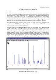
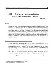
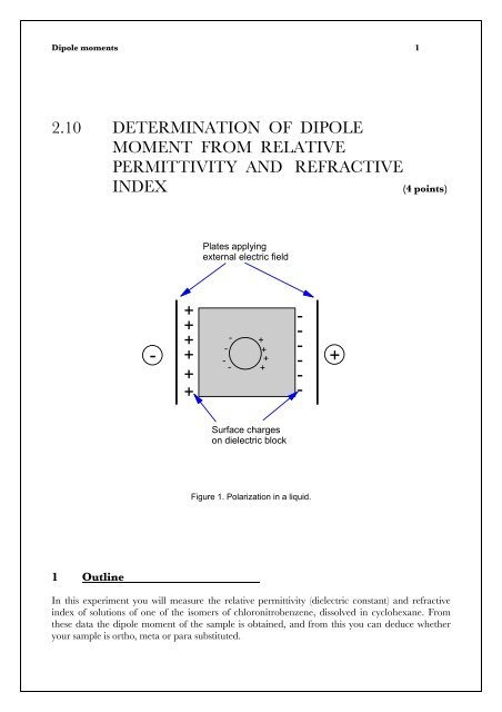
Figure 1. Polarization in a liquid.<br />
1 Outline<br />
In this experiment you will measure the <strong>relative</strong> <strong>permittivity</strong> (dielectric constant) <strong>and</strong> refractive<br />
index <strong>of</strong> solutions <strong>of</strong> one <strong>of</strong> the isomers <strong>of</strong> chloronitrobenzene, dissolved in cyclohexane. From<br />
these data the <strong>dipole</strong> <strong>moment</strong> <strong>of</strong> the sample is obtained, <strong>and</strong> <strong>from</strong> this you can deduce whether<br />
your sample is ortho, meta or para substituted.
Dipole <strong>moment</strong>s 2<br />
2 Safety<br />
Chloronitrobenzenes are poisonous: avoid skin contact <strong>and</strong> inhalation. Use the fume cupboard<br />
when you prepare the solutions <strong>and</strong> wear disposable gloves whenever you are h<strong>and</strong>ling the solid<br />
or any solution <strong>of</strong> it. Clean up all waste after use <strong>and</strong> any spills immediately.<br />
Cyclohexane-air mixtures are explosive; dispose <strong>of</strong> cyclohexane solutions in the residues bottle<br />
provided. To encourage the solid to dissolve, you may warm the cyclohexane/chloronitrobenzene<br />
mixture, but do this using hot water, not a Bunsen burner (cyclohexane is highly flammable!)<br />
The URL for this experiment is http://ptcl.chem.ox.ac.uk/~hmc/tlab/experiments/210.html<br />
3 Theory<br />
In most molecules the centre <strong>of</strong> negative charge due to the electrons does not coincide with the<br />
centre <strong>of</strong> positive charge due to the nuclei. These molecules possess a permanent electric <strong>dipole</strong><br />
<strong>moment</strong> p. If charges -q <strong>and</strong> +q are separated by a distance r, the <strong>dipole</strong> <strong>moment</strong> has magnitude<br />
p = q r (1)<br />
The <strong>dipole</strong> is drawn <strong>from</strong> positive to negative charge, indicating the direction <strong>of</strong> electron drift.<br />
The polarization P <strong>of</strong> a sample is the average <strong>dipole</strong> <strong>moment</strong> per unit volume. In a dielectric<br />
sample, (or just “dielectric”), induction <strong>of</strong> electric charge occurs when the substance is placed in an<br />
electric field. If the molecules in the dielectric are oriented r<strong>and</strong>omly, P will be zero. However in<br />
the presence <strong>of</strong> an electric field they tend to line up so as to counteract the applied field, as shown<br />
in Figure 1. As the <strong>dipole</strong> <strong>moment</strong> per unit volume is equal to the charge per unit area, surface<br />
charges appear on a block <strong>of</strong> polarized dielectric.<br />
The <strong>relative</strong> <strong>permittivity</strong> ε r <strong>of</strong> a sample is the ratio <strong>of</strong> the field strength in vacuum to that in the<br />
material for the same distribution <strong>of</strong> charge. ε r is equal to ε/ε o , where ε is the <strong>permittivity</strong> <strong>of</strong> the<br />
sample, <strong>and</strong> ε o the <strong>permittivity</strong> <strong>of</strong> a vacuum (which is almost equal to that <strong>of</strong> air). ε r is also equal to<br />
the ratio <strong>of</strong> the capacitance C <strong>of</strong> a cell filled with sample to the capacitance C o <strong>of</strong> the cell when<br />
evacuated.<br />
ε C<br />
ε<br />
r<br />
= = (2)<br />
o o<br />
ε C<br />
Capacitance is increased by the presence <strong>of</strong> a polarizable medium; typical values <strong>of</strong> ε r are 1.00<br />
(air), 5.94 (chlorobenzene) <strong>and</strong> 15.5 (liquid ammonia). Water has the unusually high value <strong>of</strong> 80,<br />
<strong>and</strong> this high value has important consequences for the rate <strong>of</strong> reactions between charged species<br />
in aqueous solution, since the field around an ion falls away very rapidly with distance if the<br />
dielectric constant is high.<br />
Suppose that a unit positive charge in the dielectric medium is situated at the centre <strong>of</strong> a small<br />
empty sphere. The size <strong>of</strong> this sphere, exaggerated in Figure 1, is large compared to molecular
Dipole <strong>moment</strong>s 3<br />
dimensions but is small in relation to the distance between the plates, so the material beyond it<br />
can be treated as a continuum. The local field intensity acting on this unit charge is<br />
4<br />
F = 4πσ − 4πP+ πP<br />
(3)<br />
3<br />
The three components <strong>of</strong> F are, respectively, the force due to the charges on the plates with<br />
charge density σ, the induced charges on the material facing the plates which partly counteract<br />
the applied field, <strong>and</strong> the charges on the surface <strong>of</strong> the small spherical cavity which enhance the<br />
applied field.<br />
From this can be derived the Clausius-Mosotti equation:<br />
ε<br />
r<br />
−1 M 4π L<br />
= P = α<br />
ε + 2 ρ 3<br />
r<br />
(4)<br />
where M is the molar mass <strong>of</strong> the sample, ρ its density, <strong>and</strong> L is Avogadro's constant. Because <strong>of</strong><br />
thermal motion, the molecules do not orientate themselves in a completely ordered fashion, but<br />
instead take up a range <strong>of</strong> positions at an angle θ to the electric field. The potential energy U <strong>of</strong><br />
each molecule is given by<br />
U = − pEcosθ<br />
(5)<br />
According to Boltzmann's law, the number <strong>of</strong> molecules distributed with the axes <strong>of</strong> their <strong>dipole</strong>s<br />
−U / kT<br />
pointing in the directions within the solid angle dΩ is Ae dΩ , where A is proportional to the<br />
number <strong>of</strong> molecules. From this we may obtain the average <strong>moment</strong> per molecule as a series<br />
expression. Taking the first non-zero term only, <strong>and</strong> considering the relation between the mean<br />
<strong>moment</strong> <strong>and</strong> the polarization, we obtain the Debye equation:<br />
P<br />
or<br />
2<br />
4π<br />
Lp<br />
= (6)<br />
kT<br />
The polarization caused by the alignment <strong>of</strong> molecules with permanent <strong>dipole</strong> <strong>moment</strong>s is termed<br />
the orientation polarization, P or . It is one <strong>of</strong> three effects which contribute to the total polarization,<br />
P. A second effect, the electronic polarization P el , arises <strong>from</strong> displacement <strong>of</strong> the electron cloud by<br />
the field, while the third, distortion polarization P d , arises <strong>from</strong> the stretching <strong>and</strong> bending <strong>of</strong> the<br />
nuclear framework caused by the field.<br />
el + d + or<br />
Total polarisation<br />
el + d<br />
el<br />
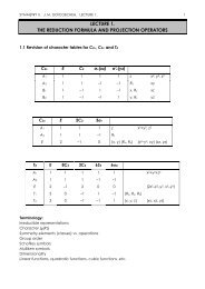
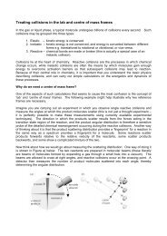
Fig. 2. The change <strong>of</strong> polarization with frequency.<br />
R f Miicrowave IR Visible UV
Dipole <strong>moment</strong>s 4<br />
The dependence <strong>of</strong> the three components <strong>of</strong> the polarization on frequency <strong>of</strong> the applied field is<br />
shown in Figure 2.<br />
At low frequencies, all three effects are present. As the frequency is increased into the infrared<br />
region, molecules no longer have time to orient, <strong>and</strong> the P or contribution drops out. In the visible<br />
region, the applied frequency is too high for molecular distortion to contribute to the polarization,<br />
<strong>and</strong> only P el remains.<br />
At X-ray frequencies even the electronic contribution drops out. Consequently, the refractive<br />
index <strong>of</strong> materials for X-rays is almost unity, <strong>and</strong> direct X-ray microscopy is made impractical<br />
because no lenses are available.<br />
At optical frequencies P el is the only component <strong>of</strong> the polarization <strong>and</strong> there is a simple<br />
relationship between <strong>relative</strong> <strong>permittivity</strong> <strong>and</strong> refractive index:<br />
2<br />
ε<br />
r<br />
= n<br />
(7)<br />
(Note that equation (7) applies only when P el is the sole contributor to the polarization.) P el may<br />
therefore be obtained by substituting this expression into the Clausius-Mosotti relation (4), to give<br />
the Lorentz equation:<br />
P<br />
el<br />
2<br />
n −1<br />
M<br />
=<br />
2<br />
n + 2 ρ<br />
(8)<br />
As P is the sum <strong>of</strong> the orientation, electronic <strong>and</strong> distortion polarization<br />
it follows <strong>from</strong> equation (6) that<br />
P= Por + Pel + Pd<br />
(9)<br />
2<br />
1 4π<br />
Lp<br />
P− Pel = Por + Pd = + P<br />
o<br />
d<br />
(10)<br />
4πε<br />
9kT<br />
The equations derived so far strictly apply only to gases, since interactions between molecules<br />
have been ignored. If this approximation is applied to a dilute solution <strong>of</strong> polar molecules in a<br />
non-polar solvent, then both ε r <strong>and</strong> 1/ρ, where ρ is the density <strong>of</strong> the solution, are almost linear<br />
functions <strong>of</strong> solute concentration. Therefore<br />
ε<br />
r<br />
− 1 x M + x M<br />
P= x1P1+ x2P2=<br />
ε + 2 ρ<br />
r<br />
1 1 2 2<br />
(11)<br />
where x is the mole fraction, <strong>and</strong> the subscripts 1 <strong>and</strong> 2 refer to the solvent <strong>and</strong> solute respectively.<br />
Employing the same reasoning used to obtain equation (8), we find that
Dipole <strong>moment</strong>s 5<br />
2<br />
n −1<br />
x1M1+<br />
x2M2<br />
xP<br />
1 el,1+ xP<br />
2 el,2 =<br />
2<br />
n + 2 ρ<br />
The concentration <strong>of</strong> solvent, c 1 , is related to its mole fraction by<br />
(12)<br />
c<br />
1<br />
=<br />
x1ρ<br />
x M + x M<br />
1 1 2 2<br />
(13)<br />
<strong>and</strong> there is a corresponding relation for c 2 . From equations (11), (12) <strong>and</strong> (13) :<br />
2<br />
2<br />
r<br />
1 n −1<br />
3(<br />
r<br />
)<br />
1<br />
−<br />
el,1 1+ 2<br />
−<br />
el,2 2<br />
= =<br />
2 2<br />
εr<br />
+ n + εr<br />
+ n +<br />
( P P ) c ( P P ) c<br />
ε −<br />
ε −n<br />
2 2 ( 2)( 2)<br />
(14)<br />
Applying equation (10) to each component in equation (14), <strong>and</strong> noting that for the solvent there<br />
is no <strong>dipole</strong> <strong>moment</strong>,<br />
2 2<br />
3( εr<br />
− n ) 1 4πLp2<br />
=<br />
2<br />
o c + P c + P c<br />
( ε + 2)( n + 2) 4πε<br />
9kT<br />
r<br />
2 d,1 1 d,2 2<br />
(15)<br />
The distortion polarization terms are assumed to be small <strong>and</strong> nearly constant. Thus a plot <strong>of</strong> the<br />
term on the left <strong>of</strong> equation (15) against c 2 (in mol m -3 ) will yield a line <strong>from</strong> whose slope we can<br />
obtain the <strong>dipole</strong> <strong>moment</strong>.<br />
Fixed<br />
frequency<br />
oscillator<br />
C meas<br />
Variable<br />
frequency<br />
oscillator<br />
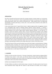
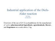
Figure 3. Apparatus used for the heterodyne beat method.<br />
4 Procedure<br />
You will measure capacitance using the heterodyne beat method. An oscillator provides a fixed<br />
frequency <strong>of</strong> 100 kHz, which is fed to the Y plates <strong>of</strong> an oscilloscope. A second oscillator,<br />
connected to the X plates <strong>of</strong> the scope, provides a variable frequency which is adjusted until a<br />
figure 8 (known as a Lissajous figure - see the link on the web page for this experiment) is traced<br />
on the oscilloscope screen. At this point the variable frequency is exactly double the fixed<br />
frequency.<br />
The variable frequency is controlled by the total capacitance C tot <strong>of</strong> an external circuit, as shown in<br />
the figure. C tot is equal to the sum <strong>of</strong> the capacitance <strong>of</strong> the cell, C cell , that <strong>of</strong> the precision
Dipole <strong>moment</strong>s 6<br />
measuring capacitor C meas , <strong>and</strong> the residual capacitance C resid <strong>of</strong> the leads <strong>and</strong> <strong>of</strong> the measuring<br />
capacitor at its zero position:<br />
C tot = C cell + C meas + C resid (16)<br />
When the Lissajous figure 8 is displayed, we know that C tot has reached a fixed value. C resid is also<br />
constant, so <strong>from</strong> equations (2) <strong>and</strong> (16) it follows that<br />
C cell + C meas = C o ε r + C meas = constant (17)<br />
where C o is the capacitance <strong>of</strong> the empty cell <strong>and</strong> ε r is the <strong>relative</strong> <strong>permittivity</strong> <strong>of</strong> the sample. The<br />
measuring capacitor is an earthed stepped rod which can be moved axially within a live cylinder<br />
by a micrometer screw. Its capacity C meas is directly proportional to the micrometer reading R. If<br />
the proportionality constant is k', then<br />
C o ε r + k' R = constant (18)<br />
We measure R for air (R o ), the pure solvent (R 1 ) <strong>and</strong> the solution (R). It follows <strong>from</strong> equation (18)<br />
that:<br />
R<br />
R<br />
− R ε<br />
r<br />
−ε<br />
=<br />
−R<br />
ε −ε<br />
o<br />
r,0<br />
o 1 r,1 r,0<br />
(19)<br />
This equation allows the <strong>relative</strong> <strong>permittivity</strong> <strong>of</strong> the solution ε r to be obtained <strong>from</strong> the<br />
capacitance readings R, given the <strong>relative</strong> permittivities <strong>of</strong> the pure components, ε r,0 <strong>and</strong> ε r,1 .<br />
Your sample is a chloronitrobenzene <strong>of</strong> molar mass 157.5 g mol -1 . Prepare four solutions as<br />
follows: First put on a clean pair <strong>of</strong> protective gloves. Accurately weigh about 2g sample in a<br />
weighing bottle. Tip the contents into a clean, dry 100 cm 3 volumetric flask <strong>and</strong> re-weigh the<br />
weighing bottle. Dissolve the solid in about 50 cm 3 cyclohexane. Dissolution is slow in cold<br />
cyclohexane but rapid if the temperature is raised a few degrees.<br />
ON NO ACCOUNT SHOULD YOU HEAT THE CYCLOHEXANE OVER A BUNSEN BURNER!<br />
Instead, dip the flask into a beaker <strong>of</strong> hot water. Make up to the mark once the solid has dissolved.<br />
Prepare further solutions containing roughly 3g, 4g <strong>and</strong> 5g solid in 100 cm 3 cyclohexane.<br />
Measure the <strong>relative</strong> permittivities <strong>of</strong> air, the solvent <strong>and</strong> the solutions as follows:<br />
1. Switch on the capacity meter <strong>and</strong> water bath <strong>and</strong> allow them 30 minutes to warm up. The<br />
water bath should be set to a temperature within the range 24 - 30 C.<br />
2. Switch on the oscilloscope. Do not use the scope with brightness greater than necessary, or<br />
the screen may be burnt.<br />
3. Clamp a volumetric flask containing cyclohexane <strong>and</strong> the flasks containing the sample<br />
solutions in the water bath to equilibrate. Place a clean, empty tall 50 cm 3 beaker in the
Dipole <strong>moment</strong>s 7<br />
brass thermostat jacket <strong>and</strong> carefully bring it up under the cylindrical plates <strong>of</strong> the cell.<br />
Rest the beaker <strong>and</strong> jacket on the wooden block provided. Be careful not to move the cell<br />
itself, or you will change the capacity <strong>of</strong> the leads. Wait for five minutes for thermal<br />
equilibrium, then adjust the measuring condenser using the knobs on the right h<strong>and</strong> side<br />
to give a figure 8 on the oscilloscope. Make all final adjustments in the same direction to<br />
minimize backlash errors. The meter is sensitive to vibration <strong>and</strong> it readily picks up the<br />
minute changes in capacitance caused by your body, so it may not be possible to tune a<br />
precisely stationary figure 8. Record the air reading, R o (this will be approximately 38).<br />
4. Fill the beaker with pure cyclohexane (taken <strong>from</strong> your thermally equilibrated supply)<br />
through a funnel inserted in the hole at the top <strong>of</strong> the cell. The liquid should reach to the<br />
lower edges <strong>of</strong> the vents cut in the outer tube <strong>of</strong> the cell under the lid, so that the inner<br />
tube is fully immersed. Allow a couple <strong>of</strong> minutes for thermal equilibrium to be reestablished,<br />
then take the cyclohexane reading.<br />
5. Withdraw the beaker <strong>of</strong> cyclohexane in the jacket <strong>from</strong> the cell. Replace the beaker by a<br />
clean one <strong>and</strong> repeat the procedure with the chloronitrobenzene solutions, washing the<br />
cell with cyclohexane between readings.<br />
6. While waiting for thermal equilibrium to be attained, measure the refractive indices <strong>of</strong> the<br />
solutions using the refractometer provided. You will find it helpful to use the refractometer<br />
first with water, which readily gives a clear image. The solutions you will later measure are<br />
slightly (but not much) more difficult to measure, as they evaporate more readily. Use the<br />
refractometer as follows:<br />
Turn on the adjustable lamp <strong>and</strong> position it so it illuminates the back <strong>of</strong> the prism<br />
assembly. Open the prism box <strong>and</strong> place a few drops <strong>of</strong> liquid on the ground surface <strong>of</strong> the<br />
lower prism. Close <strong>and</strong> fasten the prism box, so that the liquid is squeezed into a thin film;<br />
to obtain a good reading the film should extend across the entire closed region <strong>of</strong> the<br />
prism.<br />
Focus the crosswires <strong>of</strong> the eyepiece, adjust the illumination if necessary, then gently turn<br />
the prism box using the rear knurled wheel until a coloured b<strong>and</strong> appears in the field <strong>of</strong><br />
view. By turning the milled wheel at the base <strong>of</strong> the telescope, a position will be found at<br />
which the coloured b<strong>and</strong> will be eliminated, the field <strong>of</strong> view being partly light <strong>and</strong> partly<br />
dark, with a sharp dividing line. Bring this sharp line into coincidence with the intersection<br />
<strong>of</strong> the crosswires <strong>and</strong> read the refractive index by means <strong>of</strong> the magnifier. The scale is<br />
divided to the third decimal place, the fourth being obtained by estimation.<br />
7. At the end <strong>of</strong> the experiment leave the instruments clean. Switch <strong>of</strong>f all power.
Dipole <strong>moment</strong>s 8<br />
5 Useful information<br />
The <strong>relative</strong> <strong>permittivity</strong> <strong>of</strong> air, ε r,0 is 1.00, <strong>and</strong> that <strong>of</strong> cyclohexane, ε r,1 is [2.023 - 0.0016 (t-20)],<br />
in which t is the temperature in o C. The <strong>dipole</strong> <strong>moment</strong> <strong>of</strong> chlorobenzene is 1.60D (in which<br />
direction must this be?), <strong>and</strong> that <strong>of</strong> nitrobenzene is 4.01D in the direction C → NO 2 . 1 Debye =<br />
3.38 % 10 -30 C m.<br />
6 Calculations<br />
Calculate the <strong>relative</strong> <strong>permittivity</strong> <strong>of</strong> the solutions using equation (19). Use your calculated values<br />
<strong>of</strong> <strong>relative</strong> <strong>permittivity</strong> <strong>and</strong> your measurements <strong>of</strong> refractive index to calculate the <strong>dipole</strong> <strong>moment</strong><br />
<strong>of</strong> the chloronitrobenzene (equation 15). Calculate the <strong>dipole</strong> <strong>moment</strong>s <strong>of</strong> ortho, meta <strong>and</strong> para<br />
chloronitrobenzene by vector addition <strong>and</strong> thus determine whether your sample is ortho, meta or<br />
para. Discuss sources <strong>of</strong> error in this experiment, <strong>and</strong> their magnitude.<br />
7 References<br />
1. Dielectric Behaviour <strong>and</strong> Structure, C.P.Smyth, McGraw-Hill, New York (1955), ch. 1. or<br />
Determination <strong>of</strong> Dipole Moments, C.P.Smyth; in Techniques <strong>of</strong> Chemistry (ed.<br />
A.Weissberger <strong>and</strong> B.W.Rossiter), Vol. IV, 397, Wiley Interscience, New York, 1972.<br />
2. Some Electrical <strong>and</strong> Optical Aspects <strong>of</strong> Molecular Behaviour, M.Davies, Pergamon Press, (Oxford<br />
(1965), ch. 1 - 3.<br />
3. The <strong>determination</strong> <strong>of</strong> <strong>dipole</strong> <strong>moment</strong>s in solution, H.B. Thompson, J. Chem. Educ., 43, 66<br />
(1966).<br />
4. Determination <strong>of</strong> Organic Structures by Physical Methods, ed. E.A.Braude <strong>and</strong> F.C.Nachod,<br />
Academic Press, New York (1955), ch. 9 by L.E.Sutton.
Dipole <strong>moment</strong>s 9<br />
8 Problems <strong>and</strong> solutions<br />
Observation Indicates Solution<br />
Lissajous figure<br />
completely absent<br />
Trace appears on scope<br />
but Lissajous figure will<br />
not remain fixed or the<br />
trace appears to be<br />
smudged.<br />
No boundary can be<br />
seen on the<br />
refractometer<br />
Lissajous figure appears<br />
but is not stable;<br />
constant readjustment<br />
<strong>of</strong> the slider is required<br />
Connections to<br />
oscilloscope faulty or<br />
‘scope not turned on<br />
Tuning <strong>of</strong> capacitance<br />
meter is not exact<br />
Refractometer<br />
incorrectly adjusted or<br />
insufficient sample<br />
present<br />
Capacitance <strong>of</strong> the<br />
sample is changing<br />
(i) Check connections.<br />
(ii) Check that ‘scope is plugged in <strong>and</strong> turned<br />
on.<br />
(iii) Check that intensity or brightness control is<br />
turned up.<br />
The display on the ‘scope is extremely sensitive<br />
to changes in capacitance.<br />
(i) Move away <strong>from</strong> the region close to the<br />
sample so that your body does not affect the<br />
readings.<br />
(ii) Try first using a beaker with no liquid in it;<br />
the air reading should be near to 38. When you<br />
have turned the moveable slider to a figure close<br />
to this, scan quite slowly, watching the display as<br />
you do so; it is easy to scan through the point at<br />
which the figure appears.<br />
(i) The refractive index for water is around 1.33.<br />
Adjust the prism position to a value close to this<br />
<strong>and</strong> check that the boundary has appeared.<br />
(ii) Check that liquid covers the prism area at the<br />
back <strong>of</strong> the instrument. If the glass plate is only<br />
partly covered the boundary will be weaker.<br />
(iii) Check that the light providing rear<br />
illumination is positioned so as to shine on the<br />
prism.<br />
(i) Move away <strong>from</strong> the region close to the<br />
sample - your body may be affecting the results.<br />
(ii) The sample has not reached thermal<br />
equilibrium - check that the water bath is not<br />
heating up without limit.
Dipole <strong>moment</strong>s 10<br />
9 Summary <strong>of</strong> symbols used in the theory<br />
Sub <strong>and</strong> superscripts o <strong>and</strong> 1 refer to air (or vacuum) <strong>and</strong> solvent respectively.<br />
p<br />
q<br />
r<br />
P<br />
P or<br />
P el<br />
P d<br />
R<br />
R o<br />
R 1<br />
E<br />
ε r<br />
ε<br />
ε o<br />
C o<br />
C cell<br />
C rot<br />
C resid<br />
C meas<br />
F<br />
σ<br />
M<br />
ρ<br />
L<br />
θ<br />
U<br />
n<br />
x<br />
c<br />
electric <strong>dipole</strong> <strong>moment</strong><br />
charge<br />
charge separation<br />
polarization<br />
orientation polarization<br />
electronic polarization<br />
distortion polarization<br />
micrometer reading, sample<br />
micrometer reading, air<br />
micrometer reading, pure cyclohexane<br />
electric field<br />
<strong>relative</strong> <strong>permittivity</strong><br />
<strong>permittivity</strong><br />
<strong>permittivity</strong> <strong>of</strong> vacuum<br />
capacitance <strong>of</strong> evacuated cell<br />
capacitance <strong>of</strong> cell<br />
capacitance <strong>of</strong> external circuit<br />
residual capacitance<br />
capacitance <strong>of</strong> measuring capacitor<br />
local field density<br />
charge density on plates<br />
molar mass <strong>of</strong> sample<br />
density <strong>of</strong> sample<br />
Avogadro's constant<br />
angle to electric field<br />
potential energy <strong>of</strong> molecule<br />
refractive index<br />
mole fraction<br />
concentration<br />
Thursday, October 25, 2007