A Home-made Ultrasonic Power Line Arc Detector - ARRL
A Home-made Ultrasonic Power Line Arc Detector - ARRL
A Home-made Ultrasonic Power Line Arc Detector - ARRL

You also want an ePaper? Increase the reach of your titles
YUMPU automatically turns print PDFs into web optimized ePapers that Google loves.
E<br />
ven though BPL interference has<br />
captured the headlines for some<br />
time now, amateurs continue to be<br />
bothered by old-fashioned power<br />
line noise. In some areas, power line noise<br />
problems are actually getting worse due to<br />
utility company maintenance budget limitations.<br />
A call to your local power company<br />
should be all that it takes to resolve power<br />
line noise problems. Radiation from leaky<br />
power equipment is a nonintended emitter<br />
in FCC speak and the power companies are<br />
required to address the issue. Unfortunately,<br />
in real life, an amateur is much more likely<br />
to achieve prompt resolution if he can point<br />
the power company towards the source of<br />
the noise. The relatively simple receiver<br />
described here can help you do exactly that.<br />
Helping the <strong>Power</strong> Company will<br />
Help You<br />
Due to the various potential sources of<br />
radio noise, it is advisable to do some investigation<br />
before contacting the utility company.<br />
For one thing, it is possible that the noise being<br />
picked up may not be power line noise at all,<br />
and it is also possible that the noise is coming<br />
from something in the amateur’s own house<br />
or a close neighbor’s house. Examples of<br />
possible noise sources include light dimmers,<br />
switching power supplies, electric fences, and<br />
even doorbells. Some utility companies have<br />
limited capability to pinpoint the source of<br />
noise, so anything the ham can do to locate the<br />
problem will only help to resolve the problem.<br />
It also happens that many noise sources are<br />
moisture dependent, so if you have a problem<br />
on rainy days and the investigative crews<br />
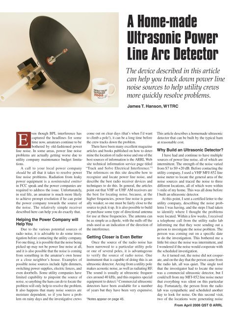
A <strong>Home</strong>-<strong>made</strong><br />
<strong>Ultrasonic</strong> <strong>Power</strong><br />
<strong>Line</strong> <strong>Arc</strong> <strong>Detector</strong><br />
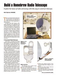
The device described in this article<br />
can help you track down power line<br />
noise sources to help utility crews<br />
more quickly resolve problems.<br />
James T. Hanson, W1TRC<br />
come out on clear days (that’s when I’d want<br />
to climb a pole!), it can be a long time before<br />
the crew tracks down the problem.<br />
There have been many excellent magazine<br />
articles and books published on how to determine<br />
the location of radio noise and one of the<br />
best sources of information is the <strong>ARRL</strong> Web<br />
site technical information service page titled<br />
“Track and Solve Electrical Interference.” 1<br />
The references on this site describe how to<br />
recognize and locate power line noise, and<br />
describe the best radio receiver devices and<br />
techniques to do this. In general, the articles<br />
point out that VHF or UHF AM receivers are<br />
the best for locating noise, because, at the<br />
higher frequencies, power line noise is generally<br />
weaker, so one must be fairly close to the<br />
source to pick it up. It is also possible to build<br />
or purchase some type of directional antenna<br />
for use at these frequencies. The antenna can<br />
be as simple as a dipole, with the nulls off the<br />
ends used as an indication of the direction of<br />
the interference.<br />
Getting Closer is Even Better<br />
Once the source of the radio noise has<br />
been narrowed to a particular utility pole<br />
or one of several poles, it is advantageous<br />
to verify the source of radio noise. One<br />
instrument that is capable of doing this is an<br />
ultrasonic detector. <strong>Arc</strong>ing from a utility pole<br />
makes acoustic noise, as well as radiating RF.<br />
The sound is usually at ultrasonic frequencies<br />
around 40 kHz, and this requires special<br />
equipment to detect. 2 Commercial ultrasonic<br />
detectors have been available for a number<br />
of years but they have been very expensive.<br />
1 Notes appear on page 45.<br />
This article describes a home<strong>made</strong> ultrasonic<br />
detector that can be built by the typical ham<br />
at reasonable cost.<br />
Why Build an <strong>Ultrasonic</strong> <strong>Detector</strong>?<br />
I have had and continue to have multiple<br />
sources of power line noise, all of which are<br />
intermittent. The strength of the noise varied<br />
from S7 to S9 +20 dB. Before contacting the<br />
utility company, I used a VHF MFJ-852 line<br />
noise meter to locate the general area of the<br />
noise sources and traced the noise to three<br />
different locations, all of which were within<br />
1 ⁄4 mile of my home. This was all done before<br />
I built an ultrasonic detector.<br />
At this point, I sent a certified letter to the<br />
utility company, describing the noise problems<br />
I was having, and the steps I had taken<br />
to identify where I thought the problems<br />
were located. Within a few weeks, I received<br />
a telephone call from the utility radio lab<br />
informing me that they were sending out a<br />
person to investigate the noise problem. The<br />
person was coming out on a specific date<br />
to do the investigation. This bothered me a<br />
little bit since the noise was intermittent, and<br />
I wondered if the noise would cooperate with<br />
the scheduled investigation.<br />
As it turned out, the noise did not cooperate,<br />
and on the day that the person came from<br />
the radio lab, all was quiet. The single tool<br />
that the investigator had to locate the noise<br />
was a commercial ultrasonic detector, but I<br />
could tell from my MFJ-852 line noise meter<br />
that everything was silent on this particular<br />
day. Fortunately, the person from the radio<br />
lab was sympathetic and scheduled another<br />
day to look for noise. On this second visit,<br />
two of the locations were generating noise<br />
From April 2006 QST © <strong>ARRL</strong>
at full blast, and the investigator found two<br />
sources of arcing at both locations. A work<br />
crew was scheduled to do the repairs.<br />
Unfortunately, the work that was initially<br />
done by the repair crew did not solve the noise<br />
problem. Prior to the work, I had decided to<br />
build an ultrasonic detector for myself. This<br />
was an instrument that the utility company<br />
used and understood, and I could do my own<br />
independent investigation of exactly where<br />
the noise was coming from when the noise<br />
was present. After I continued to experience<br />
noise problems following the completion of<br />
the initial repair work, I was able to go to<br />
the locations on days that I was experiencing<br />
noise and was able to not only locate the pole<br />
but also the location on the pole that had the<br />
source of the arcing. After reporting this to the<br />
utility radio lab, they <strong>made</strong> additional trips to<br />
the site and were able to verify my measurements<br />
so additional repair work was done.<br />
The occurrence of noise has been substantially<br />
reduced, and the utility company has promised<br />
to clear up any remaining problems.<br />
One of the features of an ultrasonic detector<br />
that makes it so valuable is its narrow<br />
beam-width. The 18 inch parabolic dish that<br />
I used has a directional beam width of about<br />
1.5°. Because of this narrow beam width, it is<br />
possible to determine not only which pole has<br />
arcing, but also where on the pole the arcing<br />
is coming from. It is also surprising how loud<br />
the arcing can be. I have had the experience of<br />
being able to easily detect arcing from a pole<br />
while standing across the street from the pole<br />
that had an arcing insulator.<br />
The <strong>Ultrasonic</strong> <strong>Detector</strong> Details<br />
One of the first things I did when I decided<br />
to build an ultrasonic detector was an Internet<br />
search for construction details. I found that<br />
there is a large group of hobbyists who have<br />
built electronic detectors that could detect<br />
the ultrasonic sound of bats (the flying kind).<br />
The detectors fall into several general categories.<br />
One type of detector simply amplifies<br />
the high frequency bat signal and feeds the<br />
amplified output into a threshold comparator<br />
followed by a frequency divider to generate a<br />
lower frequency signal within the frequency<br />
range of the human ear. A second type of<br />
detector is classified as a frequency translator.<br />
These detectors operate like a direct conversion<br />
receiver and simply amplify and then mix<br />
the ultrasonic signal with a local oscillator to<br />
heterodyne the ultrasonic signal to audio frequencies,<br />
which can be heard with earphones.<br />
Because it preserves the amplitude and sound<br />
characteristics of the ultrasonic signal, this is<br />
the type of detector that I decided to build. A<br />
simplified block diagram of the detector is<br />
included in Figure 1.<br />
The heart of the detector is a parabolic<br />
dish and a transducer capable of picking up<br />
ultrasonic sound. Several companies make<br />
low cost transducers that have a peak response<br />
From April 2006 QST © <strong>ARRL</strong><br />
at 40 kHz. This is fortunate, since this is also<br />
the frequency at which power line arcs are<br />
readily detected. The transducer I used was<br />
the Kobitone 255-400ER18, a stock item at<br />
Mouser Electronics. The output of the ultrasonic<br />
transducer is amplified in a low noise<br />
preamplifier and is then fed to a mixer in<br />
which the signal is heterodyned to audio frequencies<br />
by mixing with an oscillator that is<br />
offset from the 40 kHz ultrasonic signal. The<br />
resultant audio signal is filtered in a simple<br />
low pass filter and amplified to produce an<br />
Figure 1 — Simplified block diagram of the ultrasonic detector.<br />
Figure 2 — <strong>Ultrasonic</strong> dish assembly.<br />
audio output to a pair of earphones. The electronics<br />
operate from a single 9 V battery.<br />
The parabolic dish assembly is a modification<br />
of a design that was built by Greg<br />
Kunkel. 3 In his original application, Greg used<br />
an audio microphone and a recorder to pick up<br />
and record bird songs. The beauty of Greg’s<br />
design is that it uses an off-the-shelf Edmund<br />
Scientific parabolic dish and low cost, readily<br />
available PVC pipe fittings for the assembly.<br />
The modifications that I <strong>made</strong> to adapt the<br />
design for an ultrasonic detector included:
• In the original design, the microphone was<br />
held in place with elastic bands. The reason<br />
for this was to isolate the microphone<br />
from the mechanical assembly. I wanted<br />
something that would be more rugged, so<br />
the design modification for ultrasonic use<br />
uses a piece of the same 1 ⁄8 inch rubber<br />
gasket material used for the PVC gaskets<br />
to support the ultrasonic sensor.<br />
• I added a 3 ⁄8 inch hole in the back of the<br />
PVC T connector. This provides a shorter<br />
path for the shielded wire from the sensor<br />
to the electronics and also provides a sight<br />
so that you can see in the direction that<br />
the sensor is pointed.<br />
• I increased the length of the top PVC pipe<br />
to provide a better place to hold the complete<br />
assembly.<br />
Putting it Together<br />
All of the components of the mechanical<br />
assembly are shown in Figure 2. The Edmund<br />
Scientific parabolic dish is key to building a<br />
successful ultrasonic detector. This is an<br />
18 inch aluminum dish with a 1.13 inch center<br />
hole and a 4.5 inch focal length. The center<br />
hole is a good fit for the PVC threaded pipe<br />
assemblies. Rubber gaskets cut from 1 ⁄8 inch<br />
gasket material provide a tight fit for the PVC<br />
threaded pipefitting. The drawing for the gaskets<br />
and the transducer holder are included in<br />
Figure 3. I purchased the gasket material at a<br />
local hardware store.<br />
One thing that needs to be emphasized is<br />
the need to paint the parabolic dish. As the<br />
dish comes from Edmund Scientific, it is<br />
unpainted aluminum and it is quite an efficient<br />
reflector of light. One of the uses that<br />
Edmund Scientific advertises for the dish<br />
is a solar furnace. I tested this “feature” in<br />
February while the outside temperature was<br />
about 20°F. I poked a piece of wood through<br />
the dish hole and aimed the dish at the sun. In<br />
less than 30 seconds, the wood was smoking.<br />
It was scorched and would have burst into<br />
flame had I left it any longer. This convinced<br />
me to paint the dish, as I did not want to<br />
destroy the ultrasonic transducer if the dish<br />
were ever inadvertently aimed too close to the<br />
sun. I used a spray can of flat black paint to<br />
paint the dish. This greatly reduces the solar<br />
reflection but does not have any effect on the<br />
sound reflection characteristics of the dish.<br />
The ultrasonic transducer wants to be positioned<br />
so that its smooth detector side (opposite<br />
from the leads) is at the focus of the dish<br />
and pointed at the dish. The 4.5 inch dish focal<br />
length turns out to be the actual depth of the<br />
dish. Because of this, the focal point can be<br />
found very easily by simply placing a straightedge<br />
across the dish edges and aligning the<br />
depth of the transducer so that it is aligned<br />
with the edge of the straightedge.<br />
The electrical connection from the transducer<br />
is <strong>made</strong> with a length (about 12 inches)<br />
of small diameter (0.11 inch diameter)<br />
Figure 3 — Rubber washer and mounting plate details.<br />
Figure 4 — Transducer mounting details.<br />
shielded wire. I had some wire in my junk<br />
box but you can also use RG-174 coax, which<br />
is about the same diameter. The shielded wire<br />
is soldered directly to the transducer and the<br />
soldered connections keep the transducer<br />
positioned and locked to the rubber plate. The<br />
only critical part of the connection is to connect<br />
the shield of the coax to the transducer<br />
terminal that is electrically connected to the<br />
case of the transducer. This can be checked<br />
with an ohmmeter. I found that this was the<br />
shorter of the two pins on my transducer. An<br />
RCA audio plug is used on the end that connects<br />
to the electronic converter box. The<br />
RCA plug will fit through the 3 ⁄8 inch hole that<br />
is drilled in the PVC T so the connection can<br />
be soldered before the wire is passed through<br />
the PVC pipe.<br />
The details of the final ultrasonic transducer<br />
assembly mounted to the parabolic<br />
dish are shown in Figure 4. The shielded<br />
cable is held to one of the 10-24 rods with<br />
small plastic tie wraps. The 10-24 nuts are<br />
used to adjust the position of the transducer<br />
so that it is properly positioned at the focus<br />
of the parabolic dish.<br />
The schematic of the electronics is shown<br />
in Figure 5. The design is a modification of<br />
a downconverter that I found on one of the<br />
“Bat” Web sites. 4 The design shown in the<br />
schematic is based on one published in the<br />
December 1994 issue of Popular Electronics.<br />
I <strong>made</strong> several modifications to the original<br />
schematic, including the following:<br />
• The original circuit used an LMC567 low<br />
power tone decoder for the oscillator. I<br />
replaced this with a TLC555 CMOS 555<br />
timer chip operating in the multivibrator<br />
mode. The 555 is a very common chip and<br />
is readily available from multiple sources.<br />
• I reduced the oscillator tuning range from<br />
the original 7.5 to 88 kHz to a range of 30<br />
to 48 kHz. This covers the range required<br />
to detect 40 kHz arcing signals and makes<br />
setting of the oscillator much less critical.<br />
• I changed both of the preamplifier transistors<br />
from 2N3904 to 2N4401, which<br />
have a lower audio noise figure, and have<br />
become a favorite with audio enthusiasts.<br />
• I used a 6 1 ⁄4 × 3 3 ⁄4 × 2 inch plastic enclosure<br />
that I had to house the electronics. A<br />
cover plate was fabricated from a piece of<br />
scrap aluminum. RadioShack used to sell<br />
these housings with a cover plate, but it is<br />
no longer a RadioShack item. Keystone<br />
Electronics makes the same size box, and<br />
the box and an aluminum cover are available<br />
from Digi-Key. There is nothing<br />
critical about the box other than it needs<br />
to be able to hold the electronics and a<br />
9 V battery.<br />
The circuit was built on a RadioShack<br />
2 13 ⁄16 × 3 3 ⁄4 inch “universal component PC<br />
board” (part number 276-168). This board<br />
has 0.1 inch hole spacing, which will accept<br />
standard dip packages. It also has two separate<br />
buses, which are used for power and ground<br />
connections. Figure 6 is a photograph of the<br />
finished circuit. The layout is straightforward<br />
and follows the schematic.<br />
The input preamplifier section is in the<br />
lower left-hand corner of the picture and connects<br />
to the RCA input jack. Just to the right<br />
and slightly above is the mixer, and the audio<br />
amplifier section is to the far right. The oscillator<br />
is at the top of the board. The circuit<br />
board and all of the connectors and controls<br />
are mounted to the housing aluminum cover<br />
plate. I <strong>made</strong> some small rubber washers out<br />
of the same 1 ⁄8 inch rubber gasket material<br />
and used two at each corner to space the circuit<br />
board off the cover plate.<br />
I mounted the electronics enclosure to a<br />
From April 2006 QST © <strong>ARRL</strong>
Figure 5 — <strong>Ultrasonic</strong> detector schematic and parts list. Most components are stocked by RadioShack, www.radioshack.com;<br />
Mouser, www.mouser.com, or Digi-Key, www.digikey.com.<br />
BT1 — 9 V “transistor” battery.<br />
C1-C3 — 0.01 µF, 100 V subminiature<br />
polyester capacitor (Mouser 140-<br />
PM2A103K).<br />
C4 — 180 pF COG (NPO) multilayer<br />
ceramic (Mouser 80-C315C181J1G).<br />
C5 — 0.047 µF, 100 V subminiature<br />
polyester capacitor (Mouser<br />
140-PM2A473K).<br />
C6-C9 — 0.1 µF, 100 V subminiature<br />
polyester capacitor (Mouser<br />
140-PM2A104K).<br />
C10 — 470 µF, 25 V capacitor<br />
(Mouser 140-XRL25V470).<br />
C11 — 10 µF, 35 V capacitor<br />
(Mouser 140-XRL25V10).<br />
C12 — 47 µF, 35 V capacitor<br />
(Mouser 140-XRL25V47).<br />
J1 — Panel mount RCA jack<br />
(Mouser 161-1002).<br />
6 1 ⁄4 × 4 inch piece of 3 ⁄8 inch plywood and<br />
mounted the plywood to the PVC pipe with<br />
a pair of two hole galvanized tubing straps.<br />
The board was left over from a previous project.<br />
This arrangement allows the electronics<br />
box to be removed from the PVC pipe<br />
without opening the electronics box. The<br />
electronics box could be mounted directly to<br />
the PVC pipe without the plywood if desired.<br />
Figure 7 is a photo of the front panel. The<br />
rear view of the completed detector is shown<br />
in Figure 8.<br />
Testing Out the <strong>Detector</strong><br />
Plug a pair of 8 Ω headphones into the<br />
1 ⁄4 inch jack and turn on the power. You<br />
should hear a white noise rushing sound,<br />
which will change slightly as you adjust the<br />
From April 2006 QST © <strong>ARRL</strong><br />
J2 — 1 ⁄4 inch panel mount phone jack<br />
(Mouser 161-1804).<br />
P1 — Small RCA plug (Mouser 17PP050).<br />
Q1, Q2 — 2N4401 (Mouser 610-4401).<br />
Q3 — MPF102 (Mouser 512-MPF102).<br />
R1, R2 — 220 kΩ, 1 ⁄4 W (Mouser<br />
660-CF1/4L 224J).<br />
R3-R6 — 2.2 kΩ, 1 ⁄4 W (Mouser<br />
660-CF1/4L 222J).<br />
R7 — 1 kΩ, 1 ⁄4 W (Mouser 660-CF1/4L 102J).<br />
R8, R9 — 270 Ω, 1 ⁄4 W (Mouser 660-CF1/4L<br />
271J).<br />
R10, R11 — 10 kΩ, 1 ⁄4 W (Mouser<br />
660-CF1/4L 103J).<br />
R12 — 100 kΩ, 1 ⁄4 W (Mouser<br />
660-CF1/4L 104J).<br />
R13 — 82 kΩ, 1 ⁄4 W (Mouser<br />
660-CF1/4L 823J).<br />
R14 — 10 kΩ, audio control with SPST<br />
switch (Mouser 31XP401).<br />
frequency control. The only adjustment that<br />
has to be <strong>made</strong> is setting the frequency of the<br />
555 oscillator. Set the frequency to about 39<br />
kHz, which will tune the downconverter for a<br />
40 kHz input signal. There are several ways<br />
that the frequency can be set.<br />
I had an ultrasonic transmit transducer,<br />
which I connected to a signal generator<br />
adjusted for 40 kHz at a very low output. It<br />
was then a simple matter to aim the dish at<br />
the transmit transducer and adjust the frequency<br />
control until I could hear the audio<br />
tone in the earphones. I marked this point on<br />
the front panel so that I could easily set the<br />
oscillator to the correct frequency.<br />
You can also set the oscillator frequency<br />
with a frequency counter or an oscilloscope<br />
connected to the junction of R11 and C2.<br />
R15 — 50 kΩ, linear taper potentiometer<br />
(Mouser 31VA405).<br />
S1 — Part of R14.<br />
U1 — TLC555 CMOS 555 timer<br />
(RadioShack 276-1718).<br />
U2 — LM386 audio amplifier (RadioShack<br />
276-1731).<br />
<strong>Ultrasonic</strong> transducer, Kobitone<br />
255-400ER18 (Mouser 255-400ER18).<br />
Plastic enclosure — 6 1 ⁄4 × 3 3 ⁄4 × 2 inch,<br />
Keystone Electronics (Digi-Key 700K-ND).<br />
Cover — Plastic Enclosure Aluminum<br />
Keystone Electronics (Digi-Key<br />
2046K-ND).<br />
Universal component PC Board<br />
2 13 ⁄16 × 3 3 ⁄4 inch (RadioShack 276-168).<br />
Parabolic reflector — 18 inch diameter<br />
(Edmund Scientific 3080254).<br />
The following procedure, which does not<br />
require any special test equipment, can also<br />
be used. You can generate an ultrasonic signal<br />
by gently rubbing your fingers together.<br />
If you do this in front of the dish, you should<br />
be able to hear the sound quite loudly. Turn<br />
down the volume until you can just hear the<br />
sound of your rubbing fingers and carefully<br />
adjust the frequency control for the loudest<br />
sound. You may want to reduce the volume<br />
further as you make the final frequency<br />
adjustment. Place a mark on the front panel<br />
where the frequency control is. That is all<br />
there is to it — you are now ready to go hunting<br />
for arcing insulators on power lines.<br />
Using the <strong>Ultrasonic</strong> <strong>Detector</strong><br />
The <strong>Ultrasonic</strong> detector should not be
Figure 6 — <strong>Ultrasonic</strong> detector electronic assembly.<br />
used as the primary tool to hunt for power<br />
line noise. The techniques outlined in Notes<br />
1 and 2 should be followed to find the general<br />
area of the noise. I have been able to get the<br />
heading of the noise by rotating my triband<br />
beam while monitoring the noise on 10, 15<br />
or 20 meters with the receiver in the AM<br />
position. I have had some success finding<br />
the initial area by driving around with my car<br />
and listening to the AM radio tuned to the<br />
very high frequency end of the band. When<br />
I am in the vicinity of the noise, I have had<br />
very good luck using the MFJ-852 power<br />
line noise meter to narrow down the search.<br />
This VHF AM receiver has a signal strength<br />
meter with a 50 dB range and is very useful<br />
for tracking down the source. I have found<br />
that when I get close to the source of noise,<br />
the meter will be close to full scale.<br />
Once you are in the vicinity of the problem<br />
pole, it is time to bring out the ultrasonic<br />
detector. To aim the parabolic dish, site<br />
through the 3 ⁄8 inch hole drilled into the PVC<br />
T and center the ultrasonic transducer in the<br />
hole. There is enough of a gap around the<br />
transducer to allow you to see the wires and<br />
insulators on the pole. If arcing is occurring,<br />
you should hear a deep growl when<br />
you are pointing at the arcing source. The<br />
exact sound can be different, depending on<br />
the exact nature of the arcing. <strong>Arc</strong>ing can<br />
consist of single or multiple spikes at a 60 or<br />
120 Hz rate, and each will make a unique<br />
sound.<br />
If you read some of the reference material<br />
about ultrasonic detectors, they will mention<br />
that, if there is blockage between you and<br />
the arc, it will not be possible to hear the<br />
arc. My experience has been that, although<br />
the amplitude has varied, I have been able<br />
to hear the arc on all of the poles that I have<br />
investigated to date.<br />
The ultrasonic detector is only one of<br />
several tools that can be used to track down<br />
radio noise. An ultrasonic detector can get<br />
Figure 8 — Rear view of completed<br />
ultrasonic detector.<br />
you very close to determining the location<br />
of the problem on a pole. It is also a very<br />
good verification that a problem exists, but<br />
the final determination of what needs to be<br />
fixed and how to fix it should be left up to the<br />
utility company. Remember that they are the<br />
experts. The value of the ultrasonic detector<br />
is that it provides very good and convincing<br />
evidence that a problem exists on a given<br />
pole. It is very difficult for the utility company<br />
to ignore the fact that you are hearing<br />
actual arcing. It is also possible to record the<br />
New Products<br />
Figure 7 — <strong>Ultrasonic</strong> detector front panel.<br />
CWTOUCHKEYER P3 TOUCH PADDLE<br />
� The P3 touch paddle circuit board can be used to make<br />
your own touch-sensitive keyer paddle or straight key.<br />
Just add the conductive metal objects of your choice for<br />
the paddle contacts, and provide 5 to 14 V dc at 2 mA for<br />
power. The PC board measures 1.5×1 inches and paddle<br />
contacts can be mounted up to 24 inches away. Price: $28<br />
assembled or $18 in kit form. To order or for more information,<br />
visit www.touchpaddle.com or contact Sumner<br />
Eagerman, WA1JOS, 14 Boutas Dr, Norton, MA 02766;<br />
tel 508-285-7600.<br />
detector output and to convert the sound to an<br />
audio file if further proof is required.<br />
Good hunting!<br />
Notes<br />
1 “Track and Solve Electrical Interference,” www.<br />
arrl.org/tis/info/rfi-elec.html.<br />
2M. Loftness, KB7KK, AC <strong>Power</strong> Interference<br />
Handbook. Available from your <strong>ARRL</strong> dealer<br />
or the <strong>ARRL</strong> Bookstore, <strong>ARRL</strong> order no.<br />
9055, telephone 860-594-0355, or toll-free in<br />
the US 888-277-5289; www.arrl.org/shop/;<br />
pubsales@arrl.org.<br />
3G. Kunkel, “Parabolic Microphone Design,”<br />
web.archive.org/web/20041023131641/<br />
ourworld.compuserve.com/homepages/<br />
G_Kunkel/microphone.htm.<br />
4 “Bat <strong>Detector</strong>,” Popular Electronics, Dec 1994,<br />
www.njsas.org/projects/bat_detector/<br />
heterodyne.html.<br />
Jim Hanson, W1TRC, has been an <strong>ARRL</strong> member<br />
for over 50 years. He received his General<br />
class license in 1951, his Advanced class license<br />
in 1952 and his Amateur Extra class license in<br />
1984. His primary ham radio interest has been<br />
working DX and he is at the top of the phone and<br />
mixed DXCC honor roll. Jim has a BS degree<br />
in electrical engineering and has been retired<br />
from Raytheon Company Inc since 2004 where<br />
he worked on radar receiver and low noise<br />
exciter designs. He holds several patents relating<br />
to radar design. You can reach the author<br />
at 8 Ethelyn Circle, Maynard, MA 01754 or<br />
w1trc@arrl.net.<br />
From April 2006 QST © <strong>ARRL</strong>