A Home-made Ultrasonic Power Line Arc Detector - ARRL
A Home-made Ultrasonic Power Line Arc Detector - ARRL
A Home-made Ultrasonic Power Line Arc Detector - ARRL

Create successful ePaper yourself
Turn your PDF publications into a flip-book with our unique Google optimized e-Paper software.
at full blast, and the investigator found two<br />
sources of arcing at both locations. A work<br />
crew was scheduled to do the repairs.<br />
Unfortunately, the work that was initially<br />
done by the repair crew did not solve the noise<br />
problem. Prior to the work, I had decided to<br />
build an ultrasonic detector for myself. This<br />
was an instrument that the utility company<br />
used and understood, and I could do my own<br />
independent investigation of exactly where<br />
the noise was coming from when the noise<br />
was present. After I continued to experience<br />
noise problems following the completion of<br />
the initial repair work, I was able to go to<br />
the locations on days that I was experiencing<br />
noise and was able to not only locate the pole<br />
but also the location on the pole that had the<br />
source of the arcing. After reporting this to the<br />
utility radio lab, they <strong>made</strong> additional trips to<br />
the site and were able to verify my measurements<br />
so additional repair work was done.<br />
The occurrence of noise has been substantially<br />
reduced, and the utility company has promised<br />
to clear up any remaining problems.<br />
One of the features of an ultrasonic detector<br />
that makes it so valuable is its narrow<br />
beam-width. The 18 inch parabolic dish that<br />
I used has a directional beam width of about<br />
1.5°. Because of this narrow beam width, it is<br />
possible to determine not only which pole has<br />
arcing, but also where on the pole the arcing<br />
is coming from. It is also surprising how loud<br />
the arcing can be. I have had the experience of<br />
being able to easily detect arcing from a pole<br />
while standing across the street from the pole<br />
that had an arcing insulator.<br />
The <strong>Ultrasonic</strong> <strong>Detector</strong> Details<br />
One of the first things I did when I decided<br />
to build an ultrasonic detector was an Internet<br />
search for construction details. I found that<br />
there is a large group of hobbyists who have<br />
built electronic detectors that could detect<br />
the ultrasonic sound of bats (the flying kind).<br />
The detectors fall into several general categories.<br />
One type of detector simply amplifies<br />
the high frequency bat signal and feeds the<br />
amplified output into a threshold comparator<br />
followed by a frequency divider to generate a<br />
lower frequency signal within the frequency<br />
range of the human ear. A second type of<br />
detector is classified as a frequency translator.<br />
These detectors operate like a direct conversion<br />
receiver and simply amplify and then mix<br />
the ultrasonic signal with a local oscillator to<br />
heterodyne the ultrasonic signal to audio frequencies,<br />
which can be heard with earphones.<br />
Because it preserves the amplitude and sound<br />
characteristics of the ultrasonic signal, this is<br />
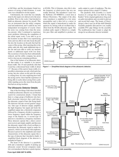
the type of detector that I decided to build. A<br />
simplified block diagram of the detector is<br />
included in Figure 1.<br />
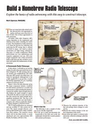
The heart of the detector is a parabolic<br />
dish and a transducer capable of picking up<br />
ultrasonic sound. Several companies make<br />
low cost transducers that have a peak response<br />
From April 2006 QST © <strong>ARRL</strong><br />
at 40 kHz. This is fortunate, since this is also<br />
the frequency at which power line arcs are<br />
readily detected. The transducer I used was<br />
the Kobitone 255-400ER18, a stock item at<br />
Mouser Electronics. The output of the ultrasonic<br />
transducer is amplified in a low noise<br />
preamplifier and is then fed to a mixer in<br />
which the signal is heterodyned to audio frequencies<br />
by mixing with an oscillator that is<br />
offset from the 40 kHz ultrasonic signal. The<br />
resultant audio signal is filtered in a simple<br />
low pass filter and amplified to produce an<br />
Figure 1 — Simplified block diagram of the ultrasonic detector.<br />
Figure 2 — <strong>Ultrasonic</strong> dish assembly.<br />
audio output to a pair of earphones. The electronics<br />
operate from a single 9 V battery.<br />
The parabolic dish assembly is a modification<br />
of a design that was built by Greg<br />
Kunkel. 3 In his original application, Greg used<br />
an audio microphone and a recorder to pick up<br />
and record bird songs. The beauty of Greg’s<br />
design is that it uses an off-the-shelf Edmund<br />
Scientific parabolic dish and low cost, readily<br />
available PVC pipe fittings for the assembly.<br />
The modifications that I <strong>made</strong> to adapt the<br />
design for an ultrasonic detector included: