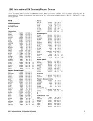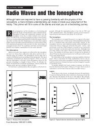
A Home-made Ultrasonic Power Line Arc Detector - ARRL
A Home-made Ultrasonic Power Line Arc Detector - ARRL
A Home-made Ultrasonic Power Line Arc Detector - ARRL

Create successful ePaper yourself
Turn your PDF publications into a flip-book with our unique Google optimized e-Paper software.
• In the original design, the microphone was<br />
held in place with elastic bands. The reason<br />
for this was to isolate the microphone<br />
from the mechanical assembly. I wanted<br />
something that would be more rugged, so<br />
the design modification for ultrasonic use<br />
uses a piece of the same 1 ⁄8 inch rubber<br />
gasket material used for the PVC gaskets<br />
to support the ultrasonic sensor.<br />
• I added a 3 ⁄8 inch hole in the back of the<br />
PVC T connector. This provides a shorter<br />
path for the shielded wire from the sensor<br />
to the electronics and also provides a sight<br />
so that you can see in the direction that<br />
the sensor is pointed.<br />
• I increased the length of the top PVC pipe<br />
to provide a better place to hold the complete<br />
assembly.<br />
Putting it Together<br />
All of the components of the mechanical<br />
assembly are shown in Figure 2. The Edmund<br />
Scientific parabolic dish is key to building a<br />
successful ultrasonic detector. This is an<br />
18 inch aluminum dish with a 1.13 inch center<br />
hole and a 4.5 inch focal length. The center<br />
hole is a good fit for the PVC threaded pipe<br />
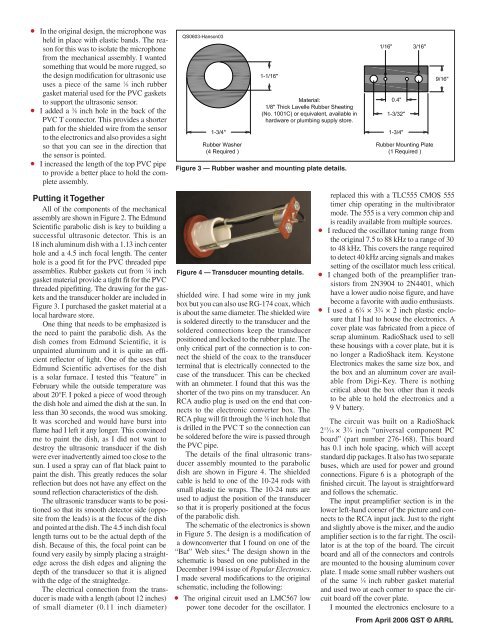
assemblies. Rubber gaskets cut from 1 ⁄8 inch<br />
gasket material provide a tight fit for the PVC<br />
threaded pipefitting. The drawing for the gaskets<br />
and the transducer holder are included in<br />
Figure 3. I purchased the gasket material at a<br />
local hardware store.<br />
One thing that needs to be emphasized is<br />
the need to paint the parabolic dish. As the<br />
dish comes from Edmund Scientific, it is<br />
unpainted aluminum and it is quite an efficient<br />
reflector of light. One of the uses that<br />
Edmund Scientific advertises for the dish<br />
is a solar furnace. I tested this “feature” in<br />
February while the outside temperature was<br />
about 20°F. I poked a piece of wood through<br />
the dish hole and aimed the dish at the sun. In<br />
less than 30 seconds, the wood was smoking.<br />
It was scorched and would have burst into<br />
flame had I left it any longer. This convinced<br />
me to paint the dish, as I did not want to<br />
destroy the ultrasonic transducer if the dish<br />
were ever inadvertently aimed too close to the<br />
sun. I used a spray can of flat black paint to<br />
paint the dish. This greatly reduces the solar<br />
reflection but does not have any effect on the<br />
sound reflection characteristics of the dish.<br />
The ultrasonic transducer wants to be positioned<br />
so that its smooth detector side (opposite<br />
from the leads) is at the focus of the dish<br />
and pointed at the dish. The 4.5 inch dish focal<br />
length turns out to be the actual depth of the<br />
dish. Because of this, the focal point can be<br />
found very easily by simply placing a straightedge<br />
across the dish edges and aligning the<br />
depth of the transducer so that it is aligned<br />
with the edge of the straightedge.<br />
The electrical connection from the transducer<br />
is <strong>made</strong> with a length (about 12 inches)<br />
of small diameter (0.11 inch diameter)<br />
Figure 3 — Rubber washer and mounting plate details.<br />
Figure 4 — Transducer mounting details.<br />
shielded wire. I had some wire in my junk<br />
box but you can also use RG-174 coax, which<br />
is about the same diameter. The shielded wire<br />
is soldered directly to the transducer and the<br />
soldered connections keep the transducer<br />
positioned and locked to the rubber plate. The<br />
only critical part of the connection is to connect<br />
the shield of the coax to the transducer<br />
terminal that is electrically connected to the<br />
case of the transducer. This can be checked<br />
with an ohmmeter. I found that this was the<br />
shorter of the two pins on my transducer. An<br />
RCA audio plug is used on the end that connects<br />
to the electronic converter box. The<br />
RCA plug will fit through the 3 ⁄8 inch hole that<br />
is drilled in the PVC T so the connection can<br />
be soldered before the wire is passed through<br />
the PVC pipe.<br />
The details of the final ultrasonic transducer<br />
assembly mounted to the parabolic<br />
dish are shown in Figure 4. The shielded<br />
cable is held to one of the 10-24 rods with<br />
small plastic tie wraps. The 10-24 nuts are<br />
used to adjust the position of the transducer<br />
so that it is properly positioned at the focus<br />
of the parabolic dish.<br />
The schematic of the electronics is shown<br />
in Figure 5. The design is a modification of<br />
a downconverter that I found on one of the<br />
“Bat” Web sites. 4 The design shown in the<br />
schematic is based on one published in the<br />
December 1994 issue of Popular Electronics.<br />
I <strong>made</strong> several modifications to the original<br />
schematic, including the following:<br />
• The original circuit used an LMC567 low<br />
power tone decoder for the oscillator. I<br />
replaced this with a TLC555 CMOS 555<br />
timer chip operating in the multivibrator<br />
mode. The 555 is a very common chip and<br />
is readily available from multiple sources.<br />
• I reduced the oscillator tuning range from<br />
the original 7.5 to 88 kHz to a range of 30<br />
to 48 kHz. This covers the range required<br />
to detect 40 kHz arcing signals and makes<br />
setting of the oscillator much less critical.<br />
• I changed both of the preamplifier transistors<br />
from 2N3904 to 2N4401, which<br />
have a lower audio noise figure, and have<br />
become a favorite with audio enthusiasts.<br />
• I used a 6 1 ⁄4 × 3 3 ⁄4 × 2 inch plastic enclosure<br />
that I had to house the electronics. A<br />
cover plate was fabricated from a piece of<br />
scrap aluminum. RadioShack used to sell<br />
these housings with a cover plate, but it is<br />
no longer a RadioShack item. Keystone<br />
Electronics makes the same size box, and<br />
the box and an aluminum cover are available<br />
from Digi-Key. There is nothing<br />
critical about the box other than it needs<br />
to be able to hold the electronics and a<br />
9 V battery.<br />
The circuit was built on a RadioShack<br />
2 13 ⁄16 × 3 3 ⁄4 inch “universal component PC<br />
board” (part number 276-168). This board<br />
has 0.1 inch hole spacing, which will accept<br />
standard dip packages. It also has two separate<br />
buses, which are used for power and ground<br />
connections. Figure 6 is a photograph of the<br />
finished circuit. The layout is straightforward<br />
and follows the schematic.<br />
The input preamplifier section is in the<br />
lower left-hand corner of the picture and connects<br />
to the RCA input jack. Just to the right<br />
and slightly above is the mixer, and the audio<br />
amplifier section is to the far right. The oscillator<br />
is at the top of the board. The circuit<br />
board and all of the connectors and controls<br />
are mounted to the housing aluminum cover<br />
plate. I <strong>made</strong> some small rubber washers out<br />
of the same 1 ⁄8 inch rubber gasket material<br />
and used two at each corner to space the circuit<br />
board off the cover plate.<br />
I mounted the electronics enclosure to a<br />
From April 2006 QST © <strong>ARRL</strong>