INSTALLATION INSTRUCTIONS - Pro Comp USA
INSTALLATION INSTRUCTIONS - Pro Comp USA
INSTALLATION INSTRUCTIONS - Pro Comp USA

You also want an ePaper? Increase the reach of your titles
YUMPU automatically turns print PDFs into web optimized ePapers that Google loves.
Revised: 12/2/2005<br />
<strong>INSTALLATION</strong><br />
<strong>INSTRUCTIONS</strong><br />
PARTS LIST:<br />
<strong>Pro</strong> <strong>Comp</strong> Suspension, Inc. Chula Vista, CA <strong>USA</strong><br />
Ph: (619) 216-1444 • Fax: (619) 216-1474 • E-Mail: tech@explorerprocomp.com • Website: www.explorerprocomp.com<br />
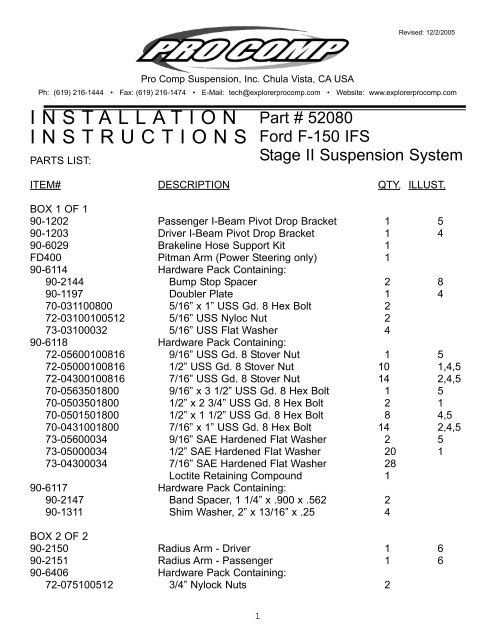
Part # 52080<br />
Ford F-150 IFS<br />
Stage II Suspension System<br />
ITEM# DESCRIPTION QTY. ILLUST.<br />
BOX 1 OF 1<br />
90-1202 Passenger I-Beam Pivot Drop Bracket 1 5<br />
90-1203 Driver I-Beam Pivot Drop Bracket 1 4<br />
90-6029 Brakeline Hose Support Kit 1<br />
FD400 Pitman Arm (Power Steering only) 1<br />
90-6114 Hardware Pack Containing:<br />
90-2144 Bump Stop Spacer 2 8<br />
90-1197 Doubler Plate 1 4<br />
70-031100800 5/16” x 1” USS Gd. 8 Hex Bolt 2<br />
72-03100100512 5/16” USS Nyloc Nut 2<br />
73-03100032 5/16” USS Flat Washer 4<br />
90-6118 Hardware Pack Containing:<br />
72-05600100816 9/16” USS Gd. 8 Stover Nut 1 5<br />
72-05000100816 1/2” USS Gd. 8 Stover Nut 10 1,4,5<br />
72-04300100816 7/16” USS Gd. 8 Stover Nut 14 2,4,5<br />
70-0563501800 9/16” x 3 1/2” USS Gd. 8 Hex Bolt 1 5<br />
70-0503501800 1/2” x 2 3/4” USS Gd. 8 Hex Bolt 2 1<br />
70-0501501800 1/2” x 1 1/2” USS Gd. 8 Hex Bolt 8 4,5<br />
70-0431001800 7/16” x 1” USS Gd. 8 Hex Bolt 14 2,4,5<br />
73-05600034 9/16” SAE Hardened Flat Washer 2 5<br />
73-05000034 1/2” SAE Hardened Flat Washer 20 1<br />
73-04300034 7/16” SAE Hardened Flat Washer 28<br />
Loctite Retaining <strong>Comp</strong>ound 1<br />
90-6117 Hardware Pack Containing:<br />
90-2147 Band Spacer, 1 1/4” x .900 x .562 2<br />
90-1311 Shim Washer, 2” x 13/16” x .25 4<br />
BOX 2 OF 2<br />
90-2150 Radius Arm - Driver 1 6<br />
90-2151 Radius Arm - Passenger 1 6<br />
90-6406 Hardware Pack Containing:<br />
72-075100512 3/4” Nylock Nuts 2<br />
1
NOTE: The following parts are used in conjunction with this kit, and must be ordered separately.<br />
ITEM# DESCRIPTION QTY. ILLUST.<br />
13130 Dual Add-A-Leaf (Rear Lift) 1<br />
7325 OR 3 Pc. Stainless Brake Hose Kit (90-94) 1<br />
7330 3 Pc. Stainless Brake Hose Kit (80-89) 1<br />
Alignment eccentrics, see catalog for applications 1<br />
4” Kit<br />
24412 OR Standard Cab Coil Springs 2 1<br />
24413 Extra Cab Coil Springs 2<br />
24612 Coil Springs (6” Lift) 2 1<br />
319510 Front Shock Absorbers 2 1<br />
326500 Rear Shock Absorber 2<br />
6” Kit<br />
24612 Standard Cab Coil Springs 2<br />
24613 Extra Cab Coil Springs 2<br />
321510 Front Shock Absorber 2 1<br />
326500 Rear Shock Absorber 2<br />
PLEASE NOTE: Acceptable Tire and Wheel Combinations:<br />
For the 4” 2WD applications: 31 x 10.50 x 15 on 15x 8 with 3.5 backspacing.<br />
For the 4” 4WD applications: 33 x 12.50 x 15, 16, or 17 on 15x8, 16x8, or 17x8 with 3.5<br />
backspacing<br />
For the 6” 2WD applications: 33 x 12.50 x 15, 16, 17 on 15x8, 16x8, or 17x8 with 3.5<br />
backspacing<br />
For the 6” 4WD applications: 35 x 12.50 x 15, 16, or 17 on 15x8, 16x8, or 17x8 with 3.5<br />
backspacing<br />
Any other tire and wheel combinations will not be endorsed as acceptable by <strong>Pro</strong> <strong>Comp</strong> suspension<br />
and will void any and all warranties, written or implied.<br />
PRIOR TO <strong>INSTALLATION</strong>:<br />
PRO COMP OFFERS A COMPLETE LINE OF ALL TERRAIN AND MUD TERRAIN TIRES.<br />
SEE CATALOG FOR DETAILS.<br />
Check the VEHICLE FRAME for any damage or severe corrosion. If there is any doubt as<br />
to the condition of the chassis, have the vehicle checked by a state approved alignment specialist.<br />
If there is any structural damage, do not install this kit.<br />
2
Read the instructions carefully and study the illustrations before attempting installation. <strong>Pro</strong><br />
<strong>Comp</strong> Suspension is not responsible for damage, failure, or injury resulting from improper<br />
installation of this kit.<br />
Installation of this kit should take approximately 10-14 hours. Installation by a professional<br />
mechanic is recommended. <strong>Pro</strong>per use of the appropriate power tools and the use of a<br />
shop hoist can greatly reduce installation time.<br />
Check the parts and hardware against the parts list to assure that your kit is complete.<br />
Report any shortages to PRO COMP at (800) 776-0767. The parts and hardware supplied are<br />
of high grade material and must not be replaced by inferior parts or failure may result. <strong>Pro</strong><br />
<strong>Comp</strong> Suspension is not responsible for damage, failure or injury due to improper installation<br />
or part substitution.<br />
Separate parts according to the areas where they will be used. Placing the hardware with<br />
the brackets before you begin will save installation time.<br />
All components in this kit come with a protective coating. Do not plate (i.e. chrome, cadmium,<br />
zinc, etc.) or otherwise alter the finish in any way because it could weaken the structural<br />
strength of the components.<br />
This kit is supplied as a bolt-on assembly. Do not weld anything to the components and do<br />
not weld the components to the vehicle.<br />
Foot pound torque readings are listed on the Torque Specifications chart at the end of the<br />
instructions unless specifically stated in an instruction. Apply loctite retaining compound on all<br />
bolts during installation. A drop on the exposed threads of a bolt before installing the nut will<br />
provided an adequate bond. Unless otherwise specified, all bolts should be installed with a<br />
flat washer at both ends, loctite applied, then torque to specifications. DO NOT USE AN<br />
IMPACT WRENCH TO TIGHTEN ANY OF THE BOLTS.<br />
The following tools will be required for the proper installation of this kit:<br />
Pitman Arm Puller<br />
Right Angle Drill and Short Drill Bits<br />
1/2” Drive Ratchet and Sockets<br />
1/2” Drive Breaker Bar<br />
Assorted Combination Wrenches<br />
Heavy Duty Jackstands<br />
Hydraulic Floor Jack<br />
Centerpunch<br />
File<br />
Hammer<br />
Wire Brush<br />
Always wear safety glasses when using power tools.<br />
It is recommended that you purchase new radius arm bushings from your Ford dealer.<br />
3
Steam cleaning or pressure washing the front suspension and frame of the vehicle will<br />
make the installation cleaner and more trouble free.<br />
Park the vehicle on a level concrete or asphalt surface. Set the parking brake, secure and<br />
properly block vehicle prior to beginning installation.<br />
<strong>INSTALLATION</strong>:<br />
1) Block the rear wheels of the vehicle in front and behind the tires. Raise the front of the<br />
vehicle with a floor jack and support the frame with jackstands. Remove the front wheels and<br />
shocks absorbers.<br />
2) Separate the relay rod from the pitman arm. If your vehicle is equipped with a front antisway<br />
bar, remove the brackets that hold it to the frame.<br />
3) Mark the front driveshaft and the front differential yoke so that the driveshaft can be reconnected<br />
in its original<br />
position. Failure to do so may result in a driveline imbalance and subsequent vibration.<br />
Disconnect the front driveshaft at the u-joint and tape the caps to prevent them from falling off.<br />
Be very careful not to pull the rear end of the driveshaft forward out of its splines or damage<br />
may occur to the transfer case due to improper reinstallation. Secure the driveshaft end<br />
up and out of the way.<br />
4) Disconnect both front brake lines at the calipers. Hang the open ends of the brake lines<br />
as high as possible to keep the fluid from draining out. Cover the open ends of the brake lines<br />
and calipers to prevent loose dirt<br />
from entering the braking system. ILLUSTRATION 1<br />
EXISTING<br />
Disconnect the vent hose from the<br />
front differential housing.<br />
J-CLIP<br />
PERFORM STEPS 5 THROUGH 7<br />
ON THE PASSENGER SIDE FIRST,<br />
THEN REPEAT THEM ON THE DRI-<br />
VERS SIDE.<br />
5) Support the beam near the spindle<br />
with the floor jack. Support the<br />
beam at several points to prevent it<br />
from tipping or falling over. The<br />
beam assemblies are very heavy.<br />
Exercise extreme caution when<br />
removing them to avoid any possibility<br />
to injury.<br />
6) Remove the spring’s lower retaining<br />
nut and washer, then remove the<br />
COIL TOWER<br />
COIL SPRING<br />
24412 (4”)<br />
OR<br />
24612 (6”)<br />
SPRING RETAINER<br />
NUT<br />
SPRING RETAINER<br />
LOCK NUT, 1/2”<br />
FLAT WASHER, 1/2”<br />
SHIM WASHER 90-1311<br />
USE ON F-150 2WD<br />
APPLICATION AS NECES-<br />
SARY<br />
4<br />
I-BEAM<br />
EXISTING<br />
RADIUS ARM 90-2150<br />
(DRVR) SHOWN 90-<br />
2151 (PASS.)<br />
EXISTING
j-clip that holds the spring to the coil tower. See ILLUSTRATION 1. Lower the jack enough to<br />
remove the spring.<br />
7) Remove the pivot bolt from the beam. Remove the nut from the end of the radius arm<br />
towards the rear of the vehicle and carefully lower the end of the beam to the floor.<br />
NOTE: Support the front differential with a floor jack. In order to keep the beam from tipping<br />
to one side or another, you must either chain the beam to the floor jack or use a second jack<br />
to support the beam near the spindle.<br />
REPEAT STEPS 5 THROUGH 7 ON THE DRIVERS SIDE.<br />
ILLUSTRATION 2<br />
LOCK NUT, 7/16”<br />
FLAT WASHER, 7/16”<br />
FRAME<br />
FLAT WASHER, 7/16”<br />
FLAT WASHER, 7/16”<br />
FLAT WASHER, 7/16”<br />
EXISTING<br />
RADIUS ARM<br />
BRACKET<br />
HEX BOLT, 7/16” x 1” LG.<br />
8) If the vehicle is equipped with a power steering cooler, remove the two bolts that hold it to<br />
the front of the forward crossmember. Gently move the cooler out of the way.<br />
9) Some of the brackets that held the pivot end of the front beams to the front crossmember<br />
ILLUSTRATION 3<br />
FRAME<br />
EXISTING HOLES<br />
HOLE EXISTING<br />
ON SOME VEHICLES<br />
15 INCHES<br />
Existing Nut<br />
FRONT OF VEHICLE<br />
EXISTING RADIUS<br />
ARM BRACKET<br />
RADIUS ARM<br />
5
are bolted to the frame, some are riveted. These brackets must be removed from the crossmember<br />
by unbolting and drilling the rivet heads. A right angle drill may be necessary to drill<br />
some of the rivets.<br />
Remove the rivets as follows:<br />
Center punch rivet head<br />
Drill 1/4” pilot hole in center of rivet approximately 1/4” deep<br />
Drill rivet head off using a 7/16” bit, being careful not to drill into frame<br />
Drive rivet out with a hammer and punch<br />
10) Remove the brackets that held the radius arms to the frame. Again, any rivets will have<br />
to be drilled to be removed. Be careful not to damage the brackets because you will be<br />
reusing them, see ILLUSTRATION 2.<br />
11) The radius arm brackets removed in the previous step will be relocated exactly 15.00”<br />
toward the rear of the vehicle from their original location. Some vehicles will have a small hole<br />
on the lower leg of the frame channel exactly 15.00” behind the second forward most original<br />
mounting hole, see ILLUSTRATION 3. If so, you may use this hole to relocate the brackets.<br />
Otherwise, you will have to carefully relocate the brackets exactly 15.00” behind their original<br />
location.<br />
ILLUSTRATION 4<br />
DRILL 1/2” HOLE<br />
1/2” HARDWARE<br />
DRILL 7/16” HOLES<br />
DOUBLE PLATE<br />
90-1197<br />
EXISTING<br />
HEX BOLT, 1/2” x 1-1/2”<br />
HEX BOLT, 7/16 x 1”<br />
BEAM PIVOT DROP BRACKET<br />
90-1203<br />
7/16” HARDWARE<br />
DRILL 1/2” HOLE<br />
HEX BOLT, 7/16” x 1”<br />
CROSSMEMBER<br />
7/16” HARDWARE<br />
DRILL 7/16” HOLE<br />
HEX BOLT, 1/2” x 1-1/2”<br />
EXISTING<br />
1/2” HARDWARE<br />
EXISTING<br />
9/16” HARDWARE<br />
I-BEAM<br />
12) After relocating the brackets, mark the new mounting hold locations on the frame using a<br />
centerpunch, then drill the holes using a 7/16” drill bit. Use a wire brush to remove any undercoating.<br />
The bracket must be installed on a clean surface.<br />
NOTE: It may be necessary to reroute vacuum lines on certain model vehicles if they interfere<br />
with the relocated mounting brackets.<br />
13) Use a file to remove any raised edges around the hole caused by the drilling. Mount the<br />
6
ILLUSTRATION 5<br />
7/16” HARDWARE<br />
1/2” HARDWARE<br />
1/2” HARDWARE<br />
CROSSMEMBER<br />
DRILL 1/2” HOLES<br />
7/16” HARDWARE<br />
7/16” HARDWARE<br />
HEX BOLT, 1/2” x 1-1/2”<br />
HEX BOLT,<br />
7/16” x 1”<br />
HEX BOLT, 7/16” x 1”<br />
HEX BOLT,<br />
9/16” x 3-1/2” EXISTING BEAM<br />
PIVOT BOLT<br />
HEX BOLT, 1/2” x 1-1/2”<br />
BEAM PIVOT DROP BRACKET, 90-1202<br />
4” SETTING<br />
6” SETTING<br />
BEAM<br />
brackets using the supplied 7/16” hardware as shown in ILLUSTRATION 2. Apply loctite and<br />
torque fasteners per spec chart on the last page of the instruction sheet.<br />
NOTE: On later model vehicles, it may be necessary<br />
to grind slight reliefs in the forward edge<br />
of the driver’s side bracket to provide clearance<br />
for the fuel filter retaining bolts. Be sure to gently<br />
radius the reliefs and remove all sharp<br />
edges to prevent cracks from forming.<br />
14) Install the driver I-beam pivot drop bracket<br />
90-1203 and the doubler plate 90-1197 as<br />
shown in ILLUSTRATION 4. The doubler plate<br />
mounts on the outside of the crossmember and<br />
the I-beam pivot drop bracket mounts on the<br />
inside of the crossmember. Locate the bracket<br />
and plate onto the crossmember using the<br />
existing holes and hold them in place with<br />
some of the existing hardware, but do not tighten.<br />
15) Still referring to ILLUSTRATION 4, mark the<br />
four (4) new holes that are needed with a centerpunch.<br />
Remove the bracket and plate and<br />
ILLUSTRATION 6<br />
EXISTING<br />
STUD<br />
I-BEAM<br />
RADIUS ARM<br />
90-2150 (DRVR.)<br />
SHOWN<br />
90-2151 (PASS.)<br />
EXISTING BOLT<br />
drill the necessary size holes. File any raised edges. Clean the surface of any undercoating,<br />
loose paint, etc. Install the doubler plate and the beam pivot bracket with the specified hardware<br />
using loctite and torque per the Torque Specification Chart.<br />
16) Install the passenger I-beam pivot drop bracket 90-1202. Locate the drop bracket onto the<br />
crossmember, as shown in ILLUSTRATION 5,<br />
7
RUBBER INSULATOR<br />
RUBBER INSULATOR<br />
FORK #D9TZ-3B203-A<br />
ILLUSTRATION 7<br />
FORD #E6TZ-JB203-A PLASTIC SPACER<br />
FORD #EOTZ-3B244-B<br />
RADIUS ARM BUSHING ASSEMBLY<br />
3/4” NYLOCK NUT<br />
RETAINING WASHER<br />
FORD #379572-52<br />
HEAT SHIELD (RIGHT SIDE ONLY)<br />
FORD #E4TZ3B463-A<br />
(IF EXISTING, DO NOT REMOVE)<br />
RADIUS ARM BRACKET<br />
RUBBER INSULATOR<br />
FORD #E7TZ-3B203-A<br />
RETAINING WASHER<br />
FORD #EOTZ-3B186-B<br />
BAND SPACER (SEE NOTE)<br />
90-2147<br />
RADIUS ARM<br />
using existing holes and hardware, but do not tighten.<br />
17) Still referring to ILLUSTRATION 5, mark the two (2) new holes that are needed with a centerpunch.<br />
Remove the drop bracket and drill the necessary size holes. File any raised edges.<br />
Clean the mounting surface and install the bracket with the specified hardware using loctite<br />
and torque per Torque Spec Chart.<br />
18) Remove the original radius arms from the front beams be removing the studs from the top<br />
of the beams and the bolts from the bottom of the beams, see ILLUSTRATION 6. Install the<br />
new radius arms 90-2150 (Drvr.) and 90-2151 (Pass.). Make sure the notches in the new<br />
radius arms line up with the notches in the beam brackets. If the new radius arms do not line<br />
up properly, make sure you are installing the arms on the correct side, with the correct end up.<br />
Reinstall the existing studs and bolt using loctite and torque per the Torque Specification Chart.<br />
19) Remove the original pitman arm from the steering box using a pitman arm puller. Failure<br />
to use the proper tool could result in damage to the steering mechanism. Install supplied pitman<br />
arm #FD400 into position, noting any indexing marks. Torque the nut per the Torque<br />
Specification chart. (NOTE: pitman arm #FD400 for vehicles with power steering only).<br />
20) Referring the ILLUSTRATION 7, assemble the threaded end of the radius arms. If you<br />
have the short style radius arm bushings install the spacers from your old radius arms.<br />
NOTE: Some rare models will have the short style radius arm bushings, (part #E7TZ-3B203-<br />
A) but will not have the band spacers. We have included two (2) band spacers #90-2147 in<br />
this kit for those models. Use them if necessary. If you have the long style, do not use spacers.<br />
Now install the bushings.<br />
As recommended previously, use new Ford replacement radius arm bushings when installing<br />
this kit. The required bushings are normally stock parts at authorized Ford dealers. Use ONLY<br />
genuine Ford replacement parts, as these bushings affect vehicle ride and handling charac-<br />
8
ILLUSTRATION 8<br />
FRAME<br />
5/16” HARDWARE<br />
EXISTING<br />
HEX BOLT,<br />
5/16 x 1”<br />
BUMPSTOP SPACER<br />
90-2144<br />
FACTORY BUMPSTOP<br />
teristics. F150/F250 2WD/4WD trucks have been built with various bushing components. Use<br />
components recommended for your year, make and model.<br />
ILLUSTRATION 9<br />
DRIVERSIDE SWAY<br />
BAR MOUNT<br />
REMOVE USING<br />
TEMPLATES<br />
21) Position the ends of the radius arms into the relocated brackets. Reinstall the rest of the<br />
bushings and washers and install the nuts as shown in ILLUSTRATION 7. Do not fully tighten<br />
yet.<br />
22) Using the floor jack, raise and position one of the beams into the new bracket. Insert the<br />
existing pivot bolt through the bracket and beam and install the supplied 3/4” nylock nut. Refer<br />
back to ILLUSTRATION 4. Do not tighten yet. Repeat this procedure on the other beam.<br />
23) Check again, to make sure that all radius arm bushings and spacers are installed as in<br />
ILLUSTRATION 7. Apply loctite and torque the radius arm nuts and the beam pivot bolts per<br />
the Torque Specification chart.<br />
24) Reinstall the front driveshaft and torque the u-bolts to 12-15 ft./lbs.<br />
9
RECHECK THE TORQUE VALUES OF ALL THE NUTS AND BOLTS THAT HAVE BEEN<br />
INSTALLED.<br />
25) If applicable, reinstall the power steering cooler. Make sure that the cooler lines do not rub<br />
or contact any metal surfaces that may damage them (bolts, bracket edges, etc.). If necessary,<br />
bend the lines slightly to clear any obstructions.<br />
26) Remove the factory bump stop from the frame. Install the bump stop onto the bump stop<br />
spacer 90-2144 using the existing hardware as shown in ILLUSTRATION 8. Mount the bump<br />
stop assembly onto the frame in the original location using the supplied 5/16” hardware.<br />
Repeat this procedure on the other side.<br />
27) Install the appropriate length brake lines. Refer to the parts list (brake line hose support<br />
kit 90-6029 included with this kit). Bleed the brakes to remove any air from the lines according<br />
to factory recommendations.<br />
28) If the anti-sway bar is mounted to a crossmember instead of the frame rails on your vehicle,<br />
it will be necessary to trim the cross member slightly. Full scale templates are included on<br />
page 11 of these instructions. Cut the templates out and trace them onto the crossmember as<br />
shown in ILLUSTRATION 9. Remove the crossmembers from the anti-sway bar and trim using<br />
a scroll saw or die grinder. File any sharp or raised edges and reinstall crossmembers.<br />
29) Re-install the anti-sway bar and reconnect the relay rod to the pitman arm. Install the<br />
shock absorbers using the supplied 1/2” hardware through the radius arm hole (see ILLUS-<br />
TRATION 1). Re-install the wheels.<br />
RE-CHECK ALL NUTS AND BOLTS TO BE SURE THEY ARE TIGHT LOWER THE VEHICLE.<br />
30) Cycle the steering from lock to lock to check for any binding or interference. There should<br />
be a minimum of 1.0” of clearance between the tires and the radius arms at lock. If there is<br />
less than 1.0”, check to make sure you have the proper wheel offset and size. If necessary,<br />
the steering stop bolts may be adjusted out to 1.25”, maximum.<br />
31) Before driving the vehicle, check to make sure the brakes are operating properly and need<br />
no further bleeding.<br />
32) Inspect the components for tightness and for any damage periodically, especially after offroad<br />
use.<br />
TORQUE SPECIFICATION CHART:<br />
1/2” Bolts............................................70 ft./lbs.<br />
5/16” Bolts..........................................3 ft./lbs.<br />
7/16” Bolts..........................................9 ft./lbs.<br />
9/16” Bolts..........................................15 ft./lbs.<br />
Radius Arm-Frame Bracket...................80-120 ft./lbs.<br />
Spring Retainer-upper spring seat........3-19 ft./lbs.<br />
Radius Arm-axle beam (stud & bolts)....180-220 ft./lbs.<br />
Lower Spring Retainer-radius arm........ 30-70 ft./lbs.<br />
Pitman Arm-steering gear nut..............170-228 ft./lbs.<br />
10
DUAL ADD-A-LEAF <strong>INSTALLATION</strong>:<br />
NOTE: In order to properly install this kit, it will be necessary to contain the elasticity in the<br />
leaf spring with “c” clamps when the center bolt is removed.<br />
1) Place the floor jack under the rear axle and raise the vehicle. Place jack stands under the<br />
frame to support the vehicle and remove the rear wheels.<br />
2) Raise the rear axle enough to relieve tension on the shock absorbers and remove them.<br />
TEMPLATES - TO BE USED<br />
PER INSTRUCTION #28<br />
IF APPLICABLE.<br />
11
Disconnect the axle vent hose from the axle housing.<br />
3) Remove the axle u-bolts. Remove the spring eye bolts and/or shackles and remove the<br />
springs form the vehicle.<br />
4) Hold the spring assembly securely together with “C” clamps. Remove any spring leaf alignment<br />
clamps. Remove the spring center bolt. A hammer and drift punch may be used to drive<br />
it out if necessary.<br />
5) Carefully remove “C” clamps and lay the unassembled spring aside.<br />
NOTE: The add-a-leaf will be placed in the spring assembly progressively according to length.<br />
For example, if the existing leaves are 32” long and 25” long and the add-a-leaf is 28” long,<br />
place the add-a-leaf between the existing leaves.<br />
FORD: Remove the factory leaf #2. The long add-a-leaf will be installed in place of the factory<br />
leaf #2. The shorter add-a-leaf will be installed in the #3 position.<br />
6) Apply a small amount of grease to the end of the add-a-leaf, place it in the spring assembly<br />
as described in the FORD note above and re-assemble the leaf springs using the “c”<br />
clamps.<br />
7) Insert the new center bolts and torque as follows<br />
3/8” Bolts............................... 35-40 ft./lbs.<br />
7/16” Bolts.............................. 40-45 ft./lbs.<br />
If applicable, install new leaf alignment clamps. Cut off excess center bolt, leaving 2 to 3<br />
threads showing.<br />
8) Loosely assemble the completed spring assemblies into their respective axle mounts.<br />
Reinstall the u-bolts, nuts and washers and torque to 75-90 ft./lbs. Reinstall spring eye bolts<br />
and/or shackles and torque to 75-80 ft./lbs.<br />
9) Reconnect the axle vent hose and install the shock absorbers.<br />
10)Lower the vehicle and test drive.<br />
PERIODICALLY INSPECT THE ASSEMBLY FOR TIGHTNESS.<br />
12
Notice to Owner operator, Dealer and Installer:<br />
Vehicles that have been enhanced for off-road performance often have unique handling characteristics due to the higher<br />
center of gravity and larger tires. This vehicle may handle, react and stop differently than many passenger cars or<br />
unmodified vehicles, both on and off road. You must drive your vehicle safely! Extreme care should always be taken to<br />
prevent vehicle rollover or loss of control, which can result in serious injury or even death. Always avoid sudden sharp<br />
turns or abrupt maneuvers and allow more time and distance for braking! <strong>Pro</strong> <strong>Comp</strong> reminds you to fasten your seat<br />
belts at all times and reduce speed! We will gladly answer any questions concerning the design, function, maintenance<br />
and correct use of our products.<br />
Please make sure your Dealer/Installer explains and delivers all warning notices, warranty<br />
forms and instruction sheets included with <strong>Pro</strong> <strong>Comp</strong> product.<br />
Application listings in this catalog have been carefully fit checked for each model and year denoted. However, <strong>Pro</strong><br />
<strong>Comp</strong> reserves the right to update as necessary, without notice, and will not be held responsible for misprints, changes<br />
or variations made by vehicle manufacturers. Please call when in question regarding new model year, vehicles not listed<br />
by specific body or chassis styles or vehicles not originally distributed in the <strong>USA</strong>.<br />
Please note that certain mechanical aspects of any suspension lift product may accelerate<br />
ordinary wear of original equipment components. Further,installation of certain <strong>Pro</strong> <strong>Comp</strong> products<br />
may void the vehicle s factory warranty as it pertains to certain covered parts; it is the consumer s responsibility to<br />
check with their local dealer for warranty coverage before installation of the lift.<br />
W arranty and Return policy:<br />
<strong>Pro</strong> <strong>Comp</strong> warranties its full line of products to be free from defects in workmanship and materials. <strong>Pro</strong> <strong>Comp</strong> s obligation<br />
under this warranty is limited to repair or replacement, at <strong>Pro</strong> <strong>Comp</strong> s option, of the defective product. Any and all<br />
costs of removal, installation, freight or incidental or consequential damages are expressly excluded from this warranty.<br />
<strong>Pro</strong> <strong>Comp</strong> is not responsible for damages and / or warranty of other vehicle parts related or non-related to the installation<br />
of <strong>Pro</strong> <strong>Comp</strong> product. A consumer who makes the decision to modify his vehicle with aftermarket componentsof<br />
any kind will assume all risk and responsibility for potential damages incurred as a result of their chosen modifications.<br />
W arranty coverage does not include consumer opinions regarding ride comfort, fitment and design. Warranty claims can<br />
be made directly with <strong>Pro</strong> <strong>Comp</strong> or at any factory authorized <strong>Pro</strong> <strong>Comp</strong> dealer.<br />
IMPORTANT! To validate the warranty on this purchase please be sure to mail in the warranty card.<br />
Claims not covered under warranty-<br />
Parts subject to normal wear, this includes bushings, bump stops,balljoints, tie rod ends and heim joints<br />
Discontinued products at <strong>Pro</strong> <strong>Comp</strong> s discretion<br />
Bent or dented product<br />
Finish after 90 days<br />
Leaf or coil springs used without proper bump stops<br />
Light bulbs<br />
<strong>Pro</strong>ducts with evident damage caused by abrasion or contact with other items<br />
Damage caused as a result of not following recommendations or requirements called out in the<br />
installation manuals<br />
<strong>Pro</strong>ducts used in applications other than listed in <strong>Pro</strong> <strong>Comp</strong> s catalog<br />
<strong>Comp</strong>onents or accessories used in conjunction with other manufacturer s systems<br />
Tire & Wheel Warranty as per <strong>Pro</strong> <strong>Comp</strong>etition Tire <strong>Comp</strong>any policy<br />
Warranty claims without <strong>Pro</strong>of of Purchase<br />
<strong>Pro</strong> <strong>Comp</strong> <strong>Pro</strong> Runner coil over shocks are considered a serviceable shock with a one-year<br />
warranty against leakage only. Rebuild service and replacement parts will be available and sold<br />
separately by <strong>Pro</strong> <strong>Comp</strong>. Contact <strong>Pro</strong> <strong>Comp</strong> for specific service charges.<br />
<strong>Pro</strong> <strong>Comp</strong> accepts no responsibility for any altered product, improper installation, lack of or<br />
improper maintenance, or improper use of our products.<br />
E-Mail: tech@explorerprocomp.com<br />
Website: www.explorerprocomp.com<br />
Fax: (619) 216-1474<br />
Ph: (619) 216-1444<br />
P L A C E<br />
W A R R A N T Y<br />
R E G I S T R A T I O N<br />
N U M B E R<br />
H E R E : _ _ _ _ _ _ _ _