Technical Specification for Air Cooled Condensing Unit - McQuay
Technical Specification for Air Cooled Condensing Unit - McQuay
Technical Specification for Air Cooled Condensing Unit - McQuay

You also want an ePaper? Increase the reach of your titles
YUMPU automatically turns print PDFs into web optimized ePapers that Google loves.
Product Manual<br />
KPMCU00104-10EN<br />
Date: April 2010<br />
Supersedes:<br />
--<br />
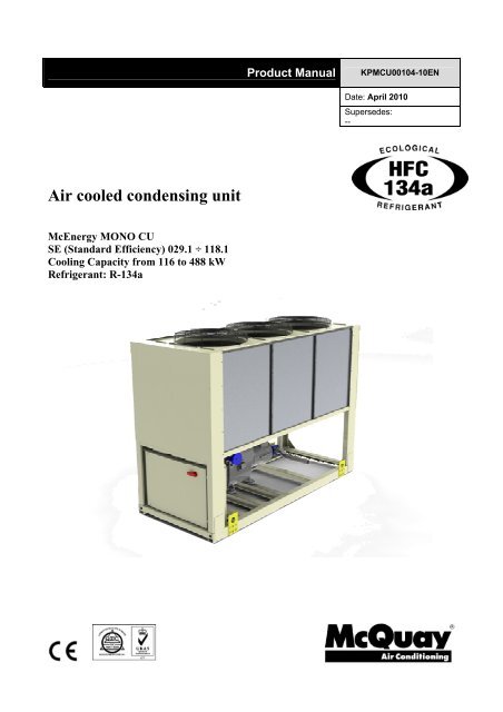
<strong>Air</strong> cooled condensing unit<br />
McEnergy MONO CU<br />
SE (Standard Efficiency) 029.1 ÷ 118.1<br />
Cooling Capacity from 116 to 488 kW<br />
Refrigerant: R-134a
Index<br />
Features and advantages ................................................................................................................................................. 3<br />
Low operating cost ......................................................................................................................................................... 3<br />
Low operating sound levels ............................................................................................................................................ 3<br />
Excellent serviceability ................................................................................................................................................... 3<br />
Proven reliability ............................................................................................................................................................. 3<br />
Infinite capacity control ................................................................................................................................................... 3<br />
Superior control logic...................................................................................................................................................... 3<br />
Code requirements – Safety and observant of laws/directives ....................................................................................... 3<br />
Certifications................................................................................................................................................................... 3<br />
Versions ......................................................................................................................................................................... 4<br />
Sound configurations...................................................................................................................................................... 4<br />
General characteristics..................................................................................................................................................... 5<br />
Cabinet and structure ..................................................................................................................................................... 5<br />
Screw compressors with integrated oil separator ........................................................................................................... 5<br />
Ecological HFC 134a refrigerant..................................................................................................................................... 5<br />
Condenser coils.............................................................................................................................................................. 5<br />
Condenser fans .............................................................................................................................................................. 5<br />
Refrigerant circuit ........................................................................................................................................................... 5<br />
Electrical control panel ................................................................................................................................................... 5<br />
Standard accessories (supplied on basic unit) ............................................................................................................... 7<br />
Options (on request)....................................................................................................................................................... 8<br />
Nomenclature .................................................................................................................................................................... 9<br />
<strong>Specification</strong>s McEnergy MONO CU SE-ST .................................................................................................................. 10<br />
<strong>Specification</strong>s McEnergy MONO CU SE-LN.................................................................................................................. 13<br />
Sound Levels................................................................................................................................................................... 16<br />
Sound pressure levels correction factor <strong>for</strong> different distances .................................................................................... 16<br />
Operating limits............................................................................................................................................................... 17<br />
Standard ratings.............................................................................................................................................................. 18<br />
Total Heat Recovery - Ratings ..................................................................................................................................... 22<br />
Partial Heat Recovery – Ratings................................................................................................................................... 22<br />
Partial Heat Recovery Pressure Drops......................................................................................................................... 23<br />
Total and Partial Heat Recovery Pressure Drops......................................................................................................... 23<br />
Dimensions...................................................................................................................................................................... 24<br />
Installation notes............................................................................................................................................................. 26<br />
Warning ........................................................................................................................................................................ 26<br />
Handling ....................................................................................................................................................................... 26<br />
Location........................................................................................................................................................................ 26<br />
Space requirements ..................................................................................................................................................... 26<br />
Acoustic protection ....................................................................................................................................................... 29<br />
Storage......................................................................................................................................................................... 29<br />
<strong>Technical</strong> <strong>Specification</strong> <strong>for</strong> <strong>Air</strong> <strong>Cooled</strong> <strong>Condensing</strong> <strong>Unit</strong>............................................................................................ 30<br />
GENERAL .................................................................................................................................................................... 30<br />
REFRIGERANT............................................................................................................................................................ 30<br />
PERFORMANCE.......................................................................................................................................................... 30<br />
UNIT DESCRIPTION.................................................................................................................................................... 30<br />
SOUND LEVEL AND VIBRATIONS ............................................................................................................................. 30<br />
DIMENSIONS............................................................................................................................................................... 30<br />
CONDENSING UNIT COMPONENTS ......................................................................................................................... 31<br />
KPMCU00104-10EN - page 2/36
Features and advantages<br />
Low operating cost<br />
McEnergy MONO CU is the result of careful design, aimed to optimizing the energy efficiency of the condensing units,<br />
with the objective of bringing down operating costs and improving installation profitability, effectiveness and economical<br />
management.<br />
The McEnergy MONO CU condensing units use the new very high efficiency single rotor screw compressor design, large<br />
condenser coil surface area <strong>for</strong> maximum heat transfer and low discharge pressure, and advanced technology<br />
condenser fans.<br />
Low operating sound levels<br />
Very low sound levels both at full load and part load conditions are achieved by the latest compressor design and by a<br />
unique new fan that moves large volume of air at exceptionally low sound levels and by the virtually vibration-free<br />
operation.<br />
Excellent serviceability<br />
Field serviceability has not been sacrificed to meet design per<strong>for</strong>mance objectives. The compressor is equipped with<br />
discharge, liquid and suction shut off valves. The compressor and serviceable components such as filter-driers are<br />
located on the outside edges of the base allowing easy access. The shaped of the coil allows easy access <strong>for</strong> inspection<br />
and service. The MicroTech III controller gives detailed in<strong>for</strong>mation on the causes of an alarm or fault.<br />
Proven reliability<br />
Extensive quality control checks during testing and prior shipment guarantee the delivery of a state of the art product.<br />
Infinite capacity control<br />
Cooling capacity control is infinitely variable by means of a single screw compressor controlled by microprocessor<br />
system. Each unit has infinitely variable capacity control from 100% down to 25%. This modulation allows the<br />
compressor capacity to exactly match the required cooling load.<br />
In the case a compressor with load step control is used, the compressor capacity, at partial loads, will be too high or too<br />
low compared to the building cooling load. The result is an increase in unit energy costs, particularly at the part-load<br />
conditions at which the unit operates most of the time.<br />
The McEnergy MONO CU condensing units with stepless regulation offer benefits that the units with step regulation are<br />
unable to match. Only a condensing unit with step-less regulation, is able to follow the system cooling demand at any<br />
time and to deliver chilled liquid or air at set-point.<br />
Superior control logic<br />
The new MicroTech III controller provides an easy to use control. The control logic is designed to guarantee a stable<br />
operation, to provide maximum efficiency, to continue operation in unusual operating conditions and to provide a history<br />
of unit operation. One of the greatest benefits is the easy interface with LonWorks, Bacnet, Ethernet TCP/IP or Modbus<br />
communications.<br />
Code requirements – Safety and observant of laws/directives<br />
All McEnergy MONO CU units are designed and manufactured in accordance with applicable selections of the following:<br />
Construction of pressure vessel 97/23/EC (PED)<br />
Machinery Directive<br />
2006/42/EC<br />
Low Voltage<br />
2006/95/EC<br />
Electromagnetic Compatibility<br />
2004/108/EC<br />
Electrical & Safety codes EN 60204–1 / EN 60335-2-40<br />
Manufacturing Quality Stds UNI – EN ISO 9001:2004<br />
Certifications<br />
All units manufactured by <strong>McQuay</strong> are CE marked, complying with European directives in <strong>for</strong>ce, concerning<br />
manufacturing and safety. On request units can be produced complying with laws in <strong>for</strong>ce in non European countries<br />
(ASME, GOST, etc.), and with other applications, such as naval (RINA, etc.).<br />
KPMCU00104-10EN - page 3/36
Versions<br />
McEnergy MONO CU is available in standard Efficiency Versions:<br />
SE: Standard Efficiency<br />
10 sizes to cover a range from 116 up to 488 kW with an EER up to 3.30 (data referred to<br />
Standard Sound configuration)<br />
The EER (Energy Efficiency Ratio) is the ratio of the Cooling Capacity to the Power Input of the<br />
unit. The Power Input includes: the power input <strong>for</strong> operation of the compressor and fans, the<br />
power input of all control and safety devices.<br />
Sound configurations<br />
McEnergy MONO CU is available in two different sound level configurations:<br />
ST: Standard Noise<br />
Condenser fan rotating at 920 rpm, rubber antivibration under compressor<br />
LN: Low Noise<br />
Condenser fan rotating at 715 rpm, rubber antivibration under compressor, compressor sound<br />
enclosure.<br />
KPMCU00104-10EN - page 4/36
General characteristics<br />
Cabinet and structure<br />
The cabinet is made of galvanized steel sheet and painted to provide a high resistance to corrosion. Colour Ivory White<br />
(Munsell code 5Y7.5/1) (±RAL7044).The base frame has eye-hook <strong>for</strong> lifting the unit with ropes <strong>for</strong> an easy installation.<br />
The weight is uni<strong>for</strong>mly distributed along the profiles of the base and this facilitates the arrangement of the unit.<br />
Screw compressors with integrated oil separator<br />
From size SE 029.1 ST to size SE 061.1 ST and from size SE 029.1 LN SE 061.1 LN<br />
The compressor is semi-hermetic, single-screw type with one gate-rotor (made of carbon impregnated engineered<br />
composite material). The compressor has one slide managed by the unit microprocessor <strong>for</strong> infinitely modulating the<br />
capacity between 100% to 25%. An integrated high efficiency oil separator maximises the oil separation. Standard Start<br />
is Wye-delta (Y-Δ) type.<br />
From size SE 073.1 ST to size SE 118.1 ST and from size SE 073.1 LN SE 118.1 LN<br />
The compressor is semi-hermetic, single-screw type with gate-rotor (with the latest high-strength fibre rein<strong>for</strong>ced star<br />
material). The compressor has an asymmetric slide regulation managed by the unit controller <strong>for</strong> infinitely modulating<br />
capacity between 100% to 25%. An integrated high efficiency oil separator maximizes the oil separation. Standard Start<br />
is Wye-delta (Y-Δ) type.<br />
Ecological HFC 134a refrigerant<br />
The compressors have been designed to operate with R-134a, ecological refrigerant with very low ODP (Ozone<br />
Depletion Potential) and GWP (Global Warming Potential) that means low TEWI (Total Equivalent Warming Impact).<br />
Condenser coils<br />
The condenser is manufactured with internally enhanced seamless copper tubes arranged in a staggered row pattern<br />
and mechanically expanded into lanced and rippled aluminium condenser fins with full fin collars. An integral sub-cooler<br />
circuit provides sub-cooling to effectively eliminate liquid flashing and increase the cooling capacity without increasing the<br />
power input.<br />
Condenser fans<br />
The condenser fans are propeller type with high efficiency design blades to maximize per<strong>for</strong>mances. The material of the<br />
blades is glass rein<strong>for</strong>ced resin and each fan is protected by a guard. Fan motors are protected by circuit breakers<br />
installed inside the electrical panel as a standard. The motors are IP54.<br />
Refrigerant circuit<br />
Each unit has 1 refrigerant circuit and includes:<br />
• Compressor with integrated oil separator<br />
• <strong>Air</strong> <strong>Cooled</strong> Condenser<br />
• Discharge line shut off valve<br />
• Liquid line shut off valve<br />
• Suction line shut off valve<br />
• Sight glass with moisture indicator<br />
• Filter drier<br />
• Charging valves<br />
• High pressure switch<br />
• High and low pressure transducers<br />
Electrical control panel<br />
Power and control are located in the main panel that is manufactured to ensure protection against all weather conditions.<br />
The electrical panel is IP54 and (when opening the doors) internally protected with plexiglas panel against possible<br />
accidental contact with electrical components (IP20). The main panel is fitted with a main switch interlocked door.<br />
Power Section<br />
The power section includes compressors fuses, fan circuit breaker, fan contactors and control circuit trans<strong>for</strong>mer.<br />
MicroTech III controller<br />
MicroTech III controller is installed as standard; it can be used to modify unit set-points and check control<br />
parameters. A built-in display shows condensing unit operating status plus temperatures and pressures of liquid or<br />
air, refrigerant and air, programmable values, set-points. A sophisticated software with predictive logic, selects the<br />
KPMCU00104-10EN - page 5/36
most energy efficient combination of compressor, condenser fans to keep stable operating conditions to maximise<br />
condensing unit energy efficiency and reliability.<br />
MicroTech III is able to protect critical components based on external signs from its system (such as motor<br />
temperatures, refrigerant gas and oil pressures, correct phase sequence, pressure switches and evaporator). The<br />
input coming from the high pressure switch cuts all digital output from the controller in less than 50ms, this is an<br />
additional security <strong>for</strong> the equipment.<br />
Fast program cycle (200ms) <strong>for</strong> a precise monitoring of the system. Floating point calculations supported <strong>for</strong><br />
increased accuracy in P/T conversions.<br />
Control section - main features<br />
• Management of the compressor stepless capacity and fans modulation.<br />
• <strong>Condensing</strong> unit enabled to work in partial failure condition.<br />
• Full routine operation at condition of:<br />
- high ambient temperature value<br />
- high thermal load<br />
- high evaporator entering liquid or air temperature (start-up)<br />
• Display of liquid or air entering/leaving temperature.<br />
• Display of Outdoor Ambient Temperature.<br />
• Display of condensing-evaporating temperature and pressure, suction and discharge superheat <strong>for</strong> the<br />
circuit.<br />
• Leaving liquid or air evaporator temperature regulation. Temperature tolerance = 0,1°C.<br />
• Compressor hours counter.<br />
• Display of Status Safety Devices.<br />
• Number of starts and compressor working hours.<br />
• Optimized management of compressor load.<br />
• Fan management according to condensing pressure.<br />
• Re-start in case of power failure (automatic / manual).<br />
• Soft Load (optimized management of the compressors load during the start-up).<br />
• Start at high evaporator liquid or air temperature.<br />
• Return Reset (Set Point Reset based on return of liquid or air temperature of evaporating section).<br />
• OAT (Outside Ambient temperature) Reset.<br />
• Set point Reset (optional).<br />
• Application and system upgrade with commercial SD cards.<br />
• Ethernet port <strong>for</strong> remote or local servicing using standard web browsers.<br />
• Two different sets of default parameters could be stored <strong>for</strong> easy restore.<br />
Safety device / logic <strong>for</strong> each refrigerant circuit<br />
• High pressure (pressure switch).<br />
• High pressure (transducer).<br />
• Low pressure (transducer).<br />
• Fans circuit breaker.<br />
• High compressor discharge temperature.<br />
• High motor winding temperature.<br />
• Phase Monitor.<br />
• Low pressure ratio.<br />
• High oil pressure drop.<br />
• Low oil pressure.<br />
• No pressure change at start.<br />
KPMCU00104-10EN - page 6/36
System security<br />
• Phase monitor.<br />
• Low Ambient temperature lock-out.<br />
• Freeze protection.<br />
Regulation type<br />
Proportional + integral + derivative regulation on the leaving water evaporator output probe.<br />
<strong>Condensing</strong> pressure<br />
<strong>Condensing</strong> pressure can be controlled in according to the entering air temperature to the condenser coil. The<br />
fans can be managed either with steps, or with a 0/10 V modulating signal or with a mixed 0/10V + Steps<br />
strategy to cover all possible operational conditions.<br />
MicroTech III<br />
MicroTech III built-in terminal has the following features.<br />
• 164x44 dots liquid crystal display with white back lighting. Supports Unicode fonts <strong>for</strong> multi-lingual.<br />
• Key-pad consisting of 3 keys.<br />
• Push’n’Roll control <strong>for</strong> an increased usability.<br />
• Memory to protect the data.<br />
• General faults alarm relays.<br />
• Password access to modify the setting.<br />
• Application security to prevent application tampering or hardware usability with third party applications.<br />
• Service report displaying all running hours and general conditions.<br />
• Alarm history memory to allow an easy fault analysis.<br />
Supervising systems (on request)<br />
MicroTech III remote control<br />
MicroTech III is able to communicate to BMS (Building Management System) based on the most common<br />
protocols as:<br />
• ModbusRTU<br />
• LonWorks, now also based on the international 8040 Standard Chiller Profile and LonMark Technology<br />
• BacNet BTP certifief over IP and MS/TP (class 4) (Native)<br />
• Ethernet TCP/IP.<br />
Standard accessories (supplied on basic unit)<br />
Wye-Delta Compressors starter (Y-Δ) – For low inrush current and reduced starting torque.<br />
Double set-point – Dual leaving liquid or air temperature set-points.<br />
Fans circuit breakers thermal overload relays – Safety devices against fan motor overloading in addition to the<br />
normal protection envisaged by the electrical windings.<br />
Phase monitor – The phase monitor controls that phases sequence is correct and controls phase loss.<br />
Discharge line shut off valves – Installed on the discharge port of the compressor to facilitate maintenance operation.<br />
Suction line shut off valve – Installed on the suction port of the compressor to facilitate maintenance operation.<br />
Ambient outside temperature sensor and set-point reset<br />
Hour run meter<br />
General fault contactor – Alarm relay.<br />
Set-point reset – The leaving liquid or air temperature set-point can be overwritten with the following options: 4-20mA<br />
from external source (by user); outside ambient temperature; evaporator liquid or air temperature Δt.<br />
Demand limit – User can limit the load of the unit by 4-20mA signal or by network system<br />
KPMCU00104-10EN - page 7/36
Alarm from external device – Microprocessor is able to receive an alarm signal from an external device (pump etc…).<br />
User can decide if this alarm signal will stop or not the unit.<br />
Fans circuit breakers – Safety device against motor overloading and short circuit<br />
Main switch interlock door<br />
Options (on request)<br />
Total heat recovery – Provided with plate to plate heat exchangers to produce hot water.<br />
Partial heat recovery – Plate to plate heat exchangers installed between the compressor discharge and the condenser<br />
coil, allowing to produce hot water.<br />
Soft starter – Electronic starting device to reduce the mechanical stress during compressor start-up.<br />
Compressor thermal overload relays – Safety devices against compressor motor overloading. This device together<br />
with internal motor protection (standard) guarantee the best safety system <strong>for</strong> compressor motor.<br />
Under/Over Voltage – This device control the voltage value of power supply and stop the chiller if the value exceeds the<br />
allowed operating limits.<br />
Energy Meter – This device allows to measure the energy absorbed by the condensing unit during its life. It is installed<br />
inside the control box mounted on a DIN rail and show on a digital display: Line-to-Line Voltage, Phase and Average<br />
Current, Active and Reactive Power, Active Energy, Frequency.<br />
Capacitors <strong>for</strong> power factor correction – To increase the operating power factor of the unit at nominal operating<br />
conditions. The capacitors are “dry” self-regenerating type with over pressure disconnectiong safety device insulated with<br />
a no toxic dielectric mix with no PCB or PCT.<br />
Current limit – To limit maximum absorbed current of the unit whenever is required<br />
Fan speed regulation – To control the fan speed revolution <strong>for</strong> smooth operating control of the unit during low ambient<br />
temperature operation. This option improves also the sound level of the unit.<br />
With “Fan speed regulation” option, by different microprocessor setting, it is also possible to set the “Fan Silent Mode”<br />
configuration. It means that the microprocessor clock switches the fan at low speed according to the client setting (i.e.<br />
Night & Day), providing that the ambient temperature/condensing pressure is allowing the speed change.<br />
It allows a perfect condensing control down to –10°C.<br />
Speedtrol – Continuous fan speed modulation on the first fan of the circuit. It allows the unit working with air temperature<br />
down to –18°C.<br />
Condenser coil guards<br />
Cu-Cu condensing coils – To give better protection against corrosion in aggressive environments.<br />
Cu-Cu-Sn condensing coils – To give better protection against corrosion in aggressive and in salty air environments.<br />
Alucoat condensing coils – Fins are protected by a special acrylic paint with a high resistance to corrosion.<br />
High pressure side manameter<br />
Kit container<br />
Rubber type anti vibration mounts – Supplied separately, these are positioned under the base of the unit during<br />
installation to reduce vibrations.<br />
Spring type anti vibration mounts – Supplied separately, these are positioned under the base of the unit during<br />
installation. Ideal <strong>for</strong> dampening vibrations <strong>for</strong> installation on roofs and metallic structures.<br />
Double pressure relief valve with diverter<br />
Compressors circuit breakers<br />
KPMCU00104-10EN - page 8/36
Nomenclature<br />
McEnergy Mono CU -A SE 029 .1 ST<br />
Machine type<br />
McEnergy Mono CU<br />
= <strong>Air</strong> <strong>Cooled</strong> <strong>Condensing</strong> <strong>Unit</strong><br />
Model series<br />
Letter A,B,…: major modification<br />
Efficiency level<br />
SE<br />
= Standard Seasonal Efficiency<br />
<strong>Unit</strong> size<br />
029 ÷ 118<br />
Always 3-digit code<br />
Number of compressors<br />
1<br />
Noise configuration<br />
ST<br />
LN<br />
= Standard Noise<br />
= Low Noise<br />
KPMCU00104-10EN - page 9/36
<strong>Specification</strong>s McEnergy MONO CU SE-ST<br />
TECHNICAL SPECIFICATIONS Version SE - ST 029.1 034.1 039.1 046.1 052.1<br />
Capacity (1) Cooling<br />
kW 121 144 165 196 219<br />
Capacity control<br />
Type<br />
---<br />
Stepless<br />
Minimum capacity<br />
% 25 25 25 25 25<br />
<strong>Unit</strong> power input (1) Cooling<br />
kW 41.8 51.0 57.4 65.2 73.7<br />
EER (1)<br />
--- 2.90 2.83 2.87 3.00 2.97<br />
Casing<br />
Dimensions<br />
Weight<br />
Piping connections<br />
Safety devices<br />
Notes (1)<br />
Colour<br />
Material<br />
<strong>Unit</strong><br />
<strong>Unit</strong><br />
Operating Weight<br />
<strong>Air</strong> heat exchanger Type<br />
Type<br />
Drive<br />
---<br />
---<br />
---<br />
Diameter<br />
Fan<br />
Nominal air flow<br />
Compressor<br />
Sound level<br />
Refrigerant circuit<br />
Model<br />
Type<br />
Oil charge<br />
Quantity<br />
Sound Power<br />
Sound Pressure (2)<br />
Refrigerant type<br />
Refrigerant charge (3)<br />
N. of circuits<br />
Suction<br />
Liquid<br />
High discharge pressure (pressure switch)<br />
High discharge pressure (pressure transducer)<br />
Low suction pressure (pressure transducer)<br />
Compressor motor protection<br />
High discharge temperature<br />
Low oil pressure<br />
Low pressure ratio<br />
High oil filter pressure drop<br />
Phase monitor<br />
---<br />
---<br />
Ivory White<br />
Galvanized and painted steel sheet<br />
Height mm 2273 2273 2273 2273 2273<br />
Width mm 1292 1292 1292 1292 1292<br />
Length mm 2165 2165 3065 3065 3965<br />
kg 1584 1584 1741 1741 1936<br />
kg 1617 1617 1781 1781 1981<br />
High efficiency fin and tube type<br />
with integral subcooler<br />
Direct propeller type<br />
DOL<br />
mm 800 800 800 800 800<br />
l/s 10922 10575 16383 15863 21844<br />
Quantity No. 2 2 3 3 4<br />
Speed rpm 920 920 920 920 920<br />
Motor input kW 1.75 1.75 1.75 1.75 1.75<br />
---<br />
Semi-hermetic<br />
single screw compressor<br />
l 13 13 13 13 13<br />
No. 1 1 1 1 1<br />
Cooling dB(A) 91.5 91.5 92.3 92.3 93.0<br />
Cooling dB(A) 73.5 73.5 73.7 73.7 73.9<br />
--- R-134a R-134a R-134a R-134a R-134a<br />
kg. 17 20 22 27 29<br />
No. 1 1 1 1 1<br />
mm 76 76 76 76 76<br />
mm 28 28 28 28 28<br />
Cooling capacity, unit power input in cooling and EER are based on the following conditions: SST 7°C; ambient 35°C, unit at<br />
full load operation.<br />
Notes (2)<br />
Notes (3)<br />
The values are according to ISO 3744 and are referred to: SST 7°C, ambient 35°C, full load operation.<br />
Refrigerant charge is <strong>for</strong> the unit only; doesn't include external suction and liquid line. <strong>Unit</strong>s are shipped without refrigerant<br />
charge; holding charge nitrogen 0.5 bar<br />
KPMCU00104-10EN - page 10/36
TECHNICAL SPECIFICATIONS Version SE - ST 061.1 073.1 087.1 102.1 118.1<br />
Capacity (1) Cooling<br />
kW 252 306 370 435 488<br />
Capacity control<br />
Type<br />
---<br />
Stepless<br />
Minimum capacity<br />
% 25 25 25 25 25<br />
<strong>Unit</strong> power input (1) Cooling<br />
kW 76.6 92.8 122 147 161<br />
EER (1)<br />
--- 3.28 3.30 3.04 2.96 3.03<br />
Casing<br />
Colour<br />
---<br />
Ivory White<br />
Material<br />
---<br />
Galvanized and painted steel sheet<br />
Dimensions<br />
Weight<br />
<strong>Air</strong> heat exchanger Type<br />
---<br />
Fan<br />
Compressor<br />
Sound level<br />
Refrigerant circuit<br />
Piping connections<br />
Safety devices<br />
Notes (1)<br />
<strong>Unit</strong><br />
<strong>Unit</strong><br />
Operating Weight<br />
Type<br />
Drive<br />
Diameter<br />
Nominal air flow<br />
Model<br />
Type<br />
Oil charge<br />
Quantity<br />
Sound Power<br />
Sound Pressure (2)<br />
Refrigerant type<br />
Refrigerant charge (3)<br />
N. of circuits<br />
Suction<br />
Liquid<br />
High discharge pressure (pressure switch)<br />
High discharge pressure (pressure transducer)<br />
Low suction pressure (pressure transducer)<br />
Compressor motor protection<br />
High discharge temperature<br />
Low oil pressure<br />
Low pressure ratio<br />
High oil filter pressure drop<br />
Phase monitor<br />
Height mm 2273 2223 2223 2223 2223<br />
Width mm 1292 2236 2236 2236 2236<br />
Length mm 3965 3070 3070 3070 3070<br />
kg 1936 2679 2679 2679 2679<br />
kg 1981 2756 2756 2756 2756<br />
High efficiency fin and tube type<br />
with integral subcooler<br />
---<br />
---<br />
mm 800 800<br />
Direct propeller type<br />
DOL<br />
800 800 800<br />
l/s 21150 32767 32767 31725 31725<br />
Quantity No. 4 6 6 6 6<br />
Speed rpm 920 920 920 920 920<br />
Motor input kW 1.75 1.75 1.75 1.75 1.75<br />
---<br />
Semi-hermetic<br />
single screw compressor<br />
l 13 16 19 19 19<br />
No. 1 1 1 1 1<br />
Cooling dB(A) 94.2 94.2 94.5 94.5 95.2<br />
Cooling dB(A) 75.1 75.0 75.3 75.3 76.0<br />
--- R-134a R-134a R-134a R-134a R-134a<br />
kg. 32 45 45 54 58<br />
No. 1 1 1 1 1<br />
mm 76 76 139.7 139.7 139.7<br />
mm 28 35 35 35 35<br />
Cooling capacity, unit power input in cooling and EER are based on the following conditions: SST 7°C; ambient 35°C, unit at<br />
full load operation.<br />
Notes (2)<br />
Notes (3)<br />
The values are according to ISO 3744 and are referred to: SST 7°C, ambient 35°C, full load operation.<br />
Refrigerant charge is <strong>for</strong> the unit only; doesn't include external suction and liquid line. <strong>Unit</strong>s are shipped without refrigerant<br />
charge; holding charge nitrogen 0.5 bar<br />
KPMCU00104-10EN - page 11/36
ELECTRICAL SPECIFICATIONS Version SE - ST 029.1 034.1 039.1 046.1 052.1<br />
Power Supply<br />
<strong>Unit</strong><br />
--- 3 3 3 3 3<br />
Hz 50 50 50 50 50<br />
V 400 400 400 400 400<br />
Minimum % -10% -10% -10% -10% -10%<br />
Maximum % +10% +10% +10% +10% +10%<br />
A 159 159 207 207 304<br />
A 72 87 98 110 127<br />
A 88 104 119 133 161<br />
A 97 114 131 146 177<br />
Maximum current <strong>for</strong> wires sizing<br />
Fans Nominal running current in cooling<br />
A 8 8 12 12 16<br />
Compressor<br />
Phase<br />
Frequency<br />
Voltage<br />
Voltage Tolerance<br />
Maximum starting current<br />
Nominal running current cooling<br />
Maximum running current<br />
Phase<br />
Voltage<br />
Voltage Tolerance<br />
No. 3 3 3 3 3<br />
V 400 400 400 400 400<br />
Minimum % -10% -10% -10% -10% -10%<br />
Maximum % +10% +10% +10% +10% +10%<br />
A 80 96 107 121 145<br />
---<br />
Maximum running current<br />
Starting method Wye – Delta type (Y – Δ)<br />
ELECTRICAL SPECIFICATIONS Version SE - ST 061.1 073.1 087.1 102.1 118.1<br />
Power Supply<br />
<strong>Unit</strong><br />
--- 3 3 3 3 3<br />
Hz 50 50 50 50 50<br />
V 400 400 400 400 400<br />
Minimum % -10% -10% -10% -10% -10%<br />
Maximum % +10% +10% +10% +10% +10%<br />
A 304 354 434 434 434<br />
A 131 156 203 243 265<br />
A 161 195 248 288 288<br />
A 177 215 273 317 317<br />
Maximum current <strong>for</strong> wires sizing<br />
Fans Nominal running current in cooling<br />
A 16 24 24 24 24<br />
Compressor<br />
Phase<br />
Frequency<br />
Voltage<br />
Voltage Tolerance<br />
Maximum starting current<br />
Nominal running current cooling<br />
Maximum running current<br />
Phase<br />
Voltage<br />
Voltage Tolerance<br />
No. 3 3 3 3 3<br />
V 400 400 400 400 400<br />
Minimum % -10% -10% -10% -10% -10%<br />
Maximum % +10% +10% +10% +10% +10%<br />
A 145 171 410 264 264<br />
---<br />
Maximum running current<br />
Starting method Wye – Delta type (Y – Δ)<br />
Allowed voltage tolerance ± 10%. Voltage unbalance between phases must be within ± 3%.<br />
Maximum starting current: starting current of biggest compressor + fans current<br />
Notes<br />
Nominal current in cooling mode is referred to the following conditions: SST 7°C; ambient 35°C; compressor + fans current.<br />
Maximum running current is based on max compressor absorbed current in its envelope and max fans absorbed current<br />
Maximum unit current <strong>for</strong> wires sizing is based on minimum allowed voltage<br />
Maximum current <strong>for</strong> wires sizing: (compressors full load ampere + fans current) x 1,1.<br />
KPMCU00104-10EN - page 12/36
<strong>Specification</strong>s McEnergy MONO CU SE-LN<br />
TECHNICAL SPECIFICATIONS Version SE - LN 029.1 034.1 039.1 046.1 052.1<br />
Capacity (1) Cooling<br />
kW 116 137 159 187 209<br />
Capacity control<br />
Type<br />
---<br />
Stepless<br />
Minimum capacity<br />
% 25 25 25 25 25<br />
<strong>Unit</strong> power input (1) Cooling<br />
kW 42.3 52.5 57.6 66.3 73.9<br />
EER (1)<br />
--- 2.74 2.61 2.75 2.82 2.83<br />
Casing<br />
Dimensions<br />
Weight<br />
<strong>Air</strong> heat exchanger Type<br />
---<br />
Fan<br />
Compressor<br />
Sound level<br />
Refrigerant circuit<br />
Piping connections<br />
Safety devices<br />
Notes (1)<br />
Colour<br />
Material<br />
<strong>Unit</strong><br />
<strong>Unit</strong><br />
Operating Weight<br />
Type<br />
Drive<br />
Diameter<br />
Nominal air flow<br />
Model<br />
Type<br />
Oil charge<br />
Quantity<br />
Sound Power<br />
Sound Pressure (2)<br />
Refrigerant type<br />
Refrigerant charge (3)<br />
N. of circuits<br />
Suction<br />
Liquid<br />
High discharge pressure (pressure switch)<br />
High discharge pressure (pressure transducer)<br />
Low suction pressure (pressure transducer)<br />
Compressor motor protection<br />
High discharge temperature<br />
Low oil pressure<br />
Low pressure ratio<br />
High oil filter pressure drop<br />
Phase monitor<br />
---<br />
---<br />
Height mm 2273 2273 2273 2273 2273<br />
Width mm 1292 1292 1292 1292 1292<br />
Length mm 2165 2165 3065 3065 3965<br />
kg 1684 1684 1841 1841 2036<br />
kg 1717 1717 1881 1881 2081<br />
---<br />
---<br />
Ivory White<br />
Galvanized and painted steel sheet<br />
High efficiency fin and tube type<br />
with integral subcooler<br />
Direct propeller type<br />
DOL<br />
mm 800 800 800 800 800<br />
l/s 8372 8144 12558 12217 16744<br />
Quantity No. 2 2 3 3 4<br />
Speed rpm 715 715 715 715 715<br />
Motor input kW 0.78 0.78 0.78 0.78 0.78<br />
---<br />
Semi-hermetic<br />
single screw compressor<br />
l 13 13 13 13 13<br />
No. 1 1 1 1 1<br />
Cooling dB(A) 89.0 89.0 89.8 89.8 90.5<br />
Cooling dB(A) 71.0 71.0 71.2 71.2 71.4<br />
--- R-134a R-134a R-134a R-134a R-134a<br />
kg. 17 20 22 27 29<br />
No. 1 1 1 1 1<br />
mm 76 76 76 76 76<br />
mm 28 28 28 28 28<br />
Cooling capacity, unit power input in cooling and EER are based on the following conditions: SST 7°C; ambient 35°C, unit at<br />
full load operation.<br />
Notes (2)<br />
Notes (3)<br />
The values are according to ISO 3744 and are referred to: SST 7°C, ambient 35°C, full load operation.<br />
Refrigerant charge is <strong>for</strong> the unit only; doesn't include external suction and liquid line. <strong>Unit</strong>s are shipped without refrigerant<br />
charge; holding charge nitrogen 0.5 bar<br />
KPMCU00104-10EN - page 13/36
TECHNICAL SPECIFICATIONS Version SE - LN 061.1 073.1 087.1 102.1 118.1<br />
Capacity (1) Cooling<br />
kW 243 295 352 409 462<br />
Capacity control<br />
Type<br />
---<br />
Stepless<br />
Minimum capacity<br />
% 25 25 25 25 25<br />
<strong>Unit</strong> power input (1) Cooling<br />
kW 78.2 91.5 122.4 150.1 167.2<br />
EER (1)<br />
--- 3.11 3.23 2.88 2.73 2.76<br />
Casing<br />
Colour<br />
---<br />
Ivory White<br />
Material<br />
---<br />
Galvanized and painted steel sheet<br />
Dimensions<br />
Weight<br />
<strong>Air</strong> heat exchanger Type<br />
---<br />
Fan<br />
Compressor<br />
Sound level<br />
Refrigerant circuit<br />
Piping connections<br />
Safety devices<br />
Notes (1)<br />
<strong>Unit</strong><br />
<strong>Unit</strong><br />
Operating Weight<br />
Type<br />
Drive<br />
Diameter<br />
Nominal air flow<br />
Model<br />
Type<br />
Oil charge<br />
Quantity<br />
Sound Power<br />
Sound Pressure (2)<br />
Refrigerant type<br />
Refrigerant charge (3)<br />
N. of circuits<br />
Suction<br />
Liquid<br />
Height mm 2273 2223 2223 2223 2223<br />
Width mm 1292 2236 2236 2236 2236<br />
Length mm 3965 3070 3070 3070 3070<br />
kg 2036 2789 2789 2789 2789<br />
kg 2081 2886 2886 2886 2886<br />
High efficiency fin and tube type<br />
with integral subcooler<br />
---<br />
---<br />
mm 800 800<br />
Direct propeller type<br />
DOL<br />
800 800 800<br />
l/s 16289 25117 25117 24433 24433<br />
Quantity No. 4 6 6 6 6<br />
Speed rpm 715 715 715 715 715<br />
Motor input kW 0.78 0.78 0.78 0.78 0.78<br />
---<br />
Semi-hermetic<br />
single screw compressor<br />
l 13 16 19 19 19<br />
No. 1 1 1 1 1<br />
Cooling dB(A) 91.7 91.7 92.0 92.0 92.7<br />
Cooling dB(A) 72.6 72.5 72.8 72.8 73.5<br />
--- R-134a R-134a R-134a R-134a R-134a<br />
kg. 32 45 45 54 58<br />
No. 1 1 1 1 1<br />
mm 76 76 139.7 139.7 139.7<br />
mm 28 35 35 35 35<br />
High discharge pressure (pressure switch)<br />
High discharge pressure (pressure transducer)<br />
Low suction pressure (pressure transducer)<br />
Compressor motor protection<br />
High discharge temperature<br />
Low oil pressure<br />
Low pressure ratio<br />
High oil filter pressure drop<br />
Phase monitor<br />
Cooling capacity, unit power input in cooling and EER are based on the following conditions: SST 7°C; ambient 35°C, unit at<br />
full load operation.<br />
Notes (2)<br />
Notes (3)<br />
The values are according to ISO 3744 and are referred to: SST 7°C, ambient 35°C, full load operation.<br />
Refrigerant charge is <strong>for</strong> the unit only; doesn't include external suction and liquid line. <strong>Unit</strong>s are shipped without refrigerant<br />
charge; holding charge nitrogen 0.5 bar<br />
KPMCU00104-10EN - page 14/36
ELECTRICAL SPECIFICATIONS Version SE - LN 029.1 034.1 039.1 046.1 052.1<br />
Power Supply<br />
<strong>Unit</strong><br />
Phase<br />
Frequency<br />
Voltage<br />
Voltage Tolerance<br />
Maximum starting current<br />
Nominal running current cooling<br />
Maximum running current<br />
Maximum current <strong>for</strong> wires sizing<br />
--- 3 3 3 3 3<br />
Hz 50 50 50 50 50<br />
V 400 400 400 400 400<br />
Minimum % -10% -10% -10% -10% -10%<br />
Maximum % +10% +10% +10% +10% +10%<br />
A 156 156 203 203 298<br />
A 73 90 98 111 127<br />
A 85 101 115 129 155<br />
A 94 111 126 142 171<br />
Fans Nominal running current in cooling<br />
A 5.2 5.2 7.8 7.8 10.4<br />
Compressor<br />
Phase<br />
Voltage<br />
Voltage Tolerance<br />
No. 3 3 3 3 3<br />
V 400 400 400 400 400<br />
Minimum % -10% -10% -10% -10% -10%<br />
Maximum % +10% +10% +10% +10% +10%<br />
A 80 96 107 121 145<br />
---<br />
Maximum running current<br />
Starting method Wye – Delta type (Y – Δ)<br />
ELECTRICAL SPECIFICATIONS Version SE - LN 061.1 073.1 087.1 102.1 118.1<br />
Power Supply<br />
<strong>Unit</strong><br />
Phase<br />
Frequency<br />
Voltage<br />
Voltage Tolerance<br />
Maximum starting current<br />
Nominal running current cooling<br />
Maximum running current<br />
Maximum current <strong>for</strong> wires sizing<br />
--- 3 3 3 3 3<br />
Hz 50 50 50 50 50<br />
V 400 400 400 400 400<br />
Minimum % -10% -10% -10% -10% -10%<br />
Maximum % +10% +10% +10% +10% +10%<br />
A 298 346 426 426 426<br />
A 133 154 203 248 274<br />
A 155 187 240 280 280<br />
A 171 205 264 308 308<br />
Fans Nominal running current in cooling<br />
A 10.4 15.6 15.6 15.6 15.6<br />
Compressor<br />
Phase<br />
Voltage<br />
Voltage Tolerance<br />
No. 3 3 3 3 3<br />
V 400 400 400 400 400<br />
Minimum % -10% -10% -10% -10% -10%<br />
Maximum % +10% +10% +10% +10% +10%<br />
A 145 171 410 264 264<br />
---<br />
Maximum running current<br />
Starting method Wye – Delta type (Y – Δ)<br />
Allowed voltage tolerance ± 10%. Voltage unbalance between phases must be within ± 3%.<br />
Maximum starting current: starting current of biggest compressor + fans current<br />
Notes<br />
Nominal current in cooling mode is referred to the following conditions: SST 7°C; ambient 35°C; compressor + fans current.<br />
Maximum running current is based on max compressor absorbed current in its envelope and max fans absorbed current<br />
Maximum unit current <strong>for</strong> wires sizing is based on minimum allowed voltage<br />
Maximum current <strong>for</strong> wires sizing: (compressors full load ampere + fans current) x 1,1.<br />
KPMCU00104-10EN - page 15/36
Sound Levels<br />
McEnergy MONO CU SE-ST<br />
Sound pressure level at 1 m from the unit in semispheric free field (rif. 2 x 10 -5 Pa)<br />
Power<br />
<strong>Unit</strong> size<br />
63 Hz 125 Hz 250 Hz 500 Hz 1000 Hz 2000 Hz 4000 Hz 8000 Hz dB(A) dB(A)<br />
029.1 75.5 70.8 68.9 75.3 64.3 61.7 53.0 47.3 73.5 91.5<br />
034.1 75.5 70.8 68.9 75.3 64.3 61.7 53.0 47.3 73.5 91.5<br />
039.1 75.7 71.0 69.1 75.5 64.5 61.9 53.2 47.5 73.7 92.3<br />
046.1 75.7 71.0 69.1 75.5 64.5 61.9 53.2 47.5 73.7 92.3<br />
052.1 75.9 71.2 69.3 75.7 64.7 62.1 53.4 47.7 73.9 93.0<br />
061.1 77.1 72.4 70.5 76.9 65.9 63.3 54.6 48.9 75.1 94.2<br />
073.1 77.0 72.3 70.4 76.8 65.8 63.2 54.5 48.8 75.0 94.2<br />
087.1 77.3 72.6 70.7 77.1 66.1 63.5 54.8 49.1 75.3 94.5<br />
102.1 77.3 72.6 70.7 77.1 66.1 63.5 54.8 49.1 75.3 94.5<br />
118.1 78.0 73.3 71.4 77.8 66.8 64.2 55.5 49.8 76.0 95.2<br />
Note: The values are according to ISO 3744 and are referred to: evaporator 12/7° C, air ambient 35° C, full load operation<br />
McEnergy MONO CU SE-LN<br />
Sound pressure level at 1 m from the unit in semispheric free field (rif. 2 x 10 -5 Pa)<br />
Power<br />
<strong>Unit</strong> size<br />
63 Hz 125 Hz 250 Hz 500 Hz 1000 Hz 2000 Hz 4000 Hz 8000 Hz dB(A) dB(A)<br />
029.1 73.0 68.3 66.4 72.8 61.8 59.2 50.5 44.8 71.0 89.0<br />
034.1 73.0 68.3 66.4 72.8 61.8 59.2 50.5 44.8 71.0 89.0<br />
039.1 73.2 68.5 66.6 73.0 62.0 59.4 50.7 45.0 71.2 89.8<br />
046.1 73.2 68.5 66.6 73.0 62.0 59.4 50.7 45.0 71.2 89.8<br />
052.1 73.4 68.7 66.8 73.2 62.2 59.6 50.9 45.2 71.4 90.5<br />
061.1 74.6 69.9 68.0 74.4 63.4 60.8 52.1 46.4 72.6 91.7<br />
073.1 74.5 69.8 67.9 74.3 63.3 60.7 52.0 46.3 72.5 91.7<br />
087.1 74.8 70.1 68.2 74.6 63.6 61.0 52.3 46.6 72.8 92.0<br />
102.1 74.8 70.1 68.2 74.6 63.6 61.0 52.3 46.6 72.8 92.0<br />
118.1 75.5 70.8 68.9 75.3 64.3 61.7 53.0 47.3 73.5 92.7<br />
Note: The values are according to ISO 3744 and are referred to: evaporator 12/7° C, air ambient 35° C, full load operation<br />
Sound pressure levels correction factor <strong>for</strong> different distances<br />
McEnergy MONO CU SE-ST / LN<br />
<strong>Unit</strong> size<br />
Distance<br />
1m 5m 10m 15m 20m 25m 50m<br />
029.1 0.0 -8.8 -13.9 -17.1 -19.4 -21.2 -27.0<br />
034.1 0.0 -8.8 -13.9 -17.1 -19.4 -21.2 -27.0<br />
039.1 0.0 -8.5 -13.5 -16.6 -18.9 -20.7 -26.5<br />
046.1 0.0 -8.5 -13.5 -16.6 -18.9 -20.7 -26.5<br />
052.1 0.0 -8.2 -13.1 -16.2 -18.4 -20.3 -26.0<br />
061.1 0.0 -8.2 -13.1 -16.2 -18.4 -20.3 -26.0<br />
073.1 0.0 -8.1 -13.0 -16.1 -18.4 -20.2 -25.9<br />
087.1 0.0 -8.1 -13.0 -16.1 -18.4 -20.2 -25.9<br />
102.1 0.0 -8.1 -13.0 -16.1 -18.4 -20.2 -25.9<br />
118.1 0.0 -8.1 -13.0 -16.1 -18.4 -20.2 -25.9<br />
Note: Reduction to be applied to standard and low noise sound levels<br />
KPMCU00104-10EN - page 16/36
Operating limits<br />
McEnergy MONO SE-CU ST / LN<br />
55<br />
50<br />
45<br />
"ICE mode" operation<br />
only<br />
40<br />
35<br />
Condenser Inlet <strong>Air</strong> Temp. (°C)<br />
30<br />
25<br />
20<br />
15<br />
10<br />
5<br />
0<br />
‐5<br />
‐10<br />
‐15<br />
Frost protection required<br />
on evaporating unit<br />
Fan speed modulation required<br />
(below 18°C Condens. <strong>Air</strong> Temp. <strong>for</strong> less than 3 fans units)<br />
Fan speed modulation required<br />
(below 10°C Condens. <strong>Air</strong> Temp. <strong>for</strong> 3 or more fans units)<br />
Speedtroll required (below ‐10°C Condens. <strong>Air</strong> Temp.)<br />
‐20<br />
‐12 ‐11 ‐10 ‐9 ‐8 ‐7 ‐6 ‐5 ‐4 ‐3 ‐2 ‐1 0 1 2 3 4 5 6 7 8 9 10 11 12 13 14 15<br />
Saturated Suction Temp. (°C)<br />
Table 1 - <strong>Air</strong> heat exchanger - Altitude correction factors<br />
Elevation above sea level (m)<br />
Barometric pressure (mbar)<br />
Cooling capacity correction factor<br />
Power input correction factor<br />
0 300 600 900 1200 1500 1800<br />
1013 977 942 908 875 843 812<br />
1.000 0.993 0.986 0.979 0.973 0.967 0.960<br />
1.000 1.005 1.009 1.015 1.021 1.026 1.031<br />
- Maximum operating altitude is 2000 m above sea level<br />
- Contact factory in case the unit has to be installed at altitudes between 1000 and 2000 m above sea level<br />
KPMCU00104-10EN - page 17/36
Standard ratings<br />
McEnergy MONO CU SE-ST<br />
29<br />
34<br />
39<br />
46<br />
52<br />
Condenser Inlet <strong>Air</strong> Temperature (°C)<br />
SST (°C) 20 25 30 35<br />
40<br />
45<br />
48<br />
Cc (kW) Pi (kW) Cc (kW) Pi (kW) Cc (kW) Pi (kW) Cc (kW) Pi (kW) Cc (kW) Pi (kW) Cc (kW) Pi (kW) Cc (kW) Pi (kW)<br />
-9 80.6 25.6 76.3 27.9 71.7 30.4 66.7 33.2 61.6 36.2 56.0 39.4 52.5 41.5<br />
-7 87.0 26.3 82.5 28.7 77.8 31.2 72.7 34.0 67.3 37.1 61.6 40.3 57.9 42.4<br />
-5 93.8 27.1 89.1 29.5 84.0 32.1 78.8 34.9 73.2 38.0 67.3 41.3 63.6 43.4<br />
-3 101 28.0 95.9 30.4 90.7 33.1 85.2 35.9 79.3 39.0 73.1 42.4 69.3 44.5<br />
-1 108 29.0 103 31.4 97.5 34.1 91.8 37.0 85.7 40.1 79.3 43.5 75.3 45.6<br />
1 116 30.0 111 32.5 105 35.2 98.7 38.1 92.4 41.2 85.7 44.6 81.5 46.8<br />
3 124 31.1 118 33.6 112 36.3 106 39.3 99.2 42.4 92.2 45.8 87.2 47.6<br />
5 132 32.3 126 34.8 120 37.6 113 40.5 106 43.7 99.1 47.1 88.7 45.8<br />
7 141 33.5 135 36.1 128 38.8 121 41.8 114 45.0 106 48.5 90.3 44.2<br />
9 150 34.8 143 37.4 136 40.2 129 43.2 121 46.4 111 48.5 92.4 43.1<br />
11 160 36.2 152 38.8 145 41.6 137 44.6 129 47.9 113 47.0 93.0 41.4<br />
13 164 36.9 157 39.5 149 42.3 142 45.4 133 48.6 113 46.2 94.0 41.0<br />
-9 97.0 30.7 91.7 33.5 86.0 36.6 80.0 40.0 73.6 43.7 66.8 47.6 62.5 50.1<br />
-7 105 31.7 99.2 34.6 93.3 37.7 87.0 41.1 80.4 44.8 73.4 48.8 69.0 51.3<br />
-5 113 32.8 107 35.7 101 38.9 94.3 42.3 87.4 46.0 80.2 50.0 75.6 52.6<br />
-3 121 33.9 115 36.9 109 40.1 102 43.5 94.8 47.3 87.2 51.3 82.5 53.9<br />
-1 130 35.1 124 38.1 117 41.4 110 44.9 102 48.7 94.5 52.7 89.5 55.3<br />
1 139 36.4 132 39.4 125 42.7 118 46.3 110 50.1 102 54.2 94.8 55.3<br />
3 149 37.8 142 40.9 134 44.2 126 47.7 118 51.6 110 55.8 96.5 53.1<br />
5 159 39.3 151 42.4 143 45.7 135 49.3 127 53.2 118 57.4 98.6 51.3<br />
7 169 40.8 161 43.9 153 47.3 144 51.0 135 54.9 121 56.3 101 50.0<br />
9 180 42.4 171 45.6 163 49.0 154 52.7 144 56.7 124 54.5 102 48.0<br />
11 191 44.2 182 47.4 173 50.8 163 54.5 154 58.6 125 52.6 104 47.0<br />
13 196 45.0 187 48.3 178 51.8 168 55.5 158 59.5 126 51.6 104 46.0<br />
-9 109 35.7 103 38.9 96.8 42.3 90.3 46.0 83.5 50.1 76.1 54.6 71.5 57.5<br />
-7 117 36.7 111 40.0 105 43.4 98.4 47.2 91.3 51.3 83.6 55.9 78.8 58.9<br />
-5 126 37.9 120 41.1 114 44.6 107 48.4 99.3 52.6 91.5 57.3 86.4 60.3<br />
-3 136 39.1 130 42.3 123 45.9 115 49.7 108 54.0 99.5 58.7 94.3 61.8<br />
-1 146 40.3 139 43.6 132 47.2 125 51.1 116 55.4 108 60.2 102 63.4<br />
1 157 41.6 150 45.0 142 48.6 134 52.5 126 56.9 117 61.8 111 65.0<br />
3 168 43.0 160 46.4 152 50.0 144 54.1 135 58.5 126 63.4 120 66.7<br />
5 179 44.5 171 47.9 163 51.6 154 55.7 145 60.2 135 65.2 129 68.5<br />
7 191 46.1 183 49.5 174 53.3 165 57.4 155 62.0 145 67.0 134 67.8<br />
9 204 47.8 195 51.3 186 55.1 176 59.2 166 63.8 155 69.0 137 65.7<br />
11 217 49.6 207 53.1 197 56.9 187 61.2 177 65.8 165 71.1 138 63.4<br />
13 223 50.6 214 54.1 204 57.9 193 62.2 182 66.9 168 70.9 140 62.9<br />
-9 130 39.8 123 43.5 116 47.5 108 51.9 100 56.6 90.7 61.7 85.2 65.0<br />
-7 140 41.1 133 44.8 125 48.8 117 53.2 109 58.0 100 63.1 93.8 66.4<br />
-5 151 42.4 144 46.1 136 50.2 127 54.7 118 59.5 109 64.7 103 68.0<br />
-3 163 43.8 155 47.6 146 51.7 138 56.2 128 61.0 118 66.2 112 69.6<br />
-1 175 45.3 166 49.1 158 53.3 148 57.8 139 62.7 128 67.9 122 71.3<br />
1 187 46.9 178 50.7 169 54.9 160 59.5 149 64.4 139 69.7 132 73.1<br />
3 200 48.5 191 52.5 181 56.7 171 61.3 161 66.3 149 71.6 142 75.0<br />
5 214 50.3 204 54.3 194 58.6 183 63.2 172 68.2 161 73.6 150 75.0<br />
7 228 52.2 218 56.2 207 60.5 196 65.2 184 70.3 172 75.7 153 72.7<br />
9 243 54.2 232 58.2 221 62.6 209 67.3 197 72.4 184 77.9 155 70.2<br />
11 258 56.3 247 60.4 235 64.8 222 69.6 210 74.7 190 77.3 157 67.7<br />
13 266 57.4 254 61.5 242 65.9 229 70.7 216 75.9 192 76.1 159 67.1<br />
-9 145 45.6 137 49.7 129 54.1 120 59.0 111 64.5 99.5 70.8 91.7 75.0<br />
-7 156 46.9 148 51.1 140 55.5 131 60.5 121 66.1 109 72.4 101 76.7<br />
-5 169 48.4 160 52.5 152 57.0 142 62.0 132 67.7 119 74.2 110 78.5<br />
-3 182 49.9 173 54.1 164 58.7 154 63.7 143 69.5 129 76.0 120 80.3<br />
-1 195 51.5 186 55.8 177 60.4 166 65.5 154 71.3 140 77.9 130 82.3<br />
1 210 53.3 200 57.5 190 62.2 178 67.4 166 73.3 150 79.9 140 84.3<br />
3 224 55.1 214 59.4 204 64.1 191 69.4 178 75.3 161 82.1 150 86.5<br />
5 240 57.0 229 61.4 218 66.2 205 71.5 190 77.5 173 84.3 161 88.8<br />
7 256 59.1 245 63.5 232 68.3 219 73.7 203 79.9 184 86.7 172 91.3<br />
9 273 61.3 261 65.7 248 70.6 233 76.1 216 82.3 196 89.3 179 90.4<br />
11 291 63.6 278 68.1 263 73.1 247 78.6 229 84.9 209 92.0 182 87.5<br />
13 300 64.8 286 69.3 271 74.3 255 80.0 236 86.3 215 93.3 184 86.0<br />
Notes:<br />
Cc (cooling capacity) - Pi (unit power input) – SST (compressor saturated suction temperature)<br />
KPMCU00104-10EN - page 18/36
61<br />
73<br />
87<br />
102<br />
118<br />
Condenser Inlet <strong>Air</strong> Temperature (°C)<br />
SST (°C) 20 25 30 35<br />
40<br />
45<br />
48<br />
Cc (kW) Pi (kW) Cc (kW) Pi (kW) Cc (kW) Pi (kW) Cc (kW) Pi (kW) Cc (kW) Pi (kW) Cc (kW) Pi (kW) Cc (kW) Pi (kW)<br />
-9 162 46.7 157 51.8 152 57.0 146 62.7 138 69.1 126 76.4 118 81.2<br />
-7 173 47.8 169 53.0 164 58.3 158 64.1 149 70.6 138 78.1 129 83.0<br />
-5 185 49.0 181 54.3 177 59.7 170 65.6 161 72.3 149 79.8 140 84.8<br />
-3 198 50.3 194 55.6 190 61.2 183 67.2 173 74.0 160 81.6 151 86.7<br />
-1 210 51.7 207 57.1 203 62.7 196 68.9 186 75.8 172 83.6 162 88.7<br />
1 224 53.1 221 58.6 217 64.4 209 70.7 199 77.7 184 85.6 174 90.8<br />
3 238 54.7 235 60.3 231 66.1 223 72.5 212 79.6 196 87.7 185 93.0<br />
5 253 56.3 250 62.0 245 68.0 237 74.5 225 81.7 209 89.9 197 95.2<br />
7 268 58.1 266 63.9 260 69.9 252 76.6 239 83.9 222 92.2 205 94.9<br />
9 284 60.0 282 65.8 276 72.0 266 78.7 253 86.2 234 94.6 209 92.3<br />
11 301 62.0 298 67.9 292 74.2 281 81.1 267 88.7 248 97.2 212 89.7<br />
13 310 63.0 307 69.0 300 75.3 289 82.3 274 89.9 254 98.5 213 87.8<br />
-9 200 58.5 189 63.5 179 69 168 76.1 157 84.1 143 93.7 134 100<br />
-7 216 60.2 205 65.2 194 71 183 77.6 170 85.4 156 94.8 146 101<br />
-5 233 62.0 222 67.0 210 73 198 79.2 185 86.9 169 96.1 159 102<br />
-3 251 64.0 239 68.9 227 75 214 81.0 200 88.6 184 97.6 173 104<br />
-1 270 66.2 258 71.1 245 77 231 83.0 216 90.5 198 99.3 187 105<br />
1 291 68.5 277 73.4 263 79 249 85.2 232 92.6 214 101 202 107<br />
3 312 71.0 297 75.9 283 81 267 87.5 250 94.8 230 103 217 109<br />
5 334 73.7 318 78.5 303 84 286 90.1 268 97.3 247 106 233 111<br />
7 356 76.6 341 81.4 324 87 306 92.8 286 100 265 108 250 114<br />
9 380 79.7 363 84.4 346 90 327 95.8 306 103 283 111 267 116<br />
11 405 82.9 387 87.6 369 93 348 98.9 326 106 302 114 286 119<br />
13 418 84.6 400 89.3 380 95 359 101 337 108 311 115 288 118<br />
-9 248 74.4 234 80.0 221 86 207 91.9 192 98.4 174 106 162 110<br />
-7 268 77.1 254 82.8 240 89 225 95.1 208 102 189 109 177 114<br />
-5 289 79.9 274 85.8 259 92 243 99 225 106 205 113 192 118<br />
-3 311 82.8 295 88.9 279 95 262 102 243 109 222 117 208 122<br />
-1 334 85.9 318 92.2 301 99 282 106 262 113 239 121 224 126<br />
1 359 89.2 341 95.6 323 102 303 110 281 117 257 125 241 130<br />
3 384 92.6 365 99.2 346 106 325 114 301 121 276 130 259 135<br />
5 410 96.2 391 103 370 110 347 118 322 126 295 134 269 136<br />
7 438 100 417 107 394 114 370 122 344 130 315 139 273 133<br />
9 466 104 444 111 420 119 394 127 366 135 335 144 275 128<br />
11 496 108 472 116 446 123 419 131 389 140 339 141 281 125<br />
13 511 110 486 118 460 126 432 134 401 143 340 138 282 123<br />
-9 294 88.5 278 95.3 262 102 246 110 227 118 205 126 191 132<br />
-7 318 91.9 301 98.8 284 106 266 114 246 122 223 131 208 136<br />
-5 343 95.4 325 103 307 110 288 118 266 126 241 135 225 141<br />
-3 369 99.1 350 106 331 114 310 122 287 131 261 140 243 146<br />
-1 396 103 376 111 356 118 333 127 308 136 281 145 262 152<br />
1 425 107 404 115 382 123 358 132 331 141 301 151 282 157<br />
3 455 111 432 119 408 128 383 137 354 146 323 156 294 158<br />
5 485 116 462 124 436 133 409 142 378 152 345 162 296 153<br />
7 517 121 492 129 465 138 435 147 403 157 368 168 302 149<br />
9 551 126 523 134 495 143 463 153 429 163 370 163 306 144<br />
11 585 131 556 140 525 149 492 159 455 169 376 159 311 140<br />
13 602 134 572 143 540 152 506 162 469 173 379 157 311 137<br />
-9 325 94.5 315 103 304 112 292 121 277 131 256 143 240 151<br />
-7 349 97.9 338 107 327 116 314 125 297 136 275 148 258 156<br />
-5 374 101 362 111 351 120 337 130 318 141 294 153 277 161<br />
-3 400 105 388 115 375 124 360 134 340 146 315 158 288 162<br />
-1 427 109 414 119 401 129 384 139 363 151 335 164 293 159<br />
1 455 113 442 123 427 133 409 144 386 156 357 169 298 155<br />
3 484 118 470 128 454 138 435 150 410 162 365 168 300 149<br />
5 515 122 500 133 482 144 461 155 434 167 370 164 304 145<br />
7 546 127 530 138 511 149 488 161 459 174 372 159 309 141<br />
9 579 132 561 143 541 155 516 167 485 180 377 155 313 137<br />
11 613 138 594 149 571 161 544 173 493 178 383 152 316 133<br />
13 630 141 610 152 587 164 558 176 494 176 386 150 317 130<br />
Notes:<br />
Cc (cooling capacity) - Pi (unit power input) – SST (compressor saturated suction temperature)<br />
KPMCU00104-10EN - page 19/36
McEnergy MONO CU SE-LN<br />
29<br />
34<br />
39<br />
46<br />
52<br />
Condenser Inlet <strong>Air</strong> Temperature (°C)<br />
SST (°C) 20 25 30 35 40<br />
45<br />
48<br />
Cc (kW) Pi (kW) Cc (kW) Pi (kW) Cc (kW) Pi (kW) Cc (kW) Pi (kW) Cc (kW) Pi (kW) Cc (kW) Pi (kW) Cc (kW) Pi (kW)<br />
-9 78.7 24.9 74.3 27.3 69.6 29.9 64.6 32.7 59.3 35.8 53.7 39.1 50.2 41.2<br />
-7 84.9 25.7 80.3 28.2 75.4 30.8 70.2 33.7 64.8 36.8 58.9 40.1 55.3 42.3<br />
-5 91.4 26.6 86.6 29.1 81.5 31.8 76.1 34.7 70.5 37.8 64.4 41.2 60.6 43.4<br />
-3 98.2 27.6 93 30.1 88 32.9 82.2 35.8 76.2 39.0 70.0 42.4 66.0 44.5<br />
-1 105 28.7 100 31.2 94 34.0 88.5 37.0 82.3 40.2 75.8 43.6 69.1 43.7<br />
1 113 29.8 107 32.4 101 35.2 95.1 38.2 88.6 41.4 81.8 44.9 70.7 41.9<br />
3 120 31.1 114 33.7 108 36.5 102 39.5 95.1 42.8 88.0 46.3 72.2 40.4<br />
5 128 32.3 122 35.0 116 37.8 109 40.9 102 44.2 89.5 44.5 73.3 38.9<br />
7 136 33.7 130 36.4 123 39.2 116 42.3 109 45.6 91.3 42.9 74.7 37.7<br />
9 145 35.1 138 37.8 131 40.7 123 43.8 116 47.2 92.5 41.4 76.4 36.8<br />
11 154 36.6 146 39.4 139 42.3 131 45.4 121 47.9 94.0 40.1 76.8 35.5<br />
13 158 37.4 151 40.1 143 43.1 135 46.2 122 47.1 94.1 39.3 77.4 35.0<br />
-9 94.1 30.5 88.7 33.5 82.9 36.7 76.8 40.1 70.2 43.9 63.3 47.9 58.9 50.5<br />
-7 102 31.6 95.9 34.6 89.8 37.9 83.5 41.4 76.7 45.2 69.5 49.3 65.0 51.9<br />
-5 109 32.8 103 35.9 97 39.2 90.4 42.7 83.3 46.6 75.9 50.7 70.8 52.8<br />
-3 117 34.1 111 37.2 104 40.5 97.5 44.1 90.2 48.0 82.5 52.2 72.7 50.3<br />
-1 126 35.5 119 38.6 112 42.0 105 45.6 97.3 49.6 89.3 53.8 75.2 48.6<br />
1 134 37.0 127 40.1 120 43.5 113 47.2 105 51.2 93.6 53.3 76.3 46.4<br />
3 143 38.5 136 41.7 128 45.2 121 48.9 112 52.9 95.4 51.1 78.3 45.1<br />
5 152 40.2 145 43.4 137 46.9 129 50.7 120 54.7 97.2 49.3 79.7 43.6<br />
7 162 41.9 154 45.2 146 48.7 137 52.5 128 56.6 98.6 47.4 80.6 42.1<br />
9 172 43.7 163 47.1 155 50.6 146 54.5 131 55.0 100 45.9 82.1 41.0<br />
11 182 45.7 173 49.0 164 52.7 154 56.6 132 53.1 101 44.4 83.0 39.9<br />
13 187 46.7 178 50.1 169 53.7 159 57.6 133 52.1 102 43.9 83.2 39.3<br />
-9 106 34.4 101 37.6 94 41.1 87.8 44.9 80.8 49.1 73.3 53.8 68.6 56.8<br />
-7 115 35.5 109 38.8 102 42.4 95.5 46.2 88.3 50.5 80.4 55.3 75.6 58.4<br />
-5 124 36.8 117 40.1 111 43.7 104 47.6 96.0 52.0 88.0 56.8 82.8 60.0<br />
-3 133 38.1 126 41.4 119 45.1 112 49.1 104 53.5 95.7 58.4 90.3 61.6<br />
-1 143 39.4 136 42.8 128 46.5 121 50.6 112 55.1 104 60.1 98.2 63.4<br />
1 153 40.9 145 44.3 138 48.1 130 52.2 121 56.8 112 61.9 105 64.0<br />
3 163 42.4 156 45.9 147 49.7 139 53.9 130 58.5 121 63.7 108 62.0<br />
5 174 44.1 166 47.6 158 51.4 149 55.7 139 60.4 129 65.7 110 59.9<br />
7 186 45.8 177 49.4 168 53.3 159 57.6 149 62.4 135 65.8 112 57.7<br />
9 197 47.7 188 51.3 179 55.3 169 59.7 159 64.5 137 63.0 114 56.0<br />
11 210 49.7 200 53.3 190 57.4 180 61.8 169 66.8 140 61.4 115 54.2<br />
13 216 50.7 206 54.4 196 58.4 185 63.0 174 68.0 140 60.2 116 53.6<br />
-9 127 39.0 120 42.8 112 46.9 104 51.4 95.7 56.2 86.7 61.4 81.1 64.8<br />
-7 137 40.3 129 44.2 122 48.4 113 52.9 105 57.8 95.2 63.1 89.4 66.4<br />
-5 147 41.8 139 45.7 131 49.9 123 54.5 114 59.4 104 64.8 98.0 68.1<br />
-3 158 43.4 150 47.3 142 51.6 133 56.2 123 61.2 113 66.6 107 70.0<br />
-1 169 45.0 161 49.0 152 53.3 143 58.0 133 63.0 122 68.5 114 70.6<br />
1 181 46.8 172 50.8 163 55.2 153 59.9 143 65.0 132 70.5 117 67.8<br />
3 194 48.7 184 52.8 175 57.2 164 61.9 153 67.1 142 72.6 120 65.5<br />
5 207 50.7 197 54.8 186 59.3 176 64.1 164 69.2 148 71.9 122 63.1<br />
7 220 52.8 209 56.9 199 61.5 187 66.3 176 71.5 150 68.9 124 61.2<br />
9 234 55.0 223 59.2 211 63.8 199 68.7 187 74.0 153 67.2 126 59.3<br />
11 248 57.3 236 61.6 224 66.2 212 71.2 199 76.5 155 64.6 127 57.2<br />
13 255 58.6 243 62.9 231 67.5 218 72.5 202 76.4 157 64.0 128 56.5<br />
-9 141 43.7 134 47.9 126 52.4 117 57.5 107 63.2 95.0 69.8 86.7 74.1<br />
-7 153 45.2 145 49.4 136 54.0 127 59.2 117 65.0 104 71.6 95.3 76.0<br />
-5 165 46.8 156 51.0 148 55.7 138 60.9 127 66.8 113 73.5 104 78.0<br />
-3 177 48.4 169 52.7 159 57.5 149 62.8 137 68.8 123 75.6 113 80.1<br />
-1 190 50.2 181 54.6 171 59.4 160 64.8 147 70.9 132 77.7 122 82.2<br />
1 204 52.1 194 56.5 184 61.4 172 66.9 158 73.0 142 80.0 131 84.6<br />
3 218 54.1 208 58.6 197 63.5 184 69.1 169 75.3 152 82.4 140 86.2<br />
5 233 56.2 222 60.8 210 65.8 196 71.4 181 77.8 162 84.9 143 82.6<br />
7 249 58.5 237 63.1 224 68.2 209 73.9 192 80.4 173 87.5 146 79.8<br />
9 265 60.9 252 65.6 238 70.8 222 76.6 204 83.1 180 87.8 149 76.7<br />
11 281 63.4 267 68.2 252 73.5 235 79.4 216 86.0 184 84.9 152 74.5<br />
13 289 64.8 275 69.6 259 74.9 242 80.9 222 87.5 185 83.3 152 72.8<br />
otes:<br />
Cc (cooling capacity) - Pi (unit power input) – SST (compressor saturated suction temperature)<br />
KPMCU00104-10EN - page 20/36
61<br />
73<br />
87<br />
102<br />
118<br />
Condenser Inlet <strong>Air</strong> Temperature (°C)<br />
SST (°C) 20 25 30 35 40<br />
45<br />
48<br />
Cc (kW) Pi (kW) Cc (kW) Pi (kW) Cc (kW) Pi (kW) Cc (kW) Pi (kW) Cc (kW) Pi (kW) Cc (kW) Pi (kW) Cc (kW) Pi (kW)<br />
-9 160 45.5 155 50.6 150 56.0 142 61.9 133 68.7 120 76.3 111 81.4<br />
-7 171 46.8 167 52.0 162 57.5 154 63.6 144 70.5 131 78.3 121 83.5<br />
-5 183 48.2 179 53.5 174 59.1 166 65.4 156 72.4 142 80.3 131 85.6<br />
-3 196 49.6 192 55.1 186 60.9 178 67.2 167 74.4 152 82.5 142 87.8<br />
-1 209 51.2 205 56.8 199 62.7 191 69.2 179 76.5 163 84.7 152 90.1<br />
1 222 52.9 219 58.6 212 64.6 203 71.3 191 78.7 174 87.0 158 88.8<br />
3 236 54.7 233 60.5 226 66.6 216 73.4 203 81.0 185 89.5 162 85.6<br />
5 251 56.6 247 62.5 240 68.8 229 75.7 215 83.5 196 92.0 164 82.1<br />
7 267 58.7 262 64.6 254 71.1 243 78.2 227 86.0 202 90.8 167 79.4<br />
9 283 60.8 278 66.9 269 73.5 257 80.7 240 88.7 205 87.3 170 77.5<br />
11 299 63.2 293 69.4 284 76.1 270 83.4 253 91.5 208 84.6 171 74.6<br />
13 307 64.4 301 70.6 292 77.4 277 84.8 259 93.0 210 83.7 172 73.6<br />
-9 185 58.9 186 60.3 175 66.3 164 73.5 152 82.0 138 92.0 128 98.9<br />
-7 200 61.0 201 62.0 190 68.0 178 75.1 165 83.4 150 93.3 140 100.0<br />
-5 223 60.4 217 64.0 205 69.9 193 76.9 179 85.1 163 94.7 152 101.3<br />
-3 240 62.7 234 66.1 222 72.0 208 78.8 194 86.9 176 96.4 165 102.8<br />
-1 264 63.3 252 68.4 239 74.2 224 81.0 208 88.9 190 98.2 178 104.5<br />
1 284 65.7 270 70.8 256 76.6 241 83.3 224 91.2 205 100.3 192 106.4<br />
3 304 68.4 290 73.4 275 79.2 258 85.8 240 93.6 220 102.6 206 108.6<br />
5 325 71.2 310 76.3 294 82.0 277 88.6 257 96.2 236 105.1 221 111.0<br />
7 347 74.3 331 79.3 314 85.0 295 91.5 275 99.1 252 107.8 228 109.1<br />
9 369 77.5 352 82.5 334 88.2 315 94.6 293 102.1 269 110.7 233 105.6<br />
11 393 80.9 375 85.9 356 91.6 335 98.0 312 105.4 286 113.9 237 101.7<br />
13 405 82.7 386 87.7 367 93.3 345 100 321 107.1 289 112.8 238 99.6<br />
-9 242 71.7 229 77.3 215 83.2 201 89.4 185 96.0 166 103.2 154 107.8<br />
-7 261 74.7 247 80.4 233 86.5 218 92.9 200 99.8 181 107.2 167 111.9<br />
-5 281 77.8 266 83.7 251 90.0 235 96.6 216 103.7 195 111.3 181 116.2<br />
-3 302 81.0 287 87.2 270 93.6 253 100 233 107.7 211 115.6 196 120.6<br />
-1 324 84.4 308 90.8 290 97.4 271 104 250 112.0 226 120.1 211 125.2<br />
1 347 88.1 330 94.5 311 101.4 291 109 268 116.4 243 124.7 215 123.5<br />
3 371 91.9 353 98.5 332 105.6 311 113 286 121.0 259 129.5 219 120.2<br />
5 396 95.9 376 102.7 355 110.0 331 118 305 125.8 270 130.6 222 115.7<br />
7 422 100.1 400 107.1 377 114.6 352 122 325 130.8 273 127.2 227 112.9<br />
9 448 104.5 425 111.8 401 119.4 374 128 345 136.1 278 123.9 228 108.0<br />
11 475 109.2 451 116.6 425 124.5 396 133 365 141.6 281 119.8 234 105.3<br />
13 489 111.7 464 119.2 437 127.1 407 136 366 139.6 283 117.3 236 103.8<br />
-9 286 87.0 270 93.7 254 100.8 236 108 217 116.4 194 125.1 179 130.6<br />
-7 308 90.7 292 97.7 274 105.0 256 113 234 121.1 210 130.1 194 135.8<br />
-5 332 94.6 314 101.8 296 109.4 276 117 253 126.0 227 135.3 210 141.1<br />
-3 356 98.8 338 106.2 318 114.0 296 122 272 131.1 244 140.6 225 146.1<br />
-1 382 103.1 362 110.7 341 118.8 317 127 291 136.5 262 146.2 229 142.6<br />
1 409 107.7 387 115.5 365 123.8 339 133 312 142.0 281 152.1 231 137.3<br />
3 437 112.5 414 120.6 389 129.1 362 138 332 147.8 288 151.0 236 133.3<br />
5 465 117.6 441 125.9 414 134.7 385 144 354 153.9 293 146.9 242 129.9<br />
7 495 123.0 468 131.5 440 140.6 409 150 376 160.3 298 143.0 246 125.7<br />
9 525 128.7 497 137.5 466 146.7 434 157 391 162.9 302 137.9 249 120.8<br />
11 556 134.7 526 143.7 493 153.2 458 163 395 158.4 307 133.6 254 116.9<br />
13 571 137.8 540 146.9 507 156.5 471 167 398 156.5 307 130.3 256 114.8<br />
-9 319 94.4 308 103.0 297 112.0 284 122 265 132.9 241 145.3 219 150.4<br />
-7 342 98.3 331 107.2 319 116.5 304 127 284 138.0 258 150.7 224 146.6<br />
-5 366 102.4 355 111.6 342 121.2 325 132 303 143.4 276 156.3 227 141.7<br />
-3 391 106.7 379 116.2 365 126.2 347 137 323 149.0 284 156.1 231 137.3<br />
-1 417 111.3 404 121.1 388 131.4 369 143 344 154.8 287 151.5 235 133.8<br />
1 444 116.1 430 126.2 413 136.8 391 148 364 160.8 291 147.0 241 130.7<br />
3 472 121.2 457 131.6 438 142.6 414 154 385 167.1 296 143.1 243 125.2<br />
5 501 126.6 484 137.3 463 148.6 438 161 390 164.6 300 138.4 249 122.7<br />
7 531 132.4 512 143.3 489 154.9 462 167 394 160.3 305 134.9 251 117.9<br />
9 561 138.4 541 149.7 516 161.5 486 174 400 156.7 309 130.7 256 114.7<br />
11 592 144.8 569 156.4 543 168.5 497 174.5 404 152.2 311 126.1 259 111.1<br />
13 608 148.2 584 159.9 556 172.1 499 172.4 403 148.6 312 123.6 258 108.2<br />
Notes:<br />
Cc (cooling capacity) - Pi (unit power input) – SST (compressor saturated suction temperature)<br />
KPMCU00104-10EN - page 21/36
Options<br />
Total Heat Recovery - Ratings<br />
EWC / LWC Model Cc (kW) Pi (kW) Hc (kW) % Hc EER Hc<br />
40/45<br />
40/50<br />
45/55<br />
029.1 108 39.1 125 85% 5.96<br />
034.1 129 47.4 150 85% 5.87<br />
039.1 147 53.9 171 85% 5.90<br />
046.1 174 61.0 200 85% 6.13<br />
052.1 194 69.6 224 85% 6.00<br />
061.1 231 78.3 263 85% 6.31<br />
073.1 273 93.4 311 85% 6.25<br />
087.1 325 118 377 85% 5.95<br />
102.1 382 142 393 75% 5.47<br />
118.1 444 158 392 65% 5.28<br />
029.1 103 39.5 121 85% 5.67<br />
034.1 123 48.0 145 85% 5.58<br />
039.1 140 54.4 165 85% 5.61<br />
046.1 166 61.6 193 85% 5.83<br />
052.1 185 70.4 217 85% 5.71<br />
061.1 220 79.0 254 85% 6.01<br />
073.1 260 94.3 301 85% 5.95<br />
087.1 310 119 365 85% 5.67<br />
102.1 364 143 380 75% 5.20<br />
118.1 424 160 379 65% 5.02<br />
029.1 103 40.0 85.8 60% 4.72<br />
034.1 123 48.5 103 60% 4.65<br />
039.1 140 55.0 117 60% 4.67<br />
046.1 166 62.4 137 60% 4.86<br />
052.1 185 71.2 154 60% 4.76<br />
061.1 220 79.8 180 60% 5.02<br />
073.1 260 95.2 213 60% 4.97<br />
087.1 310 120 258 60% 4.72<br />
102.1 364 144 254 50% 4.28<br />
118.1 424 162 252 43% 4.18<br />
Partial Heat Recovery – Ratings<br />
EWC / LWC Model Cc (kW) Pi (kW) Hc (kW) % Hc EER Hc<br />
50/60<br />
029.1 103 40.8 50.3 35% 3.76<br />
034.1 123 49.5 60.3 35% 3.70<br />
039.1 140 56.1 68.6 35% 3.72<br />
046.1 166 63.6 80.3 35% 3.87<br />
052.1 185 72.6 90.1 35% 3.79<br />
061.1 220 80.6 105 35% 4.04<br />
073.1 260 96.1 125 35% 4.00<br />
087.1 310 121 151 35% 3.80<br />
102.1 364 146 153 30% 3.54<br />
118.1 424 163 153 26% 3.53<br />
Cc (cooling capacity<br />
Pi (unit power input)<br />
Hc (heating heat recovery capacity)<br />
%Hc (percentage heat recovered)<br />
EER Hc (coefficent of per<strong>for</strong>mance during heat recovery = (cooling+ heating capacity) / power input))<br />
EWC (Entering water heat recovery condenser)<br />
LWC (Leaving water heat recovery condenser)<br />
Data are referred to:<br />
SST (compressor saturated suction temperature) = 7°C<br />
Condenser Inlet <strong>Air</strong> Temperature = 35°C<br />
0,0176 m2 °C/kW evaporator fouling factor<br />
KPMCU00104-10EN - page 22/36
Total Heat Recovery Pressure Drops<br />
Size 029.1 034.1 039.1 046.1 052.1 061.1 073.1 087.1 102.1 118.1<br />
Heating Capacity (kW) 125 150 171 200 224 263 311 377 393 392<br />
Water Flow (l/s) 5.98 7.15 8.15 9.54 10.71 12.56 14.87 18.01 18.76 18.72<br />
Heat Recovery Pressure Drops (kPa) 33 37 41 44 46 49 29 34 27 23<br />
Water flow and pressure drop referred to nominal codition: SST 7°C – condenser air inlet 35°C – water heat recovery in/out 40/45°C<br />
Partial Heat Recovery Pressure Drops<br />
Size 029.1 034.1 039.1 046.1 052.1 061.1 073.1 087.1 102.1 118.1<br />
Heating Capacity (kW) 50.3 60.3 68.6 80 90 105 125 151 153 153<br />
Water Flow (l/s) 2.40 2.88 3.28 3.84 4.31 5.03 5.96 7.22 7.31 7.29<br />
Heat Recovery Pressure Drops (kPa) 6 7 8 8 9 10 6 7 5 4<br />
Water flow and pressure drop referred to nominal codition: SST 7°C – condenser air inlet 35°C – water heat recovery in/out 50/60°C<br />
Total and Partial Heat Recovery Pressure Drops<br />
To determinate the pressure drop <strong>for</strong> different versions or at different working condition, please refer to the following<br />
<strong>for</strong>mula:<br />
PD2 (kPa) = PD1 (kPa) x<br />
where:<br />
Q 2 (l/s)<br />
Q 1 (l/s)<br />
1.80<br />
PD2<br />
PD1<br />
Q2<br />
Q1<br />
Pressure drop to be determinate (kPa)<br />
Pressure drop at nominal condition (kPa)<br />
water flow at new working condition (l/s)<br />
water flow at nominal condition (l/s)<br />
How to use the <strong>for</strong>mula: Example<br />
The unit McEnergy Mono CU SE 029.1 ST has been selected <strong>for</strong> working at the following conditions:<br />
- Total heat recovery leaving water temperature 40/50°C<br />
The heating capacity at these working conditions is: 121 kW<br />
The water flow at these working conditions is: 2.89 l/s<br />
The unit McEnergy Mono CU SE 029.1 ST at nominal working conditions has the following data:<br />
- Total heat recovery leaving water temperature 40/45°C<br />
- condenser air inlet: 35°C<br />
The heating capacity at these working conditions is: 125 kW<br />
The water flow at these working conditions is: 5.98 l/s<br />
The pressure drop at these working conditions is: 33 kPa<br />
The pressure drop at the selected working condition will be:<br />
PD2 (kPa) = 33 (kPa) x<br />
PD2 (kPa) = 9 (kPa)<br />
2.89 (l/s)<br />
5.98 (l/s)<br />
1.80<br />
KPMCU00104-10EN - page 23/36
Dimensions<br />
Legend<br />
1 - <strong>Air</strong> heat exchanger (condenser)<br />
2 - Electrical control panel<br />
3 - Slot <strong>for</strong> power and control connection<br />
4 - Fan<br />
5 - Compressor<br />
6 - Coil protection guards (optional)<br />
7 - Compressor sound enclosure (optional)<br />
8 - Suction welding connection<br />
9 - Liquid line brazing connection<br />
SE ST / LN<br />
029.1<br />
034.1<br />
039.1<br />
046.1<br />
052.1<br />
061.1<br />
A<br />
2165<br />
2165<br />
3065<br />
3065<br />
3965<br />
3965<br />
B<br />
1292<br />
1292<br />
1292<br />
1292<br />
1292<br />
1292<br />
Dimensions<br />
C<br />
D<br />
2273<br />
2273<br />
2273<br />
2273<br />
2273<br />
2273<br />
298<br />
298<br />
1198<br />
1198<br />
2098<br />
2098<br />
E<br />
460<br />
460<br />
460<br />
460<br />
460<br />
460<br />
F<br />
466<br />
466<br />
466<br />
466<br />
466<br />
466<br />
G<br />
587<br />
587<br />
587<br />
587<br />
587<br />
587<br />
H<br />
366<br />
366<br />
366<br />
366<br />
416<br />
416<br />
Fans<br />
2<br />
2<br />
3<br />
3<br />
4<br />
4<br />
KPMCU00104-10EN - page 24/36
Legend<br />
1 - <strong>Air</strong> heat exchanger (condenser)<br />
2 - Electrical control panel<br />
3 - Slot <strong>for</strong> power and control connection<br />
4 - Fan<br />
5 - Compressor<br />
6 - Coil protection guards (optional)<br />
7 - Compressor sound enclosure (optional)<br />
8 - Suction welding connection<br />
9 - Liquid line brazing connection<br />
SE ST / LN<br />
073.1<br />
087.1<br />
102.1<br />
118.1<br />
A<br />
3070<br />
3070<br />
3070<br />
3070<br />
B<br />
2236<br />
2236<br />
2236<br />
2236<br />
Dimensions<br />
C<br />
D<br />
2223<br />
2223<br />
2223<br />
2223<br />
652<br />
652<br />
652<br />
652<br />
E<br />
465<br />
465<br />
465<br />
465<br />
F<br />
581<br />
581<br />
581<br />
581<br />
G<br />
537<br />
537<br />
537<br />
537<br />
H<br />
800<br />
800<br />
800<br />
800<br />
Fans<br />
6<br />
6<br />
6<br />
6<br />
KPMCU00104-10EN - page 25/36
Installation notes<br />
Warning<br />
Installation and maintenance of the unit must to be per<strong>for</strong>med only by qualified personnel who has knowledge with local<br />
codes and regulations, and experience with this type of equipment. The unit must be installed to allow all the<br />
maintenance operations.<br />
Handling<br />
Care should be taken to avoid rough handling or shock due to dropping of the unit. Do not push or pull the unit from<br />
anything other than the base frame. Never allow the unit to fall during unloading or moving as this may result in serious<br />
damage. To lift the unit, rings are provided in the base frame of the unit. Spreader bar and cables should be arranged to<br />
prevent damage to the condenser coil or unit cabinet.<br />
Location<br />
The units are produced <strong>for</strong> outside installation on roofs, floors or below ground level on condition that the area is free<br />
from obstacles <strong>for</strong> the passage of the condenser air. The unit should be positioned on solid foundations and perfectly<br />
level; in the case of installation on roofs or floors, it may be advisable to arrange the use of suitable weight distribution<br />
beams. When the units are installed on the ground, a concrete base at least 250 mm wider and longer than the unit’s<br />
footprint should be laid. Furthermore, this base should withstand the unit weight mentioned in the technical data table.<br />
Space requirements<br />
The units are air-cooled, then it is important to respect the minimum distances which guarantee the best ventilation of the<br />
condenser coils. Limitations of space reducing the air flow could cause significant reductions in cooling capacity and an<br />
increase in electricity consumption.<br />
To determinate unit placement, careful consideration must be given to assure a sufficient air flow across the condenser<br />
heat transfer surface. Two conditions must be avoided to achieve the best per<strong>for</strong>mance: warm air recirculation and coil<br />
starvation.<br />
Both these conditions cause an increase of condensing pressures that result in reductions in unit efficiency and capacity.<br />
Moreover the unique microprocessor has the ability to analyse the operating environment of the air cooled condensing<br />
unit and to optimize its per<strong>for</strong>mance to stay on-line during abnormal conditions.<br />
Each side of the unit must be accessible after installation <strong>for</strong> periodic service. Fig.1 and 2 show you minimum<br />
recommended clearance requirements.<br />
Vertical condenser air discharge must be unobstructed because the unit would have its capacity and efficiency<br />
significantly reduced.<br />
If the units are positioned in places surrounded by walls or obstacles of the same height as the units, the units should be<br />
at least 2500 mm from obstacles (Fig.3 and 4). In the event the obstacles are higher than the units, the units should be at<br />
least 3000 mm from the obstacle (Fig.5 and 6). <strong>Unit</strong>s installed closer than the minimum recommended distance to a wall<br />
or other vertical riser may experience a combination of coil starvation and warm air recirculation, thus causing reduction<br />
in unit capacity and efficiency reductions. The microprocessor control is proactive in response “of design condition”. In<br />
the case of single or compounded influences restricting airflow to the unit, the microprocessor will act to keep the<br />
compressor running (at reduced capacity) rather than allowing a shut-off on high discharge pressure.<br />
When two or more units are positioned side by side it is recommended that the condenser coils are at least 3600 mm<br />
distance from one another (Fig.7 and 8); strong wind could be the cause of air warm recirculation.<br />
For other installation solutions, consult our technicians.<br />
KPMCU00104-10EN - page 26/36
The above recommended in<strong>for</strong>mation are representative <strong>for</strong> general installation. A specific evaluation should be done by<br />
contractor depending on the case.<br />
Minimum recommended installation clearances<br />
Fig. 1<br />
Fig. 2<br />
KPMCU00104-10EN - page 27/36
Fig. 3<br />
Fig. 4<br />
Fig. 5 Fig. 6<br />
KPMCU00104-10EN - page 28/36
Fig. 7<br />
Fig. 8<br />
Acoustic protection<br />
When sound level must meet special requirements, it is necessary to pay the maximum attention to ensure the perfect<br />
insulation of the unit from the support base by applying appropriate vibration-dampening devices on the unit, on the<br />
refrigerant pipes and on the electrical connections.<br />
Storage<br />
The environment conditions have to be in the following limits:<br />
Minimum ambient temperature:<br />
Maximum ambient temperature:<br />
Maximum R.H.:<br />
-20°C<br />
+57°C<br />
95% not condensing<br />
KPMCU00104-10EN - page 29/36
<strong>Technical</strong> <strong>Specification</strong> <strong>for</strong> <strong>Air</strong> <strong>Cooled</strong> <strong>Condensing</strong> <strong>Unit</strong><br />
GENERAL<br />
The air cooled screw condensing unit will be designed and manufactured in accordance with following<br />
European directives:<br />
Construction of pressure vessel 97/23/EC (PED)<br />
Machinery Directive<br />
2006/42/EC<br />
Low Voltage<br />
2006/95/EC<br />
Electromagnetic Compatibility 2004/108/EC<br />
Electrical & Safety codes EN 60204–1 / EN 60335-2-40<br />
Manufacturing Quality Stds UNI – EN ISO 9001:2004<br />
Be<strong>for</strong>e shipment a full test will be held to avoid any losses.<br />
<strong>Condensing</strong> unit will be delivered to the job site completely assembled and charged with holding charge<br />
nitrogen 0.5 bar and with right oil quantity.<br />
Comply with the manufacturer instructions <strong>for</strong> rigging and handling equipment.<br />
The unit will be able to start up and operate as standard at full load and outside air temperature from .… °C<br />
to .… °C with an evaporator leaving fluid temperature between …. °C and ….. °C<br />
REFRIGERANT<br />
Only HFC 134a will be accepted.<br />
PERFORMANCE<br />
Number of air cooled screw condensing unit: ...............<br />
Cooling capacity <strong>for</strong> single air cooled screw condensing unit: ............... kW<br />
Power input <strong>for</strong> single air cooled screw condensing unit in cooling mode: ............... kW<br />
Nominal outside working ambient temperature in cooling mode: ............... °C<br />
Operating voltage range should be 400V ±10%, 3ph, 50Hz, voltage unbalance maximum 3%,<br />
without neutral conductor and shall only have one power connection point.<br />
UNIT DESCRIPTION<br />
<strong>Condensing</strong> unit shall include as standard: one refrigerant circuit, semi-hermetic type rotary single screw<br />
compressor, air-cooled condenser section, R134a refrigerant, lubrication system, motor starting components,<br />
discharge line shut-off valve, suction line shut-off valve, control system and all components necessary <strong>for</strong><br />
safe and stable unit operation.<br />
<strong>Condensing</strong> unit will be factory assembled on a robust base-frame made of galvanized steel, protected by an<br />
epoxy paint.<br />
SOUND LEVEL AND VIBRATIONS<br />
Sound pressure level at 1 meter distance in free field, semispheric conditions, shall not exceed ………dB(A).<br />
The sound pressure levels must be rated in accordance to ISO 3744.<br />
Other types of rating unacceptable. Vibration on the base frame should not exceed 2 mm/s.<br />
DIMENSIONS<br />
<strong>Unit</strong> dimensions shall not exceed following indications:<br />
unit length ............... mm,<br />
unit width ............... mm,<br />
unit height ............... mm.<br />
KPMCU00104-10EN - page 30/36
CONDENSING UNIT COMPONENTS<br />
Compressors<br />
From size SE 029.1 ST to size SE 061.01 ST and from size SE 029.1 LN to size SE 061.01 LN<br />
Semi-hermetic, single-screw type with one main helical rotor meshing with gaterotor. The gaterotor<br />
will be constructed of a carbon impregnated engineered composite material. The gaterotor supports<br />
will be constructed of cast iron.<br />
From size SE 073.1 ST to size SE 118.01 ST and from size SE 073.1 LN to size SE 118.01 LN<br />
Semi-hermetic, single-screw asymmetric type with one main helical rotor meshing with two<br />
diametrical opposed gaterotors. The gaterotors’ contact elements shall be constructed of composite<br />
material designed <strong>for</strong> extended life. Electrical motor shall be 2-pole, semi-hermetic, squirrel-cage<br />
induction type and cooled by suction gas.<br />
The oil injection shall be used in order to get high EER (Energy Efficiency Ratio) also at high<br />
condensing pressure and low sound pressure levels in each load condition.<br />
The compressor shall be provided with a built in, high efficiency, mesh type oil separator and oil<br />
filter.<br />
Refrigerant system differential pressure shall provide oil injection on all moving compressor parts to<br />
correctly lubricate them. Electrical oil pump lubricating system is not acceptable.<br />
Compressor cooling must be done by refrigerant liquid injection. External dedicated heat exchanger<br />
and additional piping to carry the oil from the compressor to heat exchanger and viceversa will be<br />
not accepted.<br />
The compressor shall be direct electrical driven, without gear transmission between the screw and<br />
the electrical motor.<br />
The compressor casing shall be provided with ports to realize economized refrigerant cycles.<br />
Compressor must be protected by temperature sensor <strong>for</strong> high discharge temperature and electrical<br />
motor thermistor <strong>for</strong> high winding temperature.<br />
The compressor shall be equipped with an electric oil heater.<br />
Compressor shall be fully field serviceable. Compressor that must be removed and returned to the<br />
factory <strong>for</strong> service shall be unacceptable.<br />
Cooling capacity control system<br />
Each condensing unit will have a microprocessor <strong>for</strong> the control of compressor slide valve position.<br />
The unit capacity control shall be infinitely modulating, from 100% down to 25%. The condensing<br />
unit shall be capable of stable operation to a minimum of 25% of full load without hot gas bypass.<br />
The system shall control the unit based on the leaving evaporator liquid or air temperature that shall<br />
be controlled by a PID (Proportional Integral Derivative) logic.<br />
<strong>Unit</strong> control logic shall manage the compressor slides to exactly match plant load request in order to<br />
keep constant the set point <strong>for</strong> delivered chilled liquid or air temperature.<br />
The microprocessor unit control shall detect conditions that approach protective limits and take selfcorrective<br />
action prior to an alarm occurring. The system shall automatically reduce condensing unit<br />
capacity when any of the following parameters are outside their normal operating range:<br />
o High condenser pressure<br />
o Low evaporation refrigerant temperature<br />
Condenser coil<br />
The condenser coils are constructed with internally finned seamless copper tubes and arranged in a<br />
staggered row pattern and mechanically expanded into lanced and rippled aluminium fins with full fin<br />
collars <strong>for</strong> higher efficiencies. The space between the fins is given by a collar that will increase the<br />
surface area in connection with the tubes, protecting them from ambient corrosion.<br />
The coils will have an integral subcooler circuit that provides sufficient subcooling to effectively<br />
eliminate the possibility of liquid flashing and increase the unit's efficiency of 5-7% without increasing<br />
in energy consumption.<br />
The condenser coil shall be leak-tested and submitted to a pressure test with dry air.<br />
KPMCU00104-10EN - page 31/36
Condenser fans<br />
The fans used in conjunction with the condenser coils, shall be propeller type with glass rein<strong>for</strong>ced<br />
resin blades <strong>for</strong> higher efficiencies and lower noise. Each fan shall be protected by a fan guard.<br />
The air discharge shall be vertical and each fan must be coupled to the electrical motor, supplied as<br />
standard to IP54 and capable to work to ambient temperatures of - 20°C to + 65°C.<br />
They shall have as a standard a thermally protection by internal thermal motor protection and<br />
protected by ciurcuit braker installed inside the electrical panel as a standard.<br />
Refrigerant circuit<br />
The circuit shall include as standard: compressor discharge shut-off valve, suction shut-off valve,<br />
replaceable core filter-drier, sight glass with moisture indicator and insulated suction line.<br />
Condensation control<br />
The units will be provided with an automatic control <strong>for</strong> condensing pressure which ensures the<br />
working at low external temperatures down to - °C, to maintain condensing pressure.<br />
Compressor automatically unloads when abnormal high condensing pressure is detected to prevent<br />
the shutdown of the refrigerant circuit (shutdown of the unit) due to a high-pressure fault.<br />
Low Sound unit version (on request)<br />
The unit compressor shall be connected with unit’s metal baseframe by rubber antivibration supports<br />
to prevent the transmission of vibrations to all metal unit structure and so to control the unit sound.<br />
The condensing unit shall be provided with an acoustically compressor enclosure. This enclosure<br />
shall be realized with a light, corrosion resisting aluminium structure and metal panels. The<br />
compressor sound-proof enclosure shall be internally fitted with flexible, multi layer, high density<br />
materials.<br />
Control panel<br />
Field power connection, control interlock terminals, and unit control system should be centrally<br />
located in an electric panel (IP 54). Power and starting controls should be separate from safety and<br />
operating controls in different compartments of the same panel.<br />
Compressor starting will be Wye-Delta type (Y-Δ).<br />
Operating and safety controls should include energy saving control; emergency stop switch;<br />
overload protection <strong>for</strong> compressor motor; high and low pressure cut-out switch (<strong>for</strong> each refrigerant<br />
circuit); anti-freeze thermostat; cut-out switch <strong>for</strong> the compressor.<br />
All of the in<strong>for</strong>mation regarding the unit will be reported on a display and with the internal built-in<br />
calendar and clock that will switch the unit ON/OFF during day time all year long.<br />
The following features and functions shall be included:<br />
- leaving liquid or air temperature reset by controlling the liquid or air temperature Δt, by a<br />
remote 4-20mA DC signal or by controlling the external ambient temperature;<br />
- soft load function to prevent the system from operating at full load during the chilled fluid<br />
pulldown period;<br />
- password protection of critical parameters of control;<br />
- start-to-start and stop-to-start timers to provide minimum compressor off-time with maximum<br />
motor protection;<br />
- communication capability with a PC or remote monitoring;<br />
- discharge pressure control through intelligent cycling of condenser fans;<br />
- lead-lag selection by manual or automatically by circuit run hours;<br />
- double set point;<br />
- scheduling via internal time clock to allow programming of a yearly start-stop schedule<br />
accommodating weekends and holidays.<br />
KPMCU00104-10EN - page 32/36
Optional High Level Communications Interface<br />
<strong>Condensing</strong> unit must be able to communicate to BMS (Building Management System) based on the most<br />
common protocols as:<br />
• ModbusRTU<br />
• LonWorks, now also based on the international 8040 Standard <strong>Condensing</strong> unit Profile and LonMark<br />
Technology<br />
• BacNet BTP certifief over IP and MS/TP (class 4) (Native)<br />
• Ethernet TCP/IP.<br />
KPMCU00104-10EN - page 33/36
KPMCU00104-10EN - page 34/36
KPMCU00104-10EN - page 35/36
“The present publication is drawn up by of in<strong>for</strong>mation only and does not constitute an offer binding upon <strong>McQuay</strong>. <strong>McQuay</strong> has compiled the content of this<br />
publication to the best of its knowledge. No express or implied warranty is given <strong>for</strong> the completeness, accuracy, reliability or fitness <strong>for</strong> particular purpose<br />
of its content, and the products and services presented therein. <strong>Specification</strong>s are subject to change without prior notice. <strong>McQuay</strong> explicitly rejects any<br />
liability <strong>for</strong> any direct or indirect damage, in the broadest sense, arising from or related to the use and/or interpretation of this publication. All content is<br />
copyrighted by <strong>McQuay</strong>.”<br />
<strong>McQuay</strong> Italia S.P.A.<br />
Via Piani di s. Maria, 72 – 00040 Ariccia (Roma) Italia – Tel. (06) 937311 – Fax (06) 9374014<br />
www.mcquayeurope.com<br />
KPMCU00104-10EN - page 36/36