MS-04 Node Voltage Method and Superposition - MWFTR
MS-04 Node Voltage Method and Superposition - MWFTR
MS-04 Node Voltage Method and Superposition - MWFTR

Create successful ePaper yourself
Turn your PDF publications into a flip-book with our unique Google optimized e-Paper software.
Department of Electrical <strong>and</strong> Computer Engineering<br />
Howard University 2008<br />
NET1LAB Hybrid Class (202&208)<br />
Dr. Charles Kim<br />
Mobile Studio (<strong>MS</strong>)-<strong>04</strong> - <strong>Node</strong> <strong>Voltage</strong> <strong>and</strong> <strong>Superposition</strong> Theorem<br />
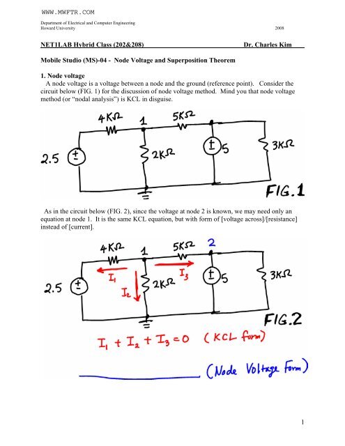
1. <strong>Node</strong> voltage<br />
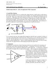
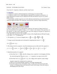
A node voltage is a voltage between a node <strong>and</strong> the ground (reference point). Consider the<br />
circuit below (FIG. 1) for the discussion of node voltage method. Mind you that node voltage<br />
method (or “nodal analysis”) is KCL in disguise.<br />
As in the circuit below (FIG. 2), since the voltage at node 2 is known, we may need only an<br />
equation at node 1. It is the same KCL equation, but with form of [voltage across]/[resistance]<br />
instead of [current].<br />
1
Department of Electrical <strong>and</strong> Computer Engineering<br />
Howard University 2008<br />
2. <strong>Superposition</strong> Theorem<br />
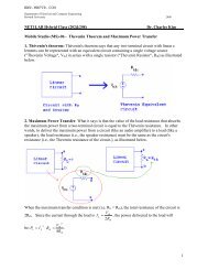
<strong>Superposition</strong> is to add the contribution of each independent source planning in a circuit.<br />
In other words, find a voltage (or current) with only an independent source presence while all<br />
others deactivated, then do the same thing for each of the other independent sources, <strong>and</strong> then<br />
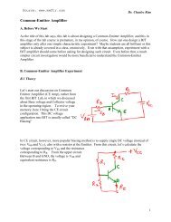
add them all for the final result. Let’s have FIG.3 as our example case. In the two voltage<br />
source circuit, we are asked to find voltage V1, a node voltage.<br />
Since there are two independent sources, we consider one source at a time.<br />
For 5V alone (with 2.5V source deactivated), we have the following circuit (FIG.3A). From the<br />
circuit we find the voltage V1 due only to 5 V source.<br />
Similarly, we find voltage V1 due only to 2.5V source (with 5V source deactivated.)<br />
The final answer is the sum of two V1’s due each to 2.5V <strong>and</strong> 5V source, respectively.<br />
2
Department of Electrical <strong>and</strong> Computer Engineering<br />
Howard University 2008<br />
Mobile Studio (<strong>MS</strong>) <strong>04</strong> – <strong>Node</strong> <strong>Voltage</strong> <strong>and</strong> <strong>Superposition</strong> Theorem<br />
<strong>MS</strong>-<strong>04</strong> Pre-Lab NAME:<br />
1. Implement the circuit of FIG.1 using the Instrumentation board <strong>and</strong> the breadboard.<br />
2. In the circuit of FIG. 2, write node voltage equation(s) AND find the current I 1 . Show your<br />
work.<br />
3
Department of Electrical <strong>and</strong> Computer Engineering<br />
Howard University 2008<br />
3. In the circuit FIG.3A, find the V 1 due to only 5V source. Show you work.<br />
4. From the circuit FIG.3, draw a circuit which has only 2.5 V source, with 5V source<br />
deactivated. Then, find the V 1 due only to 2.5V source.<br />
5. Add the result of 4 <strong>and</strong> 5 above to find the V 1 of the circuit FIG.3.<br />
4
Department of Electrical <strong>and</strong> Computer Engineering<br />
Howard University 2008<br />
Mobile Studio (<strong>MS</strong>) <strong>04</strong> – <strong>Node</strong> <strong>Voltage</strong> <strong>and</strong> <strong>Superposition</strong> Theorem<br />
PROCEDURE<br />
A. <strong>Node</strong> <strong>Voltage</strong> <strong>Method</strong><br />
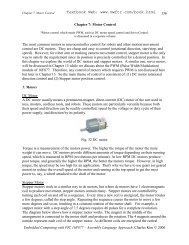
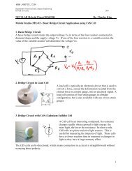
1. Implement the following circuit on the breadboard <strong>and</strong> measure node voltages at node 1 <strong>and</strong><br />
node 2, V 1 <strong>and</strong> V 2 .<br />
2. Measure the voltages across 4K, 2K, <strong>and</strong> 5K, as their polarities shown in the figure shown<br />
below. Then calculate the current I 1 , I 2 , <strong>and</strong> I 3 from the measured voltages.<br />
(a) Is the sum of all three currents zero?<br />
(b) Write your node voltage equation at node 1 <strong>and</strong> compare with the result of (a).<br />
3. By calculating the current through 3K, find the current flowing through the 5V source.<br />
5
Department of Electrical <strong>and</strong> Computer Engineering<br />
Howard University 2008<br />
B. <strong>Superposition</strong> Theorem<br />
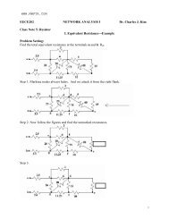
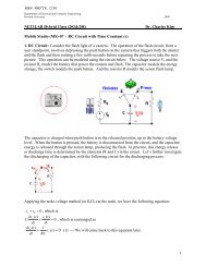
4. For the circuit FIG.1, keep only 5V source. (To deactivate 2.5V source, take the 2.5V source<br />
out first. Then, replace it by wire to make a short circuit). Then measure the voltage V 1 .<br />
5. 1. For the circuit FIG.1, keep only 2.5V source. (To deactivate 5V source, take the 5V source<br />
out first. Then, replace it by wire to make a short circuit). Then measure the voltage V 1 .<br />
6. Add the results of 4 <strong>and</strong> 5 above. Is the sum the same as the node voltage V1 measure in the<br />
step 1 above.<br />
6
Department of Electrical <strong>and</strong> Computer Engineering<br />
Howard University 2008<br />
Mobile Studio (<strong>MS</strong>) <strong>04</strong> – <strong>Node</strong> <strong>Voltage</strong> <strong>and</strong> <strong>Superposition</strong> Theorem<br />
REPORT<br />
Name: ID#: Group#:<br />
1. Discussion on <strong>Node</strong> <strong>Voltage</strong> <strong>Method</strong><br />
2. Discussion on <strong>Superposition</strong> Theorem<br />
7