The Entity Relationship Model
The Entity Relationship Model
The Entity Relationship Model

Create successful ePaper yourself
Turn your PDF publications into a flip-book with our unique Google optimized e-Paper software.
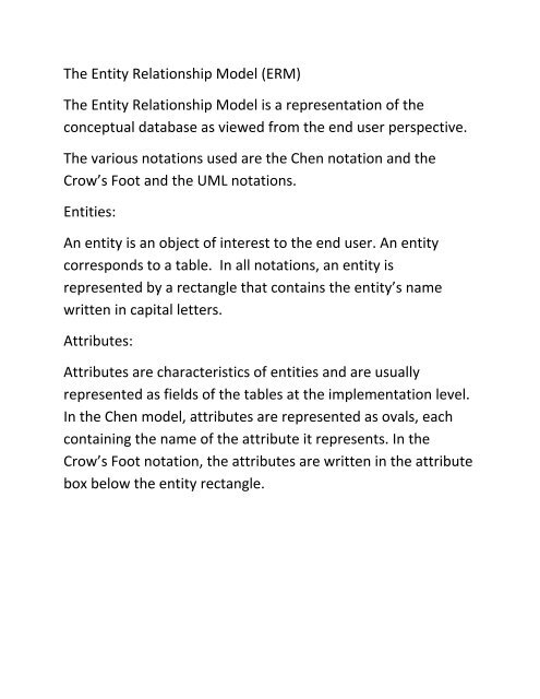
<strong>The</strong> <strong>Entity</strong> <strong>Relationship</strong> <strong>Model</strong> (ERM)<br />
<strong>The</strong> <strong>Entity</strong> <strong>Relationship</strong> <strong>Model</strong> is a representation of the<br />
conceptual database as viewed from the end user perspective.<br />
<strong>The</strong> various notations used are the Chen notation and the<br />
Crow’s Foot and the UML notations.<br />
Entities:<br />
An entity is an object of interest to the end user. An entity<br />
corresponds to a table. In all notations, an entity is<br />
represented by a rectangle that contains the entity’s name<br />
written in capital letters.<br />
Attributes:<br />
Attributes are characteristics of entities and are usually<br />
represented as fields of the tables at the implementation level.<br />
In the Chen model, attributes are represented as ovals, each<br />
containing the name of the attribute it represents. In the<br />
Crow’s Foot notation, the attributes are written in the attribute<br />
box below the entity rectangle.
Chen <strong>Model</strong><br />
Crow’s Foot <strong>Model</strong><br />
STU‐INITIAL<br />
STUDENT<br />
STU‐LNAME<br />
STU‐EMAIL<br />
STU‐LNAME<br />
STU‐FNAME<br />
STUDENT<br />
STU‐PHONE<br />
STU‐FNAME<br />
STU‐INITIAL<br />
STU‐EMAIL<br />
STU‐PHONE<br />
Required and Optional Attributes:<br />
A required attribute is an attribute that must have a value, and<br />
it cannot be left empty. <strong>The</strong> two boldfaced attributes in the<br />
Crow’s Foot notation indicate that the data entry is required.<br />
An optional attribute is an attribute that does not require a<br />
value, it can be left empty.<br />
Domains:<br />
A domain is the set of possible values for a given attribute.<br />
Attribute may share a domain. <strong>The</strong> same attribute name is used<br />
for different entities, and then they share the same domain.
Identifiers or Primary keys:<br />
In ERM, an identifier is one or more attributes that uniquely<br />
identify each instance or tuple. In the relational model, entities<br />
are mapped to tables and the entity identifier is mapped as the<br />
table’s primary key (PK). Identifiers and primary keys are<br />
underlined in the ERD.<br />
Key attributes are also underlined in the relational schema:<br />
TABLE_NAME (KEY_ATTRIBUTE1, ATTRIBUTE2, ……, ATTRIBUTE K)<br />
Composite Identifiers:<br />
Ideally, an entity identifier is only composed of only a single<br />
attribute. However, it is possible to have a composite identifier,<br />
which is a primary key that is composed of more than one<br />
attribute.<br />
Composite and Simple Attributes:<br />
Attributes are classified as simple or composite. A composite<br />
attribute is an attribute that can be further subdivided to yield<br />
additional attributes. For example, the attribute<br />
PHONE_NUMBER can be subdivided into area code and<br />
exchange number.<br />
Single_valued attribute:<br />
A single‐valued attribute is an attribute that can have only a<br />
single value. For example, a person can have only one SSN.
A single valued attribute is not necessarily a simple attribute.<br />
For instance, a part’s serial number such as SE‐08‐02‐16745 is<br />
single‐valued but is a composite attribute that can be divided<br />
into the production region SE, the plant within the region: 08,<br />
the shift: 02 and the part number.<br />
Multi‐valued Attributes:<br />
Multi‐valued attributes are attributes that can have many<br />
values. For example, a person may have several college degrees<br />
, and a household may have several phone numbers. In the<br />
Chen ERM, multivalued attributes are shown by a double line<br />
connecting the attribute to the entity. <strong>The</strong> Crow’s Foot<br />
notation does not identify multivalued attributes.<br />
CAR LICENSE<br />
CAR YEAR<br />
CAR MAKE<br />
CAR_VIN<br />
CAR<br />
CAR COLOR<br />
Implementing Multi‐valued Attributes:<br />
Although conceptually, the model can handle M:N relationships<br />
and mutivalued attributes, they cannot be implemented in the
RDBMS. So, if multivalued attributes exist, the designer must<br />
decide two possible course of action:<br />
1. Within the original entity, create several new attributes,<br />
one for each component of the original mutivalued<br />
attribute. For example, the CAR entity’s attribute<br />
CAR_COLOR can be split to create new attributes<br />
CAR_TOPCOLOR, CAR_BODYCOLOR and CAR_TRIMCOLOR<br />
which are then assigned to the CAR entity. <strong>The</strong> problem<br />
with this approach is that if there are many options for<br />
some tuples and not for all tuples, then the values for<br />
most of the new attributes is going to be NULL.<br />
2. Create a new entity composed by the original multivalued<br />
attribute’s components. <strong>The</strong> new entity allows the<br />
designer to define different values for the attribute. Doing<br />
it this way, allows us to define as many colors for the car<br />
as needed without having to change the table structure.<br />
This is the preferred way to deal with multivalued<br />
attributes. Creating a new entity in a 1:M relationship with<br />
the original entity yields several benefits: it is more<br />
flexible, expandable solution, and it is compatible with the<br />
relational model.
Derived Attributes:<br />
A derived attribute or a computed attribute is an attribute<br />
whose value is calculated (derived) from other attributes.<br />
<strong>The</strong> derived attribute need not be physically stored in the<br />
database.<br />
<strong>Relationship</strong>s:<br />
A relationship is an association between entities. <strong>The</strong><br />
entities that participate in a relationship are also called<br />
participants. A relationship between entities always<br />
operates in both directions. To define the relationship<br />
between the entities name, entity relationships may be<br />
classified as one‐to‐one, one‐to‐many, or many‐to‐many.<br />
Connectivity and Cardinality:<br />
Cardinality expresses the minimum and maximum<br />
number of tuples associated with one tuple of the related<br />
entity. In the ERD cardinality is indicated by placing the<br />
appropriate number besides the entities, using the format<br />
(x,y). <strong>The</strong> first value represents the minimum number of<br />
associated tuples, while the second value represents the<br />
maximum number of associated tuples.<br />
PROFESSOR<br />
teaches<br />
CLASS<br />
(1:1) (1,4)
(1:4) means that each professor teaches up to 4 classes. This<br />
means that a PROFESSOR’ tuple primary key occurs at least<br />
once and at most four times as a foreign key values in the<br />
CLASS table.<br />
(1:1) indicates that each class is taught by one and only one<br />
professor. That is each tuple from the CLASS table is associated<br />
with one and only one tuple from the PROFESSOR’s table.<br />
Existence Dependence:<br />
An entity is said to be existence‐dependent if it can exist in the<br />
database only when it is associated with another related entity.<br />
In implementation terms, an entity is existence‐dependent if it<br />
has a mandatory foreign key, which cannot be NULL. Example:<br />
an employee dependents entity can only exists if there is a<br />
tuple for a specific employee in the EMPLOYEE table.<br />
Strong Entities: If an entity can exist apart from all its related<br />
entities, then it is existence‐independent and it is referred to as<br />
strong entity or regular entity.<br />
<strong>Relationship</strong> Strengths: (Strong <strong>Relationship</strong>s)
<strong>The</strong> concept of relationship strength is related on how primary<br />
keys (PK) are defined among entities. To implement a<br />
relationship, the primary key of one entity ( the parent entity ,<br />
normally on the “one” side of the one‐to‐many relationship)<br />
appears as a foreign key (FK)in the related entity (the “many”<br />
side on the one‐to‐many relationship). Sometimes, the foreign<br />
key is also a primary key in the related entity.<br />
Weak or Non_identifying <strong>Relationship</strong>s:<br />
A weak relationship exists if the primary key of the related<br />
entity does not contain a primary key component of the parent<br />
entity. By default, relationships are established by having the<br />
primary key of the parent entity appear as a foreign key on the<br />
related entity(child entity)<br />
Example, suppose we have a 1:M relationship between COURSE<br />
and CLASS as:<br />
COURSE(CRS_CODE,DEPT_CODE,CRS_DESCRIPTION,CRS_CREDIT)<br />
CLASS(CLASS_CODE, CRS_CODE, CLASS‐SECTION, CLASS_TIME,<br />
ROOM_CODE, PROF_NUM)<br />
In this case, a weak relationship exists between COURSE and<br />
CLASS, because the PK of COURSE is a FK for CLASS.
In the CROW notation, a weak relationship is represented by<br />
placing a dashed relationship line between entities<br />
COURSE<br />
CLASS<br />
PK<br />
CRS_CODE<br />
PK<br />
CLASS_CODE<br />
DEPT_CODE<br />
CRS_DESCRIPTION<br />
generates<br />
FK1<br />
CRS_CODE<br />
CLASS_SECTION<br />
CRS_CREDIT<br />
CLASS_TIME<br />
ROOM_CODE<br />
PROF_NUM<br />
Strong (Identifying ) <strong>Relationship</strong>s:<br />
A strong relationship exists when the primary key of the related<br />
entity contains a primary key component of the parent entity.<br />
For example, suppose the 1:M relationship between CLASS and<br />
COURSE is defined as:<br />
COURSE(CRS_CODE, DEPT_CODE, CRS_DESCRIPTION, CRS_CREDIT)<br />
CLASS(CRS_CODE, CLASS_CODE, CLASS‐SECTION, CLASS_TIME,<br />
ROOM_CODE, PROF_NUM)
In this case, the CLASS entity primary key is composed of<br />
CRS_CODE and CLASS_SECTION. <strong>The</strong>refore, a strong<br />
relationship exists between COURSE and CLASS.<br />
Weak Entities:<br />
In contrast to strong or regular entities mentioned earlier, a<br />
weak entity is one that meets two conditions:<br />
1. <strong>The</strong> entity is existence‐dependent, it cannot exist without<br />
the entity with which it has a relationship.<br />
2. <strong>The</strong> entity has a primary key that is partially or totally<br />
derived from the parent entity in the relationship.<br />
For example, a company insurance policy may cover an<br />
employee and their dependents. An EMPLOYEE may or may<br />
not have any DEPENDANTS, however a DEPENDENT must be<br />
associated with an EMPLOYEE and if the EMPLOYEE is<br />
deleted then the DEPENDENT is also deleted. DEPENDENT is<br />
a weak entity in the relationship “EMPLOYEE has<br />
DEPENDENT”.<br />
<strong>Relationship</strong> Participation:<br />
Participation in a relationship is either optional or<br />
mandatory.<br />
Optional participation: means that one entity occurrence<br />
does not require a corresponding entity occurrence in the
elationship. For example, an EMPLOYEE may have no<br />
DEPENDENT. <strong>The</strong>refore the DEPENDENT entity is optional for<br />
the EMPLOYEE entity. <strong>The</strong> Crow’s Foot notation , an optional<br />
relationship is shown by drawing a small circle(O) on the side<br />
of the optional entity. <strong>The</strong> corresponding minimal cardinality<br />
is 0.<br />
Mandatory participation: means that one entity occurrence<br />
requires a corresponding entity recurrence in a particular<br />
relationship. If no optionality symbol is depicted, the<br />
relationship is assumed to be mandatory. <strong>The</strong> existence of a<br />
mandatory participation implies a connectivity of 1 and a<br />
minimum cardinality of 1.<br />
<strong>Relationship</strong> degrees:<br />
A relationship degree indicates the number of entities or<br />
participants associated with the relationship.<br />
A unary relationship exists when an association is maintained<br />
within a single entity. For example: an employee within the<br />
EMPLOYEE entity is the manager of one or more employees<br />
within the entity. In this case, the "manages" relationship<br />
means that EMPLOYEE requires that another EMPLOYEE be<br />
the manager that is EMPLOYEE has a relationship with itself .
This is known as a recursive relationship. Recursive<br />
relationships are represented like:<br />
manages<br />
EMPLOYEE<br />
A binary relationship requires two entities to be related.<br />
<strong>The</strong>se are the most common type of relationships and<br />
usually higher order relationships are decomposed into<br />
appropriate equivalent binary relationships.<br />
A ternary relationship exists when three entities are related.<br />
Although, they are rare, they are sometimes necessary. A<br />
ternary relationship implies an association among three<br />
different entities. Example:<br />
• A DOCTOR writes one or more PRESCRPTIONS<br />
• A PATIENT may receive one or more PRESCRIPTIONS<br />
• A DRUG may appear in one or more PRESCRIPTIONS.
A doctor can be scheduled for many appointments, but<br />
may not have any scheduled at all. Each appointment is<br />
scheduled with exactly 1 doctor. A patient can schedule 1<br />
or more appointments. One appointment is scheduled<br />
with exactly 1 patient.<br />
An appointment must generate exactly 1 bill, a bill is<br />
generated by only 1 appointment. One payment is applied<br />
to exactly 1 bill, and 1 bill can be paid off over time by<br />
several payments. A bill can be outstanding, having<br />
nothing yet paid on it at all. One patient can make many<br />
payments, but a single payment is made by only 1 patient.<br />
Some patients are insured by an insurance company. If<br />
they are insured, they can only carry insurance with one<br />
company. An insurance company can have many patients<br />
carry their policies. For patients that carry insurance, the<br />
insurance company will make payments, each single<br />
payment is made by exactly 1 insurance company.