Standard Air Capacitors - Haefely Test AG
Standard Air Capacitors - Haefely Test AG
Standard Air Capacitors - Haefely Test AG

You also want an ePaper? Increase the reach of your titles
YUMPU automatically turns print PDFs into web optimized ePapers that Google loves.
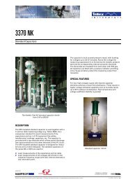
3320<br />
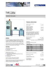
<strong>Standard</strong> <strong>Air</strong> <strong>Capacitors</strong><br />
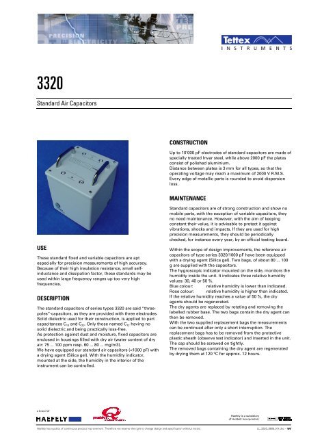
CONSTRUCTION<br />
Up to 10’000 pF electrodes of standard capacitors are made of<br />
specially treated Invar steel, while above 2000 pF the plates<br />
consist of polished aluminium.<br />
Distance between plates is 3 mm for all types, so that the<br />
operating voltage may reach a maximum of 2000 V R.M.S.<br />
Every edge of metallic parts is rounded to avoid dispersion<br />
loss.<br />
MAINTENANCE<br />
USE<br />
These standard fixed and variable capacitors are apt<br />
especially for precision measurements of high accuracy.<br />
Because of their high insulation resistance, small selfinductance<br />
and dissipation factor, these standards may be<br />
used within large frequency ranges up too very high<br />
frequencies.<br />
DESCRIPTION<br />
The standard capacitors of series types 3320 are said “threepoles“-capacitors,<br />
as they are provided with three electrodes.<br />
Solid dielectric used for their construction, is applied to part<br />
capacitances C 10 and C 20 . Only those named C 12 having no<br />
solid dielectric and being practically loss-free.<br />
As protection against dust and moisture, fixed capacitors are<br />
enclosed in housings filled with dry air (water content of dry<br />
air: 75 ... 100 ppm resp. 60 ... 80 ... mg/m3).<br />
We have equipped our standard air capacitors (
TECHNICAL DATA<br />
Dissipation factor tan δ 12 : < 1 x 10 -5<br />
Operating voltage, max.: 2000 V R.M.S.<br />
Temperature coefficient<br />
C 12 ≤ 1000 pF:<br />
about + 10 x 10 -6 /°C<br />
C 12 > 1000 pF:<br />
about + 20 ... 30 x 10 -6 /°C<br />
Inductance:<br />
about 2 ... 5 x 10 -8 H<br />
Stability:<br />
< 50 x 10 -6 /year<br />
Depending of frequency<br />
up to 10 kHz: < 1 x 10 -5<br />
Depending of voltage with regard<br />
to C 12 and tan δ 12 : < 1 x 10 -6<br />
ACCURACY<br />
Fix capacitors: Please see table at page 4<br />
The value of main capacitance C 12 = calibrated capacitance<br />
is given with an accuracy of ± 0.001 % in the test certificate<br />
delivered with the standards. Further, for fixed capacitors<br />
the label indicates part capacitances C 10 and C 20 with an<br />
accuracy of ± 0.1 pF.<br />
On request the standard capacitors may be delivered with<br />
an official report from a laboratory of metrology.<br />
CALIBRATION<br />
Main capacitance C 12 is calibrated at 23°C and a rel. air<br />
humidity by 20 %.<br />
ACCESSORIES<br />
Each capacitor is supplied with the following accessories:<br />
2 spare bags of dry agent no. 08189-00<br />
but only for types up to 3320/1000 pF<br />
As connection cable unipolar, shielded cables<br />
no. 101 W or no. 111 W<br />
(furnished with shielded plugs) are available.<br />
<strong>Standard</strong> lengths 1, 2, 5, 10 and 20 m.<br />
Unipolar sockets for shielded plugs are available:<br />
Socket without insulation no. 10691-00<br />
Socket without insulation no. 12361-00<br />
Dissipation factor tan δ-standard type 3721<br />
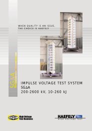
EQUIVALENT CIRCUITS FOR CAPACITORS<br />
For absolute precision measurements, only the calibrated<br />
capacitance C 12 has to be used, the partial capacitances C 10<br />
and C 20 being eliminated.<br />
a brand of<br />
<strong>Haefely</strong> is a subsidiary<br />
of Hubbell Incorporated.<br />
<strong>Haefely</strong> has a policy of continuous product improvement. Therefore we reserve the right to change design and specification without notice. LL_3320_0808_KH.doc – 2/4
TEST CONNECTIONS<br />
While using this capacitors for precision measurements in<br />
bridge combinations, it is indispensable to make use of a<br />
potential regulating device with a guard-potential regulator<br />
(Fig.1), or better of a Wagner’s auxiliary arm (Fig.2), in order<br />
to eliminate, among others, the partial capacitances of the<br />
bridge and cables with respect to earth, as well as both<br />
partial capacitances C 10 and C 20 of the capacitor. In such case,<br />
the housing 0 is connected to earth and the indicator corner<br />
points of the bridge will be submitted earth potential.<br />
While using, a guard-potential regulator P, the capacitance<br />
C 10 is external to the bridge. C 20 is inoperative, because of the<br />
lock of potential difference when the bridge is balanced<br />
(Fig. 1).<br />
In case of measurements with the aid of a Wagner’s auxiliary<br />
guard circuit W the capacitance C 10 is external to the bridge.<br />
C 20 is inoperative because of the lack of potential difference<br />
when the bridge is balanced (Fig. 1).<br />
In case of measurements with the aid of a Wagner’s auxiliary<br />
guard circuit W, the capacitance C10 is parallel to the arm C a<br />
of this circuit; C 20 is inefficient, no potential difference<br />
appearing at balance (Fig. 2).<br />
If the lowest bridge point is connected to earth - that means<br />
that the measuring voltage has one grounded pole, - the<br />
housing of the standard capacitor as well as the indicator<br />
corner point c of the auxiliary circuit have to be connected to<br />
the shielding of the bridge, which is disconnected from the<br />
earth. In such case the guard-potential regulator will be<br />
connected between the shield and earth.<br />
For measurements without Wagner’s guard circuit or guardpotential<br />
regulator the capacitor housing should be<br />
connected to the earthed point of the bridge, respectively to<br />
point v (Fig. 3). Both of partial capacitances, C 10 lays parallel<br />
to voltage source, having so far no influence on<br />
measurements. C 20 is in parallel with one of the lower arm<br />
resistance and has an effect only on the phase of the bridge.<br />
Those effects can be considered by a correction (the<br />
capacitance of the lead-in cables, etc., should also be taken<br />
into consideration!).<br />
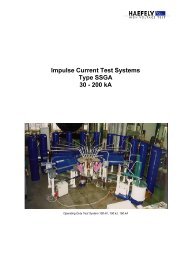
CONSTRUCTION AND VIEW<br />
Legend:<br />
1. External Housing (screen)<br />
2 Internal Housing (screen)<br />
3 Dry air<br />
4 Base Plate (screen)<br />
5 Electrode Plates 2<br />
6 Electrode Plates 1<br />
7 Plate Distance = 3mm<br />
8 Plate Thickness = 1 resp. 1.5 mm<br />
9 Tune Capacitor<br />
10 Insulators<br />
11 Junction Bushings 1 and 2<br />
a brand of<br />
<strong>Haefely</strong> is a subsidiary<br />
of Hubbell Incorporated.<br />
<strong>Haefely</strong> has a policy of continuous product improvement. Therefore we reserve the right to change design and specification without notice. LL_3320_0808_KH.doc – 3/4
LIST OF TYPES<br />
Type Capacitance Accuracy C 12 Partial capacitace Dimensions<br />
Net weights<br />
C 12<br />
C 10 - C 20<br />
No. pF % ∼ pF mm/ (in) ∼ kg ∼ lbs<br />
3320/10 10 ± 0.02 % 60 - 70 260x260x310<br />
(10.2x10.2x12.2)<br />
3320/20*) 20 ± 0.01% 60 - 80 260x260x310<br />
(10.2x10.2x12.2)<br />
3320/50 *) 50 ± 0.005 % 60 - 80 260x260x310<br />
(10.2x10.2x12.2)<br />
3320/100 100 ± 0.005 % 60 - 80 260x260x310<br />
(10.2x10.2x12.2)<br />
3320/200 *) 200 ± 0.005 % 60 - 80 260x260x310<br />
(10.2x10.2x12.2)<br />
3320/500 *) 500 ± 0.005 % 60 - 90 260x260x310<br />
(10.2x10.2x12.2)<br />
3320/1’000 1’000 ± 0.005 % 70 - 90 260x260x310<br />
(10.2x10.2x12.2)<br />
3320/2’000 *) 2’000 ± 0.01 % 140 -200 360x360x450<br />
(14.2x14.2x17.7)<br />
3320/5’000 *) 5’000 ± 0.02 % 140 - 200 360x360x450<br />
(14.2x14.2x17.7)<br />
3320/10’000 10’000 ± 0.02 % 170 - 250 360x360x450<br />
(14.2x14.2x17.7)<br />
10 22<br />
10 22<br />
10 22<br />
10 22<br />
11 24<br />
12 26.4<br />
13 28.6<br />
24 53<br />
29 64<br />
35 72<br />
* special design<br />
European Contact<br />
<strong>Haefely</strong> <strong>Test</strong> <strong>AG</strong><br />
Lehenmattstrasse 353<br />
4052 Basel<br />
Switzerland<br />
+ 41 61 373 4111<br />
+ 41 61 373 4912<br />
sales@haefely.com<br />
Locate your local sales representative at<br />
www.haefely.com<br />
USA Contact<br />
Hipotronics Inc.<br />
1650 Route 22<br />
PO Box 414<br />
Brewster, NY 10509 USA<br />
+ 1 845 279 8091<br />
+ 1 845 279 2467<br />
sales@hipotronics.com<br />
a brand of<br />
<strong>Haefely</strong> is a subsidiary<br />
of Hubbell Incorporated.<br />
<strong>Haefely</strong> has a policy of continuous product improvement. Therefore we reserve the right to change design and specification without notice. LL_3320_0808_KH.doc – 4/4