You also want an ePaper? Increase the reach of your titles
YUMPU automatically turns print PDFs into web optimized ePapers that Google loves.
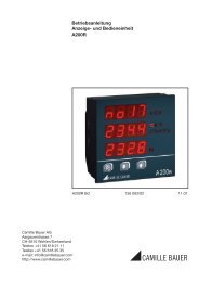
Device handbook<br />
<strong>APLUS</strong><br />
Operating Instructions <strong>APLUS</strong><br />
157 679-07 07/2011<br />
Camille Bauer AG<br />
Aargauerstrasse 7<br />
CH-5610 Wohlen / Switzerland<br />
Phone: +41 56 618 21 11<br />
Telefax: +41 56 618 35 35<br />
e-Mail: info@camillebauer.com<br />
http://www.camillebauer.com
Contents<br />
1. Security notes .................................................................................................................. 4<br />
2. Scope of supply ............................................................................................................... 4<br />
3. Device overview ............................................................................................................... 4<br />
3.1 Brief description ...................................................................................................................... 4<br />
3.2 Possible modes of operation ................................................................................................... 5<br />
3.3 Monitoring and alarming .......................................................................................................... 6<br />
3.3.1 Alarming concept ................................................................................................................................ 6<br />
3.3.2 Logic components ............................................................................................................................... 8<br />
3.3.3 Limit values ......................................................................................................................................... 9<br />
3.3.4 Sequence of evaluation .................................................................................................................... 10<br />
3.4 Free Modbus image ............................................................................................................ 11<br />
4. Mechanical mounting .................................................................................................... 12<br />
4.1 Panel cutout .......................................................................................................................... 12<br />
4.2 Mounting of the device .......................................................................................................... 12<br />
4.3 Demounting of the device ..................................................................................................... 12<br />
5. Electrical connections ................................................................................................... 13<br />
5.1 General safety notes ............................................................................................................. 13<br />
5.2 Electrical connections of the I/Os .......................................................................................... 14<br />
5.3 Possible cross sections ......................................................................................................... 14<br />
5.4 Inputs .................................................................................................................................... 15<br />
5.5 Power supply ........................................................................................................................ 19<br />
5.6 Relays ................................................................................................................................... 19<br />
5.7 Digital inputs and outputs ...................................................................................................... 20<br />
5.8 Analog outputs ...................................................................................................................... 22<br />
5.9 Modbus interface RS485 ....................................................................................................... 22<br />
5.10 Profibus DP interface ........................................................................................................... 23<br />
6. Commissioning .............................................................................................................. 24<br />
6.1 Software installation CB-Manager ......................................................................................... 24<br />
6.2 Parametrization of the device functionality ............................................................................ 25<br />
6.3 Installation check .................................................................................................................. 26<br />
6.4 Installation of Ethernet devices ............................................................................................. 27<br />
6.4.1 Connection ..................................................................................................................................... 27<br />
6.4.2 Network installation using the CB-Manager software .................................................................... 28<br />
6.4.3 Network installation by menas of local programming .................................................................... 29<br />
6.4.4 Time synchronization via NTP-protocol ......................................................................................... 30<br />
6.4.5 TCP ports for data transmission .................................................................................................... 30<br />
6.5 Installation of Profibus DP devices ........................................................................................ 31<br />
6.6 Protection against device data changing ............................................................................... 32<br />
7. Operating the device ..................................................................................................... 33<br />
7.1 Display and operating elements ............................................................................................ 33<br />
7.2 Operating modes .................................................................................................................. 34<br />
7.3 Setting the display brightness ............................................................................................... 35<br />
7.4 Display modes ...................................................................................................................... 36<br />
7.5 Meter reading ........................................................................................................................ 39<br />
7.6 Alarm handling ...................................................................................................................... 40<br />
7.6.1 Alarm state display on the device ..................................................................................................... 40<br />
7.6.2 Display of alarm texts ........................................................................................................................ 40<br />
7.6.3 Acknowledgment of alarms via display ............................................................................................. 41<br />
2/86 Device handbook <strong>APLUS</strong>, 157 679-06, 07/2011
7.7 Resetting of measurements ................................................................................................... 42<br />
7.8 Configuration ......................................................................................................................... 43<br />
7.8.1 Selection of the parameter to edit ......................................................................................................47<br />
7.8.2 Discrete selection ...............................................................................................................................48<br />
7.8.3 Setting value ......................................................................................................................................48<br />
7.9 Data logger ............................................................................................................................ 49<br />
7.9.1 Activation of data logger recording ....................................................................................................49<br />
7.9.2 SD card ..............................................................................................................................................49<br />
7.9.3 Access to logger data ........................................................................................................................49<br />
7.9.4 Logger data analysis ..........................................................................................................................50<br />
8. Service and maintenance ............................................................................................. 51<br />
8.1 Protection of data integrity ..................................................................................................... 51<br />
8.2 Calibration and new adjustment ............................................................................................ 51<br />
9. Technical data ............................................................................................................... 52<br />
10. Dimensional drawings .................................................................................................. 57<br />
Annex ................................................................................................................................... 59<br />
A Description of measured quantities ............................................................................. 59<br />
A1 Basic measurements ............................................................................................................. 59<br />
A2 Harmonic analysis ................................................................................................................. 62<br />
A3 System imbalance ................................................................................................................. 63<br />
A4 Reactive power...................................................................................................................... 64<br />
A5 Mean values and trend .......................................................................................................... 66<br />
A6 Meters ................................................................................................................................... 67<br />
B Display matrices in FULL mode ................................................................................... 68<br />
B0 Used abbreviations for the measurements ............................................................................ 68<br />
B1 Display matrix single phase system ....................................................................................... 75<br />
B2 Display matrix Split-phase (two-phase) systems .................................................................... 76<br />
B3 Display matrix 3-wire system, balanced load ......................................................................... 77<br />
B4 Display matrix 3-wire systems, unbalanced load ................................................................... 78<br />
B5 Display matrix 3-wire systems, unbalanced load, Aron .......................................................... 79<br />
B6 Display matrix 4-wire system, balanced load ......................................................................... 80<br />
B7 Display matrix 4-wire systems, unbalanced load ................................................................... 81<br />
B8 Display matrix 4-wire system, unbalanced load, Open-Y ....................................................... 82<br />
B9 Display matrix of mean-values of power quantities ................................................................ 83<br />
C Declaration of conformity ............................................................................................. 84<br />
INDEX ................................................................................................................................... 85<br />
3/86 Device handbook <strong>APLUS</strong>, 157 679-06, 07/2011
1. Security notes<br />
Device may only be disposed in a professional manner !<br />
The installation and commissioning should only be carried out by trained personnel.<br />
Check the following points before commissioning:<br />
– that the maximum values for all the connections are not exceeded, see "Technical data"<br />
section,<br />
– that the connection wires are not damaged, and that they are not live during wiring,<br />
– that the power flow direction and the phase rotation are correct.<br />
The instrument must be taken out of service if safe operation is no longer possible (e.g. visible<br />
damage). In this case, all the connections must be switched off. The instrument must be<br />
returned to the factory or to an authorized service dealer.<br />
It is forbidden to open the housing and to make modifications to the instrument. The instrument<br />
is not equipped with an integrated circuit breaker. During installation check that a labeled switch<br />
is installed and that it can easily be reached by the operators.<br />
Unauthorized repair or alteration of the unit invalidates the warranty.<br />
2. Scope of supply<br />
- Measurement device <strong>APLUS</strong><br />
- Safety instructions<br />
- Software and documentation CD<br />
- Connection set basic unit: Plug-in terminals and mounting clamps<br />
- Optional: Connection set I/O extension: Plug-in terminals<br />
3. Device overview<br />
3.1 Brief description<br />
The <strong>APLUS</strong> is a comprehensive instrument for the universal measurement, monitoring and power quality<br />
analysis in power systems. The device can be adapted fast and easily to the measurement task by means<br />
of the CB-Manager software. The universal measurement system of the device may be used directly for<br />
any power system, from single phase up to 4-wire unbalanced networks, without hardware modifications.<br />
Independent of measurement task and outer influences always the same high performance is achieved.<br />
Using additional, optional components the opportunities of the <strong>APLUS</strong> may be extended. You may choose<br />
from I/O extensions, communication interfaces or data logger. The nameplate on the device gives further<br />
details about the present version.<br />
The version with top-hat rail adapter instead of the display has the same dimensions and connections as<br />
the version with display and supports the same options.<br />
4/86 Device handbook <strong>APLUS</strong>, 157 679-06, 07/2011
3.2 Possible modes of operation<br />
The <strong>APLUS</strong> can cover a wide range of possible input ranges without any hardware variance. The adaption<br />
to the input signal is performed by means of variable amplifying levels for current and voltage inputs.<br />
Depending on the application it makes sense to fix these levels by means of the configuration or to let<br />
them stay variable to achieve a maximum accuracy during measurement. The differentiation, if the<br />
amplifying remains constant or is adapted to the present value, is done during the definition of the input<br />
configuration by means of the parameter "auto-scaling".<br />
The disadvantage of auto-scaling is that when an amplifying level needs to be changed, a settling time of<br />
at least one cycle of the power frequency must be allowed until the signals have stabilized again. During<br />
this short time the measurement results remain frozen.<br />
Continuous measurement<br />
An absolute uninterrupted measurement of all quantities assumes that auto-scaling is deactivated for both<br />
voltage and current inputs.<br />
Metering<br />
The uncertainty of the active energy meters of the <strong>APLUS</strong> is given with class 0.5S. To fulfill the high<br />
requirements of the underlying meter standard EN 62053-22 also small currents have to be measured<br />
very accurate. To do so, auto-scaling must be activated for current inputs. For metering applications the<br />
system voltage is assumed to be quite constant, nominal value acc. standard, wherefore auto-scaling for<br />
voltages is not required. The subsequent example shows an appropriate configuration, which also<br />
conforms to the factory setting of the device.<br />
Dynamic monitoring of limit values<br />
An important criterion when monitoring the quality of the supply voltage is the possibility to detect short<br />
sags of the system voltage. To be able to follow the progress of the voltage auto-scaling of the voltage<br />
inputs should be deactivated. Thereby you have to consider that a possible swell of the voltage may be<br />
detected only up to the configured overriding (20% of rated voltage in the above example), because the<br />
switching of the measurement range is locked in both directions.<br />
This applies analogously to all quantities of the system, whose progress should be monitored. For power<br />
quantities the voltage amplification as well as the current amplification is influenced. However, which basic<br />
quantities may vary how much can differ from application to application.<br />
5/86 Device handbook <strong>APLUS</strong>, 157 679-06, 07/2011
3.3 Monitoring and alarming<br />
The logic module integrated in the <strong>APLUS</strong> is a powerful feature to monitor critical situations without delay<br />
on device side. By implementing this local intelligence a safe monitoring can be realized which is<br />
independent of the readiness of the control system.<br />
3.3.1 Alarming concept<br />
How alarms are handled is decided during the configuration of the device. For that in the logic module you<br />
can define if LED's are used for alarm state display and how resp. when a possibly activated action, such<br />
as the switching of a relay, will be reset. These configuration parameters are highlighted in yellow in the<br />
following chart.<br />
Y<br />
Perform action<br />
Action<br />
resettable<br />
?<br />
N<br />
Alarm state<br />
still persists ?<br />
N<br />
Action reset<br />
Y<br />
Y<br />
Y<br />
Action<br />
configurated<br />
?<br />
N<br />
Reset<br />
?<br />
N<br />
ALARM<br />
No action<br />
LED used<br />
for alarm<br />
display ?<br />
N<br />
- LED ON<br />
- fast flashing<br />
► Acknowledgment: This procedure affects the state of the LED only<br />
Alarm<br />
acknowledged<br />
?<br />
Alarm state<br />
still persists ?<br />
slow flashing<br />
Stop flashing<br />
Alarm state<br />
still persists ?<br />
LED OFF<br />
If an alarm state is visualized via LED, its occurence must be acknowledged via display (see:<br />
Acknowledgment of alarms via display), no matter if it is still active (fast flashing) or has dropped-out<br />
already (slow flashing). By acknowledging an alarm, only the flashing of the LED stops, but a reset of the<br />
alarm action is performed only if the display is configured as a possible source for alarm reset.<br />
► Alarm reset: This procedure affects the states of the follow-up action and<br />
When an alarm state occurs a follow-up action (e.g. the switching of a relay) can be triggered. This followup<br />
action is normally reset as soon as the alarm condition no longer exists. But the alarm handling may be<br />
configured as well in a way, that only by means of an alarm reset the subsequent operation is withdrawn.<br />
This way an alarm remains stored until a reset is performed, even if the alarm situation no longer exists.<br />
Possible sources for an alarm reset are the display, a digital input, another logical state of the logic<br />
module or a command via the bus interface.<br />
Hint: If an alarm is reset, the alarm state visualized via LED is acknowledged at the same time.<br />
On the next page some signal flow examples are shown.<br />
6/86 Device handbook <strong>APLUS</strong>, 157 679-06, 07/2011<br />
Y<br />
Y<br />
N<br />
N<br />
Y<br />
N<br />
Y
Z: Logic output determined from all involved logic<br />
inputs<br />
D: Corresponds to signal Z, delayed by the switch-in<br />
resp. dropout delay<br />
A: Output signal of the logic function<br />
S: State of the subsequent operation (e.g. of a<br />
relay), corresponds normally to A, but may be<br />
inverted (subsequent operation: relay OFF)<br />
1) Alarm reset inactive, switch-in and dropout delay 3s, follow-up action not inverted<br />
Acknowledgment of<br />
LED, inactive alarm<br />
Acknowledgment of<br />
LED, active alarm<br />
2) Alarm reset active, switch-in and dropout delay 0s, follow-up action inverted<br />
Reset when alarm is<br />
inactive<br />
Reset when alarm is<br />
still active<br />
7/86 Device handbook <strong>APLUS</strong>, 157 679-06, 07/2011
3.3.2 Logic components<br />
The logic outputs are calculated via a two level logical combination of states, which are present at the<br />
inputs. Usable components are AND, OR and XOR gates as well as their inversions NAND, NOR and<br />
XNOR.<br />
The principal function of the logical gates is given in the following table, for simplicity shown for gates with<br />
two inputs only.<br />
function symbol<br />
AND<br />
NAND<br />
OR<br />
NOR<br />
XOR<br />
XNOR<br />
older symbols<br />
ANSI 91-1984 DIN 40700 (alt)<br />
truth table plain text<br />
A B Y<br />
0 0 0<br />
0 1 0<br />
1 0 0<br />
1 1 1<br />
A B Y<br />
0 0 1<br />
0 1 1<br />
1 0 1<br />
1 1 0<br />
A B Y<br />
0 0 0<br />
0 1 1<br />
1 0 1<br />
1 1 1<br />
A B Y<br />
0 0 1<br />
0 1 0<br />
1 0 0<br />
1 1 0<br />
A B Y<br />
0 0 0<br />
0 1 1<br />
1 0 1<br />
1 1 0<br />
A B Y<br />
0 0 1<br />
0 1 0<br />
1 0 0<br />
1 1 1<br />
Function is true if all input<br />
conditions are fulfilled<br />
Function is true if at least<br />
one of the input<br />
conditions is not fulfilled<br />
Function is true if at least<br />
one of the input<br />
conditions is fulfilled<br />
Function is true if none of<br />
the input conditions is<br />
fulfilled<br />
Function is true if exactly<br />
one of the input<br />
conditions is fulfilled<br />
Function is true if all of<br />
the input conditions are<br />
fulfilled or all conditions<br />
are not fulfilled<br />
The logic components of the first level may combine up to three, the components of the second level up to<br />
four input conditions. If individual inputs are not used, their state is automatically set to a condition which<br />
has no influence on the logic result.<br />
8/86 Device handbook <strong>APLUS</strong>, 157 679-06, 07/2011
3.3.3 Limit values<br />
States of limit values are the most important input quantities of the logic module. Depending on the<br />
application, limits either monitor the exceeding of a given value (upper limit) or the fall below a given value<br />
(lower limit). Limits are defined by means of two parameters, the limit for the ON and the limit for the OFF<br />
state. The hysteresis is the difference between these two values.<br />
Upper limit: The limit for ON state (L.On) is higher than the limit for the OFF state (L.OFF)<br />
Limit for ON state<br />
Limit for OFF state<br />
Limit state 0<br />
► The state 1 (true) results if the limit for ON state is exceeded. It remains until the value falls below the<br />
limit for OFF state again.<br />
► The state 0 (false) results if the limit for ON state is not yet reached or if, following the activation of the<br />
limit value, the value falls below the limit for OFF state again.<br />
Lower limit: The limit for ON state (L.On) is smaller than the limit for OFF state (L.OFF)<br />
Limit for OFF state<br />
Limit for ON state<br />
Limit state 0<br />
► The state 1 (true) results if the value falls below the limit for ON state. It remains until the value<br />
exceeds the limit for OFF state again.<br />
► The state 0 (false) results if the value is higher than the limit for ON state or if, following the activation<br />
of the limit value, the value exceeds the limit for OFF state again.<br />
If for a limit value the limit for ON state and the limit for OFF state are configured to<br />
the same value, it will be treated as an upper limit value with a hysteresis of 0%.<br />
Limit values may be used to control the running of operating hour counters. As long as the limit values<br />
are fulfilled (logical 1) the operating hour counters keep on running. Not only operating times may be<br />
measured, but e.g. time under overload condition (additional stress) as well.<br />
9/86 Device handbook <strong>APLUS</strong>, 157 679-06, 07/2011<br />
1<br />
1
3.3.4 Sequence of evaluation<br />
The evaluation of the logic module is performed from top to bottom and from left to right:<br />
1. Y1, Y2, Y3, Y4<br />
2. Z1, Z2, Z3, Z4<br />
3. D1, D2, D3, D4<br />
4. A1, A2, A3, A4<br />
► The evaluation is performed once each cycle of the power frequency, e.g. every 20ms at 50Hz. But the<br />
time between two evaluations will never be longer than 25ms.<br />
► If the logical states Y1...Y4, Z1...Z4, D1...D4 and A1...A4 are used as inputs, their changed states will<br />
be included in the evaluation of the next interval<br />
► Exception: In the first evaluation level the state of previous logical functions may be used as input<br />
without delay, e.g. the state Y1 for the logical functions with output Y2, Y3 or Y4.<br />
10/86 Device handbook <strong>APLUS</strong>, 157 679-06, 07/2011
3.4 Free Modbus image<br />
Accessing measured data of a Modbus device often needs some special effort, if the interesting<br />
measurements are stored in different, non continuous register areas. This way multiple telegrams must be<br />
sent to the device to read all data. This needs time and it's very likely, that the measurements don't<br />
originate from the same measurement cycle.<br />
A free assembly of the data to read helps a lot. The <strong>APLUS</strong> supports, along with the still available classical<br />
Modbus image with thousands of registers, the facility to assemble two different images, which may be<br />
read with one telegram only. These freely assembled images are refreshed after each measurement cycle<br />
and therefore always provide the most present values.<br />
The free float image<br />
Up to 60 instantaneous, mean, unbalance or THD/TDD values may be arranged in any sequence on the<br />
register addresses 41840-41958. All of these values are floating point numbers, which allocate 2 registers<br />
per value. Meter values are not possible because they have another format.<br />
The free integer image<br />
Some older control systems are not able to handle float values. To make it possible to work with the data<br />
of the device up to 20 16-Bit integer values can be derived from the existing measurement values. These<br />
values will then be stored in the free Modbus image (register 41800 up to 41819) as integer values with<br />
selectable range of values.<br />
Example: Current transformer 100/5A, measurement current phase 1, over range 20%<br />
► The reference value is 120A (maximum measurable current)<br />
► The integer value shall be 12'000 if the measurement is 120A<br />
After selecting the measured quantity and entering the register value of 12'000 automatically a scaling<br />
factor of 100.0 is calculated. The measurement I1 therefore will be multiplied by 100.0 before it is<br />
converted into an integer value and stored in the Modbus image.<br />
Also in the integer image instantaneous, mean, unbalance or THD/TDD values may be arranged.<br />
For devices with Profibus interface the Modbus image is used for the assembly of the<br />
cyclical telegram. Via Modbus the same image can be used, but it’s not possible to use it<br />
independently.<br />
The Modbus communication of the <strong>APLUS</strong> is described in a separate document. Depending on the<br />
communication hardware selected, either the manual for Modbus/RTU or Modbus/TCP protocol should be<br />
used. These documents may be found on the software CD or can be downloaded via our homepage<br />
http://www.camillebauer.com.<br />
► W157 695: Modbus/RTU interface <strong>APLUS</strong> (communication interface RS485)<br />
► W162 636: Modbus/TCP interface <strong>APLUS</strong> (communication interface Ethernet)<br />
11/86 Device handbook <strong>APLUS</strong>, 157 679-06, 07/2011
4. Mechanical mounting<br />
► The standard version of the <strong>APLUS</strong> is designed for panel mounting as shown below<br />
► The version without display with top-hat rail adapter may be clipped onto a top-hat rail according to<br />
EN50022<br />
4.1 Panel cutout<br />
Please ensure that the operating temperature limits are not exceeded when<br />
determining the place of mounting (place of measurement):<br />
4.2 Mounting of the device<br />
-10 ... 55°C<br />
The <strong>APLUS</strong> is suitable for panel widths up to 10mm.<br />
4.3 Demounting of the device<br />
Dimensional drawing <strong>APLUS</strong>:<br />
See section 10<br />
a) Slide the device into the cutout from<br />
the outside<br />
b) From the side slide in the mounting<br />
clamps into the intended openings and<br />
pull them back about 2 mm<br />
c) Tighten the fixation screws until the<br />
device is tightly fixed with the panel<br />
The demounting of the device may be performed only if all connected wires are out of service. Remove<br />
all plug-in terminals and all connections of the current and voltage inputs. Pay attention to the fact, that<br />
current transformers must be shortened before removing the current connections to the device. Then<br />
demount the device in the opposite order of mounting (4.2).<br />
12/86 Device handbook <strong>APLUS</strong>, 157 679-06, 07/2011
5. Electrical connections<br />
5.1 General safety notes<br />
Ensure under all circumstances that the leads are free of potential<br />
when connecting them !<br />
Please observe that the data on the type plate must be adhered to !<br />
The national provisions (e.g. in Germany VDE 0100 “Conditions concerning the erection of heavy<br />
current facilities with rated voltages below 1000 V”) have to be observed in the installation and material<br />
selection of electric lines!<br />
1<br />
2<br />
3<br />
4<br />
5<br />
6<br />
Symbol Meaning<br />
Device may only be disposed of in a professional manner!<br />
Double insulation, device of protection class 2<br />
Nameplate of a<br />
device equipped<br />
with RS485<br />
interface and I/O<br />
extension 1<br />
CE conformity mark. The device fulfills the requirements of the applicable EC<br />
directives. See declaration of conformity.<br />
Caution! General hazard point. Read the operating instructions.<br />
General symbol: Input<br />
General symbol: Output<br />
7 CAT III Measurement category CAT III for current and voltage inputs<br />
13/86 Device handbook <strong>APLUS</strong>, 157 679-06, 07/2011
5.2 Electrical connections of the I/Os<br />
I/O no. Terminal No. <strong>APLUS</strong> I/O extension 1 I/O extension 2<br />
1 X2 1, 2, 3 Relay<br />
2 X3 1, 2 Digital input<br />
3 X3 3, 4 Digital output<br />
4 X5 1, 2, 3 Relay Relay<br />
5 X6 1, 2, 3 Relay Relay<br />
6 X7 1, 2 Digital I/O Digital I/O<br />
7 X7 3, 4 Digital I/O Digital I/O<br />
8 X7 5, 6 Analog output ±20mA Digital I/O<br />
9 X7 7, 8 Analog output ±20mA Digital I/O<br />
10 X7 9, 10 Analog output ±20mA Digital I/O<br />
11 X7 11, 12 Analog output ±20mA Digital I/O<br />
I/O no. - as used in the CB-Manager software<br />
5.3 Possible cross sections<br />
Inputs L1, L2, L3, N, I1 k-l, I2 k-l, I3 k-l<br />
Single wire<br />
1 x 0,5 ... 4,0mm 2 or 2 x 0,5 ... 2,5mm 2<br />
Multiwire with end splices<br />
1 x 0,5 ... 2,5mm 2 or 2 x 0,5 ... 1,5mm 2<br />
Power supply X1, Relays X2, X5, X6<br />
Single wire<br />
1 x 0,5 ... 2,5mm 2 or 2 x 0,5 ... 1,0mm 2<br />
Multiwire with end splices<br />
1 x 0,5 ... 2,5mm 2 or 2 x 0,5 ... 1,5mm 2<br />
I/O's X3, X7 and RS485 connector X4<br />
Single wire<br />
1 x 0,5 ... 1,5mm 2 or 2 x 0,25 ... 0,75mm 2<br />
Multiwire with end splices<br />
1 x 0,5 ... 1,0mm 2 or 2 x 0,25 ... 0,5mm 2<br />
14/86 Device handbook <strong>APLUS</strong>, 157 679-06, 07/2011
5.4 Inputs<br />
All voltage measurement inputs must originate at circuit breakers or fuses rated 10 Amps or<br />
less. This does not apply to the neutral connector. You have to provide a method for<br />
manually removing power from the device, such as a clearly labeled circuit breaker or a<br />
fused disconnect switch.<br />
When using voltage transformers you have to ensure that their secondary connections<br />
never will be short-circuited.<br />
No fuse may be connected upstream of the current measurement inputs !<br />
When using current transformers their secondary connectors must be short-circuited<br />
during installation and before removing the device. Never open the secondary circuit under<br />
load.<br />
The connection of the inputs depends on the configured system (connection type). The required device<br />
external fusing of the voltage inputs is not shown in the following connection diagrams.<br />
Single-phase AC mains 1L<br />
Direct connection<br />
<strong>APLUS</strong><br />
L1<br />
N<br />
L1 L2 L3 N k I1 l k I2 l k I3 l<br />
With current and voltage transformer<br />
<strong>APLUS</strong><br />
L1<br />
N<br />
L1 L2 L3 N k I1 l k I2 l k I3 l<br />
u<br />
U<br />
v<br />
V<br />
k<br />
K<br />
l<br />
L<br />
With current transformer<br />
L1 L2 L3 N k I1 l k I2 l k I3 l<br />
15/86 Device handbook <strong>APLUS</strong>, 157 679-06, 07/2011<br />
<strong>APLUS</strong><br />
L1<br />
N<br />
k<br />
K<br />
l<br />
L
Three wire system, balanced load, current measurement via L1 3L.b<br />
Direct connection<br />
<strong>APLUS</strong><br />
L1<br />
L2<br />
L3<br />
L1 L2 L3 N k I1 l k I2 l k I3 l<br />
With current and voltage transformer<br />
<strong>APLUS</strong><br />
L1<br />
L2<br />
L3<br />
L1 L2 L3 N k I1 l k I2 l k I3 l<br />
u<br />
U<br />
v<br />
V<br />
u<br />
U<br />
v<br />
V<br />
k<br />
K<br />
l<br />
L<br />
With current transformer<br />
L1 L2 L3 N k I1 l k I2 l k I3 l<br />
16/86 Device handbook <strong>APLUS</strong>, 157 679-06, 07/2011<br />
<strong>APLUS</strong><br />
L1<br />
L2<br />
L3<br />
k<br />
K<br />
In case of current measurement via L2 or L3 connect<br />
voltages according to the following table:<br />
Current Terminals L1 L2 L3<br />
L2 I1-k I1-l L2 L3 L1<br />
L3 I1-k I1-l L3 L1 L2<br />
By rotating the voltage connections the<br />
measurements U12, U23 and U31 will be<br />
assigned interchanged !<br />
Four wire system, balanced load, current measurement via L1 4L.b<br />
Direct connection<br />
<strong>APLUS</strong><br />
L1<br />
L2<br />
L3<br />
N<br />
L1 L2 L3 N k I1 l k I2 l k I3 l<br />
With current and voltage transformer<br />
<strong>APLUS</strong><br />
L1<br />
L2<br />
L3<br />
N<br />
L1 L2 L3 N k I1 l k I2 l k I3 l<br />
u<br />
U<br />
v<br />
V<br />
k<br />
K<br />
l<br />
L<br />
With current transformer<br />
<strong>APLUS</strong><br />
L1<br />
L2<br />
L3<br />
N<br />
L1 L2 L3 N k I1 l k I2 l k I3 l<br />
k<br />
K<br />
In case of current measurement via L2 or L3 connect<br />
voltages according to the following table:<br />
Current Terminals L1 N<br />
L2 I1-k I1-l L2 N<br />
L3 I1-k I1-l L3 N<br />
l<br />
L<br />
l<br />
L
Three wire system, unbalanced load 3L.Ub<br />
Direct connection<br />
<strong>APLUS</strong><br />
L1<br />
L2<br />
L3<br />
L1 L2 L3 N k I1 l k I2 l k I3 l<br />
With current and 3 single-pole isolated voltage<br />
transformers<br />
<strong>APLUS</strong><br />
L1<br />
L2<br />
L3<br />
L1 L2 L3 N k I1 l k I2 l k I3 l<br />
u u u<br />
x x x<br />
X<br />
U<br />
X<br />
U<br />
X<br />
U<br />
k<br />
K<br />
l<br />
L<br />
k<br />
K<br />
l<br />
L<br />
k<br />
K<br />
l<br />
L<br />
With current transformers<br />
L1 L2 L3 N k I1 l k I2 l k I3 l<br />
Three wire system, unbalanced load, Aron connection 3L.UA<br />
Direct connection<br />
<strong>APLUS</strong><br />
L1<br />
L2<br />
L3<br />
L1 L2 L3 N k I1 l k I2 l k I3 l<br />
With current and 3 single-pole isolated voltage<br />
transformers<br />
<strong>APLUS</strong><br />
L1<br />
L2<br />
L3<br />
L1 L2 L3 N k I1 l k I2 l k I3 l<br />
u u u<br />
x x x<br />
X<br />
U<br />
X<br />
U<br />
X<br />
U<br />
k<br />
K<br />
l<br />
L<br />
k<br />
K<br />
l<br />
L<br />
17/86 Device handbook <strong>APLUS</strong>, 157 679-06, 07/2011<br />
<strong>APLUS</strong><br />
L1<br />
L2<br />
L3<br />
With current transformers<br />
<strong>APLUS</strong><br />
L1<br />
L2<br />
L3<br />
k<br />
K<br />
L1 L2 L3 N k I1 l k I2 l k I3 l<br />
k<br />
K<br />
l<br />
L<br />
l<br />
L<br />
k<br />
K<br />
l<br />
L<br />
k<br />
K<br />
k<br />
K<br />
l<br />
L<br />
l<br />
L
Four wire system, unbalanced load 4L.Ub<br />
Direct connection<br />
<strong>APLUS</strong><br />
L1<br />
L2<br />
L3<br />
N<br />
L1 L2 L3 N k I1 l k I2 l k I3 l<br />
With current and 3 single-pole isolated voltage<br />
transformers<br />
<strong>APLUS</strong><br />
L1<br />
L2<br />
L3<br />
N<br />
L1 L2 L3 N k I1 l k I2 l k I3 l<br />
u u u<br />
x x x<br />
X<br />
U<br />
X<br />
U<br />
X<br />
U<br />
k<br />
K<br />
l<br />
L<br />
k<br />
K<br />
l<br />
L<br />
k<br />
K<br />
l<br />
L<br />
With current transformers<br />
L1 L2 L3 N k I1 l k I2 l k I3 l<br />
Four wire system, unbalanced load, Open-Y 4L.UY<br />
Direct connection<br />
<strong>APLUS</strong><br />
L1<br />
L2<br />
L3<br />
N<br />
L1 L2 L3 N k I1 l k I2 l k I3 l<br />
With current and 2 single-pole isolated voltage<br />
transformers<br />
<strong>APLUS</strong><br />
L1<br />
L2<br />
L3<br />
N<br />
L1 L2 L3 N k I1 l k I2 l k I3 l<br />
u u<br />
x x<br />
X<br />
U<br />
X<br />
U<br />
k<br />
K<br />
l<br />
L<br />
k<br />
K<br />
l<br />
L<br />
k<br />
K<br />
l<br />
L<br />
18/86 Device handbook <strong>APLUS</strong>, 157 679-06, 07/2011<br />
<strong>APLUS</strong><br />
L1<br />
L2<br />
L3<br />
N<br />
With current transformers<br />
<strong>APLUS</strong><br />
L1<br />
L2<br />
L3<br />
N<br />
k<br />
K<br />
L1 L2 L3 N k I1 l k I2 l k I3 l<br />
k<br />
K<br />
l<br />
L<br />
l<br />
L<br />
k<br />
K<br />
k<br />
K<br />
l<br />
L<br />
l<br />
L<br />
k<br />
K<br />
k<br />
K<br />
l<br />
L<br />
l<br />
L
Split-phase ("two phase system"), unbalanced load SP.PH<br />
Direct connection<br />
<strong>APLUS</strong><br />
L1<br />
L2<br />
N<br />
5.5 Power supply<br />
5.6 Relays<br />
L1 L2 L3 N k I1 l k I2 l k I3 l<br />
With current transformers<br />
L1 L2 L3 N k I1 l k I2 l k I3 l<br />
19/86 Device handbook <strong>APLUS</strong>, 157 679-06, 07/2011<br />
<strong>APLUS</strong><br />
L1<br />
L2<br />
N<br />
A marked and easily accessible current limiting switch has to be arranged in the vicinity of<br />
the device for turning off the power supply. Fusing should be 10 Amps or less and must be<br />
rated for the available voltage and fault current.<br />
When the device is switched off, the status of the relay contact is not defined. Dangerous<br />
voltages may occur.<br />
The relay X2 is part of the basic unit and therefore always available.<br />
The relays X5 and X6 are provided for device versions with I/O<br />
extension PCB only.<br />
The plug-in terminals have different colours to prevent mixing up the<br />
connections. The pin assignment is the same for all relays:<br />
k<br />
K<br />
l<br />
L<br />
k<br />
K<br />
l<br />
L
5.7 Digital inputs and outputs<br />
For the digital inputs / outputs an external power supply of 12 / 24V DC is required.<br />
The power supply shall not exceed 30V DC !<br />
The plug-in terminal X7 is available for device versions with I/O<br />
extension PCB only.<br />
The number of digital inputs / outputs varies depending on the<br />
optional built-in PCB, see nameplate. The operating direction of<br />
the digital I/Os on X7 may be individually selected by means of<br />
the PC software.<br />
The assignment of the connections depends on<br />
whether an I/O is configured to be a digital input or a<br />
digital output.<br />
Example<br />
Device with I/O extension 2 (2 relays + 6 digital I/Os)<br />
The digital I/Os on plug-in terminal X7 are individually<br />
programmable as input or output .<br />
On plug-in terminal X3 a digital input and a digital output are<br />
provided statically. Their operating direction may not be<br />
modified.<br />
Usage as digital input<br />
► Meter tariff switching<br />
► Operating feedback of loads for operating time counters<br />
► Trigger and release signal for logic module<br />
► Pulse input for meters of any kind of energy<br />
► Clock synchronization<br />
► Synchronization of billing intervals in accordance with energy provider<br />
Technical data<br />
Input current < 7,0 mA<br />
Counting frequency (S0) ≤ 16 Hz<br />
Logical ZERO - 3 up to + 5 V<br />
Logical ONE 8 up to 30 V<br />
20/86 Device handbook <strong>APLUS</strong>, 157 679-06, 07/2011
Usage as digital output<br />
► Alarm output for logic module<br />
► State reporting<br />
► Pulse output to an external counter (acc. EN62053-31)<br />
► Remote controllable state output via bus interface<br />
Driving a relay<br />
Driving a counter mechanism<br />
1) Recommended if input impedance<br />
of counter > 100 kΩ<br />
Technical data<br />
Rated current 50 mA (60 mA max.)<br />
Switching frequency (S0) ≤ 20 Hz<br />
Leakage current 0,01 mA<br />
Voltage drop < 3 V<br />
Load capacity 400 Ω … 1 MΩ<br />
The width of the energy pulses can be selected by means of the<br />
PC software but have to be adapted to the counter mechanism.<br />
Once a second there is a decision how many pulses have to be<br />
output. Therefore the delay between two pulses may not be used<br />
to determine the present power demand.<br />
Electro mechanical meters typically need a pulse width of<br />
50...100ms.<br />
Electronic meters are partly capable to detect pulses in the kHz<br />
range. There are the types NPN (active negative edge) and PNP<br />
(active positive edge). For the <strong>APLUS</strong> a PNP type is required.<br />
The pulse width has to be at least 30ms (acc. EN62053-31). The<br />
delay between to pulses corresponds at least to the pulse width.<br />
The smaller the pulse width, the higher the sensitivity to<br />
disturbances.<br />
21/86 Device handbook <strong>APLUS</strong>, 157 679-06, 07/2011
5.8 Analog outputs<br />
Analog outputs are available for devices with I/O extension 1 only. See nameplate.<br />
5.9 Modbus interface RS485<br />
1) One ground connection only. This<br />
is possibly made within the<br />
master (PC).<br />
Connection to an analog input card of a PLC or a<br />
control system<br />
The <strong>APLUS</strong> is an isolated measurement device. In<br />
addition the particular outputs are galvanically<br />
isolated. To reduce the influence of disturbances<br />
shielded a twisted-pair cables should be used. The<br />
shield should be connected to earth on both opposite<br />
ends. If there a potential differences between the ends<br />
of the cable the shield should be earthed on one side<br />
only to prevent from equalizing currents.<br />
Under all circumstances consider as well appropriate<br />
remarks in the instruction manual of the system to<br />
connect.<br />
Rt: Termination resistors: 120 Ω each<br />
for long cables (> approx. 10 m)<br />
Rs: Bus supply resistors,<br />
390 Ω each<br />
The signal wires (X4-1, X4-2) have to be twisted. GND (X4-3) can be connected with a wire or with the<br />
cable screen. In disturbed environments shielded cables must be used. Supply resistors (Rs) have to be<br />
present in bus master (PC) interface. Stubs should be avoided when connecting the devices. A pure daisy<br />
chain network is ideal.<br />
You may connect up to 32 Modbus devices. To assure operation all of the devices must have equal<br />
communication settings (baud rate, transmission format) and unique Modbus addresses.<br />
The bus system is operated half duplex and may be extended to a maximum length of 1200 m without<br />
repeater.<br />
22/86 Device handbook <strong>APLUS</strong>, 157 679-06, 07/2011
5.10 Profibus DP interface<br />
The 9-pin DSUB socket serves the connection of a standard Profibus plug. In a bus terminal device, the<br />
bus line must be terminated with resistors in the bus plug. Then standard pin assignment is as follows:<br />
Pin Name Description<br />
3 B RxD/TxD-P<br />
4 RTS Request to send: CNTR-P (TTL)<br />
5 GND Data ground<br />
6 +5V VP<br />
8 A RxD/TxD-N<br />
LED BF (Bus failure, yellow)<br />
Status Description<br />
ON Startup state or internal communication error<br />
Flashing (2Hz) Parameterization check failed<br />
OFF Cyclical operation; no error<br />
LED BA (Bus alive, green)<br />
Status Description<br />
OFF Startup state; no Profibus communication<br />
Flashing (2Hz) Profibus detected; waiting for parameterization from master<br />
ON Parameterization ok; Profibus communication active<br />
23/86 Device handbook <strong>APLUS</strong>, 157 679-06, 07/2011
6. Commissioning<br />
Before commissioning you have to check if the connection data of the transducer match the<br />
data of the plant (see nameplate).<br />
If so, you can start to put the device into operation by switching on the power supply and the<br />
measurement inputs.<br />
6.1 Software installation CB-Manager<br />
Measurement input<br />
Input voltage<br />
Input current<br />
System frequency<br />
1 Works no.<br />
2 Test and conformity marks<br />
3 Assignment voltage inputs<br />
4 Assignment current inputs<br />
5 Assignment power supply<br />
6 Load capacity relay outputs<br />
A complete parametrization of the device is possible via configuration interface only, using the supplied<br />
PC software CB-Manager. The software may also be downloaded free of charge from our homepage<br />
http://www.camillebauer.com .<br />
The file "Read-me-first" on the Doku-CD provides all necessary information for the<br />
installation of the CB-Manager software and assistance for possible problems.<br />
Functionality of the CB-Manager software<br />
The software is primary a tool for the configuration of different devices (<strong>APLUS</strong>, CAM, VR660, A200R,<br />
V604s) and supports the user during commissioning and service. It allows as well the reading and<br />
visualization of measured data.<br />
►Acquisition and modification of all device features<br />
►Setting of real-time clock and time zone, selection of time synchronization method<br />
►Archiving of configuration and measurement files<br />
►Visualization of present measurements<br />
►Reading, setting and resetting of meters<br />
►Reading and resetting of minimum/maximum values<br />
►Starting, stopping and resetting of the optional data logger<br />
►Recording of measurement progressions during commissioning<br />
►Check for correct device connection<br />
►Simulation of states or outputs to test subsequent circuits<br />
►Adjust the security system as protection against unauthorized access or manipulations<br />
The CB-Manager software provides a comprehensive help facility, which describes in detail the operation<br />
of the software as well as all possible parameter settings.<br />
24/86 Device handbook <strong>APLUS</strong>, 157 679-06, 07/2011
6.2 Parametrization of the device functionality<br />
Operating the software<br />
The device configuration is divided into registers, which contain thematically the different function blocks<br />
of the device, e.g. "input", "limit values", "display". Thereby of course there are interdependencies, which<br />
have to be considered. If e.g. a current limit value is defined and subsequently the ratio of the current<br />
transformer is changed, there is a high probability that the limit value is changed as well. Therefore a<br />
meaningful sequence must be kept during setting the parameters. The easiest way is to handle register<br />
by register and line by line:<br />
► Device (set the device version, if not read directly from the device)<br />
If an I/O extension unit is used: Fix the data direction of the digital I/O's. Do to so just click on the<br />
appropriate entry and change the data direction in the I/O register. So it's assured that these I/O's<br />
can be used in the intended way. If e.g. you miss to change de basic setting "digital input" the<br />
appropriate channel can't be used as output in the logic module.<br />
► Input, especially system and transformer ratios<br />
► Mean values >> Limit values >> Logic module >> I/O 1-3<br />
► if present: I/O 4,5 >> I/O 6,7 >> I/O 8,9 >> I/O 10,11<br />
► Operating hours<br />
► if present: Logger >> Interface (Ethernet, Profibus DP) >> Display<br />
► Modbus-Image (if you want to define your own Modbus image)<br />
► Time zone (for automatical handling of daylight saving time)<br />
25/86 Device handbook <strong>APLUS</strong>, 157 679-06, 07/2011
ONLINE / OFFLINE<br />
The parametrization may be performed ONLINE (with existing connection to the device) or OFFLINE<br />
(without connection to the device). To perform an ONLINE configuration first the configuration of the<br />
connected device, and therewith its hardware version, is read. A modified configuration can then be<br />
downloaded to the device and stored on the hard disk of the computer for archiving.<br />
An OFFLINE parametrization can be used to prepare device configurations, to store them on disk and to<br />
download it to the devices, once you are in the field where the devices are installed. To make this work,<br />
the device versions selected during parametrization must agree with the versions on site.<br />
6.3 Installation check<br />
Check if inputs are connected correctly<br />
► Voltage (at least 20% Urated) and current (at least 2% Irated) must be present<br />
Using the connection check, which is integrated in the visualization of the instantaneous values, the<br />
correct connection of the current and voltage inputs may be checked. The phase sequence will be<br />
checked, as well as if there are open connections or reversed current connections (which change the<br />
direction of the current).<br />
The image below shows open current connections (red description I1, I2, I3). This arises because the<br />
individual currents are below 2% of the rated value.<br />
Simulation of I/O's<br />
To check if subsequent circuits will work properly with the measurement data provided by the <strong>APLUS</strong> all<br />
analog, digital and relay outputs may be simulated, by predefining any output value resp. discrete state by<br />
means of the CB-Manager software.<br />
Also all functions of the logic module, which allows performing any combination of logical states, may be<br />
predefined. This way e.g. an alarming due to a violation of a limit value can be simulated.<br />
26/86 Device handbook <strong>APLUS</strong>, 157 679-06, 07/2011
6.4 Installation of Ethernet devices<br />
6.4.1 Connection<br />
Before devices can be connected to an existing Ethernet network, you have to ensure that they<br />
will not disturb the normal network service. The rule is:<br />
None of the devices to connect is allowed to have the same IP address<br />
than another device already installed<br />
The factory setting of the IP address of <strong>APLUS</strong> is: 192.168.1.101<br />
The standard RJ45 connector serves for direct connecting an Ethernet cable. If the PC is directly<br />
connected to the device a cross-wired cable must be used.<br />
The network installation of the devices is done by means of the CB-Manager software (see 6.4.2) or<br />
directly via the local programming on the display. As soon as all devices have a unique network address<br />
they may be accessed by means of a suitable Modbus master client.<br />
� Interface: RJ45 connector, Ethernet 100BaseTX<br />
� Mode: 10/100 MBit/s, full / half duplex, Auto-negotiation<br />
� Protocols: Modbus/TCP, NTP<br />
Function of the LED's<br />
� ON as soon as a network connection exists<br />
LED 1 (Green)<br />
� Flashing when data is transmitted via Ethernet connection<br />
� Flashing with 4 Hz during start-up<br />
LED 2 (Orange) � ON during Modbus/TCP communication with the device<br />
To have a unique identification of Ethernet<br />
devices in a network, to each connection a<br />
unique MAC address is assigned. This<br />
address is given on the nameplate, in the<br />
example 00-12-34-AE-00-01.<br />
Compared to the IP address, which may be<br />
modified by the user any time, the MAC<br />
address is statically.<br />
27/86 Device handbook <strong>APLUS</strong>, 157 679-06, 07/2011
6.4.2 Network installation using the CB-Manager software<br />
For the subsequent Modbus/TCP communication a unique network address must be assigned to each of<br />
the devices. This can be done very easily, using the CB-Manager software to search for devices which<br />
have a MAC address 00-12-34-AE-xx-xx, which identifies the device as <strong>APLUS</strong> of Camille Bauer. Because<br />
this is performed by means of a UDP broadcast telegram, the devices are allowed to have the same<br />
network address at the beginning, e.g. "192.168.1.101" as factory default.<br />
As soon as to all the devices network settings with unique IP address have been assigned, they may be<br />
accessed and read using the Modbus/TCP protocol.<br />
Devices in the local network<br />
Select "settings" under options |<br />
interface. The interface type has to<br />
be set to "TCP-IP".<br />
Set settings to "CAM,<br />
<strong>APLUS</strong>". Along with all<br />
<strong>APLUS</strong> also SINEAX<br />
CAM devices installed<br />
in the same network<br />
will be shown. The<br />
identification of the<br />
devices is possible by<br />
means of their MAC<br />
address, which is given<br />
on the nameplate (see<br />
chapter 6.4.1).<br />
To assign a unique<br />
network address to a<br />
device, select it in the<br />
list and the click on<br />
"change".<br />
The following settings have to be arranged with the<br />
network administrator:<br />
- IP address: This one must be unique, i.e. may be<br />
assigned in the network only once.<br />
- Subnet mask: Defines how many devices are<br />
directly addressable in the network. This setting is<br />
equal for all the devices.<br />
- Default gateway: Is used to resolve addresses<br />
during communication between different networks.<br />
Should contain a valid address within the own<br />
network.<br />
- Hostname: Individual designation for each device.<br />
Helps to identify the device in the device list.<br />
28/86 Device handbook <strong>APLUS</strong>, 157 679-06, 07/2011
Example<br />
Initial situation Installed system<br />
192.168.1.101 192.168.1.101 192.168.1.101 IP 192.168.57.230 192.168.57.231 192.168.57.232<br />
00-12-34-AE-00-01 00-12-34-AE-00-04 00-12-34-AE-00-07 MAC 00-12-34-AE-00-01 00-12-34-AE-00-04 00-12-34-AE-00-07<br />
Devices outside the local network<br />
Devices which are not in the same network as the PC (e.g. in the Internet) can not be found and have to<br />
be added manually to the device list by means of . The type of the device must be selected previously.<br />
To each entry you have to assign a unique IP and MAC address, which are different from the initial value.<br />
Otherwise it's not possible to add further entries.<br />
The setting of the network parameters must be performed before mounting the device. As an alternative<br />
this may be done in the destination network via Ethernet interface.<br />
6.4.3 Network installation by menas of local programming<br />
The network settings IP address, subnet mask and gateway can also be configured directly via the local<br />
programming of the <strong>APLUS</strong> on site.<br />
This facility is shown in chapter 7.8<br />
29/86 Device handbook <strong>APLUS</strong>, 157 679-06, 07/2011
6.4.4 Time synchronization via NTP-protocol<br />
For the time synchronization via Ethernet NTP (Network Time Protocol) is the standard. Corresponding<br />
time servers are used in computer networks, but are also available for free via Internet. Using NTP it's<br />
possible to hold all devices on a common time base.<br />
Two different NTP servers may be defined. If the first server is not available the second server is used for<br />
trying to synchronize the time. Adjusting of the clock is performed in the interval selected (15min. up to<br />
24h). If no time synchronization is desired, to both NTP servers the address 0.0.0.0 have to be assigned.<br />
The setting of the addresses is done by means of the CB-Manager software. The NTP data is arranged in<br />
the register "Ethernet" of the device configuration.<br />
Activation<br />
To activate the time synchronization via NTP, the "Synchronisation RTC" must be checked by means of<br />
the checkbox.<br />
6.4.5 TCP ports for data transmission<br />
TCP ports<br />
The TCP communication is done via so-called ports. The number of the used port allows determining the<br />
type of communication. As a standard Modbus/TCP communication is performed via TCP port 502, NTP<br />
uses port 123. However, the port for the Modbus/TCP telegrams may be modified. You may provide a<br />
unique port to each of the devices, e.g. 503, 504, 505 etc., for an easier analysis of the telegram traffic.<br />
The setting of the Modbus TCP port is done as shown above. Independent of these setting a<br />
communication via port 502 is always supported. The device allows at least 5 connections to different<br />
clients at the same time.<br />
Firewall<br />
Due to security reasons nowadays each network is protected by means of a firewall. When configuring the<br />
firewall you have to decide which communication is desired and which have to be blocked. The TCP port<br />
502 for the Modbus/TCP communication normally is considered to be unsafe and is very often disabled.<br />
This may lead to a situation where no communication between networks (e.g. via Internet) is possible.<br />
30/86 Device handbook <strong>APLUS</strong>, 157 679-06, 07/2011
6.5 Installation of Profibus DP devices<br />
The Profibus DP interface allows data exchange with a control system via Profibus-DP V0. The modular<br />
device model provides maximum protocol efficiency.<br />
Required measured variables are determined during engineering and arranged as a fixed process image.<br />
The control system does not require any intelligence for the evaluation of the data (no tunneling protocol).<br />
Bus parameterising facilitates simple and fast commissioning. On-site the parameters in accordance with<br />
the configuration menu can be set, especially:<br />
- Device address<br />
- Accepting master parameterization (Check_User_Prm)<br />
- Establishing communication to the master (Go_Online)<br />
- Setting device address via master (Set_Slave_Addr_Supp)<br />
For the assembly of the cyclical Profibus telegram the Modbus image is used. Via Modbus<br />
the same image can be used, but it’s no longer possible to use it independently.<br />
GSD parameterization<br />
Typically the parameterization of the Profibus slave is done on the control system. During startup the<br />
<strong>APLUS</strong> adopts these settings. Doing so the parameterization of the input parameters (input system,<br />
transformer ratios etc.) as well as the assembly of the Modbus image will be overwritten. Other parts of<br />
the configuration, such as parameterization of I/O’s or settings of limit values, remain unchanged.<br />
All necessary informations for the parameterization are part of the DMF file. This one can be loaded from<br />
the Doku-CD supplied with the <strong>APLUS</strong>.<br />
The assumption of the engineered parameters can be prevented by deactivating the Check_User_Prm<br />
flag. The parameterization locally set will not be changed this way.<br />
Cyclical data exchange<br />
The user can compose its own „station“ with all required quantities. Up to 60 measured quantities can be<br />
modularly concatenated. You may choose from instantaneous values of the system and imbalance<br />
analysis, mean-values of power quantities and freely selectable quantities as well as meter values.<br />
Subsequent to the adoption of the parameterization, the <strong>APLUS</strong> is ready for the cyclical data exchange with<br />
the control system.<br />
31/86 Device handbook <strong>APLUS</strong>, 157 679-06, 07/2011
6.6 Protection against device data changing<br />
Data stored in the device may be modified or reset via communication interface or via the keys on the<br />
device itself. To restrict these possibilities on-site, via CB-Manager the security system in the device can<br />
be activated (factory default: not activated). For the definition of these user rights in the software the input<br />
of an administrator login is required. The factory default is:<br />
user: admin<br />
password: admin<br />
The administrator password may be modified, but a<br />
reset can be performed in our factory only !<br />
For one user via device and one user via interface (special login) the access to the following functions can<br />
individually be granted: Configuration of the device, modification of RTC parameters, modification of limit<br />
values, reset of min/max or meter values, alarm acknowledgment, display mode changing.<br />
32/86 Device handbook <strong>APLUS</strong>, 157 679-06, 07/2011
7. Operating the device<br />
7.1 Display and operating elements<br />
� 12ud3nU-<br />
� 230.4<br />
oL<br />
� kVAWMGSPMDrHzccel kvar<br />
� POWER FA<br />
� kMGWArhdu mW Uh<br />
�<br />
�<br />
�<br />
Phase reference of measurement, sign of measurement,<br />
minimum or maximum value, e.g. U1N (maximum value)<br />
4-digit display of measurements. On each change of the measurement<br />
display the short form of the quantities to display is shown first.<br />
If a measurement is out of the measurable range the string "oL" is shown<br />
instead of a measured value.<br />
Unit, measuring procedure, measurement type<br />
e.g. kVAr (reactive power)<br />
8-digit meter display, 4-digit measurement display (P,Q,S,U,I) or 20-digit<br />
Alarm text display (e.g. "POWER FAILURE L1")<br />
Unit for meter quantities, high or low tariff, e.g. MWh high tariff<br />
Unit for the quantities Px, Qx, Sx, Ux, Ix<br />
State display of alarms, e.g. Alarm 1 active<br />
short Display of alarm state texts<br />
>2s Reading of meter contents<br />
Functionality depends on operating time, either 'short' or > 2s. To be<br />
used for measurement selection, brightness adjustment, navigation in<br />
menus, reset operations.<br />
33/86 Device handbook <strong>APLUS</strong>, 157 679-06, 07/2011
7.2 Operating modes<br />
The device supports, along with the configuration mode, three different operating modes. Normally the<br />
device is in the measurement display mode, but may be temporarily switched for the reading of the meters<br />
or for the display of alarm texts.<br />
Measurement display: Is the normal operating mode of the<br />
device. By means of the navigation keys different measurement<br />
display can be selected. Depending on the selected display mode<br />
and the system monitored different measurement displays are<br />
available.<br />
► Available display modes<br />
Meter reading: By pressing the key for a longer time an<br />
operating mode is started, which allows to read all the meter<br />
contents via line 4. This mode is automatically stopped after 30s<br />
without any key pressed or via the key . If this mode is active<br />
no measurement info is displayed on line 1 to 3.<br />
► Meter reading<br />
Alarm display: By shortly pressing the key an operating<br />
mode is started, which allows to display alarm state texts and to<br />
acknowledge alarms via line 4. If there are no configured alarms<br />
the message "No LED used" is displayed and then the mode is<br />
stopped. Otherwise the mode is automatically stopped after 30s<br />
without any key pressed or via the key . If this mode is active<br />
no measurement info is displayed on line 1 to.<br />
► Monitoring and alarming<br />
► Alarm handling<br />
34/86 Device handbook <strong>APLUS</strong>, 157 679-06, 07/2011
7.3 Setting the display brightness<br />
The brightness of the display can be set to one of thirteen levels.<br />
Brighter: Press key longer than 2s; brightness will increase in steps<br />
Darker: Press key longer than 2s; brightness will decrease in steps<br />
35/86 Device handbook <strong>APLUS</strong>, 157 679-06, 07/2011
7.4 Display modes<br />
The device supports four different display modes. They differ in the way measurement data is presented<br />
and which measurement data is provided.<br />
► The selection of the display mode is described under Configuration<br />
FULL mode<br />
The measurement images of all displayable data are arranged in a matrix form. The selection is<br />
performed by means of the arrow keys:<br />
One image to the left. If first: most right image is displayed<br />
Most left image of the next line is displayed. If last: First line.<br />
Most left image of the previous line is displayed. If first: Last line.<br />
One image to the right. If last: most left image is displayed<br />
The fourth line of each image is allocated to a programmable meter value (METER), which does not<br />
change even if another measurement image is selected.<br />
► The complete display matrices are shown in Annex B<br />
U12 U12_MAX U12_MIN DEV_UMAX<br />
U23 U23_MAX U23_MIUN DEV_UMAX_MAX<br />
U31 U31_MAX U31_MIN<br />
METER METER METER METER<br />
UR1 UNB_UR2_UR1<br />
UR2 UNB_UR2_UR1_MAX<br />
U0<br />
METER METER<br />
I1 I1_MAX IB1 IB1_MAX DEV_IMAX<br />
I2 I2_MAX IB2 IB2_MAX DEV_IMAX_MAX<br />
I3 I3_MAX IB3 IB3_MAX<br />
METER METER METER METER METER<br />
IR1 UNB_IR2_IR1<br />
IR2 UNB_IR2_IR1_MAX<br />
I0<br />
METER METER<br />
P<br />
P_MAX<br />
METER<br />
Q<br />
Q_MAX<br />
METER<br />
S<br />
S_MAX<br />
METER<br />
PF PF PFG PFG<br />
PF_MIN_IN_L PF_MIN_OUT_L PFG_MIN_IN_L PFG_MIN_OUT_L<br />
PF_MIN_IN_C PF_MIN_OUT_C PFG_MIN_IN_C PFG_MIN_OUT_C<br />
METER METER METER METER<br />
F_MAX<br />
F<br />
F_MIN<br />
METER<br />
P U_MEAN PF P<br />
Q I_MEAN P S<br />
S P Q F<br />
METER METER METER METER<br />
D QG<br />
D_MAX QG_MAX<br />
METER METER<br />
dd.mm OPR_CNTR1 OPR_CNTR<br />
hh.mm OPR_CNTR2<br />
ss OPR_CNTR3<br />
METER METER METER<br />
THD_U12 THD_U23 THD_U31<br />
THD_U12_MAX THD_U23_MAX THD_U31_MAX<br />
METER METER METER<br />
TDD_I1 TDD_I2 TDD_I3<br />
TDD_I1_MAX TDD_I2_MAX TDD_I3_MAX<br />
METER METER METER<br />
Example for 3-wire system, unbalanced load (harmonics and power mean-values not shown)<br />
36/86 Device handbook <strong>APLUS</strong>, 157 679-06, 07/2011
REDUCED mode<br />
This display mode is a reduced version of the FULL mode. Some of the images or complete lines, e.g. the<br />
grayed data in the below example, can be hidden. So the display may be adapted easily to the<br />
information requirements on-site.<br />
The selection of the measurement images is done via the arrow keys:<br />
One image to the left. If first: most right image is displayed<br />
Most left image of the next line is displayed. If last: First line.<br />
Most left image of the previous line is displayed. If first: Last line.<br />
One image to the right. If last: most left image is displayed<br />
The fourth line of each image is allocated to a programmable meter value (METER), which does not<br />
change even if another measurement image is selected.<br />
U12 U12_MAX U12_MIN DEV_UMAX<br />
U23 U23_MAX U23_MIUN DEV_UMAX_MAX<br />
U31 U31_MAX U31_MIN<br />
METER METER METER METER<br />
UR1 UNB_UR2_UR1<br />
UR2<br />
U0<br />
UNB_UR2_UR1_MAX<br />
METER METER<br />
I1 I1_MAX IB1 IB1_MAX DEV_IMAX<br />
I2 I2_MAX IB2 IB2_MAX DEV_IMAX_MAX<br />
I3 I3_MAX IB3 IB3_MAX<br />
METER METER METER METER METER<br />
IR1 UNB_IR2_IR1<br />
IR2<br />
I0<br />
UNB_IR2_IR1_MAX<br />
METER<br />
P<br />
P_MAX<br />
METER<br />
METER<br />
Q<br />
Q_MAX<br />
METER<br />
S<br />
S_MAX<br />
METER<br />
PF PF PFG PFG<br />
PF_MIN_IN_L PF_MIN_OUT_L PFG_MIN_IN_L PFG_MIN_OUT_L<br />
PF_MIN_IN_C PF_MIN_OUT_C PFG_MIN_IN_C PFG_MIN_OUT_C<br />
METER<br />
F_MAX<br />
F<br />
F_MIN<br />
METER<br />
METER METER METER<br />
P U_MEAN PF P<br />
Q I_MEAN P S<br />
S P Q F<br />
METER METER METER METER<br />
D QG<br />
D_MAX QG_MAX<br />
METER METER<br />
dd.mm OPR_CNTR1 OPR_CNTR<br />
hh.mm OPR_CNTR2<br />
ss OPR_CNTR3<br />
METER METER METER<br />
THD_U12 THD_U23 THD_U31<br />
THD_U12_MAX THD_U23_MAX THD_U31_MAX<br />
METER METER METER<br />
TDD_I1 TDD_I2 TDD_I3<br />
TDD_I1_MAX TDD_I2_MAX TDD_I3_MAX<br />
METER METER METER<br />
Example for 3-wire system, unbalanced load (harmonics and power mean-values not shown)<br />
37/86 Device handbook <strong>APLUS</strong>, 157 679-06, 07/2011
USER mode<br />
This display mode allows a free assembly of up to 20 measurement images. Also the fourth line may be<br />
different for each image. Any meter value or another quantity (Ux, Ix, Px, Qx, Sx) may be assigned. The<br />
images are arranged among each other and selectable via the keys and :<br />
Image of the next line is displayed. If last: First line.<br />
Image of the previous line is displayed. If first: Last line.<br />
The USER mode also allows defining one of the 20 measurement images to be a predefined image,<br />
which is displayed always after a programmable time without user action. This switch back is performed<br />
even if in the meantime a change to the FULL or REDUCED mode was performed. This way an always<br />
equal appearance of the device can be defined in advance.<br />
U1N<br />
I1<br />
PF1<br />
ΣP1incoming<br />
U2N<br />
I2<br />
PF2<br />
ΣP2incoming<br />
U3N<br />
I3<br />
PF3<br />
ΣP3incoming<br />
P1<br />
P2<br />
P3<br />
P<br />
Q1<br />
Q2<br />
Q3<br />
Q<br />
THD_U1<br />
THD_U2<br />
THD_U3<br />
ΣQincoming<br />
dd.mm<br />
hh.mm<br />
ss<br />
ΣPincoming<br />
Example with 8 free assembled measurement images<br />
LOOP mode<br />
In the LOOP mode all of the measurement images of the USER mode are displayed one after the other<br />
with a programmable time delay. When a change to the LOOP mode is performed a possibly active<br />
preference display (USER mode) is deactivated. When leaving the LOOP mode the preference display is<br />
activated again.<br />
USER and LOOP mode can be activated only, if at least one free<br />
measurement image has been defined !<br />
38/86 Device handbook <strong>APLUS</strong>, 157 679-06, 07/2011
7.5 Meter reading<br />
A reading of the meter contents may be performed at any time, independent of the present selected<br />
display mode. When a meter content is displayed it may be reset to zero if the necessary rights have been<br />
granted during the configuration of the device.<br />
Start reading: Press key longer than 2s;<br />
Stop reading: Press key ;<br />
► The first displayed meter is always active energy incoming, high tariff<br />
► Using the keys and other values from the list of meters may be read as well<br />
After a time of 30s with no key pressed the meter reading is automatically stopped !<br />
39/86 Device handbook <strong>APLUS</strong>, 157 679-06, 07/2011
7.6 Alarm handling<br />
How alarms are handled is fixed during the configuration of the device. A detailed description about the<br />
alarming concept is here:<br />
► Monitoring und alarming<br />
7.6.1 Alarm state display on the device<br />
The yellow state LED's are intended for alarming and alarm state display on-site. The displayed states are<br />
the result of the state information analysis, defined by the user in the logic module. The type of signaling<br />
is comparable to the operating philosophy in control rooms.<br />
LED Meaning<br />
OFF Alarm is not active<br />
ON Alarm is active and acknowledged<br />
Fast FLASHING Alarm is active but not yet acknowledged<br />
Slow FLASHING Alarm was temporarily active and not yet acknowledged<br />
The status display of the LED's is performed only, if the associated logic functions<br />
have been configured accordingly<br />
7.6.2 Display of alarm texts<br />
The displayed alarm texts are the result of the state information analysis, defined by the user in the logic<br />
module. The number of entries in the alarm text list depends on how many logic functions are used. If no<br />
function is used, when changing to the alarm display mode an appropriate error message is displayed and<br />
then the mode is terminated immediately. If logic functions are defined, the alarm list may contain up to<br />
four entries.<br />
Start alarm text display: Press shortly;<br />
Stop alarm text display: Press key ;<br />
To each alarm a state text for the active and the inactive state<br />
is assigned. The table of the present alarm state texts contains,<br />
depending on the present state, either the text for the active or<br />
the inactive alarm. These may be retrieved and displayed on<br />
line 4. The first displayed alarm text after starting the alarm text<br />
display is the one with the highest priority (see flow diagram,<br />
next page).<br />
After a time of 30s with no key pressed the display of alarm texts is automatically stopped !<br />
40/86 Device handbook <strong>APLUS</strong>, 157 679-06, 07/2011
7.6.3 Acknowledgment of alarms via display<br />
The acknowledgment of alarms may be performed via the keys on the device. To do so, the alarm to<br />
acknowledge must be actually displayed.<br />
ACKNOWLEDGMENT: Press key (longer than 2s);<br />
LED before acknowledgment LED after acknowledgment<br />
#C: Fast FLASHING #B: ON<br />
#D: Slow FLASHING #A: OFF<br />
If the display is configured for alarm reset, the acknowledgment also undoes the possible<br />
alarm operation (e.g. the switching of a relay).<br />
41/86 Device handbook <strong>APLUS</strong>, 157 679-06, 07/2011
7.7 Resetting of measurements<br />
The <strong>APLUS</strong> provides minimum and maximum values of different measured quantities as well as energy<br />
meters and operating hour counters. All of them may be reset during operation.<br />
Basic principle<br />
RESET: Press key (longer than 2s) while the quantity to reset is displayed<br />
Example: Reset of U1Nmin and U1Nmax<br />
U1N<br />
240.5v<br />
n1<br />
232.8v<br />
D1N<br />
210.5v<br />
532.798 kwhu<br />
0: Initial position as shown above<br />
1:<br />
2a:<br />
2b:<br />
2c:<br />
>> Absolute maximum value of U1N since last reset<br />
>> Present value of U1N<br />
>> Absolute minimum value of U1N since last reset<br />
>> Displayed meter content<br />
240.5V starts flashing, on line 4 CLEAR? is flashing as well<br />
Confirm reset of U1Nmax, go to 3<br />
No reset of U1Nmax, go to 3<br />
Cancel the reset procedure, go to 4<br />
3: 210.5V starts flashing, on line 4 CLEAR? is flashing as well<br />
3a:<br />
Confirm reset of U1Nmin, go to 4<br />
3b: Cancel the reset procedure, go to 4<br />
4: Resetting done<br />
Example: Reset of meter content<br />
0: Display the meter to reset, see Meter reading<br />
1:<br />
1a:<br />
1b:<br />
On line 4 CLEAR? is displayed flashing<br />
Confirm meter reset, go to 2<br />
Cancel meter reset, go to 2<br />
2: Rücksetzen beendet<br />
Resetting of measurements may be protected via the security system implemented in the<br />
device. For further information see protection against device data changing.<br />
42/86 Device handbook <strong>APLUS</strong>, 157 679-06, 07/2011
7.8 Configuration<br />
A complete configuration of the <strong>APLUS</strong> is possible via CB-Manager software only using the configuration<br />
interface of the device. On device side only the parameters described below may be modified. To do so, a<br />
configuration menu is provided.<br />
Starting the configuration menu: Press (longer than 2s);<br />
Overview of the navigation structure<br />
Communication<br />
see next page<br />
43/86 Device handbook <strong>APLUS</strong>, 157 679-06, 07/2011
Communication interface c._ _ _<br />
The possible settings depend on the device version selected.<br />
►RS-485 (Modbus/RTU interface)<br />
Menu Range of values Description<br />
Addr 1...247 Modbus device address; must be unique within a Modbus network.<br />
bAUd 2400,4800,9600,19.2k,<br />
38.4k,57.6k,115.2k Bd<br />
Transmission speed on the Modbus interface.<br />
PArI<br />
NONE, ODD, EVEN Parity<br />
S.bIt 1Sb, 2Sb Number of stop bits (Sb) per transmitted data byte.<br />
A.tIm<br />
0.1S, 64P, 32P, 16P,<br />
8P, 4P, 2P, 1P<br />
S=seconds<br />
P=pause time<br />
►Ethernet (Modbus/TCP-interface)<br />
Menu Range of values Description<br />
Delay time until the device sends an answer to a Modbus request.<br />
The time must be selected the way, that the requesting master is still<br />
able to understand the answer.<br />
Pause time = "Time to transmit 3.5 characters"<br />
IP z.B. 192.168.057.011 IP address: Must be unique for each device !<br />
SUb.n z.B. 255.255.255.000 Subnet mask<br />
GAtE z.B. 192.168.057.001 Gateway address<br />
PoRT 1...65535 The TCP port for the Modbus/TCP communication,<br />
usually this is port 502.<br />
44/86 Device handbook <strong>APLUS</strong>, 157 679-06, 07/2011
►Profibus DP<br />
Menu Range of values Description<br />
Addr 0…125 Device address; must be unique within the Profibus network.<br />
bAUd 9.6 kBd … 12 MBd Transmission speed on the Profibus interface. The present value set is<br />
displayed (auto detection).<br />
c.prm<br />
run<br />
set.a<br />
Res.a<br />
On / OFF Check_User_Prm: The parameters of the control system will be used<br />
(On) or declined (OFF). Default: On.<br />
On / OFF Go_Online: Device is able to connect to the control system (On) or is<br />
separated from the Profibus system (OFF). Default: On.<br />
On / OFF Set_Slave_Addr_Supp: Setting of the device address via Profibus master<br />
is allowed (On) or disabled (OFF). Default: On.<br />
On / OFF If On the device address is reset to the factory setting (126). In this case<br />
the device is no longer able to communicate with the control system.<br />
Further menu parameters<br />
Menu Range of values Description<br />
MOdE<br />
DISPLAY MODE<br />
rAte<br />
UPDATE RATE / ms<br />
LOP.t<br />
LOOP TIME / s<br />
P.dIS<br />
PREF. USER DISPLAY<br />
P.tIM<br />
PREF. RETURN T / s<br />
SYST<br />
INPUT SYSTEM<br />
FULL, redU,<br />
User, LOOP<br />
see Display modes<br />
Display mode of the device. USER and LOOP mode can be<br />
activated only, if at least one free measurement image has<br />
been defined !<br />
100...5000 Refresh rate of the display. This is the time gap between<br />
two updates of the display.<br />
2...10s The time gap between changes of the displayed<br />
measurement image, if the LOOP mode is active.<br />
1...20 Number of the preferred image of the USER mode which is<br />
automatically displayed after "P.tiM" without user action.<br />
LOOP mode must be activated.<br />
10...255 Time without user action until the USER image "P.dIS" is<br />
automatically displayed in the LOOP mode.<br />
see Inputs System connected to the device. A modification may cause<br />
that e.g. limit values or outputs will no longer properly,<br />
because the associated measured quantities are no longer<br />
valid. Possibly also the existing wiring must be changed.<br />
45/86 Device handbook <strong>APLUS</strong>, 157 679-06, 07/2011
PrI<br />
VOLTAGE PRIMARY<br />
CURRENT PRIMARY<br />
SEC<br />
VOLTAGE SECONDARY<br />
CURRENT SECONDARY<br />
tOP<br />
VOLTAGE MAX SEC.<br />
CURRENT MAX SEC.<br />
L.srC<br />
LIM. . .XY SOURCE.<br />
L.On<br />
LIM. . .XY ON VALUE.<br />
L.OFF<br />
LIM.XY OFF VALUE.<br />
InfO<br />
DEVICE INFO TEXT<br />
pOwr<br />
POWER MEAN LOGGER.<br />
MEAn<br />
MEAN LOGGER.<br />
MAX<br />
EXTREME VAL. LOGGER<br />
Metr<br />
METER LOGGER.<br />
dISt<br />
DISTURBANCE REC.<br />
< 1000 MV<br />
< 200.0 kA<br />
50...832VLL / 28,9...480.3LN<br />
1...7.5 A<br />
SEC ≤ tOP ≤ (max. U) or<br />
SEC ≤ tOP ≤ (max. I)<br />
Rated primary voltage of the voltage transformer connected<br />
upstream. If the measurement is done directly this value<br />
must be the same as "SEC".<br />
Rated secondary value of the voltage transformer<br />
connected upstream.<br />
Maximum value which should be measurable on the<br />
secondary side of the voltage transformer.<br />
Maximum values see “SEC”.<br />
The measured quantity assigned to the limit value. Can not<br />
be modified. XY=01...16.<br />
Depends on quantity Limit for ON state of limit value XY; XY=01...16.<br />
See Limit values.<br />
Depends on quantity Limit for OFF state of limit value XY; XY=01...16.<br />
See Limit values.<br />
Here the configured short description text (TAG) of the<br />
device is displayed. Can be modified via CB-Manager only.<br />
On / OFF Switch on (On) or off (OFF) recording of power mean<br />
values logger.<br />
On / OFF Switch on (On) or off (OFF) recording of mean values<br />
logger.<br />
On / OFF Switch on (On) or off (OFF) recording of extreme values<br />
logger.<br />
On / OFF Switch on (On) or off (OFF) recording of meter logger.<br />
On / OFF Switch on (On) or off (OFF) recording of disturbance<br />
logger.<br />
46/86 Device handbook <strong>APLUS</strong>, 157 679-06, 07/2011
Setting time and date<br />
All time information stored in the device is referenced to UTC 1) (Universal Time Coordinated). For a better<br />
understanding the time/date information displayed on the display can be converted to local time by<br />
defining a time zone offset. This offset is added to the internal UTC time before the time information is<br />
displayed. Keep in mind that the offset may be variable if daylight saving time is used locally (see below).<br />
Hint: If time is set via CB-Manager software the difference between local time and UTC rather results<br />
from the local time settings of the PC than from the time zone offset configured via display. There may be<br />
a discrepancy.<br />
Menu: tIME Range of values Description<br />
ZONE<br />
TIME ZONE OFFSET<br />
tIME<br />
TIME<br />
dAtE<br />
DATE<br />
1) UTC (Universal Time Coordinated)<br />
-840...840 [min] Offset of the local time to UTC time 1) , which is used<br />
as the time reference in the device.<br />
Setting of hours, minutes and seconds of the built-in<br />
real-time clock.<br />
Setting of day, month and year of the built-in real-time<br />
clock.<br />
Sometimes UTC is called world time as well. The reference corresponds to the Greenwich Mean Time<br />
(GMT). The time zones of the world nowadays are all referenced with an offset to UTC. UTC time doesn't<br />
use time shifts, which may occur due to a change to daylight saving time.<br />
Example: In Switzerland the CET (Central European Time) is valid, which has an offset of +1[h] to UTC.<br />
But during half of the year the CEST (Central European Summer Time) is used, which has an offset of<br />
+2[h] to the UTC time used in the device.<br />
7.8.1 Selection of the parameter to edit<br />
To modify a value you have to navigate through the menu tree by means of the arrow keys until the<br />
appropriate parameter is displayed. For the parameter selected on line 4 a detailed description is<br />
displayed.<br />
If the description text on line 4 is wider than 8 characters it's shown as a ticker.<br />
mODE<br />
Ud<br />
CONF<br />
LIM.V<br />
CONFIGURATION<br />
>> Previous menu. If blank: End of list<br />
>> Presently selectable submenu. Choose via<br />
>> Next menu. If blank: End of list<br />
>> Description of the submenu of line 2 (ticker)<br />
Depending on the parameter either a discrete value from a list may be selected or the associated<br />
numerical value may be modified.<br />
47/86 Device handbook <strong>APLUS</strong>, 157 679-06, 07/2011
7.8.2 Discrete selection<br />
The configuration of parameters, which can accept a limited number of values only, is implemented by<br />
means of selecting a value from a list. In the example shown below to modify the display mode normally<br />
the discrete values FULL, REDU, USER and LOOP are available.<br />
Example: Change MODE (DISPLAY MODE) from REDU to USER<br />
FULL<br />
Ud<br />
reDU<br />
USER<br />
REDUCED MODE<br />
rEdU starts flashing<br />
>> Previous element. If blank: End of selection list<br />
>> Present selection. Change via<br />
>> Next element. If blank: End of selection list<br />
>> Description of the selection on line 2 (ticker)<br />
User is displayed flashing as present selection<br />
User adopted as the new display mode, displayed non flashing<br />
► The modification mode is left automatically after a time of 15s with no key pressed and<br />
the previous displayed menu is shown again !<br />
► The configuration mode is left automatically after a time of 30s with no key pressed and<br />
the measurement display is shown again !<br />
7.8.3 Setting value<br />
For quantities which may accept a huge number of possible values, the present value may be modified<br />
digit per digit. In most cases a possible range of values is predefined, which limits possible input values.<br />
Example: Modification of limit value 1 from 1.205 MW to 123.0 kW<br />
Ud<br />
1.205 MW<br />
LIM.01 ON VALUE<br />
First digit (1) starts flashing<br />
Second digit (2) starts flashing<br />
>> Changeable value. Start modification via<br />
>> Description of the value on line 2 (ticker)<br />
Third digit (0) starts flashing. Increase to 3 using<br />
Fourth digit (5) starts flashing. Decrease to 0 using<br />
M starts flashing. Reduce to k with one position after decimal point using<br />
123.0 kW adopted as new limit value, displayed non flashing<br />
► The modification mode is left automatically after a time of 15s with no key pressed and<br />
the previous displayed menu is shown again !<br />
► The configuration mode is left automatically after a time of 30s with no key pressed and<br />
the measurement display is shown again !<br />
48/86 Device handbook <strong>APLUS</strong>, 157 679-06, 07/2011
7.9 Data logger<br />
The data logger offers a periodical acquisition of measurement data, such as recording load profiles,<br />
measurement fluctuations or meter readings as well as event triggered recordings of alarm states or<br />
distubances. This storage medium used is an SD card, which allows almost unlimited recordings and an<br />
easy exchanging on-site.<br />
The following recording types are supported:<br />
Logger Triggered by… Recording Resettable<br />
Power mean values Interval t1 ON / OFF YES<br />
Configurable mean values quantities Interval t2 ON / OFF YES<br />
Extreme values Interval t3 ON / OFF YES<br />
Meter readings Calendar based ON / OFF YES<br />
Disturbance recorder Event ON / OFF YES<br />
Alarm / event list Event always active NO<br />
Operator list Event always active NO<br />
7.9.1 Activation of data logger recording<br />
By configuring the different data loggers their state will not be changed. If it was active it remains active, if<br />
it was inactive it remains inactive. The activation / deactivation of a specific logger may be performed via<br />
PC software or via the local programming menu. Only via PC software, respectively by using the<br />
corresponding commands via the configuration interface, contents of the individual logger can be reset.<br />
Lists are exceptional, because they are always active to prevent manipulations. They record events in<br />
endless mode and can’t be reset.<br />
7.9.2 SD card<br />
The device is supplied with a 2 GByte SD card, which allows long-term recodings. The device can be<br />
equipped with all other SD cards available.<br />
The red LED of the key located next to the SD card<br />
signalizes that the logger is active. During writing to the<br />
card the LED becomes dark for a short time.<br />
To exchange an SD card the key must be pressed. As<br />
soon as the red LED becomes dark, the SD card can<br />
be removed and the new card inserted. Data can’t be<br />
latched in the device. Therefore there is no recording<br />
for the time no card is present in the device.<br />
7.9.3 Access to logger data<br />
Only for device versions with Ethernet a direct access tot he logger data via interface is possible. For all<br />
other versions you have to remove the SD card first and to access the recorded data using an internal or<br />
external card reader. The analysis of the data is performed using the supplied CB-Analyzer software.<br />
49/86 Device handbook <strong>APLUS</strong>, 157 679-06, 07/2011
7.9.4 Logger data analysis<br />
The analysis of recorded logger data can be done using the supplied PC software CB-Analyzer. The<br />
software may also be downloaded free of charge from our homepage http://www.camillebauer.com .<br />
The file "Read-me-first" on the Doku-CD provides all necessary information for the<br />
installation of the CB-Analyzer software and assistance for possible problems.<br />
Functionality of the CB-Analyzer software<br />
This .NET-based software facilitates the data acquisition and analysis of the optional data loggers and<br />
lists of SINEAX CAM and <strong>APLUS</strong>. The data read from the devices will be stored in a database. The<br />
program is capable of processing several devices simultaneously.<br />
► Acquisition of logger and list data of several devices<br />
► Storage of the data in a database (Access, SQLClient)<br />
► Different analyzing options of the acquired data, also across devices<br />
► Report generation in list or graphic format<br />
► Selectable time range in the preparation of reports<br />
► Export of report data to Excel or as an Acrobat PDF file<br />
The CB-Analyzer software provides a comprehensive help facility, which describes in detail the operation<br />
of the software. Below a screen-shot is shown, which shows as an example the graphical analysis of the<br />
power demand of a factory over one week.<br />
50/86 Device handbook <strong>APLUS</strong>, 157 679-06, 07/2011
8. Service and maintenance<br />
8.1 Protection of data integrity<br />
The <strong>APLUS</strong> supports security mechanism, which serve to prevent manipulation or undesired modifications<br />
of device data.<br />
► Protection against device data modifications<br />
8.2 Calibration and new adjustment<br />
Each device is adjusted and checked before delivery. The condition as supplied to the customer is<br />
measured and stored in electronic form.<br />
The uncertainty of measurement devices may be altered during normal operation. Relevant standards<br />
define a yearly degradation of half of the accuracy class. Therefore we recommend to perform a<br />
calibration each year or each two years, including a new adjustment if necessary, to assure the accuracy<br />
of the device. This may be done in our factory only.<br />
51/86 Device handbook <strong>APLUS</strong>, 157 679-06, 07/2011
9. Technical data<br />
Inputs<br />
Nominal current: adjustable 1...5 A<br />
Maximum: 7.5 A (sinusoidal)<br />
Consumption: ≤ I 2 x 0.01 Ω per phase<br />
Overload capacity: 10 A continuous<br />
100 A, 10 x 1 s, interval 100 s<br />
Nominal voltage: 57.7…400 VLN, 100...693 VLL<br />
Maximum: 480 VLN, 832 VLL (sinusoidal)<br />
Consumption: ≤ U 2 / 3 MΩ per phase<br />
Impedance: 3 MΩ per phase<br />
Overload capacity: 480 VLN, 832 VLL continuous<br />
600 VLN, 1040 VLL, 10 x 10 s, interval 10s<br />
800 VLN, 1386 VLL, 10 x 1 s, interval 10s<br />
Systems: Single phase<br />
Split phase (2-phase system)<br />
3-wire, balanced load<br />
3-wire, unbalanced load<br />
3-wire, unbalanced load, Aron connection<br />
4-wire, balanced load<br />
4-wire, unbalanced load<br />
4-wire, unbalanced load, Open-Y<br />
Nominal frequency: 45... 50 / 60 ...65Hz<br />
Measurement TRMS: Up to the 63rd harmonic<br />
Measurement uncertainty<br />
Reference conditions: Ambient 15…30°C,<br />
(acc. IEC/EN 60688) sinusoidal input signals (form factor 1.1107)<br />
Measurement over 8 cycles, no fixed system frequency for sampling,<br />
PF=1, frequency 50...60Hz<br />
Voltage, current:<br />
1) 2)<br />
± (0.08% MV + 0.02% MB)<br />
Power:<br />
3) 2)<br />
± (0.16% MV + 0.04% MB)<br />
Power factor: ± 0.1° 4)<br />
Frequency: ± 0.01 Hz<br />
Imbalance U, I: ± 0.5%<br />
Harmonics: ± 0.5%<br />
THD Voltage: ± 0.5%<br />
TDD Current: ± 0.5%<br />
Active energy: Class 0.5S, EN 62053-22<br />
Reactive energy: Class 2, EN 62053-23<br />
Measurement with fixed system frequency:<br />
General ± Basic uncertainty x (Fkonfig–Fist) [Hz] x 10<br />
Imbalance U ± 1.5% up to ± 0.5 Hz<br />
Harmonics ± 1.5% up to ± 0.5 Hz<br />
THD, TDD ± 2.0% up to ± 0.5 Hz<br />
1)<br />
MV: Measured value, MR: measurement range (maximum)<br />
2)<br />
Additional uncertainty of 0.1% MV if neutral wire not connected (3-wire connections)<br />
3)<br />
MR: maximum voltage x maximum current<br />
4)<br />
Additional uncertainty of 0.1° if neutral wire not connected (3-wire connections)<br />
52/86 Device handbook <strong>APLUS</strong>, 157 679-06, 07/2011
Zero suppression, range limitations<br />
The measurement of specific quantities is related to a pre-condition which must be fulfilled, that the<br />
corresponding value can be determined and sent via interface or displayed. If this condition is not fulfilled,<br />
a default value is used for the measurement.<br />
Quantity Condition Default<br />
Voltage Ux < 1% Uxmax 0.00<br />
Current Ix < 0,1% Ixmax 0.00<br />
PF Sx < 1% Sxmax 1.00<br />
QF, LF, tanφ Sx < 1% Sxmax 0.00<br />
Frequency voltage and/or current input too low 1) 44.90<br />
Voltage unbalance Ux < 5% Uxmax 0.00<br />
Current unbalance mean value of phase currents < 5% Ixmax 0.00<br />
Phase angle at least one voltage Ux < 5% Uxmax 120°<br />
Harmonics U, THD-U fundamental < 5% Uxmax 0.00<br />
1) specific level depends on the device configuration<br />
Power supply via plug-in terminal<br />
Nominal voltage: 100…230V AC ±15%, 50...400Hz<br />
24...230V DC ±15%<br />
Consumption: ≤ 7...10 VA, depending on the device hardware used<br />
53/86 Device handbook <strong>APLUS</strong>, 157 679-06, 07/2011
I/O interface<br />
Available inputs and outputs<br />
Basic unit - 1 relay output, changeover contact<br />
- 1 digital output (fixed)<br />
- 1 digital input (fixed)<br />
I/O extension 1 - 2 relay outputs, changeover contact<br />
- 4 bipolar analog outputs<br />
- 2 digital inputs/outputs, each configurable as input or output<br />
I/O extension 2 - 2 relay outputs, changeover contact<br />
- 6 digital inputs/outputs, each configurable as input or output<br />
Analog outputs via plug-in terminals, galvanically isolated<br />
Linearization: Linear, quadratic, kinked<br />
Range: ± 20 mA (24 mA max.), bipolar<br />
Uncertainty: ± 0.2% of 20 mA<br />
Burden: ≤ 500 Ω (max. 10 V / 20 mA)<br />
Burden influence: ≤ 0.2%<br />
Residual ripple: ≤ 0.4%<br />
Relays via plug-in terminals<br />
Contact: changeover contact, bistabil<br />
Load capacity: 250 V AC, 2 A, 500 VA<br />
30 V DC, 2 A, 60 W<br />
Digital inputs/outputs via plug-in terminals<br />
Digital inputs (acc. EN 61 131-2 DC 24 V type 3):<br />
Nominal voltage 12 / 24 V DC (30 V max.)<br />
Logical ZERO - 3 up to + 5 V<br />
Logical ONE 8 up to 30 V<br />
Digital outputs (partly acc. EN 61 131-2):<br />
Nominal voltage 12 / 24 V DC (30 V max.)<br />
Nominal current 50 mA (60 mA max.)<br />
Load capability 400 Ω … 1 MΩ<br />
54/86 Device handbook <strong>APLUS</strong>, 157 679-06, 07/2011
Interfaces<br />
Modbus/RTU via plug-in terminals<br />
Protocol: Modbus RTU<br />
Physics: RS-485, max. 1200m (4000 ft)<br />
Baud rate: 2'400, 4'800, 9'600, 19'200, 38'400, 57'600, 115'200 Baud<br />
Number of participants: ≤ 32<br />
Profibus via 9-pin D-sub socket<br />
Protocol: Profibus DP<br />
Physics: RS-485, 100…1200m (depending on baud rate and cable type used)<br />
Baud rate: Automatic baud rate recognition (9.6kBit/s … 12MBit/s)<br />
Address: 0…125 (default: 126)<br />
Ethernet via RJ45 connector<br />
Protocol: Modbus/TCP, NTP<br />
Physics: Ethernet 100BaseTX<br />
Mode: 10/100 MBit/s, full/half duplex, auto-negotiation<br />
Internal clock (RTC)<br />
Uncertainty: ± 2 minutes / month (15 up to 30°C)<br />
Synchronization: via Synchronization pulse<br />
Running reserve: > 10 years<br />
Ambient condition, general information<br />
Operating temperature: –10 up to 15 up to 30 up to + 55°C<br />
Storage temperature: –25 up to + 70°C<br />
Temperature influence: 0.5 x measurement uncertainty per 10 K<br />
Long term drift: 0.2 x measurement uncertainty per year<br />
Others: Usage group II (EN 60 688)<br />
Relative humidity: < 95% no condensation<br />
Altitude: ≤ 2000 m max.<br />
Device to be used indoor only !<br />
Mechanical attributes<br />
Orientation: Any<br />
Housing material: Polycarbonat (Makrolon)<br />
Flammability class: V-0 acc. UL94, non-dripping, free of halogen<br />
Weight: 500 g<br />
Dimensions: Dimensional drawings<br />
Vibration withstand (test according to DIN EN 60 068-2-6)<br />
Acceleration: ± 5 g<br />
Frequency range: 10 … 150 … 10 Hz, rate of frequency sweep: 1 octave/minute<br />
Number of cycles: 10 in each of the 3 axes<br />
55/86 Device handbook <strong>APLUS</strong>, 157 679-06, 07/2011
Security<br />
The current inputs are galvanically isolated from each other<br />
Protection class: II (protective insulation, voltage inputs via protective impedance)<br />
Pollution degree: 2<br />
Protection: IP65 (front), IP40 (housing), IP20 (terminals)<br />
Measurement category: CAT III, CATII (relays)<br />
Rated voltage power supply: 265 V AC<br />
(versus earth): Relays: 250 V AC<br />
I/O’s: 30 V DC<br />
Test voltages: DC, 1 min., acc. IEC/EN 61010-1<br />
7504V DC, power supply versus inputs U, I<br />
5008V DC, power supply versus bus, I/O’s, relays<br />
6030V DC, inputs U versus inputs I<br />
4690V DC, inputs U after protective impedance versus bus, I/O’s, relays<br />
7504V DC, inputs U versus relays<br />
7504V DC, inputs I versus bus, I/O’s, relays<br />
6030V DC, inputs I versus inputs I<br />
3130V DC, relay versus relay, bus, I/O's<br />
Applied regulations, standards and directives<br />
IEC/EN 61 010-1 Safety regulations for electrical measuring, control and laboratory equipment<br />
IEC/EN 60 688 Electrical measuring transducers for converting AC electrical variables into<br />
analog or digital signals<br />
DIN 40 110 AC quantities<br />
IEC/EN 60 068-2-1/ Ambient tests<br />
-2/-3/-6/-27: -1 Cold, -2 Dry heat, -3 Damp heat, -6 Vibration, -27 Shock<br />
IEC/EN 60 529 Protection type by case<br />
IEC/EN 61 000-6-2/ Electromagnetic compatibility (EMC)<br />
61 000-6-4: Generic standard for industrial environment<br />
IEC/EN 61 131-2 Programmable controllers - equipment, requirements and tests<br />
(digital inputs/outputs 12/24V DC)<br />
IEC/EN 61 326 Electrical equipment for measurement, control and laboratory use - EMC<br />
requirements<br />
IEC/EN 62 053-31 Pulse output devices for electromechanical and electronic meters (S0 output)<br />
UL94 Tests for flammability of plastic materials for parts in devices and appliances<br />
2002/95/EG (RoHS) EC directive on the restriction of the use of certain hazardous substances<br />
56/86 Device handbook <strong>APLUS</strong>, 157 679-06, 07/2011
10. Dimensional drawings<br />
<strong>APLUS</strong> with display<br />
57/86 Device handbook <strong>APLUS</strong>, 157 679-06, 07/2011
<strong>APLUS</strong> without display<br />
58/86 Device handbook <strong>APLUS</strong>, 157 679-06, 07/2011
Annex<br />
A Description of measured quantities<br />
Used abbreviations<br />
1L Single phase system<br />
2L Split phase; system with 2 phases and centre tap<br />
3Lb 3-wire system with balanced load<br />
3Lu 3-wire system with unbalanced load<br />
3Lu.A 3-wire system with unbalanced load, Aron connection (only 2 currents connected)<br />
4Lb 4-wire system with balanced load<br />
4Lu 4-wire system with unbalanced load<br />
4Lu.O 4-wire system with unbalanced load, Open-Y (reduced voltage connection)<br />
A1 Basic measurements<br />
These measured quantities are determined using the configured measurement time (2...1024 cycles, in steps of 2<br />
cycles). If a measurement is available depends on the selected system.<br />
Depending on the measured quantity also minimum and maximum values are determined and non-volatile stored with<br />
timestamp. These values may be reset by the user via the display unit or via the configuration interface, see resetting<br />
of measurements.<br />
Measurement<br />
Voltage U ● ● ● √ √ √<br />
Voltage U1N ● ● ● √ √ √<br />
Voltage U2N ● ● ● √ √ √<br />
Voltage U3N ● ● ● √ √<br />
Voltage U12 ● ● ● √ √ √ √ √<br />
Voltage U23 ● ● ● √ √ √ √ √<br />
Voltage U31 ● ● ● √ √ √ √ √<br />
Zero displacement voltage UNE ● ● √<br />
Current I ● ● √ √ √<br />
Current I1 ● ● √ √ √ √ √<br />
Current I2 ● ● √ √ √ √ √<br />
Current I3 ● ● √ √ √ √<br />
Bimetal current 1...60min. IB ● ● √ √ √<br />
Bimetal current 1...60min. IB1 ● ● √ √ √ √ √<br />
Bimetal current 1...60min. IB2 ● ● √ √ √ √ √<br />
Bimetal current 1...60min. IB3 ● ● √ √ √ √<br />
Neutral current IN ● ● √ √<br />
Active power P ● ● √ √ √ √ √ √ √ √<br />
Active power P1 ● ● √ √ √<br />
Active power P2 ● ● √ √ √<br />
Active power P3 ● ● √ √<br />
Reactive power Q ● ● √ √ √ √ √ √ √ √<br />
Reactive power Q1 ● ● √ √ √<br />
Reactive power Q2 ● ● √ √ √<br />
Reactive power Q3 ● ● √ √<br />
Apparent power S ● ● √ √ √ √ √ √ √ √<br />
Apparent power S1 ● ● √ √ √<br />
Apparent power S2 ● ● √ √ √<br />
Apparent power S3 ● ● √ √<br />
Frequency F ● ● ● √ √ √ √ √ √ √ √<br />
present<br />
max<br />
59/86 Device handbook <strong>APLUS</strong>, 157 679-06, 07/2011<br />
min<br />
1L<br />
2L<br />
3Lb<br />
3Lu<br />
3Lu.A<br />
4Lb<br />
4Lu.O<br />
4Lu
Measurement<br />
present<br />
Power factor PF ● √ √ √ √ √ √ √ √<br />
Power factor PF1 ● √ √ √<br />
Power factor PF2 ● √ √ √<br />
Power factor PF3 ● √ √<br />
PF incoming inductive ● √ √ √ √ √ √ √ √<br />
PF incoming capacitive ● √ √ √ √ √ √ √ √<br />
PF outgoing inductive ● √ √ √ √ √ √ √ √<br />
PF outgoing capacitive ● √ √ √ √ √ √ √ √<br />
Reactive power factor QF ● √ √ √ √ √ √ √ √<br />
Reactive power factor QF1 ● √ √ √<br />
Reactive power factor QF2 ● √ √ √<br />
Reactive power factor QF3 ● √ √<br />
Load factor LF ● √ √ √ √ √ √ √ √<br />
Load factor LF1 ● √ √ √<br />
Load factor LF2 ● √ √ √<br />
Load factor LF3 ● √ √<br />
Umean=(U1N+U2N)/2 ● √<br />
Umean=(U1N+U2N+U3N)/3 ● √ √<br />
Umean=(U12+U23+U31)/3 ● √ √<br />
Imean=(I1+I2)/2 ● √<br />
Imean=(I1+I2+I3)/3 ● √ √ √ √<br />
Phase angle between U1 and U2 ● √ √ √ √ √<br />
Phase angle between U2 and U3 ● √ √ √ √ √<br />
Phase angle between U3 and U1 ● √ √ √ √ √<br />
Maximum ΔU Um 1) ● ● √ √ √ √<br />
Maximum ΔI Im 2) ● ● √ √ √<br />
max<br />
60/86 Device handbook <strong>APLUS</strong>, 157 679-06, 07/2011<br />
min<br />
1) maximum deviation from the mean value of all voltages (see A3)<br />
2) maximum deviation from the mean value of all currents (see A3)<br />
Power factors<br />
The power factor PF gives the relation<br />
between active and apparent power. If<br />
there are no harmonics present in the<br />
system, it corresponds to the cosφ (see<br />
also Reactive power). The PF has a<br />
range of -1...0...+1, where the sign gives<br />
the direction of energy flow.<br />
The load factor LF is a quantity derived<br />
from the PF, which allows making a<br />
statement about the load type. Only this<br />
way it's possible to measure a range like<br />
0.5 capacitive ... 1 ... 0.5 inductive in a<br />
non-ambiguous way.<br />
The reactive power factor QF gives the<br />
relation between reactive and apparent<br />
power.<br />
1L<br />
2L<br />
3Lb<br />
3Lu<br />
3Lu.A<br />
4Lb<br />
4Lu.O<br />
4Lu
Zero displacement voltage UNE<br />
Starting from the generating system with star point E<br />
(which is normally earthed), the star point (N) on load<br />
side is shifted in case of unbalanced load. The zero<br />
displacement voltage between E und N may be<br />
determined by a vectorial addition of the voltage vectors<br />
of the three phases:<br />
UNE = - (U1N + U2N + U3N ) / 3<br />
A displacement voltage may also occur due to<br />
harmonics of order 3, 9, 15, 21 etc., because the<br />
dedicated currents add in the neutral wire.<br />
Earth fault monitoring in IT systems<br />
Via the determination of the zero displacement voltage it's possible to detect a first earth fault in an<br />
unearthed IT system. To do so, the device is configured for measurement in a 4-wire system with<br />
unbalanced load and the neutral connector is connected to earth. In case of a single phase earth fault<br />
there is a resulting zero displacement voltage of ULL/ √3. The alarming may be done e.g. by means of a<br />
relay output.<br />
Transformer, secondary side Load<br />
Because in case of a fault the voltage triangle formed by the three phases does not change the voltage<br />
and current measurements as well as the system power values will be still measured and displayed<br />
correctly. Also the meters carry on to work as expected.<br />
The method is suited to detect a fault condition during normal operation. A declination of the isolation<br />
resistance may not be detected this way. This should be measured during a periodical control of the<br />
system using a mobile system.<br />
Another possibility to analyze fault conditions in a grid offers the method of the symmetrical components<br />
as described in A3.<br />
61/86 Device handbook <strong>APLUS</strong>, 157 679-06, 07/2011
A2 Harmonic analysis<br />
Measurement<br />
THD Voltage U1N/U ● ● √ √ √ √ √<br />
THD Voltage U2N ● ● √ √ √ √<br />
THD Voltage U3N ● ● √ √<br />
THD Voltage U12 ● ● √ √ √<br />
THD Voltage U23 ● ● √ √ √<br />
THD Voltage U31 ● ● √ √ √<br />
TDD Current I1/I ● ● √ √ √ √ √ √ √ √<br />
TDD Current I2 ● ● √ √ √ √ √<br />
TDD Current I3 ● ● √ √ √ √<br />
Harmonic contents 2nd...50th U1N/U ● ● √ √ √ √ √<br />
Harmonic contents 2nd...50th U2N ● ● √ √ √<br />
Harmonic contents 2nd...50th U3N ● ● √ √<br />
Harmonic contents 2nd...50th U12 ● ● √ √ √<br />
Harmonic contents 2nd...50th U23 ● ● √ √ √<br />
Harmonic contents 2nd...50th 2.-50. U31 ● ● √ √ √<br />
Harmonic contents 2nd...50th 2.-50. I1/I ● ● √ √ √ √ √ √ √ √<br />
Harmonic contents 2nd...50th 2.-50. I2 ● ● √ √ √ √ √<br />
Harmonic contents 2nd...50th 2.-50. I3 ● ● √ √ √ √<br />
Harmonics<br />
present<br />
max<br />
1L<br />
2L<br />
62/86 Device handbook <strong>APLUS</strong>, 157 679-06, 07/2011<br />
3Lb<br />
Harmonics are multiple of the fundamental resp. system frequency. They arise if non-linear loads, such as<br />
RPM regulated drives, rectifiers, thyristor controlled systems or fluorescent lamps are present in the<br />
power system. Thus undesired side effects occur, such as additional thermical stress to operational<br />
resources or electrical mains, which lead to an advanced aging or even damage. Also the reliability of<br />
sensitive loads can be affected and unexplainable disturbances may occur. In industrial networks the<br />
image of the harmonics gives good information about the kind of loads connected. See also:<br />
► Increase of reactive power due to harmonic currents<br />
TDD (Total Demand Distortion)<br />
In the <strong>APLUS</strong> the complete harmonic content of the currents is shown as Total Demand Distortion, briefly<br />
TDD. This value is scaled to the rated current resp. rated power. Only this way it's possible to estimate the<br />
influence of the current harmonics on the connected equipment correctly.<br />
Maximum values<br />
The maximum values of the harmonic analysis arise from the monitoring of THD and TDD. The maximum<br />
values of individual harmonics are not monitored separately, but are stored if a maximum value of THD or<br />
TDD is detected. The image of the maximum harmonics therefore always corresponds to the dedicated<br />
THD resp. TDD.<br />
3Lu<br />
The accuracy of the harmonic analysis depends strongly on the quality of the current and voltage<br />
transformers possibly used. In the harmonics range transformers normally change both, the<br />
amplitude and the phase of the signals to measure. It's valid: The higher the frequency of the<br />
harmonic, the higher its damping resp. phase shift.<br />
3Lu.A<br />
4Lb<br />
4Lu.O<br />
4Lu
A3 System imbalance<br />
Measured quantity<br />
present<br />
max<br />
min<br />
UR1: Positive sequence [V] ● √ √ √ √<br />
UR2: Negative sequence [V] ● √ √ √ √<br />
U0: Zero sequence [V] ● √<br />
U: Imbalance UR2/UR1 ● ● √ √ √ √<br />
U: Imbalance U0/UR1 ● ● √<br />
IR1: Positive sequence [A] ● √ √ √<br />
IR2: Negative sequence [A] ● √ √ √<br />
I0: Zero sequence [A] ● √ √ √<br />
I: Imbalance IR2/IR1 ● ● √ √ √<br />
I: Imbalance I0/IR1 ● ● √ √ √<br />
Available via interface only<br />
1L<br />
2L<br />
63/86 Device handbook <strong>APLUS</strong>, 157 679-06, 07/2011<br />
3Lb<br />
Imbalance in three-phase systems may occur due to single-phase loads, but also due to failures, such as<br />
e.g. the blowing of a fuse, an earth fault, a phase failure or an isolation defect. Also harmonics of the 3rd,<br />
9th, 15th, 21st etc. order, which add in the neutral wire, may lead to imbalance. Operating resources<br />
dimensioned to rated values, such as three-phase generators, transformers or motors on load side, may<br />
be excessively stressed by imbalance. So a shorter life cycle, a damage or failure due to thermical stress<br />
can result. Therefore monitoring imbalance helps to reduce the costs for maintenance and extends the<br />
undisturbed operating time of the used resources.<br />
Imbalance or unbalanced load relays use different measurement principles. One of them is the approach<br />
of the symmetrical components, the other one calculates the maximum deviation from the mean-value of<br />
the three phase values. The results of these methods are not equal and don't have the same intention.<br />
Both of these principles are implemented in the <strong>APLUS</strong>.<br />
Symmetrical components (acc. Fortescue)<br />
The imbalance calculation method by means of the symmetrical components is ambitious and intensive to<br />
calculate. The results may be used for disturbance analysis and for protection purposes in three-phase<br />
systems. The real existing system is divided in symmetrical system parts: A positive sequence, a negative<br />
sequence and (for systems with neutral conductor) a zero sequence system. The approach is easiest to<br />
understand for rotating machines. The positive sequence represents a positive rotating field, the negative<br />
sequence a negative (braking) rotating field with opposite sense of direction. Therefore the negative<br />
sequence prevents that the machine can generate the full turning moment. For e.g. generators the<br />
maximum permissible current imbalance is typically limited to a value of 8...12%.<br />
Maximum deviation from the mean value<br />
The calculation of the maximum deviation from the mean value of the phase currents resp. phase<br />
voltages gives the information if a grid or substation is imbalanced loaded. The results are independent of<br />
rated values and the present load situation. So a more symmetrical system can be aspired, e.g. by<br />
changing loads from one phase to another.<br />
Also failure detection is possible. The capacitors used in compensation systems are wear parts, which fail<br />
quite often and then have to be replaced. When using three phase power capacitors all phases will be<br />
compensated equally which leads to almost identical currents flowing through the capacitors, if the system<br />
load is comparable. By monitoring the current imbalance it's then possible to estimate if a capacitor failure<br />
is present.<br />
The maximum deviations are calculated in the same steps as the instantaneous values and therefore are<br />
arranged there (see A1).<br />
3Lu<br />
3Lu.A<br />
4Lb<br />
4Lu.O<br />
4Lu
A4 Reactive power<br />
Measured quantity pres.<br />
Distortion reactive power D ● ● √ √ √ √ √ √ √ √<br />
Distortion reactive power D1 ● ● √ √ √<br />
Distortion reactive power D2 ● ● √ √ √<br />
Distortion reactive power D3 ● ● √ √<br />
Fundamental reactive power QG ● ● √ √ √ √ √ √ √ √<br />
Fundamental reactive power QG1 ● ● √ √ √<br />
Fundamental reactive power QG2 ● ● √ √ √<br />
Fundamental reactive power QG3 ● ● √ √<br />
cosφ of fundamental ● ● √ √ √ √ √ √ √ √<br />
cosφ of fundamental L1 ● ● √ √ √<br />
cosφ of fundamental L2 ● ● √ √ √<br />
cosφ of fundamental L3 ● ● √ √<br />
cosφ of fundamental, incoming inductive ● √ √ √ √ √ √ √ √<br />
cosφ of fundamental, incoming capacitive ● √ √ √ √ √ √ √ √<br />
cosφ of fundamental, outgoing inductive ● √ √ √ √ √ √ √ √<br />
cosφ of fundamental, outgoing capacitive ● √ √ √ √ √ √ √ √<br />
tanφ of fundamental ● √ √ √ √ √ √ √ √<br />
tanφ of fundamental L1 ● √ √ √<br />
tanφ of fundamental L2 ● √ √ √<br />
tanφ of fundamental L3 ● √ √<br />
Available via interface only<br />
Most of the loads consume a combination of ohmic and inductive current from the power system. Reactive<br />
power arises by means of the inductive load. But the number of non-linear loads, such as RPM regulated<br />
drives, rectifiers, thyristor controlled systems or fluorescent lamps, is increasing. They cause nonsinusoidal<br />
AC currents, which may be represented as a sum of harmonics. Thus the reactive power to<br />
transmit increases and leads to higher transmission losses und higher energy costs. This part of the<br />
reactive power is called distortion reactive power.<br />
Normally reactive power is unwanted, because there is no usable active component in it. Because the<br />
transmission of reactive power over long distances is uneconomic, it makes sense to install compensation<br />
systems close to the consumers. So transmission capacities may be used better and losses and voltage<br />
drops by means of harmonic currents can be avoided.<br />
64/86 Device handbook <strong>APLUS</strong>, 157 679-06, 07/2011<br />
max<br />
min<br />
1L<br />
2L<br />
3Lb<br />
3Lu<br />
3Lu.A<br />
P: Active power<br />
4Lb<br />
4Lu.O<br />
S: Apparent power including<br />
harmonic components<br />
4Lu<br />
S1: Fundamental apparent power<br />
Q: Total reactive power<br />
QG: Fundamental reactive power<br />
D: Distortion reactive power
The reactive power may be divided in a fundamental and a distortion component. Only the fundamental<br />
reactive power may be compensated directly by means of the classical capacitive method. The distortion<br />
components have to be combated using inductors or active harmonic conditioners.<br />
The <strong>APLUS</strong> reports a load factor PF which is the relation between active power P and apparent power S,<br />
including all possibly existing harmonic parts. This factor is often called cosφ, which is only partly correct.<br />
The PF corresponds to the cosφ only, if there is no harmonic content present in the system. So the cosφ<br />
represents the relation between the active power P and the fundamental apparent power S1.<br />
Also calculated is the tanφ, which is especially known as a target quantity for the reactive power<br />
compensative using capacitors. It corresponds to the relation of the fundamental reactive power QG and<br />
the active power P. Here intentionally the fundamental reactive power is used for the calculation, because<br />
this is the only component which may be directly compensated via capacitors.<br />
65/86 Device handbook <strong>APLUS</strong>, 157 679-06, 07/2011
A5 Mean values and trend<br />
Measured quantity<br />
Active power incoming 1s...60min. 1) ● ● ● ● 5<br />
Active power outgoing 1s...60min. 1) ● ● ● ● 5<br />
Reactive power incoming 1s...60min. 1) ● ● ● ● 5<br />
Reactive power outgoing 1s...60min. 1) ● ● ● ● 5<br />
Reactive power inductive 1s...60min. 1) ● ● ● ● 5<br />
Reactive power capacitive 1s...60min. 1) ● ● ● ● 5<br />
Apparent power 1s...60min. 1) ● ● ● ● 5<br />
Mean value quantity 1 1s...60min. 2) ● ● ● ● 1<br />
Mean value quantity 2 1s...60min. 2) ● ● ● ● 1<br />
Mean value quantity 3 1s...60min. 2) ● ● ● ● 1<br />
Mean value quantity 4 1s...60min. 2) ● ● ● ● 1<br />
Mean value quantity 5 1s...60min. 2) ● ● ● ● 1<br />
Mean value quantity 6 1s...60min. 2) ● ● ● ● 1<br />
Mean value quantity 7 1s...60min. 2) ● ● ● ● 1<br />
Mean value quantity 8 1s...60min. 2) ● ● ● ● 1<br />
Mean value quantity 9 1s...60min. 2) ● ● ● ● 1<br />
Mean value quantity 10 1s...60min. 2) ● ● ● ● 1<br />
Mean value quantity 11 1s...60min. 2) ● ● ● ● 1<br />
Mean value quantity 12 1s...60min. 2) ● ● ● ● 1<br />
Available via interface only 1) Interval time t1 2) Interval time t2<br />
Present<br />
66/86 Device handbook <strong>APLUS</strong>, 157 679-06, 07/2011<br />
Trend<br />
The device calculates automatically the mean values of all system power quantities. In addition up to 12<br />
further mean value quantities can be freely selected.<br />
Calculating the mean-values<br />
The mean value calculation is performed via integration of the measured instantaneous values over a<br />
configurable averaging interval. The interval time may be selected in the range from one second up to one<br />
hour. Possible interim values are set the way that a multiple of it is equal to a minute or an hour. Mean<br />
values of power quantities (interval time t1) and free quantities (interval time t2) may have different<br />
averaging intervals.<br />
Synchronization<br />
For the synchronization of the averaging intervals the internal clock or an external signal via digital input<br />
may be used. In case of an external synchronization the interval should be within the given range of one<br />
second up to one hour. The synchronization is important for making e.g. the mean value of power<br />
quantities on generating and demand side comparable.<br />
Trend<br />
The estimated final value (trend) of mean values is determined by weighted addition of measurements of<br />
the past and the present interval. It serves for early detection of a possible exceeding of a given maximum<br />
value. This can then be avoided, e.g. by switching off an active load.<br />
History<br />
For mean values of system powers the last 5 interval values may be displayed on the device or read via<br />
interface. For configurable quantities the value of the last interval is provided via communication interface.<br />
max<br />
min<br />
History
A6 Meters<br />
Measured quantity<br />
Active energy incoming, high tariff ● ● ● ● ● ● ● ●<br />
Active energy outgoing, high tariff ● ● ● ● ● ● ● ●<br />
Reactive energy inductive, high tariff ● ● ● ● ● ● ● ●<br />
Reactive energy capacitive, high tariff ● ● ● ● ● ● ● ●<br />
Reactive energy incoming, high tariff ● ● ● ● ● ● ● ●<br />
Reactive energy outgoing, high tariff ● ● ● ● ● ● ● ●<br />
Active energy incoming, low tariff ● ● ● ● ● ● ● ●<br />
Active energy outgoing, low tariff ● ● ● ● ● ● ● ●<br />
Reactive energy inductive, low tariff ● ● ● ● ● ● ● ●<br />
Reactive energy capacitive, low tariff ● ● ● ● ● ● ● ●<br />
Reactive energy incoming, low tariff ● ● ● ● ● ● ● ●<br />
Reactive energy outgoing, low tariff ● ● ● ● ● ● ● ●<br />
Active energy incoming L1, high tariff ● ● ●<br />
Active energy incoming L2, high tariff ● ● ●<br />
Active energy incoming L3, high tariff ● ●<br />
Reactive energy incoming L1, high tariff ● ● ●<br />
Reactive energy incoming L2, high tariff ● ● ●<br />
Reactive energy incoming L3, high tariff ● ●<br />
Active energy incoming L1, low tariff ● ● ●<br />
Active energy incoming L2, low tariff ● ● ●<br />
Active energy incoming L3, low tariff ● ●<br />
Reactive energy incoming L1, low tariff ● ● ●<br />
Reactive energy incoming L2, low tariff ● ● ●<br />
Reactive energy incoming L3, low tariff ● ●<br />
Meter I/O 2, high tariff<br />
Meter I/O 6, high tariff<br />
Meter I/O 7, high tariff<br />
Meter I/O 8, high tariff<br />
Meter I/O 9, high tariff<br />
Meter I/O 10, high tariff<br />
Meter I/O 11, high tariff<br />
Meter I/O 2, low tariff<br />
Meter I/O 6, low tariff<br />
Meter I/O 7, low tariff<br />
Meter I/O 8, low tariff<br />
Meter I/O 9, low tariff<br />
Meter I/O 10, low tariff<br />
Meter I/O 11, low tariff<br />
Standard meters<br />
1L<br />
2L<br />
3Lb<br />
67/86 Device handbook <strong>APLUS</strong>, 157 679-06, 07/2011<br />
3Lu<br />
3Lu.A<br />
4Lb<br />
4Lu.O<br />
Independent of measured<br />
system<br />
The meters for active and reactive energy of the system are always active. The meters for active and<br />
reactive energy demand per phase are active only, if the measured system is a multiple phase system<br />
with unbalanced load, otherwise they are removed from the above list.<br />
► Meter reading on the display<br />
I/O meters<br />
The meters of the I/O's are available only if the appropriate I/O's are configured as digital inputs for pulse<br />
counting, otherwise they are removed from the above list. No specific unit is shown for this kind of meters,<br />
because any energy form may be recorded here.<br />
4Lu
B Display matrices in FULL mode<br />
The fourth line of each image is allocated to a programmable meter value, which does not change even if<br />
another measurement image is selected. In the subsequent matrices, arranged in accordance with the<br />
measured system, this fourth line is not included.<br />
B0 Used abbreviations for the measurements<br />
No. Name Description Name (Display)<br />
0 --- not used ---<br />
1 U Voltage system in single, 3- or 4-wire systems U<br />
2 U1N Voltage between phase L1 and neutral U 1N<br />
3 U2N Voltage between phase L2 and neutral U 2N<br />
4 U3N Voltage between phase L3 and neutral U 3N<br />
5 U12 Voltage between phases L1 and L2 U 12<br />
6 U23 Voltage between phases L2 and L3 U 23<br />
7 U31 Voltage between phases L3 and L1 U 31<br />
8 UNE Zero displacement voltage 4-wire systems U NE<br />
9 I Current system in single, 3- or 4-wire systems I<br />
10 I1 Current phase L1 I 1<br />
11 I2 Current phase L2 I 2<br />
12 I3 Current phase L3 I 3<br />
13 IN Neutral current I N<br />
14 IB Current damped, balanced system (bimetal) Ib<br />
15 IB1 Current damped phase L1 (bimetal) Ib 1<br />
16 IB2 Current damped phase L2 (bimetal) Ib 2<br />
17 IB3 Current damped phase L3 (bimetal) Ib 3<br />
18 P Active power system (P=P1+P2+P3) P<br />
19 P1 Active power phase L1 P 1<br />
20 P2 Active power phase L2 P 2<br />
21 P3 Active power phase L3 P 3<br />
22 Q Reactive power system (Q=Q1+Q2+Q3) Q<br />
23 Q1 Reactive power phase L1 Q 1<br />
24 Q2 Reactive power phase L2 Q 2<br />
25 Q3 Reactive power phase L3 Q 3<br />
26 S Apparent power system S<br />
27 S1 Apparent power phase L1 S 1<br />
28 S2 Apparent power phase L2 S 2<br />
29 S3 Apparent power phase L3 S 3<br />
30 F System frequency F<br />
31 PF Active power factor P/S, system PF<br />
32 PF1 Active power factor P1/S1, phase 1 PF 1<br />
33 PF2 Active power factor P2/S2, phase 2 PF 2<br />
34 PF3 Active power factor P3/S3, phase 3 PF 3<br />
35 QF Reactive power factor P/S, system QF<br />
36 QF1 Reactive power factor P1/S1, phase 1 QF 1<br />
37 QF2 Reactive power factor P2/S2, phase 2 QF 2<br />
38 QF3 Reactive power factor P3/S3, phase 3 QF 3<br />
39 LF Load factor system, sign(Q)×(1 – abs(PF) LF<br />
40 LF1 Load factor phase L1 LF 1<br />
41 LF2 Load factor phase L2 LF 2<br />
42 LF3 Load factor phase L3 LF 3<br />
43 U_MEAN Average voltage (U1N+U2N+U3N)/3 Mean<br />
44 I_MEAN Average current (I1+I2+I3)/3 Mean<br />
45 UF12 Phase angle U1-U2 A.U12<br />
46 UF23 Phase angle U2-U3 A.U23<br />
68/86 Device handbook <strong>APLUS</strong>, 157 679-06, 07/2011
No. Name Description Name (Display)<br />
47 UF31 Phase angle U3-U1 A.U31<br />
48 DEV_UMAX Max. deviation from average of voltages DEV.U<br />
49 DEV_IMAX Max. deviation from average of currents DEV.I<br />
50 DEV_U1 U1: deviation from average of voltages DEV.U<br />
51 DEV_U2 U2: deviation from average of voltages DEV.U<br />
52 DEV_U3 U3: deviation from average of voltages DEV.U<br />
53 DEV_I1 I1: deviation from average of currents DEV.I<br />
54 DEV_I2 I2: deviation from average of currents DEV.I<br />
55 DEV_I3 I3: deviation from average of currents DEV.I<br />
56 U_MAX Maximum value of U U<br />
57 U1N_MAX Maximum value of U1N U 1N<br />
58 U2N_MAX Maximum value of U2N U 2N<br />
59 U3N_MAX Maximum value of U3N U 3N<br />
60 U12_MAX Maximum value of U12 U 12<br />
61 U23_MAX Maximum value of U23 U 23<br />
62 U31_MAX Maximum value of U31 U 31<br />
63 UNE_MAX Maximum value of UNE U NE<br />
64 I_MAX Maximum value of I I<br />
65 I1_MAX Maximum value of I1 I 1<br />
66 I2_MAX Maximum value of I2 I 2<br />
67 I3_MAX Maximum value of I3 I 3<br />
68 IN_MAX Maximum value of IN I N<br />
69 IB_MAX Maximum value of IB Ib<br />
70 IB1_MAX Maximum value of IB1 Ib 1<br />
71 IB2_MAX Maximum value of IB2 Ib 2<br />
72 IB3_MAX Maximum value of IB3 Ib 3<br />
73 P_MAX Maximum value of P P<br />
74 P1_MAX Maximum value of P1 P 1<br />
75 P2_MAX Maximum value of P2 P 2<br />
76 P3_MAX Maximum value of P3 P 3<br />
77 Q_MAX Maximum value of Q Q<br />
78 Q1_MAX Maximum value of Q1 Q 1<br />
79 Q2_MAX Maximum value of Q2 Q 2<br />
80 Q3_MAX Maximum value of Q3 Q 3<br />
81 S_MAX Maximum value of S S<br />
82 S1_MAX Maximum value of S1 S 1<br />
83 S2_MAX Maximum value of S2 S 2<br />
84 S3_MAX Maximum value of S3 S 3<br />
85 F_MAX Maximum value of F F<br />
86 DEV_UMAX_MAX Maximum value of DEV_UMAX DEV.U<br />
87 DEV_IMAX_MAX Maximum value of DEV_IMAX DEV.I<br />
88 U_MIN Minimum value of U U<br />
89 U1N_MIN Minimum value of U1N U 1N<br />
90 U2N_MIN Minimum value of U2N U 2N<br />
91 U3N_MIN Minimum value of U3N U 3N<br />
92 U12_MIN Minimum value of U12 U 12<br />
93 U23_MIN Minimum value of U23 U 23<br />
94 U31_MIN Minimum value of U31 U 31<br />
95 PF_MIN_IN_L Minimum active power factor, incoming/inductive PF.iL<br />
96 PF_MIN_IN_C Minimum active power factor, incoming/capacitive PF.iC<br />
97 PF_MIN_OUT_L Minimum active power factor, outgoing/inductive PF.oL<br />
98 PF_MIN_OUT_C Minimum active power factor, outgoing/capacitive PF.oC<br />
99 F_MIN Minimum value of f F<br />
100 PIN P incoming Pin<br />
69/86 Device handbook <strong>APLUS</strong>, 157 679-06, 07/2011
No. Name Description Name (Display)<br />
101 P1IN P1 incoming Pin1<br />
102 P2IN P2 incoming Pin2<br />
103 P3IN P3 incoming Pin3<br />
104 POUT P outgoing Pout<br />
105 P1OUT P1 outgoing Pout<br />
106 P2OUT P2 outgoing Pout<br />
107 P3OUT P3 outgoing Pout<br />
108 PIN_OUT P incoming-outgoing PinO<br />
109 P1IN_OUT P1 incoming-outgoing PinO<br />
110 P2IN_OUT P2 incoming-outgoing PinO<br />
111 P3IN_OUT P3 incoming-outgoing PinO<br />
112 QIND Q inductive Qind<br />
113 Q1IND Q1 inductive Qind<br />
114 Q2IND Q2 inductive Qind<br />
115 Q3IND Q3 inductive Qind<br />
116 QCAP Q capacitive Qcap<br />
117 Q1CAP Q1 capacitive Qcap<br />
118 Q2CAP Q2 capacitive Qcap<br />
119 Q3CAP Q3 capacitive Qcap<br />
120 QIN Q incoming Qin<br />
121 Q1IN Q1 incoming Qin<br />
122 Q2IN Q2 incoming Qin<br />
123 Q3IN Q3 incoming Qin<br />
124 QOUT Q outgoing Qout<br />
125 Q1OUT Q1 outgoing Qout<br />
126 Q2OUT Q2 outgoing Qout<br />
127 Q3OUT Q3 outgoing Qout<br />
128 QIN_OUT Q incoming-outgoing QinO<br />
129 Q1IN_OUT Q1 incoming-outgoing QinO<br />
130 Q2IN_OUT Q2 incoming-outgoing QinO<br />
131 Q3IN_OUT Q3 incoming-outgoing QinO<br />
132 UR1 Positive sequence voltage UR1<br />
133 UR2 Negative sequence voltage UR2<br />
134 U0 Zero sequence voltage U0<br />
135 IR1 Positive sequence current IR1<br />
136 IR2 Negative sequence current IR2<br />
137 I0 Zero sequence current I0<br />
138 UNB_UR2_UR1 Unbalance factor voltage UR2/UR1 UR21<br />
139 UNB_IR2_IR1 Unbalance factor current IR2/IR1 IR21<br />
140 UNB_U0_UR1 Unbalance factor voltage U0/UR1 UR01<br />
141 UNB_I0_IR1 Unbalance factor current I0/IR1 IR01<br />
142 THD_U Total Harmonic Distortion of U Thd.U<br />
143 THD_U1N Total Harmonic Distortion of U1N Thd.U<br />
144 THD_U2N Total Harmonic Distortion of U2N Thd.U<br />
145 THD_U3N Total Harmonic Distortion of U3N Thd.U<br />
146 THD_U12 Total Harmonic Distortion of U12 Thd.U<br />
147 THD_U23 Total Harmonic Distortion of U23 Thd.U<br />
148 THD_U31 Total Harmonic Distortion of U31 Thd.U<br />
149 TDD_I Total Demand Distortion of I Tdd.I<br />
150 TDD_I1 Total Demand Distortion of I1 Tdd.I<br />
151 TDD_I2 Total Demand Distortion of I2 Tdd.I<br />
152 TDD_I3 Total Demand Distortion of I3 Tdd.I<br />
153 D Distortion reactive power system D<br />
154 D1 Distortion reactive power phase L1 D1<br />
70/86 Device handbook <strong>APLUS</strong>, 157 679-06, 07/2011
No. Name Description Name (Display)<br />
155 D2 Distortion reactive power phase L2 D2<br />
156 D3 Distortion reactive power phase L3 D3<br />
157 QG Reactive power fundamental system Q H1<br />
158 QG1 Reactive power fundamental phase L1 Q H1<br />
159 QG2 Reactive power fundamental phase L2 Q H1<br />
160 QG3 Reactive power fundamental phase L3 Q H1<br />
161 PFG cos(φ) of fundamental system cPhi<br />
162 PFG1 cos(φ) of fundamental phase L1 cPhi<br />
163 PFG2 cos(φ) of fundamental phase L2 cPhi<br />
164 PFG3 cos(φ) of fundamental phase L3 cPhi<br />
161 TG tan(φ) of fundamental system tPhi<br />
162 TG1 tan(φ) of fundamental phase L1 tPhi<br />
163 TG2 tan(φ) of fundamental phase L2 tPhi<br />
164 TG3 tan(φ) of fundamental phase L3 tPhi<br />
169 UNB_UR2_UR1_MAX Max. unbalance factor voltage UR2/UR1 UR21<br />
170 UNB_IR2_IR1_MAX Max. unbalance factor current IR2/IR2 IR21<br />
171 UNB_U0_UR1_MAX Max. unbalance factor voltage U0/UR1 UR01<br />
172 UNB_I0_IR1_MAX Max. unbalance factor current I0/IR2 IR01<br />
173 THD_U_MAX Total Harmonic Distortion of U Thd.U<br />
174 THD_U1N_MAX Total Harmonic Distortion of U1N Thd.U<br />
175 THD_U2N_MAX Total Harmonic Distortion of U2N Thd.U<br />
176 THD_U3N_MAX Total Harmonic Distortion of U3N Thd.U<br />
177 THD_U12_MAX Total Harmonic Distortion of U12 Thd.U<br />
178 THD_U23_MAX Total Harmonic Distortion of U23 Thd.U<br />
179 THD_U31_MAX Total Harmonic Distortion of U31 Thd.U<br />
180 TDD_I_MAX Total Demand Distortion of I Tdd.I<br />
181 TDD_I1_MAX Total Demand Distortion of I1 Tdd.I<br />
182 TDD_I2_MAX Total Demand Distortion of I2 Tdd.I<br />
183 TDD_I3_MAX Total Demand Distortion of I3 Tdd.I<br />
184 D_MAX Max. distortion reactive power system D<br />
185 D1_MAX Max. distortion reactive power phase L1 D1<br />
186 D2_MAX Max. distortion reactive power phase L2 D2<br />
187 D3_MAX Max. distortion reactive power phase L3 D3<br />
188 QG_MAX Max. reactive power fundamental system Q H1<br />
189 QG1_MAX Max. reactive power fundamental phase L1 Q H1<br />
190 QG2_MAX Max. reactive power fundamental phase L2 Q H1<br />
191 QG3_MAX Max. reactive power fundamental phase L3 Q H1<br />
192 PFG_MIN_IN_L Max. cos(φ) fundamental, incoming/inductive cP.iL<br />
193 PFG_MIN_IN_C Max. cos(φ) fundamental, incoming/capacitive cP.ic<br />
194 PFG_MIN_OUT_L Max. cos(φ) fundamental, outgoing/inductive cP.ol<br />
195 PFG_MIN_OUT_C Max. cos(φ) fundamental, outgoing/capacitive cP.oc<br />
196 M1_PIN Mean-value 1: P incoming (last interval) P.inc<br />
197 M2_PIN Mean-value 2: P incoming (interval t-1) P.inc<br />
198 M3_PIN Mean-value 3: P incoming (interval t-2) P.inc<br />
199 M4_PIN Mean-value 4: P incoming (interval t-3) P.inc<br />
200 M5_PIN Mean-value 5: P incoming (interval t-4) P.inc<br />
201 M1_POUT Mean-value 1: P outgoing (last interval) P.out<br />
202 M2_POUT Mean-value 2: P outgoing (interval t-1) P.out<br />
203 M3_POUT Mean-value 3: P outgoing (interval t-2) P.out<br />
204 M4_POUT Mean-value 4: P outgoing (interval t-3) P.out<br />
205 M5_POUT Mean-value 5: P outgoing (interval t-4) P.out<br />
206 M1_QIN Mean-value 1: Q incoming (last interval) Q.inc<br />
207 M2_QIN Mean-value 2: Q incoming (interval t-1) Q.inc<br />
208 M3_QIN Mean-value 3: Q incoming (interval t-2) Q.inc<br />
71/86 Device handbook <strong>APLUS</strong>, 157 679-06, 07/2011
No. Name Description Name (Display)<br />
209 M4_QIN Mean-value 4: Q incoming (interval t-3) Q.inc<br />
210 M5_QIN Mean-value 5: Q incoming (interval t-4) Q.inc<br />
211 M1_QCAP Mean-value 1: Q capacitive (last interval) Q.cap<br />
212 M2_QCAP Mean-value 2: Q capacitive (interval t-1) Q.cap<br />
213 M3_QCAP Mean-value 3: Q capacitive (interval t-2) Q.cap<br />
214 M4_QCAP Mean-value 4: Q capacitive (interval t-3) Q.cap<br />
215 M5_QCAP Mean-value 5: Q capacitive (interval t-4) Q.cap<br />
216 M1_QIND Mean-value 1: Q inductive (last interval) Q.ind<br />
217 M2_QIND Mean-value 2: Q inductive (interval t-1) Q.ind<br />
218 M3_QIND Mean-value 3: Q inductive (interval t-2) Q.ind<br />
219 M4_QIND Mean-value 4: Q inductive (interval t-3) Q.ind<br />
220 M5_QIND Mean-value 5: Q inductive (interval t-4) Q.ind<br />
221 M1_QOUT Mean-value 1: Q outgoing (last interval) Q.out<br />
222 M2_QOUT Mean-value 2: Q outgoing (interval t-1) Q.out<br />
223 M3_QOUT Mean-value 3: Q outgoing (interval t-2) Q.out<br />
224 M4_QOUT Mean-value 4: Q outgoing (interval t-3) Q.out<br />
225 M5_QOUT Mean-value 5: Q outgoing (interval t-4) Q.out<br />
226 M1_S Mean-value 1: S (last interval) S<br />
227 M2_S Mean-value 2: S (interval t-1) S<br />
228 M3_S Mean-value 3: S (interval t-2) S<br />
229 M4_S Mean-value 4: S (interval t-3) S<br />
230 M5_S Mean-value 5: S (interval t-4) S<br />
231 TR_PIN Trend mean-value P incoming TR.PI<br />
232 TR_POUT Trend mean-value P outgoing TR.PO<br />
233 TR_QIND Trend mean-value Q inductive TR.QL<br />
234 TR_QCAP Trend mean-value Q capacitive TR.QC<br />
235 TR_QIN Trend mean-value Q incoming TR.QI<br />
236 TR_QOUT Trend mean-value Q outgoing TR.QO<br />
237 TR_S Trend mean-value S TR.S<br />
238 M_PIN_MIN Maximum mean-value P incoming P.inc<br />
239 M_POUT_MIN Maximum mean-value P outgoing P.out<br />
240 M_QIND_MIN Maximum mean-value Q inductive Q.ind<br />
241 M_QCAP_MIN Maximum mean-value Q capacitive Q.cap<br />
242 M_QIN_MIN Maximum mean-value Q incoming Q.inc<br />
243 M_QOUT_MIN Maximum mean-value Q outgoing Q.out<br />
244 M_S_MIN Maximum mean-value S S<br />
245 M_PIN_MAX Minimum mean-value P incoming P.inc<br />
246 M_POUT_MAX Minimum mean-value P outgoing P.out<br />
247 M_QIND_MAX Minimum mean-value Q inductive Q.ind<br />
248 M_QCAP_MAX Minimum mean-value Q capacitive Q.cap<br />
249 M_QIN_MAX Minimum mean-value Q incoming Q.inc<br />
250 M_QOUT_MAX Minimum mean-value Q outgoing Q.out<br />
251 M_S_MAX Minimum mean-value S S<br />
252 M1 Mean-value 1 M 1<br />
253 M2 Mean-value 2 M 2<br />
254 M3 Mean-value 3 M 3<br />
255 M4 Mean-value 4 M 4<br />
256 M5 Mean-value 5 M 5<br />
257 M6 Mean-value 6 M 6<br />
258 M7 Mean-value 7 M 7<br />
259 M8 Mean-value 8 M 8<br />
260 M9 Mean-value 9 M 9<br />
261 M10 Mean-value 10 M10<br />
262 M11 Mean-value 11 M11<br />
72/86 Device handbook <strong>APLUS</strong>, 157 679-06, 07/2011
No. Name Description Name (Display)<br />
263 M12 Mean-value 12 M12<br />
264 TR_1 Trend mean-value 1 TR 1<br />
265 TR_2 Trend mean-value 2 TR 2<br />
266 TR_3 Trend mean-value 3 TR 3<br />
267 TR_4 Trend mean-value 4 TR 4<br />
268 TR_5 Trend mean-value 5 TR 5<br />
269 TR_6 Trend mean-value 6 TR 6<br />
270 TR_7 Trend mean-value 7 TR 7<br />
271 TR_8 Trend mean-value 8 TR 8<br />
272 TR_9 Trend mean-value 9 TR 9<br />
273 TR_10 Trend mean-value 10 TR10<br />
274 TR_11 Trend mean-value 11 TR11<br />
275 TR_12 Trend mean-value 12 TR12<br />
276 M1_MIN Maximum mean-value 1 M 1<br />
277 M2_MIN Maximum mean-value 2 M 2<br />
278 M3_MIN Maximum mean-value 3 M 3<br />
279 M4_MIN Maximum mean-value 4 M 4<br />
280 M5_MIN Maximum mean-value 5 M 5<br />
281 M6_MIN Maximum mean-value 6 M 6<br />
282 M7_MIN Maximum mean-value 7 M 7<br />
283 M8_MIN Maximum mean-value 8 M 8<br />
284 M9_MIN Maximum mean-value 9 M 9<br />
285 M10_MIN Maximum mean-value 10 M10<br />
286 M11_MIN Maximum mean-value 11 M11<br />
287 M12_MIN Maximum mean-value 12 M12<br />
288 M1_MAX Minimum mean-value 1 M 1<br />
289 M2_MAX Minimum mean-value 2 M 2<br />
290 M3_MAX Minimum mean-value 3 M 3<br />
291 M4_MAX Minimum mean-value 4 M 4<br />
292 M5_MAX Minimum mean-value 5 M 5<br />
293 M6_MAX Minimum mean-value 6 M 6<br />
294 M7_MAX Minimum mean-value 7 M 7<br />
295 M8_MAX Minimum mean-value 8 M 8<br />
296 M9_MAX Minimum mean-value 9 M 9<br />
297 M10_MAX Minimum mean-value 10 M10<br />
298 M11_MAX Minimum mean-value 11 M11<br />
299 M12_MAX Minimum mean-value 12 M12<br />
300 AOUT1 Analog output 1 AO1<br />
301 AOUT2 Analog output 2 AO2<br />
302 AOUT3 Analog output 3 AO3<br />
303 AOUT4 Analog output 4 AO4<br />
304 PIN_HT Meter P incoming high tariff PI.HT<br />
305 POUT_HT Meter P outgoing high tariff PO.HT<br />
306 QIND_HT Meter Q inductive high tariff QL.HT<br />
307 QCAP_HT Meter Q capacitive high tariff QC.HT<br />
308 QIN_HT Meter Q incoming high tariff QI.HT<br />
309 QOUT_HT Meter Q outgoing high tariff QO.HT<br />
310 PIN_LT Meter P incoming low tariff PI.LT<br />
311 POUT_LT Meter P outgoing low tariff PO.LT<br />
312 QIND_LT Meter Q inductive low tariff QL.LT<br />
313 QCAP_LT Meter Q capacitive low tariff QC.LT<br />
314 QIN_LT Meter Q incoming low tariff QI.LT<br />
315 QOUT_LT Meter Q outgoing low tariff QO.LT<br />
316 P1IN_HT Meter P1 incoming high tariff P1I.H<br />
73/86 Device handbook <strong>APLUS</strong>, 157 679-06, 07/2011
No. Name Description Name (Display)<br />
317 P2IN_HT Meter P2 incoming high tariff P2I.H<br />
318 P3IN_HT Meter P3 incoming high tariff P3I.H<br />
319 Q1IN_HT Meter Q1 incoming high tariff Q1I.H<br />
320 Q2IN_HT Meter Q2 incoming high tariff Q2I.H<br />
321 Q3IN_HT Meter Q3 incoming high tariff Q3I.H<br />
322 P1IN_LT Meter P1 incoming low tariff P1I.L<br />
323 P2IN_LT Meter P2 incoming low tariff P2I.L<br />
324 P3IN_LT Meter P3 incoming low tariff P3I.L<br />
325 Q1IN_LT Meter Q1 incoming low tariff Q1I.L<br />
326 Q2IN_LT Meter Q2 incoming low tariff Q2I.L<br />
327 Q3IN_LT Meter Q3 incoming low tariff Q3I.L<br />
328 CNTR_IO2_HT Meter I/O 2 high tariff E 2.H<br />
329 CNTR_IO6_HT Meter I/O 6 high tariff E 6.H<br />
330 CNTR_IO7_HT Meter I/O 7 high tariff E 7.H<br />
331 CNTR_IO8_HT Meter I/O 8 high tariff E 8.H<br />
332 CNTR_IO9_HT Meter I/O 9 high tariff E 9.H<br />
333 CNTR_IO10_HT Meter I/O 10 high tariff E10.H<br />
334 CNTR_IO11_HT Meter I/O 11 high tariff E11.H<br />
335 CNTR_IO2_LT Meter I/O 2 low tariff E 2.L<br />
336 CNTR_IO6_LT Meter I/O 6 low tariff E 6.L<br />
337 CNTR_IO7_LT Meter I/O 7 low tariff E 7.L<br />
352 CNTR_IO8_LT Meter I/O 8 low tariff E 8.L<br />
353 CNTR_IO9_LT Meter I/O 9 low tariff E 9.L<br />
354 CNTR_IO10_LT Meter I/O 10 low tariff E10.L<br />
355 CNTR_IO11_LT Meter I/O 11 low tariff E11.L<br />
356 RTC_UTC UTC time in seconds since January 1st 1970 UTC.T<br />
357 EV_TIME UTC time of last event EVT.T<br />
358 OPR_CNTR Operating hour counter <strong>APLUS</strong> OTC<br />
359 OPR_CNTR1 Resettable operating hour counter 1 OTC1<br />
360 OPR_CNTR2 Resettable operating hour counter 2 OTC2<br />
361 OPR_CNTR3 Resettable operating hour counter 3 OTC3<br />
362 RTC_LOCAL Local time in seconds since January 1st 1970 LOC.T<br />
363 H2_U1X Voltage phase 1: content of 2nd harmonic<br />
: :<br />
424 H63_U1X Voltage phase 1: content of 63rd harmonic<br />
425 H2_U2X Voltage phase 2: content of 2nd harmonic<br />
: :<br />
486 H63_U2X Voltage phase 2: content of 63rd harmonic<br />
487 H2_U3X Voltage phase 3: content of 2nd harmonic<br />
: :<br />
548 H63_U3X Voltage phase 3: content of 63rd harmonic<br />
549 H2_I1X Current phase 1: content of 2nd harmonic<br />
: :<br />
610 H31_I1X Current phase 1: content of 63rd harmonic<br />
611 H2_I2X Current phase 2: content of 2nd harmonic<br />
: :<br />
672 H63_I2X Current phase 2: content of 63rd harmonic<br />
673 H2_I3X Current phase 3: content of 2nd harmonic<br />
: :<br />
734 H63_I3X Current phase 3: content of 63rd harmonic<br />
735 H2_U1X_MAX Voltage phase 1: max. content of 2nd harmonic<br />
: :<br />
796 H63_U1X_MAX Voltage phase 1: max. content of 63rd harmonic<br />
797 H2_U2X_MAX Voltage phase 2: max. content of 2nd harmonic<br />
: :<br />
858 H63_U2X_MAX Voltage phase 2: max. content of 63rd harmonic<br />
74/86 Device handbook <strong>APLUS</strong>, 157 679-06, 07/2011
No. Name Description Name (Display)<br />
859 H2_U3X_MAX Voltage phase 3: max. content of 2nd harmonic<br />
: :<br />
920 H63_U3X_MAX Voltage phase 3: max. content of 63rd harmonic<br />
921 H2_I1X_MAX Current phase 1: max. content of 2nd harmonic<br />
: :<br />
982 H63_I1X_MAX Current phase 1: max. content of 63rd harmonic<br />
983 H2_I2X_MAX Current phase 2: max. content of 2nd harmonic<br />
: :<br />
1044 H63_I2X_MAX Current phase 2: max. content of 63rd harmonic<br />
1045 H2_I3X_MAX Current phase 3: max. content of 2nd harmonic<br />
: :<br />
1106 H63_I3X_MAX Current phase 3: max. content of 63rd harmonic<br />
B1 Display matrix single phase system<br />
U_MAX<br />
U<br />
U_MIN<br />
I IB<br />
I_MAX IB_MAX<br />
P<br />
P_MAX<br />
Q<br />
Q_MAX<br />
S<br />
S_MAX<br />
PF PF PFG PFG<br />
PF_MIN_IN_L PF_MIN_OUT_L PFG_MIN_IN_L PFG_MIN_OUT_L<br />
PF_MIN_IN_C PF_MIN_OUT_C PFG_MIN_IN_C PFG_MIN_OUT_C<br />
F_MAX<br />
F<br />
F_MIN<br />
P P P P P<br />
Q U Q S QG<br />
S I PF F TG<br />
D QG<br />
D_MAX QG_MAX<br />
dd.mm OPR_CNTR1 OPR_CNTR<br />
hh.mm OPR_CNTR2<br />
ss OPR_CNTR3<br />
THD_U<br />
THD_U_MAX<br />
TDD_I<br />
TDD_I_MAX<br />
Block with mean values of power quantities<br />
H2_U H3_U H4_U … H48_U H49_U H50_U<br />
H2_U_MAX H3_U_MAX H4_U_MAX H48_U_MAX H49_U_MAX H50_U_MAX<br />
H2_I H3_I H4_I … H48_I H49_I H50_I<br />
H2_I_MAX H3_I_MAX H4_I_MAX H48_I_MAX H49_I_MAX H50_I_MAX<br />
75/86 Device handbook <strong>APLUS</strong>, 157 679-06, 07/2011
B2 Display matrix Split-phase (two-phase) systems<br />
U1N U1N_MAX U1N_MIN UNE<br />
U2N U2N_MAX U2N_MIN UNE_MAX<br />
U U_MAX U_MIN<br />
I1 I1_MAX IB1 IB1_MAX<br />
I2 I2_MAX IB2 IB2_MAX<br />
P1 P1_MAX<br />
P2 P2_MAX<br />
P P_MAX<br />
Q1 Q1_MAX<br />
Q2 Q2_MAX<br />
Q Q_MAX<br />
S1 S1_MAX<br />
S2 S2_MAX<br />
S S_MAX<br />
PF PF PF PFG PFG PFG<br />
PF1 PF_MIN_IN_L PF_MIN_OUT_L PFG1 PFG_MIN_IN_L PFG_MIN_OUT_L<br />
PF2 PF_MIN_IN_C PF_MIN_OUT_C PFG2 PFG_MIN_IN_C PFG_MIN_OUT_C<br />
F_MAX<br />
F<br />
F_MIN<br />
P P P P P<br />
Q U_MEAN Q S QG<br />
S I_MEAN PF F TG<br />
P1 P2 U1N U2N<br />
Q1 Q2 I1 I2<br />
S1 S2 P1 P2<br />
D1 D1_MAX D QG1 QG1_MAX QG<br />
D2 D2_MAX D_MAX QG2 QG2_MAX QG_MAX<br />
dd.mm OPR_CNTR1 OPR_CNTR<br />
hh.mm OPR_CNTR2<br />
ss OPR_CNTR3<br />
THD_U1N THD_U2N<br />
THD_U1N_MAX THD_U2N_MAX<br />
TDD_I1 TDD_I2<br />
TDD_I1_MAX TDD_I2_MAX<br />
Block with mean values of power quantities<br />
H2_U1N H3_U1N H4_U1N … H48_U1N H49_U1N H50_U1N<br />
H2_U1N_MAX H3_U1N_MAX H4_U1N_MAX H48_U1N_MAX H49_U1N_MAX H50_U1N_MAX<br />
H2_U2N H3_U2N H4_U2N … H48_U2N H49_U2N H50_U2N<br />
H2_U2N_MAX H3_U2N_MAX H4_U2N_MAX H48_U2N_MAX H49_U2N_MAX H50_U2N_MAX<br />
H2_I1 H3_I1 H4_I1 … H48_I1 H49_I1 H50_I1<br />
H2_I1_MAX H3_I1_MAX H4_I1_MAX H48_I1_MAX H49_I1_MAX H50_I1_MAX<br />
H2_I2 H3_I2 H4_I2 … H48_I2 H49_I2 H50_I2<br />
H2_I2_MAX H3_I2_MAX H4_I2_MAX H48_I2_MAX H49_I2_MAX H50_I2_MAX<br />
76/86 Device handbook <strong>APLUS</strong>, 157 679-06, 07/2011
B3 Display matrix 3-wire system, balanced load<br />
U12 U12_MAX U12_MIN DEV_UMAX<br />
U23 U23_MAX U23_MIN DEV_UMAX_MAX<br />
U31 U31_MAX U31_MIN<br />
UR1 UNB_UR2_UR1<br />
UR2 UNB_UR2_UR1_MAX<br />
U0<br />
I IB<br />
I_MAX IB_MAX<br />
P<br />
P_MAX<br />
Q<br />
Q_MAX<br />
S<br />
S_MAX<br />
PF PF PFG PFG<br />
PF_MIN_IN_L PF_MIN_OUT_L PFG_MIN_IN_L PFG_MIN_OUT_L<br />
PF_MIN_IN_C PF_MIN_OUT_C PFG_MIN_IN_C PFG_MIN_OUT_C<br />
F_MAX<br />
F<br />
F_MIN<br />
P P P P<br />
Q Q S QG<br />
S PF F TG<br />
D QG<br />
D_MAX QG_MAX<br />
dd.mm OPR_CNTR1 OPR_CNTR<br />
hh.mm OPR_CNTR2<br />
ss OPR_CNTR3<br />
THD_U12 THD_U23 THD_U31<br />
THD_U12_MAX THD_U23_MAX THD_U31_MAX<br />
TDD_I<br />
TDD_I_MAX<br />
Block with mean-values of power quantities<br />
H2_U12 H3_U12 H4_U12 … H48_U12 H49_U12 H50_U12<br />
H2_U12_MAX H3_U12_MAX H4_U12_MAX H48_U12_MAX H49_U12_MAX H50_U12_MAX<br />
H2_U23 H3_U23 H4_U23 … H48_U23 H49_U23 H50_U23<br />
H2_U23_MAX H3_U23_MAX H4_U23_MAX H48_U23_MAX H49_U23_MAX H50_U23_MAX<br />
H2_U31 H3_U31 H4_U31 … H48_U31 H49_U31 H50_U31<br />
H2_U31_MAX H3_U31_MAX H4_U31_MAX H48_U31_MAX H49_U31_MAX H50_U31_MAX<br />
H2_I H3_I H4_I … H48_I H49_I H50_I<br />
H2_I_MAX H3_I_MAX H4_I_MAX H48_I_MAX H49_I_MAX H50_I_MAX<br />
77/86 Device handbook <strong>APLUS</strong>, 157 679-06, 07/2011
B4 Display matrix 3-wire systems, unbalanced load<br />
U12 U12_MAX U12_MIN DEV_UMAX<br />
U23 U23_MAX U23_MIN DEV_UMAX_MAX<br />
U31 U31_MAX U31_MIN<br />
UR1 UNB_UR2_UR1<br />
UR2 UNB_UR2_UR1_MAX<br />
U0<br />
I1 I1_MAX IB1 IB1_MAX DEV_IMAX<br />
I2 I2_MAX IB2 IB2_MAX DEV_IMAX_MAX<br />
I3 I3_MAX IB3 IB3_MAX<br />
IR1 UNB_IR2_IR1<br />
IR2 UNB_IR2_IR1_MAX<br />
I0<br />
P<br />
P_MAX<br />
Q<br />
Q_MAX<br />
S<br />
S_MAX<br />
PF PF PFG PFG<br />
PF_MIN_IN_L PF_MIN_OUT_L PFG_MIN_IN_L PFG_MIN_OUT_L<br />
PF_MIN_IN_C PF_MIN_OUT_C PFG_MIN_IN_C PFG_MIN_OUT_C<br />
F_MAX<br />
F<br />
F_MIN<br />
P P P P P<br />
Q U_MEAN Q S QG<br />
S I_MEAN PF F TG<br />
D QG<br />
D_MAX QG_MAX<br />
dd.mm OPR_CNTR1 OPR_CNTR<br />
hh.mm OPR_CNTR2<br />
ss OPR_CNTR3<br />
THD_U12 THD_U23 THD_U31<br />
THD_U12_MAX THD_U23_MAX THD_U31_MAX<br />
TDD_I1 TDD_I2 TDD_I3<br />
TDD_I1_MAX TDD_I2_MAX TDD_I3_MAX<br />
Block with mean-values of power quantities<br />
H2_U12 H3_U12 H4_U12 … H48_U12 H49_U12 H50_U12<br />
H2_U12_MAX H3_U12_MAX H4_U12_MAX H48_U12_MAX H49_U12_MAX H50_U12_MAX<br />
H2_U23 H3_U23 H4_U23 … H48_U23 H49_U23 H50_U23<br />
H2_U23_MAX H3_U23_MAX H4_U23_MAX H48_U23_MAX H49_U23_MAX H50_U23_MAX<br />
H2_U31 H3_U31 H4_U31 … H48_U31 H49_U31 H50_U31<br />
H2_U31_MAX H3_U31_MAX H4_U31_MAX H48_U31_MAX H49_U31_MAX H50_U31_MAX<br />
H2_I1 H3_I1 H4_I1 … H48_I1 H49_I1 H50_I1<br />
H2_I1_MAX H3_I1_MAX H4_I1_MAX H48_I1_MAX H49_I1_MAX H50_I1_MAX<br />
H2_I2 H3_I2 H4_I2 … H48_I2 H49_I2 H50_I2<br />
H2_I2_MAX H3_I2_MAX H4_I2_MAX H48_I2_MAX H49_I2_MAX H50_I2_MAX<br />
H2_I3 H3_I3 H4_I3 … H48_I3 H49_I3 H50_I3<br />
H2_I3_MAX H3_I3_MAX H4_I3_MAX H48_I3_MAX H49_I3_MAX H50_I3_MAX<br />
78/86 Device handbook <strong>APLUS</strong>, 157 679-06, 07/2011
B5 Display matrix 3-wire systems, unbalanced load, Aron<br />
U12 U12_MAX U12_MIN DEV_UMAX<br />
U23 U23_MAX U23_MIN DEV_UMAX_MAX<br />
U31 U31_MAX U31_MIN<br />
UR1 UNB_UR2_UR1<br />
UR2 UNB_UR2_UR1_MAX<br />
U0<br />
I1 I1_MAX IB1 IB1_MAX DEV_IMAX<br />
I2 I2_MAX IB2 IB2_MAX DEV_IMAX_MAX<br />
I3 I3_MAX IB3 IB3_MAX<br />
P<br />
P_MAX<br />
Q<br />
Q_MAX<br />
S<br />
S_MAX<br />
PF PF PFG PFG<br />
PF_MIN_IN_L PF_MIN_OUT_L PFG_MIN_IN_L PFG_MIN_OUT_L<br />
PF_MIN_IN_C PF_MIN_OUT_C PFG_MIN_IN_C PFG_MIN_OUT_C<br />
F_MAX<br />
F<br />
F_MIN<br />
P P P P P<br />
Q U_MEAN Q S QG<br />
S I_MEAN PF F TG<br />
D QG<br />
D_MAX QG_MAX<br />
dd.mm OPR_CNTR1 OPR_CNTR<br />
hh.mm OPR_CNTR2<br />
ss OPR_CNTR3<br />
THD_U12 THD_U23 THD_U31<br />
THD_U12_MAX THD_U23_MAX THD_U31_MAX<br />
TDD_I1 TDD_I2 TDD_I3<br />
TDD_I1_MAX TDD_I2_MAX TDD_I3_MAX<br />
Block with mean-values of power quantities<br />
H2_U12 H3_U12 H4_U12 … H48_U12 H49_U12 H50_U12<br />
H2_U12_MAX H3_U12_MAX H4_U12_MAX H48_U12_MAX H49_U12_MAX H50_U12_MAX<br />
H2_U23 H3_U23 H4_U23 … H48_U23 H49_U23 H50_U23<br />
H2_U23_MAX H3_U23_MAX H4_U23_MAX H48_U23_MAX H49_U23_MAX H50_U23_MAX<br />
H2_U31 H3_U31 H4_U31 … H48_U31 H49_U31 H50_U31<br />
H2_U31_MAX H3_U31_MAX H4_U31_MAX H48_U31_MAX H49_U31_MAX H50_U31_MAX<br />
H2_I1 H3_I1 H4_I1 … H48_I1 H49_I1 H50_I1<br />
H2_I1_MAX H3_I1_MAX H4_I1_MAX H48_I1_MAX H49_I1_MAX H50_I1_MAX<br />
H2_I2 H3_I2 H4_I2 … H48_I2 H49_I2 H50_I2<br />
H2_I2_MAX H3_I2_MAX H4_I2_MAX H48_I2_MAX H49_I2_MAX H50_I2_MAX<br />
H2_I3 H3_I3 H4_I3 … H48_I3 H49_I3 H50_I3<br />
H2_I3_MAX H3_I3_MAX H4_I3_MAX H48_I3_MAX H49_I3_MAX H50_I3_MAX<br />
79/86 Device handbook <strong>APLUS</strong>, 157 679-06, 07/2011
B6 Display matrix 4-wire system, balanced load<br />
U_MAX<br />
U<br />
U_MIN<br />
I IB<br />
I_MAX IB_MAX<br />
P<br />
P_MAX<br />
Q<br />
Q_MAX<br />
S<br />
S_MAX<br />
PF PF PFG PFG<br />
PF_MIN_IN_L PF_MIN_OUT_L PFG_MIN_IN_L PFG_MIN_OUT_L<br />
PF_MIN_IN_C PF_MIN_OUT_C PFG_MIN_IN_C PFG_MIN_OUT_C<br />
F_MAX<br />
F<br />
F_MIN<br />
P P P P P<br />
Q U Q S QG<br />
S I PF F TG<br />
D QG<br />
D_MAX QG_MAX<br />
dd.mm OPR_CNTR1 OPR_CNTR<br />
hh.mm OPR_CNTR2<br />
ss OPR_CNTR3<br />
THD_U<br />
THD_U_MAX<br />
TDD_I<br />
TDD_I_MAX<br />
Block with mean-values of power quantities<br />
H2_U H3_U H4_U … H48_U H49_U H50_U<br />
H2_U_MAX H3_U_MAX H4_U_MAX H48_U_MAX H49_U_MAX H50_U_MAX<br />
H2_I H3_I H4_I … H48_I H49_I H50_I<br />
H2_I_MAX H3_I_MAX H4_I_MAX H48_I_MAX H49_I_MAX H50_I_MAX<br />
80/86 Device handbook <strong>APLUS</strong>, 157 679-06, 07/2011
B7 Display matrix 4-wire systems, unbalanced load<br />
U1N U1N_MAX U1N_MIN U12 U12_MAX U12_MIN UNE DEV_UMAX<br />
U2N U2N_MAX U2N_MIN U23 U23_MAX U23_MIN UNE_MAX DEV_UMAX_MAX<br />
U3N U3N_MAX U3N_MIN U31 U31_MAX U31_MIN<br />
UR1 UNB_UR2_UR1<br />
UR2 UNB_UR2_UR1_MAX<br />
U0<br />
I1 I1_MAX IB1 IB1_MAX IN DEV_IMAX<br />
I2 I2_MAX IB2 IB2_MAX IN_MAX DEV_IMAX_MAX<br />
I3 I3_MAX IB3 IB3_MAX<br />
IR1 UNB_IR2_IR1<br />
IR2 UNB_IR2_IR1_MAX<br />
I0<br />
P1 P1_MAX P<br />
P2 P2_MAX P_MAX<br />
P3 P3_MAX<br />
Q1 Q1_MAX Q<br />
Q2 Q2_MAX Q_MAX<br />
Q3 Q3_MAX<br />
S1 S1_MAX S<br />
S2 S2_MAX S_MAX<br />
S3 S3_MAX<br />
PF1 PF PF PFG1 PFG PFG<br />
PF2 PF_MIN_IN_L PF_MIN_OUT_L PFG2 PFG_MIN_IN_L PFG_MIN_OUT_L<br />
PF3 PF_MIN_IN_C PF_MIN_OUT_C PFG3 PFG_MIN_IN_C PFG_MIN_OUT_C<br />
F_MAX<br />
F<br />
F_MIN<br />
P P P P P<br />
Q U_MEAN Q S QG<br />
S I_MEAN PF F TG<br />
P1 P2 P3 U1N U2N U3N<br />
Q1 Q2 Q3 I1 I2 I3<br />
S1 S2 S3 P1 P2 P3<br />
D1 D1_MAX D QG1 QG1_MAX QG<br />
D2 D2_MAX D_MAX QG2 QG2_MAX QG_MAX<br />
D3 D3_MAX QG3 QG3_MAX<br />
dd.mm OPR_CNTR1 OPR_CNTR<br />
hh.mm OPR_CNTR2<br />
ss OPR_CNTR3<br />
THD_U1N THD_U2N THD_U3N<br />
THD_U1N_MAX THD_U2N_MAX THD_U3N_MAX<br />
TDD_I1 TDD_I2 TDD_I3<br />
TDD_I1_MAX TDD_I2_MAX TDD_I3_MAX<br />
Block with mean-values of power quantities<br />
H2_U1N H3_U1N H4_U1N … H48_U1N H49_U1N H50_U1N<br />
H2_U1N_MAX H3_U1N_MAX H4_U1N_MAX H48_U1N_MAX H49_U1N_MAX H50_U1N_MAX<br />
H2_U2N H3_U2N H4_U2N … H48_U2N H49_U2N H50_U2N<br />
H2_U2N_MAX H3_U2N_MAX H4_U2N_MAX H48_U2N_MAX H49_U2N_MAX H50_U2N_MAX<br />
H2_U3N H3_U3N H4_U3N … H48_U3N H49_U3N H50_U3N<br />
H2_U3N_MAX H3_U3N_MAX H4_U3N_MAX H48_U3N_MAX H49_U3N_MAX H50_U3N_MAX<br />
H2_I1 H3_I1 H4_I1 … H48_I1 H49_I1 H50_I1<br />
H2_I1_MAX H3_I1_MAX H4_I1_MAX H48_I1_MAX H49_I1_MAX H50_I1_MAX<br />
H2_I2 H3_I2 H4_I2 … H48_I2 H49_I2 H50_I2<br />
H2_I2_MAX H3_I2_MAX H4_I2_MAX H48_I2_MAX H49_I2_MAX H50_I2_MAX<br />
H2_I3 H3_I3 H4_I3 … H48_I3 H49_I3 H50_I3<br />
H2_I3_MAX H3_I3_MAX H4_I3_MAX H48_I3_MAX H49_I3_MAX H50_I3_MAX<br />
81/86 Device handbook <strong>APLUS</strong>, 157 679-06, 07/2011
B8 Display matrix 4-wire system, unbalanced load, Open-Y<br />
U1N U1N_MAX U1N_MIN U12 U12_MAX U12_MIN<br />
U2N U2N_MAX U2N_MIN U23 U23_MAX U23_MIN<br />
U3N U3N_MAX U3N_MIN U31 U31_MAX U31_MIN<br />
I1 I1_MAX IB1 IB1_MAX IN I DEV_IMAX<br />
I2 I2_MAX IB2 IB2_MAX IN_MAX I_MAX DEV_IMAX_MAX<br />
I3 I3_MAX IB3 IB3_MAX<br />
IR1 UNB_IR2_IR1<br />
IR2 UNB_IR2_IR1_MAX<br />
I0<br />
P1 P1_MAX P<br />
P2 P2_MAX P_MAX<br />
P3 P3_MAX<br />
Q1 Q1_MAX Q<br />
Q2 Q2_MAX Q_MAX<br />
Q3 Q3_MAX<br />
S1 S1_MAX S<br />
S2 S2_MAX S_MAX<br />
S3 S3_MAX<br />
PF1 PF PF PFG1 PFG PFG<br />
PF2 PF_MIN_IN_L PF_MIN_OUT_L PFG2 PFG_MIN_IN_L PFG_MIN_OUT_L<br />
PF3 PF_MIN_IN_C PF_MIN_OUT_C PFG3 PFG_MIN_IN_C PFG_MIN_OUT_C<br />
F_MAX<br />
F<br />
F_MIN<br />
P P P P P<br />
Q U_MEAN Q S QG<br />
S I_MEAN PF F TG<br />
P1 P2 P3 U1N U2N U3N<br />
Q1 Q2 Q3 I1 I2 I3<br />
S1 S2 S3 P1 P2 P3<br />
D1 D1_MAX D QG1 QG1_MAX QG<br />
D2 D2_MAX D_MAX QG2 QG2_MAX QG_MAX<br />
D3 D3_MAX QG3 QG3_MAX<br />
dd.mm OPR_CNTR1 OPR_CNTR<br />
hh.mm OPR_CNTR2<br />
ss OPR_CNTR3<br />
THD_U1N THD_U2N THD_U3N<br />
THD_U1N_MAX THD_U2N_MAX THD_U3N_MAX<br />
TDD_I1 TDD_I2 TDD_I3<br />
TDD_I1_MAX TDD_I2_MAX TDD_I3_MAX<br />
Block with mean-values of power quantities<br />
H2_U1N H3_U1N H4_U1N … H48_U1N H49_U1N H50_U1N<br />
H2_U1N_MAX H3_U1N_MAX H4_U1N_MAX H48_U1N_MAX H49_U1N_MAX H50_U1N_MAX<br />
H2_U2N H3_U2N H4_U2N … H48_U2N H49_U2N H50_U2N<br />
H2_U2N_MAX H3_U2N_MAX H4_U2N_MAX H48_U2N_MAX H49_U2N_MAX H50_U2N_MAX<br />
H2_U3N H3_U3N H4_U3N … H48_U3N H49_U3N H50_U3N<br />
H2_U3N_MAX H3_U3N_MAX H4_U3N_MAX H48_U3N_MAX H49_U3N_MAX H50_U3N_MAX<br />
H2_I1 H3_I1 H4_I1 … H48_I1 H49_I1 H50_I1<br />
H2_I1_MAX H3_I1_MAX H4_I1_MAX H48_I1_MAX H49_I1_MAX H50_I1_MAX<br />
H2_I2 H3_I2 H4_I2 … H48_I2 H49_I2 H50_I2<br />
H2_I2_MAX H3_I2_MAX H4_I2_MAX H48_I2_MAX H49_I2_MAX H50_I2_MAX<br />
H2_I3 H3_I3 H4_I3 … H48_I3 H49_I3 H50_I3<br />
H2_I3_MAX H3_I3_MAX H4_I3_MAX H48_I3_MAX H49_I3_MAX H50_I3_MAX<br />
82/86 Device handbook <strong>APLUS</strong>, 157 679-06, 07/2011
B9 Display matrix of mean-values of power quantities<br />
TREND MIN / MAX Present Present - 1 Present - 2 Present - 3 Present - 4<br />
TR_PIN M_PIN_MAX M1_PIN M2_PIN M3_PIN M4_PIN M5_PIN<br />
- M_PIN_MIN<br />
-<br />
TR_POUT M_POUT_MAX M1_POUT M2_POUT M3_POUT M4_POUT M5_POUT<br />
- M_POUT_MIN<br />
-<br />
TR_QIN M_QIN_MAX M1_QIN M2_QIN M3_QIN M4_QIN M5_QIN<br />
- M_QIN_MIN<br />
-<br />
TR_QOUT M_QOUT_MAX M1_QOUT M2_QOUT M3_QOUT M4_QOUT M5_QOUT<br />
- M_QOUT_MIN<br />
-<br />
TR_QIND M_QIND_MAX M1_QIND M2_QIND M3_QIND M4_QIND M5_QIND<br />
- M_QIND_MIN<br />
-<br />
TR_QCAP M_QCAP_MAX M1_QCAP M2_QCAP M3_QCAP M4_QCAP M5_QCAP<br />
- M_QCAP_MIN<br />
-<br />
TR_S M_S_MAX M1_S M2_S M3_S M4_S M5_S<br />
- M_S_MIN<br />
-<br />
83/86 Device handbook <strong>APLUS</strong>, 157 679-06, 07/2011
C Declaration of conformity<br />
84/86 Device handbook <strong>APLUS</strong>, 157 679-06, 07/2011
INDEX<br />
A<br />
Acknowledgment of alarms .......................... 41<br />
Alarm handling ............................................. 40<br />
Alarming<br />
Acknowledgment ........................................ 6<br />
concept ...................................................... 6<br />
reset ........................................................... 6<br />
Auto-scaling ................................................... 5<br />
C<br />
Commissioning ............................................ 24<br />
Configuration<br />
Ethernet Modbus/TCP .............................. 44<br />
menu ........................................................ 43<br />
Profibus DP .............................................. 45<br />
RS-485 Modbus ....................................... 44<br />
D<br />
Data logger .................................................. 49<br />
activation .................................................. 49<br />
analysis .................................................... 50<br />
Declaration of conformity ............................. 84<br />
Device overview ............................................. 4<br />
Dimensional drawings<br />
with display .............................................. 57<br />
without display ......................................... 58<br />
Display brightness ........................................ 35<br />
Display elements.......................................... 33<br />
Display matrices........................................... 68<br />
Display modes<br />
FULL ........................................................ 36<br />
LOOP ....................................................... 38<br />
REDUCED ............................................... 37<br />
USER ....................................................... 38<br />
Driving a counter mechanism ....................... 21<br />
Electrical connections<br />
E<br />
analog outputs ......................................... 22<br />
Aron connection ....................................... 17<br />
cross sections .......................................... 14<br />
digital input ............................................... 20<br />
digital output ............................................. 21<br />
inputs ....................................................... 15<br />
Modbus interface ...................................... 22<br />
Open-Y ..................................................... 18<br />
power supply ............................................ 19<br />
Profibus DP .............................................. 23<br />
relays ....................................................... 19<br />
split phase ................................................ 19<br />
Ethernet ....................................................... 27<br />
LEDs ........................................................ 27<br />
Network installation .................................. 28<br />
85/86 Device handbook <strong>APLUS</strong>, 157 679-06, 07/2011<br />
F<br />
Firewall ........................................................ 30<br />
I<br />
Installation check ......................................... 26<br />
L<br />
Limit values .................................................... 9<br />
dynamical monitoring ................................. 5<br />
Logic components<br />
AND ........................................................... 8<br />
NAND ......................................................... 8<br />
NOR ........................................................... 8<br />
OR ............................................................. 8<br />
XNOR......................................................... 8<br />
XOR ........................................................... 8<br />
M<br />
Measured quantities ..................................... 59<br />
Basic measurements ................................ 59<br />
earth fault monitoring ................................ 61<br />
harmonic analysis .................................... 62<br />
mean values and trend ............................. 66<br />
meters ...................................................... 67<br />
power factors ............................................ 60<br />
reactive power .......................................... 64<br />
system imbalance .................................... 63<br />
zero displacement voltage ........................ 61<br />
Measurement
continuous ................................................. 5<br />
Measurements<br />
reset ........................................................ 42<br />
Mechanical mounting ................................... 12<br />
Menu ........................................................... 43<br />
Meter<br />
reset ........................................................ 42<br />
Meter reading .............................................. 39<br />
Metering ........................................................ 5<br />
Modbus image ............................................. 11<br />
Modes of operation ........................................ 5<br />
Monitoring...................................................... 6<br />
Mounting ..................................................... 12<br />
N<br />
NTP ............................................................. 30<br />
O<br />
operating elements ...................................... 33<br />
operating hour counters ................................. 9<br />
Operating modes ......................................... 34<br />
Profibus DP<br />
P<br />
configuration ............................................ 45<br />
installation................................................ 31<br />
LED’s ....................................................... 23<br />
R<br />
Resetting of measurements ......................... 42<br />
86/86 Device handbook <strong>APLUS</strong>, 157 679-06, 07/2011<br />
S<br />
Scope of supply ............................................. 4<br />
SD card ....................................................... 49<br />
access ..................................................... 49<br />
changing .................................................. 49<br />
LED.......................................................... 49<br />
Security notes ................................................ 4<br />
Service and maintenance ............................ 51<br />
Software<br />
CB-Analyzer ............................................. 50<br />
CB-Manager ............................................ 24<br />
online / offline ........................................... 26<br />
operating .................................................. 25<br />
security system ........................................ 32<br />
Simulation of I/O's .................................... 26<br />
Symmetrical components ............................. 63<br />
T<br />
TCP ports .................................................... 30<br />
Technical data ............................................. 52<br />
Time and date .............................................. 47<br />
Time synchronization ................................... 30<br />
U<br />
UTC ............................................................. 47<br />
Z<br />
Zero suppression ......................................... 53