Implementing Fractional PLL Reconfiguration with ALTERA_PLL and
Implementing Fractional PLL Reconfiguration with ALTERA_PLL and
Implementing Fractional PLL Reconfiguration with ALTERA_PLL and

Create successful ePaper yourself
Turn your PDF publications into a flip-book with our unique Google optimized e-Paper software.
<strong>Implementing</strong> <strong>Fractional</strong> <strong>PLL</strong><br />
<strong>Reconfiguration</strong> <strong>with</strong> Altera <strong>PLL</strong> <strong>and</strong><br />
Altera <strong>PLL</strong> Reconfig Megafunctions<br />
AN-661-3.0<br />
Application Note<br />
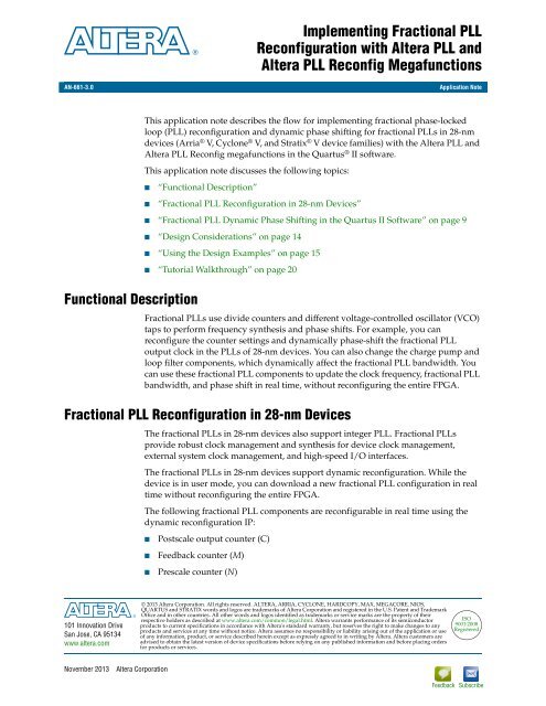
This application note describes the flow for implementing fractional phase-locked<br />
loop (<strong>PLL</strong>) reconfiguration <strong>and</strong> dynamic phase shifting for fractional <strong>PLL</strong>s in 28-nm<br />
devices (Arria ® V, Cyclone ® V, <strong>and</strong> Stratix ® V device families) <strong>with</strong> the Altera <strong>PLL</strong> <strong>and</strong><br />
Altera <strong>PLL</strong> Reconfig megafunctions in the Quartus ® II software.<br />
This application note discusses the following topics:<br />
■<br />
■<br />
“Functional Description”<br />
“<strong>Fractional</strong> <strong>PLL</strong> <strong>Reconfiguration</strong> in 28-nm Devices”<br />
■ “<strong>Fractional</strong> <strong>PLL</strong> Dynamic Phase Shifting in the Quartus II Software” on page 9<br />
■ “Design Considerations” on page 14<br />
■ “Using the Design Examples” on page 15<br />
■ “Tutorial Walkthrough” on page 20<br />
Functional Description<br />
<strong>Fractional</strong> <strong>PLL</strong>s use divide counters <strong>and</strong> different voltage-controlled oscillator (VCO)<br />
taps to perform frequency synthesis <strong>and</strong> phase shifts. For example, you can<br />
reconfigure the counter settings <strong>and</strong> dynamically phase-shift the fractional <strong>PLL</strong><br />
output clock in the <strong>PLL</strong>s of 28-nm devices. You can also change the charge pump <strong>and</strong><br />
loop filter components, which dynamically affect the fractional <strong>PLL</strong> b<strong>and</strong>width. You<br />
can use these fractional <strong>PLL</strong> components to update the clock frequency, fractional <strong>PLL</strong><br />
b<strong>and</strong>width, <strong>and</strong> phase shift in real time, <strong>with</strong>out reconfiguring the entire FPGA.<br />
<strong>Fractional</strong> <strong>PLL</strong> <strong>Reconfiguration</strong> in 28-nm Devices<br />
The fractional <strong>PLL</strong>s in 28-nm devices also support integer <strong>PLL</strong>. <strong>Fractional</strong> <strong>PLL</strong>s<br />
provide robust clock management <strong>and</strong> synthesis for device clock management,<br />
external system clock management, <strong>and</strong> high-speed I/O interfaces.<br />
The fractional <strong>PLL</strong>s in 28-nm devices support dynamic reconfiguration. While the<br />
device is in user mode, you can download a new fractional <strong>PLL</strong> configuration in real<br />
time <strong>with</strong>out reconfiguring the entire FPGA.<br />
The following fractional <strong>PLL</strong> components are reconfigurable in real time using the<br />
dynamic reconfiguration IP:<br />
■<br />
■<br />
■<br />
Postscale output counter (C)<br />
Feedback counter (M)<br />
Prescale counter (N)<br />
101 Innovation Drive<br />
San Jose, CA 95134<br />
www.altera.com<br />
© 2013 Altera Corporation. All rights reserved. <strong>ALTERA</strong>, ARRIA, CYCLONE, HARDCOPY, MAX, MEGACORE, NIOS,<br />
QUARTUS <strong>and</strong> STRATIX words <strong>and</strong> logos are trademarks of Altera Corporation <strong>and</strong> registered in the U.S. Patent <strong>and</strong> Trademark<br />
Office <strong>and</strong> in other countries. All other words <strong>and</strong> logos identified as trademarks or service marks are the property of their<br />
respective holders as described at www.altera.com/common/legal.html. Altera warrants performance of its semiconductor<br />
products to current specifications in accordance <strong>with</strong> Altera's st<strong>and</strong>ard warranty, but reserves the right to make changes to any<br />
products <strong>and</strong> services at any time <strong>with</strong>out notice. Altera assumes no responsibility or liability arising out of the application or use<br />
of any information, product, or service described herein except as expressly agreed to in writing by Altera. Altera customers are<br />
advised to obtain the latest version of device specifications before relying on any published information <strong>and</strong> before placing orders<br />
for products or services.<br />
ISO<br />
9001:2008<br />
Registered<br />
November 2013<br />
Altera Corporation<br />
Feedback Subscribe
Page 2<br />
<strong>Fractional</strong> <strong>PLL</strong> <strong>Reconfiguration</strong> in 28-nm Devices<br />
■ Charge-pump current (I CP ), <strong>and</strong> loop-filter components (R, C)<br />
1 The Quartus II software version 12.0 supports I CP , R <strong>and</strong> C reconfiguration.<br />
■<br />
■<br />
Dynamic phase shifting of each counter<br />
<strong>Fractional</strong> division (M FRAC ) for Delta Sigma Modulator (DSM)<br />
Applications that operate at multiple frequencies can benefit from fractional <strong>PLL</strong><br />
reconfiguration in real time. <strong>Fractional</strong> <strong>PLL</strong> reconfiguration is also beneficial in<br />
prototyping environments, allowing you to sweep fractional <strong>PLL</strong> output frequencies<br />
<strong>and</strong> adjusting the clock output phase at any stage of your design. You can also use this<br />
feature to adjust clock-to-out (t CO ) delays in real time by changing the output clock<br />
phase shift.<br />
<strong>Implementing</strong> <strong>Fractional</strong> <strong>PLL</strong> <strong>Reconfiguration</strong> on 28-nm Devices Using the<br />
Quartus II Software<br />
You can use the Altera <strong>PLL</strong> Reconfig MegaWizard ® Plug-In Manager to enable<br />
reconfiguration circuitry in the Altera Phase-Locked Loop (Altera <strong>PLL</strong>) megafunction<br />
instantiation in your design. The Altera <strong>PLL</strong> Reconfig megafunction simplifies the<br />
fractional <strong>PLL</strong>s reconfiguration process.<br />
The Altera <strong>PLL</strong> Reconfig megafunction interacts <strong>with</strong> a user control logic <strong>and</strong> a bus<br />
that connects directly to the Altera <strong>PLL</strong> instance using the Avalon Memory-Mapped<br />
(Avalon-MM) interface.<br />
Figure 1 shows the connection between the Altera <strong>PLL</strong> <strong>and</strong> the Altera <strong>PLL</strong> Reconfig<br />
megafunctions.<br />
Figure 1. Altera <strong>PLL</strong> Reconfig <strong>and</strong> Altera <strong>PLL</strong> Megafunctions in the Quartus II Software<br />
<strong>Implementing</strong> <strong>Fractional</strong> <strong>PLL</strong> <strong>Reconfiguration</strong> <strong>with</strong> Altera <strong>PLL</strong> <strong>and</strong> Altera <strong>PLL</strong> Reconfig<br />
Megafunctions<br />
November 2013<br />
Altera Corporation
<strong>Fractional</strong> <strong>PLL</strong> <strong>Reconfiguration</strong> in 28-nm Devices Page 3<br />
To connect the Altera <strong>PLL</strong> <strong>and</strong> Altera <strong>PLL</strong> Reconfig instances in your design, follow<br />
these steps:<br />
1. Connect the reconfig_to_pll[63:0] bus on the Altera <strong>PLL</strong> Reconfig instance to<br />
the reconfig_to_pll[63:0] bus on the Altera <strong>PLL</strong> instance.<br />
2. Connect the reconfig_from_pll[63:0] bus on the Altera <strong>PLL</strong> instance to the<br />
reconfig_from_pll[63:0] bus on the Altera <strong>PLL</strong> Reconfig instance.<br />
3. Connect the mgmt_clk signal to a clock source. The mgmt_clk signal can be a free<br />
running clock, eliminating the need to control the start <strong>and</strong> stop of the mgmt_clk<br />
signal.<br />
4. To perform Avalon read or write operations, connect the mgmt_reset,<br />
mgmt_read_data[31:0], mgmt_write, mgmt_address[5:0], mgmt_write_data[31:0]<br />
buses, <strong>and</strong> the mgmt_wait_request <strong>and</strong> mgmt_read signals to user control logic.<br />
Control Interface<br />
The control interface for the Altera <strong>PLL</strong> Reconfig megafunction is an Avalon-MM<br />
slave interface, which the master user logic controls. External user logic uses these<br />
Avalon ports to reconfigure the fractional <strong>PLL</strong> settings directly.<br />
Table 1 lists the Avalon-MM signals in the Altera <strong>PLL</strong> Reconfig megafunction. Logic<br />
are sampled <strong>with</strong> rising edge of the clock. The first rising edge after deassertion of the<br />
waitrequest signal will sample a read/write comm<strong>and</strong>.<br />
Table 1. Avalon-MM Signals in the Altera <strong>PLL</strong> Reconfig Megafunction<br />
mgmt_read_data[31:0]<br />
mgmt_write_data[31:0]<br />
mgmt_address[5:0]<br />
mgmt_read<br />
mgmt_write<br />
mgmt_reset<br />
mgmt_waitrequest<br />
Port Direction Description<br />
Output<br />
Input<br />
Input<br />
Input<br />
Input<br />
Input<br />
Output<br />
Data read from the Altera <strong>PLL</strong> Reconfig megafunction<br />
when you assert the mgmt_read signal.<br />
Data written to the Altera <strong>PLL</strong> Reconfig megafunction<br />
when you assert the mgmt_write signal.<br />
Specifies the address of the memory mapped register<br />
for a read or write operation.<br />
Active high signal. Asserted to indicate a read operation.<br />
When present, read data is available on the<br />
mgmt_read_data bus.<br />
Active high signal. Asserted to indicate a write<br />
operation. When present, the mgmt_write_data bus<br />
requires write data.<br />
Active-high signal that resets all <strong>PLL</strong> counters to their<br />
initial values. When this signal is driven high, the <strong>PLL</strong><br />
resets its counters, clears the <strong>PLL</strong> outputs, <strong>and</strong> loses<br />
lock. After this signal goes low again, the lock process<br />
begins <strong>and</strong> the <strong>PLL</strong> resynchronizes to its input reference<br />
clock.<br />
Active high signal. When the <strong>ALTERA</strong>_<strong>PLL</strong>_RECONFIG<br />
megafunction asserts this signal it will ignore read or<br />
write operations.<br />
November 2013<br />
Altera Corporation<br />
<strong>Implementing</strong> <strong>Fractional</strong> <strong>PLL</strong> <strong>Reconfiguration</strong> <strong>with</strong> Altera <strong>PLL</strong> <strong>and</strong> Altera <strong>PLL</strong> Reconfig<br />
Megafunctions
Page 4<br />
<strong>Fractional</strong> <strong>PLL</strong> <strong>Reconfiguration</strong> in 28-nm Devices<br />
Table 2 lists the fractional <strong>PLL</strong> dynamic reconfiguration registers <strong>and</strong> settings.<br />
Table 2. <strong>Fractional</strong> <strong>PLL</strong> Dynamic <strong>Reconfiguration</strong> <strong>and</strong> Status Register (Part 1 of 2)<br />
Register Name<br />
Register Size<br />
Address (Binary)<br />
Counter Bit Settings<br />
Read/Write<br />
Mode Register 1 000000<br />
■ Write 0 for waitrequest mode<br />
■<br />
Write 1 for polling mode<br />
Status Register 1 000001 ■ 0 = busy<br />
Read<br />
■ 1 = ready<br />
Start Register 1 000010 Write either 0 or 1 to start fractional <strong>PLL</strong> reconfiguration or dynamic phase shift Write<br />
N Counter 18 000011<br />
M Counter 18 000100<br />
C Counter 23 000101<br />
■<br />
■<br />
■<br />
N_counter[7:0] = low_count<br />
N_counter[15:8] = high_count<br />
Total_div = high_count + low_count<br />
■ N_counter[16] = bypass enable (3)<br />
■<br />
■<br />
N_counter[16] = 0, f REF =f IN /Total_div<br />
N_counter[16] = 1, f REF =f IN (N counter is bypassed)<br />
■ N_counter[17] = odd division (3)<br />
■<br />
■<br />
■<br />
■<br />
■<br />
N_counter[17] = 0, even division, duty cycle = high_count/Total_div<br />
N_counter[17] = 1, odd division, duty cycle = (high_count-0.5)/Total_div<br />
M_counter[7:0] = low_count<br />
M_counter[15:8] = high_count<br />
Total_div = high_count + low_count<br />
■ M_counter[16] = bypass enable (3)<br />
■<br />
■<br />
M_counter[16] = 0, f FB =f VCO /Total_div<br />
M_counter[16] = 1, f FB =f VCO (M counter is bypassed)<br />
■ M_counter[17] = odd division (3)<br />
■<br />
■<br />
■<br />
■<br />
■<br />
M_counter[17] = 0, even division, duty cycle = high_count/Total_div<br />
M_counter[17] = 1, odd division, duty cycle = (high_count-0.5)/Total_div<br />
C_counter[7:0] = low_count<br />
C_counter[15:8] = high_count<br />
Total_div = high_count + low_count<br />
■ C_counter[16] = bypass enable (3)<br />
■<br />
■<br />
C_counter[16] = 0, f OUT =f VCO /Total_div<br />
C_counter[16] = 1, f OUT =f VCO (C counter is bypassed)<br />
■ C_counter[17] = odd division (3)<br />
■<br />
■<br />
C_counter[17] = 0, even division, duty cycle = high_count/Total_div<br />
C_counter[17] = 1, odd division, duty cycle = (high_count-0.5)/Total_div<br />
■ C_counter[22:18] is a five bit binary number ranging from 00000 to 10001<br />
(0 -17) to select which C counter to change. For example, if you want to change<br />
C2, set C_counter[18:22] to 00010.<br />
Read/Write<br />
Read/Write<br />
Read/Write<br />
Read/Write<br />
(2)<br />
<strong>Implementing</strong> <strong>Fractional</strong> <strong>PLL</strong> <strong>Reconfiguration</strong> <strong>with</strong> Altera <strong>PLL</strong> <strong>and</strong> Altera <strong>PLL</strong> Reconfig<br />
Megafunctions<br />
November 2013<br />
Altera Corporation
<strong>Fractional</strong> <strong>PLL</strong> <strong>Reconfiguration</strong> in 28-nm Devices Page 5<br />
Table 2. <strong>Fractional</strong> <strong>PLL</strong> Dynamic <strong>Reconfiguration</strong> <strong>and</strong> Status Register (Part 2 of 2)<br />
Register Name<br />
Register Size<br />
Address (Binary)<br />
Counter Bit Settings<br />
Read/Write<br />
Dynamic_Phase<br />
_Shift<br />
M Counter<br />
<strong>Fractional</strong> Value<br />
(K)<br />
B<strong>and</strong>width<br />
Setting<br />
Charge Pump<br />
Setting<br />
VCO DIV<br />
Setting<br />
MIF Base<br />
Address<br />
22 000110<br />
32 000111<br />
4 001000<br />
3 001001<br />
1 011100<br />
■<br />
■<br />
■<br />
Dynamic_Phase_Shift[15:0] = number of shifts<br />
■ Number of shifts = the number of times you want to shift the output clock.<br />
Every time you perform a shift, the actual amount of shift is 1/8 of the VCO<br />
period. For example, if the VCO is running at 1.6 GHz, each phase shift equals to<br />
78.125 ps.<br />
Dynamic_Phase_Shift[20:16] = cnt_select.<br />
■ cnt_select is a five bit value that specifies which counter output is shifted.<br />
For more information about cnt_select mapping, refer to Table 4.<br />
Dynamic_Phase_Shift[21] = up_dn<br />
■<br />
■<br />
■<br />
up_dn = The direction of the shift.<br />
up_dn = 1 (positive phase shift).<br />
up_dn = 0 (negative phase shift).<br />
<strong>Fractional</strong> part of the M counter (for DSM). The actual fractional values are:<br />
Write<br />
■ M FRAC = K[X:0]/2 X (X=8, 16, 24 or 32) (1)<br />
Write<br />
■ M counter final value = Total_div for M Counter + M FRAC<br />
For the b<strong>and</strong>width settings, refer to the <strong>PLL</strong> <strong>Reconfiguration</strong> Calculator. You can<br />
download the <strong>PLL</strong> <strong>Reconfiguration</strong> Calculator from the Documentation: Application<br />
Notes page on the Altera website.<br />
For the charge pump settings, refer to the <strong>PLL</strong> <strong>Reconfiguration</strong> Calculator. You can<br />
download the <strong>PLL</strong> <strong>Reconfiguration</strong> Calculator from the Documentation: Application<br />
Notes page on the Altera website.<br />
Enable or disable /2 divider for VCO to keep VCO frequency in operating range.<br />
■ 0: VCO DIV = 1<br />
■ 1: VCO DIV = 2<br />
9 011111 Base address for the start of a <strong>PLL</strong> profile in a .mif. Write<br />
Read/Write<br />
Read/Write<br />
Read/Write<br />
Notes to Table 2:<br />
(1) K counter reconfiguration is effective only when you configure the <strong>PLL</strong> in fractional mode prior to reconfiguration. For optimum performance, set the M FRAC<br />
value between 0.05 <strong>and</strong> 0.95. X = fractional carry bit, determined in the Altera <strong>PLL</strong> MegaWizard. The default value for X is 24 <strong>and</strong> cannot be reconfigured<br />
during <strong>PLL</strong> reconfiguration.<br />
(2) For C counter read operation, use the address for the selected counter in Table 3.<br />
(3) The bypass enable bit, even division bit, <strong>and</strong> odd division bit of the M, N, C counters support write operation only.<br />
November 2013<br />
Altera Corporation<br />
<strong>Implementing</strong> <strong>Fractional</strong> <strong>PLL</strong> <strong>Reconfiguration</strong> <strong>with</strong> Altera <strong>PLL</strong> <strong>and</strong> Altera <strong>PLL</strong> Reconfig<br />
Megafunctions
Page 6<br />
<strong>Fractional</strong> <strong>PLL</strong> <strong>Reconfiguration</strong> in 28-nm Devices<br />
Table 3 lists the corresponding address for selected counter during read operation.<br />
Table 3. Corresponding Address for Selected Counter During Read Operation<br />
Address (Binary) Selected Counter Counter Bit Setting<br />
001010 Counter C0<br />
001011 Counter C1<br />
001100 Counter C2<br />
001101 Counter C3<br />
001110 Counter C4<br />
001111 Counter C5<br />
010000 Counter C6<br />
010001 Counter C7<br />
■ C_counter[7:0] = low_count<br />
010010 Counter C8<br />
■ C_counter[15:8] = high_count<br />
010011 Counter C9<br />
■ Total_div=high_count+low_count<br />
010100 Counter C10<br />
010101 Counter C11<br />
010110 Counter C12<br />
010111 Counter C13<br />
011000 Counter C14<br />
011001 Counter C15<br />
011010 Counter C16<br />
011011 Counter C17<br />
Table 4 lists the mapping of the cnt_select (Dynamic_Phase_Shift[20:16]) <strong>and</strong> the<br />
counter for dynamic phase shift.<br />
Table 4. Mapping for cnt_select (Dynamic_Phase_Shift[20:16]) (Part 1 of 2)<br />
Device Family<br />
Dynamic_Phase_Shift[20:16]<br />
Dynamic Phase Shift Selected<br />
Counter<br />
Arria V, Cyclone V, <strong>and</strong> Stratix V 5'b00000 Counter C0<br />
Arria V, Cyclone V, <strong>and</strong> Stratix V 5'b00001 Counter C1<br />
Arria V, Cyclone V, <strong>and</strong> Stratix V 5'b00010 Counter C2<br />
Arria V, Cyclone V, <strong>and</strong> Stratix V 5'b00011 Counter C3<br />
Arria V, Cyclone V, <strong>and</strong> Stratix V 5'b00100 Counter C4<br />
Arria V, Cyclone V, <strong>and</strong> Stratix V 5'b00101 Counter C5<br />
Arria V, Cyclone V, <strong>and</strong> Stratix V 5'b00110 Counter C6<br />
Arria V, Cyclone V, <strong>and</strong> Stratix V 5'b00111 Counter C7<br />
Arria V, Cyclone V, <strong>and</strong> Stratix V 5'b01000 Counter C8<br />
Arria V <strong>and</strong> Stratix V 5'b01001 Counter C9<br />
Arria V <strong>and</strong> Stratix V 5'b01010 Counter C10<br />
Arria V <strong>and</strong> Stratix V 5'b01011 Counter C11<br />
Arria V <strong>and</strong> Stratix V 5'b01100 Counter C12<br />
Arria V <strong>and</strong> Stratix V 5'b01101 Counter C13<br />
<strong>Implementing</strong> <strong>Fractional</strong> <strong>PLL</strong> <strong>Reconfiguration</strong> <strong>with</strong> Altera <strong>PLL</strong> <strong>and</strong> Altera <strong>PLL</strong> Reconfig<br />
Megafunctions<br />
November 2013<br />
Altera Corporation
<strong>Fractional</strong> <strong>PLL</strong> <strong>Reconfiguration</strong> in 28-nm Devices Page 7<br />
Table 4. Mapping for cnt_select (Dynamic_Phase_Shift[20:16]) (Part 2 of 2)<br />
Device Family<br />
Reconfiguring <strong>Fractional</strong> <strong>PLL</strong> Settings<br />
Dynamic_Phase_Shift[20:16]<br />
Dynamic Phase Shift Selected<br />
Counter<br />
Arria V <strong>and</strong> Stratix V 5'b01110 Counter C14<br />
Arria V <strong>and</strong> Stratix V 5'b01111 Counter C15<br />
Arria V <strong>and</strong> Stratix V 5'b10000 Counter C16<br />
Arria V <strong>and</strong> Stratix V 5'b10001 Counter C17<br />
Arria V, Cyclone V, <strong>and</strong> Stratix V 5'b11111 All C Counters<br />
Arria V, Cyclone V, <strong>and</strong> Stratix V 5'b10010 M Counter<br />
You can dynamically reconfigure fractional <strong>PLL</strong>s <strong>with</strong> the Avalon-MM interface. To<br />
perform dynamic reconfiguration, follow these steps:<br />
1. Through an Avalon write operation, write to the mode register a value of 0 or 1 at<br />
the startup of the Altera <strong>PLL</strong> Reconfig megafunction. The mode register<br />
determines whether the Altera <strong>PLL</strong> Reconfig megafunction operates in<br />
waitrequest or polling mode.<br />
2. Specify the element <strong>and</strong> its new value through an Avalon write operation. For<br />
more information about the address for each reconfigurable element, refer to<br />
Table 2 on page 4 <strong>and</strong> Table 4 on page 6.<br />
3. Repeat Step 2 for all the reconfigurable elements (N, M, C counters, M FRAC value<br />
<strong>and</strong> others) that you want to change.<br />
4. Through an Avalon write operation, write either 0 or 1 to the start register. Writing<br />
to the start register triggers the dynamic reconfiguration, the dynamic phase shift,<br />
or both:<br />
a. If you set the mode register to 0 (waitrequest mode) in Step 1, the Altera <strong>PLL</strong><br />
Reconfig megafunction asserts the mgmt_waitrequest signal until after the<br />
reconfiguration. You can only perform another Avalon read or write operation<br />
after the Altera <strong>PLL</strong> Reconfig megafunction deasserts the mgmt_waitrequest<br />
signal, or<br />
b. If you set the mode register to 1 (polling mode) in Step 1, the Altera <strong>PLL</strong><br />
Reconfig megafunction writes 0 (busy) to the status register. You can poll bit 0<br />
of the status register periodically by performing Avalon read operations to<br />
ensure that the reconfiguration is complete. The Altera <strong>PLL</strong> Reconfig<br />
megafunction ignores any new reconfiguration instructions (Avalon write<br />
operations) until a value of 1 has been read from the status register.<br />
1 Lock the fractional <strong>PLL</strong> to the reference clock before you perform the dynamic<br />
reconfiguration or the dynamic phase shifting.<br />
November 2013<br />
Altera Corporation<br />
<strong>Implementing</strong> <strong>Fractional</strong> <strong>PLL</strong> <strong>Reconfiguration</strong> <strong>with</strong> Altera <strong>PLL</strong> <strong>and</strong> Altera <strong>PLL</strong> Reconfig<br />
Megafunctions
Page 8<br />
<strong>Fractional</strong> <strong>PLL</strong> <strong>Reconfiguration</strong> in 28-nm Devices<br />
Figure 2 shows a waveform example for performing dynamic reconfiguration in<br />
reconfiguring M, M FRAC , N <strong>and</strong> C counters.<br />
Figure 2. Waveform Example for Performing Dynamic <strong>Reconfiguration</strong> in Reconfiguring M, MFRAC, N <strong>and</strong> C counters<br />
mgmt_clk<br />
mgmt_address[5:0]<br />
00h 04h 07h 03h<br />
05h<br />
08h 09h 02h<br />
01h<br />
mgmt_writedata[31:0]<br />
00000001h 00001212h 00444444h 00000202h 00000303h 00040404h<br />
a b c d e f<br />
00000006h 00000003h 00000001h<br />
g h i<br />
don’t care<br />
mgmt_write<br />
mgmt_read<br />
j<br />
mgmt_readdata[31:0]<br />
00000000h<br />
00000001h<br />
The following list describes the operation in Figure 2:<br />
a. Avalon-MM writes to the mode register (address = 0x00) to set the Altera <strong>PLL</strong><br />
Reconfig megafunction to operate in polling mode.<br />
b. Avalon-MM writes to the M counter register (address = 0x04) to reconfigure the<br />
M counter to 36.<br />
c. Avalon-MM writes to the M counter <strong>Fractional</strong> Value (K) register (address =<br />
0x07) to reconfigure M FRAC to 0.2665 (decimal value).<br />
d. Avalon-MM writes to the N counter register (address = 0x03) to reconfigure the<br />
N counter to 4.<br />
e. Avalon-MM writes to the C counter register (address=0x05) to reconfigure the<br />
C0 counter to 8 (high_count =3, low_count=3, even division).<br />
f. Avalon-MM writes to the C counter register (address=0x05) to reconfigure the<br />
C1 counter to 8 (high_count =4, low_count=4, even division).<br />
g. Avalon-MM writes to the b<strong>and</strong>width setting register (address=0x08) to<br />
reconfigure the b<strong>and</strong>width setting to medium b<strong>and</strong>width.<br />
h. Avalon-MM writes to the charge pump setting register (address=0x09) to<br />
reconfigure the charge pump setting to medium b<strong>and</strong>width.<br />
i. Avalon-MM writes to the start register (address = 0x02) to start the<br />
reconfiguration.<br />
j. Avalon-MM reads from the status register (address = 0x01) until a value of 1 is<br />
read from the status register, indicating a successful reconfiguration.<br />
<strong>Implementing</strong> <strong>Fractional</strong> <strong>PLL</strong> <strong>Reconfiguration</strong> <strong>with</strong> Altera <strong>PLL</strong> <strong>and</strong> Altera <strong>PLL</strong> Reconfig<br />
Megafunctions<br />
November 2013<br />
Altera Corporation
<strong>Fractional</strong> <strong>PLL</strong> Dynamic Phase Shifting in the Quartus II Software Page 9<br />
<strong>Fractional</strong> <strong>PLL</strong> Dynamic Phase Shifting in the Quartus II Software<br />
The dynamic phase shifting feature allows the output phases of individual fractional<br />
<strong>PLL</strong> outputs to be dynamically adjusted relative to each other <strong>and</strong> to the reference<br />
clock. The smallest incremental step equals to 1/8th of the VCO period. The output<br />
clocks are active during this dynamic phase-shift process.<br />
You can use the following methods to perform dynamic phase shifting:<br />
■<br />
■<br />
the Altera <strong>PLL</strong> Reconfig megafunction<br />
the dynamic phase-shifting circuitry using the Altera <strong>PLL</strong> megafunction directly.<br />
1 In the Quartus II software version 11.1 sp2, you can only perform dynamic<br />
phase shifting using the Altera <strong>PLL</strong> Reconfig megafunction. However, you<br />
can perform dynamic phase shifting directly using the Altera <strong>PLL</strong><br />
megafunction beginning from the Quartus II software version 12.0<br />
onwards.<br />
Performing Dynamic Phase Shifting <strong>with</strong> the Altera <strong>PLL</strong> Megafunction<br />
Figure 3. Dynamic Phase Shift Waveform<br />
You can directly perform dynamic phase shift by enabling the dynamic phase shift<br />
ports.<br />
To perform one dynamic phase shift, follow these steps:<br />
1. Set the updn <strong>and</strong> cntsel ports.<br />
2. Assert the phase_en port for at least two scanclk cycles. Each phase_en pulse<br />
enables one phase shift.<br />
3. Deassert the phase_en port after phase_done goes low.<br />
The updn, cntsel, <strong>and</strong> phase_en ports are synchronous to scanclk. The phase_done<br />
signal going low is synchronous to the scanclk signal, but it is asynchronous to the<br />
scanclk signal when going high. Depending on the VCO <strong>and</strong> scanclk frequencies, the<br />
low time of the phase_done port may be greater than or less than one scanclk cycle.<br />
Each phase_en pulse enables one phase shift. If you want to perform multiple phase<br />
shifts, you must assert the phase_en signal multiple times. The phase_en signal must<br />
only be asserted after the phase_done signal goes from low to high.<br />
Figure 3 shows the waveform for dynamic phase shift.<br />
clk<br />
updn<br />
a<br />
cntsel<br />
00h<br />
01h<br />
00h<br />
phase_en<br />
b c d e<br />
phase_done<br />
November 2013<br />
Altera Corporation<br />
<strong>Implementing</strong> <strong>Fractional</strong> <strong>PLL</strong> <strong>Reconfiguration</strong> <strong>with</strong> Altera <strong>PLL</strong> <strong>and</strong> Altera <strong>PLL</strong> Reconfig<br />
Megafunctions
Page 10<br />
<strong>Fractional</strong> <strong>PLL</strong> Dynamic Phase Shifting in the Quartus II Software<br />
The following list describes the operation in Figure 3:<br />
a. Set the cntsel port to logical counter C1 <strong>and</strong> the updn port to positive phase<br />
shift direction.<br />
b. Assert the phase_en port to begin the first phase shift operation on logical<br />
counter C1.<br />
c. Deassert the phase_en port after phase_done goes low.<br />
d. Assert the phase_en port again to begin the second phase shift operation.<br />
e. Deassert the phase_en port after phase_down goes low.<br />
Table 5. Dynamic Phase Shift Signals in the Altera <strong>PLL</strong> Megafunction<br />
Port Direction Description<br />
phase_en<br />
scanclk<br />
updn<br />
cntsel<br />
phase_done<br />
Note to Table 5:<br />
Input<br />
Input<br />
Input<br />
Input<br />
Output<br />
Transition from low to high enables dynamic phase shifting, one phase shift per transition<br />
from low to high.<br />
Free running clock from the core in combination <strong>with</strong> phase_en to enable <strong>and</strong> disable<br />
dynamic phase shifting.<br />
Selects dynamic phase shift direction; 1 = positive phase shift; 0 = negative phase shift. The<br />
<strong>PLL</strong> registers the signal on the rising edge of scanclk.<br />
Logical Counter Select (1) . Five bits decoded to select one of the C counters for phase<br />
adjustment. The <strong>PLL</strong> registers the signal on the rising edge of scanclk.<br />
When asserted, this port informs the core-logic that the phase adjustment is complete <strong>and</strong><br />
the <strong>PLL</strong> is ready to act on a possible next adjustment pulse. Asserts based on internal <strong>PLL</strong><br />
timing. Deasserts on the rising edge of scanclk.<br />
(1) For the corresponding address of a selected logical counter, refer to Table 6.<br />
Table 6. Logical Counter Location in <strong>PLL</strong> (Part 1 of 2)<br />
cntsel[4:0]<br />
5'b00000<br />
5b'00001<br />
5'b00010<br />
5'b00011<br />
5'b00100<br />
5'b00101<br />
5'b00110<br />
5'b00111<br />
5'b01000<br />
5'b01001<br />
5'b01010<br />
5'b01011<br />
Selected Logical Counter<br />
Logical counter C0<br />
Logical counter C1<br />
Logical counter C2<br />
Logical counter C3<br />
Logical counter C4<br />
Logical counter C5<br />
Logical counter C6<br />
Logical counter C7<br />
Logical counter C8<br />
Logical counter C9<br />
Logical counter C10<br />
Logical counter C11<br />
<strong>Implementing</strong> <strong>Fractional</strong> <strong>PLL</strong> <strong>Reconfiguration</strong> <strong>with</strong> Altera <strong>PLL</strong> <strong>and</strong> Altera <strong>PLL</strong> Reconfig<br />
Megafunctions<br />
November 2013<br />
Altera Corporation
<strong>Fractional</strong> <strong>PLL</strong> Dynamic Phase Shifting in the Quartus II Software Page 11<br />
Table 6. Logical Counter Location in <strong>PLL</strong> (Part 2 of 2)<br />
cntsel[4:0]<br />
5'b01100<br />
5'b01101<br />
5'b01110<br />
5'b01111<br />
5'b10000<br />
5'b10001<br />
Selected Logical Counter<br />
Logical counter C12<br />
Logical counter C13<br />
Logical counter C14<br />
Logical counter C15<br />
Logical counter C16<br />
Logical counter C17<br />
Performing Dynamic Phase Shifting <strong>with</strong> the Altera <strong>PLL</strong> Reconfig<br />
Megafunction<br />
To perform dynamic phase shifting, follow Steps 1-4 in “Reconfiguring <strong>Fractional</strong> <strong>PLL</strong><br />
Settings”, except in Step 2, you only need to write to the Dynamic_Phase_Shift<br />
register.<br />
c<br />
If you assert the areset signal to fractional <strong>PLL</strong> after the dynamic phase shift, you lose<br />
all successful phase adjustment <strong>with</strong> dynamic phase shift in user mode.<br />
Figure 4 shows a waveform example for performing dynamic phase shifting.<br />
Figure 4. Waveform Example for Performing Dynamic Phase Shifting<br />
mgmt_clk<br />
mgmt_address[5:0]<br />
00h 06h 02h<br />
01h<br />
mgmt_writedata[31:0]<br />
00000001h 00210004h 00000001h<br />
don’t care<br />
mgmt_write<br />
a b c<br />
d<br />
mgmt_read<br />
mgmt_readdata[31:0]<br />
don’t care<br />
0000000h<br />
00000001h<br />
The following list describes the operations in Figure 4:<br />
a. Avalon writes to the mode register (address=0x00) to set the Altera <strong>PLL</strong><br />
Reconfig megafunction to operate in polling mode.<br />
b. Avalon writes to the dynamic phase shift register (address=0x06) to perform<br />
dynamic phase shift on C1 counter for four steps forward.<br />
c. Avalon writes to the start register (address=0x02) to start dynamic phase<br />
shifting.<br />
d. Avalon reads from the status register (address=0x01) until a value of 1 has been<br />
read from the status register, indicating the dynamic phase shifting is complete.<br />
November 2013<br />
Altera Corporation<br />
<strong>Implementing</strong> <strong>Fractional</strong> <strong>PLL</strong> <strong>Reconfiguration</strong> <strong>with</strong> Altera <strong>PLL</strong> <strong>and</strong> Altera <strong>PLL</strong> Reconfig<br />
Megafunctions
Page 12<br />
MIF Streaming<br />
MIF Streaming<br />
MIF streaming allows you to dynamically reconfigure <strong>PLL</strong>s through the Altera <strong>PLL</strong><br />
Reconfig megafunction using predefined settings saved in an on-chip RAM.<br />
To start reconfiguration via MIF:<br />
1. Write the base address in the ROM where the .mif of the <strong>PLL</strong> is located. You can<br />
have multiple .mif files in a ROM. You just need to use a different address location<br />
in the ROM for another .mif streaming.The following lists the details:<br />
■<br />
Writedata = base address in ROM.<br />
■ Write address = MIF address (011111).<br />
2. Write to the START register to begin.<br />
3. The Altera <strong>PLL</strong> Reconfig megafunction then starts reading the .mif for new<br />
settings <strong>and</strong> values, changing the <strong>PLL</strong> accordingly.<br />
4. The Altera <strong>PLL</strong> Reconfig megafunction generates signals when all changes are<br />
done <strong>and</strong> <strong>PLL</strong> is locked.<br />
MIF streaming is a subsystem generated in the Altera <strong>PLL</strong> Reconfig megafunction. If<br />
you set the Enable MIF Streaming option to 0, MIF streaming is not generated <strong>and</strong><br />
the top level module's ports map directly to the core. If you set the Enable MIF<br />
Streaming option to 1, the MIF reader is instantiated in the top-level of the Altera <strong>PLL</strong><br />
Reconfig module as shown in Figure 5:<br />
Figure 5. Altera <strong>PLL</strong> Reconfig <strong>with</strong> MIF Streaming Enabled<br />
<strong>ALTERA</strong>_<strong>PLL</strong>_RECONFIG Top<br />
addr<br />
write<br />
writedata<br />
read<br />
readdata<br />
waitrequest<br />
MIF Reader<br />
busy<br />
M20K<br />
addr<br />
write<br />
writedata<br />
read<br />
readdata<br />
waitrequest<br />
mif_start<br />
mif_base_addr<br />
addr<br />
write<br />
writedata<br />
read<br />
readdata<br />
waitrequest<br />
mif_start<br />
mif_base_addr<br />
<strong>ALTERA</strong>_<strong>PLL</strong>_RECONFIG Core<br />
Internal Registers<br />
N<br />
M<br />
C<br />
...<br />
...<br />
...<br />
MIF Addr<br />
To/From <strong>PLL</strong><br />
When you write to the MIF Base Address register <strong>and</strong> starts the MIF streaming<br />
operation, the Altera <strong>PLL</strong> Reconfig megafunction signals the MIF reader to begin the<br />
operation. Waitrequest is asserted until the operation is complete.<br />
<strong>Implementing</strong> <strong>Fractional</strong> <strong>PLL</strong> <strong>Reconfiguration</strong> <strong>with</strong> Altera <strong>PLL</strong> <strong>and</strong> Altera <strong>PLL</strong> Reconfig<br />
Megafunctions<br />
November 2013<br />
Altera Corporation
MIF Streaming Page 13<br />
MIF File Format<br />
MIF streaming switches the Altera <strong>PLL</strong> Reconfig core to waitrequest mode <strong>and</strong> asserts<br />
this signal until the core completed the operation. At this point, MIF streaming<br />
restores the previous mode (waitrequest or polling), unless it is explicitly changed by<br />
the .mif.<br />
The .mif stores the comm<strong>and</strong>s that you want to send to the Altera <strong>PLL</strong> Reconfig<br />
megafunction. MIF streaming then simulates the comm<strong>and</strong>s the user logic would<br />
otherwise send to the Altera <strong>PLL</strong> Reconfig megafunction. These comm<strong>and</strong>s are<br />
address/data pairs in the .mif specifying which setting should be reconfigured to the<br />
new value. Addresses are stored as opcodes in the lower 6 bits of each entry word.<br />
Table 7. Single MIF file for <strong>PLL</strong> <strong>Reconfiguration</strong><br />
31 5 0 MIF_BASE_ADDR<br />
RSVD<br />
Opcode=SOM<br />
RSVD<br />
Opcode=M_counter<br />
DATA M_counter<br />
RSVD<br />
Opcode=N_counter<br />
DATA N_counter<br />
Opcode=B<strong>and</strong><strong>with</strong><br />
DATA B<strong>and</strong>width<br />
...<br />
...<br />
RSVD<br />
Opcode=EOM<br />
Table 8.<br />
Each .mif must be indicated <strong>with</strong> a Start of MIF (SOM) <strong>and</strong> End of MIF (EOM):<br />
Opcode Name Opcode ID Description<br />
Start of MIF (SOM) 111110 Indicate start of single <strong>PLL</strong> configuration<br />
End of MIF (EOM) 111111 Indicate end of single <strong>PLL</strong> configuration<br />
The remaining opcodes are the addresses for each of the registers in the Altera <strong>PLL</strong><br />
Reconfig megafunction.<br />
Multiple <strong>PLL</strong> configurations can be saved in a .mif if appropriately marked by SOM<br />
or EOM. The MIF reader reads the settings from an M20K RAM block, which has<br />
default address width = 9 bits, data width = 32 bits (total words = 512). These sizes can<br />
be changed as parameters are passed to the top-level module; however, data width<br />
must be 32 bits to match the Altera <strong>PLL</strong> Reconfig megafunction.<br />
The M20K is initialized by MIF_FILE_NAME, also a top-level parameter. On the start<br />
of MIF streaming operation, the MIF reader checks the MIF base address in the M20K<br />
RAM block for a SOM opcode. The MIF reader continues to read the file until EOM is<br />
reached.<br />
You can generate a .mif independently <strong>with</strong> a <strong>PLL</strong> MIF configuration file generated<br />
by the Altera <strong>PLL</strong> Megawizard, which stores the entire <strong>PLL</strong> profile.<br />
November 2013<br />
Altera Corporation<br />
<strong>Implementing</strong> <strong>Fractional</strong> <strong>PLL</strong> <strong>Reconfiguration</strong> <strong>with</strong> Altera <strong>PLL</strong> <strong>and</strong> Altera <strong>PLL</strong> Reconfig<br />
Megafunctions
Page 14<br />
Design Considerations<br />
You can also construct you own .mif files by stitching together existing .mif or writing<br />
your own comm<strong>and</strong>s (following the .mif syntax). This allows what settings are stored<br />
in the M20K for future reconfiguration.<br />
Design Considerations<br />
You must consider the following information when using fractional <strong>PLL</strong><br />
reconfiguration:<br />
■<br />
■<br />
■<br />
Changing prescale <strong>and</strong> feedback counter settings (M, N, M FRAC ), charge<br />
pump/loop filter settings affects the fractional <strong>PLL</strong> VCO frequency, which might<br />
require the fractional <strong>PLL</strong> to relock to the reference clock.<br />
Changing the M counter phase shift setting changes the phase relationship of the<br />
output clocks <strong>with</strong> respect to the fractional <strong>PLL</strong> reference clock, which also<br />
requires the fractional <strong>PLL</strong> to relock. Although the exact effect of changing<br />
prescale <strong>and</strong> feedback counter settings (M, N) depends on the changes to the<br />
settings, any changes require relocking.<br />
Adding phase shift using the M counter phase shift setting pulls in all the<br />
fractional <strong>PLL</strong> clock outputs <strong>with</strong> respect to the reference clock. This effectively<br />
adds a negative phase shift because the M counter is in the feedback path.<br />
■ When making changes to the loop elements (M, N, M FRAC , M counter phase, I cp , R,<br />
C), Altera recommends disabling fractional <strong>PLL</strong> outputs to the logic array using<br />
the clkena signals available on the ALTCLKCTRL megafunction. This<br />
recommendation eliminates the possibility of an over frequency condition<br />
affecting system logic while fractional <strong>PLL</strong> is regaining lock.<br />
■<br />
■<br />
■<br />
■<br />
■<br />
■<br />
■<br />
■<br />
■<br />
Changing the K counter values is only effective if the <strong>PLL</strong> is in fractional mode<br />
before reconfiguration.<br />
Changing postscale counters (C) <strong>and</strong> phase do not affect the fractional <strong>PLL</strong> lock<br />
status or VCO frequency. The resolution of phase shift is a function of VCO<br />
frequency, <strong>with</strong> the smallest incremental step equal to 1/8th of the VCO period.<br />
Because the phase relationship between output clocks is important, Altera<br />
recommends resynchronizing the fractional <strong>PLL</strong> using the areset signal. Using<br />
the areset signal resets all internal fractional <strong>PLL</strong> counters <strong>and</strong> reinitiates the<br />
locking process.<br />
<strong>Fractional</strong> <strong>PLL</strong> reconfiguration interface supports a free running mgmt_clk,<br />
eliminating the need to precisely control the start <strong>and</strong> stop of mgmt_clk.<br />
Changing the M or N counter values affect all the output clock frequencies.<br />
C counters can also be reconfigured individually.<br />
Can perform phase shifting, even if C counter is set to 1 <strong>and</strong> bypass is enabled.<br />
When the <strong>PLL</strong> has two clocks <strong>with</strong> 0 degree initial phase shift between the clocks,<br />
the Fitter synthesizes away the second clock automatically. To prevent the clocks<br />
from merging, Altera recommends manually performing location constraint for<br />
each of the <strong>PLL</strong> output counters which share the same frequency <strong>and</strong> phase shift.<br />
Readback counter operation needs at least three scanclk cycle latency.<br />
<strong>Implementing</strong> <strong>Fractional</strong> <strong>PLL</strong> <strong>Reconfiguration</strong> <strong>with</strong> Altera <strong>PLL</strong> <strong>and</strong> Altera <strong>PLL</strong> Reconfig<br />
Megafunctions<br />
November 2013<br />
Altera Corporation
Using the Design Examples Page 15<br />
■<br />
■<br />
In waitrequest mode, the mgmt_waitrequest signal deasserts when <strong>PLL</strong><br />
reconfiguration is complete. If the <strong>PLL</strong> loses lock after reconfiguration is complete,<br />
assert the mgmt_waitrequest signal again until the <strong>PLL</strong> locks. There may be a brief<br />
period after <strong>PLL</strong> reconfiguration is complete, but before the <strong>PLL</strong> has lost lock,<br />
when the mgmt_waitrequest signal will be de-asserted. Altera recommends<br />
allowing sufficient time for the <strong>PLL</strong> to lock after <strong>PLL</strong> reconfiguration is complete<br />
before performing a new Avalon read or write operation.<br />
In polling mode, the status register changes from 0 (busy) to 1 (ready) when <strong>PLL</strong><br />
reconfiguration is complete. If the <strong>PLL</strong> loses lock after reconfiguration is complete,<br />
the status register is at 0 (busy) until the <strong>PLL</strong> locks. There may be a brief period<br />
after <strong>PLL</strong> reconfiguration is complete, but before the <strong>PLL</strong> has lost lock, when the<br />
status register is at 1 (ready). Altera recommends allowing sufficient time for the<br />
<strong>PLL</strong> to lock after <strong>PLL</strong> reconfiguration is complete before performing a new Avalon<br />
read or write operation.<br />
Using the Design Examples<br />
The following sections describe how to set up <strong>and</strong> use the design examples:<br />
■<br />
■<br />
■<br />
“Installing the Design Examples”<br />
“Software Requirement”<br />
“Design Examples”<br />
Installing the Design Examples<br />
You can download the design examples in this application note from the<br />
Documentation: Application Notes page on the Altera website. For more information<br />
about using the design examples, refer to “Design Examples” on page 16.<br />
Software Requirement<br />
You must install the following software in your PC:<br />
■<br />
■<br />
■<br />
The Quartus II Software, beginning from version 11.1 SP2<br />
MegaCore IP Library, beginning from version 11.1 (installed <strong>with</strong> the Quartus II<br />
software)<br />
The Nios ® II Embedded Design Suite (EDS), beginning from version 11.1 SP2<br />
1 Ensure that you extract the Quartus Archived File (.qar) of the design example.<br />
1 This application note assumes that you install the software in the default locations.<br />
November 2013<br />
Altera Corporation<br />
<strong>Implementing</strong> <strong>Fractional</strong> <strong>PLL</strong> <strong>Reconfiguration</strong> <strong>with</strong> Altera <strong>PLL</strong> <strong>and</strong> Altera <strong>PLL</strong> Reconfig<br />
Megafunctions
Page 16<br />
Using the Design Examples<br />
Design Examples<br />
The following sections describe the design examples for implementing fractional <strong>PLL</strong><br />
dynamic reconfiguration <strong>and</strong> phase shifting using Altera <strong>PLL</strong> <strong>and</strong> Altera <strong>PLL</strong><br />
Reconfig megafunctions.<br />
Design Example 1<br />
The design example uses a 5SGXEA7 device. This design example consists of the<br />
Altera <strong>PLL</strong> <strong>and</strong> Altera <strong>PLL</strong> Reconfig megafunctions. The fractional <strong>PLL</strong> synthesizes<br />
two output clocks of 233.34 MHz, <strong>with</strong> 0 ps <strong>and</strong> 107 ps phase shift on C0 <strong>and</strong> C1<br />
output respectively. The input reference clock to the fractional <strong>PLL</strong> is 100 MHz.<br />
The Altera <strong>PLL</strong> Reconfig megafunction connects to a state machine to perform the<br />
required Avalon write <strong>and</strong> read operations. A low pulse on the reset_SM pin starts the<br />
Avalon write <strong>and</strong> read sequence. After reconfiguration, the fractional <strong>PLL</strong> operates<br />
<strong>with</strong> the following configuration:<br />
■ M counter = 36<br />
■ M FRAC = 0.2665<br />
■ N counter = 4<br />
■<br />
■<br />
■<br />
■<br />
C0 = 6 (high_count = 3, low_count = 3, even division)<br />
C1 = 8 (high_count = 4, low_count = 4, even division)<br />
B<strong>and</strong>width setting = 0110 (for medium b<strong>and</strong>width)<br />
Charge pump setting = 010 (for medium b<strong>and</strong>width)<br />
To run the test <strong>with</strong> the design example, perform these steps:<br />
1. Download <strong>and</strong> restore the <strong>PLL</strong>_Reconfig_MNC.qar file.<br />
2. Regenerate the Altera <strong>PLL</strong> <strong>and</strong> Altera <strong>PLL</strong> Reconfig instances in the design.<br />
3. Change the pin assignment <strong>and</strong> I/O st<strong>and</strong>ard of the design example to match your<br />
hardware.<br />
4. Recompile your design. Ensure that your design does not contain any timing<br />
violation after recompilation.<br />
5. Open the .stp <strong>and</strong> download the .sof.<br />
6. Provide a low pulse on the reset_SM input pin to start the reconfiguration. The<br />
expected C0 output frequency is 151.11 MHz <strong>and</strong> the expected C1 output<br />
frequency is 113.33 MHz.<br />
Design Example 2<br />
This design example is similar to “Design Example 1”, except that this design example<br />
demonstrates the dynamic phase shift feature of the fractional <strong>PLL</strong> <strong>with</strong> the Altera<br />
<strong>PLL</strong> Reconfig megafunction. A low pulse on the reset_SM pin starts the Avalon write<br />
<strong>and</strong> read sequence to dynamically phase shift the <strong>PLL</strong> output. After completing the<br />
dynamic phase shifting successfully, the C1 output is phase-shifted for four forward<br />
steps.<br />
To run the test <strong>with</strong> the design example, perform these steps:<br />
<strong>Implementing</strong> <strong>Fractional</strong> <strong>PLL</strong> <strong>Reconfiguration</strong> <strong>with</strong> Altera <strong>PLL</strong> <strong>and</strong> Altera <strong>PLL</strong> Reconfig<br />
Megafunctions<br />
November 2013<br />
Altera Corporation
Using the Design Examples Page 17<br />
1. Download <strong>and</strong> restore the <strong>PLL</strong>_Reconfig_DPS.qar file.<br />
2. Regenerate the Altera <strong>PLL</strong> <strong>and</strong> Altera <strong>PLL</strong> Reconfig instances in the design.<br />
3. Change the pin assignment <strong>and</strong> I/O st<strong>and</strong>ard of the design example to match your<br />
hardware.<br />
4. Recompile your design <strong>and</strong> ensure your design does not contain any timing<br />
violation after recompilation.<br />
5. Open the .stp <strong>and</strong> download the .sof.<br />
6. Provide a low pulse on the reset_SM input pin to start the reconfiguration.<br />
Design Example 3<br />
The design example for fractional <strong>PLL</strong> reconfiguration uses the Qsys design flow,<br />
targeting the 5SGXEA7 device. The fractional <strong>PLL</strong> synthesizes four output clock of<br />
106 MHz <strong>with</strong> 0 ps, 168 ps, 336 ps, <strong>and</strong> 505 ps on C0, C1, C5, <strong>and</strong> C10 output<br />
respectively. The input frequency of the fractional <strong>PLL</strong> is 50 MHz. Figure 6 shows the<br />
Qsys system <strong>and</strong> the components for this design example. The C code program in the<br />
Nios II processor controls the fractional <strong>PLL</strong> reconfiguration IP. This program consists<br />
of a simple loop that receives <strong>and</strong> executes comm<strong>and</strong> from the JTAG UART.<br />
Table 9 lists the main menu comm<strong>and</strong>s from the JTAG UART that the Nios II<br />
processor C code program receives <strong>and</strong> executes.<br />
Table 9. Main Menu Comm<strong>and</strong>s<br />
Switch A<br />
Switch B<br />
Switch C<br />
Comm<strong>and</strong><br />
Description<br />
This comm<strong>and</strong> reconfigures the M counter to 26<br />
(high_count = 13, low_count = 13).<br />
This comm<strong>and</strong> reconfigures the N counter to 4 (high_count =2,<br />
low_count =2).<br />
This comm<strong>and</strong> reconfigures the C0 to 16 <strong>with</strong> 62.5% duty cycle<br />
(high_count = 10, low_count =6).<br />
Switch D<br />
This comm<strong>and</strong> reconfigures the C1 to 20 <strong>with</strong> 30% duty cycle<br />
(high_count = 6, low_count = 14).<br />
Switch E This comm<strong>and</strong> reconfigures the K counter to M FRAC = 0.375.<br />
Switch F<br />
Switch G<br />
Switch H<br />
Switch I<br />
This comm<strong>and</strong> performs dynamic phase shift on C0 for three steps<br />
forward.<br />
This comm<strong>and</strong> performs dynamic phase shift on C1 for seven<br />
steps backward.<br />
This comm<strong>and</strong> reconfigures the M <strong>and</strong> M FRAC counters to 68.75, N<br />
counters to 4 <strong>and</strong> C0 to 8 (<strong>with</strong> 37.5% duty cycle).<br />
This comm<strong>and</strong> enters submenu to readback register bit. For the<br />
comm<strong>and</strong>s in the submenu, refer to Table 10.<br />
November 2013<br />
Altera Corporation<br />
<strong>Implementing</strong> <strong>Fractional</strong> <strong>PLL</strong> <strong>Reconfiguration</strong> <strong>with</strong> Altera <strong>PLL</strong> <strong>and</strong> Altera <strong>PLL</strong> Reconfig<br />
Megafunctions
Page 18<br />
Using the Design Examples<br />
Table 10 lists the submenu comm<strong>and</strong>s.<br />
Table 10. Submenu Comm<strong>and</strong>s<br />
Switch A<br />
Switch B<br />
Switch C<br />
Switch D<br />
Switch E<br />
Switch F<br />
Switch R<br />
Comm<strong>and</strong><br />
Description<br />
This comm<strong>and</strong> readback value in N counter register.<br />
This comm<strong>and</strong> readback value in M counter register.<br />
This comm<strong>and</strong> readback value in C0 counter register.<br />
This comm<strong>and</strong> readback value in C1 counter register.<br />
This comm<strong>and</strong> readback value in b<strong>and</strong>width setting<br />
register.<br />
This comm<strong>and</strong> readback value in charge pump setting<br />
register.<br />
This comm<strong>and</strong> returns to main menu. For the comm<strong>and</strong>s<br />
in the submenu, refer to Table 9.<br />
To run the test <strong>with</strong> the design example, perform these steps (enter submenu):<br />
1. Download <strong>and</strong> restore the <strong>PLL</strong>_Reconfig_Qsys.qar.<br />
2. Change the pin assignment <strong>and</strong> I/O st<strong>and</strong>ard of the design example to match your<br />
hardware.<br />
3. Regenerate the Qsys system in the design example.<br />
4. Recompile your design <strong>and</strong> ensure your design does not contain any timing<br />
violation after recompilation.<br />
5. Open the SignalTap File (.stp) <strong>and</strong> download the .sof.<br />
6. Launch the Nios II Software Build Tools (SBT) for Eclipse to set up the Nios II<br />
project <strong>and</strong> compile the test program.<br />
7. Download the .elf to run the example test.<br />
<strong>Implementing</strong> <strong>Fractional</strong> <strong>PLL</strong> <strong>Reconfiguration</strong> <strong>with</strong> Altera <strong>PLL</strong> <strong>and</strong> Altera <strong>PLL</strong> Reconfig<br />
Megafunctions<br />
November 2013<br />
Altera Corporation
Using the Design Examples Page 19<br />
Figure 6. Qsys System <strong>and</strong> Components for the Design Example<br />
November 2013<br />
Altera Corporation<br />
<strong>Implementing</strong> <strong>Fractional</strong> <strong>PLL</strong> <strong>Reconfiguration</strong> <strong>with</strong> Altera <strong>PLL</strong> <strong>and</strong> Altera <strong>PLL</strong> Reconfig<br />
Megafunctions
Page 20<br />
Tutorial Walkthrough<br />
Design Example 4<br />
c This design example is only supported by the Quartus II software version 13.1<br />
onwards due to IP upgrade from physical counter to logical counter.<br />
This design example uses a 5SGXEA7 device. This design example consists of the<br />
Altera <strong>PLL</strong> megafunction. The fractional <strong>PLL</strong> synthesizes two output clocks of 233.34<br />
MHz, <strong>with</strong> 0 ps <strong>and</strong> 107 ps phase shift on C0 <strong>and</strong> C1 output, respectively. The input<br />
reference clock to the fractional <strong>PLL</strong> is 100 MHz.<br />
The Altera <strong>PLL</strong> megafunction connects to a state machine to perform direct dynamic<br />
shift operation. A low pulse on the rest_sm pin starts the direct dynamic phase shift<br />
sequence.<br />
To run the test <strong>with</strong> the design example, follow these steps:<br />
1. Download <strong>and</strong> restore <strong>PLL</strong>_DynamicPhaseShift.qar.<br />
2. Regenerate the Altera <strong>PLL</strong> instances in the design.<br />
3. Change the pin assignment <strong>and</strong> I/O st<strong>and</strong>ard of the design example to match your<br />
design.<br />
4. Recompile the design <strong>and</strong> ensure that the design does not contain any violation<br />
after compilation.<br />
5. Open the .stp <strong>and</strong> download the .sof.<br />
6. Provide a low pulse on the reset_sm input pin to start the dynamic phase shift.<br />
For the walkthrough on creating your design <strong>and</strong> running the tests, refer the “Tutorial<br />
Walkthrough”.<br />
Tutorial Walkthrough<br />
This tutorial assumes that you are familiar <strong>with</strong> the Quartus II software <strong>and</strong> the Qsys<br />
system integration tool.<br />
Creating a New Quartus II Project<br />
In Quartus II software, create a new Quartus II project that targets a Stratix V device.<br />
h<br />
For more information about creating a new Quartus II project, refer to Managing Files<br />
in a Project in Quartus II Help.<br />
1 Ensure that your project path does not include any spaces or extended character<br />
<strong>Implementing</strong> <strong>Fractional</strong> <strong>PLL</strong> <strong>Reconfiguration</strong> <strong>with</strong> Altera <strong>PLL</strong> <strong>and</strong> Altera <strong>PLL</strong> Reconfig<br />
Megafunctions<br />
November 2013<br />
Altera Corporation
Tutorial Walkthrough Page 21<br />
Creating the Qsys System<br />
To create a Qsys system, follow these steps:<br />
1. On the Tool menu, click Qsys.<br />
2. To add the Qsys components that your design requires, perform these steps:<br />
a. To create an Altera <strong>PLL</strong> instance, perform these steps:<br />
■<br />
■<br />
■<br />
■<br />
■<br />
Exp<strong>and</strong> <strong>PLL</strong>, select Altera <strong>PLL</strong> <strong>and</strong> click Add.<br />
Set Reference Clock Frequency to 50.0 MHz.<br />
Select the number of output clock <strong>and</strong> set its output frequency <strong>and</strong> phase<br />
relationship.<br />
In the Settings tab, turn on the Enable dynamic reconfiguration of <strong>PLL</strong><br />
option.<br />
Click Finish.<br />
b. To create an Altera <strong>PLL</strong> Reconfig instance, perform these steps:<br />
■<br />
■<br />
Exp<strong>and</strong> <strong>PLL</strong>, select Altera <strong>PLL</strong> Reconfig <strong>and</strong> click Add.<br />
Click Finish.<br />
c. Under Component Library, exp<strong>and</strong> Memories <strong>and</strong> Memory Controllers <strong>and</strong><br />
exp<strong>and</strong> On-Chip. Select On-Chip Memory (RAM or ROM), <strong>and</strong> then click<br />
Add.<br />
■<br />
■<br />
For Total Memory size, type 65536 bytes.<br />
Click Finish.<br />
d. Under Component Library, exp<strong>and</strong> Embedded Processors, select Nios II<br />
Processor <strong>and</strong> click Add.<br />
■<br />
Select Nios II/s.<br />
■ Set Reset Vector Offset to 0x00 <strong>and</strong> Exception Vector Offset to 0x20.<br />
■<br />
Click Finish.<br />
e. Exp<strong>and</strong> Interface Protocols <strong>and</strong> exp<strong>and</strong> Serial. Select JTAG UART <strong>and</strong> click<br />
Add.<br />
■<br />
■<br />
■<br />
Under Write FIFO <strong>and</strong> Read FIFO, for the Buffer depth (bytes) select 64, <strong>and</strong><br />
for IRQ threshold type 8.<br />
For Prepare interactive windows, select INTERACTIVE_INPUT_OUTPUT<br />
to open the interactive display window during simulation.<br />
Click Finish.<br />
f. In the Project Setting tab, for Clock Crossing Adapter Type, select Auto.<br />
3. In the System Contents tab, make the appropriate bus connection <strong>and</strong> IRQ lines as<br />
shown in Figure 6 on page 19.<br />
1 If there are warnings about overlapping addresses, on the System menu,<br />
click Assign Base Addresses. If there are warnings about overlapping IRQ,<br />
on the System menu, click Assign Interrupt numbers.<br />
November 2013<br />
Altera Corporation<br />
<strong>Implementing</strong> <strong>Fractional</strong> <strong>PLL</strong> <strong>Reconfiguration</strong> <strong>with</strong> Altera <strong>PLL</strong> <strong>and</strong> Altera <strong>PLL</strong> Reconfig<br />
Megafunctions
Page 22<br />
Tutorial Walkthrough<br />
4. After setting up the connections, right-click the Nios II Processor <strong>and</strong> select Edit to<br />
open the Nios II Processor parameter editor. In the Core Nios II tab, for Reset<br />
vector memory <strong>and</strong> Exception vector memory, select onchip_memory2_0.s1, <strong>and</strong><br />
click Finish.<br />
5. On the File menu, click Save.<br />
6. In the Generation tab, under Synthesis, turn on Create HDL design files for<br />
synthesis <strong>and</strong> Create block symbol file (.bsf).<br />
7. Click Generate.<br />
Creating the Top-Level Design File<br />
Figure 7. Qsys Top-Level Block Diagram<br />
You can consider the Qsys system as a component in your design. The Qsys system<br />
can be the only component or one of many components. Hence, when your Qsys<br />
system is complete, you must add the system to your top-level design.<br />
The top-level design can be in your preferred HDL language or a .bdf schematic<br />
design.<br />
In this walkthrough, the top-level design is a simple wrapper file around the Qsys<br />
system <strong>with</strong> no additional components. The top-level design defines only the pin<br />
naming convention <strong>and</strong> port connection.<br />
Figure 7 shows the Qsys top-level block diagram.<br />
Top-Level Design File<br />
reset<br />
reset<br />
global_reset<br />
Nios II<br />
Processor<br />
JTAG UART<br />
<strong>Fractional</strong> <strong>PLL</strong><br />
<strong>Fractional</strong> <strong>PLL</strong> Locked Signal<br />
<strong>Fractional</strong> <strong>PLL</strong> Output Clocks<br />
inclk<br />
On-Chip<br />
Memory<br />
<strong>ALTERA</strong>_<strong>PLL</strong>_RECONFIG Megafunction<br />
<strong>Implementing</strong> <strong>Fractional</strong> <strong>PLL</strong> <strong>Reconfiguration</strong> <strong>with</strong> Altera <strong>PLL</strong> <strong>and</strong> Altera <strong>PLL</strong> Reconfig<br />
Megafunctions<br />
November 2013<br />
Altera Corporation
Tutorial Walkthrough Page 23<br />
To create a top-level design for your Qsys system <strong>with</strong> a .bdf schematic, follow these<br />
steps:<br />
1. In the Quartus II software, on the File menu, click New.<br />
2. Select the Block Diagram/Schematic file <strong>and</strong> click OK. A blank .bdf, Block1.bdf,<br />
opens.<br />
3. On the File menu, click Save as. In the Save As dialog box, click Save.<br />
1 The Quartus II software sets the .bdf file name to your project name automatically.<br />
4. Right-click in the blank.bdf, point to Insert <strong>and</strong> click Symbol to open the Symbol<br />
dialog box.<br />
5. Exp<strong>and</strong> Project, under Libraries select system, click OK.<br />
6. Add system.qip to the project.<br />
7. Connect the reconfig_to_pll[63:0] bus on the Altera <strong>PLL</strong> Reconfig instance to<br />
the reconfig_to_pll[63:0] bus on the Altera <strong>PLL</strong> instance.<br />
8. Connect the reconfig_from_pll[63:0] bus on the Altera <strong>PLL</strong> instance to the<br />
reconfig_from_pll[63:0] bus on the Altera <strong>PLL</strong> Reconfig instance.<br />
9. Position the Qsys system component <strong>and</strong> click Generate pins for Symbol Ports to<br />
automatically add pins <strong>and</strong> nets to the schematic symbol.<br />
10. Rename the following pins to the modified pin names. Table 11 lists the existing<br />
<strong>and</strong> modified pin names.<br />
Table 11. Rename Pin Name<br />
Existing Pin Name<br />
clk_clk<br />
reset_reset_n<br />
pll_0_reset_reset<br />
pll_0_locked_export<br />
pll_0_outclk0_clk<br />
pll_0_outclk1_clk<br />
pll_0_outclk10_clk<br />
pll_0_outclk5_clk<br />
Modified Pin Name<br />
inclk<br />
reset_n<br />
areset<br />
locked<br />
co_ouput<br />
c1_ouptut<br />
c10_ouptut<br />
c5_output<br />
11. Connect the pll_refclk_clk port to the inclk pin.<br />
12. On the File menu, click Save.<br />
13. On the Project menu, click Set as Top-Level Entity.<br />
14. Assign the I/O st<strong>and</strong>ard <strong>and</strong> pin locations for all pins in your design.<br />
15. Add the timing constraint to the .sdc to constrain the input clock of your design.<br />
16. Compile your design.<br />
November 2013<br />
Altera Corporation<br />
<strong>Implementing</strong> <strong>Fractional</strong> <strong>PLL</strong> <strong>Reconfiguration</strong> <strong>with</strong> Altera <strong>PLL</strong> <strong>and</strong> Altera <strong>PLL</strong> Reconfig<br />
Megafunctions
Page 24<br />
Tutorial Walkthrough<br />
Incorporating the Nios II SBT for Eclipse<br />
You can add a test code to your project Nios II SBT for Eclipse <strong>and</strong> use this program to<br />
run some simple fractional <strong>PLL</strong> reconfiguration tests.<br />
Adding Test Code to the Nios II SBT for Eclipse<br />
To add a test code to the Nios II SBT for Eclipse, follow these steps:<br />
1. Launch the Nios II SBT for Eclipse.<br />
2. On the File menu, point to Switch Workspace, click Other, <strong>and</strong> select your project<br />
directory.<br />
3. On the File menu, point to New <strong>and</strong> click Project.<br />
4. Select Nios II Application <strong>and</strong> BSP from Template <strong>and</strong> click Next.<br />
5. In the Select Project Template list, click Blank Project, <strong>and</strong> then locate the SOPC<br />
Information File (.sopcinfo).<br />
6. Type pll_reconfig as project name under the Application project.<br />
7. Click Next <strong>and</strong> click Finish.<br />
8. In Window Explorer, drag <strong>PLL</strong>_RECONFIG.c to the pll_reconfig directory.<br />
Setting Up the Nios II Project Settings<br />
To set up the Nios II project settings, follow these steps:<br />
1. In the Project Explorer tab, right click <strong>and</strong> select Nios II, <strong>and</strong> click<br />
BSP Editor to launch the Nios II BSP Editor.<br />
2. To optimize the footprint size of the library project, in the Main tab, point to<br />
Settings <strong>and</strong> turn on enabled_reduced_device_drivers.<br />
3. To reduce the memory size allocated for the system library, for Max file<br />
descriptors, type 4.<br />
4. In the Linker Script tab, select onchip_memory2_0 <strong>and</strong> the linker region name for<br />
.bss, .heap, .rodata, .rwdata, .stack, <strong>and</strong> .text.<br />
5. Click Generate.<br />
<strong>Implementing</strong> <strong>Fractional</strong> <strong>PLL</strong> <strong>Reconfiguration</strong> <strong>with</strong> Altera <strong>PLL</strong> <strong>and</strong> Altera <strong>PLL</strong> Reconfig<br />
Megafunctions<br />
November 2013<br />
Altera Corporation
Tutorial Walkthrough Page 25<br />
Verifying Design on Hardware<br />
To verify your design on hardware, you must compile your project, download the<br />
object file, <strong>and</strong> then verify your design <strong>with</strong> the Nios II SBT for Eclipse.<br />
Compiling the Project<br />
To compile your project, follow these steps:<br />
1. Add SignalTap II Logic Analyzer to your design. The SignalTap II Logic Analyzer<br />
shows read <strong>and</strong> write activity in the system.<br />
2. After adding signals to the SignalTap II Logic Analyzer, you can recompile your<br />
design. To recompile your design, on the Processing menu, click Start<br />
Compilation.<br />
3. After compilation, ensure that the TimeQuest timing analysis passes successfully.<br />
4. Connect your hardware to your computer.<br />
Downloading the Object File<br />
To download the object file, perform these steps:<br />
1. On the Tools menu, click Signal Tap II Logic Analyzer. The SignalTap II dialog<br />
box appears.<br />
1 The SRAM Object File (SOF) Manager contains the .sof.<br />
2. Click … to open the Select Program Files dialog box.<br />
3. Select .sof.<br />
4. Click Open.<br />
5. To download the file, click Program Device.<br />
Verifying Design <strong>with</strong> the Nios II SBT for Eclipse<br />
Verify your design <strong>with</strong> the Nios II SBT for Eclipse. To do so, perform these steps:<br />
1. Right-click on , point to Run As, <strong>and</strong> click Nios II Hardware for the<br />
Nios II C/C++ Eclipse to compile the example test program.<br />
2. Type in your selection to test your system.<br />
Figure 8. Install the SRAM Object File in the SignalTap II Dialog Box<br />
November 2013<br />
Altera Corporation<br />
<strong>Implementing</strong> <strong>Fractional</strong> <strong>PLL</strong> <strong>Reconfiguration</strong> <strong>with</strong> Altera <strong>PLL</strong> <strong>and</strong> Altera <strong>PLL</strong> Reconfig<br />
Megafunctions
Page 26<br />
Document Revision History<br />
Document Revision History<br />
Table 12. Document Revision History<br />
Table 12 lists the revision history for this application note.<br />
Date Version Changes<br />
November 2013 3.0<br />
■<br />
■<br />
Added a note to Table 2 on page 4 to clarify that the bypass enable bit, even division bit,<br />
<strong>and</strong> odd division bit of the M, N, C counters support write operation only.<br />
Updated Table 2 on page 4 to include VCO DIV setting information.<br />
■ Added “MIF Streaming” on page 12.<br />
■<br />
■<br />
■<br />
■<br />
■<br />
Changed <strong>ALTERA</strong>_<strong>PLL</strong> to Altera <strong>PLL</strong> as per the naming in the GUI.<br />
Changed <strong>ALTERA</strong>_<strong>PLL</strong>_RECONFIG to Altera <strong>PLL</strong> Reconfig as per the naming in the GUI.<br />
Added a caution note to “Design Example 4” on page 20 to notify users that the design<br />
example is only supported by the Quartus II software version 13.1 onwards, due to IP<br />
upgrade from physical counter to logical counter.<br />
Updated “MIF File Format” on page 13 to inform users that they can also construct their<br />
own .mif files.<br />
Updated Table 2 on page 4 to include MIF Base Address information.<br />
■ Updated Figure 3 on page 9.<br />
■ Updated mgmt_waitrequest information in Table 1 on page 3.<br />
■<br />
■<br />
Removed Figure 4 on page 11, Figure 5 on page 12, Figure 6 on page 13, Figure 7 on<br />
page 14, Figure 8 on page 15, Figure 9 on page 16, <strong>and</strong> Figure 10 on page 17.<br />
Updated “Performing Dynamic Phase Shifting <strong>with</strong> the Altera <strong>PLL</strong> Megafunction” on<br />
page 9 section due to IP upgrade from physical counter to logical counter.<br />
■ Updated “<strong>Fractional</strong> <strong>PLL</strong> <strong>Reconfiguration</strong> in 28-nm Devices” on page 1.<br />
■ Updated Table 1 on page 3, Table 2 on page 4.<br />
■ Added Table 3 on page 6 <strong>and</strong> Table 10 on page 19.<br />
■ Added Figure 4 on page 11, Figure 5 on page 12, Figure 6 on page 13, Figure 7 on<br />
October 2012 2.0 page 14, Figure 8 on page 15, Figure 9 on page 16, Figure 10 on page 17.<br />
■ Added information about performing dynamic phase shifting using the <strong>ALTERA</strong>_<strong>PLL</strong><br />
megafunction in “Performing Dynamic Phase Shifting <strong>with</strong> the Altera <strong>PLL</strong> Megafunction”<br />
on page 9<br />
■ Added new design example <strong>and</strong> added “Design Example 4” on page 21 for reference.<br />
May 2012 1.1 Updated “Design Considerations” on page 18.<br />
February 2012 1.0 Initial release.<br />
<strong>Implementing</strong> <strong>Fractional</strong> <strong>PLL</strong> <strong>Reconfiguration</strong> <strong>with</strong> Altera <strong>PLL</strong> <strong>and</strong> Altera <strong>PLL</strong> Reconfig<br />
Megafunctions<br />
November 2013<br />
Altera Corporation