Tigertronics SignaLink⢠USB Digital Interface - Cable Interface Listing
Tigertronics SignaLink⢠USB Digital Interface - Cable Interface Listing
Tigertronics SignaLink⢠USB Digital Interface - Cable Interface Listing

You also want an ePaper? Increase the reach of your titles
YUMPU automatically turns print PDFs into web optimized ePapers that Google loves.
TIG-SL-<strong>USB</strong><br />
SignaLink <strong>USB</strong><br />
<strong>Cable</strong> List - Rev 22<br />
Last Update - 7 Feb 2010<br />
Last <strong>Tigertronics</strong> Update - 10 Feb 2010<br />
<strong>Tigertronics</strong> SignaLink <strong>USB</strong> <strong>Digital</strong> <strong>Interface</strong> - <strong>Cable</strong><br />
<strong>Interface</strong> <strong>Listing</strong><br />
SignaLink Jumper Settings & Wiring Information For Base & Mobile Radios<br />
References to other non-<strong>USB</strong> models have been removed from the original <strong>Tigertronics</strong> document.<br />
Warning: <strong>Tigertronics</strong> has not verified the accuracy of all of the radio wiring information that is provided here. This<br />
information is provided for reference only and is NOT intended to replace the jumper installation procedure in the<br />
“Connecting The Radio” section of the SignaLink Installation Manual. It is essential that you double-check this information<br />
against your radio's manual before doing the actual installation. While it is fairly simple to install the SignaLink, it is<br />
possible to DAMAGE YOUR RADIO or the SignaLink by incorrectly installing it!<br />
IMPORTANT NOTES<br />
• SignaLink <strong>USB</strong> Users - The SignaLink <strong>USB</strong> is always powered by the computer's <strong>USB</strong> jack. When installing the jumpers<br />
for the SignaLink <strong>USB</strong> using the settings shown here and in our other documentation, please disregard the PWR jumper<br />
(do NOT install it!). All other jumper settings are the same. Note that if you mistakenly install the PWR jumper, it will<br />
make no difference in the operation of the unit as this pin is not internally connected.<br />
• Select The Correct Diagram - When viewing the jumper settings below, BE CERTAIN THAT YOU ARE LOOKING<br />
AT THE CORRECT DIAGRAM for the radio connector that<br />
you will be using. For any given radio, there are likely to be<br />
different jumper settings for the Mic, Data and Accessory Port<br />
connectors.<br />
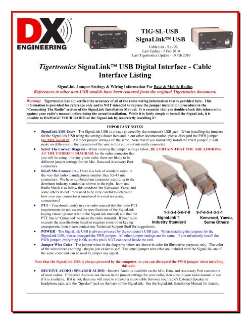
• RJ-45 Mic Connectors - There is a lack of standardization in<br />
the way that radio manufacturers number their RJ-45 mic<br />
connectors. We have numbered our connector according to the<br />
dominant industry standard as shown to the right. Icom and<br />
Radio Shack also follow this standard, but Kenwood, Yaesu and<br />
some others do not. You need to be very careful to determine<br />
how your mic connector is numbered to avoid reversing<br />
connections!<br />
• PTT - You should verify in your radio manual that the radio PTT<br />
requirements do not exceed the specifications of the SignaLink<br />
keying circuit (please refer to the SignaLink manual) and that the<br />
PTT line is “Grounded” to make the radio transmit. If your radio<br />
exceeds the specifications listed or requires some other keying<br />
arrangement, then please contact our Technical Support Staff for suggestions.<br />
• POWER - The SignaLink <strong>USB</strong> is always powered by the computer's <strong>USB</strong> jack. When installing the jumpers for the<br />
SignaLink <strong>USB</strong>, please disregard the PWR jumper. All other jumper settings are the same. If you mistakenly install the<br />
PWR jumper, everything is OK as this pin is NOT connected inside the unit.<br />
• Jumper Wire Color - The jumper wires in the diagrams below are shown in color for illustrative purposes only. The color<br />
of the wires means nothing - they're just easier to see! The actual jumper wires that are included with the SignaLink are all<br />
the same color and can be used to jumper any signal.<br />
Note that the SignaLink <strong>USB</strong> is always powered by the computer, so you can disregard the PWR jumper when installing<br />
this unit.<br />
• RECEIVE AUDIO / SPEAKER AUDIO - Receive Audio is available on the Mic, Data, and Accessory Port connectors<br />
of most radios. If Receive Audio is not shown in the jumper settings for your radio, then consult your radio manual to see<br />
if it is available. If it is not, then you will need to connect a mono cable between your radio's External Speaker or<br />
headphone jack, and the "Speaker" jack on the back of the SignaLink. See the SignaLink Installation Manual for details.
SELECT A MANUFACTURER<br />
NOTE: Please read the "Important Notes" above BEFORE you select your jumper settings. This will save time and may help<br />
prevent you from making a mistake that could possibly damage the SignaLink or your radio. Note that the SignaLink <strong>USB</strong> does<br />
NOT use the PWR jumper wire, so you can disregard this jumper during installation. All other jumper settings are the same.<br />
ADI<br />
8-Pin Round Mic Connector - TIG-SL-CAB8R<br />
Radio Models Pin-out Notes JP-1<br />
AR-146<br />
AR-147<br />
AR-446<br />
Pin 1 - Mic Input<br />
Pin 2 - PTT<br />
Pin 3 - N/C<br />
Pin 4 - N/C<br />
Pin 5 - N/C<br />
Pin 6 - Speaker**<br />
Pin 7 - N/C<br />
Pin 8 - GND<br />
** Speaker audio is available on some models. Check<br />
your radio manual for availability of these signals and<br />
add the appropriate jumpers.<br />
ALINCO<br />
8-Pin Round Mic Connector - TIG-SL-CAB8R<br />
Radio Models Pin-out Notes JP-1<br />
ALD-24T<br />
Pin 1 - Mic Input ** Speaker audio is available on some models. Check<br />
ALR-22T/22HT/72T Pin 2 - PTT your radio manual for availability of these signals and<br />
DR-110T/112T<br />
Pin 3 - N/C add the appropriate jumpers.<br />
DR-130T/135E/135T<br />
DR-150/235T<br />
DR-430T/435E/435T<br />
Pin 4 - N/C<br />
Pin 5 - N/C<br />
Pin 6 - N/C**<br />
DR-510T/570T<br />
Pin 7 - GND<br />
DR-590T/592T/599T Pin 8 - GND<br />
DR-600T/610E/610T<br />
DR-620E/620T<br />
DX-70T/70TH/70EH<br />
DX-77<br />
ALINCO<br />
RJ-45 Mic Connector - TIG-SL-CABRJ4<br />
Radio Models Pin-out Notes JP-1<br />
DR-605E/605T<br />
Pin 1 - N/C Speaker audio is available on some models. Check<br />
Pin 2 - N/C your radio manual for availability of these signals<br />
Pin 3 - N/C and add the appropriate jumpers.<br />
Pin 4 - PTT<br />
Pin 5 - Mic GND<br />
Pin 6 - Mic Input<br />
Pin 7 - GND<br />
Pin 8 - N/C
AZDEN<br />
8-Pin Round Mic Connector - TIG-SL-CAB8R<br />
Radio Models Pin-out Notes JP-1<br />
PCS-5000<br />
PCS-6000<br />
PCS-7000<br />
Pin 1 - Mic Input<br />
Pin 2 - GND<br />
Pin 3 - N/C<br />
Pin 4 - N/C<br />
Pin 5 - N/C<br />
Pin 6 - N/C<br />
Pin 7 - PTT<br />
Pin 8 - N/C<br />
Speaker audio is available on some models. Check your<br />
radio manual for availability of these signals and add the<br />
appropriate jumpers.<br />
DRAKE<br />
4-Pin Round Mic Connector - TIG-SL-CAB4R<br />
Radio Models Pin-out Notes JP-1<br />
TR-7<br />
Pin 1 – Mic Input<br />
TR-22/33<br />
Pin 2 – PTT<br />
UV-3<br />
Pin 3 – N/C<br />
Pin 4 – GND<br />
ELECRAFT 8-Pin Round Mic Connector - TIG-SL-CAB8R<br />
K-2<br />
K-3<br />
Radio Models Pin-out Notes JP-1<br />
Pin 1 - Mic The Mic jack on the K2 can be wired a number of<br />
Pin 2 - PTT different ways, so before installing the jumper wires,<br />
Pin 3 - NC you MUST verify that the pin-out of your K2 matches<br />
Pin 4 - NC that shown here.<br />
Pin 5 - NC<br />
Pin 6 - +5VDC<br />
Pin 7 - GND<br />
Pin 8 - GND<br />
ELECRAFT RJ-45 Mic Connector - TIG-SL-CABK3<br />
Radio Models Pin-out Notes JP-1<br />
K-3 Pin 1 - SPKR<br />
Pin 2 - GND<br />
Pin 3 - MIC<br />
Pin 4 - PTT<br />
Pin 5 - GND<br />
Pin 6 - GND<br />
Pin 7 - N/C<br />
Pin 8 - N/C<br />
Some customers have found that the K3's "Line In" gain<br />
(menu setting) is set to zero by default, thereby resulting<br />
in no power output when transmitting. If up experience<br />
this problem, then please consult your radio manual for<br />
instructions on turning up this control.<br />
Note that the K3 also has a menu setting for the "Line<br />
Out" level, which can be turned up if needed to increase<br />
the RX Audio going into the SignaLink
ICOM<br />
4-Pin Round Mic Connector - TIG-SL-CAB4R<br />
Radio Models Pin-out Notes JP-1<br />
IC-22<br />
IC-202/215/245/280<br />
IC-402/502<br />
IC-551<br />
IC-701<br />
Pin 1 – Mic Input<br />
Pin 2 – PTT<br />
Pin 3 – N/C<br />
Pin 4 – GND<br />
ICOM<br />
IC-1201/1271/1275<br />
IC-22U/25/27/28<br />
IC-228/229/251AE<br />
IC-255/260/271/290<br />
IC-2400/2500<br />
IC-37A/38A/375<br />
IC-3200/3210/3220<br />
IC-45/47/48/471/475/490<br />
IC-505/551/560/575<br />
IC-707/718/720/725/726<br />
IC-728/729/730/735<br />
IC-736/737/738/740/745<br />
IC-746/746PRO<br />
IC-756/756PRO<br />
IC-756PROII/PROIII<br />
IC-7400/7700/7800<br />
IC-751/761/765/775/781<br />
IC-820H/901/910<br />
8-Pin Round Mic Connector - TIG-SL-CAB8R<br />
Radio Models Pin-out Notes JP-1<br />
Pin 1 – Mic Input **Speaker audio (usually Pin #8) is available on some<br />
Pin 2 – N/C** models. Check your radio manual for availability of<br />
Pin 3 – N/C these signals and add the appropriate jumpers.<br />
Pin 4 – N/C<br />
Pin 5 – PTT IMPORTANT: This diagram is for the MIC JACK<br />
Pin 6 – GND only. If the SignaLink is attached to your radio's 8-pin<br />
Pin 7 – GND Accessory Port, then please see the diagram below<br />
Pin 8 – Speaker* under "8-pin DIN Accessory Port Connector".<br />
Check Other <strong>Listing</strong>s for these radios - you may be<br />
able to use the DIN, PACKET, ACCESSORY, or<br />
DATA jack<br />
ICOM<br />
IC-207H**/208H**<br />
IC-281A/281E/281H<br />
IC-703/706/706MKII<br />
IC-2000<br />
IC-2100H**/2200H**<br />
IC-2700**/2720H**<br />
IC-2800**/2820**<br />
IC-7000**<br />
IC-V8000**<br />
ID-800H** /880**<br />
RJ-45 Mic Connector - TIG-SL-CABRJ4<br />
Radio Models Pin-out Notes JP-1<br />
Pin 1 – +8V*** ***Speaker audio is available on some models. Check<br />
Pin 2 – N/C your radio manual for availability of these signals and<br />
Pin 3 – Speaker*** add the appropriate jumpers.<br />
Pin 4 – PTT<br />
Pin 5 – GND (mic) **Speaker Audio is NOT available on the Mic jack of<br />
Pin 6 – Mic Input<br />
this radio.<br />
Pin 7 – GND<br />
Pin 8 – N/C<br />
Check Other <strong>Listing</strong>s for these radios - you may be<br />
able to use the DIN, PACKET, ACCESSORY, or<br />
DATA jack
ICOM<br />
IC-207H/208H<br />
IC-2720H<br />
IC-2800***<br />
IC-2820<br />
IC-703<br />
IC-706MKIIG*<br />
IC-746PRO**<br />
IC-7000**<br />
IC-7400<br />
IC-910H<br />
ID-880<br />
6-Pin Mini DIN Data Port Connector - TIG-SL-CAB6PM<br />
Radio Models Pin-out Notes JP-1<br />
Pin 1 – Data In For special signals requiring un-filtered "discriminator"<br />
Pin 2 – Ground audio, you will need to move the "SPKR" jumper to pin<br />
Pin 3 – PTT #4 (9600 baud output). Note that some newer radios do<br />
Pin 4 – 9600 Out NOT provide this output, so this may not apply to your<br />
Pin 5 – 1200 Out radio.<br />
Pin 6 – Squelch<br />
*IC-706MKIIG - If you are using the Data Port on<br />
this radio, then you must set menu #29 "9600 Mode"<br />
to 1200.<br />
***Mic audio is NOT muted on this radio.<br />
**NOTE: If you are using an ICOM IC-7000, IC-746PRO, or Yaesu FT-450, please note that some customers have reported that these<br />
radios have unusually sensitive Data Ports, which can make adjustment of the SignaLink's TX knob somewhat difficult. If this is the case<br />
with your radio (and the solutions listed above don't work), then you can easily resolve the issue by replacing the SignaLink's "Mic" jumper<br />
wire with a standard 1/4 watt size resistor. Both a 47K and 100K resistor have been reported by several customers to allow easy adjustment<br />
of the power level. Please note that you **DO NOT** solder this resistor. It simply plugs into the JP1 socket in place of the MIC jumper<br />
wire. Be sure that you use a 1/4 watt size resistor, so that you do not damage the SignaLink's socket!<br />
ICOM<br />
IC-275A<br />
IC-707<br />
IC-725/726/728/729<br />
IC-735/736/737<br />
IC-7400<br />
IC-746**<br />
IC-746 PRO**<br />
IC-756 / 756PRO<br />
IC-756 PROII / III<br />
IC-761/765<br />
IC-775/775DSP<br />
IC-781<br />
IC-7600/7700/7800<br />
IC-820H***/821H<br />
IC-910H<br />
IC-M700 PRO<br />
IC-M710<br />
IC-M802<br />
8-Pin DIN Accessory Port Connector - TIG-SL-CAB8PD<br />
Radio Models Pin-out Notes JP-1<br />
Pin 1 - RTTY or N/C<br />
Pin 2 - Ground<br />
Pin 3 - Send<br />
Pin 4 - Mod In<br />
Pin 5 - AF Out<br />
Pin 6 - Squelch<br />
Pin 7 - +13.8V<br />
Pin 8 - ALC<br />
IMPORTANT: This diagram is for the ACCY<br />
PORT only. If the SignaLink is attached to your<br />
radio's 8-pin Round Mic Jack, then please see the<br />
diagram above under "8-Pin Round MIC<br />
Connector".<br />
IC-756PRO users should use digital mode "D-<strong>USB</strong>" or<br />
"D-LSB".<br />
**Some customers have reported that the IC-746 (early<br />
model only) does NOT mute the Mic when keyed from<br />
the Accy Port. If this is the case with your radio, then<br />
you will need to turn the radio's Mic Gain down and/or<br />
unplug the microphone.<br />
**Due to the design of the IC-746PRO, this jack does<br />
NOT support VHF operation. If you want to operate<br />
both HF and VHF, then you'll need to use the 6-pin<br />
mini-DIN Data Port instead.<br />
**IC-746PRO users should use "<strong>USB</strong>/LSB Data" mode<br />
(not regular <strong>USB</strong>/LSB).<br />
***IC-820H users need to set the Modulation Input<br />
Sensitivity switch to "Low", and the Baud Rate<br />
Selection switch to "AMOD".
ICOM<br />
IC-703<br />
IC-706<br />
IC-706MKII<br />
IC-706MKIIG<br />
IC-718<br />
IC-7000**<br />
IC-7200<br />
13-Pin DIN Accessory Port Connector - TIG-SL-CAB13I<br />
Radio Models Pin-out Notes JP-1<br />
<strong>Tigertronics</strong> For VHF operation on the IC-706 and IC-706MKII you<br />
manufactures a will need to move the PTT jumper to Pin #4.<br />
special cable for<br />
ICOM 13-pin For VHF/UHF operation on the IC-706MKIIG and IC-<br />
Accessory Ports. 7000, you should turn the following menu item to OFF:<br />
If you would like Item #30 for IC-706MKIIG<br />
to build your own Item #20 for IC-7000<br />
13-pin cable (not<br />
recommended!), This will force the radio to use the same PTT pin for all<br />
please contact our bands so will not need to change the SignaLink's jumper<br />
Technical Support settings.<br />
Staff for pin-out<br />
and wiring<br />
information.<br />
**This radio does NOT mute the Mic jack when using<br />
the Accy Port, so you will need to turn the Mic Gain<br />
down, or use the 6-pin Mini Din Data Port instead.<br />
ICOM<br />
24 Pin DIN Accessory Port Connector<br />
Radio Models Pin-out Notes JP-1<br />
IC-251AE<br />
IC-730<br />
IC-751<br />
Pin 1 - NC<br />
Pin 2 - +13.8V<br />
Pin 3 - PTT<br />
Pin 4 - AF Out<br />
Pin 5 - Mic Input<br />
Pin 6 - NC<br />
Pin 7 - NC<br />
Pin 8 - GND<br />
Pins 9-24 NC<br />
24-pin DIN Accessory Port Connector - <strong>Tigertronics</strong><br />
does not manufacture a cable for the ICOM 24-pin<br />
Accessory Port connector, but you can easily build one<br />
using our un-terminated radio cable (p/n SLCABNC).<br />
To build your cable, simply wire it straight-through for<br />
pin numbers 1-8 (Pin #1 to Pin #1, Pin #2 to Pin #2,<br />
etc.). Note that your cable MUST wired straightthrough<br />
or the jumper settings shown below will NOT<br />
work, and you might DAMAGE YOUR RADIO OR<br />
THE SIGNALINK!<br />
Pins marked as "NC" are not used by the SignaLink, but<br />
might be connected internally inside the radio.<br />
Japan Radio Company<br />
8-Pin Round Mic Connector - TIG-SL-CAB8R<br />
Radio Models Pin-out Notes JP-1<br />
JST-145<br />
JST-245<br />
Pin 1 - N/C<br />
Pin 2 - N/C<br />
Pin 3 - N/C<br />
Pin 4 - +9V<br />
Pin 5 - GND<br />
Pin 6 - PTT<br />
Pin 7 - Mic GND<br />
Pin 8 - Mic Input
KENWOOD 4-Pin Round Mic Connector - TIG-SL-CAB4R<br />
Radio Models Pin-out Notes JP-1<br />
TS-120S/130S/180S<br />
TS-511S/520/530<br />
TS-600<br />
TS-700<br />
TS-820/830<br />
TR-7200A<br />
TR-7400A<br />
TR-7500<br />
Pin 1 – Mic Input<br />
Pin 2 – PTT<br />
Pin 3 – GND<br />
Pin 4 – Mic GND<br />
Check Other <strong>Listing</strong>s for these radios - you may be<br />
able to use the DIN, PACKET, ACCESSORY, or<br />
DATA jack<br />
KENWOOD 8-Pin Round Mic Connector - TIG-SL-CAB8R<br />
Radio Models Pin-out Notes JP-1<br />
TM-201/211/221/231<br />
TM-241/2530/2550<br />
TM-2570<br />
Pin 1 – Mic Input<br />
Pin 2 – PTT<br />
Pin 3 – N/C<br />
** Speaker audio is available on some models. Check<br />
your radio manual for availability of these signals and<br />
add the appropriate jumpers.<br />
TM-321/331/3530/401 Pin 4 – N/C<br />
TM-421/431/441/521 Pin 5 – 8 VDC** Check Other <strong>Listing</strong>s for these radios - you may be<br />
TM-531/541/621/631 Pin 6 – Speaker**<br />
able to use the DIN, PACKET, ACCESSORY, or<br />
TM-701/721/731<br />
Pin 7 – Mic GND DATA jack<br />
TR-50/751/851<br />
Pin 8 – GND<br />
TS-50/60/140/430/440<br />
TS-450/570/660/670<br />
TS-680/690/701/711<br />
TS-780/790/811/850<br />
TS-870/930/940/950<br />
TS-2000<br />
TW-4000/4100<br />
KENWOOD RJ-45 Mic Connector - TIG-SL-CABRJ4<br />
Radio Models Pin-out Notes JP-1<br />
TM-251/255/261/271<br />
TM-451/455/461<br />
TM-641/642<br />
TM-732/733/741/742<br />
TM-941/942<br />
TM-D700/D700A<br />
TM-D710/710A/E<br />
TM-G707<br />
TM-V7A/V71A<br />
TS-480HX/SAT<br />
Pin 1 – NC<br />
Pin 2 – Speaker**<br />
Pin 3 – Mic<br />
Pin 4 – GND<br />
Pin 5 – PTT<br />
Pin 6 – GND<br />
Pin 7 – +8V**<br />
Pin 8 – NC<br />
**Speaker audio is available on some models. Check<br />
your radio manual for availability of these features and<br />
add the appropriate jumpers.<br />
Check Other <strong>Listing</strong>s for these radios - you may be<br />
able to use the DIN, PACKET, ACCESSORY, or<br />
DATA jack
KENWOOD 6-Pin Mini DIN Port Connector - TIG-SL-CAB6PM<br />
Radio Models Pin-out Notes JP-1<br />
Pin 1 – Data In For special signals requiring un-filtered "discriminator"<br />
Pin 2 – Ground audio, you will need to move the "SPKR" jumper to pin<br />
Pin 3 – PTT #4 (9600 baud output). Note that some newer radios do<br />
Pin 4 – 9600 Out NOT provide this output, so this may not apply to your<br />
Pin 5 – 1200 Out radio.<br />
Pin 6 – Squelch<br />
TM-251<br />
TM-271**/271A**<br />
TM-451<br />
TM-D700/D700A<br />
TM-D710/710A/E<br />
TM-G707<br />
TM-733A<br />
TM-V7/V7A/V71A<br />
TS-480HX/SAT<br />
**Only European models of the TM-271 and TM-271A<br />
have the 6-pin mini-DIN Data Port. All other models<br />
will need to use the RJ-45 Mic cable.<br />
Check Other <strong>Listing</strong>s for these radios - you may be<br />
able to use the DIN, PACKET, ACCESSORY, or<br />
DATA jack<br />
KENWOOD<br />
13-Pin DIN Accessory Port Connector - TIG-SL-CAB13K<br />
Our 13-pin cable works with ALL Kenwood radio's that have a 13-pin Accessory Port, however there are two possible jumper settings. If<br />
your radio is not listed in Figure 1 or Figure 2, then you will need to try both jumper settings to determine which PTT configuration your<br />
radio requires. We suggest that you try the settings in Figure 1 first. Your radio will NOT be damaged if you install the PTT jumper<br />
using the wrong configuration - you just won’t be able to transmit! After you have installed the jumpers, be sure to set the sound card<br />
audio levels as outlined in the SignaLink manual. If you do not set the levels correctly, then the SignaLink may not transmit, and you might<br />
mistake the problem for incorrect jumper settings.<br />
Figure 1 Figure 2 Notes<br />
TS-2000 users should set Menu 50F to 1200<br />
Baud. Menu 50B can be used to increase the<br />
radio's power output if it is too low. We suggest<br />
that you change these menu items even if they<br />
already appear to be set correctly. Set 50B to<br />
zero, and then to five. Set 50F to 9600, and then<br />
to 1200. To increase the Receive Audio Level<br />
on the TS-2000, you can adjust menu 50C.<br />
This configuration is the most common<br />
and works with early Kenwood radios such<br />
as the TS-140, TS-450S, TS-870 and TS-<br />
950. Some newer radios such as the TS-<br />
570D and TS-2000/X also use these<br />
settings.<br />
This configuration is less common and is<br />
used by some newer radios (TS-690 for<br />
example) and some older radios such as<br />
the TS-440. These settings are identical<br />
to those in Figure 1, except for the PTT<br />
jumper, which has been replaced by a<br />
diode module (supplied with cable).<br />
TS-570 users should set Menu #33 to 1 or 2 (a<br />
setting of zero will result in no transmit power).<br />
Menu #34 should be set at 4-5 and can be<br />
increased to provide more Receive Audio if<br />
needed.<br />
TS-940 users need to use the jumper settings<br />
shown in figure 1, except for the PTT jumper.<br />
The PTT jumper should be connected to pin #4<br />
instead of pin #3.<br />
TS-440 users please note that your radio's Mic<br />
Gain control will affect your power output. We<br />
suggest setting this control to 50% and then<br />
adjust it as needed so that the SignaLink's TX<br />
knob can be used to adjust the power output<br />
properly.
MIDLAND<br />
4-Pin Round Mic Connector - TIG-SL-CAB4R<br />
Radio Models Pin-out Notes JP-1<br />
13-510 Pin 1 – Mic Input<br />
Pin 2 – GND<br />
Pin 3 – N/C<br />
Pin 4 – PTT<br />
RADIO SHACK RJ-45 Mic Connector - TIG-SL-CABRJ4<br />
HTX-212<br />
HTX-242<br />
Radio Models Pin-out Notes JP-1<br />
Pin 1 – N/C<br />
Speaker audio is available on some<br />
Pin 2 – GND models. Check your radio manual for<br />
Pin 3 – N/C<br />
availability of these signals and add the<br />
Pin 4 – N/C<br />
appropriate jumpers.<br />
Pin 5 – Mic Input<br />
Pin 6 – PTT<br />
Pin 7 – N/C<br />
Pin 8 – N/C<br />
SGC<br />
8-Pin Round Mic Connector - TIG-SL-CAB8R<br />
Radio Models Pin-out Notes JP-1<br />
SGC-2020<br />
Pin 1 – Mic<br />
Pin 2 – PTT<br />
Pin 3 – NC<br />
Pin 4 – NC<br />
Pin 5 – NC<br />
Pin 6 – RX Audio<br />
Pin 7 – Mic GND<br />
Pin 8 – GNC
TEN-TEC<br />
4-Pin Round Mic Connector - TIG-SL-CAB4R<br />
Radio Models Pin-out Notes JP-1<br />
Pegasus<br />
Pin 1 – Mic Input<br />
Pin 2 – GND<br />
Pin 3 – PTT<br />
Pin 4 – N/C<br />
These jumper settings work with most Ten-Tec Mic<br />
jacks (not just the Pegasus). However you should verify<br />
that your radio has the same pin-out before installing<br />
them.<br />
Check Other <strong>Listing</strong>s for these radios - you may be able<br />
to use the DIN, PACKET, ACCESSORY, or DATA<br />
jack<br />
TEN-TEC<br />
5-Pin DIN Accessory Connector - TIG-SL-CAB5PD<br />
Radio Models Pin-out Notes JP-1<br />
Argonaut V<br />
Jupiter<br />
Omni VII<br />
Pegasus<br />
Pin 1 - Mic Input<br />
Pin 2 - GND<br />
Pin 3 - PTT<br />
Pin 4 - AF Output<br />
Pin 5 - NC<br />
The Ten-Tec Jupiter must be in "Line" to use the ACCY<br />
jack (set in radio menu).<br />
TEN-TEC<br />
Orion<br />
Orion II<br />
TEN-TEC Delta II Users: Our 8-pin<br />
DIN cable is NOT compatible with<br />
the TEN-TEC Delta II. You must<br />
connect the SignaLink to this radio's<br />
4-pin Mic jack.<br />
8-Pin DIN Accessory Connector - TIG-SL-CAB8PD<br />
Radio Models Pin-out Notes JP-1<br />
Pin 1 - Aux In **On the original Orion, the "Audio"<br />
Pin 2 - GND menu determines what audio is available<br />
Pin 3 - PTT<br />
on pins 4 and 6, so the SPKR jumper will<br />
Pin 4 - Line Out** need to be set accordingly.<br />
Pin 5 - NC<br />
Pin 6 - Line Out** **On the Orion II, Pin #4 is ALWAYS<br />
Pin 7 - FSK<br />
the audio output.<br />
Pin 8 - NC
YAESU<br />
4-Pin Round Mic Connector - TIG-SL-CAB4R<br />
Radio Models Pin-out Notes JP-1<br />
FT-101<br />
FT-101ZD<br />
Pin 1 – GND<br />
Pin 2 – Mic Input<br />
Pin 3 – PTT<br />
Pin 4 – N/C<br />
YAESU<br />
FT-107/107M<br />
FT-736/736R<br />
FT-747/757<br />
FT-757GX/767GX<br />
FT-840<br />
FT-847**<br />
FT-890**<br />
FT-920**<br />
FT-950**<br />
FT-990**<br />
FT-1000**/1000D**<br />
FT-1000MP**<br />
FT-2200<br />
FT-5100<br />
8-Pin Round Mic Connector - TIG-SL-CAB8R<br />
Radio Models Pin-out Notes JP-1<br />
Pin 1 – N/C **On the FT-890, FT-990, and the FT-1000 and 1000D,<br />
Pin 2 – N/C you should also jumper Pin #2 and Pin #5 to Ground.<br />
Pin 3 – N/C<br />
Pin 4 – N/C **On the FT-847, FT-920, FT-950 and FT-1000MP,<br />
Pin 5 – N/C you should also jumper Pin #5 to Ground.<br />
Pin 6 – PTT<br />
Pin 7 – GND<br />
Pin 8 – Mic Input<br />
Speaker audio is available on some models. Check your<br />
radio manual for availability of these signals and add the<br />
appropriate jumpers.<br />
Check Other <strong>Listing</strong>s for these radios - you may be<br />
able to use the DIN, PACKET, ACCESSORY, or<br />
DATA jack<br />
YAESU<br />
FT-100**<br />
FT-1500M<br />
FT-1802<br />
FT-2800M<br />
FT-2900R<br />
FT-7800R<br />
RJ-11 Mic Connector - TIG-SL-CABRJ1<br />
Radio Models Pin-out Notes JP-1<br />
Pin 1 – N/C **With the FT-100, the PTT jumper MUST be replaced<br />
Pin 2 – N/C with a standard 1/4 watt 27k resistor.<br />
Pin 3 – +9V<br />
Pin 4 – GND Other Yaesu models with an RJ-11 Mic jack might also<br />
Pin 5 – Mic Input use these same settings (check your radio manual).<br />
Pin 6 – SW1<br />
Pin 7 – N/C<br />
Pin 8 – N/C<br />
Check Other <strong>Listing</strong>s for these radios - you may be<br />
able to use the DIN, PACKET, ACCESSORY, or<br />
DATA jack
YAESU<br />
RJ-45 Mic Connector - TIG-SL-CABRJ4<br />
Radio Models Pin-out Notes JP-1<br />
FT-2400<br />
FT-2500<br />
Pin 1 – N/C<br />
Pin 2 – Speaker<br />
Pin 3 – PTT<br />
Speaker audio is available on some models. Check your<br />
radio manual for availability of these signals and add the<br />
appropriate jumpers.<br />
Pin 4 – Mic Input<br />
Pin 5 – GND<br />
Check Other <strong>Listing</strong>s for these radios - you may be<br />
Pin 6 – N/C<br />
able to use the DIN, PACKET, ACCESSORY, or<br />
Pin 7 – N/C<br />
DATA jack<br />
Pin 8 – N/C<br />
YAESU<br />
RJ-45 Mic Connector - TIG-SL-CABRJ4<br />
Radio Models Pin-out Notes JP-1<br />
FT-450<br />
Pin 1 – N/C Receive Audio is not available on this connector.<br />
FT-817<br />
Pin 2 – N/C<br />
FT-897<br />
Pin 3 – N/C<br />
Check Other <strong>Listing</strong>s for these radios - you may be<br />
FT-900<br />
Pin 4 – Mic GND<br />
able to use the DIN, PACKET, ACCESSORY, or<br />
Pin 5 – Mic<br />
DATA jack<br />
Pin 6 – PTT<br />
Pin 7 – GND<br />
Pin 8 – N/C<br />
YAESU<br />
FT-100/100D<br />
FT-450***<br />
FT-817/817ND<br />
FT-847**<br />
FT-857/897<br />
FT-950<br />
FT-1500M<br />
FT-7100/7800R<br />
FT-8100/8800R<br />
FT-8900R<br />
6-Pin Mini DIN Data Port Connector - TIG-SL-CAB6PM<br />
Radio Models Pin-out Notes JP-1<br />
Pin 1 – Data In For special signals requiring un-filtered<br />
Pin 2 – Ground "discriminator" audio, you will need to move the<br />
Pin 3 – PTT "SPKR" jumper to pin #4 (9600 baud output). Note<br />
Pin 4 – 9600 Out that some newer radios do NOT provide this output, so<br />
Pin 5 – 1200 Out this may not apply to your radio.<br />
Pin 6 – Squelch<br />
**On the FT-847 the Data Port supports VHF & UHF<br />
Packet only.<br />
***NOTE: If you are using an ICOM IC-7000, IC-746PRO, or Yaesu FT-450, please note that some customers have reported that these<br />
radios have unusually sensitive Data Ports, which can make adjustment of the SignaLink's TX knob somewhat difficult. If this is the case<br />
with your radio (and the solutions listed above don't work), then you can easily resolve the issue by replacing the SignaLink's "Mic" jumper<br />
wire with a standard 1/4 watt size resistor. Both a 47K and 100K resistor have been reported by several customers to allow easy adjustment<br />
of the power level. Please note that you **DO NOT** solder this resistor. It simply plugs into the JP1 socket in place of the MIC jumper<br />
wire. Be sure that you use a 1/4 watt size resistor, so that you do not damage the SignaLink's socket!
YAESU<br />
5-Pin DIN Packet Connector - TIG-SL-CAB5PD<br />
Radio Models Pin-out Notes JP-1<br />
FT-920*<br />
FT-1000D/MP***<br />
FT-1000MPMKV**<br />
FT-1000MPMKV-Field**<br />
FT-2000<br />
FTDX-9000/D/MP<br />
Pin 1 – Data In<br />
Pin 2 – GND<br />
Pin 3 – PTT<br />
Pin 4 – Data Out<br />
Pin 5 – NC<br />
*On the FT-920, the AFSK/FSK switch MUST be set<br />
to AFSK, and you must be in "Data" mode (push the<br />
front panel "Data" button). The Mic Gain control<br />
appears to affect the operation of the Packet jack, so<br />
we suggest setting this to 50% and then adjusting as<br />
needed..<br />
**The FT-1000MPMKV and FT-1000MKV Field<br />
MUST be in "Packet" mode (NOT usb!) for digital<br />
operation. For PSK31 or other "<strong>USB</strong>" digital modes,<br />
you'll need to set your radio's "User Mode" (selection<br />
8-6) to "PS31U". This will configure the radio to look<br />
at the Packet jack and use the correct side band for<br />
PSK31. For more detailed information on this<br />
(including settings for other modes), see "<strong>Digital</strong><br />
Modem Operation" in your radio manual.<br />
***This jack supports only FM and LSB, which is not<br />
compatible with the majority of digital modes.<br />
YAESU FT-847 ONLY 3.5 mm Stereo "Data I/O" Jack - TIG-SL-CABNC<br />
Notes<br />
For the FT-847, we recommend that you attach the SignaLink<br />
to the "Data I/O" jack. This jack works for all modes and will<br />
let you keep your microphone plugged into the radio. We do<br />
not stock a cable for this jack however, so you will need to<br />
build your own using one of our un-terminated radio cables.<br />
The picture shows how to wire this cable and install the jumper<br />
wires.<br />
Notes:<br />
1. R1 = 2.7k 1/4 watt resistor, C1 = 0.1uf non-polarized<br />
capacitor<br />
2. To prevent damage to socket JP1, the diameter of R1 and<br />
C1's leads should be no larger than those of the supplied<br />
jumper wires (24 gage).<br />
3. The wire colors shown are for our un-terminated ("NC"<br />
cable. Other cables may not be wired the same.<br />
JP-1
SignaLink <strong>USB</strong> Troubleshooting,Technical FAQ, and Operating Tips<br />
Common Problems<br />
These are the most common problems reported to our Technical Support Staff. If you are unable to resolve your problem, or if you<br />
do not find your problem listed here, then please contact <strong>Tigertronics</strong> Technical Support Staff for assistance.<br />
1. My SignaLink <strong>USB</strong> was working perfectly but now will no longer Transmit (PTT LED is OFF).<br />
2. Radio won't transmit (SignaLink <strong>USB</strong>'s PTT indicator is OFF).<br />
3. Radio won't transmit (SignaLink <strong>USB</strong>'s PTT indicator is ON).<br />
4. Radio transmits, but there is no power output or it is too low.<br />
5. My transmit signal is wide and distorted.<br />
6. The SignaLink <strong>USB</strong>'s TX control is "touchy", making if difficult to control my RF power.<br />
7. I can't seem to receive.<br />
8. Why can't I receive some stations.<br />
9. Other stations never come back to me when I answer their CQ, or they tell me that I'm off frequency<br />
10. Soundcard Calibration / Sample Rate offset error<br />
11. Windows System Sounds cause the SignaLink <strong>USB</strong> to transmit.<br />
Technical Questions / Operating Tips<br />
1. How do I operate "direct keyed" CW with the SignaLink?<br />
2. Do I select a serial port when configuring my communications program?<br />
3. What general settings must I make when configuring my communications program?<br />
4. I see "<strong>USB</strong> Audio Device", but not "<strong>USB</strong> Audio Codec" when using the SignaLink <strong>USB</strong> - Is this correct?<br />
Windows Issues<br />
1. Windows 98 can't find a file during installation.<br />
2. Windows resets the SignaLink <strong>USB</strong>'s software volume controls to incorrect positions<br />
3. 11025 Hz Sample Rate offset error on some Windows ME, 2000 and XP systems<br />
My SignaLink <strong>USB</strong> was working perfectly but now will no longer Transmit - This is the most common problem we hear about<br />
and it is virtually **always** due to the software volume controls being reset by Windows. This can happen if you unplug the <strong>USB</strong><br />
cable, or change the default sound card in Windows. Please check your volume controls carefully. Note that they will most likely be<br />
reset exactly opposite of how they should be set, so they can look correct at a glance. As outlined in the SignaLink Installation<br />
Manual, the "Speaker" control should be at 100% (max) and the "Wave" control should be at 50%. Be sure that your volume control<br />
panel shows "<strong>USB</strong> Audio Codec" in the lower left hand corner, or you will be adjusting the volume for the wrong card!<br />
Radio won't transmit (SignaLink <strong>USB</strong>'s PTT indicator is OFF) -<br />
• Verify that the SignaLink <strong>USB</strong>’s PWR LED is ON. If it is not, then make sure that the SignaLink <strong>USB</strong>'s PWR switch is<br />
pressed in and the <strong>USB</strong> cable is securely connected to the computer and the SignaLink.<br />
• Verify that your communications program is configured to use the SignaLink <strong>USB</strong>’s built-in sound card. The program<br />
should have “<strong>USB</strong> Audio CODEC” (or "<strong>USB</strong> Audio Device" with Windows Me/2000) selected as the sound card for both<br />
Transmit and Receive.<br />
• Verify that the PLAYBACK volume controls for the SignaLink <strong>USB</strong> are set according to the “Setting The Audio Levels”<br />
procedure. If they are too low, then the SignaLink <strong>USB</strong>'s PTT LED will NOT turn ON. Incorrect software volume control<br />
settings are the number one cause of transmit problems, so please be sure to see the "My SignaLink <strong>USB</strong> was working<br />
perfectly but now will no longer Transmit" issue above.<br />
• If the SignaLink is plugged into a <strong>USB</strong> hub, please remove it from the hub and plug it directly into the computer's <strong>USB</strong><br />
jack until the problem is resolved. Un-powered hubs and some powered hubs cannot supply enough power for the<br />
SignaLink to operate properly, so (Receive will usually work, but Transmit may not). See our SignaLink FAQ for more<br />
details on this.<br />
Radio won't transmit (SignaLink <strong>USB</strong>'s PTT indicator is ON) - If the SignaLink <strong>USB</strong>'s PTT LED turns ON but the radio doesn't<br />
switch to transmit, then you have most likely installed the PTT jumper incorrectly on JP-1 (go back and double-check ALL<br />
jumpers!). If the SignaLink is attached to your radio’s Data or Accessory Port, then another possible cause is that your radio isn’t<br />
configured properly to use that port. Some radios require the radio to be set to a "digital" mode such as "Packet", "User-u", "<strong>Digital</strong>-<br />
<strong>USB</strong>", etc. Consult your radio manual and verify that your radio is in the correct mode.
NOTE: If the SignaLink is plugged into a <strong>USB</strong> hub, then you need to verify that the hub is a powered hub. Non-powered hubs may<br />
not supply enough power for the SignaLink to operate properly (Receive will work, but Transmit may not). See our SignaLink FAQ<br />
for more details on this.<br />
Radio transmits but there is no power output, or it is too low – The SignaLink <strong>USB</strong> can provide more than enough Transmit<br />
Audio to drive any radio to full power. If you have followed the “Setting The Audio Levels” procedure in the SignaLink <strong>USB</strong> manual<br />
and still cannot get enough power, then check the following:<br />
• If you are using a CAT interface, then you need to disable "PTT by CAT Control" (or similarly worded option), so that the<br />
SignaLink can key the radio (not the CAT interface!). This is necessary because some radio's will only look for Transmit<br />
Audio on the Mic jack if the radio is switched into Transmit by the CAT interface. Note that this is a design issue with the<br />
**radio** and has absolutely nothing to do with the SignaLink.<br />
• Verify that your radio’s “Forward Power” (sometimes called “RF Power” or “Carrier Power”) control is set to maximum.<br />
On newer radios with menu settings, this is normally a menu item (not a knob). Note that you do NOT want to run full<br />
power as measured on your radio, or external watt/power meter. You should set this control to max and then adjust the<br />
power to the desired level using the SignaLink <strong>USB</strong>'s TX control. This is normally no more than 25-35 watts for PSK31<br />
and 50 watts for most other 100% duty cycle modes, but you should check your radio manual to insure that these power<br />
levels are OK for your radio. Continued transmissions at power levels higher than those recommended by your radio<br />
manufacturer can damage your radio, so please check your radio manual.<br />
• If the SignaLink is attached to your radio’s Mic jack, then try turning up your radio’s Mic Gain control.<br />
• Confirm that your transmit modulation in your communication program is set within the range of 500hz to 2500hz. In<br />
PSK31 programs this means that you should be within the range of 500 to 2500 Hz in the waterfall display. If you go<br />
outside of these limits then your radio will not be able to pass the modulation and your power will drop significantly.<br />
• Adjust the Windows “Wave” PLAYBACK volume control higher.<br />
• See the “Special Jumpers” section of this manual and install JP3. This will dramatically increase the SignaLink’s Transmit<br />
Audio level. Note that this is NOT needed for most radios, so you really need to be sure that everything else is correct<br />
before doing this.<br />
• If the SignaLink is attached to a Kenwood 13-pin Accessory Port, then you may have set the PTT jumper incorrectly.<br />
Double-check the document that was supplied with your radio cable to see if your radio requires a standard PTT jumper or<br />
the diode module to be installed.<br />
My transmit signal is wide or distorted - This is generally the result of over-driving your radio. Verify that your radio’s speech<br />
processor/compressor is turned OFF. Your radio’s “Forward Power” control (sometimes called “RF Power” or “Carrier Power”)<br />
should be set to maximum. If you have lowered this control to decrease your transmit power, then you more than likely have not set<br />
the audio levels correctly, and are overdriving your radio. Follow the “Setting The Audio Levels” procedure to correct this problem.<br />
If the above mentioned radio controls are set correctly, then try turning the radio’s Mic, Data or Accy Port gain and see if that<br />
improves the quality of your signal (Data/Accy Port gain is usually a radio menu setting). If this has no effect, then you may have the<br />
software PlayBack volume controls, or the SignaLink <strong>USB</strong>’s TX level control set to high. See the “Setting The Audio Levels”<br />
procedure to correct this. Contact Tech Support if you cannot resolve this problem.<br />
The SignaLink <strong>USB</strong>'s TX control is "touchy", making it difficult to control my RF power - This is most likely because the<br />
radio’s Mic, Data or Accy Port gain control is set too high, but before continuing, please be sure that you have NOT installed special<br />
jumper JP3 inside the SignaLink. This jumper is rarely needed, and will normally cause the SignaLink to provide too much audio to<br />
the radio, making adjustment of the TX knob difficult.<br />
If the SignaLink is attached to the radio's Mic jack, then you can resolve this issue by turning the radio’s Mic Gain control down. If<br />
the SignaLink is attached to the radio's Data or Accy Port, then your radio likely has a menu setting or trimmer to adjust the gain.<br />
This gain adjustment is often called “Packet Input Level” or “Packet Gain”, but may have another name, so check your radio manual<br />
carefully. Note that the radio's Mic Gain control on some older radios may also affect the Data/Accy Port, so you should check this<br />
as well.<br />
If the above solutions don't help, then you can try lowering the Windows software "Wave" control for "<strong>USB</strong> Audio Codec". We<br />
normally suggest setting his control to 50%, but it can be lowered to just above the point where the SignaLink's PTT circuit stops<br />
working (PTT LED turns OFF). We recommend finding this threshold while transmitting a steady test tone, and then setting the<br />
Wave control just slightly higher than the threshold point to provide reliable PTT operation. Note that the SignaLink's Delay knob<br />
should be set to minimum when making this adjustment.<br />
NOTE: If you are using an ICOM IC-7000, IC-746PRO, or Yaesu FT-450, please note that some customers have reported that these<br />
radios have unusually sensitive Data Ports, which can make adjustment of the SignaLink's TX knob somewhat difficult. If this is the<br />
case with your radio (and the solutions listed above don't work), then you can easily resolve the issue by replacing the SignaLink's
"Mic" jumper wire with a standard 1/4 watt size resistor. Both a 47K and 100K resistor have been reported by several customers to<br />
allow easy adjustment of the power level. Please note that you **DO NOT** solder this resistor. It simply plugs into the JP1 socket<br />
in place of the MIC jumper wire. Be sure that you use a 1/4 watt size resistor, so that you do not damage the SignaLink's socket!<br />
I can't seem to receive - There are several possible causes for this problem:<br />
• SignaLink <strong>USB</strong>’s RX level control or radio level control set too low – Verify that the SignaLinks RX level control is turned<br />
up (clockwise). If you are using Speaker Audio from the radio (not a fixed level signal from a Data/Accy Port), then verify<br />
that your radio volume is turned up. If your communications program doesn’t show any signs of Receive Audio (no<br />
waterfall display, etc.), then please review the “Connecting The Radio” and "Setting The Audio Levels" sections of the<br />
SignaLink <strong>USB</strong> Installation Manual.<br />
• Computer too slow or incompatible with software. Software not configured properly - Check the documentation for the<br />
program that you are using and verify that your computer meets the minimum requirements. Verify that the program is<br />
configured correctly (the SignaLink <strong>USB</strong>’s “<strong>USB</strong> Audio CODEC” should be selected as the sound card). If all else fails,<br />
try using a different program.<br />
Why Can't I Receive Some Stations - No matter how good your antenna and radio are, there will always be some stations that you<br />
cannot copy (even with strong signals!). While the reason for this may be because of operator error (wrong mode or baud rate, off<br />
frequency, etc.), radio wave propagation problems can often prevent you from receiving. Some modes are more susceptible to this<br />
than others. For example, even though PSK31 usually works very well with weak signals, sometimes even strong PSK31 signals<br />
cannot be copied at all because of multipath and Doppler Shift propagation problems. Other modes like HF Packet and RTTY do not<br />
work well with weak signals and are susceptible to multipath and Doppler Shift.<br />
Windows "System Sounds" Cause The SignaLink <strong>USB</strong> To Transmit – This will NOT happen if you configure Windows to use<br />
your computer’s sound card as the default sound card. See the “Connecting The Computer” section of the SignaLink <strong>USB</strong> Installation<br />
Manual to resolve this problem.<br />
How do I operate "direct keyed" CW with the SignaLink - This is done by simply connecting the SignaLink's PTT and Ground<br />
lines to the "Key" and "Ground" lines of your radio's Key jack. One of our un-terminated radio cables can be used to make these<br />
connections. You will need to attach the appropriate plug for your radio's Key jack to this cable. Using our SLCABNC cable, we<br />
suggest attaching the white/orange wire to the tip of the plug, and the orange wire to the plug's body/sleeve. You will then need to<br />
install the SignaLink jumpers as follows; PTT to 1, and G (ground) to 2. Note that direct keyed CW is limited to about 25 WPM on<br />
Transmit (there is no limit on Receive), so if you need to transmit faster than this, you'll want to run AFSK CW.<br />
Do I select a serial port when configuring my communications program - Some communications programs will have a COM Port<br />
selection for PTT (Push To Talk), and some will also have COM Port selection for radio control ("CAT" control). The SignaLink<br />
does NOT use a serial port for PTT control, so your communications program should be set to "None", "COM0", "External VOX", or<br />
a similar setting to indicate that a serial port is not used. Some newer programs have a "SignaLink" setting that should be used if<br />
available.<br />
If you have a CAT interface and will be using it for radio control, then the CAT control portion of your communications program<br />
should be set to use the COM Port that the CAT interface is plugged into. If you do not have a CAT interface, then this should also<br />
be set to "None" (or similar).<br />
What general settings must I make when configuring my communications program - As explained in the SignaLink Installation<br />
Manual, you must configure your communications program to use "<strong>USB</strong> Audio Codec" as the sound card for BOTH Transmit and<br />
Receive. You may also need to disable serial port PTT control and CAT control as mentioned in the question above. These are<br />
typically the only settings required to use the SignaLink <strong>USB</strong> with most programs, but some programs do have other "special"<br />
program specific settings such as "use AFSK in place of FSK", or "send CW as AFSK" that may need to be set. In general, you can<br />
configure most programs properly if you remember that you will be operating AFSK (audio tones/modulation) and NOT using a<br />
serial port for.<br />
I see "<strong>USB</strong> Audio Device", but not "<strong>USB</strong> Audio Codec" when using the SignaLink <strong>USB</strong> - Is this correct? Windows ME and<br />
2000 may display the SignaLink <strong>USB</strong> as "<strong>USB</strong> Audio Device" instead of "<strong>USB</strong> Audio Codec". If this is the case on your system,<br />
then you simply need to select "<strong>USB</strong> Audio Device" instead of "<strong>USB</strong> Audio Codec" as the sound card.
Windows 98 can't find a file during installation - There is a bug in all versions of Windows 98 that causes the Operating System to<br />
sometimes "forget" what drive the installation CD is in during installation. If you receive a "Can't Find File..." error message during<br />
installation of the SignaLink <strong>USB</strong>, then you will need to manually enter the location of your Windows CD drive into the dialog box<br />
when prompted. For example, if your CD drive is "D:" then you will type "D:\WIN98". Note that you may also be able to click the<br />
location drop down menu and select the correct CD drive location.<br />
Windows resets the SignaLink <strong>USB</strong>'s software volume controls to incorrect positions - If the SignaLink's <strong>USB</strong> cable is<br />
unplugged or the default sound card in the computer is changed, Windows may reset the SignaLink's software volume controls to<br />
incorrect levels. The symptom for this problem is that the SignaLink <strong>USB</strong> was working perfectly, but now will not transmit. This<br />
issue can be resolved by manually setting the "Speaker" volume control back to maximum, and the "Wave" control to 50%, or by<br />
using the "QuickMix" utility to save and restore your volume control settings.<br />
11025 Hz Sample Rate offset error - Due to a Windows system issue, some Windows ME, 2000 and XP computers may show an<br />
abnormal sample rate offset error of around 7000 ppm at the 11025 Hz sample rate (other sample rates are NOT affected). If this<br />
offset error occurs on your computer, it can result in your transmit (modulation) frequency being off from your receive frequency.<br />
When operating digital modes, this can manifest itself in several different ways. With PSK31, other stations may not respond when<br />
you answer their CQ, or they may respond but say that you are off frequency. It can also result in both you and the person that you're<br />
talking to "walking" across the waterfall as each of you corrects your tuning after each transmission. On MT63, this problem can<br />
result in other stations not being able to copy you, or they receive your text in lower or upper case only, or certain characters such as<br />
spaces are missing.<br />
This issue can be easily resolved in virtually all cases by simply changing the sample rate in your communication program from<br />
11025 Hz to 12000 Hz. It's important to note that changing the sample rate will NOT hurt anything if this problem doesn't exist on<br />
your computer, so if you're not sure, we suggest changing it just to avoid the issue. Also, other standard sample rates (8000, 22050,<br />
44.1, etc.) work just fine and do not need to be changed. It should also be noted that Windows 98SE and Windows Vista systems<br />
never show this offset error.<br />
Sound Card Calibration - Transmit and Receive sample rate errors and sample rate offset errors occur with all sound cards, and can<br />
cause you to experience transmit and/or receive problems when operating digital, if the error is large enough. The sample rate error<br />
can cause a variety of problems depending on the mode that you are using. With PSK31, other stations may not respond when you<br />
answer their CQ, or they may respond but say that you are off frequency. Other stations may respond to your CQ, but be off<br />
frequency so that you can't copy them. These errors can also result in both you and the person that you're talking to "walking" across<br />
the waterfall as each of you corrects your tuning after each transmission. On MT63, this problem can result in other stations not<br />
being able to copy you at all, or they receive your text in lower or upper case only, or certain characters such as spaces are missing.<br />
With SSTV, sample rate errors result in slanted pictures.<br />
If you are using Window ME, 2000, or XP it is important that you see the "11025 Hz Sample Rate offset error" issue above before<br />
going any further. This will resolve most sound card calibration issues. If this doesn't completely fix the problem you are<br />
experiencing, then sound card calibration might be necessary to remove the remaining error. This can be done with your<br />
communication program's built-in calibration routine if available (see your program's documentation), or with the "Check Sample<br />
Rate" utility that comes free with the popular "Mix-W" program. If you use the Check Sample Rate utility, be sure to select the<br />
SignaLink's sound card and let it run for at least 30 minutes. Do not use your computer for anything else during this time, and do not<br />
let it go into sleep or suspend mode, or the results will be invalid. After at least 30 minutes of operation, the TX/RX offset error<br />
displayed at the bottom of the program window will settle and can entered your communication program to correct for any sample<br />
rate error. In DigiPan, for example, you would enter these numbers in the "Configure - Sample Rate Corrections" menu. Other<br />
programs have similar options - See your program's Help documentation for details.<br />
For the most accurate calibration possible, you can calibrate your system using the sound card calibration procedure contained in the<br />
MMSSTV program's "Help" documentation. This procedure uses your transceiver and the WWV time station to obtain sub 1Hz<br />
accuracy. While some users might want to do this for the sake of having the most accurate signal possible, it should be noted that<br />
this isn't normally necessary. Excellent performance can virtually always be achieved by using one of the procedures listed above.
SignaLink "Plug & Play"<br />
Jumper Modules<br />
Our new "Plug & Play" jumper modules plug into the SignaLink in place of the jumper wires that you would<br />
normally use. This greatly simplifies installation and completely eliminates the possibility of installing the<br />
jumper wires incorrectly. Swapping radios is also easier, as you just unplug one module and plug in another.<br />
Most jumper modules are compatible with both the SignaLink <strong>USB</strong> and older SignaLink SL-1+. Modules are<br />
currently available for the most popular radio configurations, and new modules for other configurations will be<br />
added soon.<br />
Which jumper module do I need for my radio?<br />
SLMOD6PM<br />
This jumper module is compatible with all ICOM, Kenwood and Yaesu radios that have<br />
a 6-pin mini-DIN Data Port.<br />
SLMOD8PD<br />
This jumper module is compatible with all ICOM radios that have an 8-pin DIN Accy<br />
Port. Note that this module is for ICOM radios only. It cannot be used with other radio<br />
brands even if they use the same type of Accy Port connector (Ten-Tec, etc.).<br />
SLMOD13I<br />
This jumper module is compatible with all ICOM radios that have a 13-pin Accy Port.<br />
SLMOD13K<br />
This jumper module is compatible with all KENWOOD radios that have a 13-pin Accy<br />
Port. NOTE: This module will work with the SignaLink <strong>USB</strong> only. It is physically<br />
too tall to fit inside the older SL-1+ model.<br />
===========================================<br />
SLMOD6PM - This jumper module is compatible with all<br />
ICOM, Kenwood, and Yaesu radios that have a 6-pin mini-<br />
DIN Data Port. This includes but is not limited to the radios<br />
listed below. Be sure to see our radio wiring and jumper<br />
settings page for any special notes on your radio (menu<br />
settings, etc.).<br />
ICOM<br />
IC-207H, IC-208H<br />
IC-2720H<br />
IC-2800, IC-2820<br />
IC-703<br />
IC-706MKIIG<br />
IC-746PRO<br />
IC-7000<br />
IC-7400<br />
IC-910H<br />
KENWOOD<br />
TM-251<br />
TM-271**, TM-271A**<br />
TM-451<br />
TM-D700, TM-D700A<br />
TM-D710, TM-D710A, TM-D710E<br />
TM-G707<br />
TM-733A<br />
TM-V7, TM-V7A, TM-V71A<br />
TS-480HX, TS-480SAT<br />
**European TM-271/271A models only<br />
YAESU<br />
FT-100, FT-100D<br />
FT-817, FT-817ND<br />
FT-450<br />
FT-847**<br />
FT-857<br />
FT-897<br />
FT-950<br />
FT-1500M<br />
FT-7100<br />
FT-7800R<br />
FT-8100<br />
FT-8800R, FT-8900R<br />
**Data Port supports VHF & UHF Packet only.<br />
===========================================
===========================================<br />
SLMOD8PD - This jumper module is compatible with all<br />
ICOM radios that have an 8-pin DIN Accy Port. This<br />
includes but is not limited to the radios listed below. Be sure<br />
to see our radio wiring and jumper settings page for any<br />
special notes on your radio (menu settings, etc.).<br />
NOTE: This module is for ICOM radios only. It cannot be<br />
used with other radio brands even if they use the same type of<br />
Accy Port connector (Ten-Tec, etc.).<br />
ICOM<br />
IC-275A<br />
IC-707<br />
IC-725, IC-728, IC-729<br />
IC-735, IC-736, IC-737<br />
IC-7400<br />
IC-746<br />
IC-746PRO**<br />
IC-756 / 756PRO<br />
IC-756PROII, IC-756PROIII<br />
IC-761, IC-765<br />
IC-775, IC-775DSP<br />
IC-781<br />
IC-7600, IC-7700, IC-7800<br />
IC-820H, IC-821H<br />
IC-910H<br />
IC-M700PRO<br />
IC-M710<br />
IC-M802<br />
**This jack supports HF operation only. If you want to<br />
operate both HF and VHF, then you'll need to use the 6-pin<br />
mini-DIN Data Port instead.<br />
===========================================<br />
SLMOD13I - This jumper module is compatible with all<br />
ICOM radios that have a 13-pin Accy Port. This includes but<br />
is not limited to the radios listed below. Be sure to see our<br />
radio wiring and jumper settings page for any special notes<br />
on your radio (menu settings, etc.).<br />
ICOM<br />
IC-703<br />
IC-706, IC-706MKII, IC-706MKIIG<br />
IC-718<br />
IC-7000**<br />
IC-7200<br />
**This radio does NOT mute the Mic jack when using the<br />
13-pin Accy Port, so we recommend using the 6-pin Mini<br />
Din Data Port instead.<br />
==============================================================================================<br />
SLMOD13K - This jumper module works with the SignaLink <strong>USB</strong> only (not SL-1+) and is compatible with all Kenwood radios that<br />
have a 13-pin Accy Port. There are three different PTT configurations used by Kenwood, so you must set the PTT jumper as shown<br />
below for your radio. Be sure to see our radio wiring and jumper settings page for any special notes on your radio (menu settings,<br />
etc.).<br />
NOTE: If your radio is not listed below, then we recommend trying jumper setting #1 first, and then setting #2. You will NOT<br />
damage your radio or the SignaLink if you use the wrong jumper settings, but your radio will not transmit properly (no output power,<br />
"hot" Mic, etc.).<br />
Setting #1 - This configuration is the most common and works with early Kenwood radios such as<br />
the TS-140, TS-450S, TS-870 and TS-950. Some newer radios such as the TS-570D and TS-2000/X<br />
also use this setting.<br />
Setting #2 - This configuration is less common and is used by some newer radios (TS-690 for<br />
example), and some older radios such as the TS-440.<br />
Setting #3 - This configuration works with the TS-940 only.<br />
==============================================================================================
© DX Engineering 2010<br />
P.O. Box 1491 · Akron, OH 44309-1491<br />
Phone: (800) 777-0703 · Tech Support and International: (330) 572-3200<br />
Fax: (330) 572-3279 · E-mail: DXEngineering@DXEngineering.com<br />
© 1996-2010 <strong>Tigertronics</strong>. All Rights Reserved , BayPac, SignaLink, and TigerTrak are trademarks of <strong>Tigertronics</strong><br />
All other trademarks are the property of their respective owners<br />
Specifications subject to change without notice