NEI 00-01 Rev 3 (Sent to NRC) - Public Access Portal
NEI 00-01 Rev 3 (Sent to NRC) - Public Access Portal
NEI 00-01 Rev 3 (Sent to NRC) - Public Access Portal

You also want an ePaper? Increase the reach of your titles
YUMPU automatically turns print PDFs into web optimized ePapers that Google loves.
<strong>NEI</strong> <strong>00</strong>-<strong>01</strong> [<strong>Rev</strong>ision 3]<br />
GUIDANCE FOR POST<br />
FIRE SAFE<br />
SHUTDOWN CIRCUIT<br />
ANALYSIS<br />
Oc<strong>to</strong>ber 2<strong>01</strong>1
<strong>NEI</strong> <strong>00</strong>-<strong>01</strong> [<strong>Rev</strong>ision 3]<br />
Nuclear Energy Institute<br />
Guidance for Post-<br />
Fire Safe Shutdown<br />
Circuit Analysis<br />
Oc<strong>to</strong>ber 2<strong>01</strong>1
ACKNOWLEDGEMENTS<br />
<strong>NEI</strong> appreciates the extensive efforts of the utility members of the Circuit Failures Issue Task<br />
Force in developing and reviewing this document, as well as their utility management in<br />
supporting the members’ participation.<br />
Amir Afzali, Dominion Power<br />
Gordon Brastad, Energy Northwest<br />
Maurice Dingler, Wolf Creek Nuclear Operating Corporation<br />
Tom Gorman, PPL, Susquehanna<br />
Dennis Henneke, GE Hitachi<br />
Randy Jamison, Seabrook Nuclear Station<br />
Robert Kassawara, EPRI<br />
Harvey Leake, Arizona <strong>Public</strong> Service<br />
Bijan Najafi, SAIC<br />
Clarence Worrell, Westinghouse<br />
Chris Pragman, Exelon<br />
David Parker, Southern Company<br />
Vicki Warren, Exelon<br />
Woody Walker, Entergy<br />
Robert White, Erin Engineering and Research, Inc.<br />
<strong>NEI</strong> also extends its thanks <strong>to</strong> the following organizations playing important roles in the<br />
completion of this guidance and development of the revision:<br />
EPRI: Funded a significant series of circuit failure tests and the Expert Panel who<br />
developed spurious actuation probabilities from the test results<br />
BWR Owners Group: Developed the deterministic portion of the <strong>NEI</strong> <strong>00</strong>-<strong>01</strong> guidance<br />
Westinghouse/CE and B&W Owners Groups: Along with the BWROG, funded the pilot<br />
applications of <strong>NEI</strong> <strong>00</strong>-<strong>01</strong> and a significant portion of the report preparation<br />
Duke Energy and NMC Corporation: Hosted pilot applications of <strong>NEI</strong> <strong>00</strong>-<strong>01</strong><br />
Omega Point Labora<strong>to</strong>ries: Provided a cost-effective test facility for circuit failure<br />
testing<br />
The <strong>NRC</strong> and Sandia National Labora<strong>to</strong>ries: Provided extensive participation in the<br />
EPRI/<strong>NEI</strong> circuit failure testing, and review and comment on <strong>NEI</strong> <strong>00</strong>-<strong>01</strong><br />
Edan Engineering: Wrote the EPRI report on the circuit failure testing and the analysis in<br />
Appendix B.1 on Multiple High Impedance Faults.<br />
Exelon Generation: Host the pilot application of the Expert Panel Process<br />
NOTICE<br />
Neither <strong>NEI</strong>, nor any of its employees, members, supporting organizations, contrac<strong>to</strong>rs, or<br />
consultants make any warranty, expressed or implied, or assume any legal responsibility for the<br />
accuracy or completeness of, or assume any liability for damages resulting from any use of, any<br />
information apparatus, methods, or process disclosed in this report or that such may not<br />
infringe privately owned rights.<br />
i
EXECUTIVE SUMMARY<br />
<strong>NEI</strong> <strong>00</strong>-<strong>01</strong> was developed <strong>to</strong> provide a deterministic methodology for performing post-fire safe<br />
shutdown analysis. In addition, <strong>NEI</strong> <strong>00</strong>-<strong>01</strong> includes information on risk-informed methods<br />
(when allowed within a Plant’s License Basis) that may be used in conjunction with the<br />
deterministic methods for resolving circuit failure issues related <strong>to</strong> Multiple Spurious Operations<br />
(MSOs). The risk-informed method is intended for application by utilities <strong>to</strong> determine the risk<br />
significance of identified circuit failure issues related <strong>to</strong> MSOs. The deterministic safe shutdown<br />
analysis method described in <strong>Rev</strong>ision 0 of this document reflected practices in place for many<br />
years at a wide cross-section of U.S. nuclear plants and widely accepted by <strong>NRC</strong>. These<br />
practices were generally reflected in the plant’s licensing basis. In <strong>Rev</strong>ision 1, these<br />
deterministic methods were revised <strong>to</strong> address insights gained from EPRI/<strong>NEI</strong> circuit failure<br />
testing and reflected in <strong>NRC</strong>’s RIS 2<strong>00</strong>4-03. While these insights do not change a plant’s<br />
licensing basis, they reflect the <strong>NRC</strong>’s new emphasis on considering potential safety<br />
implications of MSOs. This emphasis on MSOs became apparent as the <strong>NRC</strong> revised their<br />
inspection guidance <strong>to</strong> resume the inspection of circuits in January 2<strong>00</strong>5. The methods presented<br />
in <strong>Rev</strong>ision 1 were intended <strong>to</strong> support licensees preparing for the resumed <strong>NRC</strong> circuit failure<br />
inspections.<br />
In <strong>Rev</strong>ision 2, changes were made <strong>to</strong> document the Resolution Methodology presented by the<br />
Industry <strong>to</strong> the <strong>NRC</strong> Staff for resolving the MSO Issue subsequent <strong>to</strong> the rejection of the Staff’s<br />
generic letter on MSOs by the Commission. The methodology in <strong>Rev</strong>ision 2 reflects insights<br />
gained from, not only the EPRI/<strong>NEI</strong> Cable Fire Testing, but also the CAROLFIRE Cable Fire<br />
Testing, the outcome of meetings with the <strong>NRC</strong> Staff and information provided within SECY<br />
08-<strong>00</strong>93 and a draft revision <strong>to</strong> Reg Guide 1.189. These changes were made <strong>to</strong> address <strong>NRC</strong><br />
comments related <strong>to</strong> segregating those components required for post-fire hot shutdown (“green<br />
box”, defined in 10CFR50, Appendix R, Section III.G.1.a as one train of systems necessary <strong>to</strong><br />
achieve and maintain hot shutdown conditions) and those whose mal-operation could provide a<br />
potential impact <strong>to</strong> post-fire safe shutdown (“orange box”, defined 10CFR50, Appendix R,<br />
Section III.G.1 as components important <strong>to</strong> safe shutdown that could adversely affect safe<br />
shutdown capability or cause mal-operation of safe shutdown systems). The methodology<br />
contained in <strong>Rev</strong>ision 2 is one method of addressing post-fire safe shutdown and the MSO Issue.<br />
<strong>Rev</strong>ision 3 is processed <strong>to</strong> reconcile the Resolution Methodology proposed in <strong>Rev</strong>ision 2 with<br />
the exceptions taken <strong>to</strong> revision 2 by the <strong>NRC</strong> in Regula<strong>to</strong>ry Guide 1.189 <strong>Rev</strong>ision 2 and <strong>to</strong><br />
provide clarification <strong>to</strong> the criteria <strong>to</strong> address licensee in-process questions. <strong>Rev</strong>ision 3 also<br />
provides an update <strong>to</strong> the Generic MSO Lists in Appendix G. The list changes are as a result of<br />
the initial assessment of Appendix G by the Expert panels at individual plants. The changes <strong>to</strong><br />
the generic lists should be treated similarly <strong>to</strong> other operating experience (OE) issues following<br />
the same process as the initial list.<br />
This document neither changes nor supports any individual plant’s licensing basis. The<br />
assumptions used in the licensing basis and the nature of any approvals the <strong>NRC</strong> may have<br />
provided for these assumptions, are a plant specific matter between each licensee and the <strong>NRC</strong>.<br />
Section 5, provided a methodology for a focused-scope Fire PRA for assessing the risk<br />
significance of specific MSOs. This method is intended for application <strong>to</strong> circuit failures<br />
ii
involving MSOs. All MSO impacts deemed <strong>to</strong> be risk significant should be placed in the plant<br />
Corrective Action Program with an appropriate priority for action. Since a large number of low<br />
significance findings of uncertain compliance status could result from industry applications of<br />
this method <strong>to</strong> MSOs, separate discussions are being held with <strong>NRC</strong> <strong>to</strong> address the handling of<br />
such issues without unnecessary resource impacts for licensees and <strong>NRC</strong> alike.<br />
It is expected that plants adopting a new fire protection licensing basis using NFPA 805 will be<br />
able <strong>to</strong> reference certain sections of <strong>NEI</strong> <strong>00</strong>-<strong>01</strong> as an acceptable method for addressing circuit<br />
failure issues, including the MSO Issue. It is noted that plants adopting the NFPA 805 licensing<br />
basis in accordance with <strong>NEI</strong> 04-02, <strong>Rev</strong>ision 1 utilized <strong>NEI</strong> <strong>00</strong>-<strong>01</strong> <strong>Rev</strong>ision 1 as part of the<br />
review and confirmation process of the nuclear safety methodology review. <strong>NEI</strong> <strong>00</strong>-<strong>01</strong> <strong>Rev</strong>ision<br />
1 Section 3 serves as the basis for nuclear safety methodology reviews performed in accordance<br />
with <strong>NEI</strong> 04-02, <strong>Rev</strong>ision 1, Regula<strong>to</strong>ry Guide 1.205, <strong>Rev</strong>ision 0, as supplemented by NFPA 805<br />
Frequently Asked Question 07-<strong>00</strong>39, <strong>Rev</strong>ision 2 (ADAMS <strong>Access</strong>ion No. ML082590466).<br />
[Note: Technical agreement on this FAQ has been reached. The closure memo is dated 1/15/10<br />
and is contained in ML09132<strong>00</strong>68.]<br />
iii
TABLE OF CONTENTS<br />
1 INTRODUCTION .................................................................................1<br />
1.1 PURPOSE .........................................................................................................................2<br />
1.2 BACKGROUND.................................................................................................................4<br />
1.3 OVERVIEW OF POST-FIRE SAFE SHUTDOWN ANALYSIS ...............................................6<br />
1.3.1 General Methodology Description ................................................................8<br />
1.3.2 Deterministic Method.....................................................................................8<br />
1.3.3 Risk Significance Methods...........................................................................16<br />
2 APPENDIX R REQUIREMENTS AND CONSIDERATIONS..................17<br />
2.1 REGULATORY REQUIREMENTS....................................................................................17<br />
2.2 REGULATORY GUIDANCE ON ASSOCIATED CIRCUITS OF CONCERN..........................22<br />
2.3 REGULATORY INTERPRETATION ON LOSS OF OFFSITE POWER.................................23<br />
3 DETERMINISTIC METHODOLOGY....................................................25<br />
3.1 SAFE SHUTDOWN SYSTEMS AND PATH DEVELOPMENT ..............................................25<br />
3.1.1 Criteria/Assumptions ...................................................................................30<br />
3.1.2 Shutdown Functions .....................................................................................32<br />
3.1.3 Methodology for Shutdown System Selection............................................38<br />
3.2 SAFE SHUTDOWN EQUIPMENT SELECTION .................................................................40<br />
3.2.1 Criteria/Assumptions ...................................................................................41<br />
3.2.2 Methodology for Equipment Selection .......................................................43<br />
3.3 SAFE SHUTDOWN CABLE SELECTION AND LOCATION................................................47<br />
3.3.1 Criteria/Assumptions ...................................................................................47<br />
3.3.2 Associated Circuit of Concern Cables ........................................................49<br />
3.3.3 Methodology for Cable Selection and Location.........................................50<br />
3.4 FIRE AREA ASSESSMENT AND COMPLIANCE STRATEGIES .........................................54<br />
3.4.1 Criteria/Assumptions ...................................................................................54<br />
3.4.2 Methodology for Fire Area Assessment......................................................56<br />
3.5 CIRCUIT ANALYSIS AND EVALUATION.........................................................................60<br />
3.5.1 Criteria/Assumptions ...................................................................................60<br />
3.5.2 Types of Circuit Failures..............................................................................64<br />
4 IDENTIFICATION AND TREATMENT OF MULTIPLE SPURIOUS<br />
OPERATIONS ...................................................................................83<br />
4.1 INTRODUCTION .............................................................................................................83<br />
4.2 OVERVIEW OF THE MSO IDENTIFICATION AND TREATMENT PROCESS ...................84<br />
4.3 GENERIC LIST OF MSOS..............................................................................................86<br />
4.4 EXPERT PANEL REVIEW OF MSOS..............................................................................87<br />
v
4.4.1 The Following Provides A Discussion of Each Phase................................87<br />
4.4.2 Phase I: Pre-<strong>Rev</strong>iew of Fire-Induced MSOs ..............................................87<br />
4.4.2 Phase II: Preparation for the Expert Panel Meeting ................................92<br />
4.4.3 Phase III: Performance of the Expert Panel Meetings..............................93<br />
4.4.4 Phase IV: Develop Comprehensive Plant Specific MSO List...................97<br />
4.4.5 Expert Panel <strong>Rev</strong>iew Supporting NFPA 805..............................................99<br />
4.5 ADDRESSING THE PLANT SPECIFIC LIST OF MSOS ..................................................1<strong>00</strong><br />
4.5.1 Cable Selection & Association for Each Component in an MSO...........1<strong>00</strong><br />
4.5.2 Fire Area Assessment and Compliance Strategies for MSOs.................1<strong>00</strong><br />
4.5.3 Feedback <strong>to</strong> the Generic MSO List...........................................................103<br />
4.6 DOCUMENTATION.......................................................................................................104<br />
5 RISK SIGNIFICANCE ANALYSIS .................................................... 105<br />
5.1 COMPONENT COMBINATION IDENTIFICATION..........................................................106<br />
5.1.1 Consideration of Consequences.................................................................106<br />
5.1.2 Selection of MSO Scenarios <strong>to</strong> be Analyzed.............................................106<br />
5.2 PRELIMINARY SCREENING .........................................................................................106<br />
5.2.1 Screening Fac<strong>to</strong>rs........................................................................................107<br />
5.2.2 Six-Fac<strong>to</strong>r Frequency of Core Damage (F*P*G*S*C*Z).......................111<br />
5.2.3 Final Screening Table.................................................................................111<br />
5.2.4 Example Application ..................................................................................113<br />
5.2.5 Summary .....................................................................................................115<br />
5.3 PLANT SPECIFIC RISK SIGNIFICANCE SCREENING....................................................123<br />
5.3.1 EPRI/<strong>NEI</strong> Test Results...............................................................................123<br />
5.3.2 Large Early Release Frequency Evaluation (LERF) ..............................127<br />
5.3.3 Uncertainty and Sensitivity Analysis ........................................................127<br />
5.4 INTEGRATED DECISION MAKING...............................................................................128<br />
5.4.1 Defense-In-Depth and Safety Margins Considerations...........................129<br />
5.4.2 Corrective Action........................................................................................131<br />
5.4.3 Documentation ............................................................................................132<br />
5.5 PRA QUALITY ............................................................................................................132<br />
5.5.1 Applicability of the ANS/ASME FPRA Section of the Combined PRA<br />
Standard ......................................................................................................132<br />
5.5.2 Peer <strong>Rev</strong>iew of the Focused-Scope or Full Fire PRA ..............................133<br />
6 DEFINITIONS.................................................................................. 135<br />
7 REFERENCES ................................................................................. 143<br />
7.1 <strong>NRC</strong> GENERIC LETTERS............................................................................................143<br />
7.2 BULLETINS ..................................................................................................................143<br />
7.3 <strong>NRC</strong> INFORMATION NOTICES....................................................................................144<br />
7.4 OTHER RELATED DOCUMENTS..................................................................................147<br />
7.5 ADMINISTRATIVE LETTERS........................................................................................150<br />
vi
7.6 REGULATORY ISSUE SUMMARIES ..............................................................................150<br />
ATTACHMENT 1 EXAMPLE OF TYPICAL BWR SAFE SHUTDOWN PATH<br />
DEVELOPMENT ..............................................................................151<br />
ATTACHMENT 2 ANNOTATED P&ID ILLUSTRATING SSD SYSTEM<br />
PATHS [BWR EXAMPLE] ................................................................ 152<br />
ATTACHMENT 3 EXAMPLE OF SAFE SHUTDOWN EQUIPMENT LIST . 153<br />
ATTACHMENT 4 SAFE SHUTDOWN LOGIC DIAGRAM<br />
[BWR EXAMPLE] ............................................................................ 155<br />
ATTACHMENT 5 EXAMPLE OF AFFECTED EQUIPMENT REPORT....... 156<br />
ATTACHMENT 6 EXAMPLE OF FIRE AREA ASSESSMENT REPORT.... 158<br />
APPENDICES<br />
APPENDIX A SAFE SHUTDOWN ANALYSIS AS PART OF AN OVERALL<br />
FIRE PROTECTION PROGRAM ........................................................A-1<br />
APPENDIX B DETERMINISTIC CIRCUIT FAILURE CRITERIA ...............B-1<br />
APPENDIX B.1 JUSTIFICATION FOR THE ELIMINATION OF MULTIPLE<br />
HIGH IMPEDANCE FAULTS..........................................................B.1-1<br />
APPENDIX C HIGH / LOW PRESSURE INTERFACES .............................C-1<br />
APPENDIX D ALTERNATIVE/DEDICATED SHUTDOWN<br />
REQUIREMENTS .............................................................................D-1<br />
APPENDIX E ACCEPTANCE CRITERIA OPERATOR MANUAL ACTIONS<br />
AND REPAIRS..................................................................................E-1<br />
APPENDIX F SUPPLEMENTAL SELECTION GUIDANCE<br />
(DISCRETIONARY) ..........................................................................F-1<br />
APPENDIX G GENERIC LIST OF MSOS................................................. G-1<br />
APPENDIX H REQUIRED FOR HOT SHUTDOWN VERSUS IMPORTANT<br />
TO SSD COMPONENTS .................................................................. H-1<br />
vii
FIGURES Page #<br />
Figure 1-1 Deterministic Post-fire Safe Shutdown Overview...................................................12<br />
Figure 2-1 Appendix R Requirements Flowchart .....................................................................19<br />
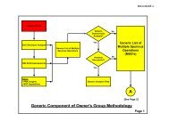
Figure 3-1 Deterministic Guidance Methodology Overview....................................................27<br />
Figure 3-2 Safe Shutdown System Selection and Path Development ......................................39<br />
Figure 3-3 Safe Shutdown Equipment Selection ......................................................................46<br />
Figure 3-4 Safe Shutdown Cable Selection ...............................................................................52<br />
Figure 3-5 Fire Area Assessment Flowchart .............................................................................58<br />
Figure 3.5.2-1 Open Circuit (Grounded Control Circuit)..............................................................65<br />
Figure 3.5.2-2 Short <strong>to</strong> Ground (Grounded Control Circuit) ........................................................67<br />
Figure 3.5.2-3 Short <strong>to</strong> Ground (Ungrounded Control Circuit) ....................................................68<br />
Figure 3.5.2-4 Hot Short Grounded Control Circuit).....................................................................71<br />
Figure 3.5.2-5 Hot Short (Ungrounded Control Circuit)................................................................72<br />
Figure 3.5.2-6 Common Power Source (Breaker Coordination) ...................................................73<br />
Figure 3.5.2-7 Inter-Cable with Ground Plane (Same Raceway) ..................................................73<br />
Figure 3.5.2-8 Inter- and Intra-Cable Hot Shorts ...........................................................................75<br />
Figure 3.5.2-9 Double Intra-Cable Hot Shorts ................................................................................75<br />
Figure 3.5.2-10 AC Power – Motive Power........................................................................................76<br />
Figure 3.5.2-11 DC Mo<strong>to</strong>r – Motive Power........................................................................................77<br />
Figure 3.5.2-12 Common Power Source (Breaker Coordination) ...................................................79<br />
Figure 4.1 Resolution Methodology............................................................................................85<br />
Figure 5-1 Simplified Process Diagram....................................................................................105<br />
Figure 5-2 Fragility Curves for Thermoset, Thermoplastic &Armored Cable....................124<br />
Figure B.1-1 Example MHIF Sequence .................................................................................... B.1-4<br />
Figure B.1-2 MHIF Analysis Flow Chart ................................................................................. B.1-6<br />
Figure B.1-3 Fault Current for Fire-Induced Cable Failure ................................................ B.1-12<br />
Figure B.1-4 Fault Resistance for Fire-Induced Cable Failure ............................................ B.1-13<br />
Figure B.1-5 Percent Faults Cleared for Specified Time – Thermoset Cable ..................... B.1-17<br />
Figure B.1-6 Percent Faults Cleared for Specified Time – Thermoplastic<br />
Cable .................................................................................................................... B.1-18<br />
Figure B.1-7 Probability of Clearing Fault Within Specified Time With 95%<br />
Uncertainty Bound Applied............................................................................... B.1-21<br />
Figure B.1-8 Insulation Resistance Values for Typical Test Series...................................... B.1-23<br />
Figure C-1 High/Low Pressure Interface Example..................................................................C-5<br />
Figure H-1 Required for Hot Shutdown and Important <strong>to</strong> SSD<br />
Components/Circuits...............................................................................................H-8<br />
TABLES Page #<br />
TABLE 5-1 Maxima for the Pairings F*P .................................................................................117<br />
TABLE 5-2 Maxima That Result from Maximum Credits for G (0.<strong>01</strong>), S (0.<strong>01</strong>),<br />
C (0.<strong>01</strong>) and Z (0.9)..................................................................................................117<br />
TABLE 5-3 Point Requirements for Screening .........................................................................118<br />
TABLE 5-4 Establishing Relative Risk Ranking When All Zones Preliminarily .................119<br />
Screen<br />
TABLE 5-5 Generic Location Fire Frequencies........................................................................120<br />
TABLE 5-6 Probabilities of Spurious Actuation Based on Cable Type and<br />
Failure Mode (Range) ............................................................................................121<br />
TABLE 5-7 General Fire Scenario Characterization Type Bins Mapped<br />
viii
<strong>to</strong> Fire Intensity Characteristics.............................................................................121<br />
TABLE 5-8 Total Unavailability Values for SSD Path-Based Screening CCDP....................122<br />
TABLE 5-9 Summary of the Probabilities (P SACD )....................................................................126<br />
TABLE B.1-0 Types Of Fire-Induced Circuit Failures Required <strong>to</strong> Be Considered............... B-19<br />
TABLE B.2-0 Evaluating the Impact of Fire-Induced Circuit Failures On A Safe<br />
Shutdown Component........................................................................................... B-26<br />
TABLE B.1-1 Fault Clearing Time ........................................................................................... B.1-14<br />
TABLE B.1-2 Probability of Clearing Faults Within a Specified Time................................. B.1-16<br />
TABLE B.1-3 Binomial Distribution 95% Confidence Fac<strong>to</strong>rs.............................................. B.1-20<br />
TABLE B.1-4 Fault Clearing Time 95% Lower Confidence Limit........................................ B.1-20<br />
TABLE F-1 <strong>NEI</strong> <strong>00</strong>-<strong>01</strong> MSO Identification Checklist............................................................... F-9<br />
TABLE G-1 BWR Generic MSO List .........................................................................................G-4<br />
TABLE G-2 PWR Generic MSO List........................................................................................G-27<br />
ix
GUIDANCE FOR POST-FIRE<br />
SAFE SHUTDOWN CIRCUIT ANALYSIS<br />
1 INTRODUCTION<br />
<strong>NEI</strong> <strong>00</strong>-<strong>01</strong>, <strong>Rev</strong>ision 3<br />
Oc<strong>to</strong>ber 2<strong>01</strong>1<br />
For some time there has been a need for a comprehensive industry guidance document for the<br />
performance of post-fire safe shutdown analysis <strong>to</strong> implement existing fire protection<br />
regulations. Such a document is needed <strong>to</strong> consistently apply the regula<strong>to</strong>ry requirements for<br />
post-fire safe shutdown analysis contained in 10 CFR 50.48 (Reference 7.4.1) and 10 CFR 50<br />
Appendix R (Reference 7.4.3).<br />
From the standpoint of deterministic safe shutdown analysis, Generic Letter 86-10 (Reference<br />
7.1.10) provided standardized answers <strong>to</strong> certain questions related <strong>to</strong> specific issues related <strong>to</strong><br />
this <strong>to</strong>pic. The answers provided, however, did not comprehensively address the entire subject<br />
matter. The lack of comprehensive guidance for post-fire safe shutdown analysis, in<br />
combination with the numerous variations in the approach used by the architect engineers<br />
responsible for each plant design, have resulted in wide variation in plant specific approaches <strong>to</strong><br />
deterministic post-fire safe shutdown analysis.<br />
Some of these approaches are based on long-held industry interpretations of the <strong>NRC</strong> regulations<br />
and guidance. In many cases, these interpretations were not documented in a manner that<br />
indicated a clear <strong>NRC</strong> acceptance of the position. In an <strong>NRC</strong> letter <strong>to</strong> <strong>NEI</strong> in early March 1997<br />
(Reference 7.4.30) <strong>NRC</strong> stated that the regula<strong>to</strong>ry requirements and staff positions are well<br />
documented, and that regula<strong>to</strong>ry requirements recognize that fires can induce multiple hot shorts.<br />
The industry responded (Reference 7.4.31) that industry and <strong>NRC</strong> staff interpretations of existing<br />
regulations and regula<strong>to</strong>ry guidance differ significantly on, at least, some aspects of the post-fire<br />
safe shutdown analysis requirements and provided reasons for these differing interpretations.<br />
The Boiling Water Reac<strong>to</strong>r Owners Group (BWROG) developed a comprehensive document for<br />
BWRs <strong>to</strong> compile deterministic safe shutdown analysis practices based on existing regula<strong>to</strong>ry<br />
requirements and guidance. That document was adopted in<strong>to</strong> <strong>NEI</strong> <strong>00</strong>-<strong>01</strong> with minor changes <strong>to</strong><br />
address PWR-specific safe shutdown analysis considerations.<br />
Changes were made in <strong>Rev</strong>ision 2 <strong>to</strong> provide an approach for addressing fire-induced multiple<br />
spurious operations (MSOs).<br />
Changes made in <strong>Rev</strong>ision 3 reflect an approach consistent with that endorsed by the <strong>NRC</strong> in<br />
Regula<strong>to</strong>ry Guide 1.189 <strong>Rev</strong>ision 2 and provide clarifications <strong>to</strong> licensee in-process questions<br />
while resolving the Multiple Spurious Operation (MSO) issue. <strong>Rev</strong>ision 3 also provides an<br />
update <strong>to</strong> the Generic MSO Lists in Appendix G. The list changes are as a result of the initial<br />
assessment of Appendix G by the Expert Panels at individual plants. The changes <strong>to</strong> the generic<br />
lists should be treated similar <strong>to</strong> other operating experience (OE) issues following the same<br />
process as the initial list.<br />
The <strong>NRC</strong> Staff position relative <strong>to</strong> the post-fire safe shutdown circuit guidance contained in <strong>NEI</strong><br />
<strong>00</strong>-<strong>01</strong> <strong>Rev</strong>ision 2 is stated in Regula<strong>to</strong>ry Guide 1.189 <strong>Rev</strong>ision 2. The <strong>NRC</strong> Staff stated in an<br />
1
<strong>NEI</strong> <strong>00</strong>-<strong>01</strong>, <strong>Rev</strong>ision 3<br />
Oc<strong>to</strong>ber 2<strong>01</strong>1<br />
Oc<strong>to</strong>ber 27, 2<strong>01</strong>0 meeting on <strong>NEI</strong> <strong>00</strong>-<strong>01</strong> <strong>Rev</strong>ision 3 that the regula<strong>to</strong>ry guide gives current Staff<br />
guidance as one acceptable way <strong>to</strong> meet the regulations. (Reference ML10328<strong>00</strong>72) Deviations<br />
from the guidance in Regula<strong>to</strong>ry Guide 1.189 <strong>Rev</strong>ision 2 should be appropriately evaluated and<br />
consistent with a plants current licensing basis.<br />
1.1 PURPOSE<br />
The purpose of this document is <strong>to</strong> provide a consistent process for performing a post-fire safe<br />
shutdown circuit analysis. While it describes differences between <strong>NRC</strong> and industry licensing<br />
positions, <strong>NEI</strong> <strong>00</strong>-<strong>01</strong> does not define what any plant’s licensing basis is or should be. Plant<br />
licensing bases have been developed over many years of licensee interactions with <strong>NRC</strong> staff,<br />
and the interpretation of these licensing bases is a matter between each licensee and <strong>NRC</strong> staff.<br />
The guidance provided in this document accounts for differences and uncertainties in licensing<br />
basis assumptions about circuit failures. It also provides, when used in conjunction with the<br />
pertinent sections of <strong>NRC</strong> Regula<strong>to</strong>ry Guide 1.189 <strong>Rev</strong>ision 2, a method for the resolution of the<br />
differences between the <strong>NRC</strong> and the industry related <strong>to</strong> fire-induced circuit failures resulting in<br />
MSOs.<br />
In general, the Industry has concluded that the treatment of MSO as outlined in this document is<br />
a new approach not previously used within the industry. It is aimed at providing a path <strong>to</strong><br />
closure for the differences of opinion between the <strong>NRC</strong> and the Industry relative <strong>to</strong> the treatment<br />
of fire-induced circuit failures and fire-induced spurious operation of plant equipment. As such,<br />
in aggregate, this specific resolution methodology is not part of any plant’s current licensing<br />
basis. As a whole, the resolution methodology for addressing MSO and the revised circuit<br />
failure criteria outlined in this document are considered <strong>to</strong> be beyond the current licensing basis<br />
(CLB) of operating plants. This conclusion is evidenced, in part, by the fact that <strong>NRC</strong><br />
Regulations on Fire Protection required one train <strong>to</strong> be free of fire damage and many of the MSO<br />
Scenarios involve damage <strong>to</strong> the non-credited train. His<strong>to</strong>rically, in both the licensing and<br />
inspection arenas, there is reasonable precedent for the single spurious criteria previously used<br />
within the Industry. Having said this, however, it is clear from the numerous meeting between<br />
the <strong>NRC</strong> and the Industry that the <strong>NRC</strong> Position is that MSOs should have always been<br />
considered in a Licensee’s Post-Fire Safe Shutdown Analysis. As a result, it is incumbent on<br />
each Licensee <strong>to</strong> understand their current licensing bases as it relates <strong>to</strong> this document, including<br />
the MSO resolution process. This document is a compilation of industry best practices that in<br />
some cases go beyond the guidance issued by the <strong>NRC</strong> related <strong>to</strong> post-fire safe shutdown.<br />
2
<strong>NEI</strong> <strong>00</strong>-<strong>01</strong>, <strong>Rev</strong>ision 3<br />
Oc<strong>to</strong>ber 2<strong>01</strong>1<br />
This document provides deterministic methods for addressing potential fire-induced circuit<br />
failure issues, either within or beyond the existing plant’s licensing basis, as determined by each<br />
licensee using their currently approved licensing basis for Fire Protection and Post-Fire Safe<br />
Shutdown. The deterministic method, derived from <strong>NRC</strong> regulations, guidance, and plant<br />
licensing bases is provided for analyzing and resolving circuit failure issues. Methods are<br />
provided <strong>to</strong> (1) select circuits and appropriate combinations thereof for the analysis of MSOs<br />
(note: the terms spurious actuation and spurious operation are considered synonymous. The term<br />
“spurious operation” is used in this document for consistency), and (2) determine the risk<br />
significance of identified circuit failure combinations, called MSOs. While the selection of<br />
circuit failure combinations, MSOs, has not traditionally been included in plant circuit analysis<br />
methods <strong>to</strong> date, it is appropriate <strong>to</strong> consider such combinations in the light of the results of<br />
recent cable failure testing, both EPRI/<strong>NEI</strong> and CAROLFIRE. The Resolution Methodology for<br />
MSOs included in this document will assist the licensee in determining whether potentially risksignificant<br />
interactions could impact safe shutdown, but this Resolution Methodology does not<br />
change the plant licensing basis. When an individual licensee’s licensing basis is either unclear<br />
or silent on the need <strong>to</strong> or method for addressing MSOs, the Resolution Methodology provides<br />
an industry consensus approach for addressing the issue. Each licensee must be prepared <strong>to</strong><br />
defend the integrity of their licensing basis relative <strong>to</strong> any actions taken <strong>to</strong> classify conditions<br />
relative <strong>to</strong> the resolution of the MSO issue as not being part of the current licensing basis. For<br />
MSOs determined <strong>to</strong> be beyond the CLB for a particular plant, risk insights, such as those<br />
contained in Chapter 5, may be used <strong>to</strong> assess the need for additional corrective actions. When<br />
using risk insights in this manner, however, each Licensee should provide a detailed explanation<br />
of the basis for concluding that the item is not a part of the Licensee’s CLB.<br />
The methods in this document do not require the systematic re-evaluation of a plant’s post-fire<br />
safe shutdown circuit analysis. A decision <strong>to</strong> perform such a systematic re-evaluation is entirely<br />
a licensee decision that may be based on <strong>NRC</strong> inspection findings, licensee self-assessment<br />
results, or industry experience. Neither do these methods take precedence over specific<br />
requirements accepted by the <strong>NRC</strong> in a plant’s post-fire safe shutdown analysis. In addition, this<br />
document provides criteria for assessing the risk significance of those MSO issues that may not<br />
be included in current safe shutdown analyses, but that may be a concern because of potential<br />
risk significance.<br />
The guidance in this document reflects the position that licensees should address potential risksignificant<br />
issues regardless of whether they involve compliance with the licensing basis. When<br />
issues are identified, the licensee should consider whether they involve violations of the licensing<br />
basis, are beyond the licensing basis, or are of uncertain compliance status and subject <strong>to</strong> possible<br />
disagreement with <strong>NRC</strong>. Licensees should also consider the risk significance of the findings<br />
consistent with the fire protection Significance Determination Process (SDP). Consideration of<br />
these parameters is illustrated in the following table:<br />
3
<strong>NEI</strong> <strong>00</strong>-<strong>01</strong>, <strong>Rev</strong>ision 3<br />
Oc<strong>to</strong>ber 2<strong>01</strong>1<br />
Action <strong>to</strong> Address Issue<br />
Type of Issue Issue Risk Significant Issue Not Risk Significant<br />
Issue outside Current<br />
Licensing Basis<br />
[CLB])<br />
Address in Corrective<br />
Action Program (CAP)<br />
Address in CAP or provide<br />
licensing basis changes<br />
(using approved regula<strong>to</strong>ry<br />
processes)<br />
Violation of CLB Address in CAP Address in CAP or provide<br />
licensing basis changes<br />
(using approved regula<strong>to</strong>ry<br />
processes)<br />
Compliance status/<br />
CLB not clear<br />
Address in CAP<br />
Address in CAP or provide<br />
licensing basis changes<br />
(using approved regula<strong>to</strong>ry<br />
processes)<br />
As seen in the table above, <strong>NEI</strong> <strong>00</strong>-<strong>01</strong> concludes that the licensees should address risksignificant<br />
circuit failure issues regardless of whether they involve potential violations. Issues<br />
that are both risk-insignificant and outside the licensing basis should be treated in accordance<br />
with current ROP guidelines as illustrated in the table. Low significance issues potentially<br />
involving compliance should be addressed consistent with current regula<strong>to</strong>ry guidelines;<br />
licensing basis changes (using approved regula<strong>to</strong>ry processes) may be in order, supported by the<br />
risk analysis performed using Section 5 risk analysis or the fire protection SDP methods.<br />
An example will illustrate the use of <strong>NEI</strong> <strong>00</strong>-<strong>01</strong>. In this example, assume that the licensee<br />
conducts a self-evaluation using this document and determines that he should postulate more than<br />
one simultaneous spurious operation in a certain fire area. Further, assume that the licensing basis<br />
is inconclusive. The licensee could determine the risk significance of the issue using the methods<br />
of <strong>NEI</strong> <strong>00</strong>-<strong>01</strong>, the revised fire protection Significance Determination Process, or other plant<br />
specific risk analyses. The licensee should place the issue in the plant Corrective Action Program<br />
(CAP) if it is significant according <strong>to</strong> the risk criteria used, or could request licensing basis<br />
changes (using approved regula<strong>to</strong>ry processes), or change the fire protection plan, if it is not. The<br />
compliance aspects would also be addressed in cases where it is not clear whether an issue is<br />
within the licensing basis (a “compliance issue”) or not.<br />
1.2 BACKGROUND<br />
<strong>Rev</strong>iewing past fire events can substantiate the uncertainty associated with the behavior of actual<br />
plant fires. On March 22, 1975, the Browns Ferry Nuclear Power Plant had the worst fire ever <strong>to</strong><br />
occur in a commercial nuclear power plant operating in the United States. (Reference U.S.<br />
Nuclear Regula<strong>to</strong>ry Commission (<strong>NRC</strong>) Inspection and Enforcement (IE) Bulletin Nos. 50-<br />
259/75 and 50-260/75-1, dated 2/25/75.) The Special <strong>Rev</strong>iew Group that investigated the<br />
Browns Ferry fire made two recommendations pertaining <strong>to</strong> assuring that the effectiveness of the<br />
fire protection programs at operating nuclear power plants conform <strong>to</strong> General Design Criterion<br />
(GDC) 3.<br />
The <strong>NRC</strong> should develop specific guidance for implementing GDC 3.<br />
4
<strong>NEI</strong> <strong>00</strong>-<strong>01</strong>, <strong>Rev</strong>ision 3<br />
Oc<strong>to</strong>ber 2<strong>01</strong>1<br />
<br />
The <strong>NRC</strong> should review the fire protection program at each operating plant, comparing<br />
the program <strong>to</strong> the specific guidance developed for implementing GDC 3.<br />
In response <strong>to</strong> the first recommendation, the <strong>NRC</strong> staff developed Branch Technical Position<br />
(BTP) Auxiliary Power Conversion Systems Branch (APCSB) 9.5-1, “Guidance for Fire<br />
Protection for Nuclear Power Plants," May 1, 1976; and Appendix A <strong>to</strong> BTP APCSB 9.5-1,<br />
“Guidelines for Fire Protection for Nuclear Power Plants Docketed Prior <strong>to</strong> July 1, 1976,"<br />
August 23, 1976. The guidance in these documents focused on the elements of fire protection<br />
defense-in-depth (DID): (1) prevention; (2) mitigation through the use of detection and<br />
suppression (au<strong>to</strong>matic and manual); (3) passive protection of structures, systems and<br />
components (SSCs) important <strong>to</strong> safety and post-fire safe shutdown.<br />
In response <strong>to</strong> the second recommendation, each operating plant compared its fire protection<br />
program with the guidelines of either BTP APCSB 9.5-1 or Appendix A <strong>to</strong> BTP APCSB 9.5-1.<br />
The staff reviewed the fire protection programs for compliance with the guidance.<br />
The guidance in BTP APCSB 9.5-1 and Appendix A <strong>to</strong> BTP APCSB 9.5-1, however, did not<br />
provide sufficiently specific guidance for performing post-fire safe shutdown analysis. Also,<br />
independent testing sponsored by the <strong>NRC</strong> indicated that some of the separation concepts<br />
proposed by licensees under the BTP, such as coating intervening cable trays with fire retardant<br />
coatings, would not provide sufficient protection in the event of a severe fire. Thirdly, some<br />
licensees did not implement aspects of the BTP that the <strong>NRC</strong> Staff considered essential in order<br />
<strong>to</strong> achieve adequate protection. To address these issue and <strong>to</strong> provide the necessary guidance,<br />
the <strong>NRC</strong> issued 10 CFR 50.48, “Fire Protection,” and Appendix R, “Fire Protection Program for<br />
Nuclear Power Facilities Operating Prior <strong>to</strong> January 1, 1979,” <strong>to</strong> 10 CFR Part 50 (45 FR 36082).<br />
The <strong>NRC</strong> published in the Federal Register (45 FR 76602) the final fire protection rule (10 CFR<br />
50.48) and Appendix R <strong>to</strong> 10 CFR Part 50 on November 19, 1980. The Appendix R Regulation<br />
required compliance with sections III.G, III.J, and III.O for all plants licensed <strong>to</strong> operate before<br />
January 1, 1979, and also required individual licensees <strong>to</strong> comply with other lettered sections,<br />
based on the status of their outstanding items under the BTP review, as reflected by <strong>NRC</strong><br />
correspondence <strong>to</strong> the individual licensees. Section III.G.2 of Appendix R reflected the results<br />
of the <strong>NRC</strong>'s independent cable tray fire testing program, overriding any previous approvals the<br />
<strong>NRC</strong> may have granted regarding the protection of cables with fire retardant coatings.<br />
This regulation applies <strong>to</strong> plants licensed <strong>to</strong> operate prior <strong>to</strong> January 1, 1979. For plants licensed<br />
<strong>to</strong> operate after January 1, 1979, the <strong>NRC</strong> staff, in most cases, required compliance with<br />
Appendix A <strong>to</strong> BTP APCSB 9.5-1 and Sections III.G, J & O of Appendix R. For these licensees,<br />
the sections of Appendix R apply <strong>to</strong> the plant as a licensing commitment, rather than as a legal<br />
requirement imposed by the code of federal regulations. Some other licensees provided<br />
comparisons <strong>to</strong> the guidelines of Section 9.5-1, “Fire Protection Program,” of NUREG-08<strong>00</strong>,<br />
“Standard <strong>Rev</strong>iew Plan,” which incorporated the guidance of Appendix A <strong>to</strong> BTP APCSB 9.5-1<br />
and the criteria of Appendix R, or BTP CMEB 9.5-1. Additionally, some plants had aspects of<br />
their programs reviewed <strong>to</strong> the criteria contained in Draft Regula<strong>to</strong>ry Guide 1.120 <strong>Rev</strong>ision 1<br />
(“Fire Protection Guidelines for Nuclear Power Plants,” November 1977), which primarily<br />
reflected the content of BTP APCSB 9.5-1 <strong>Rev</strong>ision 1. Therefore, even though fire protection<br />
programs can be essentially equivalent from plant <strong>to</strong> plant, the licensing basis upon which these<br />
programs are founded can be very different. Most plants licensed after January 1, 1979 have also<br />
5
<strong>NEI</strong> <strong>00</strong>-<strong>01</strong>, <strong>Rev</strong>ision 3<br />
Oc<strong>to</strong>ber 2<strong>01</strong>1<br />
been granted by the <strong>NRC</strong> a standard fire protection license condition allowing them <strong>to</strong> selfapprove<br />
and make changes <strong>to</strong> their <strong>NRC</strong> approved fire protection program provided such<br />
changes do not adversely affect the ability <strong>to</strong> achieve and maintain safe shutdown in the event of<br />
a fire. Therefore, even for plants with a common regula<strong>to</strong>ry basis traceable back <strong>to</strong> one of the<br />
regulations and/or guidance listed above, the details of implementing the fire protection program<br />
can be different.<br />
The plant design changes required for passive and active fire protection features and<br />
administrative controls required by the regulations discussed were fairly specific. These changes<br />
have been implemented throughout the industry. These changes have been effective in<br />
preventing a recurrence of a fire event of the severity experienced at Browns Ferry; have<br />
increased the likelihood that a fire will be detected rapidly and extinguished; and have reduced<br />
the potential consequences of a fire (see Appendix A for a brief his<strong>to</strong>ry of the Browns Ferry fire<br />
and a description of the fire protection improvements for nuclear plants since the Browns Ferry<br />
fire).<br />
To clarify the regulations, the <strong>NRC</strong> staff has issued numerous guidance documents in the form of<br />
Regula<strong>to</strong>ry Guides, memorandums, Regula<strong>to</strong>ry Issue Summaries, Generic Letters and<br />
Information Notices. These documents provide insights as <strong>to</strong> the <strong>NRC</strong> staff’s interpretation of<br />
the regulations, their views on acceptable methods for complying with the regulations, and<br />
clarification of the requirements for performing a post-fire safe shutdown analysis.<br />
1.3 OVERVIEW OF POST-FIRE SAFE SHUTDOWN ANALYSIS<br />
A fire in an operating nuclear power plant is a potentially serious event. In general, the<br />
likelihood of a large fire with the potential <strong>to</strong> damage plant equipment required for hot shutdown<br />
or important <strong>to</strong> safe shutdown is considered <strong>to</strong> be small. The expected fire would be contained in<br />
a single electrical panel or a localized portion of one room or area. Typical plant design<br />
segregates important cables and equipment from threats such as missiles, flooding, and<br />
significant fire sources. The expected plant response <strong>to</strong> this type of event would be <strong>to</strong> maintain<br />
continued operation and <strong>to</strong> dispatch the plant fire brigade <strong>to</strong> extinguish the fire.<br />
Despite this, the consequences of an event that damages plant equipment required for hot<br />
shutdown or important <strong>to</strong> safe shutdown can be significant. The concern is an “exposure fire,”<br />
capable of damaging multiple trains of SSC’s, despite the existing physical separation provided<br />
by criteria such as RG 1.75. The Browns Ferry fire resulted in damage <strong>to</strong> plant equipment<br />
important <strong>to</strong> safe shutdown. Although safe shutdown of the Browns Ferry unit was ultimately<br />
accomplished, the event was of sufficient significance <strong>to</strong> warrant major changes in fire protection<br />
design features of a nuclear power plant. Appendix A <strong>to</strong> this document provides a description of<br />
the improvements made in the fire protection design of nuclear power plants in response <strong>to</strong> the<br />
Browns Ferry fire event.<br />
In addition <strong>to</strong> plants making changes <strong>to</strong> the fire protection design features, they have also placed<br />
increased attention on identifying those systems and equipment important <strong>to</strong> the post-fire safe<br />
shutdown of each unit. A safe plant design is achieved by identifying the systems and equipment<br />
important <strong>to</strong> post-fire safe shutdown in each area of the plant; making conservative assumptions<br />
regarding the extent of fire damage; and assuring adequate separation of the redundant safe<br />
6
<strong>NEI</strong> <strong>00</strong>-<strong>01</strong>, <strong>Rev</strong>ision 3<br />
Oc<strong>to</strong>ber 2<strong>01</strong>1<br />
shutdown trains or protection of an alternative/dedicated shutdown train. When applied <strong>to</strong> the<br />
fire protection program of a nuclear power plant, these aspects of post-fire safe shutdown design,<br />
in combination with the other changes made in the design of the plant fire protection programs in<br />
response <strong>to</strong> the Browns Ferry fire, provide reasonable assurance that a plant fire will not prevent<br />
safe plant shutdown.<br />
The goal of post-fire safe shutdown is <strong>to</strong> assure that a single fire in any plant fire area will not<br />
result in any fuel cladding damage, rupture of the primary coolant boundary or rupture of the<br />
primary containment. This goal serves <strong>to</strong> prevent an unacceptable radiological release as a result<br />
of the fire. This goal is accomplished by assuring, in accordance with <strong>NRC</strong> Regula<strong>to</strong>ry<br />
requirements, the following deterministic criteria are satisfied for a single fire in any plant fire<br />
area:<br />
<br />
<br />
<br />
<br />
One safe shutdown path necessary <strong>to</strong> achieve and maintain hot shutdown is free of fire<br />
damage. The set of components necessary <strong>to</strong> achieve and maintain post-fire hot<br />
shutdown is referred <strong>to</strong> throughout this document as the “required for hot shutdown”.<br />
Potential fire-related impacts <strong>to</strong> components with the potential <strong>to</strong> mal-operate and<br />
adversely impact the ability of the safe shutdown path described above <strong>to</strong> perform its<br />
post-fire safe shutdown functions are prevented or can be adequately mitigated. The set<br />
of components whose mal-operation could impact the components on the required safe<br />
shutdown path in a particular fire area are referred <strong>to</strong> throughout this document as<br />
“important <strong>to</strong> safe shutdown”.<br />
Repairs <strong>to</strong> systems and equipment required <strong>to</strong> achieve and maintain cold shutdown can be<br />
accomplished within the required time frame.<br />
Any opera<strong>to</strong>r manual actions required <strong>to</strong> support achieving either hot or cold shutdown<br />
are identified and meet the applicable regula<strong>to</strong>ry acceptance requirements.<br />
The deterministic methods in Section 3 integrate the requirements and interpretations related <strong>to</strong><br />
post-fire safe shutdown in<strong>to</strong> a single location, and assure that these criteria are satisfied. These<br />
methods:<br />
<br />
<br />
<br />
Identify the systems, equipment and cables required <strong>to</strong> support the operation of each safe<br />
shutdown path.<br />
Identify the equipment and cables whose spurious operation could adversely impact the<br />
ability of these safe shutdown paths <strong>to</strong> perform their required safe shutdown function.<br />
Provide techniques <strong>to</strong> mitigate the effects of fire damage <strong>to</strong> components on or affecting<br />
the required safe shutdown path in each fire area.<br />
Using these methods <strong>to</strong> perform the post-fire safe shutdown analysis, in conjunction with the<br />
pertinent sections of Regula<strong>to</strong>ry Guide 1.189 <strong>Rev</strong>ision 2, will meet deterministic regula<strong>to</strong>ry<br />
requirements and provide an acceptable level of safety resulting in a safe plant design. These<br />
methods are consistent with the fire protection defense-in-depth concept that addresses<br />
uncertainties associated with the actual behavior of fires in a nuclear power plant. Post-fire safe<br />
shutdown is one part of each plant’s overall defense-in-depth fire protection program. The extent<br />
<strong>to</strong> which the requirements and guidance are applicable <strong>to</strong> a specific plant depends upon the age of<br />
7
<strong>NEI</strong> <strong>00</strong>-<strong>01</strong>, <strong>Rev</strong>ision 3<br />
Oc<strong>to</strong>ber 2<strong>01</strong>1<br />
the plant and the commitments established by the licensee in developing its fire protection<br />
program.<br />
The information contained in Sections 4 and 5 are provided for use in resolving the longstanding<br />
issues of MSOs. Using the Resolution Methodology described in these Sections and in the<br />
appendices referenced within Sections 4 and 5 is one way for a licensee <strong>to</strong> address the MSO issue.<br />
1.3.1 GENERAL METHODOLOGY DESCRIPTION<br />
The deterministic methodology described in this document can be used <strong>to</strong> perform a post-fire<br />
safe shutdown analysis <strong>to</strong> address the current regula<strong>to</strong>ry requirements. The Resolution<br />
Methodology for MSOs evaluates the risk significance of potential failures or combinations of<br />
failures. [Note: The term “MSOs” will be used throughout this document <strong>to</strong> denote one or<br />
more fire-induced component failures due <strong>to</strong> fire-induced circuit failures, including, but not<br />
limited <strong>to</strong> spurious operations resulting from hot shorts.] The baseline deterministic approach <strong>to</strong><br />
performing a post-fire safe shutdown analysis is contained in Sections 1, 2 and 3. Certain<br />
aspects of the deterministic approach, such as Alternate or Dedicated Shutdown under<br />
III.G.3/III.L and High/Low Pressure Interface Components have criteria slightly different from<br />
the baseline methodology. In an effort <strong>to</strong> provide as much clarity as possible and <strong>to</strong> not confuse<br />
the baseline approach with numerous exception statements, these areas with criteria differences<br />
have been addressed for their differences from the baseline criteria in appendices. High/Low<br />
Pressure Interfaces have been addressed in Appendix C. Alternate and Dedicated Shutdown has<br />
been addressed in Appendix D. The Resolution Methodology for addressing MSOs, which<br />
addresses a longstanding issue between the Industry and the <strong>NRC</strong>, is contained in Section 4,<br />
Appendix B, Appendix F and Appendix G. In an effort <strong>to</strong> clarify which fire-induced<br />
component impacts associated with flow diversions valves may be allowed <strong>to</strong> use opera<strong>to</strong>r<br />
manual actions, Appendix H has been added. Appendix H provides guidance related <strong>to</strong><br />
classifying components as either required for hot shutdown or important <strong>to</strong> safe shutdown.<br />
Appendix H is <strong>to</strong> be used in conjunction with Section 3 in making these classifications.<br />
Additionally, Appendix H is <strong>to</strong> be used <strong>to</strong> determine whether flow diversion valves which are<br />
initially classified as required for hot shutdown, can be re-classified as important <strong>to</strong> safe<br />
shutdown based on more detailed analysis. Appendix E provides additional guidance on<br />
opera<strong>to</strong>r manual actions. Finally, Section 5 contains information useful for assessing the risk<br />
associated with fire-induced circuit failures. Refer <strong>to</strong> Regula<strong>to</strong>ry Guide 1.189 <strong>Rev</strong>ision 2 <strong>to</strong><br />
determine which sections of this document have specific <strong>NRC</strong> endorsement.<br />
1.3.2 DETERMINISTIC METHOD<br />
When using the deterministic methodology described in Section 3 of this document <strong>to</strong> address<br />
the current regula<strong>to</strong>ry requirements, a basic assumption of the methodology is that there will be<br />
fire damage <strong>to</strong> systems and equipment located within a common fire area. The size and intensity<br />
of the fire required <strong>to</strong> cause this type of system and equipment damage is not determined.<br />
Rather, fire damage is assumed <strong>to</strong> occur regardless of the level of combustibles in the area, the<br />
ignition temperatures of any combustible materials, the lack of an ignition source or the presence<br />
of au<strong>to</strong>matic or manual fire suppression and detection capability. Fire damage is also postulated<br />
for all cables and equipment in the fire area that may be used for safe shutdown, even though<br />
most plant fire areas do not contain sufficient fire hazards for this <strong>to</strong> occur.<br />
8
<strong>NEI</strong> <strong>00</strong>-<strong>01</strong>, <strong>Rev</strong>ision 3<br />
Oc<strong>to</strong>ber 2<strong>01</strong>1<br />
It is with these basic and conservative assumptions regarding fire damage that use of the Section<br />
3 methodology begins. The methodology progresses by providing guidance on selecting systems<br />
and equipment needed for post-fire safe shutdown, on identifying the circuits of concern relative<br />
<strong>to</strong> these systems and equipment and on mitigating each fire-induced effect <strong>to</strong> the systems,<br />
equipment and circuits for the required safe shutdown path in each fire area. This methodology<br />
represents a comprehensive and safe approach for assuring that an operating plant can be safely<br />
shut down in the event of a single fire in any plant fire area. Section 3 also provides criteria for<br />
classifying components as required for hot shutdown or important <strong>to</strong> safe shutdown.<br />
To address the MSO issue, consideration is given <strong>to</strong> the MSO List in Appendix G and the circuit<br />
failure criteria contained in Appendix B. The circuit failure criteria contained in Appendix B,<br />
along with the implementation examples provided in Section 3.5, is intended for use with the<br />
MSO List in Appendix G and the MSO Resolution Methodology described in Section 4. Using<br />
the Resolution Methodology described in Section 4, a licensee can determine the potential fireinduced<br />
MSO impacts applicable <strong>to</strong> its facility. These potential fire-induced impacts can then be<br />
dispositioned using the deterministic methods described in Section 3 or, if appropriate, by using<br />
the risk-informed method described in Section 5. Additionally, fire modeling, as described in<br />
Section 4, may be used <strong>to</strong> assess whether or not a particular MSO in a particular location<br />
presents a potential impact <strong>to</strong> post-fire safe shutdown. In addressing MSOs, the conservative<br />
assumptions discussed above for the Section 3 analysis are not necessarily applied, e.g. fire<br />
modeling or risk assessment may be an acceptable resolution approach. The mitigating<br />
techniques available for use with any particular MSO is a function of whether that MSO is<br />
classified as being comprised of required for hot shutdown components or important <strong>to</strong> safe<br />
shutdown components. Refer <strong>to</strong> Appendix H for supplemental information on classifying<br />
components as either required for hot shutdown or important <strong>to</strong> safe shutdown components.<br />
Additionally, the MSOs listed in Appendix G are <strong>to</strong> be evaluated separately. Other than the<br />
cases described in Section 4, and as limited in Section 3.5, involving an evaluation by the Expert<br />
Panel of the need <strong>to</strong> combine MSOs, there is no need <strong>to</strong> evaluate for the combined effect of<br />
multiple MSOs. The potential affect of each MSO on post-fire safe shutdown is <strong>to</strong> be evaluated<br />
individually.<br />
In performing a deterministic post-fire safe shutdown analysis, the analyst must be cautious not<br />
<strong>to</strong> improperly apply the conservative assumptions described above. For example, one cannot<br />
rule out fire damage <strong>to</strong> unprotected circuits in a given fire area. This assumption is conservative<br />
only in terms of not being able <strong>to</strong> credit the systems and equipment associated with these circuits<br />
in support of post-fire safe shutdown. If the analyst, however, were <strong>to</strong> assume that these circuits<br />
were <strong>to</strong> be damaged by the fire when this provided an analytical advantage, this would be nonconservative.<br />
For example, assuming that fire damage results in a loss of offsite power may be<br />
non-conservative in terms of heat load, assumptions used in an analysis <strong>to</strong> determine the need for<br />
room cooling systems for the 72-hour fire coping period.<br />
The methodology for performing deterministic post-fire safe shutdown analysis is depicted in<br />
Figure 1-1. The specific steps are summarized in Sections 1.3.2.1 through 1.3.2.6, and discussed<br />
in depth in Section 3. The criteria for determining whether a component is a required for hot<br />
shutdown or important <strong>to</strong> safe shutdown component is contained in Section 3 and supplemented<br />
by Appendix H.<br />
9
<strong>NEI</strong> <strong>00</strong>-<strong>01</strong>, <strong>Rev</strong>ision 3<br />
Oc<strong>to</strong>ber 2<strong>01</strong>1<br />
1.3.2.1 Safe Shutdown Function Identification<br />
The goal of post-fire safe shutdown is <strong>to</strong> assure that a single fire in any single plant fire area will<br />
not result in any fuel cladding damage, rupture of the primary coolant boundary or rupture of the<br />
primary containment. This goal is accomplished by determining those functions important <strong>to</strong><br />
safely shutting down the reac<strong>to</strong>r and assuring that systems with the capability <strong>to</strong> perform these<br />
functions are not adversely impacted by a single fire in any plant fire area. The safe shutdown<br />
functions important <strong>to</strong> the plant are: (1) reactivity control; (2) pressure control; (3) inven<strong>to</strong>ry<br />
control; and (4) decay heat removal. To accomplish the required safe shutdown functions,<br />
certain support system functions (e.g., electrical power, ventilation) and process moni<strong>to</strong>ring<br />
capability (e.g., reac<strong>to</strong>r level, pressure indication) are also required.<br />
In addition, the analyst must assure that fire-induced spurious operations do not occur that can<br />
prevent equipment in the required safe shutdown path from performing its intended safe<br />
shutdown function. Examples of spurious operations that present a potential concern for the safe<br />
shutdown functions described above are those that can cause a: (1) loss of inven<strong>to</strong>ry in excess of<br />
the make up capability; (2) flow diversion or a flow blockage in the safe shutdown systems being<br />
used <strong>to</strong> accomplish the inven<strong>to</strong>ry control function; (3) flow diversion or a flow blockage in the<br />
safe shutdown systems being used <strong>to</strong> accomplish the decay heat removal function 1 .<br />
[BWR] Although an inadvertent reac<strong>to</strong>r vessel overfill condition is not a safe shutdown function<br />
listed above, the <strong>NRC</strong> has identified this as a concern. The acceptability of the current design<br />
features of the BWR <strong>to</strong> mitigate the effects of an inadvertent reac<strong>to</strong>r vessel overfill condition as a<br />
result of either a fire or equipment failure has been addressed by the BWROG in GE Report No.<br />
EDE 07—390 dated April 2, 1990, in response <strong>to</strong> <strong>NRC</strong> Generic Letter 89-19. The <strong>NRC</strong><br />
subsequently accepted the BWROG position in a Safety Evaluation dated June 9, 1994. Despite<br />
this, some of the MSOs listed in Appendix G for BWRs relate <strong>to</strong> an inadvertent reac<strong>to</strong>r vessel<br />
overfill. These will be addressed as a part of the MSO review.<br />
When performing a post-fire safe shutdown analysis, the decision as <strong>to</strong> whether <strong>to</strong> include<br />
specific components on the post-fire safe shutdown component list may be made by the use of<br />
thermal-hydraulic/transient analysis. If by use of a thermal-hydraulic/transient analysis, the<br />
worst-case failure of the component can be demonstrated <strong>to</strong> have no impact on the ability <strong>to</strong><br />
achieve and maintain post-fire hot shutdown, then the component need not be included on the<br />
post-fire safe shutdown component list and it need not be included in the post-fire safe shutdown<br />
analysis. The same is true of evaluations performed <strong>to</strong> address the MSOs contained in Appendix<br />
G <strong>to</strong> this document. When performing thermal-hydraulic/transient analysis in support of postfire<br />
safe shutdown impacts determinations, the criteria contained in Appendix H should be<br />
applied.<br />
Therefore, thermal-hydraulic/transient analysis is an acceptable basis for excluding plant<br />
components from consideration in the post-fire safe shutdown analysis. Similarly, thermalhydraulic/transient<br />
analysis is an acceptable basis for excluding a particular MSO from further<br />
consideration in a plant post-fire safe shutdown analysis. Finally, thermal-hydraulic/transient<br />
analysis coupled with a generic opera<strong>to</strong>r manual action(s) meeting all of the requirements of this<br />
1 Licensing Citation: Brown’s Ferry SER dated November 2, 1995 Section 3.7.3 third paragraph. Monticello<br />
Inspection report dated December 3, 1986 paragraph (2) page 16.<br />
10
<strong>NEI</strong> <strong>00</strong>-<strong>01</strong>, <strong>Rev</strong>ision 3<br />
Oc<strong>to</strong>ber 2<strong>01</strong>1<br />
document can be an acceptable way of addressing a potential impact <strong>to</strong> post-fire safe shutdown<br />
without including all of the affected cabling for a component or set of components in<strong>to</strong> the postfire<br />
safe shutdown analysis. The acceptance criteria and the set of acceptable initial conditions<br />
for the thermal hydraulic/transient analysis used in support of post-fire safe shutdown are<br />
contained in Appendix H. Best estimate/nominal values for the parameters used in the thermal<br />
hydraulic/transient analysis may be used as outlined in Appendix H. The use of these criteria<br />
allow the thermal hydraulic/transient analysis performed for the plant internal events PRA <strong>to</strong> be<br />
usable in assessing impacts and timelines for post-fire safe shutdown events when the postulated<br />
failure conditions are the same. Note that RG 1.189, Branch Technical Position 9.5.1 and<br />
Appendix R do not require postulation of a fire concurrent with any other Accident, Transient, or<br />
Severe Natural Phenomenon. For the Control Room fire, i.e. Appendix R Section III.G.3/III.L, a<br />
loss of offsite power must be postulated. The loss of offsite power, when postulated, however, is<br />
assumed <strong>to</strong> occur as an initial condition. There is no need <strong>to</strong> assume a delayed, i.e. postpostulated<br />
fire damage, loss of offsite power.<br />
11
<strong>NEI</strong> <strong>00</strong>-<strong>01</strong>, <strong>Rev</strong>ision 3<br />
Oc<strong>to</strong>ber 2<strong>01</strong>1<br />
12
<strong>NEI</strong> <strong>00</strong>-<strong>01</strong>, <strong>Rev</strong>ision 3<br />
Oc<strong>to</strong>ber 2<strong>01</strong>1<br />
1.3.2.2 Safe Shutdown System and Path Identification<br />
Using the safe shutdown functions described above, the analyst identifies a system or<br />
combination of systems with the ability <strong>to</strong> perform each of these shutdown functions. The<br />
systems are combined <strong>to</strong> form safe shutdown paths.<br />
1.3.2.3 Safe Shutdown Equipment Identification<br />
Using the Piping and Instrument Diagrams (P&IDs) for the mechanical systems comprising each<br />
safe shutdown path, the analyst identifies the mechanical equipment required for the operation of<br />
the system and the equipment whose spurious operation could affect the performance of the safe<br />
shutdown systems. Equipment that is required for the operation of a safe shutdown system for a<br />
particular safe shutdown path is related <strong>to</strong> that path (and is designated as a required hot shutdown<br />
component). Classifying components as required for hot shutdown is done in the absence of fire<br />
damage by reviewing the P&IDs and determining which components on the flow path are<br />
required <strong>to</strong> perform the required safe shutdown function, e.g. suction valve , pump, injection<br />
valve. Circuits required for the operation of components classified as required for hot shutdown<br />
must be protected in accordance with the requirements of Appendix R Section III.G.2. Note that<br />
if components on the initial flow path are found <strong>to</strong> be damaged by a fire in a particular fire area,<br />
then the components will need <strong>to</strong> be protected in that fire area, or another path selected as<br />
explained below.<br />
In some cases, after the initial selection of the required for hot shutdown components is made,<br />
the use of the protection schemes described in Appendix R Section III.G.2 will not be able <strong>to</strong> be<br />
used for all selected components, e.g. a required for hot shutdown component is physically<br />
located within a fire area where it is credited for post-fire safe shutdown. In these cases, a<br />
different set of required for hot shutdown components may need <strong>to</strong> be selected. This evolution<br />
of the selection of required for hot shutdown components is consistent with the criteria of<br />
making the selection in the absence of fire damage. The selection of components with the<br />
capability <strong>to</strong> perform the required for hot shutdown functions is made without considering fire<br />
damage. Once a component is classified as required for hot shutdown, it and its required<br />
circuitry, i.e. those circuits required for the operation of the component, must be protected from<br />
the effects of fires. If such protection is not feasible, then a different set of required for hot<br />
shutdown components may need <strong>to</strong> be selected until a set is found that can be assured <strong>to</strong> be free<br />
of fire damage in the fire area under consideration. If it is determined that protection of at least<br />
one redundant safe shutdown path from the effects of fire is not possible, then alternative or<br />
dedicated shutdown capability may be used in accordance with Appendix R Section III.G.3 (see<br />
Appendix D for details for alternative or dedicated shutdown capability).<br />
From a review of the associated P&IDs, the equipment that could spuriously operate as a result<br />
of fire-induced circuit damage and result in a flow blockage, a flow diversion (e.g., inven<strong>to</strong>ry<br />
makeup capability), loss of pressure control (due <strong>to</strong> overfeeding, excessive steam leakage, etc.),<br />
with the potential <strong>to</strong> impact the systems performing the required for hot shutdown functions, is<br />
identified. Similarly, this equipment is related <strong>to</strong> the particular safe shutdown path that it can<br />
affect. These components are classified as important <strong>to</strong> safe shutdown, unless they represent a<br />
13
<strong>NEI</strong> <strong>00</strong>-<strong>01</strong>, <strong>Rev</strong>ision 3<br />
Oc<strong>to</strong>ber 2<strong>01</strong>1<br />
potential flow diversion from the flow path for any system performing a required for hot<br />
shutdown function. Flow diversion components from the flow path for any system being used <strong>to</strong><br />
perform a required for hot shutdown function are initially classified as required for hot<br />
shutdown. They may be re-classified as important <strong>to</strong> safe shutdown based on further analysis<br />
using the criteria in Appendix H.<br />
The criteria in Section 3 and Appendix H is used by the analyst <strong>to</strong> classify the components<br />
identified above either as required for hot shutdown component or as an important <strong>to</strong> SSD<br />
component.<br />
The required safe shutdown path for any particular fire area is comprised of required for hot<br />
shutdown and important <strong>to</strong> SSD components. The classification for a particular component in<br />
regards <strong>to</strong> being either a required for hot shutdown or an important <strong>to</strong> SSD component can vary<br />
from fire area <strong>to</strong> fire area. Refer <strong>to</strong> Section 3 and Appendix H for additional details.<br />
The analyst reviews the P&IDs for the systems physically connected <strong>to</strong> the reac<strong>to</strong>r vessel <strong>to</strong><br />
determine the equipment that can result in a loss of reac<strong>to</strong>r inven<strong>to</strong>ry in excess of make up<br />
capability. This includes a special class of valves known as “high/low pressure interfaces.”<br />
Refer <strong>to</strong> Appendix C for the special requirements associated with high/low pressure interface<br />
valves. Equipment in this category is typically related <strong>to</strong> all safe shutdown paths, since a loss of<br />
reac<strong>to</strong>r vessel inven<strong>to</strong>ry with an interfacing system LOCA outside of Containment would be a<br />
concern for any safe shutdown path. The classification criteria contained in Appendix H also<br />
applies <strong>to</strong> high/low pressure interface components.<br />
1.3.2.4 Safe Shutdown Cable Identification<br />
Using the electrical schematic drawings for the equipment identified above, the analyst identifies<br />
all the cables required for the proper operation of the safe shutdown equipment. This will<br />
include, in addition <strong>to</strong> the cables that are physically connected <strong>to</strong> the equipment, any cables<br />
interlocked <strong>to</strong> the primary electrical circuit schematic through secondary circuit schematics. The<br />
cables identified are related <strong>to</strong> the same safe shutdown path as the equipment they support.<br />
14
<strong>NEI</strong> <strong>00</strong>-<strong>01</strong>, <strong>Rev</strong>ision 3<br />
Oc<strong>to</strong>ber 2<strong>01</strong>1<br />
While reviewing the electrical schematics for the equipment, the analyst identifies the safe<br />
shutdown equipment from the electrical distribution system (EDS). The EDS equipment (bus)<br />
for the safe shutdown path is associated with the equipment that it powers. All upstream busses<br />
are identified and similarly related <strong>to</strong> the safe shutdown path. In addition, all power cables<br />
associated with each bus in the EDS are identified and related <strong>to</strong> the same safe shutdown path as<br />
the EDS equipment. This information is required <strong>to</strong> support the Breaker Coordination Analysis.<br />
1.3.2.5 Safe Shutdown Circuit Analysis<br />
Using information on the physical routing of the required cables and the physical locations of all<br />
safe shutdown equipment, the analyst determines equipment and cable impacts for each safe<br />
shutdown path in each plant fire area. Based on the number and types of impacts <strong>to</strong> these paths,<br />
each fire area is assigned a required safe shutdown path(s). Initially, it is assumed that any<br />
cables related <strong>to</strong> a required safe shutdown component in a given fire area will cause the<br />
component <strong>to</strong> fail in the worst-case position (i.e. if the safe shutdown position of a valve is<br />
closed, the valve is assumed <strong>to</strong> open if the required cable is routed in the fire area).<br />
If necessary, a detailed analysis of the cable for the specific effect of the fire on that safe<br />
shutdown path is performed. This is accomplished by reviewing each conduc<strong>to</strong>r in each of these<br />
cables for the effects of a hot short, a short-<strong>to</strong>-ground or an open circuit 2 (test results indicate that<br />
open circuits are not the initial fire-induced failure mode) and determining the impact on the<br />
required safe shutdown component. The impact is assessed in terms of the effect on the safe<br />
shutdown system, the safe shutdown path, the safe shutdown functions and the goal for post-fire<br />
safe shutdown.<br />
1.3.2.6 Safe Shutdown Equipment Impacts<br />
Using the process described above, the analyst identifies the potential impacts <strong>to</strong> safe shutdown<br />
equipment, systems, paths, and functions relied upon in each fire area, and then mitigate the<br />
effects on safe shutdown for each safe shutdown component impacted by the fire. The<br />
mitigating techniques must meet the regulations. For example, for required for hot shutdown<br />
components the mitigating techniques listed in Figure 1-1 for required hot shutdown components<br />
apply. For required for hot shutdown components, unless the available options of re-designing<br />
the systems and/or re-designing/re-routing the affected circuits and processing Exemption<br />
Requests or License Amendment Requests (LARs), the protection schemes of Appendix R<br />
Section III.G.2 must be applied. If the component, however, is classified as an important <strong>to</strong> SSD<br />
component, mitigating <strong>to</strong>ols in addition <strong>to</strong> those available for required safe shutdown<br />
components may be credited as an alternate <strong>to</strong> those available for required for safe shutdown<br />
components. Refer <strong>to</strong> Figure 1-1, Section 3 and Appendix H for additional details. One of the<br />
mitigating <strong>to</strong>ols for an important <strong>to</strong> SSD circuit component is the use of an opera<strong>to</strong>r manual<br />
action. If an opera<strong>to</strong>r manual action is relied upon as the mitigating <strong>to</strong>ol, then it must meet the<br />
2 Licensing Citation: Waterford III Submittal <strong>to</strong> NRR dated February 7, 1985, Item No. 5 on page 3. Susquehanna<br />
Steam Electric Station <strong>NRC</strong> Question 40.97 paragraph 3a. Wolf Creek/Callaway SSER 5 Section 9.5.1.5 second<br />
paragraph.<br />
15
<strong>NEI</strong> <strong>00</strong>-<strong>01</strong>, <strong>Rev</strong>ision 3<br />
Oc<strong>to</strong>ber 2<strong>01</strong>1<br />
regula<strong>to</strong>ry acceptance criteria related <strong>to</strong> opera<strong>to</strong>r manual actions. Refer <strong>to</strong> Appendix E for<br />
additional information related <strong>to</strong> the regula<strong>to</strong>ry acceptance criteria for opera<strong>to</strong>r manual actions.<br />
The process of identifying and mitigating impacts <strong>to</strong> the required safe shutdown path(s)<br />
described above is explained in more detail throughout this document.<br />
1.3.3 RISK SIGNIFICANCE METHODS<br />
The Resolution Methodology for determining the Plant Specific List of MSOs is contained in<br />
Section 4. Refer <strong>to</strong> Section 4 for additional details. The method details both the determination<br />
of applicable plant specific MSOs and the disposition/mitigation of the MSOs using either<br />
deterministic methods, Fire Modeling or risk (e.g. Focused Scope Fire PRA) methods. The use<br />
of risk significance methods, such as a focused-scope Fire PRA is documented in Section 5.<br />
16
<strong>NEI</strong> <strong>00</strong>-<strong>01</strong>, <strong>Rev</strong>ision 3<br />
Oc<strong>to</strong>ber 2<strong>01</strong>1<br />
2 APPENDIX R REQUIREMENTS AND CONSIDERATIONS<br />
This section provides a general overview of the Appendix R regula<strong>to</strong>ry requirements including<br />
the criteria for classifying the various shutdown methods. It describes the distinctions between<br />
redundant, alternative and dedicated shutdown capabilities and provides guidance for<br />
implementing these shutdown methods. In addition, the considerations dealing with a loss of<br />
offsite power and associated circuits are also discussed. Refer <strong>to</strong> Figure 2-1.<br />
2.1 REGULATORY REQUIREMENTS<br />
10 CFR 50 Appendix A, General Design Criterion 3 establishes the overarching goals of <strong>NRC</strong>'s<br />
fire protection requirements.<br />
Criterion 3 -- Fire Protection. Structures, systems, and components important <strong>to</strong> safety<br />
shall be designed and located <strong>to</strong> minimize, consistent with other safety requirements, the<br />
probability and effect of fires and explosions. Noncombustible and heat resistant<br />
materials shall be used wherever practical throughout the unit, particularly in locations<br />
such as the containment and control room. Fire detection and fighting systems of<br />
appropriate capacity and capability shall be provided and designed <strong>to</strong> minimize the<br />
adverse effects of fires on structures, systems, and components important <strong>to</strong> safety.<br />
Firefighting systems shall be designed <strong>to</strong> assure that their rupture or inadvertent operation<br />
does not significantly impair the safety capability of these structures, systems, and<br />
components.<br />
10 CFR 50.48 Appendix R establishes the regula<strong>to</strong>ry requirements for protecting structures,<br />
systems and components important <strong>to</strong> safety, in order <strong>to</strong> satisfy the first sentence of GDC 3.<br />
Appendix R Section III.G establishes the safe shutdown requirements <strong>to</strong> address the third level<br />
of defense-in-depth. Sections III.G.1 and III.G.2 discuss the requirements for “required for hot<br />
shutdown” and “important <strong>to</strong> safe shutdown” and Section III.G.3 discusses the requirements for<br />
“alternative or dedicated” shutdown. The requirements for each of these shutdown<br />
classifications will be considered separately.<br />
The following sections discuss the regulations and distinctions regarding redundant shutdown<br />
methods. Requirements specifically for alternative/dedicated shutdown methods that are<br />
different from those used for redundant shutdown methods are discussed in Appendix D <strong>to</strong> this<br />
document:<br />
17
<strong>NEI</strong> <strong>00</strong>-<strong>01</strong>, <strong>Rev</strong>ision 3<br />
Oc<strong>to</strong>ber 2<strong>01</strong>1<br />
Requirements for Redundant Safe Shutdown<br />
Section III.G.1 provides the requirements for fire protection of safe shutdown capability and<br />
states the following:<br />
III. G. Fire protection of safe shutdown capability.<br />
1. Fire protection features shall be provided for structures, systems, and components<br />
important <strong>to</strong> safe shutdown. These features shall be capable of limiting fire<br />
damage so that:<br />
a. One train of systems necessary <strong>to</strong> achieve and maintain hot shutdown conditions<br />
from either the control room or emergency control station(s) is free of fire<br />
damage; and<br />
b. Systems necessary <strong>to</strong> achieve and maintain cold shutdown from either the control<br />
room or emergency control station(s) can be repaired within 72 hours.<br />
18
<strong>NEI</strong> <strong>00</strong>-<strong>01</strong>, <strong>Rev</strong>ision 3<br />
Oc<strong>to</strong>ber 2<strong>01</strong>1<br />
Figure 2-1<br />
Appendix R Requirements Flowchart<br />
III.G.1 Fire protection<br />
features shall be provided<br />
for structures, systems,<br />
and components important<br />
<strong>to</strong> safe shutdown<br />
One train of systems<br />
necessary (or required)<br />
<strong>to</strong> achieve and maintain<br />
hot shutdown is free of<br />
fire damage (*)<br />
Systems necessary <strong>to</strong><br />
achieve and maintain cold<br />
shutdown from either the<br />
MCR or Emergency Control<br />
Stations can be repaired<br />
within 72 hours<br />
III.G.2 Ensure that one<br />
of the redundant trains<br />
is free of fire damage<br />
(*) by one of the<br />
following:<br />
Yes<br />
Are the cables or<br />
equipment located within<br />
the same fire area,<br />
protected by 3-hr fire<br />
barriers, outside primary<br />
containment?<br />
Identify and locate the cables and<br />
equipment, including associated nonsafety<br />
circuits that could prevent<br />
operation or cause mal-operation<br />
due <strong>to</strong> hot shorts, open circuits, or<br />
shorts <strong>to</strong> ground, of redundant trains<br />
of systems necessary <strong>to</strong> achieve and<br />
maintain hot shutdown<br />
No (***)<br />
Separation of cables and equipment<br />
including associated non-safety circuits<br />
of redundant trains by a horizontal<br />
distance of more than 20 feet with no<br />
intervening combustible or fire hazards.<br />
(**)<br />
Enclosure of cable and equipment<br />
including associated non-safety<br />
circuits of one redundant train in a<br />
fire barrier having a 1-hour rating<br />
(**)<br />
Separation of cables and equipment<br />
including associated non-safety<br />
circuits of redundant trains by a fire<br />
barrier having a 3-hour rating<br />
(**)<br />
Ensure that fire detec<strong>to</strong>rs and an<br />
au<strong>to</strong>matic fire suppression system are<br />
installed in the area.<br />
Does the protection of<br />
systems whose function<br />
is required for hot<br />
shutdown satisfy the<br />
requirement of III.G.2?<br />
Yes<br />
Refer <strong>to</strong> Appendix D for the<br />
requirements of<br />
Alternative/Dedicated Shutdown<br />
Capability<br />
III.G.3 Alternative or dedicated shutdown<br />
capability and its associated circuits,<br />
independent of cables, systems or<br />
components in the areas, room or zone<br />
under consideration, shall be provided.<br />
No<br />
Done<br />
(*)”Free of Fire Damage” is achieved when the structure, system or component under consideration is capable of performing its intended<br />
function from either the Control Room or the emergency control stations during and after the postulated fire, as needed<br />
(**) Exemption Requests, Deviation Requests, LARs, GL 86-10 Fire Hazards Evaluations or Fire Protection Design Change Evaluations may be<br />
developed as necessary.<br />
(***) For non-inerted containments, provide one of the protection methods identified in Appendix R Section III.G.2 (a), (b), or (c)or provide for<br />
20 ft separation with no intervening combustibles or fire hazards, fire detection and au<strong>to</strong>matic suppression, systems. or non-combustible radiant<br />
energy shields as specified in Appendix R Section III.G.2 (d), (e), or (f)<br />
19
<strong>NEI</strong> <strong>00</strong>-<strong>01</strong>, <strong>Rev</strong>ision 3<br />
Oc<strong>to</strong>ber 2<strong>01</strong>1<br />
In Section III.G.1 there are no functional requirements specifically itemized for the structures,<br />
systems or components. The only requirements identified are those <strong>to</strong> initially achieve and<br />
maintain hot shutdown and <strong>to</strong> subsequently achieve cold shutdown once any required repairs<br />
have been completed.<br />
Section III.G.1 establishes the requirement <strong>to</strong> ensure that adequate fire protection features exist<br />
for systems structures and components important <strong>to</strong> safe shutdown. This is the regula<strong>to</strong>ry basis<br />
for the classification of components important <strong>to</strong> safe shutdown. By Section III.G.1, components<br />
important <strong>to</strong> safe shutdown must have adequate fire protection features, but are not limited <strong>to</strong><br />
those options described in III.G.2. Adequate fire protection features includes the use of opera<strong>to</strong>r<br />
manual actions. Therefore, prior <strong>NRC</strong> acceptance of opera<strong>to</strong>r manual actions for components<br />
classified as important <strong>to</strong> safe shutdown is not required. Section III.G.1.a establishes the<br />
requirement for having one train of systems necessary <strong>to</strong> achieve and maintain hot shutdown be<br />
free of fire damage. Section III.G.1.a is the regula<strong>to</strong>ry basis for components classified as<br />
required for hot shutdown. Section III.G.1 presumes that some preexisting fire protection<br />
features have been provided, such as barriers (previously approved by the <strong>NRC</strong> under Appendix<br />
A <strong>to</strong> BTP APCSB 9.5-1).<br />
When considering the consequences of a fire in a given fire area during the evaluation of the<br />
safe-shutdown capabilities of the plant, licensees should demonstrate that one safe shutdown<br />
path, i.e. success path of SSCs, that can be used <strong>to</strong> bring the reac<strong>to</strong>r <strong>to</strong> hot-shutdown or hotstandby<br />
conditions remains free of fire damage. Some plant designs (those that use low-pressure<br />
systems for their success path) pass through hot shutdown in a short time and then proceed<br />
directly <strong>to</strong> cold shutdown. For the purpose of this document, the term “safe shutdown” will be<br />
used <strong>to</strong> indicate bringing a plant <strong>to</strong> safe-shutdown condition, either hot shutdown or cold<br />
shutdown (when low-pressure systems are used as the success path), as applicable <strong>to</strong> each reac<strong>to</strong>r<br />
design and as defined by the plant technical specifications. The analysis should also demonstrate<br />
that fire damage <strong>to</strong> one safe shutdown path, i.e. success path of SSCs, needed for achieving cold<br />
shutdown will be limited so that a success path will be returned <strong>to</strong> an operating condition within<br />
72 hours, or for areas requiring alternative or dedicated shutdown, the licensee should<br />
demonstrate that cold-shutdown capability can be res<strong>to</strong>red and cold shutdown achieved within 72<br />
hours. For reac<strong>to</strong>r designs that do not remain in hot shutdown for 72 hours, the analysis should<br />
demonstrate that a cold-shutdown condition can be achieved and maintained within the required<br />
period of time.<br />
Equipment used for cold shutdown only is neither classified as required for hot shutdown nor<br />
important <strong>to</strong> safe shutdown. The only requirement associated with equipment used for cold<br />
shutdown only is that fire protection features be provided so that the equipment, if damaged by<br />
an exposure fire, can be repaired within 72 hours. The basis for this is Appendix R Section<br />
III.G.1.b.<br />
III.G.2 Except as provided for in paragraph G.3 of this section, where cables or<br />
equipment, including associated non-safety circuits that could prevent operation<br />
or cause mal-operation due <strong>to</strong> hot shorts, open circuits, or shorts <strong>to</strong> ground, of<br />
redundant trains of systems necessary <strong>to</strong> achieve and maintain hot shutdown<br />
conditions are located within the same fire area outside of primary containment,<br />
20
<strong>NEI</strong> <strong>00</strong>-<strong>01</strong>, <strong>Rev</strong>ision 3<br />
Oc<strong>to</strong>ber 2<strong>01</strong>1<br />
one of the following means of ensuring that one of the redundant trains is free of<br />
fire damage shall be provided:<br />
a. Separation of cables and equipment and associated non-safety circuits of<br />
redundant trains by a fire barrier having a 3-hour rating. Structural steel<br />
forming a part of or supporting such fire barriers shall be protected <strong>to</strong> provide<br />
fire resistance equivalent <strong>to</strong> that required of the barrier;<br />
b. Separation of cables and equipment and associated non-safety circuits of<br />
redundant trains by a horizontal distance of more than 20 feet with no intervening<br />
combustible or fire hazards. In addition, fire detec<strong>to</strong>rs and au<strong>to</strong>matic fire<br />
suppression system shall be installed in the fire area; or<br />
c. Enclosure of cable and equipment and associated non-safety circuits of one<br />
redundant train in a fire barrier having a 1-hour rating. In addition, fire<br />
detec<strong>to</strong>rs and an au<strong>to</strong>matic fire suppression system shall be installed in the fire<br />
area;<br />
Inside non-inerted containments one of the fire protection means specified above or one<br />
of the following fire protection means shall be provided:<br />
d. Separation of cables and equipment and associated non-safety circuits of<br />
redundant trains by a horizontal distance of more than 20 feet with no intervening<br />
combustibles or fire hazards;<br />
e. Installation of fire detec<strong>to</strong>rs and an au<strong>to</strong>matic fire suppression system in the fire<br />
area; or<br />
f. Separation of cables and equipment and associated non-safety circuits of<br />
redundant trains by a noncombustible radiant energy shield.<br />
Section III.G.2 provides separation requirements that must be utilized where redundant trains are<br />
located in the same fire area. To comply with the regula<strong>to</strong>ry requirements in Section III.G.1 and<br />
2, the analyst must determine which fire barriers are needed <strong>to</strong> provide separation essential for<br />
safe shutdown. Those barriers previously reviewed and approved by the <strong>NRC</strong> under Appendix<br />
A <strong>to</strong> APCSB 9.5-1 may be credited, e.g. barriers evaluated as adequate for the hazard. Where<br />
redundant trains of systems necessary <strong>to</strong> achieve hot shutdown are located in the same fire area<br />
outside of primary containment, one must provide fire protection features consistent with the<br />
requirements of Section III.G.2.a, b, or c (III.G.2.d, e, and f are also acceptable options inside<br />
non-inerted containments) <strong>to</strong> protect structures, systems, components and cables for one train<br />
capable of achieving and maintaining hot shutdown conditions. One must also assure that any<br />
repairs required <strong>to</strong> equipment necessary <strong>to</strong> achieve and maintain cold shutdown, from either the<br />
MCR or emergency control station(s) can be made within 72 hours.<br />
Depending on a plant’s current licensing basis and Fire Protection License Condition,<br />
exemptions, or deviations, LARs or GL 86-10 fire hazards analyses and/or fire protection design<br />
change evaluations may be used <strong>to</strong> justify configurations that meet the underlying goals of<br />
Appendix R but not certain specific requirements.<br />
21
<strong>NEI</strong> <strong>00</strong>-<strong>01</strong>, <strong>Rev</strong>ision 3<br />
Oc<strong>to</strong>ber 2<strong>01</strong>1<br />
2.2 REGULATORY GUIDANCE ON ASSOCIATED CIRCUITS OF CONCERN<br />
2.2.1 To ensure that safe shutdown systems remain available <strong>to</strong> perform their intended<br />
functions, the post-fire safe shutdown analysis also requires that other failures be<br />
evaluated <strong>to</strong> ensure that the safe shutdown system functions are not defeated. The<br />
analysis requires that consideration be given <strong>to</strong> cable failures that may cause spurious<br />
operations resulting in unwanted conditions. Also, circuit failures resulting in the loss of<br />
support systems such as the electrical power supply from improperly coordinated circuit<br />
protective devices must be considered. As defined in Generic Letter 81-12, these types of<br />
circuits are collectively referred <strong>to</strong> as “Associated circuits of concern”. 3<br />
2.2.2 Associated circuits of concern need <strong>to</strong> be evaluated <strong>to</strong> determine if cable faults can<br />
prevent the operation or cause the mal-operation of redundant systems used <strong>to</strong> achieve<br />
and maintain hot shutdown or adversely affect the post-fire safe shutdown capability.<br />
From time <strong>to</strong> time, the <strong>NRC</strong> has issued Staff Positions (e.g., memorandum, Information<br />
Notices, Generic Letters, inspection findings) documenting their positions as <strong>to</strong> what<br />
systems they consider necessary <strong>to</strong> achieve and maintain hot shutdown conditions, as<br />
well as documenting what types of fire-induced faults should be considered credible for<br />
affecting these necessary systems.<br />
2.2.3 <strong>NRC</strong> GL 81-12, Fire Protection Rule (45 FR 76602, November 19, 1980), dated February<br />
20, 1981, provides additional clarification related <strong>to</strong> associated circuits of concern. With<br />
respect <strong>to</strong> these associated circuits of concern, GL 81-12 describes three types of<br />
associated circuits of concern. The Clarification of Generic Letter 81-12 defines<br />
associated circuits of concern as those cables and equipment that:<br />
a). Have a physical separation less than that required by Section III.G.2 of Appendix R,<br />
and:<br />
b). Have either:<br />
i) A common power source with the shutdown equipment (redundant or alternative)<br />
and the power source is not electrically protected from the circuit of concern by<br />
coordinated breakers, fuses, or similar devices, or<br />
ii) A connection <strong>to</strong> circuits of equipment whose spurious operation would adversely<br />
affect the shutdown capability (i.e., RHR/RCS isolation valves, ADS valves,<br />
PORVs, steam genera<strong>to</strong>r atmospheric dump valves, instrumentation, steam<br />
bypass, etc.), or<br />
iii) A common enclosure (e.g., raceway, panel, junction) with the shutdown cables<br />
(redundant and alternative) and,<br />
(1) are not electrically protected by circuit breakers, fuses or similar devices, or<br />
(2) will not prevent propagation of the fire in<strong>to</strong> the common enclosure.<br />
3 See the definition of “associated circuits of concern” in GL 81-12.<br />
22
<strong>NEI</strong> <strong>00</strong>-<strong>01</strong>, <strong>Rev</strong>ision 3<br />
Oc<strong>to</strong>ber 2<strong>01</strong>1<br />
Although protecting the fire-induced failures of associated circuits of concern is required,<br />
<strong>to</strong> reinforce that Generic Letter 81-12 simply provides guidance rather than requirements,<br />
the Clarification of Generic Letter 81-12 further states the following regarding<br />
alternatives for protecting the safe shutdown capability:<br />
The guidelines for protecting the safe shutdown capability from fire-induced failures of<br />
associated circuits are not requirements. These guidelines should be used only as<br />
guidance when needed. These guidelines do not limit the alternatives available <strong>to</strong> the<br />
licensee for protecting the safe shutdown capability. All proposed methods for protection<br />
of the shutdown capability from fire-induced failures will be evaluated by the [<strong>NRC</strong>] staff<br />
for acceptability.<br />
2.3 REGULATORY INTERPRETATION ON LOSS OF OFFSITE POWER<br />
2.3.1 The loss of offsite power has the potential <strong>to</strong> affect safe shutdown capability. In addition,<br />
the regula<strong>to</strong>ry requirements for offsite power differ between the redundant and<br />
alternative/dedicated shutdown capability. Therefore, consideration must be given for the<br />
loss of offsite power when evaluating its effect on safe shutdown. The Appendix R<br />
requirement <strong>to</strong> consider a loss of offsite power is specified in Section III.L.3 as follows:<br />
The shutdown capability for specific fire areas may be unique for each such area, or it<br />
may be one unique combination of systems for all such areas. In either case, the<br />
alternative shutdown capability shall be independent of the specific fire area(s) and shall<br />
accommodate post-fire conditions where offsite power is available and where offsite<br />
power is not available for 72 hours. Procedures shall be in effect <strong>to</strong> implement this<br />
capability.<br />
2.3.2 Alternative/dedicated systems must demonstrate shutdown capability where offsite power<br />
is available and where offsite power is not available for 72 hours. If such equipment and<br />
systems used prior <strong>to</strong> 72 hours after the fire will not be capable of being powered by both<br />
onsite and offsite electric power systems because of fire damage, an independent onsite<br />
power system shall be provided. Equipment and systems used after 72 hours may be<br />
powered by offsite power only.<br />
2.3.3 For redundant shutdown, offsite power may be credited if demonstrated <strong>to</strong> be free of fire<br />
damage, similar <strong>to</strong> other safe shutdown systems.<br />
2.3.4 If offsite power is postulated <strong>to</strong> be lost for a particular fire area, and is not needed for the<br />
required safe shutdown path for 72 hours, actions necessary for its res<strong>to</strong>ration are<br />
considered <strong>to</strong> be performed under the purview of the emergency response organization<br />
and do not require the development of specific recovery strategies or procedures in<br />
advance.<br />
2.3.5 Since in an actual fire event offsite power may or may not be available, the potential<br />
availability of offsite power should also be considered <strong>to</strong> confirm that it does not pose a<br />
23
<strong>NEI</strong> <strong>00</strong>-<strong>01</strong>, <strong>Rev</strong>ision 3<br />
Oc<strong>to</strong>ber 2<strong>01</strong>1<br />
more challenging condition. For example, additional electric heat loads may affect<br />
HVAC strategies.<br />
24
<strong>NEI</strong> <strong>00</strong>-<strong>01</strong>, <strong>Rev</strong>ision 3<br />
Oc<strong>to</strong>ber 2<strong>01</strong>1<br />
3 DETERMINISTIC METHODOLOGY<br />
This section discusses a generic deterministic methodology and criteria that licensees can use <strong>to</strong><br />
perform a post-fire safe shutdown analysis <strong>to</strong> address regula<strong>to</strong>ry requirements. For a complete<br />
understanding of the deterministic requirements, work this section in combination with the<br />
information in Appendix C, High/Low Pressure Interfaces, Appendix D, Alternative and<br />
Dedicated Shutdown Requirements, Appendix E, Acceptance Criteria for Opera<strong>to</strong>r Manual<br />
Actions and repairs, and Appendix H, Hot Shutdown versus Important <strong>to</strong> Safe Shutdown<br />
Components. To resolve the industry issue related <strong>to</strong> MSOs, refer <strong>to</strong> Section 4, Appendix B,<br />
Appendix F and Appendix G. The plant specific analysis approved by <strong>NRC</strong> is reflected in the<br />
plant’s licensing basis. The methodology described in this section is an acceptable method of<br />
performing a post-fire safe shutdown analysis. This methodology is depicted in Figure 3-1.<br />
Other methods acceptable <strong>to</strong> <strong>NRC</strong> may also be used. Regardless of the method selected by an<br />
individual licensee, the criteria and assumptions provided in this guidance document may apply.<br />
The methodology described in Section 3 is based on a computer database oriented approach,<br />
which is utilized by several licensees <strong>to</strong> model Appendix R data relationships. This guidance<br />
document, however, does not require the use of a computer database oriented approach. The<br />
sections of this document accepted by the <strong>NRC</strong> are documented in Regula<strong>to</strong>ry Guide 1.189<br />
<strong>Rev</strong>ision 2.<br />
The requirements of Appendix R Sections III.G.1, III.G.2 and III.G.3 apply <strong>to</strong> equipment and<br />
cables required for achieving and maintaining safe shutdown in any fire area. Although<br />
equipment and cables for fire detection and suppression systems, communications systems and<br />
8-hour emergency lighting systems are important features, this guidance document does not<br />
address them. The requirements of Appendix R Section III.G.2 do not apply <strong>to</strong> the circuits for<br />
fire detection and suppression systems, communications systems and 8-hour emergency lighting<br />
systems.<br />
Additional information is provided in Appendix B <strong>to</strong> this document related <strong>to</strong> the circuit failure<br />
criteria <strong>to</strong> be applied in assessing impacts <strong>to</strong> post-fire safe shutdown, including MSOs. The<br />
criteria in Appendix B developed for MSOs has also been included in Section 3.5.1.1 for<br />
assessing the potential affects of fire-induced impacts <strong>to</strong> individual components on the required<br />
safe shutdown path for a particular III.G.1 and 2 fire area. Section 4 provides the Resolution<br />
Methodology for determining the Plant Specific List of MSOs <strong>to</strong> be evaluated. Section 5<br />
provides a focused-scope Fire PRA risk methodology for assessing, on an individual basis, the<br />
risk significance of any MSOs determined <strong>to</strong> be impacted within a common plant fire area. The<br />
appropriate use of these <strong>to</strong>ols for mitigating the effects of fire-induced circuit failures for this<br />
section and for the MSOs addressed in Section 4 and Appendix G are discussed in Appendix H.<br />
3.1 SAFE SHUTDOWN SYSTEMS AND PATH DEVELOPMENT<br />
This section discusses the identification of systems necessary <strong>to</strong> perform the required for hot<br />
shutdown or important <strong>to</strong> safe shutdown (SSD) functions. It also provides information on the<br />
process for combining these systems in<strong>to</strong> safe shutdown paths. Appendix R Section III.G.1.a<br />
requires that the capability <strong>to</strong> achieve and maintain hot shutdown be free of fire damage.<br />
25
<strong>NEI</strong> <strong>00</strong>-<strong>01</strong>, <strong>Rev</strong>ision 3<br />
Oc<strong>to</strong>ber 2<strong>01</strong>1<br />
Appendix R Section III.G.1.b requires that repairs <strong>to</strong> systems and equipment necessary <strong>to</strong><br />
achieve and maintain cold shutdown be completed within 72 hours. This section provides some<br />
guidance on classifying components as either required or important <strong>to</strong> SSD circuit components.<br />
It also provides some guidance on the <strong>to</strong>ols available for mitigating the effects of fire-induced<br />
circuit failures <strong>to</strong> each of these classes of equipment. For a supplemental discussion of the <strong>to</strong>pic<br />
of required for hot shutdown and important <strong>to</strong> SSD components refer <strong>to</strong> Appendix H.<br />
26
<strong>NEI</strong> <strong>00</strong>-<strong>01</strong>, <strong>Rev</strong>ision 3<br />
Oc<strong>to</strong>ber 2<strong>01</strong>1<br />
Figure 3-1<br />
Deterministic Guidance Methodology Overview<br />
Section 2.0<br />
Establish Appendix R Requirements<br />
Regula<strong>to</strong>ry Requirements<br />
Regula<strong>to</strong>ry Guidance on Associated Circuits of<br />
concern<br />
Regula<strong>to</strong>ry Interpretation on Loss of Offsite Power<br />
Section 3.3<br />
Select Safe Shutdown Cables<br />
Identify cables required for operation or that can<br />
cause mal-operation of listed equipment including<br />
improperly coordinated power circuits.<br />
Associate cables <strong>to</strong> equipment<br />
Locate cable raceway & endpoints by fire area<br />
Join data & identify SSD cables & equipment by<br />
fire area<br />
Section 3.1<br />
Determine SSD Functions, Systems & Paths<br />
Reactivity Control, Pressure Control, Inven<strong>to</strong>ry<br />
Control, DHR, Process Moni<strong>to</strong>ring, Supporting<br />
Functions<br />
Include those that can defeat SSD<br />
• RPV/RCS Loss of Inven<strong>to</strong>ry (*)<br />
• Flow Diversion (*)/Blockage<br />
• Inven<strong>to</strong>ry Makeup System being used for<br />
SSD in FA<br />
• Decay Heat Removal being used for SSD in<br />
FA<br />
* In excess of required makeup<br />
Section 3.2<br />
Select Safe Shutdown Equipment<br />
Equipment that may perform or defeat SSD<br />
functions<br />
Section 3.4<br />
Fire Area Assessment<br />
Determine fire impact <strong>to</strong> equipment required for<br />
SSD functions and establish SSD path for each<br />
fire area.<br />
Evaluate effects of a hot short, open circuit, &<br />
short <strong>to</strong> ground on each conduc<strong>to</strong>r for each cable.<br />
Refer <strong>to</strong> Section 3.5 for Circuit Analysis Criteria.<br />
Develop Methods for Prevention or<br />
Mitigation<br />
Required for Hot Shutdown Components:<br />
1. Re-design or re-analyze the circuit or<br />
component <strong>to</strong> eliminate the concern<br />
2. Reroute Cable of Concern<br />
3. Protect Cable of Concern in accordance with<br />
III.G.2<br />
4. Develop Exemption<br />
5. Develop Deviation or LARs<br />
6. Perform GL 86-10 Fire Hazards Evaluation<br />
7. Enter Fire Protection Change Process<br />
8. Identify other equipment <strong>to</strong> perform same<br />
function<br />
Important <strong>to</strong> SSD Components:<br />
1. Perform an opera<strong>to</strong>r manual action<br />
2. Address using fire modeling or a focused-scope<br />
Fire PRA using the methods of Section 5 for<br />
MSO impacts (if permitted under current license<br />
conditions).<br />
27
<strong>NEI</strong> <strong>00</strong>-<strong>01</strong>, <strong>Rev</strong>ision 3<br />
Oc<strong>to</strong>ber 2<strong>01</strong>1<br />
The goal of post-fire safe shutdown is <strong>to</strong> assure that a one train of shutdown systems, structures,<br />
and components required <strong>to</strong> achieve hot shutdown remains free of fire damage for a single fire in<br />
any single plant fire area. This goal is accomplished by determining those functions required <strong>to</strong><br />
achieve and maintain hot shutdown. Safe shutdown systems are selected so that the capability <strong>to</strong><br />
perform these required functions is a part of each safe shutdown path. The functions required for<br />
post-fire safe shutdown generally include, but are not limited <strong>to</strong> the following:<br />
<br />
<br />
<br />
<br />
Reactivity control<br />
Pressure control systems<br />
Inven<strong>to</strong>ry control systems<br />
Decay heat removal systems<br />
Process moni<strong>to</strong>ring (as defined in <strong>NRC</strong> Information Notice 84-09)<br />
<br />
Support systems<br />
• Electrical power and control systems<br />
• Component Cooling systems<br />
• Component Lubrication systems<br />
These functions are of importance because they have a direct bearing on the safe shutdown goal<br />
of being able <strong>to</strong> achieve and maintain hot shutdown, which ensures the integrity of the fuel, the<br />
reac<strong>to</strong>r pressure vessel and the primary containment. If these functions are preserved, then the<br />
plant will be safe because the fuel, the reac<strong>to</strong>r and the primary containment will not be damaged.<br />
By assuring that this equipment is not damaged and remains functional, the protection of the<br />
health and safety of the public is assured.<br />
The components required <strong>to</strong> perform these functions are classified as required for hot shutdown<br />
components. These components are necessary and sufficient <strong>to</strong> perform the required safe<br />
shutdown functions in the absence of fire damage. Circuits required for the operation of<br />
components classified as required for hot shutdown must be protected in accordance with the<br />
requirements of Appendix R Section III.G.2. Note that if components on the flow path initially<br />
selected are found <strong>to</strong> be damaged by a fire in a particular fire area, then the components will<br />
need <strong>to</strong> be protected in that fire area, or another path selected as explained below.<br />
In some cases, after the initial selection of the required for hot shutdown components is made,<br />
the use of the protection schemes described in Appendix R Section III.G.2 will not be able <strong>to</strong> be<br />
used for all selected components, e.g. a required for hot shutdown component is physically<br />
located within a fire area where it is credited for post-fire safe shutdown. In these cases, a<br />
different set of required for hot shutdown components may need <strong>to</strong> be selected. This evolution<br />
of the selection of required for hot shutdown components is consistent with the criteria of<br />
making the selection in the absence of fire damage. If it is determined that protection of at least<br />
one redundant safe shutdown path from the effects of fire is not possible, then alternative or<br />
dedicated shutdown capability may be used in accordance with Appendix R Section III.G.3 (see<br />
Appendix D for details for alternative or dedicated shutdown capability)..<br />
In addition, flow diversions off of the main flow path for the systems performing the required for<br />
safe shutdown functions are initially classified as required for hot shutdown. This criterion is<br />
28
<strong>NEI</strong> <strong>00</strong>-<strong>01</strong>, <strong>Rev</strong>ision 3<br />
Oc<strong>to</strong>ber 2<strong>01</strong>1<br />
considered an exception since it involves consideration of fire-induced circuit damage in<br />
classifying components as required for hot shutdown. A subsequent evaluation using the criteria<br />
from Appendix H can be used <strong>to</strong> re-classify the flow diversion component as important <strong>to</strong> safe<br />
shutdown.<br />
Breakers for associated circuits of concern - common power supply should be coordinated or<br />
addressed by the licensee CLB in accordance with the guidance in Generic Letter 81-12<br />
clarification letter dated March 22, 1982.<br />
The two cases described above are the only two cases where fire damage is considered.<br />
Since fire-induced impacts <strong>to</strong> plant equipment/cables can occur in the fire condition, these<br />
impacts must be addressed. Those components not necessary <strong>to</strong> perform the required for hot<br />
shutdown functions, but which could be impacted by the fire and cause a subsequent impact <strong>to</strong><br />
the required for hot shutdown components are classified as important <strong>to</strong> SSD components.<br />
Depending on the classification of the components, the <strong>to</strong>ols available for mitigating the affects<br />
of fire-induced damage vary.<br />
The distinction between required for hot shutdown and important <strong>to</strong> safe shutdown, however, is a<br />
legal distinction related <strong>to</strong> the requirements in Appendix R Section III.G.1 and its legal<br />
relationship <strong>to</strong> Appendix R Section III.G.2. Required for hot shutdown components are not<br />
necessarily more critical <strong>to</strong> safe shutdown than important <strong>to</strong> safe shutdown components. Fireinduced<br />
damage <strong>to</strong> both required for hot shutdown and important <strong>to</strong> safe shutdown components<br />
must be appropriately addressed using a mitigating strategy appropriate <strong>to</strong> the significance of the<br />
fire-induced damage <strong>to</strong> post-fire safe shutdown.<br />
The available <strong>to</strong>ols are generally discussed in this section and in detail in Appendix H. The<br />
classification of a component or its power or control circuits may vary from fire area <strong>to</strong> fire area.<br />
Therefore, the required safe shutdown path for any given fire area is comprised of required for<br />
hot shutdown components and important <strong>to</strong> SSD components. The distinction and classification<br />
for components in each required safe shutdown path for each fire area should be discernible in<br />
the post-fire safe shutdown analysis.<br />
29
<strong>NEI</strong> <strong>00</strong>-<strong>01</strong>, <strong>Rev</strong>ision 3<br />
Oc<strong>to</strong>ber 2<strong>01</strong>1<br />
Generic Letter 81-12 specifies consideration of associated circuits of concern with the potential<br />
for spurious equipment operation and/or loss of power source, and the common enclosure<br />
failures. As described above, spurious operations/actuations can affect the accomplishment of<br />
the required safe shutdown functions listed above. Typical examples of the effects of the<br />
spurious operations of concern are the following:<br />
<br />
<br />
A loss of reac<strong>to</strong>r pressure vessel/reac<strong>to</strong>r coolant inven<strong>to</strong>ry in excess of the safe shutdown<br />
makeup capability<br />
A flow loss or blockage in the inven<strong>to</strong>ry makeup or decay heat removal systems being<br />
used for the required safe shutdown path.<br />
Spurious operations are of concern because they have the potential <strong>to</strong> directly affect the ability <strong>to</strong><br />
achieve and maintain hot shutdown, which could affect the fuel and cause damage <strong>to</strong> the reac<strong>to</strong>r<br />
pressure vessel or the primary containment. To address the issue of multiple spurious operations,<br />
Section 4 provides a Resolution Methodology for developing a Plant Specific List of MSOs for<br />
evaluation. Appendix B provides the circuit failure criteria applicable <strong>to</strong> the evaluation of the<br />
Plant Specific list of MSOs.<br />
Common power source and common enclosure concerns could also affect the safe shutdown path<br />
and must be addressed.<br />
In addition <strong>to</strong> the <strong>to</strong>ols described for components classified as required for hot shutdown, fireinduced<br />
impacts <strong>to</strong> cables and components classified as important <strong>to</strong> SSD may be mitigated<br />
using some additional <strong>to</strong>ols. For important <strong>to</strong> SSD component failures, opera<strong>to</strong>r manual actions,<br />
fire modeling and/or a focused-scope fire PRA may be used <strong>to</strong> mitigate the impact. (If the issue<br />
under evaluation is a part of a Licensee’s CLB and the use of a Focused-Scope Fire PRAs is not<br />
permitted in the Plants Current License Basis, then, a License Amendment Request (LAR) will<br />
be necessary <strong>to</strong> use the Focused-Scope Fire PRA).<br />
3.1.1 CRITERIA/ASSUMPTIONS<br />
The following criteria and assumptions should be considered, as applicable, when identifying<br />
systems available and necessary <strong>to</strong> perform the required safe shutdown functions and combining<br />
these systems in<strong>to</strong> safe shutdown paths. This list provides recognized examples of<br />
criteria/assumptions but should not be considered an all-inclusive list. The final set of<br />
criteria/assumptions should be based on regula<strong>to</strong>ry requirements and the performance criteria for<br />
post-fire safe shutdown for each plant.<br />
3.1.1.1 [BWR] GE Report GE-NE-T43-<strong>00</strong><strong>00</strong>2-<strong>00</strong>-<strong>01</strong>-R<strong>01</strong> entitled “Original Safe<br />
Shutdown Paths For The BWR” addresses the systems and equipment<br />
originally designed in<strong>to</strong> the GE boiling water reac<strong>to</strong>rs (BWRs) in the 1960s<br />
and 1970s, that can be used <strong>to</strong> achieve and maintain safe shutdown per<br />
Section III.G.1 of 10 CFR 50, Appendix R. Any of the shutdown paths<br />
(methods) described in this report are considered <strong>to</strong> be acceptable methods for<br />
achieving redundant safe shutdown.<br />
30
<strong>NEI</strong> <strong>00</strong>-<strong>01</strong>, <strong>Rev</strong>ision 3<br />
Oc<strong>to</strong>ber 2<strong>01</strong>1<br />
3.1.1.2 [BWR] GE Report GE-NE-T43-<strong>00</strong><strong>00</strong>2-<strong>00</strong>-03-R<strong>01</strong> provides a discussion on<br />
the BWR Owners' Group (BWROG) position regarding the use of Safety<br />
Relief Valves (SRVs) and low pressure systems (LPCI/CS) for safe shutdown.<br />
The BWROG position is that the use of SRVs and low pressure systems is an<br />
acceptable methodology for achieving redundant safe shutdown in accordance<br />
with the requirements of 10 CFR 50 Appendix R Sections III.G.1 and III.G.2.<br />
The <strong>NRC</strong> has accepted the BWROG position and issued an SER dated Dec.<br />
12, 2<strong>00</strong>0.<br />
3.1.1.3 [PWR] Generic Letter 86-10, Enclosure 2, Section 5.3.5 specifies that hot<br />
shutdown can be maintained without the use of pressurizer heaters (i.e.,<br />
pressure control is provided by controlling the makeup/charging pumps). Hot<br />
shutdown conditions can be maintained via natural circulation of the RCS<br />
through the steam genera<strong>to</strong>rs. The cooldown rate must be controlled <strong>to</strong><br />
prevent the formation of a bubble in the reac<strong>to</strong>r head. Therefore, feedwater<br />
(either auxiliary or emergency) flow rates as well as steam release must be<br />
controlled.<br />
3.1.1.4 The classification of shutdown capability as alternative/dedicated shutdown is<br />
made independent of the selection of systems used for shutdown.<br />
Alternative/dedicated shutdown capability is determined based on an inability<br />
<strong>to</strong> assure the availability of a redundant safe shutdown path. Compliance <strong>to</strong><br />
the separation requirements of Sections III.G.1 and III.G.2 may be<br />
supplemented by the use of opera<strong>to</strong>r manual actions <strong>to</strong> the extent allowed by<br />
the regulations and the licensing basis of the plant (see Appendix E), repairs<br />
(cold shutdown only), exemptions, deviations, GL 86-10 fire hazards analyses<br />
or fire protection design change evaluations permitted by GL 86-10, as<br />
appropriate. These may also be used in conjunction with alternative/dedicated<br />
shutdown capability.<br />
3.1.1.5 At the onset of the postulated fire, all safe shutdown systems (including<br />
applicable redundant trains) are assumed operable and available for post-fire<br />
safe shutdown. Systems are assumed <strong>to</strong> be operational with no repairs,<br />
maintenance, testing, Limiting Conditions for Operation, etc. in progress. The<br />
units are assumed <strong>to</strong> be operating at full power under normal conditions and<br />
normal lineups.<br />
3.1.1.6 No Final Safety Analysis Report accidents or other design basis events (e.g.<br />
loss of coolant accident, earthquake, station blackout), single failures, severe<br />
natural phenomenon (e.g., severe ultimate heat sink temperature) or non-fireinduced<br />
transients need be considered in conjunction with the fire.<br />
3.1.1.7 For the case of redundant shutdown, offsite power may be credited if<br />
demonstrated <strong>to</strong> be free of fire damage. Offsite power should be assumed <strong>to</strong><br />
remain available for those cases where its availability may adversely impact<br />
safety (i.e., reliance cannot be placed on fire causing a loss of offsite power if<br />
the consequences of offsite power availability are more severe than its<br />
31
<strong>NEI</strong> <strong>00</strong>-<strong>01</strong>, <strong>Rev</strong>ision 3<br />
Oc<strong>to</strong>ber 2<strong>01</strong>1<br />
presumed loss). No credit should be taken for a fire causing a loss of offsite<br />
power. For areas where train separation cannot be achieved and alternative<br />
shutdown capability is necessary, shutdown must be demonstrated both where<br />
offsite power is available and where offsite power is not available for 72<br />
hours.<br />
3.1.1.8 Post-fire safe shutdown systems and components are not required <strong>to</strong> be safetyrelated.<br />
3.1.1.9 The post-fire safe shutdown analysis assumes a 72-hour coping period starting<br />
with a reac<strong>to</strong>r scram/trip. Fire-induced impacts that provide no adverse<br />
consequences <strong>to</strong> hot shutdown within this 72-hour period need not be included<br />
in the post-fire safe shutdown analysis. At least one train can be repaired or<br />
made operable within 72 hours using onsite capability <strong>to</strong> achieve cold<br />
shutdown. Reasonable actions by the Nuclear Emergency Response<br />
Organization during the 72 hour coping period may be assumed <strong>to</strong> occur, if<br />
justifiable, e.g. actions <strong>to</strong> address room flooding.<br />
3.1.1.10 Manual initiation from the main control room or emergency control stations of<br />
systems required <strong>to</strong> achieve and maintain safe shutdown is acceptable where<br />
permitted by current regulations or approved by <strong>NRC</strong> (See Appendix E);<br />
au<strong>to</strong>matic initiation of systems selected for safe shutdown is not required but<br />
may be included as an option, if the additional cables and equipment are also<br />
included in the analysis. Spurious actuation of au<strong>to</strong>matic systems (Safety<br />
Injection, Auxiliary Feedwater, High Pressure Coolant Injection, Reac<strong>to</strong>r Core<br />
Isolation Cooling, etc.) due <strong>to</strong> fire damage, however, should be evaluated.<br />
3.1.1.11 Where a single fire can impact more than one unit of a multi-unit plant, the<br />
ability <strong>to</strong> achieve and maintain safe shutdown for each affected unit must be<br />
demonstrated (GDC 5).<br />
3.1.2 SHUTDOWN FUNCTIONS<br />
The following discussion on each of these shutdown functions provides guidance for selecting<br />
the systems and equipment required for hot shutdown. For additional information on BWR<br />
system selection, refer <strong>to</strong> GE Report GE-NE-T43-<strong>00</strong><strong>00</strong>2-<strong>00</strong>-<strong>01</strong>-R<strong>01</strong> entitled “Original Safe<br />
Shutdown Paths for the BWR.”<br />
3.1.2.1 Reactivity Control<br />
[BWR] Control Rod Drive System<br />
The primary means of accomplishing this post-fire safe shutdown function is<br />
either an au<strong>to</strong>matic or manual scram from the control room. The inherent<br />
design of RPS generally provides a high degree of assurance of a reac<strong>to</strong>r<br />
scram upon event initiation (GDC 23). In the unlikely event that a fire could<br />
adversely affect RPS prior <strong>to</strong> a scram, the safe shutdown performance and<br />
design requirements for the reactivity control function can be met without<br />
32
<strong>NEI</strong> <strong>00</strong>-<strong>01</strong>, <strong>Rev</strong>ision 3<br />
Oc<strong>to</strong>ber 2<strong>01</strong>1<br />
au<strong>to</strong>matic scram/trip capability. Manual scram/reac<strong>to</strong>r trip is credited. The<br />
post-fire safe shutdown analysis must only provide the capability <strong>to</strong> manually<br />
scram/trip the reac<strong>to</strong>r. Each licensee should have an opera<strong>to</strong>r manual action<br />
<strong>to</strong> either vent the instrument air header or <strong>to</strong> remove RPS power in their postfire<br />
safe shutdown procedures. The presence of this action precludes the need<br />
<strong>to</strong> perform circuit analysis for the reactivity control function and is an<br />
acceptable way <strong>to</strong> accomplish this function. [Refer <strong>to</strong> BWROG Report No.<br />
BWROG-TP-11-<strong>01</strong>1 <strong>Rev</strong>ision 0 June 2<strong>01</strong>1 NEDO-33638, BWROG<br />
Assessments of Generic Multiple Spurious Operations (MSOs) in Post-Fire<br />
Safe Shutdown Circuit Analysis for Operating BWR Plants.] Opera<strong>to</strong>rs are<br />
trained extensively on the use of the emergency operating procedures and<br />
performance of this action in an ATWS condition is always treated as a very<br />
high priority action. Shift manning must be adequate at all times for<br />
implementing the emergency operating procedures. Therefore, procedures<br />
coupled with opera<strong>to</strong>r training and the necessary staffing are always available<br />
<strong>to</strong> address this condition with the appropriate priority. The use of this<br />
criterion must be reconciled with the plant’s CLB.<br />
[PWR] Makeup/Charging<br />
There must be a method for ensuring that adequate shutdown margin is<br />
maintained from initial reac<strong>to</strong>r SCRAM <strong>to</strong> cold shutdown conditions, by<br />
controlling Reac<strong>to</strong>r Coolant System temperature and ensuring borated water is<br />
utilized for RCS makeup/charging.<br />
3.1.2.2 Pressure Control Systems<br />
The systems discussed in this section are examples of systems that can be<br />
used for pressure control. This does not restrict the use of other systems for<br />
this purpose.<br />
[BWR] Safety Relief Valves (SRVs)<br />
Initial pressure control may be provided by the SRVs mechanically cycling at<br />
their setpoints (electrically cycling for EMRVs). Mechanically-actuated<br />
SRVs require no electrical analysis <strong>to</strong> perform their overpressure protection<br />
function. The SRVs may also be opened <strong>to</strong> maintain hot shutdown conditions<br />
or <strong>to</strong> depressurize the vessel <strong>to</strong> allow injection using low pressure systems.<br />
These are operated manually. Au<strong>to</strong>matic initiation of the Au<strong>to</strong>matic<br />
Depressurization System (ADS) is not a required function. Au<strong>to</strong>matic<br />
initiation of the ADS may be credited, if available. If au<strong>to</strong>matic ADS is not<br />
available and use of ADS is desired, an alternative means of initiation of ADS<br />
separate from the au<strong>to</strong>matic initiation logic for accomplishing the pressure<br />
control function should be provided. If a high pressure system is selected for<br />
post-fire safe shutdown and if pressure is being controlled by the SRVs lifting<br />
on their spring set point, then ADS and SRVs would be classified as important<br />
<strong>to</strong> safe shutdown.<br />
33
<strong>NEI</strong> <strong>00</strong>-<strong>01</strong>, <strong>Rev</strong>ision 3<br />
Oc<strong>to</strong>ber 2<strong>01</strong>1<br />
[PWR] Makeup/Charging<br />
RCS pressure is controlled by controlling the rate of charging/makeup <strong>to</strong> the<br />
RCS. Although utilization of the pressurizer heaters and/or auxiliary spray<br />
reduces opera<strong>to</strong>r burden, neither component is required <strong>to</strong> provide adequate<br />
pressure control, but may be used. Pressure reductions are made by allowing<br />
the RCS <strong>to</strong> cool/shrink, thus reducing pressurizer level/pressure. Pressure<br />
increases are made by initiating charging/makeup <strong>to</strong> maintain pressurizer<br />
level/pressure or by using the pressurizer heaters. Manual initiation of the<br />
related pumps is acceptable.<br />
3.1.2.3 Inven<strong>to</strong>ry Control<br />
[BWR] Systems selected for the inven<strong>to</strong>ry control function should be capable<br />
of supplying sufficient reac<strong>to</strong>r coolant <strong>to</strong> achieve and maintain hot shutdown.<br />
Manual initiation of these systems is acceptable. Au<strong>to</strong>matic initiation<br />
functions are not required. Spurious actuation of au<strong>to</strong>matic systems, however,<br />
should be evaluated (High Pressure Coolant Injection, High Pressure Core<br />
Spray, Reac<strong>to</strong>r Core Isolation Cooling, etc.). If a low pressure system is<br />
selected for post-fire safe shutdown, then a sufficient number of SRVs or<br />
ADS Valves must be available <strong>to</strong> achieve and maintain reac<strong>to</strong>r pressure below<br />
the shu<strong>to</strong>ff head for the low pressure pumps. For this case, the SRVs or ADS<br />
would be required for hot shutdown components.<br />
[PWR]: Systems selected for the inven<strong>to</strong>ry control function should be capable<br />
of maintaining level <strong>to</strong> achieve and maintain hot shutdown. Typically, the<br />
same components providing inven<strong>to</strong>ry control are capable of providing<br />
pressure control. Manual initiation of these systems is acceptable. Au<strong>to</strong>matic<br />
initiation functions are not required. Spurious actuation of au<strong>to</strong>matic systems,<br />
however, should be evaluated (Safety Injection, High Pressure Injection,<br />
Auxiliary Feedwater, Emergency Feedwater, etc.).<br />
3.1.2.4 Decay Heat Removal<br />
[BWR] Systems selected for the decay heat removal function(s) should be<br />
capable of:<br />
<br />
<br />
<br />
Removing sufficient decay heat from primary containment, <strong>to</strong> prevent<br />
containment over-pressurization and failure.<br />
Satisfying the net positive suction head requirements of any safe shutdown<br />
systems taking suction from the containment (suppression pool).<br />
Removing sufficient decay heat from the reac<strong>to</strong>r <strong>to</strong> achieve cold<br />
shutdown. (This is not a hot shutdown requirement.)<br />
[PWR] Systems selected for the decay heat removal function(s) should be<br />
capable of:<br />
34
<strong>NEI</strong> <strong>00</strong>-<strong>01</strong>, <strong>Rev</strong>ision 3<br />
Oc<strong>to</strong>ber 2<strong>01</strong>1<br />
<br />
<br />
Removing sufficient decay heat from the reac<strong>to</strong>r <strong>to</strong> reach hot shutdown<br />
conditions. Typically, this entails utilizing natural circulation in lieu of<br />
forced circulation via the reac<strong>to</strong>r coolant pumps and controlling steam<br />
release via the Atmospheric Dump valves.<br />
Removing sufficient decay heat from the reac<strong>to</strong>r <strong>to</strong> reach cold shutdown<br />
conditions. (This is not a hot shutdown requirement.)<br />
This does not restrict the use of other systems.<br />
3.1.2.5 Process Moni<strong>to</strong>ring<br />
The process moni<strong>to</strong>ring function is provided for all safe shutdown paths. IN<br />
84-09, Attachment 1, Section IX “Lessons Learned from <strong>NRC</strong> Inspections of<br />
Fire Protection Safe Shutdown Systems (10 CFR 50 Appendix R)” provides<br />
guidance on the instrumentation acceptable <strong>to</strong> and preferred by the <strong>NRC</strong> for<br />
meeting the process moni<strong>to</strong>ring function. This instrumentation is that which<br />
moni<strong>to</strong>rs the process variables necessary <strong>to</strong> perform and control the functions<br />
specified in Appendix R Section III.L.1. Such instrumentation must be<br />
demonstrated <strong>to</strong> remain unaffected by the fire. The IN 84-09 list of process<br />
moni<strong>to</strong>ring is applied <strong>to</strong> alternative/dedicated shutdown (III.G.3). The use of<br />
this same list for III.G.2 redundant Post-Fire Safe Shutdown is acceptable, but<br />
the analyst needs <strong>to</strong> review the specific license basis for the plant under<br />
evaluation. In general, process moni<strong>to</strong>ring instruments similar <strong>to</strong> those listed<br />
below are needed <strong>to</strong> successfully use existing operating procedures (including<br />
Abnormal Operating Procedures).<br />
BWR<br />
<br />
<br />
<br />
<br />
<br />
Reac<strong>to</strong>r coolant level and pressure<br />
Suppression pool level and temperature<br />
Emergency or isolation condenser level<br />
Diagnostic instrumentation for safe shutdown systems<br />
Level indication for tanks needed for safe shutdown<br />
PWR<br />
<br />
<br />
<br />
<br />
<br />
<br />
Reac<strong>to</strong>r coolant temperature (hot leg / cold leg)<br />
Pressurizer pressure and level<br />
Neutron flux moni<strong>to</strong>ring (source range)<br />
Level indication for tanks needed for safe shutdown<br />
Steam genera<strong>to</strong>r level and pressure<br />
Diagnostic instrumentation for safe shutdown systems<br />
35
<strong>NEI</strong> <strong>00</strong>-<strong>01</strong>, <strong>Rev</strong>ision 3<br />
Oc<strong>to</strong>ber 2<strong>01</strong>1<br />
The specific instruments required may be based on opera<strong>to</strong>r preference, safe<br />
shutdown procedural guidance strategy (symp<strong>to</strong>matic vs. prescriptive), and<br />
systems and paths selected for safe shutdown.<br />
3.1.2.6 Support Systems<br />
3.1.2.6.1 Electrical Systems<br />
AC Distribution System<br />
Power for the Appendix R safe shutdown equipment is typically provided<br />
by a medium voltage system such as 4.16 KV Class 1E busses either<br />
directly from the busses or through step down transformers/load<br />
centers/distribution panels for 6<strong>00</strong>, 480 or 120 VAC loads. For redundant<br />
safe shutdown performed in accordance with the requirements of<br />
Appendix R Section III.G.1 and 2, power may be supplied from either<br />
offsite power sources or the emergency diesel genera<strong>to</strong>r depending on<br />
which has been demonstrated <strong>to</strong> be free of fire damage. No credit should<br />
be taken for any beneficial effects of a fire causing a loss of offsite power.<br />
Refer <strong>to</strong> Section 3.1.1.7.<br />
DC Distribution System<br />
Typically, the 125VDC distribution system supplies DC control power <strong>to</strong><br />
various 125VDC control panels including switchgear breaker controls.<br />
The 125VDC distribution panels may also supply power <strong>to</strong> the 120VAC<br />
distribution panels via static inverters. These distribution panels may<br />
supply power for instrumentation necessary <strong>to</strong> complete the process<br />
moni<strong>to</strong>ring functions.<br />
For fire events that result in an interruption of power <strong>to</strong> the AC electrical<br />
bus, the station batteries are necessary <strong>to</strong> supply any required control<br />
power during the interim time period required for the diesel genera<strong>to</strong>rs <strong>to</strong><br />
become operational. Once the diesels are operational, the 125VDC<br />
distribution system can be powered from sources feed from the diesels<br />
through the battery chargers.<br />
[BWR] Certain plants are also designed with a 250VDC Distribution<br />
System that supplies power <strong>to</strong> Reac<strong>to</strong>r Core Isolation Cooling and/or High<br />
Pressure Coolant Injection equipment.<br />
The DC control centers may also supply power <strong>to</strong> various small<br />
horsepower Appendix R safe shutdown system valves and pumps. If the<br />
DC system is relied upon <strong>to</strong> support safe shutdown without battery<br />
chargers being available, it must be verified that sufficient battery capacity<br />
exists <strong>to</strong> support the necessary loads for sufficient time (either until power<br />
is res<strong>to</strong>red, or the loads are no longer required <strong>to</strong> operate).<br />
36
<strong>NEI</strong> <strong>00</strong>-<strong>01</strong>, <strong>Rev</strong>ision 3<br />
Oc<strong>to</strong>ber 2<strong>01</strong>1<br />
3.1.2.6.2 Cooling Systems<br />
Various cooling water systems are required <strong>to</strong> support safe shutdown<br />
system operation, based on plant specific considerations. Typical uses<br />
include:<br />
<br />
<br />
<br />
RHR/SDC/DH Heat Exchanger cooling water<br />
Safe shutdown pump cooling (seal coolers, oil coolers)<br />
Diesel genera<strong>to</strong>r cooling<br />
3.1.2.6.3 HVAC Systems<br />
HVAC Systems are classified as important <strong>to</strong> safe shutdown.<br />
HVAC systems, however, are not needed <strong>to</strong> support post-fire safe<br />
shutdown in all cases. The need for HVAC system operation is based on<br />
plant specific configurations and plant specific heat loads. Typical<br />
potential uses include:<br />
<br />
<br />
<br />
<br />
Main control room, cable spreading room, relay room<br />
ECCS pump compartments<br />
Diesel genera<strong>to</strong>r rooms<br />
Switchgear rooms<br />
Plant specific evaluations are necessary <strong>to</strong> determine which HVAC<br />
systems could be needed <strong>to</strong> support post-fire safe shutdown. Transient<br />
temperature response analyses are often utilized <strong>to</strong> demonstrate that<br />
specific HVAC systems would or would not be needed. If HVAC systems<br />
are credited, the potential for adverse fire effects <strong>to</strong> the HVAC system<br />
must also be considered, including:<br />
<br />
<br />
Dampers closing due <strong>to</strong> direct fire exposure or due <strong>to</strong> hot gases<br />
flowing through ventilation ducts from the fire area <strong>to</strong> an area not<br />
directly affected by the fire. Where provided, smoke dampers should<br />
consider similar effects from smoke.<br />
Recirculation or migration of <strong>to</strong>xic conditions (e.g., smoke from the<br />
fire, suppressants such as Carbon Dioxide).<br />
In certain situations, adequate time exists <strong>to</strong> perform actions, such as<br />
opening doors or providing fans for temporary cooling, <strong>to</strong> allow continued<br />
equipment operation. Should a temperature analysis demonstrate that<br />
adequate time exists <strong>to</strong> perform actions, such as opening doors or<br />
providing fans for temporary cooling, this is an acceptable approach <strong>to</strong><br />
achieving HVAC Cooling. The temperature analysis must demonstrate<br />
the adequacy of the cooling effect from the selected action of opening<br />
doors or providing fans for temporary cooling within the specified time.<br />
37
<strong>NEI</strong> <strong>00</strong>-<strong>01</strong>, <strong>Rev</strong>ision 3<br />
Oc<strong>to</strong>ber 2<strong>01</strong>1<br />
The action of opening doors or installing temporary fans is not considered<br />
<strong>to</strong> be either a manual opera<strong>to</strong>r action or a repair.<br />
3.1.3 METHODOLOGY FOR SHUTDOWN SYSTEM SELECTION<br />
Refer <strong>to</strong> Figure 3-2 for a flowchart illustrating the various steps involved in selecting safe<br />
shutdown systems and developing the shutdown paths.<br />
The following methodology may be used <strong>to</strong> define the safe shutdown systems and paths for an<br />
Appendix R analysis:<br />
3.1.3.1 Identify safe shutdown functions<br />
<strong>Rev</strong>iew available documentation <strong>to</strong> obtain an understanding of the available<br />
plant systems and the functions required <strong>to</strong> achieve and maintain safe<br />
shutdown. Documents such as the following may be reviewed:<br />
<br />
<br />
<br />
<br />
<br />
<br />
<br />
Operating Procedures (Normal, Emergency, Abnormal)<br />
System descriptions<br />
Fire Hazard Analysis<br />
Single-line electrical diagrams<br />
Piping and Instrumentation Diagrams (P&IDs)<br />
[BWR] GE Report GE-NE-T43-<strong>00</strong><strong>00</strong>2-<strong>00</strong>-<strong>01</strong>-R02 entitled “Original<br />
Shutdown Paths for the BWR”<br />
Other NSSS Vendor Guidance<br />
38
<strong>NEI</strong> <strong>00</strong>-<strong>01</strong>, <strong>Rev</strong>ision 3<br />
Oc<strong>to</strong>ber 2<strong>01</strong>1<br />
Figure 3-2<br />
Safe Shutdown System Selection and Path Development<br />
Step 1<br />
Define Appendix R<br />
requirements.<br />
Refer <strong>to</strong> Figure 2-1<br />
Step 2<br />
Identify safe<br />
shutdown functions.<br />
Step 3<br />
Identify combinations of systems that<br />
satisfy each safe shutdown function.<br />
Additional<br />
support systems<br />
based on Step 4<br />
of Fig. 3-3<br />
Step 4<br />
Define combination of<br />
systems for each<br />
shutdown path.<br />
Step 5<br />
Assign shutdown path <strong>to</strong><br />
each combination of<br />
systems.<br />
Refer <strong>to</strong> Attachment 1<br />
for an example of a Safe<br />
Shutdown Path<br />
Development List.<br />
39
<strong>NEI</strong> <strong>00</strong>-<strong>01</strong>, <strong>Rev</strong>ision 3<br />
Oc<strong>to</strong>ber 2<strong>01</strong>1<br />
3.1.3.2 Identify Combinations of Systems That Satisfy Each Safe Shutdown<br />
Function<br />
Given the criteria/assumptions defined in Section 3.1.1, identify the available<br />
combinations of systems capable of achieving the safe shutdown functions of<br />
reactivity control, pressure control, inven<strong>to</strong>ry control, decay heat removal,<br />
process moni<strong>to</strong>ring and support systems such as electrical and cooling systems<br />
(refer <strong>to</strong> Section 3.1.2). This selection process does not restrict the use of<br />
other systems. In addition <strong>to</strong> achieving the required safe shutdown functions,<br />
consider other equipment whose mal-operation or spurious operation could<br />
impact the required safe shutdown function. The components in this latter set<br />
are classified as either required for hot shutdown or as important <strong>to</strong> SSD as<br />
explained in this section and in Appendix H.<br />
3.1.3.3 Define Combination of Systems for Each Safe Shutdown Path<br />
Select combinations of systems with the capability of performing all of the<br />
required safe shutdown functions and designate this set of systems as a safe<br />
shutdown path. In many cases, paths may be defined on a divisional basis<br />
since the availability of electrical power and other support systems must be<br />
demonstrated for each path. During the equipment selection phase, identify<br />
any additional support systems and list them for the appropriate path.<br />
3.1.3.4 Assign Shutdown Paths <strong>to</strong> Each Combination of Systems<br />
Assign a path designation <strong>to</strong> each combination of systems. The path will<br />
serve <strong>to</strong> document the combination of systems relied upon for safe shutdown<br />
in each fire area. Refer <strong>to</strong> Attachment 1 <strong>to</strong> this document for an example of a<br />
table illustrating how <strong>to</strong> document the various combinations of systems for<br />
selected shutdown paths.<br />
3.2 SAFE SHUTDOWN EQUIPMENT SELECTION<br />
The previous section described the methodology for selecting the systems and paths necessary <strong>to</strong><br />
achieve and maintain safe shutdown for an exposure fire event (see Section 6.0 DEFINITIONS<br />
for “Exposure Fire”). This section describes the criteria/assumptions and selection methodology<br />
for identifying the specific safe shutdown equipment necessary for the systems <strong>to</strong> perform their<br />
Appendix R functions. The selected equipment should be related back <strong>to</strong> the safe shutdown<br />
systems that they support and be assigned <strong>to</strong> the same safe shutdown path as that system. The<br />
list of safe shutdown equipment will then form the basis for identifying the cables necessary for<br />
the operation or that can cause the mal-operation of the safe shutdown systems. For each path it<br />
will be important <strong>to</strong> understand which components are classified as required safe shutdown<br />
components and which are classified as important <strong>to</strong> safe shutdown components. When<br />
evaluating the fire-induced impact <strong>to</strong> each affected cable/component in each fire area, this<br />
classification dictates the <strong>to</strong>ols available for mitigation the affects.<br />
40
<strong>NEI</strong> <strong>00</strong>-<strong>01</strong>, <strong>Rev</strong>ision 3<br />
Oc<strong>to</strong>ber 2<strong>01</strong>1<br />
3.2.1 CRITERIA/ASSUMPTIONS<br />
Consider the following criteria and assumptions when identifying equipment necessary <strong>to</strong><br />
perform the required safe shutdown functions:<br />
3.2.1.1 Safe shutdown equipment can be divided in<strong>to</strong> two categories. Equipment may<br />
be categorized as (1) primary components or (2) secondary components.<br />
Typically, the following types of equipment are considered <strong>to</strong> be primary<br />
components:<br />
<br />
Those mechanical devices, such as pumps, fans, valves, dampers,<br />
process instruments providing an input <strong>to</strong> a system control function<br />
and instruments credited for satisfying the process moni<strong>to</strong>ring safe<br />
shutdown function, are considered <strong>to</strong> be primary components for the<br />
purposes of this document.<br />
The electrical components, such as genera<strong>to</strong>rs, switchgear, load<br />
centers, mo<strong>to</strong>r control centers, batteries, inverters and distribution<br />
panels required <strong>to</strong> provide the motive or control power <strong>to</strong> mechanical<br />
components are defined as electrical distribution equipment and are<br />
also considered <strong>to</strong> be primary components for the purposes of this<br />
document.<br />
Secondary components are typically items found within the circuitry for a<br />
primary component. These provide a supporting role <strong>to</strong> the overall circuit<br />
function. Some secondary components may provide an isolation function or a<br />
signal <strong>to</strong> a primary component via either an interlock or input signal<br />
processor. Devices, such as relays, switches and mo<strong>to</strong>rs, necessary <strong>to</strong> support<br />
the functioning of the mechanical and electrical components are considered <strong>to</strong><br />
be secondary components for the purposes of this document. Breakers and<br />
mo<strong>to</strong>r starters required for the operation of mechanical component are<br />
considered <strong>to</strong> be subcomponents of the mechanical component.<br />
The distinction provided between primary and secondary components is not a<br />
required distinction for the post-fire safe shutdown analysis, but may be a<br />
necessary distinction when determining whether or not a particular MSO is<br />
beyond that requiring consideration given the number of components required<br />
<strong>to</strong> spuriously operate. Refer <strong>to</strong> Section 3.5.<br />
3.2.1.2 Assume that exposure fire damage <strong>to</strong> manual valves and piping does not<br />
adversely impact their ability <strong>to</strong> perform their pressure boundary or safe<br />
shutdown function (heat sensitive piping materials, including tubing with<br />
brazed or soldered joints, are not included in this assumption). Fire damage<br />
should be evaluated with respect <strong>to</strong> the ability <strong>to</strong> manually open or close the<br />
valve should this be necessary as a part of the post-fire safe shutdown<br />
scenario. For example, post-fire coefficients of friction for rising stem valves<br />
cannot be readily determined. Handwheel sizes and rim pulls are based on<br />
41
<strong>NEI</strong> <strong>00</strong>-<strong>01</strong>, <strong>Rev</strong>ision 3<br />
Oc<strong>to</strong>ber 2<strong>01</strong>1<br />
well lubricated stems. Any post-fire operation of a rising stem valve should<br />
be well justified using an engineering evaluation.<br />
3.2.1.3 Assume that all components, including manual valves, are in their normal<br />
position as shown on P&IDs or in the plant operating procedures, that there<br />
are no LCOs in effect, that the Unit is operating at 1<strong>00</strong>% power and that no<br />
equipment has been taken out of service for maintenance or surveillance.<br />
3.2.1.4 Assume that a check valve closes in the direction of potential flow diversion<br />
and seats properly with sufficient leak tightness <strong>to</strong> prevent flow diversion.<br />
Therefore, check valves do not adversely affect the flow rate capability of the<br />
safe shutdown systems being used for inven<strong>to</strong>ry control, decay heat removal,<br />
equipment cooling or other related safe shutdown functions.<br />
3.2.1.5 It is not necessary <strong>to</strong> consider the effects of fire-induced water hammer events<br />
affecting non-credited equipment. [Refer <strong>to</strong> BWROG Report No. BWROG-<br />
TP-11-<strong>01</strong>1 <strong>Rev</strong>sion 0 June 2<strong>01</strong>1 NEDO-33638.] This assumption is based on<br />
the conclusions of the NEDO-33638 prepared by the BWROG on Fire-<br />
Induced Water Hammer which states that the likely failure mode for water<br />
hammer events in Nuclear Power Plants does not include major rupture of the<br />
piping pressure boundary. The failures experienced that did affect the piping<br />
system pressure boundary include failures of vents or small branch lines, pipe<br />
cracks and pipe weld cracks.<br />
The primary concern for fire-induced water hammers in Nuclear Power Plants<br />
affecting non-credited equipment is the effects of subsequent flooding on the<br />
credited safe shutdown systems. Since this type of catastrophic failure was<br />
not evident in the water hammer studies perform in response <strong>to</strong> Unresolved<br />
Safety Issue (USI) A-1 and subsequent <strong>to</strong> that by EPRI in their Report on<br />
Water Hammer, the need <strong>to</strong> consider fire-induced water hammer in the postfire<br />
safe shutdown analysis affecting non-credited equipment is neither<br />
required nor warranted. This section applies <strong>to</strong> both BWRs and PWRs.<br />
3.2.1.6 In the absence of an engineering failure modes and effects analysis<br />
demonstrating conditions <strong>to</strong> the contrary, instruments (e.g., resistance<br />
temperature detec<strong>to</strong>rs, thermocouples, pressure transmitters, and flow<br />
transmitters) are assumed <strong>to</strong> fail upscale, midscale, or downscale as a result of<br />
fire damage, whichever is worse. An instrument performing a control<br />
function is assumed <strong>to</strong> provide an undesired signal <strong>to</strong> the control circuit.<br />
An instrument circuit engineering failure modes and effects analysis (FMEA)<br />
could consider fac<strong>to</strong>rs such as instrument loop bias, loop failure mode (i.e.,<br />
fail high or low on short <strong>to</strong> ground, short conduc<strong>to</strong>r-<strong>to</strong>-conduc<strong>to</strong>r, or open<br />
circuit) and normal loop position (i.e., controller dialed <strong>to</strong> the closed position<br />
which corresponds <strong>to</strong> low signal),as well as, the specific circuit and cable<br />
design for the instrument. [Refer <strong>to</strong> NUREG/CR-6776 and NUREG/CR-<br />
5546.]<br />
42
<strong>NEI</strong> <strong>00</strong>-<strong>01</strong>, <strong>Rev</strong>ision 3<br />
Oc<strong>to</strong>ber 2<strong>01</strong>1<br />
Other fac<strong>to</strong>rs <strong>to</strong> consider in a FMEA include but are not limited <strong>to</strong> the type of<br />
cable, i.e. shielded twisted pairs, cable insulation type, whether the necessary<br />
conduc<strong>to</strong>rs for the erroneous signal are within the same cable and the type of<br />
instrument and whether or not it is potentially damaged by the fire.<br />
3.2.2 METHODOLOGY FOR EQUIPMENT SELECTION<br />
Refer <strong>to</strong> Figure 3-3 for a flowchart illustrating the various steps involved in selecting safe<br />
shutdown equipment.<br />
Use the following methodology <strong>to</strong> select the safe shutdown equipment for a post-fire safe<br />
shutdown analysis:<br />
3.2.2.1 Identify the System Flow Path for Each Shutdown Path<br />
Mark up and annotate a P&ID <strong>to</strong> highlight the specific flow paths for each<br />
system in support of each shutdown path. Refer <strong>to</strong> Attachment 2 for an<br />
example of an annotated P&ID illustrating this concept. Determine which<br />
equipment should be included on the Safe Shutdown Equipment List (SSEL).<br />
As an option, include secondary components with a primary component(s)<br />
that would be affected by fire damage <strong>to</strong> the secondary component. By doing<br />
this, the SSEL can be kept <strong>to</strong> a manageable size and the equipment included<br />
on the SSEL can be readily related <strong>to</strong> required post-fire safe shutdown<br />
systems and functions.<br />
3.2.2.2 Identify the Equipment in Each Safe Shutdown System Flow Path<br />
Including Equipment That May Spuriously Operate and Affect System<br />
Operation<br />
<strong>Rev</strong>iew the applicable documentation (e.g. P&IDs, electrical drawings,<br />
instrument loop diagrams) <strong>to</strong> assure that all equipment in each system’s flow<br />
path has been identified. Assure that any equipment that could spuriously<br />
operate and adversely affect the desired system function(s) is also identified.<br />
Additionally, refer <strong>to</strong> Section 4 for the Resolution Methodology for<br />
determining the Plant Specific List of MSOs requiring evaluation. Criteria for<br />
making the determination as <strong>to</strong> which of these components are <strong>to</strong> be classified<br />
as required for hot shutdown or as important <strong>to</strong> SSD is contained in Section 3<br />
and in Appendix H. If additional systems are identified which are necessary<br />
for the operation of the safe shutdown system under review, include these as<br />
required for hot shutdown systems. Designate these new systems with the<br />
same safe shutdown path as the primary safe shutdown system under review<br />
(Refer <strong>to</strong> Figure 3-1).<br />
43
<strong>NEI</strong> <strong>00</strong>-<strong>01</strong>, <strong>Rev</strong>ision 3<br />
Oc<strong>to</strong>ber 2<strong>01</strong>1<br />
3.2.2.3 Develop a List of Safe Shutdown Equipment and Assign the<br />
Corresponding System and Safe Shutdown Path(s) Designation <strong>to</strong> Each.<br />
Prepare a table listing the equipment identified for each system and the<br />
shutdown path that it supports. Identify any valves or other equipment that<br />
could spuriously operate and impact the operation of that safe shutdown<br />
system. Criteria for making the determination as <strong>to</strong> which of these<br />
components are <strong>to</strong> be classified as required for hot shutdown or as important<br />
<strong>to</strong> SSD is contained in Section 3 and in Appendix H. Assign the safe<br />
shutdown path for the affected system <strong>to</strong> this equipment. During the cable<br />
selection phase, identify additional equipment required <strong>to</strong> support the safe<br />
shutdown function of the path (e.g., electrical distribution system equipment).<br />
Include this additional equipment in the safe shutdown equipment list.<br />
Attachment 3 <strong>to</strong> this document provides an example of a (SSEL). The SSEL<br />
identifies the list of equipment within the plant considered for post-fire safe<br />
shutdown and it documents various equipment-related attributes used in the<br />
analysis.<br />
Identify instrument tubing that may cause subsequent effects on instrument<br />
readings or signals as a result of fire. Determine and consider the fire area<br />
location of the instrument tubing when evaluating the effects of fire damage <strong>to</strong><br />
circuits and equipment in the fire area.<br />
3.2.2.4 Identify Equipment Information Required for the Safe Shutdown<br />
Analysis<br />
Collect additional equipment-related information necessary for performing the<br />
post-fire safe shutdown analysis for the equipment. In order <strong>to</strong> facilitate the<br />
analysis, tabulate this data for each piece of equipment on the SSEL. Refer <strong>to</strong><br />
Attachment 3 <strong>to</strong> this document for an example of a SSEL. Examples of<br />
related equipment data should include the equipment type, equipment<br />
description, safe shutdown system, safe shutdown path, drawing reference,<br />
fire area, fire zone, and room location of equipment. Other information such<br />
as the following may be useful in performing the safe shutdown analysis:<br />
normal position, hot shutdown position, cold shutdown position, failed air<br />
position, failed electrical position, high/low pressure interface concern, and<br />
spurious operation concern. Criteria for making the determination as <strong>to</strong> which<br />
of these components are <strong>to</strong> be classified as required for hot shutdown or as<br />
important <strong>to</strong> SSD is contained in Section 3 and in Appendix H.<br />
3.2.2.5 Identify Dependencies Between Equipment, Supporting Equipment, Safe<br />
Shutdown Systems and Safe Shutdown Paths.<br />
In the process of defining equipment and cables for safe shutdown, identify<br />
additional supporting equipment such as electrical power and interlocked<br />
equipment. As an aid in assessing identified impacts <strong>to</strong> safe shutdown,<br />
consider modeling the dependency between equipment within each safe<br />
44
<strong>NEI</strong> <strong>00</strong>-<strong>01</strong>, <strong>Rev</strong>ision 3<br />
Oc<strong>to</strong>ber 2<strong>01</strong>1<br />
shutdown path either in a relational database or in the form of a Safe<br />
Shutdown Logic Diagram (SSLD). Attachment 4 provides an example of a<br />
SSLD that may be developed <strong>to</strong> document these relationships.<br />
45
<strong>NEI</strong> <strong>00</strong>-<strong>01</strong>, <strong>Rev</strong>ision 3<br />
Oc<strong>to</strong>ber 2<strong>01</strong>1<br />
Figure 3-3<br />
Safe Shutdown Equipment Selection<br />
Step 1<br />
Define proposed shutdown<br />
paths.<br />
Step 2<br />
Identify the system flow path<br />
for each shutdown path.<br />
Refer <strong>to</strong> Attachment 2 for<br />
an example of an<br />
annotated P&ID.<br />
Step 3<br />
Identify combinations of<br />
equipment that satisfy each<br />
safe shutdown function.<br />
Step 4<br />
Is any equipment<br />
part of other<br />
systems?<br />
No<br />
Yes<br />
Additional<br />
equipment found<br />
from cable<br />
selection<br />
Refer <strong>to</strong> Step 5 in<br />
Fig. 3-4.<br />
Step 5<br />
Develop a list of safe shutdown<br />
equipment and assign the<br />
corresponding system and<br />
shutdown path(s).<br />
Step 6<br />
Identify equipment<br />
information related <strong>to</strong> the<br />
safe shutdown analysis.<br />
Refer <strong>to</strong><br />
Step 4 in<br />
Fig. 3-2.<br />
Refer <strong>to</strong> Attachment 3<br />
for an example of a<br />
Safe Shutdown<br />
Equipment List<br />
Step 7<br />
Identify dependencies<br />
between equipment, support<br />
equipment, systems and<br />
paths.<br />
Refer <strong>to</strong> Attachment 4<br />
for an example of a<br />
Safe Shutdown Logic<br />
Diagram<br />
46
<strong>NEI</strong> <strong>00</strong>-<strong>01</strong>, <strong>Rev</strong>ision 3<br />
Oc<strong>to</strong>ber 2<strong>01</strong>1<br />
3.3 SAFE SHUTDOWN CABLE SELECTION AND LOCATION<br />
This section provides industry guidance on one acceptable approach for selecting safe shutdown<br />
cables and determining their potential impact on equipment required for achieving and<br />
maintaining safe shutdown of an operating nuclear power plant for the condition of an exposure<br />
fire. The Appendix R safe shutdown cable selection criteria are developed <strong>to</strong> ensure that all<br />
cables that could affect the proper operation or that could cause the mal-operation of safe<br />
shutdown equipment are identified and that these cables are properly related <strong>to</strong> the safe shutdown<br />
equipment whose functionality they could affect. Through this cable-<strong>to</strong>-equipment relationship,<br />
cables become part of the safe shutdown path assigned <strong>to</strong> the equipment affected by the cable.<br />
The classification of a cable as either an important <strong>to</strong> SSD circuit cable or a required safe<br />
shutdown cable is also derived from the classification applied <strong>to</strong> the component that it supports.<br />
This classification can vary from one fire area <strong>to</strong> another depending on the approach used <strong>to</strong><br />
accomplish post-fire safe shutdown in the area. Refer <strong>to</strong> Section 3 and Appendix H for the<br />
criteria <strong>to</strong> be used for classifying required and important <strong>to</strong> SSD components.<br />
3.3.1 CRITERIA/ASSUMPTIONS<br />
To identify an impact <strong>to</strong> safe shutdown equipment based on cable routing, the equipment must<br />
have cables that affect it identified. Carefully consider how cables are related <strong>to</strong> safe shutdown<br />
equipment so that impacts from these cables can be properly assessed in terms of their ultimate<br />
impact on safe shutdown components, systems and functions.<br />
Consider the following criteria when selecting cables that impact safe shutdown equipment:<br />
3.3.1.1.1 The list of cables whose failure could impact the operation of a piece of<br />
safe shutdown equipment includes more than just those cables connected<br />
<strong>to</strong> the equipment. The relationship between cable and affected equipment<br />
is based on a review of the electrical or elementary wiring diagrams. To<br />
assure that all cables that could affect the operation of the safe shutdown<br />
equipment are identified, investigate the power, control, instrumentation,<br />
interlock, and equipment status indication cables related <strong>to</strong> the equipment.<br />
<strong>Rev</strong>iew additional schematic diagrams <strong>to</strong> identify additional cables for<br />
interlocked circuits that also need <strong>to</strong> be considered for their impact on the<br />
ability of the equipment <strong>to</strong> operate as required in support of post-fire safe<br />
shutdown. As an option, consider applying the screening criteria from<br />
Section 3.5 as a part of this section.<br />
3.3.1.1.2 In cases where the failure (including spurious operations) of a single cable<br />
could impact more than one piece of safe shutdown equipment, associate<br />
the cable with each piece of safe shutdown equipment.<br />
3.3.1.1.2.1 Electrical devices such as relays, switches and signal resis<strong>to</strong>r units<br />
are considered <strong>to</strong> be acceptable isolation devices. In the case of<br />
instrument loops and electrical metering circuits, review the<br />
47
<strong>NEI</strong> <strong>00</strong>-<strong>01</strong>, <strong>Rev</strong>ision 3<br />
Oc<strong>to</strong>ber 2<strong>01</strong>1<br />
isolation capabilities of the devices in the loop <strong>to</strong> determine that an<br />
acceptable isolation device has been installed at each point where<br />
the loop must be isolated so that a fault would not impact the<br />
performance of the safe shutdown instrument function. Refer <strong>to</strong><br />
Section 3.5 for the types of faults that should be considered when<br />
evaluating the acceptability of the isolation device being credited.<br />
3.3.1.1.3 Screen out cables for circuits that do not impact the safe shutdown<br />
function of a component (i.e., annuncia<strong>to</strong>r circuits, space heater circuits<br />
and computer input circuits) unless some reliance on these circuits is<br />
necessary. To be properly screened out, however, the circuits associated<br />
with these devices must be isolated from the component’s control scheme<br />
in such a way that a cable fault would not impact the performance of the<br />
circuit. Refer <strong>to</strong> Section 3.5 for the types of faults that should be<br />
considered when evaluating the acceptability of the isolation device being<br />
credited.<br />
3.3.1.1.4 For each circuit requiring power <strong>to</strong> perform its safe shutdown function,<br />
identify the cable supplying power <strong>to</strong> each safe shutdown and/or required<br />
interlock component. Initially, identify only the power cables from the<br />
immediate upstream power source for these interlocked circuits and<br />
components (i.e., the closest power supply, load center or mo<strong>to</strong>r control<br />
center). <strong>Rev</strong>iew further the electrical distribution system <strong>to</strong> capture the<br />
remaining equipment from the electrical power distribution system<br />
necessary <strong>to</strong> support delivery of power from either the offsite power<br />
source or the emergency diesel genera<strong>to</strong>rs (i.e., onsite power source) <strong>to</strong> the<br />
safe shutdown equipment. Add this equipment <strong>to</strong> the safe shutdown<br />
equipment list. The set of cables described above are classified as<br />
required safe shutdown cables. Evaluate the power cables for breaker<br />
coordination concerns. The non-safe shutdown cables off of the safe<br />
shutdown buses are classified as required for hot shutdown or as important<br />
<strong>to</strong> SSD based on the criteria contained in Section 3 and in Appendix H.<br />
3.3.1.1.4.1 The au<strong>to</strong>matic initiation logics for the credited post-fire safe<br />
shutdown systems are generally not required <strong>to</strong> support safe<br />
shutdown, although exceptions may exist where logic must remain<br />
intact <strong>to</strong> support the availability of a permissive, i.e. reac<strong>to</strong>r low<br />
pressure for LPCI injection, needed for component operation.<br />
Typically, each system can be controlled manually by opera<strong>to</strong>r<br />
actuation in the main control room or emergency control station.<br />
The emergency control station includes those plant locations where<br />
control devices, such as switches, are installed for the purpose of<br />
operating the equipment. If opera<strong>to</strong>r actions <strong>to</strong> manually<br />
manipulate equipment at locations outside the MCR or the<br />
emergency control station are necessary, those actions must<br />
conform <strong>to</strong> the regula<strong>to</strong>ry requirements on opera<strong>to</strong>r manual actions<br />
(See Appendix E). If not protected from the effects of fire, the<br />
48
<strong>NEI</strong> <strong>00</strong>-<strong>01</strong>, <strong>Rev</strong>ision 3<br />
Oc<strong>to</strong>ber 2<strong>01</strong>1<br />
fire-induced failure of au<strong>to</strong>matic initiation logic circuits should be<br />
considered for their potential <strong>to</strong> adversely affect any post-fire safe<br />
shutdown system function.<br />
3.3.1.1.5 Cabling for the electrical distribution system is a concern for those<br />
breakers that feed circuits and are not fully coordinated with upstream<br />
breakers. With respect <strong>to</strong> electrical distribution cabling, two types of<br />
cable associations exist. For safe shutdown considerations, the direct<br />
power feed <strong>to</strong> a primary safe shutdown component is associated with the<br />
primary component and classified as a required safe shutdown cable. For<br />
example, the power feed <strong>to</strong> a pump is necessary <strong>to</strong> support the pump.<br />
Similarly, the power feed from the load center <strong>to</strong> an MCC supports the<br />
MCC. However, for cases where sufficient branch-circuit coordination is<br />
not provided, the same cables discussed above would also support the<br />
power supply. For example, the power feed <strong>to</strong> the pump discussed above<br />
would support the bus from which it is fed because, for the case of a<br />
common power source analysis, the concern is the loss of the upstream<br />
power source and not the connected load. Similarly, the cable feeding the<br />
MCC from the load center would also be necessary <strong>to</strong> support the load<br />
center. Additionally, the non-safe shutdown circuits off of each of the<br />
required safe shutdown components in the electrical distribution system<br />
can impact safe shutdown if not properly coordinated. These cables are<br />
classified as required for hot shutdown based on the criteria contained in<br />
Section 3 and in Appendix H.<br />
3.3.1.1.6 Exclusion analysis may be used <strong>to</strong> demonstrate a lack of potential for any<br />
impacts <strong>to</strong> post-fire safe shutdown from a component or group of<br />
components regardless of the cable routing. For these cases, rigorous<br />
cable searching and cable <strong>to</strong> component associations may not be required.<br />
3.3.2 ASSOCIATED CIRCUIT OF CONCERN CABLES<br />
Appendix R, through the guidance provided in <strong>NRC</strong> Generic Letter 81-12, requires that<br />
separation features be provided for associated non-safety circuits that could prevent operation or<br />
cause mal-operation due <strong>to</strong> hot shorts, open circuits, or shorts <strong>to</strong> ground, of redundant trains of<br />
systems necessary <strong>to</strong> achieve hot shutdown. The three types of associated circuits were<br />
identified in Reference 7.1.5 and further clarified in a <strong>NRC</strong> memorandum dated March 22, 1982<br />
from R. Mattson <strong>to</strong> D. Eisenhut, Reference 7.1.6. They are as follows:<br />
Spurious actuations 4<br />
Common power source<br />
Common enclosure.<br />
4<br />
As explained in Appendix H, components whose spurious operations could directly prevent the required safe<br />
shutdown path in any fire area from performing its required hot shutdown function due <strong>to</strong> a flow diversion from<br />
the required flow path are initially classified as required for hot shutdown components. Components whose<br />
spurious operation could affect important <strong>to</strong> safe shutdown components might be associated circuits of concern<br />
for spurious actuation.<br />
49
<strong>NEI</strong> <strong>00</strong>-<strong>01</strong>, <strong>Rev</strong>ision 3<br />
Oc<strong>to</strong>ber 2<strong>01</strong>1<br />
Each of these cables is classified as an associated circuit of concern cable.<br />
Cables Whose Failure May Cause Spurious Operations<br />
Safe shutdown system spurious operation concerns can result from fire damage <strong>to</strong> a cable whose<br />
failure could cause the spurious operation/mal-operation of equipment whose operation could<br />
affect safe shutdown. These cables are identified in Section 3.3.3 <strong>to</strong>gether with the remaining<br />
safe shutdown cables needed <strong>to</strong> support control and operation of the equipment. As outlined in<br />
Appendix H, valves with the potential <strong>to</strong> cause flow diversions from the flow path credited <strong>to</strong><br />
perform a hot shutdown function are classified as required for hot shutdown unless they meet the<br />
criteria outlined in Appendix H<br />
Common Power Source Cables<br />
The concern for the common power source associated circuits of concern is the loss of a safe<br />
shutdown power source due <strong>to</strong> inadequate breaker/fuse coordination. In the case of a fireinduced<br />
cable failure on a non-safe shutdown load circuit supplied from the safe shutdown power<br />
source, a lack of coordination between the upstream supply breaker/fuse feeding the safe<br />
shutdown power source and the load breaker/fuse supplying the non-safe shutdown faulted<br />
circuit can result in loss of the safe shutdown bus. This would result in the loss of power <strong>to</strong> the<br />
safe shutdown equipment supplied from that power source preventing the safe shutdown<br />
equipment from performing its required safe shutdown function. Identify these cables <strong>to</strong>gether<br />
with the remaining safe shutdown cables required <strong>to</strong> support control and operation of the<br />
equipment. Refer <strong>to</strong> Section 3.5.2.4 for an acceptable methodology for analyzing the impact of<br />
these cables on post-fire safe shutdown.<br />
Common Enclosure Cables<br />
The concern with common enclosure associated circuits of concern is fire damage <strong>to</strong> a cable<br />
whose failure could propagate <strong>to</strong> other safe shutdown cables in the same enclosure either because<br />
the circuit is not properly protected by an isolation device (breaker/fuse) such that a fire-induced<br />
fault could result in ignition along its length, or by the fire propagating along the cable and in<strong>to</strong><br />
an adjacent fire area. This fire spread <strong>to</strong> an adjacent fire area could impact safe shutdown<br />
equipment in that fire area, thereby resulting in a condition that exceeds the criteria and<br />
assumptions of this methodology (i.e., multiple fires). Refer <strong>to</strong> Section 3.5.2.5 for an acceptable<br />
methodology for analyzing the impact of these cables on post-fire safe shutdown.<br />
3.3.3 METHODOLOGY FOR CABLE SELECTION AND LOCATION<br />
Refer <strong>to</strong> Figure 3-4 for a flowchart illustrating the various steps involved in selecting the cables<br />
necessary for performing a post-fire safe shutdown analysis.<br />
Use the following methodology <strong>to</strong> define the cables required for safe shutdown including cables<br />
that may be circuits of concerns for a post-fire safe shutdown analysis. Criteria for making the<br />
determination as <strong>to</strong> which circuits are <strong>to</strong> be classified as required for hot shutdown or as<br />
important <strong>to</strong> SSD is contained in Section 3 and in Appendix H.<br />
50
<strong>NEI</strong> <strong>00</strong>-<strong>01</strong>, <strong>Rev</strong>ision 3<br />
Oc<strong>to</strong>ber 2<strong>01</strong>1<br />
3.3.3.1 Identify Circuits Necessary for the Operation of the Safe Shutdown<br />
Equipment<br />
For each piece of safe shutdown equipment defined in section 3.2, review the<br />
appropriate electrical diagrams including the following documentation <strong>to</strong><br />
identify the circuits (power, control, instrumentation) required for operation or<br />
whose failure may impact the operation of each piece of equipment:<br />
<br />
<br />
<br />
<br />
Single-line electrical diagrams<br />
Elementary wiring diagrams<br />
Electrical connection diagrams<br />
Instrument loop diagrams.<br />
For electrical power distribution equipment such as power supplies, identify<br />
any circuits whose failure may cause a coordination concern for the bus under<br />
evaluation.<br />
If power is required for the equipment, include the closest upstream power<br />
distribution source on the safe shutdown equipment list. Through the iterative<br />
process described in Figures 3-2 and 3-3, include the additional upstream<br />
power sources up <strong>to</strong> either the offsite or the emergency power source.<br />
3.3.3.2 Identify Interlocked Circuits and Cables Whose Spurious Operation or<br />
Mal-operation Could Affect Shutdown<br />
In reviewing each control circuit, investigate interlocks that may lead <strong>to</strong><br />
additional circuit schemes, cables and equipment. Assign <strong>to</strong> the equipment<br />
any cables for interlocked circuits that can affect the equipment. Circuits<br />
feeding the interlocks in a components primary circuit are typically referred <strong>to</strong><br />
as secondary circuits.<br />
51
<strong>NEI</strong> <strong>00</strong>-<strong>01</strong>, <strong>Rev</strong>ision 3<br />
Oc<strong>to</strong>ber 2<strong>01</strong>1<br />
Figure 3-4<br />
Safe Shutdown Cable Selection<br />
Step 1<br />
Define safe shutdown equipment<br />
Refer <strong>to</strong> Figure 3-3<br />
Step 2<br />
Identify circuits (power, control,<br />
instrumentation) required for the operation<br />
of each safe shutdown equipment. (*)<br />
Step 3<br />
Identify equipment whose spurious<br />
operation or mal-operation could affect<br />
safe shutdown<br />
Step 4<br />
Identify interlocked circuits and cables<br />
whose failure may cause spurious<br />
actuations. (*)<br />
Step 5<br />
Is power required<br />
for equipment<br />
operation?<br />
Yes<br />
No<br />
Step 7<br />
Assign cables <strong>to</strong> equipment.<br />
Step 8<br />
Identify routing of cables.<br />
Step 6<br />
Identify closest<br />
upstream power supply<br />
and verify that it is on<br />
the safe shutdown list.<br />
Refer <strong>to</strong> Step 5 in Figure 3-3<br />
Step 9<br />
Identify location of cables by fire area.<br />
(*) For electrical distribution equipment including power<br />
supplies, identify circuits whose failure may cause a<br />
coordination concern for the bus under evaluation.<br />
52
<strong>NEI</strong> <strong>00</strong>-<strong>01</strong>, <strong>Rev</strong>ision 3<br />
Oc<strong>to</strong>ber 2<strong>01</strong>1<br />
While investigating the interlocked circuits, additional equipment or power<br />
sources may be discovered. Include these interlocked equipment or power<br />
sources in the safe shutdown equipment list (refer <strong>to</strong> Figure 3-3) if they can<br />
impact the operation of the equipment under consideration in an undesirable<br />
manner that impacts post-fire safe shutdown.<br />
3.3.3.3 Assign Cables <strong>to</strong> the Safe Shutdown Equipment<br />
Given the criteria/assumptions defined in Section 3.3.1, identify the cables<br />
required <strong>to</strong> operate or that may result in mal-operation of each piece of safe<br />
shutdown equipment. Cables are classified as either required for hot<br />
shutdown or important <strong>to</strong> SSD based on the classification of the component <strong>to</strong><br />
which they are associated and the function of that component in supporting<br />
post-fire safe shutdown in each particular fire area. Refer <strong>to</strong> Appendix H for<br />
additional guidance.<br />
Tabulate the list of cables potentially affecting each piece of equipment in a<br />
relational database including the respective drawing numbers, their revision<br />
and any interlocks that are investigated <strong>to</strong> determine their impact on the<br />
operation of the equipment. In certain cases, the same cable may support<br />
multiple pieces of equipment. Relate the cables <strong>to</strong> each piece of equipment,<br />
but not necessarily <strong>to</strong> each supporting secondary component.<br />
If adequate coordination does not exist for a particular circuit, relate the power<br />
cable <strong>to</strong> the power source. This will ensure that the power source is identified<br />
as affected equipment in the fire areas where the cable may be damaged.<br />
Additional criteria for making the determination as <strong>to</strong> which cables are <strong>to</strong> be<br />
classified as required for hot shutdown or as important <strong>to</strong> SSD is contained in<br />
Appendix H.<br />
3.3.3.4 Identify Routing of Cables<br />
Identify the routing for each cable including all raceway and cable endpoints.<br />
Typically, this information is obtained from joining the list of safe shutdown<br />
cables with an existing cable and raceway database.<br />
3.3.3.5 Identify Location of Raceway and Cables by Fire Area<br />
Identify the fire area location of each raceway and cable endpoint identified in<br />
the previous step and join this information with the cable routing data. For<br />
raceway and cable endpoints in multiple fire areas, each fire area where the<br />
raceway or cable endpoint exists must be included. In addition, identify the<br />
location of field-routed cable by fire area. This produces a database<br />
containing all of the cables requiring fire area analysis, their locations by fire<br />
area, and their raceway.<br />
53
<strong>NEI</strong> <strong>00</strong>-<strong>01</strong>, <strong>Rev</strong>ision 3<br />
Oc<strong>to</strong>ber 2<strong>01</strong>1<br />
3.4 FIRE AREA ASSESSMENT AND COMPLIANCE STRATEGIES<br />
By determining the location of each component and cable by fire area and using the cable <strong>to</strong><br />
equipment relationships described above, the affected safe shutdown equipment in each fire area<br />
can be determined. Using the list of affected equipment in each fire area, the impacts <strong>to</strong> safe<br />
shutdown systems, paths and functions can be determined. Based on an assessment of the<br />
number and types of these impacts, the required safe shutdown path for each fire area can be<br />
determined. The specific impacts <strong>to</strong> the selected safe shutdown path can be evaluated using the<br />
circuit analysis and evaluation criteria contained in Section 3.5 of this document. Knowing<br />
which components and systems are performing which safe shutdown functions, the required and<br />
important <strong>to</strong> SSD components can be classified. Once these component classifications have been<br />
made the <strong>to</strong>ols available for mitigating the affects of fire induced damage can be selected. Refer<br />
<strong>to</strong> Appendix H for additional guidance on classifying components as either required for hot<br />
shutdown or important <strong>to</strong> safe shutdown. For MSOs the Resolution Methodology outlined in<br />
Section 4, Section 5, Appendix B and Appendix G should be applied. Components in each MSO<br />
are classified as either required for hot shutdown or important <strong>to</strong> safe shutdown components<br />
using the criteria from Section 3 and Appendix H. Similarly, this classification determines the<br />
available <strong>to</strong>ols for mitigating the affects of fire-induced damage <strong>to</strong> the circuits for these<br />
components.<br />
Having identified all impacts <strong>to</strong> the required safe shutdown path in a particular fire area, this<br />
section provides guidance on the techniques available for individually mitigating the effects of<br />
each of the potential impacts.<br />
3.4.1 CRITERIA/ASSUMPTIONS<br />
The following criteria and assumptions apply when performing "deterministic" fire area<br />
compliance assessment <strong>to</strong> mitigate the consequences of the circuit failures identified in the<br />
previous sections for the required safe shutdown path in each fire area.<br />
3.4.1.1 Assume only one fire in any single fire area at a time.<br />
3.4.1.2 Assume that the fire may affect all unprotected cables and equipment within<br />
the fire area. This assumes that neither the fire size nor the fire intensity is<br />
known. This is conservative and bounds the exposure fire that is postulated in<br />
the regulation.<br />
3.4.1.3 Address all cable and equipment impacts affecting the required safe shutdown<br />
path in the fire area. All potential impacts within the fire area must be<br />
addressed. The focus of this section is <strong>to</strong> determine and assess the potential<br />
impacts <strong>to</strong> the required safe shutdown path selected for achieving post-fire<br />
safe shutdown and <strong>to</strong> assure that the required safe shutdown path for a given<br />
fire area is properly protected.<br />
3.4.1.4 Use the criteria from Section 3 and Appendix H <strong>to</strong> classify each impacted<br />
cable/component as either a required or important <strong>to</strong> SSD cable/component.<br />
54
<strong>NEI</strong> <strong>00</strong>-<strong>01</strong>, <strong>Rev</strong>ision 3<br />
Oc<strong>to</strong>ber 2<strong>01</strong>1<br />
3.4.1.5 Use opera<strong>to</strong>r manual actions where appropriate, for cable/component impacts<br />
classified as important <strong>to</strong> SSD cable/components, <strong>to</strong> achieve and maintain<br />
post-fire safe shutdown conditions in accordance with <strong>NRC</strong> requirements<br />
(refer <strong>to</strong> Appendix E). For additional criteria <strong>to</strong> be used when determining<br />
whether an opera<strong>to</strong>r manual action may be used for a flow diversion off of the<br />
primary flow path, refer <strong>to</strong> Appendix H.<br />
3.4.1.6 Where appropriate <strong>to</strong> achieve and maintain cold shutdown within 72 hours,<br />
use repairs <strong>to</strong> equipment required in support of post-fire shutdown.<br />
3.4.1.7 For the components on the required safe shutdown path classified as required<br />
hot shutdown components as defined in Section 3 and in Appendix H,<br />
Appendix R compliance requires that one train of systems necessary <strong>to</strong><br />
achieve and maintain hot shutdown conditions from either the control room or<br />
emergency control station(s) is free of fire damage (III.G.1.a). When cables<br />
or equipment are within the same fire area outside primary containment and<br />
separation does not already exist, provide one of the following means of<br />
separation for the required safe shutdown components impacted circuit(s):<br />
<br />
<br />
<br />
Separation of cables and equipment and associated non-safety circuits<br />
of redundant trains within the same fire area by a fire barrier having a<br />
3-hour rating (III.G.2.a)<br />
Separation of cables and equipment and associated non-safety circuits<br />
of redundant trains within the same fire area by a horizontal distance<br />
of more than 20 feet with no intervening combustibles or fire hazards.<br />
In addition, fire detec<strong>to</strong>rs and an au<strong>to</strong>matic fire suppression system<br />
shall be installed in the fire area (III.G.2.b).<br />
Enclosure of cable and equipment and associated non-safety circuits of<br />
one redundant train within a fire area in a fire barrier having a onehour<br />
rating. In addition, fire detec<strong>to</strong>rs and an au<strong>to</strong>matic fire<br />
suppression system shall be installed in the fire area (III.G.2.c).<br />
For fire areas inside non-inerted containments, the following additional<br />
options are also available:<br />
<br />
<br />
<br />
Separation of cables and equipment and associated non-safety circuits<br />
of redundant trains by a horizontal distance of more than 20 feet with<br />
no intervening combustibles or fire hazards (III.G.2.d);<br />
Installation of fire detec<strong>to</strong>rs and an au<strong>to</strong>matic fire suppression system<br />
in the fire area (III.G.2.e); or<br />
Separation of cables and equipment and associated non-safety circuits<br />
of redundant trains by a noncombustible radiant energy shield<br />
(III.G.2.f).<br />
55
<strong>NEI</strong> <strong>00</strong>-<strong>01</strong>, <strong>Rev</strong>ision 3<br />
Oc<strong>to</strong>ber 2<strong>01</strong>1<br />
Use exemptions, deviations, LARs and licensing change processes <strong>to</strong> satisfy<br />
the requirements mentioned above and <strong>to</strong> demonstrate equivalency depending<br />
upon the plant's license requirements.<br />
3.4.1.8 Consider selecting other equipment that can perform the same safe shutdown<br />
function as the impacted equipment. In addressing this situation, each<br />
equipment impact, including spurious operation, is <strong>to</strong> be addressed in<br />
accordance with regula<strong>to</strong>ry requirements and the NPP’s current licensing<br />
basis. With respect <strong>to</strong> MSOs, the criteria in Section 3, Section 4, Appendix B,<br />
Appendix G and Appendix H should be used.<br />
3.4.1.9 Consider the effects of the fire on the density of the fluid in instrument tubing<br />
and any subsequent effects on instrument readings or signals associated with<br />
the protected safe shutdown path in evaluating post-fire safe shutdown<br />
capability. This can be done systematically or via procedures such as<br />
Emergency Operating Procedures.<br />
3.4.2 METHODOLOGY FOR FIRE AREA ASSESSMENT<br />
Refer <strong>to</strong> Figure 3-5 for a flowchart illustrating the various steps involved in performing a fire<br />
area assessment.<br />
Use the following methodology <strong>to</strong> assess the impact <strong>to</strong> safe shutdown and demonstrate Appendix<br />
R compliance:<br />
3.4.2.1 Identify the Affected Equipment by Fire Area<br />
Identify the safe shutdown cables, equipment and systems located in each fire<br />
area that may be potentially damaged by the fire. Provide this information in<br />
a report format. The report may be sorted by fire area and by system in order<br />
<strong>to</strong> understand the impact <strong>to</strong> each safe shutdown path within each fire area (see<br />
Attachment 5 for an example of an Affected Equipment Report).<br />
3.4.2.2 Determine the Shutdown Paths Least Impacted By a Fire in Each Fire<br />
Area<br />
Based on a review of the systems, equipment and cables within each fire area,<br />
determine which shutdown paths are either unaffected or least impacted by a<br />
postulated fire within the fire area. Typically, the safe shutdown path with the<br />
least number of cables and equipment in the fire area would be selected as the<br />
required safe shutdown path. Consider the circuit failure criteria and the<br />
possible mitigating strategies, however, in selecting the required safe<br />
shutdown path in a particular fire area. <strong>Rev</strong>iew support systems as a part of<br />
this assessment since their availability will be important <strong>to</strong> the ability <strong>to</strong><br />
achieve and maintain safe shutdown. For example, impacts <strong>to</strong> the electric<br />
power distribution system for a particular safe shutdown path could present a<br />
major impediment <strong>to</strong> using a particular path for safe shutdown. By<br />
56
<strong>NEI</strong> <strong>00</strong>-<strong>01</strong>, <strong>Rev</strong>ision 3<br />
Oc<strong>to</strong>ber 2<strong>01</strong>1<br />
identifying this early in the assessment process, an unnecessary amount of<br />
time is not spent assessing impacts <strong>to</strong> the frontline systems that will require<br />
this power <strong>to</strong> support their operation. Determine which components are<br />
required hot shutdown components and which components are important <strong>to</strong><br />
SSD components using the guidance in Section 3 and in Appendix H.<br />
Based on an assessment as described above, designate the required safe<br />
shutdown path(s) for the fire area. Classify the components on the required<br />
safe shutdown path necessary <strong>to</strong> perform the required safe shutdown functions<br />
as required safe shutdown components. Identify all equipment not in the safe<br />
shutdown path whose spurious operation or mal-operation could affect the<br />
shutdown function. Criteria for classifying these components as required for<br />
hot shutdown or as important <strong>to</strong> SSD is contained in Section 3 and in<br />
Appendix H. Include the affected cables in the shutdown function list. For<br />
each of the safe shutdown cables (located in the fire area) that are part of the<br />
required safe shutdown path in the fire area, perform an evaluation <strong>to</strong><br />
determine the impact of a fire-induced cable failure on the corresponding safe<br />
shutdown equipment and, ultimately, on the required safe shutdown path.<br />
When evaluating the safe shutdown mode for a particular piece of equipment,<br />
it is important <strong>to</strong> consider the equipment’s position for the specific safe<br />
shutdown scenario for the full duration of the shutdown scenario. It is<br />
possible for a piece of equipment <strong>to</strong> be in two different states depending on<br />
the shutdown scenario or the stage of shutdown within a particular shutdown<br />
scenario. Document information related <strong>to</strong> the normal and shutdown positions<br />
of equipment on the safe shutdown equipment list.<br />
57
<strong>NEI</strong> <strong>00</strong>-<strong>01</strong>, <strong>Rev</strong>ision 3<br />
Oc<strong>to</strong>ber 2<strong>01</strong>1<br />
Figure 3-5<br />
Fire Area Assessment Flowchart<br />
Step 1<br />
Identify and locate safe<br />
shutdown cables by fire area.<br />
Step 2<br />
Determine the cables and<br />
equipment affected in the fire area.<br />
Refer <strong>to</strong> Attachment 5<br />
for an example of an<br />
Affected Equipment<br />
Report by fire area.<br />
Step 3<br />
Determine the shutdown path least impacted by<br />
the fire in each fire area and designate it as the<br />
Required Safe Shutdown Path.<br />
Step 4<br />
Determine the equipment impacts <strong>to</strong> the<br />
Required Safe Shutdown Path using the<br />
circuit failure criteria in Section 3.5.<br />
Step 5<br />
Develop a compliance strategy or disposition <strong>to</strong> mitigate the<br />
effects due <strong>to</strong> fire damage <strong>to</strong> each required equipment or<br />
cable.<br />
Required for Hot Shutdown Components:<br />
1. Re-design the circuit or component <strong>to</strong> eliminate the concern<br />
2. Reroute Cable of Concern<br />
3. Protect Cable of Concern in accordance with III.G.2<br />
4. Develop Exemption<br />
5. Develop Deviation or LARs<br />
6. Perform GL 86-10 Fire Hazards Evaluation<br />
7. Enter Fire Protection Change Process<br />
8. Identify other equipment <strong>to</strong> perform same function<br />
Important <strong>to</strong> Safe Shutdown Components:<br />
1. Any of the options identified above for required for hot<br />
shutdown components.<br />
2. Perform an opera<strong>to</strong>r manual action<br />
3. Address using fire modeling or a focused-scope Fire PRA using<br />
the methods of Section 5 for MSO impacts.*<br />
Step 6<br />
Document the compliance strategy<br />
or disposition determined <strong>to</strong><br />
mitigate the effects of the potential<br />
fire damage <strong>to</strong> each piece of<br />
equipment or cable of the required<br />
safe shutdown path.<br />
Refer <strong>to</strong> Attachment 6 for an<br />
example of a Fire Area<br />
Assessment Report<br />
* Seek regula<strong>to</strong>ry approval where necessary<br />
58
<strong>NEI</strong> <strong>00</strong>-<strong>01</strong>, <strong>Rev</strong>ision 3<br />
Oc<strong>to</strong>ber 2<strong>01</strong>1<br />
3.4.2.3 Determine Safe Shutdown Equipment Impacts<br />
Using the circuit analysis and evaluation criteria contained in Section 3.5 of<br />
this document, determine the equipment that can impact safe shutdown and<br />
that can potentially be impacted by a fire in the fire area, and what those<br />
possible impacts are.<br />
3.4.2.4 Develop a Compliance Strategy or Disposition <strong>to</strong> Mitigate the Effects Due<br />
<strong>to</strong> Fire Damage <strong>to</strong> Each Required Component or Cable<br />
The available deterministic methods for mitigating the effects of circuit<br />
failures are summarized as follows (see Figure 1-1):<br />
Required for Hot Shutdown Components:<br />
<br />
<br />
<br />
<br />
<br />
Re-design the circuit or component <strong>to</strong> eliminate the concern. This option<br />
will require a revision <strong>to</strong> the post-fire safe shutdown analysis.<br />
Re-route the cable of concern. This option will require a revision <strong>to</strong> the<br />
post-fire safe shutdown analysis.<br />
Protect the cable in accordance with III.G.2.<br />
Provide a qualified 3-fire rated barrier.<br />
Provide a 1-hour fire rated barrier with au<strong>to</strong>matic suppression and<br />
detection.<br />
Provide separation of 20 feet or greater with au<strong>to</strong>matic suppression<br />
and detection and demonstrate that there are no intervening<br />
combustibles within the 20 foot separation distance.<br />
Identify other equipment not affected by the fire capable of performing the<br />
same safe shutdown function.<br />
Develop exemptions, deviations, LARs, Generic Letter 86-10 evaluation<br />
or fire protection design change evaluations with a licensing change<br />
process.<br />
Important <strong>to</strong> Safe Shutdown Components:<br />
Any of the options provided for required for hot shutdown components.<br />
Perform and opera<strong>to</strong>r manual action in accordance with Appendix E.<br />
Address using fire modeling or, if allowed under the CLB, a focusedscope<br />
fire PRA using the methods of Section 5 for MSO impacts.<br />
Cold Shutdown Only Components:<br />
Any of the options provided for important <strong>to</strong> safe shutdown components.<br />
Perform a repair in accordance with Appendix E.<br />
59
<strong>NEI</strong> <strong>00</strong>-<strong>01</strong>, <strong>Rev</strong>ision 3<br />
Oc<strong>to</strong>ber 2<strong>01</strong>1<br />
Additional options are available for non-inerted containments as described in<br />
10 CFR 50 Appendix R section III.G.2.d, e and f.<br />
3.4.2.5 Document the Compliance Strategy or Disposition Determined <strong>to</strong><br />
Mitigate the Effects Due <strong>to</strong> Fire Damage <strong>to</strong> Each Required Component or<br />
Cable<br />
Assign compliance strategy statements or codes <strong>to</strong> components or cables <strong>to</strong><br />
identify the justification or mitigating actions proposed for achieving safe<br />
shutdown. The justification should address the cumulative effect of the<br />
actions relied upon by the licensee <strong>to</strong> mitigate a fire in the area. Provide each<br />
piece of safe shutdown equipment, equipment not in the path whose spurious<br />
operation or mal-operation could affect safe shutdown, and/or cable for the<br />
required safe shutdown path with a specific compliance strategy or<br />
disposition. Refer <strong>to</strong> Attachment 6 for an example of a Fire Area Assessment<br />
Report documenting each cable disposition.<br />
3.5 CIRCUIT ANALYSIS AND EVALUATION<br />
This section on circuit analysis provides information on the potential impact of fire on circuits<br />
used <strong>to</strong> moni<strong>to</strong>r, control and power required for hot shutdown and important <strong>to</strong> safe shutdown<br />
equipment. Applying the circuit analysis criteria will lead <strong>to</strong> an understanding of how fire<br />
damage <strong>to</strong> the cables may affect the ability <strong>to</strong> achieve and maintain post-fire safe shutdown in a<br />
particular fire area. This section should be used in conjunction with Section 3.4, <strong>to</strong> evaluate the<br />
potential fire-induced impacts that require mitigation.<br />
Appendix R Section III.G.2 identifies the fire-induced circuit failure types that are <strong>to</strong> be<br />
evaluated for impact from exposure fires on safe shutdown equipment. Section III.G.2 of<br />
Appendix R requires consideration of hot shorts, shorts-<strong>to</strong>-ground and open circuits.<br />
3.5.1 CRITERIA/ASSUMPTIONS<br />
Apply the following criteria/assumptions when performing fire-induced circuit failure<br />
evaluations. Refer <strong>to</strong> the assessment of the <strong>NEI</strong>/EPRI and CAROLFIRE Cable Test Results in<br />
Appendix B <strong>to</strong> this document for the basis for these criteria and for further elaboration on the<br />
application of the criteria.<br />
3.5.1.1 Circuit Failure Criteria: The criteria provided below, when combined with the<br />
circuit failure criteria explained in Section 3.5.2, addresses the effects of multiple<br />
fire-induced circuit failures impacting circuits for components classified as either<br />
“required for hot shutdown” or “important <strong>to</strong> safe shutdown”. Consider the<br />
following circuit failure types on each conduc<strong>to</strong>r of each unprotected cable, e.g.<br />
not a fire-rated cable, not wrapped with a qualified, protective fire wrap. These<br />
types of circuit failure types are <strong>to</strong> be applied <strong>to</strong> the circuit types shown depicted<br />
in Section 3.5.2 for components classified as either “required for hot shutdown”<br />
or “important <strong>to</strong> safe shutdown”<br />
60
<strong>NEI</strong> <strong>00</strong>-<strong>01</strong>, <strong>Rev</strong>ision 3<br />
Oc<strong>to</strong>ber 2<strong>01</strong>1<br />
<br />
A hot short may result from a fire-induced insulation breakdown between<br />
conduc<strong>to</strong>rs of the same cable or conduc<strong>to</strong>rs from a different cable resulting in<br />
a compatible but undesired impressed voltage or signal on a specific<br />
conduc<strong>to</strong>r. A hot short may cause a spurious operation of safe shutdown<br />
equipment.<br />
<br />
<br />
o A hot short in the control circuitry for an MOV can bypass the MOV<br />
protective devices, i.e. <strong>to</strong>rque and limit switches. This is the condition<br />
described in <strong>NRC</strong> Information Notice 92-18. In this condition, the<br />
potential exists <strong>to</strong> damage the MOV mo<strong>to</strong>r and/or opera<strong>to</strong>r. Damage<br />
<strong>to</strong> the MOV could result in an inability <strong>to</strong> operate the MOV either<br />
remotely, using separate controls with separate control power, or<br />
manually using the MOV hand wheel. This condition could be a<br />
concern in two instances: (1) For fires requiring Control Room<br />
evacuation and remote operation from the Remote Shutdown Panel,<br />
the Auxiliary Control Panel or Auxiliary Shutdown Panel; (2) For fires<br />
where the selected means of addressing the effects of fire induced<br />
damage is the use of an opera<strong>to</strong>r manual action. In each case, analysis<br />
must be performed <strong>to</strong> demonstrate that the MOV can be subsequently<br />
operated electrically or manually, as required by the safe shutdown<br />
analysis.<br />
An open circuit may result from a fire-induced break in a conduc<strong>to</strong>r resulting<br />
in the loss of circuit continuity, or from a blown fuse or tripped breaker. An<br />
open circuit may prevent the ability <strong>to</strong> control or power the affected<br />
equipment. An open circuit may also result in a change of state for normally<br />
energized equipment. This is not considered <strong>to</strong> be a spurious operation.<br />
These types of failures are considered <strong>to</strong> be fire damage. (e.g. [for BWRs]<br />
loss of power <strong>to</strong> the Main Steam Isolation Valve (MSIV) solenoid valves due<br />
<strong>to</strong> an open circuit will result in the closure of the MSIVs). [Note: Open<br />
circuits as a result of conduc<strong>to</strong>r melting have not occurred in any of the recent<br />
AC cable fire testing or in numerous actual plant fires and they are not<br />
considered <strong>to</strong> be a viable form of cable failure for AC control circuits.]<br />
A short-<strong>to</strong>-ground may result from a fire-induced breakdown of a cable<br />
insulation system, resulting in the potential on the conduc<strong>to</strong>r being applied <strong>to</strong><br />
ground potential. A short-<strong>to</strong>-ground may have all of the same effects as an<br />
open circuit and, in addition, a short-<strong>to</strong>-ground may also cause an impact <strong>to</strong><br />
the control circuit or power train of which it is a part. A short-<strong>to</strong>-ground may<br />
also result in a change of state for normally energized equipment. This is not<br />
considered <strong>to</strong> be a spurious operation. These types of failures are considered<br />
<strong>to</strong> be fire damage. [Note: Impacts <strong>to</strong> a component resulting from a set of<br />
shorts-<strong>to</strong>-ground equating <strong>to</strong> a ground fault equivalent hot short is considered<br />
<strong>to</strong> be similar <strong>to</strong> a hot short and is, therefore considered <strong>to</strong> be a spurious<br />
operation.]<br />
61
<strong>NEI</strong> <strong>00</strong>-<strong>01</strong>, <strong>Rev</strong>ision 3<br />
Oc<strong>to</strong>ber 2<strong>01</strong>1<br />
Circuits for “required for hot shutdown” components: Appendix R<br />
Section III.G.1.a requires that the hot shutdown capability remain "free of fire<br />
damage". Circuits required for the operation of or that can cause the maloperation<br />
of “required for hot shutdown” components that are impacted by a<br />
fire are considered <strong>to</strong> render the component unavailable for performing its hot<br />
shutdown function unless these circuits are properly protected as described in<br />
the next sentence. The required circuits for any “required for hot shutdown”<br />
component, if located within the same fire area where they are credited for<br />
achieving hot shutdown, must be protected in accordance with one of the<br />
requirements of Appendix R Section III.G.2, plant specific license conditions<br />
or unless the affected area meets the requirements of Appendix R Section<br />
III.G.3.<br />
In general, components classified as “required for hot shutdown” are required<br />
<strong>to</strong> operate in support of post-fire safe shutdown. As such, open circuits and<br />
shorts-<strong>to</strong>-ground are critical circuit failure types in that they have the potential<br />
<strong>to</strong> cause a loss of circuit function that will prevent operation of the<br />
component. For components classified as “required for hot shutdown’<br />
because they represent potential flow diversions from the flow path being<br />
used for post-fire safe shutdown, hot shorts with the potential <strong>to</strong> cause a<br />
spurious opening of the flow diversion valve are the critical circuit failure<br />
type. The specific conduc<strong>to</strong>rs required for the operation or that could cause<br />
the mal-operation of a “required for hot shutdown” component are determined<br />
based on a circuit analysis. The circuit failure criteria in Section 3.5.2 is <strong>to</strong> be<br />
used <strong>to</strong> determine which circuits are required for the operation of or that can<br />
cause the mal-operation of “required for hot shutdown” components.<br />
Circuits for “important <strong>to</strong> safe shutdown” components: Circuits for<br />
components classified as “important <strong>to</strong> safe shutdown” are not specifically<br />
governed by the requirements of Appendix R Section III.G.2 or III.G.3. As a<br />
result, additional mitigating features, beyond those included under Appendix<br />
R section III.G.2, are available for addressing potential impacts <strong>to</strong> circuits for<br />
components classified as important <strong>to</strong> safe shutdown.<br />
In general, the primary concern for components classified as “important <strong>to</strong><br />
safe shutdown” is spurious operation. For “important <strong>to</strong> safe shutdown”<br />
components that are a concern for spurious operation, the critical circuit<br />
failure type is a hot short. If component operation is necessary, however,<br />
open circuits and shorts-<strong>to</strong>-ground may be the critical circuit failure types.<br />
The specific conduc<strong>to</strong>rs required for the operation or that could cause the maloperation<br />
of an important <strong>to</strong> safe shutdown component are determined based<br />
on a circuit analysis. The circuit failure criteria in Section 3.5.2 is <strong>to</strong> be used<br />
<strong>to</strong> determine which circuits are required for the operation of or that can cause<br />
the mal-operation of “important <strong>to</strong> safe shutdown” components.<br />
3.5.1.2 Duration of a Hot Short: The duration of a hot short in an ac circuit may be<br />
assumed <strong>to</strong> be limited <strong>to</strong> 20 minutes. Once the evaluation of the dc cable fire<br />
62
<strong>NEI</strong> <strong>00</strong>-<strong>01</strong>, <strong>Rev</strong>ision 3<br />
Oc<strong>to</strong>ber 2<strong>01</strong>1<br />
testing is completed, a recommendation will be provided for the duration of<br />
hot shorts in dc circuits.<br />
3.5.1.3 Number of Spurious Operations and Hot Shorts: The following criteria<br />
are <strong>to</strong> be applied in determining whether an MSO needs <strong>to</strong> be considered as a<br />
part of the design criteria for MSOs. This criteria applies <strong>to</strong> components<br />
classified as either “required for hot shutdown” or “important <strong>to</strong> safe<br />
shutdown”.<br />
The list of MSO contained in Appendix G must be included in the analysis of<br />
MSOs. Additional MSO identified on a plant specific basis are <strong>to</strong> be included<br />
in the analysis of MSO, except as explained below.<br />
MSOs from the list of MSOs in Appendix G need <strong>to</strong> be combined, unless<br />
exempted as explained below:<br />
o Section 4.4.3.4 states that the expert panel should review the plant<br />
specific list of MSOs <strong>to</strong> determine whether any of the individual<br />
MSOs should be combined due <strong>to</strong> the combined MSO resulting in a<br />
condition significantly worse than either MSO individually.<br />
<br />
When considering the need <strong>to</strong> combine MSOs, add a new MSO or in<br />
evaluating an existing MSO, the following criteria apply:<br />
If the MSO involves more than a <strong>to</strong>tal of four (4) components<br />
requiring independent, i.e. in separate cables, hot shorts <strong>to</strong> cause each<br />
component <strong>to</strong> spuriously operate or if the MSO contains four (4) or<br />
fewer components, but requires more than four (4) independent, i.e. in<br />
separate cables, hot shorts <strong>to</strong> cause all components in the MSO <strong>to</strong><br />
spuriously operate, then these cases are considered <strong>to</strong> be beyond the<br />
required design basis for MSOs.<br />
If the MSO involves assumptions related <strong>to</strong> selective timing of<br />
multiple fire-induced circuit failures with an assumed or fire-induced<br />
loss of offsite power where an adverse condition would not result if the<br />
postulated timing did not occur, this is considered <strong>to</strong> be beyond the<br />
required design basis for MSOs.<br />
3.5.1.4 Assume that circuit contacts are initially positioned (i.e., open or closed)<br />
consistent with the normal mode/position of the “required for hot shutdown”<br />
or “important <strong>to</strong> safe shutdown” equipment as shown on the schematic<br />
drawings. The analyst must consider the position of the “required for hot<br />
shutdown” and “important <strong>to</strong> safe shutdown” equipment for each specific<br />
shutdown scenario when determining the impact that fire damage <strong>to</strong> a<br />
particular circuit may have on the operation of the “required for hot<br />
shutdown” and “important <strong>to</strong> safe shutdown equipment”.<br />
63
<strong>NEI</strong> <strong>00</strong>-<strong>01</strong>, <strong>Rev</strong>ision 3<br />
Oc<strong>to</strong>ber 2<strong>01</strong>1<br />
3.5.2 TYPES OF CIRCUIT FAILURES<br />
Appendix R requires that nuclear power plants must be designed <strong>to</strong> prevent exposure fires from<br />
defeating the ability <strong>to</strong> achieve and maintain post-fire safe shutdown. Fire damage <strong>to</strong> circuits<br />
that provide control and power <strong>to</strong> equipment required for hot shutdown and important <strong>to</strong> safe<br />
shutdown in each fire area must be evaluated for the effects of a fire in that fire area. Only one<br />
fire at a time is assumed <strong>to</strong> occur. The extent of fire damage is assumed <strong>to</strong> be limited by the<br />
boundaries of the fire area. Given this set of conditions, it must be assured that one redundant<br />
train of equipment necessary <strong>to</strong> achieve and maintain hot shutdown is free of fire damage for<br />
fires in every plant location. To provide this assurance, Appendix R requires that equipment and<br />
circuits required for hot shutdown be free of fire damage and that these circuits be designed for<br />
the fire-induced effects of a hot short, short-<strong>to</strong>-ground, or an open circuit.<br />
This section will discuss specific examples of each of the following types of circuit failures and<br />
how they need <strong>to</strong> be combined for these circuit types in order <strong>to</strong> address the issue of multiple hot<br />
shorts causing spurious operations. Within the limitations contained in Section 3.5.1.3 above,<br />
these individual spurious operations are then combined in<strong>to</strong> multiple spurious operations<br />
(MSOs). Mitigating the potential affects of these multiple spurious operations using the<br />
mitigating strategies outlined in this document is one method for resolving the MSO Issue for a<br />
licensee. The types of circuit failures discussed in this section are defined in Section 3.5.1 and<br />
listed below:<br />
<br />
<br />
<br />
Open circuit<br />
Short-<strong>to</strong>-ground<br />
Hot short<br />
3.5.2.1 Circuit Failures Due <strong>to</strong> an Open Circuit<br />
This section provides guidance for addressing the effects of an open circuit for<br />
required for hot shutdown and important <strong>to</strong> safe shutdown equipment. An<br />
open circuit is a fire-induced break in a conduc<strong>to</strong>r resulting in the loss of<br />
circuit continuity, or from a blown fuse or tripped breaker. An open circuit<br />
will typically prevent the ability <strong>to</strong> control or power the affected equipment.<br />
An open circuit can also result in a change of state for normally energized<br />
equipment. For example, a loss of power <strong>to</strong> the main steam isolation valve<br />
(MSIV) solenoid valves [for BWRs] due <strong>to</strong> an open circuit will result in the<br />
closure of the MSIV. This is not considered <strong>to</strong> be a spurious operation. These<br />
types of failures are considered <strong>to</strong> be fire damage.<br />
<br />
<br />
Loss of electrical continuity may occur within a conduc<strong>to</strong>r resulting in deenergizing<br />
the circuit and causing a loss of power <strong>to</strong>, or control of, the<br />
required for hot shutdown and important <strong>to</strong> safe shutdown equipment.<br />
In selected cases, a loss of electrical continuity may result in loss of power<br />
<strong>to</strong> an interlocked relay or other device. This loss of power may change the<br />
state of the equipment. Evaluate this <strong>to</strong> determine if equipment fails safe.<br />
64
<strong>NEI</strong> <strong>00</strong>-<strong>01</strong>, <strong>Rev</strong>ision 3<br />
Oc<strong>to</strong>ber 2<strong>01</strong>1<br />
<br />
Open circuit on a high voltage (e.g., 4.16 kV) ammeter current transformer<br />
(CT) circuit has been hypothesized <strong>to</strong> result in secondary damage,<br />
possibly resulting in the occurrence of an additional fire in the location of<br />
the CT itself.<br />
Figure 3.5.2-1 shows an open circuit on a grounded control circuit.<br />
Fuse (Typ.)<br />
Figure 3.5.2-1<br />
Open Circuit<br />
(Grounded Control Circuit)<br />
Grounded Control Power<br />
Open Circuit<br />
No. 1<br />
Cable Fault<br />
Energize <strong>to</strong><br />
Open/Start<br />
Open Circuit (Typical)<br />
No. 2<br />
Control Switch<br />
Energize <strong>to</strong><br />
Close/S<strong>to</strong>p<br />
Grounded Circuit<br />
Open circuit No. 1<br />
An open circuit at location No. 1 will prevent operation of the subject<br />
equipment.<br />
Open circuit No. 2<br />
An open circuit at location No. 2 will prevent opening/starting of the subject<br />
equipment, but will not impact the ability <strong>to</strong> close/s<strong>to</strong>p the equipment.<br />
3.5.2.2 Circuit Failures Due <strong>to</strong> a Short-<strong>to</strong>-Ground<br />
This section provides guidance for addressing the effects of a short-<strong>to</strong>-ground<br />
on circuits for required for hot shutdown and important <strong>to</strong> safe shutdown<br />
equipment. A short-<strong>to</strong>-ground is a fire-induced breakdown of a cable<br />
insulation system resulting in the potential on the conduc<strong>to</strong>r being applied <strong>to</strong><br />
ground potential. A short-<strong>to</strong>-ground can cause a loss of power <strong>to</strong> or control of<br />
required safe shutdown equipment. In addition, a short-<strong>to</strong>-ground may affect<br />
65
<strong>NEI</strong> <strong>00</strong>-<strong>01</strong>, <strong>Rev</strong>ision 3<br />
Oc<strong>to</strong>ber 2<strong>01</strong>1<br />
other equipment in the electrical power distribution system in the cases where<br />
proper coordination does not exist.<br />
There is no limit <strong>to</strong> the number of shorts-<strong>to</strong>-ground that could be caused by<br />
the fire, except for cases involving ground equivalent hot short which are<br />
discussed in Section 3.5.2.3. Since a short-<strong>to</strong>-ground is considered <strong>to</strong> be a<br />
latching circuit failure, the number of shorts-<strong>to</strong>-ground in a secondary circuit<br />
that can affect a primary circuit for a safe shutdown component should not be<br />
limited.<br />
Note: The effect of a set of shorts-<strong>to</strong>-ground equating <strong>to</strong> a ground fault<br />
equivalent hot short is considered <strong>to</strong> be similar <strong>to</strong> a hot short. Circuit<br />
failures involving ground fault equivalent hot shorts are considered <strong>to</strong><br />
be spurious operations. The effects of ground fault equivalent hot<br />
shorts causing a spurious operation is addressed under Section 3.5.2.3<br />
on hot shorts. Spurious operations resulting from ground fault<br />
equivalent hot shorts would be included in the count of spurious<br />
operations discussed in Section 3.5.1.3.<br />
Consider the following consequences in the post-fire safe shutdown analysis<br />
when determining the effects of circuit failures related <strong>to</strong> shorts-<strong>to</strong>-ground:<br />
<br />
<br />
A short <strong>to</strong> ground in a power or a control circuit may result in tripping one<br />
or more isolation devices (i.e. breaker/fuse) and causing a loss of power <strong>to</strong><br />
or control of the safe shutdown equipment.<br />
In the case of certain energized equipment such as HVAC dampers, a loss<br />
of control power may result in loss of power <strong>to</strong> an interlocked relay or<br />
other device that may cause one or more spurious changes of state. The<br />
spurious changes of state due <strong>to</strong> this phenomenon are not considered <strong>to</strong> be<br />
spurious operations. These types of failures are considered <strong>to</strong> be fire<br />
damage.<br />
Short-<strong>to</strong>-Ground on Grounded Circuits<br />
Typically, in the case of a grounded circuit, a short-<strong>to</strong>-ground on any part of<br />
the circuit would present a concern for tripping the electrical protective device<br />
thereby causing a loss of control power.<br />
Figure 3.5.2-2 illustrates how a short-<strong>to</strong>-ground fault may impact a grounded<br />
circuit.<br />
66
<strong>NEI</strong> <strong>00</strong>-<strong>01</strong>, <strong>Rev</strong>ision 3<br />
Oc<strong>to</strong>ber 2<strong>01</strong>1<br />
Figure 3.5.2-2<br />
Short-<strong>to</strong>-Ground<br />
(Grounded Control Circuit)<br />
Fuse (Typ.)<br />
Grounded Control Power<br />
Short-<strong>to</strong>-Ground<br />
No. 1<br />
Energize <strong>to</strong><br />
Open/Start<br />
Control Switch<br />
Short-<strong>to</strong>-Ground<br />
No. 2<br />
Energize <strong>to</strong><br />
Close/S<strong>to</strong>p<br />
Grounded Circuit<br />
Short-<strong>to</strong>-ground No. 1<br />
A short-<strong>to</strong>-ground at location No. 1 will result in the control power fuse<br />
blowing and a loss of power <strong>to</strong> the control circuit. This will result in an<br />
inability <strong>to</strong> operate the equipment using the control switch. Depending on the<br />
coordination characteristics between the protective device on this circuit and<br />
upstream circuits, the power supply <strong>to</strong> other circuits could be affected.<br />
Short-<strong>to</strong>-ground No. 2<br />
A short-<strong>to</strong>-ground at location No. 2 will have no effect on the circuit until the<br />
close/s<strong>to</strong>p control switch is closed. Should this occur, the effect would be<br />
identical <strong>to</strong> that for the short-<strong>to</strong>-ground at location No. 1 described above.<br />
Should the open/start control switch be closed prior <strong>to</strong> closing the close/s<strong>to</strong>p<br />
control switch, the equipment will still be able <strong>to</strong> be opened/started.<br />
Short-<strong>to</strong>-Ground on Ungrounded Circuits<br />
In the case of an ungrounded circuit, postulating only a single short-<strong>to</strong>-ground<br />
on any part of the circuit may not result in tripping the electrical protective<br />
device. Another short-<strong>to</strong>-ground on the circuit or another circuit from the<br />
same source would need <strong>to</strong> exist <strong>to</strong> cause a loss of control power <strong>to</strong> the circuit.<br />
67
<strong>NEI</strong> <strong>00</strong>-<strong>01</strong>, <strong>Rev</strong>ision 3<br />
Oc<strong>to</strong>ber 2<strong>01</strong>1<br />
Figure 3.5.2-3 illustrates how a short <strong>to</strong> ground fault may impact an<br />
ungrounded circuit.<br />
Figure 3.5.2-3<br />
Short-<strong>to</strong>-Ground<br />
(Ungrounded Control Circuit)<br />
Fuse (Typ.)<br />
Ungrounded Control Power<br />
Short-<strong>to</strong>-Ground<br />
No. 1<br />
Energize <strong>to</strong><br />
Open/Start<br />
Control Switch<br />
Short-<strong>to</strong>-Ground<br />
No. 2<br />
Energize <strong>to</strong><br />
Close/S<strong>to</strong>p<br />
Short-<strong>to</strong>-Ground<br />
No. 3<br />
Short-<strong>to</strong>-ground No. 1<br />
A short-<strong>to</strong>-ground at location No. 1 will result in the control power fuse<br />
blowing and a loss of power <strong>to</strong> the control circuit if short-<strong>to</strong>-ground No. 3 also<br />
exists either within the same circuit or on any other circuit fed from the same<br />
power source. This will result in an inability <strong>to</strong> operate the equipment using<br />
the control switch. Depending on the coordination characteristics between the<br />
protective device on this circuit and upstream circuits, the power supply <strong>to</strong><br />
other circuits could be affected. If multiple grounds can occur in a single fire<br />
area, they should be assumed <strong>to</strong> occur simultaneously unless justification <strong>to</strong><br />
the contrary is provided.<br />
Short-<strong>to</strong>-ground No. 2<br />
A short-<strong>to</strong>-ground at location No. 2 in combination with short-<strong>to</strong>-ground at<br />
location No. 3 will have no effect on the circuit until the close/s<strong>to</strong>p control<br />
switch is closed. Should this occur, the effect would be identical <strong>to</strong> that for<br />
the short-<strong>to</strong>-ground at location No. 1 described above. Should the open/start<br />
control switch be closed prior <strong>to</strong> closing the close/s<strong>to</strong>p control switch, the<br />
equipment will still be able <strong>to</strong> be opened/started. If multiple grounds can<br />
occur in a single fire area, they should be assumed <strong>to</strong> occur simultaneously<br />
unless justification <strong>to</strong> the contrary is provided. Note that a simultaneous<br />
short-<strong>to</strong>-ground at locations No. 1 and No. 2 could result in a spurious<br />
close/s<strong>to</strong>p. This condition is identical <strong>to</strong> that portrayed in Figure 3.5.2-5<br />
68
<strong>NEI</strong> <strong>00</strong>-<strong>01</strong>, <strong>Rev</strong>ision 3<br />
Oc<strong>to</strong>ber 2<strong>01</strong>1<br />
should a hot short occur on the ungrounded circuit shown in Figure 3.5.2-5 at<br />
location No. 1. This set of shorts-<strong>to</strong>-ground equating <strong>to</strong> a ground fault<br />
equivalent hot short is discussed in more detail in Section 3.5.2.3 on hot<br />
shorts. Spurious operations resulting from ground fault equivalent hot shorts<br />
would be included in the count of spurious operations discussed in Section<br />
3.5.1.3.<br />
3.5.2.3 Circuit Failures Due <strong>to</strong> a Hot Short<br />
This section provides guidance for analyzing the effects of a hot short on<br />
circuits for required for hot shutdown and important <strong>to</strong> safe shutdown<br />
equipment. A hot short is defined as a fire-induced insulation breakdown<br />
between conduc<strong>to</strong>rs of the same cable or conduc<strong>to</strong>rs from a different cable<br />
resulting in an undesired impressed voltage on a specific conduc<strong>to</strong>r. The<br />
potential effect of the undesired impressed voltage would be <strong>to</strong> cause<br />
equipment <strong>to</strong> operate or fail <strong>to</strong> operate in an undesired manner. The<br />
impressed voltage can occur between two conduc<strong>to</strong>rs within the same cable,<br />
intra-cable hot short or two conduc<strong>to</strong>rs in separate cables, inter-cable hot<br />
short.<br />
Consider the following specific circuit failures related <strong>to</strong> hot shorts as part of<br />
the post-fire safe shutdown analysis. [Note: The considerations can be<br />
different depending on whether the circuit is grounded or ungrounded. Both<br />
cases are addressed below.]<br />
<br />
<br />
<br />
A hot short between an energized conduc<strong>to</strong>r and a de-energized conduc<strong>to</strong>r<br />
within the same cable may cause a spurious operation of equipment. The<br />
spuriously operated device (e.g., relay) may be interlocked with another<br />
circuit that causes the spurious operation of other equipment. This type of<br />
hot short is called an intra-cable hot short (also known as conduc<strong>to</strong>r-<strong>to</strong>conduc<strong>to</strong>r<br />
hot short or an internal hot short).<br />
A hot short between any external energized source such as an energized<br />
conduc<strong>to</strong>r from another cable and a de-energized conduc<strong>to</strong>r may also<br />
cause a spurious operation of equipment. This is called an inter-cable hot<br />
short (also known as cable-<strong>to</strong>-cable hot short/external hot short).<br />
A hot short in the control circuitry for an MOV can bypass the MOV<br />
protective devices, i.e. <strong>to</strong>rque and limit switches. This is the condition<br />
described in <strong>NRC</strong> Information Notice 92-18. In this condition, MOV<br />
actua<strong>to</strong>r damage could potentially occur. Damage <strong>to</strong> the MOV actua<strong>to</strong>r<br />
could result in an inability <strong>to</strong> operate the MOV either remotely, using<br />
separate controls with separate control power, or manually using the MOV<br />
hand wheel. This condition could be a concern in two instances: (1) For<br />
fires requiring Control Room evacuation and remote operation from the<br />
Remote Shutdown Panel; (2) For fires where the selected means of<br />
addressing the effects of fire induced damage is the use of an opera<strong>to</strong>r<br />
69
<strong>NEI</strong> <strong>00</strong>-<strong>01</strong>, <strong>Rev</strong>ision 3<br />
Oc<strong>to</strong>ber 2<strong>01</strong>1<br />
manual action. In this latter case, analysis must be performed <strong>to</strong><br />
demonstrate that the MOV thrust at mo<strong>to</strong>r failure does not exceed the<br />
capacity of the MOV hand wheel.<br />
<br />
<br />
A short-<strong>to</strong>-ground in one conduc<strong>to</strong>r traveling through the ground plane<br />
affecting a separate short-<strong>to</strong>-ground in another conduc<strong>to</strong>r acting like a<br />
ground fault equivalent hot short. This type of failure only needs <strong>to</strong> be<br />
considered when both cables/conduc<strong>to</strong>rs are within the same raceway.<br />
This type of circuit failure is considered <strong>to</strong> be bounded by the<br />
consideration of an inter-cable hot short. If both cables required for a<br />
ground fault equivalent hot short are located in separate raceway, then it<br />
does not need <strong>to</strong> be considered under the circuit failure criteria for<br />
Appendix R post-fire safe shutdown.<br />
Also, consider the various combinations of these types of failures for the<br />
circuit types described below. [Note: Certain of these combinations are<br />
considered <strong>to</strong> be unlikely enough that they only need <strong>to</strong> be considered for<br />
hi/lo pressure interface components. The specific cases that apply only <strong>to</strong><br />
hi/lo pressure interface components are specifically labeled as such.<br />
Considerations for hi/lo pressure interface components are further<br />
explained in Appendix C.]<br />
A Hot Short on Grounded Circuits<br />
A short-<strong>to</strong>-ground is another failure mode for a grounded control circuit. A<br />
short-<strong>to</strong>-ground as described above would result in de-energizing the circuit.<br />
This would further reduce the likelihood for the circuit <strong>to</strong> change the state of<br />
the equipment either from a control switch or due <strong>to</strong> a hot short. Nevertheless,<br />
a hot short still needs <strong>to</strong> be considered. Figure 3.5.2-4 shows a typical<br />
grounded control circuit that might be used for a mo<strong>to</strong>r-operated valve.<br />
However, the protective devices and position indication lights that would<br />
normally be included in the control circuit for a mo<strong>to</strong>r-operated valve have<br />
been omitted, since these devices are not required <strong>to</strong> understand the concepts<br />
being explained in this section. In the discussion provided below, it is<br />
assumed that a single fire in a given fire area could cause any one of the hot<br />
shorts depicted.<br />
The following discussion describes the impact of these individual cable faults<br />
on the operation of the equipment controlled by this circuit.<br />
70
<strong>NEI</strong> <strong>00</strong>-<strong>01</strong>, <strong>Rev</strong>ision 3<br />
Oc<strong>to</strong>ber 2<strong>01</strong>1<br />
Figure 3.5.2-4<br />
Hot Short<br />
(Grounded Control Circuit)<br />
Fuse (Typ.)<br />
Control Switch<br />
Grounded Control Power<br />
No. 2<br />
Hot Short<br />
Energize <strong>to</strong><br />
Open/Start<br />
Energize <strong>to</strong><br />
Close/S<strong>to</strong>p<br />
No. 1<br />
Grounded Circuit<br />
Hot short No. 1<br />
A hot short at this location would energize the close relay and result in the<br />
undesired closure of a mo<strong>to</strong>r-operated valve.<br />
Hot short No. 2<br />
A hot short at this location would energize the open relay and result in the<br />
undesired opening of a mo<strong>to</strong>r-operated valve.<br />
A Hot Short on Ungrounded Circuits<br />
In the case of an ungrounded circuit, a single hot short may be sufficient <strong>to</strong><br />
cause a spurious operation. A single hot short can cause a spurious operation<br />
if the hot short comes from a circuit from the positive leg of the same<br />
ungrounded source as the affected circuit. For ungrounded circuits, the hot<br />
short should be assumed <strong>to</strong> come from the same source unless it can be<br />
demonstrated that this cannot happen. If this latter condition is used <strong>to</strong><br />
demonstrate that the component will not spuriously operate, then provisions<br />
must be included in the design and configuration control process <strong>to</strong> prevent<br />
the occurrence from happening by a future plant circuit change.<br />
In reviewing each of these cases, the common denomina<strong>to</strong>r is that in every<br />
case, the conduc<strong>to</strong>r in the circuit between the control switch and the start/s<strong>to</strong>p<br />
coil must be involved.<br />
71
<strong>NEI</strong> <strong>00</strong>-<strong>01</strong>, <strong>Rev</strong>ision 3<br />
Oc<strong>to</strong>ber 2<strong>01</strong>1<br />
Figure 3.5.2-5 depicted below shows a typical ungrounded control circuit that<br />
might be used for a mo<strong>to</strong>r-operated valve. However, the protective devices<br />
and position indication lights that would normally be included in the control<br />
circuit for a mo<strong>to</strong>r-operated valve have been omitted, since these devices are<br />
not required <strong>to</strong> understand the concepts being explained in this section.<br />
In the discussion provided below, it is assumed that a single fire in a given fire<br />
area could cause any one of the hot shorts depicted. The discussion provided<br />
below describes the impact of these cable faults on the operation of the<br />
equipment controlled by this circuit.<br />
Figure 3.5.2-5<br />
Hot Short<br />
(Ungrounded Control Circuit)<br />
Fuse (Typ.)<br />
Ungrounded Control Power<br />
No. 2<br />
Energize <strong>to</strong><br />
Open/Start<br />
Control Switch<br />
Hot Short<br />
Energize <strong>to</strong><br />
Close/S<strong>to</strong>p<br />
No. 1<br />
Hot short No. 1<br />
A hot short at this location from the same control power source would<br />
energize the close relay and result in the undesired closure of a mo<strong>to</strong>r operated<br />
valve.<br />
Hot short No. 2<br />
A hot short at this location from the same control power source would<br />
energize the open relay and result in the undesired opening of a mo<strong>to</strong>r<br />
operated valve.<br />
Hot Shorts affecting Solenoid Valves:<br />
The following cases address the criteria <strong>to</strong> be applied <strong>to</strong> double break solenoid<br />
valves.<br />
72
<strong>NEI</strong> <strong>00</strong>-<strong>01</strong>, <strong>Rev</strong>ision 3<br />
Oc<strong>to</strong>ber 2<strong>01</strong>1<br />
Valve Open/Close<br />
Solenoid<br />
Proper<br />
Polarity Inter-<br />
Cable Hot<br />
Shorts<br />
Valve Open/Close<br />
Figure 3.5.2-6 - Two Inter Cable Hot Shorts of Proper Polarity<br />
Two inter-cable hot shorts of the proper polarity on an ungrounded DC Circuit<br />
as shown above are not required <strong>to</strong> be considered except in the case of hi/lo<br />
pressure interface components. Refer <strong>to</strong> Appendix C for additional<br />
information on hi/lo pressure interface components. [Note: This<br />
configuration also bounds the condition of a hot short of the proper polarity<br />
coupled with ground fault equivalent hot shorts in the same raceways on an<br />
ungrounded DC Circuit.]<br />
125 V dc<br />
73
<strong>NEI</strong> <strong>00</strong>-<strong>01</strong>, <strong>Rev</strong>ision 3<br />
Oc<strong>to</strong>ber 2<strong>01</strong>1<br />
An inter-cable hot short of the proper polarity coupled with ground fault<br />
equivalent hot shorts in the same raceway on an ungrounded DC Circuit as<br />
shown above needs <strong>to</strong> be considered only for the case of hi/lo pressure<br />
interface components. Refer <strong>to</strong> Appendix C for additional information on<br />
hi/lo pressure interface components.<br />
74
<strong>NEI</strong> <strong>00</strong>-<strong>01</strong>, <strong>Rev</strong>ision 3<br />
Oc<strong>to</strong>ber 2<strong>01</strong>1<br />
125 V dc<br />
Valve Open/Close<br />
Solenoid<br />
Valve Open/Close<br />
Hot Short – intra-Cable,<br />
i.e. 2 conduc<strong>to</strong>rs in same<br />
cable.<br />
Inter-Cable Hot Short<br />
Figure 3.5.2-8 – Inter & Intra-Cable Hot Shorts<br />
An inter-cable hot short of the proper polarity coupled with an intra-cable hot<br />
short in an ungrounded DC Circuit as shown above needs <strong>to</strong> be considered for<br />
all cases.<br />
125 V dc<br />
Valve Open/Close<br />
Solenoid<br />
Valve Open/Close<br />
Hot Short – intra-Cable, i.e.<br />
4 conduc<strong>to</strong>rs in same cable<br />
or 2 conduc<strong>to</strong>rs in each of<br />
two cables.<br />
Figure 3.5.2-9 - Double Intra-Cable Hot Shorts<br />
75
<strong>NEI</strong> <strong>00</strong>-<strong>01</strong>, <strong>Rev</strong>ision 3<br />
Oc<strong>to</strong>ber 2<strong>01</strong>1<br />
Two intra-cable hot shorts of the proper polarity on an ungrounded DC Circuit<br />
as shown above are <strong>to</strong> be considered for all components.<br />
3.5.2.4 Circuit Failures affecting Power Cables<br />
The following criteria apply <strong>to</strong> circuit failures involving power cables.<br />
Power Cables for AC Mo<strong>to</strong>rs:<br />
AC MCC<br />
A<br />
B<br />
C<br />
Breakers Opened<br />
CPT<br />
Control Power Fuse<br />
42F<br />
42R<br />
Phase A Phase B Phase C<br />
Thermal Overloads<br />
A B C<br />
Proper<br />
Phase Hot<br />
Short<br />
Mo<strong>to</strong>r<br />
Figure 3.5.2-10 - AC Power – Motive Power<br />
Three phase hot shorts on the AC Power - motive power cables should be<br />
considered for the case of hi/lo pressure interface components only. Refer <strong>to</strong><br />
Appendix C for additional information on hi/lo pressure interface components.<br />
In general, for two series valves opening of the feeder breaker <strong>to</strong> the mo<strong>to</strong>r for<br />
each valve has been viewed by the <strong>NRC</strong> as an acceptable mitigating action,<br />
since this prevents circuit failures in the control circuit from causing a<br />
76
<strong>NEI</strong> <strong>00</strong>-<strong>01</strong>, <strong>Rev</strong>ision 3<br />
Oc<strong>to</strong>ber 2<strong>01</strong>1<br />
spurious operation. A number of different approaches have been accepted by<br />
the <strong>NRC</strong> for addressing hi/lo pressure interface components. Each licensee<br />
should check their licensing basis for the approach accepted for their facility.<br />
Power Cables for Ungrounded DC Mo<strong>to</strong>rs:<br />
Two hot shorts of the proper polarity for ungrounded DC Power - motive<br />
power cables should be considered for the case of hi/lo pressure interface<br />
components only. Refer <strong>to</strong> Appendix C for additional information on hi/lo<br />
pressure interface components. In general, for two series valves opening of<br />
the feeder breaker <strong>to</strong> the mo<strong>to</strong>r for each valve has been viewed by the <strong>NRC</strong> as<br />
an acceptable mitigating action, since this prevents circuit failures in the<br />
control circuit from causing a spurious operation. A number of different<br />
approaches have been accepted by the <strong>NRC</strong> for addressing hi/lo pressure<br />
interface components. Each licensee should check their licensing basis for<br />
the approach accepted for their facility.<br />
Circuit Failures Due <strong>to</strong> Inadequate Circuit Coordination<br />
The evaluation of circuits of a common power source consists of verifying<br />
proper coordination between the supply breaker/fuse and the load<br />
breakers/fuses for power sources that are required for hot shutdown. The<br />
77
<strong>NEI</strong> <strong>00</strong>-<strong>01</strong>, <strong>Rev</strong>ision 3<br />
Oc<strong>to</strong>ber 2<strong>01</strong>1<br />
concern is that, for fire damage <strong>to</strong> a single power cable, lack of coordination<br />
between the supply breaker/fuse and the load breakers/fuses can result in the<br />
loss of power <strong>to</strong> a safe shutdown power source that is required <strong>to</strong> provide<br />
power <strong>to</strong> safe shutdown equipment.<br />
For the example shown in Figure 3.5.2-12, the circuit powered from load<br />
breaker 4 supplies power <strong>to</strong> a non-safe shutdown pump. This circuit is<br />
damaged by fire in the same fire area as the circuit providing power from the<br />
Train B bus <strong>to</strong> the Train B pump, which is redundant <strong>to</strong> the Train A pump.<br />
To assure safe shutdown for a fire in this fire area, the damage <strong>to</strong> the non-safe<br />
shutdown pump powered from load breaker 4 of the Train A bus cannot<br />
impact the availability of the Train A pump, which is redundant <strong>to</strong> the Train B<br />
pump. To assure that there is no impact <strong>to</strong> this Train A pump due <strong>to</strong> the<br />
circuits’ common power source breaker coordination issue, load breaker 4<br />
must be properly coordinated with the feeder breaker <strong>to</strong> the Train A bus.<br />
78
<strong>NEI</strong> <strong>00</strong>-<strong>01</strong>, <strong>Rev</strong>ision 3<br />
Oc<strong>to</strong>ber 2<strong>01</strong>1<br />
Figure 3.5.2-12<br />
Common Power Source<br />
(Breaker Coordination)<br />
Train A Bus<br />
Train B Bus<br />
Feeder<br />
Load<br />
Breaker<br />
(Typ.)<br />
1 2 3 4 5<br />
Safe Shutdown<br />
Pump Train A<br />
(Redundant Pump)<br />
Non-Safe<br />
Shutdown<br />
Pump X<br />
Exposure Fire<br />
Safe Shutdown<br />
Pump Train B<br />
(Redundant Pump)<br />
Fire Area Boundary<br />
(Typical)<br />
A coordination study should demonstrate the coordination status for each<br />
required common power source. For coordination <strong>to</strong> exist, the time-current<br />
curves for the breakers, fuses and/or protective relaying must demonstrate that<br />
a fault on the load circuits is isolated before tripping the upstream breaker that<br />
supplies the bus. Furthermore, the available short circuit current on the load<br />
circuit must be considered <strong>to</strong> ensure that coordination is demonstrated at the<br />
maximum fault level.<br />
The methodology for identifying potential circuits of a common power source<br />
and evaluating circuit coordination cases on a single circuit fault basis is as<br />
follows:<br />
<br />
Identify the power sources required <strong>to</strong> supply power <strong>to</strong> safe shutdown<br />
equipment.<br />
<br />
For each power source, identify the breaker/fuse ratings, types, trip<br />
settings and coordination characteristics for the incoming source breaker<br />
supplying the bus and the breakers/fuses feeding the loads supplied by the<br />
bus.<br />
79
<strong>NEI</strong> <strong>00</strong>-<strong>01</strong>, <strong>Rev</strong>ision 3<br />
Oc<strong>to</strong>ber 2<strong>01</strong>1<br />
<br />
<br />
For each power source, demonstrate proper circuit coordination using<br />
acceptable industry methods. For example, for breakers that have internal<br />
breaker tripping devices and do not require control power <strong>to</strong> trip the<br />
breaker, assure that the time-current characteristic curve for any affected<br />
load breaker is <strong>to</strong> the left of the time-current characteristic curve for the<br />
bus feeder breaker and that the available short circuit current for each<br />
affected breaker is <strong>to</strong> the right of the time-current characteristic curve for<br />
the bus feeder breaker or that the bus feeder breaker has a longer time<br />
delay in the breaker instantaneous range than the load breaker. For<br />
breakers requiring control power for the breaker <strong>to</strong> trip, the availability of<br />
the required control power must be demonstrated in addition <strong>to</strong> the proper<br />
alignment of the time-current characteristic curves described above. The<br />
requirement for the availability of control power would apply <strong>to</strong> load<br />
breakers fed from each safe shutdown bus where a fire-induced circuit<br />
failure brings in<strong>to</strong> questions the availability of coordination for a required<br />
for hot shutdown component.<br />
For power sources not properly coordinated, tabulate by fire area the<br />
routing of cables whose breaker/fuse is not properly coordinated with the<br />
supply breaker/fuse. Evaluate the potential for disabling power <strong>to</strong> the bus<br />
in each of the fire areas in which the circuits of concern are routed and the<br />
power source is required for hot shutdown. Prepare a list of the following<br />
information for each fire area:<br />
• Cables of concern.<br />
• Affected common power source and its path.<br />
• Raceway in which the cable is enclosed.<br />
• Sequence of the raceway in the cable route.<br />
• Fire zone/area in which the raceway is located.<br />
For fire zones/areas in which the power source is disabled, the effects are<br />
mitigated by appropriate methods.<br />
<br />
Develop analyzed safe shutdown circuit dispositions for the circuit of<br />
concern cables routed in an area of the same path as required by the power<br />
source. Evaluate adequate separation and other mitigation measures based<br />
upon the criteria in Appendix R, <strong>NRC</strong> staff guidance, and plant licensing<br />
bases.<br />
3.5.2.5 Circuit Failures Due <strong>to</strong> Common Enclosure Concerns<br />
The common enclosure concern deals with the possibility of causing<br />
secondary failures due <strong>to</strong> fire damage <strong>to</strong> a circuit either whose isolation device<br />
fails <strong>to</strong> isolate the cable fault or protect the faulted cable from reaching its<br />
ignition temperature, such that the fire somehow propagates along the cable<br />
in<strong>to</strong> adjoining fire areas.<br />
80
<strong>NEI</strong> <strong>00</strong>-<strong>01</strong>, <strong>Rev</strong>ision 3<br />
Oc<strong>to</strong>ber 2<strong>01</strong>1<br />
The electrical circuit design for most plants provides proper circuit protection<br />
in the form of circuit breakers, fuses and other devices that are designed <strong>to</strong><br />
isolate cable faults before ignition temperature is reached. Adequate electrical<br />
circuit protection and cable sizing are included as part of the original plant<br />
electrical design maintained as part of the design change process. Proper<br />
protection can be verified by review of as-built drawings and change<br />
documentation. <strong>Rev</strong>iew the fire rated barrier and penetration designs that<br />
preclude the propagation of fire from one fire area <strong>to</strong> the next <strong>to</strong> demonstrate<br />
that adequate measures are in place <strong>to</strong> alleviate fire propagation concerns.<br />
81
<strong>NEI</strong> <strong>00</strong>-<strong>01</strong>, <strong>Rev</strong>ision 3<br />
Oc<strong>to</strong>ber 2<strong>01</strong>1<br />
4 IDENTIFICATION AND TREATMENT OF MULTIPLE<br />
SPURIOUS OPERATIONS<br />
4.1 INTRODUCTION<br />
The purpose of this section is <strong>to</strong> provide a methodology for addressing multiple fire- induced<br />
circuit failures and multiple spurious operations (MSOs) by individual licensees. This<br />
methodology uses identification and analysis techniques similar <strong>to</strong> methods applied under <strong>NEI</strong><br />
04-02 for Risk-Informed Fire Protection, but do not include steps for self-issued change analysis<br />
as allowed under <strong>NEI</strong> 04-02 and NFPA-805. MSOs identified during this process will include<br />
both required for hot shutdown and important <strong>to</strong> SSD circuit components, with different<br />
mitigation strategies for each type of MSO as shown on Figure 3-1 above.<br />
With <strong>NRC</strong> acceptance, the methodology presented in this document addresses multiple spurious<br />
operations resulting from fire-induced circuit failures for safe shutdown in accordance with<br />
10 CFR 50 Appendix R, Sections III.G.1 and III.G.2.<br />
The basic philosophy behind this method is that the Fire Safe Shutdown Procedures and<br />
associated Opera<strong>to</strong>r Actions should focus on potentially risk important scenarios. This agrees<br />
with the philosophy as described in RIS 2<strong>00</strong>4-03, which was developed for inspection criteria.<br />
Application of the deterministic criteria in Section 3 of this document <strong>to</strong> multiple spurious<br />
operations would require all potential fire-induced spurious operations <strong>to</strong> be identified and a<br />
mitigating action <strong>to</strong> be developed for each. This mitigating action may be an action taken prior<br />
<strong>to</strong> the start of the fire event that precludes the condition from occurring or as a post-fire action<br />
that mitigates the effects of the condition prior <strong>to</strong> it reaching an unrecoverable condition relative<br />
<strong>to</strong> safe shutdown. The corresponding mitigating action for each potential spurious operation<br />
must be known and this action must be capable of limiting the potential adverse affects of the<br />
spurious operation without reliance on any other equipment that is also potentially susceptible <strong>to</strong><br />
a spurious operation resulting from a fire in the same fire area.<br />
If the procedures and actions were expanded <strong>to</strong> include very low risk scenarios, the opera<strong>to</strong>r<br />
actions would become <strong>to</strong>o complex, resulting in higher expected opera<strong>to</strong>r failures for the<br />
important scenarios. Additionally, if the required timing for actions were <strong>to</strong> consider all low risk<br />
scenarios, the resulting procedural actions would likely be modified <strong>to</strong> include actions that can<br />
raise the overall plant risk, such as implementing a Self-Induced Station Blackout. Mitigation<br />
might also require significant modification <strong>to</strong> plant safety-related systems and logics that could<br />
have the undesired consequence of reducing their reliability in mitigating the affects of other<br />
events, thereby causing an overall increase in plant risk. By placing bounds on the number of<br />
scenarios that the procedures address, this results in lower plant risk by ensuring optimal<br />
opera<strong>to</strong>r response for the potential risk important scenarios.<br />
This philosophy is similar <strong>to</strong> the development of plant emergency operating procedures, where<br />
low risk scenarios are not included in the procedures while potentially high-risk scenarios and<br />
"Design Basis" scenarios are addressed.<br />
83
<strong>NEI</strong> <strong>00</strong>-<strong>01</strong>, <strong>Rev</strong>ision 3<br />
Oc<strong>to</strong>ber 2<strong>01</strong>1<br />
If a mitigating action is not taken for multiple spurious operations identified using the methods<br />
described below, a regula<strong>to</strong>ry submittal (Exemption/Deviation) may be needed depending on the<br />
plant’s current licensing basis. In order <strong>to</strong> minimize the number of regula<strong>to</strong>ry submittals, the<br />
method provided must limit the multiple spurious operations <strong>to</strong> be consistent with RIS 2<strong>00</strong>4-03<br />
by concentrating identification on circuit failures that have a relatively high likelihood of<br />
occurrence.<br />
Additionally, the methodology must provide a process for incorporating new information on<br />
spurious operations that are determined <strong>to</strong> be likely <strong>to</strong> be risk significant. This may include new<br />
information gained from additional fire testing, or as a result of feedback from plants<br />
implementing this method (or NFPA 805).<br />
The list of Generic Multiple Spurious Operations developed by the Owner’s Groups and required<br />
<strong>to</strong> be considered in conjunction with the information in this section are contained in Appendix G.<br />
The Generic MSO lists include both required for hot shutdown and important <strong>to</strong> SSD component<br />
MSO combinations. Guidance for classification of each MSO is provided in Appendix G,<br />
however, the classification should be confirmed by the licensee. The types of circuit failures<br />
and the number of these types of circuit failures that are <strong>to</strong> be considered in each circuit type<br />
when evaluating the impact of an MSO on post-fire safe shutdown are described in Section 3.<br />
Section 3 is used <strong>to</strong> address multiple spurious operations (both required for hot shutdown and<br />
important <strong>to</strong> SSD MSOs.<br />
The process described below, including the generic MSO lists, do not artificially limit the<br />
number of spurious operations or hot shorts included in each scenario considered. The MSO lists<br />
describe ‘scenarios’ with potential safety significance, and do not consider the number of circuit<br />
failures needed <strong>to</strong> cause the scenario. In some cases, spurious operation of a specific component<br />
may require multiple hot shorts. Depending on the type of circuit involved, guidance on the<br />
appropriate assumptions <strong>to</strong> be made relative <strong>to</strong> this condition is contained in Appendix B. It is<br />
also intended that if multiple hot shorts are required <strong>to</strong> cause the MSO, this should not result in<br />
any screening of MSOs from consideration prior <strong>to</strong> the inclusion of the MSO combination in the<br />
Safe Shutdown analysis. The multiple hot shorts would be considered when reviewing the hot<br />
shorts against the cable criteria in Appendix B or in the PRA calculations.<br />
4.2 OVERVIEW OF THE MSO IDENTIFICATION AND TREATMENT PROCESS<br />
Figure 4-1 provides an overview of the MSO Identification and Treatment Process. Sections 4.3<br />
<strong>to</strong> 4.5 below provide a description of each of the steps in the figure.<br />
84
<strong>NEI</strong> <strong>00</strong>-<strong>01</strong>, <strong>Rev</strong>ision 3<br />
Oc<strong>to</strong>ber 2<strong>01</strong>1<br />
SSA<br />
[OG Industry Surveys]<br />
Generic Analysis<br />
[4.3]<br />
No<br />
<strong>NEI</strong> 04-06<br />
[OG Industry Surveys]<br />
Generic List of<br />
MSOs<br />
[OG Industry Surveys]<br />
Yes<br />
Successful<br />
[4.3]<br />
No<br />
Generic list<br />
of MSOs<br />
[Appendix G]<br />
Yes<br />
Other:<br />
-PRA<br />
- <strong>NRC</strong> Inspection<br />
[OG Industry Surveys]<br />
Generic Analysis<br />
Files<br />
[4.3]<br />
OG Industry Survey<br />
Plant Expert<br />
Panel <strong>Rev</strong>iew<br />
[4.4]<br />
Deletions<br />
Plant Specific List of MSOs<br />
[4.4]<br />
Use the methods in <strong>NEI</strong> <strong>00</strong>-<strong>01</strong> Chapter 3, as supplemented by the information in Appendix B <strong>to</strong> identify the cables<br />
associated with each piece of equipment in each MSO and identify which fire areas, if any, each component in the<br />
MSO is impacted by the postulated fire.<br />
[4.5]<br />
Disposition using <strong>NEI</strong> <strong>00</strong>-<strong>01</strong> Chapter 4, including<br />
fire modeling and/or focused scope Fire PRA<br />
(a License Amendment maybe required)<br />
[4.5]<br />
Disposition using the deterministic methods of<br />
<strong>NEI</strong> <strong>00</strong>-<strong>01</strong>, Chapter 3, Section 3.4.2.4, excluding fire<br />
modeling or focused-scope fire PRA.<br />
[4.5]<br />
Plant Expert<br />
Panel <strong>Rev</strong>iew<br />
[4.5]<br />
Not Accepted<br />
Documented basis for acceptance<br />
[4.6]<br />
Accepted<br />
85
<strong>NEI</strong> <strong>00</strong>-<strong>01</strong>, <strong>Rev</strong>ision 3<br />
Oc<strong>to</strong>ber 2<strong>01</strong>1<br />
4.3 GENERIC LIST OF MSOS<br />
Appendix G provides a list of generic scenarios <strong>to</strong> consider in a plant specific evaluation for<br />
multiple spurious operations. The generic list of MSOs was developed from an industry survey<br />
of all US plants. The survey asked the plants <strong>to</strong> “Describe the extent <strong>to</strong> which multiple hot<br />
shorts and multiple spurious operations (MSOs) have been addressed for your facility in each of<br />
the following areas:”<br />
1) Licensing Basis Safe Shutdown Analysis<br />
2) Assessments performed for <strong>NRC</strong> RIS 2<strong>00</strong>4-03 using <strong>NEI</strong> 04-06<br />
3) Evaluations performed as a result of <strong>NRC</strong> Inspections<br />
4) MSO Expert Panel <strong>Rev</strong>iews conducted for Fire PRA or NFPA 805<br />
5) Other Instances where MSOs [Combined Equipment Impacts] with potential risk<br />
significance been identified (e.g. PRA Analysis Internal Events Model, Fire PRA or<br />
other source)<br />
The results of the survey responses were then compiled in<strong>to</strong> a table, and draft lists were<br />
developed for each reac<strong>to</strong>r type. The draft lists were used in the <strong>NEI</strong> <strong>00</strong>-<strong>01</strong> pilot application and<br />
during initial NFPA 805 applications, and were revised based on feedback from both. The final<br />
generic lists are contained in Appendix G <strong>to</strong> <strong>Rev</strong>ision 2 of this document. The final lists contain<br />
some clarifications <strong>to</strong> certain scenarios originally contained on the draft lists. The final lists<br />
contain additional scenarios identified during the pilots. Additionally, feedback from plants’ use<br />
of <strong>Rev</strong>ision 2 has led <strong>to</strong> clarifications in <strong>Rev</strong>ision 3.<br />
Although not all scenarios for a reac<strong>to</strong>r type are considered applicable <strong>to</strong> every reac<strong>to</strong>r, the list is<br />
provided here as an input <strong>to</strong> the MSO identification and treatment process.<br />
The generic MSO list in Appendix G requires a classification of each MSO scenario as either<br />
“required for hot shutdown” or “important <strong>to</strong> SSD” component MSO. MSOs for required circuit<br />
components are addressed differently than MSOs for important <strong>to</strong> SSD components, with the use<br />
Opera<strong>to</strong>r Manual Actions, Fire Modeling or Focused-scope FPRA not generically authorized by<br />
the <strong>NRC</strong> <strong>to</strong> be applied <strong>to</strong> MSOs categorized as required for hot shutdown component MSOs.<br />
Exemptions, deviations or LARs, depending on a licensee’s current licensing basis, may be<br />
required <strong>to</strong> use opera<strong>to</strong>r manual actions, fire modeling or focused-scope fire PRAs for required<br />
for hot shutdown MSOs. Opera<strong>to</strong>r manual actions may be used for important <strong>to</strong> safe shutdown<br />
components within the bounds established in Appendix E. Fire modeling and focused-scope fire<br />
PRA may also be used for important <strong>to</strong> safe shutdown components with the following<br />
stipulations: (1) A review by the Expert Panel is required; (2) If necessary, a LAR has been<br />
obtained from the <strong>NRC</strong> <strong>to</strong> use focused-scope fire PRA for the current licensing basis issues. The<br />
categorization for each MSO in Appendix G should be developed by licensees depending on the<br />
86
<strong>NEI</strong> <strong>00</strong>-<strong>01</strong>, <strong>Rev</strong>ision 3<br />
Oc<strong>to</strong>ber 2<strong>01</strong>1<br />
safe shutdown methodology used in each of their fire areas using the guidance in Section 3 and<br />
in Appendix H.<br />
As can be seen from Figure 4-1, generic Owner’s Group analysis can be performed for a given<br />
reac<strong>to</strong>r type <strong>to</strong> disposition generic MSO scenarios. The generically dispositioned scenarios do<br />
not need <strong>to</strong> be included in the plant specific MSO list, provided an individual licensee performs a<br />
review of the generic analysis, verifies plant specific parameters bound those critical parameters<br />
used in the generic analysis and obtain the concurrence of its plant specific Expert Panel. The<br />
method and the critical parameters used for each generic analysis will vary, depending on the<br />
MSO. These aspects of the generic analysis are not described further in this document. Refer <strong>to</strong><br />
each generic analysis for the required information.<br />
4.4 EXPERT PANEL REVIEW OF MSOS<br />
The Expert Panel <strong>Rev</strong>iew is performed <strong>to</strong> systematically and completely review all spurious and<br />
MSO scenarios and determine whether or not each individual scenario is <strong>to</strong> be included or<br />
excluded from the plant specific list of multiple spurious operation scenarios <strong>to</strong> be considered in<br />
the plant specific post-fire SSA. Input <strong>to</strong> the expert panel is provided from a number of sources,<br />
resulting in a comprehensive review of spurious operation scenarios. Determinations made by<br />
the Expert Panel during the initial development of the Plant Specific MSO List may change as<br />
more detailed analysis is performed. Whenever such changes arise, the Expert Panel should be<br />
re-convened <strong>to</strong> provide their concurrence with such changes.<br />
The team for an expert panel review includes operations, engineering, electrical, PRA, and<br />
others. This process involves four phases:<br />
<br />
<br />
<br />
<br />
Phase 1: Pre-<strong>Rev</strong>iew of Fire Induced MSOs<br />
Phase 2: Preparation for the Expert Panel Meeting<br />
Phase 3: Performance of the Expert Panel <strong>Rev</strong>iew<br />
Phase 4: Develop Comprehensive Plant Specific MSO List<br />
4.4.1 THE FOLLOWING PROVIDES A DISCUSSION OF EACH PHASE.<br />
4.4.2 PHASE I: PRE-REVIEW OF FIRE-INDUCED MSOS<br />
This phase involves the analytical preparation performed prior <strong>to</strong> conducting the MSO expert<br />
panel review with the full complement of expert panel members. The step may take a number of<br />
weeks or months <strong>to</strong> perform, depending on the level of support (number of people) involved in<br />
the preparation. The key steps in this phase are discussed in the following sections.<br />
4.4.1.1 <strong>Rev</strong>iew of the generic MSO List for Applicability<br />
The screening of generic MSO scenarios can be performed <strong>to</strong> remove from<br />
consideration scenarios not applicable for a given plant. The screening<br />
87
<strong>NEI</strong> <strong>00</strong>-<strong>01</strong>, <strong>Rev</strong>ision 3<br />
Oc<strong>to</strong>ber 2<strong>01</strong>1<br />
process involves the review of each scenario in the generic list for<br />
applicability and disposition. Scenarios can be screened from the plant<br />
specific MSO list, given the following:<br />
1) Components identified in the scenario do not exist in the plant, and the<br />
scenario is not applicable <strong>to</strong> similar components or systems, or<br />
2) Specific plant design features (see additional comments below) make the<br />
scenario either not possible, or the MSO does not fail the safe shutdown<br />
function.<br />
Some of the scenarios that are listed in Appendix G are described as being<br />
applicable <strong>to</strong> a specific vintage of plant design. For example, most of the<br />
scenarios listed for BWR 2’s, might be assumed <strong>to</strong> have no applicability <strong>to</strong><br />
BWR 3’s or 4’s. This may be the case for the particular scenario listed. Item<br />
1 above, however, requires that each licensee look at the scenarios provided<br />
and examine them for similar components or systems used in the design of the<br />
plant under evaluation. Conversely, even when the scenario is listed for a<br />
particular design vintage of plants, such as the BWR 2’s, a scenario related <strong>to</strong><br />
isolation condensers would only be applicable <strong>to</strong> BWR 2’s that have isolation<br />
condensers. The considerations described above need <strong>to</strong> be employed in each<br />
licensee’s plant specific evaluation of MSOs.<br />
Additionally, scenarios screened from the plant specific MSO list should be<br />
reviewed with the following considerations:<br />
1) If the design feature that makes the scenario not possible for the plant<br />
involves cable routing, circuit design, electrical protection, or other similar<br />
design feature, the scenario should not be screened from consideration at<br />
this step. Similarly, if an opera<strong>to</strong>r manual action or operational<br />
configuration (e.g., maintaining a breaker open during normal operation)<br />
is in place that would prevent/mitigate the consequences of the scenario,<br />
the scenario should not be screened at this step. The process for these<br />
scenarios would be <strong>to</strong> include the scenario in the Plant Specific MSO list,<br />
and <strong>to</strong> use the design feature as a disposition for the MSO within the<br />
plant’s post-fire safe shutdown analysis. This way, as future plant and<br />
plant procedure changes are made, the impact of these changes can be<br />
reviewed relative <strong>to</strong> the basis for dispositioning of the MSO.<br />
2) Documentation that the scenario does not fail the safe shutdown function<br />
should be based on the original SSA assumptions. If specific analysis is<br />
performed <strong>to</strong> show the MSO doesn’t fail the function, then the MSO<br />
should be included in the plant specific MSO list, and the analysis used in<br />
the disposition of the MSO. This way, as future plant and plant procedure<br />
changes are made, the impact of these changes can be reviewed relative <strong>to</strong><br />
the basis for dispositioning of the MSO.<br />
88
<strong>NEI</strong> <strong>00</strong>-<strong>01</strong>, <strong>Rev</strong>ision 3<br />
Oc<strong>to</strong>ber 2<strong>01</strong>1<br />
3) If a generic analysis is available for an MSO, the generic analysis should<br />
be reviewed <strong>to</strong> verify that the analysis is applicable <strong>to</strong> the plant being<br />
reviewed and that no plant unique features invalidate the inputs,<br />
assumptions, methodology, results or conclusions of the generic analysis.<br />
The expert panel should review the MSO in conjunction with the generic<br />
analysis and, if acceptable, disposition the MSO for the plant under review<br />
without additional consideration in the plant specific analysis. The MSO,<br />
the generic analysis used <strong>to</strong> disposition the MSO and any additional<br />
considerations should be documented in the expert panel report and in the<br />
licensee’s SSA.<br />
For item 1) above, the general concept is that if the design/operational feature<br />
can possibly change as a result of a design/operational change, the MSO needs<br />
<strong>to</strong> be included in the site specific MSO list. This would ensure that changes <strong>to</strong><br />
the design/operation would be reviewed against the MSO <strong>to</strong> ensure the MSO<br />
remains not possible as changes are made <strong>to</strong> the plant over the course of time.<br />
For item 2) it is intended that whenever a specific assumption is credited in<br />
the original SSA, the specific MSO under review is carried forward <strong>to</strong> the<br />
Plant Specific MSO list <strong>to</strong> assure continued compliance. For example, if there<br />
are two injection trains credited for all “A” train fire areas, and an MSO fails<br />
only one of the two trains, then the MSO can be screened at this point. In this<br />
example, however, the post-fire SSA must be revised <strong>to</strong> make it clear that<br />
only a single injection train is credited in all “A” train fire areas. Another<br />
example would be a scenario that drains a water supply tank in<strong>to</strong> the<br />
containment sump, and analysis is performed <strong>to</strong> show the water can be<br />
provided from the sump <strong>to</strong> an injection pump using equipment unaffected by<br />
fires that could cause the draindown. In this example, if the sump flow path<br />
was not in the original SSA, the MSO should not be screened.<br />
Screening of the Generic List of MSOs is subject <strong>to</strong> review and concurrence<br />
by the expert panel. One alternative <strong>to</strong> the initial screening of generic MSOs<br />
is <strong>to</strong> perform the screening during the expert panel process. This can be done<br />
simultaneously with the expert panel exploration of new MSO scenarios.<br />
Documentation of screened MSOs would be required, whether performed with<br />
the initial screening or by the expert panel. Screening of the MSOs during the<br />
expert panel review may add significant time <strong>to</strong> the performance of the panel<br />
meetings, so pre-screening is generally recommended.<br />
It is helpful <strong>to</strong> address as a part of the pre-screening the question of whether<br />
the MSO Scenario is already addressed in the SSA. This can be answered<br />
through the coordinated review of the SSA, discussed below. The review<br />
helps in the preparation for the expert panel review, and also provides<br />
information as <strong>to</strong> the plant response given the MSO. For example, if the MSO<br />
is addressed by analysis, showing a diversion flow path is small and does not<br />
fail the SSA train, the information is captured in the pre-review. Finally, this<br />
information can be used during the review of possible combinations of MSO<br />
scenarios, as discussed in 4.4.3.3 below.<br />
89
<strong>NEI</strong> <strong>00</strong>-<strong>01</strong>, <strong>Rev</strong>ision 3<br />
Oc<strong>to</strong>ber 2<strong>01</strong>1<br />
4.4.1.2 Perform PRA Runs per Appendix F<br />
The plant PRA model may evaluate combinations of components that are not<br />
explicitly treated in the SSA. These combinations may also be non-intuitive.<br />
As a prudent measure, the PRA model may be exercised <strong>to</strong> highlight these<br />
MSO combinations for consideration by the Expert Panel.<br />
The method used for this process is described in Appendix F. The outcome of<br />
the review is a list of possible MSO combinations that may fail SSA and<br />
potentially lead <strong>to</strong> core damage. Only new MSO combinations not already<br />
included in the generic MSO list or already addressed in the SSA should be<br />
included in the Plant Specific MSO List.<br />
Based on the Pilot Application of <strong>NEI</strong> <strong>00</strong>-<strong>01</strong>, the PRA Run results can provide<br />
MSO scenarios that are not in the generic MSO list. The Pilot Application<br />
results show additional scenarios in support systems would be most likely<br />
found using the PRA methods.<br />
4.4.1.3 <strong>Rev</strong>iew of the Existing SSA<br />
As an input <strong>to</strong> the expert panel process, a list of the existing SSA spurious<br />
operations components and scenarios should be developed. Much of the<br />
information for this list is already available in SSA supporting documents, but<br />
may not be in a form <strong>to</strong> support external review or an expert panel review.<br />
This list should provide both a description of the scenario of concern and the<br />
disposition of the scenario in the SSA. Opera<strong>to</strong>r Manual Actions associated<br />
with any disposition should also be documented, including documentation of<br />
feasibility criteria (timing, etc.). Key <strong>to</strong> the documentation are any<br />
assumptions made for the SSA, since these assumptions may not be valid for<br />
MSO scenarios. Both generic and scenario specific assumptions should be<br />
documented as an input <strong>to</strong> the expert panel review.<br />
Scenarios that are dispositioned as not needing opera<strong>to</strong>r manual action (or<br />
other compliance strategies), due <strong>to</strong> the presence of additional components<br />
down stream of the initial component, should be reviewed by the expert panel<br />
in detail. Pre-identification of these scenarios as additions <strong>to</strong> the MSO list<br />
should be performed. For example, if a diversion includes two MOVs, and<br />
the first MOV is dispositioned as not a concern due <strong>to</strong> the presence of the<br />
second MOV, then the expert panel should consider spurious operation of<br />
both MOVs as a potential multiple spurious operation scenario. Similarly, if a<br />
non-post-fire safe shutdown credited pump start is not a concern due <strong>to</strong> a<br />
closed discharge MOV/AOV, then the expert panel should consider the<br />
scenario (Pump spuriously starts and valve spuriously opens).<br />
90
<strong>NEI</strong> <strong>00</strong>-<strong>01</strong>, <strong>Rev</strong>ision 3<br />
Oc<strong>to</strong>ber 2<strong>01</strong>1<br />
Similarly, for a post-fire safe shutdown credited pump start with a normally<br />
open minimum flow valve, then the expert panel should consider the scenario<br />
(Pump spuriously starts and the minimum flow valve spuriously closes).<br />
Scenarios where positive opera<strong>to</strong>r manual action is taken where both single<br />
and multiple spurious operations are addressed may need <strong>to</strong> be considered<br />
further. The scenario would need <strong>to</strong> be reviewed for the effect on timing and<br />
opera<strong>to</strong>r action feasibility <strong>to</strong> ensure no further review is required. For<br />
example, if opera<strong>to</strong>r action on a flow path is determined <strong>to</strong> have 20 minutes<br />
prior <strong>to</strong> reaching an unrecoverable state, but a second spurious operation can<br />
change the timing <strong>to</strong> 10 minutes, then a review by the expert panel is needed.<br />
This timing issue is especially critical for spurious pump operation. For<br />
example, for PWR SG overfeed or for the pressurizer going solid, the timing<br />
for single pump spurious start/run can be much different that when two or<br />
three pumps start/run, and the credited opera<strong>to</strong>r manual action may not be<br />
completed in time for the MSO.<br />
An Example SSA Results Table is provided in Table 1 below. Notice that in<br />
the table, there are several examples where expert panel consideration will be<br />
required. For example, for MOV-1, the expert panel will need <strong>to</strong> consider the<br />
timing <strong>to</strong> see if additional spurious operations will result in failure of the<br />
feasibility criteria. For MOV-2, the credited disposition is the use of another<br />
valve, MOV-3. If the same fire can damage this MOV-3, then an MSO<br />
scenario may result. MOV-4 is likely <strong>to</strong> not be a concern for MSO scenarios,<br />
unless it can be involved in scenarios involving hot standby. In this case, it<br />
could affect the timing of an existing scenario or result in a new scenario<br />
being introduced.<br />
Table 1 (example)<br />
Existing SSA Spurious Operations Components and Scenarios<br />
Component Scenario Disposition Reference for<br />
Disposition<br />
MOV-1<br />
Spurious Opening<br />
Results in<br />
Excess Letdown<br />
Local Opera<strong>to</strong>r<br />
Manual Action<br />
per procedure OP-<br />
3<br />
Procedure OP-3,<br />
step 12<br />
MOV-2<br />
MOV-4<br />
Spurious Closure<br />
results in a loss of<br />
injection<br />
Spurious Closure will<br />
result in failure of<br />
letdown. This will<br />
result in the inability<br />
<strong>to</strong> achieve cold<br />
shutdown in 72 hours<br />
Use of second<br />
injection valve,<br />
MOV-3<br />
Manual Action per<br />
procedure OP-3<br />
Procedure OP-3,<br />
step 17<br />
Procedure OP-3,<br />
step 18<br />
91
<strong>NEI</strong> <strong>00</strong>-<strong>01</strong>, <strong>Rev</strong>ision 3<br />
Oc<strong>to</strong>ber 2<strong>01</strong>1<br />
Based on the pilot application of the <strong>NEI</strong> <strong>00</strong>-<strong>01</strong> methods, the focus of the<br />
above table should be <strong>to</strong> document any MSOs already addressed (or<br />
discussed) in the existing SSA. If the MSO is already addressed, then this<br />
documentation can assist in the review of the generic MSO list. If the MSO is<br />
addressed, but not on the generic MSO list, then the MSO is added <strong>to</strong> the plant<br />
specific MSO list and should be considered a candidate <strong>to</strong> send <strong>to</strong> <strong>NEI</strong> and the<br />
applicable Owner’s Group for addition <strong>to</strong> the MSO list. Finally, if the MSO is<br />
discussed in the SSA, but does not have a compliance strategy, then this will<br />
need <strong>to</strong> be addressed in the SSA. In this last category, if the SSA specifically<br />
mentions that the MSO requires multiple hot shorts (or multiple spurious<br />
operations), which is considered beyond the design, then, the original SSA<br />
disposition would need <strong>to</strong> be revisited based on the guidance in this document.<br />
However, the MSO may need additional analysis in order <strong>to</strong> verify the MSO<br />
fails safe shutdown.<br />
Development of Table 1 above is not intended <strong>to</strong> be a review of whether the<br />
existing SSD method (including manual action feasibility) is sufficient for<br />
each MSO per the Section 3 requirements. This validation would be<br />
performed on all MSOs in the plant specific MSO list during the Fire Area<br />
Assessment performed in 4.5 below.<br />
4.4.2 PHASE II: PREPARATION FOR THE EXPERT PANEL MEETING<br />
The following steps are performed in preparation for the expert panel once Phase I is complete.<br />
4.4.2.1 Select Expert Panel<br />
Key <strong>to</strong> the expert panel process is the diverse review of Safe Shutdown<br />
Functions. This diverse review is performed by an expert panel comprised of<br />
experienced personnel in the major aspects of plant operation and fire safe<br />
shutdown. The expert panel should include the following expertise:<br />
<br />
<br />
<br />
<br />
<br />
<br />
Fire Protection<br />
Fire Safe Shutdown Analysis: This expert should be familiar with the SSA<br />
input <strong>to</strong> the expert panel and with the SSA documentation for existing<br />
spurious operations.<br />
PRA: This expert should be familiar with the PRA input <strong>to</strong> the expert<br />
panel.<br />
Operations<br />
System Engineering<br />
Electrical Circuits<br />
Additional experts may be needed, depending on the system interactions that<br />
are discussed. For example, water relief from a safety valve may require<br />
92
<strong>NEI</strong> <strong>00</strong>-<strong>01</strong>, <strong>Rev</strong>ision 3<br />
Oc<strong>to</strong>ber 2<strong>01</strong>1<br />
expertise in relief valve. Additionally, a single individual may provide<br />
expertise in multiple areas, such as Fire Protection and Fire SSA.<br />
4.4.2.2 Schedule Expert Panel<br />
4.4.2.3 Training<br />
The expert panel review for identification of MSOs performed per the<br />
guidance in Phase III below will likely require 2-4 days of time, depending on<br />
a number of fac<strong>to</strong>rs. If the prescreening of non-applicable MSOs is performed<br />
and well documented, this should save time for the panel. Additionally, if the<br />
existing SSA addresses many of the MSOs in the generic list, the panel review<br />
would be easier.<br />
The expert panel review may result in questions and open action items from<br />
the MSO review. It may be necessary <strong>to</strong> schedule follow-up meetings of the<br />
expert panel, depending on the outcome of the action items. Additionally, if<br />
Fire Modeling or Focused-Scope PRA are used <strong>to</strong> disposition one or more<br />
MSOs, expert panel review of the dispositions would be required.<br />
Training is performed prior <strong>to</strong> the beginning of the expert panel. This training<br />
should include:<br />
1) Purpose and scope of the SSA<br />
2) PRA overview and results<br />
3) Overview training on the MSO issue, including<br />
a. Appendix G <strong>to</strong> this document<br />
b. Background on Fire-Induced MSOs<br />
c. “Required for Hot Shutdown” vs. “Important <strong>to</strong> Safe Shutdown”<br />
d. Types of circuit failures that can occur, including shorts <strong>to</strong> ground that<br />
can cause spurious component operation.<br />
e. Results of the Fire Testing (EPRI/<strong>NEI</strong> Testing), including:<br />
i. Likelihood of various spurious operation probabilities.<br />
ii. Timing including the likelihood that failures will occur close in<br />
time, and issues affecting time <strong>to</strong> damage.<br />
iii. Duration<br />
An Example training package for the expert panel was provided in Appendix<br />
F <strong>to</strong> <strong>Rev</strong>ision 2. Refer <strong>to</strong> <strong>Rev</strong>ision 2 if this information is required.<br />
4.4.3 PHASE III: PERFORMANCE OF THE EXPERT PANEL MEETINGS<br />
Experts used in the MSO expert Panel are provided the information developed<br />
in Phase I above, and the training discussed above, prior <strong>to</strong> the performance<br />
on the expert panel meetings. The meetings provide a systematic review <strong>to</strong><br />
identify any fire-induced MSOs that should be addressed in the plant’s SSA.<br />
The process involves a number of steps, which can be addressed <strong>to</strong>gether or as<br />
93
<strong>NEI</strong> <strong>00</strong>-<strong>01</strong>, <strong>Rev</strong>ision 3<br />
Oc<strong>to</strong>ber 2<strong>01</strong>1<br />
separate steps during the meeting. For example, when reviewing scenarios for<br />
applicability, the panel would likely also ask additional questions of whether<br />
there are similar scenarios of concern or whether the MSO combined with<br />
other MSOs would be a concern. Each of the key functions of the expert<br />
panel is discussed in the following sections.<br />
If the expert panel is held over a several day period, and substitute expert<br />
panel members are used, substitute members should also be provided the<br />
information developed in Phase I and training prior <strong>to</strong> participating.<br />
4.4.3.1 <strong>Rev</strong>iew MSOs on the Generic List for Applicability<br />
The MSO expert panel will review all recommended screening dispositions on<br />
the generic MSO list. In this review, the expert panel will perform the<br />
following functions:<br />
1) <strong>Rev</strong>iew the justification for screening. Ensure the justification follows the<br />
guidance above in 4.4.1, and the justification is adequate.<br />
2) Discuss the possible addition of alternate and similar MSO scenarios<br />
applicable for the plant.<br />
The expert panel review of the screened MSOs should be documented in a<br />
report and retained in support of the MSO review process.<br />
4.4.3.2 <strong>Rev</strong>iew Generic MSO List for Similar or Additional MSOs<br />
The MSO expert panel review results in a list of potential MSOs that<br />
supplements the generic MSO list. The identification of similar scenarios (<strong>to</strong><br />
those on the MSO list) is performed in a similar manner <strong>to</strong> the systematic<br />
review discussed in the next section.<br />
The generic MSO lists in Appendix G include typical scenarios, including<br />
possible diversion paths. Plant-specific design, however, could result in<br />
different diversion flow paths. The review for similar or new scenarios should<br />
completely review all diversion flow paths related <strong>to</strong> each safe shutdown<br />
function.<br />
4.4.3.3 <strong>Rev</strong>iew P&IDs and Electrical Diagrams for New Scenarios<br />
The expert panel will review and discuss one Safe Shutdown Function at a<br />
time. For that Safe Shutdown Function, the panel will identify possible failure<br />
mechanisms that can result from spurious operation or a combination of<br />
spurious operation and direct fire damage. Using various <strong>to</strong>ols, identify<br />
“Choke Points” that could defeat safe shutdown through the previously<br />
identified failure mechanisms:<br />
94
<strong>NEI</strong> <strong>00</strong>-<strong>01</strong>, <strong>Rev</strong>ision 3<br />
Oc<strong>to</strong>ber 2<strong>01</strong>1<br />
<br />
<br />
<br />
<br />
Flow Diagrams<br />
Safe Shutdown Logic Diagrams<br />
PRA Event Trees<br />
PRA Results or Sensitivity Analysis<br />
The panel will build these “Choke Points” in<strong>to</strong> fire scenarios <strong>to</strong> be<br />
investigated. The scenario descriptions that result should include the<br />
identification of specific components whose failure or spurious operation<br />
would result in a loss of a safe shutdown function or lead <strong>to</strong> core damage.<br />
The expert panel process can be run in a number of ways. A typical expert<br />
panel process involves a structured team review of systems and functions<br />
using a P&ID review. The P&ID review progresses through each P&ID by<br />
having the group review each possible flow path and consider the possibility<br />
and effect of a fire-induced MSO for that flow path. This consideration<br />
includes:<br />
a) Consideration of an MSO resulting in failure of the primary flow path or<br />
function.<br />
b) Consideration of an MSO that combines the failure of the flow path being<br />
considered in combination with other possible spurious operation <strong>to</strong> fail<br />
the primary flow path or function.<br />
The first example would occur if two or more valves spuriously open,<br />
resulting in a diversion and failure of the credited train. The second example<br />
could occur given spurious closure of an RCP seal-cooling valve, and a<br />
simultaneous spurious closure of a seal injection valve, resulting in a possible<br />
RCP seal LOCA.<br />
The expert panel review can also be performed using a review of flow<br />
diagrams, PRA events trees, Safe Shutdown Logic Diagrams, or similar logic<br />
structure. The general process for review of each is similar, although the<br />
methods for discussion may differ, given the variation in the information<br />
being presented <strong>to</strong> the expert panel.<br />
The expert panel systematically reviews each system (P&IDs, etc) affecting<br />
safe shutdown and the core, for the following Safe Shutdown Functions:<br />
o Reactivity Control<br />
o Decay Heat Removal<br />
o Reac<strong>to</strong>r Coolant<br />
• Inven<strong>to</strong>ry Control<br />
• Pressure Control<br />
o Process Moni<strong>to</strong>ring<br />
95
<strong>NEI</strong> <strong>00</strong>-<strong>01</strong>, <strong>Rev</strong>ision 3<br />
Oc<strong>to</strong>ber 2<strong>01</strong>1<br />
o Support Functions<br />
Safe Shutdown Failure Mechanisms <strong>to</strong> be considered are discussed in<br />
Appendix B. These mechanisms are supplemented with input from:<br />
o The PRA Results and sensitivity<br />
o Additional scenarios as previously identified in the corrective action<br />
program, inspections, or other identification methods (i.e., previously<br />
identified issues).<br />
The expert panel should make a conservative determination of the impact and<br />
likelihood of the scenario. This determination should be documented for each<br />
scenario, with specific information on each scenario being provided. Where<br />
needed, the expert panel should identify where additional information is<br />
needed <strong>to</strong> justify a disposition. For example, if a diversion flow path is<br />
considered <strong>to</strong>o small <strong>to</strong> affect flow in a main flow path but some additional<br />
calculations are needed <strong>to</strong> justify the opinion, then the additional calculations<br />
should be noted. These open items should be closed prior <strong>to</strong> completion of<br />
the expert panel report.<br />
The expert panel will likely have <strong>to</strong> meet several times <strong>to</strong> initially disposition<br />
all possible systems and flow paths potentially affecting plant safe shutdown.<br />
Additional follow-up meetings may be needed, if open items are found <strong>to</strong> not<br />
support the initial disposition of the expert panel. If, for example, the small<br />
diversion flow path discussed above does result in a significant diversion<br />
where the main flow path does not provide sufficient flow <strong>to</strong> fulfill its<br />
function, the expert panel would need <strong>to</strong> meet again on this issue.<br />
4.4.3.4 <strong>Rev</strong>iew of MSO Combinations<br />
As a final measure, the expert panel should review the plant specific list of<br />
MSOs <strong>to</strong> determine whether any of the individual MSOs should be combined<br />
due <strong>to</strong> the combined MSO resulting in a condition significantly worse than<br />
either MSO individually. This step may involve a review of MSOs which<br />
were previously screened as <strong>to</strong>o insignificant <strong>to</strong> impact safe shutdown by<br />
themselves, but which might provide a significant impact <strong>to</strong> safe shutdown<br />
when combined with another MSO. Considerations might include MSOs<br />
where the timing of critical actions could be significantly impacted, and the<br />
available time <strong>to</strong> perform a required opera<strong>to</strong>r manual action is significantly<br />
reduced for the new combined MSO scenario. Consideration might also<br />
include situations where the combined affect of flow diversions from systems<br />
credited for post-fire safe shutdown provides a drastically different result than<br />
the affect of any of the individual flow diversions.<br />
In this review, consideration of key aspects of the MSOs should be fac<strong>to</strong>red<br />
in, such as the overall number of spurious operations in the combined MSOs,<br />
the circuit attributes in Appendix B, and other physical attributes of the<br />
96
<strong>NEI</strong> <strong>00</strong>-<strong>01</strong>, <strong>Rev</strong>ision 3<br />
Oc<strong>to</strong>ber 2<strong>01</strong>1<br />
scenarios. Specifically, if the combined MSOs involve more than a <strong>to</strong>tal of<br />
four components or if the MSO scenario requires consideration of sequentially<br />
selected cable faults, as described in Section 3.5, then this is considered <strong>to</strong> be<br />
beyond the required design basis for MSOs.<br />
The goal of this additional step is <strong>to</strong> identify any new MSO combinations<br />
(which are combinations of other MSOs) that could potentially provide worse<br />
consequences or timing than any of the individual MSOs of which it is<br />
comprised. The results of this review should be documented. New combined<br />
MSOs that are potentially significant should be added <strong>to</strong> the Plant Specific<br />
MSO List. New combined MSO should also be forwarded <strong>to</strong> <strong>NEI</strong> and the<br />
responsible OG for their consideration in revising the generic list of MSOs.<br />
Refer <strong>to</strong> Section 3.5 for guidance on combining and generating new MSOs.<br />
4.4.3.5 <strong>Rev</strong>iew PRA Results<br />
During the expert panel review, the PRA scenarios identified in Phase I are<br />
reviewed by the expert panel. The expert panel should review the potential<br />
scenarios <strong>to</strong> determine:<br />
1) Do the scenarios fail Fire Safe Shutdown?<br />
2) Are the scenarios already identified in the previously review MSOs, such<br />
as MSOs on the generic MSO list?<br />
If the scenario is applicable and not previously analyzed, the new scenario<br />
should be added <strong>to</strong> the plant specific MSO list discussed below. New MSOs<br />
should also be forwarded <strong>to</strong> <strong>NEI</strong> and the responsible Owner’s Group for their<br />
consideration in revising the generic list of MSOs.<br />
4.4.4 PHASE IV: DEVELOP COMPREHENSIVE PLANT SPECIFIC MSO LIST<br />
Once the expert panel review is complete, the following steps are performed resulting in the<br />
development and documenting of a plant specific MSO list.<br />
4.4.4.1 Develop the Comprehensive Plant Specific MSO List<br />
Based on the expert panel <strong>Rev</strong>iew above, the final MSO list would include all<br />
MSO scenarios. The details of the scenarios should be expanded <strong>to</strong> include<br />
the applicable components, which will eventually be included in the SSA (if<br />
not already included).<br />
4.4.4.2 MSO Categorization<br />
Prior <strong>to</strong> looking at the compliance strategies for each MSO, the plant specific<br />
list is reviewed <strong>to</strong> determine the MSO categorization (i.e.: Required for hot<br />
shutdown or important <strong>to</strong> safe shutdown, as explained in Section 3 and in<br />
97
<strong>NEI</strong> <strong>00</strong>-<strong>01</strong>, <strong>Rev</strong>ision 3<br />
Oc<strong>to</strong>ber 2<strong>01</strong>1<br />
Appendix H). Some of the MSOs on the generic list were pre-categorized for<br />
the generic list. However, most required a plant specific review <strong>to</strong> confirm<br />
their plant specific classification. Guidance for the categorization for each<br />
MSO is provided in Section 3 and in Appendix H. In general, the<br />
categorization of MSOs as either required for hot shutdown or important <strong>to</strong><br />
safe shutdown is performed on a fire area basis by the Fire Safe Shutdown<br />
Engineer. Expert Panel concurrence with the classification is neither expected<br />
nor required.<br />
4.4.4.3 Document Expert Panel <strong>Rev</strong>iew and Post-<strong>Rev</strong>iew<br />
A report of the expert panel findings should be developed. This report should<br />
be treated as a living calculation/report, and updated if any new information is<br />
developed or if any additional multiple spurious scenarios require disposition.<br />
The expert panel report should identify a list of scenarios that need <strong>to</strong> be<br />
addressed by the SSA. Documentation of both issues and non-issues, and the<br />
reason for the classification, is important. For example, if a possible scenario<br />
was considered not possible due <strong>to</strong> power being removed from a valve, then<br />
this is documented. This documentation can be carried over in<strong>to</strong> the SSA.<br />
One of the lessons learned from the initial expert panels performed was that<br />
all scenarios considered, including those considered low likelihood or<br />
scenarios that would not go <strong>to</strong> core damage, should be documented.<br />
Additionally, the reason the scenario was not added <strong>to</strong> the plant specific MSO<br />
list should be documented in the report. Any supporting or supplemental<br />
analysis should be either added <strong>to</strong> the report or referenced.<br />
The documentation should include details of the new MSOs <strong>to</strong> be considered,<br />
as well as possible MSO scenarios that were not considered for treatment<br />
under the SSA and the reasoning for not recommending them for<br />
consideration.<br />
4.4.4.4 Fire Area Assessment of MSOs<br />
This step is discussed in 4.5 below. Documentation should be included in the<br />
Fire Area Assessment, as discussed in 3.4.2.5. The Fire Area Assessment<br />
may refer <strong>to</strong> additional analysis supporting the disposition such as the PRA or<br />
Fire Modeling Analysis.<br />
4.4.4.5 Expert Panel <strong>Rev</strong>iew of Fire Modeling & Focused-Scope Fire PRA<br />
Dispositions<br />
As can be seen from Figure 4-1 above, MSOs dispositioned using the methods<br />
described in 3.4.2.4 or using the circuit failure criteria from Appendix B as<br />
explained above do not need <strong>to</strong> be reviewed by the expert panel. All other<br />
methods of disposition, however, need <strong>to</strong> be reviewed by the expert panel (See<br />
4.5.2.2 & 4.5.2.3 below).<br />
98
<strong>NEI</strong> <strong>00</strong>-<strong>01</strong>, <strong>Rev</strong>ision 3<br />
Oc<strong>to</strong>ber 2<strong>01</strong>1<br />
In this review, the expert panel will review the disposition for adequacy. This<br />
review includes:<br />
1) <strong>Rev</strong>iew the justification for disposition. Ensure the justification follows<br />
the guidance above (or in Section 5), and the justification is adequate.<br />
2) Discuss the possible alternative dispositions for the MSO scenario,<br />
including traditional compliance methods discussed in 3.4.2.<br />
The review in item 2 should include the uncertainty/sensitivity of the<br />
evaluation being performed, the effect the traditional compliance strategy<br />
would have on other MSOs or spurious operations, the cumulative effect of<br />
spurious operations and fire risk in the area, and other fac<strong>to</strong>rs the expert panel<br />
determines are important.<br />
The review of the disposition of an MSO using Fire PRA will vary slightly<br />
between the MSO using a focused-scope Fire PRA and a Full Fire PRA. With<br />
a full Fire PRA, the analysis of a compartment or area will include analysis of<br />
all potentially important fire scenarios. The expert panel should become<br />
familiar with the general compartment/area results, and the characteristics of<br />
the area that affect both overall risk and the risk for the MSO. These<br />
characteristics should be consistent, and given they are consistent; the expert<br />
panel review of the MSO analysis is somewhat simpler. With a focused-scope<br />
Fire PRA, the expert panel will need <strong>to</strong> ensure that the characteristics<br />
affecting the MSO analysis are consistently and accurately applied. The<br />
sensitivity and uncertainty analysis should include the affects of assumptions<br />
made for the fire characteristics, including basic fac<strong>to</strong>rs such as fire size<br />
assumptions, non-suppression probabilities, etc.<br />
4.4.5 EXPERT PANEL REVIEW SUPPORTING NFPA 805<br />
The expert panel review supporting application of NFPA 805 has similar steps <strong>to</strong> the above<br />
process, as discussed in NFPA 805 FAQ 07-38, Lessons Learned on Multiple Spurious<br />
Operations. The proposed NFPA 805 process involves the identification of a plant specific MSO<br />
list, which is then used <strong>to</strong> update the Fire PRA model and the Nuclear Safety Capability<br />
Assessment (i.e., safe shutdown analysis).<br />
Since the NFPA 805 process differs slightly from the <strong>NEI</strong> <strong>00</strong>-<strong>01</strong> process, several of the steps<br />
above are not needed under NFPA 805. For example, the analysis of the PRA model using<br />
Appendix F is not needed, since the PRA model would be used as the basis for the Fire PRA<br />
model. Additionally, the development of Table 1 (pre-review of the SSA for spurious<br />
operations) may not be needed if the Fire PRA steps involve the review of the SSA scope versus<br />
the PRA scope <strong>to</strong> ensure the Fire PRA model includes or dispositions all SSA spurious<br />
operations.<br />
The actual performance of the expert panel <strong>to</strong> review the generic MSO list and <strong>to</strong> systematically<br />
review for additional scenarios beyond the generic list is basically performed the same. Once the<br />
99
<strong>NEI</strong> <strong>00</strong>-<strong>01</strong>, <strong>Rev</strong>ision 3<br />
Oc<strong>to</strong>ber 2<strong>01</strong>1<br />
plant specific MSO list is developed, the treatment of the MSOs are significantly different, with<br />
the PRA results being used <strong>to</strong> help determine SSA requirements (referred <strong>to</strong> as Nuclear Safety<br />
Capability Assessment) during the NFPA 805 process.<br />
4.5 ADDRESSING THE PLANT SPECIFIC LIST OF MSOS<br />
4.5.1 CABLE SELECTION & ASSOCIATION FOR EACH COMPONENT IN AN MSO<br />
Components contained in any MSO that are not already included in the base SSA are added <strong>to</strong><br />
the Safe Shutdown Equipment list and analyzed in the same manner as other components in that<br />
list. The approach outlined in Section 3.3 can be used <strong>to</strong> determine the cables associated with<br />
each component in an MSO combination. Cables are associated with MSO components in the<br />
same manner as they are associated with any other safe shutdown component. In some cases,<br />
only those cables with the potential <strong>to</strong> spuriously operate the component need <strong>to</strong> be added <strong>to</strong> the<br />
SSA.<br />
4.5.2 FIRE AREA ASSESSMENT AND COMPLIANCE STRATEGIES FOR MSOS<br />
Impacts <strong>to</strong> specific MSOs are assessed on a fire area basis in the same manner as other impacts<br />
<strong>to</strong> post-fire safe shutdown components. If all components associated with a particular MSO are<br />
located in a common fire area where they have the potential, if damaged by a fire, <strong>to</strong> impact the<br />
required safe shutdown path for that fire area, then a mitigating strategy must be provided for the<br />
MSO.<br />
Mitigation strategies applicable <strong>to</strong> MSOs include the following as described in Section 3.4.2.4:<br />
1) Disposition based on consideration of Circuit Failure Criteria as applied <strong>to</strong> required<br />
for hot shutdown components<br />
2) Disposition based on use of opera<strong>to</strong>r manual actions.<br />
3) Disposition based on Fire Modeling<br />
4) Disposition based on a Focused-Scope Fire PRA<br />
Mitigation strategy 2, 3 and 4 are not generically authorized by the <strong>NRC</strong> for use with required<br />
for hot shutdown component MSOs. Exemptions, deviations or LARs, depending on a licensee’s<br />
current licensing basis, may be required when using mitigation strategies 2, 3 and 4 for required<br />
for hot shutdown MSOs. Opera<strong>to</strong>r manual actions may be used within the bounds established in<br />
Appendix E for components classified as important <strong>to</strong> safe shutdown. Use of fire modeling<br />
and/or focused-scope fire PRA requires review by the Expert Panel. Finally, use of focusedscope<br />
fire PRA requires a LAR, depending on a plant’s current licensing basis, for resolving<br />
current licensing basis issues. Risk methods, however, may be used as a mitigating measure for<br />
issues determined <strong>to</strong> be outside a plant’s CLB <strong>to</strong> assess risk and <strong>to</strong> determine the need for<br />
additional actions.<br />
Several considerations may affect the disposition method chosen for an MSO. First, the least<br />
expensive method for dispositioning an MSO may be the traditional compliance strategy, such as<br />
a design change or use of an approved opera<strong>to</strong>r manual action. If the PRA or Fire Modeling<br />
1<strong>00</strong>
<strong>NEI</strong> <strong>00</strong>-<strong>01</strong>, <strong>Rev</strong>ision 3<br />
Oc<strong>to</strong>ber 2<strong>01</strong>1<br />
analysis takes more resources <strong>to</strong> perform than fixing the design or adding a simple opera<strong>to</strong>r<br />
manual action, then cost may dictate the approach used. If an approved opera<strong>to</strong>r manual action<br />
is used, however, consideration of the effect of this opera<strong>to</strong>r manual action on other fire response<br />
opera<strong>to</strong>r manual actions should be considered. For example, if the addition of a new opera<strong>to</strong>r<br />
manual action means the fire response procedure is more difficult, then the existing actions may<br />
become less reliable. In this case, the addition of the opera<strong>to</strong>r manual action may increase<br />
overall risk rather than reducing risk as intended.<br />
This balance is <strong>to</strong> be considered prior <strong>to</strong> selecting a mitigating strategy that relies upon opera<strong>to</strong>r<br />
manual action.<br />
4.5.2.1 Mitigation through Consideration of Circuit Failure Criteria<br />
Circuit failure criteria applicable <strong>to</strong> MSOs is contained in Section 3 and in<br />
Appendix B. When evaluating the impact of an MSO on a particular fire area,<br />
the circuit failure types for the circuit types contained in Section 3 and in<br />
Appendix B should be considered. Using the circuit failure criteria, MSOs<br />
should be considered as potential “combined equipment impacts”. Stated<br />
differently, if any of the fire induced circuit failures as described in Section 3<br />
and in Appendix B can cause an impact <strong>to</strong> the group of components in the<br />
MSO, this must be evaluated. For example, if the listed MSO were the failure<br />
of the block valve <strong>to</strong> close in conjunction with a spurious opening of a PORV,<br />
the block valve would need <strong>to</strong> be evaluated for circuit failure types that could<br />
prevent closure of the block valve, (i.e. a short-<strong>to</strong>-ground causing a loss of<br />
control power or an open circuit causing a loss of circuit continuity).<br />
Similarly, if an immediate opera<strong>to</strong>r manual action <strong>to</strong> close the block valve at<br />
the start of the fire were credited and, if a hot short could subsequently<br />
spuriously open the block valve in the same fire area where another hot short<br />
could cause the spurious opening of the PORV, then this condition also needs<br />
<strong>to</strong> be addressed.<br />
If all potential fire-induced circuit failures outlined in Section 3 and in<br />
Appendix B are addressed and, if none leads <strong>to</strong> all components in the MSO<br />
being damaged in a manner that impacts the required post-fire safe shutdown<br />
path, then the MSO is dispositioned on the basis of circuit analysis.<br />
If mitigation by the use of circuit analysis is not possible, then another means<br />
of mitigation, either one of the traditional means described in Section 3.4.2.4<br />
for required for hot shutdown components, opera<strong>to</strong>r manual actions for<br />
important <strong>to</strong> safe shutdown components or one of the means listed below,<br />
must be developed. If either of the means listed below is used as the<br />
mitigating strategy for the MSO, then review and acceptance of the<br />
disposition by the Expert Panel is required.<br />
1<strong>01</strong>
<strong>NEI</strong> <strong>00</strong>-<strong>01</strong>, <strong>Rev</strong>ision 3<br />
Oc<strong>to</strong>ber 2<strong>01</strong>1<br />
4.5.2.2 Fire Modeling Disposition<br />
Licensees currently perform qualitative fire ignition, fire spread and fire<br />
damage analysis as a part of fire hazard analyses, engineering equivalency<br />
evaluations, deviation requests and/or exemption requests, as appropriate.<br />
Use of industry accepted Fire Modeling Programs serve as an upgrade <strong>to</strong> this<br />
current practice. Additionally, process improvements developed for NFPA<br />
805 applications should be considered, as applicable. As an alternative <strong>to</strong><br />
obtaining <strong>NRC</strong> review and concurrence for these types of equivalency<br />
evaluations, the Resolution Methodology proposes an additional enhancement<br />
<strong>to</strong> the equivalency evaluation process by the introduction of an Expert Panel<br />
review and concurrence for those instances where fire modeling is used <strong>to</strong><br />
disposition an identified MSO Impact.<br />
Fire Models used for the disposition of MSOs must be appropriate for the<br />
application. The fire models described in NUREG-1824 should be used<br />
where applicable. In cases where the fire models described in NUREG-1824<br />
are not applicable, other fire modeling methods may be used. The basis for the<br />
selected Fire Modeling method must be provided and the Fire Modeling<br />
approach must be described and documented per Section 4.6.<br />
The most challenging fire that could reasonably be expected for the<br />
application should be selected. This determination is based on the types of<br />
fuel packages present, the use of the space, the general practices in the area,<br />
and the ignition sources present. Transient ignition sources and transient fuel<br />
packages that could be reasonably expected in the area must also be<br />
considered. The presence and size of transient ignition sources and transient<br />
fuel packages should be based on the plant design and operation and should<br />
include consideration administrative controls. Typical administrative<br />
controls include combustible free zones, transient combustible zones,<br />
procedures governing hot work and control of combustibles, etc. The<br />
postulated fire locations should include consideration of cable routing pinch<br />
points and possible ignition of secondary combustibles. Passive fire<br />
protection features such as fire barriers and fire rated construction should be<br />
credited where applicable. A generic approach using the 98 th percentile fire<br />
size heat release rate as described in NUREG/CR-6850 and NUREG/CR 6850<br />
Supplement 1 may be used <strong>to</strong> characterize the heat release rate from generic<br />
fuel packages, provided it is suitable for the application. The basis for the fire<br />
size selected and the assumed location must be documented per Section 4.6.<br />
Active fire suppression features may be assumed <strong>to</strong> prevent further fire spread<br />
and growth if they are shown <strong>to</strong> actuate for the postulated fire, have a high<br />
reliability, are designed <strong>to</strong> suppress or extinguish the postulated fire type, are<br />
code compliant, and are maintained per applicable code. Other active fire<br />
protection features, such as fire dampers, may be credited <strong>to</strong> function given<br />
the same constraints as active fire suppression features. High reliability active<br />
102
<strong>NEI</strong> <strong>00</strong>-<strong>01</strong>, <strong>Rev</strong>ision 3<br />
Oc<strong>to</strong>ber 2<strong>01</strong>1<br />
fire protection features would include wet pipe sprinkler systems and other<br />
fire protection systems with a failure rate that is the same or better.<br />
As discussed above, dispositions using Fire Modeling are not generically<br />
authorized by the <strong>NRC</strong> <strong>to</strong> be applied <strong>to</strong> MSOs categorized as required for hot<br />
shutdown component MSOs. Exemptions, deviations or LARs, depending on<br />
a licensee’s current licensing basis, are required <strong>to</strong> use fire modeling for<br />
required for hot shutdown MSOs.<br />
4.5.2.3 Fire PRA Disposition<br />
Disposition using a Focused-Scope Fire PRA is performed using Section 5,<br />
Risk Significant Screening. As discussed above, dispositions using Focusedscope<br />
Fire PRA are not generically authorized by the <strong>NRC</strong> <strong>to</strong> be applied <strong>to</strong><br />
MSOs categorized as required for hot shutdown component MSOs.<br />
Exemptions, deviations or LARs, depending on a licensee’s current licensing<br />
basis, are required <strong>to</strong> use Focused-scope Fire PRAs for required for hot<br />
shutdown MSOs. The Licensee will need <strong>to</strong> review their existing Licensing<br />
basis <strong>to</strong> determine if a focused-scope Fire PRA is currently permitted. If not,<br />
a License Amendment may be required. Use of a focused-scope fire PRA as a<br />
mitigating measure requires review by the Expert Panel.<br />
4.5.3 FEEDBACK TO THE GENERIC MSO LIST<br />
As this and other MSO methods are implemented (e.g., implementation of NFPA 805), the MSO<br />
list has the potential <strong>to</strong> grow. For the method above, the following criteria should be used <strong>to</strong><br />
determine if any new MSO should be added <strong>to</strong> the generic MSO list:<br />
a. Any new MSO not on the generic list,<br />
b. The MSO does not screen using the conservative screening in Section 5 (i.e.,<br />
requires detailed Fire PRA <strong>to</strong> determine the risk), or is not analyzed using Fire<br />
PRA resulting in a compliance strategy being applied.<br />
Prior <strong>to</strong> the issuance of <strong>Rev</strong>ision 3, each new MSO was <strong>to</strong> be provided <strong>to</strong> <strong>NEI</strong> and the<br />
responsible Owner’s Group. [Note: This approach is not <strong>to</strong> be used as a substitute for the<br />
issuance by each individual licensee of industry OE, when appropriate.] When provided, the<br />
new MSO should include a preliminary classification as <strong>to</strong> whether the MSO is for a required for<br />
hot shutdown or an important <strong>to</strong> SSD component combination. The responsible Owner’s Group<br />
will review the new MSO for generic applicability and revise their generic MSO list, as<br />
appropriate. <strong>NEI</strong> will add the new MSO list <strong>to</strong> their webpage and notify the industry of the<br />
change. The list of MSOs will be maintained on the <strong>NEI</strong> Webpage and by each responsible<br />
Owner’s Group.<br />
The revised MSO list will be issued <strong>to</strong> the industry in <strong>Rev</strong>ision 3 <strong>to</strong> this document. The issuance<br />
of the list in a revision <strong>to</strong> <strong>NEI</strong> <strong>00</strong>-<strong>01</strong> is considered <strong>to</strong> be the formal notification <strong>to</strong> the industry <strong>to</strong><br />
act. Upon issuance of the revised list, all licensees should repeat the process provided in this<br />
103
<strong>NEI</strong> <strong>00</strong>-<strong>01</strong>, <strong>Rev</strong>ision 3<br />
Oc<strong>to</strong>ber 2<strong>01</strong>1<br />
section <strong>to</strong> determine the applicability of the changes <strong>to</strong> their facility. Any generic list changes<br />
beyond the <strong>NRC</strong> EGM date of May 2, 2<strong>01</strong>0 will not be covered by the enforcement discretion<br />
outlined in <strong>NRC</strong> EGM 09-<strong>00</strong>2. These list changes, however, should be treated in a manner<br />
similar <strong>to</strong> any other Operating Experience (OE) received, that is: (1) review the issue for plant<br />
applicability; (2) if applicable, include the issue in<strong>to</strong> the corrective action program; (3) if<br />
necessary, institute compensa<strong>to</strong>ry measures <strong>to</strong> res<strong>to</strong>re any plant margin potentially eroded by the<br />
issue; (4) evaluate the issue and perform corrective actions on a schedule consistent with the<br />
safety/risk significance of the issue <strong>to</strong> the plant.<br />
There will be no changes <strong>to</strong> the list subsequent <strong>to</strong> the issuance of <strong>Rev</strong>ision 3 <strong>to</strong> <strong>NEI</strong> <strong>00</strong>-<strong>01</strong>. Any<br />
new potential scenarios should be evaluated using the criteria in this section. If the screening<br />
criteria are met, then the identifying licensee should process and distribute <strong>to</strong> the industry as OE.<br />
Each licensee is <strong>to</strong> evaluate the OE following the guidance in the paragraph above.<br />
4.6 DOCUMENTATION<br />
Documentation should be included in the Fire Area Assessment, as discussed in 3.4.2.5 above.<br />
The Fire Area Assessment may refer <strong>to</strong> additional analysis supporting the disposition such as the<br />
PRA or Fire Modeling Analysis.<br />
104
<strong>NEI</strong> <strong>00</strong>-<strong>01</strong>, <strong>Rev</strong>ision 3<br />
Oc<strong>to</strong>ber 2<strong>01</strong>1<br />
5 RISK SIGNIFICANCE ANALYSIS<br />
This section provides a method for determining the risk significance of identified fire induced<br />
circuit failure component combinations (MSOs) <strong>to</strong> address the risk significance of the current<br />
circuit failure issues.<br />
Section 5.1 provides a translation of the plant specific MSOs that are selected for focused-scope<br />
fire PRA review in<strong>to</strong> scenarios that can be analyzed by Fire PRA.<br />
Section 5.2 focuses on the preliminary screening of these circuit failures <strong>to</strong> determine if more<br />
detailed analysis methods are warranted. Section 5.3 provides a quantitative method for<br />
evaluating the risk significance of identified component combinations. Section 5.4 covers<br />
integrated decision making for the risk analysis, including consideration of safety margins and<br />
defense-in-depth considerations.<br />
Figure 5-1<br />
Simplified Process Diagram<br />
Fire-induced circuit failure combination is identified (Section 5.1)<br />
Perform preliminary screening (Section 5.2). Perform safety<br />
margins and defense-in-depth analysis (Section 5.4.1) for any<br />
component combinations that screen out.<br />
Identify the circuits and routing affecting the component<br />
combination of concern (Section 3)<br />
Evaluate the risk significance of the component combination of<br />
concern (Section 5.3).<br />
Corrective Action Program<br />
Assess compliance status, risk significance, and possible<br />
corrective action as described in Sections 1.1 and 5.4 of this<br />
document<br />
Perform safety margins and defense-in-depth analysis. Screen if CDF, LERF,<br />
uncertainty, safety margin and defense-in-depth considerations allow.<br />
105
<strong>NEI</strong> <strong>00</strong>-<strong>01</strong>, <strong>Rev</strong>ision 3<br />
Oc<strong>to</strong>ber 2<strong>01</strong>1<br />
5.1 COMPONENT COMBINATION IDENTIFICATION<br />
The purpose of this initial step is <strong>to</strong> translate the plant specific MSOs that are selected for<br />
Focused-scope Fire PRA review in<strong>to</strong> scenarios that can be analyzed by Fire PRA.<br />
5.1.1 CONSIDERATION OF CONSEQUENCES<br />
This first step limits consideration <strong>to</strong> component combinations whose mal-operation could result<br />
in loss of a safe shutdown function, or in immediate, direct, and unrecoverable consequences<br />
comparable <strong>to</strong> high/low pressure interface failures. The component combinations identified in<br />
Section 4 above, would initially be reviewed <strong>to</strong> ensure that the MSO scenario results in a<br />
consequence of concern. This review must take in<strong>to</strong> account all possible fire-induced failures,<br />
and the overall effect of the MSO on the plant risk.<br />
5.1.2 SELECTION OF MSO SCENARIOS TO BE ANALYZED<br />
The purpose of this review is <strong>to</strong> ensure the proper level of risk is assessed for the possible<br />
component combinations prior <strong>to</strong> screening a combination for consideration. Given an MSO<br />
combination is provided, this combination will result in one or more PRA scenarios of interest.<br />
The MSO scenario may need further definition at this point, including identification of additional<br />
fire-damaged components, timing issues, etc. Timing issues may include details such as<br />
component A would need <strong>to</strong> spuriously operate before component B for the scenario <strong>to</strong> affect<br />
safe shutdown.<br />
At the end of this step, the MSO description would be translated in<strong>to</strong> one or more scenarios that<br />
can be analyzed using a focused scope Fire PRA. The scenarios may be slightly different for<br />
each fire area or compartment where the MSO is possible, but this differentiation would occur<br />
later in the steps below.<br />
5.2 PRELIMINARY SCREENING<br />
The “risk screening <strong>to</strong>ol” presented here is taken directly from Reference 7.4.43, as updated by<br />
the original authors. It is the result of the <strong>NRC</strong>’s effort <strong>to</strong> develop this method. Adapted from<br />
<strong>NEI</strong> <strong>00</strong>-<strong>01</strong> <strong>Rev</strong> 0 [Ref. 7.4.46], it is relatively simple, based on measures readily available from<br />
the FP SDP [Ref.7.4.45], but conservative in that credits are limited <strong>to</strong> ensure the likelihood of<br />
“screening out” a circuit issue that could be of greater-than-very-low-risk-significance is<br />
minimized. Examples of this conservatism include use of generic fire frequencies based on fire<br />
zone or major components; treatment of potentially independent spurious actuations as<br />
dependent (i.e., no multiplication of more than two probabilities); crediting of manual<br />
suppression in a fire zone only if detection is present there; and choice of the most stringent<br />
screening criterion from Ref. 7.4.46. Note that none of the “additional considerations” among<br />
the screening fac<strong>to</strong>rs below is permitted <strong>to</strong> introduce a fac<strong>to</strong>r
<strong>NEI</strong> <strong>00</strong>-<strong>01</strong>, <strong>Rev</strong>ision 3<br />
Oc<strong>to</strong>ber 2<strong>01</strong>1<br />
5.2.1 SCREENING FACTORS<br />
The following screening fac<strong>to</strong>rs are used.<br />
5.2.1.1 Fire Frequency (F)<br />
Table 1.4.2 of the FP SDP [Ref. 7.4.45] (modified here as Table 4-5 for use in<br />
the subsequent example application) and Table 4-3 of EPRI-1<strong>00</strong>3111 [Ref.<br />
7.4.44] list the mean fire frequencies at power by plant location and ignition<br />
source. The frequencies are characteristic of a fire occurring anywhere within<br />
the location. The mean fire frequencies by location range from a minimum of<br />
~0.<strong>00</strong>1/yr (Cable Spreading Room in Ref. 7.4.45; Battery Room in Ref.<br />
7.4.44) <strong>to</strong> maximum of ~0.1/yr (Boiling Water Reac<strong>to</strong>r Building in Ref.<br />
674.45; Turbine Building in both Ref.7.4.44 and Ref. 7.4.45). These values<br />
used in Ref. 7.4.44 and Ref. 7.4.45 eliminate fire events judged <strong>to</strong> be “nonchallenging.”<br />
Considering uncertainties in their probability distributions<br />
(somewhat reflected in the two-sided 90% upper and lower confidence bounds<br />
in Ref. 7.4.44), the following ranges for fire frequencies are used:<br />
<br />
<br />
<br />
HIGH, >0.03/yr but 0.<strong>00</strong>3/yr but
<strong>NEI</strong> <strong>00</strong>-<strong>01</strong>, <strong>Rev</strong>ision 3<br />
Oc<strong>to</strong>ber 2<strong>01</strong>1<br />
MEDIUM, >0.03 but 0.<strong>00</strong>3 but
<strong>NEI</strong> <strong>00</strong>-<strong>01</strong>, <strong>Rev</strong>ision 3<br />
Oc<strong>to</strong>ber 2<strong>01</strong>1<br />
Based on the above, for small or moderate size fires that are not expected <strong>to</strong><br />
be challenging, such as small electrical fires, a fac<strong>to</strong>r of 0.<strong>01</strong> is applied. For<br />
moderate severity fires, including larger electrical fires, a fac<strong>to</strong>r of 0.1 is<br />
applied. For large fires, including those from oil-filled transformers or very<br />
large fire sources, the fac<strong>to</strong>r is 1.<br />
5.2.1.5 Fire Suppression (S)<br />
Both au<strong>to</strong>matic and manual fire suppression (including detection by au<strong>to</strong>matic<br />
or manual means) are creditable. It is assumed that au<strong>to</strong>matic is preferred and<br />
a more reliable suppressor than manual, suggesting a non-suppression<br />
probability of 0.<strong>01</strong> for au<strong>to</strong>matic and 0.1 for manual. 6 If au<strong>to</strong>matic can be<br />
credited, then manual will not. Manual will only be credited if au<strong>to</strong>matic<br />
cannot. Thus, the product F*P will be reduced by a fac<strong>to</strong>r of either 0.<strong>01</strong> (if<br />
au<strong>to</strong>matic suppression is creditable) or 0.1 (if au<strong>to</strong>matic suppression is not<br />
creditable, but manual is). 7 Both, implying a reduction by 0.<strong>00</strong>1, will never<br />
be credited. Thus, the maximum reduction in the product F*P that can be<br />
achieved through consideration of fire suppression is 0.<strong>01</strong>.<br />
Note the following exception. Energetic electrical fires and oil fires, which<br />
are likely <strong>to</strong> be the most severe fires at a nuclear power plant, may grow <strong>to</strong>o<br />
quickly or <strong>to</strong>o large <strong>to</strong> be controlled reliably by even a fully creditable<br />
au<strong>to</strong>matic suppression system. This is not due <strong>to</strong> degradation of the system<br />
but <strong>to</strong> the characteristics of the fire. Therefore, for fire zones where energetic<br />
electrical 8 or oil fires may occur, no credit will be given <strong>to</strong> manual<br />
suppression, while that for au<strong>to</strong>matic will be reduced <strong>to</strong> 0.1.<br />
5.2.1.6 CCDP (C)<br />
There should be at least one fire-independent combination of human actions<br />
and equipment operation <strong>to</strong> prevent core damage, provided these are not<br />
precluded by the fire itself or its effects. To incorporate this, a CCDP, given<br />
the preceding ignition and failures, must be appended <strong>to</strong> the F*P*G*S value.<br />
Table 2.1.1 of the FPSDP (modified here as Table 5-8 for use in the<br />
subsequent example application) specifies three types of “remaining<br />
mitigation capability” for screening CCDP unavailabilities based on safe<br />
shutdown path. These are (1) 0.1 if only an au<strong>to</strong>matic steam-driven train can<br />
6 To credit manual suppression, this method assumes that detection must be present in the fire zone.<br />
7 If neither is creditable (e.g., no au<strong>to</strong>matic suppression system and timing/location/nature/intensity of fire<br />
precludes manual suppression), there will be no reduction in the product F * P. This would apply <strong>to</strong><br />
scenarios where the source and target are the same or very close <strong>to</strong> one another. Fire suppression may not<br />
be creditable due <strong>to</strong> insufficient time for suppression prior <strong>to</strong> cable damage. This is expected <strong>to</strong> be a rare<br />
event and should not be considered unless the configuration clearly shows that immediate component<br />
damage is likely <strong>to</strong> occur.<br />
8 Ref. 7.4.48 documents energetic faults only in nuclear power plant switchgear >4 kV. The FP SDP<br />
considers both switchgear and load centers as low as ~4<strong>00</strong> V subject <strong>to</strong> energetic faults. Consistent with<br />
the nature of this screening <strong>to</strong>ol, the FP SDP approach is suggested (i.e., considering switchgear and load<br />
centers down <strong>to</strong> ~4<strong>00</strong> V as subject <strong>to</strong> energetic faults).<br />
109
<strong>NEI</strong> <strong>00</strong>-<strong>01</strong>, <strong>Rev</strong>ision 3<br />
Oc<strong>to</strong>ber 2<strong>01</strong>1<br />
be credited; (2) 0.<strong>01</strong> if a train that can provide 1<strong>00</strong>% of a specified safety<br />
function can be credited; and (3) 0.1 or 0.<strong>01</strong> depending upon the credit that<br />
can be assigned <strong>to</strong> opera<strong>to</strong>r actions. 9<br />
For this last group, a value of 0.1 is assumed if the human error probability<br />
(HEP) lies between 0.05 and 0.5, and 0.<strong>01</strong> if the HEP lies between 0.<strong>00</strong>5 and<br />
0.05. Credit is based on additional criteria being satisfied, as listed in Table<br />
2.1.1 of the FPSDP. 10<br />
5.2.1.7 Fac<strong>to</strong>r for Number of Vulnerable Zones (Z)<br />
While there is no way <strong>to</strong> know a priori the exact number of fire zones through<br />
which the vulnerable equipment will pass, or the number of these where there<br />
is potential for fire damage, something on the order of 10 zones will be<br />
conservatively assumed for screening purposes. Typically, plant control<br />
wiring follows a relatively direct path from control cabinet <strong>to</strong> actuated device,<br />
so it is unlikely that 10 fire zones would be involved. In many plants, the<br />
number of fire zones involved could be as small as 2 or 3. Theoretically, the<br />
<strong>to</strong>tal frequency of core damage from spurious actuation would be the sum of<br />
the frequencies from the individual zones. In general, a higher value would be<br />
expected for a higher number of zones. Thus, some type of credit is given for<br />
a scenario where the number of vulnerable zones is less than the assumed<br />
generic number of 10, say, e.g., five zones or less.<br />
This type of credit would translate in<strong>to</strong> an increase in the screening threshold<br />
frequency per zone (call it X), or equivalently a decrease in the zonal core<br />
damage frequency (call it D). If we assume limiting the number of vulnerable<br />
zones <strong>to</strong> five or less produces at least a 10% increase in the allowable<br />
frequency for zonal screening, i.e., 1.1X, this translates in<strong>to</strong> a decrease in the<br />
zonal core damage frequency (D) by a fac<strong>to</strong>r Z. To estimate Z, consider the<br />
following.<br />
For zonal core damage frequency (D) <strong>to</strong> meet the threshold (X), D must be <<br />
X. For five or less vulnerable zones, we allow an increase <strong>to</strong> at least 1.1X,<br />
such that the zonal core damage frequency meets this new threshold, D <<br />
1.1X. Relative <strong>to</strong> the original threshold, X, we require X > D/1.1, or X ><br />
0.9D. The fac<strong>to</strong>r 0.9 corresponds <strong>to</strong> a maximum value for Z for five or less<br />
vulnerable zones.<br />
9 Even the lower value of 0.<strong>01</strong> is considered conservative based on Ref. 8, which cites several examples<br />
where non-proceduralized actions by plant personnel averted core damage during severe fires. Of the 25<br />
fires reviewed, none resulted in core damage.<br />
10 These criteria include available time and equipment; environmental conditions; procedural guidance; and<br />
nature of training.<br />
110
<strong>NEI</strong> <strong>00</strong>-<strong>01</strong>, <strong>Rev</strong>ision 3<br />
Oc<strong>to</strong>ber 2<strong>01</strong>1<br />
5.2.2 SIX-FACTOR FREQUENCY OF CORE DAMAGE (F*P*G*S*C*Z)<br />
The maximum frequencies that result from assuming the maximum credits for G (0.<strong>01</strong>), S (0.<strong>01</strong>),<br />
C (0.<strong>01</strong>) and Z (0.9), i.e., a joint credit of 9E-7, for the F*P pairings are shown in Table 4-2.<br />
<strong>Rev</strong>ision 0 of this document stated that “[t]he criteria for risk significance are ... consistent with<br />
Regula<strong>to</strong>ry Guide 1.174 [Reference 7.4.50] guidance.” The plant specific risk significance<br />
screening in <strong>Rev</strong>ision 0 states that “the criteria for determining that component combinations are<br />
not risk significant are as follows:<br />
<br />
<br />
<br />
If the change in core damage frequency (delta-CDF) for each component combination for<br />
any fire zone is less than 1E-7 per reac<strong>to</strong>r year, AND<br />
If the delta-CDF for each component combination is less than 1E-6 per reac<strong>to</strong>r year for<br />
the plant, i.e., sum of delta-CDF for all fire zones where circuits for the component<br />
combinations (circuits for all) are routed, AND<br />
If the delta-CDF for each fire zone is less than 1E-6 per reac<strong>to</strong>r year for the plant, i.e., the<br />
sum of delta-CDF for all combinations of circuits in the fire zone.”<br />
Of these three criteria, the most stringent is the first, requiring the delta-CDF <strong>to</strong> be
<strong>NEI</strong> <strong>00</strong>-<strong>01</strong>, <strong>Rev</strong>ision 3<br />
Oc<strong>to</strong>ber 2<strong>01</strong>1<br />
3. Determine the block on the table that corresponds <strong>to</strong> the fire frequency and<br />
probability of spurious actuation.<br />
4. Determine if the fire is challenging and, if so, <strong>to</strong> what degree. Use the fire<br />
type for the single largest fire source in the zone. For example, a zone<br />
with both small and large fires would be considered subject <strong>to</strong> large fires<br />
only (i.e., there is no combination).<br />
5. Determine the fire suppression fac<strong>to</strong>r. If both manual and au<strong>to</strong>matic<br />
suppression can be credited, the more effective (au<strong>to</strong>matic) is the only one<br />
receiving credit (i.e., there is no combination). 14<br />
6. Determine the CCDP. If no mitigation capability remains, assume a<br />
CCDP = 1.<br />
7. Determine the number of vulnerable zones.<br />
8. Sum the points as assigned below <strong>to</strong> determine if the zone can be screened<br />
<strong>to</strong> green.<br />
Challenging Fires (G)<br />
Large fires = 0 point<br />
Moderate fires = 1 point<br />
Small fires = 2 points<br />
Fire Suppression (S)<br />
None fully creditable = 0 point<br />
Only manual fully creditable = 1 point 15 (reduced <strong>to</strong> 0 point for energetic<br />
electrical or oil fires)<br />
Au<strong>to</strong>matic fully creditable = 2 points (reduced <strong>to</strong> 1 point for energetic electrical or<br />
oil fires)<br />
CCDP (C)<br />
No mitigation capability creditable = 0 point<br />
Only an au<strong>to</strong>matic steam-driven train or opera<strong>to</strong>r actions with 0.05 < HEP < 0.5<br />
creditable = 1 point 16<br />
A train providing 1<strong>00</strong>% of a specified safety function creditable = 2 points<br />
14<br />
Credit is reduced for energetic electrical and oil fires.<br />
15 As mentioned earlier, detection must be present in the fire zone <strong>to</strong> take credit for manual suppression.<br />
16 As mentioned earlier, the credit for opera<strong>to</strong>r actions is based on additional criteria being satisfied,<br />
including available time and equipment; environmental conditions; procedural guidance; and nature of<br />
training.<br />
112
<strong>NEI</strong> <strong>00</strong>-<strong>01</strong>, <strong>Rev</strong>ision 3<br />
Oc<strong>to</strong>ber 2<strong>01</strong>1<br />
Fac<strong>to</strong>r for Number of Vulnerable Zones (Z)<br />
Greater than five zones = 0 point<br />
Five zones or less = 0.5 point<br />
As shown in Table 5-3, screening at this preliminary stage is not possible if the fire<br />
frequency is HIGH and the probability of spurious actuation is HIGH or MEDIUM. All<br />
other combinations may be screenable if the point criteria are satisfied.<br />
5.2.3.2 Relative Ranking Evaluation<br />
5.2.4 EXAMPLE APPLICATION<br />
For analyses where all zones screen, Table 5-4 can be used <strong>to</strong> evaluate which<br />
zone is likely <strong>to</strong> be the most risk-significant. Table 5-4 converts the F*P<br />
maximum frequencies from Table 5-1 in<strong>to</strong> their point equivalents for each<br />
F*P pairing. 17 The pairing point equivalent should be added <strong>to</strong> the <strong>to</strong>tal point<br />
credits from the preliminary screening <strong>to</strong> establish the <strong>to</strong>tal risk-significance<br />
of each zone. The zone with the lowest point <strong>to</strong>tal is viewed as the most risksignificant.<br />
At least this one zone should be processed through the FPSDP <strong>to</strong><br />
verify the validity of the <strong>to</strong>ol, i.e., <strong>to</strong> verify that the <strong>to</strong>ol did not give a false<br />
positive. These FPSDP results, and not the results from the preliminary<br />
screening <strong>to</strong>ol, should be used <strong>to</strong> determine the risk-significance of the finding<br />
in Phase 2 of the FPSDP.<br />
The following example, somewhat exaggerated for illustration purposes, presents the use of the<br />
preliminary screening <strong>to</strong>ol. Assume an FPSDP inspection finding that cables for a pressurized<br />
water reac<strong>to</strong>r (PWR) power-operated relief valve and its accompanying block valve are routed<br />
through the following five fire zones: the auxiliary building, battery room, cable spreading room,<br />
emergency diesel genera<strong>to</strong>r room, and main control room. Fire damage <strong>to</strong> the cables can result<br />
in the spurious opening of these valves. The cables are thermoset throughout and are encased in<br />
an armor jacket only in the battery room. Table 5-6 assigns a probability of spurious actuation of<br />
0.6 <strong>to</strong> thermoset cables for which no other information is known, which lies in the HIGH range<br />
in Table 5-3.<br />
The auxiliary building and emergency diesel genera<strong>to</strong>r room are protected by au<strong>to</strong>matic sprinkler<br />
systems. The switchgear room has an au<strong>to</strong>matic Halon-13<strong>01</strong> system. The battery room and main<br />
control room have smoke detec<strong>to</strong>rs but rely on hand-held extinguishers and hoses for manual fire<br />
suppression.<br />
17 Recall that each point is roughly equivalent <strong>to</strong> a fac<strong>to</strong>r of ten reduction, or the negative exponent of a<br />
power of 10. Thus, the F*P pairing for HIGH-HIGH in Table 1 (1/yr = 1E-0/yr) receives 0 point in Table 4,<br />
while that for LOW-VERY LOW (1E-5/yr) receives 5 points.<br />
113
<strong>NEI</strong> <strong>00</strong>-<strong>01</strong>, <strong>Rev</strong>ision 3<br />
Oc<strong>to</strong>ber 2<strong>01</strong>1<br />
5.2.4.1 Auxiliary Building<br />
Table 5-5 indicates a generic fire frequency for an auxiliary building of<br />
0.04/yr, which lies in the HIGH range in Table 5-3. Since the corresponding<br />
probability of spurious actuation is also HIGH, this zone cannot be screened<br />
using this <strong>to</strong>ol.<br />
5.2.4.2 Battery Room<br />
Table 5-5 indicates a generic fire frequency for a battery room of 0.<strong>00</strong>4/yr,<br />
which lies in the MEDIUM range. Since the cable is armored in this room, the<br />
probability of spurious actuation is virtually nonexistent, corresponding <strong>to</strong> the<br />
VERY LOW range. Table 5-3 indicates that preliminary screening is possible<br />
for this zone with > 3 points.<br />
Small fires can be expected in the battery room, which earns 2 points from<br />
Table 5-7 for fire size (G). Only manual suppression can be credited because<br />
of the portable fire extinguishers and au<strong>to</strong>matic detection, producing 1 point<br />
for fire detection/suppression (S). No mitigation capability is creditable since<br />
both DC trains could be lost in a battery room fire; no point is assigned from<br />
Table 5-8 for CCDP (C). 18 There are a <strong>to</strong>tal of 5 vulnerable zones, so 0.5<br />
point is assigned for the number of vulnerable zones (Z). The points for the<br />
battery room <strong>to</strong>tal <strong>to</strong> 3.5, therefore permitting preliminary screening.<br />
5.2.4.3 Cable Spreading Room - Cables Only<br />
Table 5-5 indicates a generic fire frequency for a cable spreading room with<br />
cables only of 0.<strong>00</strong>2/yr, which lies in the LOW range. With no other<br />
information known, the thermoset cable has a probability of spurious<br />
actuation of 0.6 from Table 5-6, i.e., lying in the HIGH range in Table 5-3.<br />
As a result, >4.5 points are needed <strong>to</strong> screen this zone.<br />
Small fires can be expected in the cable spreading room, which earns 2 points<br />
from Table 5-7 for fire size. The au<strong>to</strong>matic Halon extinguishing system<br />
results in a credit of 2 points for fire detection/suppression. A remote<br />
shutdown station can be credited, meriting 1 point from Table 5-8 for<br />
CCDP. 19 There are a <strong>to</strong>tal of 5 vulnerable zones, so 0.5 point is assigned.<br />
The points for the cable spreading room <strong>to</strong>tal <strong>to</strong> 5.5, therefore permitting<br />
preliminary screening.<br />
18 This conservative assumption of <strong>to</strong>tal loss of DC power is for illustration only.<br />
19 A human error probability for Opera<strong>to</strong>r Action between 0.05 and 0.5 is assumed for opera<strong>to</strong>r actions at a<br />
remote shutdown station, which yields a credit of 1 point. As per Table 8, this credit also assumes that: (1)<br />
sufficient time is available; (2) environmental conditions allow access, where needed; (3) procedures<br />
describing the appropriate opera<strong>to</strong>r actions exist; (4) training is conducted on the existing procedures under<br />
similar conditions; and (5) any equipment needed <strong>to</strong> perform these actions is available and ready for use.<br />
114
<strong>NEI</strong> <strong>00</strong>-<strong>01</strong>, <strong>Rev</strong>ision 3<br />
Oc<strong>to</strong>ber 2<strong>01</strong>1<br />
5.2.4.4 Emergency Diesel Genera<strong>to</strong>r Building<br />
Table 5-5 indicates a generic fire frequency for an emergency diesel genera<strong>to</strong>r<br />
room of 0.03/yr, which lies in the HIGH range. With no other information<br />
known, the thermoset cable has a probability of spurious actuation of 0.6 from<br />
Table 5-6, i.e., lying in the HIGH range in Table 5-3. As a result, this zone<br />
cannot be screened using this <strong>to</strong>ol.<br />
5.2.4.5 Main Control Room<br />
Table 5-5 indicates a generic fire frequency for a main control room of<br />
0.<strong>00</strong>8/yr, which lies in the MEDIUM range. With no other information<br />
known, the thermoset cable has a probability of spurious actuation of 0.6 from<br />
Table 5-6, i.e., lying in the HIGH range in Table 5-3. As a result, >5.5 points<br />
are needed <strong>to</strong> screen this zone.<br />
Moderate-sized fires are expected in the main control room due <strong>to</strong> the large<br />
number of cables and electrical equipment present. Therefore, 1 point is<br />
assigned from Table 5-7 for fire size. The portable fire extinguishers and<br />
au<strong>to</strong>matic smoke detection merit 1 point fire detection/ suppression. One of<br />
two completely independent and redundant trains providing 1<strong>00</strong>% of the<br />
specified safety function (Residual Heat Removal) 20 remains fully creditable,<br />
meriting 2 points from Table 5-8 for CCDP. There are a <strong>to</strong>tal of 5 vulnerable<br />
zones so 0.5 point is assigned. The points for the main control room <strong>to</strong>tal <strong>to</strong><br />
only 4.5, therefore preventing preliminary screening.<br />
5.2.4.6 Conclusions<br />
5.2.5 SUMMARY<br />
Only the Battery Room and Cable Spreading Room could be screened using<br />
this <strong>to</strong>ol. The remaining zones would require more detailed analyses <strong>to</strong> assess<br />
each delta-CDF through the FPSDP. In this example the cables ran through<br />
fire zones with different fire initia<strong>to</strong>r frequencies, cable types (and therefore<br />
spurious actuation probabilities), potential fire sizes, suppression systems, and<br />
core damage mitigation capabilities. The example illustrates that it is easier <strong>to</strong><br />
screen zones with lower fire initia<strong>to</strong>r frequencies and probabilities of spurious<br />
actuation than zones with higher values. Fire zones with lower F*P pairings<br />
require less credit from the “additional considerations” (G*S*C*Z) <strong>to</strong> satisfy<br />
the screening threshold of delta-CDF < 1E-7/yr.<br />
This risk-screening <strong>to</strong>ol can be applied <strong>to</strong> fire-induced, circuit spurious actuation scenarios<br />
identified in 5.1 above. These findings typically involve the multiple fire zones through which<br />
the circuits pass. To streamline the FPSDP, the <strong>to</strong>ol screens zones where the "circuit issue" is<br />
expected <strong>to</strong> be of very low risk-significance based on (1) the fire frequency in the zone where the<br />
20 Residual Heat Removal need not be the only safety function <strong>to</strong> achieve safe shutdown. This is an<br />
assumption for illustration only.<br />
115
<strong>NEI</strong> <strong>00</strong>-<strong>01</strong>, <strong>Rev</strong>ision 3<br />
Oc<strong>to</strong>ber 2<strong>01</strong>1<br />
circuits are located; (2) the probability of spurious actuation; and (3) au<strong>to</strong>matic or manual<br />
suppression, or an alternate means <strong>to</strong> achieve hot shutdown.<br />
The <strong>to</strong>ol estimates six fac<strong>to</strong>rs <strong>to</strong> calculate the frequency of core damage: (1) zonal fire frequency;<br />
(2) spurious actuation probability; (3) challenging fire fac<strong>to</strong>r; (4) probability of non-suppression;<br />
(5) CCDP; and (6) fac<strong>to</strong>r based on number of vulnerable zones. The <strong>to</strong>ol determines if a fire<br />
zone, once it has been assigned <strong>to</strong> a fire frequency-spurious actuation probability pairing (i.e., the<br />
first two fac<strong>to</strong>rs), can be screened at a maximum delta-CDF threshold of 1E-7/yr based on a<br />
point system for the remaining four fac<strong>to</strong>rs.<br />
116
<strong>NEI</strong> <strong>00</strong>-<strong>01</strong>, <strong>Rev</strong>ision 3<br />
Oc<strong>to</strong>ber 2<strong>01</strong>1<br />
Fire frequency (F)<br />
TABLE 5-1. Maxima for the<br />
Pairings F*P (With Round off <strong>to</strong> the<br />
Nearest “3" or “1" for Convenience)<br />
HIGH, >0.3 but<br />
0.03<br />
but 0.<strong>00</strong>3 but<br />
0.03/yr but<br />
0.<strong>00</strong>3/yr but<br />
<strong>NEI</strong> <strong>00</strong>-<strong>01</strong>, <strong>Rev</strong>ision 3<br />
Oc<strong>to</strong>ber 2<strong>01</strong>1<br />
TABLE 5-3. Point<br />
Requirements for<br />
Screening (Note use of “>” vs.<br />
“>,” i.e., points must EXCEED<br />
numbers shown)<br />
Probability<br />
of<br />
spurious<br />
actuation<br />
(P)<br />
HIGH, >0.3 but<br />
0.03<br />
but 0.<strong>00</strong>3 but<br />
4.5<br />
points<br />
Fire frequency (F)<br />
MEDIUM,<br />
>0.<strong>00</strong>3/yr but<br />
5.5<br />
points<br />
Screen <strong>to</strong> green<br />
with > 5 points<br />
Screen <strong>to</strong> green<br />
with > 4 points<br />
Screen <strong>to</strong> green<br />
with > 3 points<br />
LOW,<br />
4.5<br />
points<br />
Screen <strong>to</strong> green<br />
with > 4 points<br />
Screen <strong>to</strong> green<br />
with > 3 points<br />
Screen <strong>to</strong> green<br />
with >2 points<br />
118
<strong>NEI</strong> <strong>00</strong>-<strong>01</strong>, <strong>Rev</strong>ision 3<br />
Oc<strong>to</strong>ber 2<strong>01</strong>1<br />
TABLE 5-4. Establishing Relative Risk Ranking When All Zones Preliminarily Screen17<br />
Fire<br />
frequency<br />
(F)<br />
HIGH<br />
Probability of<br />
spurious<br />
actuation (P)<br />
Preliminary<br />
screen <strong>to</strong>tal<br />
Points<br />
Table 4-1<br />
equivalents<br />
Risk-ranking <strong>to</strong>tal<br />
HIGH (Zone A - 4) 0 (Zone A - 4)<br />
MEDIUM 0.5<br />
LOW (Zone B - 3) 1.5 (Zone B - 4.5)<br />
VERY LOW 2.5<br />
HIGH (Zone C - 2) 1.5 (Zone C - 3.5)<br />
MEDIUM<br />
MEDIUM 2<br />
LOW<br />
(Zone D - 2.5)<br />
(Zone E - 3)<br />
VERY LOW 4<br />
HIGH 2.5<br />
3<br />
(Zone D - 5.5)<br />
(Zone E - 6)<br />
LOW<br />
MEDIUM (Zone F - 3.5) 3 (Zone F - 6.5)<br />
LOW 4<br />
VERY LOW (Zone G - 1.5) 5 (Zone G - 6.5)<br />
Table 5-4 includes an example (items in parentheses) where none of a <strong>to</strong>tal of seven zones satisfied the<br />
preliminary screening criteria of Table 5-3. When ranked relative <strong>to</strong> one another using the point equivalents from<br />
Table 5-1, Zone C proved <strong>to</strong> be of highest relative risk-significance (lowest <strong>to</strong>tal points, 3.5). At a minimum,<br />
Zone C would be processed through Phase 2 of the FPSDP (followed by Zone A, Zone B, etc., if the analyst chose<br />
<strong>to</strong> process more).<br />
119
<strong>NEI</strong> <strong>00</strong>-<strong>01</strong>, <strong>Rev</strong>ision 3<br />
Oc<strong>to</strong>ber 2<strong>01</strong>1<br />
TABLE 5-5. Generic Location Fire Frequencies<br />
Room Identifier<br />
Auxiliary Building (PWR)<br />
Battery Room<br />
Cable Spreading Room - Cables Only<br />
Cable Spreading Room - Cables Plus Other Electrical Equipment<br />
Cable Vault or Tunnel Area - Cables Only<br />
Cable Vault or Tunnel Area - Cables Plus Other Electrical Equipment<br />
Containment - PWR or Non-inerted Boiling Water Reac<strong>to</strong>r (BWR)<br />
Emergency Diesel Genera<strong>to</strong>r Building<br />
Intake Structure<br />
Main Control Room<br />
Radwaste Area<br />
Reac<strong>to</strong>r Building (BWR)<br />
Switchgear Room<br />
Transformer Yard<br />
Turbine Building - Main Deck (per unit)<br />
Generic Fire<br />
Frequency<br />
(Range)<br />
4E-2 (HIGH)<br />
4E-3 (MEDIUM)<br />
2E-3 (LOW)<br />
6E-3 (MEDIUM)<br />
2E-3 (LOW)<br />
6E-3 (MEDIUM)<br />
1E-2 (MEDIUM)<br />
3E-2 (HIGH)<br />
2E-2 (MEDIUM)<br />
8E-3 (MEDIUM)<br />
1E-2 (MEDIUM)<br />
9E-2 (HIGH)<br />
2E-2 (MEDIUM)<br />
2E-2 (MEDIUM)<br />
8E-2 (HIGH)<br />
120
<strong>NEI</strong> <strong>00</strong>-<strong>01</strong>, <strong>Rev</strong>ision 3<br />
Oc<strong>to</strong>ber 2<strong>01</strong>1<br />
TABLE 5-6. Probabilities of Spurious Actuation Based on Cable Type and Failure Mode<br />
(Range)<br />
State of Cable Knowledge Thermoset Thermoplastic<br />
No available information about cable<br />
type or current limiting devices<br />
Cable type known, no other<br />
information known (NOI)<br />
0.6 (HIGH)<br />
0.6 (HIGH)<br />
Inter-cable interactions only 0.02 (LOW) 0.2 (MEDIUM)<br />
In conduit, cable type known, NOI 0.3 (HIGH) 0.6 (HIGH)<br />
In conduit, inter-cable only 0.<strong>01</strong> (LOW) 0.2 (MEDIUM)<br />
In conduit, intra-cable 0.075 (MEDIUM) 0.3 (HIGH)<br />
TABLE 5-7<br />
General Fire Scenario Characterization Type Bins Mapped <strong>to</strong> Fire Intensity Characteristics<br />
Generic Fire Type Bins with Simple Predefined Fire Characteristics (Points Assigned)<br />
Fire<br />
Size<br />
Bins<br />
Small<br />
Electrical Fire<br />
(2 points)<br />
Large<br />
Electrical<br />
Fire<br />
(1 point)<br />
Indoor Oil-<br />
Filled<br />
Transformers<br />
(0 point)<br />
Very Large<br />
Fire<br />
Sources<br />
(0 point)<br />
Engines<br />
and<br />
Heaters<br />
(2 points)<br />
Solid and<br />
Transient<br />
Combustibles<br />
(2 points)<br />
70 kW 50th %ile fire<br />
2<strong>00</strong><br />
kW<br />
650<br />
kW<br />
95th %ile fire<br />
50th %ile<br />
fire<br />
95th %ile<br />
fire<br />
50th %ile fire<br />
50th %ile fire<br />
50th %ile<br />
fire<br />
95th %ile<br />
fire<br />
50th %ile fire<br />
95th %ile fire<br />
2 MW 95th %ile fire<br />
10<br />
MW<br />
95th %ile fire<br />
121
<strong>NEI</strong> <strong>00</strong>-<strong>01</strong>, <strong>Rev</strong>ision 3<br />
Oc<strong>to</strong>ber 2<strong>01</strong>1<br />
TABLE 5-8. Total Unavailability Values for SSD Path-Based Screening CCDP<br />
Type of Remaining Mitigation Capability<br />
1 Au<strong>to</strong>matic Steam-Driven Train: A collection of associated equipment that<br />
includes a single turbine-driven component <strong>to</strong> provide 1<strong>00</strong>% of a specified<br />
safety function. The probability of such a train being unavailable due <strong>to</strong><br />
failure, test, or maintenance is assumed <strong>to</strong> be approximately 0.1 when<br />
credited as “Remaining Mitigation Capability.”<br />
1 Train: A collection of associated equipment (e.g., pumps, valves,<br />
breakers, etc.) that <strong>to</strong>gether can provide 1<strong>00</strong>% of a specified safety<br />
function. The probability of this equipment being unavailable due <strong>to</strong><br />
failure, test, or maintenance is approximately 0.<strong>01</strong> when credited as<br />
“Remaining Mitigation Capability.”<br />
Opera<strong>to</strong>r Action Credit: Major actions performed by opera<strong>to</strong>rs during<br />
accident scenarios (e.g., primary heat removal using bleed and feed, etc.).<br />
These actions are credited using three categories of human error<br />
probabilities:<br />
(1) Opera<strong>to</strong>r Action = 1.0, which represents no credit given;<br />
(2) Opera<strong>to</strong>r Action = 0.1, which represents a failure probability between<br />
0.05 and 0.5; and<br />
(3) Opera<strong>to</strong>r Action = 0.<strong>01</strong>, which represents a failure probability between<br />
0.<strong>00</strong>5 and 0.05.<br />
Credit is based upon the following criteria being satisfied:<br />
(1) sufficient time is available;<br />
(2) environmental conditions allow access, where needed;<br />
(3) procedures describing the appropriate opera<strong>to</strong>r actions exist;<br />
(4) training is conducted on the existing procedures under similar<br />
conditions; and<br />
(5) any equipment needed <strong>to</strong> perform these actions is available and ready<br />
for use.<br />
Screening<br />
Unavailability<br />
Fac<strong>to</strong>r (Points<br />
Assigned)<br />
0.1 (1 point)<br />
0.<strong>01</strong> (2 points)<br />
1.0 (0 point),<br />
0.1 (1 point), or<br />
0.<strong>01</strong> (2 points)<br />
122
<strong>NEI</strong> <strong>00</strong>-<strong>01</strong>, <strong>Rev</strong>ision 3<br />
Oc<strong>to</strong>ber 2<strong>01</strong>1<br />
5.3 PLANT SPECIFIC RISK SIGNIFICANCE SCREENING<br />
Based on the evaluations performed in Section 5.2 and Section 3 of this document, the licensee<br />
may determine that additional risk significance analysis is warranted. The <strong>NRC</strong>’s revised Fire<br />
Protection SDP (FPSDP) [Ref 7.4.45] is a useful <strong>to</strong>ol for this purpose; it will be used by <strong>NRC</strong><br />
inspec<strong>to</strong>rs evaluating the risk significance of circuit failure findings. It calculates the change in<br />
Core Damage Frequency for the finding. Other deterministic or probabilistic means may be<br />
employed, including plant specific PRA calculations. Plant specific PRA calculations should<br />
utilize the results of EPRI Report 1<strong>01</strong>1989 (also NUREG/CR-6850), “EPRI/<strong>NRC</strong>-RES Fire PRA<br />
Methodology for Nuclear Power Facilities,” [Ref 7.4.52] as updated by the NFPA 805 FAQ<br />
process (Reference 7.4-58) or Supplement 1 [Ref 7.4.63].<br />
5.3.1 EPRI/<strong>NEI</strong> TEST RESULTS<br />
EPRI TR-1<strong>00</strong>6961, “Spurious Actuation of Electrical Circuits due <strong>to</strong> Cable Fires, Results of an<br />
Expert Elicitation” (Reference 7.4-39) is referenced in both the preliminary screening and<br />
detailed screening in the determination of delta-CDF. More information about these results is<br />
provided here.<br />
The expert panel report provides a general methodology for determining spurious operation<br />
(actuation) probabilities. P SA is given by the product:<br />
P SA =<br />
P CD =<br />
P CD * P SACD<br />
The probability of cable damage given a specified set of time-temperature and<br />
fire-severity conditions, and<br />
P SACD = The probability of spurious actuation given cable damage<br />
P CD can be calculated using fire modeling, taking in<strong>to</strong> account the fac<strong>to</strong>rs affecting damage and<br />
the expected time response for suppression. Additionally, the expert panel report provides<br />
fragility curves for cable damage versus temperature for thermoset, Thermo-plastic and armored<br />
cables. This curve is provided below:<br />
123
<strong>NEI</strong> <strong>00</strong>-<strong>01</strong>, <strong>Rev</strong>ision 3<br />
Oc<strong>to</strong>ber 2<strong>01</strong>1<br />
FIGURE 5-2<br />
Fragility Curves for Thermoset, Thermoplastic, and Armored Cable Anchored <strong>to</strong><br />
the 5%, 50%, and 95% Probability Values for P CD (Reference 6.4.39 Figure 7-1)<br />
1<br />
0.9<br />
Probability of Any Cable Damage<br />
0.8<br />
0.7<br />
0.6<br />
0.5<br />
0.4<br />
0.3<br />
0.2<br />
0.1<br />
0<br />
4<strong>00</strong><br />
430<br />
460<br />
490<br />
520<br />
550<br />
580<br />
610<br />
640<br />
670<br />
7<strong>00</strong><br />
T t t th C bl D F<br />
730<br />
760<br />
790<br />
820<br />
850<br />
880<br />
910<br />
940<br />
970<br />
1<strong>00</strong>0<br />
1030<br />
1060<br />
1090<br />
1120<br />
1150<br />
1180<br />
There is a considerable body of test information on cable damageability tests, the results of<br />
which are not significantly different from these curves. Information on cable damageability is<br />
available from these other tests that the analyst may use in lieu of this curve.<br />
This figure is not used in the preliminary screening process, meaning P CD = 1 and the spurious<br />
operation probability is conservatively estimated as P SACD . For the detailed screening (Section<br />
5.2), P CD can be fac<strong>to</strong>red in, given analysis is performed <strong>to</strong> determine maximum cable<br />
temperature for the fire scenario being analyzed. The pilot reports did not use P CD for either<br />
screening process.<br />
Thermoset<br />
Thermoplastic<br />
Armored<br />
124
<strong>NEI</strong> <strong>00</strong>-<strong>01</strong>, <strong>Rev</strong>ision 3<br />
Oc<strong>to</strong>ber 2<strong>01</strong>1<br />
P SACD can be estimated using Table 5-9. Some general guidance on this is as follows:<br />
<br />
<br />
Values in the table, other than B-15, assume control power transformers (CPTs) or other<br />
current limiting devices are in the circuit. To determine the probability of a spurious<br />
actuation without a CPT or other current limiting device in the circuit, the listed value<br />
should be multiplied by a fac<strong>to</strong>r of 2 * [P SACD(B-15) /P SACD(B-1) ] .<br />
Based on the Reference 7.5-39, when two P SACD (P SA ) values are used in the fire PRA,<br />
they should be treated as independent events, provided the phenomena occur in different<br />
conduc<strong>to</strong>rs – thus, the two PRA probabilities should be multiplied <strong>to</strong>gether.<br />
Additional guidance on the use of this table is provided in the expert panel report<br />
(Reference 7.4-39).<br />
EPRI TR-1<strong>00</strong>3326, Characterization of Fire-Induced Circuit Failures: Results of Cable<br />
Fire Testing, provides supplemental information <strong>to</strong> the expert panel report. This report<br />
provides detailed analysis for each of the tests and characterizes the fac<strong>to</strong>rs affecting<br />
circuit failures in much more detail than the expert panel report. One area discussed by<br />
this report is duration of spurious operation events. The test data used for the EPRI report<br />
shows that a majority of the circuit failures resulting in spurious operation had a duration of<br />
less than 1 minute. Less than 10% of all failures lasted more than 5 minutes, with the<br />
longest duration recorded for the tests equal <strong>to</strong> 10 minutes. The results of the testing<br />
described in this report are reflected in RIS 2<strong>00</strong>4-03. Similar spurious operation duration<br />
results were obtained during the <strong>NRC</strong> CAROLFIRE testing (reference 7.4.59). Note that all<br />
testing being referenced in these documents was performed on AC grounded circuits.<br />
Additional testing of DC circuits by the <strong>NRC</strong> is scheduled in 2<strong>00</strong>9.<br />
125
<strong>NEI</strong> <strong>00</strong>-<strong>01</strong>, <strong>Rev</strong>ision 3<br />
Oc<strong>to</strong>ber 2<strong>01</strong>1<br />
TABLE 5-9<br />
(SEE REFERENCE 7.4-39, TABLE 7-2)<br />
SUMMARY OF THE PROBABILITIES (P SACD )<br />
Case # Case Short Description P SACD Best<br />
Estimate<br />
High Confidence<br />
Range<br />
Discussion<br />
Reference (See<br />
reference 7.4-<br />
39)<br />
B-1 P SACD base<br />
case<br />
B-2 P SACD base<br />
case<br />
B-3 P SACD base<br />
case<br />
B-4 P SACD base<br />
case<br />
P SACD BASE CASE<br />
M/C Tset cable<br />
0.30 0.10 – 0.50 7.2.3.1<br />
intra-cable<br />
1/C cable, Tset,<br />
0.20 0.05 – 0.30 7.2.3.2<br />
inter-cable<br />
M/C with 1/C, Tset, Inter-cable 0.<strong>01</strong> 0.<strong>00</strong>5 – 0.020 7.2.3.3 as<br />
modified by<br />
EPRI test report<br />
M/C with M/C, Tset<br />
inter-cable<br />
0.<strong>00</strong>1 - 0.<strong>00</strong>5 7.2.3.4 as<br />
modified by<br />
EPRI test report<br />
P SACD VARIANTS<br />
Thermoplastic Variants<br />
B-5 P SACD variant Same as #B-1 except<br />
thermoplastic<br />
B-6 P SACD variant Same as #B-2 except<br />
thermoplastic<br />
B-7 P SACD variant Same as #B-3 except<br />
thermoplastic<br />
B-8 P SACD variant Same as #B-4 except<br />
thermoplastic<br />
0.30 0.10 – 0.50 7.3.1, last<br />
paragraph<br />
0.20 0.05 – 0.30 7.3.1, last<br />
paragraph<br />
0.10 0.05 – 0.20 7.3.1, last<br />
paragraph<br />
0.<strong>01</strong> - 0.05 7.3.1, last<br />
paragraph<br />
Armored Variant 21<br />
B-9 P SACD variant Same as #B-1 except armored 0.075 0.02 - 0.15 7.3.2<br />
bullet 5<br />
B-10 Deleted<br />
Conduit Variants<br />
B-11 P SACD variant Same as #B-1 except<br />
in conduit<br />
B-12 P SACD variant Same as #B-2 except<br />
in conduit<br />
B-13 P SACD variant Same as #B-3 except<br />
in conduit<br />
B-14 P SACD variant Same as #B-4 except<br />
in conduit<br />
0.075 0.025 – 0.125 7.3.3<br />
last bullet<br />
0.05 0.<strong>01</strong>25 – 0.075 7.3.3<br />
last bullet<br />
0.025 0.<strong>01</strong>25 – 0.05 7.3.3<br />
last bullet<br />
0.<strong>00</strong>5 - 0.<strong>01</strong> 7.3.3<br />
last bullet<br />
Control Power Transformer (CPT) Variant<br />
B-15 P SACD variant Same as #B-1 except without<br />
CPT<br />
0.60 0.20 – 1.0 7.4.1<br />
21<br />
Recent fire-damage testing of armored cables indicates that the recommended value above is not applicable for<br />
ungrounded armored circuits.<br />
126
<strong>NEI</strong> <strong>00</strong>-<strong>01</strong>, <strong>Rev</strong>ision 3<br />
Oc<strong>to</strong>ber 2<strong>01</strong>1<br />
5.3.2 LARGE EARLY RELEASE FREQUENCY EVALUATION (LERF)<br />
Screening of any component combination requires the consideration of LERF prior <strong>to</strong> screening.<br />
LERF screening can be performed quantitatively or qualitatively, depending on the availability<br />
of quantitative analysis. The quantitative screening criteria for LERF are an order of magnitude<br />
lower than CDF:<br />
<br />
<br />
<br />
No LERF review is needed if the screened scenario is shown <strong>to</strong> have a CDF < 1E-08/yr<br />
with a sum across all fire areas of less than 1E-07/yr. For these scenarios, even if<br />
containment function has failed, the LERF screening criteria have been met.<br />
If quantitative LERF analysis is available <strong>to</strong> meet the criteria above, then this analysis<br />
can be used <strong>to</strong> demonstrate LERF screening criteria have been met.<br />
If no quantitative LERF analysis is available, then a qualitative evaluation (or bounding<br />
quantitative evaluation) can be performed. This analysis should show that containment<br />
function will remain intact following the fire scenario, and that a LERF event given core<br />
damage is unlikely. Barriers <strong>to</strong> containment release should be reviewed <strong>to</strong> ensure that<br />
they are free of fire damage.<br />
Qualitative evaluation of LERF should consider the characteristics of LERF given core damage,<br />
and what failures would be required. If a large early release cannot occur from the postulated<br />
combination of events, then that scenario may be qualitatively removed from further<br />
consideration. Any scenario that remains possible, no matter how unlikely, is then subjected <strong>to</strong><br />
the quantitative screening, which can be facilitated by the use of bounding analyses in cases<br />
where the scenario would be highly unlikely. For example, a PWR large dry containment may<br />
have a low probability of LERF, even if all containment fans, coolers, spray and igniters have<br />
failed. In this case, containment isolation may be the only containment function required <strong>to</strong> be<br />
reviewed for a qualitative or bounding quantitative LERF review. Another example is that of ice<br />
condenser plants might require igniters and fans <strong>to</strong> prevent a likely LERF event. In this case,<br />
operation of the igniters and fans following the fire scenario would need <strong>to</strong> be reviewed.<br />
Fac<strong>to</strong>rs used in screening component combinations against the LERF criteria above should also<br />
be considered in the uncertainty evaluation discussed below.<br />
5.3.3 UNCERTAINTY AND SENSITIVITY ANALYSIS<br />
The intent of the screening process and associated analysis is <strong>to</strong> demonstrate with reasonable<br />
assurance that the risk from a circuit failure scenario is below the acceptance criteria described in<br />
Regula<strong>to</strong>ry Guide 1.174 (Ref. 7.4.50). The decision must be based on the full understanding of<br />
the contribu<strong>to</strong>rs <strong>to</strong> the risk and the impacts of the uncertainties, both those that are explicitly<br />
accounted for in the results and those that are not. The consideration of uncertainty is a<br />
somewhat subjective process, but the reasoning behind the decisions must be well documented.<br />
The types of uncertainty are discussed in Regula<strong>to</strong>ry Guide 1.174. Guidance on what should be<br />
addressed for the screening process above is discussed below.<br />
Uncertainty analysis includes traditional parameter uncertainty, and/or model or completeness<br />
uncertainty considerations. For scenarios involving circuit failures, parameter uncertainty can<br />
become less important than other types of uncertainty. These scenarios typically involve a single<br />
127
<strong>NEI</strong> <strong>00</strong>-<strong>01</strong>, <strong>Rev</strong>ision 3<br />
Oc<strong>to</strong>ber 2<strong>01</strong>1<br />
accident sequence and a limited number of cutsets. Thus the calculated mean value would be<br />
very close <strong>to</strong> the mean value calculated using parametric distributions. Model and parameter<br />
uncertainty is sometimes more effectively treated with sensitivity analysis rather than statistical<br />
uncertainty. Sensitivity analysis for this application is discussed below.<br />
Generally, it should be possible <strong>to</strong> argue on the basis of an understanding of the contribu<strong>to</strong>rs <strong>to</strong><br />
the risk that the circuit failure scenario poses an “acceptable risk” (as per Regula<strong>to</strong>ry Guide<br />
1.174. The contribu<strong>to</strong>rs include the defense-in-depth attributes, plus additional considerations<br />
such as spatial information, the type of cable failures required, whether the failure needs <strong>to</strong> be<br />
maintained, etc.<br />
<br />
The closer the scenario risk is <strong>to</strong> the acceptance criteria thresholds, the more detail is<br />
required for the assessment/screening and the uncertainty. In contrast, if the estimated<br />
risk for a scenario is small in comparison <strong>to</strong> the acceptance criteria, a simple bounding<br />
analysis may suffice with no need for detailed uncertainty analysis.<br />
Fac<strong>to</strong>rs <strong>to</strong> be considered in the uncertainty and sensitivity analysis include:<br />
a) Sensitivity of the results <strong>to</strong> uncertainty of the fac<strong>to</strong>rs in the risk equation. This includes<br />
fac<strong>to</strong>rs such as initiating event frequency, suppression probabilities, severity fac<strong>to</strong>rs,<br />
circuit failure probabilities, fac<strong>to</strong>rs affecting LERF, etc.<br />
b) Fire modeling uncertainty<br />
c) Uncertainty of physical location of cables and equipment.<br />
Uncertainty and sensitivity discussions should include any conservative assumptions made as a<br />
part of the analysis. For example, if fire modeling is not performed, and conservative<br />
assumptions are made about fire spread and/or damage, this should be noted.<br />
5.4 INTEGRATED DECISION MAKING<br />
The results of the different elements of the analysis above must be considered in an integrated<br />
manner. None of the individual analysis steps is sufficient in and of itself, and the screening of a<br />
circuit failure scenario cannot be driven solely by the numerical results of the PRA screening.<br />
They are but one input in<strong>to</strong> the decision-making and help build an overall picture of the<br />
implications of the circuit failures being considered. The PRA has an important role in putting<br />
the circuit failures in<strong>to</strong> the proper context as it characterizes the potential impacts on the plant as<br />
a whole. The PRA screening is used <strong>to</strong> demonstrate the acceptance criteria have been satisfied.<br />
As the discussion in the previous section indicates, both qualitative and quantitative arguments<br />
may be brought <strong>to</strong> bear within their separate and distinct capacities. Even though the different<br />
pieces of the process are not combined in a formal way, they need <strong>to</strong> be formally documented.<br />
The integrated decision process therefore includes consideration of the following:<br />
<br />
<br />
<br />
The screening PRA results<br />
Safety margins (SM) and defense-in-depth (DID)<br />
Uncertainty of the results.<br />
128
<strong>NEI</strong> <strong>00</strong>-<strong>01</strong>, <strong>Rev</strong>ision 3<br />
Oc<strong>to</strong>ber 2<strong>01</strong>1<br />
5.4.1 DEFENSE-IN-DEPTH AND SAFETY MARGINS CONSIDERATIONS<br />
The information in Section 5.4.4.1 is derived from Appendix A <strong>to</strong> NFPA 805, 2<strong>00</strong>1 Edition, and<br />
Ref. 7.4.50. These methods should be applied <strong>to</strong> issues that are screened out either after the<br />
application of Tables 5-1 through 5-3, or after the quantitative risk significance screen in Section<br />
5.3.<br />
5.4.1.1 Defense-In-Depth<br />
Defense-in-depth (DID) is defined as the principle aimed at providing a high<br />
degree of fire protection and nuclear safety. It is recognized that,<br />
independently, no one means is complete. Strengthening any means of<br />
protection can compensate for weaknesses, known or unknown, in the other<br />
items.<br />
Balance among DID elements is a corners<strong>to</strong>ne of risk-informed applications,<br />
and is described in Ref. 7.4.50, Section 2.2.1.1. This document provides the<br />
following guidance:<br />
<br />
<br />
If a comprehensive risk analysis is done, it can be used <strong>to</strong> help determine<br />
the appropriate extent of defense-in-depth (e.g., balance among core<br />
damage prevention, containment failure, and consequence mitigation) <strong>to</strong><br />
ensure protection of public health and safety.<br />
Further, the evaluation should consider the impact of the proposed<br />
licensing basis change on barriers (both preventive and mitigative) <strong>to</strong> core<br />
damage, containment failure or bypass, and balance among defense-indepth<br />
attributes.<br />
For fire protection, defense-in-depth is accomplished by achieving a balance<br />
of the following:<br />
<br />
<br />
<br />
Preventing fires from starting<br />
Detecting fires rapidly, controlling and extinguishing promptly those fires<br />
that do occur<br />
Providing protection for SSCs important <strong>to</strong> safety so that a fire that is not<br />
promptly extinguished by the fire suppression activities will not prevent<br />
the shutdown of the plant<br />
For nuclear safety, defense-in-depth is accomplished by achieving a balance<br />
of the following:<br />
<br />
<br />
<br />
Preventing core damage<br />
Preventing containment failure<br />
Mitigating consequence<br />
For fire protection and fire PRA, both traditional fire protection DID and<br />
traditional nuclear safety DID are represented. Fire protection DID has been<br />
treated in the past as a balance. Fire areas with likely or potentially large or<br />
rapid-growing fires should have au<strong>to</strong>matic suppression, areas with less likely<br />
129
<strong>NEI</strong> <strong>00</strong>-<strong>01</strong>, <strong>Rev</strong>ision 3<br />
Oc<strong>to</strong>ber 2<strong>01</strong>1<br />
and/or smaller fires may not have au<strong>to</strong>matic suppression and rely more on<br />
manual suppression; some areas may allow transient combustible s<strong>to</strong>rage and<br />
some may not, etc. The DID review in this document attempts <strong>to</strong> balance both<br />
the level of traditional fire protection DID and the DID for protection of<br />
public health and safety (as measured by CDF and LERF).<br />
Consistency with the defense-in-depth philosophy is maintained if the<br />
following acceptance guidelines, or their equivalent, are met:<br />
1. A reasonable balance is preserved among 10 CFR 50 Appendix R DID<br />
elements.<br />
2. Over-reliance on, and permitting increased length of time or risk when<br />
performing programmatic activities <strong>to</strong> compensate for weaknesses in plant<br />
design is avoided.<br />
3. Pre-fire nuclear safety system redundancy, independence, and diversity are<br />
preserved commensurate with the expected frequency and consequences<br />
of challenges <strong>to</strong> the system and uncertainties (e.g., no risk outliers). (This<br />
should not be construed <strong>to</strong> mean that more than one safe shutdown train<br />
must be maintained free of fire damage.)<br />
4. Independence of defense-in-depth elements is not degraded.<br />
5. Defenses against human errors are preserved.<br />
6. The intent of the General Design Criteria in Appendix A <strong>to</strong> 10 CFR Part<br />
50 is maintained.<br />
It should be noted that all elements of fire protection DID may not exist for<br />
beyond design basis fire scenarios. For example, a CCDP of 1.0 is possible if<br />
enough fire barriers are breached. Such beyond design basis scenarios,<br />
however, should be demonstrated <strong>to</strong> be a very low risk significance, with<br />
certainty. A very low risk scenario with all elements of DID, and a CDF of<br />
9E-08/year would be treated differently than a scenario with a CCDP of 1.0,<br />
and a CDF of 9E-08/year which may rely solely on a low ignition-initiating<br />
frequency for its very low risk. In the end, the balance results in consideration<br />
of all aspects of the component combination, including the risk, DID, SM,<br />
uncertainty, and other relevant issues.<br />
Defense-in-depth review for multiple spurious operations should consider<br />
whether the scenario affects more than one element of DID. The example<br />
above with a CCDP at or near 1.0 may be considered unacceptable if<br />
detection/suppression is ineffective. For example, if we found a scenario from<br />
a fire inside a cabinet, where suppression prior <strong>to</strong> damage <strong>to</strong> all target cables<br />
was unlikely, and the CCDP was near 1, then DID would be inadequate. In<br />
most cases, this lack of DID would correspond <strong>to</strong> a high calculated risk, since<br />
the DID elements for fire protection are integrated in<strong>to</strong> the risk calculation.<br />
However, if the risk calculation relies heavily on a low fire frequency <strong>to</strong><br />
screen the scenario, the risk calculation could screen such a scenario. The<br />
130
<strong>NEI</strong> <strong>00</strong>-<strong>01</strong>, <strong>Rev</strong>ision 3<br />
Oc<strong>to</strong>ber 2<strong>01</strong>1<br />
DID review would, however, not show a balance between DID and risk, and<br />
the scenario would not screen.<br />
Applying a DID review <strong>to</strong> a screening process needs <strong>to</strong> account for<br />
conservatism in the screening. It is common <strong>to</strong> use a screening assignment of<br />
1.0 for CCDP or failure of manual suppression during screening in order <strong>to</strong><br />
perform the analysis with minimal resources. The DID review needs <strong>to</strong><br />
qualitatively assess these fac<strong>to</strong>rs <strong>to</strong> assure DID is maintained if a quantitative<br />
assessment is not available. Additional analysis may be required <strong>to</strong> complete<br />
the DID assessment in this case, since the information available may not have<br />
been sufficient <strong>to</strong> perform a quantitative assessment.<br />
The above criteria and discussion should be used <strong>to</strong> evaluate whether defensein-depth<br />
is maintained if a potential fire-induced circuit failure is screened out.<br />
5.4.1.2 Safety Margins<br />
The licensee is expected <strong>to</strong> choose the method of engineering analysis<br />
appropriate for evaluating whether sufficient safety margins would be<br />
maintained if the fire induced circuit failure were screened out. An<br />
acceptable set of guidelines for making that assessment is summarized below.<br />
Other equivalent acceptance guidelines may also be used. With sufficient<br />
safety margins (Reference 7.4.50):<br />
<br />
<br />
Codes and standards or their alternatives approved for use by the <strong>NRC</strong> are<br />
met.<br />
Safety analysis acceptance criteria in the licensing basis (e.g., FSAR,<br />
supporting analyses) are met, or provide sufficient margin <strong>to</strong> account for<br />
analysis and data uncertainty.<br />
5.4.2 CORRECTIVE ACTION<br />
If, when all evaluation phases are completed, the ΔCDF for a component or a component pair<br />
remains greater than or equal <strong>to</strong> 1E-6 per reac<strong>to</strong>r year for all fire areas or the ΔCDF for a fire<br />
area remains greater than or equal <strong>to</strong> 1E-6 per reac<strong>to</strong>r year for all component pairs within the fire<br />
area (summing in each case only the final Screening results), further analysis using detailed plant<br />
fire PRA models or actions <strong>to</strong> reduce the summed ΔCDF below 1E-6/year will be performed <strong>to</strong><br />
determine if the summed ΔCDF reduces below 1E-6/year (also,
<strong>NEI</strong> <strong>00</strong>-<strong>01</strong>, <strong>Rev</strong>ision 3<br />
Oc<strong>to</strong>ber 2<strong>01</strong>1<br />
combination or fire area is within the existing licensing basis develop a compliance strategy or<br />
means of disposition <strong>to</strong> mitigate the effects due <strong>to</strong> fire damage for each component or its circuit.<br />
Any regula<strong>to</strong>ry reporting should be in accordance with existing regulations.<br />
5.4.3 DOCUMENTATION<br />
The accurate and comprehensive documentation of this assessment will be prepared and<br />
maintained as a retrievable plant record following established practices. The documentation<br />
should be maintained in accordance with existing plant procedures.<br />
As discussed in Section 4 above, the documentation is referenced or included in the Fire Safe<br />
Shutdown Analysis for the area or areas affected by the MSO.<br />
5.5 PRA QUALITY<br />
5.5.1 APPLICABILITY OF THE ANS/ASME FPRA SECTION OF THE COMBINED PRA<br />
STANDARD<br />
Part 4 of the Combined ANS/ASMEPRA Standard (references 7.4.61 and 7.4.62) (which<br />
incorporates the ANSI/ANS- 58.23 Fire PRA Standard – reference 7.4.60) provides high level<br />
and supporting requirements for all steps performed in a detailed PRA used for MSO analysis.<br />
The applicability and use of the Fire Standard would depend somewhat on the Fire PRA process<br />
used, as discussed in the following sections.<br />
In general, as the PRA results for an MSO approach the acceptance criteria described above, and<br />
as greater detail is employed and conservatism is removed from the analysis, the applicable<br />
capability category for the analysis can be increased. As the discussion below points out, if the<br />
screening method above is used, no capability category in the Fire Standard can be met. As more<br />
detailed Fire PRA is performed, Capability Category 1 may suffice for lower risk MSOs or<br />
MSOs analyzed using conservative PRA assumptions., Capability Category 2 may be needed for<br />
detailed Fire PRA results approaching the acceptance criteria above. This general philosophy<br />
may not be applicable <strong>to</strong> all SRs, and a review of SRs not meeting, in general, at least Capability<br />
Category 2 for this last example would have <strong>to</strong> include an assessment of the impact of a lower<br />
capability category on the results.<br />
5.5.1.1 Screening Fire PRA<br />
If an MSO or group of MSOs is screened using the preliminary screening<br />
method as described in Sections 5.2 above, the Fire Standard requirements do<br />
not apply. The method is generally conservative, and review against the<br />
standard would result in a “not met” assessment for many of the supporting<br />
requirements.<br />
5.5.1.2 Focused Scope Fire PRA<br />
If the Fire SDP or NUREG/CR-6850 is used <strong>to</strong> analyze the MSO, then the<br />
applicable supporting requirements of the standard are reviewed against the<br />
analysis. However, many of the Fire Standard SRs are not applicable <strong>to</strong> a<br />
132
133<br />
<strong>NEI</strong> <strong>00</strong>-<strong>01</strong>, <strong>Rev</strong>ision 3<br />
Oc<strong>to</strong>ber 2<strong>01</strong>1<br />
Focused-Scope Fire PRA, since the focused scope analyzes the fire features<br />
related <strong>to</strong> the MSO alone, and not associated with the whole plant or whole<br />
room risk estimate. For example, if none of the MSO analysis involved<br />
Hydrogen Fires, Bus Duct Fires, Reac<strong>to</strong>r Coolant Pump Fires, etc., then the<br />
various SRs related <strong>to</strong> these fires or areas containing these fires may not need<br />
<strong>to</strong> be reviewed for the MSO analysis.<br />
For a Focused-Scope Fire PRA, only the applicable SRs would need <strong>to</strong> be<br />
reviewed in support of the MSO analysis. Additionally, SRs that are reviewed<br />
may not be applied in a similar level of detail as a full Fire PRA. For<br />
example, non-suppression analyzed for an individual scenario would be<br />
reviewed against the applicable SRs. However, the SRs may be applicable <strong>to</strong><br />
many other possible scenarios not associated with the MSOs. The review of<br />
the SR would be limited <strong>to</strong> the application, and as a result, the associated<br />
grade for the SR would only be assigned for the limited scope review. As a<br />
result, the Peer <strong>Rev</strong>iew scope would need <strong>to</strong> be specified and documented as a<br />
part of the overall MSO documentation process. This includes both the scope<br />
of the SRs reviewed or not reviewed and the limitations or scope of each of<br />
the reviewed SRs.<br />
Caution must be exercised before dismissing any SRs as outside the analytical<br />
bounds of the Focused Score Fire PRA. Experience has shown that there are<br />
often subtle dependencies among seemingly unrelated elements of a PRA that<br />
could be erroneously dismissed a priori when setting the analytical bounds for<br />
the Focused Scope version.<br />
5.5.1.3 Full Fire PRA<br />
If a full Fire PRA is performed, and the MSO scenario analysis is included in<br />
the full Fire PRA, then all of the Fire PRA Standard SRs would apply. As<br />
with any application, SRs where a requirement is not met or Category I is<br />
assessed would need <strong>to</strong> be documented as a part of the MSO analysis,<br />
demonstrating the associated finding does not affect the analysis results.<br />
5.5.2 PEER REVIEW OF THE FOCUSED-SCOPE OR FULL FIRE PRA<br />
A peer review of the focused-scope Fire PRA is required once the initial screening of MSOs is<br />
complete. The peer review may differ considerably from a peer review of a complete Fire PRA<br />
in the following aspects:<br />
1) The focused-scope Fire PRA will contain screening analysis as described above, which is<br />
not designed <strong>to</strong> meet the Fire PRA Standard Supporting Requirements. The screening<br />
analysis is not reviewed against any of the Fire PRA Standard SRs.<br />
2) The detailed Fire PRA for MSO scenarios is an analysis of the MSO scenarios only, and<br />
may not provide a Fire PRA for a Fire Area or Compartment. As such, the Fire PRA<br />
would only apply specific Fire PRA steps needed <strong>to</strong> show the MSO risk is low. The<br />
corresponding Fire PRA Standard requirements for the applied steps would be applicable
<strong>NEI</strong> <strong>00</strong>-<strong>01</strong>, <strong>Rev</strong>ision 3<br />
Oc<strong>to</strong>ber 2<strong>01</strong>1<br />
for the peer review, but other steps may not need <strong>to</strong> be reviewed. Additionally, many of<br />
the SRs reviewed would only be applicable <strong>to</strong> the MSOs analyzed, and not <strong>to</strong> the entire<br />
plant.<br />
Prior <strong>to</strong> the performance of a peer review against a Focused-Scope Fire PRA, the expected scope<br />
should be documented by a pre-review of the MSO analysis results. This scope would then be<br />
used <strong>to</strong> determine the number and capability of the Fire PRA Peer <strong>Rev</strong>iew Team. Upon<br />
completion of the peer review, the limitations of the review for each SR should also be specified<br />
in the documentation.<br />
134
<strong>NEI</strong> <strong>00</strong>-<strong>01</strong>, <strong>Rev</strong>ision 3<br />
Oc<strong>to</strong>ber 2<strong>01</strong>1<br />
6 DEFINITIONS<br />
The following definitions are consistent with <strong>NRC</strong>-recognized definitions.<br />
The numbers in brackets [ ] refer <strong>to</strong> the IEEE Standards in which the definitions are used. Refer<br />
<strong>to</strong> Section 2 of IEEE Standard 380-1975 for full titles.<br />
Those definitions without a specific reference are consistent with those specified in reference<br />
7.4.32.<br />
Associated circuits of Concern<br />
Generic Letter 81-12 – Those cables (safety related, non-safety related, Class 1E, and non-Class<br />
1E) that have a physical separation less than that required by Appendix R Section III.G.2 and<br />
have one of the following:<br />
Cable<br />
Common Power Source<br />
A common power source with the shutdown equipment (redundant or alternative) and the<br />
power source is not electrically protected from the circuit of concern by coordinated<br />
breakers, fuses, or similar devices, or<br />
Spurious Operation<br />
A connection <strong>to</strong> circuits of equipment whose spurious operation would adversely affect<br />
the shutdown capability (e.g., Residual Heat Removal/Reac<strong>to</strong>r Coolant System isolation<br />
valves, Au<strong>to</strong>matic Depressurization System valves, Pressure-Operated Relief Valves,<br />
steam genera<strong>to</strong>r atmospheric valves, instrumentation, steam bypass, etc.), or<br />
Common Enclosure<br />
A common enclosure (e.g., raceway, panel, junction, etc.) with the shutdown cables<br />
(redundant or alternative), and are not electrically protected by circuit breakers, fuses or<br />
similar devices, or will allow the propagation of the fire in<strong>to</strong> the common enclosure.<br />
IEEE Standard 1<strong>00</strong>-1984 – A conduc<strong>to</strong>r with insulation, or a stranded conduc<strong>to</strong>r with or without<br />
insulation and other coverings (single-conduc<strong>to</strong>r cable) or a combination of conduc<strong>to</strong>rs insulated<br />
from one another (multiple-conduc<strong>to</strong>r cable).<br />
Circuit<br />
IEEE Standard 1<strong>00</strong>-1984 – A conduc<strong>to</strong>r or system of conduc<strong>to</strong>rs through which an electric<br />
current is intended <strong>to</strong> flow.<br />
135
<strong>NEI</strong> <strong>00</strong>-<strong>01</strong>, <strong>Rev</strong>ision 3<br />
Oc<strong>to</strong>ber 2<strong>01</strong>1<br />
Circuit failure modes<br />
The following are the circuit failure modes that are postulated in the post-fire safe shutdown<br />
analysis as a result of a fire:<br />
Hot Short<br />
A fire-induced insulation breakdown between conduc<strong>to</strong>rs of the same or a different cable<br />
resulting in a compatible but undesired impressed voltage or signal on a specific<br />
conduc<strong>to</strong>r.<br />
Open Circuit<br />
A fire-induced break in a conduc<strong>to</strong>r resulting in a loss of circuit continuity.<br />
Short-<strong>to</strong>-Ground<br />
A fire-induced breakdown of a cable’s insulation system resulting in the potential on the<br />
conduc<strong>to</strong>r being applied <strong>to</strong> ground/neutral.<br />
Cold Shutdown Repair<br />
Repairs made <strong>to</strong> fire damaged equipment required <strong>to</strong> support achieving or maintaining cold<br />
shutdown for the required safe shutdown path.<br />
Component<br />
Components can be either mechanical or electrical.<br />
Those mechanical devices, such as pumps, fans, valves, dampers, process instruments providing<br />
an input <strong>to</strong> a system control function and instruments credited for satisfying the process<br />
moni<strong>to</strong>ring safe shutdown function, are considered <strong>to</strong> be components for the purposes of this<br />
document. Breakers and mo<strong>to</strong>r starters required for the operation of the mechanical component<br />
are considered <strong>to</strong> be subcomponents of the mechanical components.<br />
The electrical components, such as genera<strong>to</strong>rs, switchgear, load centers, mo<strong>to</strong>r control centers,<br />
batteries, inverters and distribution panels required <strong>to</strong> provide the motive or control power <strong>to</strong><br />
mechanical components are defined as electrical distribution equipment and are also considered<br />
<strong>to</strong> be components for the purposes of this document.<br />
These mechanical and electrical components are considered <strong>to</strong> be primary components in Section<br />
3.2.1.1.<br />
Devices, such as relays, switches and mo<strong>to</strong>rs, necessary <strong>to</strong> support the functioning of the<br />
mechanical and electrical components are considered <strong>to</strong> be secondary components for the<br />
purposes of this document.<br />
Elementary logics controlling the au<strong>to</strong>matic functioning of multiple components based on<br />
changes in plant process variables are not classified as components. Their potential impact on<br />
136
<strong>NEI</strong> <strong>00</strong>-<strong>01</strong>, <strong>Rev</strong>ision 3<br />
Oc<strong>to</strong>ber 2<strong>01</strong>1<br />
post-fire safe shutdown is determined based on the input they provide <strong>to</strong> the electrical schematics<br />
for the components that support or could impact the required safe shutdown path in any fire area.<br />
In general, these logic diagrams are classified as secondary circuits with the potential <strong>to</strong> affect<br />
the primary circuit for a safe shutdown component.<br />
Conduc<strong>to</strong>r<br />
IEEE Standard 1<strong>00</strong>-1984 – A substance or body that allows a current of electricity <strong>to</strong> pass<br />
continuously along it. Clarification: a single “wire” within a cable; conduc<strong>to</strong>rs could also be<br />
considered a circuit or a cable.<br />
Design Basis Fire<br />
A postulated event used in the post-fire safe shutdown analysis. See Exposure Fire.<br />
Emergency Control Station<br />
Location outside the main control room where actions are taken by operations personnel <strong>to</strong><br />
manipulate plant systems and controls <strong>to</strong> achieve safe shutdown of the reac<strong>to</strong>r.<br />
Enclosure<br />
IEEE Standard 380-1975 – An identifiable housing such as a cubicle, compartment, terminal<br />
box, panel, or enclosed raceway used for electrical equipment or cables. [384]<br />
Exposure Fire<br />
SRP Section 9.5.1 – An exposure fire is a fire in a given area that involves either in-situ or<br />
transient combustibles and is external <strong>to</strong> any structures, systems, or components located in or<br />
adjacent <strong>to</strong> that same area. The effects of such fire (e.g., smoke, heat, or ignition) can adversely<br />
affect those structures, systems, or components important <strong>to</strong> safety. Thus, a fire involving one<br />
train of safe shutdown equipment may constitute an exposure fire for the redundant train located<br />
in the same area, and a fire involving combustibles other than either redundant train may<br />
constitute an exposure fire <strong>to</strong> both redundant trains located in the same area.<br />
Fire Area<br />
Generic Letter 86-10 – The term "fire area" as used in Appendix R means an area sufficiently<br />
bounded <strong>to</strong> withstand the hazards associated with the fire area and, as necessary, <strong>to</strong> protect<br />
important equipment within the fire area from a fire outside the area.<br />
In order <strong>to</strong> meet the regulation, fire area boundaries need not be completely sealed with floor <strong>to</strong><br />
ceiling and/or wall-<strong>to</strong>-wall boundaries. Where fire area boundaries were not approved under the<br />
Appendix A process, or where such boundaries are not wall-<strong>to</strong>-wall or floor-<strong>to</strong>-ceiling<br />
boundaries with all penetrations sealed <strong>to</strong> the fire rating required of the boundaries, licensees<br />
must perform an evaluation <strong>to</strong> assess the adequacy of fire area boundaries in their plants <strong>to</strong><br />
determine if the boundaries will withstand the hazards associated with the area and protect<br />
important equipment within the area from a fire outside the area.<br />
137
<strong>NEI</strong> <strong>00</strong>-<strong>01</strong>, <strong>Rev</strong>ision 3<br />
Oc<strong>to</strong>ber 2<strong>01</strong>1<br />
Fire Barrier<br />
SRP Section 9.5. – those components of construction (walls, floors, and their supports), including<br />
beams, joists, columns, penetration seals or closures, fire doors, and fire dampers that are rated<br />
by approving labora<strong>to</strong>ries in hours of resistance <strong>to</strong> fire and are used <strong>to</strong> prevent the spread of fire.<br />
Fire Frequency (F f )<br />
The frequency of fires with a potential <strong>to</strong> damage critical equipment if left alone.<br />
Fire Protection Design Change Evaluation<br />
The process replacing the 50.59 evaluation process (described in <strong>NEI</strong> 02-03) that is used by a<br />
licensee <strong>to</strong> document compliance with the fire protection license condition <strong>to</strong> assure that changes<br />
<strong>to</strong> the approved fire protection program do not adversely affect the ability <strong>to</strong> achieve and<br />
maintain safe shutdown in the event of a fire.<br />
Fire Protection Program<br />
10 CFR 50, Appendix R, Section II.A – the fire protection policy for the protection of structures,<br />
systems, and components important <strong>to</strong> safety at each plant and the procedures, equipment, and<br />
personnel required <strong>to</strong> implement the program at the plant site. The fire protection program shall<br />
extend the concept of defense-in-depth <strong>to</strong> fire protection in fire areas important <strong>to</strong> safety, with<br />
the following objectives:<br />
<br />
<br />
<br />
Prevent fires from starting.<br />
Rapidly detect, control, and promptly extinguish those fires that do occur.<br />
Provide protection for structures, systems, and components important <strong>to</strong> safety so that a<br />
fire that is not promptly extinguished by the fire suppression activities will not prevent<br />
the safe shutdown of the plant.<br />
Fire Zone<br />
The subdivision of fire area(s) for analysis purposes that is not necessarily bound by fire-rated<br />
barriers.<br />
Free of Fire Damage<br />
“The structure, system, or component under consideration is capable of performing its intended<br />
function during and after the postulated fire, as needed, without repair.” [Regula<strong>to</strong>ry Guide<br />
1.189]<br />
Generic Letter 86-10 Fire Hazards Evaluation<br />
A technical engineering evaluation used <strong>to</strong> evaluate equivalency of fire protection features <strong>to</strong><br />
those required by the regulations or <strong>to</strong> evaluate fire protection features that are commensurate<br />
with the potential fire hazard. For plants licensed prior <strong>to</strong> 1979, these evaluations may form the<br />
138
<strong>NEI</strong> <strong>00</strong>-<strong>01</strong>, <strong>Rev</strong>ision 3<br />
Oc<strong>to</strong>ber 2<strong>01</strong>1<br />
basis for an Appendix R exemption request or support a plant change evaluation using accepted<br />
regula<strong>to</strong>ry processes. For plants licensed after January 1, 1979, these evaluations may be used in<br />
conjunction with a fire protection design change evaluation <strong>to</strong> alter the current licensing basis or<br />
they may be submitted <strong>to</strong> the <strong>NRC</strong> for review and acceptance as a deviation request. (Note:<br />
Previously approved deviation requests may be altered using a fire protection design change<br />
evaluation without re-submittal <strong>to</strong> the <strong>NRC</strong>.)<br />
High Impedance Fault<br />
Generic Letter 86-10 – electrical fault below the trip point for a breaker on an individual circuit.<br />
See “Multiple High Impedance Fault.”<br />
High/Low Pressure Interface<br />
Refer <strong>to</strong> Appendix C <strong>to</strong> this document.<br />
Hot Short<br />
See “Circuit failure modes.”<br />
Important <strong>to</strong> Safe Shutdown (SSD)<br />
10 CFR 50, Appendix R, Section III.G.1 describes Structures, Systems and Components (SSC)<br />
important <strong>to</strong> safe shutdown for which fire protection features apply. Components classified as<br />
important <strong>to</strong> SSD in accordance with Section 3 and Appendix H may apply different mitigation<br />
<strong>to</strong>ols than components classified as required for hot shutdown.<br />
Isolation Device<br />
IEEE Standard 380-1975 – A device in a circuit that prevents malfunctions in one section of a<br />
circuit from causing unacceptable influences in other sections of the circuit or other circuits.<br />
[384]<br />
Local Operation<br />
Operation of safe shutdown equipment by an opera<strong>to</strong>r outside the Main Control Room when<br />
au<strong>to</strong>matic, remote manual, or manual operation are no longer available (e.g. opening of a mo<strong>to</strong>r<br />
operated valve using the hand wheel).<br />
Opera<strong>to</strong>r Manual Action<br />
Action performed by opera<strong>to</strong>rs <strong>to</strong> manipulate components and equipment from outside the main<br />
control room <strong>to</strong> achieve and maintain post-fire hot shutdown, not including “repairs.”<br />
Multiple High Impedance Fault(s)<br />
A condition where multiple circuits fed from a single power distribution source each have a high<br />
impedance fault. See Appendix B.1.<br />
139
<strong>NEI</strong> <strong>00</strong>-<strong>01</strong>, <strong>Rev</strong>ision 3<br />
Oc<strong>to</strong>ber 2<strong>01</strong>1<br />
Open Circuit<br />
See 'Circuit Failure Modes'.<br />
Primary & Secondary Circuits<br />
Primary circuits are the main control circuitry for a safe shutdown component. All contacts in<br />
the primary circuit need <strong>to</strong> be investigated as interlocks <strong>to</strong> determine the potential impacts <strong>to</strong> the<br />
primary circuit from any secondary circuits that has input <strong>to</strong> the primary circuit through a set of<br />
contacts. The circuit failure criteria in Section 3.5.1.1 describe the considerations for concurrent<br />
circuit failures with the potential <strong>to</strong> impact the primary and any secondary circuits for a safe<br />
shutdown component. These circuits are sometimes referred <strong>to</strong> as on-scheme for primary<br />
circuits and off-scheme for secondary circuits.<br />
Probability of Spurious Actuation (P SA )<br />
The probability of undesirable spurious operation(s) of the component, or of component being<br />
potentially impacted by the fire-induced circuit failure.<br />
Raceway<br />
IEEE Standard 380-1975 – Any channel that is designed and used expressly for supporting<br />
wires, cable, or busbars. Raceways consist primarily of, but are not restricted <strong>to</strong>, cable trays and<br />
conduits. [384]<br />
Remote Control<br />
Plant design features that allow the operation of equipment through a combination of electrically<br />
powered control switches and relays. Remote control can typically be performed from the<br />
control room or from local control stations, including the remote shutdown panel and other<br />
locations with control capability outside the control room.<br />
Remote Manual Operation<br />
Operation of safe shutdown equipment on the required safe shutdown path using remote controls<br />
(e.g., control switches) specifically designed for this purpose from a location other than the main<br />
control room.<br />
Remote Shutdown Location<br />
A plant location outside the control room with remote control capability for shutdown.<br />
Remote Shutdown Panel<br />
The panel included within the plant design for the purpose of satisfying the requirements of 10<br />
CFR 50 Appendix A General Design Criterion 19. If electrical isolation and redundant fusing<br />
are provided at this location, it may also be suitable for use in achieving and maintaining safe<br />
shutdown for an event such as a control room fire. [Note: Some Licensees may refer <strong>to</strong> this<br />
panel as the Auxiliary Control Panel or the Auxiliary Shutdown Panel.]<br />
140
<strong>NEI</strong> <strong>00</strong>-<strong>01</strong>, <strong>Rev</strong>ision 3<br />
Oc<strong>to</strong>ber 2<strong>01</strong>1<br />
Repair Activity<br />
Those actions required <strong>to</strong> res<strong>to</strong>re operation <strong>to</strong> post-fire safe shutdown equipment that has failed<br />
as a result of fire-induced damage. Repairs may include installation, removal, assembly,<br />
disassembly, or replacement of components or jumpers using materials, <strong>to</strong>ols, procedures, and<br />
personnel available on site (e.g., replacement of fuses [fuse removal is considered <strong>to</strong> be an<br />
opera<strong>to</strong>r manual action not a repair], installation of temporary cables or power supplies,<br />
installation of air jumpers). Credit for repair activities for post-fire safe shutdown may only be<br />
taken for equipment required <strong>to</strong> achieve and maintain cold shutdown. Repairs may require<br />
additional, more detailed instructions, including <strong>to</strong>ols <strong>to</strong> be used, sketches, and step-by-step<br />
instructions for the tasks <strong>to</strong> be performed. Repair activities are intended <strong>to</strong> res<strong>to</strong>re functions and<br />
not equipment since the equipment may be destroyed in a fire event. Repair activities may rely<br />
on exterior security lighting or portable lighting if independent 8-hour battery backed lighting is<br />
unavailable.<br />
Required Safe Shutdown Path<br />
The safe shutdown path selected for achieving and maintaining safe shutdown in a particular fire<br />
area. This safe shutdown path must be capable of performing all of the required safe shutdown<br />
functions described in this document.<br />
Required Safe Shutdown System<br />
A system that performs one or more of the required safe shutdown functions and is, therefore, a<br />
part of the required safe shutdown path for a particular fire area.<br />
Required Hot Shutdown Component<br />
Equipment that is required <strong>to</strong> either function or not malfunction so that the required safe<br />
shutdown path will be capable of achieving and maintaining hot shutdown in a particular fire<br />
area and meet the established regula<strong>to</strong>ry criteria. Refer <strong>to</strong> Section 3 and Appendix H for<br />
additional guidance on this classification.<br />
Required Hot Shutdown Cable/Circuit<br />
Cable/circuit required <strong>to</strong> support the operation of required hot shutdown component in a<br />
particular fire area.<br />
Safe Shutdown<br />
[Reference 7.4.38] A shutdown with (1) the reactivity of the reac<strong>to</strong>r kept <strong>to</strong> a margin below<br />
criticality consistent with technical specifications, (2) the core decay heat being removed at a<br />
controlled rate sufficient <strong>to</strong> prevent core or reac<strong>to</strong>r coolant system thermal design limits from<br />
being exceeded, (3) components and systems necessary <strong>to</strong> maintain these conditions operating<br />
within their design limits, and (4) components and systems necessary <strong>to</strong> keep doses within<br />
prescribed limits operating properly.<br />
141
<strong>NEI</strong> <strong>00</strong>-<strong>01</strong>, <strong>Rev</strong>ision 3<br />
Oc<strong>to</strong>ber 2<strong>01</strong>1<br />
[Reference 7.4.14] For fire events, those plant conditions specified in the plant Technical<br />
Specifications as Hot Standby, Hot Shutdown, or Cold Shutdown.<br />
For those plants adopting NFPA 805, the term “safe shutdown” is not explicitly defined. Please<br />
refer <strong>to</strong> the discussion of “Nuclear Safety Performance Criteria” in NFPA 805 for more<br />
information about performance criteria that, if met, provide reasonable assurance in the event of<br />
a fire that the plant is not placed in an unrecoverable condition.<br />
Safe Shutdown Capability<br />
Redundant<br />
Any combination of equipment and systems with the capability <strong>to</strong> perform the shutdown<br />
functions of reactivity control, inven<strong>to</strong>ry control, decay heat removal, process moni<strong>to</strong>ring<br />
and associated support functions when used within the capabilities of its design.<br />
Alternative<br />
For a given fire area/zone where none of the redundant safe shutdown capability are “free<br />
of fire damage” and dedicated equipment is not provided, the shutdown strategy used is<br />
classified as alternative.<br />
Dedicated<br />
A system or set of equipment specifically installed <strong>to</strong> provide one or more of the post-fire<br />
safe shutdown functions of inven<strong>to</strong>ry control, reactivity control, decay heat removal,<br />
process moni<strong>to</strong>ring, and support as a separate train or path.<br />
Safe Shutdown Equipment/Component<br />
Equipment or component that performs a function that is required for safe shutdown either by<br />
operating or by not mal-operating.<br />
Short-<strong>to</strong>-Ground<br />
See “Circuit Failure Modes.”<br />
Spurious Operation<br />
The possible inadvertent operation or repositioning of a piece of equipment.<br />
142
<strong>NEI</strong> <strong>00</strong>-<strong>01</strong>, <strong>Rev</strong>ision 3<br />
Oc<strong>to</strong>ber 2<strong>01</strong>1<br />
7 REFERENCES<br />
7.1 <strong>NRC</strong> GENERIC LETTERS<br />
7.1.1 80-45: Proposed Rule Fire Protection Program for Nuclear Power Plants<br />
7.1.2 80-48: Proposed Rule Fire Protection Program for Nuclear Power Plants<br />
7.1.3 80-56: Memorandum and Order RE: Union of Concerned Scientists Petition<br />
7.1.4 80-1<strong>00</strong>: Resolution of Fire Protection Open Items<br />
7.1.5 81-12: Fire Protection Rule, dated February 20, 1981<br />
7.1.6 81-12: Clarification of Generic Letter 81-12, Letter from the <strong>NRC</strong> <strong>to</strong> PSE&G,<br />
dated April 20, 1982, Fire Protection Rule - 10 CFR 50.48(c) - Alternate Safe<br />
Shutdown - Section III.G.3 of Appendix R <strong>to</strong> 10 CFR 50<br />
7.1.7 82-21: Tech Specs for Fire Protection Audits<br />
7.1.8 83-33: <strong>NRC</strong> Positions on Appendix R<br />
7.1.9 85-<strong>01</strong>: Fire Protection Policy Steering Committee Report<br />
7.1.10 86-10: Implementation of Fire Protection Requirements, dated April 24, 1986<br />
7.1.11 86-10: Supplement 1 <strong>to</strong> Generic Letter, Implementation of Fire Protection<br />
Requirements<br />
7.1.12 88-12: Removal of Fire Protection Requirements from Tech Specs<br />
7.1.13 88-20: Supplement 4 IPEEE<br />
7.1.14 89-13: Supplement 1 Biofouling of Fire Protection Systems<br />
7.1.15 92-08: Thermo-Lag Fire Barriers<br />
7.1.16 93-06: Use of Combustible Gases in Vital Areas<br />
7.1.17 95-<strong>01</strong>: Fire Protection for Fuel Cycle Facilities<br />
7.2 BULLETINS<br />
7.2.1 75-04: Browns Ferry Fire<br />
7.2.2 77-08: Assurance of Safety<br />
7.2.3 81-03: Flow Blockage Due <strong>to</strong> Clams and Mussels<br />
143
<strong>NEI</strong> <strong>00</strong>-<strong>01</strong>, <strong>Rev</strong>ision 3<br />
Oc<strong>to</strong>ber 2<strong>01</strong>1<br />
7.2.4 92-<strong>01</strong>: Failure of Thermo-Lag<br />
7.2.5 92-<strong>01</strong>: Supplement 1 Failure of Thermo-Lag<br />
7.3 <strong>NRC</strong> INFORMATION NOTICES<br />
7.3.1 80-25: Transportation of Pyrophoric Uranium<br />
7.3.2 83-41: Actuation of Fire Suppression System causing Inoperability of Safety-<br />
Related Equipment, June 22, 1983<br />
7.3.3 83-69: Improperly Installed Fire Dampers<br />
7.3.4 83-83: Use of Portable Radio Transmitters Inside Nuclear Power Plants<br />
7.3.5 84-09: Lessons learned from <strong>NRC</strong> Inspections of Fire Protection Safe Shutdown<br />
Systems (10 CFR 50, Appendix R), <strong>Rev</strong>ision 1, March 7, 1984<br />
7.3.6 84-16: Failure of Au<strong>to</strong>matic Sprinkler System Valves <strong>to</strong> Operate<br />
7.3.7 84-92: Cracking of Flywheels on Fire Pump Diesel Engines<br />
7.3.8 85-09: Isolation Transfer Switches and Post-fire Shutdown Capability, January<br />
31, 1985<br />
7.3.9 85-85: System Interaction Event Resulting in Reac<strong>to</strong>r Safety Relief Valve<br />
Opening<br />
7.3.10 86-17: Update – Failure of Au<strong>to</strong>matic Sprinkler System Valves<br />
7.3.11 86-35: Fire in Compressible Material<br />
7.3.12 86-106: Surry Feedwater Line Break<br />
7.3.13 86-106: Supplement 1 Surry Feedwater Line Break<br />
7.3.14 86-106: Supplement 2 Surry Feedwater Line Break<br />
7.3.15 86-106: Supplement 3 Surry Feedwater Line Break<br />
7.3.16 87-14: Actuation of Fire Supp. Causing Inop of Safety Related Ventilation<br />
7.3.17 87-49: Deficiencies in Outside Containment Flooding Protection<br />
7.3.18 87-50: Potential LOCA at High and Low Pressure Interfaces from Fire Damage,<br />
Oc<strong>to</strong>ber 9, 1987<br />
7.3.19 88-04: Inadequate Qualification of Fire Barrier Penetration Seals<br />
7.3.20 88-04: Supplement 1 Inadequate Qualification of Fire Barrier Penetration Seals<br />
144
<strong>NEI</strong> <strong>00</strong>-<strong>01</strong>, <strong>Rev</strong>ision 3<br />
Oc<strong>to</strong>ber 2<strong>01</strong>1<br />
7.3.21 88-05: Fire in Annuncia<strong>to</strong>r Control Cabinets<br />
7.3.22 88-45: Problems in Protective Relay and Circuit Breaker Coordination, July 7,<br />
1988<br />
7.3.23 88-56: Silicone Fire Barrier Penetration Seals<br />
7.3.24 88-60: Inadequate Design & Installation of Watertight Penetration Seals<br />
7.3.25 88-64: Reporting Fires in Process Systems<br />
7.3.26 89-52: Fire Damper Operational Problems<br />
7.3.27 90-69: Adequacy of Emergency and Essential Lighting, Oc<strong>to</strong>ber 31, 1990<br />
7.3.28 91-17: Fire Safety of Temporary Installations<br />
7.3.29 91-18: Resolution of Degraded & Nonconforming Conditions<br />
7.3.30 91-37: Compressed Gas Cylinder Missile Hazards<br />
7.3.31 91-47: Failure of Thermo-Lag<br />
7.3.32 91-53: Failure of Remote Shutdown Instrumentation<br />
7.3.33 91-77: Shift Staffing at Nuclear Power Plants<br />
7.3.34 91-79: Deficiencies in Installing Thermo-Lag<br />
7.3.35 91-79: Supplement 1<br />
7.3.36 92-14: Uranium Oxide Fires<br />
7.3.37 92-18: Loss of Remote Shutdown Capability During a Fire, February 28, 1992<br />
7.3.38 92-28: Inadequate Fire Suppression System Testing<br />
7.3.39 92-46: Thermo-Lag Fire Barrier Special <strong>Rev</strong>iew Team Final Report<br />
7.3.40 92-55: Thermo-Lag Fire Endurance Test Results<br />
7.3.41 92-82: Thermo-Lag Combustibility Testing<br />
7.3.42 93-40: Thermal Ceramics Fire Endurance Tests<br />
7.3.43 93-41: Fire Endurance Tests - Kaowool, Interam<br />
7.3.44 93-71: Fire at Chernobyl Unit 2<br />
7.3.45 94-12: Resolution of GI 57 Effects of Fire Prot. Sys. Actuation on SR Equip.<br />
145
<strong>NEI</strong> <strong>00</strong>-<strong>01</strong>, <strong>Rev</strong>ision 3<br />
Oc<strong>to</strong>ber 2<strong>01</strong>1<br />
7.3.46 94-22: Thermo-Lag 3-Hour Fire Endurance Tests<br />
7.3.47 94-26: Personnel Hazards From Smoldering Material in the Drywell<br />
7.3.48 94-28: Problems with Fire-Barrier Penetration Seals<br />
7.3.49 94-31: Failure of Wilco Lexan Fire Hose Nozzles<br />
7.3.50 94-34: Thermo-Lag Flexi-Blanket Ampacity Derating Concerns<br />
7.3.51 94-58: Reac<strong>to</strong>r Coolant Pump Lube Oil Fire<br />
7.3.52 94-86: Legal Actions Against Thermal Science Inc.<br />
7.3.53 94-86: Supplement 1<br />
7.3.54 95-27: <strong>NRC</strong> <strong>Rev</strong>iew of <strong>NEI</strong> Thermo-Lag Combustibility Evaluation<br />
Methodology<br />
7.3.55 95-32: Thermo-Lag 330-1 Flame Spread Test Results<br />
7.3.56 95-33: Switchgear Fire at Waterford Unit 3<br />
7.3.57 95-36: Problems with Post-Fire Emergency Lighting<br />
7.3.58 95-36: Supplement 1<br />
7.3.59 95-48: Results of Shift Staffing Survey<br />
7.3.60 95-49: Seismic Adequacy of Thermo-Lag Panels<br />
7.3.61 95-49: Supplement 1<br />
7.3.62 95-52: Fire Test Results of 3M Interam Fire Barrier Materials<br />
7.3.63 95-52: Supplement 1<br />
7.3.64 96-23: Fire in Emergency Diesel Genera<strong>to</strong>r Exciter<br />
7.3.65 97-<strong>01</strong>: Improper Electrical Grounding Results in Simultaneous Fires<br />
7.3.66 97-23: Reporting of Fires at Fuel Cycle Facilities<br />
7.3.67 97-37: Main Transformer Fault<br />
7.3.68 97-48: Inadequate Fire Protection Compensa<strong>to</strong>ry Measures<br />
7.3.69 97-59: Fire Endurance Tests of Versawrap Fire Barriers<br />
7.3.70 97-70: Problems with Fire Barrier Penetration Seals<br />
146
<strong>NEI</strong> <strong>00</strong>-<strong>01</strong>, <strong>Rev</strong>ision 3<br />
Oc<strong>to</strong>ber 2<strong>01</strong>1<br />
7.3.71 97-72: Problems with Omega Sprinkler Heads<br />
7.3.72 97-73: Fire Hazard in the Use of a Leak Sealant<br />
7.3.73 97-82: Inadvertent Control Room Halon Actuation<br />
7.4 OTHER RELATED DOCUMENTS<br />
7.4.1 10 CFR 50.48 Fire Protection (45 FR 76602)<br />
7.4.2 10 CFR 50 Appendix A GDC 3 Fire Protection<br />
7.4.3 10 CFR 50 Appendix R Fire Protection for Operating Nuclear Power Plants<br />
7.4.4 Branch Technical Position APCSB 9.5-1 Guidelines for Fire Protection<br />
7.4.5 Appendix A <strong>to</strong> Branch Tech Position 9.5-1 Guidelines for Fire Protection<br />
7.4.6 NUREG-08<strong>00</strong> 9.5.1 Fire Protection Program<br />
7.4.7 <strong>NRC</strong> Insp. Procedure 641<strong>00</strong> Postfire Safe Shutdown, Emergency Lighting, Oil<br />
Collection<br />
7.4.8 <strong>NRC</strong> Insp. Procedure 64150 Triennial Postfire Safe Shutdown Capability<br />
7.4.9 <strong>NRC</strong> Insp. Procedure 64704 Fire Protection Program<br />
7.4.10 NUREG/BR-<strong>01</strong>95 Enforcement Guidance<br />
7.4.11 NUREG-75/087 Standard <strong>Rev</strong>iew Plan (No revision level listed)<br />
7.4.12 NUREG-75/087 Standard <strong>Rev</strong>iew Plan, <strong>Rev</strong>. 1<br />
7.4.13 NUREG-75/087 Standard <strong>Rev</strong>iew Plan, <strong>Rev</strong>. 2<br />
7.4.14 Reg Guide 1.120 Fire Protection Guidelines for Nuclear Power Plants<br />
7.4.15 Reg Guide 1.120 <strong>Rev</strong>. 1, Fire Protection Guidelines for Nuclear Power Plants<br />
7.4.16 Reg Guide 1.189 Fire Protection for Operating Nuclear Power Plants<br />
7.4.17 NUREG-0654 Criteria for Preparation of Emergency Response Plans<br />
7.4.18 Temporary Instruction 2515/XXX Fire Protection Functional Inspection<br />
7.4.19 SECY-82-13B (4/21/82) Fire Protection Schedules and Exemptions<br />
7.4.20 SECY-82-267 (6/23/82) FP Rule for Future Plants<br />
7.4.21 SECY-83-269 FP Rule for Future Plants<br />
147
<strong>NEI</strong> <strong>00</strong>-<strong>01</strong>, <strong>Rev</strong>ision 3<br />
Oc<strong>to</strong>ber 2<strong>01</strong>1<br />
7.4.22 SECY-85-306 Recommendations Regarding the Implementation of App R <strong>to</strong> 10<br />
CFR 50<br />
7.4.23 <strong>NRC</strong> Temp Instruction 2515/62 Inspection of Safe Shutdown Requirements of 10<br />
CFR 50<br />
7.4.24 <strong>NRC</strong> Temp Instruction 2515/61 Inspection of Emergency Lighting & Oil<br />
Collection Requirements<br />
7.4.25 NUREG-<strong>00</strong>50, 2/76; Recommendations Related <strong>to</strong> Browns Ferry Fire<br />
7.4.26 <strong>NRC</strong> Letter (12/82), Position Statement on Use of ADS/LPCI <strong>to</strong> meet Appendix<br />
R Alternate Safe Shutdown Goals, discusses need for exemption if core uncovery<br />
occurs.<br />
7.4.27 SECY-93-143 Assessment of Fire Protection Programs<br />
7.4.28 SECY-95-034 Re-assessment of Fire Protection Programs<br />
7.4.29 SECY-96-134 Fire Protection Regulation Improvement<br />
7.4.30 Appendix S Proposed Rulemaking<br />
7.4.31 <strong>NRC</strong> letter <strong>to</strong> <strong>NEI</strong> dated March 11, 1997; general subject <strong>NRC</strong> positions on fireinduced<br />
circuit failures issues<br />
7.4.32 <strong>NEI</strong> letter <strong>to</strong> <strong>NRC</strong> dated May 30, 1997, general subject industry positions on fireinduced<br />
circuit failures issues<br />
7.4.33 GE-NE-T43-<strong>00</strong><strong>00</strong>2-<strong>00</strong>-02, <strong>Rev</strong>ision 0, “Generic Guidance for BWR Post-Fire<br />
Safe Shutdown Analysis,” November 1999<br />
7.4.34 NFPA 805, “Performance-Based Standard for Fire Protection for Light Water<br />
Reac<strong>to</strong>r Electric Generating Plants,” November 2<strong>00</strong>0 ROP<br />
7.4.35 NSAC-179L, “Au<strong>to</strong>matic and Manual Suppression Reliability Data for Nuclear<br />
Power Plant Fire Risk Analyses”, February 1994<br />
7.4.36 EPRI TR-1<strong>00</strong>370, “Fire-Induced Vulnerability Evaluation (FIVE)”, April 1992<br />
7.4.37 EPRI TR-105928, “Fire PRA Implementation Guide”, December 1995<br />
7.4.38 ANSI/ANS-52.1-1983 “Nuclear Safety Criteria for the Design of Stationary<br />
Boiling Water Reac<strong>to</strong>r Plants” and ANSI/ANS-51.1-1983 “Nuclear Safety<br />
Criteria for the Design of Stationary Pressurized Water Reac<strong>to</strong>r Plants”<br />
7.4.39 SU-105928, “Guidance for Development of Response <strong>to</strong> Generic Request for<br />
Additional Information on Fire Individual Plant Examination for External Events<br />
(IPEEE), a Supplement <strong>to</strong> EPRI Fire PRA Implementation Guide (TR-105928)”<br />
EPRI, March 2<strong>00</strong>0<br />
148
<strong>NEI</strong> <strong>00</strong>-<strong>01</strong>, <strong>Rev</strong>ision 3<br />
Oc<strong>to</strong>ber 2<strong>01</strong>1<br />
7.4.40 EPRI Report 1<strong>00</strong>6961, “Spurious Actuation of Electrical Circuits Due <strong>to</strong> Cable<br />
Fires: Results of An Expert Elicitation”<br />
7.4.41 EPRI Report 1<strong>00</strong>3326, “Characterization of Fire-Induced Circuit Faults: Results<br />
of Cable Fire Testing”<br />
7.4.42 <strong>NRC</strong> Memorandum J. Hannon <strong>to</strong> C. Carpenter, “Proposed Risk-Informed<br />
Inspec<strong>to</strong>r Guidance for Post-Fire Safe Shutdown Associated Circuit Inspections,”<br />
March 19, 2<strong>00</strong>3, ADAMS <strong>Access</strong>ion Number ML030780326<br />
7.4.43 <strong>NRC</strong> Paper <strong>to</strong> ANS Topical Meeting on Operating Reac<strong>to</strong>r Safety, Preliminary<br />
Screening of Fire-Induced Circuit Failures for Risk Significance,” November,<br />
2<strong>00</strong>4<br />
7.4.44 EPRI Report 1<strong>00</strong>3111, Fire Events Database and Generic Ignition Frequency<br />
Model for U.S. Nuclear Power Plants”<br />
7.4.45 <strong>NRC</strong> Inspection Manual Chapter 0609, Appendix F, “Fire Protection Significance<br />
Determination Process,” May 2<strong>00</strong>4<br />
7.4.46 <strong>NEI</strong> <strong>00</strong>-<strong>01</strong>, <strong>Rev</strong>ision 0, “Guidance for Post-Fire Safe Shutdown Analysis,” May<br />
2<strong>00</strong>3<br />
7.4.47 <strong>NRC</strong> Regula<strong>to</strong>ry Guide 1.75, “Physical Independence of Electric Systems,”<br />
<strong>Rev</strong>ision 2, September 1978<br />
7.4.48 Raughley, W., and G. Lanik, “Operating Experience Assessment - Energetic<br />
Faults in 4.16 kV <strong>to</strong> 13.8 kV Switchgear and Bus Ducts That Caused Fires in<br />
Nuclear Power Plants, 1986-2<strong>00</strong>1,” <strong>NRC</strong> Office of Nuclear Regula<strong>to</strong>ry Research,<br />
February 2<strong>00</strong>2<br />
7.4.49 Nowlen, S., and M. Kazarians, “Risk Methods Insights Gained from Fire<br />
Incidents,” NUREG/CR-6738, September 2<strong>00</strong>1<br />
7.4.50 <strong>NRC</strong> Regula<strong>to</strong>ry Guide 1.174, " An Approach for Using Probabilistic Risk<br />
Assessment in Risk-Informed Decisions on Plant Specific Changes <strong>to</strong> the<br />
Licensing Basis,” <strong>Rev</strong>ision 1, November 2<strong>00</strong>2.<br />
7.4.51 <strong>NEI</strong> 04-06, Draft <strong>Rev</strong>ision K, “Guidance for Self-Assessment of Circuit Failure<br />
Issues,” Oc<strong>to</strong>ber 2<strong>00</strong>3<br />
7.4.52 NUREG/CR-6850 (EPRI TR-1<strong>01</strong>1989), “EPRI/<strong>NRC</strong>-RES Fire PRA<br />
Methodology for Nuclear Power Facilities Volume 1 and 2” August 2<strong>00</strong>5.<br />
7.4.53 ANSI/ANS-58.6-1983 and 1996, “Criteria for Remote Shutdown for Light Water<br />
Reac<strong>to</strong>rs”<br />
7.4.54 ANSI/ANS-58.11-1983 “Cooldown Criteria for Light Water Reac<strong>to</strong>rs”<br />
149
<strong>NEI</strong> <strong>00</strong>-<strong>01</strong>, <strong>Rev</strong>ision 3<br />
Oc<strong>to</strong>ber 2<strong>01</strong>1<br />
7.4.55 ANSI/ANS-59.4-1979 “Generic Requirements for Light Water Reac<strong>to</strong>r Nuclear<br />
Power Plant Fire protection”<br />
7.4.56 <strong>NRC</strong> Letter <strong>to</strong> Licensees dated June 19, 1979 “Staff Position – Safe Shutdown<br />
Capability”<br />
7.4.57 <strong>NRC</strong> Letter <strong>to</strong> BWROG dated December 12, 2<strong>00</strong>0 “BWR Owners Group<br />
Appendix R Fire Protection Committee Position of SRVs + Low Pressure<br />
Systems Used As ‘Redundant’ Shutdown Systems Under Appendix R (Topical<br />
Report GE-NE-T43-<strong>00</strong>02-<strong>00</strong>-03-R<strong>01</strong>) TAC No. MA8545)” [ML<strong>00</strong>3776828]<br />
7.4.58 RIS-2<strong>00</strong>7-19, “A Process for Communicating Clarifications of Staff Positions<br />
Provided in Regula<strong>to</strong>ry Guide 1.205 Concerning Issues Identified During the Pilot<br />
Application of National Fire Protection Association Standard 805”, August 20,<br />
2<strong>00</strong>7.<br />
7.4.59 S. NOWLEN, F. WYANT, Cable Response <strong>to</strong> Live Fire (CAROLFIRE) Test<br />
Report Volume 1: General Test Descriptions and the Analysis of Circuit Response<br />
Data, NUREG/CR-6931/V1, SAND2<strong>00</strong>7-6<strong>00</strong>, Sandia National Labora<strong>to</strong>ries,<br />
Albuquerque, New Mexico, March 2<strong>00</strong>7.<br />
7.4.60 ANSI/ANS-58.23-2<strong>00</strong>7, “Fire PRA Methodology, an American National<br />
Standard,” American Nuclear Society, La Grange Illinois, November 2<strong>00</strong>7<br />
7.4.61 ASME/ANS RA-S-2<strong>00</strong>8, “Standard for Level 1/Large Early Release Frequency<br />
Probabilistic Risk Assessment for Nuclear Power Plant Applications”, <strong>Rev</strong>ision<br />
1, American Society of Mechanical Engineers, November 2<strong>00</strong>8.<br />
7.4.62 ASME/ANS RA-A-2<strong>00</strong>9, “Standard for Level 1/Large Early Release Frequency<br />
Probabilistic Risk Assessment for Nuclear Power Plant Applications”, Addendum<br />
A <strong>to</strong> <strong>Rev</strong>ision 1, American Society of Mechanical Engineers, March 2<strong>00</strong>9.<br />
7.5 ADMINISTRATIVE LETTERS<br />
7.5.1 95-06 Relocation of Technical Specification Administrative Controls<br />
7.6 REGULATORY ISSUE SUMMARIES<br />
7.6.1 2<strong>00</strong>4-03, Risk-Informed Approach for Post-Fire Safe Shutdown Associated<br />
Circuit Inspection<br />
150
<strong>NEI</strong> <strong>00</strong>-<strong>01</strong>, <strong>Rev</strong>ision 3<br />
Oc<strong>to</strong>ber 2<strong>01</strong>1<br />
ATTACHMENT 1<br />
EXAMPLE OF TYPICAL BWR SAFE SHUTDOWN PATH<br />
DEVELOPMENT<br />
Safe Shutdown Path 1 Safe Shutdown Path 2 Safe Shutdown Path 3<br />
Reactivity Control Reactivity Control Reactivity Control<br />
CRD (Scram Function) CRD (Scram Function) CRD (Scram Function)<br />
Manual Scram and/or<br />
Opera<strong>to</strong>r Manual Action <strong>to</strong><br />
remove RPS Power or <strong>to</strong> vent the<br />
instrument air header<br />
Manual Scram and/or<br />
Opera<strong>to</strong>r Manual Action <strong>to</strong><br />
remove RPS Power or <strong>to</strong> vent<br />
the instrument air header<br />
Manual Scram and/or<br />
Opera<strong>to</strong>r Manual Action <strong>to</strong><br />
remove RPS Power or <strong>to</strong> vent the<br />
instrument air header<br />
Pressure Control Pressure Control Pressure Control<br />
Manual ADS/SRVs using<br />
available Control Room and<br />
Remote Switches<br />
SRVs using the available<br />
Remote Shutdown Panel and<br />
Remote Switches<br />
Manual ADS/SRVs using<br />
available Control Room and<br />
Remote Switches<br />
Inven<strong>to</strong>ry Control Inven<strong>to</strong>ry Control Inven<strong>to</strong>ry Control<br />
Core Spray RCIC RHR LPCI<br />
RHR LPCI<br />
Decay Heat Removal Decay Heat Removal Decay Heat Removal<br />
RHR Supp. Pool Cooling Mode RHR Supp. Pool Cooling Mode RHR Supp. Pool Cooling Mode<br />
Service Water Service Water Service Water<br />
Core Spray, Alt. SDC Mode RHR Shutdown Cooling Mode RHR, Alt. SDC Mode<br />
Process Moni<strong>to</strong>ring Process Moni<strong>to</strong>ring Process Moni<strong>to</strong>ring<br />
Supp. Pool Moni<strong>to</strong>ring Supp. Pool Moni<strong>to</strong>ring Supp. Pool Moni<strong>to</strong>ring<br />
Nuc. Boiler Instru. Nuc. Boiler Instru. Nuc. Boiler Instru.<br />
Associated Support Functions Associated Support Functions Associated Support Function<br />
Cooling Systems Cooling Systems Cooling Systems<br />
RHR Room Coolers RHR Room Coolers RHR Room Coolers<br />
RCIC Room Coolers<br />
Service Water Pumphouse<br />
HVAC<br />
Service Water Pumphouse<br />
HVAC<br />
Service Water Pumphouse<br />
HVAC<br />
EDG HVAC EDG HVAC EDG HVAC<br />
Electrical Electrical Electrical<br />
EDGs or Offsite Power EDGs or Offsite Power EDGs or Offsite Power<br />
Electrical Distribution<br />
Electrical Distribution<br />
Electrical Distribution<br />
Equipment<br />
Equipment<br />
Equipment<br />
151
<strong>NEI</strong> <strong>00</strong>-<strong>01</strong>, <strong>Rev</strong>ision 3<br />
Oc<strong>to</strong>ber 2<strong>01</strong>1<br />
ATTACHMENT 2<br />
ANNOTATED P&ID ILLUSTRATING SSD SYSTEM PATHS [BWR EXAMPLE]<br />
152
<strong>NEI</strong> <strong>00</strong>-<strong>01</strong>, <strong>Rev</strong>ision 3<br />
Oc<strong>to</strong>ber 2<strong>01</strong>1<br />
ATTACHMENT 3<br />
EXAMPLE OF SAFE SHUTDOWN EQUIPMENT LIST<br />
(Sorted by Equipment ID)<br />
Equipment ID<br />
Logic<br />
Diagram<br />
System Unit Equipment<br />
Type<br />
SSD<br />
Path<br />
Equipment Description<br />
Equip<br />
FA<br />
Normal<br />
Mode<br />
Shutdown<br />
Mode(s)<br />
High/<br />
Low<br />
Air<br />
Fail<br />
Power<br />
Fail<br />
Reference<br />
153
<strong>NEI</strong> <strong>00</strong>-<strong>01</strong>, <strong>Rev</strong>ision 3<br />
Oc<strong>to</strong>ber 2<strong>01</strong>1<br />
Attachment 3<br />
(Continued)<br />
A description of the Safe Shutdown Equipment List column headings is provided as follows:<br />
Equipment ID Identifies the equipment/component ID No. from the P&ID or one line diagram.<br />
Logic Diagram<br />
Identifies a safe shutdown logic diagram reference that may illustrate the relationship between the<br />
equipment and other system components<br />
System Identifies the Appendix R Post-Fire Safe Shutdown System of which the equipment is part.<br />
Unit Identifies the Unit(s) that the equipment supports.<br />
Equipment Type Identifies the type of equipment (e.g., MOV, pump, SOV).<br />
SSD Path<br />
Identifies the safe shutdown path(s) for which the equipment is necessary <strong>to</strong> remain functional or not<br />
mal-operate.<br />
Equipment Description<br />
Provides a brief description of the equipment.<br />
Equip FA Identifies the fire area where the equipment is located.<br />
Normal Mode Identifies the position or mode of operation of the equipment during normal plant operation.<br />
Shutdown Mode(s)<br />
Identifies the position or mode of operation of the equipment during shutdown conditions.<br />
High/Low Identifies whether the equipment is considered part of a high/low pressure interface.<br />
Air Fail If applicable, identifies the position of equipment resulting from a loss of air supply.<br />
Power Fail Identifies the position of equipment resulting from a loss of electrical power.<br />
Reference Identifies a primary reference drawing (P&ID or electrical) on which the equipment can be found.<br />
154
<strong>NEI</strong> <strong>00</strong>-<strong>01</strong>, <strong>Rev</strong>ision 3<br />
Oc<strong>to</strong>ber 2<strong>01</strong>1<br />
ATTACHMENT 4<br />
SAFE SHUTDOWN LOGIC DIAGRAM [BWR EXAMPLE]<br />
155
<strong>NEI</strong> <strong>00</strong>-<strong>01</strong>, <strong>Rev</strong>ision 3<br />
Oc<strong>to</strong>ber 2<strong>01</strong>1<br />
ATTACHMENT 5<br />
EXAMPLE OF AFFECTED EQUIPMENT REPORT<br />
(Sorted by Fire Area, System, Unit & Equipment ID – [other sorts may also be useful])<br />
Fire Area: Required Path(s): FA Description: Suppression: Detection:<br />
System Unit Logic<br />
Diagram<br />
Equipment<br />
ID<br />
Equip<br />
Type<br />
SSD<br />
Path<br />
Equip<br />
FA<br />
Equipment<br />
Description<br />
Normal<br />
Mode<br />
Shutdown<br />
Mode(s)<br />
High/<br />
Low<br />
Air<br />
Fail<br />
Power<br />
Fail<br />
Disp<br />
Code<br />
Compliance<br />
Strategy<br />
156
<strong>NEI</strong> <strong>00</strong>-<strong>01</strong>, <strong>Rev</strong>ision 3<br />
Oc<strong>to</strong>ber 2<strong>01</strong>1<br />
Attachment 5<br />
(Continued)<br />
A description of the Affected Equipment Report column headings is provided as follows:<br />
Fire Area Identifies the fire area where the equipment or cables are located.<br />
Required Path(s) Identifies the safe shutdown path(s) relied upon <strong>to</strong> achieve safe shutdown in the fire area.<br />
FA Description Provides a brief description of the fire area.<br />
Suppression Identifies the type of fire suppression (e.g. manual, au<strong>to</strong>, none) within the fire area.<br />
Detection Identifies the type of fire detection within the fire area.<br />
System Identifies the Appendix R Post-Fire Safe Shutdown System of which the equipment is part.<br />
Unit Identifies the Unit(s) that the equipment supports.<br />
Logic Diagram<br />
Identifies a safe shutdown logic diagram reference that may illustrate the relationship between the<br />
equipment and other system components<br />
Equipment ID Identifies the equipment/component ID No. from the P&ID or one line diagram.<br />
Equip Type Identifies the type of equipment (e.g. MOV, pump, SOV).<br />
SSD Path<br />
Identifies the safe shutdown path(s) for which the equipment is necessary <strong>to</strong> remain functional or not<br />
mal-operate.<br />
Equip FA Identifies the fire area where the equipment is located.<br />
Equipment Description Provides a brief description of the equipment.<br />
Normal Mode Identifies the position or mode of operation of the equipment during normal plant operation.<br />
Shutdown Mode(s) Identifies the position or mode of operation of the equipment during shutdown conditions.<br />
High/Low Identifies whether the equipment is considered part of a high/low pressure interface.<br />
Air Fail If applicable, identifies the position of equipment resulting from a loss of air supply.<br />
Power Fail Identifies the position of equipment resulting from a loss of electrical power.<br />
Disp Code A code that corresponds <strong>to</strong> specific compliance strategies and enables sorting and grouping of data.<br />
Compliance Strategy A brief discussion of the method by which the equipment is resolved <strong>to</strong> meet Appendix R compliance.<br />
157
<strong>NEI</strong> <strong>00</strong>-<strong>01</strong>, <strong>Rev</strong>ision 3<br />
Oc<strong>to</strong>ber 2<strong>01</strong>1<br />
ATTACHMENT 6<br />
EXAMPLE OF FIRE AREA ASSESSMENT REPORT<br />
(Sorted by Fire Area, System, Unit & Equipment ID – [other sorts may also be useful])<br />
Fire Area: Required Path(s): System: Unit:<br />
Equipment<br />
ID<br />
Logic<br />
Diagram<br />
Equip<br />
Type<br />
SSD<br />
Path<br />
Equip<br />
FA<br />
Equipment<br />
Description<br />
Normal<br />
Mode<br />
Shutdown<br />
Mode(s)<br />
High//<br />
Low<br />
Air<br />
Fail<br />
Power<br />
Fail<br />
Cable<br />
Cable<br />
Funct<br />
Disp<br />
Code<br />
Compliance<br />
Strategy<br />
158
<strong>NEI</strong> <strong>00</strong>-<strong>01</strong>, <strong>Rev</strong>ision 3<br />
Oc<strong>to</strong>ber 2<strong>01</strong>1<br />
Attachment 6<br />
(Continued)<br />
A description of the Fire Area Assessment Report column headings is provided as follows:<br />
Fire Area Identifies the fire area where the cables or equipment are located.<br />
Required Path(s) Identifies the safe shutdown path(s) relied upon <strong>to</strong> achieve safe shutdown in the fire area.<br />
System Identifies the Appendix R Post-Fire Safe Shutdown System of which the equipment is part.<br />
Unit Identifies the unit(s) that the equipment supports.<br />
Equipment ID Identifies the equipment/component ID No. from the P&ID or one line diagram.<br />
Logic Diagram<br />
Identifies a safe shutdown logic diagram reference that may illustrate the relationship between the equipment and other<br />
system components<br />
Equip Type Identifies the type of equipment (e.g. MOV, pump, SOV).<br />
FA Description Provides a brief description of the fire area.<br />
Suppression Identifies the type of fire suppression (e.g. manual, au<strong>to</strong>, none) within the fire area.<br />
Detection Identifies the type of fire detection within the fire area.<br />
Equip Type Identifies the type of equipment (e.g. MOV, pump, SOV).<br />
SSD Path<br />
Identifies the safe shutdown path(s) for which the equipment is necessary <strong>to</strong> remain functional or not maloperate.<br />
Equip FA Identifies the fire area where the equipment is located.<br />
Equipment Description Provides a brief description of the equipment.<br />
Normal Mode Identifies the position or mode of operation of the equipment during normal plant operation.<br />
Shutdown Mode(s) Identifies the position or mode of operation of the equipment during shutdown conditions.<br />
High/Low Identifies whether the equipment is considered part of a high/low pressure interface.<br />
Air Fail If applicable, identifies the position of equipment resulting from a loss of air supply.<br />
Power Fail Identifies the position of equipment resulting from a loss of electrical power.<br />
Cable Identifies the safe shutdown cable located in the fire area.<br />
Cable Funct<br />
Identifies the function of the cable (e.g., power, control) and whether its failure can result in a spurious operation.<br />
Disp Code A code that corresponds <strong>to</strong> a specific compliance strategy and enables sorting and grouping of data.<br />
Compliance Strategy A brief discussion of the method by which the cable is resolved <strong>to</strong> meet Appendix R compliance.<br />
159
<strong>NEI</strong> <strong>00</strong>-<strong>01</strong>, <strong>Rev</strong>ision 3<br />
Oc<strong>to</strong>ber 2<strong>01</strong>1<br />
APPENDIX A<br />
SAFE SHUTDOWN ANALYSIS AS PART OF AN OVERALL FIRE<br />
PROTECTION PROGRAM<br />
A.1 PURPOSE<br />
This appendix discusses the significant improvements that have been made within<br />
nuclear industry fire protection programs since the Browns Ferry fire. The discussion<br />
will include what defense-in-depth features, in aggregate, constitute a complete and<br />
comprehensive fire protection program and what part the safe shutdown analysis plays in<br />
that aggregate.<br />
A.2 INTRODUCTION<br />
Each licensee’s fire protection program is based on the concept of defense-in-depth. The<br />
Appendix R safe shutdown assumptions related <strong>to</strong> fire intensity and damage potential<br />
represent a conservative design basis in that they postulate conditions significantly<br />
beyond those that are ever expected <strong>to</strong> occur based on the existing defense-in-depth plant<br />
features. Fire damage and equipment failures, <strong>to</strong> the extent postulated in an Appendix R<br />
safe shutdown analysis, have never been experienced in an operating U.S. nuclear power<br />
plant. The worst-case fire ever experienced in a U.S. nuclear power plant was in 1975 at<br />
the Browns Ferry Nuclear Power Plant Unit 1. Changes made in the design of U.S.<br />
nuclear power plants since this fire have significantly improved the fire safety of these<br />
units such that the sequence of events that occurred at Browns Ferry is not expected <strong>to</strong><br />
recur.<br />
The sections that follow discuss the Browns Ferry fire, the investigation of that fire, the<br />
recommendations made <strong>to</strong> prevent recurrence of such a fire and the improvement made<br />
by the U.S. nuclear power industry relative <strong>to</strong> these recommendations.<br />
A.3 OVERVIEW<br />
A.3.1 Browns Ferry Fire: Regula<strong>to</strong>ry His<strong>to</strong>ry<br />
In March of 1975, a fire occurred at the Browns Ferry Nuclear Plant Unit 1. Due <strong>to</strong><br />
unusual circumstances, the fire was especially severe in its outcome and resulted in<br />
considerable loss of systems and equipment with temporary unavailability of systems that<br />
would normally be utilized <strong>to</strong> safely shut down the plant for such events.<br />
The severity of the fire caused the <strong>NRC</strong> <strong>to</strong> establish a review group that evaluated the<br />
need for improving the fire protection programs at all nuclear plants. The group found<br />
serious design inadequacies regarding general fire protection at Browns Ferry and<br />
A-1
<strong>NEI</strong> <strong>00</strong>-<strong>01</strong>, <strong>Rev</strong>ision 3<br />
Oc<strong>to</strong>ber 2<strong>01</strong>1<br />
recommended improvements in its report, NUREG-<strong>00</strong>50, “Recommendations Related <strong>to</strong><br />
Browns Ferry Fire” issued in February 1976. This report also recommended<br />
development of specific guidance for implementation of fire protection regulation, and<br />
for a comparison of that guidance with the fire protection programs at each nuclear<br />
facility.<br />
The <strong>NRC</strong> developed technical guidance from the recommendations set forth in the<br />
NUREG and issued those guidelines as Branch Technical Position (BTP) APCSB 9.5-1,<br />
“Guidelines for Fire Protection for Nuclear Power Plants,” May 1976. The <strong>NRC</strong> asked<br />
each licensee <strong>to</strong> compare their operating reac<strong>to</strong>rs or those under construction with BTP<br />
APCSB 9.5-1 requirements and, in September 1976, informed the licensees that the<br />
guidelines in Appendix A of the BTP would be used <strong>to</strong> analyze the consequences of a fire<br />
in each plant area.<br />
In September 1976, the <strong>NRC</strong> requested that licensees provide a fire hazards analysis that<br />
divided the plant in<strong>to</strong> distinct fire areas and show that systems required <strong>to</strong> achieve and<br />
maintain cold shutdown are adequately protected against damage by a fire. Early in 1977<br />
each licensee responded with a fire protection program evaluation that included a Fire<br />
Hazards Analysis. These evaluations and analyses identified aspects of licensees' fire<br />
protection programs that did not conform <strong>to</strong> the <strong>NRC</strong> guidelines. Thereafter, the staff<br />
initiated discussions with all licensees aimed at achieving implementation of fire<br />
protection guidelines by Oc<strong>to</strong>ber 1980. The <strong>NRC</strong> staff has held many meetings with<br />
licensees, has had extensive correspondence with them, and has visited every operating<br />
reac<strong>to</strong>r. As a result, many fire protection open items were resolved, and agreements were<br />
included in fire protection Safety Evaluation Reports issued by the <strong>NRC</strong>.<br />
By early 1980, most operating nuclear plants had implemented most of the basic<br />
guidelines in Appendix A of the BTP. However, as the Commission noted in its Order of<br />
May 23, 1980, the fire protection programs had some significant problems with<br />
implementation. Several licensees had expressed continuing disagreement with the<br />
recommendations relating <strong>to</strong> several generic issues. These issues included the<br />
requirements for fire brigade size and training, water supplies for fire suppression<br />
systems, alternative and dedicated shutdown capability, emergency lighting,<br />
qualifications of seals used <strong>to</strong> enclose places where cables penetrated fire barriers, and<br />
the prevention of reac<strong>to</strong>r coolant pump lubrication system fires. To resolve these<br />
contested subjects consistent with the general guidelines in Appendix A <strong>to</strong> the BTP, and<br />
<strong>to</strong> assure timely compliance by licensees, the <strong>NRC</strong>, in May of 1980, issued a fire<br />
protection rule, 10 CFR 50.48 and 10 CFR 50 Appendix R. <strong>NRC</strong> described this new rule<br />
as setting forth minimum fire protection requirements for the unresolved issues. The fire<br />
protection features addressed in the 10 CFR 50 Appendix R included requirements for<br />
safe shutdown capability, emergency lighting, fire barriers, fire barrier penetration seals,<br />
reac<strong>to</strong>r coolant pump lubrication system, and alternative shutdown systems.<br />
Following the issuance of Appendix R, the <strong>NRC</strong> provided guidance on the<br />
implementation of fire protection requirements and Appendix R interpretations at nuclear<br />
plants through Generic Letters, regional workshops, question and answer correspondence<br />
and plant specific interface. Among other things, this guidance provided generic, as well<br />
A-2
<strong>NEI</strong> <strong>00</strong>-<strong>01</strong>, <strong>Rev</strong>ision 3<br />
Oc<strong>to</strong>ber 2<strong>01</strong>1<br />
as specific, analysis criteria and methodology <strong>to</strong> be used in the evaluation of each<br />
individual plant’s post-fire safe shutdown capability.<br />
A.3.2 Fire Damage Overview<br />
The Browns Ferry fire was a moderate severity fire that had significant consequences on<br />
the opera<strong>to</strong>r’s ability <strong>to</strong> control and moni<strong>to</strong>r plant conditions. Considerable damage was<br />
done <strong>to</strong> plant cabling and associated equipment affecting vital plant shutdown functions.<br />
The fire burned, uncontrolled, while fire fighting efforts, using CO 2 and dry chemical<br />
extinguishers, continued for approximately 7 hours with little success until water was<br />
used <strong>to</strong> complete the final extinguishing process.<br />
During the 7-hour fire event period, the plant (Unit 1) experienced the loss of various<br />
plant components and systems. The loss of certain vital systems and equipment<br />
hampered the opera<strong>to</strong>rs’ ability <strong>to</strong> control the plant using the full complement of<br />
shutdown systems. The opera<strong>to</strong>rs were successful in bringing in<strong>to</strong> operation other<br />
available means <strong>to</strong> cool the reac<strong>to</strong>r. Since both Units 1 and 2 depended upon shared<br />
power supplies, the Unit 2 opera<strong>to</strong>rs began <strong>to</strong> lose control of vital equipment also and<br />
were forced <strong>to</strong> shut down. Since only a small amount of equipment was lost in Unit 2,<br />
the shutdown was orderly and without incident.<br />
The results of the Browns Ferry fire event yielded important information concerning the<br />
effects of a significant fire on the ability of the plant <strong>to</strong> safely shut down. Although the<br />
Browns Ferry fire event was severe and the duration of the fire and the loss of equipment<br />
were considerable, the radiological impact <strong>to</strong> the public, plant personnel and the<br />
environment was no more significant than from a routine reac<strong>to</strong>r shutdown. At both Unit<br />
1 and Unit 2, the reac<strong>to</strong>r cores remained adequately cooled at all times during the event.<br />
Due <strong>to</strong> numerous design and plant operational changes implemented since 1975,<br />
including post-TMI improvements in emergency operating procedures, nuclear power<br />
plants in operation <strong>to</strong>day are significantly less vulnerable <strong>to</strong> the effects of a fire event<br />
such as that experienced at Browns Ferry. Since 1975, a wide range of fire protection<br />
features, along with regula<strong>to</strong>ry and industry guided design and procedural modifications<br />
and enhancements, has been implemented. The combination of these upgrades has<br />
resulted in a significant increase in plant safety and reliability, and, along with<br />
preventative measures, they help <strong>to</strong> ensure that events similar in magnitude <strong>to</strong> the Browns<br />
Ferry fire will not occur again. The improvements in plant design and procedural<br />
operations incorporated since the Browns Ferry fire are described below. The designs<br />
and operating procedures that existed at Browns Ferry at the time of the fire are also<br />
detailed.<br />
A.3.3 Causes of the Browns Ferry Fire, its Severity and Consequences<br />
The following fac<strong>to</strong>rs contributed directly <strong>to</strong> the severity and consequences of the<br />
Browns Ferry fire.<br />
• Failure <strong>to</strong> evaluate the hazards involved in the penetration sealing operation and <strong>to</strong><br />
prepare and implement controlling procedures.<br />
A-3
<strong>NEI</strong> <strong>00</strong>-<strong>01</strong>, <strong>Rev</strong>ision 3<br />
Oc<strong>to</strong>ber 2<strong>01</strong>1<br />
• Failure of workers <strong>to</strong> report numerous small fires experienced previously during<br />
penetration sealing operations, and failure of supervisory personnel <strong>to</strong> recognize the<br />
significance of those fires that were reported and <strong>to</strong> take appropriate corrective<br />
actions.<br />
• Use of an open flame from a candle (used <strong>to</strong> check for air leaks) that was drawn in<strong>to</strong><br />
polyurethane foam seal in a cable penetration between the Reac<strong>to</strong>r Building and the<br />
cable spreading room.<br />
• Inadequate training of plant personnel in fire fighting techniques and the use of fire<br />
fighting equipment (e.g., breathing apparatus, extinguishers and extinguishing<br />
nozzles).<br />
• Significant delay in the application of water in fighting the fire.<br />
• Failure <strong>to</strong> properly apply electrical separation criteria designed <strong>to</strong> prevent the failure<br />
of more than one division of equipment from cable tray fires. Examples are:<br />
<br />
<br />
<br />
Safety-related redundant divisional raceways were surrounded by nonsafety<br />
related raceways that became combustible paths routed between divisions (i.e.,<br />
even though separation between redundant division cable trays was consistent<br />
with the specified horizontal and vertical required distances, the intervening space<br />
was not free of combustibles as required by the existing electrical separation<br />
criteria).<br />
Contrary <strong>to</strong> electrical separation criteria, one division of safety related cabling<br />
was not physically separated from the redundant division due <strong>to</strong> cabling of one<br />
division routed in conduit within the “zone of influence” of the open redundant<br />
division cable tray. Proper application of electrical separation criteria requires<br />
that a tray cover or other barrier be installed on the <strong>to</strong>p and/or bot<strong>to</strong>m of the open<br />
redundant raceway or between redundant raceways <strong>to</strong> contain the fire within the<br />
open tray and not affect redundant division conduits.<br />
Failure <strong>to</strong> properly separate redundant equipment indicating light circuits, leading<br />
<strong>to</strong> the loss of redundant equipment necessary for safe plant shutdown.<br />
• Cabling utilized within the Browns Ferry raceway system included cable jacket and<br />
insulation materials that were less resistant <strong>to</strong> fire propagation (e.g., PVC, nylon,<br />
polyvinyl, nylon-backed rubber tape, and neoprene).<br />
A.3.4 Fire Protection Program Improvements Since Browns Ferry<br />
The Browns Ferry nuclear facility generally conformed <strong>to</strong> the applicable fire protection<br />
and electrical separation criteria and guidelines that existed when it was licensed <strong>to</strong><br />
operate by the <strong>NRC</strong> in 1968. However, the 1975 fire identified a number of areas<br />
A-4
<strong>NEI</strong> <strong>00</strong>-<strong>01</strong>, <strong>Rev</strong>ision 3<br />
Oc<strong>to</strong>ber 2<strong>01</strong>1<br />
concerning fire protection design, plant operating criteria, electrical separation and<br />
defense-in-depth considerations that required improvement. As described above, the<br />
<strong>NRC</strong> provided the industry with guidance for improvement of fire protection programs<br />
through BTP APCSB 9.5-1, Appendix A, 10 CFR 50 Appendix R and other related<br />
regula<strong>to</strong>ry correspondence. The improvements addressed in <strong>NRC</strong> guidance are as<br />
follows:<br />
1. Fire Prevention Features:<br />
<br />
<br />
<br />
Fire hazards, both in-situ and transient, are identified and eliminated where<br />
possible, and/or protection is provided.<br />
Sufficient detection systems, portable extinguishers, and standpipe and hose<br />
stations have been provided. These systems are designed, installed, maintained,<br />
and tested by qualified fire protection personnel.<br />
Ignition sources controlled.<br />
2. Fire Protection Features:<br />
<br />
<br />
<br />
<br />
<br />
<br />
Fire barriers and/or au<strong>to</strong>matic suppression systems have been installed <strong>to</strong> protect<br />
the function of redundant systems or components necessary for safe shutdown.<br />
Surveillance procedures have been established <strong>to</strong> ensure that fire barriers are in<br />
place and that fire suppression systems and components are operable.<br />
Water supplies for fire protection features have been added, both for au<strong>to</strong>matic<br />
and manual fire fighting capability.<br />
Au<strong>to</strong>matic fire detection systems have been installed with the capability of<br />
operating with or without offsite power availability.<br />
Emergency lighting units with at least 8 hours’ battery capacity were provided in<br />
those areas where safe shutdown system control was necessary as well as in<br />
access and egress areas there<strong>to</strong>.<br />
Fire barrier qualification programs have been established <strong>to</strong> qualify and test<br />
prospective barrier materials and configurations <strong>to</strong> ensure that their fire endurance<br />
and resistivity is acceptable.<br />
A-5
<strong>NEI</strong> <strong>00</strong>-<strong>01</strong>, <strong>Rev</strong>ision 3<br />
Oc<strong>to</strong>ber 2<strong>01</strong>1<br />
3. Fire Hazards Control:<br />
<br />
<br />
<br />
<br />
<br />
<br />
<br />
<br />
<br />
Administrative controls have been established <strong>to</strong> ensure that fire hazards are<br />
minimized.<br />
The s<strong>to</strong>rage of combustibles in safe shutdown areas has been prohibited or<br />
minimized. Designated s<strong>to</strong>rage areas for combustibles have been established.<br />
Transient fire loads such as flammable liquids, wood and plastic have been<br />
limited.<br />
The use of ignition sources is controlled through procedures and permits.<br />
Controls for the removal of combustibles from work areas, following completion<br />
of work activities, have been established.<br />
Proposed work activities are reviewed by in-plant fire protection staff for impacts<br />
on fire protection.<br />
Noncombustible or less flammable materials including penetration seals, cable<br />
jackets, fire retardant wood products, etc., are being used.<br />
Self-closing fire doors have been installed.<br />
Oil collection systems have been installed for reac<strong>to</strong>r coolant pumps for<br />
containments that are not inerted.<br />
4. Fire Brigade/Training:<br />
<br />
<br />
<br />
Site fire brigades have been established <strong>to</strong> ensure adequate manual fire fighting<br />
capability is available.<br />
A fire brigade training program has been established <strong>to</strong> ensure that the capability<br />
<strong>to</strong> fight potential fires is maintained. Classroom instruction, fire fighting practice<br />
and fire drills are performed at regular intervals.<br />
Fire brigade training includes:<br />
• Assignment of individual brigade member responsibilities<br />
• The <strong>to</strong>xic and corrosive characteristics of expected products of combustion<br />
• Identification and location of fire fighting equipment<br />
• Identification of access and egress routes<br />
• Proper use of fire fighting equipment <strong>to</strong> be used for electrical equipment fires,<br />
fires in cable trays and enclosures, hydrogen fires, flammable liquids fires,<br />
hazardous chemical fires, etc.<br />
• Proper use of communication, emergency lighting, ventilation and breathing<br />
equipment<br />
• <strong>Rev</strong>iew of detailed fire fighting strategies and procedures.<br />
A-6
<strong>NEI</strong> <strong>00</strong>-<strong>01</strong>, <strong>Rev</strong>ision 3<br />
Oc<strong>to</strong>ber 2<strong>01</strong>1<br />
5. Post-Fire Safe Shutdown Capability<br />
<br />
<br />
<br />
Strengthening class 1E separation criteria, (IEEE 384) <strong>to</strong> more explicitly address<br />
fire considerations, and <strong>to</strong> require evidence of acceptability for isolation devices.<br />
A comprehensive post-fire safe shutdown analysis program, using the<br />
methodology and criteria similar <strong>to</strong> those described in this report, has been<br />
established <strong>to</strong> ensure that post-fire safe shutdown capability is provided.<br />
Fire damage is limited so that one train of safe shutdown equipment necessary <strong>to</strong><br />
achieve and maintain hot shutdown is protected and free from fire damage.<br />
Cabling for redundant trains of safe shutdown equipment is separated by 1- or 3-<br />
hour fire rated barriers. In areas where 1-hour rated barriers are used, additional<br />
protection is provided by fire detection and an au<strong>to</strong>matic suppression system.<br />
<br />
<br />
Twenty feet of space, containing no intervening combustibles, is provided in lieu<br />
of barriers, where applicable. Additional protection is provided by fire detection<br />
and an au<strong>to</strong>matic suppression system<br />
Where redundant trains of equipment, necessary for post-fire safe shutdown, are<br />
located in the same fire area and adequate protection for one train cannot be<br />
achieved, an alternative or dedicated fire safe shutdown system has been<br />
established as follows:<br />
Alternative or dedicated fire safe shutdown systems are capable of achieving and<br />
maintaining subcritical reactivity conditions in the reac<strong>to</strong>r, maintaining reac<strong>to</strong>r<br />
coolant inven<strong>to</strong>ry, and achieving and maintaining hot or cold shutdown conditions<br />
within 72 hours.<br />
<br />
<br />
Process moni<strong>to</strong>ring instrumentation is provided with the capability of directly<br />
moni<strong>to</strong>ring those process variables necessary <strong>to</strong> perform and control post-fire safe<br />
shutdown functions.<br />
Supporting functions (cooling, lubrication, HVAC, etc.) necessary <strong>to</strong> ensure<br />
continued operation of post-fire safe shutdown systems/equipment are provided.<br />
A.4 CONCLUSION<br />
The changes made <strong>to</strong> the plant fire protection programs in response <strong>to</strong> the Browns Ferry<br />
fire as described above provide reasonable assurance that the plant design and operation<br />
will be safe from the effects of fire. When these changes are integrated in<strong>to</strong> an approach<br />
similar <strong>to</strong> that outlined in the body of this document for assuring the ability <strong>to</strong> achieve<br />
and maintain post-fire safe shutdown, the result is a significantly enhanced plant design<br />
with emphasis on precluding any unacceptable consequences resulting from plant fires.<br />
A-7
<strong>NEI</strong> <strong>00</strong>-<strong>01</strong>, <strong>Rev</strong>ision 3<br />
Oc<strong>to</strong>ber 2<strong>01</strong>1<br />
A.5 REFERENCES<br />
A.5.1 Branch Technical Position BTP APCSB 9.5-1, “Guidelines for Fire Protection for<br />
Nuclear Power Plants,” May 1976<br />
A.5.2 NUREG-<strong>00</strong>50, “Recommendations Related <strong>to</strong> Browns Ferry Fire” issued in<br />
February 1976<br />
A.5.3 10 CFR 50.48 Fire Protection (45 FR 76602)<br />
A.5.4 10 CFR 50 Appendix R Fire Protection for Operating Nuclear Power Plants<br />
A.5.5 Browns Ferry Nuclear Plant, Regula<strong>to</strong>ry Inspection Report 50-259/75-1 and 50-<br />
260/75-1, dated 07/25/1975.<br />
A-8
<strong>NEI</strong> <strong>00</strong>-<strong>01</strong>, <strong>Rev</strong>ision 3<br />
Oc<strong>to</strong>ber 2<strong>01</strong>1<br />
APPENDIX B<br />
DETERMINISTIC CIRCUIT FAILURE CRITERIA<br />
B.1 PURPOSE<br />
The purpose of this appendix is <strong>to</strong> provide the basis for the criteria for evaluating circuit<br />
failures within a deterministic analysis as outlined in Section 3.5. This appendix serves<br />
<strong>to</strong> identify the types of circuit failures that need <strong>to</strong> be considered as part of a deterministic<br />
analysis of MSOs. It also identifies how these circuit failure types need <strong>to</strong> be considered<br />
in the various circuit types employed in a nuclear power plant. In addition, a subappendix<br />
provides information supporting the elimination of multiple high impedance<br />
faults from a plant's deterministic analysis criteria. Since the circuit failure criteria<br />
required <strong>to</strong> be considered in a deterministic analysis are not specifically defined in the<br />
regulations and since numerous circuit failure criteria have his<strong>to</strong>rically been used and, in<br />
a number of cases, accepted by the <strong>NRC</strong>, reference <strong>to</strong> and analysis of Industry and <strong>NRC</strong><br />
sponsored fire cable test results is used <strong>to</strong> define the criteria <strong>to</strong> be used in performing an<br />
evaluation of fire-induced circuit failures, including MSOs.<br />
The fire-induced circuit failure criteria used in the post-fire safe shutdown analysis is<br />
only one component of the defense-in-depth provided by a Fire Protection Program in an<br />
operating Nuclear Power Plant. It is the combination of all aspects of the defense-indepth<br />
provided by a Fire Protection Program in an operating Nuclear Power Plant that<br />
minimizes the effects of fires on structures, systems and components important <strong>to</strong> safety<br />
as required by Criterion 3 of 10 CFR 50 Appendix A.<br />
Additionally, as required in Criterion 3 of 10 CFR 50 Appendix A, the minimization of<br />
the effects of fires on structures, systems and components important <strong>to</strong> safety is <strong>to</strong> be<br />
accomplished in a manner that is consistent with other safety requirements. Just as the<br />
design of firefighting systems under Criterion 3 of Appendix A has the potential through<br />
inadvertent initiation or rupture <strong>to</strong> impair the capability of structures, systems and<br />
components important <strong>to</strong> safety, the application of circuit failure criteria in a post-fire<br />
safe shutdown analysis could poses similar consequences, if not properly defined and<br />
applied. The criteria provided herein for fire-induced circuit failures is developed <strong>to</strong><br />
balance the need for addressing the effects of fires without inadvertently leading<br />
licensee’s <strong>to</strong> take actions that could impair structures, systems and components important<br />
<strong>to</strong> safety.<br />
This Appendix has been revised <strong>to</strong> include changes <strong>to</strong> the circuit failure criteria based on<br />
<strong>NRC</strong> Regula<strong>to</strong>ry Guide 1.189 <strong>Rev</strong>ision 2.<br />
B-1
<strong>NEI</strong> <strong>00</strong>-<strong>01</strong>, <strong>Rev</strong>ision 3<br />
Oc<strong>to</strong>ber 2<strong>01</strong>1<br />
B.2 INTRODUCTION<br />
A Fire Protection Program (FPP) licensed <strong>to</strong> the deterministic requirements of 10CFR50,<br />
Appendix R; Appendix A <strong>to</strong> Branch Technical Position 9.5-1; or, NUREG 08<strong>00</strong> Section<br />
9.5-1 is based on the concept of fire protection defense-in-depth. The principles of fire<br />
protection defense-in-depth are as follows:<br />
<br />
<br />
<br />
To prevent fires from starting.<br />
To detect rapidly, control, and extinguish promptly those fires that do occur.<br />
To provide protection for structures, systems, and components important <strong>to</strong> safety<br />
so that a fire that is not promptly extinguished by the fire suppression activities<br />
will not prevent the safe shutdown of the plant.<br />
Within this envelope of fire safety, licensees perform a Safe Shutdown Analysis (SSA)<br />
that demonstrates the ability <strong>to</strong> achieve and maintain safe shutdown in the event of a<br />
single fire in any plant fire area. The typical assumption associated with the deterministic<br />
SSA is that the fire damages any equipment or circuits contained within the fire area.<br />
This assumption, when evaluated in light of the defense-in-depth approach described<br />
above, is considered <strong>to</strong> be a conservative assessment of the upper bound potential for fire<br />
damage. This assumption is used as an alternative <strong>to</strong> specifying a design basis fire and<br />
assessing the impact of the design basis fire on the components and circuits in each fire<br />
area. Due <strong>to</strong> the level of conservatism inherent in this assumption, essentially all<br />
licensees assumed that not all fire failures within a given fire area occurred at the same<br />
time and, as a result, fire-induced impacts resulting in spurious operations could be<br />
evaluated and mitigated on a one-at-a-time basis.<br />
In the 1990’s, <strong>NRC</strong> Staff began <strong>to</strong> question the validity and level of conservatism<br />
associated with the assumption of being able <strong>to</strong> evaluate and mitigate fire-induced<br />
spurious operations on a one-at-a-time basis. This questioning was the genesis for a<br />
series of efforts on the part of both the <strong>NRC</strong> and the Industry <strong>to</strong> attempt <strong>to</strong> demonstrate<br />
and define the proper set of assumptions <strong>to</strong> be used for a post-fire SSA. Included within<br />
the efforts undertaken by both <strong>NRC</strong> and the Industry was a series of cable fire tests. The<br />
initial cable fire tests were conducted by <strong>NEI</strong>/EPRI. Subsequent <strong>to</strong> the <strong>NEI</strong>/EPRI testing,<br />
the <strong>NRC</strong> conducted the CAROLFIRE cable testing program. Currently the <strong>NRC</strong> is<br />
actively involved in cable fire testing on DC circuits. The results of this testing should be<br />
publicly available later in 2<strong>00</strong>9.<br />
Each of these cable fire testing programs demonstrated that hot shorts resulting in<br />
spurious operations were possible. The probabilities developed <strong>to</strong> capture the likelihood<br />
of a hot short resulting in a spurious operation, however, were conditional and based on<br />
the subject cable being damaged by the fire. For thermoset cables, cable damage<br />
occurred when the cable temperature reached approximately 6<strong>00</strong> <strong>to</strong> 7<strong>00</strong> o F. For<br />
thermoplastic cables, cable damage occurred when cable temperatures reached<br />
approximately 4<strong>00</strong> <strong>to</strong> 5<strong>00</strong> o F. In either of these cases, cable failure was not instantaneous.<br />
When cable damage did result in a hot short with the potential <strong>to</strong> cause a spurious<br />
operation, the hot short was typically of short duration lasting much less than 11.7<br />
minutes in the worst case. Additionally, in the <strong>NEI</strong>/EPRI Cable Fire Tests and in the<br />
B-2
<strong>NEI</strong> <strong>00</strong>-<strong>01</strong>, <strong>Rev</strong>ision 3<br />
Oc<strong>to</strong>ber 2<strong>01</strong>1<br />
CAROLFIRE Intermediate Scale Fire Tests, simultaneous failure of adjacent cable<br />
failures, even for cables within the same cable tray, in the same fire test did not occur<br />
except for one instance in Test No. 9 of the <strong>NEI</strong>/EPRI testing.<br />
In each of these testing programs, there were approximately 15 test conducted with each<br />
test having four cable bundles. This equates <strong>to</strong> a <strong>to</strong>tal of 120 cables. With simultaneous<br />
failures occurring in only one instance, it could be concluded that the probability of<br />
simultaneous cables failures is reasonably low for the type of fire environment in which<br />
these cables were tested. <strong>NRC</strong> did not endorse the conclusion that simultaneous cable<br />
failures would not occur. <strong>NRC</strong> in Regula<strong>to</strong>ry Guide 1.189 <strong>Rev</strong>ision 2 provided an<br />
alternative criteria.<br />
When the fac<strong>to</strong>rs listed above are integrated with the actual fire hazards present in an<br />
operating nuclear power plant and with the defense-in-depth fire protection programs<br />
described above, it can be concluded that the use of a reasonably bounded circuit failure<br />
criteria is appropriate.<br />
Given the fact that circuit failures are not likely until temperature conditions in the<br />
vicinity of the cable reach elevated temperatures, cables that are located in areas with<br />
limited combustibles are very unlikely <strong>to</strong> fail. A typical nuclear power plant places strict<br />
controls on the introduction of in-situ and transient combustibles in<strong>to</strong> plant areas where<br />
equipment required for hot shutdown or important <strong>to</strong> safe shutdown are located.<br />
Additionally, where the in-situ fire hazards are greater, a typical nuclear power plant uses<br />
au<strong>to</strong>matic suppression and detection for early identification and suppression of any fire<br />
that could occur. The availability of au<strong>to</strong>matic fire suppression in these plant areas will<br />
prevent plant temperatures in the area of the hazard from reaching the levels necessary<br />
for cable failure.<br />
For most plant equipment, a spurious operation will occur as a result of a single hot short<br />
in the components primary control circuit. Although unlikely, given the defense-in-depth<br />
aspects of plant design, this is the most likely cause of a spurious operation for that<br />
particular component. Other less likely combinations of fire-induced circuit failures<br />
could be postulated <strong>to</strong> occur and <strong>to</strong> result in a spurious operation. The majority of the<br />
instances where combined circuit failures can be postulated <strong>to</strong> occur in a potential for a<br />
spurious operation different than the single spurious signal caused by a single hot short in<br />
the components primary control circuitry, occur in the elementary logic diagrams.<br />
The most likely location for the effects <strong>to</strong> be in close enough proximity <strong>to</strong> be reasonably<br />
considered <strong>to</strong> have the potential <strong>to</strong> be affected by the same fire is for circuits in Relay<br />
Panels. These Relay Panels are low voltage panels with no combustibles other than the<br />
cable contained within them. They are generally not located in close proximity <strong>to</strong><br />
significant fire hazards with the potential for explosive or rapidly growing fires. Due <strong>to</strong><br />
the low voltage present, the ignition source does not have any of the characteristic of an<br />
explosive or rapidly growing fire. As such, in these locations, the expected fire size<br />
would be significantly less than that seen in the Industry and <strong>NRC</strong> Cable Fire Testing<br />
Programs. As a result, for these situations, performance comparable <strong>to</strong> that seen in the<br />
B-3
<strong>NEI</strong> <strong>00</strong>-<strong>01</strong>, <strong>Rev</strong>ision 3<br />
Oc<strong>to</strong>ber 2<strong>01</strong>1<br />
Cable Fire testing would be expected <strong>to</strong> bound any actual fire effects. Additionally, for<br />
many of the later plants, particularly in the BWR Fleet, the Relay Room/Control Room<br />
design is based on the GE PGCC concept outlined in GE Report NEDO 10466-A. In this<br />
document, which tested the acceptability of the GE PGCC Design for fires, sustained fire<br />
conditions could not be developed without the introduction of artificial conditions.<br />
The likelihood of a fire of a sufficient magnitude <strong>to</strong> exist in an area that is not properly<br />
protected with au<strong>to</strong>matic suppression and detection is remote. When this likelihood is<br />
combined with an assumption of having the right two, three or more cables in close<br />
proximity <strong>to</strong> each other in the same area, the likelihood is even smaller. To further<br />
postulate that the fire in this area damages each of these cables and, additionally,<br />
damages all other unprotected equipment in the plant with the capability <strong>to</strong> mitigate the<br />
effects of the fire, would be <strong>to</strong> propose a fire-induced circuit failure criteria that is beyond<br />
that required <strong>to</strong> demonstrate the level of reasonable assurance expected and provided in<br />
essentially all other aspects of nuclear power plant design.<br />
As such, given the results of the Industry and <strong>NRC</strong> Cable Fire Testing, the defense-indepth<br />
design features provided in a nuclear power plant and the many other conservative<br />
assumptions used in the deterministic post-fire safe shutdown analysis, the proposed limit<br />
provided in this appendix on the duration of a hot short and not combining the effects of<br />
non-seal-in or non-latching hot shorts in separate cables in secondary circuits is justified.<br />
Therefore, for plant with the following, the use of the criteria described above which<br />
limits consideration of simultaneous effects from secondary circuit cables may be used.<br />
1. A combustible control program that tracks in-situ and transient combustibles and<br />
limits the introduction of significant amounts of combustible materials in plant<br />
areas that are critical <strong>to</strong> post-fire safe shutdown, i.e. divisional separation areas,<br />
areas where required in support of exemption/deviation requests or fire hazards<br />
analysis.<br />
2. Au<strong>to</strong>matic suppression with detection in plant areas where significant fire hazards<br />
are present.<br />
3. No fire hazards with the potential for explosive or rapidly growing fires in areas<br />
where Relay Panels are located.<br />
The initial assessment of the test results was that they had demonstrated that multiple hot<br />
shorts and MSOs were, in fact, highly likely and that a SSA failing <strong>to</strong> include such<br />
multiple hot shorts and MSOs was deficient and potentially unsafe. This led <strong>to</strong> <strong>NRC</strong><br />
issuing draft Generic Letter 2<strong>00</strong>6-XX that would have required licensees <strong>to</strong> address all<br />
potential fire-induced circuit failures and hot short induced spurious operations occurring<br />
simultaneously.<br />
This response <strong>to</strong> the cable fire test results is problematic for a number of reasons. First,<br />
implementing the criteria contained in Generic Letter 2<strong>00</strong>6-XX would require defining<br />
multiple design basis fires for each fire area. The definition of a design basis fire in a<br />
B-4
<strong>NEI</strong> <strong>00</strong>-<strong>01</strong>, <strong>Rev</strong>ision 3<br />
Oc<strong>to</strong>ber 2<strong>01</strong>1<br />
deterministic analysis is in direct conflict with the assumption his<strong>to</strong>rically used by<br />
licensees and endorsed by the <strong>NRC</strong> of fire spread throughout the fire area. Second, using<br />
a conditional probability of a hot short and spurious operation predicated on the fire<br />
damaging the cable directly ignores all of the defense-in-depth fire protection program<br />
features that are highly likely <strong>to</strong> prevent cable damage from ever occurring and,<br />
implicitly, requires the use of fire modeling <strong>to</strong> assess cable fire damage. Third, when the<br />
defense-in-depth fire protection program features are combined with the results of the<br />
cable fire testing, the following conclusions can be derived from the results of the<br />
industry and <strong>NRC</strong> cable fire testing:<br />
<br />
<br />
<br />
<br />
The current assumption his<strong>to</strong>rically used in a post-fire SSA that all circuits within<br />
the fire area could be damaged is conservative. The tests results showed that even<br />
at temperatures above 7<strong>00</strong> o F, not all cables in each test were damaged.<br />
The current assumption that each conduc<strong>to</strong>r in each cable within the fire area<br />
must be evaluated for the effects of a hot short, a short-<strong>to</strong>-ground or an open<br />
circuit is a conservative assumption, since the testing showed that not all<br />
conduc<strong>to</strong>rs in all cables in the fire test actually experienced these fire-induced<br />
circuit failures. Industry and CAROLFIRE cable fire testing, however, did show<br />
that fire induced circuit failures within the same multi-conduc<strong>to</strong>r cable did coexist.<br />
The current assumption that hot shorts, at least on AC circuits, last until an action<br />
is taken <strong>to</strong> eliminate their effects is a conservative assumption, since the testing<br />
showed that hot shorts last only for a short duration prior <strong>to</strong> going <strong>to</strong> ground.<br />
Circuits tested <strong>to</strong> date have been AC circuits. The results of the DC circuit testing<br />
on hot short duration will not be finalized until late 2<strong>01</strong>1 or early 2<strong>01</strong>2.<br />
The conclusions above, when coupled with the fact that hot shorts and spurious<br />
operations in the fire tests <strong>to</strong>ok a finite amount of time <strong>to</strong> develop, even for cables<br />
directly affected by the fire, and the fact that fire spread throughout the fire area<br />
will take a finite amount of time <strong>to</strong> occur, suggests that an assumption allowing<br />
the evaluation and mitigation of the effects of fire-induced circuit damage on a<br />
one-at-a-time basis is not that unreasonable for circuits with some degree of<br />
separation. Despite this, in applying a deterministic criteria for circuit failure<br />
analysis, it is important that a bounding criteria be used which provides<br />
reasonable assurance that post-fire safe shutdown can be achieved. Consideration<br />
of either multiple simultaneous hot shorts or multiple concurrent spurious<br />
operations is appropriate for the following cases:<br />
o The case where multiple spurious operations could result from a fireinduced<br />
circuit failure affecting a single conduc<strong>to</strong>r.<br />
o The case where multiple spurious operations could result from fireinduced<br />
circuit failures affecting multiple conduc<strong>to</strong>rs within the same<br />
multi-conduc<strong>to</strong>r cable.<br />
o The case where multiple spurious operations can result from fire-induced<br />
failures <strong>to</strong> multiple cables within the same fire area and where the change<br />
of state caused for each component by the fire –induced circuit failure is<br />
not reversed, e.g. seal-in or latching effects, once the fire-induced circuit<br />
B-5
<strong>NEI</strong> <strong>00</strong>-<strong>01</strong>, <strong>Rev</strong>ision 3<br />
Oc<strong>to</strong>ber 2<strong>01</strong>1<br />
failure is terminated, e.g. goes <strong>to</strong> ground. Evaluating this condition is<br />
consistent with the original concept employed in the deterministic analysis<br />
of not defining a design basis fire, but rather assuming that any circuits<br />
contained within the fire area could be impacted by the effects of a fire in<br />
that fire area. To arbitrarily assume than that all potential spurious<br />
operation within a fire area will occur, however, ignores the fire mitigating<br />
aspects of other aspects of the defense-in-depth Fire Protection Program.<br />
By allowing the use of fire modeling for assessing potential impacts <strong>to</strong><br />
circuits for components important <strong>to</strong> safe shutdown, credit for the other<br />
aspects of the defense-in-depth Fire Protection Program can be provided,<br />
as appropriate.<br />
o The set of concurrent combinations of spurious operations provided<br />
through the MSO Process outlined in Section 4, using the list of MSO<br />
contained in Appendix G.<br />
<br />
Finally, given the less than predictable response of any given conduc<strong>to</strong>r in any<br />
cable <strong>to</strong> the damaging effects of the fire, it seems overly conservative and<br />
unnecessary <strong>to</strong> assume that, universally, all conduc<strong>to</strong>rs within all cables will<br />
simultaneously experience the fire-induced effects necessary <strong>to</strong> results in an<br />
unlimited set of concurrent combinations of spurious operations. The results of<br />
the Industry and <strong>NRC</strong> cable fire testing does not support such a conclusion.<br />
Based on this, it is reasonable and necessary <strong>to</strong> limit the number and types of fireinduced<br />
circuit failures. Consideration of multiple simultaneous fire-induced<br />
circuit failures is not required for the following cases:<br />
o The case where the fire-induced circuit failure must occur in separate<br />
cables and where the effect of the fire-induced circuit failure on the<br />
component is eliminated, e.g. non-seal-in or non-latching effects, once the<br />
fire-induced circuit failure is eliminated, e.g. goes <strong>to</strong> ground. Attempting<br />
<strong>to</strong> identify all of the combinations of circuit failures with the potential <strong>to</strong><br />
result in a single spurious operation is an unbounded criterion.<br />
Additionally, it will lead <strong>to</strong> one of the following conditions in numerous<br />
situations:<br />
• Situations where circuit designs necessary for other safety<br />
requirements will need <strong>to</strong> be modified <strong>to</strong> preclude extremely<br />
unlikely fire-induced impacts, or<br />
• Situations where the opera<strong>to</strong>r will be forced <strong>to</strong> provide an event<br />
based response <strong>to</strong> a postulated fire condition that is in conflict with<br />
the symp<strong>to</strong>m based response for which the opera<strong>to</strong>r is trained.<br />
o Consideration of key aspects of MSOs should be fac<strong>to</strong>red in when<br />
evaluating the need <strong>to</strong> combine individual MSOs in<strong>to</strong> larger MSOs.<br />
In this appendix, the cable fire test results are examined <strong>to</strong> justify the changes<br />
recommended <strong>to</strong> the current deterministic criteria his<strong>to</strong>rically used for post-fire SSA<br />
circuit failures <strong>to</strong> assure that the affects of MSOs on post-fire safe shutdown are<br />
adequately addressed.<br />
B-6
B.3 CIRCUIT FAILURES CONSIDERED IN DETERMINISTIC ANALYSIS<br />
B.3.1 Overview of Analysis<br />
<strong>NEI</strong> <strong>00</strong>-<strong>01</strong>, <strong>Rev</strong>ision 3<br />
Oc<strong>to</strong>ber 2<strong>01</strong>1<br />
A typical deterministic Appendix R analysis, as described in this document, includes the<br />
following steps:<br />
<br />
<br />
<br />
<br />
<br />
Identifying Required Safe Shutdown Systems<br />
Identifying Required Safe Shutdown Equipment<br />
Identifying Required Safe Shutdown Cables<br />
Identifying Physical Plant Locations for each<br />
Assuring One Safe Shutdown Path with the capability <strong>to</strong> achieve and maintain<br />
safe shutdown in the event of a single plant fire is available for each fire area.<br />
In assuring the availability of a single safe shutdown path in each fire area, the following<br />
conservatisms typically apply:<br />
<br />
<br />
<br />
<br />
Fire areas represent large areas of the plant and damage throughout the fire area is<br />
assumed.<br />
All unprotected equipment and cables within the fire area are assumed <strong>to</strong> be<br />
damaged by the fire.<br />
All unexamined equipment and cables are not credited for mitigating the effects<br />
of fires.<br />
Equipment damage is assumed unless the damage, were it <strong>to</strong> be postulated,<br />
provided a benefit <strong>to</strong> achieving or maintaining safe shutdown.<br />
In assessing the impact <strong>to</strong> post-fire safe shutdown in each fire area, the guidance in <strong>NEI</strong><br />
<strong>00</strong>-<strong>01</strong> does the following:<br />
<br />
<br />
<br />
It provides a methodology for identifying equipment and cables of concern for<br />
Appendix R Safe Shutdown.<br />
It provides a means of mitigating every equipment impact and any impacts <strong>to</strong> the<br />
selected combinations of equipment impacts, MSOs, identified in Appendix G.<br />
It represents an approach that can be consistently applied by licensees throughout<br />
the entire industry.<br />
B.3.2 Description of Circuits and Circuit Failure Characteristics<br />
The types of circuit failures considered in the guidance provided in this document are as<br />
follows:<br />
<br />
<br />
<br />
Open Circuit<br />
Short-<strong>to</strong>-Ground<br />
Hot Short<br />
B-7
<strong>NEI</strong> <strong>00</strong>-<strong>01</strong>, <strong>Rev</strong>ision 3<br />
Oc<strong>to</strong>ber 2<strong>01</strong>1<br />
<br />
High Impedance Fault (<strong>NEI</strong> CFITF has recommended that consideration of<br />
MHIFs in the post-fire safe shutdown analysis be eliminated. Refer <strong>to</strong> Appendix<br />
B.1)<br />
The types of circuits that can be affected by the circuit failure types described above are<br />
as follows:<br />
<br />
<br />
<br />
<br />
<br />
Power circuits that provide motive power <strong>to</strong> components once a control circuit<br />
properly aligns the component <strong>to</strong> its bus.<br />
Primary control circuits that provide operating signals <strong>to</strong> specific components.<br />
Secondary logic circuits that provide input through auxiliary contacts <strong>to</strong> primary<br />
control circuits based on instrumentation feedback from plant instruments.<br />
Control power <strong>to</strong> primary control and secondary logic circuits that provide the<br />
control power necessary for the primary control power and secondary logic<br />
circuits <strong>to</strong> function.<br />
Instrument circuits that provide either indication <strong>to</strong> opera<strong>to</strong>rs or input <strong>to</strong> primary<br />
control or logic circuits.<br />
For a circuit designed <strong>to</strong> energize <strong>to</strong> function, an open circuit will result in a loss of<br />
function for the circuit type. For a circuit designed <strong>to</strong> de-energize <strong>to</strong> function, an open<br />
circuit will result in the fulfillment of the function.<br />
Similarly, a short-<strong>to</strong>-ground in any of the circuit types described above has the potential<br />
<strong>to</strong> result in a loss of function for the circuit and it has the additional potential <strong>to</strong> result in<br />
loss of power <strong>to</strong> components powered from electric sources upstream from the affected<br />
circuit.<br />
Hot shorts have the potential <strong>to</strong> energize circuits from a source different than the power<br />
source designed for that purpose or from the circuit’s power source for a failure that<br />
bypasses a device such as a control switch. These latter types of failures can occur even<br />
within the same cable. As a result, hot shorts have the potential <strong>to</strong> spuriously start/s<strong>to</strong>p or<br />
open/close components. Depending on the affected component and its function within<br />
the shutdown scheme, this starting/s<strong>to</strong>pping or opening/closing could pose a potential<br />
impact <strong>to</strong> post-fire safe shutdown. A hot short can cause a circuit <strong>to</strong> actuate that is<br />
designed for that purpose. For example, fire damage can cause conduc<strong>to</strong>rs running <strong>to</strong> a<br />
control switch <strong>to</strong> short <strong>to</strong>gether replicating the action of circuit control switch. Solenoids<br />
valves controlling the opening or closing of valves, for example, also have the potential<br />
<strong>to</strong> experience an undesired change of state as a result of an open circuit or short-<strong>to</strong>ground.<br />
Typically, any of the circuit failure types described above, should they be experienced by<br />
a component on the required safe shutdown path in a given fire area, will require<br />
mitigation. A component on the required safe shutdown path in a given fire area must be<br />
able <strong>to</strong> perform its required safe shutdown function. Since a hot short, a short-<strong>to</strong>-ground<br />
or an open circuit needs <strong>to</strong> be postulated for any conduc<strong>to</strong>r in any affected safe shutdown<br />
cable in the fire area and since a short-<strong>to</strong>-ground or an open circuit will result in a loss of<br />
B-8
<strong>NEI</strong> <strong>00</strong>-<strong>01</strong>, <strong>Rev</strong>ision 3<br />
Oc<strong>to</strong>ber 2<strong>01</strong>1<br />
function, little analysis is required <strong>to</strong> conclude that such a potential cable impact is a<br />
concern that needs <strong>to</strong> be addressed.<br />
Conversely, for components that are not specifically required <strong>to</strong> function in support of<br />
post-fire safe shutdown in a particular fire area, but whose malfunction can result in an<br />
impact <strong>to</strong> the systems and components that must function in support of post-fire safe<br />
shutdown, the hot short is the primary circuit failure of concern. This is true because hot<br />
shorts have the potential <strong>to</strong> cause equipment <strong>to</strong> change state <strong>to</strong> an undesired position that<br />
can result in conditions such as, flow diversions from reac<strong>to</strong>r vessel make-up or decay<br />
heat removal systems being used in support of post-fire safe shutdown.<br />
This appendix provides criteria for addressing each of the fire-induced circuit failures<br />
described above in each of the circuit types described above based on the traditional<br />
approach used for post-fire safe shutdown circuit analysis adjusted, as appropriate, by the<br />
results of the <strong>NRC</strong> and Industry cable fire testing. The criteria provided in this appendix<br />
apply <strong>to</strong> the evaluation of MSOs and <strong>to</strong> the circuit failures for other aspects of post-fire<br />
safe shutdown contained in Section 3.<br />
B.4 INSIGHTS FROM CABLE FIRE TESTS<br />
B.4.1 <strong>NEI</strong>/EPRI Cable Testing<br />
The conclusions of the <strong>NEI</strong>/EPRI Cable Fire Testing are documented in Section 14.4 of<br />
EPRI Report 1<strong>00</strong>3326, Characterization of Fire-Induced Circuit Failures. Pertinent Key<br />
Observations and Conclusions from the EPRI Report are provided below:<br />
<br />
<br />
<br />
<br />
<br />
<br />
Given cable damage, single spurious operations are credible and multiple spurious<br />
operations cannot be ruled out. External cable hot shorts are also credible, but<br />
have a significantly lower probability of occurrence than do internal hot shorts.<br />
An important outcome of the tests is that no external cable hot shorts produced a<br />
spurious operation in thermoset cable.<br />
Given that a hot short occurs in a multi-conduc<strong>to</strong>r cable, it is highly probable<br />
(over 80%) that multiple target conduc<strong>to</strong>r cables will be affected (i.e. multiple<br />
simultaneous dependent hot shorts).<br />
The proximity of conduc<strong>to</strong>rs <strong>to</strong> each other is the predominant influence fac<strong>to</strong>r in<br />
determining fault mode. “Opportunity” must exist for two conduc<strong>to</strong>rs <strong>to</strong> short<br />
<strong>to</strong>gether.<br />
No open circuit faults occurred during the Test Program. Open circuits, due <strong>to</strong><br />
conduc<strong>to</strong>r failure, do not appear <strong>to</strong> be a credible primary cable failure mode for<br />
fire-induced cable faults in ac circuits.<br />
Statistical characterization of fire-induced cable failures is achievable. General<br />
trends are predictable and primary influence fac<strong>to</strong>rs are unders<strong>to</strong>od. However,<br />
probability estimates still carry a relatively high uncertainty.<br />
Definitive predictions of fire-induced circuit failure outcomes are not viable. The<br />
specific behavior and characteristics of any one fault cannot be predicted with full<br />
B-9
<strong>NEI</strong> <strong>00</strong>-<strong>01</strong>, <strong>Rev</strong>ision 3<br />
Oc<strong>to</strong>ber 2<strong>01</strong>1<br />
<br />
<br />
<br />
certainty. Failure mode is a function of localized conditions and subtle aspects of<br />
geometry and configuration. A full understanding of the fault dynamics and<br />
interdependencies is beyond the current state of knowledge.<br />
The dominant influence fac<strong>to</strong>rs for the likelihood of spurious operations are: cable<br />
type; power supply characteristics; tray fill; conduc<strong>to</strong>r connection pattern, circuit<br />
design (grounded versus ungrounded).<br />
Cables do not fail immediately. The average time <strong>to</strong> failure exceeded 30 minutes<br />
for thermoset and armored cables and 15 minutes for thermoplastic cables. These<br />
statistics are meaningful and important in real world application of test results.<br />
The time frames show that early action in a fire is highly likely <strong>to</strong> be effective at<br />
accomplishing the desired function. Preplanned high value actions have a high<br />
probability of success and should reduce both likelihood and consequences of<br />
serious fires. Similarly, early pre-emptive action for high risk spurious operation<br />
components will significantly reduce the risk posed by these components. [Note:<br />
This result from the <strong>NEI</strong> cable fire test program is predicated upon a 350 kw fire<br />
source located at a specified distance from the cables. Larger fires at closer<br />
distances could provide significantly shorter cable failure times.]<br />
Spurious operations are a transient and finite event; ultimately circuit conditions<br />
will degrade <strong>to</strong> a point that a ground fault de-energizes the source conduc<strong>to</strong>r.<br />
Postulating that spurious operations will last indefinitely in the absence of<br />
intervening action appears <strong>to</strong> be unrealistic. Probability calculations for<br />
thermoset cable indicate that over 96% of all spurious operations will terminate<br />
within 10 minutes. This probability estimate carries an uncertainty of<br />
approximately 7% at the 95% confidence level. [Note: This testing was<br />
performed on AC Circuits. Testing on DC Circuits could provide different<br />
results. Hot short termination times could be longer.]<br />
The following insights can be gained from a review of the key observations and<br />
conclusions from the <strong>NEI</strong>/EPRI cable testing relative <strong>to</strong> various aspects of the criteria in<br />
<strong>NEI</strong> <strong>00</strong>-<strong>01</strong> <strong>Rev</strong>ision 1 and how this criteria needs <strong>to</strong> be altered in <strong>Rev</strong>ision 2 for<br />
application in the post-fire SSA:<br />
1.) Addressing Cable Faults one-at-a-time vs. all <strong>to</strong>gether at the same time:<br />
The results of the Expert Opinion Elicitation conclude that the effects of hot<br />
shorts leading <strong>to</strong> spurious operations cannot be ignored. This conclusion is also<br />
echoed in the EPRI Report providing the testing results. The EPRI Report<br />
providing the results of the cable testing, however, also concludes that the<br />
predominant fac<strong>to</strong>r in determining cable fault mode is proximity. “Opportunity”<br />
must exist for two conduc<strong>to</strong>rs <strong>to</strong> short <strong>to</strong>gether.<br />
To address the regula<strong>to</strong>ry concern related <strong>to</strong> multiple spurious operations,<br />
however, consideration of simultaneous fire-induced impacts <strong>to</strong> selected cables<br />
and components is warranted. Appendix G <strong>to</strong> <strong>NEI</strong> <strong>00</strong>-<strong>01</strong> provides a list of the<br />
MSOs that should be considered in a post-fire SSA. This appendix provides the<br />
B-10
<strong>NEI</strong> <strong>00</strong>-<strong>01</strong>, <strong>Rev</strong>ision 3<br />
Oc<strong>to</strong>ber 2<strong>01</strong>1<br />
circuit failure criteria that should be applied <strong>to</strong> the components comprising these<br />
MSOs. By applying the criteria in this appendix <strong>to</strong> the MSOs in Appendix G, the<br />
issues of simultaneous multiple hot shorts simultaneously affecting multiple<br />
components in the potentially high risk scenarios developed by the BWROG and<br />
PWROG are addressed.<br />
2.) Addressing Cable Faults for all conduc<strong>to</strong>rs in each safe shutdown cable:<br />
The EPRI/<strong>NEI</strong> Testing provided information suggesting that the approach <strong>to</strong> postfire<br />
safe shutdown outlined in <strong>NEI</strong> <strong>00</strong>-<strong>01</strong> <strong>Rev</strong>ision 1 is generally conservative.<br />
First of all, no cases involving open circuits were identified. The approach<br />
outlined in <strong>NEI</strong> <strong>00</strong>-<strong>01</strong> <strong>Rev</strong>ision 1 required that open circuits be postulated for<br />
each conduc<strong>to</strong>r in each safe shutdown cable on the required safe shutdown path in<br />
the fire area. Secondly, in the testing hot shorting in cables in conduit was<br />
deemed <strong>to</strong> be unlikely. The approach outlined in <strong>NEI</strong> <strong>00</strong>-<strong>01</strong> <strong>Rev</strong>ision 1 required<br />
the postulation of a hot short on each conduc<strong>to</strong>r in each safe shutdown cable<br />
regardless of the raceway type. Finally, in the testing inter-cable hot short were<br />
found <strong>to</strong> be highly unlikely. The approach outlined in <strong>NEI</strong> <strong>00</strong>-<strong>01</strong> <strong>Rev</strong>ision 1<br />
required the postulation of inter-cable hot shorts.<br />
The EPRI/<strong>NEI</strong> Testing has shown that the approach outlined in <strong>NEI</strong> <strong>00</strong>-<strong>01</strong><br />
<strong>Rev</strong>ision 1 <strong>to</strong> fire-induced circuit failures is generally conservative. Based on the<br />
results of the cable fire testing, however, consideration of simultaneous fireinduced<br />
impacts <strong>to</strong> selected cables and components may be warranted. Appendix<br />
G <strong>to</strong> <strong>NEI</strong> <strong>00</strong>-<strong>01</strong> provides a list of the MSOs that should be considered in a postfire<br />
SSA.<br />
3.) Duration and timing of the hot short causing a spurious operation:<br />
Based on the testing, multi-conduc<strong>to</strong>r cables are more likely <strong>to</strong> experience<br />
conduc<strong>to</strong>r-<strong>to</strong>-conduc<strong>to</strong>r shorts than conduc<strong>to</strong>r-<strong>to</strong>-ground shorts. By postulating a<br />
hot short on each conduc<strong>to</strong>r in each safe shutdown cable, the approach outlined in<br />
<strong>NEI</strong> <strong>00</strong>-<strong>01</strong> <strong>Rev</strong>ision 1 addressed this. Based on the testing, when these intracable<br />
conduc<strong>to</strong>r-<strong>to</strong>-conduc<strong>to</strong>r shorts occur, however, they take a finite amount of<br />
time <strong>to</strong> occur and they last for a finite amount of time. This aspect of the testing<br />
renders the criterion in the approach outlined in <strong>NEI</strong> <strong>00</strong>-<strong>01</strong> <strong>Rev</strong>ision 1 requiring<br />
the assumption of a hot short lasting until an action is taken <strong>to</strong> isolate the fault <strong>to</strong><br />
be conservative. This aspect of the testing also validates the assumption made by<br />
some licensees that time is available <strong>to</strong> take an action <strong>to</strong> mitigate the effect of a<br />
potential spurious operation.<br />
The EPRI/<strong>NEI</strong> Testing has shown that the approach outlined in <strong>NEI</strong> <strong>00</strong>-<strong>01</strong><br />
<strong>Rev</strong>ision 1 <strong>to</strong> fire-induced circuit failures is generally conservative. [Note: The<br />
<strong>NEI</strong> cable fire test program is predicated upon a 350 kw fire source located at a<br />
specified distance from the cables. Larger fires at closer distances could provide<br />
significantly shorter cable failure times. Additionally, this testing was performed<br />
B-11
<strong>NEI</strong> <strong>00</strong>-<strong>01</strong>, <strong>Rev</strong>ision 3<br />
Oc<strong>to</strong>ber 2<strong>01</strong>1<br />
on AC Circuits. Testing on DC Circuits could provide different results. Hot short<br />
termination times could be longer.]<br />
4.) Affect of Testing on Prior Beliefs about other aspects of Fire-Induced Circuits<br />
Failures<br />
The combined opinion of a number of the Expert Panel Members concluded that<br />
best estimate for the overall likelihood of a spurious operation for a thermoset<br />
cable (i.e. cable type used most predominantly in the industry) lies somewhere<br />
between 0.<strong>00</strong><strong>01</strong> [Brady Williamson] and 0.15 [Section 7.5.2, Technical<br />
Summary]. This is consistent with previously published information suggesting<br />
that the probability of a hot short/spurious operation was 0.068.<br />
The testing confirmed that the degradation threshold temperature for<br />
thermoplastic cable was approximately 4<strong>00</strong> o F and for thermoset cable was<br />
approximately 7<strong>00</strong> o F. This is consistent with the previous test results, particularly<br />
the oven aging tests conducted at SNL years ago.<br />
To a large extent, the EPRI/<strong>NEI</strong> Cable Testing has confirmed much of the<br />
collective wisdom available prior <strong>to</strong> the testing.<br />
B.4.2 CAROLFIRE Cable Testing<br />
The conclusions of the CAROLFIRE Cable Fire Testing are documented in Section 9 of<br />
Volume 1 of the CAROLFIRE Test Results. Pertinent Key Observations and<br />
Conclusions from the CAROLFIRE Report are provided below:<br />
The following is Bin 2 Item A as quoted directly from the RIS: .<br />
"Intercable shorting for thermoset cables, since the failure mode is<br />
considered <strong>to</strong> be substantially less likely than intracable shorting."<br />
Based on the available data with respect <strong>to</strong> Bin 2 Item A the CAROLFIRE<br />
project has reached the following conclusions:<br />
Inter-cable shorting between two TS-insulated cables that could cause hot<br />
shorts and the spurious operation of plant equipment was found <strong>to</strong> be a<br />
plausible failure mode, although the likelihood of this failure mode is low in<br />
comparison <strong>to</strong> intra-cable short circuits leading <strong>to</strong> spurious operation. While<br />
no detailed statistical analysis has been performed, it appears that the<br />
conditional probability (give cable failure) of spurious operations arising<br />
from this specific failure mode is small in comparison <strong>to</strong> that previously<br />
estimated for spurious operations from intra-cable shorting.<br />
<br />
The following is Bin 2 Item B as quoted directly from the RIS:<br />
B-12
<strong>NEI</strong> <strong>00</strong>-<strong>01</strong>, <strong>Rev</strong>ision 3<br />
Oc<strong>to</strong>ber 2<strong>01</strong>1<br />
"Intercable shorting between thermoplastic and thermoset cables, since this<br />
failure mode is considered less likely than intracable shorting of either cable<br />
type or intercable shorting of thermoplastic cables."<br />
Based on the available data with respect <strong>to</strong> Bin 2 Item B the CAROLFIRE<br />
project has reached the following conclusions:<br />
Inter-cable shorting between two a TP-insulated cable and a TS-insulated cable<br />
that could cause hot shorts and the spurious operation of plant equipment was<br />
found <strong>to</strong> be a plausible failure mode, although the likelihood of this failure<br />
mode is low in comparison <strong>to</strong> intra-cable short circuits leading <strong>to</strong> spurious<br />
operation. While no detailed statistical analysis has been performed, it appears<br />
that the conditional probability (give cable failure) of spurious operations<br />
arising from this specific failure mode is very small in comparison <strong>to</strong> that<br />
previously estimated for spurious operations from intra-cable shorting.<br />
<br />
The following is Bin 2 Item C as quoted directly from the RIS:<br />
"Configurations requiring failures of three or more cables, since the failure<br />
time and duration of three or more cables require more research <strong>to</strong> determine<br />
the number of failures that should be assumed <strong>to</strong> be "likely”.<br />
Given the available data relevant <strong>to</strong> Bin 2 Item C, the CAROLFIRE project<br />
has reached the following conclusions:<br />
The currently available data provide no basis for establishing an a -priori limit<br />
<strong>to</strong> the number of spurious operations that might occur during a given fire. We<br />
further find that the timing of spurious operation is a strong function of various<br />
case-specific fac<strong>to</strong>rs including in particular the relative location of various<br />
cables relative <strong>to</strong> the fire source, the routing configuration (e.g., open cable<br />
trays or air drops versus conduits), the thermal robustness of the cables<br />
insulation material, and the characteristics of the fire source.<br />
<br />
The following is Bin 2 Item D as quoted directly from the RIS:<br />
"Multiple spurious operations in control circuits with properly sized control<br />
power transformers (CPTs) on the source conduc<strong>to</strong>rs, since CPTs in a circuit<br />
can substantially reduce the likelihood of spurious operation. Specifically,<br />
where multiple (i.e., two or more) concurrent spurious operations due <strong>to</strong><br />
control cable damage are postulated, and it can be verified that the power <strong>to</strong><br />
each impacted control circuit is supplied via a CPT with a power capacity of no<br />
more than 150 percent of the power required <strong>to</strong> supply the control circuit in its<br />
normal mode of operation (e.g., required <strong>to</strong> power one actuating device and any<br />
circuit moni<strong>to</strong>ring or indication features)."<br />
B-13
<strong>NEI</strong> <strong>00</strong>-<strong>01</strong>, <strong>Rev</strong>ision 3<br />
Oc<strong>to</strong>ber 2<strong>01</strong>1<br />
Given the available data relevant <strong>to</strong> Bin 2 Item D, .the CAROLFIRE project<br />
has reached the following conclusions:<br />
The currently available data provide no basis for establishing an a -priori limit<br />
<strong>to</strong> the number of spurious operations that might occur during a given fire even<br />
given that the circuit is powered by a "properly sized" CPT. We further find<br />
that, as with non-CPT cases, the timing of spurious operations is dependent on<br />
the timing of cable electrical failure which is in turn a strong function of<br />
various case-specific fac<strong>to</strong>rs including the relative location of different cables<br />
relative <strong>to</strong> the fire source, the routing configuration (e.g., open cable trays or<br />
air drops versus conduits), the thermal robustness of the cables insulation<br />
material, and the characteristics of the fire source.<br />
<br />
The following is Bin 2 Item E as quoted directly from the RIS:<br />
"Fire-induced hot shorts that must last more than 20 minutes <strong>to</strong> impair the<br />
ability of the plant <strong>to</strong> achieve hot shutdown, since recent testing strongly<br />
suggests that fire-induced hot shorts will likely self-mitigate (e.g., short <strong>to</strong><br />
ground) in less than 20 minutes. This is of particular importance for devices<br />
such as air-operated valves (AOVs) or power-operated relief valves (PORVs)<br />
which return <strong>to</strong> their de-energize position upon abatement of the fire-induced<br />
hot short."<br />
Given the available data relevant <strong>to</strong> Bin 2 Item E, the CAROLFIRE project<br />
has reached the following conclusions:<br />
While the available data cannot definitively support the conclusion that no hot<br />
short would ever persist for greater than 20 minutes, the available data do<br />
provide a strong basis for concluding that hot shorts lasting greater than 20<br />
minutes are of at most very low probability. Hence we conclude that with<br />
high probability, hot short-induced spurious operation signals will clear<br />
within less than 20 minutes. We further conclude that on clearing of the hot<br />
short signal, the effects of the spurious operation on plant equipment could<br />
persist for a longer time depending on the nature of the impacted equipment.<br />
For example, a normally closed Mo<strong>to</strong>r Operated Valve might well remain open<br />
or partially open even after the hot short-induced spurious operation signal is<br />
mitigated whereas a Solenoid Operated Valve would return <strong>to</strong> its fail safe<br />
condition on mitigation of the hot short-initiated spurious operation signal.<br />
[Note: Some of the Penlight series tests exhibited longer durations than those<br />
exhibited during the Intermediate scale tests. Based on this, consideration<br />
should be given <strong>to</strong> the potential for hot short durations in hot gas layers being<br />
longer.]<br />
The following insights can be gained from a review of the key observations and<br />
conclusions from the CAROLFIRE cable testing relative <strong>to</strong> various aspects of the criteria<br />
currently applied in a post-fire SSA:<br />
B-14
<strong>NEI</strong> <strong>00</strong>-<strong>01</strong>, <strong>Rev</strong>ision 3<br />
Oc<strong>to</strong>ber 2<strong>01</strong>1<br />
1.) Addressing Cable Faults one-at-a-time vs. all <strong>to</strong>gether at the same time:<br />
The results of the CAROLFIRE testing conclude that the probability of an intercable<br />
hot short, either thermoset <strong>to</strong> thermoset, thermoset <strong>to</strong> thermoplastic or<br />
thermoplastic <strong>to</strong> thermoplastic, is small <strong>to</strong> very small in comparison <strong>to</strong> that<br />
previously estimated for intra-cable hot shorts. Additionally, the CAROLFIRE<br />
testing provided no basis for establishing a limit on the number of spurious<br />
operations that might occur. The testing, however, did conclude that the one of<br />
the major fac<strong>to</strong>rs in determining the potential for a hot short and/or spurious<br />
operation is the relative location of the cables <strong>to</strong> the fire source. This conclusion<br />
is almost identical with the <strong>NEI</strong>/EPRI testing that concluded that the predominant<br />
fac<strong>to</strong>r in determining cable fault mode is proximity. “Opportunity” must exist for<br />
two conduc<strong>to</strong>rs <strong>to</strong> short <strong>to</strong>gether.<br />
To address the regula<strong>to</strong>ry concern related <strong>to</strong> multiple spurious operations,<br />
consideration of simultaneous fire-induced impacts <strong>to</strong> selected cables and<br />
components may be warranted. Appendix G <strong>to</strong> <strong>NEI</strong> <strong>00</strong>-<strong>01</strong> provides a list of the<br />
MSOs that should be considered in a post-fire SSA. This appendix provides the<br />
circuit failure criteria that should be applied <strong>to</strong> the components comprising these<br />
MSOs. By applying the criteria in this appendix <strong>to</strong> the MSOs in Appendix G, the<br />
issues of simultaneous multiple hot shorts simultaneously affecting multiple<br />
components in the potentially high risk scenarios developed by the BWROG and<br />
PWROG are addressed.<br />
2.) Addressing Cable Faults for all conduc<strong>to</strong>rs in each safe shutdown cable:<br />
The CAROLFIRE testing provided information suggesting that the approach<br />
outlined in <strong>NEI</strong> <strong>00</strong>-<strong>01</strong> <strong>Rev</strong>ision 1 <strong>to</strong> post-fire safe shutdown is conservative. In<br />
the testing, inter-cable hot shorting between cables was deemed <strong>to</strong> be far more<br />
unlikely than intra-cable hot shorting. The approach outlined in <strong>NEI</strong> <strong>00</strong>-<strong>01</strong><br />
<strong>Rev</strong>ision 1 required the postulation of a hot short on each conduc<strong>to</strong>r in each safe<br />
shutdown cable regardless of the cable type. The approach outlined in <strong>NEI</strong> <strong>00</strong>-<strong>01</strong><br />
<strong>Rev</strong>ision 1 required the postulation of inter-cable hot shorts.<br />
The CAROLFIRE testing has shown that the approach outlined in <strong>NEI</strong> <strong>00</strong>-<strong>01</strong><br />
<strong>Rev</strong>ision 1 <strong>to</strong> fire-induced circuit failures is generally conservative. Based on the<br />
results of the cable fire testing, however, consideration of simultaneous fireinduced<br />
impacts <strong>to</strong> selected cables and components may be warranted. Appendix<br />
G <strong>to</strong> <strong>NEI</strong> <strong>00</strong>-<strong>01</strong> provides a list of the MSOs that should be considered in a postfire<br />
SSA.<br />
3.) Duration of the hot short causing a spurious operation:<br />
The CAROLFIRE Intermediate scale testing supported the conclusion that hot<br />
shorts will not last longer than 20 minutes. Therefore, the criterion in the<br />
approach outlined in <strong>NEI</strong> <strong>00</strong>-<strong>01</strong> <strong>Rev</strong>ision 1 requiring the assumption of a hot<br />
short lasting until an action is taken <strong>to</strong> isolate the fault is conservative.<br />
B-15
<strong>NEI</strong> <strong>00</strong>-<strong>01</strong>, <strong>Rev</strong>ision 3<br />
Oc<strong>to</strong>ber 2<strong>01</strong>1<br />
The CAROLFIRE testing has shown that the approach outlined in <strong>NEI</strong> <strong>00</strong>-<strong>01</strong><br />
<strong>Rev</strong>ision 1 <strong>to</strong> fire-induced circuit failures is generally conservative relative <strong>to</strong> the<br />
duration of spurious operations. [Note: This testing was performed on AC<br />
Circuits. Testing on DC Circuits could provide different results. Hot short<br />
termination times could be longer.]<br />
4.) Affect of Testing on Prior Beliefs about other aspects of Fire-Induced Circuits<br />
Failures<br />
The CAROLFIRE testing provided a qualitative conclusion that the probability of<br />
an inter-cable hot short is “small <strong>to</strong> very small” in comparison <strong>to</strong> probabilities<br />
previously determined for intra-cable hot shorts. The authors of the CAROLFIRE<br />
testing provided no quantitative explanation of the term “small <strong>to</strong> very small”.<br />
The CAROLFIRE Testing also provided no indication that all cables in a given<br />
temperature environment will behave similarly. The potential for cable damage<br />
and conduc<strong>to</strong>r <strong>to</strong> conduc<strong>to</strong>r hot shorting <strong>to</strong> occur is a function on many variables.<br />
Although elevated temperatures are a prerequisite <strong>to</strong> having cable failures and hot<br />
shorts, cable failures and hot short are random occurrences that cannot be<br />
explicitly predicted solely by the analysis of a single variable such as temperature<br />
in the vicinity of the cable.<br />
To a large extent, the CAROLFIRE testing has confirmed the collective wisdom<br />
available prior <strong>to</strong> the testing related <strong>to</strong> inter-cable hot shorts.<br />
B.4.3 Overall Implications from the Cable Fire Testing<br />
Industry & <strong>NRC</strong> Cable Fire Testing conducted <strong>to</strong> date has:<br />
Demonstrated that many aspects of the criteria provided in <strong>NEI</strong> <strong>00</strong>-<strong>01</strong> <strong>Rev</strong>ision 1<br />
are generally conservative. The exception <strong>to</strong> this is the treatment of multiconduc<strong>to</strong>r<br />
cables with the potential <strong>to</strong> cause multiple simultaneous spurious<br />
operations.<br />
Based on the results of the cable fire testing, however, consideration of<br />
simultaneous fire-induced impacts <strong>to</strong> selected cables and components may be<br />
warranted. Appendix G <strong>to</strong> <strong>NEI</strong> <strong>00</strong>-<strong>01</strong> provides a list of the MSOs that should be<br />
considered in a post-fire SSA.<br />
<br />
Provided clear evidence that not all cables in the same fire will fail and that not all<br />
cables that do fail will fail in a predictable manner. This provides evidence for<br />
not requiring the types of changes <strong>to</strong> the post-fire safe shutdown fire-induced<br />
circuit failure criteria proposed by the <strong>NRC</strong> in draft Generic letter 2<strong>00</strong>6-XX.<br />
B-16
<strong>NEI</strong> <strong>00</strong>-<strong>01</strong>, <strong>Rev</strong>ision 3<br />
Oc<strong>to</strong>ber 2<strong>01</strong>1<br />
<br />
Provided clear information that hot shorts resulting in spurious component<br />
operations can occur. MSOs are also possible, but the concern should be limited<br />
<strong>to</strong> multi-conduc<strong>to</strong>r cables with the potential <strong>to</strong> cause MSOs or individual cables<br />
for separate components in an MSO where the effects of the fire-induced circuit<br />
failure are seal-in or latched.<br />
Based on the results of the cable fire testing, however, consideration of<br />
simultaneous fire-induced impacts <strong>to</strong> selected cables and components may be<br />
warranted. Appendix G <strong>to</strong> <strong>NEI</strong> <strong>00</strong>-<strong>01</strong> provides a list of the MSOs that should be<br />
considered in a post-fire SSA.<br />
<br />
<br />
<br />
Provided valuable information suggesting that the occurrence of fire-induced hot<br />
shorts are affected by many variables.<br />
Provided valuable information that the occurrence of fire-induced hot shorts are<br />
real and they can occur given the right combination of fac<strong>to</strong>rs, the most important<br />
of which is elevated temperatures in the vicinity of the cable. The occurrence of a<br />
specific hot short for a specific cable in a specific location, however, is a random<br />
event, not predictable by studying a single variable such as air temperature in the<br />
vicinity of a cable.<br />
Provided valuable information that the occurrence of fire-induced hot shorts that<br />
are not in close proximity <strong>to</strong> each other are unlikely <strong>to</strong> occur in a manner that<br />
supports the conditions required for MSOs without the prior intervention by other<br />
aspects of the Fire Protection Defense-in-Depth Program. [Note: To make the<br />
<strong>NEI</strong> <strong>00</strong>-<strong>01</strong> Circuit Failure Criteria consistent with that provided by <strong>NRC</strong> in RG<br />
1.189 <strong>Rev</strong>ision 2, this appendix has been revised <strong>to</strong> include consideration of two<br />
(2) cables.]<br />
Based on the results of the cable fire testing, however, consideration of MSOs for<br />
selected cables and components may be warranted. Appendix G <strong>to</strong> <strong>NEI</strong> <strong>00</strong>-<strong>01</strong><br />
provides a list of the MSOs that should be considered in a post-fire SSA.<br />
<br />
<br />
<br />
Provided valuable information regarding the types of fire-induced circuit failures<br />
that are most likely <strong>to</strong> occur given damage <strong>to</strong> the cable.<br />
Provided valuable information regarding the failure temperature of cables, the<br />
time <strong>to</strong> failure at that temperature, the length of time that a fire-induced hot short<br />
will be sustained and the fact that the hot shorts are, generally, followed by a<br />
short-<strong>to</strong>-ground. [Note: This testing was performed on AC Circuits. Testing on<br />
DC Circuits could provide different results. Hot short termination times could be<br />
longer.]<br />
Provided valuable information suggesting that a number of aspects of the fireinduced<br />
circuit failure approach outlined <strong>NEI</strong> <strong>00</strong>-<strong>01</strong> <strong>Rev</strong>ision 1 in the<br />
deterministic post-fire SSA are conservative. With some adjustments <strong>to</strong> the<br />
B-17
<strong>NEI</strong> <strong>00</strong>-<strong>01</strong>, <strong>Rev</strong>ision 3<br />
Oc<strong>to</strong>ber 2<strong>01</strong>1<br />
criteria from <strong>NEI</strong> <strong>00</strong>-<strong>01</strong> <strong>Rev</strong>ision 1 reasonable assurance of the ability <strong>to</strong> achieve<br />
and maintain post-fire safe shutdown in the event of a plant fire will be attained.<br />
B.5 CONCLUSIONS RELATIVE TO CIRCUIT FAIULRES & MSOs<br />
The results of the <strong>NEI</strong>/EPRI and CAROLFIRE Testing did demonstrate that the previous<br />
approach <strong>to</strong> addressing fire-induced circuit failures on an “any-and-all taken one-at-atime”<br />
basis is not likely <strong>to</strong> capture all of the fire-induced effects on post-fire safe<br />
shutdown systems. Multiple hot shorts can occur as a result of the same single fire.<br />
Additionally, multiple components can be impacted by the effects of fire-induced circuit<br />
failures resulting from the same single fire. This conclusion requires that changes from<br />
the previously applied approach <strong>to</strong> addressing circuit failures on an “any-and-all taken<br />
one-at-a-time” basis needs <strong>to</strong> be adjusted.<br />
When adjusting the criteria, however, it is important <strong>to</strong> recognize that any criteria applied<br />
<strong>to</strong> the evaluation of fire-induced circuit failures must be understandable so that it can be<br />
applied and inspected. Additionally, it must balance consideration for plant design<br />
features necessary for plant operations and accident mitigation with fire safe designs.<br />
The information in Table B.1-0 describes the types of fire-induced circuit failures that<br />
need <strong>to</strong> be considered in evaluating fire-induced impacts <strong>to</strong> safe shutdown components,<br />
regardless of whether they are classified as required for hot shutdown or important <strong>to</strong> safe<br />
shutdown. The information in Table B.2-0 provides information on how each of the fireinduced<br />
circuit failures described in Table B.1-0 needs <strong>to</strong> be considered in evaluating the<br />
impact of fire-induced circuit failures on a component’s control and power circuitry. The<br />
information in Table B.1-0, when combined with the information in Table B.2-0,<br />
provides an acceptable method for assessing the response of an individual component <strong>to</strong><br />
any fire-induced circuit failure. The information in Appendix G, MSOs, provides the<br />
criteria for combining the fire-induced impacts <strong>to</strong> individual components in<strong>to</strong> potential<br />
system and safe shutdown path impacts. The component level fire-induced circuit failure<br />
criteria from this appendix, when combined with the information from Appendix G,<br />
MSOs, provides the criteria <strong>to</strong> assess the overall impact of the affect of a fire on an MSO<br />
in a given fire area.<br />
<br />
The changes recommended based on a review of these recent cable fire testing results<br />
coupled with information provided by <strong>NRC</strong> in RG 1.189 <strong>Rev</strong>ision 2 are summarized<br />
in Section 3.5 of this document. The recommended changes represent the changes<br />
that are considered <strong>to</strong> be appropriate <strong>to</strong> provide reasonable assurance that the circuit<br />
failure analysis performed will provide a design that is safe and that assures the<br />
ability <strong>to</strong> achieve and maintain post-fire safe shutdown. These changes are <strong>to</strong> be<br />
applied <strong>to</strong> Spurious Operations, single or multiple.<br />
B-18
Discussion<br />
Table B.1-0<br />
Types of Fire-induced Circuit Failures Required <strong>to</strong> be Considered<br />
<strong>NEI</strong> <strong>00</strong>-<strong>01</strong>, <strong>Rev</strong>ision 3<br />
Oc<strong>to</strong>ber 2<strong>01</strong>1<br />
The criteria provided below in Table B.1-0 describes the types of fire-induced circuit failures that need <strong>to</strong> be considered in an evaluation of the impact of the components in an MSO on post-fire SSA. The information in Table B.2-0<br />
provides criteria on how each of the fire-induced circuit failures described below needs <strong>to</strong> be considered in evaluating the impact of fire-induced circuit failures on a safe shutdown component in an MSO’s control and power<br />
circuitry. The criteria provided below, when combined with the information in Table B.2-0, provides a comprehensive method for assessing the response of an individual component in an MSO <strong>to</strong> any fire-induced circuit failure.<br />
The information in Appendix G, MSOs, provides the criteria for combining the impacts <strong>to</strong> individual components in an MSO in<strong>to</strong> potential system and safe shutdown path impacts. The component level fire-induced circuit failure<br />
criteria, when combined with the information from Appendix G, MSOs, provides the criteria <strong>to</strong> assess the overall fire-induced impact of an MSO on post-fire safe shutdown in a given fire area.<br />
The evaluation provided below begins with <strong>NEI</strong> <strong>00</strong>-<strong>01</strong> <strong>Rev</strong>ision 1. Using the insights gained from the <strong>NRC</strong> and Industry Cable Fire Testing, the table below shows how the original requirements of <strong>NEI</strong> <strong>00</strong>-<strong>01</strong> <strong>Rev</strong>ision 1 will be<br />
adjusted for inclusion in<strong>to</strong> <strong>Rev</strong>ision 2 of <strong>NEI</strong> <strong>00</strong>-<strong>01</strong>. The adjustments made <strong>to</strong> the fire-induced circuit failure criteria and the assumptions regarding the timing of damage <strong>to</strong> the individual circuits of concern are based on the results<br />
of the <strong>NRC</strong> and Industry Cable Fire Testing and are summarized in this appendix and in Section 3.5.1.<br />
Cable Failure Type <strong>NEI</strong> <strong>00</strong>-<strong>01</strong> <strong>Rev</strong>ision 1 <strong>NRC</strong> & Industry Test Results <strong>NEI</strong> <strong>00</strong>-<strong>01</strong> <strong>Rev</strong>ision 2 Comments<br />
Power Cables<br />
MHIF<br />
Recommended elimination of need <strong>to</strong><br />
address<br />
3 phase hot shorts Need <strong>to</strong> assess for Hi/Lo Pressure<br />
Interfaces<br />
Proper polarity DC<br />
mo<strong>to</strong>r hot shorts<br />
Open Circuit<br />
Short-<strong>to</strong>-ground<br />
Control Cables<br />
Open Circuit<br />
Need <strong>to</strong> assess for Hi/Lo Pressure<br />
Interfaces<br />
Need <strong>to</strong> assess for all safe shutdown<br />
components<br />
Need <strong>to</strong> assess for all safe shutdown<br />
components. Need <strong>to</strong> assess for<br />
Associated Circuits – Common Power<br />
Supply.<br />
Need <strong>to</strong> assess for all safe shutdown<br />
components<br />
No indication that these can occur in the<br />
combinations required <strong>to</strong> present a<br />
concern<br />
No indication that these can occur in the<br />
combinations required <strong>to</strong> present a<br />
concern<br />
No indication that these can occur in the<br />
combinations required <strong>to</strong> present a<br />
concern<br />
No indication that these can occur, as a<br />
primary circuit failure<br />
Will occur as a primary circuit failure or<br />
as a sequel <strong>to</strong> a hot short of limited<br />
duration<br />
No indication that these can occur, as a<br />
primary circuit failure<br />
Not Required <strong>to</strong> be included in a postfire<br />
SSA.<br />
Need <strong>to</strong> assess for Hi/Lo Pressure<br />
Interface Valves only, due <strong>to</strong> the<br />
regula<strong>to</strong>ry precedent for this issue.<br />
Need <strong>to</strong> assess for Hi/Lo Pressure<br />
Interface Valves only, due <strong>to</strong> the<br />
regula<strong>to</strong>ry precedent for this issue.<br />
Need <strong>to</strong> assess for all safe shutdown<br />
components, due <strong>to</strong> the regula<strong>to</strong>ry<br />
precedent for this issue.<br />
Need <strong>to</strong> assess for all safe shutdown<br />
components. Need <strong>to</strong> assess for<br />
Associated Circuits – Common Power<br />
Supply.<br />
Need <strong>to</strong> assess for all safe shutdown<br />
components<br />
Appendix B-1 provides additional justification for the industry position<br />
that consideration of multiple high impedance faults is not required.<br />
The results of the <strong>NRC</strong> & Industry cable fire testing reinforce the<br />
position outlined in Appendix B-1<br />
Multiple hot shorts for high low pressure interface components are<br />
discussed in <strong>NRC</strong> Generic Letter 86-10. All licensees should have<br />
already addressed the 3-phase hot shorts on both hi/lo pressure interface<br />
valves simultaneously.<br />
Multiple hot shorts for high low pressure interface components are<br />
discussed in <strong>NRC</strong> Generic Letter 86-10 All licensees should have<br />
already addressed the 3-phase hot shorts on both hi/lo pressure interface<br />
valves simultaneously..<br />
10CFR 50 Appendix R Section III.G.2 requires consideration of open<br />
circuits.<br />
10CFR 50 Appendix R Section III.G.2 requires consideration of shorts<strong>to</strong>-ground.<br />
<strong>NRC</strong> Generic Letter 81-12 requires consideration of the<br />
upstream effects of hot shorts under the requirements for Associated<br />
Circuits – Common Power Supply.<br />
10CFR 50 Appendix R Section III.G.2 requires consideration of open<br />
circuits.<br />
B-19
<strong>NEI</strong> <strong>00</strong>-<strong>01</strong>, <strong>Rev</strong>ision 3<br />
Oc<strong>to</strong>ber 2<strong>01</strong>1<br />
Table B.1-0<br />
Types of Fire-induced Circuit Failures Required <strong>to</strong> be Considered<br />
Cable Failure Type <strong>NEI</strong> <strong>00</strong>-<strong>01</strong> <strong>Rev</strong>ision 1 <strong>NRC</strong> & Industry Test Results <strong>NEI</strong> <strong>00</strong>-<strong>01</strong> <strong>Rev</strong>ision 2 Comments<br />
Short-<strong>to</strong>-ground Need <strong>to</strong> assess for all safe shutdown<br />
Need <strong>to</strong> assess for all safe shutdown<br />
components<br />
components.<br />
Hot short 22 - generic<br />
without consideration<br />
of cable and/or raceway<br />
characteristics<br />
Need <strong>to</strong> assess for all safe shutdown<br />
components. In all cases, assumes the hot<br />
short potential exists unless proven<br />
otherwise.<br />
Will occur as a primary circuit failure or<br />
as a sequel <strong>to</strong> a hot short of limited<br />
duration<br />
The potential for a hot short is determined<br />
not only by presence in the fire area of<br />
concern, but also based on a<br />
time/temperature and duration thresholds<br />
for each occurrence.<br />
Need <strong>to</strong> assess for all safe shutdown<br />
components. Additionally, for important<br />
<strong>to</strong> safe shutdown components, the<br />
duration of the hot short may be limited<br />
<strong>to</strong> 20 minutes for ac circuits. After 20<br />
minutes the hot short may be assumed <strong>to</strong><br />
go <strong>to</strong> ground. At this point, the effects<br />
of a short-<strong>to</strong>-ground must be evaluated<br />
and addressed.<br />
10CFR 50 Appendix R Section III.G.2 requires consideration of shorts<strong>to</strong>-ground.<br />
Table B.2-0 provides the criteria for the number of hot shorts that need<br />
<strong>to</strong> be considered in each components control circuitry. Appendix G of<br />
<strong>NEI</strong> <strong>00</strong>-<strong>01</strong> provides the criteria for which combinations of equipment<br />
impacts must be considered on a component/system level <strong>to</strong> address the<br />
issue of MSOs. The 20 minute duration criteria cannot be applied <strong>to</strong> ac<br />
or dc circuits for required for hot shutdown components. Results of the<br />
upcoming dc circuit testing will determine whether the 20 minute<br />
duration criterion is appropriate for dc circuits.<br />
Inter-cable hot short<br />
- thermoset<br />
Inter-cable hot short<br />
– thermoplastic<br />
Intra-cable hot short<br />
- thermoset<br />
Intra-cable hot short<br />
– thermoplastic<br />
Inter-cable hot short<br />
– armored cable<br />
Need <strong>to</strong> assess for all safe shutdown<br />
components. Not specifically addressed,<br />
but included under the overall criteria for<br />
addressing a hot short.<br />
Need <strong>to</strong> assess for all safe shutdown<br />
components. Not specifically addressed,<br />
but included under the overall criteria for<br />
addressing a hot short.<br />
Need <strong>to</strong> assess for all safe shutdown<br />
components. Not specifically addressed,<br />
but included under the overall criteria for<br />
addressing a hot short.<br />
Need <strong>to</strong> assess for all safe shutdown<br />
components. Not specifically addressed,<br />
but included under the overall criteria for<br />
addressing a hot short.<br />
Need <strong>to</strong> assess for all safe shutdown<br />
components. Not specifically addressed,<br />
but included under the overall criteria for<br />
addressing a hot short.<br />
Very limited potential of occurrence.<br />
Probability is very low compared <strong>to</strong> intracable<br />
hot shorts.<br />
Very limited potential of occurrence.<br />
Probability is very low compared <strong>to</strong> intracable<br />
hot shorts.<br />
Potential <strong>to</strong> occur, if cable is damaged,<br />
but actual likelihood of occurrence is a<br />
function of many variables such that a<br />
given time/temperature environment does<br />
not necessarily guarantee occurrence.<br />
Potential <strong>to</strong> occur, if cable is damaged,<br />
but actual likelihood of occurrence is a<br />
function of many variables such that a<br />
given time/temperature environment does<br />
not necessarily guarantee occurrence.<br />
Need <strong>to</strong> assess for all safe shutdown<br />
components<br />
Need <strong>to</strong> assess for all safe shutdown<br />
components.<br />
Need <strong>to</strong> assess for all safe shutdown<br />
components.<br />
Need <strong>to</strong> assess for all safe shutdown<br />
components.<br />
See footnote below.<br />
See footnote below.<br />
See footnote below.<br />
See footnote below.<br />
No occurrences identified. Not required <strong>to</strong> be addressed. See footnote below.<br />
22<br />
Hot shorts need <strong>to</strong> be addressed either generically or they can be addressed based on the characteristics of the cable type or cable/raceway type using the information from the sub-types listed below. If the hot short is addressed in<br />
a way that it takes credit for the cable and/or raceway type associated with the cable, then the important characteristics of the assessment must be included in the design configuration control program. This is required <strong>to</strong> be done<br />
so that as future plant changes are made with the potential <strong>to</strong> affect these important characteristics of the cable and/or raceway, the important characteristics are either maintained or a re-review of the condition is performed should<br />
they be changed.<br />
B-20
Table B.1-0<br />
Types of Fire-induced Circuit Failures Required <strong>to</strong> be Considered<br />
<strong>NEI</strong> <strong>00</strong>-<strong>01</strong>, <strong>Rev</strong>ision 3<br />
Oc<strong>to</strong>ber 2<strong>01</strong>1<br />
Cable Failure Type <strong>NEI</strong> <strong>00</strong>-<strong>01</strong> <strong>Rev</strong>ision 1 <strong>NRC</strong> & Industry Test Results <strong>NEI</strong> <strong>00</strong>-<strong>01</strong> <strong>Rev</strong>ision 2 Comments<br />
Intra-cable hot short<br />
– armored cable<br />
Need <strong>to</strong> assess for all safe shutdown<br />
components.<br />
See footnote below.<br />
Inter-cable hot short<br />
– raceway <strong>to</strong><br />
raceway<br />
Intra-cable hot short<br />
- conduit<br />
Inter-cable hot short<br />
– thermoset <strong>to</strong><br />
thermoplastic<br />
Instrument Cables<br />
Open Circuit<br />
Short-<strong>to</strong>-ground<br />
Hot short<br />
Need <strong>to</strong> assess for all safe shutdown<br />
components. Not specifically addressed,<br />
but included under the overall criteria for<br />
addressing a hot short.<br />
Need <strong>to</strong> assess for all safe shutdown<br />
components. Not specifically addressed,<br />
but included under the overall criteria for<br />
addressing a hot short.<br />
Need <strong>to</strong> assess for all safe shutdown<br />
components. Not specifically addressed,<br />
but included under the overall criteria for<br />
addressing a hot short.<br />
Need <strong>to</strong> assess for all safe shutdown<br />
components. Not specifically addressed,<br />
but included under the overall criteria for<br />
addressing a hot short.<br />
Need <strong>to</strong> assess for all safe shutdown<br />
components.<br />
Need <strong>to</strong> assess for all safe shutdown<br />
components.<br />
Need <strong>to</strong> assess for all safe shutdown<br />
components.<br />
Potential <strong>to</strong> occur, if cable is damaged.<br />
An AC grounded circuit will not likely<br />
experience a spurious operation, but an<br />
AC ungrounded circuit has the same<br />
potential for spurious operation as any<br />
thermoset cable.<br />
Not required Not required See footnote below.<br />
Potential <strong>to</strong> occur, if cable is damaged,<br />
but actual likelihood of occurrence is a<br />
function of many variables such that a<br />
given time/temperature environment does<br />
not necessarily guarantee occurrence.<br />
Very limited potential of occurrence.<br />
Probability is very low compared <strong>to</strong> intracable<br />
hot shorts.<br />
Refer <strong>to</strong> NUREG/CR 6776 & 5546<br />
Refer <strong>to</strong> NUREG/CR 6776 & 5546<br />
Refer <strong>to</strong> NUREG/CR 6776 & 5546<br />
Need <strong>to</strong> assess for all safe shutdown<br />
components.<br />
Need <strong>to</strong> assess for all safe shutdown<br />
components.<br />
Need <strong>to</strong> assess for all safe shutdown<br />
components.<br />
Need <strong>to</strong> assess for all safe shutdown<br />
components.<br />
Need <strong>to</strong> assess for all safe shutdown<br />
components.<br />
See footnote below.<br />
See footnote below.<br />
Assuring selected instruments (Reference <strong>NRC</strong> IN 84-09) are protected<br />
from the effects of fire in each fire area is an effective strategy for<br />
addressing the effects of a hot short using this criteria.<br />
Assuring selected instruments (Reference <strong>NRC</strong> IN 84-09) are protected<br />
from the effects of fire in each fire area is an effective strategy for<br />
addressing the effects of a short-<strong>to</strong>-ground using this criteria.<br />
Assuring selected instruments (Reference <strong>NRC</strong> IN 84-09) are protected<br />
from the effects of fire in each fire area is an effective strategy for<br />
addressing the effects of an open circuit using this criteria.<br />
B-21
<strong>NEI</strong> <strong>00</strong>-<strong>01</strong>, <strong>Rev</strong>ision 3<br />
Oc<strong>to</strong>ber 2<strong>01</strong>1<br />
Table B.2-0<br />
Evaluating The Impact Of Fire-Induced Circuit Failures On A Safe Shutdown Component<br />
Cable Type Impact of a Single Fire-induced Circuit<br />
Failure of this type<br />
Effect of Multiple/Simultaneous<br />
Circuit Failures<br />
Required Number for this Type of<br />
Circuit 23<br />
Power Circuits [either ac or dc – discussions below are for ac power circuits. Similar discussions apply <strong>to</strong> dc, except that only two hot shorts are required.]<br />
Hot Short No impact from a single hot short on a 3<br />
phase cables<br />
Short-<strong>to</strong>-ground<br />
Loss of power and potential for tripping of<br />
upstream loads<br />
Spurious Operation of a single<br />
component with 3 hot shorts of the<br />
proper polarity on a 3 phase cable<br />
No additional impacts from<br />
multiple/simultaneous shorts-<strong>to</strong>ground<br />
Open Circuit Loss of power No additional impacts from<br />
multiple/simultaneous open circuits<br />
There is no need <strong>to</strong> consider a hot short on<br />
power circuits, except for hi/lo pressure<br />
interface valves where 3 hot shorts of the<br />
proper polarity must be assumed.<br />
Consider a single short-<strong>to</strong>-ground on each<br />
conduc<strong>to</strong>r in each affected cable. Need <strong>to</strong><br />
address Associated Circuits – Common<br />
Power Supply.<br />
Consider a single open circuit on each<br />
conduc<strong>to</strong>r in each affected cable.<br />
Primary Control Circuit [either ac or dc – discussions below are for ac power circuits. Similar discussions apply <strong>to</strong> dc]<br />
Hot Short Spurious operation of the component Spurious operation of the component<br />
from different conduc<strong>to</strong>rs and/or<br />
cables in the primary or a secondary<br />
circuit. In almost all cases, however,<br />
for this <strong>to</strong> occur input from a hot short<br />
in a secondary control circuit is<br />
required. (See comment <strong>to</strong> the right.)<br />
Consider an individual, single hot short on<br />
each conduc<strong>to</strong>r in each affected cable in the<br />
circuit. Consider the combined effects of<br />
hot shorts if conduc<strong>to</strong>rs are located in the<br />
same multi-conduc<strong>to</strong>r cable in the primary<br />
circuit.<br />
For cases involving ungrounded direct<br />
current (DC) control circuits, consider the<br />
potential spurious operation due <strong>to</strong> failures<br />
of the control cables (even if the spurious<br />
operation requires two concurrent hot shorts<br />
of the proper polarity, e.g., plus-<strong>to</strong>-plus and<br />
minus-<strong>to</strong>-minus), when the source and<br />
target conduc<strong>to</strong>rs are each located in the<br />
same multi-conduc<strong>to</strong>r cable.” [Ref. RIS<br />
2<strong>00</strong>4-03 <strong>Rev</strong>. 1] Also, refer <strong>to</strong> Section 3.5.<br />
Comments<br />
<strong>NRC</strong> Generic Letter 81-12 discusses hi/lo pressure interfaces. <strong>NRC</strong><br />
Generic Letter 86-10 addresses hot shorts on 3 phase cables for hi/lo<br />
pressure interface valves<br />
Loss of upstream loads is addressed by the requirement of Generic<br />
Letter 81-12 for Associated Circuits – Common Power Supply [i.e.<br />
breaker coordination]<br />
This effect is bounded by the effects of a short-<strong>to</strong>-ground, since the<br />
short-<strong>to</strong>-ground causes a loss of power and has the potential <strong>to</strong> affect<br />
upstream loads.<br />
23<br />
The criteria for hot shorts in this column may be adjusted using the information from Table B.1-0 for the hot short sub-types. If the information on a particular hot short is used, then the important characteristics of the assessment<br />
must be included in the design configuration control program. This is required <strong>to</strong> be done so that as future plant changes are made with the potential <strong>to</strong> affect these important characteristics of the cable and/or raceway, the<br />
important characteristics are either maintained or a re-review of the condition is performed should they be changed.<br />
B-26
Table B.2-0<br />
Evaluating The Impact Of Fire-Induced Circuit Failures On A Safe Shutdown Component<br />
<strong>NEI</strong> <strong>00</strong>-<strong>01</strong>, <strong>Rev</strong>ision 3<br />
Oc<strong>to</strong>ber 2<strong>01</strong>1<br />
Cable Type<br />
Short-<strong>to</strong>-ground<br />
Impact of a Single Fire-induced Circuit<br />
Failure of this type<br />
Loss of control power/function in<br />
grounded circuits<br />
Effect of Multiple/Simultaneous<br />
Circuit Failures<br />
For ungrounded circuits an additional<br />
concurrent shorts-<strong>to</strong>-ground may be<br />
required in order <strong>to</strong> cause a loss of<br />
control power.<br />
Required Number for this Type of<br />
Circuit 23<br />
Consider an individual, single short-<strong>to</strong>ground<br />
on each conduc<strong>to</strong>r in each affected<br />
cable in a grounded circuit. Consider the<br />
combined effects of shorts-<strong>to</strong>-ground if<br />
conduc<strong>to</strong>rs are located in the same multiconduc<strong>to</strong>r<br />
cable in the primary circuit.<br />
Comments<br />
For ungrounded circuits, two shorts-<strong>to</strong>-ground are required for the loss<br />
of control power. The recommended approach either assumes or<br />
evaluates for a second short-<strong>to</strong>-ground causing a loss of control power<br />
in the components control circuit for ungrounded circuits.<br />
Additionally, either assume a second short<strong>to</strong>-ground<br />
exists in an ungrounded circuit<br />
resulting in a loss of control power or<br />
evaluate for an actual fire-induced cable<br />
impact with the potential <strong>to</strong> cause the<br />
second short-<strong>to</strong>-ground in the fire area.<br />
Consider an individual, single open circuit<br />
on each conduc<strong>to</strong>r in each affected cable in<br />
the circuit. Consider the combined effects<br />
of open circuits if conduc<strong>to</strong>rs are located in<br />
the same multi-conduc<strong>to</strong>r cable in the<br />
primary circuit.<br />
Open Circuit<br />
Loss of a single control function, e.g. loss<br />
of manual start/s<strong>to</strong>p, loss of au<strong>to</strong>start/s<strong>to</strong>p,<br />
loss of indication<br />
Loss of multiple functions within the<br />
control circuit, e.g. loss of manual<br />
start/s<strong>to</strong>p, loss of au<strong>to</strong>-start/s<strong>to</strong>p, loss<br />
of indication<br />
B-27
<strong>NEI</strong> <strong>00</strong>-<strong>01</strong>, <strong>Rev</strong>ision 3<br />
Oc<strong>to</strong>ber 2<strong>01</strong>1<br />
Table B.2-0<br />
Evaluating The Impact Of Fire-Induced Circuit Failures On A Safe Shutdown Component<br />
Cable Type Impact of a Single Fire-induced Circuit Effect of Multiple/Simultaneous Required Number for this Type of<br />
Comments<br />
Failure of this type<br />
Circuit Failures<br />
Circuit 23<br />
Secondary Control Circuits, including instrument signals <strong>to</strong> primary and secondary control circuits [either ac or dc – discussions below are for ac power circuits. Similar discussions apply <strong>to</strong> dc]<br />
Hot Short<br />
Spurious operation of a primary<br />
component provided the contact that is<br />
closed has this direct effect on the primary<br />
circuit.<br />
Spurious operation of a primary<br />
component provided the contacts that<br />
are closed have this direct effect on the<br />
primary circuit.<br />
Short-<strong>to</strong>-ground<br />
Loss of control power/function in<br />
grounded circuits<br />
For ungrounded circuits an additional<br />
concurrent shorts-<strong>to</strong>-ground may be<br />
required in order <strong>to</strong> cause a loss of<br />
control power.<br />
Consider an individual, single hot short on<br />
each conduc<strong>to</strong>r in each affected cable in the<br />
circuit. Consider the combined effects of<br />
hot shorts if conduc<strong>to</strong>rs are located in the<br />
same multi-conduc<strong>to</strong>r cable in the<br />
secondary circuit. (Refer <strong>to</strong> Example 1<br />
attached <strong>to</strong> this appendix. In Example 1 a<br />
set of simultaneous hot shorts on two cables<br />
needs <strong>to</strong> be considered. All other cable<br />
failure combinations need not be considered<br />
since these other combinations require more<br />
than two (2) cables.) This example holds<br />
true for conditions where the relaying in the<br />
secondary circuit, once energized, does not<br />
seal-in in the primary circuit. If the affect<br />
of the hot short is not removed once the hot<br />
short goes <strong>to</strong> ground, then the affect of both<br />
hot shorts must be considered <strong>to</strong> exist<br />
concurrently, if cables for both are in the<br />
same fire area.<br />
.<br />
Consider an individual, single short-<strong>to</strong>ground<br />
on each conduc<strong>to</strong>r in each affected<br />
cable in a grounded circuit. Consider the<br />
combined effects of shorts-<strong>to</strong>-ground if<br />
conduc<strong>to</strong>rs are located in the same multiconduc<strong>to</strong>r<br />
cable in the secondary circuit.<br />
Additionally, either assume a second short<strong>to</strong>-ground<br />
exists in an ungrounded circuit<br />
resulting in a loss of control power or<br />
evaluate for an actual fire-induced cable<br />
impact with the potential <strong>to</strong> cause the<br />
second short-<strong>to</strong>-ground in the fire area.<br />
B-28<br />
Inadvertent input from a secondary circuit <strong>to</strong> a primary circuit may<br />
occur as a result of a hot short, short-<strong>to</strong>-ground or an open circuit<br />
depending on the circuit design. In this section, only the effects of a hot<br />
short are discussed. If the input from a secondary control power circuit<br />
is a hot short, a spurious operation is possible under certain conditions.<br />
If the hot short in the secondary control circuit can directly cause a<br />
change of state of the component, then spurious operation is possible<br />
with just the effect of the secondary circuit hot short. If the effect on<br />
the primary circuit is indirect, the effect could either seal-in/latch or not<br />
seal-in/latch. In either of these cases, the hot short must be combined<br />
with another hot short in the primary circuit for a spurious operation <strong>to</strong><br />
occur. If the hot short in the secondary circuit does not seal-in or latch<br />
in the primary circuit, the hot short in the secondary circuit must coexist<br />
with another hot short in the primary circuit for a spurious<br />
operation <strong>to</strong> occur. In this latter case, once the hot short in the<br />
secondary control circuit goes <strong>to</strong> ground, the effect of this hot short on<br />
the primary circuit will be eliminated and, unless the secondary and<br />
primary circuit hot shorts co-exist, a spurious operation will not occur.<br />
For a hot short within secondary circuit that does not have a seal-in or<br />
latching effect on the primary circuit <strong>to</strong> cause an indirect spurious<br />
operation of the component controlled by the primary circuit, the hot<br />
short in the secondary circuit must co-exist with another hot short in the<br />
primary circuit. This condition of sequentially selected fire-induced<br />
circuit damage is of sufficiently low probability <strong>to</strong> be considered<br />
unrealistic and beyond the required design basis for circuits for<br />
components classified as important <strong>to</strong> safe shutdown, except as outlined<br />
in Example 1.<br />
For ungrounded circuits, two shorts-<strong>to</strong>-ground are required for the loss<br />
of control power. The recommended approach either assumes or<br />
evaluates for a second short-<strong>to</strong>-ground causing a loss of control power<br />
in the components control circuit for ungrounded secondary circuits.
Table B.2-0<br />
Evaluating The Impact Of Fire-Induced Circuit Failures On A Safe Shutdown Component<br />
<strong>NEI</strong> <strong>00</strong>-<strong>01</strong>, <strong>Rev</strong>ision 3<br />
Oc<strong>to</strong>ber 2<strong>01</strong>1<br />
Cable Type<br />
Impact of a Single Fire-induced Circuit<br />
Failure of this type<br />
Effect of Multiple/Simultaneous<br />
Circuit Failures<br />
Open Circuit Loss of control function No additional impacts from<br />
multiple/simultaneous open circuits.<br />
Required Number for this Type of<br />
Circuit 23<br />
Consider an individual, single open circuit<br />
on each conduc<strong>to</strong>r in each affected cable in<br />
the circuit.<br />
Control Power <strong>to</strong> Primary and Secondary Control Circuits [either ac or dc – discussions below are for ac power circuits. Similar discussions apply <strong>to</strong> dc]<br />
Hot Short No impact on the circuit No impact on the circuit There is no need <strong>to</strong> consider hot shorts on<br />
control power <strong>to</strong> primary or secondary<br />
control circuits.<br />
Short-<strong>to</strong>-ground<br />
Loss of control power/function with the<br />
potential for tripping of upstream loads<br />
No additional impacts from<br />
multiple/simultaneous shorts-<strong>to</strong>ground<br />
Open Circuit Loss of control function No additional impacts from<br />
multiple/simultaneous open circuits.<br />
Instrument Circuits<br />
Hot Short Erroneous reading No additional impact due <strong>to</strong> multiple<br />
hot shorts.<br />
Short-<strong>to</strong>-ground Loss of reading or control function No additional impacts from<br />
multiple/simultaneous shorts-<strong>to</strong>ground<br />
Open Circuit Loss of reading or control function No additional impacts from<br />
multiple/simultaneous open circuits.<br />
Consider a single short-<strong>to</strong>-ground on each<br />
conduc<strong>to</strong>r in each affected cable. Assume a<br />
single short-<strong>to</strong>-ground in an ungrounded<br />
circuit results in a loss of control power.<br />
Consider a single open circuit on each<br />
conduc<strong>to</strong>r in each affected cable.<br />
Consider an individual, single hot short on<br />
each conduc<strong>to</strong>r in each affected cable in the<br />
circuit.<br />
For instruments performing a control<br />
function, assume the signal affects the<br />
respective contact in the control circuit in a<br />
worst case manner for safe shutdown.<br />
Consider an individual, single short-<strong>to</strong>ground<br />
on each conduc<strong>to</strong>r in each affected<br />
cable in a grounded circuit.<br />
Consider an individual, single open circuit<br />
on each conduc<strong>to</strong>r in each affected cable in<br />
the circuit.<br />
Comments<br />
This effect is bounded by the effects of a short-<strong>to</strong>-ground.<br />
To address this for instruments providing an indication only function,<br />
for each fire area identify the specific instrumentation that is protected<br />
from the effects of fire. Capture this information in the post-fire safe<br />
shutdown procedure so that the opera<strong>to</strong>r can distinguish an erroneous<br />
fire-induced reading from a valid reading based by looking at the<br />
protected instrumentation.<br />
For instruments performing a control function, assume the signal affects<br />
the respective contact in the control circuit in a worst case manner for<br />
safe shutdown.<br />
Assuring selected instruments (Reference <strong>NRC</strong> IN 84-09) are protected<br />
from the effects of fire in each fire area is an effective strategy for<br />
addressing the effects of a short-<strong>to</strong>-ground.<br />
Assuring selected instruments (Reference <strong>NRC</strong> IN 84-09) are protected<br />
from the effects of fire in each fire area is an effective strategy for<br />
addressing the effects of an open circuit.<br />
B-29
<strong>NEI</strong> <strong>00</strong>-<strong>01</strong>, <strong>Rev</strong>ision 3<br />
Oc<strong>to</strong>ber 2<strong>01</strong>1<br />
Hot Short location<br />
Contact A<br />
Rx Pressure - Cable 1<br />
Hi Drywell Pressure<br />
- Cable 7<br />
Contact E<br />
Cable 8<br />
Contact B<br />
Low Reac<strong>to</strong>r Level - Cable 2<br />
Contact D<br />
Cable 5<br />
Cable 3<br />
Cable 4<br />
Contact C<br />
Cable 6<br />
Relay K1 Relay K2 Relay K3<br />
Secondary Circuit<br />
Primary Circuit<br />
Secondary Circuit<br />
Example 1 - Multiple Hot Shorts<br />
1. A hot short on Cable 6. Address this cable individually.<br />
2. A hot short on Cable 4 in combination with a hot short on Cable 3.<br />
3. A hot short on Cable 4 in combination with a hot short on Cables 1 & 2.<br />
[Required for high/low pressure interfaces only.]<br />
4. A hot short on Cable 5 in combination with a hot short on Cable 3.<br />
5. A hot short on Cable 5 in combination with a hot short on Cables 1 & 2.<br />
[Required for high/low pressure interfaces only.]<br />
6. A hot short on Cable 7 in combination with a hot short on Cable 3.<br />
7. A hot short on Cable 7 in combination with a hot short on Cables 1 & 2.<br />
[Required for high/low pressure interfaces only.]<br />
8. A hot short on Cable 8 in combination with a hot short on Cable 3.<br />
9. A hot short on Cable 8 in combination with a hot short on Cables 1 & 2.<br />
[Required for high/low pressure interfaces only.]<br />
B-31
<strong>NEI</strong> <strong>00</strong>-<strong>01</strong>, <strong>Rev</strong>ision 3<br />
Oc<strong>to</strong>ber 2<strong>01</strong>1<br />
APPENDIX B.1<br />
JUSTIFICATION FOR THE ELIMINATION OF MULTIPLE HIGH<br />
IMPEDANCE FAULTS<br />
B.1-1 PURPOSE<br />
This appendix is provided <strong>to</strong> demonstrate that the probability of Multiple High<br />
Impedance Faults (MHIFs) is sufficiently low such that they do not pose a credible risk <strong>to</strong><br />
post-fire safe shutdown when certain criteria are met. Based on this appendix, MHIFs do<br />
not need <strong>to</strong> be considered for compliance with Appendix R Section III.G.1, III.G.2 or<br />
III.G.3.<br />
This appendix analyzes and characterizes cable fault behavior with respect <strong>to</strong> the MHIF<br />
concern <strong>to</strong> determine if and under what conditions this circuit failure mode poses a<br />
credible risk <strong>to</strong> post-fire safe shutdown. In this capacity, the MHIF analysis is intended<br />
<strong>to</strong> serve as a generic analysis for a Base Case set of conditions. The base case approach<br />
is recognized as a viable means of establishing specific boundary conditions for<br />
applicability, thereby preserving the integrity of the analysis.<br />
The conclusions of this Appendix apply <strong>to</strong> all forms of fire-induced faults or fire-induced<br />
loads on electrical distribution equipment when the fire-induced effect is a restricted fault<br />
which results in a current draw on the circuit that is just below the trip setting for the<br />
circuit’s protective device or it is a restricted load on the circuit resulting from a fire<br />
damaged circuit picking up additional load from an adjacent circuit that overloads the<br />
electrical distribution system equipment without actuating the individuals circuit’s<br />
protective device. This appendix precludes the need <strong>to</strong> consider these types of restricted<br />
fire-induced impacts <strong>to</strong> multiple load circuits from a load center, mo<strong>to</strong>r control center or<br />
dc battery system combining <strong>to</strong> overload the electrical equipment without tripping any of<br />
the individual circuit’s protective devices.<br />
B.1-2 INTRODUCTION<br />
B.1-2.1<br />
Overview<br />
In 1986 the <strong>NRC</strong> issued Generic Letter 86-10 [1] <strong>to</strong> provide further guidance and<br />
clarification for a broad range of 10 CFR 50 Appendix R issues. Included in the generic<br />
letter was confirmation that the <strong>NRC</strong> expected utilities <strong>to</strong> address MHIFs as part of the<br />
Appendix R associated circuits analysis. 24 MHIFs are a unique type of common power<br />
supply associated circuit issue, as discussed in Section B.1-2.2 below.<br />
24 A general discussion of associated circuits is contained in Section 2.2 and 3.3.2 of this guidance<br />
document. <strong>NRC</strong> intends that a future generic communication will clarify associated circuits.<br />
B.1-1
<strong>NEI</strong> <strong>00</strong>-<strong>01</strong>, <strong>Rev</strong>ision 3<br />
Oc<strong>to</strong>ber 2<strong>01</strong>1<br />
Regula<strong>to</strong>ry Guide 1.189 (Section 5.5.2) [2] reiterates the <strong>NRC</strong>’s position that MHIFs<br />
should be considered in the evaluation of common power supply associated circuits. Of<br />
importance is the regula<strong>to</strong>ry guide’s endorsement of IEEE Standard 242, IEEE<br />
Recommended Practices for Protection and Coordination of Industrial and Commercial<br />
Power Systems, [7] as an acceptable means of achieving electrical coordination of circuit<br />
protective devices. Confirmation of adequate electrical coordination for safe shutdown<br />
power supplies is the primary means of addressing common power supply associated<br />
circuits.<br />
B.1-2.2<br />
Defining the MHIF Concern<br />
The MHIF circuit failure mode is an offshoot of the common power supply associated<br />
circuit concern. A common power supply associated circuit is considered <strong>to</strong> pose a risk<br />
<strong>to</strong> safe shutdown if a fire-induced fault on a non-safe shutdown circuit can cause the loss<br />
of a safe shutdown power supply due <strong>to</strong> inadequate electrical coordination between<br />
upstream and downstream overcurrent protective devices (e.g., relays, circuit breakers,<br />
fuses).<br />
The accepted method for evaluating the potential impact of common power supply<br />
associated circuits is a Coordination Study. A coordination study involves a review of<br />
the tripping characteristics for the protective devices associated with the electrical power<br />
distribution equipment of concern – post-fire safe shutdown power supplies in this case.<br />
The devices are considered <strong>to</strong> “coordinate” if the downstream (feeder or branch circuit)<br />
device trips before the upstream (supply circuit) device over the range of credible fault<br />
current. 25 In conducting a traditional coordination study, each circuit fault is evaluated as<br />
a single event.<br />
The concept of MHIFs deviates from baseline assumptions associated with conventional<br />
electrical coordination. The MHIF failure mode is based on the presumption that a fire<br />
can cause short circuits that produce abnormally high currents that are below the trip<br />
point of the individual overcurrent interrupting devices for the affected circuits. Faults of<br />
this type are defined by Generic Letter 86-10 as high impedance faults (HIFs). Under the<br />
assumed conditions, circuit overcurrent protective devices will not detect and interrupt<br />
the abnormal current flow. Consequently, the fault current is assumed <strong>to</strong> persist for an<br />
indefinite period of time. Since HIFs are not rapidly cleared by protective devices, the<br />
<strong>NRC</strong> position is that simultaneous HIFs should be considered in the analysis of<br />
associated circuits. The specific concern is that the cumulative fault current resulting<br />
from multiple simultaneous HIFs can exceed the trip point of a safe shutdown power<br />
supply incoming protective device, causing it <strong>to</strong> actuate and de-energize the safe<br />
shutdown power supply before the downstream (load-side) protective devices clear<br />
individual circuit faults.<br />
25 The range of credible fault current includes short circuit current levels up <strong>to</strong> the maximum possible fault current<br />
for the configuration. For simplicity, the maximum credible fault current is usually based on a bolted fault at the<br />
downstream device. However, in some cases the maximum credible fault current is refined further by accounting<br />
for additional resistance of the cable between the downstream device and the fault location of concern.<br />
B.1-2
<strong>NEI</strong> <strong>00</strong>-<strong>01</strong>, <strong>Rev</strong>ision 3<br />
Oc<strong>to</strong>ber 2<strong>01</strong>1<br />
Figure B.1-1 illustrates the MHIF failure mode. Note that the description of MHIFs<br />
assumes that redundant safe shutdown equipment is affected by the postulated fire.<br />
Detailed reviews can be conducted <strong>to</strong> determine exactly which cables and scenarios are<br />
potentially susceptible <strong>to</strong> MHIFs. However, this type of “spatial” analysis typically<br />
involves a highly labor-intensive effort <strong>to</strong> trace the routing of hundreds of non-safe<br />
shutdown cables. Furthermore, ongoing configuration control of such analyses is overly<br />
burdensome. For this reason, the preferred means of addressing the issue is at a system<br />
performance level, independent of cable routing. The systems approach offers a great<br />
deal of conservatism because, in actuality, not all circuits will be routed through every<br />
fire area and not all circuits are non-safe shutdown circuits.<br />
B.1-3
<strong>NEI</strong> <strong>00</strong>-<strong>01</strong>, <strong>Rev</strong>ision 3<br />
Oc<strong>to</strong>ber 2<strong>01</strong>1<br />
Figure B.1-1<br />
Example MHIF Sequence<br />
Fire Area A<br />
Fire Area B<br />
Safe Shutdown<br />
Power Supply<br />
2 3 4 5 6 7<br />
1<br />
3-Hour Barrier<br />
Safe Shutdown<br />
Power Supply<br />
A-1 A-2<br />
Safe Shutdown<br />
Equipment<br />
Non-Safe Shutdown Equipment<br />
B-1 B-2<br />
Safe Shutdown<br />
Equipment<br />
Safe shutdown components A-1 and B-1 are redundant, as are A-2 and B-2. A fire in Fire Area B is<br />
assumed <strong>to</strong> render B-1 and B-2 inoperable, and thus A-1 and A-2 are credited as available for safe<br />
shutdown. Circuit Breakers 4 – 7 supply non-safe shutdown equipment via circuits that traverse Fire<br />
Area B. The fire is assumed <strong>to</strong> create high impedance faults on several of these circuits<br />
simultaneously. The nature of the faults is such that an abnormal current is produced in each circuit,<br />
but in each case the current is not sufficient <strong>to</strong> cause the affected branch feeder breaker <strong>to</strong> trip. The<br />
cumulative effect of the fault current flowing in each branch causes the incoming supply breaker<br />
(Circuit Breaker 1) <strong>to</strong> trip before the downstream breakers are able <strong>to</strong> isolate the individual faults. The<br />
safe shutdown power supply is de-energized, causing a loss of power <strong>to</strong> the credited safe shutdown<br />
equipment, A-1 and A-2.<br />
B.1-2.3<br />
Framework for Resolution<br />
From inception, debate has persisted regarding the technical validity of MHIFs. The<br />
<strong>NRC</strong>’s concern with MHIFs can be traced <strong>to</strong> a November 30, 1984, <strong>NRC</strong> internal<br />
correspondence [3]. The stated purpose of the correspondence was <strong>to</strong> “…present one<br />
paper which can be used in the evaluation of safe shutdown submittals.” The paper<br />
describes the MHIF issue as an “…expansion on associated circuits” and describes the<br />
concern in much the same manner as covered in Section B.1-2.2 above. Noteworthy is<br />
B.1-4
<strong>NEI</strong> <strong>00</strong>-<strong>01</strong>, <strong>Rev</strong>ision 3<br />
Oc<strong>to</strong>ber 2<strong>01</strong>1<br />
that the document limits the issue <strong>to</strong> AC power circuits. The <strong>NRC</strong>’s concern with MHIFs<br />
on AC power circuits does not appear <strong>to</strong> stem from any specific test data or operating<br />
experience. Rather, the concern is voiced as one of conservative judgment for a<br />
postulated failure mode in the absence of definitive information <strong>to</strong> the contrary.<br />
With this understanding as a starting point, the framework for addressing the MHIF issue<br />
is based on the following tenets:<br />
• A Base Case set of conditions must be defined <strong>to</strong> ensure the limits of<br />
applicability are bounded. Within the defined limits, the MHIF analysis serves<br />
as a generic evaluation and is considered <strong>to</strong> satisfy the regula<strong>to</strong>ry requirement<br />
that high impedance faults be considered in the analysis of associated circuits.<br />
• To ensure consistency and agreement in the fundamental bases for analysis,<br />
technical positions should be based on and referenced <strong>to</strong> test results, industry<br />
consensus standards, and <strong>NRC</strong> generated or approved documents. Test data and<br />
technical references must be representative of the Base Case.<br />
• Elements of the analysis may be probabilistically-based and employ riskinformed<br />
arguments. This approach is deemed acceptable within the framework<br />
of a deterministic analysis and is not without precedent. 26 However, consistent<br />
with risk-informed decision making, consequence of failure shall be addressed<br />
by the analysis.<br />
• Analysis uncertainty must be included in the evaluation <strong>to</strong> ensure conservative<br />
application of results.<br />
B.1-3 ANALYSIS METHOD AND APPROACH<br />
The approach for conducting this analysis is depicted by the flow chart of Figure B.1-2.<br />
A brief description of each step is provided. The most important aspect of this analysis is<br />
the ability <strong>to</strong> characterize fire-induced cable faults. Research and test data <strong>to</strong> accomplish<br />
this characterization for all voltage levels of interest has until recently been scant, forcing<br />
past assessments of MHIFs (both industry and <strong>NRC</strong> assessments) <strong>to</strong> make assumptions<br />
and extrapolate theories beyond a point that achieved general agreement. Test data from<br />
recent industry and <strong>NRC</strong> fire testing [3, 12] allows fault behavior <strong>to</strong> be characterized at a<br />
level not previously possible. Interpretation of test data and application of analysis<br />
results will follow accepted and prudent engineering principles, as set forth by consensus<br />
standards and other acknowledged industry references.<br />
26 Generic Letter 86-10, Question 5.3.1 excludes on the basis of low probability the need <strong>to</strong> consider<br />
three-phase hot shorts and proper polarity hot shorts for ungrounded DC circuits in the analysis of<br />
spurious actuations (except for high/low pressure interfaces).<br />
B.1-5
<strong>NEI</strong> <strong>00</strong>-<strong>01</strong>, <strong>Rev</strong>ision 3<br />
Oc<strong>to</strong>ber 2<strong>01</strong>1<br />
Figure B.1-2<br />
MHIF Analysis Flow Chart<br />
Establish Analysis<br />
Criteria and Principles<br />
Define Base Case<br />
Characterize<br />
Fire-Induced Cable Faults<br />
Analyze<br />
MHIF Concern<br />
Step 1 – Establish Analysis Criteria and Principles: Analysis criteria and relevant<br />
engineering principles are identified. The rationale behind the analysis criteria is<br />
explained and the engineering principles relied upon <strong>to</strong> evaluate results are documented.<br />
Step 2 – Define Base Case: A base case set of conditions is defined. These conditions<br />
establish the limits of applicability for the analysis.<br />
Step 3 – Characterize Fire-Induced Cable Faults: Relevant fire test data and<br />
engineering research are analyzed <strong>to</strong> characterize fire-induced cable faults. Recent<br />
industry and <strong>NRC</strong> fire tests, as well as other credible industry tests and research studies,<br />
are considered in the evaluation.<br />
Step 4 – Analyze MHIF Concern: The characteristic behavior of fire-induced faults is<br />
considered within the context of the MHIF concern <strong>to</strong> determine if and under what<br />
conditions MHIFs pose a credible risk <strong>to</strong> post-fire safe shutdown for the defined Base<br />
Case conditions. Analysis uncertainty is included in the evaluation.<br />
B.1-6
<strong>NEI</strong> <strong>00</strong>-<strong>01</strong>, <strong>Rev</strong>ision 3<br />
Oc<strong>to</strong>ber 2<strong>01</strong>1<br />
B.1-4 ANALYSIS CRITERIA AND PRINCIPLES<br />
The criteria and engineering principles that form the basis of this analysis are discussed<br />
below.<br />
1. The legitimacy of the MHIF concern is centered on the premise that a fire can create<br />
HIFs that are not readily detected and cleared by the intended overcurrent protective<br />
device [1, 4]. Thus, characterizing the expected behavior of fire-induced faults is<br />
paramount in determining the potential risk posed by this failure mode. If fires are<br />
able <strong>to</strong> initiate faults that “hang up” and produce low-level fault currents (near or just<br />
below the trip device setting) for extended periods, MHIFs should be considered a<br />
viable failure mode. If, however, the faults do not exhibit this behavior, but instead<br />
reliably produce detectable fault current flow, a properly designed electrical<br />
protection scheme can be relied upon <strong>to</strong> clear the fault in a timely manner in<br />
accordance with its design intent. Based on this principle, the primary line of inquiry<br />
for this analysis is <strong>to</strong> quantitatively characterize fault behavior for the voltage classes<br />
of interest. Analysis uncertainty will be included in the assessment <strong>to</strong> further quantify<br />
the results.<br />
2. MHIFs are not usually considered in the design and analysis of electrical protection<br />
systems, primarily because operating experience has not shown them <strong>to</strong> be a practical<br />
concern [6, 7, 10]. For this reason, industry has not established nor endorsed any<br />
particular analytical approach for MHIFs. Acknowledging the lack of consensus<br />
industry standards and conventions, this analysis relies on objective evidence and the<br />
application of recognized engineering principles; however, some element of<br />
engineering judgment is inevitable because of the unconventional nature of the<br />
analysis.<br />
3. As constrained by the Base Case requirements, this analysis is considered sufficiently<br />
representative of nuclear plant electrical power system and protective device design,<br />
construction, and operation:<br />
• Regardless of make, model, or vintage, electrical protective devices conforming<br />
<strong>to</strong> the Approval, application, and test/maintenance requirements specified for<br />
the Base Case can be expected <strong>to</strong> function in the manner credited by this<br />
analysis [5, 7, 9].<br />
• Electrical power systems satisfying the design and performance requirements<br />
specified for the Base Case will respond <strong>to</strong> electrical faults in the manner<br />
assumed by this analysis [6, 7, 10].<br />
4. This analysis assumes that electrical protection and coordination have been achieved<br />
following the guidance of ANSI/IEEE 242, or other acceptable criteria. Regula<strong>to</strong>ry<br />
Guide 1.189 recognizes this ANSI standard as the primary reference for this subject.<br />
A more detailed investigation in<strong>to</strong> supporting references listed by the standard reveals<br />
a substantial number of tests and research studies that have applicability <strong>to</strong> this MHIF<br />
analysis [13 – 22]. These documents provide additional insight in<strong>to</strong> the expected<br />
behavior of high resistance electrical faults and accordingly are considered by this<br />
B.1-7
<strong>NEI</strong> <strong>00</strong>-<strong>01</strong>, <strong>Rev</strong>ision 3<br />
Oc<strong>to</strong>ber 2<strong>01</strong>1<br />
analysis. As these documents have essentially shaped the engineering basis for the<br />
ANSI/IEEE 242 recommended practices, they are considered viable and credible<br />
source references for this analysis.<br />
5. The test data obtained from the recent industry and <strong>NRC</strong> tests [3, 7] is considered<br />
directly applicable <strong>to</strong> nuclear plant installations. The test parameters (including test<br />
specimens, circuit configuration, and physical arrangement) were specifically tailored<br />
<strong>to</strong> mimic a typical nuclear plant installation. The overall test plan was scrutinized by<br />
utility and <strong>NRC</strong> experts before implementation.<br />
6. The actual impedance of a fault can vary widely and depends on many fac<strong>to</strong>rs. These<br />
fac<strong>to</strong>rs include such things as fault geometry, system characteristics, environmental<br />
conditions, and the circumstances causing the fault. Different fault impedances<br />
produce different levels of fault current; hence, electrical coordination studies<br />
generally consider a range of credible fault currents [7]. Circuit faults resulting from<br />
fire damage are highly dynamic, but do exhibit a predictable and repeatable pattern<br />
that can be characterized and explained by engineering principles and an<br />
understanding of material properties. The same general characteristics have been<br />
observed by several different tests and studies [3, 12, 13 – 22].<br />
7. The primary test data relied upon for this MHIF analysis is the recent nuclear industry<br />
and <strong>NRC</strong> fire tests [3, 12]. The electrical circuits for these tests were 120 V, singlephase,<br />
limited-energy systems. The analytical results for the 120 V data indicate<br />
these low energy circuits behave differently than high-energy circuits operating at<br />
distribution level voltages. The bases for this position are:<br />
• The ability of electrical system hardware <strong>to</strong> sustain and withstand local fault<br />
conditions decreases as the fault energy increases. Highly energetic faults on<br />
systems operating above 208 V release tremendous amounts of energy at the<br />
fault location. These faults are explosive in nature and will destroy equipment<br />
in a matter of seconds, as confirmed by recent industry experience.<br />
Conversely, fault energy associated with 120 V, single-phase systems is<br />
considerably less punishing <strong>to</strong> the equipment and will not necessarily cause<br />
immediate wide-spread damage.<br />
• Test results from the recent industry and <strong>NRC</strong> fire tests confirm a correlation<br />
between the rate of localized insulation breakdown and the available energy<br />
(applied voltage gradient and available fault current). For example, once<br />
insulation degradation began, the rate of breakdown for instrument cable was<br />
notably slower than the rate observed for cables powered by 120 V labora<strong>to</strong>ry<br />
power supplies. The lower energy circuits are less able <strong>to</strong> precipitate the<br />
cascading failure of insulation that characteristically occurs during the final<br />
stages of insulation breakdown because the rate of energy transfer <strong>to</strong> the fault is<br />
lower. The final cascading failure of a 480 V power circuit can be expected <strong>to</strong><br />
occur within milliseconds, where the final stage of insulation failure for a 120<br />
V circuit might last several seconds, as demonstrated by the test results. Note<br />
that the final cascading failure is typically preceded by a period of much slower<br />
insulation degradation. During this phase of degradation, the cable can be<br />
B.1-8
<strong>NEI</strong> <strong>00</strong>-<strong>01</strong>, <strong>Rev</strong>ision 3<br />
Oc<strong>to</strong>ber 2<strong>01</strong>1<br />
expected <strong>to</strong> exhibit higher levels of leakage current; however, the leakage<br />
current levels are not sufficiently high <strong>to</strong> affect proper operation of power and<br />
control circuits. The point at which the slow, low-level degradation transitions<br />
<strong>to</strong> rapid breakdown and failure is termed the transition phase. (Cable failure<br />
characteristics are discussed in detail in Section B.1-6.1.)<br />
• Arcing faults become increasingly more likely as system voltage increases<br />
because of the higher voltage gradient and longer creepage distances. 27 The<br />
“effective” current for arcing faults increases as a function of the applied<br />
voltage. A higher fault current will hasten the time for protective action. (The<br />
arcing fault phenomena are discussed in detail in Section B.1-6.2.)<br />
8. High impedance faults on conduc<strong>to</strong>rs of power systems operating at 480 V and above<br />
manifest themselves as arcing faults [13 – 22]. Thus, the analysis of postulated HIFs<br />
for these systems assumes an arcing fault (detailed discussion contained in Section<br />
B.1-6.1). The bases for this position are:<br />
• With respect <strong>to</strong> cables, distances between energized conduc<strong>to</strong>rs and between<br />
energized conduc<strong>to</strong>rs and grounded surfaces are not appreciably different from<br />
120 V systems. Thus, as insulation integrity is lost, the high voltage gradient<br />
associated with these systems more readily strikes an arc in the absence of a<br />
sufficient air gap.<br />
• As discussed in Item 7 above, the highly energetic nature of faults on higher<br />
voltage power systems results in a significant release of energy at the fault<br />
location, which rapidly elevates localized temperatures <strong>to</strong> vaporization levels.<br />
This large release of energy at the fault manifests itself in one of three ways:<br />
Metal components are fused, thereby creating a bolted fault.<br />
Material is vaporized and forcibly ejected, blowing the fault open<br />
Material is vaporized and ejected, but the conductive vapor cloud allows<br />
an arcing fault <strong>to</strong> develop, which may or may not be sustained<br />
• The electrical power industry conducted numerous studies and tests pertaining<br />
<strong>to</strong> faults on high energy electrical power systems in the 1960s and 1970s.<br />
These efforts were sparked by a rash of significant property losses and<br />
extensive outages resulting from highly damaging electrical faults. These<br />
studies significantly increased our understanding of high energy faults and<br />
resulted in numerous changes <strong>to</strong> recommended electrical protection practices<br />
(primarily IEEE 242). High impedance, non-arcing faults were not observed<br />
by these studies.<br />
27 Creepage distance is defined as the shortest distance between two conducting parts measured along<br />
the surface of the insulating material.<br />
B.1-9
<strong>NEI</strong> <strong>00</strong>-<strong>01</strong>, <strong>Rev</strong>ision 3<br />
Oc<strong>to</strong>ber 2<strong>01</strong>1<br />
B.1-5 BASE CASE AND APPLICABILITY<br />
The intent of defining a Base Case is <strong>to</strong> establish set limits for application of the analysis<br />
results. This approach places measurable bounds on the analysis and ensures results are<br />
not inadvertently applied <strong>to</strong> conditions not considered in the study.<br />
The following requirements constitute the Base Case conditions inherent in this analysis:<br />
• The power supply in question must operate at a nominal AC or DC voltage greater<br />
than 110 V. Specifically, this analysis does not apply <strong>to</strong> AC and DC control power<br />
systems operating at 12 V, 24 V, or 48 V. Nor is the analysis applicable <strong>to</strong><br />
instrument loops regardless of operating voltage.<br />
• For the power supply in question, electrical coordination must exist between the<br />
supply-side overcurrent protective device(s) and load-side overcurrent protective<br />
devices of concern 28 . Achievement of proper selective tripping shall be based on<br />
the guidance of IEEE 242, or other acceptable criteria.<br />
• For 120 V AC and 125 V DC power supplies, in addition <strong>to</strong> adequate electrical<br />
coordination, a minimum size ratio of 2:1 shall exist between the supply-side<br />
protective device(s) and load-side devices of concern (for example, a distribution<br />
panel with a 50 A main circuit breaker cannot have any load-side breakers larger<br />
than 25 A). This stipulation adds additional margin <strong>to</strong> account for slower<br />
protective device clearing times of low-energy circuits.<br />
• The electrical system must be capable of supplying the necessary fault current for<br />
sufficient time <strong>to</strong> ensure predictable operation of the overcurrent protective devices<br />
in accordance with their time-current characteristics.<br />
• Each overcurrent protective device credited for interrupting fault current shall:<br />
<br />
<br />
Be applied within its ratings, including voltage, continuous current, and<br />
interrupting capacity<br />
Be Listed or Approved by a nationally recognized test labora<strong>to</strong>ry (e.g., UL,<br />
ETL, CSA, etc.) <strong>to</strong> the applicable product safety standard (fuses, molded<br />
case circuit breakers, circuit protec<strong>to</strong>rs, GFI devices) or be designed and<br />
constructed in accordance with applicable ANSI and NEMA standards<br />
(protective relays, low and medium voltage switchgear)<br />
• Proper operation of the overcurrent devices shall be ensured by appropriate testing,<br />
inspection, maintenance, and configuration control.<br />
28 Coordination is not required for circuits that are inherently not a common power supply associated<br />
circuit of concern – for example, a circuit that is entirely contained within the same fire area as the<br />
power supply itself. Similarly, coordination is only required up <strong>to</strong> the maximum credible fault<br />
current for the configuration, which might include an accounting of cable resistance between the loadside<br />
protective device and the fault location of concern.<br />
B.1-10
<strong>NEI</strong> <strong>00</strong>-<strong>01</strong>, <strong>Rev</strong>ision 3<br />
Oc<strong>to</strong>ber 2<strong>01</strong>1<br />
The electrical system associated with the power supply in question shall conform <strong>to</strong> a<br />
recognized grounding scheme. Recognized schemes include solidly grounded, high<br />
impedance or resistance grounded, or ungrounded.<br />
B.1-6 CHARACTERIZATION OF FAULTS<br />
B.1-6.1<br />
Characterization of Fire-Induced Cable Faults for 120V Systems<br />
This section contains an analysis of fault behavior for fire-induced faults on single-phase,<br />
120 V systems. The primary source data for the analysis is recent industry and <strong>NRC</strong> fires<br />
tests conducted specifically <strong>to</strong> characterize fire-induced cable faults.<br />
B.1-6.1.1<br />
EPRI/<strong>NEI</strong> Fire Test Results<br />
The EPRI/<strong>NEI</strong> fire tests are documented in EPRI Report 1<strong>00</strong>3326, Characterization of<br />
Fire-Induced Circuit Failures: Results of Cable Fire Testing [12]. The functional<br />
circuits developed for this testing were heavily moni<strong>to</strong>red, allowing significant insights<br />
in<strong>to</strong> the nature and behavior of fire-induced cable faults.<br />
B.1-6.1.1.1<br />
Cable Failure Sequence<br />
When driven <strong>to</strong> failure, cables followed a predictable and repeatable sequence. Initial<br />
degradation was first observed as a relatively slow reduction in insulation resistance<br />
down <strong>to</strong> approximately 10 kΩ – 1,<strong>00</strong>0 Ω. At these levels the circuits remained fully<br />
functional and produced leakage current in the milliamp range. The next phase of<br />
degradation has been termed the transition phase. In the transition phase, the fault<br />
undergoes a cascade effect and the rate of insulation resistance (IR) degradation increases<br />
significantly, causing fault resistance <strong>to</strong> drop rapidly. The circuit remains functional, but<br />
leakage current ramps upward quickly. The fault resistance associated with this phase is<br />
approximately 5 kΩ down <strong>to</strong> 6<strong>00</strong> Ω. Note that at 6<strong>00</strong> Ω the leakage current is only about<br />
0.2 A, and the circuit is still functioning. The transition phase lasts from seconds <strong>to</strong><br />
minutes. The final phase involves full failure of the cable. Insulation resistance drops <strong>to</strong><br />
a very low level and leakage current now becomes fault current. The fault current<br />
escalates above the fuse rating, causing the fuse <strong>to</strong> open and de-energize the circuit. This<br />
final phase typically occurs within seconds or 10s of seconds for low-energy 120 V<br />
circuits. Figures B.1-3 and B.1-4 show current and fault resistance for a typical set of<br />
cables driven <strong>to</strong> failure.<br />
B.1-11
<strong>NEI</strong> <strong>00</strong>-<strong>01</strong>, <strong>Rev</strong>ision 3<br />
Oc<strong>to</strong>ber 2<strong>01</strong>1<br />
Figure B.1-3<br />
Fault Current for Fire-Induced Cable Failure<br />
Cable Failure Characteristics (Test #8)<br />
1<strong>00</strong>.<strong>00</strong>0<br />
10.<strong>00</strong>0<br />
Fault Current (Amps)<br />
1.<strong>00</strong>0<br />
0.1<strong>00</strong><br />
DA #1 M<br />
DA #1 S2<br />
DA #1 S1<br />
DA #2 M<br />
DA #2 S1<br />
DA #3 M<br />
0.<strong>01</strong>0<br />
0.<strong>00</strong>1<br />
Fuse did not clear<br />
0.<strong>00</strong>0<br />
0.0 0.2 0.4 0.6 0.8 1.0 1.2 1.4 1.6 1.8 2.0<br />
Time (Minutes)<br />
B.1-12
<strong>NEI</strong> <strong>00</strong>-<strong>01</strong>, <strong>Rev</strong>ision 3<br />
Oc<strong>to</strong>ber 2<strong>01</strong>1<br />
Figure B.1-4<br />
Fault Resistance for Fire-Induced Cable Failure<br />
Cable Failure Characterisitcs (Test #8)<br />
1<strong>00</strong><strong>00</strong><strong>00</strong><br />
1<strong>00</strong><strong>00</strong>0<br />
Fault Resistance (Ohms)<br />
1<strong>00</strong><strong>00</strong><br />
1<strong>00</strong>0<br />
1<strong>00</strong><br />
10<br />
DA #1 M<br />
DA #1 S2<br />
DA #1 S1<br />
DA #2 M<br />
DA #2 S1<br />
DA #3 M<br />
1<br />
0.0 0.2 0.4 0.6 0.8 1.0 1.2 1.4 1.6 1.8 2.0<br />
Time (Minutes)<br />
The observed results can be explained by an understanding of the localized phenomena at<br />
the fault location. As the insulation degrades leakage current increases. At some point,<br />
the leakage current measurably contributes <strong>to</strong> localized heating, accelerating the rate of<br />
insulation degradation. As current increases, the rate of degradation increases until it<br />
finally cascades <strong>to</strong> a full fault. Important in this observation is that the power source<br />
must be able <strong>to</strong> supply sufficient energy <strong>to</strong> drive the cascading effect <strong>to</strong> completion. Test<br />
circuits with limited current capacity demonstrated the same basic failure sequence;<br />
however, the final phase typically <strong>to</strong>ok longer and did not produce predicable final fault<br />
resistances. This behavior can be seen in the <strong>NRC</strong>/SNL data in which the test circuit was<br />
limited <strong>to</strong> 1.0 A. This observation leads <strong>to</strong> the Base Case condition that the power supply<br />
must be able <strong>to</strong> produce sufficient fault current <strong>to</strong> ensure the protective devices operate<br />
predictable.<br />
A key observation of the failure characteristics is that once the insulation resistance<br />
enters the transition phase it does not “hang up” at an intermediate point; it cascades <strong>to</strong><br />
full failure within seconds or 10s of seconds. From the data it appears that once leakage<br />
current exceeds about 0.2 A, the fault can be expected <strong>to</strong> cascade <strong>to</strong> levels that trigger<br />
protective action.<br />
B.1-13
<strong>NEI</strong> <strong>00</strong>-<strong>01</strong>, <strong>Rev</strong>ision 3<br />
Oc<strong>to</strong>ber 2<strong>01</strong>1<br />
In a few cases this process was dynamic. The fault cascaded and produced a high fault<br />
current momentarily (a few seconds), but quickly subsided back <strong>to</strong> low levels. This cycle<br />
generally repeated itself two or three times before fault current ramped and remained<br />
high. Importantly, in no cases did fault current stabilize for an extended period at an<br />
intermediate level such that it was not detected and cleared by the fuse.<br />
B.1-6.1.1.2<br />
Fault Clearing Times<br />
The fire test data was analyzed <strong>to</strong> establish a correlation between fault current level and<br />
the time required <strong>to</strong> clear the circuit fuse. The results of this tabulation are presented in<br />
Table B.1-1. The data here deals only with cases in which a fault caused the fuse <strong>to</strong><br />
clear. Data for thermoset and thermoplastic cable are shown separately because the<br />
different insulation material exhibited slightly different characteristics.<br />
The table provides statistics for the amount of time it <strong>to</strong>ok <strong>to</strong> clear the fuse once current<br />
had reached a certain threshold level. The clearing times are shown for three thresholds:<br />
0.25 A, 1.0 A, and 2.0 A. The 0.25 A level was selected because it represents the<br />
approximate lower bound of the transition phase. 2.0 A was selected because it<br />
represents a current flow well below a value considered <strong>to</strong> pose a HIF concern for the<br />
established circuit. 1.0 A is an intermediate point that provides additional understanding.<br />
The table is interpreted as follows: For thermoset cable, once fault current reached a<br />
level of 0.25 A, it <strong>to</strong>ok on average 0.46 minutes for the fuse <strong>to</strong> clear; once fault current<br />
reached 1.0 A it <strong>to</strong>ok on average 0.23 minutes <strong>to</strong> clear the fuse; and so on.<br />
Table B.1-1<br />
Fault Clearing Time<br />
Time <strong>to</strong> Clear Fault (min)<br />
Current Threshold 0.25 A 1.0 A 2.0 A<br />
Thermoset Cable<br />
Population 75 75 75<br />
Average 0.46 0.23 0.14<br />
Range 0.1 <strong>to</strong> 4.8 0.1 <strong>to</strong> 2.1 0.1 <strong>to</strong> 0.7<br />
Std Dev 0.67 0.29 0.13<br />
2 Std Dev 1.33 0.59 0.26<br />
Thermoplastic Cable<br />
Population 39 39 39<br />
Average 0.12 0.10 0.10<br />
Range 0.1 <strong>to</strong> 0.3 0.1 0.1<br />
Std Dev 0.07 0.<strong>00</strong> 0.<strong>00</strong><br />
2 Std Dev 0.14 0.<strong>00</strong> 0.<strong>00</strong><br />
B.1-14
<strong>NEI</strong> <strong>00</strong>-<strong>01</strong>, <strong>Rev</strong>ision 3<br />
Oc<strong>to</strong>ber 2<strong>01</strong>1<br />
The statistics presented in the table lend themselves <strong>to</strong> the following observations:<br />
• The values contained in the table are highly conservative. The sample rate for the<br />
test moni<strong>to</strong>ring system was limited <strong>to</strong> 0.1 min (6 sec). In many cases the fuse<br />
cleared between sample times. For these cases, the clearing time has been<br />
conservatively assigned a value of 0.1 min. This approach holds true for all values.<br />
Inherent in this approach is that the analysis uncertainty associated with determining<br />
the statistical values is completely incorporated in<strong>to</strong> the values.<br />
• All cables that reached a minimum leakage current of 0.25 A ultimately cleared the<br />
fuse. This is evident in that the population for all three threshold currents is the<br />
same. This is an important observation because it demonstrates that once fault<br />
resistance has degraded <strong>to</strong> the transition point, the cascade effect dominates the<br />
ultimate outcome and the fault does not then “hang up” at an intermediate resistance<br />
value that results in a prolonged abnormal low-level current flow.<br />
• Once fault current surpassed 1.0 A, the cascade effect accelerated, as evidenced by<br />
the smaller delta between the 1.0 A <strong>to</strong> 2.0 A average and the 0.25 A <strong>to</strong> 1.0 A<br />
average.<br />
• Once fault current for thermoset cable exceeded 2.0 A, the average clearing time<br />
was 0.14 min, with a 95% (2 standard deviations) upper bound of 0.4 min. From<br />
this it can be stated that 95% of the faults cleared within 24 sec.<br />
• Thermoset cable fails much more quickly than thermoplastic cable.<br />
B.1-6.1.1.3<br />
Assessment of Probability<br />
A different – and arguably better – way <strong>to</strong> tabulate the data is <strong>to</strong> determine the fraction of<br />
faults that were cleared by the fuse within a specified time. This tabulation is shown in<br />
Table B.1-2.<br />
Viewed from this perspective, the data represents a go – no go or success – failure data<br />
set. In this format the data is readily analyzed in a manner useful in addressing the MHIF<br />
concern. The table is interpreted as follows: For thermoset cable, once fault current<br />
reached a level of 0.25 A, 62.7% of the faults were cleared within 0.2 min; 78.7% of the<br />
faults were cleared within 0.5 min; and so on.<br />
B.1-15
<strong>NEI</strong> <strong>00</strong>-<strong>01</strong>, <strong>Rev</strong>ision 3<br />
Oc<strong>to</strong>ber 2<strong>01</strong>1<br />
Table B.1-2<br />
Probability of Clearing Faults Within a Specified Time<br />
Percentage of Faults Cleared<br />
Time (min) 0.25 A 1.0 A 2.0 A<br />
Thermoset Cable<br />
0 0.0% 0.0% 0.0%<br />
0.1 46.7% 77.3% 89.3%<br />
0.2 62.7% 86.7% 90.7%<br />
0.3 70.7% 88.0% 92.0%<br />
0.4 74.7% 90.7% 93.3%<br />
0.5 78.7% 90.7% 94.7%<br />
0.6 84.0% 92.0% 96.0%<br />
0.7 85.3% 92.0% 96.0%<br />
0.8 89.3% 93.3% 1<strong>00</strong>.0%<br />
1.0 90.7% 94.7% 1<strong>00</strong>.0%<br />
1.5 96.0% 97.3% 1<strong>00</strong>.0%<br />
2.0 96.0% 98.7% 1<strong>00</strong>.0%<br />
Thermoplastic Cable<br />
0 0.0% 0.0% 0.0%<br />
0.1 87.2% 1<strong>00</strong>.0% 1<strong>00</strong>.0%<br />
0.2 94.9% 1<strong>00</strong>.0% 1<strong>00</strong>.0%<br />
0.3 1<strong>00</strong>.0% 1<strong>00</strong>.0% 1<strong>00</strong>.0%<br />
Figures B.1-5 and B.1-6 graphically illustrate the data contained in Table B.1-2.<br />
B.1-16
Figure B.1-5<br />
Percent Faults Cleared for Specified Time – Thermoset Cable<br />
<strong>NEI</strong> <strong>00</strong>-<strong>01</strong>, <strong>Rev</strong>ision 3<br />
Oc<strong>to</strong>ber 2<strong>01</strong>1<br />
1<strong>00</strong>.0%<br />
90.0%<br />
80.0%<br />
Faults Cleared (%)<br />
70.0%<br />
60.0%<br />
50.0%<br />
40.0%<br />
30.0%<br />
20.0%<br />
10.0%<br />
0.25 A<br />
1.0 A<br />
2.0 A<br />
0.0%<br />
0.0 0.2 0.4 0.6 0.8 1.0 1.2 1.4 1.6 1.8 2.0<br />
Time <strong>to</strong> Clear Fuse (min)<br />
B.1-17
<strong>NEI</strong> <strong>00</strong>-<strong>01</strong>, <strong>Rev</strong>ision 3<br />
Oc<strong>to</strong>ber 2<strong>01</strong>1<br />
Figure B.1-6<br />
Percent Faults Cleared for Specified Time – Thermoplastic Cable<br />
1<strong>00</strong>.0%<br />
90.0%<br />
80.0%<br />
Faults Not Cleared (%)<br />
70.0%<br />
60.0%<br />
50.0%<br />
40.0%<br />
30.0%<br />
20.0%<br />
10.0%<br />
0.25 A<br />
1.0 A<br />
0.0%<br />
0.0 0.1 0.2 0.3 0.4 0.5 0.6 0.7 0.8 0.9 1.0<br />
Time <strong>to</strong> Clear Fuse (min)<br />
The following observations can be made about the probability data:<br />
• Faults for thermoplastic cable essentially degrade <strong>to</strong> full failure immediately. Given<br />
the limitations of the moni<strong>to</strong>ring system sample rate (6 sec) and the conservative<br />
treatment of the data, it is suspected that the actual failure times are in the<br />
millisecond range and not seconds. On this basis the observations for thermoset<br />
cable are considered <strong>to</strong> bound the thermoplastic cable.<br />
• Figure B.1-5 shows that the 1.0A curve is approaching the 2.0 A curve. This<br />
graphically illustrates that once current has surpassed the 1.0 A threshold, the<br />
cascade effect drives the outcome and full failure is inevitable. Again, with respect<br />
<strong>to</strong> the MHIF concern, this confirms that the inherent fault behavior does not support<br />
the concept that fault current can stabilize at some intermediate value. Once<br />
cascading begins, the fault will progress <strong>to</strong> full failure, provided the system is<br />
capable of delivering sufficient energy <strong>to</strong> the fault.<br />
• Once fault current reaches 2.0 A, 89% of the faults are cleared within 0.1 min and<br />
1<strong>00</strong>% of the faults are cleared within 0.8 min. Again, considering the limitations of<br />
the moni<strong>to</strong>ring circuit, the actual times are less than indicated.<br />
• From the 1A current threshold only one fault <strong>to</strong>ok longer than 2 min <strong>to</strong> clear – it<br />
cleared in 2.1 min.<br />
B.1-18
<strong>NEI</strong> <strong>00</strong>-<strong>01</strong>, <strong>Rev</strong>ision 3<br />
Oc<strong>to</strong>ber 2<strong>01</strong>1<br />
B.1-6.1.1.4<br />
Uncertainty Analysis<br />
An uncertainty analysis of the data contained in Section B.1-6.1.1.3 is needed <strong>to</strong> establish<br />
a confidence level in the results. The dataset conforms <strong>to</strong> the requirements for a binomial<br />
distribution [23, 24], and thus a binomial confidence interval will be used <strong>to</strong> assess<br />
uncertainty. The confidence interval will be calculated at the 95% level. Only thermoset<br />
cable data is included in the calculation since it bounds the thermoplastic cable data.<br />
The binomial confidence interval calculation is particularly punishing in this case<br />
because of the relatively small sample population and low number of failures. This fac<strong>to</strong>r<br />
adds additional margin <strong>to</strong> the calculated values of uncertainty.<br />
The binomial confidence limits are calculated as follows:<br />
x 1 x x <br />
P 1 z x x1<br />
<br />
l<br />
n n n n <br />
where: P l = Probability confidence limits<br />
n = Sample population<br />
x = Number of observations failing criteria<br />
z = Desired confidence level fac<strong>to</strong>r (1.96 for 95%)<br />
Table B.1-3 shows the calculated 95% confidence fac<strong>to</strong>rs and Table B.1-4 shows the<br />
95% lower confidence limit values for the dataset.<br />
B.1-19
<strong>NEI</strong> <strong>00</strong>-<strong>01</strong>, <strong>Rev</strong>ision 3<br />
Oc<strong>to</strong>ber 2<strong>01</strong>1<br />
Table B.1-3<br />
Binomial Distribution 95% Confidence Fac<strong>to</strong>rs<br />
Binomial Distribution 95% Confidence Fac<strong>to</strong>rs<br />
Time (min) 0.25 A 1.0 A 2.0 A<br />
0 0.0% 0.0% 0.0%<br />
0.1 11.3% 9.5% 7.0%<br />
0.2 10.9% 7.7% 6.6%<br />
0.3 10.3% 7.4% 6.1%<br />
0.4 9.8% 6.6% 5.6%<br />
0.5 9.3% 6.6% 5.1%<br />
0.6 8.3% 6.1% 4.4%<br />
0.7 8.0% 6.1% 4.4%<br />
0.8 7.0% 5.6% 0.0%<br />
1.0 6.6% 5.1% 0.0%<br />
1.5 4.4% 3.6% 0.0%<br />
2.0 4.4% 2.6% 0.0%<br />
Table B.1-4<br />
Fault Clearing Time 95% Lower Confidence Limit<br />
95% Lower Confidence Limit<br />
Time (min) 0.25 A 1.0 A 2.0 A<br />
0 0.0% 0.0% 0.0%<br />
0.1 35.4% 67.9% 82.3%<br />
0.2 51.7% 79.0% 84.1%<br />
0.3 60.4% 80.6% 85.9%<br />
0.4 64.8% 84.1% 87.7%<br />
0.5 69.4% 84.1% 89.6%<br />
0.6 75.7% 85.9% 91.6%<br />
0.7 77.3% 85.9% 91.6%<br />
0.8 82.3% 87.7% 1<strong>00</strong>.0%<br />
1.0 84.1% 89.6% 1<strong>00</strong>.0%<br />
1.5 91.6% 93.7% 1<strong>00</strong>.0%<br />
2.0 91.6% 96.1% 1<strong>00</strong>.0%<br />
B.1-20
<strong>NEI</strong> <strong>00</strong>-<strong>01</strong>, <strong>Rev</strong>ision 3<br />
Oc<strong>to</strong>ber 2<strong>01</strong>1<br />
Figure B.1-7 shows the 1.0 A and 2.0 A fuse clearing probabilities with the 95%<br />
confidence limits applied. Note that the t = 0 confidence limits have no real meaning<br />
since no fails have occurred at this point.<br />
Figure B.1-7<br />
Probability of Clearing Fault Within Specified Time<br />
With 95% Uncertainty Bound Applied<br />
1<strong>00</strong>.0%<br />
90.0%<br />
80.0%<br />
Faults Cleared (%)<br />
70.0%<br />
60.0%<br />
50.0%<br />
40.0%<br />
30.0%<br />
1.0 A<br />
2.0 A<br />
1.0 A 95%<br />
2.0 A 95%<br />
20.0%<br />
10.0%<br />
0.0%<br />
0.0 0.2 0.4 0.6 0.8 1.0 1.2 1.4 1.6 1.8 2.0<br />
Time <strong>to</strong> Clear Fuse (min)<br />
B.1-6.1.1.5<br />
Leakage Current for Non-Failures<br />
The data presented in Sections B.1-6.1.1.2 and B.1-6.1.1.3 demonstrates the behavior of<br />
faults for those cases in which the fuse did not clear. Just as important in addressing the<br />
MHIF concern is: What was the behavior for cases in which the fuse did not clear? The<br />
key issue, of course, is whether any cases occurred in which fault current increased <strong>to</strong> a<br />
level of concern without triggering the fuse.<br />
A review of the data for all cases in which the fuse did not clear indicates that the highest<br />
fault current observed without the fault ultimately cascading <strong>to</strong> full failure and clearing<br />
the fuse was 0.17 A, which correlates <strong>to</strong> a fault resistance of 7<strong>00</strong> Ω. No cases existed in<br />
which the failure progresses <strong>to</strong> the cascade point and did not ultimately fully fail.<br />
B.1-21
<strong>NEI</strong> <strong>00</strong>-<strong>01</strong>, <strong>Rev</strong>ision 3<br />
Oc<strong>to</strong>ber 2<strong>01</strong>1<br />
B.1-6.1.2<br />
<strong>NRC</strong> /SNL Fire Test Results<br />
The <strong>NRC</strong>/SNL fire tests are documented in NUREG/CR-6776, Cable Insulation<br />
Resistance Measurements Made During Cable Fire Tests [3]. It is not intended that this<br />
analysis conduct a comprehensive review of the data associated with the <strong>NRC</strong>/SNL<br />
report. Rather, the test results are reviewed <strong>to</strong> ascertain any trends or insights different<br />
than observed in the EPRI/<strong>NEI</strong> test results.<br />
The <strong>NRC</strong>/SNL test results show the same basic progression for cable failure. Insulation<br />
resistance drops predictably down <strong>to</strong> the 10 kΩ <strong>to</strong> 1,<strong>00</strong>0 Ω range, at which points the<br />
failure cascades rapidly <strong>to</strong> full failure. The moni<strong>to</strong>ring equipment sample rate was<br />
approximately 75 sec, and thus the measurements do not fully capture the dynamics of<br />
the cascade effect. Like the EPRI/<strong>NEI</strong> data, in many cases the IR is high one<br />
measurement then low for the subsequent measurement. The final IR values are more<br />
erratic than observed in the EPRI/<strong>NEI</strong> test data. This is attributed <strong>to</strong> the limited-energy<br />
circuit used for the testing. The circuit was designed <strong>to</strong> limit current <strong>to</strong> 1.0 A, which<br />
prevented the system from consistently driving faults <strong>to</strong> their conclusion. This<br />
observation further supports the Base Case requirement that the system be capable of<br />
supplying sufficient energy <strong>to</strong> the fault. A typical plot of insulation resistance from the<br />
<strong>NRC</strong>/SNL fire tests is shown in Figure B.1-8.<br />
B.1-22
<strong>NEI</strong> <strong>00</strong>-<strong>01</strong>, <strong>Rev</strong>ision 3<br />
Oc<strong>to</strong>ber 2<strong>01</strong>1<br />
Figure B.1-8<br />
Insulation Resistance Values for Typical Test Series<br />
(Courtesy of US<strong>NRC</strong> and Sandia National Labora<strong>to</strong>ries)<br />
1.E+06<br />
1.E+05<br />
R12<br />
R14<br />
R16<br />
R18<br />
R10<br />
R13<br />
R15<br />
R17<br />
R19<br />
1.E+04<br />
IR (ohms)<br />
1.E+03<br />
1.E+02<br />
1.E+<strong>01</strong><br />
1.E+<strong>00</strong><br />
0 1<strong>00</strong>0 2<strong>00</strong>0 3<strong>00</strong>0 4<strong>00</strong>0 5<strong>00</strong>0<br />
Time (seconds)<br />
B.1-6.2<br />
Characterization of Arcing Faults<br />
As discussed in Section B.1-4.0, high impedance faults on systems operating at 480 V<br />
and above are manifested as arcing faults. Arcing-type faults are unique in their behavior<br />
and must be treated differently than conventional bolted faults [7, 13 – 22].<br />
Arcing faults are characterized by relatively high fault impedance and low, erratic fault<br />
current. The rms current for an arcing fault can be substantially lower than the maximum<br />
available fault current (bolted fault). Arcing faults on high energy systems are extremely<br />
damaging and must be cleared rapidly <strong>to</strong> avoid extensive damage.<br />
B.1-6.2.1<br />
Fire as an Initia<strong>to</strong>r of Arcing Faults<br />
Operating his<strong>to</strong>ry for electrical power systems shows the most common cause of arcing<br />
faults <strong>to</strong> be:<br />
• Loose connections that overheat, causing minor arcing that escalates in<strong>to</strong> an arcing<br />
fault<br />
B.1-23
<strong>NEI</strong> <strong>00</strong>-<strong>01</strong>, <strong>Rev</strong>ision 3<br />
Oc<strong>to</strong>ber 2<strong>01</strong>1<br />
• Surface conduction due <strong>to</strong> dust, moisture, or other contaminates on insulating<br />
surfaces<br />
• Electrical mishaps involving conducting materials (e.g., dropping a metal wrench in<strong>to</strong><br />
energized switchgear) or foreign objects in enclosures<br />
• Insulation damage.<br />
From a circuit failure perspective, fire is an external event with the propensity <strong>to</strong> damage<br />
any circuits in the vicinity of the fire; however, industry experience does not identify fire<br />
as a major initia<strong>to</strong>r of faults on high energy systems. It is surmised that in many cases,<br />
opera<strong>to</strong>rs take action <strong>to</strong> de-energize high voltage equipment before it is engulfed by an<br />
escalating exposure fires. Nonetheless, fire-induced arcing faults can occur on high<br />
energy systems and must be addressed.<br />
B.1-6.2.2<br />
Classification of Faults<br />
Arcing faults may take the form of a line-<strong>to</strong>-line fault or a line-<strong>to</strong>-ground fault. Arcing<br />
faults include:<br />
Three Phase (3-) Systems: 3-Ø line-<strong>to</strong>-line<br />
3- line-<strong>to</strong>-ground<br />
1- line-<strong>to</strong>-line<br />
1- line-<strong>to</strong>-ground.<br />
Single Phase (1-) Systems: 1- line-<strong>to</strong>-line<br />
1- line-<strong>to</strong>-ground.<br />
Line-<strong>to</strong>-ground arcing faults pose less of a concern than line-<strong>to</strong>-line arcing faults for<br />
electrical distribution systems equipped with ground fault protection. Ground fault<br />
sensors may be set with high sensitivity <strong>to</strong> low magnitude currents because ground<br />
current is not expected under normal conditions. In contrast, line-<strong>to</strong>-line arcing faults can<br />
take longer <strong>to</strong> detect since the phase overcurrent devices are less capable of<br />
discriminating between a relatively harmless overload and a highly damaging, lowmagnitude<br />
arcing fault.<br />
Line-<strong>to</strong>-ground faults on solidly grounded electrical systems that are not equipped with<br />
ground fault sensors can produce faults that are not instantaneously cleared. Systems of<br />
this design rely on the phase overcurrent devices for protection, which do not offer the<br />
same degree of sensitivity <strong>to</strong> ground faults as do ground fault sensors. It is important <strong>to</strong><br />
maintain perspective on this point. A highly energetic ground fault that is allowed <strong>to</strong><br />
persist for even several seconds will generally cause widespread damage. Concern over<br />
this type of fault has initiated changes <strong>to</strong> recommended practices for protection against<br />
arcing ground faults. High-resistance grounded systems are generally not susceptible <strong>to</strong><br />
damaging ground current flow because a grounding resis<strong>to</strong>r or reac<strong>to</strong>r limits the current<br />
B.1-24
<strong>NEI</strong> <strong>00</strong>-<strong>01</strong>, <strong>Rev</strong>ision 3<br />
Oc<strong>to</strong>ber 2<strong>01</strong>1<br />
<strong>to</strong> a very low level. Ungrounded systems require a fault on at least two phases <strong>to</strong> produce<br />
fault current flow. This type of fault is essentially a line-<strong>to</strong>-line fault.<br />
Operating experience shows that arcing faults are most prevalent in metal-enclosed<br />
switchgear and open busways containing an uninsulated bus bar. Insulated cables in<br />
conduit or tray more frequently suffer bolted faults. These characteristics are attributable<br />
<strong>to</strong> the nature of the arc. Arcing faults on uninsulated conduc<strong>to</strong>rs tend <strong>to</strong> travel away from<br />
the source because of magnetic force interactions with the ionized arc. Movement of the<br />
arc minimizes the concentration of fault energy. In contrast, insulated cable does not<br />
allow rapid movement of the arc. Consequently, the arc energy and the damage it inflicts<br />
remain concentrated at the initial arc location, causing a more rapid degradation of the<br />
fault <strong>to</strong> a bolted fault.<br />
B.1-6.2.3<br />
Arc Voltage Drop and Waveshape<br />
The arc voltage drop ranges from 1<strong>00</strong> – 150 volts for fault currents between 5<strong>00</strong> and<br />
20,<strong>00</strong>0 amps. The voltage is effectively constant over a wide range of current. The<br />
length of the arc for distribution level voltages varies but usually ranges between 1 and 2<br />
inches.<br />
Test data shows that the arc voltage waveshape is significantly dis<strong>to</strong>rted. The waveshape<br />
is initially sinusoidal and then quickly flattens at a magnitude of 1<strong>00</strong> – 150 volts,<br />
depending on the exact arc length and local conditions. The arc voltage waveshape does<br />
not increase in a linear fashion as a function of the system voltage. The voltage contains<br />
a significant third harmonic component, which is on the order of five times the normal<br />
value.<br />
Once an arc is initiated, it extinguishes at current-zero and then reignites when<br />
instantaneous voltage reaches some threshold value. A key relationship exists between<br />
the reignition, or re-strike voltage, and the level of fault current. The lower the reignition<br />
voltage the higher the fault current. As reignition voltage approaches zero, fault<br />
current approaches its maximum value (bolted fault). And, as reignition voltage<br />
approaches system voltage, fault current approaches zero (open circuit). As a result of<br />
this inverse relationship, it is evident that higher reignition voltages represent more of a<br />
concern than lower voltages with respect <strong>to</strong> the MHIF concern. Analyses of distributionlevel<br />
arcing faults generally assume a reignition voltage of 375 V (peak instantaneous).<br />
This voltage is considered a conservative practical upper limit for reignition based on<br />
typical system designs.<br />
Arcing fault reignition has several important implications:<br />
• Arcing faults with a reignition voltage above the system voltage are selfextinguishing.<br />
Thus, a lower threshold of fault current exists for which a fault<br />
can sustain itself beyond one cycle.<br />
B.1-25
<strong>NEI</strong> <strong>00</strong>-<strong>01</strong>, <strong>Rev</strong>ision 3<br />
Oc<strong>to</strong>ber 2<strong>01</strong>1<br />
• An arc is not self-extinguishing at or above voltage levels with a peak<br />
instantaneous voltage greater than approximately 375 volts. 375 volts<br />
instantaneous corresponds <strong>to</strong> 265 volts rms.<br />
• Sustained arcing faults on single phase 120/208 V AC systems are exceedingly<br />
rare. Two fac<strong>to</strong>rs are involved: (1) the low system voltage reduces the<br />
likelihood of exceeding the reignition voltage, and (2) unlike three phase faults,<br />
periods of no current flow exist for single phase configurations, affording the<br />
ionized hot gasses a better chance of dissipating. This is not <strong>to</strong> say that arcing<br />
faults cannot occur at these voltage levels and cause equipment damage. It<br />
does, however, support a position that “sustained” arcing faults at this level<br />
very seldom occur.<br />
• The fault current associated with arcing faults increases as a percentage of the<br />
bolted fault current as system voltage increases. This characteristic is due the<br />
nature of the arc voltage, which remains relatively constant regardless of<br />
system voltage. Thus, the higher the system voltage, the longer will be the<br />
conduction portion of the arc ignition-extinguishment cycle.<br />
• High impedance arcing faults are primarily an AC system phenomenon. The<br />
low-magnitude current associated with an arcing fault is largely due <strong>to</strong> the<br />
ignition – extinguishment cycle of the fault, which serves <strong>to</strong> lower the rms fault<br />
current. In a DC system, a periodic ignition – extinguishment cycle does not<br />
exist. Voltage is constant and thus current flows continuously once an arc is<br />
established.<br />
B.1-6.2.4<br />
Arc Fault Current<br />
The current waveshape consists of non-continuous alternating pulses, with each pulse<br />
lasting about ¼ – ¾ of a cycle. The arc is extinguished each half cycle and reignited in<br />
the succeeding half cycle as discussed in Section B.1-6.2.3 above.<br />
The generally accepted multipliers (expressed in % of bolted fault current) for estimating<br />
rms arcing fault current for 480/277 V systems are listed below. The multipliers are<br />
based on establishing the lower values of probable fault current for realistic values of arc<br />
voltage. Arc length is assumed <strong>to</strong> be 2 inches and arc voltage 140 V (line-<strong>to</strong>-neutral) /<br />
275 V (line-<strong>to</strong>-line), independent of current. Neither of these assumptions is strictly true<br />
because of the dynamic movement of the arc and other configuration variables at the fault<br />
location. Thus, actual fault current may also vary. The estimated current values are,<br />
however, representative of the values produced during testing.<br />
3-Ø Arcing Fault: 89%<br />
Line-<strong>to</strong>-Line Arcing Fault: 74%<br />
Line-<strong>to</strong>-Ground Arcing Fault: 38%<br />
B.1-26
<strong>NEI</strong> <strong>00</strong>-<strong>01</strong>, <strong>Rev</strong>ision 3<br />
Oc<strong>to</strong>ber 2<strong>01</strong>1<br />
Note: Some industry papers addressing arcing fault protection suggest a multiplier of<br />
19% for line-<strong>to</strong>-ground arcing faults. However, documented occurrences of cases below<br />
38% appear exceedingly rare and appear <strong>to</strong> be associated with switchgear faults, which<br />
tend <strong>to</strong> have longer arc lengths. The 38% value is considered reasonable for this<br />
assessment since the concern is with cables and not switchgear.<br />
Minimum values of arcing fault current have not been established for medium voltage<br />
systems. However, as noted in Section B.1-6.2.3 above, the values will increase with<br />
system voltage, and as a minimum will be higher than the 480 V values listed above.<br />
Practical experience indicates that arcing fault currents for medium voltage systems<br />
actually approach bolted fault levels.<br />
B.1-6.2.5<br />
Arc Energy<br />
Even though the rms current for an arcing fault is less than that of a bolted fault, arcing<br />
faults can cause a great amount of damage. Most of the energy in the arc is released as<br />
heat at the arcing points; very little heat is conducted away from the arc by the<br />
conduc<strong>to</strong>rs. In contrast, a bolted fault dissipates energy throughout all resistive elements<br />
in the distribution system and does not cause the concentrated energy release seen in<br />
arcing faults.<br />
Fire can cause unspecified damage <strong>to</strong> cable and equipment insulation, which in turn can<br />
initiate an arcing fault in energized conduc<strong>to</strong>rs. The failure sequence starts with a<br />
progressively decreasing insulation resistance. At some point under the applied voltage<br />
stress, the insulation allows sufficient leakage current <strong>to</strong> cause excessive localized<br />
heating in the insulation (usually at some minor imperfection in the cable). The localized<br />
heating escalates rapidly due <strong>to</strong> the high energy capacity of the system, and within<br />
moments conduc<strong>to</strong>r and insulation temperature reach their vaporization point.<br />
Conductive material is expelled, forming a vapor cloud in the vicinity of the fault. The<br />
vapor cloud readily conducts electricity and an arc is formed. The cloud of vaporized<br />
metal tends <strong>to</strong> quickly condense on surrounding surfaces, which creates a cascading<br />
effect for the arcing fault as additional arc paths are created. The loss of material due <strong>to</strong><br />
vaporization contributes <strong>to</strong> the dynamic nature of arcing faults. Depending on the fault<br />
geometry and conditions, the arc might persist, blow open, or degrade <strong>to</strong> a bolted fault.<br />
The amount of conduc<strong>to</strong>r vaporized during an arcing fault is directly related <strong>to</strong> the energy<br />
released at the fault. The industry-accepted correlation (supported by test results) is that<br />
50 kW/sec of energy will vaporize approximately 1/20 in3 of copper. The significance of<br />
this characteristic is that arcing faults at medium voltage levels (above 1,<strong>00</strong>0 V) cannot<br />
sustain themselves beyond a few seconds. The tremendous energy release at these higher<br />
voltages vaporizes conduc<strong>to</strong>r material so fast that the fault degrades almost immediately<br />
or blows open. This category of fault can completely demolish equipment in a matter of<br />
seconds if not cleared.<br />
B.1-27
<strong>NEI</strong> <strong>00</strong>-<strong>01</strong>, <strong>Rev</strong>ision 3<br />
Oc<strong>to</strong>ber 2<strong>01</strong>1<br />
B.1-7 ANALYSIS OF MHIFS<br />
This section analyzes the MHIF concern within the framework of knowledge about fireinduced<br />
fault behavior developed in Section B.1-6. This characterization of fault<br />
behavior shows that faults manifest themselves differently at different voltage levels.<br />
Accordingly, the analysis conducted here is broken down by voltage classification.<br />
B.1-7.1<br />
Medium Voltage Systems (2.3 kV and Above)<br />
Medium voltage systems at nuclear plants typically operate within the 2.3 kV <strong>to</strong> 13.8 kV<br />
range. Overcurrent protection for this class of equipment usually includes electromechanical<br />
or solid state overcurrent relays that actuate power circuit breakers. High<br />
voltage fuses may be used for some installations. Most systems also include sensitive<br />
ground fault detection designed <strong>to</strong> rapidly clear ground faults, which can be highly<br />
volatile and damaging.<br />
HIFs for this class of power manifest themselves as arcing faults. The electrical<br />
properties and characteristics for arcing faults are discussed in Section B.1-6.2. The<br />
expected impact of arcing faults at the medium voltage level is addressed by the items<br />
below:<br />
• The typical arc voltage drop of 1<strong>00</strong> – 150 volts is small in relation <strong>to</strong> the overall<br />
system voltage. Thus, an arcing fault at medium voltage levels will not appreciably<br />
reduce fault current in the same manner as it does for low-voltage systems. Based<br />
on the 480 V multipliers presented in Section B.1-6.2.4, very conservative assumed<br />
lower arcing fault currents of 40% (line-ground) and 80% (line-<strong>to</strong>-line) of the<br />
symmetrical rms bolted fault current produce highly damaging levels of current<br />
flow. An adequately designed protective system can be expected <strong>to</strong> clear faults at<br />
these levels very rapidly (within a few seconds). Systems coordinated in<br />
accordance with the guidance of ANSI/IEEE 242 (or other acceptable criteria) are<br />
considered <strong>to</strong> be adequately designed.<br />
• Most all medium voltage power systems include sensitive ground fault protection<br />
devices. These devices are set <strong>to</strong> clear ground faults at very low levels (20 A – 1<strong>00</strong><br />
A) – well below the assumed 40% lower fault current limit. Systems that are high<br />
resistance grounded inherently limit fault current <strong>to</strong> a low value. Accordingly,<br />
these systems are designed <strong>to</strong> be extremely sensitive <strong>to</strong> ground fault current, and are<br />
expected <strong>to</strong> rapidly clear any type of ground fault.<br />
• Certain cable runs may not be protected by overcurrent relays, but instead may use<br />
differential protection schemes. Differential protection is very sensitive and any<br />
cable protected this type of circuit will clear in-zone faults within milliseconds.<br />
Sensitivity varies, but is in the 10s <strong>to</strong> hundreds of amps and not thousands of amps.<br />
• Arcing faults on medium voltage systems produce explosive energies. An arcing<br />
fault with an arc voltage of 140 volts (very conservative for this voltage level) and<br />
B.1-28
<strong>NEI</strong> <strong>00</strong>-<strong>01</strong>, <strong>Rev</strong>ision 3<br />
Oc<strong>to</strong>ber 2<strong>01</strong>1<br />
fault current of 2,<strong>00</strong>0 A (also a conservative value) will vaporize copper conduc<strong>to</strong>r<br />
at a rate of:<br />
Volume Vaporized = (140 x 2.<strong>00</strong> x 1/20) / 50 = 0.4515 in3 copper / sec<br />
At this vaporization rate for busbar or cable, the fault conditions cannot be<br />
sustained for more than a few moments before the dynamic nature of the fault<br />
produces near bolted conditions or blows open.<br />
• Operating experience shows that even with highly sensitive protection that clears<br />
arcing faults within a fraction of a second (or in the worst case seconds) severe<br />
localized damage is likely. Given the energies involved, from a hardware integrity<br />
perspective it is not plausible that arcing faults can be sustained for a prolonged<br />
period of time at medium voltage levels.<br />
Conclusion<br />
HIFs at medium voltage levels will manifest themselves as arcing faults. The minimum<br />
credible fault current produced by these faults will be rapidly detected by an adequately<br />
designed protective scheme and the fault will be cleared immediately, typically within<br />
milliseconds. The energies produced by arcing faults for this class of power system<br />
cannot be sustained by the hardware for more than a few seconds due <strong>to</strong> physical<br />
destruction of the conduc<strong>to</strong>r, insulating materials, and surrounding equipment. The<br />
analysis supports a conclusion that, for medium voltage power supplies conforming <strong>to</strong> the<br />
Base Case, the probability of MHIFs is sufficiently low <strong>to</strong> classify the failure mode as an<br />
incredible event that does not pose a credible risk <strong>to</strong> post-fire safe shutdown.<br />
B.1-7.2<br />
480 V – 6<strong>00</strong> V Low Voltage Systems<br />
480 V systems are most common at nuclear plants; however, some 6<strong>00</strong> V systems exist.<br />
A variety of overcurrent protective devices are used for this class of equipment. Load<br />
centers are generally protected by low voltage power circuit breakers configured with an<br />
internal electro-mechanical or solid-state trip unit. Mo<strong>to</strong>r control centers and distribution<br />
panels typically contain molded case circuit breakers or fuses. Some 480 V systems are<br />
configured with separate ground fault detec<strong>to</strong>rs and some are not.<br />
HIFs for this class of power manifest themselves as arcing faults. The electrical<br />
properties and characteristics for arcing faults are discussed in Section B.1-6.2. The<br />
expected impact of arcing faults at this voltage level is addressed by the items below:<br />
• Credible lower limits for sustained arcing faults on 480 V systems are presented in<br />
Section B.1-6.2.4. Arcing fault currents of 38% (line-ground) and 74% (line-<strong>to</strong>line)<br />
of the symmetrical rms bolted fault current produce damaging levels of current<br />
flow. An adequately designed protective system can be expected <strong>to</strong> clear faults at<br />
these levels rapidly (although maybe not instantaneously). Systems coordinated in<br />
accordance with the guidance of ANSI/IEEE 242 (or other acceptable criteria) are<br />
B.1-29
<strong>NEI</strong> <strong>00</strong>-<strong>01</strong>, <strong>Rev</strong>ision 3<br />
Oc<strong>to</strong>ber 2<strong>01</strong>1<br />
considered <strong>to</strong> be adequately designed. A worst-case example is developed below <strong>to</strong><br />
substantiate this position.<br />
• A worst-case scenario might involve an arcing ground fault on a solidly grounded<br />
system that is not configured with individual ground fault detection. Assume an<br />
end-of-line fault has a symmetrical rms bolted fault current of 5,<strong>00</strong>0 A (highly<br />
conservative as most 480 V systems produce fault current in the range of 10 kA <strong>to</strong><br />
25 kA). This case would result in an arcing fault current of 1,9<strong>00</strong> A (.38 x 5,<strong>00</strong>0).<br />
It is conceivable that this level of fault current might not trigger the instantaneous<br />
trip element of the affected overcurrent device; however, the inverse time element<br />
will assuredly detect and clear the fault as no realistic system contains feeders<br />
operating at 1,9<strong>00</strong> A continuous. In this case it is plausible that the fault might take<br />
10 – 15 sec <strong>to</strong> clear. However, due <strong>to</strong> the destructive power this fault would<br />
unleash, it is doubtful that the hardware would survive these conditions.<br />
• If the above scenario is postulated <strong>to</strong> occur at the switchgear, it is distinctly possible<br />
that the switchgear main breaker might not readily detect the fault, as these breakers<br />
can be rated at 8<strong>00</strong> A – 4,<strong>00</strong>0 A. Literature documents such cases, and complete<br />
destruction of the switchgear was the outcome. However, switchgear and bus faults<br />
requiring main breaker protective action are not of concern for the MHIF issue.<br />
• 480 V systems configured with properly coordinated ground fault detection can be<br />
expected <strong>to</strong> clear low-level arcing ground faults immediately.<br />
• As with medium voltage systems, arcing faults on 480 V systems produce<br />
tremendous energies at the fault location. An arcing fault with an arc voltage of<br />
1<strong>00</strong> volts (conservative) and fault current of 1,9<strong>00</strong> A will vaporize copper<br />
conduc<strong>to</strong>r at a rate of:<br />
Volume Vaporized = (1<strong>00</strong> x 1.90 x 1/20) / 50 = 0.190 in3 copper / sec<br />
Although not as severe as that seen on medium voltage systems, this vaporization<br />
rate for busbar or cable cannot be sustained, and the fault will progress rapidly <strong>to</strong> a<br />
bolted condition or will blow open as localized destruction escalates.<br />
Conclusion<br />
HIFs on 480 V – 6<strong>00</strong> V power systems manifest themselves as arcing faults. The<br />
minimum credible fault current produced by these faults will be detected by an<br />
adequately designed protective scheme and the fault will be cleared (although maybe not<br />
instantaneously). The energies produced by arcing faults for this class of power system<br />
cannot be sustained by the hardware for extended periods of time before physical<br />
destruction of the conduc<strong>to</strong>r, insulating materials, and surrounding equipment result in<br />
widespread and catastrophic damage. The analysis supports a conclusion that, for 480 V<br />
– 6<strong>00</strong> V power supplies conforming <strong>to</strong> the Base Case, the probability of MHIFs is<br />
sufficiently low <strong>to</strong> classify the failure mode as an incredible event that does not pose a<br />
credible risk <strong>to</strong> post-fire safe shutdown.<br />
B.1-30
<strong>NEI</strong> <strong>00</strong>-<strong>01</strong>, <strong>Rev</strong>ision 3<br />
Oc<strong>to</strong>ber 2<strong>01</strong>1<br />
B.1-7.3<br />
120 V and 208 V Systems<br />
120 V systems are most often used for control and control power circuits; 208 V systems<br />
are typically associated with lighting, small mo<strong>to</strong>rs, heaters, etc. 120 V single-phase<br />
circuits are of greatest interest for this study. For nuclear plant applications, overcurrent<br />
protective devices are generally molded case circuit breakers or fuses located within<br />
power distribution panels. The systems are most often powered by battery-backed<br />
inverters or relatively small transformers.<br />
The recent industry and <strong>NRC</strong> fire tests confirm that the behavior of cable faults on 120 V<br />
systems is fundamentally different than that for faults on 480 V and higher systems.<br />
Theory predicts that sustained arcing faults at the 120 V level are not credible because the<br />
system is not able <strong>to</strong> repeatedly overcome the reignition voltage of 375 V. Indeed testing<br />
appears <strong>to</strong> confirm this point. This is not <strong>to</strong> say that arcing faults cannot occur at the 120<br />
V level, but rather that they cannot be sustained. Arcing faults on 120 V systems have<br />
been said <strong>to</strong> be “sputtering” faults. They arc, extinguish, and then re-arc and extinguish<br />
in a random manner based on the local conditions and geometry at the fault. The test data<br />
identified two cases that may have fallen in<strong>to</strong> this category. These cases are included in<br />
the data set analyzed in Section B.1-6.1. It is noteworthy that the current profiles for<br />
these cases show current <strong>to</strong> be erratic and unpredictable, but at no time did current rise <strong>to</strong><br />
HIF levels and remain there for more than a few seconds. Ultimately, the fault in each<br />
case degraded <strong>to</strong> a low level and was cleared by the fuse. These faults may also have<br />
simply been a case in which the localized insulation breakdown effect shifted as a result<br />
of the fire dynamics. Regardless of the specific phenomena at work, these cases are<br />
included in the analysis.<br />
The test data clearly shows that faults at these levels on average do not clear as rapidly as<br />
faults at higher voltages. With our understanding of fault behavior, the reason for this is<br />
somewhat intuitive. The applied voltage stress and available fault current are orders of<br />
magnitude lower than for higher voltage power systems. Hence, the local conditions are<br />
not nearly as violent and the cable failure sequence simply progresses at a slower rate.<br />
That is, the energy released at the fault is much lower, and thus the insulation is not<br />
driven <strong>to</strong> full failure as rapidly. Additionally, the magnetic forces at this level do not<br />
cause the dynamic effects (movement of conduc<strong>to</strong>rs) observed for high energy system<br />
faults.<br />
The electrical properties and characteristics for faults on 120 V systems are discussed in<br />
Section B.1-6.1. The expected impact of these faults is addressed by the items below:<br />
• The test data indicates that 120 V faults do not manifest themselves in a<br />
manner conducive <strong>to</strong> sustained HIF conditions. Once the fault has<br />
progressed <strong>to</strong> a certain level, it cascades rapidly <strong>to</strong> full failure within<br />
seconds or 10s of seconds, as shown by the test data (summarized below).<br />
This phenomenon was observed consistently in all the EPRI/<strong>NEI</strong> test data<br />
B.1-31
<strong>NEI</strong> <strong>00</strong>-<strong>01</strong>, <strong>Rev</strong>ision 3<br />
Oc<strong>to</strong>ber 2<strong>01</strong>1<br />
and <strong>NRC</strong>/SNL data, with the exception of instrument circuits, 29 which are<br />
not within the scope of this analysis. The transition region at which the<br />
cascading effect begins appears <strong>to</strong> range from approximately 10 kΩ <strong>to</strong> 1,<strong>00</strong>0<br />
Ω. But in all instances, when leakage current exceeded 0.25 A the fault was<br />
driven <strong>to</strong> failure and the fuse cleared. The 0.25 A (480 Ω fault resistance)<br />
threshold is important because this level of fault current (more appropriately<br />
classified as leakage current at this level) poses no conceivable risk for any<br />
realistic circuit with respect <strong>to</strong> the MHIF concern.<br />
• This analysis uses 2 A as the benchmark value for fault current flow that<br />
represents a lower limit of current potentially of concern from a MHIF<br />
perspective. This value represents 67% of the test circuit continuous current<br />
capability (i.e., 3 A fuses). Analysis of the test data provides us with the<br />
following probabilities associated with the time frames for clearing faults<br />
once fault current has risen <strong>to</strong> 2 A. The 95% confidence level is also shown<br />
<strong>to</strong> quantify uncertainty in the data set.<br />
Time (min)<br />
Probability of<br />
Clearing Fault<br />
95% Lower<br />
Confidence Limit<br />
0.1 89.3% 82.3%<br />
0.2 90.7% 84.1%<br />
0.3 92.0% 85.9%<br />
0.4 93.3% 87.7%<br />
0.5 94.7% 89.6%<br />
0.6 96.0% 91.6%<br />
0.7 96.0% 91.6%<br />
0.8 1<strong>00</strong>.0% 1<strong>00</strong>.0%<br />
1.0 1<strong>00</strong>.0% 1<strong>00</strong>.0%<br />
• The two key observations gleaned from the probability values are:<br />
Over 80% of the faults are cleared in less than 0.1 min at a 95%<br />
confidence level<br />
1<strong>00</strong>% of the faults (or nearly 1<strong>00</strong>% if some margin is added for<br />
general uncertainty) clear within 0.8 min at a 95% confidence level<br />
• The EPRI/<strong>NEI</strong> test data revealed NO cases in which the test circuit fuse<br />
failed <strong>to</strong> clear once current exceed 0.17 A (7<strong>00</strong> Ω fault resistance) – an<br />
important observation supporting the premise that faults do not “hang up”<br />
once cascade failure begins.<br />
29 The inability of instrument power supplies <strong>to</strong> transfer appreciable energy <strong>to</strong> the fault appears <strong>to</strong><br />
preclude rapid failure in some cases. The impact of this effect on instrument circuits is discussed in<br />
the <strong>NRC</strong>/SNL report [3].<br />
B.1-32
<strong>NEI</strong> <strong>00</strong>-<strong>01</strong>, <strong>Rev</strong>ision 3<br />
Oc<strong>to</strong>ber 2<strong>01</strong>1<br />
Conclusion<br />
• The test circuits upon which the probability values are based contained 3 A<br />
fuses. A fair question <strong>to</strong> ask is whether the probability values are applicable<br />
<strong>to</strong> circuits with larger protective devices, for instance a 5 A or 10 A branch<br />
circuit fuse. Based on the fault characteristics, applying the results <strong>to</strong> high<br />
rated devices appears justified. Once current has passed 2 A, the fault<br />
resistance has degraded <strong>to</strong> a low level and the system, rather than the fault,<br />
becomes the primary determinant of the fault current magnitude. Provided<br />
the protective devices are adequately coordinated and the system provides<br />
sufficient fault current, the relative timing of the devices will be maintained<br />
over the entire fault current range. The important behavior here is that the<br />
faults do not “hang up” and thereby jeopardize the coordination scheme by<br />
producing fault currents below detectable levels.<br />
A detailed analysis of fault behavior for 120 V systems indicates that these faults do not<br />
exhibit characteristics that are conducive <strong>to</strong> sustained HIF conditions. The analysis<br />
demonstrates that once fault current surpasses a certain threshold level, the fault<br />
repeatedly and reliably degrades <strong>to</strong> a low level that will trigger overcurrent protective<br />
action for an adequately designed system. This threshold level varies but appears <strong>to</strong> be<br />
near 0.2 A at the lower limit. This level of “abnormal current flow” does not pose a risk<br />
with respect <strong>to</strong> the MHIF failure mode and in fact does not even render the affected<br />
circuit inoperable. The fundamental fault characteristics upon which this conclusion is<br />
based were readily apparent in the EPRI/<strong>NEI</strong> tests and the <strong>NRC</strong>/SNL tests. Additionally,<br />
a similar utility-sponsored test conducted in 1987 revealed the same basic behavior [27].<br />
The analysis supports a conclusion that, for 120 V power supplies conforming <strong>to</strong> the Base<br />
Case, the probability of MHIFs is sufficiently low <strong>to</strong> classify the failure mode as an<br />
incredible event that does not pose a credible risk <strong>to</strong> post-fire safe shutdown.<br />
B.1-7.4<br />
125 V and 250 V DC Systems<br />
125 V and 250 V DC systems provide control power and motive power <strong>to</strong> essential<br />
equipment, including switchgear and mo<strong>to</strong>r control circuits, mo<strong>to</strong>r-operated and solenoid<br />
operated valves, instruments, and emergency lighting. Overcurrent protective devices are<br />
generally molded case circuit breakers or fuses located within power distribution panels.<br />
Low voltage power circuit breakers are sometimes used at the DC control centers.<br />
The test data and industry information presented in Section B.1-6.0 apply <strong>to</strong> AC power<br />
systems and thus cannot be directly applied <strong>to</strong> DC systems. However, the wellunders<strong>to</strong>od<br />
differences between AC and DC power allow the results <strong>to</strong> be reasonably<br />
applied <strong>to</strong> DC systems as explained below:<br />
B.1-33
<strong>NEI</strong> <strong>00</strong>-<strong>01</strong>, <strong>Rev</strong>ision 3<br />
Oc<strong>to</strong>ber 2<strong>01</strong>1<br />
• Arcing type faults on low voltage DC systems cannot be ruled out using the<br />
same logic applied <strong>to</strong> low voltage AC systems. Once an arc is struck on a<br />
DC system, it has no sinusoidal waveform <strong>to</strong> initiate the ignitionextinguishment<br />
cycle, and thus the concept of a minimum re-ignition<br />
voltage does not apply. However, high impedance arcing faults are<br />
primarily an AC system phenomenon. The low-magnitude current<br />
associated with an arcing fault is largely due <strong>to</strong> the ignition - extinguishment<br />
cycle of the fault, which serves <strong>to</strong> lower the rms fault current. In a DC<br />
system, fault current more readily flows without interruption once a short<br />
circuit begins. This continuous current flow is not conducive <strong>to</strong> prolonged,<br />
sporadic arcing conditions. Once the fault begins, theory predicts that it will<br />
quickly escalate in magnitude and will be rapidly cleared by a properly<br />
designed protective system. Operating experience supports this theory in<br />
that high impedance arcing faults are not identified as a concern by industry<br />
standards and literature.<br />
• For non-arcing faults on 125 V DC systems, the analytical results for 120 V<br />
AC systems can be conservatively applied. The key failure phenomenon<br />
observed in the test data is the cascading effect once leakage current exceeds<br />
the threshold level. Here again the continuous nature of DC power supports<br />
a position that energy will be transferred <strong>to</strong> the fault faster in a DC system<br />
because the voltage stress applied at the fault is constant and will precipitate<br />
a quicker breakdown of the insulation.<br />
• As a second fac<strong>to</strong>r affecting the rate of cascade failure, the test data shows a<br />
correlation between available fault current and the expected clearing time.<br />
DC systems at nuclear power plants are battery-backed, and thus are capable<br />
of delivering high fault currents almost instantaneously. These fault<br />
currents are often an order of magnitude larger than exists on 120 V AC<br />
systems.<br />
• Virtually all DC power distribution systems at nuclear plants operate<br />
ungrounded. Thus, ground faults are not of concern in a manner similar <strong>to</strong><br />
AC power systems.<br />
• Operating experience with faults on battery-backed DC power systems is<br />
that the fault will likely blow open but it can also quickly weld itself. In<br />
either case, whatever is going <strong>to</strong> happen happens almost instantaneously.<br />
Conclusion<br />
Test data and industry literature pertaining <strong>to</strong> fault characteristics for representative DC<br />
power systems are not readily available. However, a reasonable extrapolation of the<br />
analysis results for AC systems is accomplished using engineering rationale based on the<br />
B.1-34
<strong>NEI</strong> <strong>00</strong>-<strong>01</strong>, <strong>Rev</strong>ision 3<br />
Oc<strong>to</strong>ber 2<strong>01</strong>1<br />
differences between AC and DC power. The inherent characteristics of DC power do not<br />
introduce any known fac<strong>to</strong>rs that preclude application of the analysis results <strong>to</strong> DC<br />
systems. To the contrary, DC power characteristics lend credence <strong>to</strong> a position that the<br />
AC results are conservative with respect <strong>to</strong> DC power system performance. Although not<br />
a technical basis, it is noteworthy that the <strong>NRC</strong> limits its stated concern with MHIF <strong>to</strong><br />
AC power systems [4]. It would appear that <strong>NRC</strong> technical experts investigating the<br />
issue concur that the postulated phenomena are limited <strong>to</strong> AC power systems.<br />
B.1-7.5<br />
Failure Consequence Analysis<br />
Elements of this MHIF evaluation contain risk-informed arguments. As such, it is<br />
prudent <strong>to</strong> assess not only likelihood of the postulated failure mode, but also the potential<br />
consequences of failure.<br />
B.1-7.5.1<br />
Loss of Safe Shutdown Power Supply<br />
The MHIF failure mode can result in a safe shutdown power supply becoming deenergized,<br />
which in turn could potentially lead <strong>to</strong> de-energization of safe shutdown<br />
equipment. This failure mode is fundamentally different than electrical failures resulting<br />
from the direct effects of fire. The direct effect failure modes (i.e., shorts-<strong>to</strong>-ground, hot<br />
shorts, open circuits) cause circuit damage that can only be rectified through repairs. The<br />
MHIF failure mode is not unrecoverable in the sense that res<strong>to</strong>ration involves resetting an<br />
overcurrent relay, closing a circuit breaker, or replacing a fuse. (It is acknowledged that<br />
fuse replacement is generally classified as a “repair activity” within the compliance<br />
guidelines for Appendix R. Nonetheless, from a “consequence” point of view, replacing<br />
a fuse – which typically requires no <strong>to</strong>ol or a simple <strong>to</strong>ol – is fundamentally different than<br />
a repair involving the replacement of cables and components.) It is unders<strong>to</strong>od that<br />
opera<strong>to</strong>rs are credited with identifying the problem and taking steps <strong>to</strong> res<strong>to</strong>re the<br />
affected power supply <strong>to</strong> service. Given that almost all safe shutdown power supplies<br />
require some local action for alternative shutdown or spurious operation mitigation, it is<br />
also probable that critical power supplies are covered by emergency lights and that<br />
access/egress paths have been considered. On this basis, the MHIF failure mode is<br />
considered <strong>to</strong> have a low consequence and is not a significant contribu<strong>to</strong>r <strong>to</strong> fire risk.<br />
B.1-8 CONCLUSIONS<br />
This analysis investigates fire-induced circuit failure characteristics <strong>to</strong> determine if and<br />
under what conditions the MHIF failure mode poses a credible risk <strong>to</strong> post-fire safe<br />
shutdown. The analysis is based on objective test data and recognized engineering<br />
principles as documented in test reports, consensus standards, and other credible industry<br />
references. The analysis considers both likelihood and consequence, and also addresses<br />
analysis uncertainty for critical results.<br />
A Base Case set of conditions has been established <strong>to</strong> define the limits of applicability for<br />
the analysis. Within the defined limits, this MHIF analysis is intended <strong>to</strong> serve as a<br />
generic evaluation and is considered <strong>to</strong> satisfy the regula<strong>to</strong>ry requirement that high<br />
B.1-35
<strong>NEI</strong> <strong>00</strong>-<strong>01</strong>, <strong>Rev</strong>ision 3<br />
Oc<strong>to</strong>ber 2<strong>01</strong>1<br />
impedance faults be considered in the analysis of associated circuits. Circumstances that<br />
fall outside the defined Base Case will require a plant specific analysis.<br />
A detailed analysis of fault characteristics for the voltage levels of interest indicates that<br />
these faults do not exhibit characteristics that coincide with that of concern for MHIFs.<br />
The analysis supports a conclusion that the probability of MHIFs for power supplies<br />
conforming <strong>to</strong> the Base Case is sufficiently low <strong>to</strong> classify the failure mode as an<br />
incredible event that does not pose a credible risk <strong>to</strong> post-fire safe shutdown.<br />
The results and conclusions of this analysis may be used <strong>to</strong> support a licensing basis<br />
change (using an approved regula<strong>to</strong>ry process) under the following condition:<br />
• The power supply conforms <strong>to</strong> the Base Case requirements.<br />
B.1-36
<strong>NEI</strong> <strong>00</strong>-<strong>01</strong>, <strong>Rev</strong>ision 3<br />
Oc<strong>to</strong>ber 2<strong>01</strong>1<br />
B.1-9 REFERENCES<br />
<strong>NRC</strong> Documents<br />
1. Regula<strong>to</strong>ry Guide 1.189, Fire Protection for Operating Nuclear Power Plants,<br />
U.S. Nuclear Regula<strong>to</strong>ry Commission: April 2<strong>00</strong>1.<br />
2. Generic Letter 86-10, Implementation of Fire Protection Requirements, U.S.<br />
Nuclear Regula<strong>to</strong>ry Commission: April 24, 1986.<br />
3. F.J. Wyant and S.P. Nowlen, Cable Insulation Resistance Measurements Made<br />
During Cable Fire Tests, Sandia National Labora<strong>to</strong>ries, Albuquerque, NM: June<br />
2<strong>00</strong>2. US<strong>NRC</strong> NUREG/CR-6776, SAND2<strong>00</strong>2-0447P.<br />
4. Olan D. Parr <strong>to</strong> ASB Members Note, dated November 30, 1984. Subject: Fire<br />
Protection <strong>Rev</strong>iew Guidance.<br />
Consensus Codes & Standards<br />
5. ANSI/IEEE C37 Series Standards, Power Energy: Switchgear Collection, 1998<br />
Edition.<br />
6. IEEE 141-1993 (R1999), IEEE Recommended Practice for Electric Power<br />
Distribution for Industrial Plant. (Red Book)<br />
7. ANSI/IEEE 242-1986 (2<strong>00</strong>1), IEEE Recommended Practice for Protection and<br />
Coordination of Industrial and Commercial Power Systems. (Buff Book)<br />
8. ANSI/IEEE 1<strong>01</strong>5-1997, IEEE Recommended Practice for Applying Low-Voltage<br />
Circuit Breakers Used in Industrial and Commercial Power Systems. (Blue<br />
Book).<br />
9. ANSI IEEE 383-1974 (R1980), IEEE Standard for Type Test of Class 1E Electric<br />
Cables, Field Splices and Connections for Nuclear Generating Stations.<br />
10. ANSI/NFPA 70, National Electrical Code, 2<strong>00</strong>2 Edition.<br />
11. NEMA ICS-1-1993, Table 7-2, “Clearance and Creepage Distance for Use Where<br />
Transient Voltage are Controlled and Known.”<br />
Industry Documents<br />
12. Characterization of Fire-Induced Circuit Failures: Results of Cable Fire Testing,<br />
EPRI, Palo Al<strong>to</strong>, CA: 2<strong>00</strong>2. 1<strong>00</strong>3326.<br />
B.1-37
<strong>NEI</strong> <strong>00</strong>-<strong>01</strong>, <strong>Rev</strong>ision 3<br />
Oc<strong>to</strong>ber 2<strong>01</strong>1<br />
13. J.R. Dunki-Jacobs, “The Effects of Arcing Ground Faults on Low-Voltage<br />
System Design,” IEEE Transactions on Industrial Applications, Vol. IA-8 No. 3:<br />
May/June 1972, pp 223-230.<br />
14. J.R. Dunki-Jacobs, “The Escalating Arcing Ground-Fault Phenomenon,” IEEE<br />
Transactions on Industrial Applications, Vol. IA-22 No. 6: November/December<br />
1986, pp 1156-1161.<br />
15. L.E. Fisher, “Resistance of Low-Voltage Alternating Current Arc,” Conference<br />
Record of the 1970 Annual Meeting of the IEEE Industry and General<br />
Applications Group: Oc<strong>to</strong>ber 1970, pp 237-254.<br />
16. J.A. Gienger, O.C. Davidson, and R.W. Brendel, “Determination of Ground-Fault<br />
Current on Common A-C Grounded-Neutral Systems in Standard Steel or<br />
Aluminum Conduit,” AIEE Transactions on Applications and Industry, Part II,<br />
Vol. 79: 1960, pp84-90.<br />
17. R.H. Kaufmann, “Some Fundamentals of Equipment Grounding Circuit Design,”<br />
AIEE Transactions on Applications and Industry, Part II, Vol. 73: 1954, pp 227-<br />
231.<br />
18. R.H. Kaufmann and J.C. Page, “Arcing Fault Protection for Low-Voltage Power<br />
Distribution Systems - Nature of Problem,” AIEE Transactions Part III, Power<br />
Apparatus and Systems, Vol. 79 (Paper 60-83): June 1960, pp 160-167.<br />
19. R.H. Kaufmann, “Ignition and Spread of Arcing Faults,” 1969 Industrial and<br />
Commercial Power Systems and Electric Space Heating and Air Conditioning<br />
Joint Technical Conference: May 1969, pp 70-72.<br />
20. Kusko and S.M. Peeran, “Arcing Fault Protection of Low-Voltage Distribution<br />
Systems in Buildings,” Conference Record of the 1987 IEEE Industry<br />
Applications Society Annual Meeting, Part I: Oc<strong>to</strong>ber 1987, pp 1385-1389.<br />
21. F.J. Shields, “The Problem of Arcing Faults in Low-Voltage Power Distribution<br />
Systems,” IEEE Transactions on Industrial and General Applications, Vol. IGA-3<br />
No. 1: January/February 1967, pp 15-25.<br />
22. C.F. Wagner and L.L. Fountain, “Arcing Fault Currents in Low-Voltage A-C<br />
Circuits,” AIEE Transactions, Part I, Vol. 67: 1948, pp166-174.<br />
Miscellaneous<br />
23. William, J. Statistics for Nuclear engineers and Scientists, Part 1: Basic<br />
Statistical Inference, Department of Energy, Washing<strong>to</strong>n DC: February 1981.<br />
WAPD-TM-1292.<br />
24. Hahn, Gerald J. and Meeker, William O. Statistical Intervals, A Guide for<br />
Practitioners, John Wiley & Sons, Inc., Canada: 1991.<br />
B.1-38
<strong>NEI</strong> <strong>00</strong>-<strong>01</strong>, <strong>Rev</strong>ision 3<br />
Oc<strong>to</strong>ber 2<strong>01</strong>1<br />
25. Stevenson, William D. Elements of Power System Analysis, McGraw-Hill: 1992.<br />
26. Power Plant Practices <strong>to</strong> Ensure Cable Operability, EPRI, Palo Al<strong>to</strong>, CA: July<br />
1992. NP-7485.<br />
27. Appendix R Multiple High Impedance Cable Fault Flame Test Report,<br />
Philadelphia Electric Company, Philadelphia, PA: May 27, 1988.<br />
B.1-39
<strong>NEI</strong> <strong>00</strong>-<strong>01</strong>, <strong>Rev</strong>ision 3<br />
Oc<strong>to</strong>ber 2<strong>01</strong>1<br />
APPENDIX C<br />
HIGH / LOW PRESSURE INTERFACES<br />
C.1 PURPOSE<br />
The purpose of this appendix is <strong>to</strong> identify considerations necessary <strong>to</strong> address the issue<br />
of circuit analysis of high/low pressure interface components.<br />
C.2 INTRODUCTION<br />
10 CFR 50 Appendix R analyses must evaluate the potential for spurious operations that<br />
may adversely affect the ability <strong>to</strong> achieve and maintain safe shutdown. A subset of<br />
components considered for spurious operation involves reac<strong>to</strong>r coolant pressure boundary<br />
(RCPB) components whose spurious operation can lead <strong>to</strong> an unacceptable loss of reac<strong>to</strong>r<br />
pressure vessel/Reac<strong>to</strong>r Coolant System (RPV/RCS) inven<strong>to</strong>ry via an interfacing system<br />
loss of coolant accident (ISLOCA). Because an ISLOCA is a significant transient, it may<br />
be beyond the capability of a given safe shutdown path <strong>to</strong> mitigate. As a result of this<br />
concern, selected RCPB valves are defined as high/low pressure interface valve<br />
components requiring special consideration and criteria.<br />
Note: As part of industry efforts <strong>to</strong> support transition of fire protection programs <strong>to</strong> 10<br />
CFR 50.48(c) (NFPA 805), a Frequently Asked Question (FAQ) 06-<strong>00</strong>06 was written <strong>to</strong><br />
clarify the definition of high/low pressure interface components. In the closure memo for<br />
FAQ 06-<strong>00</strong>06 dated March 12, 2<strong>00</strong>7, the <strong>NRC</strong> stated:<br />
“…the staff concluded that the definition provided in <strong>NEI</strong>-<strong>00</strong>-<strong>01</strong> for the term<br />
“high-low pressure interface” is acceptable.”<br />
C.3 IDENTIFYING HIGH/LOW PRESSURE INTERFACE COMPONENTS<br />
Regula<strong>to</strong>ry Guidance<br />
The criteria for defining high/low interface valve components are described in the<br />
following <strong>NRC</strong> documents.<br />
Generic Letter 81-12 states, in part:<br />
The residual heat removal system is generally a low pressure system that<br />
interfaces with the high pressure primary coolant system. To preclude a LOCA<br />
through this interface, we require compliance with the recommendations of<br />
Branch Technical Position RSB 5-1. It is our concern that this single fire could<br />
cause the two valves <strong>to</strong> open resulting in a fire initiated LOCA.<br />
C-1
<strong>NEI</strong> <strong>00</strong>-<strong>01</strong>, <strong>Rev</strong>ision 3<br />
Oc<strong>to</strong>ber 2<strong>01</strong>1<br />
BTP RSB 5-1, <strong>Rev</strong>. 2 Dated July 1981 states in part:<br />
B. RHR System Isolation Requirements<br />
The RHR system shall satisfy the isolation requirements listed below.<br />
1. The following shall be provided in the suction side of the RHR system <strong>to</strong><br />
isolate it from the RCS.<br />
a. Isolation shall be provided by at least two power-operated valves in<br />
series. The valve positions shall be indicated in the control room.<br />
b. The valves shall have independent diverse interlocks <strong>to</strong> prevent the<br />
valves from being opened unless the RCS pressure is below the RHR<br />
system design pressure. Failure of a power supply shall not cause any<br />
valve <strong>to</strong> change position.<br />
c. The valves shall have independent diverse interlocks <strong>to</strong> protect against<br />
one or both valves being open during an RCS increase above the<br />
design pressure of the RHR system.<br />
2. One of the following shall be provided on the discharge side of the RHR<br />
system <strong>to</strong> isolate it from the RCS:<br />
a. The valves, position indica<strong>to</strong>rs, and interlocks described in item 1(a)<br />
thru 1(c) above,<br />
b. One or more check valves in series with a normally closed poweroperated<br />
valve. The power-operated valve position shall be indicated<br />
in the control room. If the RHR system discharge line is used for an<br />
ECCS function, the power-operated valve is <strong>to</strong> be opened upon receipt<br />
of a safety injection signal once the reac<strong>to</strong>r coolant pressure has<br />
decreased below the ECCS design pressure.<br />
c. Three check valves in series, or<br />
d. Two check valves in series, provided that there are design provisions<br />
<strong>to</strong> permit periodic testing of the check valves for leak tightness and the<br />
testing is performed at least annually.<br />
<strong>NRC</strong> Information Notice 87-50 reiterates:<br />
Appendix R also states that for these areas, the fission product boundary integrity<br />
shall not be affected, i.e., there shall be no rupture of any primary coolant<br />
boundary. Thus, for those low pressure systems that connect <strong>to</strong> the reac<strong>to</strong>r<br />
coolant system (a high pressure system), at least one isolation valve must remain<br />
closed despite any damage that may be caused by fire. Since the low pressure<br />
C-2
<strong>NEI</strong> <strong>00</strong>-<strong>01</strong>, <strong>Rev</strong>ision 3<br />
Oc<strong>to</strong>ber 2<strong>01</strong>1<br />
system could be designed for pressures as low as 2<strong>00</strong> <strong>to</strong> 4<strong>00</strong> psi, the high pressure<br />
from the reac<strong>to</strong>r coolant system (approximately 1<strong>00</strong>0 <strong>to</strong> 12<strong>00</strong> psi for BWRs and<br />
2<strong>00</strong>0 <strong>to</strong> 22<strong>00</strong> psi for PWRs) could result in failure of the low pressure piping. In<br />
many instances, the valves at the high pressure <strong>to</strong> low pressure interface are not<br />
designed <strong>to</strong> close against full reac<strong>to</strong>r coolant system pressure and flow<br />
conditions. Thus, spurious valve opening could result in a LOCA that cannot be<br />
isolated, even if control of the valve can be reestablished.<br />
The <strong>NRC</strong> has taken the position that high/low pressure interface equipment must be<br />
evaluated <strong>to</strong> more stringent requirements than non-high/low pressure interfaces when<br />
considering spurious operations. The purpose of the requirements is <strong>to</strong> ensure that a fireinduced<br />
LOCA does not occur.<br />
The <strong>NRC</strong> concern is one of a breach of the RCS boundary, by failure of the downstream<br />
piping due <strong>to</strong> a pipe rupture outside of Primary Containment. However, if the spurious<br />
opening of RCS boundary valves cannot result in a pipe rupture (i.e., downstream piping<br />
is rated for the range of RCS pressures), then the subject boundary valves do not<br />
constitute high/low pressure interfaces. The following combinations of valves are<br />
typically evaluated for inclusion as high/low pressure interface concerns:<br />
a. RCS <strong>to</strong> shutdown cooling system (e.g., Residual Heat Removal/Decay Heat<br />
Removal, etc.) suction valves.<br />
b. RCS letdown isolation valves (e.g., letdown <strong>to</strong> radwaste, condensate (BWRs),<br />
main condenser (BWRs) or volume control system (PWRs).<br />
c. RCS high point vent isolation valves<br />
Although, the use of this list of valves would represent a bounding list of high low<br />
pressure interface valves of concerns, not all of these valves meet the original criteria<br />
identified in GL 81-12, nor is RSB 5-1 applicable <strong>to</strong> each example. This expansion in<br />
scope is the result of conservative interpretations by licensees and the <strong>NRC</strong> as safe<br />
shutdown compliance strategies at individual plants have evolved.<br />
Based on the above guidance, the following criterion is established <strong>to</strong> determine if a<br />
RCPB valve is considered a high/low pressure interface valve component: A valve whose<br />
spurious opening could result in a loss of RPV/RCS inven<strong>to</strong>ry and, due <strong>to</strong> the lower<br />
pressure rating on the downstream piping, an interfacing LOCA outside of Primary<br />
Containment (i.e., pipe rupture in the low pressure piping).<br />
Although spurious relief valve operations do result in a loss of RPV/RCS inven<strong>to</strong>ry, the<br />
down stream piping is designed for the discharge pressures. As a result, spurious relief<br />
valve operation will not result in an interfacing system LOCA and spurious relief valve<br />
operation is not considered <strong>to</strong> be a high low pressure interface condition. Similarly, A<br />
PORV/PORV Block Valve pathway that could result in a similar fluid path loss concern<br />
is not considered <strong>to</strong> be a high/low pressure interface condition.. Even though this<br />
PORV/PORV Block Valve pathway could result in the eventual rupture of the pressurizer<br />
relief tank rupture disk, this is not a piping system failure and, as such, does not require<br />
the PORV/PORV Block Valve pathway <strong>to</strong> be treated as a high/low pressure interface.<br />
C-3
<strong>NEI</strong> <strong>00</strong>-<strong>01</strong>, <strong>Rev</strong>ision 3<br />
Oc<strong>to</strong>ber 2<strong>01</strong>1<br />
C.4 CIRCUIT ANALYSIS CONSIDERATIONS<br />
The specific differences made in addressing circuit analysis of high/low pressure<br />
interface components are described in <strong>NRC</strong> Generic Letter 86-10, Question 5.3.1, which<br />
requests a clarification on the classification of circuit failure modes. The question and<br />
the response are provided below.<br />
5.3.1 Circuit failure modes<br />
Question<br />
What circuit failure modes must be considered in identifying circuits associated by<br />
spurious actuation?<br />
Response<br />
Sections III.G.2 and III.L.7 of Appendix R define the circuit failure modes as hot shorts,<br />
open circuits, and shorts <strong>to</strong> ground. For consideration of spurious actuations, all<br />
possible functional failure states must be evaluated, that is, the component could be<br />
energized or de-energized by one or more of the above failure modes. Therefore, valves<br />
could fail open or closed; pumps could fail running or not running, electrical distribution<br />
breakers could fail open or closed. For three-phase AC circuits, the probability of<br />
getting a hot short on all three phases in the proper sequence <strong>to</strong> cause spurious operation<br />
of a mo<strong>to</strong>r is considered sufficiently low as <strong>to</strong> not require evaluation except for any cases<br />
involving Hi/Lo pressure interfaces. For ungrounded DC circuits, if it can be shown that<br />
only two hot shorts of the proper polarity without grounding could cause spurious<br />
operation, no further evaluation is necessary except for any cases involving Hi/Lo<br />
pressure interfaces.<br />
The response <strong>to</strong> Question 5.3.1 establishes a basis for limiting the number of credible<br />
circuit failure modes that need <strong>to</strong> be postulated for non-high/low pressure interface<br />
components. At the same time it implies that further evaluation is required when<br />
considering circuit failures of high/low pressure interface components. Further<br />
evaluation is required for cases involving high/low pressure interfaces, specifically, the<br />
case of two hot shorts on an ungrounded DC circuit. The discussion involving the DC<br />
circuit implies that two hot shorts need not be postulated except for high/low pressure<br />
interface components.<br />
High/low pressure interface valves are identified separately from other safe shutdown<br />
components because the cable fault analysis and the effects on safe shutdown due <strong>to</strong><br />
spurious operation of the high/low interface valves are evaluated more stringently than<br />
the safe shutdown components. The potential for spuriously actuating redundant valves<br />
in any one high/low pressure interface as a result of a fire in a given fire area must also be<br />
postulated. This includes considering the potential for a fire <strong>to</strong> spuriously actuate both<br />
valves from a selective hot short on different cables for each valve.<br />
C-4
<strong>NEI</strong> <strong>00</strong>-<strong>01</strong>, <strong>Rev</strong>ision 3<br />
Oc<strong>to</strong>ber 2<strong>01</strong>1<br />
C.5 FIRE AREA ASSESSMENT OF HIGH/LOW PRESSURE INTERFACES<br />
Figure C-1<br />
High/Low Pressure Interface Example<br />
Primary<br />
Containment<br />
RPV<br />
RHR Shutdown<br />
Cooling Suction Line<br />
High<br />
Pressure<br />
Piping<br />
N.C./ Req'd Closed<br />
N.C./ Req'd Closed<br />
Low<br />
Pressure<br />
Piping<br />
High/Low Pressure<br />
Interface Valves<br />
In this example, the postulated fire damage is evaluated for two cases. In the first case,<br />
Case (a), the fire is assumed <strong>to</strong> have the potential <strong>to</strong> cause the spurious opening of one of<br />
the two series normally closed high/low pressure interface valves. In the second case,<br />
Case (b), the fire is assumed <strong>to</strong> have the potential <strong>to</strong> cause the spurious opening of both<br />
series high/low pressure interface valves.<br />
Case (a):<br />
For this case, the spurious opening of either one of the two series high/low pressure<br />
interface valves can be justified on the basis that the other valve will remain closed and<br />
prevent an interfacing system LOCA.<br />
Case (b):<br />
For this case, the argument applied above would be unacceptable. Examples of<br />
acceptable alternatives would be <strong>to</strong> protect the control circuits for either valve in the fire<br />
area, <strong>to</strong> reroute the spurious circuits or <strong>to</strong> de-power one of the valves <strong>to</strong> prevent spurious<br />
C-5
<strong>NEI</strong> <strong>00</strong>-<strong>01</strong>, <strong>Rev</strong>ision 3<br />
Oc<strong>to</strong>ber 2<strong>01</strong>1<br />
opening. When using this latter option, it must be assured that a three-phase hot short<br />
cannot cause the spurious opening of the valve. This can be done by assuring that no<br />
three phase cables of the same or higher voltage are routed in the same raceway between<br />
the MCC and the valve.<br />
A mitigating action may be taken prior <strong>to</strong> the start of the fire event that precludes the<br />
condition from occurring, or a post-fire action may be taken that mitigates the effects of<br />
the condition prior <strong>to</strong> it reaching an unrecoverable condition relative <strong>to</strong> safe shutdown, if<br />
this can be shown <strong>to</strong> be feasible. When mitigating actions are taken, they must comply<br />
with the applicable regulations and licensing bases.<br />
C.6 REFERENCES<br />
C.6.1 Branch Technical Position BTP RSB 5-1 <strong>Rev</strong>. 2, July 1981.<br />
C.6.2 Generic Letter 81-12, “Fire Protection Rule,” February 20, 1981.<br />
C.6.3 Generic Letter 86-10 “Implementation of Fire Protection Requirements,” April<br />
24, 1986.<br />
C.6.4 IN 87-50 – Potential LOCA at High and Low Pressure Interfaces from Fire<br />
Damage, Oc<strong>to</strong>ber 9, 1987.<br />
C-6
<strong>NEI</strong> <strong>00</strong>-<strong>01</strong>, <strong>Rev</strong>ision 3<br />
Oc<strong>to</strong>ber 2<strong>01</strong>1<br />
APPENDIX D<br />
ALTERNATIVE/DEDICATED SHUTDOWN REQUIREMENTS<br />
D.1 PURPOSE<br />
The purpose of this appendix is <strong>to</strong> explain the requirements for alternative and dedicated<br />
shutdown that are distinct and different from the requirements for redundant shutdown.<br />
Refer <strong>to</strong> the introduction <strong>to</strong> Appendix G for information on the treatment of MSOs for<br />
III.G.3 areas.<br />
D.2 INTRODUCTION<br />
The use of alternative/dedicated shutdown capability is required in those specific fire<br />
areas where protection of a redundant safe shutdown path from the effects of fire was not<br />
possible. Alternative/dedicated shutdown capability is generally specified for the control<br />
room. Other plant areas where alternative/dedicated shutdown capability may be<br />
required include the cable spreading room, electrical distribution room, relay room(s), or<br />
other plant areas where significant quantities of control cables are routed and redundant<br />
trains of safe shutdown equipment have not been separated in accordance with the<br />
requirements specified in Section III.G.2 of Appendix R. The areas where alternative or<br />
dedicated shutdown is credited are defined in the licensing basis documents for each<br />
plant. Use of the term alternative or dedicated shutdown is applied <strong>to</strong> the specific plant<br />
area(s) and not <strong>to</strong> the equipment or methodology (capability) employed <strong>to</strong> achieve safe<br />
shutdown. The alternative/dedicated shutdown capability may be different for each of<br />
the defined areas. Manual actions may be utilized for alternative/dedicated shutdown<br />
capability in accordance with <strong>NRC</strong> requirements and guidance.<br />
Alternative/dedicated shutdown capability requires physical and electrical independence<br />
from the area of concern. This is usually accomplished with isolation/transfer switches,<br />
specific cable routing and protection, and remote/auxiliary shutdown panel(s). The<br />
alternative/dedicated safe shutdown system(s) must be able <strong>to</strong> be powered from the onsite<br />
power supplies, which must be physically and electrically independent from the area<br />
under consideration. The availability or loss of offsite power and loss of au<strong>to</strong>matic<br />
initiation logic signals must be accounted for in the equipment and systems selected or<br />
specified. All activities comprising the alternative/dedicated shutdown capability are<br />
considered mitigating actions and need <strong>to</strong> be evaluated against regula<strong>to</strong>ry acceptance<br />
criteria <strong>to</strong> ensure that the goals and criteria in Section III.L are met.<br />
Appendix R Section III.G.3 requires that the equipment, cabling, and associated circuits<br />
required for alternative shutdown must be independent of the fire area being evaluated.<br />
Therefore, in the case of a control room fire, the safe shutdown systems and components<br />
may be similar <strong>to</strong> those used in other areas for redundant shutdown; however, they must<br />
be physically located outside the fire area and, if required, the control of the components<br />
must be electrically isolated by transferring control <strong>to</strong> a remote/auxiliary shutdown<br />
D-1
<strong>NEI</strong> <strong>00</strong>-<strong>01</strong>, <strong>Rev</strong>ision 3<br />
Oc<strong>to</strong>ber 2<strong>01</strong>1<br />
panel(s). Examples of components and cables that must be physically and electrically<br />
independent of the control room for alternative or dedicated shutdown use include the<br />
components that can be controlled from a remote/auxiliary shutdown panel and the cables<br />
that provide control from that panel once they are isolated from the control room circuit.<br />
GL 81-12 requested, in support of the regula<strong>to</strong>ry requirement in 10CFR50.48 Paragraph<br />
(c), that each Appendix R plant submit its modification plans for their alternative<br />
shutdown capability for prior staff review and approval. These submittals typically<br />
included details of the proposed isolation/transfer design.<br />
This appendix describes those aspects of the methodology and guidance for<br />
alternative/dedicated shutdown that are different from the methodology and guidance<br />
applied for redundant post-fire safe shutdown in the body of this document. Section D.3<br />
overviews the methodology as it relates <strong>to</strong> control room fires, since the control room is<br />
the fire area where alternative shutdown is predominantly used. Section D.4 describes<br />
the regula<strong>to</strong>ry requirements for alternative and dedicated shutdown. Section D.5 itemizes<br />
the differences in shutdown methodology between alternative/dedicated shutdown and<br />
those supplied in the body of this document for redundant shutdown. Section D.6<br />
recommends additional opera<strong>to</strong>r actions that should be considered for use on a plantunique<br />
basis for fires requiring control room evacuation.<br />
D.3 OVERVIEW<br />
Since many nuclear plants use the alternative/dedicated shutdown scheme exclusively for<br />
a control room fire, this overview addresses this fire location only. An exposure fire in<br />
the Control Room of an operating nuclear power plant would be a potentially serious<br />
event. The likelihood of a control room fire, however, is considered <strong>to</strong> be small. The<br />
worst-case expected fire for a control room would be one that is contained within a single<br />
section of a control panel. This is true because the control room is continuously manned,<br />
the introduction of combustible materials and ignition sources is strictly controlled, and<br />
the fire protection and separation features designed in<strong>to</strong> the control room are focused on<br />
the prevention of such an event. The expected plant response <strong>to</strong> this type of event would<br />
be <strong>to</strong> immediately extinguish the fire and <strong>to</strong> determine the need <strong>to</strong> initiate<br />
alternative/dedicated shutdown. While the fire is being extinguished, assuming that the<br />
Control Room remains habitable, the remaining Control Room opera<strong>to</strong>rs would continue<br />
<strong>to</strong> perform their duties as trained, responding <strong>to</strong> alarms and moni<strong>to</strong>ring important plant<br />
parameters.<br />
Despite this, the post-fire safe shutdown analysis for a control room fire must assume fire<br />
damage <strong>to</strong> all of the systems and equipment located within the Control Room fire area.<br />
Additionally, the analysis assumes that all au<strong>to</strong>matic functions will be lost and a loss of<br />
offsite power either has occurred or has not occurred (both cases must be considered).<br />
Consequently, the opera<strong>to</strong>rs will be forced <strong>to</strong> evacuate the control room and <strong>to</strong> safely shut<br />
down the unit from an emergency control station(s). The size and intensity of the<br />
exposure fire necessary <strong>to</strong> cause this damage are not determined, but are assumed <strong>to</strong> be<br />
capable of occurring regardless of the level of combustibles in the area, the ignition<br />
D-2
<strong>NEI</strong> <strong>00</strong>-<strong>01</strong>, <strong>Rev</strong>ision 3<br />
Oc<strong>to</strong>ber 2<strong>01</strong>1<br />
temperatures of these combustible materials, the lack of an ignition source, the presence<br />
of au<strong>to</strong>matic or manual suppression and detection capability, and the continuous manning<br />
in the control room.<br />
Generic Letter 86-10, Response <strong>to</strong> Question 5.3.10, states, “Per the criteria of Section<br />
III.L of Appendix R a loss of offsite power shall be assumed for a fire in any fire area<br />
concurrent with the following assumptions:<br />
a. The safe shutdown capability should not be adversely affected by any one spurious<br />
actuation or signal resulting from a fire in any plant area; and<br />
b. The safe shutdown capability should not be adversely affected by a fire in any plant<br />
area which results in the loss of all au<strong>to</strong>matic function (signals, logic) from the<br />
circuits located in the area in conjunction with one worst case spurious actuation<br />
or signal resulting from the fire; and<br />
c. The safe shutdown capability should not be adversely affected by a fire in any plant<br />
area which results in spurious actuation of the redundant valves in any one highlow<br />
pressure interface line.<br />
The analysis must consider the effects of each potential spurious operation and the<br />
mitigating action(s) that may be necessary for each. These conservative assumptions<br />
form the design basis for control room fire mitigation.<br />
As with the post-fire safe shutdown analysis performed in areas where redundant safe<br />
shutdown paths are used, the analyst must be cautious not <strong>to</strong> improperly apply the<br />
conservative assumptions described above, for example, the assumption that unprotected<br />
circuits in a given fire area are damaged by the fire. This assumption is conservative only<br />
in terms of not being able <strong>to</strong> credit the systems and equipment associated with these<br />
circuits in support of post-fire safe shutdown. If the analyst, however, were <strong>to</strong> assume<br />
that these circuits were <strong>to</strong> be damaged by the fire when this provided an analytical<br />
advantage, this would be non-conservative. For example, assuming that fire damage<br />
results in a loss of offsite power may be non-conservative in terms of heat load<br />
assumptions used in an analysis <strong>to</strong> determine the need for HVAC systems.<br />
Additionally, in meeting the assumption for a loss of offsite power, it is <strong>to</strong> be assumed<br />
that the loss of offsite power occurs as an initial condition. There is no requirement or<br />
need <strong>to</strong> assume a delayed, i.e. post-fire damage, loss of offsite power.<br />
D.4 APPENDIX R REGULATORY REQUIREMENTS AND GUIDANCE<br />
Appendix R Section III.G.3 provides the requirements for alternative or dedicated<br />
shutdown capability used <strong>to</strong> provide post-fire safe shutdown. Section III.G.3 states:<br />
3. Alternative or dedicated shutdown capability and its associated circuits, 1<br />
independent of cables, systems or components in the areas, room or zone<br />
under consideration, shall be provided:<br />
D-3
<strong>NEI</strong> <strong>00</strong>-<strong>01</strong>, <strong>Rev</strong>ision 3<br />
Oc<strong>to</strong>ber 2<strong>01</strong>1<br />
a. Where the protection of systems whose function is required for hot<br />
shutdown does not satisfy the requirement of paragraph G.2 of this<br />
section; or<br />
b. Where redundant trains of systems required for hot shutdown located in<br />
the same fire area may be subject <strong>to</strong> damage from fire suppression<br />
activities or from the rupture or inadvertent operation of fire suppression<br />
systems.<br />
In addition, fire detection and a fixed fire suppression system shall be<br />
installed in the area, room, or zone under consideration.<br />
III.G.3 Footnote 1 - Alternative shutdown capability is provided by rerouting,<br />
relocating or modification of existing systems; dedicated shutdown capability<br />
is provided by installing new structures and systems for the function of postfire<br />
shutdown.<br />
To satisfy the requirements of Section III.G.3 and use alternative or dedicated shutdown<br />
capability, the cables, systems or components comprising the alternative or dedicated<br />
shutdown capability must be independent of the area under consideration.<br />
Alternative/dedicated shutdown capability meeting the requirements of Section III.G.3<br />
must satisfy the requirements of Section III.L. Section III.L.1 provides requirements on<br />
the shutdown functions required for the systems selected for alternative/dedicated<br />
shutdown. It also provides the minimum design criterion for the systems performing<br />
these functions.<br />
L. Alternative and dedicated shutdown capability.<br />
1. Alternative or dedicated shutdown capability provided for a specific fire area<br />
shall be able <strong>to</strong> (a) achieve and maintain subcritical reactivity conditions in<br />
the reac<strong>to</strong>r; (b) maintain reac<strong>to</strong>r coolant inven<strong>to</strong>ry; (c) achieve and maintain<br />
hot standby 2 conditions for a PWR (hot shutdown 2 for a BWR), (d) achieve<br />
cold shutdown conditions within 72 hours; and (e) maintain cold shutdown<br />
conditions thereafter. During the postfire shutdown, the reac<strong>to</strong>r coolant<br />
system process variables shall be maintained within those predicted for a loss<br />
of normal a.c. power, and the fission product boundary integrity shall not be<br />
affected; i.e., there shall be no fuel clad damage, rupture of any primary<br />
coolant boundary, or rupture of the containment boundary.<br />
III.L.1 Footnote 2 – As defined in the Standard Technical Specifications.<br />
III.G.3 Footnote 1 – Alternative shutdown capability is provided by rerouting,<br />
relocating or modification of existing systems; dedicated shutdown capability<br />
is provided by installing new structures and systems for the function of postfire<br />
shutdown.<br />
D-4
<strong>NEI</strong> <strong>00</strong>-<strong>01</strong>, <strong>Rev</strong>ision 3<br />
Oc<strong>to</strong>ber 2<strong>01</strong>1<br />
When utilizing the alternative or dedicated shutdown capability, transients, e.g. fireinduced<br />
spurious operations that cause deviations in system process variables from those<br />
expected conditions for a normal shutdown resulting from a loss of normal a.c. have been<br />
previously evaluated. A short-duration partial core uncovery (approved for BWRs when<br />
using alternative or dedicated shutdown capability) and a short duration of RCS level<br />
below that of the level indication in the pressurizer for PWRs are two such transients.<br />
These transients do not lead <strong>to</strong> unres<strong>to</strong>rable conditions and thus have been deemed <strong>to</strong> be<br />
acceptable deviations from the performance goals 30 . For Appendix R plants, these<br />
conditions may not meet the requirements of III.L and an exemption request may be<br />
needed.<br />
Section III.L.2 identifies the performance goals for the shutdown functions of<br />
alternative/dedicated shutdown systems as follows:<br />
2. The performance goals for the shutdown functions shall be:<br />
a. The reactivity control function shall be capable of achieving and<br />
maintaining cold shutdown reactivity conditions.<br />
b. The reac<strong>to</strong>r coolant makeup function shall be capable of maintaining the<br />
reac<strong>to</strong>r coolant level above the <strong>to</strong>p of the core for BWRs and be within<br />
the level indication in the pressurizer for PWRs.<br />
c. The reac<strong>to</strong>r heat removal function shall be capable of achieving and<br />
maintaining decay heat removal.<br />
d. The process moni<strong>to</strong>ring function shall be capable of providing direct<br />
readings of the process variables necessary <strong>to</strong> perform and control the<br />
above functions.<br />
e. The supporting functions shall be capable of providing the process<br />
cooling, lubrication, etc., necessary <strong>to</strong> permit the operation of the<br />
equipment used for safe shutdown functions.<br />
These performance goals essentially define functional design requirements (sizing,<br />
capacity, capability) for the Alternative/Dedicated shutdown capability. For these<br />
capacities and capabilities <strong>to</strong> be meaningful, they must be placed in the context of what<br />
the initial conditions are (LOOP, etc.) and how many spurious operations they are<br />
intended <strong>to</strong> overcome. Typically, licensees proposed and designed their capabilities <strong>to</strong> be<br />
sufficient <strong>to</strong> overcome a single spurious actuation in accordance with the guidance in<br />
<strong>NRC</strong> Generic Letter 86-10 Paragraph 5.3.10.<br />
30 <strong>NRC</strong> Letter December 12, 2<strong>00</strong>0 (ML<strong>00</strong>3776828) states, with respect <strong>to</strong> BWRs, “The staff reiterates its<br />
longstanding position that SRV/LPS is an appropriate means of satisfying Section III.G.3 of Appendix R (regardless<br />
of whether SRV/LPS can be considered <strong>to</strong> be a means of redundant hot shutdown capability). Later the staff also<br />
concludes that “SRV/LPS meets the requirements of a redundant means of post-fire safe shutdown under Section<br />
III.G.2 of 10 CFR Part 50, Appendix R.” <strong>NRC</strong> Memorandum from Sunil Weerakkody, Chief Fire Protection and<br />
Special Projects Section, <strong>to</strong> John Hannon, Chief Plant Systems Branch, Resolution of Questions Concerning<br />
Compliance with Section III.L.2 of Appendix R, dated February 10, 2<strong>00</strong>5 (ML050330417)<br />
D-5
<strong>NEI</strong> <strong>00</strong>-<strong>01</strong>, <strong>Rev</strong>ision 3<br />
Oc<strong>to</strong>ber 2<strong>01</strong>1<br />
When utilizing the alternative or dedicated shutdown capability, transients that cause<br />
deviations from the makeup function criteria (i.e., 2.b above) have been previously<br />
evaluated. A short-duration partial core uncovery (approved for BWRs when using<br />
alternative or dedicated shutdown capability) and a short duration of RCS level below<br />
that of the level indication in the pressurizer for PWRs are two such transients. These<br />
transients do not lead <strong>to</strong> unres<strong>to</strong>rable conditions and thus have been deemed <strong>to</strong> be<br />
acceptable deviations from the performance goals 31 . For Appendix R plants, these<br />
conditions may not meet the requirements of III.L and an exemption request may be<br />
needed.<br />
Section III.L.7 also highlights the importance of considering associated non-safety<br />
circuits for alternative shutdown capability by stating the following:<br />
“The safe shutdown equipment and systems for each fire area shall be known <strong>to</strong><br />
be isolated from associated non-safety circuits in the fire area so that hot shorts,<br />
open circuits, or shorts <strong>to</strong> ground in the associated circuits will not prevent<br />
operation of the safe shutdown equipment.”<br />
Additional guidance on the <strong>to</strong>pic of alternative/dedicated shutdown has been provided in<br />
the following documents:<br />
• <strong>NRC</strong> Generic Letter 81-12<br />
• <strong>NRC</strong> Information Notice 84-09<br />
• <strong>NRC</strong> Generic Letter 86-10.<br />
Furthermore, based on the guidance information in IN 85-09 as indicated below, the<br />
availability of redundant fusing should be considered when relying on transfer switches.<br />
During a recent <strong>NRC</strong> fire protection inspection at the Wolf Creek facility, it was<br />
discovered that a fire in the control room could disable the operation of the plant's<br />
alternate shutdown system. Isolation transfer switches of certain hot shutdown systems<br />
would have <strong>to</strong> be transferred <strong>to</strong> the alternate or isolated position before fire damage<br />
occurred <strong>to</strong> the control power circuits of several essential pumps and mo<strong>to</strong>r-operated<br />
valves at this facility. If the fire damage occurred before the switchover, fuses might blow<br />
at the mo<strong>to</strong>r control centers or local panels and require replacements <strong>to</strong> make the<br />
affected systems/components operable. This situation existed because the transfer scheme<br />
depended on the existing set of fuses in the affected circuit and did not include redundant<br />
fuses in all of the alternate shutdown system circuits. For most of the transfer switches,<br />
the situation would not cause a problem because the desired effect after isolation is the<br />
deenergization of power. In instances where the system/component has <strong>to</strong> be operable or<br />
31 <strong>NRC</strong> Letter December 12, 2<strong>00</strong>0 (ML<strong>00</strong>3776828) states, with respect <strong>to</strong> BWRs, “The staff reiterates its<br />
longstanding position that SRV/LPS is an appropriate means of satisfying Section III.G.3 of Appendix R (regardless<br />
of whether SRV/LPS can be considered <strong>to</strong> be a means of redundant hot shutdown capability).” Later the staff also<br />
concludes that “SRV/LPS meets the requirements of a redundant means of post-fire safe shutdown under Section<br />
III.G.2 of 10 CFR Part 50, Appendix R.” <strong>NRC</strong> Memorandum from Sunil Weerakkody, Chief Fire Protection and<br />
Special Projects Section, <strong>to</strong> John Hannon, Chief Plant Systems Branch, Resolution of Questions Concerning<br />
Compliance with Section III.L.2 of Appendix R, dated February 10, 2<strong>00</strong>5 (ML050330417)<br />
D-6
<strong>NEI</strong> <strong>00</strong>-<strong>01</strong>, <strong>Rev</strong>ision 3<br />
Oc<strong>to</strong>ber 2<strong>01</strong>1<br />
where operation might be required <strong>to</strong> override a spurious actuation of a component (such<br />
as a mo<strong>to</strong>r-operated valve), replacement of fuses may have become necessary. In such<br />
cases, troubleshooting/repair would be required <strong>to</strong> achieve or maintain hot shutdown.<br />
Additional guidance for selecting the process moni<strong>to</strong>ring functions for alternative<br />
shutdown is provided in IN 84-09 as indicated in the following excerpt from GL 86-10.<br />
1. Process Moni<strong>to</strong>ring Instrumentation<br />
Section III.L.2.d of Appendix R <strong>to</strong> 10 CFR Part 50 states that “the process<br />
moni<strong>to</strong>ring function shall be capable of providing direct readings of the process<br />
variables necessary <strong>to</strong> perform and control” the reactivity control function. In<br />
I&E Information Notice 84-09, the staff provides a listing of instrumentation<br />
acceptable <strong>to</strong> and preferred by the staff <strong>to</strong> demonstrate compliance with this<br />
provision. While this guidance provides an acceptable method for compliance<br />
with the regulation, it does not exclude other alternative methods of compliance.<br />
Accordingly, a licensee may propose <strong>to</strong> the staff alternative instrumentation <strong>to</strong><br />
comply with the regulation (e.g., boron concentration indication). While such a<br />
submittal is not an exemption request, it must be justified based on a technical<br />
evaluation.<br />
For Appendix R Section III.G.3, the area/room/zone under consideration should be<br />
provided with a fixed suppression system and fire detection.<br />
Additional guidance regarding the requirements for suppression and detection in rooms<br />
or fire zones relying on alternative/dedicated shutdown is provided in GL 86-10 Question<br />
3.1.5.<br />
3.1.5 Fire Zones<br />
QUESTION<br />
Appendix R, Section III.G.3 states “alternative or dedicated shutdown capability<br />
and its associated circuits, independent of cables, systems or components in the<br />
area room or zone under consideration....” What is the implied utilization of a<br />
room or zone concept under Section III.G of Appendix R? The use of the<br />
phraseology “area, room or zone under consideration” is used again at the end<br />
of the Section III.G.3. Does the requirement for detection and fixed suppression<br />
indicate that the requirement can be limited <strong>to</strong> a fire zone rather than throughout<br />
a fire area? Under what conditions and with what caveats can the fire zone<br />
concept be utilized in demonstrating conformance <strong>to</strong> Appendix R?<br />
RESPONSE<br />
Section III.G was written after <strong>NRC</strong>'s multi-discipline review teams had visited all<br />
operating power plants. From these audits, the <strong>NRC</strong> recognized that it is not<br />
practical and may be impossible <strong>to</strong> subdivide some portions of an operating plant<br />
in<strong>to</strong> fire areas. In addition, the <strong>NRC</strong> recognized that in some cases where fire<br />
D-7
<strong>NEI</strong> <strong>00</strong>-<strong>01</strong>, <strong>Rev</strong>ision 3<br />
Oc<strong>to</strong>ber 2<strong>01</strong>1<br />
areas are designated, it may not be possible <strong>to</strong> provide alternate shutdown<br />
capability independent of the fire area and, therefore, would have <strong>to</strong> be evaluated<br />
on the basis of fire zones within the fire area. The <strong>NRC</strong> also recognized that<br />
because some licensees had not yet performed a safe shutdown analysis, these<br />
analyses may identify new unique configurations.<br />
To cover the large variation of possible configurations, the requirements of<br />
Section III.G were presented in three Parts:<br />
Section III.G.l requires one train of hot shutdown systems be free of fire damage<br />
and damage <strong>to</strong> cold shutdown systems be limited. [<strong>NRC</strong> has stated that 1) Section<br />
III.G.2 does not allow the use of opera<strong>to</strong>r manual actions without prior approval<br />
<strong>to</strong> demonstrate compliance with Section III.G.2 when redundant trains are located<br />
in the same fire area, and 2) despite Section III.G.1, compliance with Section<br />
III.G.2 needs <strong>to</strong> be demonstrated when redundant trains are located in the same<br />
fire area. Rulemaking currently in progress will impact this position. Repairs <strong>to</strong>,<br />
or manual operation of, equipment required for cold shutdown are allowed in<br />
accordance with current regulations and regula<strong>to</strong>ry guidance.]<br />
Section III.G.2 provides certain separation, suppression and detection<br />
requirements within fire areas; where such requirements are met, analysis is not<br />
necessary. [As clarified in Section 3.4.1.6 of this document (excepting<br />
emergency control stations), depending on a plant’s licensing basis, exemption<br />
requests, deviation requests and GL 86-10, Fire Hazards Evaluations or Fire<br />
Protection Design Change Evaluations may be used <strong>to</strong> demonstrate equivalency <strong>to</strong><br />
the separation requirements of Section III.G.2 as long as the ability <strong>to</strong> achieve and<br />
maintain safe shutdown is not adversely affected.] [Note the current <strong>NRC</strong><br />
position above on the use of unapproved opera<strong>to</strong>r manual actions]<br />
Section III.G.3 requires alternative dedicated shutdown capability for<br />
configurations that do not satisfy the requirements of III.G.2 or where fire<br />
suppressants released as a result of fire fighting, rupture of the system or<br />
inadvertent operation of the system may damage redundant equipment. If<br />
alternate shutdown is provided on the basis of rooms or zones, the provision of<br />
fire detection and fixed suppression is only required in the room or zone under<br />
consideration.<br />
Section III.G recognizes that the need for alternate or dedicated shutdown<br />
capability may have <strong>to</strong> be considered on the basis of a fire area, a room or a fire<br />
zone. The alternative or dedicated capability should be independent of the fire<br />
area where it is possible <strong>to</strong> do so (See Supplementary Information for the final<br />
rule Section III.G). When fire areas are not designated or where it is not possible<br />
<strong>to</strong> have the alternative or dedicated capability independent of the fire area,<br />
careful consideration must be given <strong>to</strong> the selection and location of the alternative<br />
or dedicated shutdown capability <strong>to</strong> assure that the performance requirement set<br />
forth in Section III.G.l is met. Where alternate or dedicated shutdown is provided<br />
for a room or zone, the capability must be physically and electrically independent<br />
D-8
<strong>NEI</strong> <strong>00</strong>-<strong>01</strong>, <strong>Rev</strong>ision 3<br />
Oc<strong>to</strong>ber 2<strong>01</strong>1<br />
of that room or zone. The vulnerability of the equipment and personnel required<br />
at the location of the alternative or dedicated shutdown capability <strong>to</strong> the<br />
environments produced at that location as a result of the fire or fire suppressant's<br />
must be evaluated.<br />
These environments may be due <strong>to</strong> the hot layer, smoke, drifting suppressants,<br />
common ventilation systems, common drain systems or flooding. In addition,<br />
other interactions between the locations may be possible in unique<br />
configurations.<br />
If alternate shutdown is provided on the basis of rooms or zones, the provision of<br />
fire detection and fixed suppression is only required in the room or zone under<br />
consideration. Compliance with Section III.G.2 cannot be based on rooms or<br />
zones.<br />
See also Sections #5 and #6 of the “Interpretations of Appendix R.”<br />
Additional guidance regarding alternative shutdown is found in GL 86-10 Enclosure 1<br />
“Interpretations of Appendix R” and Enclosure 2 “Appendix R Questions and Answers”<br />
Section 5. Question 5.3.10 of GL 86-10 addresses the plant transients <strong>to</strong> be considered<br />
when designing the alternative or dedicated shutdown system:<br />
5.3.10 Design Basis Plant Transients<br />
QUESTION<br />
What plant transients should be considered in the design of the alternative or<br />
dedicated shutdown systems?<br />
RESPONSE<br />
Per the criteria of Section III.L of Appendix R a loss of offsite power shall be<br />
assumed for a fire in any fire area concurrent with the following assumptions:<br />
a. The safe shutdown capability should not be adversely affected by any one<br />
spurious actuation or signal resulting from a fire in any plant area; and<br />
b. The safe shutdown capability should not be adversely affected by a fire in any<br />
plant area which results in the loss of all au<strong>to</strong>matic function (signals, logic) from<br />
the circuits located in the area in conjunction with one worst case spurious<br />
actuation or signal resulting from the fire; and<br />
c. The safe shutdown capability should not be adversely affected by a fire in any<br />
plant area which results in spurious actuation of the redundant valves in any one<br />
high-low pressure interface line.<br />
The response <strong>to</strong> question 5.3.10 provides a bounding plant transient which describes the<br />
expected worse case conditions for such an event.<br />
D-9
<strong>NEI</strong> <strong>00</strong>-<strong>01</strong>, <strong>Rev</strong>ision 3<br />
Oc<strong>to</strong>ber 2<strong>01</strong>1<br />
• The first condition that must be met is <strong>to</strong> be able <strong>to</strong> achieve and maintain safe<br />
shutdown in the event that offsite power is lost. This condition was specified as a<br />
part of the design basis because including a loss of offsite power during a fire where<br />
the protection of neither of the redundant trains can be protected provides a worstcase<br />
scenario.<br />
• The second condition that must be satisfied is that a single spurious operation<br />
resulting from a single spurious signal may occur as a result of the fire and this<br />
spurious operation cannot adversely impact the safe shutdown capability. This<br />
condition was specified because there is some potential for a spurious operation <strong>to</strong><br />
occur due <strong>to</strong> the high concentration of equipment controls within areas like the<br />
Control Room where Alternative/Dedicated Shutdown may be required. The specific<br />
worst-case single spurious operation, however, was not defined. The requirement for<br />
addressing a worst-case spurious signal causing a worst-case single spurious<br />
operation is met by identifying any spurious operation that has the potential <strong>to</strong><br />
adversely affect the safe shutdown capability and <strong>to</strong> evaluate the effects on the safe<br />
shutdown capability on a one-at-a-time basis.<br />
• The third condition is that it should be assumed that circuits for any au<strong>to</strong>matic<br />
functions capable of mitigating the effects of the postulated spurious actuation that<br />
are located within the fire area are also defeated by the fire. This condition was<br />
prescribed in order <strong>to</strong> prevent crediting au<strong>to</strong>matic functions for mitigating the effects<br />
of a worst-case single spurious signal when the controls for these au<strong>to</strong>matic functions<br />
are also contained in an area such as the Control Room.<br />
• The fourth condition is that protection must be provided <strong>to</strong> assure that the safe<br />
shutdown capability is not adversely affected by a fire that causes the spurious<br />
actuation of two redundant valves in any high-low pressure interface line. Preventing<br />
the spurious actuation of two redundant valves in a high-low pressure interface during<br />
Alternative/Dedicated Shutdown is important because the systems available at the<br />
emergency control station may not be specifically designed <strong>to</strong> mitigate the effects of a<br />
LOCA. By imposing this condition, it eliminates the need <strong>to</strong> require additional<br />
systems <strong>to</strong> be installed on the emergency control station(s) with the capability <strong>to</strong><br />
mitigate the effects of an interfacing-system LOCA.<br />
If the required safe shutdown path for Alternative/Dedicated Shutdown has the capability<br />
<strong>to</strong> perform all of the required safe shutdown functions and meet the requirements of the<br />
response <strong>to</strong> question 5.3.10, then an adequate level of safety is demonstrated for this<br />
unlikely event.<br />
Although GL 86-10 was issued after most Alternative Shutdown GL 81-12 submittals<br />
and <strong>NRC</strong> approvals were issued, the assumptions and criteria in GL 86-10 are generally<br />
consistent with what was used by licensees <strong>to</strong> design their Alternative Shutdown<br />
capability and by the <strong>NRC</strong> <strong>to</strong> perform their review of this capability.<br />
D-10
<strong>NEI</strong> <strong>00</strong>-<strong>01</strong>, <strong>Rev</strong>ision 3<br />
Oc<strong>to</strong>ber 2<strong>01</strong>1<br />
Because of its specialized nature, the alternative/dedicated shutdown capability needs <strong>to</strong><br />
be specifically directed by plant procedure(s). The EOP in combination with off-normal<br />
procedures identifying specific potential fire impacts is an acceptable approach <strong>to</strong><br />
meeting the requirement for plant procedures. Other regula<strong>to</strong>ry acceptance criteria must<br />
also be met.<br />
D.5 METHODOLOGY DIFFERENCES APPLICABLE TO ALTERNATIVE /<br />
DEDICATED SHUTDOWN<br />
The following are the differences between the “baseline” methodology provided in the<br />
body of this document and the requirements that must be applied <strong>to</strong> alternative/dedicated<br />
shutdown.<br />
(1) The Alternative/Dedicated Shutdown capability must be physically and<br />
electrically independent of the area where the fire has occurred. Independence<br />
may be achieved via a combination of physical separation, manual manipulations,<br />
isolation devices, or isolation transfer switches. Where circuits are vulnerable <strong>to</strong><br />
fire-induced faults prior <strong>to</strong> isolation being achieved, the design must address the<br />
potential for failure <strong>to</strong> occur prior <strong>to</strong> isolation, and res<strong>to</strong>re functionality after the<br />
transfer (e.g., redundant fusing if credit is taken for functionality of the circuitry<br />
after transfer). In addition, repairs may be credited for equipment not required <strong>to</strong><br />
achieve hot shutdown/hot-standby. (i.e., required <strong>to</strong> achieve and maintain cold<br />
shutdown).<br />
(2) The ability <strong>to</strong> achieve and maintain safe shutdown must be demonstrated with and<br />
without the availability of offsite power.<br />
(3) The design criteria described below applies wherein hot standby/hot shutdown<br />
can be achieved and maintained even considering the effects of one worst-case<br />
spurious signal/operation in conjunction with a loss of all au<strong>to</strong>matic functions<br />
whose cables or equipment are located in the fire area.<br />
(4) Actuation of an isolation transfer switch is an acceptable technique for mitigating<br />
the effects of a potential spurious operation of the equipment controlled by the<br />
transfer switch.<br />
The isolation transfer switch must isolate the potential fault and res<strong>to</strong>re the<br />
capability <strong>to</strong> operate the equipment at the remote or auxiliary shutdown panel, i.e.<br />
provide redundant fusing.<br />
Spurious operation prior <strong>to</strong> transfer must be assumed and the postulated spurious<br />
operation must not result in an unrecoverable condition, e.g. <strong>NRC</strong> IN 92-18.<br />
(5) Specific Shutdown Procedures must be developed for Alternative/Dedicated<br />
Shutdown. These procedures should address isolation transfer switch operation<br />
and should include provisions for actions required <strong>to</strong> address potential spurious<br />
D-11
<strong>NEI</strong> <strong>00</strong>-<strong>01</strong>, <strong>Rev</strong>ision 3<br />
Oc<strong>to</strong>ber 2<strong>01</strong>1<br />
operations prior <strong>to</strong> transfer, recovery from any postulated spurious operations and<br />
any actions necessary <strong>to</strong> establish required alignments altered by potential<br />
spurious operations.<br />
(6) Cold shutdown (as defined in Plant's Current Licensing Basis) must be capable of<br />
being achieved within 72 hours and maintained thereafter.<br />
(7) Areas where Alternative/Dedicated Shutdown is credited must have fixed<br />
suppression and detection.<br />
D.6 ADDITIONAL OPERATOR ACTIONS RECOMMENDED FOR CONTROL<br />
ROOM EVACUATION<br />
The primary goal for Control Room fires is <strong>to</strong> achieve safe shutdown. Guidance on actions <strong>to</strong> be<br />
taken is found in Generic Letter 86-10 Question 3.8.4. The following additional opera<strong>to</strong>r<br />
actions, however, could be useful, if included in a plant’s Alternative/Dedicated Safe Shutdown<br />
Analysis and the procedures used for Alternative/Dedicated Shutdown, in helping <strong>to</strong> minimize<br />
the impact of the effects of a fire on the ability <strong>to</strong> safely shutdown the unit.<br />
The following actions should be considered for inclusion in the control room evacuation<br />
procedures as immediate opera<strong>to</strong>r actions <strong>to</strong> be performed prior <strong>to</strong> leaving the control room.<br />
These actions are in addition <strong>to</strong> performing the reac<strong>to</strong>r scram/trip that is already endorsed for this<br />
event.<br />
<br />
<br />
<br />
<br />
<br />
[BWR] A tie between the emergency operating procedure actions <strong>to</strong> affect the scram by<br />
either removing RPS Power or venting the scram instrument air header in the event that a<br />
control room scram is not achieved. [Reference <strong>NRC</strong> IN 2<strong>00</strong>7-07]<br />
Closing the Main Steam Isolation Valves.<br />
[BWR] Closing the Main Steam drain lines.<br />
[BWR] Tripping the feed pumps and closing the feed pump discharge valves.<br />
[PWR] Isolation of letdown. [This is done at the Auxiliary Shutdown Panel for some<br />
PWRs.]<br />
The latter four (4) actions could be a benefit in minimizing the potential for flooding of the main<br />
steam lines outside of primary containment (BWRs), minimizing the potential of an overcooling<br />
event (PWRs), and conserving RCS inven<strong>to</strong>ry (PWRs).<br />
D-12
<strong>NEI</strong> <strong>00</strong>-<strong>01</strong>, <strong>Rev</strong>ision 3<br />
Oc<strong>to</strong>ber 2<strong>01</strong>1<br />
To prevent damage <strong>to</strong> equipment important <strong>to</strong> alternative post-fire safe shutdown at the remote<br />
or auxiliary shutdown panel, the following actions should be considered for immediate opera<strong>to</strong>r<br />
actions in the procedures governing shutdown at the remote or auxiliary shutdown panel (some<br />
of these actions are performed by opera<strong>to</strong>rs not at the remote or auxiliary shutdown panel):<br />
<br />
<br />
<br />
Upon arrival at the emergency control station, assure that the pumps (Service Water,<br />
Component Cooling Water, etc.) that provide cooling <strong>to</strong> the Emergency Diesel<br />
Genera<strong>to</strong>rs are running. If the pumps are not running, start them immediately. [In the<br />
event of a loss of offsite power, the Emergency Diesel Genera<strong>to</strong>rs may receive a start<br />
signal. If the pumps providing cooling <strong>to</strong> the Emergency Diesel Genera<strong>to</strong>rs are not<br />
running, then the Diesel Genera<strong>to</strong>rs could be damaged. Performing this action as an<br />
immediate opera<strong>to</strong>r action upon arrival at the emergency control station will provide<br />
added assurance that the Diesel Genera<strong>to</strong>rs will not be damaged.]<br />
Upon arrival at the emergency control station, assure that an open flow path exists for any<br />
pumps that are running. If the pump is running, but not injecting, then assure that the<br />
pump minimum flow valve is open. If the pump minimum flow valve cannot be opened,<br />
trip the pump. Performing this as an immediate opera<strong>to</strong>r action upon arrival at the<br />
emergency control station will provide added assurance that these pumps will not be<br />
damaged.<br />
[PWR] Upon arrival at the emergency control station, trip the Reac<strong>to</strong>r Coolant Pump<br />
(RCP) <strong>to</strong> protect the RCP seals.<br />
The addition of these latter actions provides reasonable measures <strong>to</strong> prevent damage <strong>to</strong><br />
equipment required for Alternative/Dedicated Shutdown.<br />
Consideration should be given <strong>to</strong> including each of the actions described above in each licensee’s<br />
Alternative/Dedicated Shutdown Procedures, as appropriate. With the addition of these<br />
additional actions, as appropriate, there is no need <strong>to</strong> justify the performance of these actions<br />
relative <strong>to</strong> an assumed fire impact time line. All of these actions are reasonable actions <strong>to</strong> take<br />
and can be accomplished in a short time frame prior <strong>to</strong> Control Room Evacuation and upon<br />
arrival at the emergency control station.<br />
Additionally, it is recommended that licensee’s confirm, as appropriate, that provisions have<br />
been included in the Alternative/Dedicate Safe Shutdown Analysis <strong>to</strong> preclude the following:<br />
<br />
<br />
<br />
<br />
Spurious opening of both Containment Sump Valves resulting in a drain down of the<br />
RWST. [PWR]<br />
Spurious Flow Diversion of suppression pool inven<strong>to</strong>ry <strong>to</strong> the CST via HPCI/RCIC.<br />
[BWR]<br />
Spurious reac<strong>to</strong>r vessel overfill and flooding of the main steam lines by HPCI when<br />
RCIC is being credited for Alternative Safe Shutdown. [BWR]<br />
Spurious initiation of the Containment Spray System by including the capability <strong>to</strong> s<strong>to</strong>p<br />
the pump or close the injection valve. [BWR]<br />
D-13
<strong>NEI</strong> <strong>00</strong>-<strong>01</strong>, <strong>Rev</strong>ision 3<br />
Oc<strong>to</strong>ber 2<strong>01</strong>1<br />
D.7 REFERENCES<br />
D.7.1 Generic Letter 81-12, “Fire Protection Rule,” February 20, 1981.<br />
D.7.2 Generic Letter 86-10, “Implementation of Fire Protection Requirements,” dated<br />
April 24, 1986.<br />
D.7.3 10 CFR 50 Appendix R, Fire Protection for Operating Nuclear Plants.<br />
D.7.4 IN 84-09 – Lessons Learned from <strong>NRC</strong> Inspections of Fire Protection Safe<br />
Shutdown Systems (10 CFR 50 Appendix R), <strong>Rev</strong>ision 1, March 7, 1984.<br />
D.7.5 IN 85-09 - Isolation Transfer Switches and Post-Fire Safe Shutdown Capability,<br />
January 31, 1985,<br />
D-14
<strong>NEI</strong> <strong>00</strong>-<strong>01</strong>, <strong>Rev</strong>ision 3<br />
Oc<strong>to</strong>ber 2<strong>01</strong>1<br />
APPENDIX E<br />
ACCEPTANCE CRITERIA OPERATOR MANUAL ACTIONS AND<br />
REPAIRS<br />
E.1 PURPOSE<br />
This appendix provides guidance regarding the use of opera<strong>to</strong>r manual actions and repairs<br />
<strong>to</strong> equipment required for post-fire safe shutdown. Opera<strong>to</strong>r manual actions as defined in<br />
NUREG 1852 includes only “those actions performed by opera<strong>to</strong>rs <strong>to</strong> manipulate<br />
equipment and components from outside the main control room <strong>to</strong> achieve and maintain<br />
post-fire hot shutdown, but not including “repairs”. As stated in footnote number 1 on page<br />
1-1 of NUREG 1852, opera<strong>to</strong>r manual actions do not include any actions within the main<br />
control room or the action(s) associated with abandoning the main control room in the case<br />
of fire.<br />
E.2 INTRODUCTION<br />
Opera<strong>to</strong>r manual actions may involve manual control, local control or manual operation of<br />
equipment. Opera<strong>to</strong>r manual actions on equipment in support of achieving safe shutdown<br />
are allowed as follows:<br />
• For components classified as either required for hot shutdown or important <strong>to</strong> safe<br />
shutdown where:<br />
<br />
<br />
<br />
<br />
Opera<strong>to</strong>r manual actions is taken inside of the Control Room or at the<br />
Emergency Control Station are allowed. [Note: The Emergency Control Station<br />
includes specific plant locations where remote controls have been provided for<br />
operating plant equipment.] To credit the use of the equipment at the<br />
Emergency Control Station, the equipment must be included in the post-fire safe<br />
shutdown analysis and circuits for the components must be protected from the<br />
effects of fires as outlined in Section 3 of this document.<br />
Opera<strong>to</strong>r manual actions taken <strong>to</strong> achieve and maintain cold shutdown are<br />
allowed.<br />
Opera<strong>to</strong>r manual actions <strong>to</strong> manually operate a valve specifically designed for<br />
accomplishing the function, e.g. operation of a manual valve designed in<strong>to</strong> the<br />
system specifically for system isolation, are allowed.<br />
Opera<strong>to</strong>r manual actions taken for Appendix R Section III.G.3/III.L are<br />
allowed.<br />
Repairs may be performed <strong>to</strong> equipment required for cold shutdown. This appendix<br />
provides the criteria <strong>to</strong> assure that the reliance on opera<strong>to</strong>r manual actions or repairs is<br />
E-1
<strong>NEI</strong> <strong>00</strong>-<strong>01</strong>, <strong>Rev</strong>ision 3<br />
Oc<strong>to</strong>ber 2<strong>01</strong>1<br />
appropriate. These criteria are intended <strong>to</strong> assure that the actions specified are capable of<br />
being performed, and that reliance on them is balanced within the overall safe shutdown<br />
strategy for a given fire area.<br />
E.3 RELIANCE ON OPERATOR MANUAL ACTIONS<br />
Au<strong>to</strong>matic control functions are a design feature provided <strong>to</strong> mitigate or limit the<br />
consequences of one or more design basis accidents. <strong>NRC</strong> Generic letter 86-10 Section<br />
5.3.10 suggests that post-fire safe shutdown may accomplished without reliance on these<br />
au<strong>to</strong>matic functions. Therefore, au<strong>to</strong>matic control functions are not required for post-fire<br />
safe shutdown. As a result, manual initiation of the systems available for mitigating the<br />
effects of plant fires is allowed. This Appendix provides the criteria for determining when<br />
an opera<strong>to</strong>r manual action is allowed by <strong>NRC</strong> and when <strong>NRC</strong> approval for the use of an<br />
opera<strong>to</strong>r manual action in support of post-fire safe shutdown is required.<br />
Specific plant protective functions, due <strong>to</strong> the nature of their design in assuring safe and<br />
reliable plant operation, require special consideration for a fire event. The Reac<strong>to</strong>r<br />
Protection System (RPS) Scram function is one such system for a BWR. The Reac<strong>to</strong>r Trip<br />
System (RTS) is one such system for a PWR. Each of these systems is designed <strong>to</strong> the<br />
requirements of General Design Criteria 23. Due <strong>to</strong> the required design features of the<br />
RPS/RTS Scram System, au<strong>to</strong>matic or manual Reac<strong>to</strong>r Scram circuitry is impractical <strong>to</strong><br />
fully protect from the effects of fire-induced circuit failures. Due <strong>to</strong> the importance of this<br />
system <strong>to</strong> reac<strong>to</strong>r safe shutdown for multiple design conditions, re-design of the RPS Scram<br />
circuitry is not feasible. To assure the Reac<strong>to</strong>r is scrammed for all fire conditions, it is<br />
recommended that each licensee assure that the Emergency Operating Procedure (EOP)<br />
action <strong>to</strong> implement the requirements of EO-113 <strong>to</strong> either de-power RPS/RTS or <strong>to</strong> vent the<br />
scram air header is linked <strong>to</strong> their post-fire safe shutdown procedures. This action is<br />
considered <strong>to</strong> be acceptable, feasible and reliable for all fire conditions, i.e. III.G.1/III.G.2<br />
and/or III.G3./III.L. [Reference BWROG Paper NEDO-33638.]<br />
E.4 DIFFERENTIATING BETWEEN OPERATOR MANUAL ACTIONS AND<br />
REPAIRS<br />
The fundamental difference between opera<strong>to</strong>r manual actions and repairs is definitional.<br />
Both are subject <strong>to</strong> timing limitations, feasibility, and resource constraints. The <strong>NRC</strong> has<br />
placed additional limitations on the use of repairs, such that they may only be used for cold<br />
shutdown conditions. This distinction provides the opportunity for licensees <strong>to</strong> maintain<br />
hot shutdown for an extended period of time, if necessary, while repairs are performed <strong>to</strong><br />
equipment that is required <strong>to</strong> either transition <strong>to</strong>, or maintain cold shutdown.<br />
From an operational perspective, there is no meaningful distinction whether an action is<br />
defined as an opera<strong>to</strong>r manual action or a repair, since the same considerations apply.<br />
E-2
<strong>NEI</strong> <strong>00</strong>-<strong>01</strong>, <strong>Rev</strong>ision 3<br />
Oc<strong>to</strong>ber 2<strong>01</strong>1<br />
E.5 DEFINITIONS<br />
This appendix on opera<strong>to</strong>r manual actions relies upon definitions contained in Section 6.<br />
For the definition of terms used in this appendix, refer <strong>to</strong> Section 6, Definitions.<br />
E.6 CRITERIA<br />
To credit the use of opera<strong>to</strong>r manual actions or repairs <strong>to</strong> achieve post-fire safe shutdown,<br />
certain criteria must be met. The first criterion for opera<strong>to</strong>r manual actions is that the<br />
opera<strong>to</strong>r manual action must be allowed under the current regulations either through<br />
compliance with the criteria outlined in this document or based on an approved exemption,<br />
deviation request or license amendment. Those actions described in Section E2 and E3<br />
above are considered <strong>to</strong> be approved with no additional action required on the part of a<br />
licensee. For those actions that are allowed, the remaining sections of this appendix apply<br />
in determining whether the specific allowed action is feasible and reliable. To credit an<br />
opera<strong>to</strong>r manual action not allowed based on the criteria in this appendix, <strong>NRC</strong> approval<br />
through an exemption request or a license amendment is required. In processing an<br />
exemption request and/or license amendment, the licensee submitting the exemption<br />
request or amendment should consider the requirements of NUREG 1852. <strong>NRC</strong> has stated<br />
that exemption requests and license amendments for opera<strong>to</strong>r manual actions will be<br />
evaluated for feasibility and reliability against the criteria contained in NUREG 1852.<br />
Due <strong>to</strong> the similarity between opera<strong>to</strong>r manual actions and repairs from the operational<br />
perspective, most of these criteria in this appendix apply <strong>to</strong> both. There are, however, a<br />
small number of additional criteria applied only <strong>to</strong> repairs. These additional criteria for<br />
repairs only are identified as such below.<br />
Criteria Applicable <strong>to</strong> Both Opera<strong>to</strong>r Manual Actions and Repairs<br />
NOTE: The generic term "actions" is used below, in order <strong>to</strong> refer <strong>to</strong> opera<strong>to</strong>r manual actions and<br />
repairs collectively, without creating cumbersome language. If the specific term Opera<strong>to</strong>r<br />
Manual Action or Repair is used below, it is used intentionally <strong>to</strong> show some specific distinction.<br />
• There shall be sufficient time with adequate margin <strong>to</strong> travel <strong>to</strong> each action location and<br />
perform the action. Actions should be verified and validated by plant walkdowns using<br />
the current procedure. The action must be capable of being identified and performed in<br />
the time required <strong>to</strong> support the associated shutdown function(s) such that an<br />
unrecoverable condition does not occur. Previous action locations should be considered<br />
when sequential actions are required.<br />
• There shall be a sufficient number of plant staff available <strong>to</strong> perform all of the required<br />
actions in the times required, based on the minimum shift staffing. The use of personnel<br />
<strong>to</strong> perform actions should not interfere with any collateral fire brigade or control room<br />
duties they may need <strong>to</strong> perform as a result of the fire. Administrative controls shall exist<br />
<strong>to</strong> ensure that the personnel necessary <strong>to</strong> perform actions are available when required, and<br />
that unexpected absences are promptly corrected. If staff augmentation consistent with<br />
the licensee’s Emergency Plan Implementing Procedures is credited, then the licensee<br />
E-3
<strong>NEI</strong> <strong>00</strong>-<strong>01</strong>, <strong>Rev</strong>ision 3<br />
Oc<strong>to</strong>ber 2<strong>01</strong>1<br />
must demonstrate that un-recoverable conditions would not occur in the time period<br />
before staff augmentation is achieved.<br />
• The action location shall be accessible. In evaluating actions and the route through the<br />
plant for performing any actions, consideration should be given <strong>to</strong> the potential effects of<br />
temperature, humidity, radiation levels, smoke, and <strong>to</strong>xic gases. Actions required in a<br />
fire area experiencing a fire, or that require travel through a fire area experiencing a fire,<br />
may be credited if it is demonstrated that these actions are not required until the fire has<br />
been sufficiently extinguished <strong>to</strong> allow completion of necessary actions in the fire area.<br />
Generally, one-hour post-fire start is a reasonable time frame for meeting this criterion.<br />
In addition, if the action required is <strong>to</strong> be performed in the fire area experiencing the fire,<br />
it must be assured that fire damage within the fire area does not prevent completion of the<br />
action.<br />
• The action locations and the access and egress path for the actions shall be lit with 8-hour<br />
battery-backed emergency lighting. Tasks that are not required until after 8 hours do not<br />
require emergency lights as there is time <strong>to</strong> establish temporary lighting. The path <strong>to</strong> and<br />
from actions required at remote buildings (such as pump house structures) does not<br />
require outdoor battery backed lights, if other lighting provisions are available (portable<br />
lights, security lighting, etc.).<br />
• There should be indication, which is unaffected by the postulated fire, that confirms that<br />
an action is necessary and that the action, once completed, has achieved its objective.<br />
This indication is not required <strong>to</strong> be a direct reading instrument and may be a system<br />
change (level, pressure, flow, amps, temperature, etc.). Additional instrumentation may<br />
be needed <strong>to</strong> properly assess spurious operations, however it may not be necessary <strong>to</strong><br />
make a diagnosis of the specific spurious operation that occurred, if symp<strong>to</strong>m-based plant<br />
procedures provide the appropriate guidance <strong>to</strong> respond <strong>to</strong> the situation. If pre-emptive<br />
actions will be taken <strong>to</strong> preclude spurious actuations, then event-based procedures should<br />
be provided for the situation.<br />
• Administrative controls shall be provided <strong>to</strong> ensure that any <strong>to</strong>ols, equipment or keys<br />
required for the action shall be functional, available, and accessible. This includes<br />
consideration of self-contained breathing apparatus (SCBA) and personnel protective<br />
equipment, if required. This also includes the availability of ladders or special<br />
equipment, if these items are required for access.<br />
• There shall be provisions for communications <strong>to</strong> allow coordination of actions with the<br />
main control room or the alternative shutdown facility, if required. The nature of the<br />
action, and the need for coordination with other related actions or the control room<br />
should be considered when determining what type of communication is required.<br />
• Guidance (e.g., procedures, pre-fire plan, etc.) should be provided <strong>to</strong> alert the opera<strong>to</strong>r as<br />
<strong>to</strong> when actions may be required in response <strong>to</strong> potential fire damage. This guidance<br />
shall be provided in locations that will be accessible during and after the fire. The<br />
guidance may be prescriptive or symp<strong>to</strong>matic. Specific event-based procedures are<br />
required for activities not addressed in existing operating procedures (normal, abnormal,<br />
E-4
<strong>NEI</strong> <strong>00</strong>-<strong>01</strong>, <strong>Rev</strong>ision 3<br />
Oc<strong>to</strong>ber 2<strong>01</strong>1<br />
emergency) for actions and repairs as a result of fire-induced failures that are preemptive.<br />
Pre-emptive specific event based procedures should be used for those situations<br />
where the fire-induced failure cannot be readily diagnosed using fire protected<br />
information, i.e. implicit or explicit indication, available <strong>to</strong> the opera<strong>to</strong>r. Use of<br />
Emergency Operating procedures is an acceptable approach for all other conditions, since<br />
EOPs direct the opera<strong>to</strong>r <strong>to</strong> use all available systems <strong>to</strong> achieve safe shutdown and, in all<br />
likelihood, fire damage <strong>to</strong> plant systems will be limited. The "skill of the craft" should be<br />
considered when determining the level of procedural guidance <strong>to</strong> provide. Typically,<br />
plant opera<strong>to</strong>rs should be capable of performing actions without detailed instructions.<br />
Detailed instructions may be required for non-routine evolutions and, in these cases,<br />
should be readily available. Guidance should likewise be provided <strong>to</strong> the opera<strong>to</strong>r as <strong>to</strong><br />
when <strong>to</strong> perform repairs in response <strong>to</strong> potential fire damage. The guidance shall provide<br />
the level of detail required <strong>to</strong> enable plant personnel <strong>to</strong> perform the task.<br />
• Personnel shall be trained and qualified, as appropriate, <strong>to</strong> perform the specified actions,<br />
in accordance with INPO's Systematic Approach <strong>to</strong> Training.<br />
• The complexity and number of opera<strong>to</strong>r manual actions required for safe shutdown shall<br />
be limited, such that their successful accomplishment under realistically severe<br />
conditions is ensured for a given fire scenario.<br />
Additional Criteria Specific <strong>to</strong> Repairs<br />
• Repairs may only be used <strong>to</strong> achieve and maintain cold shutdown (not hot shutdown).<br />
• Hot shutdown must be capable of being maintained for the time required <strong>to</strong> perform any<br />
necessary repairs <strong>to</strong> equipment or systems needed <strong>to</strong> transition <strong>to</strong> and/or maintain cold<br />
shutdown.<br />
• Additional non-operating personnel (e.g. maintenance, instrument and control<br />
technicians, electricians) may be relied upon <strong>to</strong> perform repairs, provided their<br />
availability is consistent with plant’s Emergency Plan Implementing Procedures and/or<br />
the plant’s licensing commitments.<br />
Other Types of Actions<br />
When performing the post-fire safe shutdown analysis, additional actions that are not credited in<br />
the post-fire safe shutdown analysis may be identified that have a positive benefit <strong>to</strong> the safe<br />
shutdown scenario such as minimizing the shutdown transient or reducing commercial property<br />
damage. Since these actions are not specifically required by the regulations or the safe shutdown<br />
analysis, it is not necessary <strong>to</strong> provide 8-hour emergency lighting or communication for these<br />
actions. It is also not required <strong>to</strong> specifically address the required timing for these actions.<br />
Similarly, opera<strong>to</strong>r manual actions specified as precautionary or confirma<strong>to</strong>ry backup actions<br />
(prudent, but unnecessary or redundant) for a primary mitigating technique that are not credited<br />
in the post-fire safe shutdown analysis do not require 8-hour emergency lights, communications<br />
or timing considerations.<br />
E-5
<strong>NEI</strong> <strong>00</strong>-<strong>01</strong>, <strong>Rev</strong>ision 3<br />
Oc<strong>to</strong>ber 2<strong>01</strong>1<br />
When these types of actions are included in the post-fire safe shutdown procedures, provisions<br />
should be made <strong>to</strong> identify which actions are “required” and/or which are “prudent” so that the<br />
opera<strong>to</strong>r is aware of which actions must be addressed on a priority basis and which are more<br />
discretionary. This will help assure that the opera<strong>to</strong>r is properly focused on those actions that are<br />
of most importance.<br />
E.7 REFERENCES<br />
10 CFR 50 Appendix R Fire Protection for Operating Nuclear Power Plants<br />
Draft <strong>NRC</strong> Response <strong>to</strong> 03-29-06 EPM letter, May 25, 2<strong>00</strong>6 (ML061440237)<br />
Draft <strong>NRC</strong> Response <strong>to</strong> 05-03-06 <strong>NEI</strong> letter, May 25, 2<strong>00</strong>6 (ML061440251)<br />
<strong>NRC</strong> Inspection Procedure 71111.05, March 18, 2<strong>00</strong>5<br />
<strong>NRC</strong> letter <strong>to</strong> <strong>NEI</strong>, Use of Manual Actions <strong>to</strong> Achieve Safe Shutdown for Fire Events,<br />
dated May 16, 2<strong>00</strong>2 (ML02141<strong>00</strong>26)<br />
<strong>NRC</strong> Meeting Summary of 06-09-06 OMA Meeting, July 19, 2<strong>00</strong>6 (ML061950327)<br />
<strong>NRC</strong> <strong>Rev</strong>ision <strong>to</strong> Draft Response <strong>to</strong> EPM March 2<strong>00</strong>6 letter, July 19, 2<strong>00</strong>6<br />
(ML06198<strong>00</strong>16)<br />
<strong>NRC</strong> <strong>Rev</strong>ision <strong>to</strong> Draft Response <strong>to</strong> <strong>NEI</strong> May 2<strong>00</strong>6 letter, July 19, 2<strong>00</strong>6 (ML06198<strong>00</strong>35)<br />
NUREG-1778, Knowledge Base for Post-Fire Safe Shutdown Analysis, January 2<strong>00</strong>4<br />
<strong>Public</strong> Meeting Notice 2<strong>00</strong>60609 on Manual Action Clarifications, May 26, 2<strong>00</strong>6<br />
(ML06139<strong>01</strong>56)<br />
RIS 2<strong>00</strong>6-10 Regula<strong>to</strong>ry Expectations with Appendix R Paragraph III.G.2 Opera<strong>to</strong>r<br />
Manual Actions, June 30, 2<strong>00</strong>6 (ML061650389)<br />
SECY-03-<strong>01</strong><strong>00</strong>, Rulemaking Plan on Post-Fire Opera<strong>to</strong>r Manual Actions, June 17, 2<strong>00</strong>3<br />
NUREG-1852, Demonstrating the Feasibility and Reliability of Opera<strong>to</strong>r Manual Actions<br />
in Response <strong>to</strong> Fire, Oc<strong>to</strong>ber 2<strong>00</strong>7<br />
E-6
<strong>NEI</strong> <strong>00</strong>-<strong>01</strong>, <strong>Rev</strong>ision 3<br />
Oc<strong>to</strong>ber 2<strong>01</strong>1<br />
APPENDIX F<br />
SUPPLEMENTAL SELECTION GUIDANCE (DISCRETIONARY)<br />
F.1 INTRODUCTION<br />
This appendix is be used <strong>to</strong> supplement the information in Section 4 in support of the<br />
plant specific review of the Generic List of MSO in Appendix G <strong>to</strong> supplement the list of<br />
MSOs <strong>to</strong> be reviewed on a Plant Unique basis. The information in this appendix is<br />
provided for guidance only. There is no intent that this appendix be treated as a required<br />
step-by-step process for addressing MSOs.<br />
F.2 P&ID OR LOGIC DIAGRAM REVIEW<br />
The first step is <strong>to</strong> select target components/combinations that could impact safe<br />
shutdown. This first step limits consideration <strong>to</strong> combinations of multiple spurious<br />
actuation evaluations whose mal-operation could result in loss of a key safety function, or<br />
immediate, direct, and unrecoverable consequences comparable <strong>to</strong> high/low pressure<br />
interface failures. These consequences are noted hereafter as “unacceptable<br />
consequences.” Potential circuit failures affecting these safe shutdown target<br />
components may have been considered in previous circuit analyses, but perhaps not for<br />
IN 92-18 or multiple spurious actuation concerns.<br />
A system engineer can identify component combinations that can result in a loss of<br />
system safety function or immediate and unrecoverable consequences. Then, an<br />
electrical or safe shutdown engineer can identify areas where these component<br />
combinations have power, control, or instrument cables routed in the same fire area.<br />
The review for component combinations can be performed with P&IDs or safe shutdown<br />
logic diagrams (if available) or both. The review should focus in on “pinch points”<br />
where the system function or safe shutdown (SSD) function would be failed. Failure of<br />
the entire SSD function is not necessary for identification of component combinations but<br />
would be a limiting case assuming all identified components can fail with the same fire.<br />
Component combinations that do not fail the entire SSD function can be as important as<br />
combinations failing the entire function, especially if there is only a single component or<br />
manual/opera<strong>to</strong>r action remaining for the SSD function, or if the remaining SSD<br />
equipment is potentially unreliable. Some internal events PRA input may be helpful for<br />
determining potentially unreliable equipment or manual/opera<strong>to</strong>r actions.<br />
The results of the P&ID or logic diagram review would be a list of potentially important<br />
component combinations <strong>to</strong> be treated with the <strong>NEI</strong> <strong>00</strong>-<strong>01</strong> methodology. Since the<br />
internal events PRA scope and fire protection SSD scope are different, the SSD review<br />
may provide potential combinations that have not been included in the internal events<br />
F-1
<strong>NEI</strong> <strong>00</strong>-<strong>01</strong>, <strong>Rev</strong>ision 3<br />
Oc<strong>to</strong>ber 2<strong>01</strong>1<br />
PRA. Also, it is possible for this review of the P&ID <strong>to</strong> identify component<br />
combinations not identified by SSD analysis (because it requires multiple spurious<br />
operations) or internal events PRA (because of a high level of redundancy). The final list<br />
of identified component combinations should be combined with any internal events PRA<br />
combinations (from the PRA review below) for a final list for analysis.<br />
F.3 PRA REVIEW<br />
The internal events PRA can be used <strong>to</strong> determine potentially important component<br />
combinations through either cutset review or through model reanalysis. These are both<br />
described below. Note that a PRA review may identify combinations which include<br />
equipment not included in the Fire Protection Safe Shutdown list. The important<br />
components identified in the pilot applications were already in the Safe Shutdown<br />
Equipment List, but the internal events PRA scope includes additional equipment that is<br />
not in this list.<br />
F.3.1 Cutset or Sequence <strong>Rev</strong>iew<br />
The plant analyst may review cutsets or sequence results (in this discussion, this is<br />
simplified <strong>to</strong> “cutsets”) with high contributions <strong>to</strong> core damage frequency, including<br />
common cause failures that include combinations with unacceptable consequences as<br />
noted above. These cutsets will generally contain few terms, have a significant<br />
contribution <strong>to</strong> core damage frequency, and include one or more basic events that can be<br />
affected by fire, either through direct damage or through spurious operation. Cutsets<br />
reviewed should include cutsets sorted by probability, and cutsets sorted by order (from<br />
least number of events in the cutset <strong>to</strong> most). <strong>Rev</strong>iew of the cutsets would identify<br />
combinations where one or more components may spuriously operate, and whose<br />
spurious operation may be significant. The pilot project showed the spurious operation<br />
components are typically not in the <strong>to</strong>p cutsets, since random (non fire-induced) spurious<br />
operation is typically a low probability event. It may be helpful <strong>to</strong> manipulate the cutsets<br />
using a cutset edi<strong>to</strong>r by setting the basic event probabilities associated with spurious<br />
operation events <strong>to</strong> 1.0, and re-sorting the cutsets 32 . For example, by setting all of the<br />
mo<strong>to</strong>r-operated valve (MOV) spurious operation events <strong>to</strong> 1.0 and re-sorting, the <strong>to</strong>p<br />
cutsets may now include potentially important component combinations for MOV cables.<br />
Generally, the significance of each combination cannot be determined from a cutset<br />
review. However, the relative significance of one combination versus another can be<br />
performed when the cutsets include similar equipment. For example, when two similar<br />
cutsets, one with two spurious operations required and one with the same two and one<br />
additional spurious operation required are compared, the latter combination is probably<br />
less important. This type of comparison would require review of the other events in the<br />
cutsets, and the fire characteristics for the event causing equipment damage.<br />
32 If the licensee has a full internal events PRA model, re-running with spurious failures set <strong>to</strong> a high screening value<br />
(>0.1) could recover cutsets truncated in the internal events PRA that could contribute non-negligibly <strong>to</strong> the core<br />
damage frequency due <strong>to</strong> fire.<br />
G-2
<strong>NEI</strong> <strong>00</strong>-<strong>01</strong>, <strong>Rev</strong>ision 3<br />
Oc<strong>to</strong>ber 2<strong>01</strong>1<br />
One additional consideration is that the cutset review does not need <strong>to</strong> include review of<br />
cutsets for initiating events that cannot be fire induced. For example, cutsets for steam<br />
genera<strong>to</strong>r tube rupture or large LOCA need not be reviewed. Typically, the review can<br />
be performed on turbine/reac<strong>to</strong>r trip cutsets, loss of offsite power cutsets, and induced<br />
small LOCA cutsets. Similarly, cutsets requiring failure of components in both<br />
redundant trains can be dismissed as long as it can be assured that one redundant train’s<br />
component is protected in each fire area, and that the protected train is not failed by the<br />
failures in the redundant train. A review of the plant’s fire Individual plant Examination<br />
of External Events (IPEEE) can determine what initiating events can result from a fire.<br />
F.3.2 PRA Model Manipulation<br />
If a logic model of the plant core damage sequences including all possible fire events is<br />
available, this model can be exercised/manipulated <strong>to</strong> identify component combinations<br />
of interest <strong>to</strong> risk significance evaluation described in Section 5 of this document.<br />
The level and amount of model manipulation can range from a single re-solution of the<br />
model, <strong>to</strong> many re-solutions following modeling changes. The analysis discussed below<br />
is based on the limited analysis used in support of the pilot application of <strong>NEI</strong>-<strong>00</strong>-<strong>01</strong>,<br />
with discussion of additional runs considered during the pilot.<br />
A basic analysis that can provide significant results is solution of the internal events PRA<br />
model with all basic events set <strong>to</strong> 1.0 (True) that can potentially spuriously operate<br />
following a major fire. The McGuire pilot performed this analysis by also setting the<br />
transient and loss of offsite power initiating events <strong>to</strong> 1.0. The types of components and<br />
PRA basic events that should be set <strong>to</strong> 1.0 in the model include:<br />
• MOV spuriously open or close<br />
• AOV spuriously open or close<br />
• PORV spuriously open or close<br />
• Spurious actuation of au<strong>to</strong>matic actuation signals<br />
The cutsets or sequence results can be reviewed <strong>to</strong> identify component combinations that<br />
are potentially significant. <strong>Rev</strong>iew of the results will show patterns of cutsets that can be<br />
grouped or combined. For example, a cutset with a PORV spuriously operating and<br />
charging injection failures could repeat hundreds of times with both PORVs combined<br />
with the multiple combinations failing injection and the random failures not set <strong>to</strong> 1.0 in<br />
the model. These hundreds of cutsets can be grouped in<strong>to</strong> limiting combinations based<br />
on order (less spurious operations leading <strong>to</strong> core damage) and/or likelihood (less random<br />
failures leading <strong>to</strong> core damage). Initial review of the cutsets should also look for other<br />
component basic events that could occur due <strong>to</strong> spurious operation following a fire. If<br />
additional basic events are identified, additional model solutions may be necessary prior<br />
<strong>to</strong> selection of the component combinations <strong>to</strong> be analyzed.<br />
F-3
<strong>NEI</strong> <strong>00</strong>-<strong>01</strong>, <strong>Rev</strong>ision 3<br />
Oc<strong>to</strong>ber 2<strong>01</strong>1<br />
If the PRA model includes some fire PRA sequences, additional runs with the fire PRA<br />
initiating events set <strong>to</strong> 1.0 should be performed. In this case, the PRA results would<br />
identify component combinations important for particular fire areas (or fire areas with<br />
similar characteristics).<br />
If the PRA model does not include any fire PRA sequences, model manipulation can be<br />
performed <strong>to</strong> simulate fire PRA results. For example, in the McGuire pilot analysis,<br />
additional internal events PRA runs were performed where the 4160 VAC switchgear<br />
was failed. This included two PRA runs, one with A train 4160 VAC failed, and one<br />
with B train failed. These runs simulated a switchgear fire, but also provided<br />
representative runs important if opposite train components were located in the same area.<br />
For example, cutset were identified where A train cooling water failed due <strong>to</strong> the A train<br />
4160 VAC failure, and B train cooling water failed due <strong>to</strong> spurious operation. This<br />
sequence could be potentially important if the cables causing the B train failure were<br />
located in an A train fire area. The B train failure (in this example) could be as a result of<br />
a diversion due <strong>to</strong> an A train valve spuriously opening.<br />
Additional PRA runs can be performed based on the IPEEE results. The IPEEE can<br />
provide a list of important fire areas, and the equipment that potentially fails due <strong>to</strong> a fire<br />
in these areas. By setting the component basic events <strong>to</strong> 1.0 for a selected fire area, and<br />
also setting our list of spurious operation components <strong>to</strong> 1.0, a list of potentially<br />
important component combinations can be developed for the selected fire areas. This<br />
type of analysis was not performed for the pilots, other than the fire sequences already<br />
included in the PRA models.<br />
F.3.3 Analysis of the New PRA Sequences<br />
Some important fire-induced accident sequences of interest involving spurious operation<br />
may have been screened from the internal events and Fire PRAs. New scenarios or<br />
accident sequences not previously considered may result from Fire-Induced damage or as<br />
a result of opera<strong>to</strong>r actions taken in response of a fire. For example, manual action <strong>to</strong><br />
close a PORV or PORV block valve in response <strong>to</strong> spurious operation concerns would<br />
result in the Pressurizer Safety Valve (PSV) being challenged following a pressure<br />
increase. Spurious injection could also challenge the PSV, and if water relief were <strong>to</strong><br />
occur, it is likely the PSV would stick open. A stuck open PSV is generally considered a<br />
low probability event in an internal events PRA, but may show up as significant in a Fire<br />
PRA. Scenarios involving Steam Genera<strong>to</strong>r overfeed may not be considered important<br />
for an internal events PRA, but may be important for sequences involving control room<br />
evacuation where a turbine driven pump is the credited safe shutdown equipment.<br />
Performing a Fire PRA update in order <strong>to</strong> develop possible multiple spurious<br />
combinations would not be an efficient method for developing a complete list of<br />
combinations. However, if a Fire PRA were being updated, either the scenario<br />
development process or PSA cutset results could provide insight <strong>to</strong> developing a<br />
complete list. The scenario development, including the development of new event trees<br />
or accident sequences, could provide a useful input <strong>to</strong> the SSA analyst.<br />
G-4
<strong>NEI</strong> <strong>00</strong>-<strong>01</strong>, <strong>Rev</strong>ision 3<br />
Oc<strong>to</strong>ber 2<strong>01</strong>1<br />
NUREG/CR-6850 (EPRI TR-1<strong>01</strong>1989) methods for consideration for MSOs includes the<br />
following additions <strong>to</strong> the PRA in step 2.5.1:<br />
<br />
<br />
Sequence Considerations that were screened out of the Internal Events PRA may<br />
become relevant <strong>to</strong> the Fire PRA and need <strong>to</strong> be implemented in the Fire PRA model.<br />
For example, spurious safety injection is often screened out from the Internal Events<br />
PRA and yet may be important for fires that could cause both the spurious injection<br />
and damage <strong>to</strong> one or more pressurizer PRA such that the pressurizer SRVs are<br />
challenged. These SRVs could subsequently stick-open causing a complicating LOCA<br />
accident sequence. A review should be conducted for such scenarios originally<br />
eliminated from the Internal Events PRA <strong>to</strong> determine if the analysis needs <strong>to</strong> add<br />
components <strong>to</strong> the Fire PRA Component List as well as model those components (and<br />
failure modes) in new sequences in the Fire PRA Model.<br />
Particularly when considering the possible effects of spurious operation, new<br />
accident sequences and associated components of interest may be identified that<br />
should be addressed in the Fire PRA and go beyond considerations in the Internal<br />
Events PRA. Typically, these new sequences arise as a result of spurious events that:<br />
o Cause a LOCA: e.g., PORV opening, reac<strong>to</strong>r cooling pump seal failure,<br />
o Adversely affect plant pressure control: e.g., vessel or steam genera<strong>to</strong>r<br />
overfill that if unmitigated could subsequently fail credited safe shutdown<br />
equipment such as a turbine-driven feedwater or auxiliary feedwater<br />
pumps, or<br />
o Introduce other “new” scenarios that may not be addressed in the<br />
Internal Events PRA.<br />
These fundamental steps for performing a baseline PRA review (for possible scope<br />
increases) can also be performed in support of a review for new MSO scenarios.<br />
Additional guidance is given in NUREG/CR-6850 in the following sections:<br />
<br />
<br />
<br />
Fire-induced initiating events, including those not modeled in the Level 1 PRA<br />
(2.5.3)<br />
Equipment with the potential for spurious actuation for failing Safe Shutdown<br />
Equipment (2.5.4), including new accident sequences not previously modeled.<br />
Additional Mitigating, Instrumentation and Diagnostic equipment important <strong>to</strong><br />
Human Response (2.5.5).<br />
One of the key areas of screened sequences from the internal events PRA is the modeling<br />
of Interfacing Systems LOCA (ISLOCA) accident sequences. The internal events<br />
screening criteria for ISLOCA pathways would screen flow paths with 3 normally closed<br />
MOVs due <strong>to</strong> the low random failure rate of an MOV <strong>to</strong> remain closed. However, the<br />
fire-induced failure rate of an MOV spurious operation is significantly higher, and the<br />
F-5
<strong>NEI</strong> <strong>00</strong>-<strong>01</strong>, <strong>Rev</strong>ision 3<br />
Oc<strong>to</strong>ber 2<strong>01</strong>1<br />
screened scenario may need <strong>to</strong> be considered in the plant specific MSO list, given the<br />
scenario is possible (if one or more of the MOVs have power removed, then the cable<br />
criteria considerations in Appendix H would indicate the MSO is not likely).<br />
In reviewing the Internal Events PRA for screened (or even combined) initiating events,<br />
the following should be considered:<br />
1) The Initiating Event is more likely than the internal events PRA estimate (i.e.,<br />
pressurizer heaters fail on).<br />
2) The resulting Consequences can be worse (i.e., loss of HVAC coincident with a fire).<br />
3) The Fire introduces new accident sequences not considered in the Internal Events<br />
PRA (i.e., spurious injection with PORVs closed, result in water relieve from the<br />
SRVs).<br />
During the review of the PRA scope for possible new MSOs, the plant and opera<strong>to</strong>r<br />
response <strong>to</strong> a fire should be unders<strong>to</strong>od. In particular, if the plant procedures direct the<br />
opera<strong>to</strong>r <strong>to</strong> turn off power <strong>to</strong> a train of SSE, isolate a train or function, or otherwise<br />
disable equipment, then this should be accounted for in the review. In this regard:<br />
<br />
<br />
Credit for plant procedures <strong>to</strong> mitigate an MSO should not be used during the MSO<br />
scenario identification step, but should be used in the disposition of the MSO in the<br />
SSA.<br />
Negative effects of plant procedures (opera<strong>to</strong>r actions) should be considered when<br />
determining if a new MSO scenario should be considered.<br />
These assumptions for the PRA input <strong>to</strong> the MSO list are conservative, but will result in a<br />
more complete list of MSOs for consideration.<br />
The output of the above review can be used as either an input <strong>to</strong> a Fire PRA, or as<br />
consideration for additional MSOs <strong>to</strong> be identified by the Expert Panel. See the<br />
information below for additional information on this <strong>to</strong>pic.<br />
F.3.4 Event Tree Linking Models<br />
For Event tree linking models, Fussel-Vesely and Risk Achievement Worth of individual basic<br />
events representing spurious actuations can be calculated in a similar manner <strong>to</strong> that performed<br />
for fault tree linking models. However the process of identifying potentially risk significant<br />
multiple spurious actuations is slightly more involved with a linked event tree model due <strong>to</strong> the<br />
lack of sequence cutsets. In this case the spurious actuation basic events are set <strong>to</strong> 1.0 and the<br />
sequences (combinations of split fractions leading <strong>to</strong> core damage) are resolved. The new set of<br />
dominant sequences should then be compared with those derived from the base case<br />
quantification <strong>to</strong> identify those sequences that have risen significantly in value. This is followed<br />
by an investigation of the cutsets associated with those split fractions which contribute <strong>to</strong> the<br />
inflated sequence values <strong>to</strong> identify spurious and multiple spurious actuation combinations.<br />
G-6
<strong>NEI</strong> <strong>00</strong>-<strong>01</strong>, <strong>Rev</strong>ision 3<br />
Oc<strong>to</strong>ber 2<strong>01</strong>1<br />
F.3.5 Additional Considerations<br />
The above PRA reviews do not include a complete list of sensitivity studies or analysis that can<br />
be performed using an existing PRA. In addition, a simple review of risk importance measures,<br />
especially Risk Achievement Worth (RAW) of spurious operations, would be useful.<br />
F.4 EXPERT PANEL REVIEW<br />
F.4.1 Expert Panel <strong>Rev</strong>iew<br />
The expert panel process described herein supplements the information provided in Section 4.<br />
An MSO identification Checklist is provided in Table F-1 below. This table provides a step-bystep<br />
process <strong>to</strong> ensure each of the critical steps are performed for the plant specific MSO<br />
identification process using an expert panel.<br />
F.5 SELECTION OF POTENTIALLY IMPORTANT COMPONENT<br />
COMBINATIONS<br />
Based on the results, performance of some or all of the types of analysis discussed above will<br />
provide hundreds of thousands of possible component combinations for review. Analysis of all<br />
these combinations is not possible. The PRA output provides the largest number of possible<br />
combinations. These combinations can be screened in the expert panel or self assessment<br />
process <strong>to</strong> reduce the scenarios <strong>to</strong> those that can actually occur and those of potential<br />
significance. The final selection of component combinations for analysis needs <strong>to</strong> account for<br />
various fac<strong>to</strong>rs affecting the final expected risk for the combinations, including:<br />
• Expected spurious operation probability, including the combined frequency for<br />
multiple components. For example, it could be shown that for an MSO involving a<br />
large number of spurious operation components that component locations would most<br />
likely be unimportant, since the probability of spurious operation alone is on the order<br />
of 1E-06.<br />
• Conditional core damage probability listed in the cutsets<br />
• Additional fac<strong>to</strong>rs not in the cutsets affecting the core damage probability, including<br />
both positive fac<strong>to</strong>rs where additional equipment may be available and negative<br />
fac<strong>to</strong>rs such as human actions that may be less reliable following a fire<br />
• Expected fire frequencies (i.e., combinations in high fire frequency areas may be<br />
more important than those in low fire frequency areas).<br />
These and other fac<strong>to</strong>rs should be used by the analysts in determining the potentially important<br />
component combinations for review, and the number of combinations that need <strong>to</strong> be evaluated<br />
for risk significance. Combining the PRA-identified combinations with the P&ID or logic<br />
diagram review should provide a comprehensive list of potentially important component<br />
combinations that should be added <strong>to</strong> the Generic List of MSOs from Appendix G.<br />
F-7
<strong>NEI</strong> <strong>00</strong>-<strong>01</strong>, <strong>Rev</strong>ision 3<br />
Oc<strong>to</strong>ber 2<strong>01</strong>1<br />
F.6 DETERMINATION OF MSO COMPONENT CATEGORY<br />
MSO scenarios identified above are categorized as involving either required for hot shutdown<br />
components or important <strong>to</strong> SSD components. Guidance on categorization of components and<br />
the related MSOs is provided in Section 3 and in Appendix H.<br />
G-8
<strong>NEI</strong> <strong>00</strong>-<strong>01</strong>, <strong>Rev</strong>ision 3<br />
Oc<strong>to</strong>ber 2<strong>01</strong>1<br />
Table F-1<br />
<strong>NEI</strong> <strong>00</strong>-<strong>01</strong> MSO Identification Checklist<br />
Phase Step Outcome Complet<br />
e?<br />
Phase I: Prereview<br />
of<br />
MSOs<br />
Phase II:<br />
Prepare for<br />
Expert Panel<br />
Phase III:<br />
Perform the<br />
Expert Panel<br />
Phase IV: Post-<br />
<strong>Rev</strong>iew<br />
<strong>Rev</strong>iew Generic MSO List for<br />
Applicability<br />
Perform PRA runs per <strong>NEI</strong> <strong>00</strong>-<br />
<strong>01</strong>, Appendix F<br />
<strong>Rev</strong>iew Existing SSA for<br />
Spurious operations and MSOs<br />
already addressed<br />
Select the expert panel<br />
Schedule MSO expert panel<br />
Develop Training Package for<br />
expert panel<br />
Perform Training<br />
<strong>Rev</strong>iew MSOs on generic MSO<br />
list for applicability<br />
<strong>Rev</strong>iew MSOs on generic MSO<br />
list for additional scenarios.<br />
<strong>Rev</strong>iew applicable P&IDs,<br />
Electrical Diagrams or Logic<br />
Diagrams for new scenarios.<br />
<strong>Rev</strong>iew MSO Combinations<br />
<strong>Rev</strong>iew PRA Results<br />
Develop comprehensive plant<br />
specific MSO list<br />
Perform MSO categorization<br />
Document Expert Panel<br />
<strong>Rev</strong>iew and post-review.<br />
Add MSOs <strong>to</strong> the SSA, and<br />
address supplemented with <strong>NEI</strong><br />
<strong>00</strong>-<strong>01</strong> performance-based <strong>to</strong>ols<br />
(Fire Modeling).<br />
Expert Panel <strong>Rev</strong>iew of Fire<br />
Modeling Disposition<br />
Identification of each MSO on the generic list as either applicable or<br />
not applicable <strong>to</strong> the plant<br />
Identification of potential MSO scenarios. These scenarios are<br />
reviewed by the expert panel for applicability<br />
Development of “Table 1”as input <strong>to</strong> the expert panel. Table should<br />
identify: a) new scenarios not on the generic list, b) Scenarios<br />
already addressed by the SSA, and c) Scenarios dispositioned as<br />
requiring multiple spurious operations (and not addressed).<br />
Diverse <strong>Rev</strong>iew Group, including Operations, Electrical, Fire Safe<br />
Shutdown, PRA, Fire Protection and Systems Engineers.<br />
Experts are scheduled for 2-3 days of expert panel review, provided<br />
prepara<strong>to</strong>ry work (Phase I) is performed satisfac<strong>to</strong>rily.<br />
Training Material as required by <strong>NEI</strong> <strong>00</strong>-<strong>01</strong>. Example package is<br />
provided in <strong>NEI</strong> <strong>00</strong>-<strong>01</strong>, Appendix F.<br />
All experts are trained prior <strong>to</strong> starting the expert panel meeting.<br />
Expert panel documentation of agreement or disagreement with prescreening<br />
Expert panel agreement on MSOs that are applicable <strong>to</strong> the plant,<br />
with additional discussion.<br />
Identification of similar scenarios not on the MSO list.<br />
Identification of new scenarios not on the MSO list.<br />
Determine whether any of the individual MSOs should be combined<br />
with other spurious operations or MSOs.<br />
Determine if any PRA recommended scenarios affect the SSA and<br />
are not previously identified.<br />
Single location for all MSOs that will need <strong>to</strong> be addressed in the<br />
SSA.<br />
All MSOs are categorized as Required or Important <strong>to</strong> the SSA<br />
(green or orange) per Section 3 and Appendix H.<br />
Documentation supporting SSA implementation of <strong>NEI</strong> <strong>00</strong>-<strong>01</strong>.<br />
SSA is updated <strong>to</strong> include MSOs. Implementation of this step may<br />
need <strong>to</strong> be performed on a phased-approach.<br />
If Fire Modeling is used in the disposition of the MSO, the expert<br />
panel reviews the disposition prior <strong>to</strong> incorporating in<strong>to</strong> the SSA.<br />
expert panel Training on Fire Modeling would be required for this<br />
step.<br />
F-9
<strong>NEI</strong> <strong>00</strong>-<strong>01</strong>, <strong>Rev</strong>ision 3<br />
Oc<strong>to</strong>ber 2<strong>01</strong>1<br />
APPENDIX G<br />
GENERIC LIST OF MSOS<br />
The attached tables provide BWR and PWR MSO scenarios <strong>to</strong> be included in the generic MSO<br />
lists for evaluating fire-induced impacts <strong>to</strong> III.G.2 areas.<br />
The generic MSO lists provided below, however, may include scenarios that may also be<br />
applicable <strong>to</strong> III.G.3 areas. As outlined in Appendix D, the criteria for addressing spurious<br />
operations for III.G.3 areas is different than for III.G.2 areas. MSOs listed in this appendix that<br />
apply <strong>to</strong> III.G.3 areas only, with the exception listed below, need not be included in the analysis<br />
of impacts <strong>to</strong> the III.G.3, since the spurious operation analysis of impacts <strong>to</strong> III.G.3 areas is<br />
addressed by the criteria in Appendix D. Although MSOs with applicability <strong>to</strong> III.G.3 areas are<br />
not intended <strong>to</strong> alter a licensee’s current licensing basis related <strong>to</strong> III.G.3 where the III.G.3 areas<br />
has been approved by <strong>NRC</strong>, some evaluation of the risk implications of the scenario may be<br />
warranted. The licensing basis for <strong>NRC</strong> approved III.G.3 areas is as outlined in Appendix D or<br />
in a licensee’s current licensing basis. The MSOs with applicability <strong>to</strong> III.G.3 areas for these<br />
licensees are intended, at most, for use in a voluntary effort performed by a licensee <strong>to</strong> assess fire<br />
risk in III.G.3 areas. Since this type of a review is a voluntary review, any Licensee’s electing <strong>to</strong><br />
assess risk in these previously approved III.G.3 areas may use any of the available <strong>to</strong>ols <strong>to</strong><br />
disposition the MSO, including Focused-scope Fire PRA or qualitative assessments of risk<br />
without prior <strong>NRC</strong> approval. III.G.3 areas not previously approved by the <strong>NRC</strong> in an SER,<br />
however, but re-classified from III.G.2 <strong>to</strong> III.G.3 by an individual licensee using the standard<br />
license condition should evaluate the MSOs as though the area were a III.G.2 area.<br />
G-1
<strong>NEI</strong> <strong>00</strong>-<strong>01</strong>, <strong>Rev</strong>ision 3<br />
Oc<strong>to</strong>ber 2<strong>01</strong>1<br />
Summary of Changes; BWR Generic MSO List<br />
The following provides a summary of non-minor changes <strong>to</strong> the BWROG MSO List. Non-minor<br />
changes should be reviewed for possible impact on the present plant-specific MSO list, if already<br />
developed. Minor changes are clarifications, format changes, additional description or<br />
clarifications that do not affect the MSO selection or other changes that would not be expected <strong>to</strong><br />
result in any identification of plant specific MSOs. The list does not include the changes <strong>to</strong> the<br />
MSO list involving guidance on possible “required for hot shutdown (yes/no)” which was added<br />
<strong>to</strong> the BWR MSO list for this revision.<br />
Scenario 2 Description of the change<br />
1a,1b<br />
Added reference <strong>to</strong> GEH report NEDO‐33638.<br />
2e<br />
Added description that may help in the plant specific evaluation of the SDV vent<br />
scenario.<br />
2i Separate the two possible flow paths for the original scenario in<strong>to</strong> new scenarios 2i‐1<br />
and 2i‐2. No new flow paths were added <strong>to</strong> the MSO list.<br />
2j,2k,2m,2n,2o Added a concern of possible pump runout for RHR/LPCI diversion MSOs.<br />
2m Removed F<strong>01</strong>0 scenario from the discussion since this is covered under scenario 2o.<br />
2o<br />
Added additional description for consideration of the non‐credited train.<br />
2q<br />
<strong>Rev</strong>ised the notes <strong>to</strong> clarify the scenario, making it consistent with other discharge<br />
check valve scenarios in the MSO list.<br />
2s,2t<br />
Clarified scenario notes which were <strong>to</strong>o specific (for one site only).<br />
2w<br />
<strong>Rev</strong>ised MSO description and notes <strong>to</strong> provide clarification on the scenario of<br />
concern.<br />
2x,2y<br />
Additional clarification notes were added due <strong>to</strong> possible MSO on both the credited<br />
and non‐credited train.<br />
2z<br />
<strong>Rev</strong>ised MSO description and notes <strong>to</strong> provide clarification on the scenario of<br />
concern.<br />
2aa<br />
Added notes that may help in the plant specific evaluation of the RCIC diversion<br />
scenario, and revised notes details.<br />
2ab<br />
<strong>Rev</strong>ised MSO notes <strong>to</strong> provide clarification on the scenario of concern.<br />
2ad<br />
Removed plant specific notes for the MSO scenario.<br />
2af<br />
Separate the two possible flow paths for the original scenario in<strong>to</strong> new scenarios<br />
2af‐1 and 2af‐2. No new flow paths were added <strong>to</strong> the MSO list. Also revised<br />
description slightly for clarification.<br />
2ai<br />
Removed plant specific description notes for the MSO scenario.<br />
2aj<br />
Added additional possible causes for the MSO scenario of concern.<br />
2‐new‐1 <strong>to</strong> 2‐ Added nine new scenarios <strong>to</strong> be considered in the plant specific MSO list.<br />
new‐9<br />
4b<br />
<strong>Rev</strong>ised MSO notes <strong>to</strong> provide clarification on the scenario of concern.<br />
4h<br />
<strong>Rev</strong>ised MSO notes <strong>to</strong> provide clarification on the scenario of concern.<br />
4i<br />
<strong>Rev</strong>ised MSO notes <strong>to</strong> provide clarification on the scenario of concern.<br />
4l, 4m, 4n Simplified the notes and description section, but no impact on the MSO scenarios of<br />
concern.<br />
4r<br />
Changed scenario descriptions <strong>to</strong> indicate spurious containment sprays may be<br />
applicable <strong>to</strong> plants not crediting COP. Modified notes <strong>to</strong> clarify non‐COP scenario.<br />
5e<br />
Added notes that may help in the plant specific evaluation of the RHRSW diversion<br />
G-2
<strong>NEI</strong> <strong>00</strong>-<strong>01</strong>, <strong>Rev</strong>ision 3<br />
Oc<strong>to</strong>ber 2<strong>01</strong>1<br />
Table Note i and<br />
ii.<br />
scenario.<br />
Added two notes that some of the scenarios should also be reviewed for applicability<br />
during alternate shutdown cooling mode, if this mode of operation is credited in<br />
achieving and maintaining Hot Shutdown. Scenarios involving main steam, RHR and<br />
related systems could be applicable, and may involve a separate evaluation of the<br />
MSO during this mode of operation.<br />
G-3
<strong>NEI</strong> <strong>00</strong>-<strong>01</strong>, <strong>Rev</strong>ision 3<br />
Oc<strong>to</strong>ber 2<strong>01</strong>1<br />
Table G-1<br />
BWR Generic MSO List<br />
MPL # Scenario Description Notes<br />
C71<br />
1a<br />
Reactivity Control<br />
RPS SCRAM Circuits: Refer <strong>to</strong> the<br />
BWROG NEDO-33638 on IN<br />
2<strong>00</strong>7-07. The NEDO explains that May be addressed by actions already included in the plant<br />
a single hot, should it occur in the EOPs. This is an issue inside and outside of the Control<br />
right location in the right circuit, Room. Reactivity Control is addressed by having as link<br />
could prevent 1/4 of the rods from between the Fire Safe Shutdown Procedures and the<br />
inserting. Similarly, two (2) hot Procedure <strong>to</strong> either vent the scram air header or depower RPS<br />
shorts in the right location in the (or reac<strong>to</strong>r trip bus) <strong>to</strong> accomplish the SCRAM should<br />
right circuit could prevent a full manual scram from the Control Room not be effective.<br />
scram. Note: Single hot short can<br />
not also fail backup scram system.<br />
Plant type<br />
(note: may be<br />
applicable <strong>to</strong><br />
other plant<br />
types)<br />
All<br />
Required for Hot<br />
Shutdown (No,<br />
Yes or plant<br />
specific analysis<br />
required)<br />
Yes - See BWROG<br />
NEDO-33638.<br />
C71<br />
1b<br />
Multiple pilot valve fail <strong>to</strong> deenergize<br />
SV 1-17 & SV 1-18<br />
Scram pilot solenoids failure <strong>to</strong> de-energize so scram valve<br />
pilot air header stays pressurized (might be redundant with 1a,<br />
check NEDO-33638)<br />
All<br />
Yes - See BWROG<br />
NEDO-33638.<br />
Reac<strong>to</strong>r Coolant Makeup<br />
Control 33<br />
B21<br />
2a<br />
(Main Steam) Head vent valves (2)<br />
Spuriously Open.<br />
Valve Numbers MS-V-1, MS-V-2 or similar. Scenario may<br />
be screened, depending on line size and criteria for required<br />
versus available RCS Injection rate. Refer <strong>to</strong> the PRA criteria<br />
about how big of a steam line break is of concern, and use<br />
that <strong>to</strong> determine if the Scenario is of interest.<br />
All No (see note i)<br />
33 Note: If Alternate Shutdown Cooling Mode is credited for achieving and maintaining Hot Shutdown, Scenarios should be reviewed for applicability <strong>to</strong><br />
Alternate Shutdown Cooling Mode.<br />
G-4
<strong>NEI</strong> <strong>00</strong>-<strong>01</strong>, <strong>Rev</strong>ision 3<br />
Oc<strong>to</strong>ber 2<strong>01</strong>1<br />
Table G-1<br />
BWR Generic MSO List<br />
MPL # Scenario Description Notes<br />
B21<br />
2b<br />
Valve numbers MS-V-22A-D, MS-V-28A-D or similar. The<br />
postulated scenario involves failure of redundant, normally<br />
open, Main Steam Isolation Valves (MSIV) in one of the four<br />
(Main Steam) MSIV's hot short Main Steam Lines (MSL) <strong>to</strong> close on demand. Each MSIV<br />
results in MSIVs failing <strong>to</strong> close or has an AC and a DC solenoid valve (Note: Some BWRs use<br />
re-opening.<br />
all DC solenoids). Both valves de-energize <strong>to</strong> close the<br />
MSIV. May need <strong>to</strong> look at MSIV reopening, if closed on a<br />
fire. Pressure differential across closed MSIVs may prevent<br />
them from being re-opened by spurious actuation.<br />
Plant type<br />
(note: may be<br />
applicable <strong>to</strong><br />
other plant<br />
types)<br />
Required for Hot<br />
Shutdown (No,<br />
Yes or plant<br />
specific analysis<br />
required)<br />
BWR2/3/4/5/6 No (see note i)<br />
B21<br />
2c<br />
(Main Steam), Main Steam Line<br />
Drain Shu<strong>to</strong>ffs spuriously open.<br />
Flow diversions may exist at<br />
Leakage Control System Valves<br />
MSLC-V-3A and -2A, MSIV V 3B<br />
and -2B, MSLC-V-3C and MSLC-<br />
V-2C, and MSLC-V-3D and<br />
MSLC-V-2D if inboard MSIVs<br />
MS-V-22A, MS-V 22B, MS-V<br />
22C and MS-V-22D are open.<br />
Valve numbers MS-V-16, MS-V-19 (F<strong>01</strong>6 and F<strong>01</strong>9) or<br />
similar. May be an additional downstream manual valve MS-<br />
V-21 (F021) with an orificed bypass. Valve Mo<strong>to</strong>r may be<br />
removed or have power disconnected. May be able <strong>to</strong> analyze<br />
flow rate as an acceptable inven<strong>to</strong>ry loss.<br />
Leakage control valves are typically minor leakage and are<br />
not of concern, but should be reviewed for completeness.<br />
BWR2/4/5/6 No (see note i)<br />
B31<br />
2d<br />
Failure <strong>to</strong> trip the Recirc pump on<br />
loss of cooling. Recirc pump seal<br />
failure LOCA<br />
Reac<strong>to</strong>r seal leakage. Spurious closure of IV-70-92, loss of<br />
RBCLC pumps and loss of service water, results in loss of<br />
RBCLC and seal LOCA.<br />
Applicable <strong>to</strong><br />
one BWR2<br />
No<br />
G-5
<strong>NEI</strong> <strong>00</strong>-<strong>01</strong>, <strong>Rev</strong>ision 3<br />
Oc<strong>to</strong>ber 2<strong>01</strong>1<br />
Table G-1<br />
BWR Generic MSO List<br />
MPL # Scenario Description Notes<br />
C11<br />
2e<br />
RPV coolant drain through the<br />
SDV vent and drain<br />
This scenario is a MSO initiated drain of reac<strong>to</strong>r coolant from<br />
the SCRAM Discharge Volume <strong>to</strong> the Reac<strong>to</strong>r Building<br />
sump. The scenario is triggered by MSO opening of the<br />
solenoid valves that supply control air <strong>to</strong> the air operated<br />
isolation valves. NOTE: In some plant designs, the solenoid<br />
valves (if they exist) provide a "remote test" capability, and<br />
cannot prevent the fulfillment of the SDV isolation function<br />
on an actual SCRAM. The design of the SCRAM air header<br />
ensures that if the SCRAM was successful (scenario 1a),<br />
these valves close.<br />
Plant type<br />
(note: may be<br />
applicable <strong>to</strong><br />
other plant<br />
types)<br />
All<br />
Required for Hot<br />
Shutdown (No,<br />
Yes or plant<br />
specific analysis<br />
required)<br />
No<br />
E12<br />
2f<br />
Inven<strong>to</strong>ry control Hi/Lo pressure RHR-V-8, RHR-V-9 (F<strong>00</strong>8, F<strong>00</strong>9) or similar. Removal of DC<br />
interface valve spurious operation - Control Power Fuses may resolve (may not resolve 3-phase<br />
(Residual Heat Removal) SDC proper rotation hot shorts). This is the traditional Hi/Lo<br />
Suction Isolation Valves pressure interface.<br />
BWR3/4/5/6 No (see note i)<br />
E12<br />
2g<br />
Inven<strong>to</strong>ry control valve spurious<br />
operation - (Residual Heat<br />
Removal) Discharge <strong>to</strong> Recirc<br />
Loop Isolation Valves<br />
RPV Inven<strong>to</strong>ry loss due <strong>to</strong> reverse flow back thru RHR.<br />
Possible path includes the Warm-up line. Valves RHR-V-53A<br />
& B, RHR-V-50A & B (F<strong>01</strong>5A&B, F<strong>01</strong>7A&B) or similar.<br />
Testable check valve will go closed on DP. Need <strong>to</strong> consider<br />
whether RHR crosstie is open. T-H analysis of piping<br />
pressure/temperature may resolve. Power may be removed on<br />
Bypass.<br />
BWR4/5/6<br />
No<br />
E12<br />
2h<br />
Inven<strong>to</strong>ry control valve spurious RPV Inven<strong>to</strong>ry loss due <strong>to</strong> reverse flow back thru RHR.<br />
operation - (Residual Heat MOV -F022, MOV-F023 or similar. May be cut and Capped<br />
Removal) RHR Head Spray Valves for some plants, or have a check valve <strong>to</strong> prevent back flow.<br />
BWR3/4<br />
No<br />
E12 2i.1<br />
Spurious Operations that creates<br />
RHR Pump Flow Diversion from<br />
RHR/LPCI.<br />
RHR flow can be diverted <strong>to</strong> the containment through the<br />
Containment Spray isolation valves (E11-F<strong>01</strong>6A, B and E11-<br />
F021A, B or similar),<br />
Note: if excessive flow is diverted (drywell spray), pump<br />
runout may be a concern.<br />
BWR4<br />
LPCI diversion is<br />
GREEN (Yes).<br />
Inadvertent spray is<br />
ORANGE (No).<br />
(see note i)<br />
G-6
<strong>NEI</strong> <strong>00</strong>-<strong>01</strong>, <strong>Rev</strong>ision 3<br />
Oc<strong>to</strong>ber 2<strong>01</strong>1<br />
Table G-1<br />
BWR Generic MSO List<br />
MPL # Scenario Description Notes<br />
2i.2<br />
Spurious Operations that creates<br />
RHR Pump Flow Diversion from<br />
LPCI.<br />
See 2i.1 above. Consider the possibility of failing either the<br />
primary containment boundary (drywell/<strong>to</strong>rus junction) or<br />
internal structural elements of the pressure suppression design<br />
as a result of spraying the drywell under conditions where<br />
drywell sprays are not allowed by EOPs. Spraying in<strong>to</strong> a hot<br />
dry environment in the drywell could result in a pressure<br />
reduction beyond what can be addressed by the containment<br />
vacuum breakers.<br />
Plant type<br />
(note: may be<br />
applicable <strong>to</strong><br />
other plant<br />
types)<br />
Required for Hot<br />
Shutdown (No,<br />
Yes or plant<br />
specific analysis<br />
required)<br />
No (see note i)<br />
E12<br />
2j<br />
Spurious Operations that creates<br />
RHR Pump Flow Diversion from<br />
RHR/LPCI, including diversion <strong>to</strong><br />
the Torus or Suppression Pool, or<br />
diversion <strong>to</strong> the FPC<br />
RHR flow can be diverted <strong>to</strong> the containment through the<br />
RHR Torus or Suppression Pool return line isolation valves<br />
(E11-F024A, B and E11-F028A, B). FPC valves are typically<br />
manual valves for most plants.<br />
Note: if excessive flow is diverted, pump runout may be a<br />
concern.<br />
GREEN (Yes)<br />
when LPCI credited<br />
for Hot SD. (see<br />
note i)<br />
E12<br />
2k<br />
Spurious Operations that creates<br />
RHR Pump Flow Diversion from<br />
RHR/LPCI, including diversion <strong>to</strong><br />
the Torus or Suppression Pool<br />
Spray Header. May also involved<br />
diversion through the RHR HX<br />
Vent.<br />
RHR flow can be diverted <strong>to</strong> the containment through the<br />
Torus or Suppression Pool Spray Header isolation valve<br />
(E11-F027A, B and F028 or similar) or RHR Warm-up Line<br />
(E11-F026B). F026 typically has power removed, and 53 is<br />
in line, typically normally closed. RHR HX Vent 1A (B):<br />
RHR-V-73A (B) & 74A (B); may be capped for some plants.<br />
Note: if excessive flow is diverted, pump runout may be a<br />
concern.<br />
GREEN (Yes)<br />
when LPCI credited<br />
for Hot SD. (see<br />
note i)<br />
[most plants HX vents are manual valves.]<br />
G-7
<strong>NEI</strong> <strong>00</strong>-<strong>01</strong>, <strong>Rev</strong>ision 3<br />
Oc<strong>to</strong>ber 2<strong>01</strong>1<br />
Table G-1<br />
BWR Generic MSO List<br />
MPL # Scenario Description Notes<br />
E12<br />
2l<br />
Spurious RHR min flow failure <strong>to</strong><br />
open or spurious closure with<br />
failure <strong>to</strong> establish a discharge<br />
path. If min-flow is closed,<br />
scenario could be a single spurious<br />
scenario.<br />
RHR min flow failure <strong>to</strong> open (with spurious pump start at<br />
high pressure or RPV injection line valves spuriously fail<br />
close) may lead <strong>to</strong> pump overheating/failure likely III.G.3<br />
scenario.<br />
Plant type<br />
(note: may be<br />
applicable <strong>to</strong><br />
other plant<br />
types)<br />
All<br />
Required for Hot<br />
Shutdown (No,<br />
Yes or plant<br />
specific analysis<br />
required)<br />
Plant Specific<br />
Analysis Required<br />
E12<br />
2m<br />
Valves F049, F040 (Radwaste letdown) or similar.<br />
Spurious operation (open) of valve<br />
RHR A DISCH TO RADWASTE LPCI flow diverted.<br />
INBOARD ISOLATION and RHR<br />
radwaste isolation valve Note: if excessive flow is diverted, pump runout may be a<br />
concern.<br />
BWR4/6<br />
Use Appendix H for<br />
classification of<br />
flow diversion. (see<br />
note i)<br />
E12<br />
2n<br />
Spurious opening of two series<br />
RHR unit cross tie valves<br />
BFN Only.<br />
Note: if excessive flow is diverted, pump runout may be a<br />
concern.<br />
BWR4<br />
Use Appendix H for<br />
classification of<br />
flow diversion<br />
(see note i)<br />
E12<br />
2o<br />
Spurious opening of two series<br />
RHR loop cross tie valves<br />
F<strong>01</strong>0 (Crosstie) valve or similar. Breaker power may be<br />
removed. May require additional spurious actuations on the<br />
non-credited loop before LPCI flow <strong>to</strong> the RPV is actually<br />
diverted.<br />
BWR4<br />
Use Appendix H for<br />
classification of<br />
flow diversion.<br />
Note: if excessive flow is diverted, pump runout may be a<br />
concern.<br />
(see note i)<br />
G-8
<strong>NEI</strong> <strong>00</strong>-<strong>01</strong>, <strong>Rev</strong>ision 3<br />
Oc<strong>to</strong>ber 2<strong>01</strong>1<br />
Table G-1<br />
BWR Generic MSO List<br />
MPL # Scenario Description Notes<br />
E12<br />
2p<br />
Spurious opening of F073 and<br />
F074 RHR service water <strong>to</strong> RHR<br />
injection flood up may result in<br />
diversion of RHR. If Service Water<br />
is at higher pressure, this would be<br />
a diversion of SW <strong>to</strong> RHR. May<br />
also involve Spurious opening of<br />
HPSW <strong>to</strong> RHR "Ultimate Cooling"<br />
inter-cross-tie valves<br />
ESW emergency containment (core) flooder valves. HPSW <strong>to</strong><br />
RHR crosstie line provided for HPSW injection ("ultimate<br />
cooling"). If both these valves open, then HPSW is diverted<br />
from cooling RHR HX, failing HPSW heat removal function.<br />
Long-term issue with <strong>to</strong>o much water in <strong>to</strong>rus, submerging<br />
vacuum breakers.<br />
Plant type<br />
(note: may be<br />
applicable <strong>to</strong><br />
other plant<br />
types)<br />
Required for Hot<br />
Shutdown (No,<br />
Yes or plant<br />
specific analysis<br />
required)<br />
Use Appendix H for<br />
classification of<br />
flow diversion.<br />
If this occurs on<br />
non-credited train,<br />
then ORANGE<br />
(No).<br />
E21<br />
2q<br />
Spurious Operation of normally<br />
closed Core Spray Discharge<br />
Check bypass valve (equalizing<br />
valve) or testable check valves, and<br />
core spray discharge valve F<strong>00</strong>5.<br />
RPV Inven<strong>to</strong>ry loss due <strong>to</strong> reverse flow back thru Core Spray<br />
discharge. Possible path includes the Warm-up line. Testable<br />
check valve will go closed on DP. T-H analysis of piping<br />
pressure/temperature may resolve. Power may be removed on<br />
Bypass.<br />
BWR5<br />
No<br />
E21<br />
2r<br />
Spurious Operations that Create<br />
Core Spray Pump Flow Diversion<br />
for injection <strong>to</strong> the RPV<br />
CS flow can be diverted <strong>to</strong> the Torus or Suppression Pool<br />
through the CS test line MOVs (E21-F<strong>01</strong>5A, B or similar).<br />
Test Line is typically a 10" line with Orifice. This is a single<br />
spurious operation, so should already be addressed in SSA<br />
(unless the line includes 2 series valves).<br />
BWR2/4<br />
Use Appendix H<br />
for classification of<br />
flow diversion.<br />
E21<br />
2s<br />
Core Spray flow diversion <strong>to</strong> the<br />
equipment drains IV-40-30, 31, 32,<br />
Core Spray diversion <strong>to</strong> the RB equipment drain tank.<br />
33 and <strong>to</strong> the containment spray<br />
raw water system.<br />
Applicable <strong>to</strong><br />
one BWR2<br />
Use Appendix H for<br />
classification of<br />
flow diversion<br />
E21<br />
2t<br />
Path from Core Spray injection<br />
discharge valve <strong>to</strong> reac<strong>to</strong>r building<br />
equipment drain tank vent isolation<br />
valves, scenario is plant specific<br />
Spurious actuation of CS Injection (IV-40-10 or 11) or loop 2<br />
(IV-40- 09 or 08) Core Spray diversion <strong>to</strong> the RB equipment<br />
drain tank.<br />
Applicable <strong>to</strong><br />
one BWR2<br />
Use Appendix H for<br />
classification of<br />
flow diversion<br />
G-9
<strong>NEI</strong> <strong>00</strong>-<strong>01</strong>, <strong>Rev</strong>ision 3<br />
Oc<strong>to</strong>ber 2<strong>01</strong>1<br />
Table G-1<br />
BWR Generic MSO List<br />
MPL # Scenario Description Notes<br />
E22<br />
2u<br />
Spurious HPCS/HPCI operation<br />
(Note: for plants where HPCI is a<br />
subset of Feedwater, scenario may<br />
involve continued operation of<br />
HPCI)<br />
Vessel Overfill in<strong>to</strong> steam lines. Could Impair RCIC<br />
operation (if credited) due <strong>to</strong> vessel overfill and water in the<br />
steam line. Can occur as a result of: a) Spurious valve<br />
Operation: Turbine S<strong>to</strong>p Valve and HPCI Discharge Shu<strong>to</strong>ff<br />
Valve Spurious Operation (HPCI-F067, F<strong>00</strong>6 or similar), b)<br />
Damage <strong>to</strong> Cabling for transmitters (two required <strong>to</strong> start<br />
HPCI), c) Damage <strong>to</strong> High Level Trip Circuitry, or d) HPCI<br />
pump controls hot short (for either mo<strong>to</strong>r or TD HPCI).<br />
Plant type<br />
(note: may be<br />
applicable <strong>to</strong><br />
other plant<br />
types)<br />
Required for Hot<br />
Shutdown (No,<br />
Yes or plant<br />
specific analysis<br />
required)<br />
No<br />
E41<br />
2v<br />
HPCI inject <strong>to</strong> Core Spray (F037 &<br />
F048 valves opening) over<br />
pressurizing CS.<br />
Potential Core Spray Pipe Rupture scenario. BWR4 No<br />
E41<br />
2w<br />
HPCI drain pot drains spuriously<br />
opening, or failing <strong>to</strong> close when<br />
system is started.<br />
AOV F<strong>00</strong>4/F<strong>00</strong>5 (F028, F029, and bypass is F055.) or<br />
similar. Open drain flow path may not be sufficient <strong>to</strong> fail<br />
HPCI function.<br />
RPV inven<strong>to</strong>ry loss expected <strong>to</strong> be very small.<br />
BWR4<br />
Use Appendix H for<br />
classification of<br />
flow diversion.<br />
E41/E22<br />
2x<br />
Spurious operation (open) of both<br />
of HPCI/HPCS CST Test<br />
Return/Bypass valves.<br />
MSOs <strong>to</strong> the HPCI/HPCS discharge test line valves can<br />
divert flow <strong>to</strong> the Condensate S<strong>to</strong>rage Tank. If suction is<br />
from the Suppression Pool, the Suppression Pool inven<strong>to</strong>ry is<br />
diverted <strong>to</strong> the CST. Valves E41-F<strong>01</strong>1, E41-F<strong>00</strong>8<br />
[E22*MOVF<strong>01</strong>0 and E22*MOVF<strong>01</strong>1] (MO2316, CV2315),<br />
E41-F042, E41-F041 (MO2321, MO2322), or similar."<br />
When HPCI/HPCS is credited, can divert flow and fail<br />
injection function.<br />
When HPCI/HPCS is not credited, can divert suppression<br />
pool inven<strong>to</strong>ry, leading <strong>to</strong> NPSH issues later in the event.<br />
BWR4/6<br />
When HPCI/HPCS<br />
is credited for hot<br />
Shutdown, use<br />
Appendix H for<br />
classification of<br />
flow diversion.<br />
No when<br />
HPCI/HPCS is not<br />
credited for hot<br />
shutdown.<br />
G-10
<strong>NEI</strong> <strong>00</strong>-<strong>01</strong>, <strong>Rev</strong>ision 3<br />
Oc<strong>to</strong>ber 2<strong>01</strong>1<br />
Table G-1<br />
BWR Generic MSO List<br />
MPL # Scenario Description Notes<br />
E51<br />
2y<br />
RCIC Test flow <strong>to</strong> CST S<strong>to</strong>p and<br />
throttle valves flow diversion<br />
Valve numbers F022 and F<strong>01</strong>1 or similar. The throttle valve<br />
and isolation valve in the return line <strong>to</strong> the Condensate<br />
S<strong>to</strong>rage Tank are normally closed and at least one of the<br />
valves must remain closed <strong>to</strong> prevent flow diversion from the<br />
RCIC pump <strong>to</strong> support the reac<strong>to</strong>r inven<strong>to</strong>ry control function,<br />
especially during suppression pool cooling.<br />
When RCIC is credited, can divert flow and fail injection<br />
function.<br />
When RCIC is not credited, can divert suppression pool<br />
inven<strong>to</strong>ry, leading <strong>to</strong> NPSH issues later in the event.<br />
Plant type<br />
(note: may be<br />
applicable <strong>to</strong><br />
other plant<br />
types)<br />
BWR6<br />
Required for Hot<br />
Shutdown (No,<br />
Yes or plant<br />
specific analysis<br />
required)<br />
Use Appendix H for<br />
classification of<br />
flow diversion<br />
No when RCIC is<br />
not credited for hot<br />
shutdown.<br />
E51<br />
2z<br />
RCIC drain pot drains spuriously<br />
opening, or failing <strong>to</strong> close when<br />
system is started.<br />
AOV F025/F026 (RCIC) on the drain <strong>to</strong> the sump failing<br />
open. Open drain flow path may not be sufficient <strong>to</strong> fail<br />
RCIC function.<br />
RPV inven<strong>to</strong>ry loss expected <strong>to</strong> be very small.<br />
BWR4<br />
Use Appendix H<br />
for classification of<br />
flow diversion.<br />
E51<br />
2aa<br />
RCIC Pump Diversion through<br />
Mini Flow Line <strong>to</strong> the Suppression<br />
Pool.<br />
RCIC min flow line MOV E51-F<strong>01</strong>9 is another path and a<br />
path from the pump suction <strong>to</strong> the suppression pool through<br />
MOVs E51-F029 and E51-F031.<br />
Note RCIC turbine may still meet rated injection<br />
requirements with min flow valve open, due <strong>to</strong> governor<br />
response.<br />
BWR4<br />
Yes when RCIC is<br />
credited, unless min<br />
flow diversion does<br />
not fail credited<br />
injection function.<br />
G-11
<strong>NEI</strong> <strong>00</strong>-<strong>01</strong>, <strong>Rev</strong>ision 3<br />
Oc<strong>to</strong>ber 2<strong>01</strong>1<br />
Table G-1<br />
BWR Generic MSO List<br />
MPL # Scenario Description Notes<br />
E51<br />
2ab<br />
Spurious operation (open) of both<br />
of RCIC TEST RETURN TO<br />
CONDENSATE STORAGE<br />
TANK valves with suction on the<br />
Suppression Pool may route the<br />
RCIC inven<strong>to</strong>ry <strong>to</strong> the CST.<br />
Valves 1E51*MOVF022 and 1E51*MOVF059 and a<br />
Spurious startup signal or valves RCIC PUMP DISCHARGE<br />
TEST LINE ISOLATION E51-F022, RCIC PUMP TORUS<br />
SUCTION INBOARD ISOLATION E51-F03, RCIC PUMP<br />
TORUS SUCTION OUTBOARD ISOLATION E51-F029,<br />
and HPCI/RCIC TEST RETURN REDUNDANT SHUTOFF<br />
VALVE E41-F<strong>01</strong>1 or similar. May result in the pump down<br />
of the suppression pool <strong>to</strong> the CST<br />
Plant type<br />
(note: may be<br />
applicable <strong>to</strong><br />
other plant<br />
types)<br />
BWR4/6<br />
Required for Hot<br />
Shutdown (No,<br />
Yes or plant<br />
specific analysis<br />
required)<br />
Yes when RCIC is<br />
credited for Hot<br />
SD.<br />
E51 2ac RCIC Suction Valves<br />
(F<strong>01</strong>0, F031 or similar) CST and Suppression Pool Suction<br />
Valves - There is a potential <strong>to</strong> isolate the suction paths from<br />
the CST and Suppression pool <strong>to</strong> the RCIC pump.<br />
Note this is likely a "single" spurious for most plants.<br />
BWR4<br />
Yes when RCIC is<br />
credited for Hot<br />
SD.<br />
G31<br />
2ad<br />
RPV bot<strong>to</strong>m drain isolations <strong>to</strong><br />
reac<strong>to</strong>r building equipment drain<br />
tank spuriously opening<br />
Spurious operation of valves BV-37-08 and BV-37-09<br />
Applicable <strong>to</strong><br />
one BWR2<br />
No<br />
G33<br />
2ae<br />
Spurious operation (open) of<br />
BOTH REACTOR WATER 1G33*MOVF<strong>00</strong>1, 1G33*MOVF<strong>00</strong>4 or similar. Net effect is a<br />
CLEAN-UP ISOLATION Valves loss of RPV inven<strong>to</strong>ry occurring faster than had previously<br />
may route RPV inven<strong>to</strong>ry in<strong>to</strong> the been analyzed, accelerating the time <strong>to</strong> establish RPV<br />
RWCU system. Valves are injection beyond what has been currently analyzed. May also<br />
normally open, and will close on be secondary effects due <strong>to</strong> water/steam coming out of<br />
low reac<strong>to</strong>r level. Scenario may somewhere in the RWCU system in the reac<strong>to</strong>r building.<br />
involve a combination of spurious Closed loop system, but may be an additional concern due <strong>to</strong><br />
opening after re-close, or failure <strong>to</strong> high temperature in the piping for plants with low pressure<br />
close of one or more of the RWCU RWCU piping (e.g., older BWRs).<br />
valves.<br />
All<br />
No<br />
G-12
<strong>NEI</strong> <strong>00</strong>-<strong>01</strong>, <strong>Rev</strong>ision 3<br />
Oc<strong>to</strong>ber 2<strong>01</strong>1<br />
Table G-1<br />
BWR Generic MSO List<br />
MPL # Scenario Description Notes<br />
G33<br />
2af.1<br />
Spurious operation of RX Water<br />
Clean Up valves (RWCU drain <strong>to</strong><br />
condenser and/or radwaste<br />
collection tanks, drain via the<br />
filter/demin. flush lines).<br />
Valves RWCU-FCV-33, and RWCU-V-34 or RWCU-V-35,<br />
or similar. Would require additional MOVs open <strong>to</strong> RWC;<br />
MOV 1 or 4 (or similar).<br />
Plant type<br />
(note: may be<br />
applicable <strong>to</strong><br />
other plant<br />
types)<br />
BWR2/3/4/5<br />
Required for Hot<br />
Shutdown (No,<br />
Yes or plant<br />
specific analysis<br />
required)<br />
No<br />
FW long-path recirc valves.<br />
B21<br />
2af.2<br />
Spurious operation of FW longpath<br />
recirculation valves.<br />
May divert HPCI and RCIC injection. May also create a RPV<br />
inven<strong>to</strong>ry loss thru RWCU <strong>to</strong> the condenser, if RWCU is not<br />
isolated.<br />
BWR2/3/4/5<br />
Plant Specific<br />
Analysis Required.<br />
G38<br />
2ag<br />
May be unique flow paths for each BWR, involving any drain<br />
down path from the suppression pool. One example: If the<br />
Suppression Pool Drain down: One<br />
one of two Torus Water Management System pumps are<br />
example: Suppression Pool Water<br />
either running or spuriously starts, and one of two normally<br />
Management system suction flow<br />
closed suction isolation MOVs open, and the normally closed<br />
is diverted or that the return flow is<br />
condenser isolation valve opens, then Suppression Pool water<br />
diverted for some there may also<br />
is pumped <strong>to</strong> the condenser. Torus Cleanup may be locked<br />
have the safeguards keep fill<br />
closed for many plants. Drain <strong>to</strong> the Condenser typically a 3"<br />
pumps with lines <strong>to</strong> the ECCS<br />
line. Another example – Containment Spray at a plant that has<br />
injection lines.<br />
a connection <strong>to</strong> RADWASTE that would divert <strong>to</strong>rus water if<br />
failed open.<br />
BWR4-6<br />
No<br />
N21<br />
2ah<br />
Spurious Operations that Create<br />
Standby Feedwater<br />
System(SBFW) (AC Driven FW<br />
Pump) Flow Diversion from RPV<br />
Applicable <strong>to</strong> BWRs with SBFW system or other mo<strong>to</strong>r<br />
driven FW pump.<br />
BWR4<br />
No<br />
N21<br />
2ai<br />
Spurious operation of a feedwater Valves 1FWS-P1A (B, C), 1FWS-MOV26A (B, C), 1C33-<br />
or booster pump and a level control LVF<strong>00</strong>1A (B, C, D), 1C33-LVF<strong>00</strong>2 or similar. Booster Pump<br />
valve may cause uncontrolled operation would require decreased vessel pressure.<br />
feedwater injection in<strong>to</strong> the RPV. Feedwater pumps may not be a concern if steam driven,<br />
BWR2/3/6<br />
No<br />
G-13
<strong>NEI</strong> <strong>00</strong>-<strong>01</strong>, <strong>Rev</strong>ision 3<br />
Oc<strong>to</strong>ber 2<strong>01</strong>1<br />
Table G-1<br />
BWR Generic MSO List<br />
MPL # Scenario Description Notes<br />
P11 2aj<br />
Several paths exist that can cause a gravity drain of the CST<br />
<strong>to</strong> the Hotwell. The condition can happen due <strong>to</strong> spurious<br />
operation of MOVs alone, malfunctions within the Hotwell<br />
level control system (ex., loss of signal <strong>to</strong> master level<br />
controller). Hotwell vacuum can drag water from the CST,<br />
Loss of CST Inven<strong>to</strong>ry <strong>to</strong> Hot Well<br />
and if the normal hotwell pump or emergency hotwell pumps<br />
spuriously start, the condition is worsened. Standpipes for<br />
drain paths may limit the minimum level in the CST. Should<br />
review Fire SSA assumptions for minimum level and effect of<br />
drain down.<br />
Plant type<br />
(note: may be<br />
applicable <strong>to</strong><br />
other plant<br />
types)<br />
BWR2/4<br />
Required for Hot<br />
Shutdown (No,<br />
Yes or plant<br />
specific analysis<br />
required)<br />
No<br />
P11<br />
2ak<br />
CST supply <strong>to</strong> Condensate Return<br />
Tank (CRT) supply shu<strong>to</strong>ff MOV<br />
spurious operation<br />
This MSO involves spurious operation of MOVs in the piping<br />
connecting the CST and CRT. If either of two valves<br />
spuriously open, a gravity transfer can occur which can lower<br />
the water level significantly in the CST. See discussion above<br />
on Standpipes. Scenario not applicable <strong>to</strong> plants without a<br />
CRT or equivalent.<br />
BWR4<br />
No<br />
P11<br />
2al<br />
Spurious operation of two MOVs in the Condensate system<br />
CST discharge <strong>to</strong> Radwaste system<br />
can set up a gravity drain path from the CST <strong>to</strong> the radwaste<br />
shu<strong>to</strong>ff MOV spurious operation or<br />
system. The water loss may need <strong>to</strong> be evaluated <strong>to</strong> support<br />
0P155A/B , condensate transfer<br />
the time line <strong>to</strong> reach such a step in a manual action feasibility<br />
pump pumps CST <strong>to</strong> radwaste<br />
study. See discussion above on Standpipes.<br />
BWR4<br />
No<br />
E51<br />
2-New-1<br />
Spurious RCIC operation w/loss of<br />
high level trip<br />
Vessel overfills in<strong>to</strong> steam lines. Could impair HPCI<br />
operation (if credited) due <strong>to</strong> vessel overfill and water in the<br />
steam line. Can occur as a result of: a) spurious valve<br />
operation: turbine s<strong>to</strong>p valve and RCIC discharge shu<strong>to</strong>ff<br />
valve spurious operation , b) damage <strong>to</strong> cabling for<br />
transmitters, c) damage <strong>to</strong> high level trip circuitry, or d) RCIC<br />
pump controls hot short (for either mo<strong>to</strong>r or td RCIC).<br />
All<br />
No<br />
Expected <strong>to</strong> be a very gradual event, with significant time for<br />
opera<strong>to</strong>r response.<br />
G-14
<strong>NEI</strong> <strong>00</strong>-<strong>01</strong>, <strong>Rev</strong>ision 3<br />
Oc<strong>to</strong>ber 2<strong>01</strong>1<br />
Table G-1<br />
BWR Generic MSO List<br />
MPL # Scenario Description Notes<br />
P11<br />
2-NEW-2<br />
0P157A/B, refueling water pumps<br />
pump water from RWST TO CST<br />
and overpressurizes CST.<br />
Examine overflow line on CST <strong>to</strong> determine if this line is<br />
Additional pumps feeding the CST<br />
sized <strong>to</strong> prevent damage <strong>to</strong> CST.<br />
(Condensate pumps, etc) should<br />
also be reviewed as a part of this<br />
scenario.<br />
Plant type<br />
(note: may be<br />
applicable <strong>to</strong><br />
other plant<br />
types)<br />
All<br />
Required for Hot<br />
Shutdown (No,<br />
Yes or plant<br />
specific analysis<br />
required)<br />
No<br />
E21<br />
2-NEW-3<br />
For a multi-unit site with shared<br />
electrical, Core Spray or RHR<br />
pump logic failure - determine if<br />
fire damage <strong>to</strong> the other/opposite<br />
unit control logic could prevent<br />
safe shutdown. Also may involve<br />
a Spurious accident signal on two<br />
units while on onsite power<br />
causing the non-priority RHR and<br />
CS pumps <strong>to</strong> trip.<br />
Needs <strong>to</strong> be analyzed with the loss of the inability <strong>to</strong> over ride<br />
the trip (open circuit).<br />
Multi-Unit Site<br />
only<br />
Plant Specific<br />
Analysis Required<br />
E41/E51<br />
2-NEW-4<br />
Drain the CST <strong>to</strong> the Suppression<br />
Pool through HPCI/RCIC.<br />
The CST AND SP suction valves for the HPCI system may<br />
operate in series. The flow path would be suction from the<br />
CST through the HPCI/RCIC min flow lines or test return<br />
lines. May be a single spurious.<br />
All<br />
No<br />
B31<br />
2-NEW-5<br />
Multiple fire-induced failures that<br />
prevent recirc pump trip or cause<br />
recirc pump restart.<br />
May prevent or delay RHR injection due <strong>to</strong> discharge<br />
backpressure pressure from the recirc. Pump on the injection<br />
check valve. Involves the Recirculation Pump Mo<strong>to</strong>r Supply<br />
Breaker controls. Delay in injection may be offset by<br />
increased core flow, but may not be analyzed.<br />
All<br />
Plant Specific<br />
Analysis Required<br />
G-15
<strong>NEI</strong> <strong>00</strong>-<strong>01</strong>, <strong>Rev</strong>ision 3<br />
Oc<strong>to</strong>ber 2<strong>01</strong>1<br />
Table G-1<br />
BWR Generic MSO List<br />
MPL # Scenario Description Notes<br />
E41/E51<br />
2-NEW-6<br />
Spurious start of CS, RCIC, HPCI,<br />
or RHR pump without flow path.<br />
May be a single spurious. Could be an au<strong>to</strong>-start from<br />
actuation signals, with spurious closure of the min-flow or<br />
discharge valve. Could be a III.G.3 scenario only. Applicable<br />
<strong>to</strong> all credited ECCS Pumps (in areas where they are<br />
credited).<br />
Plant type<br />
(note: may be<br />
applicable <strong>to</strong><br />
other plant<br />
types)<br />
All<br />
Required for Hot<br />
Shutdown (No,<br />
Yes or plant<br />
specific analysis<br />
required)<br />
Plant Specific<br />
Analysis Required<br />
E12<br />
2-NEW-7<br />
During alternate shutdown cooling,<br />
'ECCS or RCIC injection from High Pressure Overfill - This scenario can degrade alternate<br />
unprotected systems due <strong>to</strong> shutdown cooling. The initial vessel injection may not be a<br />
spurious actuation or au<strong>to</strong>matic concern since cooling is being provided, but may complicate<br />
injection on RPV depressurization. or delay depressurization <strong>to</strong> use alternate shutdown cooling<br />
(RHR-P-2A, RHR-P-2B, RHR-P- and may require credited RHR system <strong>to</strong> be re-aligned from<br />
2C, LPCS-P-1, RCIC-P-1 and RPV injection <strong>to</strong> suppression pool cooling.<br />
HPCS-P-1).<br />
All<br />
No<br />
See Note i<br />
E21<br />
2-NEW-8<br />
If LPCS-V-5 opens and LPCS-P-1<br />
starts, water will be injected in<strong>to</strong><br />
the RPV when the RPV pressure This scenario can degrade alternate shutdown cooling. The<br />
decreases below the shu<strong>to</strong>ff head initial vessel injection may not be a concern since cooling is<br />
of the LPCS-P-1. This can occur being provided, but may complicate or delay depressurization<br />
spuriously as well as au<strong>to</strong>matically <strong>to</strong> use alternate shutdown cooling and may require credited<br />
during RPV depressurization. RHR system <strong>to</strong> be re-aligned from RPV injection <strong>to</strong><br />
Circuit failures prevent s<strong>to</strong>pping of suppression pool cooling.<br />
LPCS-P-1. Similar scenarios<br />
possible for RHR pumps.<br />
All<br />
No (see note i)<br />
G-16
<strong>NEI</strong> <strong>00</strong>-<strong>01</strong>, <strong>Rev</strong>ision 3<br />
Oc<strong>to</strong>ber 2<strong>01</strong>1<br />
Table G-1<br />
BWR Generic MSO List<br />
MPL # Scenario Description Notes<br />
E41/E51<br />
2-NEW-9<br />
The RCIC system will<br />
au<strong>to</strong>matically start on low reac<strong>to</strong>r<br />
water level (RPV Level 2,-50") or<br />
spuriously starts. If RCIC-V-68<br />
(steam line return <strong>to</strong> suppression<br />
pool) spuriously closes, steam<br />
would discharge <strong>to</strong> atmosphere<br />
(Main Steam Tunnel) through<br />
RCIC RD 1 and -2 (rupture disks).<br />
Similar scenario may occur with<br />
HPCI.<br />
Reac<strong>to</strong>r Coolant System<br />
Pressure Control i<br />
Steam Line <strong>to</strong> Steam tunnel is a 10-inch line. Multiple valves<br />
can isolate the leak. May be a single spurious (with au<strong>to</strong> start<br />
or RCIC), with fire-damage <strong>to</strong> multiple RCIC steam valves.<br />
Would mainly be a concern for plants with steam driven<br />
pumps credited for SSD. Check <strong>to</strong> see if closure of the<br />
discharge MOV results in Rupture Disk rupture. RCIC/HPCI<br />
Interlock may prevent start with discharge valve closed.<br />
RCIC/HPCI should trip before rupture disc operates based on<br />
high discharge pressure.<br />
Plant type<br />
(note: may be<br />
applicable <strong>to</strong><br />
other plant<br />
types)<br />
All<br />
Required for Hot<br />
Shutdown (No,<br />
Yes or plant<br />
specific analysis<br />
required)<br />
No<br />
B21 3a Potential opening of all SRVs<br />
Multiple spurious can open a portion or all of the SRVs from<br />
conduc<strong>to</strong>r <strong>to</strong> conduc<strong>to</strong>r (cable) failures or pressure switch<br />
instrumentation racks containing all switches for the SRVs.<br />
GE Calc. NEDO-33638]<br />
BWR2/4/5/6<br />
No<br />
B21 3b Multiple ERV (SRV) opening<br />
Safety Relief Valve-Two or More Spuriously Open "this<br />
failure requires two or more sustained fire induced failures in<br />
cables or within a control room panel <strong>to</strong> open more than one<br />
SRV."<br />
BWR2/4/5<br />
No<br />
G-17
<strong>NEI</strong> <strong>00</strong>-<strong>01</strong>, <strong>Rev</strong>ision 3<br />
Oc<strong>to</strong>ber 2<strong>01</strong>1<br />
Table G-1<br />
BWR Generic MSO List<br />
MPL # Scenario Description Notes<br />
B21<br />
3c<br />
Spurious ADS: Safety Relief<br />
Valve-Failure of ADS Initiation<br />
Logic, opening SRVs<br />
simultaneously due <strong>to</strong> energization<br />
of relays<br />
This postulated scenario features a failure that will open<br />
multiple SRVs simultaneously and requires energization of<br />
relays K6Aand K7A or K6B and K7B in a two out or two<br />
taken twice logic scheme (ref. APED-B21-<strong>01</strong>8). As such<br />
this failure requires two sustained fire induced failures within<br />
the control room panel with no damage <strong>to</strong> the individual SRV<br />
control circuits <strong>to</strong> initiate ADS. It should be noted that the<br />
individual SRV control circuits are powered from and contain<br />
control logic within the panel. May not be applicable <strong>to</strong> plants<br />
that have installed confirma<strong>to</strong>ry logic in ADS <strong>to</strong> prevent ADS<br />
for control room fires.<br />
Plant type<br />
(note: may be<br />
applicable <strong>to</strong><br />
other plant<br />
types)<br />
BWR2/4<br />
Required for Hot<br />
Shutdown (No,<br />
Yes or plant<br />
specific analysis<br />
required)<br />
No<br />
Hot Shutdown Decay Heat<br />
Removal<br />
E12<br />
4a<br />
Loss of RHR suppression pool<br />
cooling due <strong>to</strong> suction valve<br />
interlock interactions. This is a<br />
plant-specific design feature that<br />
would not be applicable <strong>to</strong> most<br />
plant’s design if RHR suction<br />
interlock interactions do not occur.<br />
Fire causes the loss of both loops of RHR suppression pool<br />
cooling (flow control valve for RHR A unavailable due <strong>to</strong> fire<br />
damage <strong>to</strong> cables; hot short causes shutdown cooling suction<br />
MOV RHR-V-6B <strong>to</strong> fail open, which fails RHR B<br />
suppression pool cooling due <strong>to</strong> interlocks).<br />
BWR3/4/5/6<br />
Plant Specific<br />
Analysis Required<br />
Loss of both loops of RHR suppression pool cooling.<br />
E12<br />
4b<br />
Failure due <strong>to</strong> diversion of<br />
suppression pool decay heat<br />
removal through Drywell Spray<br />
valves 16B & 17B.<br />
May not fail pool cooling function, since heat is removed<br />
from the pool either way. Small amount of water may be held<br />
up on drywell floor, slightly lowering pool level. However,<br />
may need <strong>to</strong> look at suppression pool volume and NPSH due<br />
<strong>to</strong> slightly lower suppression pool level.<br />
BWR3/4/5/6<br />
Plant Specific<br />
Analysis Required<br />
G-18
<strong>NEI</strong> <strong>00</strong>-<strong>01</strong>, <strong>Rev</strong>ision 3<br />
Oc<strong>to</strong>ber 2<strong>01</strong>1<br />
Table G-1<br />
BWR Generic MSO List<br />
MPL # Scenario Description Notes<br />
E14<br />
4c<br />
Dedicated Shut Down Cooling<br />
System - "Spurious opening of<br />
SDC heat exchanger bypass<br />
valves(FCV-38- 128, 131, and<br />
134)"<br />
Spurious opening of normally closed heat exchanger bypass<br />
air operated valves FCV-38- 128, 131, and 134. These valves<br />
fail open on loss of instrument air and control power. SDC is<br />
a manually operated system and is used several hours after the<br />
event. If needed, these valves can be operated manually. May<br />
be a cold shutdown issue, if cooling is not needed for Hot<br />
standby.<br />
Plant type<br />
(note: may be<br />
applicable <strong>to</strong><br />
other plant<br />
types)<br />
Applicable <strong>to</strong><br />
one BWR2<br />
Required for Hot<br />
Shutdown (No,<br />
Yes or plant<br />
specific analysis<br />
required)<br />
Plant Specific<br />
Analysis Required<br />
E15<br />
4d<br />
Dedicated Shut Down Cooling<br />
System - "Spurious closure of<br />
Pump suction valves from <strong>to</strong>rus<br />
(IV-80-<strong>01</strong>, 02, 21 and 22)"<br />
IV-80-<strong>01</strong>, 02, 21 and 22. Spurious closure {DWG 18<strong>01</strong>2, sh.<br />
2} May be a cold shutdown issue, if cooling is not needed for<br />
Hot standby.<br />
BWR2<br />
Plant Specific<br />
Analysis Required<br />
E15<br />
4e<br />
Dedicated Shut Down Cooling<br />
System - "Spurious closure of<br />
Pump discharge <strong>to</strong> drywell valves<br />
(IV-80-15, 16, 35 and 36)"<br />
IV-80-15, 16, 35 and 36. Spurious closure {DWG 18<strong>01</strong>2, sh.<br />
1} Note: All four IV-80-15, 16, 35 and 36 valves go open and<br />
they can not be re-positioned on loss of instrument air. May<br />
be a cold shutdown issue, if cooling is not needed for Hot<br />
standby.<br />
BWR2<br />
Plant Specific<br />
Analysis Required<br />
E15<br />
4f<br />
Dedicated Containment Spray<br />
System - "Spurious closure of the<br />
normally open Containment spray<br />
raw water discharge valves (MOVs<br />
BV-93-25, 26, 27 and 28.)"<br />
Spurious closure of the normally open MOVs BV-93-25, 26,<br />
27 and 28. {DWG 18<strong>01</strong>2, sh. 1}<br />
Applicable <strong>to</strong><br />
one BWR2<br />
Plant Specific<br />
Analysis Required<br />
E15<br />
4g<br />
Dedicated Containment Spray<br />
System - Spurious opening of<br />
normally closed Containment spray<br />
raw water <strong>to</strong> containment spray<br />
supply valves (MOVs FCV-93-72<br />
and 73)<br />
Spurious opening of normally closed MOVs FCV-93-72 and<br />
73. {DWG 18<strong>01</strong>2, sh. 1}FCV-93-72 and 73 are interlocked<br />
with BV-93-28 and 26 respectively (per system description<br />
SDBD 203). If raw water intertie occurs when conditions are<br />
wrong, spraying the drywell with cold raw water could cause<br />
a failure of the pressure suppression function of containment.<br />
Applicable <strong>to</strong><br />
one BWR2<br />
No<br />
G-19
<strong>NEI</strong> <strong>00</strong>-<strong>01</strong>, <strong>Rev</strong>ision 3<br />
Oc<strong>to</strong>ber 2<strong>01</strong>1<br />
Table G-1<br />
BWR Generic MSO List<br />
MPL # Scenario Description Notes<br />
E15<br />
4h<br />
Dedicated Containment Spray<br />
System - Spurious opening of<br />
normally closed Containment spray<br />
raw water <strong>to</strong> core spray supply<br />
valves (MOVs FCV-93-71 and 74)<br />
Spurious opening of normally closed MOVs FCV-93-71 and<br />
74. FCV-93-71 and 74 are interlocked with BV-93-25 and 27<br />
respectively (per system description SDBD 203). May<br />
prevent core spray injection due <strong>to</strong> interlock.<br />
Plant type<br />
(note: may be<br />
applicable <strong>to</strong><br />
other plant<br />
types)<br />
Applicable <strong>to</strong><br />
one BWR2<br />
Required for Hot<br />
Shutdown (No,<br />
Yes or plant<br />
specific analysis<br />
required)<br />
Plant Specific<br />
Analysis Required<br />
E15<br />
4i<br />
Dedicated Containment Spray<br />
System - Spurious opening of<br />
normally closed Containment spray<br />
venting valves (MOVs IV-80-114<br />
and 115)<br />
Spurious opening of normally closed MOVs IV-80-114 and<br />
115 causing flow diversion in containment spray.<br />
May not fail spray function, since heat is removed from the<br />
pool either way.<br />
Applicable <strong>to</strong><br />
one BWR2<br />
No<br />
E21<br />
4j<br />
Spurious closure of normally open MOVs IV-81-<strong>01</strong>, 02, 21<br />
Dedicated Core Spray System - and 22. {DWG 18<strong>00</strong>7, sh. 1}<br />
"Spurious closure of normally open<br />
<strong>to</strong>rus suction valves (MOVs IV-81- This item is likely an “Inven<strong>to</strong>ry Control" issue rather than<br />
<strong>01</strong>, 02, 21 and 22)"<br />
decay heat removal., but is retained in this section of the<br />
MSO list for his<strong>to</strong>rical reference.<br />
Applicable <strong>to</strong><br />
one BWR2<br />
Yes (when system<br />
is credited for Hot<br />
SD)<br />
E21<br />
4k<br />
Dedicated Core Spray System -<br />
Spurious closure of normally open<br />
RPV injection valve (MOVs IV-<br />
40-02 and 12)<br />
Spurious closure of normally open MOVs IV-40-02 and 12.<br />
{DWG 18<strong>00</strong>7, sh. 1}<br />
This item is likely an "Inven<strong>to</strong>ry Control" issue rather than<br />
decay heat removal, but is retained in this section of the MSO<br />
list for his<strong>to</strong>rical reference.<br />
BWR2<br />
Yes (when system<br />
is credited for Hot<br />
SD)<br />
E52<br />
4l<br />
Isolation Condenser - "Spurious<br />
closure of Steam line isolation<br />
valves (IV-39-07, 08, 09 or 10)<br />
results in failure of decay heat<br />
removal.<br />
Spurious closure of IV-39-07, 08, 09 or 10 results in failure of<br />
decay heat removal.<br />
BWR2/3<br />
Yes (When IC is<br />
credited)<br />
G-20
<strong>NEI</strong> <strong>00</strong>-<strong>01</strong>, <strong>Rev</strong>ision 3<br />
Oc<strong>to</strong>ber 2<strong>01</strong>1<br />
Table G-1<br />
BWR Generic MSO List<br />
MPL # Scenario Description Notes<br />
E52<br />
4m<br />
Isolation Condenser - Condensate<br />
return isolation valve failure <strong>to</strong><br />
move/remain in correct position<br />
AOVs IV-39-05, 06 fail <strong>to</strong> open resulting in failure of IC<br />
system.<br />
Plant type<br />
(note: may be<br />
applicable <strong>to</strong><br />
other plant<br />
types)<br />
BWR2/3<br />
Required for Hot<br />
Shutdown (No,<br />
Yes or plant<br />
specific analysis<br />
required)<br />
Yes (when IC<br />
credited)<br />
E52<br />
4n<br />
Isolation Condenser - Failure of<br />
Vent <strong>to</strong> main steam line valve (IV-<br />
05-02 and 03) <strong>to</strong> close or hot<br />
short(s) that keeps both valves<br />
open results in loss of inven<strong>to</strong>ry.<br />
Failure of IV-05-02 and 03 <strong>to</strong> close or hot short(s) that keeps<br />
both valves open results in loss of RPV inven<strong>to</strong>ry.<br />
Small diversion of steam, and may not result in any RPV<br />
inven<strong>to</strong>ry loss, if returned <strong>to</strong> main steam system inside<br />
containment.<br />
BWR2/3<br />
No<br />
E52<br />
4o<br />
Isolation Condenser - "Failure of<br />
Vent <strong>to</strong> main steam line valves<br />
(IV-05-<strong>01</strong>, 11, 12, 04) <strong>to</strong> close<br />
results in loss of inven<strong>to</strong>ry."<br />
Failure of IV-05-<strong>01</strong>, 11, 12, 04 <strong>to</strong> close results in loss of<br />
inven<strong>to</strong>ry.<br />
Small diversion of steam, and may not result in any RPV<br />
inven<strong>to</strong>ry loss, if returned <strong>to</strong> main steam system inside<br />
containment.<br />
BWR2/3<br />
No<br />
E52<br />
4p<br />
Isolation Condenser - Spurious<br />
opening of normally-closed Vent<br />
<strong>to</strong> <strong>to</strong>rus valves (BV-05-05 and 07)<br />
results in loss of inven<strong>to</strong>ry.<br />
Spurious opening of normally-closed BV-05-05 and 07<br />
results in loss of inven<strong>to</strong>ry. {DWG 18<strong>01</strong>7, sh. 1}<br />
Applicable <strong>to</strong> one BWR2.<br />
BWR2/3<br />
No<br />
E52<br />
4q<br />
Isolation Condenser - Spurious<br />
closure of Cross-connect valve<br />
(BV-60-13) on makeup line results<br />
in loss of cross-connect capability<br />
of makeup source.<br />
Spurious closure of BV-60-13 results in loss of cross-connect<br />
capability of makeup source. {DWG 18<strong>01</strong>7, sh. 1}<br />
Applicable <strong>to</strong> one BWR2.<br />
BWR2/3<br />
No<br />
G-21
<strong>NEI</strong> <strong>00</strong>-<strong>01</strong>, <strong>Rev</strong>ision 3<br />
Oc<strong>to</strong>ber 2<strong>01</strong>1<br />
Table G-1<br />
BWR Generic MSO List<br />
MPL # Scenario Description Notes<br />
T23<br />
4r<br />
Spurious initiation of containment<br />
sprays.<br />
A General <strong>Rev</strong>iew of NPSH and Containment Over Pressure<br />
should be performed <strong>to</strong> look for other pathways such as<br />
containment inerting system or other containment isolations,<br />
other than the 3 listed here. COP is only an issue for plants<br />
that credit COP for NPSH concerns.<br />
Additionally, sprays initiated with hot, dry drywell could<br />
result in a rapid depressurization of the drywell, that is so<br />
rapid the vacuum breakers can not mitigate, resulting in<br />
challenge <strong>to</strong> containment integrity.<br />
Plant type<br />
(note: may be<br />
applicable <strong>to</strong><br />
other plant<br />
types)<br />
all<br />
Required for Hot<br />
Shutdown (No,<br />
Yes or plant<br />
specific analysis<br />
required)<br />
No<br />
T23<br />
4s<br />
Spurious opening of Containment<br />
Vents.<br />
Spurious opening of Containment Vent, resulting in<br />
Containment depressurization, following a loss of<br />
Suppression pool cooling. Containment vent through<br />
pathways not including the rupture disc. May result in a loss<br />
of COP, which is only an issue for plants that credit COP for<br />
NPSH concerns.<br />
Mark I<br />
(BWR2/3/4)<br />
No<br />
T23<br />
4t<br />
Containment Over Pressure (COP),<br />
NPSH loss, Spurious opening of<br />
the drywell floor drain sump<br />
valves.<br />
Spurious opening of the drywell floor drain sump, since it is<br />
directly connected <strong>to</strong> the airspace. COP is only an issue for<br />
plants that credit COP for NPSH concerns.<br />
Mark I<br />
(BWR2/3/4)<br />
No<br />
T23<br />
4u<br />
Spurious opening of <strong>to</strong>rus vent and<br />
purge valves.<br />
Spurious opening of <strong>to</strong>rus vent and purge valves IV-2<strong>01</strong>-07,<br />
08, 16, and 17 or BV-2<strong>01</strong>-21 and 22 will lead <strong>to</strong> loss of<br />
containment isolation.<br />
BWR2<br />
No<br />
T23<br />
4w<br />
Mark I containment with Torus<br />
Ring Header: <strong>to</strong>o much flow<br />
through the ring header due <strong>to</strong><br />
spurious operation of multiple<br />
pumps (more than allowed by<br />
design) from the ring header.<br />
NPSH Issue for the operating/credited pump. May be caused<br />
by a false LOCA signal.<br />
No<br />
(involves<br />
spurious/inadvertent<br />
operation of noncredited<br />
trains/equipment)<br />
G-22
<strong>NEI</strong> <strong>00</strong>-<strong>01</strong>, <strong>Rev</strong>ision 3<br />
Oc<strong>to</strong>ber 2<strong>01</strong>1<br />
Table G-1<br />
BWR Generic MSO List<br />
MPL # Scenario Description Notes<br />
Support Systems<br />
Plant type<br />
(note: may be<br />
applicable <strong>to</strong><br />
other plant<br />
types)<br />
Required for Hot<br />
Shutdown (No,<br />
Yes or plant<br />
specific analysis<br />
required)<br />
E12<br />
5a<br />
Additional components load on<strong>to</strong><br />
credited diesel genera<strong>to</strong>r<br />
Scenario causes diesel genera<strong>to</strong>r overloading and<br />
inoperability. Note: Scenario very site specific. Interlocks<br />
may prevent this from occurring. In addition, overloading<br />
may also occur if proper load sequencing is bypassed via hot<br />
shorts, causing simultaneous loading of multiple components<br />
on<strong>to</strong> the EDG.<br />
All<br />
No<br />
(involves<br />
spurious/inadvertent<br />
operation of noncredited<br />
trains/equipment)<br />
G38<br />
5b<br />
Spurious operation (open) of both<br />
SUPPRESSION POOL CLEAN-<br />
UP ISOLATION Valves.<br />
Drain down of suppression pool below minimal level.<br />
1RHS*AOV62, 1RHS*AOV63 or similar<br />
BWR6<br />
No<br />
P41<br />
5c<br />
Emergency Service Water pump<br />
operation at shu<strong>to</strong>ff head<br />
Prior <strong>to</strong> isolation of the circuits and component control at the<br />
remote shutdown panel, the Au<strong>to</strong> start or spurious Control<br />
Room fire induced start of the Emergency Service Water<br />
(ESW) Pump followed by a spurious closure of the ESW<br />
Pump Discharge Valve. The ESW Pump would be operating<br />
with no flow until isolation and control from remote station is<br />
achieved. III.G.3 only because for non-III.G.3 areas not<br />
employing isolation transfer switches such fire damage would<br />
also disable the ability of the pump <strong>to</strong> operate.<br />
BWR4/6 N/A<br />
P41<br />
5d<br />
Spurious RHR Service Water<br />
pump operation at shu<strong>to</strong>ff head<br />
Prior <strong>to</strong> isolation of the circuits and component control at the<br />
remote shutdown panel, the Control Room fire causes a start<br />
of the Residual Heat Removal Service Water (RHRSW)<br />
Pump followed by a spurious closure of the RHRSW Pump<br />
Discharge Valve. The RHRSW Pump would be operating<br />
with no flow until isolation and control from remote station is<br />
achieved. III.G.3 only because for non-III.G.3 areas not<br />
employing isolation transfer switches such fire damage would<br />
also disable the ability of the pump <strong>to</strong> operate.<br />
BWR4/6 N/A<br />
G-23
<strong>NEI</strong> <strong>00</strong>-<strong>01</strong>, <strong>Rev</strong>ision 3<br />
Oc<strong>to</strong>ber 2<strong>01</strong>1<br />
Table G-1<br />
BWR Generic MSO List<br />
MPL # Scenario Description Notes<br />
P41<br />
5e<br />
Spurious operation (open) of both<br />
RHR SERVICE WATER<br />
ISOLATION (Crosstie) valves in a<br />
loop may result in diversion of<br />
service water flow from the RHR<br />
heat exchangers.<br />
1E12*MOVF094 AND 1E12*MOVF096 or similar.<br />
Diversion of Service Water could also cause failure of the<br />
credited Service Water Pump due <strong>to</strong> runout.<br />
May require additional spurious actuations on non-credited<br />
loop before an unacceptable flow diversion can occur. May<br />
not fail any performance goals within 1 hour.<br />
Plant type<br />
(note: may be<br />
applicable <strong>to</strong><br />
other plant<br />
types)<br />
BWR6<br />
Required for Hot<br />
Shutdown (No,<br />
Yes or plant<br />
specific analysis<br />
required)<br />
Use Appendix H for<br />
classification of<br />
flow diversion.<br />
No<br />
R43<br />
5f<br />
Non-synchronous paralleling of<br />
EDG with on-site and off-site<br />
sources through spurious breaker<br />
operations<br />
Scenario causes damage <strong>to</strong> diesel genera<strong>to</strong>r by closing in<strong>to</strong> a<br />
live bus out-of-phase. Note: Scenarios are very site specific.<br />
Interlocks may prevent this from occurring.<br />
All<br />
(involves<br />
spurious/inadvertent<br />
operation of noncredited<br />
trains/equipment)<br />
R43<br />
5g<br />
Non-Synchronous Paralleling -<br />
inadvertent cross tie breaker<br />
operation between opposite<br />
divisions (e.g., 4160V, 480V) of<br />
Div 1(2) EDGs through Spurious<br />
Operation of 480 V Breakers or the<br />
Divisional Cross-Tie through 4160<br />
V Maintenance Tie Breakers<br />
Scenario causes damage <strong>to</strong> diesel genera<strong>to</strong>r by closing in<strong>to</strong> a<br />
live bus out-of-phase. Note: Scenario very site specific.<br />
Interlocks may prevent this from occurring.<br />
All<br />
No<br />
(involves<br />
spurious/inadvertent<br />
operation of noncredited<br />
trains/equipment)<br />
No<br />
R43<br />
5h<br />
Non-Synchronous Paralleling -<br />
inadvertent cross tying the off site<br />
power sources through the on-site<br />
busses & breakers.<br />
Spurious breaker closings between separate divisions of offsite<br />
power.<br />
All<br />
(involves<br />
spurious/inadvertent<br />
operation of noncredited<br />
trains/equipment)<br />
G-24
<strong>NEI</strong> <strong>00</strong>-<strong>01</strong>, <strong>Rev</strong>ision 3<br />
Oc<strong>to</strong>ber 2<strong>01</strong>1<br />
Table G-1<br />
BWR Generic MSO List<br />
MPL # Scenario Description Notes<br />
R43<br />
5i<br />
Spurious Diesel genera<strong>to</strong>r<br />
operation without cooling water.<br />
For III.G.3, Fire damage or LOP<br />
could start the diesel genera<strong>to</strong>r and<br />
trip the cooling water pumps.<br />
The fire causes the startup of the Emergency Diesel<br />
Genera<strong>to</strong>r, Spurious closure of the ESW Pump Discharge<br />
Valve or trip of the ESW Pump would s<strong>to</strong>p the cooling water<br />
supply <strong>to</strong> the Emergency Diesel Genera<strong>to</strong>r. Running the<br />
Emergency Diesel Genera<strong>to</strong>r with a loss of cooling water<br />
could trip the diesel on high temperature. If the fire has<br />
resulted in the actuation of a LOOP or LOCA bypass of the<br />
high temperature trip, the diesel could continue <strong>to</strong> run until<br />
damage from over-temperature conditions s<strong>to</strong>p it. For III.G.3,<br />
this MSO is likely beyond the required design basis for<br />
control room fire.<br />
Plant type<br />
(note: may be<br />
applicable <strong>to</strong><br />
other plant<br />
types)<br />
Required for Hot<br />
Shutdown (No,<br />
Yes or plant<br />
specific analysis<br />
required)<br />
All N/A<br />
R43<br />
5j<br />
Service Water System - Spurious<br />
operation (open) of both crossconnection<br />
valves would cause an<br />
uncontrolled loss of service water<br />
<strong>to</strong> the opposite division. Also<br />
possible flow diversion <strong>to</strong><br />
interconnections <strong>to</strong> TBCCW,<br />
RBCCW, or other connections <strong>to</strong><br />
Service Water.<br />
1SWP*MOV505A, 1SWP*MOV505B or similar, for RHR<br />
Service Water, F119A/B or similar would have <strong>to</strong> open.<br />
All<br />
Use Appendix H for<br />
classification of<br />
flow diversion.<br />
G-25
<strong>NEI</strong> <strong>00</strong>-<strong>01</strong>, <strong>Rev</strong>ision 3<br />
Oc<strong>to</strong>ber 2<strong>01</strong>1<br />
Table G-1<br />
BWR Generic MSO List<br />
MPL # Scenario Description Notes<br />
R24N/A<br />
5k<br />
Spurious mo<strong>to</strong>r-operated valve<br />
operation, AND Wire-<strong>to</strong>-wire<br />
short(s) bypass <strong>to</strong>rque and limit<br />
switches<br />
General scenario is that fire damage <strong>to</strong> mo<strong>to</strong>r-operated valve<br />
circuitry causes spurious operation. If the same fire causes<br />
wire-<strong>to</strong>-wire short(s) such that the valve <strong>to</strong>rque and limit<br />
switches are bypassed, then the valve mo<strong>to</strong>r may stall at the<br />
end of the valve cycle. This can cause excess current in the<br />
valve mo<strong>to</strong>r windings as well as valve mechanical damage.<br />
This mechanical damage may be sufficient <strong>to</strong> prevent manual<br />
operation of the valve. Scenario only applies <strong>to</strong> mo<strong>to</strong>roperated<br />
valves. Note this generic issue may have already<br />
been addressed during disposition of <strong>NRC</strong> Information Notice<br />
92-18. This disposition should be reviewed in the context of<br />
multiple spurious operations and multiple hot shorts.<br />
Plant type<br />
(note: may be<br />
applicable <strong>to</strong><br />
other plant<br />
types)<br />
All<br />
Required for Hot<br />
Shutdown (No,<br />
Yes or plant<br />
specific analysis<br />
required)<br />
Plant Specific<br />
Analysis Required<br />
T41<br />
5l<br />
Loss of HVAC: Spurious isolation<br />
of HVAC <strong>to</strong> credited loads<br />
Perform review <strong>to</strong> identify spurious failures that could cause<br />
isolation of Heating Ventilation and Air Conditioning<br />
(HVAC) <strong>to</strong> credited loads. Credited loads may include pump<br />
rooms, switchgear rooms, and rooms containing solid state<br />
control systems. Examples of spurious failures include<br />
spurious damper isolation and spurious isolation of cooling<br />
flow <strong>to</strong> chillers. Also look at Fire-induced damage causes loss<br />
of both cooling fans and cooling pumps on startup<br />
transformer when offsite power is credited.<br />
All<br />
No<br />
W25/W24<br />
5m<br />
Cooling pond (UHS) inven<strong>to</strong>ry<br />
loss - Cooling pond <strong>to</strong> <strong>to</strong>wer cross<br />
tie. HV12-111, HV12-113 fail<br />
open, Can pump spray pond <strong>to</strong> the<br />
cooling <strong>to</strong>wer (non-UHS).<br />
Drain down of dedicated ultimate heat sink (cooling pond) <strong>to</strong><br />
non- safety systems<br />
All<br />
Use Appendix H<br />
for classification of<br />
flow diversion.<br />
Process Moni<strong>to</strong>ring<br />
6a No generic Scenarios identified<br />
G-26
Table G-2<br />
PWR Generic MSO List<br />
<strong>NEI</strong> <strong>00</strong>-<strong>01</strong>, <strong>Rev</strong>ision 3<br />
Oc<strong>to</strong>ber 2<strong>01</strong>1<br />
PWR Generic MSO List<br />
<strong>Rev</strong>ision 2.1 (March 2<strong>01</strong>1)<br />
Record of <strong>Rev</strong>isions<br />
<strong>Rev</strong> Description<br />
0 Original Issue.<br />
Scenarios 1, 2, 3, 9, 55b (<strong>Rev</strong> 0 Scenario 54b). Clarified that CE plants generally do not have RCP seal injection.<br />
Scenario 7. Removed applicability <strong>to</strong> B&W plants, in which letdown relieves <strong>to</strong> the pressurizer and not the PRT.<br />
Added new Scenario 14 "Charging Pump Runout when RCS is Depressurized". Note new numbering of all subsequent scenarios.<br />
Scenario 15 (<strong>Rev</strong> 0 Scenario 14). Noted that some plants have check valve(s) in sump line that would prevent scenario from<br />
occurring.<br />
Scenario 24 (<strong>Rev</strong> 0 Scenario 23). Clarified that spurious opening of a closed MSIV may be very difficult due <strong>to</strong> differential pressure<br />
across valve.<br />
Scenario 26 - (<strong>Rev</strong> 0 Scenario 25). Expanded scenario <strong>to</strong> include search for other steam loads and not just steam header drain<br />
valves.<br />
Scenario 32 (<strong>Rev</strong> 0 Scenario 31). Added note that scenario could be caused by non-spurious failure (i.e., loss of instrument air, loss of<br />
valve air or power, etc.).<br />
1 Scenario 34 (<strong>Rev</strong> 0 Scenario 33). Added potential applicability <strong>to</strong> B&W plants with replacement steam genera<strong>to</strong>rs.<br />
Scenario 35 (<strong>Rev</strong> 0 Scenario 34). Added note that scenario may screen if AFW makeup flowrate exceeds flowrate lost through sample<br />
system.<br />
Scenario 36 (<strong>Rev</strong> 0 Scenario 35). Added note that spurious opening of pressurizer auxiliary spray would have similar consequence.<br />
Deleted <strong>Rev</strong>. 0 scenario 51 and renumbered <strong>Rev</strong>. 0 scenario 52 as scenario 51.<br />
Added new Scenarios 52 "Pump damage from operation outside design flow either at shu<strong>to</strong>ff head or pump run-out conditions." and 53<br />
"Spurious Operation of various valves causing flow diversion"<br />
Renumbered scenarios 53 through 55e as scenarios 54 through 56e.<br />
Added new Scenario 56f "RCS Makeup Pump Failure" due <strong>to</strong> spurious Recirculation Actuation Signal (RAS) causing alignment <strong>to</strong> dry<br />
containment sump.<br />
Generically replaced term "inoperability", which has a specific Tech Spec meaning, with the term "failure".<br />
Made minor clarifications throughout document.<br />
Added suggested "Required" / "Important" Classification for each scenario.<br />
2 Scenario 45 (<strong>Rev</strong> 0 Scenario 44). Added note that heat up <strong>to</strong> the ultimate heat sink may occur due <strong>to</strong> spurious alignment of cooling<br />
water recirculation paths.<br />
G-27
<strong>NEI</strong> <strong>00</strong>-<strong>01</strong>, <strong>Rev</strong>ision 3<br />
Oc<strong>to</strong>ber 2<strong>01</strong>1<br />
Table G-2<br />
PWR Generic MSO List<br />
Scenarios may be added or deleted with each WCAP revision. The following table provides a mapping of scenario number<br />
from revision <strong>to</strong> revision. This is intended <strong>to</strong> facilitate utility review of the updated generic list against previous revisions of the<br />
WCAP. Note that the revision level of this spreadsheet is not matched <strong>to</strong> the WCAP revision (i.e., spreadsheet revision 1 was<br />
issued <strong>to</strong> the <strong>NEI</strong> MSO Web Board without a corresponding WCAP revision and spreadsheet revision 2 corresponds <strong>to</strong> WCAP<br />
revision 1).<br />
WCAP-16933 REV 0 SCENARIO # WCAP- 16933 REV 1 SCENARIO # NOTES<br />
RCS Inven<strong>to</strong>ry Control/ RCS Integrity<br />
1 1 No Change<br />
2 2 No Change<br />
3 3 No Change<br />
4 4 No Change<br />
5 5 No Change<br />
6 6 No Change<br />
7 7 No Change<br />
8 8 No Change<br />
9 9 No Change<br />
10 10 No Change<br />
11 11 No Change<br />
12 12 No Change<br />
13 13 No Change<br />
14 14 No Change<br />
15 15 No Change<br />
16 16 No Change<br />
17 17 No Change<br />
18 18 No Change<br />
19 19 No Change<br />
20 20 No Change<br />
21 21 No Change<br />
22 22 No Change<br />
Decay Heat Removal<br />
G-28
Table G-2<br />
PWR Generic MSO List<br />
<strong>NEI</strong> <strong>00</strong>-<strong>01</strong>, <strong>Rev</strong>ision 3<br />
Oc<strong>to</strong>ber 2<strong>01</strong>1<br />
WCAP-16933 REV 0 SCENARIO # WCAP- 16933 REV 1 SCENARIO # NOTES<br />
23 23 No Change<br />
24 24 No Change<br />
25 25 No Change<br />
26 26 No Change<br />
27 27 No Change<br />
28 28 No Change<br />
29 29 No Change<br />
30 30 No Change<br />
31 31 No Change<br />
32 32 No Change<br />
33 33 No Change<br />
34 34 No Change<br />
35 35 No Change<br />
RCS Pressure Control<br />
36 36 No Change<br />
37 37 No Change<br />
Support Functions<br />
38 38 No Change<br />
39 39 No Change<br />
40 40 No Change<br />
41 41 No Change<br />
42 42 No Change<br />
43 43 No Change<br />
44 44 No Change<br />
45 45 No Change<br />
46 46 No Change<br />
47 47 No Change<br />
48 48 No Change<br />
49 49 No Change<br />
Other Scenarios<br />
50 50 No Change<br />
51 Deleted<br />
52 Now Scenario 51<br />
G-29
<strong>NEI</strong> <strong>00</strong>-<strong>01</strong>, <strong>Rev</strong>ision 3<br />
Oc<strong>to</strong>ber 2<strong>01</strong>1<br />
Table G-2<br />
PWR Generic MSO List<br />
WCAP-16933 REV 0 SCENARIO # WCAP- 16933 REV 1 SCENARIO # NOTES<br />
- 52 Generic Pump Outside Design Flow<br />
- 53 Generic Flow Diversion<br />
53 Now Scenario 54 Loss of HVAC<br />
54 Now Scenario 55 Valve Failure<br />
55 Now Scenario 56 Fire-Induced Inadvertent ESFAS<br />
55a Now Scenario 56a RCS Makeup Pump Failure<br />
55b Now Scenario 56b Loss of all Seal Cooling<br />
55c Now Scenario 56c Loss of all Seal Cooling<br />
55d Now Scenario 56d RWST Drain Down<br />
55e Now Scenario 56e PORV(s) open<br />
55f Now Scenario 56f RCS Makeup Pump Failure<br />
G-30
Table G-2<br />
PWR Generic MSO List<br />
<strong>NEI</strong> <strong>00</strong>-<strong>01</strong>, <strong>Rev</strong>ision 3<br />
Oc<strong>to</strong>ber 2<strong>01</strong>1<br />
ID<br />
#<br />
SCENARIO DESCRIPTION NOTES<br />
RCS INVENTORY CONTROL / RCS<br />
INTEGRITY<br />
Scenario causes loss of all RCP seal cooling and subsequent<br />
increase in RCP seal leakage, challenging the RCS Inven<strong>to</strong>ry<br />
Control Function.<br />
PLANT<br />
DESIGN<br />
"REQUIRED" /<br />
"IMPORTANT"<br />
CLASSIFICATION<br />
1<br />
Loss of all<br />
RCP Seal<br />
Cooling<br />
Spurious isolation of<br />
seal injection header<br />
flow,<br />
AND<br />
Spurious isolation of<br />
CCW flow <strong>to</strong> Thermal<br />
Barrier Heat Exchanger<br />
(TBHX)<br />
Westinghouse Tech Bulletin 04-22 <strong>Rev</strong>. 1 provides a summary<br />
of the issue. Tech Bulletin references provide additional<br />
detail. B&W plants with Westinghouse designed seals may<br />
have similar concerns.<br />
Seal injection flow isolation can occur at main header or at<br />
supply <strong>to</strong> each individual pump. In addition, scenarios that<br />
cause loss of all charging (i.e., multiple pump failure due <strong>to</strong><br />
loss of suction, non-spurious pump failures such as loss of<br />
power, etc.) can also cause loss of seal injection.<br />
Loss of all seal cooling <strong>to</strong> any individual RCP is a problem<br />
(i.e., does not have <strong>to</strong> occur on all RCPs <strong>to</strong> be a problem)<br />
Westinghouse plants refer <strong>to</strong> Letter LTR-RAM-I-10-053 of<br />
White Paper on Westinghouse Reac<strong>to</strong>r Coolant Pump Seal<br />
Behavior for Fire Scenarios, <strong>Rev</strong>ision 2.<br />
* CE plants generally do not have seal injection and can lose<br />
seal cooling for an extended period of time without increased<br />
seal leakage. These plants can lose all seal cooling due <strong>to</strong><br />
spurious<br />
isolation of CCW. Refer <strong>to</strong> WCAP-16175.<br />
B&W<br />
CE*<br />
W<br />
"IMPORTANT"<br />
RCP Seal Cooling is not part of<br />
the "required" SSD path.<br />
Consequence is a large flow<br />
diversion from the RCS. Similar<br />
<strong>to</strong> spurious opening of PORV(s),<br />
reac<strong>to</strong>r head vents, RHR<br />
letdown, normal letdown, and<br />
excess letdown causing flow<br />
diversions from the RCS.<br />
Refer <strong>to</strong> Scenario 9 for loss of<br />
makeup (i.e. Seal Injection)<br />
Note that this scenario is<br />
"REQUIRED" if seal injection is<br />
required RCS makeup flowpath.<br />
G-31
<strong>NEI</strong> <strong>00</strong>-<strong>01</strong>, <strong>Rev</strong>ision 3<br />
Oc<strong>to</strong>ber 2<strong>01</strong>1<br />
Table G-2<br />
PWR Generic MSO List<br />
ID<br />
#<br />
SCENARIO DESCRIPTION NOTES<br />
PLANT<br />
DESIGN<br />
"REQUIRED" /<br />
"IMPORTANT"<br />
CLASSIFICATION<br />
2<br />
Loss of all<br />
RCP Seal<br />
Cooling<br />
Spurious opening of<br />
valves causing flow<br />
diversion away from<br />
seals,<br />
AND<br />
Spurious isolation of<br />
CCW flow <strong>to</strong> thermal<br />
barrier heat exchanger<br />
Flow diversion away from seal injection could be caused by<br />
spurious opening of charging injection valves. Note, spurious<br />
opening of #1 seal bypass valve is judged <strong>to</strong> not fail seal<br />
injection function due <strong>to</strong> orifice restricting bypass flow <strong>to</strong><br />
~1gpm (Reference Letter #OG-09-156)<br />
See notes for Scenario #1, Loss of all RCP Seal Cooling.<br />
Westinghouse plant please refer <strong>to</strong> Letter LTR-RAM-I-10-053<br />
of White Paper on Westinghouse Reac<strong>to</strong>r Coolant Pump Seal<br />
Behavior for Fire Scenarios, <strong>Rev</strong>ision 2.<br />
B&W<br />
CE*<br />
W<br />
"IMPORTANT"<br />
See Scenario #1<br />
3<br />
Thermally<br />
Shocking<br />
RCP Seals<br />
Loss of all seal cooling<br />
<strong>to</strong> any RCP(s). See<br />
Scenarios 1 & 2,<br />
AND<br />
Spurious re-initiation of<br />
seal cooling (i.e., seal<br />
injection or CCW <strong>to</strong><br />
TBHX)<br />
Scenario is assumed <strong>to</strong> cause RCP seal failure and a<br />
subsequent RCP seal LOCA, challenging the RCS Inven<strong>to</strong>ry<br />
Control Function.<br />
Westinghouse Tech Bulletin 04-22 <strong>Rev</strong>. 1 (Reference 11)<br />
provides summary of issue. Tech Bulletin references provide<br />
additional detail.<br />
Westinghouse plant please refer <strong>to</strong> Letter LTR-RAM-I-10-053<br />
of White Paper on Westinghouse Reac<strong>to</strong>r Coolant Pump Seal<br />
Behavior for Fire Scenarios, <strong>Rev</strong>ision 2.<br />
* CE plants generally do not have seal injection and can lose<br />
seal cooling for an extended period of time without increased<br />
seal leakage. These plants can lose all seal cooling due <strong>to</strong><br />
spurious isolation of CCW. Refer <strong>to</strong> WCAP-16175.<br />
B&W<br />
CE*<br />
W<br />
"IMPORTANT"<br />
See Scenario #1<br />
G-32
Table G-2<br />
PWR Generic MSO List<br />
<strong>NEI</strong> <strong>00</strong>-<strong>01</strong>, <strong>Rev</strong>ision 3<br />
Oc<strong>to</strong>ber 2<strong>01</strong>1<br />
ID<br />
#<br />
SCENARIO DESCRIPTION NOTES<br />
PLANT<br />
DESIGN<br />
"REQUIRED" /<br />
"IMPORTANT"<br />
CLASSIFICATION<br />
4<br />
Catastrophic<br />
RCP Seal<br />
Failure<br />
Loss of all seal cooling<br />
<strong>to</strong> any RCP(s). See<br />
Scenarios 1 & 2,<br />
AND<br />
Fire prevents tripping,<br />
or spuriously starts,<br />
RCP(s)<br />
Scenario causes catastrophic RCP seal failure and subsequent<br />
RCP seal LOCA, challenging the RCS Inven<strong>to</strong>ry Control<br />
Function.<br />
Westinghouse Tech Bulletin 04-22 <strong>Rev</strong>. 1 provides summary<br />
of issue. Tech Bulletin references provide additional detail.<br />
Additionally refer <strong>to</strong> Letter LTR-RAM-I-10-053 of White<br />
Paper on Westinghouse Reac<strong>to</strong>r Coolant Pump Seal Behavior<br />
for Fire Scenarios, <strong>Rev</strong>ision 2.<br />
Refer <strong>to</strong> WCAP-16175 for RCP seal behavior on loss of seal<br />
cooling at CE plants.<br />
B&W<br />
CE<br />
W<br />
"IMPORTANT"<br />
See Scenario #1<br />
5<br />
RCP Seal<br />
No. 2 Failure<br />
Loss of all seal cooling<br />
<strong>to</strong> any RCP(s). See<br />
Scenarios 1 & 2,<br />
AND<br />
Spurious isolation of<br />
No. 1 seal leakoff<br />
valve(s)<br />
Isolation of the No. 1 seal leakoff line during a loss of all seal<br />
cooling event would force the No. 2 RCP seal in<strong>to</strong> a high<br />
pressure mode of operation at high temperature, which is<br />
beyond the design bases of the No. 2 seal. This could cause<br />
failure of the No. 2 seal and increase RCP seal leakage.<br />
Westinghouse Tech Bulletin 04-22 <strong>Rev</strong>. 1 provides summary<br />
of issue. Tech Bulletin references provide additional detail.<br />
Also reference Letter WOG-05-163 DW-04-<strong>00</strong>4 "Isolation<br />
RCP#1 Seal Leakoff" and Letter LTR-RAM-I-10-053 of<br />
White Paper on Westinghouse Reac<strong>to</strong>r Coolant Pump Seal<br />
Behavior for Fire Scenarios, <strong>Rev</strong>ision 2.<br />
B&W<br />
W<br />
"IMPORTANT"<br />
RCP No. 2 seal integrity is not<br />
part of the "required" SSD path.<br />
Consequence is RCS flow<br />
diversion similar <strong>to</strong> Scenario 1.<br />
This scenario would apply <strong>to</strong> B&W plants with Westinghouse<br />
designed RCP seals.<br />
G-33
<strong>NEI</strong> <strong>00</strong>-<strong>01</strong>, <strong>Rev</strong>ision 3<br />
Oc<strong>to</strong>ber 2<strong>01</strong>1<br />
Table G-2<br />
PWR Generic MSO List<br />
ID<br />
#<br />
SCENARIO DESCRIPTION NOTES<br />
PLANT<br />
DESIGN<br />
"REQUIRED" /<br />
"IMPORTANT"<br />
CLASSIFICATION<br />
Scenario causes loss of RCS inven<strong>to</strong>ry, challenging the RCS<br />
Inven<strong>to</strong>ry Control Function.<br />
6<br />
Letdown<br />
Fails <strong>to</strong><br />
Isolate and<br />
Inven<strong>to</strong>ry<br />
Lost <strong>to</strong><br />
CVCS<br />
Spurious opening of (or<br />
failure <strong>to</strong> close)<br />
letdown isolation<br />
valve(s),<br />
AND<br />
Spurious opening of (or<br />
failure <strong>to</strong> close)<br />
letdown orifice valve(s)<br />
In a typical Post-Fire Safe Shutdown (PFSS) Analysis, the<br />
Chemical and Volume Control System (CVCS) downstream of<br />
the letdown isolation valve(s) and upstream of the Volume<br />
Control Tank (VCT) isolation valve(s) is not evaluated, and<br />
the RCS inven<strong>to</strong>ry (letdown) is conservatively assumed lost<br />
and unavailable for makeup. In reality, additional failures<br />
downstream of the letdown isolation valves would have <strong>to</strong><br />
occur for this RCS inven<strong>to</strong>ry <strong>to</strong> be unavailable for makeup.<br />
Also note that the letdown isolation valves and letdown orifice<br />
valves are often interlocked such that the isolation valves will<br />
not open without the orifice valves being open. Letdown<br />
failure <strong>to</strong> isolate can be a single spurious operation with<br />
interlocked valves.<br />
B&W<br />
CE<br />
W<br />
"IMPORTANT"<br />
Letdown is not part of the<br />
"required" SSD path.<br />
Consequence is RCS flow<br />
diversion.<br />
Note B&W plants do not have letdown orifice valves.<br />
Scenario applicable <strong>to</strong> B&W is spurious operation of multiple<br />
letdown isolation valves.<br />
7<br />
Letdown<br />
Fails <strong>to</strong><br />
Isolate and<br />
Inven<strong>to</strong>ry<br />
Lost <strong>to</strong> PRT<br />
Letdown fails <strong>to</strong> isolate<br />
(see Scenario 6),<br />
AND<br />
Spurious closure of<br />
downstream<br />
containment isolation<br />
valve<br />
Scenario causes letdown flow <strong>to</strong> Pressurizer Relief Tank<br />
(PRT) through relief valve. This letdown flow is assumed<br />
unavailable for RCS makeup.<br />
CEW<br />
"IMPORTANT"<br />
Letdown is not part of the<br />
"required" SSD path.<br />
Consequence is RCS flow<br />
diversion.<br />
G-34
Table G-2<br />
PWR Generic MSO List<br />
<strong>NEI</strong> <strong>00</strong>-<strong>01</strong>, <strong>Rev</strong>ision 3<br />
Oc<strong>to</strong>ber 2<strong>01</strong>1<br />
ID<br />
#<br />
SCENARIO DESCRIPTION NOTES<br />
PLANT<br />
DESIGN<br />
"REQUIRED" /<br />
"IMPORTANT"<br />
CLASSIFICATION<br />
8<br />
Excess<br />
Letdown<br />
Fails <strong>to</strong><br />
Isolate<br />
Spurious opening of (or<br />
failure <strong>to</strong> close)<br />
multiple series excess<br />
letdown isolation<br />
valves<br />
Scenario causes loss of RCS inven<strong>to</strong>ry <strong>to</strong> the CVCS system,<br />
challenging the RCS Inven<strong>to</strong>ry Control Function. The RCS<br />
inven<strong>to</strong>ry (letdown) is conservatively assumed lost and<br />
unavailable for makeup. In reality, additional failures<br />
downstream of the excess letdown isolation valves would have<br />
<strong>to</strong> occur for this RCS inven<strong>to</strong>ry <strong>to</strong> be unavailable for makeup.<br />
This scenario often requires three spurious operations.<br />
B&W<br />
W<br />
"IMPORTANT"<br />
Excess letdown is not part of the<br />
"required" SSD path.<br />
Consequence is RCS flow<br />
diversion.<br />
9<br />
RCS Makeup<br />
Isolation<br />
Spurious isolation of<br />
seal injection flow path,<br />
AND/OR<br />
Spurious isolation of<br />
normal charging flow<br />
path,<br />
AND/OR<br />
Spurious isolation of<br />
charging / safety<br />
injection flow path<br />
Scenario isolates all high head RCS makeup flow paths,<br />
challenging the RCS Inven<strong>to</strong>ry Control Function.<br />
Each flow path contains a number of series and/or parallel<br />
valves. P&ID review is required <strong>to</strong> identify each relevant<br />
combination of valves.<br />
Note that isolation of all RCS makeup may also involve nonspurious<br />
failures. For example, the charging injection valves<br />
are normally closed, and a fire-induced loss of valve power<br />
(not a spurious operation) would cause these valves <strong>to</strong> fail<br />
closed. On the other hand, these valves could spuriously close<br />
after they have been opened.<br />
*Note CE plants generally do not have seal injection.<br />
B&W<br />
CE*<br />
W<br />
"REQUIRED"<br />
RCS Makeup via RCP seal<br />
injection, normal charging, or<br />
charging injection is part of the<br />
"required" SSD path for RCS<br />
Inven<strong>to</strong>ry Control Function<br />
G-35
<strong>NEI</strong> <strong>00</strong>-<strong>01</strong>, <strong>Rev</strong>ision 3<br />
Oc<strong>to</strong>ber 2<strong>01</strong>1<br />
Table G-2<br />
PWR Generic MSO List<br />
ID<br />
#<br />
SCENARIO DESCRIPTION NOTES<br />
PLANT<br />
DESIGN<br />
"REQUIRED" /<br />
"IMPORTANT"<br />
CLASSIFICATION<br />
10<br />
Charging<br />
Pump Failure<br />
Initial condition is<br />
charging pump running<br />
with normal lineup<br />
taking suction from<br />
VCT.<br />
Spurious isolation of<br />
suction from VCT <strong>to</strong><br />
running charging pump,<br />
AND<br />
Spurious isolation of<br />
(or failure <strong>to</strong> open)<br />
suction from RWST <strong>to</strong><br />
running charging pump<br />
Scenario causes charging pump failure, challenging the RCS<br />
Inven<strong>to</strong>ry Control Function. This is especially challenging if<br />
the credited charging pump is running at the time of the fire.<br />
Can be a single spurious scenario if the RWST valves are<br />
normally closed MOVs and they are not interlocked with the<br />
VCT outlet valves.<br />
Note that valve interlocks may prevent scenario if they<br />
prevent VCT and RWST outlets from both being in closed<br />
position simultaneously.<br />
B&W<br />
CE<br />
W<br />
The credited charging pump and<br />
suction path are always<br />
"REQUIRED"<br />
Plant-specific classification<br />
required and depends if RWST<br />
is included in the credited flow<br />
path.<br />
"REQUIRED" if VCT flowpath<br />
is credited for post-fire SSD<br />
analysis<br />
OR<br />
"IMPORTANT" if RWST<br />
flowpath is credited for post-fire<br />
SSD analysis<br />
G-36
Table G-2<br />
PWR Generic MSO List<br />
<strong>NEI</strong> <strong>00</strong>-<strong>01</strong>, <strong>Rev</strong>ision 3<br />
Oc<strong>to</strong>ber 2<strong>01</strong>1<br />
ID<br />
#<br />
SCENARIO DESCRIPTION NOTES<br />
PLANT<br />
DESIGN<br />
"REQUIRED" /<br />
"IMPORTANT"<br />
CLASSIFICATION<br />
The credited charging pump and<br />
suction path are always<br />
"REQUIRED" because damage<br />
could happen quickly.<br />
11<br />
Charging<br />
Pump Failure<br />
Initial condition is<br />
charging pump running<br />
and drawing suction<br />
from RWST.<br />
Spurious isolation of<br />
two parallel RWST<br />
outlet valves.<br />
Scenario causes loss of charging pump suction, causing<br />
subsequent pump cavitation and failure. This challenges the<br />
RCS Inven<strong>to</strong>ry Control Function.<br />
B&W<br />
CE<br />
W<br />
Plant-specific classification<br />
required and depends if RWST<br />
is included in the credited flow<br />
path.<br />
"REQUIRED" if RWST<br />
flowpath is credited for post-fire<br />
SSD analysis<br />
OR<br />
"IMPORTANT" if VCT<br />
flowpath is credited for post-fire<br />
SSD analysis<br />
G-37
<strong>NEI</strong> <strong>00</strong>-<strong>01</strong>, <strong>Rev</strong>ision 3<br />
Oc<strong>to</strong>ber 2<strong>01</strong>1<br />
Table G-2<br />
PWR Generic MSO List<br />
ID<br />
#<br />
SCENARIO DESCRIPTION NOTES<br />
PLANT<br />
DESIGN<br />
"REQUIRED" /<br />
"IMPORTANT"<br />
CLASSIFICATION<br />
12<br />
Charging<br />
Pump Failure<br />
Spurious opening (or<br />
failure <strong>to</strong> close) of<br />
multiple series VCT<br />
outlet valves<br />
Scenario causes VCT drain down and hydrogen cover gas<br />
entrainment in<strong>to</strong> charging pump suction, ultimately causing<br />
charging pump failure and challenging the RCS Inven<strong>to</strong>ry<br />
Control Function. This is especially challenging if the credited<br />
charging pump is running at the time of the fire. Note this<br />
scenario assumes that VCT makeup has been isolated (i.e.,<br />
letdown isolated).<br />
Note that spurious starting of idle charging pump(s) may cause<br />
failure of additional pumps. Spurious pump starting can occur<br />
for several reasons, including fire damage <strong>to</strong> control circuitry<br />
or an inadvertent ESFAS signal.<br />
Potential resolution is comparison of charging pump suction<br />
header pressure provided by the RWST versus the VCT.<br />
Specifically, the RWST may provide sufficient pressure such<br />
that the check valve <strong>to</strong> the VCT remains seated and hydrogen<br />
is not entrained in<strong>to</strong> the pump suction.<br />
B&W<br />
CE<br />
W<br />
Plant-specific classification<br />
required and depends if VCT is<br />
included in the credited flow<br />
path.<br />
"REQUIRED" if VCT flowpath<br />
is credited for post-fire SSD<br />
analysis<br />
OR<br />
"IMPORTANT" if VCT<br />
flowpath is not credited for postfire<br />
SSD analysis. Note: Damage<br />
scenarios that involve noncredited<br />
equipment (i.e. noncredited<br />
pumps, inadvertent<br />
ESFAS signals are also<br />
IMPORTANT.<br />
13<br />
Charging<br />
Pump Failure<br />
Letdown fails <strong>to</strong> isolate<br />
(see Scenario 6),<br />
AND<br />
Spurious isolation of<br />
CCW cooling <strong>to</strong> the<br />
letdown heat exchanger<br />
Scenario causes elevated charging pump suction temperature<br />
and subsequent pump failure. Charging pump failure<br />
challenges the RCS Inven<strong>to</strong>ry Control Function. This is<br />
especially challenging if the credited charging pump is running<br />
at the time of the fire.<br />
Starting of additional charging pumps can cause failure of<br />
additional pumps. Spurious pump starting can occur for<br />
several reasons, including fire damage <strong>to</strong> control circuitry or<br />
an inadvertent ESFAS signal.<br />
B&W<br />
CE<br />
W<br />
"IMPORTANT"<br />
Letdown and CCW cooling of<br />
letdown are not part of the<br />
"required" SSD path.<br />
G-38
Table G-2<br />
PWR Generic MSO List<br />
<strong>NEI</strong> <strong>00</strong>-<strong>01</strong>, <strong>Rev</strong>ision 3<br />
Oc<strong>to</strong>ber 2<strong>01</strong>1<br />
ID<br />
#<br />
SCENARIO DESCRIPTION NOTES<br />
PLANT<br />
DESIGN<br />
"REQUIRED" /<br />
"IMPORTANT"<br />
CLASSIFICATION<br />
14<br />
Charging<br />
Pump Failure<br />
Charging pump runout<br />
when RCS is<br />
depressurized<br />
Scenario causes charging pump runout and failure. Pump(s)<br />
must be running when RCS is at a depressurized condition.<br />
Unintentional RCS depressurization could occur due <strong>to</strong><br />
spurious opening of pressurizer PORV(s), for example.<br />
Charging pump(s) can spuriously start if they are not already<br />
running. Scenario may also require failure of other<br />
components (e.g., charging flow control valve, etc.).<br />
B&W<br />
CE<br />
W<br />
"IMPORTANT"<br />
Based on the fact that associated<br />
circuit failures (e.g., spurious<br />
PORV opening) would have <strong>to</strong><br />
be affected for the pump <strong>to</strong> reach<br />
runout conditions.<br />
15<br />
RWST Drain<br />
Down via<br />
Containment<br />
Sump<br />
Spurious opening of<br />
multiple series<br />
containment sump<br />
valves<br />
Scenario causes RWST drain down <strong>to</strong> the containment sump.<br />
Since typical PFSS analyses do not credit alignment of<br />
containment sump, the RWST inven<strong>to</strong>ry becomes unavailable<br />
for RCS makeup, challenging the RCS Inven<strong>to</strong>ry Control<br />
Function.<br />
Scenario may be applicable <strong>to</strong> containment sump valves<br />
providing suction <strong>to</strong> the RHR pumps and/or containment spray<br />
pumps.<br />
Number of valves required <strong>to</strong> spuriously operate varies by<br />
plant.<br />
B&W<br />
CE<br />
W<br />
"IMPORTANT"<br />
Containment sump valves are<br />
not part of "required" SSD path.<br />
Consequence is RWST flow<br />
diversion.<br />
Note that some plants may have check valves in the sump line<br />
that would prevent this scenario.<br />
G-39
<strong>NEI</strong> <strong>00</strong>-<strong>01</strong>, <strong>Rev</strong>ision 3<br />
Oc<strong>to</strong>ber 2<strong>01</strong>1<br />
Table G-2<br />
PWR Generic MSO List<br />
ID<br />
#<br />
SCENARIO DESCRIPTION NOTES<br />
PLANT<br />
DESIGN<br />
"REQUIRED" /<br />
"IMPORTANT"<br />
CLASSIFICATION<br />
16<br />
RWST Drain<br />
Down via<br />
Containment<br />
Spray<br />
Spurious opening of<br />
containment spray<br />
header valve(s),<br />
AND<br />
Spurious starting of<br />
containment spray<br />
pump(s) and/or RHR<br />
pump(s)<br />
Scenario causes a pumped RWST draindown via the<br />
containment spray ring. The RWST inven<strong>to</strong>ry ultimately<br />
settles <strong>to</strong> the containment sump. Since typical PFSS analyses<br />
do not credit alignment of the containment sump, the RWST<br />
inven<strong>to</strong>ry is assumed unavailable for RCS makeup,<br />
challenging the RCS Inven<strong>to</strong>ry Control Function.<br />
Note that either the RHR pumps or the containment spray<br />
pumps could cause this RWST pumped diversion <strong>to</strong> the spray<br />
ring.<br />
Note that the spurious pump starting can occur for several<br />
reasons, including fire damage <strong>to</strong> control circuitry or<br />
inadvertent ESFAS signal.<br />
B&W<br />
CE<br />
W<br />
"IMPORTANT"<br />
Containment spray not part of<br />
"required" SSD path.<br />
Consequence is RWST flow<br />
diversion.<br />
Scenario causes interfacing system LOCA, challenging the<br />
RCS Inven<strong>to</strong>ry Control Function.<br />
17<br />
Interfacing<br />
System<br />
LOCA<br />
Spurious opening of<br />
multiple series RHR<br />
suction valve from RCS<br />
The valve opera<strong>to</strong>rs are typically maintained de-energized<br />
during normal plant operation. If so, spurious operation of<br />
each valve would generally require three proper phase hot<br />
shorts.<br />
Note B&W plants have three series valves.<br />
From a Fire PRA perspective, this interfacing system LOCA<br />
scenario generally screens out if at least two series valves are<br />
normally de-energized.<br />
B&W<br />
CE<br />
W<br />
"IMPORTANT"<br />
Isolation of the RHR pump<br />
suction valves from the RCS is<br />
not part of the "required" SSD<br />
path. Consequence is RCS flow<br />
diversion.<br />
From a PFSS analysis perspective, this is classified as a<br />
high/low pressure interface and maintaining the valves deenergized<br />
generally complies with fire protection regula<strong>to</strong>ry<br />
requirements.<br />
G-40
Table G-2<br />
PWR Generic MSO List<br />
<strong>NEI</strong> <strong>00</strong>-<strong>01</strong>, <strong>Rev</strong>ision 3<br />
Oc<strong>to</strong>ber 2<strong>01</strong>1<br />
ID<br />
#<br />
SCENARIO DESCRIPTION NOTES<br />
PLANT<br />
DESIGN<br />
"REQUIRED" /<br />
"IMPORTANT"<br />
CLASSIFICATION<br />
18<br />
Multiple<br />
Pressurizer<br />
PORVs<br />
Spurious opening of<br />
multiple (two or three)<br />
Pressurizer PORVs<br />
with corresponding<br />
block valves in normal,<br />
open position<br />
Scenario causes loss of RCS inven<strong>to</strong>ry through the pressurizer<br />
PORVs, challenging the RCS Inven<strong>to</strong>ry Control Function.<br />
Scenario also causes pressurizer depressurization, challenging<br />
the RCS Pressure Control Function.<br />
Note some CE plants do not have any PORVs. Scenario<br />
would not be applicable <strong>to</strong> these plants.<br />
Note B&W plants only have one PORV. Scenario would not<br />
be applicable <strong>to</strong> these plants.<br />
CE<br />
W<br />
"IMPORTANT"<br />
Isolation of the pressurizer<br />
PORV(s) is not part of the<br />
"required" SSD path.<br />
Consequence is RCS flow<br />
diversion.<br />
19<br />
Pressurizer<br />
PORV and<br />
Block Valve<br />
Spurious opening of<br />
Pressurizer PORV(s),<br />
AND<br />
Spurious opening of<br />
block valve(s) after it<br />
has been closed.<br />
Scenario causes loss of RCS inven<strong>to</strong>ry through the pressurizer<br />
PORV(s), challenging the RCS Inven<strong>to</strong>ry Control Function.<br />
Scenario also causes pressurizer depressurization, challenging<br />
the RCS Pressure Control Function.<br />
In this scenario, opera<strong>to</strong>rs may have closed the block valve<br />
either <strong>to</strong> 1) mitigate a fire-induced PORV LOCA or as a 2)<br />
pre-emptive action <strong>to</strong> prevent PORV LOCA from occurring.<br />
The first spurious operation is the PORV and the second is the<br />
block valve that has been closed.<br />
Note that the initial PORV LOCA, caused by spurious<br />
operation of PORV alone, is a single spurious since block<br />
valve is normally open.<br />
B&W<br />
CE<br />
W<br />
"IMPORTANT"<br />
Isolation of the pressurizer<br />
PORV(s) is not part of the<br />
"required" SSD path.<br />
Consequence is RCS flow<br />
diversion.<br />
G-41
<strong>NEI</strong> <strong>00</strong>-<strong>01</strong>, <strong>Rev</strong>ision 3<br />
Oc<strong>to</strong>ber 2<strong>01</strong>1<br />
Table G-2<br />
PWR Generic MSO List<br />
ID<br />
#<br />
SCENARIO DESCRIPTION NOTES<br />
PLANT<br />
DESIGN<br />
"REQUIRED" /<br />
"IMPORTANT"<br />
CLASSIFICATION<br />
Scenario causes loss of RCS inven<strong>to</strong>ry through open reac<strong>to</strong>r<br />
head vent flowpath(s), challenging the RCS Inven<strong>to</strong>ry Control<br />
Function.<br />
Spurious operation of one head vent flowpath generally<br />
requires two spurious operations. Likewise, spurious<br />
operation of two head vent flowpaths generally requires four<br />
spurious operations.<br />
"IMPORTANT"<br />
20<br />
Reac<strong>to</strong>r Head<br />
Vent Valves<br />
Spurious opening of<br />
multiple series reac<strong>to</strong>r<br />
head vent valves<br />
Note B&W plants only have one head vent flowpath. Hot leg<br />
vents should be also be evaluated for B&W plants.<br />
From a PRA perspective, note that this scenario may screen<br />
out due <strong>to</strong> the low RCS inven<strong>to</strong>ry loss rate through these<br />
flowpaths. The scenario may also screen if the head vent<br />
valves are normally de-energized.<br />
B&W<br />
CE<br />
W<br />
The reac<strong>to</strong>r head vent valves are<br />
not part of the "required" SSD<br />
flowpath. Consequence is RCS<br />
flow diversion.<br />
From a PFSS analysis perspective, a head vent LOCA may be<br />
acceptable if the available makeup mass flow rate exceeds the<br />
LOCA mass flow rate.<br />
21<br />
Excess RCS<br />
Makeup<br />
Spurious starting of<br />
additional high head<br />
charging pump(s),<br />
AND<br />
Spurious opening of<br />
additional RCS makeup<br />
flow paths (i.e.,<br />
charging injection)<br />
Scenario causes increasing RCS inven<strong>to</strong>ry, leading <strong>to</strong> a water<br />
solid pressurizer and PORV or safety valve opening. This<br />
scenario challenges both RCS Inven<strong>to</strong>ry and RCS Pressure<br />
Control Functions.<br />
Similar <strong>to</strong> inadvertent SI.<br />
Note that the spurious pump starting can occur for several<br />
reasons, including fire damage <strong>to</strong> control circuitry or an<br />
inadvertent ESFAS signal.<br />
Also note that other failures (spurious or non-spurious) in the<br />
makeup control system could contribute <strong>to</strong> this scenario.<br />
B&W<br />
CE<br />
W<br />
"IMPORTANT"<br />
Scenario involves malfunction of<br />
non-credited components. These<br />
components are therefore not<br />
part of the "required" SSD path.<br />
For example, if seal injection is<br />
the credited flowpath, then the<br />
SI flowpath (subject <strong>to</strong> spurious<br />
operation) is non-credited.<br />
G-42
Table G-2<br />
PWR Generic MSO List<br />
<strong>NEI</strong> <strong>00</strong>-<strong>01</strong>, <strong>Rev</strong>ision 3<br />
Oc<strong>to</strong>ber 2<strong>01</strong>1<br />
ID<br />
#<br />
SCENARIO DESCRIPTION NOTES<br />
PLANT<br />
DESIGN<br />
"REQUIRED" /<br />
"IMPORTANT"<br />
CLASSIFICATION<br />
Spurious opening of<br />
RCS sample valve(s)<br />
(i.e., hot leg, pressurizer<br />
liquid space, pressurizer<br />
steam space, etc.),<br />
AND<br />
Scenario causes loss of reac<strong>to</strong>r coolant through the primary<br />
sample system, challenging the RCS Inven<strong>to</strong>ry Control<br />
Function.<br />
22<br />
Primary<br />
Sample<br />
System<br />
Spurious opening of<br />
inside containment<br />
isolation valve,<br />
AND<br />
Spurious opening of<br />
outside containment<br />
isolation valve,<br />
AND<br />
From a PRA perspective, scenario will generally screen due <strong>to</strong><br />
requirement of 3+ spurious operations and the small<br />
magnitude of the leak. Also note that existing thermal<br />
hydraulic evaluation of loss of coolant through head vents may<br />
bound loss of coolant via the primary sample system.<br />
Scenario can be screened from consideration if a manual<br />
isolation valve prevents the flow. Scenario may also screen if<br />
it is within a closed loop capable of withstanding expected<br />
pressure.<br />
B&W<br />
CE<br />
W<br />
"IMPORTANT"<br />
Primary sample system is not<br />
part of the "required" SSD path.<br />
Consequence is RCS flow<br />
diversion.<br />
Spurious opening of<br />
downstream sample<br />
valve(s)<br />
G-43
<strong>NEI</strong> <strong>00</strong>-<strong>01</strong>, <strong>Rev</strong>ision 3<br />
Oc<strong>to</strong>ber 2<strong>01</strong>1<br />
Table G-2<br />
PWR Generic MSO List<br />
ID<br />
#<br />
SCENARIO DESCRIPTION NOTES<br />
DECAY HEAT REMOVAL<br />
PLANT<br />
DESIGN<br />
"REQUIRED" /<br />
"IMPORTANT"<br />
CLASSIFICATION<br />
23<br />
Inadvertent<br />
Steam<br />
Dumping<br />
Spurious opening of<br />
multiple atmospheric<br />
steam dump valves<br />
upstream of MSIV<br />
Scenario causes RCS over-cooling. Also, the overcooling can<br />
cause RCS shrinkage, causing low pressurizer level, and<br />
challenging the RCS Inven<strong>to</strong>ry Control Function.<br />
Note that spurious operation of each individual steam dump<br />
valve may require multiple hot shorts.<br />
Note some B&W designs do not have MSIVs.<br />
B&W<br />
CE<br />
W<br />
"IMPORTANT" since the<br />
scenario creates excessive flow<br />
that exceeds the minimum<br />
requirement for the decay heat<br />
removal at hot standby<br />
conditions. Additionally, Main<br />
Steam piping off steam<br />
genera<strong>to</strong>r is treated as an<br />
extension of the steam genera<strong>to</strong>r<br />
vessel boundary for<br />
classification purposes. For<br />
example, when steam genera<strong>to</strong>r<br />
safeties are credited for hot<br />
standby decay heat removal, the<br />
steam genera<strong>to</strong>r atmospheric<br />
dump valves, and steam bypass<br />
are not part of the credited SSCs<br />
required for hot standby and are<br />
classified as “IMPORTANT”.<br />
24<br />
Inadvertent<br />
Steam<br />
Dumping<br />
MSIV(s) spurious<br />
opening, or failure <strong>to</strong><br />
close, AND<br />
Spurious opening, or<br />
failure <strong>to</strong> close, of<br />
downstream steam<br />
loads (e.g., condenser<br />
steam dumps, turbine<br />
inlet valves, etc.)<br />
Scenario causes RCS over-cooling. Also, the overcooling can<br />
cause RCS shrinkage, causing low pressurizer level, and<br />
challenging the RCS Inven<strong>to</strong>ry Control Function.<br />
Note that spurious opening, or failure <strong>to</strong> close, each individual<br />
MSIV may require multiple hot shorts. In addition, re-opening<br />
an MSIV once it has been closed may be very difficult due <strong>to</strong><br />
differential pressure across valve.<br />
Note some B&W designs do not have MSIVs.<br />
B&W<br />
CE<br />
W<br />
"IMPORTANT"<br />
See Scenario #23<br />
G-44
Table G-2<br />
PWR Generic MSO List<br />
<strong>NEI</strong> <strong>00</strong>-<strong>01</strong>, <strong>Rev</strong>ision 3<br />
Oc<strong>to</strong>ber 2<strong>01</strong>1<br />
ID<br />
#<br />
SCENARIO DESCRIPTION NOTES<br />
PLANT<br />
DESIGN<br />
"REQUIRED" /<br />
"IMPORTANT"<br />
CLASSIFICATION<br />
25<br />
Inadvertent<br />
Steam<br />
Dumping<br />
MSIV bypass valve(s)<br />
spurious opening, or<br />
failure <strong>to</strong> close,<br />
AND<br />
Spurious opening, or<br />
failure <strong>to</strong> close, of<br />
downstream steam<br />
loads (e.g., condenser<br />
steam dumps, turbine<br />
inlet valves, etc.)<br />
Scenario may cause RCS over-cooling. Also, the overcooling<br />
can cause RCS shrinkage, causing low pressurizer level, and<br />
challenging the RCS Inven<strong>to</strong>ry Control Function.<br />
Note, depending on size and number of bypass lines failing<br />
open, scenario may not cause overcooling.<br />
Note some B&W designs do not have MSIVs.<br />
B&W<br />
CE<br />
W<br />
"IMPORTANT"<br />
See Scenario #23<br />
26<br />
Inadvertent<br />
Steam<br />
Dumping<br />
Spurious operation of<br />
other steam loads (e.g.,<br />
main steam header<br />
drain valve(s), steam<br />
supply <strong>to</strong> turbine driven<br />
AFW pump, etc.)<br />
Scenario may cause RCS over-cooling. Also, the overcooling<br />
can cause RCS shrinkage, causing low pressurizer level, and<br />
challenging the RCS Inven<strong>to</strong>ry Control Function.<br />
Thermal hydraulic analysis may show that the drain valve<br />
flowpath is not large enough <strong>to</strong> be a problem.<br />
B&W<br />
CE<br />
W<br />
"IMPORTANT"<br />
See Scenario #23<br />
27<br />
Turbine<br />
Driven AFW<br />
Pump Steam<br />
Supply<br />
Spurious isolation of<br />
redundant steam supply<br />
valves <strong>to</strong> turbine driven<br />
AFW pump<br />
Scenario causes turbine driven AFW pump loss of function,<br />
which challenges the Decay Heat Removal Function.<br />
B&WCE<br />
W<br />
"REQUIRED"<br />
TD AFW pump is part of the<br />
"required" SSD path for Decay<br />
Heat Removal Function.<br />
28<br />
AFW Flow<br />
Isolation<br />
Spurious closure of<br />
multiple valves in AFW<br />
pump discharge flow<br />
path(s)<br />
Scenario isolates AFW flow <strong>to</strong> the required steam genera<strong>to</strong>r(s),<br />
challenging the Decay Heat Removal Function.<br />
AFW flow isolation can occur due <strong>to</strong> several combinations of<br />
valve closures in the pump discharge and/or discharge crossconnect<br />
flow paths. <strong>Rev</strong>iew P&IDs <strong>to</strong> identify specific valves.<br />
B&W<br />
CE<br />
W<br />
"REQUIRED"<br />
AFW flowpaths from pumps <strong>to</strong><br />
steam genera<strong>to</strong>rs are part of the<br />
"required" SSD path for Decay<br />
Heat Removal.<br />
G-45
<strong>NEI</strong> <strong>00</strong>-<strong>01</strong>, <strong>Rev</strong>ision 3<br />
Oc<strong>to</strong>ber 2<strong>01</strong>1<br />
Table G-2<br />
PWR Generic MSO List<br />
ID<br />
#<br />
SCENARIO DESCRIPTION NOTES<br />
PLANT<br />
DESIGN<br />
"REQUIRED" /<br />
"IMPORTANT"<br />
CLASSIFICATION<br />
29<br />
AFW Flow<br />
Isolation<br />
Spurious closure of<br />
steam supply valve(s)<br />
<strong>to</strong> turbine driven AFW<br />
pump,<br />
AND<br />
Spurious isolation of<br />
AFW pump discharge<br />
flow path(s)<br />
Scenario isolates AFW flow <strong>to</strong> the steam genera<strong>to</strong>r(s) and<br />
causes turbine driven AFW pump loss of function, challenging<br />
the Decay Heat Removal Function.<br />
B&W<br />
CE<br />
W<br />
"REQUIRED"<br />
See Scenario #27<br />
30<br />
AFW Flow<br />
Diversion<br />
Combination of<br />
spurious valve<br />
operations in the AFW<br />
pump discharge<br />
flowpaths <strong>to</strong> the steam<br />
genera<strong>to</strong>rs<br />
Scenario causes AFW flow diversion <strong>to</strong> a non-credited steam<br />
genera<strong>to</strong>r(s), challenging the Decay Heat Removal Function.<br />
A steam genera<strong>to</strong>r may be "non-credited" by the SSA for a<br />
number of reasons including unavailability of instrumentation,<br />
failure of steam dumps on that loop, etc.<br />
Scenario may be a single spurious event in some cases.<br />
Also note that plants with unit-crossties may be subject <strong>to</strong> flow<br />
diversion <strong>to</strong> steam genera<strong>to</strong>rs for another unit.<br />
B&W<br />
CE<br />
W<br />
"REQUIRED" if flow diversion<br />
results in loss of flow <strong>to</strong> credited<br />
steam genera<strong>to</strong>r.<br />
"IMPORTANT" if flow<br />
diversion affects non-credited<br />
steam genera<strong>to</strong>r.<br />
31<br />
AFW Pump<br />
Runout<br />
Spurious full opening<br />
of multiple AFW flow<br />
control and/or isolation<br />
valves<br />
Scenario may cause AFW pump runout and failure,<br />
challenging the Decay Heat Removal Function.<br />
Note that this scenario may occur even without spurious<br />
operations if the fail-safe position of relevant valves is full<br />
open.<br />
B&W<br />
CE<br />
W<br />
"IMPORTANT"<br />
Failure of valves associated with<br />
non-credited SGs would be<br />
necessary <strong>to</strong> cause the required<br />
pump <strong>to</strong> reach runout conditions.<br />
G-46
Table G-2<br />
PWR Generic MSO List<br />
<strong>NEI</strong> <strong>00</strong>-<strong>01</strong>, <strong>Rev</strong>ision 3<br />
Oc<strong>to</strong>ber 2<strong>01</strong>1<br />
ID<br />
#<br />
SCENARIO DESCRIPTION NOTES<br />
PLANT<br />
DESIGN<br />
"REQUIRED" /<br />
"IMPORTANT"<br />
CLASSIFICATION<br />
Scenario causes inadvertent draining of CST inven<strong>to</strong>ry <strong>to</strong> the<br />
condenser. This CST inven<strong>to</strong>ry becomes unavailable as an<br />
AFW source, challenging the Decay Heat Removal Function.<br />
32<br />
CST<br />
Diversion <strong>to</strong><br />
Condenser<br />
Spurious opening of<br />
valves between the CST<br />
and condenser hotwell<br />
In some plants, this requires spurious operation of multiple<br />
valves. In other plants, this only requires spurious operation of<br />
one valve. And in other plants, this may occur due <strong>to</strong> loss of<br />
instrument air or a non-spurious valve failure (e.g., loss of air /<br />
power).<br />
Other CST draindown paths may exist. P&ID review required.<br />
B&W<br />
CE<br />
W<br />
"IMPORTANT"<br />
Condenser hotwell makeup<br />
valves are not part of "required"<br />
SSD path. Consequence is CST<br />
flow diversion.<br />
Some plants may have a standpipe that prevents the CST from<br />
draining below a certain level.<br />
33a<br />
Excess Feed<br />
Flow <strong>to</strong><br />
Steam<br />
Genera<strong>to</strong>r<br />
Scenario can occur due<br />
<strong>to</strong> various combinations<br />
of spurious AFW pump<br />
starts, spurious opening<br />
(or failure <strong>to</strong> close) of<br />
valves in AFW pump<br />
discharge flowpaths,<br />
and spurious opening of<br />
MFW isolation valves<br />
with MFW pump(s)<br />
running.<br />
Scenario causes RCS over-cooling and/or steam genera<strong>to</strong>r<br />
overfill, both challenging the Decay Heat Removal Function.<br />
RCS over-cooling can cause RCS shrinkage and low<br />
pressurizer level. Steam genera<strong>to</strong>r overfill can affect<br />
operability of turbine-driven AFW pump.<br />
Note that the spurious pump starting can occur for several<br />
reasons, including fire damage <strong>to</strong> control circuitry or an<br />
inadvertent ESFAS signal.<br />
B&W<br />
CE<br />
W<br />
"IMPORTANT"<br />
Scenario involves malfunction of<br />
non-credited components. These<br />
components are therefore not<br />
part of the "required" SSD path<br />
33b<br />
Excess Feed<br />
Flow <strong>to</strong><br />
Steam<br />
Genera<strong>to</strong>r<br />
Fails TD<br />
Pump<br />
Excessive flow <strong>to</strong><br />
credited steam<br />
genera<strong>to</strong>r may fail<br />
turbine driven AFW<br />
pump<br />
Spurious operations that fully open feedwater control valves <strong>to</strong><br />
the credited genera<strong>to</strong>r could result in failure of the turbine<br />
driven pump due <strong>to</strong> SG overfill.<br />
B&W<br />
CE<br />
W<br />
"IMPORTANT"<br />
See Notes column if turbine<br />
driven pump is credited.<br />
G-47
<strong>NEI</strong> <strong>00</strong>-<strong>01</strong>, <strong>Rev</strong>ision 3<br />
Oc<strong>to</strong>ber 2<strong>01</strong>1<br />
Table G-2<br />
PWR Generic MSO List<br />
ID<br />
#<br />
SCENARIO DESCRIPTION NOTES<br />
PLANT<br />
DESIGN<br />
"REQUIRED" /<br />
"IMPORTANT"<br />
CLASSIFICATION<br />
Scenario causes drain down of steam genera<strong>to</strong>r inven<strong>to</strong>ry<br />
through the blowdown system, challenging the Decay Heat<br />
Removal Function.<br />
34<br />
Steam<br />
Genera<strong>to</strong>r<br />
Blowdown<br />
Spurious opening of, or<br />
failure <strong>to</strong> close,<br />
multiple series steam<br />
genera<strong>to</strong>r blowdown<br />
valves<br />
The number of valves required <strong>to</strong> spuriously open varies by<br />
plant design.<br />
B&W plants generally do not have a steam genera<strong>to</strong>r<br />
blowdown system. However, some B&W plants with<br />
replacement steam genera<strong>to</strong>rs may have this system.<br />
B&W<br />
CE<br />
W<br />
"IMPORTANT" because valves<br />
are not on the required SSD<br />
flowpath.<br />
Potential Resolution: Scenario may screen if available AFW<br />
mass flow rate exceeds steam genera<strong>to</strong>r inven<strong>to</strong>ry mass loss<br />
rate through blowdown.<br />
35<br />
Secondary<br />
Sample<br />
System<br />
Spurious opening of<br />
steam genera<strong>to</strong>r sample<br />
valve(s) inside<br />
containment,<br />
AND<br />
Spurious opening of<br />
isolation valve(s)<br />
outside containment,<br />
Scenario causes drain down of steam genera<strong>to</strong>r inven<strong>to</strong>ry<br />
through the sample system, challenging the Decay Heat<br />
Removal Function.<br />
From a PRA perspective, scenario will generally screen due <strong>to</strong><br />
requirement of 3+ spurious operations and the small<br />
magnitude of leak.<br />
Scenario can be screened from consideration if a manual<br />
isolation valve prevents the flow or if the system is closed loop<br />
capable of withstanding expected pressure.<br />
B&W<br />
CE<br />
W<br />
"IMPORTANT" because valves<br />
are not on the required SSD<br />
flowpath.<br />
AND<br />
Spurious opening of<br />
downstream sample<br />
valve(s)<br />
Scenario may also screen if available AFW mass flow rate<br />
exceeds steam genera<strong>to</strong>r inven<strong>to</strong>ry mass loss rate through the<br />
sample system.<br />
B&W plants sample directly from the steam genera<strong>to</strong>r (i.e., not<br />
through blowdown system).<br />
G-48
ID<br />
#<br />
Table G-2<br />
PWR Generic MSO List<br />
SCENARIO DESCRIPTION NOTES<br />
RCS PRESSURE CONTROL<br />
PLANT<br />
DESIGN<br />
<strong>NEI</strong> <strong>00</strong>-<strong>01</strong>, <strong>Rev</strong>ision 3<br />
Oc<strong>to</strong>ber 2<strong>01</strong>1<br />
"REQUIRED" /<br />
"IMPORTANT"<br />
CLASSIFICATION<br />
36<br />
RCS Pressure<br />
Decrease<br />
Spurious opening of<br />
pressurizer spray<br />
valve(s),<br />
AND<br />
Inability <strong>to</strong> trip, or<br />
spurious operation of,<br />
RCP,<br />
AND<br />
Many fac<strong>to</strong>rs influence pressure control such as secondary side<br />
heat removal, PZR spray, PZR heaters etc.<br />
Scenario causes a RCS pressure transient, challenging the RCS<br />
Pressure Control Function. Typical PFSS analyses address<br />
this issue; PRAs often consider scenario negligible since there<br />
is no real threat of core uncovery.<br />
Potential candidate for generic analysis <strong>to</strong> evaluate various<br />
spray / heater combinations and show no adverse impact on<br />
safe shutdown capability.<br />
B&W<br />
CE<br />
W<br />
Plant-specific classification<br />
based on TH analysis.<br />
Failure of pressurizer<br />
heater(s)<br />
Note that spurious opening or failure <strong>to</strong> isolate pressurizer<br />
auxiliary spray could have similar consequence; however this<br />
is typically a single spurious scenario.<br />
37<br />
RCS Pressure<br />
Increase<br />
Spurious operation of<br />
multiple pressurizer<br />
heaters,<br />
AND<br />
Failure of pressurizer<br />
spray or auxiliary spray<br />
Scenario causes a RCS pressure transient, challenging the RCS<br />
Pressure Control Function. RCS pressure increase could cause<br />
PORV(s) and/or safety valve(s) <strong>to</strong> open.<br />
B&W<br />
CE<br />
W<br />
Plant-specific classification<br />
required and depends if<br />
pressurizer heaters are credited<br />
for pressure control.<br />
"REQUIRED" if heaters are<br />
credited for pressure control.<br />
OR<br />
"IMPORTANT" if heaters are<br />
not credited for pressure control.<br />
G-49
<strong>NEI</strong> <strong>00</strong>-<strong>01</strong>, <strong>Rev</strong>ision 3<br />
Oc<strong>to</strong>ber 2<strong>01</strong>1<br />
Table G-2<br />
PWR Generic MSO List<br />
ID<br />
#<br />
SCENARIO DESCRIPTION NOTES<br />
REACTIVITY CONTROL<br />
PLANT<br />
DESIGN<br />
"REQUIRED" /<br />
"IMPORTANT"<br />
CLASSIFICATION<br />
38<br />
Inadvertent<br />
Boron<br />
Dilution<br />
Unborated water supply<br />
<strong>to</strong> the RCS can occur<br />
due <strong>to</strong> combinations of<br />
the following:<br />
Spurious start of<br />
reac<strong>to</strong>r makeup<br />
pump(s) (supplies<br />
unborated water <strong>to</strong><br />
the VCT),<br />
Spurious opening of<br />
valves between<br />
reac<strong>to</strong>r makeup<br />
pump(s) and VCT,<br />
Spurious full<br />
opening of the<br />
reac<strong>to</strong>r makeup flow<br />
control valve,<br />
Spurious closure of<br />
the boric acid flow<br />
control valve<br />
Scenario decreases RCS boron concentration, potentially<br />
causing reactivity increase, and challenging the Reactivity<br />
Control Function.<br />
The reac<strong>to</strong>r makeup flow control valve would normally<br />
provide the setpoint flowrate instead of being fully open.<br />
Potential Solution: The maximum flow from the reac<strong>to</strong>r<br />
makeup pump may be limited due <strong>to</strong> the plant specific design<br />
(e.g., installation of a flow orifice <strong>to</strong> limit the pump's<br />
maximum flow, boron dilution protection system, etc.).<br />
Potential Solution: The reactivity increase may occur at a very<br />
slow rate, allowing opera<strong>to</strong>rs sufficient time <strong>to</strong> mitigate.<br />
B&W<br />
CE<br />
W<br />
"IMPORTANT"<br />
Boron dilution components are<br />
not part of the hot standby SSD<br />
flowpath.<br />
39<br />
Fire Prevents<br />
Reac<strong>to</strong>r Trip<br />
Fire damage <strong>to</strong> RPS<br />
may prevent reac<strong>to</strong>r<br />
trip.<br />
BWRs have identified scenarios where fire-induced hot shorts<br />
could prevent all control rod groups from inserting when<br />
required. Reference <strong>NRC</strong> Information Notice 2<strong>00</strong>7-07.<br />
No cases at PWRs were identified by the survey results that<br />
supported this MSO list. However, each plant should consider<br />
performing a review <strong>to</strong> determine if scenario is plausible at<br />
their plant. Note that this review may have already been<br />
performed for the disposition of Information Notice 2<strong>00</strong>7-07.<br />
B&W<br />
CE<br />
W<br />
"REQUIRED"<br />
Plant trip is part of safe<br />
shutdown path <strong>to</strong> reach hot<br />
standby.<br />
G-50
ID<br />
#<br />
Table G-2<br />
PWR Generic MSO List<br />
SCENARIO DESCRIPTION NOTES<br />
SUPPORT FUNCTIONS<br />
CCW flow can be<br />
isolated via several<br />
combinations of<br />
spurious valve closures.<br />
PLANT<br />
DESIGN<br />
<strong>NEI</strong> <strong>00</strong>-<strong>01</strong>, <strong>Rev</strong>ision 3<br />
Oc<strong>to</strong>ber 2<strong>01</strong>1<br />
"REQUIRED" /<br />
"IMPORTANT"<br />
CLASSIFICATION<br />
Pertinent valves<br />
include:<br />
40<br />
CCW Header<br />
Isolation<br />
Pump discharge<br />
valves,<br />
Pump crosstie<br />
valves,<br />
CCW heat exchanger<br />
inlet valves,<br />
CCW heat exchanger<br />
outlet valves,<br />
-CCW heat<br />
exchanger crosstie<br />
valves,<br />
Etc.<br />
Scenarios cause failure of CCW function <strong>to</strong> provide cooling <strong>to</strong><br />
safe shutdown loads.<br />
<strong>Rev</strong>iew P&IDs <strong>to</strong> identify relevant valve combinations.<br />
B&W<br />
CE<br />
W<br />
"REQUIRED" if plant credits<br />
CCW cooling of SSD<br />
equipment.<br />
41<br />
CCW <strong>to</strong><br />
Credited<br />
Loads<br />
Spurious isolation of<br />
CCW cooling <strong>to</strong><br />
credited loads<br />
(including lube oil<br />
coolers, RHR heat<br />
exchangers, etc.)<br />
Scenario isolates CCW cooling <strong>to</strong> credited loads causing safe<br />
shutdown equipment inoperability of credited trains.<br />
For example, a plant may have two redundant charging pumps.<br />
Each charging pump may have a lube oil system that is cooled<br />
by the corresponding train of CCW. If CCW flow <strong>to</strong> both lube<br />
oil coolers spuriously isolates, then both charging pumps<br />
would become inoperable.<br />
B&W<br />
CE<br />
W<br />
"REQUIRED" if plant credits<br />
CCW cooling of SSD<br />
equipment.<br />
All credited CCW loads should be reviewed.<br />
G-51
<strong>NEI</strong> <strong>00</strong>-<strong>01</strong>, <strong>Rev</strong>ision 3<br />
Oc<strong>to</strong>ber 2<strong>01</strong>1<br />
Table G-2<br />
PWR Generic MSO List<br />
ID<br />
#<br />
SCENARIO DESCRIPTION NOTES<br />
PLANT<br />
DESIGN<br />
"REQUIRED" /<br />
"IMPORTANT"<br />
CLASSIFICATION<br />
42<br />
CCW Flow<br />
Diversion <strong>to</strong><br />
Non-Credited<br />
Loop<br />
Flow diversion can<br />
occur via several<br />
combinations of<br />
spurious valve<br />
operations in the CCW<br />
pump discharge and<br />
CCW loop crosstie<br />
flowpaths.<br />
Scenario causes CCW flow <strong>to</strong> be diverted <strong>to</strong> the non-credited<br />
loop. This ultimately prevents CCW cooling of credited safe<br />
shutdown loads.<br />
<strong>Rev</strong>iew P&IDs <strong>to</strong> identify relevant valve combinations.<br />
B&W<br />
CE<br />
W<br />
"REQUIRED" if flow diversion<br />
results in failure of the credited<br />
train, unless a plant specific<br />
analysis shows no unacceptable<br />
consequences occur within 1<br />
hour (per <strong>NEI</strong> <strong>00</strong>-<strong>01</strong> Appendix<br />
H)<br />
"IMPORTANT" if analysis<br />
shows diversion will not fail<br />
credited train.<br />
ESW flow <strong>to</strong> credited<br />
loads can be isolated<br />
via several<br />
combinations of<br />
spurious valve closures.<br />
43<br />
ESW Header<br />
Isolation<br />
Pertinent valves<br />
include:<br />
pump discharge<br />
valves,<br />
pump crosstie valves,<br />
ESW heat exchanger<br />
inlet valves,<br />
ESW heat exchanger<br />
outlet valves,<br />
ESW heat exchanger<br />
crosstie valves,<br />
Etc.<br />
Scenario causes isolation of ESW, which can fail cooling <strong>to</strong><br />
the CCW system and other safe shutdown components<br />
directly cooled by ESW (e.g., EDG cooling).<br />
All credited ESW loads should be reviewed for spurious<br />
isolation.<br />
B&W<br />
CE<br />
W<br />
"REQUIRED" if plant credits<br />
ESW cooling of SSD equipment.<br />
<strong>Rev</strong>iew P&IDs <strong>to</strong><br />
identify relevant<br />
combinations.<br />
G-52
Table G-2<br />
PWR Generic MSO List<br />
<strong>NEI</strong> <strong>00</strong>-<strong>01</strong>, <strong>Rev</strong>ision 3<br />
Oc<strong>to</strong>ber 2<strong>01</strong>1<br />
ID<br />
#<br />
SCENARIO DESCRIPTION NOTES<br />
PLANT<br />
DESIGN<br />
"REQUIRED" /<br />
"IMPORTANT"<br />
CLASSIFICATION<br />
44<br />
ESW <strong>to</strong><br />
Credited<br />
Loads<br />
Spurious isolation of<br />
ESW cooling <strong>to</strong><br />
credited loads<br />
(including CCW heat<br />
exchangers, EDG<br />
cooling, etc.)<br />
Scenario isolates ESW cooling <strong>to</strong> credited loads causing safe<br />
shutdown equipment failure on credited trains.<br />
For example, redundant EDGs may be cooled by ESW. If<br />
ESW flow <strong>to</strong> both EDGs spuriously isolates, then both EDGs<br />
could fail.<br />
All credited ESW loads should be reviewed.<br />
B&W<br />
CE<br />
W<br />
"REQUIRED" if plant credits<br />
ESW cooling of SSD equipment.<br />
45<br />
ESW Flow<br />
Diversion <strong>to</strong><br />
Non-Credited<br />
Loops /<br />
Systems<br />
Flow diversion can<br />
occur via several<br />
combinations of<br />
spurious valve<br />
operations in the ESW<br />
pump discharge and<br />
loop crosstie flowpaths<br />
and/or wire-<strong>to</strong>-wire<br />
short(s) bypass <strong>to</strong>rque<br />
and limit switches.<br />
<strong>Rev</strong>iew P&IDs <strong>to</strong><br />
identify relevant<br />
combinations.<br />
Scenario causes ESW flow <strong>to</strong> be diverted <strong>to</strong> a non-credited<br />
loop or interconnected system. This ultimately prevents ESW<br />
cooling of credited loads.<br />
May include heat up of ultimate heat sink due <strong>to</strong> spurious<br />
alignment of cooling water recirculation paths.<br />
<strong>Rev</strong>iew P&IDs <strong>to</strong> identify relevant valve combinations.<br />
B&W<br />
CE<br />
W<br />
"REQUIRED" if flow diversion<br />
results in failure of the credited<br />
train, unless a plant specific<br />
analysis shows no unacceptable<br />
consequences occur within 1<br />
hour (per <strong>NEI</strong> <strong>00</strong>-<strong>01</strong><br />
Appendix H)<br />
"IMPORTANT" if analysis<br />
shows diversion will not fail<br />
credited train.<br />
46<br />
Emergency<br />
Power<br />
Overload of credited<br />
diesel genera<strong>to</strong>r due <strong>to</strong><br />
spurious operation of<br />
non-credited<br />
component breakers<br />
Scenario causes diesel genera<strong>to</strong>r overloading and failure.<br />
Note: Scenario very site specific. Interlocks may prevent this<br />
from occurring.<br />
B&WCE<br />
W<br />
"IMPORTANT"<br />
Components that spuriously<br />
operate are not required for DG<br />
function. They are therefore not<br />
part of the "required" safe<br />
shutdown path.<br />
G-53
<strong>NEI</strong> <strong>00</strong>-<strong>01</strong>, <strong>Rev</strong>ision 3<br />
Oc<strong>to</strong>ber 2<strong>01</strong>1<br />
Table G-2<br />
PWR Generic MSO List<br />
ID<br />
#<br />
SCENARIO DESCRIPTION NOTES<br />
PLANT<br />
DESIGN<br />
"REQUIRED" /<br />
"IMPORTANT"<br />
CLASSIFICATION<br />
47<br />
Emergency<br />
Power<br />
Overload of credited<br />
diesel genera<strong>to</strong>r due <strong>to</strong><br />
simultaneous loading of<br />
credited equipment.<br />
Scenarios causes diesel genera<strong>to</strong>r overloading and failure due<br />
<strong>to</strong> bypass of proper load sequencing via hot shorts, causing<br />
simultaneous loading of credited components on<strong>to</strong> the EDG.<br />
Note: Scenarios very site specific. Interlocks may prevent<br />
these from occurring or analysis may show that the diesel can<br />
accept simultaneous loading of required loads without failure.<br />
In addition <strong>to</strong> Scenario 46, overloading may also occur if<br />
proper load sequencing is bypassed via hot shorts, causing<br />
simultaneous loading of multiple components on<strong>to</strong> the EDG.<br />
B&W<br />
CE<br />
W<br />
Simultaneous loading for<br />
credited equipment is a<br />
"REQUIRED" scenario unless<br />
plant specific analysis shows<br />
failure of credited diesel will not<br />
result.<br />
Non-credited loads are<br />
"IMPORTANT"<br />
48<br />
Emergency<br />
Power<br />
Diesel genera<strong>to</strong>r<br />
spuriously starts<br />
without service water<br />
cooling<br />
The fire causes startup of the Emergency Diesel Genera<strong>to</strong>r and<br />
spurious isolation of ESW cooling (See Scenarios 43 & 45).<br />
Running the Emergency Diesel Genera<strong>to</strong>r with a loss of<br />
cooling water could trip and/or damage the diesel on high<br />
temperature.<br />
B&W<br />
CE<br />
W<br />
"REQUIRED"<br />
The DG is credited and part of<br />
the "required" SSD path.<br />
49<br />
Emergency<br />
Power<br />
Non-synchronous<br />
paralleling of EDG with<br />
on-site and off-site<br />
sources through<br />
spurious breaker<br />
operations<br />
Scenario causes damage <strong>to</strong> diesel genera<strong>to</strong>r by closing in<strong>to</strong> a<br />
live bus out-of-phase. Note: Scenario very site specific.<br />
Interlocks may prevent this from occurring.<br />
B&W<br />
CE<br />
W<br />
"IMPORTANT"<br />
if involves non credited breakers<br />
G-54
Table G-2<br />
PWR Generic MSO List<br />
<strong>NEI</strong> <strong>00</strong>-<strong>01</strong>, <strong>Rev</strong>ision 3<br />
Oc<strong>to</strong>ber 2<strong>01</strong>1<br />
ID<br />
#<br />
SCENARIO DESCRIPTION NOTES<br />
PLANT<br />
DESIGN<br />
"REQUIRED" /<br />
"IMPORTANT"<br />
CLASSIFICATION<br />
49.<br />
1<br />
Emergency<br />
Power<br />
Similar <strong>to</strong> nonsynchronous<br />
paralleling-inadvertent<br />
crosstie breaker<br />
operation between<br />
opposite divisions or<br />
non-synchronous<br />
paralleling-inadvertent<br />
cross tying the offsite<br />
power sources through<br />
the on-site busses and<br />
breakers, with<br />
synchronous faults.<br />
Spurious closure on alt<br />
feeder and failure of<br />
normal <strong>to</strong> open (i.e.<br />
parallel supply) +<br />
circuit fault could result<br />
in short circuit currents<br />
above withstand /<br />
interrupt ratings.<br />
May apply <strong>to</strong> Electrical Boards with normal and alternate<br />
feeder breakers without physical mechanical interlocks.<br />
B&W<br />
CE<br />
W<br />
"IMPORTANT"<br />
if involves non credited breakers<br />
G-55
<strong>NEI</strong> <strong>00</strong>-<strong>01</strong>, <strong>Rev</strong>ision 3<br />
Oc<strong>to</strong>ber 2<strong>01</strong>1<br />
Table G-2<br />
PWR Generic MSO List<br />
ID<br />
#<br />
SCENARIO DESCRIPTION NOTES<br />
OTHER SCENARIOS<br />
PLANT<br />
DESIGN<br />
"REQUIRED" /<br />
"IMPORTANT"<br />
CLASSIFICATION<br />
50<br />
Generic -<br />
Loss of<br />
Pump<br />
Suction<br />
Spurious isolation of<br />
various combinations of<br />
pump suction valves<br />
Suction flow paths for all credited pumps should be reviewed<br />
for MSO scenarios causing loss of suction and pump failure.<br />
An example of a pump suction MSO was previously identified<br />
in which both the VCT outlet valve(s) and RWST outlet<br />
valve(s) spuriously close.<br />
Another example involves pump suction cross-connect valves.<br />
Three pumps may be supplied from a common suction header<br />
that includes several cross connect valves. If two valves<br />
spuriously isolate, the pump drawing suction from the<br />
common header between the two isolated valves can lose<br />
suction and fail.<br />
The spurious operation of idle pumps after suction has been<br />
spuriously isolated should also be considered. Spurious pump<br />
starting can occur for several reasons, including fire damage <strong>to</strong><br />
control circuitry or an inadvertent ESFAS signal.<br />
B&W<br />
CE<br />
W<br />
"REQUIRED" if the pump is<br />
"required" and the spurious<br />
operation occurs on a "required"<br />
flowpath<br />
"IMPORTANT" if the<br />
inadvertent operation of noncredited<br />
pump(s) is required <strong>to</strong><br />
cause damage <strong>to</strong> the credited<br />
pump(s).<br />
51<br />
Generic -<br />
Pump<br />
Shu<strong>to</strong>ff Head<br />
Spurious isolation of<br />
pump discharge flow,<br />
AND<br />
Spurious isolation of<br />
recirculation valve(s)<br />
Scenario causes pump operation at shu<strong>to</strong>ff head and<br />
subsequent inoperability. All credited pumps should be<br />
reviewed for this scenario.<br />
Note that spurious starting of idle pump(s), in combination<br />
with isolation of discharge flow and recirculation, may cause<br />
inoperability of additional pumps. Spurious pump starting can<br />
occur for several reasons, including fire damage <strong>to</strong> control<br />
circuitry or a spurious ESFAS signal.<br />
B&W<br />
CE<br />
W<br />
"REQUIRED" if the pump is<br />
"required" and the spurious<br />
operation occurs on a "required"<br />
flowpath<br />
"IMPORTANT" if the<br />
inadvertent operation of noncredited<br />
pump(s) is required <strong>to</strong><br />
cause damage <strong>to</strong> the credited<br />
pump(s).<br />
G-56
Table G-2<br />
PWR Generic MSO List<br />
<strong>NEI</strong> <strong>00</strong>-<strong>01</strong>, <strong>Rev</strong>ision 3<br />
Oc<strong>to</strong>ber 2<strong>01</strong>1<br />
ID<br />
#<br />
SCENARIO DESCRIPTION NOTES<br />
PLANT<br />
DESIGN<br />
"REQUIRED" /<br />
"IMPORTANT"<br />
CLASSIFICATION<br />
52<br />
Generic -<br />
Pump<br />
Outside<br />
Design Flow<br />
Pump damage from<br />
operation outside<br />
design flow either at<br />
shu<strong>to</strong>ff head or pump<br />
run-out conditions.<br />
Scenario causes pump failure. All credited pumps should be<br />
reviewed for this scenario.<br />
Operation at shu<strong>to</strong>ff head can occur, for example, if pump<br />
discharge flow spuriously isolates with the recirculation valves<br />
closed. Run-out can occur, for example, if the discharge<br />
header is at reduced pressure conditions.<br />
Note that spurious starting of idle pump(s), in combination<br />
with isolation of discharge flow and recirculation, may cause<br />
failure of additional pumps. Spurious pump starting can occur<br />
for several reasons, including fire damage <strong>to</strong> control circuitry<br />
or an inadvertent ESFAS signal.<br />
B&W<br />
CE<br />
W<br />
"REQUIRED" if the pump is<br />
"required" and the spurious<br />
operation occurs on a "required"<br />
flowpath<br />
"IMPORTANT" if the<br />
inadvertent operation of noncredited<br />
pump(s) is required <strong>to</strong><br />
cause damage <strong>to</strong> the credited<br />
pump(s).<br />
53<br />
Generic<br />
Flow<br />
Diversion<br />
Spurious operation of<br />
various valves causing<br />
flow diversion<br />
All credited flow paths should be reviewed for MSO scenarios<br />
that can divert flow away from desired location. An example<br />
is AFW pump flow diversion through the recirculation flow<br />
path back <strong>to</strong> the Emergency Feed water S<strong>to</strong>rage Tank failing<br />
the AFW makeup <strong>to</strong> steam genera<strong>to</strong>r function.<br />
B&W<br />
CE<br />
W<br />
Diversions from a required SSD<br />
flow path are required unless an<br />
evaluation shows that the<br />
diversion does not result in<br />
failing the threshold criteria for<br />
longer than 1 hour so that the<br />
scenario can be reclassified<br />
important.<br />
54<br />
Loss of<br />
HVAC<br />
Spurious isolation of<br />
HVAC <strong>to</strong> credited loads<br />
Perform review <strong>to</strong> identify spurious failures that could cause<br />
isolation of Heating Ventilation and Air Conditioning (HVAC)<br />
<strong>to</strong> credited loads. Credited loads may include pump rooms,<br />
switchgear rooms, and rooms containing solid state control<br />
systems. Examples of spurious failures include spurious<br />
damper isolation and spurious isolation of cooling flow <strong>to</strong><br />
chillers.<br />
B&W<br />
CE<br />
W<br />
"IMPORTANT" per Section<br />
3.1.2.6.3 of <strong>NEI</strong> <strong>00</strong>-<strong>01</strong>.<br />
G-57
<strong>NEI</strong> <strong>00</strong>-<strong>01</strong>, <strong>Rev</strong>ision 3<br />
Oc<strong>to</strong>ber 2<strong>01</strong>1<br />
Table G-2<br />
PWR Generic MSO List<br />
ID<br />
#<br />
SCENARIO DESCRIPTION NOTES<br />
PLANT<br />
DESIGN<br />
"REQUIRED" /<br />
"IMPORTANT"<br />
CLASSIFICATION<br />
55<br />
Valve<br />
Failure<br />
Spurious mo<strong>to</strong>roperated<br />
valve<br />
operation,<br />
AND<br />
Wire-<strong>to</strong>-wire short(s)<br />
bypass <strong>to</strong>rque and limit<br />
switches<br />
General scenario is that fire damage <strong>to</strong> mo<strong>to</strong>r-operated valve<br />
circuitry causes spurious operation. If the same fire causes<br />
wire-<strong>to</strong>-wire short(s) such that the valve <strong>to</strong>rque and limit<br />
switches are bypassed, then the valve mo<strong>to</strong>r may stall at the<br />
end of the valve cycle. This can cause excess current in the<br />
valve mo<strong>to</strong>r windings as well as valve mechanical damage.<br />
This mechanical damage may be sufficient <strong>to</strong> prevent manual<br />
operation of the valve.<br />
Scenario only applies <strong>to</strong> mo<strong>to</strong>r-operated valves.<br />
Note this generic issue may have already been addressed<br />
during disposition of <strong>NRC</strong> Information Notice 92-18. This<br />
disposition should be reviewed in the context of multiple<br />
spurious operations and multiple hot shorts.<br />
B&W<br />
CE<br />
W<br />
Plant Specific Analysis Required<br />
56<br />
Fire-Induced<br />
Inadvertent<br />
ESFAS<br />
Fire-induced inadvertent ESFAS signals (e.g., safety injection, containment isolation,<br />
etc), combined with other fire-induced failures, can adversely affect safe shutdown<br />
capability. An example of a fire-induced ESFAS signal is a fire causing open circuits on<br />
2/3 main steam pressure instruments on one loop resulting in a spurious safety injection<br />
signal. ESFAS signals can result from open circuits, shorts <strong>to</strong> ground, and/or hot shorts.<br />
Fire-induced failure of instrument inverters may also cause inadvertent ESFAS signals.<br />
The plant should perform a systematic review <strong>to</strong> asses the potential for fire-induced<br />
inadvertent ESFAS <strong>to</strong> adversely affect safe shutdown capability.<br />
B&W<br />
CE<br />
W<br />
"IMPORTANT" unless ESFAS<br />
is credited for SSD analysis.<br />
56a<br />
RCS<br />
Makeup<br />
Pump<br />
Failure<br />
Spurious safety<br />
injection signal,<br />
AND<br />
Spurious isolation of<br />
makeup pump suction<br />
Safety injection signal starts multiple RCS makeup pumps.<br />
Fire causes makeup pump suction valves <strong>to</strong> fail closed.<br />
Scenario results in cavitation / failure of multiple RCS makeup<br />
pumps.<br />
B&W<br />
CE<br />
W<br />
"IMPORTANT"<br />
See Scenario 56.<br />
G-58
Table G-2<br />
PWR Generic MSO List<br />
<strong>NEI</strong> <strong>00</strong>-<strong>01</strong>, <strong>Rev</strong>ision 3<br />
Oc<strong>to</strong>ber 2<strong>01</strong>1<br />
ID<br />
#<br />
SCENARIO DESCRIPTION NOTES<br />
PLANT<br />
DESIGN<br />
"REQUIRED" /<br />
"IMPORTANT"<br />
CLASSIFICATION<br />
56b<br />
Loss of all<br />
Seal Cooling<br />
Spurious containment<br />
isolation signal isolates<br />
CCW <strong>to</strong> the thermal<br />
barrier heat exchangers<br />
for all RCPs,<br />
AND<br />
Scenario causes loss of all RCP seal cooling and subsequent<br />
increase in RCP Seal leakage for Westinghouse designed RCP<br />
seals.<br />
Westinghouse Tech Bulletin 04-22 <strong>Rev</strong>. 1 provides a summary<br />
of the issue. Tech Bulletin references provide additional<br />
detail. B&W plants with Westinghouse designed seals would<br />
have similar concerns.<br />
B&W<br />
CE*<br />
W<br />
"IMPORTANT"<br />
See Scenario 56.<br />
Spurious isolation of<br />
seal injection header<br />
flow<br />
*CE plants generally do not have seal injection and can lose<br />
seal cooling for an extended period of time without increased<br />
seal leakage. These plants can lose all seal cooling due <strong>to</strong><br />
spurious isolation of CCW. Refer <strong>to</strong> WCAP-16175.<br />
56c<br />
Loss of all<br />
Seal Cooling<br />
Spurious containment<br />
isolation signal isolates<br />
CCW <strong>to</strong> the thermal<br />
barrier heat exchangers<br />
for all RCPs,<br />
AND<br />
Spurious opening of<br />
charging injection<br />
valve(s) causing<br />
insufficient flow <strong>to</strong><br />
seals<br />
Scenario causes loss of all RCP seal cooling and subsequent<br />
RCP Seal LOCA.<br />
*This scenario is not applicable <strong>to</strong> CE plants without<br />
pressurizer PORVs<br />
B&W<br />
CE*<br />
W<br />
"IMPORTANT"<br />
See Scenario 56.<br />
56d<br />
RWST Drain<br />
Down<br />
Spurious high<br />
containment pressure<br />
on multiple channels<br />
causing spurious<br />
containment spray<br />
signal<br />
Scenario causes a pumped RWST drain down via the<br />
containment spray pumps and containment spray ring.<br />
B&W<br />
CE<br />
W<br />
"IMPORTANT"<br />
See Scenario 56.<br />
G-59
<strong>NEI</strong> <strong>00</strong>-<strong>01</strong>, <strong>Rev</strong>ision 3<br />
Oc<strong>to</strong>ber 2<strong>01</strong>1<br />
Table G-2<br />
PWR Generic MSO List<br />
ID<br />
#<br />
SCENARIO DESCRIPTION NOTES<br />
PLANT<br />
DESIGN<br />
"REQUIRED" /<br />
"IMPORTANT"<br />
CLASSIFICATION<br />
56e<br />
PORV(s)<br />
Open<br />
Spurious high<br />
pressurizer pressure on<br />
multiple channels<br />
causes high pressurizer<br />
pressure signal<br />
Spurious high pressurizer pressure signal causes PORV(s) <strong>to</strong><br />
open and challenges the RCS Inven<strong>to</strong>ry and Pressure Control<br />
Functions<br />
B&W<br />
CE<br />
W<br />
"IMPORTANT"<br />
See Scenario 56.<br />
56f<br />
RCS<br />
Makeup<br />
Pump<br />
Failure<br />
Spurious Recirculation<br />
Actuation Signal (RAS)<br />
starting and aligning<br />
pumps <strong>to</strong> a dry<br />
containment sump.<br />
Scenario causes failure of RCS makeup pump(s) due <strong>to</strong><br />
cavitation.<br />
B&W<br />
CE<br />
W<br />
"IMPORTANT"<br />
See Scenario 56.<br />
G-60
Table G-2<br />
PWR Generic MSO List<br />
<strong>NEI</strong> <strong>00</strong>-<strong>01</strong>, <strong>Rev</strong>ision 3<br />
Oc<strong>to</strong>ber 2<strong>01</strong>1<br />
TERMINOLOGY LEGEND<br />
Auxiliary Feedwater System. Provides feedwater for removing decay heat via the<br />
steam genera<strong>to</strong>rs.<br />
AFW<br />
B&W plants generally refer <strong>to</strong> this as Emergency Feedwater (EFW).<br />
This is the RCS high head makeup system.<br />
Charging<br />
B&W plants refer <strong>to</strong> this simply as the Makeup System<br />
Chemical and Volume Control System. System allows for RCS letdown, cleanup,<br />
chemical addition, and makeup.<br />
CVCS<br />
EFWST<br />
B&W plants refer <strong>to</strong> this as the Makeup and Purification (MU&P) System<br />
Some plants have an "Emergency Feedwater S<strong>to</strong>rage Tank" (EFWST) that provide<br />
a dedicated source of Auxiliary Feedwater.<br />
Refueling Water S<strong>to</strong>rage Tank. Provides borated water source for RCS makeup.<br />
Also referred <strong>to</strong> as Safety Injection Refueling Water Tank (SIRWT) or Refueling<br />
Water Tank (RWT).<br />
RWST<br />
B&W plants refer <strong>to</strong> this as the Borated Water S<strong>to</strong>rage Tank (BWST)<br />
Volume Control Tank. Provides NPSH <strong>to</strong> high head charging pumps during normal<br />
operation.<br />
VCT<br />
B&W plants refer <strong>to</strong> this as the Makeup Tank.<br />
G-61
<strong>NEI</strong> <strong>00</strong>-<strong>01</strong>, <strong>Rev</strong>ision 3<br />
Oc<strong>to</strong>ber 2<strong>01</strong>1<br />
APPENDIX H<br />
REQUIRED FOR HOT SHUTDOWN VERSUS IMPORTANT TO<br />
SSD COMPONENTS<br />
H.1 INTRODUCTION<br />
The purpose of this appendix is <strong>to</strong> provide additional guidance on classifying required for<br />
hot shutdown components versus important <strong>to</strong> safe shutdown components, particularly as<br />
it relates <strong>to</strong> flow diversions valves off of the flow paths for systems performing the<br />
required safe shutdown functions. This appendix should be used in combination with<br />
Section 3.1 and 3.3.3.3 for other aspects of this classification. The reason for the<br />
distinction between these two (2) groups of components is that a required for hot<br />
shutdown component’s fire protection features are governed specifically by the<br />
requirements of Appendix R Sections III.G.1.a and III.G.2, whereas, an important <strong>to</strong> safe<br />
shutdown component’s fire protection features are not directly addressed in terms of<br />
specific fire protection features under Appendix R III.G.1. For plants required by<br />
10CFR50.48 <strong>to</strong> meet the requirements of Appendix R Section III.G, the only available<br />
mitigating actions for addressing fire-induced impacts <strong>to</strong> the circuits for the required for<br />
hot shutdown components governed by Appendix R Section III.G.1, other than re-design,<br />
re-routing, exemptions or deviations, is protection of these circuits using the specific fire<br />
protection features required by Appendix R Section III.G.2. Although the use of the<br />
Standard License Condition is available for Plants licensed post-1979, the use of<br />
measures other than those described above for required for hot shutdown components<br />
will be heavily scrutinized by <strong>NRC</strong> relative <strong>to</strong> the justification for no adverse impact. For<br />
fire-induced impacts <strong>to</strong> circuits for components classified as important <strong>to</strong> safe shutdown<br />
components, additional mitigating strategies are available as defined in this appendix and<br />
within the body of <strong>NEI</strong> <strong>00</strong>-<strong>01</strong>.<br />
The distinction between required for hot shutdown and important <strong>to</strong> safe shutdown,<br />
however, is a legal distinction related <strong>to</strong> the requirements in Appendix R Section III.G.1<br />
and its legal relationship <strong>to</strong> Appendix R Section III.G.2. Required for hot shutdown<br />
components are not necessarily more critical <strong>to</strong> safe shutdown than important <strong>to</strong> safe<br />
shutdown components. Fire-induced damage <strong>to</strong> both required for hot shutdown and<br />
important <strong>to</strong> safe shutdown components must be appropriately addressed using a<br />
mitigating strategy appropriate <strong>to</strong> the significance of the fire-induced damage <strong>to</strong> post-fire<br />
safe shutdown.<br />
H.2 DEFINITIONS<br />
This appendix provides a definition of the required for hot shutdown components and<br />
important <strong>to</strong> safe shutdown components.<br />
H-1
<strong>NEI</strong> <strong>00</strong>-<strong>01</strong>, <strong>Rev</strong>ision 3<br />
Oc<strong>to</strong>ber 2<strong>01</strong>1<br />
‣ The required for hot shutdown components are those components on the required<br />
safe shutdown path for a particular fire area that are designated <strong>to</strong> perform the<br />
following safe shutdown functions: reactivity control, pressure control, inven<strong>to</strong>ry<br />
control, decay heat removal, process moni<strong>to</strong>ring, as defined in <strong>NRC</strong> information<br />
Notice 84-09 and support systems, including electrical power, component cooling<br />
and lube oil cooling.<br />
‣ Based on the BWROG NEDO-33638 on <strong>NRC</strong> IN 2<strong>00</strong>7-07, due <strong>to</strong> the<br />
impracticality of protecting circuits required for the RPS/RTS scram function,<br />
post-fire safe shutdown procedures rather than circuit analysis are required <strong>to</strong><br />
assure the reactivity control function. Refer <strong>to</strong> Appendix E for a discussion of<br />
this opera<strong>to</strong>r manual action in support of post-fire safe shutdown.<br />
‣ For the remaining required for hot shutdown functions, fire-induced impacts <strong>to</strong><br />
circuits for any required for hot shutdown components must be protected by a<br />
means meeting the requirements of the appropriate section of Appendix R or<br />
approved licensing basis for post-1979 Plants.. The use of opera<strong>to</strong>r manual<br />
actions is not allowed <strong>to</strong> mitigate the effect of fire-induced circuit damage<br />
resulting from a hot short, a short-<strong>to</strong>-ground or an open circuit. Re-routing or redesign<br />
of components and/or circuits may be used <strong>to</strong> eliminate safe shutdown<br />
impacts. Deviation or exemption requests may also be used.<br />
‣ Those HVAC Components are classified as important <strong>to</strong> safe shutdown. Refer <strong>to</strong><br />
Section 3.1.2.6.3 of this document for a more detailed discussion of this issue.<br />
‣ Fire-induced circuit damage <strong>to</strong> valves resulting in a flow diversion from the main<br />
flow path for a required for hot shutdown systems are initially classified as<br />
required for hot shutdown components. Only when an engineering evaluation<br />
concludes that a flow diversion will not impact the required safe shutdown<br />
function can these components be re-classified as important <strong>to</strong> safe shutdown.<br />
Each flow path is <strong>to</strong> be evaluated individually. To be re-classified as an important<br />
<strong>to</strong> safe shutdown component, the flow diversion must meet the following criteria:<br />
o If as a result of the flow diversion, assuming the valve in the flow<br />
diversion path opens at the start of the fire, i.e. time zero, it must take<br />
longer than 1 hour 34 for any of the following threshold conditions <strong>to</strong> be<br />
met, then the valve would be classified as important <strong>to</strong> safe shutdown. For<br />
multiple series valves in a flow diversion path, in the absence of technical<br />
justification <strong>to</strong> the contrary, all valves in the series are assumed <strong>to</strong> be<br />
opened at the start of the fire, i.e. time zero. Fire modeling, however, may<br />
be used <strong>to</strong> determine the amount of time required <strong>to</strong> open any subsequent<br />
valves for cases involving the need <strong>to</strong> open series valves <strong>to</strong> cause the flow<br />
diversion. Since the threshold criteria listed below will not be exceeded<br />
until all series valves in a given flow diversion path are opened, the time<br />
34<br />
The 1 hour criterion is based on NUREG 1852.<br />
H-2
<strong>NEI</strong> <strong>00</strong>-<strong>01</strong>, <strong>Rev</strong>ision 3<br />
Oc<strong>to</strong>ber 2<strong>01</strong>1<br />
determined through fire modeling <strong>to</strong> open subsequent valves may be<br />
credited as part of the required time <strong>to</strong> exceed the threshold criteria.<br />
• Core Damage (PCT ≥ 18<strong>00</strong> o F) – Reference NUREG 0562<br />
• Rupture of the Primary Coolant Boundary<br />
• Rupture of the Primary Containment<br />
o Initial conditions for the thermal hydraulic/transient analysis:<br />
• Reac<strong>to</strong>r scrammed<br />
• MSIVs closed<br />
When performing thermal-hydraulic analysis in support of post-fire safe<br />
shutdown scenarios, best estimate values along with the core damage<br />
measurement of PCT ≥ 18<strong>00</strong> o F may be used. These criteria are similar <strong>to</strong><br />
those used for the Internal Events PRA thermal hydraulic analysis. The<br />
use of these same criteria for post-fire safe shutdown provides for a<br />
consistent approach and a cost effective use of the information developed<br />
on plant response <strong>to</strong> various transient conditions.<br />
o If the evaluation indicates that there is no impact, for an unlimited amount<br />
of time, <strong>to</strong> the required hot shutdown system <strong>to</strong> perform its required safe<br />
shutdown function or until the component/function is no longer needed,<br />
then the flow diversion is classified as “non-impacting”. The lack of<br />
impact can be as a result of a quantitative evaluation addressing the<br />
parameters described above or as a results of a qualitative evaluation<br />
related <strong>to</strong> the small size of the flow diversion path, e.g. flow diversion<br />
paths ≤ 1", or the flow diversion path having no adverse consequence, e.g.<br />
flow diversion through the Suppression Pool Spray line in a Mark II BWR<br />
when RHR is being used in the Suppression Pool Cooling mode. The flow<br />
diversion through a 1" line is considered <strong>to</strong> provide and insignificant loss<br />
of inven<strong>to</strong>ry when compared <strong>to</strong> the capacities of any of the systems with<br />
the capability <strong>to</strong> provide adequate make-up <strong>to</strong> the reac<strong>to</strong>r during shutdown<br />
conditions. For the flow diversion through the Suppression Pool Spray<br />
line with the RHR System operating in the Suppression Pool Cooling<br />
mode of operation, the is no impact <strong>to</strong> the function of the system since<br />
water is still being taken from the Suppression Pool, run through the RHR<br />
Heat Exchanger and returned <strong>to</strong> the Suppression Pool.<br />
o The threshold criteria described above should be viewed as a measure of<br />
risk of the flow diversion <strong>to</strong> post-fire safe shutdown as opposed <strong>to</strong> an<br />
acceptable time frame for performing an alternate mitigating strategy.<br />
Even though the threshold criteria described above may not be exceeded<br />
for a period in excess of 1 hour, the use of an opera<strong>to</strong>r manual action as a<br />
mitigating measure for a particular flow diversion must still justify that<br />
H-3
<strong>NEI</strong> <strong>00</strong>-<strong>01</strong>, <strong>Rev</strong>ision 3<br />
Oc<strong>to</strong>ber 2<strong>01</strong>1<br />
there is sufficient time <strong>to</strong> diagnose and perform the opera<strong>to</strong>r manual<br />
action. For example, if the threshold criteria are not exceeded for 2 hours,<br />
but the only available opera<strong>to</strong>r manual action would take 2.5 hours <strong>to</strong><br />
accomplish, the use of the opera<strong>to</strong>r manual action would not be justified in<br />
this case.<br />
o Any impacts associated with simultaneous flow loss through multiple flow<br />
diversion paths on the same required safe shutdown system should be<br />
captured as a part of the MSO review.<br />
o In evaluating flow diversions, consideration should also be given <strong>to</strong> the<br />
effect of the flow diversion on voiding in the discharge piping and the<br />
potential for a subsequent waterhammer.<br />
o In evaluating flow diversions, consideration should also be given <strong>to</strong> the<br />
effect of the flow diversion on the suction path for a pump required for hot<br />
shutdown resulting in pump damage due <strong>to</strong> cavitation.<br />
‣ Fire-induced damage <strong>to</strong> associated circuits of concern for a breaker off of a bus<br />
for a required component requires that the breaker feeding the associated circuit<br />
of concern be classified as a required for hot shutdown component. Coordination<br />
is required for these breakers.<br />
‣ Circuits for required for hot shutdown components are classified as required for<br />
hot shutdown circuits.<br />
‣ Important <strong>to</strong> safe shutdown components are all components not classified as<br />
required for hot shutdown components. Important <strong>to</strong> safe shutdown components<br />
can impact post-fire safe shutdown in other ways, e.g. inven<strong>to</strong>ry loss from tanks<br />
providing a suction source for a required for hot shutdown pump or inven<strong>to</strong>ry<br />
losses from the reac<strong>to</strong>r coolant system.<br />
‣ Circuits for important <strong>to</strong> SSD components are classified as important <strong>to</strong> SSD<br />
circuits.<br />
Refer <strong>to</strong> Figure H-1 for a pic<strong>to</strong>rial presentation of this information.<br />
H.3 REGULATORY BASIS<br />
H.3.1 Required for Hot Shutdown Components<br />
The origin for the requirements associated with required for hot shutdown components is<br />
Appendix R Section III.G.1.a. Appendix R Section III.G.1.a requires that one train of<br />
systems necessary <strong>to</strong> achieve and maintain hot shutdown be “free of fire damage”.<br />
The information in italics is intended <strong>to</strong> be wording taken verbatim from the Code of<br />
Federal Regulations.<br />
H-4
<strong>NEI</strong> <strong>00</strong>-<strong>01</strong>, <strong>Rev</strong>ision 3<br />
Oc<strong>to</strong>ber 2<strong>01</strong>1<br />
III. G. Fire protection of safe shutdown capability.<br />
1. Fire protection features shall be provided for structures, systems, and components<br />
important <strong>to</strong> safe shutdown. These features shall be capable of limiting fire<br />
damage so that:<br />
a. One train of systems necessary <strong>to</strong> achieve and maintain hot shutdown conditions<br />
from either the control room or emergency control station(s) is free of fire<br />
damage; and<br />
b. Systems necessary <strong>to</strong> achieve and maintain cold shutdown from either the control<br />
room or emergency control station(s) can be repaired within 72 hours.<br />
If circuits for the components required <strong>to</strong> perform the hot shutdown functions on the<br />
systems selected for safe shutdown in any fire area could be damaged by the fire, then<br />
protection of these circuits in accordance with the requirements of Appendix R Section<br />
III.G.2 is required.<br />
H.3.2 Important <strong>to</strong> Safe Shutdown Components<br />
Important <strong>to</strong> Safe Shutdown components are described in Paragraph III.G.1 of Appendix<br />
R not specifically addressed in Appendix R. Paragraph III.G.1 reads as follows:<br />
Fire protection features shall be provided for structures, systems, and components<br />
important <strong>to</strong> safe shutdown.<br />
Paragraph III.G.1, however, does not specifically describe the requirements for the fire<br />
protection features <strong>to</strong> be provided for important <strong>to</strong> safe shutdown components. Because<br />
of this, there is some latitude in selecting the fire protection features that can be used <strong>to</strong><br />
mitigate the affects of fire-induced damage with the potential <strong>to</strong> impact the required<br />
components.<br />
H.4. REQUIRED FOR HOT AND IMPORTANT TO SAFE SHUTDOWN<br />
COMPONENTS<br />
H.4.1 Criteria for Segregating<br />
Required Safe Shutdown Components<br />
• <strong>Rev</strong>iew the safe shutdown methodology for each fire area.<br />
• Identify those systems being used <strong>to</strong> support each of the required hot shutdown<br />
functions in the absence of fire damage. Refer <strong>to</strong> the guidance in Section 3.1.2 for a<br />
more detailed discussion on the definition of components required for post-fire safe<br />
shutdown.<br />
• Identify the components required for those systems <strong>to</strong> be able <strong>to</strong> perform the required<br />
safe shutdown function for the system in the absence of fire damage.<br />
H-5
<strong>NEI</strong> <strong>00</strong>-<strong>01</strong>, <strong>Rev</strong>ision 3<br />
Oc<strong>to</strong>ber 2<strong>01</strong>1<br />
• Identify the potential flow diversion off of the flow path for the systems being used <strong>to</strong><br />
perform the required safe shutdown functions.<br />
• Evaluate whether or not the size of the flow diversion can impact the ability <strong>to</strong><br />
achieve and maintain safe shutdown based on the threshold criteria provided above.<br />
• For flow diversions off of the flow path for the systems being used <strong>to</strong> the required for<br />
hot shutdown function where the flow diversion impact exceeds the threshold criteria<br />
in less than or equal <strong>to</strong> 1 hour, classify the flow diversion component as a required for<br />
hot shutdown component. Classify the remaining flow diversion components as<br />
important <strong>to</strong> safe shutdown or non-impacting depending on whether the flow<br />
diversion needs <strong>to</strong> be isolated using an opera<strong>to</strong>r manual action or its affect can be<br />
<strong>to</strong>lerated.<br />
• Identify the power supplies for each of required safe shutdown components.<br />
• Identify the circuits for all breakers coming off of a bus powering a required safe<br />
shutdown component.<br />
• Determine if these circuits represent associated circuits of concern.<br />
• Address breaker coordination for all breakers that are associated circuits of concern.<br />
For any component classified as a required component, classify its power supplies for<br />
both motive and control power as required safe shutdown components for the particular<br />
fire area under review. Any cable required for the operation of this set of components is<br />
a required safe shutdown cable.<br />
Important <strong>to</strong> Safe Shutdown Components<br />
• Component, other than those described above, whose fire-induced spurious operation<br />
can cause a flow diversion with the potential <strong>to</strong> impact a system performing one of<br />
the required safe shutdown functions is an important <strong>to</strong> safe shutdown component.<br />
• Any component whose fire-induced spurious operation can cause an inven<strong>to</strong>ry loss<br />
from the RPV, from the reac<strong>to</strong>r coolant system or from a tank providing a suction<br />
source for a system performing a required safe shutdown function is an important <strong>to</strong><br />
safe shutdown component.<br />
• Any component with the potential <strong>to</strong> impact a system performing a required safe<br />
shutdown function that is not classified as a required component is classified as an<br />
important <strong>to</strong> safe shutdown component.<br />
Cables associated with the important <strong>to</strong> safe shutdown components described above are<br />
classified as important <strong>to</strong> safe shutdown circuits.<br />
H.4.2 Acceptable Mitigating Tools<br />
Required Safe Shutdown Components<br />
• Assure they are free of fire damage by re-routing or re-designing the component or<br />
circuit.<br />
• Protect the circuits in accordance with Appendix R Section III.G.2.a, b or c.<br />
• Process a licensing change in accordance with the licensee’s current licensing basis<br />
(CLB) <strong>to</strong> demonstrate the acceptability of the condition. Depending on change and<br />
H-6
<strong>NEI</strong> <strong>00</strong>-<strong>01</strong>, <strong>Rev</strong>ision 3<br />
Oc<strong>to</strong>ber 2<strong>01</strong>1<br />
the licensee’s CLB, <strong>NRC</strong> approval of the change may be required. Plants licensed <strong>to</strong><br />
operate after January 1, 1979 with standard license condition for their Fire Protection<br />
Program may make changes <strong>to</strong> their approved Fire Protection Program as long as the<br />
change does not adversely impact the ability <strong>to</strong> achieve and maintain safe shutdown<br />
in the event of a plant fire. Plants licensed <strong>to</strong> the requirements of 10CFR50.48 must<br />
obtain <strong>NRC</strong> approval prior <strong>to</strong> making changes governed by the requirements of<br />
Appendix R Section III.G.1 and II.G.2.<br />
• Perform a risk informed analysis using the <strong>to</strong>ols available for important <strong>to</strong> safe<br />
shutdown components in accordance with Regula<strong>to</strong>ry Guide 1.174 and 1.2<strong>00</strong>. This<br />
approach may require a license amendment.<br />
Important <strong>to</strong> Safe Shutdown Components<br />
• Either protect as outlined for required safe shutdown components above, or<br />
• Use a feasible and reliable opera<strong>to</strong>r manual action with defense-in-depth.<br />
• Use fire modeling analysis with defense-in-depth, or<br />
• Use a focused-scope fire PRA <strong>to</strong> justify the acceptability of the condition using<br />
the criteria in Section 5. A licensing basis change or license amendment may be<br />
required <strong>to</strong> use a focused-scope fire PRA.<br />
Non-Impacting Components<br />
• No mitigating action beyond the analysis demonstrating that there is no impact <strong>to</strong><br />
post-fire safe shutdown is required.<br />
H-7
<strong>NEI</strong> <strong>00</strong>-<strong>01</strong>, <strong>Rev</strong>ision 3<br />
Oc<strong>to</strong>ber 2<strong>01</strong>1<br />
H-8