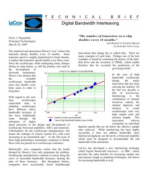
Digital Bandwidth Interleaving - Teledyne LeCroy
Digital Bandwidth Interleaving - Teledyne LeCroy
Digital Bandwidth Interleaving - Teledyne LeCroy

Create successful ePaper yourself
Turn your PDF publications into a flip-book with our unique Google optimized e-Paper software.
<strong>Digital</strong> <strong>Bandwidth</strong> <strong>Interleaving</strong><br />
Peter J. Pupalaikis<br />
Principal Technologist<br />
March 29, 2005<br />
The empirical and eponymous Moore’s Law 1 claims that<br />
transistor density doubles every 18 months. Since<br />
transistor speed is roughly proportional to linear density,<br />
it implies that transistor speeds double every three years.<br />
Since the oscilloscope, while undergoing many changes<br />
during its long history, is still the primary tool used in<br />
the development of<br />
electronic instruments,<br />
Moore’s law dictates that<br />
the<br />
available<br />
oscilloscope bandwidth<br />
must also double every<br />
three years in order to<br />
keep pace.<br />
With regard to the realtime<br />
oscilloscopes<br />
(equivalent time, or<br />
sampling oscilloscopes<br />
have different rules),<br />
bandwidth increases of<br />
late have traditionally<br />
come through the<br />
utilization of higher<br />
speed processes in the design and development of<br />
oscilloscope front-end amplifiers, ADCs and memories.<br />
Unfortunately for the oscilloscope manufacturers, this<br />
means the redesign of various custom ICs, with costs<br />
increasing at an exponential rate. 2 As the life-cycle of<br />
these high performance instruments continues to shrink,<br />
these costs are passed on to oscilloscope customers.<br />
Historically, wise companies realize that the trends<br />
dictated by Moore’s Law only perpetuate the problem.<br />
Oscilloscope manufacturers continue to march along the<br />
curve of inexorable bandwidth increases, bearing the<br />
pain of these increases. But throughout history,<br />
companies have occasionally found breakthrough<br />
"The number of transistors on a chip<br />
doubles every 18 months."<br />
- attributed to Gordon Moore<br />
Co-founder Intel Corp.<br />
innovations that change the so called rules. There are<br />
many examples of such feats. Perhaps one of the best<br />
examples is found by examining the history of the harddisk<br />
drive and the invention of PRML, which enable<br />
densities that far exceeded the predictions of the<br />
governing trends. 3<br />
In the area of high<br />
bandwidth oscilloscope<br />
design, the major<br />
innovation that has been<br />
carrying the industry for<br />
the last two decades is<br />
that of interleaving.<br />
<strong>Interleaving</strong> is the<br />
combination of channel<br />
resources, namely the<br />
channel digitizers and<br />
memory, to create<br />
oscilloscopes with very<br />
high sample rates and<br />
memory lengths. This<br />
innovation relieves<br />
constraints on individual<br />
digitizer speeds that are far below the effective sample<br />
rates achieved. While interleaving has been highly<br />
successful, it does not address bandwidth, since<br />
Interleaved digitizers are driven by a front-end amplifier<br />
which must be designed to accommodate the end<br />
bandwidth of the instrument.<br />
<strong>LeCroy</strong> has developed a new interleaving technique<br />
called <strong>Digital</strong> <strong>Bandwidth</strong> Interleave - or DBI - which<br />
provides the same benefits for increasing sample rate<br />
and memory length as traditional techniques, but allows<br />
for increasing bandwidth as well.
While traditional interleaving has<br />
certain hardware requirements of<br />
delivering signals and clocks to<br />
multiple paths, the problem is mainly<br />
calibration of the timing and<br />
gain/offset of the multiple paths.<br />
There are many ways to approach<br />
this calibration, and the algorithms<br />
for obtaining the best correction can<br />
be quite complex. However, the<br />
software which accomplishes the<br />
interleave is basically<br />
straightforward.<br />
<strong>Digital</strong> bandwidth interleave, on the<br />
other hand, involves additional<br />
hardware, calibration and digital<br />
signal processing at the back end to<br />
recover the signal input by the<br />
oscilloscope user.<br />
Input<br />
A simplified diagram of the hardware topology of DBI is<br />
shown. Basically, the input signal is split with a<br />
diplexer. A diplexer is a microwave filter designed to<br />
split incoming signals into multiple frequency bands. In<br />
the case of a two channel, bandwidth doubling<br />
arrangement, the low frequency band is delivered from<br />
the diplexer directly into one front<br />
end. The cutoff of the low<br />
frequency path from the diplexer<br />
has been designed to pass an entire<br />
frequency band which meets the<br />
bandwidth capabilities of the<br />
oscilloscope front-end. The high<br />
frequency band enters a<br />
downconverter. The downconverter<br />
is realized utilizing a wide-band<br />
mixer. The downconverter mixes a<br />
predetermined local oscillator with<br />
the incoming high frequency band<br />
and produces two image bands –<br />
one at the difference frequency and<br />
the other at the sum frequency. The<br />
difference frequency is an image of<br />
the high frequency band passed to<br />
the mixer, but is now within a band<br />
that can be handled by the<br />
oscilloscope front-end. Therefore<br />
the high frequency band has been<br />
shifted in its entirety to a lower<br />
frequency band. This uses the same<br />
basic concept as a radio receiver. In<br />
essence, both the low and high<br />
frequency bands are acquired by the<br />
Input<br />
Front-end<br />
Amplifier<br />
Digitizers<br />
Memory<br />
Traditional Interleave Topology<br />
Diplexer<br />
Downconvertor<br />
<strong>Bandwidth</strong> Interleave Topology<br />
oscilloscope, with the low band in its<br />
original location and the high band<br />
"moved" to a different (lower) frequency<br />
location.<br />
Once acquired, each band undergoes signal<br />
processing. The main effect of the<br />
processing is to remix the high frequency<br />
band with a digitally synthesized replica of<br />
the local oscillator to move the band into<br />
the correct frequency locations. It also<br />
digitally rejects the new image created by<br />
the mixing action. Finally, the two bands<br />
are recombined forming an acquisition that<br />
is almost double the bandwidth of an<br />
acquisition utilizing a single oscilloscope<br />
channel.<br />
A key point to remember about DBI is that<br />
each frequency band is within the<br />
bandwidth capability of the acquisition channel which<br />
will acquire it. The digital signal processing is used to<br />
recombine the waveforms, but is not being used to<br />
“extend” the bandwidth of a channel. Thus, the<br />
problems with bandwidth extension, such as increased<br />
noise, are not introduced in a DBI based oscilloscope.<br />
Front-end<br />
Amplifier<br />
Digitizers<br />
Memory<br />
DBI technology is enabled by<br />
two key elements: The first is<br />
the recent improvements in the<br />
performance of microwave and<br />
RF technologies. A new<br />
generation of wide bandwidth<br />
amplifiers, mixers, attenuators,<br />
filters, etc. can achieve the<br />
amplitude accuracies required<br />
for use in the input signal path<br />
of a real time oscilloscope.<br />
The second enabler is the speed<br />
of digital signal processing<br />
within Intel Pentium processor<br />
based instruments. While not<br />
generally thought of as a “signal<br />
processor”, the Pentium is the<br />
fastest floating point digital<br />
signal processor in the world 4 .<br />
With the available raw<br />
processing power, <strong>LeCroy</strong><br />
mastered the digital signal<br />
processing techniques for the<br />
compensation of analog signal<br />
paths. The final challenge was
devising and implementing the complex routines used in<br />
the automated test systems which calibrate the<br />
instrument. The result is a solution that operates with<br />
incredible performance.<br />
DBI is a technology that shifts the limitations on realtime<br />
oscilloscope bandwidth from cost, design effort and<br />
speed limitations of IC design processes available to<br />
limitations dictated by speeds of RF and microwave<br />
design technology. As applied today, DBI lifts the bar<br />
by at least a factor of three and will continue to increase<br />
in the future.<br />
As such, DBI is an innovation that provides a<br />
discontinuity or disruption in the oscilloscope bandwidth<br />
trend. In the future, <strong>LeCroy</strong> will introduce oscilloscopes<br />
with DBI built in at the beginning of the design cycle.<br />
Future realtime oscilloscopes will give the user the<br />
ability to eliminate bandwidth as a prime consideration<br />
when trying to determine which types of instruments<br />
will suit their measurement needs.<br />
The resulting DBI enabled oscilloscope performs the<br />
same as an instrument implemented with traditional<br />
technology. Parameters such as accuracy and noise are<br />
essentially the same. Frequency response accuracy and<br />
return loss, parameters of particular importance for<br />
accurately reproducing eye diagrams of serial data<br />
signals, have actually improved in the first instrument<br />
designed with DBI.<br />
The SDA 11000 – <strong>LeCroy</strong>’s first DBI enabled serial data<br />
analyzer operates at 11 GHz bandwidth and 40 GS/s<br />
sample-rate<br />
The author is Principal Technologist at <strong>LeCroy</strong> and a<br />
co-inventor of the <strong>Digital</strong> <strong>Bandwidth</strong> Interleave<br />
technology. He has held a variety of titles during his ten<br />
year career at <strong>LeCroy</strong> including digital signal<br />
processing engineer and product marketing manager for<br />
high performance oscilloscopes. He holds a BSEE from<br />
Rutgers University and is a member of Tau Beta Pi, Eta<br />
Kappa Nu and the IEEE communications and signal<br />
processing societies. He holds several patents in the<br />
area of the application of digital signal processing to<br />
measurement instruments.<br />
1 Gordon E. Moore, “Cramming more components onto<br />
integrated circuits”, Electronics, Volume 38, Number 8, April<br />
19, 1965<br />
2 Simon Young, “The Risk/Reward Realities of Chip<br />
Development”, TechOnLine Publication, Nov. 7, 2002<br />
3 Clayton M. Christensen, “The Innovator’s Dilemma”,<br />
Harvard Business School Press, 1997<br />
4 BDTImark2000 TM Scores, Berkeley Design Technology,<br />
Inc., June 2001<br />
Eye pattern from 6 Gb/s PRBS measured with SDA 11000<br />
1-800-5-<strong>LeCroy</strong><br />
www.lecroy.com