LAB 6 - Remote Control - Teledyne LeCroy
LAB 6 - Remote Control - Teledyne LeCroy
LAB 6 - Remote Control - Teledyne LeCroy

Create successful ePaper yourself
Turn your PDF publications into a flip-book with our unique Google optimized e-Paper software.
Lab 6 – EasyScope <strong>Remote</strong> <strong>Control</strong> (30 Minutes)<br />
Note:(Screenshots below show a white background configuration of your WaveAce to save black<br />
ink in printing, this configuration is explained in Lab 2 – VIEW)<br />
Overview<br />
Goal<br />
The EasyScope software utility includes with each WaveAce oscilloscope provides remote control<br />
of your oscilloscope. This exercise demonstrates the use of this tool.<br />
A test at the end of the Lab allows you to check your knowledge.<br />
Learn how to:<br />
- <strong>Remote</strong>ly save and recall waveform graphs<br />
- <strong>Remote</strong>ly save and recall waveform data<br />
- Perform pass/fail testing<br />
- <strong>Remote</strong>ly save a picture (screen shot)<br />
In this Lab you will learn how you can operate the scope using your PC.<br />
System Requirements - 1 x WaveAce passive probe.<br />
- A PC with a free USB<br />
- USB cable (included with WaveAce oscilloscope).<br />
Setup<br />
Connect the probe to Channel 2 and the probe top to the calibrator (CAL) output loop on the front<br />
panel. Use the sprung hook accessory of the probe to clip to the CAL output loop.<br />
Connect the oscilloscope scope to your PC but do not turn it on at this stage.<br />
If EasyScope and USB driver are already installed proceed to step 9, if not start at step 1.<br />
Step 1<br />
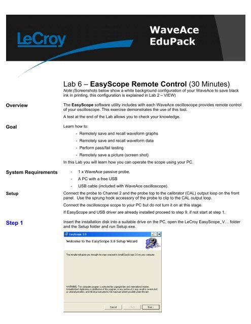
Insert the installation disk into a suitable drive on the PC, open the <strong>LeCroy</strong> EasyScope_V… folder<br />
and the Setup folder and run Setup.exe.
Click Next >.<br />
Step 2<br />
Click Next >.<br />
Step 3<br />
Click Next > and the installation will proceed.
Step 4<br />
After installation has completed click Close.<br />
Step 5 If only the the USB driver is already installed proceed to step 9.<br />
Step 6<br />
Turn on the oscilloscope and connect it to your PC using the USB serial cable. Microsoft Windows<br />
automatically detects the oscilloscope and displays the Found New Hardware Wizard. Select Install<br />
from a list or specific location (Advanced).<br />
Click Next >.<br />
Step 7<br />
Choose Include this location in the search and click Browse to locate the USB Driver folder and<br />
then click Next. The USB Driver will be installed.
Click Next >.<br />
Step 8<br />
With some versions of Windows you may see a warning message at this point. If so click on<br />
Continue Anyway. When installation has completed click Finish to exit. Turn off the oscilloscope.<br />
Step 9<br />
For convenience the installer places an icon on the Windows desktop.<br />
Run the EasyScope application either directly or by double clicking this icon. Two red circles<br />
will be displayed in the top right corner of the application window. Turn on the scope and the left<br />
circle will change to green. Click the Connect icon at the top left and the two green circles<br />
are displayed.
Step 10<br />
Reset the scope configuration to the default factory settings using the front panel DEFAULT<br />
SETUP button. An alternative method is to use the front panel SAVE/RECALL button, then press<br />
the Type button until Factory is displayed and finally press the Load button.<br />
At any time the menu on the right-hand side of the screen can be removed/restored by pressing the<br />
front panel MENU ON/OFF button.<br />
Step 11<br />
Turn CH1 off and CH2 on by pressing the front panel CH1 and CH2 buttons. Pressing a channel<br />
button also displays the corresponding vertical settings. DC coupling on CH2 is selected by default.<br />
Check the slider switch on the probe is set to X10 and using the Probe button set 10X on the<br />
screen.<br />
Step 12<br />
Press the [blue] AUTO button on the front panel. In a few seconds you should have a triggered<br />
signal with a number of cycles shown on the screen.
Step 13<br />
Notes: As an alternative to<br />
manually refreshing the graph<br />
using the Refresh button the<br />
Mode can be set to Auto. In this<br />
mode the graph is updated<br />
automatically every few<br />
seconds.<br />
In the Goto View section of the EasyScope screen click on Wave Graph and then click on<br />
Refresh in the Graph windows. A graph of the waveforms is displayed and the current<br />
settings are shown below.<br />
Waveforms can be saved in<br />
either binary (*.wdf) or ASCII<br />
(*.csv). Binary files are more<br />
compact but ASCII files are<br />
more convenient when used<br />
with an external application<br />
such as Excel etc.<br />
Click on Save and on the pop-up screen choose the channel (CH1) and clock OK. The<br />
next screen allows you to select the destination and save format. Set type as graph file<br />
(*.csv), name it Lab6.csv and click Save.
Step 14<br />
In the Graph Show box click on CH1 to turn off the CH1 graph. Now in Graph Oper click<br />
on Open and select the Lab6.csv file. The previously saved data is displayed as Chan3.<br />
Step 15<br />
Note: Data can also be printed<br />
by clicking on the Print button.<br />
A preview screen is first shown<br />
In Goto View click on Wave Data. The current data is listed.
and clicking on the printer icon<br />
will print to the default printer.<br />
Click on Save as and select CH1 and OK. The type is now always wavedata file (*.wdf).<br />
Name the file Lab6.wdf and click Save.<br />
Step 16<br />
Select the Wave Graph view again and in Graph Show turn on CH1 and turn off Chan3. In the<br />
Measure section select CH1 and click Auto so the waveform is continually refreshed.
Now select the Wave Measure view and CH1 is compared to a set of Pass/Fail settings.<br />
To change a setting click on Pass|Fail, select a measurement and set Enable to allow the limits to<br />
be changed.
Measurement data can also be saved used the Save As button and is saved as a (*.wmf) file. The<br />
Measure file button in the Open Files box can be used to recall these measurements.<br />
Step 17<br />
In Goto View click on DSO Bitmap. Click on the Refresh button and the current scope<br />
screen is displayed.<br />
As for the other Views this view can be saved to disk (and recalled) by using the Save and<br />
Open buttons.
Step 18<br />
As an exercise click on the Panel icon on the toolbar. See if you can use this to change<br />
the scope settings.
Test<br />
Question 1<br />
How would you load a channel’s waveform data into Excel?<br />
………………………………………………………………<br />
………………………………………………………………<br />
………………………………………………………………<br />
………………………………………………………………<br />
Question 2<br />
Is it possible to save and recall instrument Setups to and from the PC?<br />
………………………………………………………………<br />
………………………………………………………………<br />
………………………………………………………………<br />
………………………………………………………………<br />
Question 3<br />
On the Wave Graph view there is a checkbox called GetAllData. Check this and click on the<br />
Refresh button. More cycles are now shown on the graph. Why is this?<br />
………………………………………………………………<br />
………………………………………………………………<br />
………………………………………………………………<br />
………………………………………………………………<br />
Summary<br />
In this lab you have learned to control the WaveAce using the EasyScope application and to save<br />
and recall information.