SUBJECT: Pipe Installation Specifications APPLICABILITY: Groton ...
SUBJECT: Pipe Installation Specifications APPLICABILITY: Groton ...
SUBJECT: Pipe Installation Specifications APPLICABILITY: Groton ...

You also want an ePaper? Increase the reach of your titles
YUMPU automatically turns print PDFs into web optimized ePapers that Google loves.
SECTION 15010<br />
June 16, 2005<br />
GENERAL REQUIREMENTS, MECHANICAL<br />
A. GENERAL<br />
1. All piping entering the Shipyard must be controlled per Shipyard Standard Procedure # 21.1-1.<br />
2. All piping shall be in accordance with Facilities Department instruction # 508-006.<br />
GENERAL DYNAMICS<br />
Electric Boat<br />
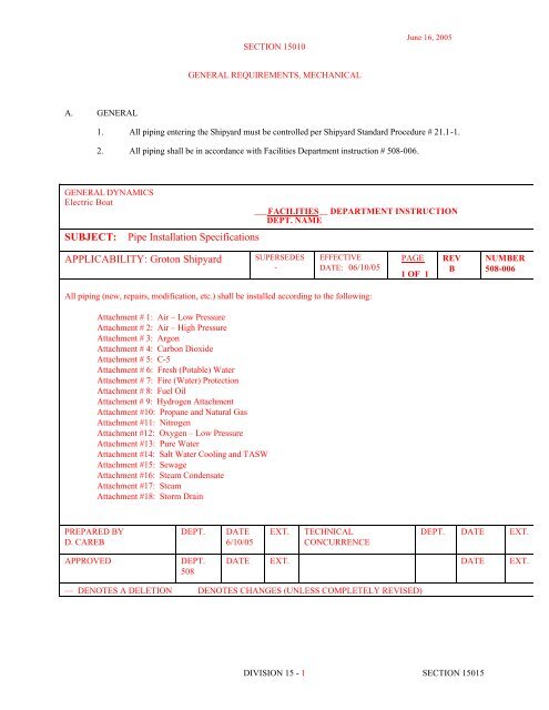
<strong>SUBJECT</strong>:<br />
<strong>Pipe</strong> <strong>Installation</strong> <strong>Specifications</strong><br />
___FACILITIES__ DEPARTMENT INSTRUCTION<br />
DEPT. NAME<br />
<strong>APPLICABILITY</strong>: <strong>Groton</strong> Shipyard<br />
SUPERSEDES<br />
-<br />
EFFECTIVE<br />
DATE: 06/10/05<br />
PAGE<br />
1 OF 1<br />
REV<br />
B<br />
NUMBER<br />
508-006<br />
All piping (new, repairs, modification, etc.) shall be installed according to the following:<br />
Attachment # 1: Air – Low Pressure<br />
Attachment # 2: Air – High Pressure<br />
Attachment # 3: Argon<br />
Attachment # 4: Carbon Dioxide<br />
Attachment # 5: C-5<br />
Attachment # 6: Fresh (Potable) Water<br />
Attachment # 7: Fire (Water) Protection<br />
Attachment # 8: Fuel Oil<br />
Attachment # 9: Hydrogen Attachment<br />
Attachment #10: Propane and Natural Gas<br />
Attachment #11: Nitrogen<br />
Attachment #12: Oxygen – Low Pressure<br />
Attachment #13: Pure Water<br />
Attachment #14: Salt Water Cooling and TASW<br />
Attachment #15: Sewage<br />
Attachment #16: Steam Condensate<br />
Attachment #17: Steam<br />
Attachment #18: Storm Drain<br />
PREPARED BY<br />
D. CAREB<br />
DEPT.<br />
DATE<br />
6/10/05<br />
EXT.<br />
TECHNICAL<br />
CONCURRENCE<br />
DEPT. DATE EXT.<br />
APPROVED<br />
DEPT.<br />
508<br />
DATE EXT. DATE EXT.<br />
— DENOTES A DELETION DENOTES CHANGES (UNLESS COMPLETELY REVISED)<br />
DIVISION 15 - 1 SECTION 15015
June 16, 2005<br />
16 May 2005<br />
Department Instruction 508-006: <strong>Pipe</strong> <strong>Installation</strong> <strong>Specifications</strong><br />
Attachment #1: Air-Low Pressure<br />
Scope: This specification is for the design, installation, test and repair of the shipyard air-low pressure system piping,<br />
including the compressor facility system and the air distribution system to the service connection on the piping system.<br />
In general, the air-low pressure system piping shall conform to the requirements of ASME B31.3 except as specifically<br />
identified by contract or work order. Specification sections refer to the latest version of the Facilities Material<br />
<strong>Specifications</strong>.<br />
Design:<br />
Nominal Operating Pressure/Temperature: 100 psi. Temperature: Ambient<br />
Design Pressure/Temperature: 100 psi. Temperature: Ambient<br />
Materials:<br />
<strong>Pipe</strong> and Fittings:<br />
Above Ground<br />
2” and smaller – Section 15061; Type S-1 (Sch 40, ASTM A53 Stl, 150#, Screwed or welded)<br />
Type S-4 (Sch 40, ASTM A53 Stl, 125#, Flanged or welded)<br />
2½” and larger – Section 15061; Type S-4 (Sch 40, ASTM A53 Stl, 125#, Flanged or welded)<br />
Below Ground<br />
All sizes – Section 15070; Special Underground Piping System, Type S-4<br />
Testing:<br />
Valves:<br />
2” and smaller – Section 15101; Type GT-1 (Gate, 125#, Screwed or welded) or Section<br />
15103; Type B-2 (Ball, 600# 3-Piece, Full Port)<br />
2½” and larger – Section 15101; Type GT-4 (Gate, 125#, Flanged or welded) or Section 15104;<br />
Type BF- 2 (Butterfly, 200#, Lugged)<br />
Service Manifold Valves – 3/4” Port Offset Air Valve Assembly, bronze body and Plug, self-venting,<br />
Manufacturer: Bowes P/N 52026.<br />
Hydrostatic pressure test with water to 150 psi per ANSI B31.3. Minimum test duration shall be 10 minutes or<br />
until all joints are inspected there shall be no pressure drop or evidence of leakage. Drain and blow down lines<br />
following test.<br />
System Cleanliness:<br />
Piping shall be wiped free, inside and outside of all oil, grease, metal cuttings, and debris during fabrication.<br />
Following test, all equipment, piping, valves, and strainers shall be cleaned inside and outside of oil,<br />
grease, metal cuttings, and sludge that may have accumulated during tests and dried. All surplus<br />
materials and debris shall be removed as directed.<br />
Labeling:<br />
Section 15190: Piping shall be labeled per the requirements of ASME A13.1. Labels shall read “Air – Low Pressure –<br />
100 psi” and have yellow background with black lettering.<br />
DIVISION 15 - 2 SECTION 15015
16 May 2005<br />
Department Instruction 508-006: <strong>Pipe</strong> <strong>Installation</strong> <strong>Specifications</strong><br />
June 16, 2005<br />
Attachment #2: Air – High Pressure<br />
Scope: This specification is for the design, installation, test and repair of the shipyard high pressure air (HP Air)<br />
distribution system piping from the pressure reducing stations at the compressor station to the service connections on the<br />
piping system. The HP Air system piping shall conform to the requirements of ASME B31.3 for High Pressure Service<br />
except as specifically identified by contract or work order. Specification sections refer to the latest version of the<br />
Facilities Material <strong>Specifications</strong>.<br />
Design:<br />
Normal Operating Pressure/Temperature: 4,500 psi. Temperature: Ambient<br />
Design Pressure/Temperature: 5,000 psi. Temperature: 150°F<br />
Materials: Note Pre-Cleaning Requirements of SSP 1.9<br />
<strong>Pipe</strong>: Section 15068; Type SS-4 (Sch. 160S, ASTM 312, Grade TP304, Stainless Steel)<br />
Fittings: Class 6000, socket weld, 304 Stainless Steel<br />
Unions: Class 6000, socket weld, 304 Stainless Steel, CPV O-Seal Model 51, Buna-N O-rings, Monel union<br />
nut.<br />
Valves: All valves shall be purchased commercially as Oxygen clean:<br />
Class 6000, CPV O-Seal Shut-off Valve Model 380, 304 Stainless Steel, Buna-N O-rings,<br />
Polyurethane stem seal, and Teflon backup ring.<br />
Testing:<br />
Class 6000, CPV Model 157 Relief Valve, Stainless Steel with Monel nuts.<br />
Pneumatic pressure test to 7,500 psi with air per ANSI B31.3. (Note: Specific procedures and precautions for<br />
pneumatic testing found in ANSI B31.3 must be followed.) Minimum test duration shall be 10 minutes then<br />
reduce pressure to 5,000 psi and examine for leakage by soap bubble or equivalent method.<br />
- OR –<br />
Hydrostatic pressure test with Grade “B” water to 7,500 psi per ANSI B31.3. Minimum test duration shall be<br />
10 minutes then reduce pressure to 5,000 psi and examine for leakage. Except for possible localized instances<br />
at pump or valve packing, there shall be no evidence of leakage. Drain and blow down lines following test.<br />
Lines must be purged and dried to a -60°F dew point before being put into service.<br />
System Cleanliness:<br />
Prior to fabrication, all piping, valves, assemblies, and components shall be cleaned per SSP 1.9 Attachment 1 (which<br />
meets the requirements of MIL-STD-1622).<br />
The system cleanliness boundary for connection to the HPA system shall be established at the service connections by<br />
installation of the required filtration equipment. The system cleanliness boundary for connection to<br />
systems required to meet MIL-STD-1330 shall be established at the filtration equipment.<br />
Labeling:<br />
Section 15190: Piping shall be labeled per the requirements of ASME B13.3. Labels shall read “Air – High<br />
Pressure – 4500 psi” and have yellow background with black lettering.<br />
DIVISION 15 - 3 SECTION 15015
16 May 2005<br />
.Department Instruction 508-006: <strong>Pipe</strong> <strong>Installation</strong> <strong>Specifications</strong><br />
June 16, 2005<br />
Attachment #3: Argon<br />
Scope: This specification is for the design, installation, test and repair of the shipyard argon system piping from the<br />
pressure/temperature control module at the argon storage tank to the service connection on the piping system. The<br />
argon system piping shall conform to the requirements of ASME B31.3 except as specifically identified by contract or<br />
work order. Specification sections refer to the latest version of the Facilities Material <strong>Specifications</strong>.<br />
Design:<br />
Normal Operating Pressure/Temperature: 135 psi. Temperature: Ambient<br />
Design Pressure/Temperature: 150 psi. Temperature: Ambient<br />
Materials:<br />
<strong>Pipe</strong> and Fittings:<br />
Above Ground<br />
Section 15062, Type C-3 (K – Copper, ASTM B88, Brazed), Type B-1 (Red Brass, ASTM B43, Sch<br />
40, Brazed) or Type C-5 (Copper, ASTM B42, Sch 40, Brazed)<br />
Below Ground<br />
Section 15062, Type B-1 (Sch 40 Red Brass, ASTM B43, Brazed) or Type C-5 (Sch 40 Copper,<br />
ASTM B42, Brazed)<br />
Valves: All valves shall be purchased commercially Oxygen clean:<br />
Line Valves –<br />
Manufacturer: Rego 2500 series diaphragm, bronze body.<br />
Service Manifold Valves –<br />
Manufacturer: Rego 7160 series.<br />
Testing:<br />
Pneumatic pressure test with nitrogen to 225 psi per ANSI B31.3. (Note: Specific procedures and precautions<br />
for pneumatic testing found in ANSI B31.3 must be followed.) All joints are to be tested using a soap bubble<br />
method. Once all leaks are repaired and the bubble test indicates no leaks, a 24-hour drop test at 225 psi shall<br />
be preformed on the system.<br />
System Cleanliness:<br />
Prior to fabrication, all piping, valves, assemblies, and components shall be cleaned SSP 1.9 Attachment 1 (which<br />
meets the requirements of MIL-STD-1622). Note that these cleanliness requirements are similar for<br />
HPA. During fabrication, piping shall be maintained under nitrogen pressure or purge at all times.<br />
Following the final test the system shall be evacuated to 25 inches mercury vacuum then break the vacuum with<br />
argon. Lab Services, Dept. 341, shall test argon purity from system. Repeat this process until Dept 341<br />
validates argon purity.<br />
Labeling:<br />
Section 15190: Piping shall be labeled per the requirements of ASME A13.1. Labels shall read “Argon” and have<br />
blue background with white lettering.<br />
DIVISION 15 - 4 SECTION 15015
16 May 2005<br />
Department Instruction 508-006: <strong>Pipe</strong> <strong>Installation</strong> <strong>Specifications</strong><br />
June 16, 2005<br />
Attachment #4: Carbon Dioxide<br />
Scope: This specification is for the design, installation, test and repair of the shipyard Carbon Dioxide system. In general,<br />
the Carbon Dioxide system piping shall conform to the requirements of ASME B31.3 except as specifically identified by<br />
contract or work order. Specification sections refer to the latest version of the Facilities Material <strong>Specifications</strong>.<br />
Design:<br />
Nominal Operating Pressure/Temperature: 135 psi. Temperature: Ambient<br />
Design Pressure/Temperature: 150 psi. Temperature: Ambient<br />
Materials:<br />
<strong>Pipe</strong> and Fittings:<br />
Above Ground<br />
Section 15062, Type C-3 (K – Copper, ASTM B88, Brazed), Type B-1 (Red Brass, ASTM B43, Sch<br />
40, Brazed) or Type C-5 (Copper, ASTM B42, Sch 40, Brazed)<br />
Below Ground<br />
Section 15062, Type B-1 (Sch 40 Red Brass, ASTM B43, Brazed) or Type C-5 (Sch 40 Copper,<br />
ASTM B42, Brazed)<br />
Valves: Line Valves –<br />
Manufacturer: Rego 2500 series.<br />
Service Manifold Valves –<br />
Manufacturer: Rego 7160 series.<br />
Testing:<br />
Hydrostatic pressure test with water to 225 psi per ANSI B31.3. Minimum test duration shall be 10 minutes or<br />
until all joints are inspected there shall be no pressure drop or evidence of leakage. Drain and blow down lines<br />
following test.<br />
System Cleanliness:<br />
Prior to fabrication, all piping, valves, assemblies, and components shall be cleaned SSP 1.9 Attachment 1 (which<br />
meets the requirements of MIL-STD-1622). Note that these cleanliness requirements are similar for<br />
HPA. During fabrication, piping shall be maintained under nitrogen pressure or purge at all times.<br />
Following the final test the system shall be evacuated to 25 inches mercury vacuum then break the vacuum with CO2<br />
gas. Lab Services, Dept. 341, shall test CO2 gas purity from system. Repeat this process until Dept<br />
341 validates CO2 gas purity.<br />
Labeling:<br />
Section 15190: Piping shall be labeled per the requirements of ASME A13.1. Labels should read “Carbon Dioxide –<br />
CO 2 ” and shall have yellow background with black lettering.<br />
DIVISION 15 - 5 SECTION 15015
16 May 2005<br />
Department Instruction 508-006: <strong>Pipe</strong> <strong>Installation</strong> <strong>Specifications</strong><br />
June 16, 2005<br />
Attachment #5: C-5 Mixed Gas (95% Argon with 5% Carbon Dioxide)<br />
Scope: This specification is for the design, installation, test and repair of the shipyard C-5 system piping from the gas<br />
mixing stations to the service connection on the piping system. The C-5 system piping shall conform to the<br />
requirements of ASME B31.3 except as specifically identified by contract or work order. Specification sections refer to<br />
the latest version of the Facilities Material <strong>Specifications</strong>.<br />
Design:<br />
Normal Operating Pressure/Temperature: 65 psi. Temperature: Ambient<br />
Design Pressure/Temperature: 100 psi. Temperature: Ambient<br />
Materials:<br />
<strong>Pipe</strong> and Fittings:<br />
Above Ground<br />
Section 15062, Type C-3 (K – Copper, ASTM B88, Brazed), Type B-1 (Red Brass, ASTM B43, Sch<br />
40, Brazed) or Type C-5 (Copper, ASTM B42, Sch 40, Brazed)<br />
Below Ground<br />
Section 15062, Type B-1 (Sch 40 Red Brass, ASTM B43, Brazed) or Type C-5 (Sch 40 Copper,<br />
ASTM B42, Brazed)<br />
Valves: Line Valves –<br />
Manufacturer: Rego 2500 series.<br />
Service Manifold Valves –<br />
Manufacturer: Rego 7160 series.<br />
Testing:<br />
Pneumatic pressure test with nitrogen to 150 psi per ANSI B31.3. (Note: Specific procedures and precautions<br />
for pneumatic testing found in ANSI B31.1 must be followed.) All joints are to be tested using a soap bubble<br />
method. Once all leaks are repaired and the bubble test indicates no leaks, a 24-hour drop test at 225 psi shall<br />
be preformed on the system.<br />
System Cleanliness:<br />
Prior to fabrication, all piping, valves, assemblies, and components shall be cleaned SSP 1.9 Attachment 1 (which<br />
meets the requirements of MIL-STD-1622). Note that these cleanliness requirements are similar for<br />
HPA. During fabrication, piping shall be maintained under nitrogen pressure or purge at all times.<br />
Following the final test the system shall be evacuated to 25 inches mercury vacuum then break the vacuum with C-5<br />
gas. Lab Services, Dept. 341, shall test C-5 gas purity from system. Repeat this process until Dept 341<br />
validates C-5 gas purity.<br />
Labeling:<br />
Section 15190: Piping shall be labeled per the requirements of ASME A13.1. Labels shall read “C-5 Gas” and have<br />
blue background with white lettering.<br />
DIVISION 15 - 6 SECTION 15015
16 May 2005<br />
Department Instruction 508-006: <strong>Pipe</strong> <strong>Installation</strong> <strong>Specifications</strong><br />
June 16, 2005<br />
Attachment #6: Fresh (Potable) Water<br />
Scope: This specification is for the design, installation, test and repair of the shipyard fresh (potable) water. In general,<br />
the fresh (potable) water system piping shall conform to the requirements of American Water Works Association<br />
(AWWA) and appropriate Building Codes except as specifically identified by contract or work order. Specification<br />
sections refer to the latest version of the Facilities Material <strong>Specifications</strong>.<br />
Design:<br />
Materials:<br />
Nominal Operating Pressure/Temperature: 100 psi. Temperature: Ambient<br />
Design Pressure/Temperature: 125 psi. Temperature: Ambient<br />
<strong>Pipe</strong> and Fittings:<br />
<strong>Pipe</strong> and fittings (2 inches and smaller) above grade shall be copper, Specification Section 15062,<br />
System Type C-1.<br />
<strong>Pipe</strong> and fittings (2-1/2 inches and larger) above grade shall be copper, Specification Section 15062,<br />
System Type C-2.<br />
**OR**<br />
Valves:<br />
<strong>Pipe</strong> and fittings (2-1/2 inches and larger) above grade shall be steel, Specification Section 15061,<br />
System Type S-9.<br />
<strong>Pipe</strong> and fittings (2 inches and smaller) below grade shall be copper, Specification Section 15062,<br />
System Type C-3.<br />
<strong>Pipe</strong> and fittings (2-1/2 inches and larger) below grade shall be ductile iron, Specification Section<br />
15064, System Type DI-1 or DI-2, at the Contractor's option.<br />
Isolation valves at equipment (2 inches and smaller) shall be ball valves, Specification Section 15103,<br />
Valve Type B-1.<br />
Isolation valves at equipment (2-1/2 inches and larger) shall be gate valves, Specification Section<br />
15101, Valve Type GT-4.<br />
Isolation valves in piping runs (2 inches and smaller) except at building entrance shall be ball valves,<br />
Specification Section 15103, Valve Type B-2.<br />
Isolation valves in piping runs (2-1/2 inches and larger), except at building entrance, shall be gate<br />
valves, Specification Section 15101, Valve Type GT-4.<br />
Check valves at pump discharges (2 inches and smaller) shall be per Specification Section 15106,<br />
Valve Type C-3.<br />
Check valves at pump discharges (2-1/2 inches and larger) shall be per Specification Section 15106,<br />
Valve Type C-6.<br />
Check valves for general use (2 inches and smaller) shall be per Specification Section 15106, Valve<br />
Type C-1.<br />
Check valves for general use (2-1/2 inches and larger) shall be per Specification Section 15106,<br />
Valve Type C-3.<br />
Drain valves shall be boiler drains per Specification Section 15110, Valve Type SD-1.<br />
Strainer blow-down valves shall be ball valves, Specification Section 15103, Valve Type B-1.<br />
Attachment #6: Fresh (Potable) Water, cont.<br />
Testing:<br />
Department Instruction 508-006: <strong>Pipe</strong> <strong>Installation</strong> <strong>Specifications</strong><br />
DIVISION 15 - 7 SECTION 15015
June 16, 2005<br />
Hydrostatic pressure test with water to 188 psi. Minimum test duration shall be 10 minutes or until all joints<br />
are inspected there shall be no pressure drop or evidence of leakage. Drain and blow down lines following test.<br />
System Cleanliness:<br />
Piping shall be wiped free, inside and outside of all oil, grease, metal cuttings, and debris during fabrication.<br />
All water lines shall be disinfected using the following procedure. Preliminary flushing shall be done prior to<br />
chlorination as thoroughly as possible with water pressure and outlets available.<br />
Sterilization<br />
a) Before being placed in service, all new mains, branches, and lines shall be chlorinated by<br />
introducing a solution containing not less than 50 parts per million of chlorine.<br />
b) The chlorine-bearing compounds to be used shall be calcium hypochlorite, chlorinated lime or<br />
sodium hypochlorite.<br />
c) In the process of chlorinating the system, all valves or appurtenances shall be operated while the<br />
lines are being filled with the chlorinating agent.<br />
d) With the required chlorine solution present, the system shall be secured for a period of not less<br />
than 24 hours. After retention period, tests shall be made to determine a chlorine residual of not less<br />
than 10 ppm.<br />
Final Flushing and Test<br />
Following chlorination, all treated water shall be flushed from the system at its extremities until the<br />
replacement water throughout the system shall be proved comparable in quality to the water<br />
from the water supply system and approved by the Owner.<br />
Labeling:<br />
Section 15190: Piping shall be labeled per the requirements of ASME A13.1. Labels shall read “Potable Water” have<br />
green background with white lettering.<br />
.<br />
DIVISION 15 - 8 SECTION 15015
16 May 2005<br />
June 16, 2005<br />
Department Instruction 508-006: <strong>Pipe</strong> <strong>Installation</strong> <strong>Specifications</strong><br />
Attachment #7:<br />
Fire (Water) Protection<br />
Scope: This specification is for the installation, test, repair and flushing of buried fire protection mains including<br />
piping, isolation valves, thrust blocks, and hydrants.<br />
Design:<br />
Nominal Operating Pressure/Temperature: 125psi Temperature: Ambient<br />
Design Pressure/Temperature: 125psi Temperature: Ambient<br />
Materials:<br />
See “Facilities Specification Manual” dated 7 January 2004, Sections 15061 through 15063 and 15310.<br />
WET-PIPE SPRINKLER SYSTEM PIPE AND FITTINGS<br />
<strong>Pipe</strong> and fittings (2 inches and smaller) above grade, shall be steel, System Type S-8.<br />
<strong>Pipe</strong> and fittings (2-1/2 inches and larger) above grade, shall be steel, System Type S-10.<br />
<strong>Pipe</strong> and fittings, below grade, shall be ductile iron, System Type DI-2.<br />
DRY-PIPE SYSTEM PIPE AND FITTINGS<br />
<strong>Pipe</strong> and fittings (2 inches and smaller) shall be steel, System Type S-8.<br />
<strong>Pipe</strong> and fittings (2-1/2 inches and larger) shall be steel, System Type S-10.<br />
SPRINKLER SYSTEM VALVES<br />
Isolation valves (2 inches and smaller) shall be gate valves, Valve Type GT-3.<br />
Isolation valves (2-1/2 inches and larger) shall be gate valves, Valve Type GT-6.<br />
Trim valves at alarm valves shall be ball valves, Valve Type B-1.<br />
Check valves (2-1/2 inches and larger) shall be Valve Type C-7.<br />
Wet pipe and dry pipe alarm valves shall be as specified in Section 15322, SPRINKLER SYSTEM ALARM<br />
VALVES.<br />
<strong>Installation</strong>:<br />
See National Fire Protection Association Standard 24, “Standard for the <strong>Installation</strong> of Private Fire Service<br />
Mains and Their Appurtenances,” latest edition.<br />
See National Fire Protection Association “Fire Protection Handbook” Section “Suppression, Water Based<br />
Distribution Systems,” latest edition.<br />
Testing:<br />
Testing for both buried and exposed fire mains shall be the same: Hydrostatic pressure test with water to 200<br />
psi for two (2) hours. There shall be no pressure drop or evidence of leakage. Testing shall be witnessed by the<br />
Authority Having Jurisdiction and EB Facilities.<br />
System Cleanliness:<br />
All new or modified existing piping systems shall be flushed at a required flow to produce a minimum velocity<br />
of 10 feet per second (3 m/s) in the pipes, until all potential debris has been removed. Wet systems shall be left<br />
in the wet condition: dry systems shall be completely drained and air blown dry.<br />
Labeling:<br />
Section 15190: Piping shall be labeled per the requirements of ASME A13.1. Labels shall read “Fire Protection” and<br />
have red background with white lettering.<br />
DIVISION 15 - 9 SECTION 15015
16 May 2005<br />
Department Instruction 508-006: <strong>Pipe</strong> <strong>Installation</strong> <strong>Specifications</strong><br />
June 16, 2005<br />
Attachment #8: Fuel Oil<br />
Scope: This specification is for the design, installation, test and repair of the shipyard Fuel Oil system piping including<br />
#4 Fuel Oil and Diesel Fuel Oil. In general, the Fuel Oil system piping shall conform to the requirements of ASME<br />
B31.2 except as specifically identified by contract or work order. Specification sections refer to the latest version of the<br />
Facilities Material <strong>Specifications</strong>.<br />
Design:<br />
Nominal Operating Pressure/Temperature: 100 psi. Temperature: 80•F<br />
Design Pressure/Temperature: 150 psi. Temperature: 100•F<br />
Materials:<br />
<strong>Pipe</strong>:<br />
2” and smaller – Section 15061; Type S-1 (Sch 40, ASTM A53, Grade B Stl, 150#, plain ends)<br />
2½” and larger – Section 15061; Type S-4 (Sch 40, ASTM A53, Grade B Stl, 125#, beveled ends)<br />
Fittings:<br />
2” and smaller – 3000# forged steel socket weld to ASTM A105 (non-heat treated)<br />
Testing:<br />
2½” and larger – Standard weight seamless steel buttweld end to A234, Grade WPB<br />
Unions:<br />
3000# forged steel socket weld to A105 (non-heat treated) integral seats<br />
Flanges:<br />
2½” and larger – 150# forged steel weld neck with standard bore or slip-on to A181, Grade I,<br />
ANSI B16.5 raised face.<br />
Valves:<br />
2” and smaller – Ball: Steel socket weld, 800# 3 piece steel body, 11-13% chrome ball and<br />
stem, bolted body, Teflon seats, with lever, Pacific Model 326-CS-<br />
P5FS or approved equal.<br />
Gate: Steel socket-weld, 800# steel body, 11-13% chrome trim with stellite seat rings,<br />
OS&Y, bolted bonnet, solid disc, standard packing, Pacific Model<br />
596-2 or approved equal.<br />
Globe: Steel socket-weld, 800# steel body, 11-13% chrome trim with stellite integral seats,<br />
OS&Y, bolted bonnet, manufacturer’s standard packing, Pacific<br />
Model 7662-2 or approved equal.<br />
Check:<br />
Steel socket-weld, 800# steel body, 11-13% chrome trim with stellite<br />
integral seats, piston type, bolted cap, Pacific Model 3682-2 or<br />
approved equal.<br />
2½” and larger - Gate: Cast Steel flanged, 150# steel body, 11-13% chrome trim, OS&Y,<br />
bolted bonnet, solid or flexible disc, manufacture’s standard<br />
packing, Crane Model 47X or approved equal.<br />
Globe: Cast Steel flanged, 150# steel body, 11-13% chrome trim, OS&Y, bolted bonnet,<br />
plug type disc, manufacturer’s standard packing, Pacific Model<br />
160-1 or approved equal.<br />
Check:<br />
Cast Steel flanged, 150# steel body, 11-13% chrome trim, swing type bolted<br />
bonnet, Pacific Model 180-1 or approved equal.<br />
Hydrostatic pressure test with water to 225 psi per ANSI B31.2. Minimum test duration shall be 10 minutes or<br />
until all joints are inspected there shall be no pressure drop or evidence of leakage. Drain and blow down lines<br />
following test.<br />
16 May 2005<br />
DIVISION 15 - 10 SECTION 15015
Attachment #8: Fuel Oil, cont.<br />
June 16, 2005<br />
Department Instruction 508-006: <strong>Pipe</strong> <strong>Installation</strong> <strong>Specifications</strong><br />
System Cleanliness:<br />
Piping shall be wiped free, inside and outside of all oil, grease, metal cuttings, and debris during fabrication.<br />
Following test, all equipment, piping, valves, and strainers shall be cleaned inside and outside of oil,<br />
grease, metal cuttings, and sludge that may have accumulated during tests and dried. All surplus<br />
materials and debris shall be removed as directed.<br />
Labeling:<br />
Section 15190: Piping shall be labeled per the requirements of ASME A13.1. Labels shall read “Fuel Oil” and have<br />
yellow background with black lettering.<br />
DIVISION 15 - 11 SECTION 15015
25 March 2004<br />
Department Instruction 508-006: <strong>Pipe</strong> <strong>Installation</strong> <strong>Specifications</strong><br />
June 16, 2005<br />
Attachment #9: Hydrogen<br />
Scope: This specification is for the design, installation, test and repair of the shipyard Hydrogen Gas system piping from<br />
the hydrogen storage tanks to the service connection on the piping system. The Hydrogen Gas Distribution system<br />
piping shall conform to the requirements of ASME B31.3, Process Piping, and NFPA 50A, Standard for Gaseous<br />
Hydrogen Systems at Consumer Sites. Specification sections refer to the latest version of the Facilities Material<br />
<strong>Specifications</strong>.<br />
Design:<br />
Normal Operating Pressure/Temperature: 15 psi.Temperature: Ambient<br />
Design Pressure/Temperature: 50 psi. Temperature: Ambient<br />
Materials:<br />
<strong>Pipe</strong>: Section 15061; Type S-12 (Sch 40, ASTM A53 Stl, Socket Welded)<br />
Valves:<br />
Line Valves – Section 15102, Type GL-2 (300 PSIG, Screwed)<br />
Service Manifold Valves – Manufacturer: ½” AIRCO #801-0468 (left hand threads) w/cap and chain, or<br />
approved equal.<br />
Testing:<br />
Hydrostatic pressure test with water to 75 psi per ANSI B31.3. Minimum test duration shall be 60 minutes or<br />
until all joints are inspected there shall be no pressure drop or evidence of leakage. Drain and blow down lines<br />
with nitrogen following test.<br />
System Cleanliness:<br />
Piping shall be wiped free, inside and outside of all oil, grease, metal cuttings, and debris during fabrication.<br />
Following test, all equipment, piping, valves, and strainers shall be cleaned inside and outside of oil,<br />
grease, metal cuttings, and sludge that may have accumulated during tests and dried. All surplus<br />
materials and debris shall be removed as directed.<br />
Labeling:<br />
Section 15190: Piping shall be labeled per the requirements of ASME B13.1. Labels shall read “Hydrogen<br />
Gas” and have yellow background with black lettering.<br />
DIVISION 15 - 12 SECTION 15015
June 16, 2005<br />
25 March 2004<br />
Department Instruction 508-006: <strong>Pipe</strong> <strong>Installation</strong> <strong>Specifications</strong><br />
Attachment #10: Propane & Natural Gas<br />
Scope: This specification is for the design, installation, test and repair of the shipyard Propane and Natural Gas system<br />
piping from the propane storage tanks or natural gas meter stations to the service connection on the piping system. The<br />
Propane and Natural Gas Distribution system piping shall conform to the requirements of the National Fuel Gas Code,<br />
ANSI Z223.1 (NFPA 54). Piping systems for liquid propane shall conform to the requirements of the LP Gas Code,<br />
NFPA 58. Specification sections refer to the latest version of the Facilities Material <strong>Specifications</strong>.<br />
Design:<br />
Nominal Distribution Pressure/Temperature:<br />
Propane: 12 psi.Temperature: Ambient<br />
Natural Gas: 20 psi Temperature: Ambient<br />
Design Pressure/Temperature:<br />
Propane and Natural Gas: 50 psi Temperature: Ambient<br />
Materials:<br />
<strong>Pipe</strong>:<br />
Above Ground:<br />
Section 15061; Type S-12 (Sch 40, ASTM A53 Stl, Socket Welded)<br />
Below Ground:<br />
Section 15061; Type S-13 (Sch 80, ASTM A53 Stl, Socket or Butt Welded)<br />
Valves:<br />
Line Valves – Section 15102, Type GL-2 (300 PSIG, Screwed)<br />
Service Manifold Valves – Manufacturer: ½” AIRCO #801-0468 (left hand threads) w/cap and chain, or<br />
approved equal.<br />
Testing:<br />
Pneumatic pressure test with nitrogen to 75 psi per NFPA 54. Minimum test duration shall be 30 minutes for<br />
each 500 cu ft of pipe volume or fraction thereof until all joints are inspected there shall be no pressure drop or<br />
evidence of leakage.<br />
System Cleanliness:<br />
Piping shall be wiped free, inside and outside of all oil, grease, metal cuttings, and debris during fabrication.<br />
Following test, all equipment, piping, valves, and strainers shall be cleaned inside and outside of oil,<br />
grease, metal cuttings, and sludge that may have accumulated during tests and dried. All surplus<br />
materials and debris shall be removed as directed.<br />
Labeling:<br />
Section 15190: Piping shall be labeled per the requirements of ASME B13.1. Labels shall read “Propane” or<br />
“Natural Gas” and have yellow background with black lettering.<br />
DIVISION 15 - 13 SECTION 15015
June 16, 2005<br />
16 May 2005<br />
Department Instruction 508-006: <strong>Pipe</strong> <strong>Installation</strong> <strong>Specifications</strong><br />
Attachment #11: Nitrogen<br />
Scope: This specification is for the design, installation, test and repair of the shipyard nitrogen distribution system<br />
piping from the pressure reducing stations at the nitrogen storage tank and pump station to the service connection on the<br />
piping system. The nitrogen system piping shall conform to the requirements of ASME B31.3 for High Pressure Service<br />
except as specifically identified by contract or work order. Specification sections refer to the latest version of the<br />
Facilities Material <strong>Specifications</strong>.<br />
Design:<br />
Normal Operating Pressure/Temperature: 3,000 psi. Temperature: Ambient<br />
Design Pressure/Temperature: 3,500 psi. Temperature: 100°F<br />
Materials: Note Pre-Cleaning Requirements of SSP 1.9<br />
<strong>Pipe</strong>: Section 15068; Type SS-3 (Sch. 80S, ASTM 312, Grade TP304, Stainless Steel) or Type SS-4 (Sch.<br />
160S, ASTM 312, Grade TP304, Stainless Steel)<br />
Fittings: Class 6000, socket weld, 304 Stainless Steel<br />
Unions: Class 6000, socket weld, 304 Stainless Steel, CPV O-Seal Model 51, Buna-N O-rings, Monel union<br />
nut.<br />
Valves: All valves shall be purchased commercially Oxygen clean:<br />
Class 6000, CPV O-Seal Shut-off Valve Model 380, 304 Stainless Steel, Buna-N O-rings,<br />
Polyurethane stem seal, and Teflon backup ring.<br />
Testing:<br />
Pneumatic pressure test to 5,250 psi. with nitrogen per ANSI B31.3. (Note: Specific procedures and<br />
precautions for pneumatic testing found in ANSI B31.3 must be followed.) Minimum test duration shall be 10<br />
minutes then reduce pressure to 3,500 psi and examine for leakage by soap bubble or equivalent method. –<br />
OR – Hydrostatic pressure test with Grade “A” water to 5,250 psi. per ANSI B31.3. Minimum test duration<br />
shall be 10 minutes then reduce pressure to 3,500 psi and examine for leakage. Except for possible localized<br />
instances at pump or valve packing, there shall be no evidence of leakage. Drain and blow down lines<br />
following test.<br />
Lines must be purged and dried to a -60°F dew point before being put into service.<br />
System Cleanliness:<br />
Prior to fabrication, all piping, valves, assemblies, and components shall be cleaned SSP 1.9. During fabrication,<br />
piping shall be maintained under nitrogen pressure or purge at all times.<br />
Following the final test the system shall be evacuated to 25 inches mercury vacuum then break the vacuum with<br />
Nitrogen gas. Lab Services, Dept. 341, shall test Nitrogen gas purity from system. Repeat this process<br />
until Dept 341 validates Nitrogen gas purity.<br />
The system cleanliness boundary for connection to the Nitrogen system shall be established at the service connection<br />
by installation of the required filtration equipment. The system cleanliness boundary for connection to<br />
systems required to meet MIL-STD-1330 shall be established at the point of filtration.<br />
Labeling:<br />
Section 15190: Piping shall be labeled per the requirements of ASME B13.1. Labels shall read “NITROGEN<br />
– 3000 psi” and have yellow background with black lettering.<br />
DIVISION 15 - 14 SECTION 15015
16 May 2005<br />
Department Instruction 508-006: <strong>Pipe</strong> <strong>Installation</strong> <strong>Specifications</strong><br />
June 16, 2005<br />
Attachment #12: Oxygen – Low Pressure<br />
Scope: This specification is for the design, installation, test and repair of the shipyard oxygen system piping from the<br />
pressure/temperature control module at the oxygen storage tank to the service connection on the piping system. The<br />
oxygen system piping shall conform to the requirements of ASME B31.3 except as specifically identified by contract or<br />
work order. Specification sections refer to the latest version of the Facilities Material <strong>Specifications</strong>.<br />
Design:<br />
Normal Operating Pressure/Temperature: 125 psi. Temperature: Ambient<br />
Design Pressure/Temperature: 150 psi. Temperature: Ambient<br />
Materials: Note Pre-Cleaning Requirements of SSP 1.9<br />
<strong>Pipe</strong> and Fittings:<br />
Above Ground<br />
Schedule 40, ASTM A53 Steel, 3000# forged steel socket weld fittings per ANSI B16.11<br />
Below Ground<br />
Schedule 80, ASTM A53 Steel, 3000# forged steel socket weld fittings per ANSI B16.11<br />
Valves: All valves shall be purchased commercially Oxygen clean:<br />
Line Valves – Manufacturer: Lunkenheimer 400# WOG Bronze Figure 405 w/ non-metallic disc No.60 (Teflon)<br />
cleaned for oxygen service, or approved equal<br />
Service Manifold Valves – Manufacturer: ½” AIRCO #801-0469 w/cap and chain #801-7547, cleaned for<br />
oxygen service, or approved equal<br />
Testing:<br />
Pressure testing shall be performed before the final system flush. Pneumatic pressure test to 180 psi. with<br />
nitrogen per ANSI B31.3. (Note: Specific procedures and precautions for pneumatic testing found in ANSI<br />
B31.3 must be followed.) Minimum test duration shall be 10 minutes then reduce pressure to 150 psi and<br />
examine for leakage by soap bubble or equivalent method.<br />
- OR –<br />
Hydrostatic pressure test with Grade “A” water to 225 psi. per ANSI B31.3. Minimum test duration shall be<br />
10 minutes then reduce pressure to 150 psi and examine for leakage. Except for possible localized instances at<br />
pump or valve packing, there shall be no evidence of leakage. Drain and blow down lines with nitrogen<br />
following test.<br />
System Cleanliness:<br />
Prior to and following fabrication, all piping, valves, assemblies, and components shall be cleaned to the<br />
requirements of MIL-STD-1330 (EB SSP 1.9). Prior to assembly and after initial cleaning, openings in<br />
all piping, valves assemblies, and components shall be sealed and labeled as Oxygen Clean until<br />
assembly. During fabrication, piping shall be maintained under nitrogen pressure or purge at all<br />
times.<br />
Labeling:<br />
Section 15190: Piping shall be labeled per the requirements of ASME A13.1. Labels shall read “Oxygen – 125 psi”<br />
and have a yellow background with black lettering.<br />
DIVISION 15 - 15 SECTION 15015
16 May 2005<br />
Department Instruction 508-006: <strong>Pipe</strong> <strong>Installation</strong> <strong>Specifications</strong><br />
June 16, 2005<br />
Attachment #13: Pure Water<br />
Scope: This specification is for the design, installation, test and repair of the shipyard Pure Water system piping, including<br />
the Pure Water Facility. In general, the Pure Water system piping shall conform to the requirements of ASME B31.3 except<br />
as specifically identified by contract or work order. Specification sections refer to the latest version of the Facilities Material<br />
<strong>Specifications</strong>.<br />
Design:<br />
Nominal Operating Pressure/Temperature: 100 psi. Temperature: Ambient<br />
Design Pressure/Temperature: 150 psi. Temperature: Ambient<br />
Materials: Note Pre-Cleaning Requirements of NSI 3002<br />
<strong>Pipe</strong>:<br />
2” and smaller – Schedule 40S seamless stainless steel, A312, Grade TP-304L, plain ends<br />
2½” and larger – Schedule 10S seamless stainless steel, A312, Grade TP-304L, beveled ends<br />
Fittings<br />
2” and smaller – 3000# forged stainless steel, socket weld, A182, Grade F304L<br />
2½” and larger – Schedule 10S seamless stainless steel butt weld fittings, A312, Grade WP-304L<br />
Unions:<br />
3000# forged stainless steel, socket weld, A182, Grade F304L, integral seat<br />
Testing:<br />
Valves – All valves shall be purchased commercially Oxygen clean:<br />
2” & smaller – Ball: Stainless Steel socket weld, 800# 3 piece steel 304L body, stainless trim,<br />
bolted body, Teflon seats, with lever, Pacific Model 326-S-P5FS or<br />
app’d equal.<br />
Gate: Stainless Steel socket-weld, 150# stainless Type 304L body and trim, OS&Y, bolted<br />
bonnet, double disc, Teflon packing, Aloyco Model 114 or approved<br />
equal.<br />
Globe: Stainless Steel socket-weld, 300# stainless Type 304L body and trim, OS&Y, bolted<br />
bonnet, modified plug type disc, Teflon packing, Aloyco 2314A or<br />
approved equal.<br />
Check:<br />
Stainless Steel socket-weld, 150# stainless Type 304L body and trim, bolted<br />
cap, swing type, Aloyco Model 374 or approved equal.<br />
2½” & larger - Gate: Stainless Steel flanged, 150# stainless Type 304 body and trim, MSS<br />
Flat Face, OS&Y, bolted bonnet, double disc, Teflon packing, Aloyco<br />
Model 111 or approved equal.<br />
Check: Stainless Steel flanged, 150# stainless steel Type 304 body and trim, MSS Flat<br />
Face, swing type, bolted bonnet, Aloyco Pacific Model 371 or app’d<br />
equal.<br />
Hydrostatic pressure test with water to 225 psi per ANSI B31.3. Minimum test duration shall be 10 minutes or<br />
until all joints are inspected there shall be no pressure drop or evidence of leakage. Drain and blow down lines<br />
following test.<br />
System Cleanliness:<br />
The Pure Water system is to be established, verified and maintained Grade ‘A’ Clean per NSI 3002 and 3024.<br />
Labeling:<br />
Section 15190: Piping shall be labeled per the requirements of ASME A13.1. Labels shall read “Pure Water” and<br />
have green background with white lettering.<br />
DIVISION 15 - 16 SECTION 15015
16 May 2005<br />
Department Instruction 508-006: <strong>Pipe</strong> <strong>Installation</strong> <strong>Specifications</strong><br />
June 16, 2005<br />
Attachment #14: Salt Water Cooling and TASW<br />
Scope: This specification is for the design, installation, test and repair of the shipyard Temporary Auxiliary Saltwater<br />
(TASW) System. Specification sections refer to the latest version of the Facilities Material <strong>Specifications</strong>.<br />
Design:<br />
Nominal Operating Pressure/Temperature: 50 psi. Temperature: Ambient<br />
Design Pressure/Temperature: 125 psi. Temperature: 100•F<br />
Materials:<br />
<strong>Pipe</strong> and Fittings:<br />
Above Ground<br />
All Sizes – Section 15061; Type S-1 (Sch 40, ASTM A53 Stl, 150#, Screwed or welded)<br />
Type S-4 (Sch 40, ASTM A53 Stl, 125#, Flanged or welded)<br />
Type S-7 (Sch 40, ASTM A53 Stl, 125#, Grooved)<br />
Type S-8 (Sch 40, ASTM A53 Stl, 125#, Galv, Screwed)<br />
Type S-9 (Sch 40, ASTM A53 Stl, 125#, Galv, Flanged)<br />
Type S-10 (Sch 40, ASTM A53 Stl, 125#, Galv, Grooved)<br />
Section 15066; Type P-4 (Sch 80, CPVC)<br />
Below Ground<br />
All sizes – Section 15061; Type S-5 (Sch 80, ASTM A53 Stl, 250#, Flanged or welded)<br />
Testing:<br />
Valves:<br />
2” and smaller – Section 15101; Type GT-1 (Gate, 125#, Screwed or welded) or Section<br />
15103; Type B-2 (Ball, 600# 3-Piece, Full Port); Type B-3<br />
(Ball, 150#, 3-piece, plastic); Section 15106 (Check, 125#,<br />
Screwed)<br />
2½” and larger – Section 15101; Type GT-4 (Gate, 125#, Flanged or welded) or Section 15104;<br />
Type BF-2 (Butterfly, 200#, Lugged); Section 15106<br />
(Check, 125#, Flanged)<br />
Hydrostatic pressure test with water to 138 psi. Minimum test duration shall be 10 minutes or until all joints<br />
are inspected there shall be no pressure drop or evidence of leakage. Drain and blow down lines following test.<br />
System Cleanliness:<br />
Piping shall be wiped free, inside and outside of all oil, grease, metal cuttings, and debris during fabrication.<br />
Following test, all equipment, piping, valves, and strainers shall be cleaned inside and outside of oil,<br />
grease, metal cuttings, and sludge that may have accumulated during tests and dried. All surplus<br />
materials and debris shall be removed as directed.<br />
Labeling:<br />
Section 15190: Piping shall be labeled per the requirements of ASME A13.1. Labels shall read “Temp Aux Sea Water<br />
- TASW” and have green background with white lettering.<br />
DIVISION 15 - 17 SECTION 15015
16 May 2005<br />
Department Instruction 508-006: <strong>Pipe</strong> <strong>Installation</strong> <strong>Specifications</strong><br />
June 16, 2005<br />
Attachment #15: Sewage<br />
Scope: This specification is for the design, installation, test and repair of the shipyard Sewage system. In general, the<br />
Sewage system piping shall conform to the requirements of “State of Connecticut Department of Transportation,<br />
Standard specifications for Roads, Bridges and Incidental Construction, Form 814A” except as specifically identified by<br />
contract or work order.<br />
Design:<br />
Nominal Operating Pressure/Temperature: Gravity or Pressurized;<br />
As determined by design Temperature: Ambient<br />
Design Pressure/Temperature: As determined by design Temperature: Ambient<br />
Materials:<br />
<strong>Pipe</strong> and Fittings:<br />
Below Ground<br />
All sizes<br />
Testing:<br />
– Shall be as determined by and specified by the design engineer within<br />
Best Management Practices.<br />
Valves: Pressurized systems only<br />
2½” and larger – Section 15101; As specified by the Design Engineer; Type GT-4<br />
(Gate, 125#, Flanged or welded) or Section 15104; Type<br />
BF- 2 (Butterfly, 200#, Lugged)<br />
Hydrostatic pressure test with water for pressurized systems: 100 psi. Minimum test duration shall be 10<br />
minutes or until all joints are inspected there shall be no pressure drop or evidence of leakage. Drain and blow<br />
down lines following test.<br />
Hydrostatic pressure test with water for gravity feed systems: 10 psi. Minimum test duration shall be 10<br />
minutes or until all joints are inspected there shall be no pressure drop or evidence of leakage. Drain and blow<br />
down lines following test.<br />
System Cleanliness:<br />
Piping shall be wiped free, inside and outside of all oil, grease, metal cuttings, and debris during fabrication.<br />
Following test, all equipment, piping, valves, and strainers shall be cleaned inside and outside of oil,<br />
grease, metal cuttings, and sludge that may have accumulated during tests and dried. All surplus<br />
materials and debris shall be removed as directed.<br />
Labeling:<br />
Section 15190: Piping shall be labeled per the requirements of ASME A13.1. Labels shall read “Sewage” and have<br />
Green background with white lettering.<br />
DIVISION 15 - 18 SECTION 15015
16 May 2005<br />
Department Instruction 508-006: <strong>Pipe</strong> <strong>Installation</strong> <strong>Specifications</strong><br />
June 16, 2005<br />
Attachment #16: Steam Condensate<br />
Scope: This specification is for the design, installation, test and repair of the shipyard Steam Condensate system piping.<br />
In general, the condensate system piping shall conform to the requirements of ASME B31.1 except as specifically<br />
identified by contract or work order. Specification sections refer to the latest version of the Facilities Material<br />
<strong>Specifications</strong>.<br />
Design:<br />
Nominal Operating Pressure/Temperature: 70 psi. Temperature: 315•F<br />
Design Pressure/Temperature: 125 psi. Temperature: 350•F<br />
Materials – See Specification Section 15520<br />
<strong>Pipe</strong> and fittings:<br />
2 inches and smaller shall be steel, Specification Section 15061, System Type S-2.<br />
2-1/2 inches and larger shall be steel, Specification Section 15061, System Type S-5.<br />
All sizes below grade Specification Section 15070; Special Underground Piping System, Type S-5<br />
Valves:<br />
Isolation valves (2 inches and smaller) shall be gate valves, Specification Section 15101, Valve<br />
Type GT-1.<br />
Isolation valves (2-1/2 inches and larger) shall be gate valves, Specification Section 15101, Valve<br />
Type GT-4.<br />
Blowdown and Bypass valves (2 inches and smaller) shall be globe valves, Specification Section<br />
15102, Valve Type GL-1.<br />
Blowdown and Bypass valves (2-1/2 inches and larger) shall be globe valves, Specification Section<br />
15102, Valve Type GL-3.<br />
Testing:<br />
Drain valves shall be service drains per Specification Section 15110, Valve Type SD-1.<br />
Hydrostatic pressure test with water to 188 psi per ANSI B31.1. Minimum test duration shall be 10 minutes or<br />
until all joints are inspected there shall be no pressure drop or evidence of leakage. Drain and blow down lines<br />
following test.<br />
System Cleanliness:<br />
Piping shall be wiped free, inside and outside of all oil, grease, metal cuttings, and debris during fabrication.<br />
Following test, all equipment, piping, valves, and strainers shall be cleaned inside and outside of oil,<br />
grease, metal cuttings, and sludge that may have accumulated during tests and dried. All surplus<br />
materials and debris shall be removed as directed.<br />
Labeling:<br />
Section 15190: Piping shall be labeled per the requirements of ASME A13.1. Labels shall read “Steam Condensate”<br />
and have yellow background with black lettering.<br />
DIVISION 15 - 19 SECTION 15015
16 May 2005<br />
Department Instruction 508-006: <strong>Pipe</strong> <strong>Installation</strong> <strong>Specifications</strong><br />
June 16, 2005<br />
Attachment #17: Steam<br />
Scope: This specification is for the design, installation, test and repair of the shipyard steam-low pressure system<br />
piping. In general, the steam-low pressure system piping shall conform to the requirements of ASME B31.1 except as<br />
specifically identified by contract or work order. Specification sections refer to the latest version of the Facilities<br />
Material <strong>Specifications</strong>.<br />
Design:<br />
Nominal Operating Pressure/Temperature: 70 psi. Temperature: 315•F<br />
Design Pressure/Temperature: 125 psi. Temperature: 350•F<br />
Materials – See Specification Section 15520<br />
<strong>Pipe</strong>:<br />
2” and smaller – Section 15061; Type S-1 (Sch 40, ASTM A53, Grade B Stl, 150#, plain ends)<br />
2½” and larger – Section 15061; Type S-4 (Sch 40, ASTM A53, Grade B Stl, 125#, beveled ends)<br />
All sizes below grade Section 15070; Special Underground Piping System, Type S-5<br />
Testing:<br />
Fittings:<br />
2” and smaller – 3000# forged steel socket weld to ASTM A105 (non-heat treated)<br />
2½” and larger – Standard weight seamless steel buttweld end to A234, Grade WPB<br />
Unions:<br />
3000# forged steel socket weld to A105 (non-heat treated) integral seats<br />
Flanges:<br />
2½” and larger – 150# forged steel weld neck with standard bore or slip-on to A181, Grade I,<br />
ANSI B16.5 raised face.<br />
Valves:<br />
Isolation valves (2 inches and smaller) shall be gate valves, Specification Section 15101, Valve<br />
Type GT-1.<br />
Isolation valves (2-1/2 inches and larger) shall be gate valves, Specification Section 15101, Valve<br />
Type GT-4.<br />
Valves (2 inches and smaller) shall be globe valves, Specification Section 15102, Valve Type GL-1.<br />
Valves (2-1/2 inches and larger) shall be globe valves, Specification Section 15102, Valve Type GL-<br />
3.<br />
Drain valves shall be service drains per Specification Section 15110, Valve Type SD-1.<br />
Hydrostatic pressure test with water to 188 psi per ANSI B31.1. Minimum test duration shall be 10 minutes or<br />
until all joints are inspected there shall be no pressure drop or evidence of leakage. Drain and blow down lines<br />
following test.<br />
System Cleanliness:<br />
Piping shall be wiped free, inside and outside of all oil, grease, metal cuttings, and debris during fabrication.<br />
Following test, all equipment, piping, valves, and strainers shall be cleaned inside and outside of oil,<br />
grease, metal cuttings, and sludge that may have accumulated during tests and dried. All surplus<br />
materials and debris shall be removed as directed.<br />
Labeling:<br />
Section 15190: Piping shall be labeled per the requirements of ASME A13.1. Labels shall read “Steam” and have<br />
yellow background with black lettering.<br />
16 May 2005<br />
Department Instruction 508-006: <strong>Pipe</strong> <strong>Installation</strong> <strong>Specifications</strong><br />
DIVISION 15 - 20 SECTION 15015
June 16, 2005<br />
Attachment #18: Storm Drain<br />
Scope: This specification is for the design, installation, test and repair of the shipyard Storm Drain system. In general,<br />
the Storm Drain system piping shall conform to the requirements of “State of Connecticut Department of Transportation,<br />
Standard specifications for Roads, Bridges and Incidental Construction, Form 814A” except as specifically identified by<br />
contract or work order.<br />
Design:<br />
Nominal Operating Pressure/Temperature: Gravity or Pressurized;<br />
As determined by design Temperature: Ambient<br />
Design Pressure/Temperature: As determined by design Temperature: Ambient<br />
Materials:<br />
<strong>Pipe</strong> and Fittings:<br />
Below Ground<br />
All sizes<br />
Testing:<br />
– Shall be as determined by and specified by the design engineer within<br />
Best Management Practices.<br />
Visual inspection for leakage under static pressure conditions.<br />
System Cleanliness:<br />
Piping shall be wiped free, inside and outside of all oil, grease, metal cuttings, and debris during fabrication.<br />
Following test, all equipment, piping, valves, and strainers shall be cleaned inside and outside of oil,<br />
grease, metal cuttings, and sludge that may have accumulated during tests and dried. All surplus<br />
materials and debris shall be removed as directed.<br />
Labeling:<br />
Section 15190: Piping shall be labeled per the requirements of ASME A13.1. Labels shall read “Storm Drain” and<br />
have yellow background with black lettering.<br />
DIVISION 15 - 21 SECTION 15015
January 7, 2004<br />
SECTION 15015<br />
DIVISION 15 SPECIFICATIONS<br />
B. ARRANGEMENT OF DIVISION 15 SPECIFICATION SECTIONS<br />
1. The following paragraphs are offered as a guide only and are not intended to scope the work of any<br />
Contractor, subcontractor, or supplier.<br />
C. DEFINITIONS<br />
a. The 15000, 15100, and 15200 series section numbers (Sections 15000 through 15299,<br />
inclusive) are reserved for the specification of basic mechanical requirements, materials,<br />
methods, and equipment. Sections in this group will generally pertain to the work of more<br />
than one mechanical trade (such as both Heating, Ventilating and Air Conditioning Work<br />
(HVAC) and Plumbing Work).<br />
b. The 15300 series section numbers (Sections 15300 through 15399, inclusive) are reserved<br />
for the specification of requirements, materials, methods, and equipment specifically<br />
pertaining to fire protection work. For submittal requirements see Divion 1 Section 1340.<br />
c. The 15400 series section numbers (Sections 15400 through 15499, inclusive) are reserved<br />
for the specification of requirements, materials, methods, and equipment specifically<br />
pertaining to plumbing work.<br />
d. The remaining Division 15 numbers (Sections 15500 through 15999, inclusive) are reserved<br />
for the specification of requirements, materials, methods, and equipment specifically<br />
pertaining to HVAC.<br />
1. Concealed, as used in Division 15 <strong>Specifications</strong>, shall mean located beyond immediate sight, such as<br />
in a chase or above a dropped ceiling.<br />
2. Exposed, as used in Division 15 <strong>Specifications</strong>, shall mean not concealed.<br />
3. Finished area, as used in Division 15 <strong>Specifications</strong>, shall mean any space intended for habitation or<br />
normal occupancy where rough surfaces are plastered, paneled, furred, or otherwise finished.<br />
4. Unfinished area, as used in Division 15 <strong>Specifications</strong>, shall mean any space intended for storage and<br />
equipment where rough surfaces are left unfinished.<br />
D. MISCELLANEOUS AND SPECIAL PROVISIONS<br />
1. Additional requirements, applicable to the work of Division 15, are specified in Section 01011,<br />
MISCELLANEOUS PROVISIONS and Section 01025, SPECIAL PROVISIONS.<br />
2. Secure necessary permits and pay all required fees applicable to the work in Division 15.<br />
* * * * *<br />
DIVISION 15 - 22 SECTION 15015
SECTION 15061<br />
June 16, 2005<br />
STEEL PIPE AND FITTINGS<br />
A. ACCEPTABLE MANUFACTURERS<br />
1. All piping shall be manufactured in the United States<br />
B. GALVANIZING<br />
1. Galvanizing for pipe shall conform to the applicable ASTM specification for the pipe.<br />
2. Galvanizing for fittings and miscellaneous accessories shall conform to ASTM A 153.<br />
C. PIPE THREADS<br />
1. All pipe threads on pipe, couplings, and threaded fittings shall conform to ANSI/ASME B1.20.1.<br />
D. FLANGE GASKETS<br />
1. Gaskets for flanged fittings shall conform to the dimensional requirements of ANSI B16.21.<br />
2. Gasket materials shall be as specified for the particular piping system.<br />
E. REINFORCED BRANCH OUTLET CONNECTIONS<br />
1. Reinforced branch outlet connections shall be welding fittings specifically designed to provide a<br />
branch outlet from a welded steel piping system.<br />
2. Fitting materials and fabrication shall conform to ASTM A 105.<br />
3. Outlet connections shall be of a pressure class compatible with the system in which used and shall be<br />
Bonney Forge "Weldolets" or "Thredolets," as applicable or as approved.<br />
F. PRESSURE RATINGS<br />
1. Unless specifically stated otherwise, all pressure ratings listed in the following articles shall be<br />
considered to be minimum steam working pressure.<br />
G. SYSTEM TYPE S-1 (150 PSIG, Sch-40, Screwed)<br />
1. <strong>Pipe</strong><br />
a. Schedule 40, welded seam or seamless black steel conforming to ASTM A 53.<br />
2. Separable Joints<br />
a. Black malleable iron unions, Class 150, screwed ends, bronze-to-iron seat, spherical ground<br />
joint.<br />
b. Material to conform to either ASTM A 47 or ASTM A 197; fabrication to conform to<br />
ASTM A 47; dimensions to conform to ANSI B16.39.<br />
3. <strong>Pipe</strong> Fittings<br />
a. Black malleable or cast iron, Class 150, screwed ends.<br />
b. Malleable iron material to conform to either ASTM A 47 or ASTM A 197; fabrication to<br />
conform to ASTM A 47; dimensions to conform to ANSI/ASME B16.3.<br />
c. Cast iron material and fabrication to conform to ASTM A126; dimensions to conform to<br />
ANSI/ASME B16.4.<br />
DIVISION 15 - 23 SECTION 15061
H. SYSTEM TYPE S-2 (150 PSIG, Sch-80, Screwed)<br />
June 16, 2005<br />
1. <strong>Pipe</strong><br />
a. Schedule 80, welded seam or seamless black steel conforming to ASTM A 53.<br />
2. Separable Joints<br />
a. Black malleable iron unions, Class 300, screwed ends, bronze-to-iron seat, spherical ground<br />
joint.<br />
b. Material to conform to either ASTM A 47 or ASTM A 197; fabrication to conform to<br />
ASTM A 47; dimensions to conform to ANSI B16.39.<br />
3. <strong>Pipe</strong> Fittings<br />
a. Black malleable or cast iron, Class 300, screwed ends.<br />
b. Malleable iron material to conform to either ASTM A 47 or ASTM A 197; fabrication to<br />
conform to ASTM A 47; dimensions to conform to ANSI/ASME B16.3.<br />
c. Cast iron material and fabrication to conform to ASTM A126; dimensions to conform to<br />
ANSI/ASME B16.4.<br />
I. SYSTEM TYPE S-3 (300 PSIG, Sch-40, Screwed)<br />
1. <strong>Pipe</strong><br />
a. Schedule 40, welded seam or seamless black steel conforming to ASTM A 53.<br />
2. Separable Joints<br />
a. Black malleable iron unions, Class 300, screwed ends, bronze-to-iron seat, spherical ground<br />
joint.<br />
b. Material to conform to either ASTM A 47 or ASTM A 197; fabrication to conform to<br />
ASTM A 47; dimensions to conform to ANSI B16.39.<br />
3. <strong>Pipe</strong> Fittings<br />
a. Black malleable or cast iron, Class 300, screwed ends.<br />
b. Malleable iron material to conform to either ASTM A 47 or ASTM A 197; fabrication to<br />
conform to ASTM A 47; dimensions to conform to ANSI/ASME B16.3.<br />
c. Cast iron material and fabrication to conform to ASTM A126; dimensions to conform to<br />
ANSI/ASME B16.4.<br />
J. SYSTEM TYPE S-4 (125 PSIG, Sch-40, Flanged)<br />
1. <strong>Pipe</strong><br />
a. Schedule 40, welded seam or seamless black steel conforming to ASTM A 53.<br />
2. Separable Joints<br />
a. Black forged steel welding neck flanges, Class 125.<br />
b. Material and fabrication to conform to ASTM A 105; dimensions to conform to ANSI<br />
B16.5.<br />
3. <strong>Pipe</strong> Fittings<br />
a. Black wrought steel, butt welding type, of thickness to match adjoining pipe.<br />
b. Material and fabrication to conform to ASTM A 234; dimensions to conform to ANSI B16.9<br />
and B16.9a.<br />
DIVISION 15 - 24 SECTION 15061
K. SYSTEM TYPE S-5 (250 PSIG, Sch-80, Flanged)<br />
June 16, 2005<br />
1. <strong>Pipe</strong><br />
a. Schedule 80, welded seam or seamless black steel conforming to ASTM A 53.<br />
2. Separable Joints<br />
a. Black forged steel welding neck flanges, Class 250.<br />
b. Material and fabrication to conform to ASTM A 105; dimensions to conform to ANSI<br />
B16.5.<br />
3. <strong>Pipe</strong> Fittings<br />
a. Black wrought steel, butt welding type, of thickness to match adjoining pipe.<br />
b. Material and fabrication to conform to ASTM A 234; dimensions to conform to ANSI B16.9<br />
and B16.9a.<br />
L. SYSTEM TYPE S-6 (250 PSIG, Sch-40, Flanged)<br />
1. <strong>Pipe</strong><br />
a. Schedule 40, welded seam or seamless black steel conforming to ASTM A 53.<br />
2. Separable Joints<br />
a. Black forged steel welding neck flanges, Class 250.<br />
b. Material and fabrication to conform to ASTM A 105; dimensions to conform to ANSI<br />
B16.5.<br />
3. <strong>Pipe</strong> Fittings<br />
a. Black wrought steel, butt welding type, of thickness to match adjoining pipe.<br />
b. Material and fabrication to conform to ASTM A 234; dimensions to conform to ANSI B16.9<br />
and B16.9a.<br />
M. SYSTEM TYPE S-7 (125 PSIG, Sch-40, Grooved)<br />
1. <strong>Pipe</strong><br />
a. Schedule 40, welded seam or seamless black steel conforming to ASTM A 53.<br />
2. Separable Joints<br />
a. Black (may be painted) malleable iron, hinged type, grooved pipe companion flanges, Class<br />
125, complete with bolt and gasket, Victaulic Style 741, or as approved.<br />
3. <strong>Pipe</strong> Fittings<br />
4. Clamps<br />
5. Gaskets<br />
a. Black (may be painted) malleable iron, ductile iron, or carbon steel, grooved ends, full flow<br />
pattern, Victaulic standard grooved end fittings, or as approved.<br />
a. Black (may be painted) malleable iron or ductile iron, split type, rigid, bolted, gasketed,<br />
Victaulic Style 07, or as approved.<br />
a. Molded elastomer, color coded, of composition to suit service, conforming to ASTM D<br />
2000.<br />
DIVISION 15 - 25 SECTION 15061
June 16, 2005<br />
DIVISION 15 - 26 SECTION 15061
6. Clamp Bolts and Nuts<br />
June 16, 2005<br />
a. Cadmium plated, track head, heat treated carbon steel, conforming to ASTM A 183.<br />
7. <strong>Pipe</strong> Grooves<br />
a. All field-made pipe grooves shall be of the roll-grooved type, produced in machines<br />
specifically recommended by the clamp system manufacturer.<br />
8. Prohibited Fittings<br />
a. All fittings which require a hole to be drilled, or otherwise formed, in the pipe run, such as<br />
Victaulic Styles 920 and 922.<br />
b. All fittings which do not specifically require a grooved end pipe, such as Victaulic "Fit,"<br />
"Roust-A-Bout," and "Plainlock" Series.<br />
N. SYSTEM TYPE S-8 (150 PSIG, Sch-40 Galv, Screwed)<br />
1. <strong>Pipe</strong><br />
a. Schedule 40, welded seam or seamless galvanized steel conforming to ASTM A 53.<br />
2. Separable Joints<br />
a. Galvanized malleable iron unions, Class 150, screwed ends, bronze-to-iron seat, spherical<br />
ground joint.<br />
b. Material to conform to either ASTM A 47 or ASTM A 197; fabrication to conform to<br />
ASTM A 47; dimensions to conform to ANSI B16.39.<br />
3. <strong>Pipe</strong> Fittings<br />
a. Galvanized malleable iron, Class 150, screwed ends.<br />
b. Material to conform to either ASTM A 47 or ASTM A 197; fabrication to conform to<br />
ASTM A 47; dimensions to conform to ANSI/ASME B16.3.<br />
O. SYSTEM TYPE S-9 (125 PSIG, Sch-40 Galv, Flanged)<br />
1. <strong>Pipe</strong><br />
a. Schedule 40, welded seam or seamless galvanized steel conforming to ASTM A 53.<br />
2. Separable Joints<br />
a. Galvanized cast iron companion flanges, Class 125.<br />
b. Material to conform to ASTM A 126; fabrication to conform to ASTM A 48; dimensions to<br />
conform to ANSI B16.1.<br />
3. <strong>Pipe</strong> Fittings<br />
a. Galvanized malleable iron, Class 150, screwed ends.<br />
b. Material to conform to either ASTM A 47 or ASTM A 197; fabrication to conform to<br />
ASTM A 47; dimensions to conform to ANSI/ASME B16.3.<br />
P. SYSTEM TYPE S-10 (125 PSIG, Sch-40 Galv, Grooved)<br />
1. <strong>Pipe</strong><br />
a. Schedule 40, welded seam or seamless galvanized steel conforming to ASTM A 53.<br />
DIVISION 15 - 27 SECTION 15061
2. Separable Joints<br />
June 16, 2005<br />
a. Black (may be painted) malleable iron, hinged type, grooved pipe companion flanges, Class<br />
125, complete with bolt and gasket, Victaulic Style 741, or as approved.<br />
3. <strong>Pipe</strong> Fittings<br />
4. Clamps<br />
5. Gaskets<br />
a. Galvanized black malleable iron or galvanized ductile iron, grooved ends, full flow pattern,<br />
Victaulic standard grooved end fittings, or as approved.<br />
a. Black (may be painted) malleable iron or ductile iron, split type, rigid, bolted, gasketed,<br />
Victaulic Style 07, or as approved.<br />
a. Molded elastomer, color coded, of composition to suit service, conforming to ASTM D<br />
2000.<br />
6. Clamp Bolts and Nuts<br />
a. Cadmium plated, track head, heat treated carbon steel, conforming to ASTM A 183.<br />
7. <strong>Pipe</strong> Grooves<br />
a. All field-made pipe grooves shall be of the roll-grooved type, produced in machines<br />
specifically recommended by the clamp system manufacturer.<br />
8. Prohibited Fittings<br />
a. All fittings which require a hole to be drilled, or otherwise formed, in the pipe run, such as<br />
Victaulic Styles 920 and 922.<br />
b. All fittings which do not specifically require a grooved end pipe, such as Victaulic "Fit,"<br />
"Roust-A-Bout," and "Plainlock" Series.<br />
Q. SYSTEM TYPE S-11 (2,500 PSIG, Sch-160, Screwed)<br />
1. <strong>Pipe</strong><br />
a. Schedule 160, welded seam or seamless black steel conforming to ASTM A 53.<br />
2. Separable Joints<br />
a. Forged steel, screwed end flanges, Class 2500.<br />
b. Material to conform to ASTM A 105; fabrication to conform to ASTM A 47; dimensions to<br />
conform to ANSI B16.5.<br />
3. <strong>Pipe</strong> Fittings<br />
a. Forged steel, Class 2500, screwed ends.<br />
b. Material to conform to either ASTM A 105; dimensions to conform to ANSI/ASME<br />
B16.11.<br />
R. SYSTEM TYPE S-12 (300 PSIG, Sch-40, Socket Welded)<br />
1. <strong>Pipe</strong><br />
a. Schedule 40, welded seam or seamless black steel conforming to ASTM A 53.<br />
2. Separable Joints<br />
DIVISION 15 - 28 SECTION 15061
June 16, 2005<br />
a. Black malleable iron unions, Class 300, screwed ends, bronze-to-iron seat, spherical ground<br />
joint.<br />
b. Material and fabrication to conform to ASTM A 105; dimensions to conform to ANSI<br />
B16.5.<br />
3. <strong>Pipe</strong> Fittings<br />
a. Forged steel, Class 2000, Socket Weld ends.<br />
b. Material to conform to either ASTM A 105; dimensions to conform to ANSI/ASME<br />
B16.11.<br />
S. SYSTEM TYPE S-13 ( Sch-80, Butt Welded)<br />
1. <strong>Pipe</strong><br />
a. Schedule 80, welded seam or seamless black steel conforming to ASTM A 53.<br />
2. Separable Joints<br />
a. Forged steel weld neck flanges, Class 40.<br />
b. Material and fabrication to conform to ASTM A 105; dimensions to conform to ANSI<br />
B16.5.<br />
3. <strong>Pipe</strong> Fittings<br />
a. Black wrought steel, butt welding type, of thickness to match adjoining pipe.<br />
b. Material and fabrication to conform to either ASTM A 234; dimensions to conform to<br />
ANSI/ASME B16.9 and B16.9a.<br />
* * * * *<br />
DIVISION 15 - 29 SECTION 15061
June 16, 2005<br />
SECTION 15062<br />
NON-FERROUS PIPE AND FITTINGS<br />
A. ACCEPTABLE MANUFACTURERS<br />
1. All piping shall be manufactured in the United States<br />
B. PIPE THREADS<br />
1. All pipe threads on tapped fittings shall conform to ANSI/ASME B1.20.1.<br />
C. FLANGE GASKETS<br />
1. Gaskets for flanged fittings shall conform to the dimensional requirements of ANSI B16.21.<br />
2. Gasket materials shall be as specified for the particular piping system.<br />
D. PRESSURE RATINGS<br />
1. Unless specifically stated otherwise, all pressure ratings listed in the following articles shall be<br />
considered to be minimum steam working pressure.<br />
E. REINFORCED BRANCH OUTLET CONNECTIONS<br />
1. Reinforced branch outlet connections shall be bronze brazing fittings specifically designed to provide<br />
a threaded branch outlet from a copper tubing piping system.<br />
2. Outlet connections shall be Bonney Forge "Brazolets," or as approved.<br />
F. MACHINE-FORMED BRANCH OUTLETS<br />
1. Machine-formed branch outlets shall be made by drilling a pilot hole in the pipe run and then drawing<br />
a collar from the pipe run material. The branch piping shall then be specially formed and silver<br />
brazed into the formed collar.<br />
2. The drilling of the pilot hole, the drawing of the collar, and the forming of the branch pipe end shall<br />
all be done with special tools supplied by the system manufacturer.<br />
3. The machine-formed branch outlet system shall be T-Drill as manufactured by G.A. Seriachius<br />
Corporation, or as approved.<br />
G. SYSTEM TYPE C-1 (Type L, Unions)<br />
1. <strong>Pipe</strong><br />
a. Type L copper, drawn (hard) temper, conforming to ASTM B 88.<br />
2. Joining Material<br />
a. Tin-antimony solder, 95-5, conforming to ASTM B 32, Alloy Grade Sb5.<br />
3. Separable Joints<br />
4. Fittings<br />
a. Cast bronze unions, 125 psig, solder type, bronze-to-bronze seats, conforming to ANSI<br />
B16.18.<br />
a. Wrought copper, solder joint, conforming to ANSI B16.22.<br />
b. Cast bronze, solder joint, conforming to ANSI B16.18.<br />
DIVISION 15 - 30 SECTION 15062
June 16, 2005<br />
DIVISION 15 - 31 SECTION 15062
H. SYSTEM TYPE C-2 (Type L, Flanged)<br />
June 16, 2005<br />
1. <strong>Pipe</strong><br />
a. Type L copper, drawn (hard) temper, conforming to ASTM B 88.<br />
2. Joining Material<br />
a. Tin-antimony solder, 95-5, conforming to ASTM B 32, Alloy Grade Sb5.<br />
3. Separable Joints<br />
4. Fittings<br />
a. Cast bronze flanges, 125 psig, solder type, conforming to ANSI B16.18.<br />
a. Wrought copper, solder joint, conforming to ANSI B16.22.<br />
b. Cast bronze, solder joint, conforming to ANSI B16.18.<br />
I. SYSTEM TYPE C-3 (Type K)<br />
1. <strong>Pipe</strong><br />
a. Type K copper, drawn (hard) temper, conforming to ASTM B 88.<br />
2. Joining Material<br />
3. Fittings<br />
a. Silver-copper-zinc brazing alloy, 45-30-25., Allow Grade BAg-5.<br />
a. Wrought copper, solder joint, conforming to ANSI B16.22.<br />
J. SYSTEM TYPE C-4 (Type DWV)<br />
1. <strong>Pipe</strong><br />
a. Type DWV copper, drawn (hard) temper, conforming to ASTM B 306.<br />
2. Joining Material<br />
a. Tin-antimony solder, 95-5, conforming to ASTM B 32, Alloy Grade Sb5.<br />
3. Separable Joints<br />
4. Fittings<br />
a. Cast bronze unions, 125 psig, solder type, bronze-to-bronze seats, conforming to ANSI<br />
B16.18.<br />
a. Cast bronze, drainage pattern, solder joint, conforming to ANSI B16.23.<br />
K. SYSTEM TYPE C-5 (Sch 40)<br />
1. <strong>Pipe</strong><br />
a. Schedule 40, copper, conforming to ASTM B42.<br />
2. Joining Material<br />
a. Silver-copper-zinc brazing alloy, 45-30-25., Allow Grade BAg-5.<br />
DIVISION 15 - 32 SECTION 15062
June 16, 2005<br />
3. Separable Joints<br />
a. Brazed unions.<br />
4. <strong>Pipe</strong> Fittings<br />
a. Brazed.<br />
b.<br />
L. SYSTEM TYPE B-1 (Sch 40)<br />
1. <strong>Pipe</strong><br />
a. Schedule 40, brass, conforming to ASTM B43.<br />
2. Joining Material<br />
a. Silver-copper-zinc brazing alloy, 45-30-25., Allow Grade BAg-5.<br />
3. Separable Joints<br />
a. Brazed unions.<br />
4. <strong>Pipe</strong> Fittings<br />
a. Brazed.<br />
* * * * *<br />
DIVISION 15 - 33 SECTION 15062
SECTION 15063<br />
January 7, 2004<br />
CAST IRON PIPE AND FITTINGS<br />
A. ACCEPTABLE MANUFACTURERS<br />
1. All piping shall be manufactured in the United States<br />
B. PIPE CASTING<br />
1. All cast iron pipe shall be centrifugally cast in metal molds to ensure uniform wall thickness.<br />
C. COATINGS<br />
1. All cast iron pipe and fittings, except for System Type CI-4, shall be coated (inside and out) with coal<br />
tar pitch or equivalent coating in conformance with ASTM A 74.<br />
D. PIPE THREADS<br />
1. All pipe threads on tapped fittings shall conform to ANSI/ASME B1.20.1.<br />
E. SYSTEM TYPE CI-1 (Standard Weight, Bell & Spigot)<br />
1. <strong>Pipe</strong><br />
a. Gray cast iron, service weight, bell and spigot configuration without bead, unlined,<br />
conforming to ASTM A 74, with bell end formed for rubber gasket.<br />
2. <strong>Pipe</strong> Fittings<br />
a. Gray cast iron, service weight, bell and spigot configuration without bead, unlined,<br />
conforming to ASTM A 74, with bell ends formed for rubber gaskets.<br />
3. Joint Gaskets<br />
a. Virgin rubber, positive seal, compression type, for push-on application conforming to<br />
ASTM C 564.<br />
F. SYSTEM TYPE CI-2 (Heavy Weight, Bell & Spigot)<br />
1. <strong>Pipe</strong><br />
a. Gray cast iron, extra heavy weight, bell and spigot configuration without bead, unlined,<br />
conforming to ASTM A 74, with bell end formed for rubber gasket.<br />
2. <strong>Pipe</strong> Fittings<br />
a. Gray cast iron, extra heavy weight, bell and spigot configuration without bead, unlined,<br />
conforming to ASTM A 74, with bell ends formed for rubber gaskets.<br />
3. Joint Gaskets<br />
a. Virgin rubber, positive seal, compression type, for push-on application, conforming to<br />
ASTM C 564.<br />
G. SYSTEM TYPE CI-3 (Standard Weight, Hubless)<br />
1. <strong>Pipe</strong><br />
a. Gray cast iron, standard weight, plain end, unlined, conforming to CISPI Standard 301.<br />
DIVISION 15 - 34 SECTION 15063
2. <strong>Pipe</strong> Fittings<br />
January 7, 2004<br />
a. Gray cast iron, standard weight, beaded end, unlined, conforming to CISPI Standard 301.<br />
3. <strong>Pipe</strong> Joints<br />
a. Clamp assemblies consisting of double-seal sleeve-type gasket and stainless steel sleeve<br />
with stainless steel drawbands. Assemblies shall conform to CISPI Standard 310. Gaskets<br />
shall conform to ASTM C 564.<br />
H. SYSTEM TYPE CI-4 (Acid Resistant, Bell & Spigot)<br />
1. <strong>Pipe</strong><br />
a. High silicone content cast iron, extra heavy weight, bell and spigot configuration with bead,<br />
unlined, conforming to ASTM A 518; Duriron, or as approved.<br />
2. <strong>Pipe</strong> Fittings<br />
a. High silicone content cast iron, extra heavy weight, bell and spigot configuration with bead,<br />
unlined, conforming to ASTM A 518, joints made with acid-resistant rope and molten lead;<br />
Duriron, or as approved.<br />
3. Rope Seal<br />
a. Special acid-resistant packing rope as recommended by the pipe manufacturer; Sealite Acid-<br />
Resistant Red Stripe No. 312, or as approved.<br />
* * * * *<br />
DIVISION 15 - 35 SECTION 15063
SECTION 15064<br />
January 7, 2004<br />
DUCTILE IRON PIPE AND FITTINGS<br />
A. ACCEPTABLE MANUFACTURERS<br />
1. All piping shall be manufactured in the United States<br />
B. PIPE CASTING<br />
1. All ductile iron pipe shall be centrifugally cast in metal molds to ensure uniform wall thickness.<br />
C. EXTERNAL COATINGS<br />
1. All ductile iron pipe and fittings shall be externally coated coal tar pitch or equivalent coating in<br />
conformance with ANSI/AWWA C151/A21.51 and ANSI/AWWA C110/A21.10.<br />
D. INTERNAL LININGS<br />
1. Ductile iron pipe and fittings specified as lined type shall be cement-mortar lined in conformance with<br />
ANSI/AWWA C104/A21.4.<br />
E. POLYETHYLENE ENCASEMENT<br />
1. Polyethylene encasement shall be of the sleeve type in conformance with ANSI/AWWA C105/A21.5.<br />
F. PIPE THREADS<br />
1. All pipe threads on tapped fittings shall conform to ANSI/ASME B1.20.1.<br />
G. SYSTEM TYPE DI-1 (Bell & Spigot)<br />
1. <strong>Pipe</strong><br />
a. Ductile cast iron, thickness Class 52, bell and spigot configuration without bead, lined,<br />
conforming to ANSI/AWWA C151/A21.51, with bell end formed for rubber gasket.<br />
2. <strong>Pipe</strong> Fittings<br />
a. Ductile cast iron, pressure Class 350, bell and spigot configuration without bead, lined,<br />
conforming to ANSI/AWWA C110/A21.10, with bell ends formed for rubber gaskets.<br />
3. Joint Gaskets<br />
a. Virgin rubber, positive seal, compression type, for push-on application, conforming to<br />
ANSI/AWWA C111/A21.11.<br />
H. SYSTEM TYPE DI-2 (Mechanical Joint, Lined)<br />
1. <strong>Pipe</strong><br />
a. Ductile cast iron, thickness Class 52, mechanical joint configuration, lined, conforming to<br />
ANSI/AWWA C151/A21.51.<br />
2. <strong>Pipe</strong> Fittings<br />
a. Ductile cast iron, pressure Class 350, mechanical joint configuration, lined, conforming to<br />
ANSI/AWWA C110/A21.10.<br />
DIVISION 15 - 36 SECTION 15064
3. Joint Gaskets<br />
January 7, 2004<br />
a. Virgin rubber, positive seal, compression type, for mechanical joint application, conforming<br />
to ANSI/AWWA C111/A21.11.<br />
I. SYSTEM TYPE DI-3 (Mechanical Joint, Unlined)<br />
1. <strong>Pipe</strong><br />
a. Ductile cast iron, thickness Class 52, mechanical joint configuration, unlined, conforming to<br />
ANSI A21.52.<br />
2. <strong>Pipe</strong> Fittings<br />
a. Ductile cast iron, pressure Class 350, mechanical joint configuration, unlined, conforming to<br />
ANSI A21.14.<br />
3. Joint Gaskets<br />
a. Virgin rubber, positive seal, compression type, for mechanical joint application, conforming<br />
to ANSI/AWWA C111/A21.11.<br />
* * * * *<br />
DIVISION 15 - 37 SECTION 15064
January 7, 2004<br />
SECTION 15066<br />
PLASTIC PIPE AND FITTINGS<br />
A. ACCEPTABLE MANUFACTURERS<br />
1. All piping shall be manufactured in the United States.<br />
B. PLASTIC MATERIALS<br />
1. Polyvinyl chloride (PVC) plastic shall be Class 12454-B, conforming to ASTM D 1784.<br />
2. Chlorinated polyvinyl chloride (CPVC) plastic shall be Class 23447-B, conforming to<br />
ASTM D 1784.<br />
3. Flame retardant polypropylene (PPFR) plastic shall be Class 29209, conforming to ASTM D 4101.<br />
4. Polyvinylidene fluoride (PVDF) plastic shall be Nibco Kem-Temp, or as approved.<br />
5. Polyethylene (PE) shall be PE 3408 -SDR11 conforming to ASTM D3350.<br />
C. PIPE THREADS<br />
1. All pipe threads on threaded fittings and adaptors shall conform to ANSI/ASME B1.20.1.<br />
D. PIPE FLANGES<br />
1. All flange dimensions and drillings shall conform to ANSI B16.5 for Class 125 flanges.<br />
E. FLANGE GASKETS<br />
1. Gaskets for flanged fittings shall conform to the dimensional requirements of ANSI B16.21.<br />
2. Gasket materials shall be as specified for the particular piping system.<br />
F. PRESSURE RATINGS<br />
1. Unless specifically stated otherwise, all pressure ratings listed in the following articles shall be<br />
considered to be for nonshock cold water service.<br />
G. SYSTEM TYPE P-1 (PVC, Sch-40)<br />
1. <strong>Pipe</strong><br />
a. Schedule 40 PVC, conforming to ASTM D 1785.<br />
2. Separable Joints in Piping 2 Inches and Smaller<br />
a. Schedule 80 PVC unions, plastic-to-plastic seat, o-ring seal, socket ends, Nibco Figure<br />
4533, or as approved.<br />
3. Separable Joints in Piping 2-1/2 Inches and Larger and at Flanged Equipment<br />
a. Schedule 80 PVC flanges, socket end, Nibco Figure 4551, or as approved.<br />
4. <strong>Pipe</strong> Joining Method<br />
a. Solvent welding, utilizing solvent cement conforming to ASTM D 2564.<br />
5. <strong>Pipe</strong> Fittings<br />
DIVISION 15 - 38 SECTION 15066
a. Schedule 40 PVC, socket ends, conforming to ASTM D 2466.<br />
January 7, 2004<br />
H. SYSTEM TYPE P-2 (PVC, Sch-80)<br />
1. <strong>Pipe</strong><br />
a. Schedule 80 PVC, conforming to ASTM D 1785.<br />
2. Separable Joints in Piping 2 Inches and Smaller<br />
a. Schedule 80 CPVC unions, plastic-to-plastic seat, o-ring seal, socket ends, Nibco Figure<br />
4533, or as approved.<br />
3. Separable Joints in Piping 2-1/2 Inches and Larger and at Flanged Equipment<br />
a. Schedule 80 PVC flanges, socket end, Nibco Figure 4551, or as approved.<br />
4. <strong>Pipe</strong> Joining Method<br />
a. Solvent welding, utilizing solvent cement conforming to ASTM D 2564.<br />
5. <strong>Pipe</strong> Fittings<br />
a. Schedule 80 PVC, socket ends, conforming to ASTM D 2467.<br />
I. SYSTEM TYPE P-3 (CPVC, Sch-40)<br />
1. <strong>Pipe</strong><br />
a. Schedule 40 CPVC, conforming to ASTM F 441.<br />
2. Separable Joints in Piping 2 Inches and Smaller<br />
a. Schedule 80 CPVC unions, plastic-to-plastic seat, o-ring seal, socket ends, Nibco Figure<br />
5133, or as approved.<br />
3. Separable Joints in Piping 2-1/2 Inches and Larger and at Flanged Equipment<br />
a. Schedule 80 CPVC flanges, socket end, Nibco Figure 5151, or as approved.<br />
4. <strong>Pipe</strong> Joining Method<br />
a. Solvent welding, utilizing solvent cement conforming to ASTM F 493.<br />
5. <strong>Pipe</strong> Fittings<br />
a. Schedule 40 CPVC, socket ends, conforming to ASTM F 438.<br />
J. SYSTEM TYPE P-4 (CPVC, Sch-80)<br />
1. <strong>Pipe</strong><br />
a. Schedule 80 CPVC, conforming to ASTM F 441.<br />
2. Separable Joints in Piping 2 Inches and Smaller<br />
a. Schedule 80 PVC unions, plastic-to-plastic seat, o-ring seal, socket ends, Nibco Figure<br />
5133, or as approved.<br />
3. Separable Joints in Piping 2-1/2 Inches and Larger and at Flanged Equipment<br />
a. Schedule 80 CPVC flanges, socket end, Nibco Figure 5151, or as approved.<br />
DIVISION 15 - 39 SECTION 15066
4. <strong>Pipe</strong> Joining Method<br />
January 7, 2004<br />
a. Solvent welding, utilizing solvent cement conforming to ASTM F 493.<br />
5. <strong>Pipe</strong> Fittings<br />
a. Schedule 80 CPVC, socket ends, conforming to ASTM F 439.<br />
K. SYSTEM TYPE P-5 (PVDF, Sch-80)<br />
1. <strong>Pipe</strong><br />
a. Schedule 80 PVDF.<br />
2. Separable Joints in Piping 2 Inches and Smaller<br />
a. Schedule 80 PVDF unions, plastic-to-plastic seat, o-ring seal, socket ends, Nibco Figure<br />
6533, or as approved.<br />
3. Separable Joints in Piping 2-1/2 Inches and Larger and at Flanged Equipment<br />
a. Schedule 80 PVDF flanges, socket end, Nibco Figure 6551, or as approved.<br />
4. <strong>Pipe</strong> Joining Method<br />
a. Thermo-seal fusion welding.<br />
5. <strong>Pipe</strong> Fittings<br />
a. Schedule 80 PVDF, socket ends, pressure pattern.<br />
L. SYSTEM TYPE P-6 (PVC, DWV)<br />
1. <strong>Pipe</strong><br />
a. DWV weight PVC, conforming to ASTM D 2665.<br />
2. <strong>Pipe</strong> Joining Method<br />
a. Solvent welding, utilizing solvent cement conforming to ASTM D 2564.<br />
3. <strong>Pipe</strong> Fittings<br />
a. DWV weight PVC, drainage pattern, conforming to ASTM D 2665 and ASTM D 3311.<br />
M. SYSTEM TYPE P-7 (PPFR, Sch-40)<br />
1. <strong>Pipe</strong><br />
a. Schedule 40 PPFR, GSR Fuseal, or as approved.<br />
2. Separable Joints<br />
a. Mechanical joint coupling, compression type, GSR Fuseal Part No. 9001 or 9002, as<br />
applicable, or as approved.<br />
3. <strong>Pipe</strong> and Fitting Joining Method<br />
a. Heat fusion, utilizing embedded electric resistance coils, GSR Fuseal, or as approved.<br />
4. <strong>Pipe</strong> Fittings<br />
a. Schedule 40 PPFR, drainage pattern, socket ends, with coils, GSR Fuseal, or as approved.<br />
DIVISION 15 - 40 SECTION 15066
January 7, 2004<br />
DIVISION 15 - 41 SECTION 15066
N. SYSTEM TYPE P-8 (PE, Sch-40)<br />
January 7, 2004<br />
1. <strong>Pipe</strong><br />
a. Schedule 40 PE 3408, high density polyethylene, Phillips Driscopipe 8600.<br />
2. Separable Joints<br />
a. Schedule 40 PE flanges, butt fusion.<br />
3. <strong>Pipe</strong> Joining Method<br />
a. Heat fusion welding.<br />
4. <strong>Pipe</strong> Fittings<br />
a. Schedule 40 PE, butt fusion.<br />
* * * * *<br />
DIVISION 15 - 42 SECTION 15066
January 7, 2004<br />
A. ACCEPTABLE MANUFACTURERS<br />
SECTION 15068<br />
STAINLESS STEEL PIPE AND FITTINGS<br />
1. All piping shall be manufactured in the United States.<br />
B. PIPE THREADS<br />
1. All pipe threads on pipe, couplings, and threaded fittings shall conform to ANSI/ASME B1.20.1.<br />
C. PRESSURE RATINGS<br />
1. Unless specifically stated otherwise, all pressure ratings listed in the following articles shall be<br />
considered to be minimum steam working pressure.<br />
D. SYSTEM TYPE SS-1 (300 PSIG, Compression Fittings)<br />
1. Tubing<br />
a. Seamless 316 or 316L stainless steel tubing, 1-inch I.D., minimum wall thickness 0.22<br />
inches.<br />
b. Material to conform to ASTM A269.<br />
2. Separable Joints<br />
a. Sealed quick-connect stainless steel fittings.<br />
b. Swagelok OTM Series.<br />
3. Tubing Fittings<br />
a. Sealed quick-connect stainless steel fittings.<br />
b. Swagelok OTM Series.<br />
E. SYSTEM TYPE SS-2 (150 PSIG, Sch-40, Screwed)<br />
1. <strong>Pipe</strong><br />
a. Schedule 40S, welded seam or seamless stainless steel.<br />
b. Material to conform to ASTM 312, Grade TP304; fabrication to conform to ASTM 312;<br />
dimensions to conform to ANSI/ASME B36.19.<br />
2. Separable Joints<br />
a. Cast stainless steel unions, Class 150, screwed ends, stainless steel to stainless steel seat,<br />
spherical ground joint.<br />
b. Material to match associated piping; dimensions to conform to ANSI B16.39.<br />
3. <strong>Pipe</strong> Fittings<br />
a. Cast stainless steel, 150 psig, screwed ends.<br />
b. Material to match associated piping; dimensions to conform to ANSI/ASME B16.3.<br />
F. SYSTEM TYPE SS-3 (3,500 PSIG, Sch-80, Welded)<br />
1. <strong>Pipe</strong><br />
a. Schedule 80, welded seam or seamless stainless steel.<br />
b. Material to conform to ASTM 312, Grade TP304; fabrication to conform to ASTM 312;<br />
dimensions to conform to ANSI/ASME B36.19.<br />
DIVISION 15 - 43 SECTION 15068
January 7, 2004<br />
DIVISION 15 - 44 SECTION 15068
2. Separable Joints<br />
January 7, 2004<br />
a. Class 6000, socketweld, 304 stainless steel,<br />
CPV O- Seal, Model 51, BanaN O ring, with monel union nut.<br />
3. <strong>Pipe</strong> Fittings<br />
a. Class 6000, socketweld, 304 stainless steel<br />
G. SYSTEM TYPE SS-4 (6,000 PSIG, Sch-160, Screwed)<br />
1. <strong>Pipe</strong><br />
a. Schedule 160, welded seam or seamless stainless steel.<br />
b. Material to conform to ASTM 312, Grade TP304; fabrication to conform to ASTM 312;<br />
dimensions to conform to ANSI/ASME B36.19.<br />
2. Separable Joints<br />
a<br />
Class 6000, socketweld, 304 stainless steel,<br />
CPV O- Seal, Model 51, BanaN O ring, with monel union nut.<br />
3. <strong>Pipe</strong> Fittings<br />
a. Class 6000, socketweld, 304 stainless steel<br />
* * * * *<br />
DIVISION 15 - 45 SECTION 15068
SECTION 15070<br />
January 7, 2004<br />
SPECIAL UNDERGROUND PIPING SYSTEMS<br />
A. ACCEPTABLE MANUFACTURERS<br />
1. Rovanco Corporation.<br />
2. Perma-<strong>Pipe</strong>.<br />
3. Ric-Wil.<br />
4. Or as approved.<br />
B. GENERAL<br />
1. The preinsulated, below grade piping system shall be a pre-engineered, sectional, factory fabricated<br />
system consisting of carrier pipe, pipe insulation, insulation jacketing materials, and all required<br />
anchors, end fittings, wall seals, expansion provisions, and field joining materials.<br />
2. Preinsulated, below grade piping system shall be designed for below grade 200 psig distribution.<br />
3. All insulation and accessories shall have component fire hazard classification not to exceed flame<br />
spread -25 and smoke developed -50 when tested in accordance with ASTM Specification E-84.<br />
4. Underground piping systems shall be Rovanco Insul-8, or as approved..<br />
C. CARRIER PIPE AND FITTINGS<br />
1. <strong>Pipe</strong> and fittings for compressed air (125 PSIG maximum) shall be copper, System Type C-1, or<br />
steel, System Type S-4.<br />
2. <strong>Pipe</strong> and fittings for chilled water shall be steel, System Type S-4.<br />
3. <strong>Pipe</strong> and fittings for steam and condensate shall be steel, System Type S-5.<br />
D. INSULATION<br />
1. GENERAL: Insulation shall be minimum 1-1/2 inch thick urethane foam or mineral wool.<br />
2. DENSITY: 2 pounds/cubic foot (minimum).<br />
3. THERMAL CONDUCTIVITY: 0.16 BTU/hour/square foot/F/inch (maximum) at 70 degrees F.<br />
4. MOISTURE ABSORPTION: 8.05 grams/thousand cubic centimeters when tested in accordance<br />
with ASTM D-2127.<br />
5. COMPRESSIVE YIELD: 33 pounds per cubic foot.<br />
6. OPERATING TEMPERATURE RANGE: -350 to 300 degrees F.<br />
7. FIRE RATING: Not to exceed flame spread -1400 and smoke developed -450 when tested in<br />
accordance with ASTM Specification E-84.<br />
E. INSULATION JACKETING MATERIAL<br />
1. Insulation jacket shall be minimum 110 mil thick, seamless, solid wall polyvinyl chloride jacket for all<br />
services except steam and condensate which shall have steel outer jackets.<br />
2. Ends of jacket shall be provided with a factory installed end seal bonded to both the carrier pipe and<br />
the jacket forming a water-tight seal.<br />
DIVISION 15 - 46 SECTION 15070
F. EXPANSION COMPENSATION<br />
January 7, 2004<br />
1. All expansion compensation devices including expansion elbows, pipe guides, and anchors shall be<br />
factory fabricated by the piping manufacturer.<br />
2. Expansion elbows shall consist of a factory fabricated, oversized insulation jacket to permit the carrier<br />
pipe to move without damaging the insulation or the insulation jacket.<br />
* * * * *<br />
DIVISION 15 - 47 SECTION 15070
January 7, 2004<br />
SECTION 15075<br />
DIELECTRIC PIPING CONNECTIONS<br />
A. ACCEPTABLE MANUFACTURERS<br />
1. Dielectric Unions and Flanges<br />
a. Watts Regulator Company.<br />
b. Epco Sales Incorporated.<br />
c. Or as approved.<br />
2. Dielectric Waterways<br />
B. DIELECTRIC UNIONS<br />
a. Perfection Corporation.<br />
b. Or as approved.<br />
1. Dielectric unions shall consist of one screwed end, malleable iron body half and one solder end brass<br />
body half, joined together with a malleable iron union nut. The brass and malleable iron halves shall<br />
be separated by a dielectric gasket and the union nut shall be dielectrically isolated from the brass<br />
body half.<br />
2. Dielectric unions shall have a minimum pressure rating of 250 psig.<br />
3. Gasket material shall be as recommended by the manufacturer for the particular application.<br />
4. Dielectric unions shall be Watts No. 3001 Series, or as approved.<br />
C. DIELECTRIC FLANGES<br />
1. Dielectric flanges shall consist of one screwed end, cast iron pipe flange and one solder end cast<br />
bronze pipe flange, joined together with cadmium plated steel bolts and nuts. The flanges shall be<br />
separated by a dielectric gasket and the bolts shall be dielectrically isolated from both flanges.<br />
2. Dielectric flanges shall have a minimum pressure rating of 175 psig.<br />
3. Gasket material shall be as recommended by the manufacturer for the particular application.<br />
4. Dielectric flanges shall be Watts No. 3100 Series, or as approved.<br />
D. DIELECTRIC WATERWAYS<br />
1. Dielectric waterways shall consist of a galvanized pipe nipple with a locked-in thermoplastic liner.<br />
Liner shall be National Sanitation Foundation and U.S. Food and Drug Administration approved.<br />
Nipple shall have one threaded end and one grooved end.<br />
2. Dielectric waterways shall be Clear Flow Products, as manufactured by Perfection Corporation, or as<br />
approved.<br />
* * * * *<br />
DIVISION 15 - 48 SECTION 15075
January 7, 2004<br />
SECTION 15081<br />
PIPE HANGERS AND SUPPORTS<br />
A. ACCEPTABLE MANUFACTURERS<br />
1. B-Line Systems, Inc.<br />
2. Michigan Hanger Company, Inc. (Pending Electric Boat Approval)<br />
3. Carpenter and Paterson, Inc. (Pending Electric Boat Approval)<br />
4. Elcen Metal Products Company. (Pending Electric Boat Approval)<br />
B. GENERAL<br />
1. The following paragraphs list those products which are normally used on the piping systems. Other<br />
standard products of the acceptable manufacturers may be used where conditions require other than<br />
these products.<br />
C. BAND HANGERS<br />
1. Band hangers shall be of the adjustable type, steel construction, plain or copper-coated finish (as<br />
applicable), complete with upper and lower locknuts, B-Line Figure B3172 or Figure B3172CT, as<br />
applicable, or as approved.<br />
D. CLEVIS HANGERS<br />
1. Clevis hangers shall be of the adjustable type, steel construction, plain finish, with through-bolt<br />
connecting upper and lower yokes, complete with upper and lower locknuts.<br />
2. Standard weight clevis hangers shall be B-Line Figure B3100, or as approved.<br />
3. Extra heavy clevis hangers shall be B-Line Figure B3102, or as approved.<br />
4. Clevis hangers for continuously supported plastic pipe shall be of light weight construction and shall<br />
have the bottom yoke formed to match the pipe support channel. Hangers shall be B-Line Figure<br />
B3106, or as approved.<br />
E. ROLLER HANGERS<br />
1. Roller hangers shall be of the adjustable type, steel upper yoke with cast iron roller, plain finish, with<br />
through-bolt roller axle, complete with upper and lower locknuts, B-Line Figure B3110, or as<br />
approved.<br />
F. CONSTANT SUPPORT HANGERS<br />
1. Constant support hangers shall be of the spring compensated type designed to maintain a constant<br />
support load regardless of vertical piping movement.<br />
2. Constant support hangers shall be of the adjustable type with integral load adjustment scale. Each<br />
constant support hanger shall be factory calibrated for the actual unit load. Factory calibrations shall<br />
be stamped on the unit’s load adjustment scale. Factory settings shall allow for a minimum of 10<br />
percent adjustability on either side of the factory setting. Field load adjustments shall not require the<br />
use of any special tools and shall not impact on the travel capabilities of the support.<br />
3. Constant support hangers shall include integral travel scales on both sides of the hanger to allow for<br />
inspection.<br />
4. Hanger springs shall conform to the requirements of ASTM A-125. Spring tolerance range shall be<br />
+ 5 percent.<br />
DIVISION 15 - 49 SECTION 15081
January 7, 2004<br />
5. Constant supports shall be furnished with travel stops which shall prevent upward and downward<br />
movement of the hanger. The travel stops will be factory installed so that the hanger level is at the<br />
“cold” position. The travel stops will be of such design as to permit future re-engagement, even in the<br />
event the lever is at a position other than “cold”, without having to make hanger adjustments.<br />
6. The total travel for constant support hangers will be equal to actual travel plus 20 percent. In no case<br />
will the difference between actual and total travel be less than 1 inch.<br />
7. Constant support hangers shall be Grinnell Figure 80-V or 80-H, as applicable, or as approved.<br />
G. INSULATION SHIELDS<br />
1. Insulation shields shall be curved to match the outside diameter of the pipe insulation, steel<br />
construction, galvanized finish, B-Line Figure B3151, or as approved.<br />
2. Shield gauge and length shall be not less than the recommendations of B-Line Systems, Inc., for the<br />
pipe size and insulation thickness being supported.<br />
H. PROTECTION SADDLES<br />
1. Saddles shall be of curved, steel construction, plain finish, designed to match thickness of adjacent<br />
insulation, B-Line Figure B3160, or as approved.<br />
I. PLASTIC PIPE SUPPORT CHANNEL<br />
1. Plastic pipe support channel shall be of galvanized steel construction of not less than 18 gauge<br />
thickness, shall be of a V configuration, and shall be continuous between hangers. Support channel<br />
shall be B-Line Figure B3106V, or as approved.<br />
J. RISER CLAMPS<br />
1. Riser clamps shall be of steel construction, plain finish, two-piece type, B-Line Figure B373, or as<br />
approved.<br />
K. UPPER ATTACHMENTS FOR CONCRETE CONSTRUCTION<br />
1. Concrete inserts shall be of the continuous channel type, steel construction, plain finish, complete with<br />
end caps and filler strips, B-Line Figure B22I, or as approved.<br />
2. Expansion shields shall be of the two-piece, self-drilling type, steel construction, plain finish, as<br />
manufactured by Phillips, or as approved.<br />
L. UPPER ATTACHMENTS FOR STEEL CONSTRUCTION<br />
1. Beam clamps shall be of the adjustable type, malleable iron construction, plain finish, B-Line Figure<br />
B3054, or as approved.<br />
2. C-clamps shall be of malleable iron construction, plain finish, with locknut, and complete with<br />
retaining strap. Assembly shall consist of B-Line Figure B3036L clamp plus Figure B352 strap, or as<br />
approved.<br />
M. FLOOR STANDS<br />
1. Floor stands shall be constructed of Schedule 40 steel pipe, structural steel, or factory fabricated steel<br />
supports.<br />
2. Threaded rod shall not be used for floor stand supports.<br />
N. HANGER ROD<br />
1. Hanger rod shall be steel, plain finish, full threaded type, B-Line Figure ATR, or as approved.<br />
DIVISION 15 - 50 SECTION 15081
* * * * *<br />
January 7, 2004<br />
DIVISION 15 - 51 SECTION 15081
January 7, 2004<br />
SECTION 15082<br />
PIPE ANCHORS AND GUIDES<br />
A. ACCEPTABLE MANUFACTURERS<br />
1. Carpenter and Paterson, Inc.<br />
2. Keflex Manufacturing Division, U.S. Flexible Metallic Tubing Company.<br />
3. Or as approved.<br />
B. PIPE ANCHORS<br />
1. Welded type anchors shall be of the chair type, carbon steel construction, and designed to be welded<br />
directly to the pipe and bolted or welded to the structure. Anchors shall be Carpenter and Paterson<br />
Figure 376, or as approved.<br />
2. Bolted type anchors shall be of the chair type, carbon steel construction, designed so that the pipe is<br />
clamped to the anchor by means of a U-bolt, and the anchor is bolted or welded to the structure.<br />
Anchors shall be Carpenter and Paterson Figure 127, or as approved.<br />
3. Soldered type anchors shall be of the chair type, copper construction, and designed to be soldered or<br />
brazed directly to the pipe and bolted to the structure. Anchors shall be Keflex Type BA, or as<br />
approved.<br />
C. PIPE GUIDES<br />
1. <strong>Pipe</strong> guides for general use shall be of the spider type with a two piece internal spider sliding in a<br />
stationary two piece outer body. Guides shall be of carbon steel construction and shall be Carpenter<br />
and Paterson Figure 1007, Keflex Type CP, or as approved.<br />
2. <strong>Pipe</strong> guides for use inside fin radiation enclosure shall be of the teflon-lined clamping type of steel or<br />
copper construction, as applicable, and shall be Keflex Type B, or as approved.<br />
* * * * *<br />
DIVISION 15 - 52 SECTION 15082
January 7, 2004<br />
SECTION 15083<br />
PIPING CONSTRUCTION PENETRATIONS<br />
A. ACCEPTABLE MANUFACTURERS<br />
1. Waterproof Seals<br />
a. Thunderline Corporation.<br />
b. Or as approved.<br />
2. Escutcheons<br />
a. Beaton and Corbin Manufacturing Company.<br />
b. Or as approved.<br />
3. <strong>Pipe</strong> Curb Assemblies<br />
B. PIPE SLEEVES<br />
a. The Pate Company.<br />
b. Or as approved.<br />
1. Sheet metal sleeves shall be constructed of galvanized sheet metal and shall be provided with means<br />
for holding the sleeve securely in the penetrated construction.<br />
2. Steel pipe sleeves shall be constructed of Schedule 40 black steel pipe and shall be provided with<br />
means for holding the sleeve securely in the penetrated construction.<br />
3. Waterproof sleeves shall be constructed of Schedule 40 black steel pipe and shall be provided with a<br />
welded steel waterstop projecting at least two inches from the pipe in all directions.<br />
C. WATERPROOF SEALS<br />
1. Waterproof seals shall be of molded rubber construction, designed to be expanded radially by<br />
mechanical compression longitudinally and shall be Thunderline Corporation Linkseals, or as<br />
approved.<br />
D. ESCUTCHEONS<br />
1. Escutcheons shall be of cast brass construction, split type with set screw, Beaton and Corbin No. 3 or<br />
No. 24 (as applicable), or as approved.<br />
E. FIRESTOP SEALANT SYSTEMS<br />
1. Firestop sealant systems shall be as specified in Section 07270, FIRESTOPPING.<br />
F. PIPE CURB ASSEMBLIES<br />
1. <strong>Pipe</strong> curb assemblies shall consist of a roof curb and a matching piping penetration cap with all<br />
necessary accessories.<br />
2. Roof curbs shall be of heavy gauge galvanized steel construction, shall be of box section design with<br />
integral base plate and shall have continuously welded corner seams.<br />
3. Piping penetration cap shall be of ABS plastic construction, shall include knockouts for four pipes,<br />
shall be designed to act as a counterflashing, and shall be complete with four boot and clamp<br />
assemblies.<br />
4. Boots shall be of a graduated step design to accommodate a range of pipe sizes and shall be of PVC<br />
construction.<br />
DIVISION 15 - 53 SECTION 15083
January 7, 2004<br />
5. Clamps shall be of stainless steel construction, shall be adjustable, and shall be sized for the<br />
application.<br />
6. <strong>Pipe</strong> curb assemblies shall be Pate Model PCA-2, or as approved.<br />
* * * * *<br />
DIVISION 15 - 54 SECTION 15083
June 8, 2005<br />
SECTION 15101<br />
GATE VALVES<br />
A. ACCEPTABLE MANUFACTURERS<br />
1. Nibco Incorporated.<br />
2. ITT Grinnell.<br />
3. Milwaukee Valve Company, Inc.<br />
4. Crane Company.<br />
B. GENERAL<br />
1. Valves shall include a gland follower and packings shall be selected for the applicable service.<br />
2. All gate valves shall be provided with backseating design to protect both the packing and the stem<br />
threads from the fluid being conveyed when the valve is in the full open position.<br />
3. All valve stem materials shall be selected specifically to minimize dezincification.<br />
4. All valves shall be “Industrial Duty” unless otherwise specified.<br />
C. MANUAL VALVE OPERATORS<br />
1. All valves 2 inches and smaller shall be provided with an aluminum alloy or malleable iron<br />
handwheel, whichever is standard with the manufacturer.<br />
2. All valves 2-1/2 inches and larger, installed more than 8 feet above the finished floor, shall be<br />
provided with a chain wheel and chain for easy operation from floor level. Chain wheel for valves<br />
6 inches and larger shall be of the hammer-blow type.<br />
3. All valves 2-1/2 inches and larger, installed 8 feet or less above the finished floor, shall be provided<br />
with a cast iron handwheel.<br />
D. VALVE TYPE GT-1 (125 PSIG, Screwed)<br />
1. Valves shall be of the bronze body, bronze mounted type with solid wedge disc, union bonnet, rising<br />
stem, and screwed ends.<br />
2. Valves shall have a SWP pressure rating of not less than 150 psig and a WOG pressure rating of not<br />
less than 300 psig.<br />
3. Valves shall be Nibco Model T-134, or as approved.<br />
E. VALVE TYPE GT-2 (300 PSIG, Screwed)<br />
1. Valves shall be of the bronze body, bronze mounted type with solid wedge disc, union bonnet, rising<br />
stem, and screwed ends.<br />
2. Valves shall have a SWP pressure rating of not less than 300 psig.<br />
3. Valves shall be Nibco Model T-174-A, or as approved.<br />
F. VALVE TYPE GT-3 (175 PSIG, Sprinkler Systems)<br />
1. Valves shall be of the bronze body, bronze mounted type with solid wedge disc, screw-over bonnet,<br />
screwed ends, and outside screw and yoke.<br />
DIVISION 15 - 55 SECTION 15101
2. Valves shall be UL listed and FM approved.<br />
June 8, 2005<br />
3. Valves shall have a WOG pressure rating of not less than 175 psig.<br />
4. Valves shall be Nibco Model T-104-0, or as approved.<br />
G. VALVE TYPE GT-4 (125 PSIG, Flanged)<br />
1. Valves shall be of the iron body, bronze mounted type with solid wedge disc, replaceable trim, bolted<br />
bonnet, outside screw and yoke, and flanged ends.<br />
2. Valves shall have a SWP pressure rating of not less than 125 psig and a WOG pressure rating of not<br />
less than 200 psig.<br />
3. Valves shall be Nibco Model F-617-0, or as approved.<br />
H. VALVE TYPE GT-5 (250 PSIG, Flanged)<br />
1. Valves shall be of the iron body, bronze mounted type with solid wedge disc, replaceable trim, bolted<br />
bonnet, outside screw and yoke, and flanged ends.<br />
2. Valves shall have a SWP pressure rating of not less than 250 psig.<br />
3. Valves shall be Nibco Model F-667-0, or as approved.<br />
I. VALVE TYPE GT-6 (175 PSIG, Sprinkler Systems)<br />
1. Valves shall be of the iron body, bronze mounted type with solid wedge disc, replaceable trim, bolted<br />
bonnet, outside screw and yoke, and flanged ends.<br />
2. Valves shall be UL listed and FM approved.<br />
3. Valves shall have a WOG pressure rating of not less than 175 psig.<br />
4. Valves shall be Crane No. 467, or as approved.<br />
J. VALVE TYPE GT-7 (600 PSIG, Flanged)<br />
1. Valve shall be cast steel, bronze mounted type with solid wedge disc, replaceable trim, bolted bonnet,<br />
outside screw and yoke, flanged ends, and one valve bypass.<br />
2. Valves shall have a SWP pressure rating of not less than 600 psig and maximum operating<br />
temperature of 850° F.<br />
3. Valves shall be Nibco Model No. CS-602-U, or as approved.<br />
* * * * *<br />
DIVISION 15 - 56 SECTION 15101
June 8, 2005<br />
SECTION 15102<br />
GLOBE VALVES<br />
A. ACCEPTABLE MANUFACTURERS<br />
1. Nibco Incorporated.<br />
2. ITT Grinnell.<br />
3. Milwaukee Valve Company, Inc.<br />
4. Crane Company.<br />
5. Honeywell<br />
B. GENERAL<br />
1. Valves shall include a gland follower and packings shall be selected for the applicable service.<br />
2. All globe valves shall be provided with backseating design to protect both the packing and the stem<br />
threads from the fluid being conveyed when the valve is in the full open position.<br />
3. All valve stem materials shall be selected specifically to minimize dezincification.<br />
4. All valves shall be “Industrial Duty” unless otherwise specified.<br />
C. MANUAL VALVE OPERATORS<br />
1. All valves 2 inches and smaller shall be provided with an aluminum alloy or malleable iron<br />
handwheel whichever is standard with the manufacturer.<br />
2. All valves 2-1/2 inches and larger, installed more than 8 feet above the finished floor, shall be<br />
provided with a chain wheel and chain for easy operation from floor level. Chain wheel for valves<br />
6 inches and larger shall be of the hammer-blow type.<br />
3. All valves 2-1/2 inches and larger, installed 8 feet or less above the finished floor, shall be provided<br />
with a cast iron handwheel.<br />
D. VALVE TYPE GL-1 (150 PSIG, Screwed)<br />
1. Valves shall be of the bronze body, bronze mounted type, globe or angle pattern, with teflon disc,<br />
union bonnet, rising stem, and screwed ends.<br />
2. Valves shall have a SWP pressure rating of not less than 150 psig and a WOG pressure rating of not<br />
less than 300 psig.<br />
3. Globe valves shall be Nibco Model T-235-Y, or as approved.<br />
4. Angle valves shall be Nibco Model T-335-Y, or as approved.<br />
E. VALVE TYPE GL-2 (300 PSIG, Screwed)<br />
1. Valves shall be of the bronze body, bronze mounted type, globe pattern, with teflon disc, union<br />
bonnet, rising stem, and screwed ends.<br />
2. Valves shall have a SWP pressure rating of not less than 300 psig.<br />
3. Valves shall be Nibco Model T-275-Y, or as approved.<br />
F. VALVE TYPE GL-3 (125 PSIG Flanged)<br />
DIVISION 15 - 57 SECTION 15102
June 8, 2005<br />
1. Valves shall be of the iron body, bronze mounted type, globe or angle pattern, with bronze disc,<br />
replaceable trim, bolted bonnet, outside screw and yoke, and flanged ends.<br />
2. Valves shall have a SWP pressure rating of not less than 125 psig and a WOG pressure rating of not<br />
less than 200 psig.<br />
3. Globe valves shall be Nibco Model F-718-B, or as approved.<br />
4. Angle valves shall be Nibco Model F-818-B, or as approved.<br />
G. VALVE TYPE GL-4 (250 PSIG, Flanged)<br />
1. Valves shall be of the iron body, bronze mounted type, globe pattern, with bronze disc, replaceable<br />
trim, bolted bonnet, outside screw and yoke, and flanged ends.<br />
2. Valves shall have a SWP pressure rating of not less than 250 psig.<br />
3. Valves shall be Nibco Model F-768-B, or as approved.<br />
* * * * *<br />
DIVISION 15 - 58 SECTION 15102
January 7, 2004<br />
SECTION 15103<br />
BALL VALVES<br />
A. ACCEPTABLE MANUFACTURERS<br />
1. Metal Valves<br />
a. Nibco Incorporated.<br />
b. ITT Grinnell.<br />
c. Watts Regulator Company.<br />
d. Jamesbury.<br />
e. Apollo (Conbraco).<br />
2. Plastic Valves<br />
B. GENERAL<br />
a. Nibco Incorporated.<br />
b. Asahi/America, Incorporated.<br />
c. Hayward.<br />
1. All ball valves shall be of the quarter turn to full open type.<br />
2. All ball valves shall have replaceable valve seats, ball, and stem.<br />
3. Ball valves installed in vacuum applications shall be full port type.<br />
4. All valves shall be “Industrial Duty” unless otherwise specified.<br />
C. VALVE HANDLES, METAL VALVES<br />
1. Valves for use in uninsulated lines shall have lever type handles.<br />
2. Valves for use in insulated lines shall have extended tee handles to accommodate thermal insulation<br />
up to 2 inches in thickness. Handle shall have an open center to allow access to the packing gland<br />
adjustment.<br />
3. All handles shall align with the piping when the valve is in the full open position.<br />
4. Valves used for balancing shall include a memory stop feature to allow the valve to be closed and<br />
reopened to a preset position.<br />
D. VALVE HANDLES, PLASTIC VALVES<br />
1. Handles shall be of the tee type.<br />
2. All handles shall align with the piping when the valve is in the full open position.<br />
E. VALVE TYPE B-1 (400 PSIG, 2-Piece)<br />
1. Valves shall be of the two-piece, conventional port type with bronze body, stainless steel ball,<br />
stainless steel stem, teflon seats, blowout-proof stem design, and adjustable packing gland.<br />
2. Valves shall have a WOG pressure rating of not less than 400 psig.<br />
3. Solder end valves shall be Nibco Model S-580-66 or Model S-580-66-M, as applicable, or as<br />
approved.<br />
4. Screwed end valves shall be Nibco Model T-580-66 or Model T-580-66-M, as applicable, or as<br />
approved.<br />
DIVISION 15 - 59 SECTION 15103
January 7, 2004<br />
DIVISION 15 - 60 SECTION 15103
F. VALVE TYPE B-2 (600 PSIG, 3-Piece, Full Port)<br />
January 7, 2004<br />
1. Valves shall be of the three-piece, full port type with bronze body, stainless steel ball, stainless steel<br />
stem, teflon seats, blowout-proof stem design, and adjustable packing gland.<br />
2. Valves shall have fluorocarbon rubber o-ring seals at the end pieces; end pieces shall be held together<br />
with zinc plated steel bolts and nuts.<br />
3. Valves shall have a WOG pressure rating of not less than 600 psig.<br />
4. Solder end valves shall be Nibco Model S-595-Y-66 or S-595-Y-66-M, as applicable, or as<br />
approved.<br />
5. Screwed end valves shall be Nibco Model T-595-Y-66 or T-595-Y-66-M, as applicable, or as<br />
approved.<br />
G. VALVE TYPE B-3 (150 PSIG, 3-Piece, Plastic Systems)<br />
1. Valves shall be of the three-piece, full port, true union type with plastic body, plastic ball, plastic<br />
stem, teflon seats, blowout-proof stem design, and o-ring stem seal.<br />
2. Valves shall have o-ring seals at the end connection pieces.<br />
3. All plastic parts shall be comparable to the piping system in which the valve is installed.<br />
4. Valves shall have end connections compatible with the joining method specified for the piping system<br />
in which the valve is installed.<br />
5. Valves shall have a pressure rating (nonshock) of not less than 150 psig when handling fluids or gases<br />
at or below 70 degrees F.<br />
6. Valves shall be Nibco Duo-Bloc, or as approved.<br />
H. VALVE TYPE B-4 (1500 PSIG, 2-Piece, Stainless Steel Systems)<br />
1. Valves shall be of the two-piece, conventional port type with stainless steel body, stainless steel ball,<br />
stainless steel stem, teflon seats, blowout-proof stem design, adjustable packing gland, and screwed<br />
ends.<br />
2. Valves shall have a WOG pressure rating of not less than 1500 psig.<br />
3. Valves shall be Nibco Model T-580-S6-R-66 or T-580-S6-R-66-M, as applicable, or as approved.<br />
I. VALVE TYPE B-5 (400 PSIG, 2-Piece, Fuel Gas Systems)<br />
1. Valves shall be of the two-piece, conventional port type with brass body, stainless steel ball, teflon<br />
seats, blowout-proof stem design, teflon stem seal and screwed ends.<br />
2. Valves shall be UL listed for gas service.<br />
3. Valves shall have a WOG pressure rating of not less than 400 psig.<br />
4. Valves shall be Jamesbury Model 21-11, or as approved.<br />
* * * * *<br />
DIVISION 15 - 61 SECTION 15103
SECTION 15104<br />
January 7, 2004<br />
BUTTERFLY VALVES<br />
A. ACCEPTABLE MANUFACTURERS<br />
1. Nibco Incorporated.<br />
2. ITT Grinnell.<br />
3. Crane Company.<br />
4. Watts Regulator Company.<br />
5. Milwaukee Valve Company, Incorporated.<br />
6. Apollo (Conbraco).<br />
B. GENERAL<br />
1. All butterfly valves shall be of the quarter turn to full open type.<br />
2. All butterfly valves shall have replaceable stem seals, stems, and discs.<br />
3. All butterfly valves shall be of the extended neck configuration to accommodate insulation thicknesses<br />
of up to 2 inches.<br />
4. All butterfly valves shall be provided with external disc position indicators.<br />
5. All valves shall be “Industrial Duty” unless otherwise specified.<br />
C. MANUAL VALVE OPERATORS, METAL VALVES<br />
1. All valves 6 inches and larger, all valves installed more than 8 feet above the finished floor<br />
(regardless of size), and all valves used in fire protection systems shall be provided with self-locking<br />
worm gear type operators complete with indicating dial.<br />
2. Gear type operators on valves installed more than 8 feet above the finished floor shall be provided<br />
with a chain wheel and chain for easy operation from floor level; all others shall be provided with a<br />
hand wheel.<br />
3. All valves 4 inches and smaller installed 8 feet or less above the finished floor, except those used in<br />
fire protection systems, shall be provided with lever-lock handles complete with throttling plate and<br />
position lock.<br />
4. All valves used for balancing shall be provided with memory stop devices to allow the valve to be<br />
reopened to a preset position after closing.<br />
D. VALVE TYPE BF-1 (200 PSIG, 150 Degree F, Wafer)<br />
1. Valves shall be of the wafer type with ductile iron body, aluminum-bronze disc, stainless steel stem,<br />
Buna-N seals, and Buna-N liner.<br />
2. Valves shall have a WOG pressure rating of not less than 200 psig.<br />
3. Valves shall be Nibco Model WD 2100, or as approved.<br />
E. VALVE TYPE BF-2 (200 PSIG, 150 Degree F, Lug)<br />
1. Valves shall be of the lug type with ductile iron body, aluminum-bronze disc, stainless steel stem,<br />
Buna-N seals, and Buna-N liner.<br />
DIVISION 15 - 62 SECTION 15104
2. Valves shall have a WOG pressure rating of not less than 200 psig.<br />
January 7, 2004<br />
3. Valves shall be Nibco Model LD 2100, or as approved.<br />
F. VALVE TYPE BF-3 (200 PSIG, 200 Degree F, Wafer)<br />
1. Valves shall be of the wafer type with ductile iron body, aluminum-bronze disc, stainless steel stem,<br />
EPDM seals, and EPDM liner.<br />
2. Valves shall have a WOG pressure rating of not less than 200 psig.<br />
3. Valves shall be Nibco Model LD 2000, or as approved.<br />
G. VALVE TYPE BF-4 (200 PSIG, 200 Degree F, Lug)<br />
1. Valves shall be of the lug type with ductile iron body, aluminum-bronze disc, stainless steel stem,<br />
EPDM seals, and EPDM liner.<br />
2. Valves shall have a WOG pressure rating of not less than 200 psig.<br />
3. Valves shall be Nibco Model WD 2000, or as approved.<br />
H. VALVE TYPE BF-5 (250 PSIG, Wafer, Sprinkler Systems)<br />
1. Valves shall be of the wafer type with ductile iron body, nickel plated ductile iron disc, stainless steel<br />
stem, Buna-N seals, and Buna-N liner.<br />
2. Valves shall be UL listed and FM approved.<br />
3. Valves shall have a WOG pressure rating of not less than 250 psig.<br />
4. Valves shall be provided with gear type operators with an integral tamper switch regardless of valve<br />
size.<br />
5. Valves shall be Nibco Model WD 3510-4, or as approved.<br />
I. VALVE TYPE BF-6 (635 PSIG, Wafer, Fuel Gas Systems)<br />
1. Valves shall be of the wafer type with carbon steel body, stainless steel disc, stainless steel stem, and<br />
PFTE seal.<br />
2. Valves shall have a WOG pressure rating of no less than 635 psig, and maximum operating<br />
temperature of 400° F.<br />
3. Valves shall be Jamesbury Series 830, ANSI Class 300, or as approved.<br />
* * * * *<br />
DIVISION 15 - 63 SECTION 15104
January 7, 2004<br />
SECTION 15105<br />
LUBRICATED PLUG COCKS AND VALVES<br />
A. ACCEPTABLE MANUFACTURERS<br />
1. Olson Technologies, Homestead & Mosser Valves.<br />
2. Nordstrom Valves, Inc.<br />
3. The Wm. Powell Company.<br />
4. Or as approved.<br />
B. GENERAL<br />
1. All lubricated plug cocks and all two-port lubricated plug valves shall be of the quarter turn to full<br />
open type; multi-port lubricated plug valves shall be of the quarter turn or half turn type, as applicable<br />
for the intended function.<br />
2. All lubricated plug valves shall be factory adjusted and shall be fully adjustable under pressure in the<br />
field.<br />
3. Each cock and valve shall be provided complete with an initial charge of sealant and enough spare<br />
sealant (in stick form) for one field charge.<br />
C. MANUAL OPERATORS<br />
1. All cocks shall be wrench operated and shall be provided complete with a removable wrench.<br />
2. All lubricated plug valves 4 inches and smaller shall be wrench or lever operated. Valves installed<br />
6 feet or less above the finished floor shall be provided complete with a removable wrench; valves<br />
installed more than 6 feet above the finished floor shall be provided complete with a chain operated<br />
lever and chain for easy operation from floor level.<br />
3. All lubricated plug valves 6 inches and larger shall be worm gear operated and shall be provided with<br />
a spoked type handwheel. Valves installed more than 6 feet above the finished floor shall be<br />
additionally provided with a chain wheel and chain for easy operation from floor level.<br />
D. VALVE TYPE LP-1 (150 PSIG, Screwed)<br />
1. Valves shall be of the two-port, straight through type with semi-steel body, coated plug, and screwed<br />
ends.<br />
2. Valves shall have a WOG pressure rating of not less than 150 psig.<br />
3. Valves shall be UL listed for gas service.<br />
4. Valves shall be Homestead Figure 601, or as approved.<br />
* * * * *<br />
DIVISION 15 - 64 SECTION 15105
SECTION 15106<br />
January 7, 2004<br />
CHECK VALVES<br />
A. ACCEPTABLE MANUFACTURERS<br />
1. Nibco Incorporated.<br />
2. ITT Grinnell.<br />
3. Mueller Steam Specialty.<br />
B. GENERAL<br />
1. All check valves shall have renewable trim.<br />
2. All valves shall be “Industrial Duty” unless otherwise specified.<br />
C. VALVE TYPE C-1 (125 PSIG, Screwed)<br />
1. Valves shall be of the swing type with bronze body, screwed cap, and teflon disc.<br />
2. Valves shall have a SWP pressure rating of not less than 125 psig and a WOG pressure rating of not<br />
less than 200 psig.<br />
3. Solder end valves shall be Nibco Model S-413-Y, or as approved; screwed end valves shall be Nibco<br />
Model T-413-Y, or as approved.<br />
D. VALVE TYPE C-2 (300 PSIG, Screwed)<br />
1. Valves shall be of the swing type with bronze body, screwed cap, teflon disc, and screwed ends.<br />
2. Valves shall have a SWP pressure rating of not less than 300 psig.<br />
3. Valves shall be Nibco Model T-473-Y, or as approved.<br />
E. VALVE TYPE C-3 (250 PSIG, Screwed, Non-slam)<br />
1. Valves shall be of the silent guided spring type with bronze body, stainless steel spring, teflon seat<br />
ring, and teflon disc.<br />
2. Valves shall have a WOG pressure rating of not less than 250 psig.<br />
3. Solder end valves shall be Nibco Model S-480-Y, or as approved; screwed end valves shall be Nibco<br />
Model T-480-Y, or as approved.<br />
F. VALVE TYPE C-4 (125 PSIG, Flanged)<br />
1. Valves shall be of the swing type with iron body, flanged ends, bolted cap, bronze seat, and bronze<br />
disc.<br />
2. Valves shall have a SWP pressure rating of not less than 125 psig and a WOG pressure rating of not<br />
less than 200 psig.<br />
3. Valves shall be Nibco Model F-918-B, or as approved.<br />
G. VALVE TYPE C-5 (250 PSIG, Flanged)<br />
1. Valves shall be of the swing type with iron body, flanged ends, bolted cap, bronze seat, and bronze<br />
disc.<br />
2. Valves shall have a SWP pressure rating of not less than 250 psig.<br />
DIVISION 15 - 65 SECTION 15106
3. Valves shall be Nibco Model F-968-B, or as approved.<br />
January 7, 2004<br />
DIVISION 15 - 66 SECTION 15106
H. VALVE TYPE C-6 (125 PSIG, Flanged, Non-slam)<br />
January 7, 2004<br />
1. Valves shall be of the globe pattern, silent guided spring type, flanged end or wafer style, with iron<br />
body, stainless steel spring, bronze seat, and bronze disc.<br />
2. Valves shall have a WOG pressure rating of not less than 125 psig.<br />
3. Valves shall be Nibco Model F-910-B or Nibco Model W-910-B, as applicable, or as approved.<br />
I. VALVE TYPE C-7 (200 PSIG, Fire Sprinkler Systems)<br />
1. Valves shall be of the spring loaded butterfly type with cast iron body, stainless steel shafts, ductile<br />
iron disc, stainless steel spring, and Buna-N seats.<br />
2. Valves shall be FM approved.<br />
3. Valves shall have a WOG pressure rating of not less than 200 psig.<br />
4. Valves shall be Mueller Model 71, or as approved.<br />
J. VALVE TYPE C-8 (600 PSIG, Flanged)<br />
1. Valves shall be of the swing type with cast steel body, raised face flanged ends, bolted seat, steel seat,<br />
and steel disc.<br />
2. Valve shall have a SWP pressure rating of not less than 600 psig and a maximum operating<br />
temperature of 850° F, and a WOG pressure rating of not less than 1480 psig and a maximum<br />
operation temperature of 100° F.<br />
3. Valves shall be Nibco Model No. CS-672-U, or as approved.<br />
* * * * *<br />
DIVISION 15 - 67 SECTION 15106
SECTION 15110<br />
January 7, 2004<br />
SERVICE DRAINS<br />
A. ACCEPTABLE MANUFACTURERS<br />
1. Nibco Incorporated.<br />
2. Watts Regulator Company.<br />
3. Or as approved.<br />
B. VALVE TYPE SD-1<br />
1. Valves shall be of the angle type with bronze body, screwed bonnet, rising stem, replaceable disc, 3/4<br />
inch hose thread outlet, and aluminum alloy handwheel.<br />
2. Valves shall have a WOG pressure rating of not less than 125 psig.<br />
3. Solder inlet valves shall be Nibco Model 72, or as approved; screwed inlet valves shall be Nibco<br />
Model 73, or as approved.<br />
* * * * *<br />
DIVISION 15 - 68 SECTION 15110
January 7, 2004<br />
SECTION 15112<br />
BALANCING FITTINGS<br />
A. ACCEPTABLE MANUFACTURERS<br />
1. Hoffman ITT.<br />
2. Milwaukee Valve Company, Incorporated.<br />
3. Or as approved.<br />
B. BALANCING FITTINGS<br />
1. Balancing fittings shall be of brass construction, shall be suitable for working pressures of not less<br />
than 125 psig, and shall have ends suitable for the associated piping system.<br />
2. Balancing fittings shall be designed to modulate from full open to full closed with one quarter turn of<br />
the valve stem. Fitting shall be operable with coin or screwdriver. Slot in stem shall align with<br />
piping centerline when the fitting is wide open.<br />
3. Balancing fittings shall be Hoffman No. 199-B or 199-BT, as applicable, or as approved.<br />
* * * * *<br />
DIVISION 15 - 69 SECTION 15112
SECTION 15113<br />
January 7, 2004<br />
BACKFLOW PREVENTERS<br />
A. ACCEPTABLE MANUFACTURERS<br />
1. Watts Regulator Company.<br />
2. Febco.<br />
B. MAIN-LINE BACKFLOW PREVENTERS<br />
1. Backflow preventers shall be of the reduced pressure principal type.<br />
2. Backflow preventers shall consist of an atmospheric discharge differential pressure relief valve<br />
mounted between two spring-loaded check valves, strainer, and shutoff valves with test port on<br />
upstream valve. Check valve seats shall be of the resilient type and all internal parts of the device<br />
shall be of corrosion-resistant construction.<br />
3. Units shall be provided with test cocks on both sides of both check valves.<br />
4. Units 2-1/2 inch size and larger shall have epoxy lined cast iron bodies, gate valves, and flanged ends;<br />
units 2 inch size and smaller shall have bronze bodies, full port ball valves, and screwed ends.<br />
5. Units shall be completely serviceable without removal from the pipeline.<br />
6. Main-line backflow preventers shall be Watts No. 909-S..<br />
C. HOSE BIBB BACKFLOW PREVENTERS<br />
1. Backflow preventers shall be of brass construction with a silicone disc primary check valve, rubber<br />
seat, atmospheric vent, and a "nonremovable" feature.<br />
2. Backflow preventers shall be Watts No. 8A.<br />
D. PORTABLE TEST KITS<br />
1. Portable test kits shall consist of a differential pressure gauge, three hoses with suitable end<br />
connections and adaptors for connecting to valve test connections, bleed valves, test valves, operating<br />
instructions, and a carrying case.<br />
2. Differential pressure gauge shall be accurate within three percent of the full scale reading, and shall<br />
be inherently protected against over-range readings.<br />
3. Meters shall have provisions for hanging to facilitate use and shall be suitable for working pressures<br />
of not less than 125 psig.<br />
4. Portable test kits shall be Watts Regulator Model TK-9A.<br />
* * * * *<br />
DIVISION 15 - 70 SECTION 15113
SECTION 15122<br />
January 7, 2004<br />
FLEXIBLE CONNECTORS AND PUMP CONNECTORS<br />
A. ACCEPTABLE MANUFACTURERS<br />
1. Keflex Manufacturing Division, U.S. Flexible Metallic Tubing Company.<br />
2. Flexonics Division, Universal Oil Products Company.<br />
3. Anaconda Metal Hose Division, Anaconda American Brass Company.<br />
4. The Metraflex Company.<br />
5. Or as approved.<br />
B. FLEXIBLE CONNECTORS<br />
1. Flexible connectors shall be of the metallic braid covered corrugated tube type with pipe ends. Tube<br />
and braid shall be of the same material - bronze through 2 inch pipe sizes and stainless steel for pipe<br />
sizes 2-1/2 inches and larger. Connectors shall have a working pressure rating of not less than 150<br />
psig (minimum).<br />
2. Connectors in copper lines shall have sweat connections and shall be Keflex Type KFCB-CTF, or as<br />
approved.<br />
3. Connectors in steel lines 2 inches and smaller shall have threaded ends and shall be Keflex Type<br />
KFCB-MPT, or as approved.<br />
4. Connectors in steel lines 2-1/2 inches and larger shall have flanged ends and shall be Keflex Type<br />
KFCS-FLG, or as approved.<br />
5. Connector end piece materials shall be fully compatible with the piping system in which the connector<br />
is installed.<br />
C. PUMP CONNECTORS<br />
1. Pump connectors shall be of the uncovered corrugated tube type with flange ends and tie rods. Tube<br />
shall be of laminated multi-ply stainless steel construction. Connectors shall have a working pressure<br />
of not less than 150 psig.<br />
2. Pump connectors shall be Keflex Type 150-TR-2115, or as approved.<br />
* * * * *<br />
DIVISION 15 - 71 SECTION 15122
January 7, 2004<br />
SECTION 15123<br />
PIPELINE STRAINERS<br />
A. ACCEPTABLE MANUFACTURERS<br />
1. Mueller Steam Specialty.<br />
2. Hoffman Specialty ITT.<br />
3. Or as approved.<br />
B. STRAINER TYPE ST-1<br />
1. Strainers shall be of the Y-type with cast bronze body, screwed cleanout cap complete with tapped<br />
blowdown connection, and stainless steel or monel strainer screen (20-mesh).<br />
2. Strainers shall have a SWP pressure rating of not less than 150 psig.<br />
3. Solder end strainers shall be Mueller No. 353-1/2M, or as approved; screwed end strainers shall be<br />
Mueller No. 351M, or as approved.<br />
C. STRAINER TYPE ST-2<br />
1. Strainers shall be of the Y-type with cast bronze body, screwed ends, screwed cleanout cap complete<br />
with tapped blowdown connection, and stainless steel or monel strainer screen (20-mesh).<br />
2. Strainers shall have a SWP pressure rating of not less than 300 psig.<br />
3. Strainers shall be Mueller No. 352M, or as approved.<br />
D. STRAINER TYPE ST-3<br />
1. Strainers shall be of the Y-type with cast bronze body, flanged ends, flanged cleanout cap complete<br />
with tapped blowdown connection, and stainless steel or monel strainer screen (20-mesh).<br />
2. Strainers shall have a SWP pressure rating of not less than 150 psig.<br />
3. Strainers shall be Mueller No. 851, or as approved.<br />
E. STRAINER TYPE ST-4<br />
1. Strainers shall be of the Y-type with iron body, flanged ends, flanged cleanout cap complete with<br />
tapped blowdown connection, and stainless steel or monel strainer screen (0.045 inch perforations).<br />
2. Strainers shall have a SWP pressure rating of not less than 125 psig.<br />
3. Strainers shall be Mueller No. 751, or as approved.<br />
F. STRAINER TYPE ST-5<br />
1. Strainers shall be of the Y-type with cast carbon steel, screwed ends, screwed cleanout cap complete<br />
with tapped blowdown connection, and stainless steel strainer screen (20 mesh).<br />
2. Strainers shall have a SWP pressure rating of not less than 600 psig, and maximum operating<br />
temperature of 838° F.<br />
3. Strainers shall be Mueller No. 861, or as approved.<br />
* * * * *<br />
DIVISION 15 - 72 SECTION 15123
January 7, 2004<br />
SECTION 15124<br />
AIR VENTS<br />
A. ACCEPTABLE MANUFACTURERS<br />
1. Hoffman Specialty ITT.<br />
2. Bell and Gossett ITT.<br />
3. Nibco Incorporated.<br />
4. Or as approved.<br />
B. MANUAL AIR VENTS<br />
1. Manual air vents shall be of the screwdriver-operated type with nickel plated body, 1/8 inch threaded<br />
pipe inlet, and tubing sized discharge.<br />
2. Manual air vents shall have a WOG pressure rating of not less than 150 psig.<br />
3. Manual air vents shall be Bell and Gossett Model 4V, or as approved.<br />
C. AUTOMATIC AIR VENTS<br />
1. Automatic air vents shall be of the float operated type with cast brass body, screwed inlet, built-in<br />
check valve, and a discharge suitable for a 1/8 inch threaded pipe connection.<br />
2. Automatic air vents shall have a WOG pressure rating of not less than 150 psig.<br />
3. Automatic air vents shall be Hoffman No. 78, or as approved.<br />
* * * * *<br />
DIVISION 15 - 73 SECTION 15124
January 7, 2004<br />
SECTION 15130<br />
GAUGES AND THERMOMETERS<br />
A. ACCEPTABLE MANUFACTURERS<br />
1. H. O. Trerice Company.<br />
2. Albert A. Weiss and Son, Inc.<br />
3. Tel-Tru Company.<br />
4. Or as approved.<br />
B. PRESSURE GAUGES AND COMPOUND GAUGES<br />
1. Gauges shall be of the bourden type with black embossed letters and black pointer against a white<br />
face. Gauges shall utilize bushed phosphor bronze bearings, shall have a 1/4 inch NPT inlet, and<br />
shall have a dial not less than 3-1/2 inches in diameter.<br />
2. Gauges shall be Trerice No. 600 Series or No. 660 Series, as applicable, or as approved.<br />
C. DIAL THERMOMETERS<br />
1. Dial thermometers shall be of the Bimetal dial type with white finished aluminum face with black and<br />
blue markings and black balanced aluminum pointer. Case and ring shall be Type 300 Series<br />
stainless steel; case shall be hermetically sealed; and be of the adjustable angle type. Stem shall have<br />
a 1/4 inch NPT inlet.<br />
2. Dial faces shall be either 3 inches or 5 inches in diameter, as required for maximum readability.<br />
3. Thermometers shall be Trerice No. B836 or B856, as applicable, or as approved.<br />
D. REMOTE DIAL THERMOMETERS<br />
1. Remote thermometers shall be of the non-mercury, vapor or liquid actuated, dial type with white<br />
finished aluminum face with black and blue markings and black balanced aluminum pointer. Case<br />
and ring shall be Type 300 Series stainless steel; case shall be hermetically sealed; and be of the<br />
adjustable angle type. Stem shall have a 1/4 inch NPT inlet.<br />
2. Dial faces shall be either 3-1/2 inches in diameter, flush mounted type for panel mounted units and<br />
surface mounted for all other applications.<br />
3. Thermometers shall be Trerice Series No. 80000, or as approved.<br />
E. DIAL THERMOMETER THERMOWELLS<br />
1. Thermowells shall be of the separable type, specifically sized for the accompanying thermometer.<br />
2. Thermowells for use in insulated piping or insulated equipment shall be of the extended neck type.<br />
3. Thermowells for use in other than stainless steel and plastic piping and equipment shall be of brass<br />
construction. Sockets shall be Trerice 7-3D Series, as applicable, or as approved.<br />
4. Thermowells for use in stainless steel and plastic piping and equipment shall be of stainless steel<br />
construction; stainless steel shall be of a type compatible with the piping or equipment. Sockets shall<br />
be Trerice 7-3G Series, as applicable, or as approved.<br />
DIVISION 15 - 74 SECTION 15130
* * * * *<br />
January 7, 2004<br />
DIVISION 15 - 75 SECTION 15130
January 7, 2004<br />
SECTION 15151<br />
FLUID FLOW-MEASURING SYSTEMS<br />
A. ACCEPTABLE MANUFACTURERS<br />
1. Bell & Gossett ITT.<br />
2. Armstrong Pumps, Incorporated.<br />
3. Or as approved.<br />
B. GENERAL<br />
1. The flow-measuring system shall consist of a matched assortment of balancing-type flow-measuring<br />
orifices, regular-type flow-measuring orifices, and portable readout meters.<br />
C. BALANCING-TYPE FLOW-MEASURING ORIFICES<br />
1. Balancing-type flow-measuring orifices shall consist of a calibrated, bronze body balance valve, with<br />
provisions for connecting a differential pressure meter across the valve. Meter connections shall have<br />
built-in check valves or integral stop valves and shall be provided with thread protectors. Balance<br />
valve shall be of the ball or globe type, shall be suitable for use as a shut-off valve, shall have screwed<br />
ends, shall have an integral drain provision, and shall be suitable for a working pressure of not less<br />
than 125 psig. Valve shall be provided with an easily readable scale for determining the degree of<br />
valve opening and an adjustable memory feature to allow reopening of the valve to the preset balance<br />
position after use as a shut-off.<br />
2. Balancing-type flow-measuring orifices shall be Bell & Gossett Circuit Setter Plus, or as approved.<br />
D. REGULAR-TYPE FLOW-MEASURING ORIFICES<br />
1. Regular-type flow-measuring orifices shall consist of a calibrated orifice with provisions for<br />
connecting a differential pressure meter across the orifice opening. Meter connections shall have<br />
built-in check valves or integral stop valves and shall be provided with thread protectors. Orifice<br />
shall be suitable for working pressures of not less than 125 psig, shall be designed to be inserted<br />
between standard pipe flanges or welded directly into the piping system, and shall be provided with an<br />
attached capacity curve nameplate.<br />
2. Regular-type flow-measuring orifices shall be Bell & Gossett Circuit Sensor, or as approved.<br />
E. PORTABLE READOUT METERS<br />
1. Portable readout meters shall consist of a differential pressure gauge, two hoses with suitable end<br />
connections for connecting to orifice meter connections, bleed valves, shut-off valves, operating<br />
instructions, and a carrying case.<br />
2. Differential pressure gauge shall have a reading range from 0.5 feet to 25 feet of water, shall be<br />
accurate within three percent of the full scale reading, and shall be inherently protected against overrange<br />
readings.<br />
3. Meters shall have provisions for hanging to facilitate use and shall be suitable for working pressures<br />
of not less than 125 psig.<br />
4. Portable readout meters shall be Bell & Gossett Model RO-5, or as approved.<br />
* * * * *<br />
DIVISION 15 - 76 SECTION 15151
SECTION 15170<br />
January 7, 2004<br />
ELECTRICAL COORDINATION<br />
A. ACCEPTABLE MANUFACTURERS<br />
1. Motors<br />
a. GE.<br />
b. Westinghouse Electric Company.<br />
c. Baldor Electric Company.<br />
d. Dayton Electric Manufacturing Company.<br />
e. Reliance Electric Company.<br />
f. Or as approved.<br />
2. Motor Starters (No Substitutions)<br />
B. MOTORS<br />
a. Allen-Bradley Company.<br />
1. Motors shall be of the totally enclosed fan cooled (TEFC) type unless specifically noted otherwise in<br />
the technical section for the equipment served or unless prohibited by an applicable code.<br />
2. All single-phase motors shall have built-in thermal overload protection.<br />
3. Motors for use with part winding or wye-delta, reduced voltage motor starters shall be supplied with<br />
the proper number and arrangement of motor leads for the intended service.<br />
4. Motors for use with variable frequency controllers shall be inverter rated.<br />
5. Motors shall be of the high efficiency type, conforming to the following table as a minimum (for 1800<br />
rpm motors):<br />
C. MOTOR STARTERS<br />
Horsepower Minimum Efficiency (%)<br />
3 88.1<br />
5 88.1<br />
7.5 89.8<br />
10 89.8<br />
15 91.4<br />
20 92.0<br />
25 93.0<br />
30 93.0<br />
40 93.6<br />
50 94.0<br />
60 94.1<br />
75 95.0<br />
100 95.0<br />
1. Units shall be of proper size for the load being controlled, shall be rated for the available fault current,<br />
and shall be supplied with all accessories (such as auxiliary contacts) required to provide the<br />
sequences of operation specified.<br />
2. Motor starters shall be of the full voltage, nonreversing type, unless specifically noted otherwise.<br />
3. Reduced voltage type shall be of the closed transition type and shall be equipped with all necessary<br />
timers for proper sequence and timing of operation. Reduced voltage starters shall be of the autotransformer<br />
type.<br />
DIVISION 15 - 77 SECTION 15170
January 7, 2004<br />
4. Control circuits shall be of a voltage compatible with the specified control devices but shall, in no<br />
case, exceed 120 volts. Appropriate control transformers shall be supplied as an integral part of the<br />
motor starter for all cases where the control circuit voltage is lower than the motor voltage. Control<br />
transformers shall be supplied with grounded and fused secondaries.<br />
5. Motor starters and motor controls in factory-packaged equipment shall be of a type whereby a motor<br />
operating at the time of power interruption will resume operation upon restoration of power, without<br />
the need for manual reset. Motor starters shall be supplied with hand-off-auto switches and pilot<br />
lights in the cover.<br />
6. Starters for all electrical loads greater than 5 HP or equivalent and for all loads where one device is<br />
interlocked with a similar device in automatic standby mode shall be provided with integral time delay<br />
relays. Relays shall be of the instant off, delayed on type with delay time adjustable from zero to 120<br />
seconds.<br />
7. All motor starters shall be complete with "properly sized" overload protection (in each ungrounded<br />
line) with manual reset.<br />
8. Disconnect handles on combination starters shall be lockable.<br />
9. See Division 1600.<br />
D. DISCONNECTS<br />
1. Units shall be of proper size for the load being controlled. See Division 1600.<br />
E. FACTORY-WIRED PACKAGED EQUIPMENT<br />
1. Every piece of factory-wired equipment specified to be suitable for single point external power<br />
connection shall be provided complete with all necessary motor circuit and/or overload protection<br />
devices.<br />
2. Motor circuit and/or overload protection devices in such equipment shall be of the fuse type.<br />
3. The equipment shall not require external fuse protection of any sort in order to maintain its<br />
Underwriters Laboratories Inc. listing.<br />
* * * * *<br />
DIVISION 15 - 78 SECTION 15170
January 7, 2004<br />
SECTION 15190<br />
IDENTIFICATION SYSTEMS<br />
A. ACCEPTABLE MANUFACTURERS<br />
1. Seton Name Plate Corporation.<br />
2. W.H. Brady Company.<br />
3. Or as approved.<br />
B. EQUIPMENT LABELS<br />
1. Labels shall be engraved laminated plastic with a dark colored face and white lettering. Labels shall be<br />
not less than 1/16 inch thick.<br />
2. Label lettering shall identify the equipment by name and number in agreement with the Contract<br />
Documents (for example, "EXHAUST FAN EF-1").<br />
3. Labels shall be engraved Setonite Name Plates, or as approved.<br />
C. PIPING AND DUCTWORK LABELS<br />
1. Labels shall be adhesive-backed vinyl cloth with contrasting (generally black) letters.<br />
2. Small labels shall be not less than 3/4 inch wide. Large labels shall be not less than 2 inches wide.<br />
3. Label lettering shall identify both the medium being conveyed, the pipe and duct size, and the<br />
direction of flow.<br />
4. Pressure-sensitive tape shall be unprinted, solid color, adhesive-backed vinyl. Tape shall be 3/4 inch<br />
wide, minimum.<br />
5. Labels shall be Brady <strong>Pipe</strong> Markers, or as approved.<br />
6. Label lettering and color scheme shall comply with ANSI A13.1.<br />
D. VALVE TAGS AND CHARTS<br />
1. Valve tags shall be 1-1/2 inches in diameter, 18 gauge brass or copper, complete with short brass<br />
attachment chain. Tags shall be stamped or engraved with an appropriate alphanumeric code<br />
(prefixed with the letter(s) "H," "P," or "FP," as appropriate).<br />
2. Valve charts shall be typewritten on white bond paper and shall be mounted in glass front frames.<br />
Valve charts shall be mounted in the buildings main Mechanical Room.<br />
3. Valve charts shall show the location and function of every tagged valve.<br />
* * * * *<br />
DIVISION 15 - 79 SECTION 15190
January 7, 2004<br />
SECTION 15203<br />
CHEMICAL TREATMENT FOR CLOSED HYDRONIC SYSTEMS<br />
A. ACCEPTABLE MANUFACTURER (No Substitutions)<br />
1. Nalco Chemical Company.<br />
B. CHEMICALS<br />
1. All chemicals shall be compatible with the piping systems and equipment.<br />
2. All chemicals shall be delivered to the Owner in unopened, clearly marked containers.<br />
3. Chemical containers shall be of an easily manageable size.<br />
C. ONE-SHOT FEEDERS<br />
1. Feeders shall be of cast iron or steel construction suitable for 125 psig working pressure.<br />
2. Feeders shall have provisions for fill, drain, and circulation piping.<br />
3. Feeders shall be of adequate capacity to accept normal addition of system chemicals in one<br />
application.<br />
4. Large feeders shall be of the floor-mounted type and shall be complete with appropriate supports.<br />
* * * * *<br />
DIVISION 15 - 80 SECTION 15203
SECTION 15204<br />
January 7, 2004<br />
CHEMICAL TREATMENT FOR OPEN HYDRONIC SYSTEMS<br />
A. ACCEPTABLE MANUFACTURER (No Substitutions)<br />
1. Nalco Chemical Company<br />
B. CHEMICALS<br />
1. All chemicals shall be compatible with the piping systems and equipment.<br />
2. All chemicals shall be delivered to the Owner in unopened, clearly marked containers.<br />
3. Chemical containers shall be of an easily manageable size.<br />
C. CONTROL PANEL<br />
1. Control panel shall be of NEMA 1 construction; shall have a lockable, hinged viewing window; shall<br />
include a 3-wire power cord; shall include duplex receptacles for chemical feed pumps; shall house<br />
all electronic components necessary to achieve the specified program; and shall include a remote flow<br />
switch and remote conductivity-sensing electrode.<br />
2. Control panel shall include a conductivity dial, a biocide timer, an inhibitor feed timer with test<br />
switch, and all necessary pilot lights for complete monitoring of the system operation.<br />
D. WATER METER<br />
1. Make-up water meter shall be of the contacting head type suitable for a 12 volt control signal.<br />
E. SOLUTION TANKS<br />
1. Solution tanks shall be of polyethylene or stainless steel construction and shall include a hinged cover,<br />
a suction connection, and a drain connection.<br />
2. Solution tanks shall be of adequate size to hold not less than a one month supply of the associated<br />
treatment chemical.<br />
F. FEED PUMPS<br />
1. Feed pumps shall be of the positive displacement type with adjustable stroking mechanism and a<br />
minimum 160 feet discharge head.<br />
2. Feed pumps shall be suitable for 115 volt operation and shall be complete with a cord and plug<br />
compatible with the control panel.<br />
* * * * *<br />
DIVISION 15 - 81 SECTION 15204
January 7, 2004<br />
SECTION 15240<br />
VIBRATION ISOLATION<br />
A. ACCEPTABLE MANUFACTURERS<br />
1. Mason Industries.<br />
2. Korfund Dynamics Corporation.<br />
3. Vibration Eliminator Company, Incorporated.<br />
4. Peabody Noise Control.<br />
5. Or as approved.<br />
B. GENERAL<br />
1. All isolators provided under the Work of any one mechanical trade shall be supplied by a single<br />
manufacturer.<br />
2. Isolators shall be stable during starting and stopping of equipment without any traverse and eccentric<br />
movement of equipment that would damage or adversely effect the equipment or attachments.<br />
3. All exposed steel surfaces of isolators shall be provided with a factory prime finish suitable for a field<br />
application of final enamel finish.<br />
4. All springs for isolators to be used in outdoor applications or in high humidity indoor applications<br />
shall be neoprene coated.<br />
C. RESILIENT ISOLATORS<br />
1. Isolators shall utilize elastomer, rubber, or neoprene in compression or shear as the isolating medium.<br />
2. Units shall be reinforced with steel at all bearing surfaces and threaded openings. Steel parts shall be<br />
imbedded in the isolating medium.<br />
3. Units for floor mounting shall utilize a base plate and a threaded top plate. Units shall be Mason<br />
Industries Model ND, or as approved.<br />
4. Units for use in hanger rods shall utilize a base plate and a top plate. Unit shall be bored from top to<br />
bottom and shall be enclosed in a heavy steel housing with bolt holes on the top and bottom. Units<br />
shall be Mason Industries Model HD, or as approved.<br />
D. SPRING ISOLATORS<br />
1. Spring isolators shall be free-standing and laterally stable without any housing and shall be complete<br />
with 1/4 inch neoprene acoustical friction pads between the baseplate and the support. All mountings<br />
shall have leveling bolts that must be rigidly bolted to the equipment. Spring diameters shall be no<br />
less than 80 percent of the compressed height of the spring at rated load. Springs shall have a<br />
minimum additional travel to solid equal to 50 percent of the rated deflection.<br />
2. Spring isolators shall be Mason Industries Model SLF, or as approved.<br />
E. SPRING ISOLATORS WITH VERTICAL STOPS<br />
1. Units shall be provided with a housing that includes vertical resilient limit stops to prevent spring<br />
extension when weight is removed. Units shall be provided with a 1/4 inch neoprene acoustical<br />
friction pad between the baseplate and the support and with leveling bolts that must be rigidly bolted<br />
to the equipment. Spring diameters shall be no less than 80 percent of the compressed height of the<br />
DIVISION 15 - 82 SECTION 15240
January 7, 2004<br />
spring at rated load. Springs shall have a minimum additional travel to solid equal to 50 percent of<br />
the rated deflection.<br />
2. Units shall be Mason Industries Model SLR, or as approved.<br />
F. RAIL TYPE ISOLATORS<br />
1. Rail type isolators shall consist of resilient isolators bolted to structural steel channels to provide<br />
supplementary stiffening between equipment mounting locations. Rail type isolators shall be sized<br />
specifically for the equipment being supported.<br />
2. Rail type isolators for base-mounted end suction pumps shall be complete with cross members,<br />
including one properly positioned to support the suction diffuser support leg.<br />
3. Rail type isolators shall be Mason Industries Type DNR, or as approved.<br />
G. STRUCTURAL STEEL BASES<br />
1. Bases shall consist of structural steel members welded to form a rigid chassis. Bases shall be sized<br />
specifically for the equipment being supported. Height-saving brackets shall be employed to provide<br />
a base-to-floor clearance of not less than 1 inch.<br />
2. Support brackets shall be designed to accommodate an appropriate spring isolator.<br />
3. Structural steel bases shall be Mason Industries Type WF, or as approved.<br />
H. INERTIA BASES<br />
1. Inertia bases shall consist of a prefabricated structural steel concrete form complete with concrete<br />
reinforcement and concrete. Bases shall be sized specifically for the equipment being supported.<br />
2. Inertia base depths shall be a minimum of 1/12 of the longest dimension but not less than 6 inches nor<br />
more than 12 inches unless dictated otherwise by weight requirements.<br />
3. Inertia bases shall be provided with steel members to hold anchor bolt sleeves when the anchor bolts<br />
fall in concrete locations.<br />
4. Height-saving brackets shall be employed to maintain a 1 inch minimum clearance between the<br />
bottom of the inertia base and the floor.<br />
5. Support brackets shall be designed to accommodate an appropriate spring isolator.<br />
6. Inertia bases shall be Mason Industries Type K, or as approved.<br />
* * * * *<br />
DIVISION 15 - 83 SECTION 15240
SECTION 15260<br />
January 7, 2004<br />
PIPING INSULATION<br />
A. ACCEPTABLE MANUFACTURERS<br />
1. Insulation<br />
a. Johns-Manville.<br />
b. Owens-Corning Fiberglas Corporation.<br />
c. Armstrong World Industries, Inc.<br />
d. Certainteed.<br />
e. Or as approved.<br />
2. Fitting Jackets<br />
a. Zeston, Incorporated.<br />
b. Insultech.<br />
c. Or as approved.<br />
3. Adhesives, Mastics, and Coatings<br />
B. QUALITY ASSURANCE<br />
a. Foster Products, H.B. Fuller Company.<br />
b. Armstrong World Industries, Inc.<br />
c. Or as approved.<br />
1. The following publications are referenced in this section and are listed here by organization, basic<br />
designation, title, and year of issue. The publications are listed throughout the remainder of the<br />
section by basic designation only.<br />
a. American Society for Testing and Materials (ASTM) Publications<br />
1) ASTM C 165; Standard Recommended Practice for Measuring Compressive<br />
Properties of Thermal Insulations; 1983.<br />
2) ASTM C 177; Standard Test Method for Steady-State Heat Flux Measurements<br />
and Thermal Transmission Properties by Means of the Guarded-Hot-Plate<br />
Apparatus; 1985.<br />
3) ASTM C 335; Standard Test Method for Steady-State Heat Transfer Properties of<br />
Horizontal <strong>Pipe</strong> Insulations; 1984.<br />
4) ASTM C 356; Standard Test Method for Linear Shrinkage of Preformed High-<br />
Temperature Thermal Insulation Subjected to Soaking Heat; 1960.<br />
5) ASTM C 518; Standard Test Method for Steady-State Heat Flux Measurements<br />
and Thermal Transmission Properties by Means of the Heat Flow Meter<br />
Apparatus; 1985.<br />
6) ASTM C 585; Standard Recommended Practice for Inner and Outer Diameters of<br />
Rigid Thermal Insulation for Nominal Sizes of <strong>Pipe</strong> and Tubing (NPS System);<br />
1976.<br />
7) ASTM D 1622; Standard Test Method for Apparent Density of Rigid Cellular<br />
Plastics; 1983.<br />
8) ASTM E 84; Standard Test Method for Surface Burning Characteristics of<br />
Building Materials; 1984.<br />
DIVISION 15 - 84 SECTION 15260
January 7, 2004<br />
9) ASTM E 96; Standard Test Methods for Water Vapor Transmission of Materials;<br />
1980.<br />
DIVISION 15 - 85 SECTION 15260
C. GENERAL<br />
January 7, 2004<br />
1. Insulation systems shall be complete in every respect and shall include all necessary accessories such<br />
as vapor barriers, adhesives, compounds, joint sealers, covering, and reinforcing tape.<br />
2. All insulation and accessories, unless otherwise specified herein, shall have component fire hazard<br />
classification not to exceed the Flame Spread and Smoke Developed ratings, identified in the most<br />
recent version of the International Mechanical Code, when tested in accordance with ASTM E 84.<br />
3. Adhesives, sealers, and vapor barrier coatings shall be compatible with the materials to which they<br />
are applied and shall not soften, corrode, or otherwise attack said materials whether dry or wet.<br />
4. Each insulation and accessory component shall bear the manufacturer's label of description.<br />
5. Premolded insulations shall meet all dimensional requirements of ASTM C 585.<br />
D. FIBROUS GLASS PIPE INSULATION<br />
1. DENSITY, 3 (lbs.)/(cu.ft.), minimum.<br />
2. THERMAL CONDUCTIVITY, 0.26 (BTU)(inch)/(hour)(degree F) (sq.ft.), maximum, at 75<br />
degrees F, when tested in accordance with ASTM C 177, ASTM C 335, or ASTM C 518.<br />
3. MOISTURE ABSORPTION, 1.0 percent by volume, maximum, after 96 hours at 120 degrees F and<br />
95 percent relative humidity.<br />
4. CAPILLARITY, negligible after 24 hours.<br />
5. THERMAL STABILITY, negligible shrinkage when tested in accordance with ASTM C 356.<br />
E. FIBROUS FOAMED PLASTIC PIPE INSULATION<br />
1. DENSITY, 4.5 to 8.5 (lbs.)/(cu.ft.), minimum, when tested in accordance with ASTM C 518.<br />
2. THERMAL CONDUCTIVITY, 0.28 (BTU)(inch)/(hour)(degree F) (sq.ft.), maximum, at 75<br />
degrees F, when tested in accordance with ASTM C 177, ASTM C 335, or ASTM C 518.<br />
3. WATER VAPOR TRANSMISSION, 0.1 (perm)(inch), maximum, when tested in accordance with<br />
ASTM E 96 (wet cup).<br />
4. THERMAL STABILITY, 7 percent shrinkage, maximum, during seven days at 200 degrees F, when<br />
tested in accordance with ASTM C 356.<br />
F. CALCIUM SILICATE PIPE INSULATION<br />
1. DENSITY, 12 (lbs.)/(cu.ft.), minimum.<br />
2. THERMAL CONDUCTIVITY, 0.40 (BTU)(inch)/(hour)(degree F)(sq.ft.), maximum, at 200<br />
degrees F, when tested in accordance with ASTM C 177, ASTM C 335, or ASTM C 518.<br />
3. COMPRESSIVE STRENGTH, 200 (lbs.)/(sq.in.), minimum, at 5 percent deformation, when tested<br />
in conformance with ASTM C 165.<br />
4. THERMAL STABILITY, 1.5 percent shrinkage, maximum, during 24 hours at 1,200 degrees F,<br />
when tested in conformance with ASTM C 356.<br />
G. FABRICS AND JACKET MATERIALS<br />
1. CLASS 1 JACKETS shall be heavy-duty, white-faced, scrim reinforced kraft paper bonded to a<br />
heavy-duty aluminum foil vapor barrier. Jacket shall have a puncture resistance of 50 beach units,<br />
minimum, and shall have a water vapor permeance of 0.02 perm, maximum, when tested in<br />
accordance with ASTM E 96.<br />
DIVISION 15 - 86 SECTION 15260
January 7, 2004<br />
2. CANVAS JACKETS shall be of the best quality canvas. Jacket for use on fittings and valves (2 inch<br />
size and smaller) shall be 4 (oz.)/(sq.yd.), minimum; all other jacket material shall be 6 (oz.)/(sq.yd.),<br />
minimum.<br />
3. GLASS CLOTH shall be open weave, white, fibrous glass fabric with a mastic coating for<br />
dimensional stability. Fabric shall have a thread count of 10 yarns per inch in both directions and a<br />
total weight of approximately 1.9 (oz.)/(sq.yd.).<br />
4. METAL JACKETS shall be 0.016 inch thick (minimum), Type 3003 or 3005 aluminum secured in<br />
place with 0.010 inch thick (minimum) stainless steel bands and complete with 2 inch wide, 0.016<br />
inch thick aluminum bands (lined with a permanent plastic seal) at all circumferential joints.<br />
5. PREMOLDED POLYVINYL CHLORIDE FITTING JACKETS shall be the continuous one piece,<br />
high impact type with a puncture resistance of 200 beach units (minimum).<br />
H. THERMAL BLANKET INSULATION (Systems to 450 degrees F)<br />
1. OUTER JACKET, 17.0 oz./sq. yd. Silicone Impregnated Fiberglass Cloth.<br />
2. INSULATION, Fiberglass Needled Mat - Type “E” Fiber - 11 lb./ft. 3 density.<br />
3. INNER JACKET, 17.0 oz./sq. yd. Silicone Impregnated Fiberglass Cloth.<br />
4. Thermal blanket insulation shall be Insultech LT450SS, or as approved.<br />
I. THERMAL BLANKET INSULATION (Systems 800 degrees F to 1200 degrees F)<br />
1. OUTER JACKET, 17.7 oz./sq. yd. Plain Fiberglass Cloth and Stainless Steel Type 304 Knitted Wire<br />
Mesh .011” Dia. @16 sf./lb.<br />
2. INSULATION, Fiberglass Needled Mat - 11 lb./ft. 3 density.<br />
3. INNER JACKET, Stainless Steel Type 304 Knitted Wire Mesh .011” Dia. @16 sf./lb. and 17.0<br />
oz./sq. yd. Silicone Impregnated Fiberglass Cloth.<br />
4. Thermal blanket insulation shall be Insultech HT1100MSGM, or as approved.<br />
J. THERMAL BLANKET INSULATION (Systems 450 degrees F to 800 degrees F)<br />
1. OUTER JACKET, 34.0 oz./sq. yd. Silicone Impregnated Fiberglass Cloth.<br />
2. INSULATION, Fiberglass Needled Mat - 11 lb./ft. 3 density.<br />
3. INNER JACKET, Stainless Steel Type 304 Knitted Wire Mesh .011” Dia. @16 sf./lb., and 17.7<br />
oz./sq. yd. Plain Fiberglass Cloth.<br />
4. Thermal blanket insulation shall be Insultech MT800SGM, or as approved.<br />
K. THERMAL BLANKET INSULATION (Acoustic Insulation)<br />
1. OUTER JACKET, 16.5 oz./sq. yd. PTFE Teflon Impregnated Fiberglass Cloth.<br />
2. ACOUSTIC BARRIER, Barium Sulfate Loaded Vinyl (0.5 to 1.5 lb density).<br />
3. INSULATION, Fiberglass Needled Mat - 11 lb./ft. 3 density.<br />
4. INNER JACKET, 16.5 oz./sq. yd. PTFE Teflon Impregnated Fiberglass Cloth.<br />
DIVISION 15 - 87 SECTION 15260
5. Thermal blanket insulation shall be Insultech LT450A-TT, or as approved.<br />
January 7, 2004<br />
L. THERMAL BLANKET INSULATION (Manholes and Confined Spaces)<br />
1. OUTER JACKET, 20.0 oz./sq. yd. PTFE Teflon Film Laminated, Impregnated Nomex Woven Cloth.<br />
2. INSULATION, Fiberglass Needled Mat - 8 lb./ft. 3 density.<br />
3. INNER JACKET, 20.0 oz./sq. yd. PTFE Teflon Film Laminated, Impregnated Nomex Woven Cloth.<br />
4. Thermal blanket insulation shall be Insultech LT450STF20, or as approved.<br />
M. THERMAL BLANKET STANDARD FASTENERS<br />
1. FASTENER, 20 gauge stainless steel wire, length is 16” minimum. Secure to lacing pin at the pin<br />
stem. Lacing pin shall be 14 gauge.<br />
2. FASTENER, the blanket fastener shall be 2” polypropylene side release buckles with 1.75” wide<br />
fabric straps. The buckle strap shall be 7” minimum in length and stitched to the outer jacket surface.<br />
The pull strap shall be sewn on the outer jacket surface and match up to the buckle strap. Minimum<br />
length is 16”.<br />
3. LACING PINS, Stainless steel Type 304. 12 or 14 gauge.<br />
4. RING STRAP WITH HOOK & LOOP TAB, double sewn three layer fabric strap. Pulldown strap is<br />
16” long and the other stationary strap is 6” long. Both straps are stitched to the outer jacketing of the<br />
blanket. The stationary strap includes a Stainless Steel Type 304 “D” ring.<br />
5. HOOK & LOOP FLAPS, Hook & loop fastener are sewn to outer jacketing flap. Hook & Loop flaps<br />
consist of a 2” wide hook stitched to the blanket and a 2” wide loop stitched to the outer jacketing<br />
flap.<br />
6. HOOK & LOOP, Hook & loop fastener are sewn to outer jacketing flap. A 1” wide “D” ring fastener<br />
is sewn onto the belt. A 3” minimum belting will be secured to the outer jacketing of the blanket.<br />
N. WIRING, BINDING, AND FASTENING DEVICES<br />
1. WIRE for binding or lacing, unless otherwise specified, shall be No. 16 gauge (minimum) copper<br />
clad or galvanized, annealed steel wire.<br />
O. ADHESIVES AND CEMENTS<br />
1. LAP ADHESIVE FOR CLASS 1 JACKETS shall be Foster 85-75, or as approved.<br />
2. INSULATING CEMENT shall be of the hard setting type.<br />
3. VAPOR BARRIER MASTIC shall be Foster 30-35, or as approved.<br />
4. ADHESIVE FOR FLEXIBLE FOAMED PLASTIC shall be Armstrong 520, Foster 82-31, or as<br />
approved.<br />
5. BEDDING ADHESIVE FOR CALCIUM SILICATE INSULATION shall be Foster 81-27, or as<br />
approved.<br />
6. LAGGING ADHESIVE FOR CANVAS JACKETS shall be Foster 81-42W, or as approved.<br />
DIVISION 15 - 88 SECTION 15260
P. SEALING TAPES<br />
January 7, 2004<br />
1. JACKETED INSULATION SEALING TAPE shall be the pressure sensitive type of the same<br />
material as the associated insulation jacket.<br />
Q. THERMAL INSULATION APPLICATION<br />
1. Thermally insulate the entire piping systems, including all valves and fittings, except as specified<br />
below.<br />
2. Domestic cold water systems thermal insulation system shall be fibrous glass, 1/2 inch thickness for<br />
all pipe sizes.<br />
3. Domestic hot water system thermal insulation system shall be fibrous glass, 1 inch thickness for all<br />
piping sizes.<br />
4. Above grade storm drainage systems from the roof drain to the next lower slab penetration shall be<br />
thermally insulated with fibrous glass insulation, 1/2 inch thickness for all pipe sizes, and 1 inch<br />
thickness for drain bodies.<br />
5. Thermal insulation for HVAC cold water systems shall be fibrous glass of the following thickness:<br />
a. For piping up to 1-1/2 inch size, 1 inch thickness.<br />
b. For piping larger than 1-1.5 inch size, 1.5 inch thickness.<br />
6. Heating hot water system thermal insulation shall be fibrous glass of the following thicknesses:<br />
a. For piping up to 3/4 inch size, 1 inch thickness.<br />
b. For piping 1 to 2 inch size, 1-1/2 inch thickness.<br />
c. For piping 2-1/2 inch to 6 inch size, 2 inch thickness.<br />
d. For piping larger than 6 inch size, 2-1/2 inch thickness.<br />
7. Steam and condensate thermal insulation shall be fibrous glass of the following thicknesses:<br />
a. For piping up to 1 inch, 1-1/2 inches thick.<br />
b. For piping 1-1/4 inches to 4 inches, 2-1/2 inches thick.<br />
c. For piping larger than 4 inches, 3 inches thick.<br />
8. The following components need not be insulated:<br />
a. Pressure reducing valves.<br />
b. Flow-measuring orifices.<br />
c. Relief valves.<br />
d. Relief valve discharge piping.<br />
e. Separable joints.<br />
f. Flexible connections.<br />
g. Drain valves.<br />
h. Balancing fittings.<br />
i. Strainer blow-down valves.<br />
j. Heating piping inside terminal unit enclosures.<br />
* * * * *<br />
DIVISION 15 - 89 SECTION 15260
January 7, 2004<br />
SECTION 15280<br />
EQUIPMENT INSULATION<br />
A. ACCEPTABLE MANUFACTURERS<br />
1. Insulation<br />
a. Johns-Manville.<br />
b. Owens-Corning Fiberglas Corporation.<br />
c. Armstrong World Industries, Inc.<br />
d. Certainteed.<br />
e. Or as approved.<br />
2. Adhesives, Mastics, and Coatings<br />
a. Foster Products, H.B. Fuller Company.<br />
b. Armstrong World Industries, Inc.<br />
c. Or as approved.<br />
3. Fitting Jackets<br />
B. GENERAL<br />
a. Insultech.<br />
b. Or as approved.<br />
1. Insulation systems shall be complete in every respect and shall include all necessary accessories such<br />
as vapor barriers, adhesives, compounds, joint sealers, covering, and reinforcing tape.<br />
2. All insulation and accessories, unless otherwise specified herein, shall have component fire hazard<br />
classification not to exceed the Flame Spread and Smoke Developed ratings, identified in the most<br />
recent version of the International Mechanical Code, when tested in accordance with ASTM<br />
Specification E 84.<br />
3. Adhesives, sealers, and mastics shall be compatible with the materials to which they are applied and<br />
shall not soften, corrode, or otherwise attack said materials whether dry or wet.<br />
4. Each insulation and accessory component shall bear the manufacturer's label of description.<br />
C. FIBROUS GLASS INSULATION<br />
1. DENSITY<br />
a. Board (concealed), 3 (lbs.)/(cu. ft.), minimum.<br />
b. Board (exposed), 4.5 (lbs.)/(cu. ft.), minimum.<br />
2. THERMAL CONDUCTIVITY, 0.26 (BTU)(inch)/(hour)(degree F)(sq.ft.), maximum, at 75 degrees<br />
F, when tested in accordance with ASTM C 177.<br />
3. MOISTURE ABSORPTION, 0.2 percent by volume, maximum, after 96 hours at 120 degrees F and<br />
95 percent relative humidity.<br />
4. CAPILLARITY, negligible after 24 hours.<br />
5. SHRINKAGE OR EXPANSION, fully cured to ensure negligible dimensional changes.<br />
D. THERMAL BLANKET INSULATION (Systems to 450 degrees F)<br />
1. OUTER JACKET, 17.0 oz./sq. yd. Silicone Impregnated Fiberglass Cloth.<br />
DIVISION 15 - 90 SECTION 15280
2. INSULATION, Fiberglass Needled Mat - Type “E” Fiber - 11 lb./ft. 3 density.<br />
3. INNER JACKET, 17.0 oz./sq. yd. Silicone Impregnated Fiberglass Cloth.<br />
4. Thermal blanket insulation shall be Insultech LT450SS, or as approved.<br />
E. THERMAL BLANKET INSULATION (Systems 800 degrees F to 1200 degrees F)<br />
January 7, 2004<br />
1. OUTER JACKET, Stainless Steel Type 304 Knitted Wire Mesh .011” Dia. @16 sf./lb. and 17.0<br />
oz./sq. yd. Silicone Impregnated Fiberglass Cloth.<br />
2. INSULATION, Fiberglass Needled Mat - 11 lb./ft. 3 density.<br />
3. INNER JACKET, 17.7 oz./sq. yd. Plain Fiberglass Cloth and Stainless Steel Type 304 Knitted Wire<br />
Mesh .011” Dia. @16 sf./lb.<br />
4. Thermal blanket insulation shall be Insultech HT1100MSGM, or as approved.<br />
F. THERMAL BLANKET INSULATION (Systems 450 degrees F to 800 degrees F)<br />
1. OUTER JACKET, 34.0 oz./sq. yd. Silicone Impregnated Fiberglass Cloth.<br />
2. INSULATION, Fiberglass Needled Mat - 11 lb./ft. 3 density.<br />
3. INNER JACKET, Stainless Steel Type 304 Knitted Wire Mesh .011” Dia. @16 sf./lb., and 17.7<br />
oz./sq. yd. Plain Fiberglass Cloth.<br />
4. Thermal blanket insulation shall be Insultech MT800SGM, or as approved.<br />
G. THERMAL BLANKET INSULATION (Acoustic Insulation)<br />
1. OUTER JACKET, 16.5 oz./sq. yd. PTFE Teflon Impregnated Fiberglass Cloth.<br />
2. ACOUSTIC BARRIER, Barium Sulfate Loaded Vinyl (0.5 to 1.5 lb density).<br />
3. INSULATION, Fiberglass Needled Mat - 11 lb./ft. 3 density.<br />
4. INNER JACKET, 16.5 oz./sq. yd. PTFE Teflon Impregnated Fiberglass Cloth.<br />
5. Thermal blanket insulation shall be Insultech LT450A-TT, or as approved.<br />
H. THERMAL BLANKET INSULATION (Manholes and Confined Spaces)<br />
1. OUTER JACKET, 20.0 oz./sq. yd. PTFE Teflon Film Laminated, Impregnated Nomex Woven Cloth.<br />
2. INSULATION, Fiberglass Needled Mat - 8 lb./ft. 3 density.<br />
3. INNER JACKET, 20.0 oz./sq. yd. PTFE Teflon Film Laminated, Impregnated Nomex Woven Cloth.<br />
4. Thermal blanket insulation shall be Insultech LT450STF20, or as approved.<br />
I. THERMAL BLANKET STANDARD FASTENERS<br />
1. FASTENER, 20 gauge stainless steel wire, length is 16” minimum. Secure to lacing pin at the pin<br />
stem. Lacing pin shall be 14 gauge.<br />
DIVISION 15 - 91 SECTION 15280
January 7, 2004<br />
2. FASTENER, the blanket fastener shall be 2” polypropylene side release buckles with 1.75” wide<br />
fabric straps. The buckle strap shall be 7” minimum in length and stitched to the outer jacket surface.<br />
The pull strap shall be sewn on the outer jacket surface and match up to the buckle strap. Minimum<br />
length is 16”.<br />
3. LACING PINS, stainless steel Type 304. 12 or 14 gauge.<br />
4. RING STRAP WITH VELCRO TAB, double sewn three layer fabric strap. Pulldown strap is 16”<br />
long and the other stationary strap is 6” long. Both straps are stitched to the outer jacketing of the<br />
blanket. The stationary strap includes a stainless steel Type 304 “D” ring.<br />
5. HOOK & LOOP FLAPS, Hook & loop fastener are sewn to outer jacketing flap. Hook & loop flaps<br />
consist of a 2” wide hook stitched to the blanket and a 2” wide loop stitched to the outer jacketing<br />
flap.<br />
6. HOOK & LOOP, Hook & loop fastener are sewn to outer jacketing flap. A 1” wide “D” ring fastener<br />
is sewn onto the belt. A 3” minimum belting will be secured to the outer jacketing of the blanket.<br />
J. WIRING, BINDING, AND FASTENING DEVICES<br />
1. WIRE for binding or lacing, unless otherwise specified, shall be No. 16 gauge (minimum) copper<br />
clad or galvanized, annealed steel wire.<br />
2. WIRE MESH shall be woven and galvanized No. 20 gauge steel wire with nominal one inch<br />
hexagonal openings. The wire mesh shall be galvanized after weaving.<br />
3. DUCT INSULATION FASTENERS shall be of the weld (or epoxy) secured type. Fasteners shall<br />
include a nylon stop clip. Fasteners shall be as manufactured by Durodyne, or as approved.<br />
K. ADHESIVES AND CEMENTS<br />
1. COLD WATERPROOF ADHESIVE shall be Foster Spark-Fas 85-20, or as approved.<br />
2. GENERAL PURPOSE MASTIC shall be Foster Sealfas G-P-M 35-00, or as approved.<br />
3. VAPOR BARRIER MASTIC shall be Foster Tite-Fit 30-35, or as approved.<br />
4. INSULATING CEMENT shall be of the hard setting type.<br />
L. FABRICS<br />
1. REINFORCING MEMBRANE shall be Foster Mast-A-Fab, or as approved.<br />
* * * * *<br />
DIVISION 15 - 92 SECTION 15280
January 7, 2004<br />
SECTION 15290<br />
DUCTWORK INSULATION<br />
A. ACCEPTABLE MANUFACTURERS<br />
1. Insulation<br />
a. Johns-Manville.<br />
b. Owens-Corning Fiberglas Corporation.<br />
c. Armstrong World Industries, Inc.<br />
d. Certainteed.<br />
e. Or as approved.<br />
2. Adhesives, Mastics, and Coatings<br />
B. QUALITY ASSURANCE<br />
a. Foster Products, H.B. Fuller Company.<br />
b. Armstrong World Industries, Inc.<br />
c. Or as approved.<br />
1. The following paragraphs list publications referenced in this section. The publications are listed here<br />
by organization, basic designation, title, and year of issue. The publications are listed throughout the<br />
remainder of the section by basic designation only.<br />
a. American Society for Testing and Materials (ASTM) Publications.<br />
1) THE FOLLOWING REFERENCE IS APPLICABLE TO CALCIUM SILICATE<br />
INSULATION ONLY.<br />
a) ASTM C 165; Standard Recommended Practice for Measuring<br />
Compressive Properties of Thermal Insulations; 1983.<br />
2) THE FOLLOWING REFERENCES ARE APPLICABLE TO ALL INSULATION<br />
MATERIALS.<br />
a) ASTM C 177; Standard Test Method for Steady-State Heat Flux<br />
Measurements and Thermal Transmission Properties by Means of the<br />
Guarded-Hot-Plate Apparatus; 1985.<br />
b) ASTM C 356; Standard Test Method for Linear Shrinkage of Preformed<br />
High-Temperature Thermal Insulation Subjected to Soaking Heat; 1960.<br />
c) ASTM C 518; Standard Test Method for Steady-State Heat Flux<br />
Measurements and Thermal Transmission Properties by Means of the<br />
Heat Flow Meter Apparatus; 1985.<br />
3) THE FOLLOWING REFERENCE IS APPLICABLE TO ALL INSULATION<br />
MATERIALS AND ACCESSORIES.<br />
a) ASTM E 84; Standard Test Method for Surface Burning Characteristics<br />
of Building Materials; 1984.<br />
4) THE FOLLOWING REFERENCE IS APPLICABLE TO SOME JACKET<br />
MATERIALS.<br />
a) ASTM E 96; Standard Test Methods for Water Vapor Transmission of<br />
Materials; 1980.<br />
DIVISION 15 - 93 SECTION 15290
C. GENERAL<br />
January 7, 2004<br />
1. Insulation systems shall be complete in every respect and shall include all necessary accessories such<br />
as vapor barriers, adhesives, compounds, joint sealers, covering, and reinforcing tape.<br />
2. All insulation and accessories, unless otherwise specified herein, shall have component fire hazard<br />
classification not to exceed the Flame Spread and Smoke Developed 50 ratings, identified in the most<br />
recent version of the International Mechanical Code, when tested in accordance with ASTM E 84.<br />
3. Adhesives, sealers, and vapor barrier coatings shall be compatible with the materials to which they<br />
are applied and shall not soften, corrode, or otherwise attack said materials whether dry or wet.<br />
4. Each insulation and accessory component shall bear the manufacturer's label of description.<br />
D. FIBROUS GLASS BLANKET INSULATION<br />
1. DENSITY, 1 (lb.)/(cu.ft.), minimum.<br />
2. THERMAL CONDUCTIVITY, 0.28 (BTU)(inch)/(hour)(degree F) (sq.ft.), maximum, at 75<br />
degrees F, when tested in accordance with ASTM C 177 or ASTM C 518.<br />
3. MOISTURE ABSORPTION, 1.0 percent by volume, maximum, after 96 hours at 120 degrees F and<br />
95 percent relative humidity.<br />
4. CAPILLARITY, negligible after 24 hours.<br />
5. THERMAL STABILITY, negligible shrinkage when tested in accordance with ASTM C 356.<br />
E. FIBROUS GLASS BOARD INSULATION<br />
1. DENSITY<br />
a. In boiler rooms, mechanical rooms, fan rooms, and similar mechanical spaces, 6<br />
(lbs.)/(cu.ft.), minimum.<br />
b. For all other applications, 3 (lbs.)/(cu.ft.), minimum.<br />
2. THERMAL CONDUCTIVITY, 0.23 (BTU)(inch)/(hour)(degree F)(sq.ft.), maximum, at 75 degrees<br />
F, when tested in accordance with ASTM C 177 or ASTM C 518.<br />
3. MOISTURE ABSORPTION, 1.0 percent by volume, maximum, after 96 hours at 120 degrees F and<br />
95 percent relative humidity.<br />
4. CAPILLARITY, negligible after 24 hours.<br />
5. THERMAL STABILITY, negligible shrinkage when tested in accordance with ASTM C 356.<br />
F. CALCIUM SILICATE INSULATION<br />
1. DENSITY, 12 (lbs.)/(cu.ft.), minimum.<br />
2. THERMAL CONDUCTIVITY, 0.40 (BTU)(inch)/(hour)(degree F)(sq.ft.), maximum, at 200<br />
degrees F, when tested in accordance with ASTM C 177 or ASTM C 518.<br />
3. COMPRESSIVE STRENGTH, 200 (lbs.)/(sq.in.), minimum, at 5 percent deformation, when tested<br />
in conformance with ASTM C 165.<br />
4. THERMAL STABILITY, 1.5 percent shrinkage, maximum, during 24 hours at 1,200 degrees F,<br />
when tested in conformance with ASTM C 356.<br />
DIVISION 15 - 94 SECTION 15290
G. FABRICS AND JACKET MATERIALS<br />
January 7, 2004<br />
1. CLASS 1 JACKETS shall be heavy-duty, white-faced, scrim reinforced kraft paper bonded to a<br />
heavy-duty aluminum foil vapor barrier. Jacket shall have a puncture resistance of 50 beach units,<br />
minimum, and shall have a water vapor permeance of 0.02 perm, maximum, when tested in<br />
accordance with ASTM E 96.<br />
2. CLASS 2 JACKETS shall be foil-faced with heavy-duty scrim reinforced aluminum foil bonded to<br />
heavy kraft paper backing. Jacket shall have a puncture resistance of 25 beach units, minimum, and<br />
shall have a water vapor permeance of 0.02 perm, maximum, when tested in accordance with ASTM<br />
E 96.<br />
3. CANVAS JACKETS shall be of the best quality canvas. Jacket for use on fittings and valves, 2 inch<br />
size and smaller, shall be 4 (oz.)/ (sq.yd.), minimum; all other jacket material shall be 6 (oz.)/ (sq.yd.),<br />
minimum.<br />
4. GLASS CLOTH shall be open weave, white, fibrous glass fabric with a mastic coating for<br />
dimensional stability. Fabric shall have a thread count of 10 yarns per inch in both directions and a<br />
total weight of approximately 1.9 (oz.)/(sq.yd.).<br />
H. WIRING, BINDING, AND FASTENING DEVICES<br />
1. WIRE for binding or lacing unless otherwise specified shall be No. 16 gauge (minimum) copper clad<br />
or galvanized, annealed, steel wire.<br />
2. DUCT INSULATION FASTENERS shall be of the weld, or epoxy, secured type. Fasteners shall<br />
include a nylon stop clip. Fasteners shall be as manufactured by Durodyne, or as approved.<br />
3. WIRE MESH shall be woven and galvanized No. 20 gauge steel wire with nominal 1 inch hexagonal<br />
openings. The wire mesh shall be galvanized after weaving.<br />
I. ADHESIVES AND CEMENTS<br />
1. LAP ADHESIVE FOR CLASS 1 JACKETS AND CLASS 2 JACKETS shall be Foster 85-75, or as<br />
approved.<br />
2. INSULATING CEMENT shall be of the hard setting type.<br />
3. VAPOR BARRIER MASTIC shall be Foster 30-35, or as approved.<br />
4. WEATHERPROOF MASTIC shall be Foster 60-35, or as approved.<br />
5. BEDDING ADHESIVE FOR CALCIUM SILICATE INSULATION shall be Foster 81-27, or as<br />
approved.<br />
6. LAGGING ADHESIVE FOR CANVAS JACKETS shall be Foster 81-42W, or as approved.<br />
J. SEALING TAPES<br />
1. JACKETED INSULATION SEALING TAPE shall be the pressure sensitive type of the same<br />
material as the associated insulation jacket.<br />
K. THERMAL INSULATION APPLICATION<br />
1. Concealed ductwork shall be insulated with blanket type insulation. Exposed ductwork shall be<br />
insulated with board type insulation.<br />
2. Thermally insulate all plenums at roof and wall penetrations. Thermal insulation shall be fibrous<br />
glass, 1-1/2 inches thick.<br />
3. Thermally insulate all outdoor air intake ductwork from the plenum to the air handling unit inlet<br />
connection. Thermal insulation shall be fibrous glass, 1-1/2 inches thick.<br />
DIVISION 15 - 95 SECTION 15290
January 7, 2004<br />
4. Thermally insulate all supply air ductwork served by air handling units. Thermal insulation shall be<br />
fibrous glass, 1 inch thick.<br />
5. Thermally insulate all exhaust ductwork serving kitchen cooking equipment hoods. Thermal<br />
insulation shall be calcium silicate, 2 inches thick.<br />
6. Thermally insulate all exhaust air ductwork within 10 feet of roof or wall penetrations. Thermal<br />
insulation shall be fibrous glass, 1 inch thick.<br />
* * * * *<br />
DIVISION 15 - 96 SECTION 15290