Software Engineering I - Chair for Applied Software Engineering
Software Engineering I - Chair for Applied Software Engineering
Software Engineering I - Chair for Applied Software Engineering

You also want an ePaper? Increase the reach of your titles
YUMPU automatically turns print PDFs into web optimized ePapers that Google loves.
<strong>Software</strong> <strong>Engineering</strong> I:<br />
<strong>Software</strong> Technology<br />
WS 2008/09<br />
Analysis<br />
Bernd Bruegge<br />
<strong>Applied</strong> <strong>Software</strong> <strong>Engineering</strong><br />
Technische Universitaet Muenchen<br />
© 2008 Bernd Bruegge <strong>Software</strong> <strong>Engineering</strong> SS 2008<br />
1
Outline<br />
Recall: System modeling = Functional modeling +<br />
Object modeling + Dynamic modeling<br />
Requirements Elicitation leads to Functional Model<br />
Next topic: Object modeling<br />
• Activities during object modeling<br />
• Object identification<br />
• Object types<br />
• Entity, boundary and control objects<br />
• Stereotypes<br />
• Abott’s technique<br />
• Helps in object identification.<br />
© 2008 Bernd Bruegge <strong>Software</strong> <strong>Engineering</strong> SS 2008<br />
2
Lecture at Munich Airport<br />
• Michael Zaddach<br />
• Senior Vice President, Munich Airport<br />
• Possible lecture dates:<br />
• Nov 11, 16:15-17:45<br />
• Nov 18, 16:15-17:45<br />
• Live Demonstration of the MUC baggage system<br />
at the airport<br />
• Nov 11, after the lecture<br />
• Nov 18, after the lecture<br />
• Issue: Location of the lecture?<br />
• Proposal: Lecture at the airport!<br />
© 2008 Bernd Bruegge <strong>Software</strong> <strong>Engineering</strong> SS 2008<br />
3
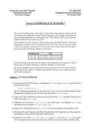
From Use Cases to Objects<br />
Level 1<br />
Level 1 Use Case<br />
Level 2<br />
Level 2<br />
Level 2 Use Cases<br />
Level 3 Level 3<br />
Level 3<br />
Level 3 Use Cases<br />
Level 4 Level 4<br />
Operations<br />
A<br />
B<br />
Participating<br />
Objects<br />
© 2008 Bernd Bruegge <strong>Software</strong> <strong>Engineering</strong> SS 2008<br />
4
From Use Cases to Objects: Why Functional<br />
Decomposition is not Enough<br />
Level 1<br />
Scenarios<br />
Level 2<br />
Level 2<br />
Level 1 Use Cases<br />
Level 3 Level 3<br />
Level 3<br />
Level 2 Use Cases<br />
Level 4 Level 4<br />
Operations<br />
A<br />
© 2008 Bernd Bruegge <strong>Software</strong> <strong>Engineering</strong> SS 2008<br />
B<br />
Participating<br />
Objects<br />
5
Activities during Object Modeling<br />
Main goal: Find the important abstractions<br />
• Steps during object modeling<br />
1. Class identification<br />
• Based on the fundamental assumption that we can<br />
find abstractions<br />
2. Find the attributes<br />
3. Find the operations<br />
4. Find the associations between classes<br />
• Order of steps<br />
• Goal: get the desired abstractions<br />
• Order of steps secondary, only a heuristic<br />
• What happens if we find the wrong abstractions?<br />
• We iterate and revise the model<br />
© 2008 Bernd Bruegge <strong>Software</strong> <strong>Engineering</strong> SS 2008<br />
6
Class Identification<br />
• Approaches<br />
• Application domain approach<br />
• Ask application domain experts to identify relevant<br />
abstractions<br />
• Syntactic approach<br />
• Start with use cases<br />
• Analyze the text to identify the objects<br />
• Extract participating objects from flow of events<br />
• Design patterns approach<br />
• Use reusable design patterns<br />
• Component-based approach<br />
• Identify existing solution classes.<br />
© 2008 Bernd Bruegge <strong>Software</strong> <strong>Engineering</strong> SS 2008<br />
7
Class identification is a Hard Problem<br />
• One problem: Definition of the system<br />
boundary:<br />
• Which abstractions are outside, which abstractions are<br />
inside the system boundary?<br />
• Actors are outside the system<br />
• Classes/Objects are inside the system.<br />
© 2008 Bernd Bruegge <strong>Software</strong> <strong>Engineering</strong> SS 2008<br />
8
There are 3 different types of Objects<br />
• Entity Objects<br />
• Represent the persistent in<strong>for</strong>mation tracked by the<br />
system (Application domain objects, also called<br />
“Business objects”)<br />
• Boundary Objects<br />
• Represent the interaction between the user and the<br />
system<br />
• Control Objects<br />
• Represent the control tasks per<strong>for</strong>med by the system.<br />
© 2008 Bernd Bruegge <strong>Software</strong> <strong>Engineering</strong> SS 2008<br />
9
Example: Modeling A Watch<br />
Year<br />
Month<br />
ChangeDate<br />
Button<br />
LCDDisplay<br />
Day<br />
Entity Objects Control Object Boundary Objects<br />
© 2008 Bernd Bruegge <strong>Software</strong> <strong>Engineering</strong> SS 2008<br />
10
Object Types in UML<br />
• We can use the stereotype mechanism to<br />
distinguish the 3 types of objects<br />
<br />
Year<br />
<br />
Month<br />
<br />
Day<br />
<br />
ChangeDate<br />
<br />
Button<br />
<br />
LCDDisplay<br />
Entity Object Control Object Boundary Object
UML is an Extensible Language<br />
• Stereotypes allow you to extend the vocabulary of the<br />
UML so that you can create new model elements,<br />
derived from existing ones<br />
• Examples: <br />
• Stereotypes can also be used to classify method behavior such<br />
as , or <br />
• To indicate the interface of a subsystem or system, we use the<br />
stereotype (Lecture System Design)<br />
• Stereotypes can also be represented with icons and<br />
graphics:<br />
• This can increase the readability of UML diagrams.<br />
© 2008 Bernd Bruegge <strong>Software</strong> <strong>Engineering</strong> SS 2008<br />
12
Icons <strong>for</strong> Stereotypes<br />
• One can use icons <strong>for</strong> stereotypes<br />
• When the stereotype is applied to a UML model element, the<br />
icon is displayed beside or above the name<br />
These icons were first used in Objectory,<br />
Ivar Jacobsen’s CASE tool <strong>for</strong> OOSE<br />
Year ChangeDate Button<br />
WatchUser<br />
Entity Object Control Object Boundary Object Actor<br />
© 2008 Bernd Bruegge <strong>Software</strong> <strong>Engineering</strong> SS 2008<br />
13
Ivar Jacobson, James Rumbaugh, Grady<br />
Booch (The 3 UML “Amigos”)<br />
Invented use cases,<br />
sequence diagrams<br />
and collaboration<br />
diagrams to model<br />
software controlled<br />
telephone switches<br />
at Ericsson (1967)<br />
Developed the OMT<br />
Notation (Object<br />
Modeling Technique)<br />
Added inheritance to<br />
E/R Modeling, 1991<br />
One of the first OO<br />
modelers<br />
Developed the<br />
Booch Method<br />
(“Objects as clouds”,<br />
1991)<br />
© 2008 Bernd Bruegge <strong>Software</strong> <strong>Engineering</strong> SS 2008<br />
Picture Source http://en.wikipedia.org<br />
14
OMT Notation (Object Modeling Technique)<br />
OMT is no longer an active language. However, it is still<br />
important to know about it , because it is the notation<br />
used in the book “Design Patterns”. <br />
© 2008 Bernd Bruegge <strong>Software</strong> <strong>Engineering</strong> SS 2008<br />
15
Booch Notation<br />
Mapping Booch to OMT:<br />
http://www1.inf.tu-dresden.de/~rm1/booch_omt/booch_omt.html<br />
© 2008 Bernd Bruegge <strong>Software</strong> <strong>Engineering</strong> SS 2008<br />
16
Why do we distinguish 3 Object Types?<br />
• Having three types of object leads to models<br />
that are more resistent (“resilient”) to change<br />
• The interface of a system changes more likely than the<br />
control<br />
• The way the system is controlled changes more likely<br />
than entities in the application domain<br />
• Object types originated in Smalltalk:<br />
• Model, View, Controller (MVC)<br />
Model Entity Object<br />
View Boundary Object<br />
Controller Control Object<br />
© 2008 Bernd Bruegge <strong>Software</strong> <strong>Engineering</strong> SS 2008<br />
17
Smalltalk<br />
• Smalltalk was developed<br />
at Xerox Parc (now<br />
parco.com) in the 1970s.<br />
• Smalltak was used to<br />
prototype the WIMP<br />
(windows, icons, menus,<br />
pointers) interface, the<br />
cornerstone <strong>for</strong> today's<br />
graphical user interfaces.<br />
• Smalltalk was developed by<br />
Adele Goldberg and Alan<br />
Kay.<br />
Picture Source http://en.wikipedia.org<br />
© 2008 Bernd Bruegge <strong>Software</strong> <strong>Engineering</strong> SS 2008<br />
18
How do we find Objects?<br />
• Pick a use case and look at the flow of events<br />
• Do a textual analysis (noun-verb analysis)<br />
• Nouns are candidates <strong>for</strong> objects/classes<br />
• Verbs are candidates <strong>for</strong> operations<br />
• This is also called Abbott’s Technique<br />
• After objects/classes are found, identify their<br />
types<br />
• Identify real world entities that the system needs to<br />
keep track of (FieldOfficer Entity Object)<br />
• Identify real world procedures that the system needs<br />
to keep track of (EmergencyPlan Control Object)<br />
• Identify interface artifacts (PoliceStation Boundary<br />
Object).<br />
© 2008 Bernd Bruegge <strong>Software</strong> <strong>Engineering</strong> SS 2008<br />
19
Example <strong>for</strong> using the Technique<br />
Flow of Events:<br />
• The customer enters the store to buy a<br />
toy. <br />
• It has to be a toy that his daughter likes<br />
and it must cost less than 50 Euro. <br />
• He tries a videogame, which uses a data<br />
glove and a head-mounted display. He likes<br />
it.<br />
• An assistant helps him. <br />
• The suitability of the game depends on the<br />
age of the child. <br />
• His daughter is only 3 years old. <br />
• The assistant recommends another type of<br />
toy, namely the boardgame “Monopoly".<br />
© 2008 Bernd Bruegge <strong>Software</strong> <strong>Engineering</strong> SS 2008<br />
20
Textual Analysis (Abbot’s Technique)<br />
Example<br />
“Monopoly”<br />
Toy<br />
Buy, recommend<br />
is-a<br />
has an<br />
must be<br />
dangerous<br />
enter<br />
Part of speech<br />
Proper noun<br />
Improper noun<br />
Doing verb<br />
being verb<br />
having verb<br />
modal verb<br />
adjective<br />
transitive verb<br />
UML model component<br />
object<br />
class<br />
operation<br />
inheritance <br />
aggregation<br />
constraint<br />
attribute<br />
operation<br />
depends on<br />
intransitive verb<br />
© 2008 Bernd Bruegge <strong>Software</strong> <strong>Engineering</strong> SS 2008<br />
Constraint, class,<br />
association<br />
21
Generating a Class Diagram from Flow of Events<br />
Customer<br />
store ?<br />
enter()<br />
daughter<br />
age<br />
Flow of events:<br />
• The customer enters<br />
the store<br />
to buy a toy. toy It has to be a<br />
toy that his daughter likes and<br />
it must cost less than less 50 than Euro. 50<br />
He tries a videogame, videogame which<br />
uses a data glove and a headmounted<br />
display. He likes it.<br />
suitable<br />
* Toy<br />
toy<br />
price<br />
buy()<br />
like()<br />
videogame<br />
boardgame<br />
An assistant helps him. The<br />
suitability of the game depends <br />
on the age of the child. His<br />
daughter is only 3 years old.<br />
The assistant recommends another<br />
type of toy, type namely of toya boardgame.<br />
The boardgame customer buy the game and<br />
leaves the store
Ways to find Objects 10 31 2008<br />
• Syntactical investigation with Abbot‘s technique:<br />
• Flow of events in use cases<br />
• Problem statement<br />
• Use other knowledge sources:<br />
• Application knowledge: End users and experts know<br />
the abstractions of the application domain<br />
• Solution knowledge: Abstractions in the solution<br />
domain<br />
• General world knowledge: Your generic knowledge and<br />
intuition<br />
© 2008 Bernd Bruegge <strong>Software</strong> <strong>Engineering</strong> SS 2008<br />
23
Order of Activities <strong>for</strong> Object Identification<br />
1. Formulate a few scenarios with help from an<br />
end user or application domain expert<br />
2. Extract the use cases from the scenarios, with<br />
the help of an application domain expert<br />
3. Then proceed in parallel with the following:<br />
• Analyse the flow of events in each use case<br />
using Abbot's textual analysis technique<br />
• Generate the UML class diagram.<br />
© 2008 Bernd Bruegge <strong>Software</strong> <strong>Engineering</strong> SS 2008<br />
24
Steps in Generating Class Diagrams<br />
1. Class identification (textual analysis, domain<br />
expert)<br />
2. Identification of attributes and operations<br />
(sometimes be<strong>for</strong>e the classes are found!)<br />
3. Identification of associations between classes<br />
4. Identification of multiplicities<br />
5. Identification of roles<br />
6. Identification of inheritance<br />
© 2008 Bernd Bruegge <strong>Software</strong> <strong>Engineering</strong> SS 2008<br />
25
Who uses Class Diagrams?<br />
• Purpose of class diagrams<br />
• The description of the static properties of a system<br />
• The main users of class diagrams:<br />
• The application domain expert<br />
• uses class diagrams to model the application<br />
domain (including taxonomies)<br />
• during requirements elicitation and analysis<br />
• The developer<br />
• uses class diagrams during the development of a<br />
system<br />
• during analysis, system design, object design<br />
and implementation.<br />
© 2008 Bernd Bruegge <strong>Software</strong> <strong>Engineering</strong> SS 2008<br />
26
Who does not use Class Diagrams?<br />
• The client and the end user are often not<br />
interested in class diagrams<br />
• Clients usually focus more on project management<br />
issues<br />
• End users usually focus on the functionality of the<br />
system.<br />
© 2008 Bernd Bruegge <strong>Software</strong> <strong>Engineering</strong> SS 2008<br />
27
(Intermediate) Summary<br />
• System modeling<br />
• Functional modeling+object modeling+dynamic modeling<br />
• Functional modeling<br />
• From scenarios to use cases to objects<br />
• Object modeling is the central activity<br />
• Class identification is a major activity of object modeling<br />
• Easy syntactic rules to find classes and objects<br />
• Abbot’s Technique<br />
• Class diagrams are the “center of the universe”<br />
<strong>for</strong> the object-oriented developer<br />
• The end user focuses more on the functional model and<br />
and usability.<br />
© 2008 Bernd Bruegge <strong>Software</strong> <strong>Engineering</strong> SS 2008<br />
28
“Historical” Readings<br />
OMT:<br />
• James Rumbaugh, Michael Blaha, William Premerlani, and<br />
Frederick Eddy. Object-Oriented Modeling and Design with<br />
UML (2nd Edition by Rumbaugh and Blaha), Prentice Hall<br />
1991 and 2004.<br />
OOSE and Use Cases:<br />
• Ivar Jacobson, Magnus Christerson, Patrik Jonsson, Gunnar<br />
Overgaard Object-Oriented <strong>Software</strong> <strong>Engineering</strong>: A Use<br />
Case Driven Approach (ACM Press) Addison-Wesley, 1992,<br />
ISBN 0201544350<br />
Booch Method:<br />
• Booch, Grady (1993). Object-oriented Analysis and Design<br />
with Applications, 2nd ed., Redwood City: Benjamin<br />
Cummings.<br />
© 2008 Bernd Bruegge <strong>Software</strong> <strong>Engineering</strong> SS 2008<br />
29
Developers have different Views on Class<br />
Diagrams<br />
• According to the development activity, a<br />
developer plays different roles:<br />
• Analyst<br />
• System Designer<br />
• Object Designer<br />
• Implementor<br />
• Each of these roles has a different view about<br />
the class diagram (the object model).<br />
© 2008 Bernd Bruegge <strong>Software</strong> <strong>Engineering</strong> SS 2008<br />
30
The View of the Analyst<br />
• The analyst is interested<br />
• in application classes: The associations between<br />
classes are relationships between abstractions in the<br />
application domain<br />
• operations and attributes of the application classes<br />
(difference to E/R models!)<br />
• The analyst uses inheritance in the model to<br />
reflect the taxonomies in the application domain<br />
• Taxonomy: An is-a-hierarchy of abstractions in an<br />
application domain<br />
• The analyst is not interested<br />
• in the exact signature of operations<br />
• in solution domain classes.<br />
© 2008 Bernd Bruegge <strong>Software</strong> <strong>Engineering</strong> SS 2008<br />
31
The View of the Designer<br />
• The designer focuses on the solution of the<br />
problem, that is, the solution domain<br />
• The associations between classes now mean<br />
references (pointers) between classes in the<br />
application or solution domain<br />
• An important design task is the specification of<br />
interfaces:<br />
• The designer describes the interface of classes and the<br />
interface of subsystems<br />
• Subsystems originate from modules (term often used<br />
during analysis):<br />
• Module: a collection of classes<br />
• Subsystem: a collection of classes with an interface<br />
• Subsystems are modeled in UML with a package.<br />
© 2008 Bernd Bruegge <strong>Software</strong> <strong>Engineering</strong> SS 2008<br />
32
Goals of the Designer<br />
• The most important design goals <strong>for</strong> the<br />
designer are design usability and design<br />
reusability<br />
• Design usability: the subsystem interfaces are<br />
usable from as many classes as possible within<br />
in the system<br />
• Design reusability: The subsystem interfaces<br />
are designed in a way, that they can also be<br />
reused by other (future) software systems<br />
=> Class libraries<br />
=> Frameworks<br />
=> Design patterns.<br />
© 2008 Bernd Bruegge <strong>Software</strong> <strong>Engineering</strong> SS 2008<br />
33
The View of the Implementor<br />
• Class implementor<br />
• Must realize the interface of a class in a programming<br />
language<br />
• Interested in appropriate data structures (<strong>for</strong> the<br />
attributes) and algorithms (<strong>for</strong> the operations)<br />
• Class extender<br />
• Interested in how to extend a class to solve a new<br />
problem or to adapt to a change in the application<br />
domain<br />
• Class user<br />
• The class user is interested in the signatures of the<br />
class operations and conditions, under which they can<br />
be invoked<br />
• The class user is not interested in the implementation<br />
of the class.<br />
© 2008 Bernd Bruegge <strong>Software</strong> <strong>Engineering</strong> SS 2008<br />
34
Class Implementor, Class Extender and<br />
Class User<br />
Class User<br />
Call Class<br />
Developer<br />
Class Implementor<br />
Realize Class<br />
Class Extender<br />
Refine Class<br />
© 2008 Bernd Bruegge <strong>Software</strong> <strong>Engineering</strong> SS 2008<br />
35
Why do we distinguish different Users of<br />
Class Diagrams?<br />
• Models often don‘t distinguish between application<br />
domain classes and solution domain classes<br />
• Reason: Modeling languages like UML allow the use of<br />
both types of classes in the same model<br />
• “address book“, “array"<br />
• Preferred: No solution classes in the analysis model<br />
• Many systems don‘t distinguish between the<br />
specification and the implementation of a class<br />
• Reason: Object-oriented programming languages allow<br />
the simultaneous use of specification and implementation<br />
of a class<br />
• Preferred: We distinguish between analysis model and<br />
object design model. The analysis design model does not<br />
contain any implementation specification.<br />
© 2008 Bernd Bruegge <strong>Software</strong> <strong>Engineering</strong> SS 2008<br />
36
Analysis model vs. object design model<br />
• The analysis model is constructed during the<br />
analysis phase<br />
• Main stake holders: End user, customer, analyst<br />
• The class diagrams contains only application domain<br />
classes<br />
• The object design model (sometimes also called<br />
specification model) is created during the object<br />
design phase<br />
• Main stake holders: class specifiers, class<br />
implementors, class extenders and class users<br />
• The class diagrams contain application domain as well<br />
as solution domain classes.<br />
© 2008 Bernd Bruegge <strong>Software</strong> <strong>Engineering</strong> SS 2008<br />
37
Stop! I am lost<br />
© 2008 Bernd Bruegge <strong>Software</strong> <strong>Engineering</strong> SS 2008<br />
38
I cannot follow the lectures. Where are we?<br />
• We have covered Ch 1 - 3<br />
• We are in the middle of Chapter 4<br />
• Functional modeling: Read again Ch 2, pp. 46 - 51<br />
• Structural modeling: Read again Ch 2, pp.52 - 59<br />
• From use cases to class diagrams<br />
• Identify participatory objects in flow of events descriptions<br />
• Exercise: Apply Abbot’s technique to Fig. 5-7, p. 181<br />
• Identify entity, control and boundary objects<br />
• Heuristics to find these types: Ch 5, Section 5.4<br />
• We are now focusing on identyfing classes during<br />
dynamic modeling<br />
© 2008 Bernd Bruegge <strong>Software</strong> <strong>Engineering</strong> SS 2008<br />
39
How do you find classes and objects?<br />
• We have already established several sources <strong>for</strong><br />
class and object identification:<br />
• Application domain analysis: We find classes by talking<br />
to the client and identify abstractions by observing the<br />
end user<br />
• General world knowledge and intuition<br />
• Textual analysis of event flow in use cases (Abbot)<br />
• Today we identify classes and objects from<br />
dynamic models<br />
• Two good heuristics:<br />
1. Actions and activities are candidates <strong>for</strong> public<br />
operations on classes<br />
2. Activity lines in sequence diagrams are candidates <strong>for</strong><br />
objects.<br />
© 2008 Bernd Bruegge <strong>Software</strong> <strong>Engineering</strong> SS 2008<br />
40
Dynamic Modeling<br />
• Definition of a dynamic model:<br />
• Describes the components of the system that have<br />
interesting dynamic behavior<br />
• The dynamic model is described with<br />
• State diagrams: One state diagram <strong>for</strong> each class with<br />
interesting dynamic behavior<br />
• Classes without interesting dynamic behavior are<br />
not modeled with state diagrams<br />
• Sequence diagrams: For modeling the interaction<br />
between classes<br />
• Purpose:<br />
• Detect and supply operations <strong>for</strong> the object model.<br />
© 2008 Bernd Bruegge <strong>Software</strong> <strong>Engineering</strong> SS 2008<br />
41
How do we detect Operations?<br />
• We look <strong>for</strong> objects, who are interacting and<br />
extract their “protocol”<br />
• “How are you?””I am fine”.<br />
• We look <strong>for</strong> objects, who have interesting<br />
behavior<br />
• Star, Banking account<br />
• Good starting point: Flow of events in a use case<br />
description<br />
• From the flow of events we construct the sequence<br />
diagram<br />
• In the sequence diagram we look <strong>for</strong> the “participating<br />
objects”.<br />
© 2008 Bernd Bruegge <strong>Software</strong> <strong>Engineering</strong> SS 2008<br />
42
Flow of Events<br />
• What is an Event?<br />
• Something that happens at a point in time<br />
• An event sends in<strong>for</strong>mation from one object to another<br />
• Events can have associations with each other:<br />
• Temporally related events:<br />
• Event A always “happens be<strong>for</strong>e” event B<br />
• Event B always “happens after” event C<br />
• Unrelated events:<br />
• Events that happen concurrently (A and B can<br />
happen at the same time)<br />
• What is a Flow of Events?<br />
• A sequence of temporally related and unrelated events.<br />
© 2008 Bernd Bruegge <strong>Software</strong> <strong>Engineering</strong> SS 2008<br />
43
Event<br />
• An event is an important abstraction in a<br />
dynamic model. There<strong>for</strong>e we model the events<br />
in a system usually as classes<br />
• Event classes can be grouped in event classes<br />
with a hierarchical structure<br />
• This means, we can define a Event taxonomy<br />
• The term ‘Event’ is also used in two other ways:<br />
• Instance of an event class:<br />
• “Slide 44 shown on Tuesday November 4 at 16:50”.<br />
Event class “Lecture Given”, Subclass “Slide Shown”<br />
• Attribute of an event class<br />
• Mouse click (buttonNr, direction, location)<br />
• Slide Update(3:45 PM, 11/4/2008)<br />
• Train_Leaves(4:45pm, Manhattan)<br />
© 2008 Bernd Bruegge <strong>Software</strong> <strong>Engineering</strong> SS 2008<br />
44
Sequence Diagram<br />
• A sequence diagram is a graphical description of<br />
the flow of events<br />
• The objects participating in the flow of events<br />
are called participating objects<br />
• A good rule of thumb <strong>for</strong> finding participating<br />
objects:<br />
• A event always has a sender and a receiver<br />
• Find the sender and receiver <strong>for</strong> each event<br />
=>These are the objects participating in the use case.<br />
© 2008 Bernd Bruegge <strong>Software</strong> <strong>Engineering</strong> SS 2008<br />
45
An Example<br />
• Assume a “Get SeatPosition” use case with the<br />
following flow of events:<br />
1. Establish connection between smart card and<br />
onboard computer<br />
2. Establish connection between onboard computer and<br />
seat<br />
3. Get current seat position and store on smart card<br />
• Where are the objects?<br />
© 2008 Bernd Bruegge <strong>Software</strong> <strong>Engineering</strong> SS 2008<br />
46
Sequence Diagram <strong>for</strong> “Get SeatPosition”<br />
Smart Card Onboard Computer Seat<br />
1. Establish<br />
connection<br />
between smart<br />
card and onboard<br />
computer<br />
2. Establish<br />
connection<br />
between onboard<br />
computer and seat<br />
(actually seat<br />
sensor)<br />
Establish Connection<br />
Accept Connection<br />
Establish Connection<br />
Accept Connection<br />
time<br />
3. Get current seat<br />
position and store<br />
on smart card.<br />
Get SeatPosition<br />
“500,575,300”<br />
© 2008 Bernd Bruegge <strong>Software</strong> <strong>Engineering</strong> SS 2008<br />
47
Heuristics <strong>for</strong> Sequence Diagrams<br />
• Layout Heuristic:<br />
1st column: Should be the actor of the use case<br />
2nd column: Should be a boundary object<br />
3rd column: Should be the control object that<br />
manages the rest of the use case<br />
• Creation of Objects Heuristic:<br />
1. Create control objects at beginning of the flow of events<br />
2. The control objects then create the boundary objects<br />
• Access of Objects Heuristic:<br />
• Entity objects are accessed by control and boundary objects<br />
• Entity objects should not access boundary or control<br />
objects.<br />
© 2008 Bernd Bruegge <strong>Software</strong> <strong>Engineering</strong> SS 2008<br />
48
ARENA Sequence Diagram: Create Tournament<br />
League<br />
Owner<br />
:Tournament<br />
Boundary<br />
:Arena<br />
:League<br />
newTournament<br />
(league)<br />
setName(name)<br />
«new»<br />
:Announce<br />
Tournament<br />
Control<br />
checkMax<br />
Tournament()<br />
setMaxPlayers<br />
(maxp)<br />
commit()<br />
createTournament<br />
(name, maxp)<br />
create<br />
Tournament<br />
(name, maxp)<br />
«new»<br />
:Tournament<br />
© 2008 Bernd Bruegge <strong>Software</strong> <strong>Engineering</strong> SS 2008<br />
49
Impact on ARENA’s Object Model<br />
• Let’s assume ARENA’s object model contains - at<br />
this modeling stage - the objects<br />
• League Owner, Arena, League, Tournament, Match and<br />
Player<br />
• The Flow of Events identifies 2 new Classes<br />
• Tournament Boundary, Announce_Tournament_Control<br />
© 2008 Bernd Bruegge <strong>Software</strong> <strong>Engineering</strong> SS 2008<br />
50
League Owner<br />
Attributes<br />
Operations<br />
1 *<br />
League<br />
Attributes<br />
Operations<br />
Tournament<br />
Attributes<br />
Operations<br />
Player<br />
* *<br />
Attributes<br />
Operations<br />
© 2008 Bernd Bruegge <strong>Software</strong> <strong>Engineering</strong> SS 2008<br />
Match<br />
Attributes<br />
Operations<br />
51
League Owner<br />
Attributes<br />
Operations<br />
1 *<br />
League<br />
Attributes<br />
Operations<br />
Tournament_<br />
Boundary<br />
Attributes<br />
Operations<br />
Announce_<br />
Tournament_<br />
Control<br />
Attributes<br />
Operations<br />
Tournament<br />
Attributes<br />
Operations<br />
Player<br />
Attributes<br />
* *<br />
Match<br />
Attributes<br />
Operations<br />
© 2008 Bernd Bruegge <strong>Software</strong> <strong>Engineering</strong> SS 2008<br />
Operations<br />
52
Impact on ARENA’s Object Model (2)<br />
• The sequence diagram (slide 49) also supplies us<br />
with many new events<br />
• newTournament(league)<br />
• setName(name)<br />
• setMaxPlayers(max)<br />
• commit<br />
• checkMaxTournament()<br />
• createTournament<br />
• Question: Who owns these events?<br />
• Answer (Heuristic): For each object that receives an<br />
event there should be a public operation in the associated<br />
class<br />
A good choice <strong>for</strong> the name of the operation is<br />
usually the name of the event.<br />
© 2008 Bernd Bruegge <strong>Software</strong> <strong>Engineering</strong> SS 2008<br />
53
League<br />
Owner<br />
Example from the Sequence Diagram<br />
newTournament<br />
(league)<br />
:Tournament<br />
Boundary<br />
:Arena<br />
:League<br />
setName(name)<br />
«new»<br />
:Announce<br />
Tournament<br />
Control<br />
checkMax<br />
Tournament()<br />
setMaxPlayers<br />
(maxp)<br />
commit()<br />
createTournament<br />
(name, maxp)<br />
create<br />
Tournament<br />
(name, maxp)<br />
«new»<br />
:Tournament<br />
© 2008 Bernd Bruegge <strong>Software</strong> <strong>Engineering</strong> SS 2008<br />
54
LeagueOwner<br />
Attributes<br />
Operations<br />
1 *<br />
League<br />
Attributes<br />
Operations<br />
Tournament_<br />
Boundary<br />
Attributes<br />
Operations<br />
Announce_<br />
Tournament_<br />
Control<br />
Attributes<br />
Tournament<br />
Attributes<br />
Operations<br />
createTournament<br />
(name, maxp)<br />
Player<br />
Attributes<br />
* *<br />
Match<br />
Attributes<br />
Operations<br />
© 2008 Bernd Bruegge <strong>Software</strong> <strong>Engineering</strong> SS 2008<br />
Operations<br />
55
What else can we get out of Sequence<br />
Diagrams?<br />
• Sequence diagrams are derived from use cases<br />
• The structure of the sequence diagram helps us<br />
to determine how decentralized the system is<br />
• We distinguish two structures <strong>for</strong> sequence<br />
diagrams (Ivar Jacobson)<br />
• Fork Diagrams and Stair Diagrams<br />
© 2008 Bernd Bruegge <strong>Software</strong> <strong>Engineering</strong> SS 2008<br />
56
Ivar Jacobson in Nuernberg 11.11.08<br />
© 2008 Bernd Bruegge <strong>Software</strong> <strong>Engineering</strong> SS 2008<br />
57
Fork Diagram<br />
• The dynamic behavior is placed in a single<br />
object, usually a control object<br />
• It knows all the other objects and often uses them <strong>for</strong><br />
direct questions and commands<br />
Control<br />
Object<br />
© 2008 Bernd Bruegge <strong>Software</strong> <strong>Engineering</strong> SS 2008<br />
58
Stair Diagram<br />
• The dynamic behavior is distributed. Each object<br />
delegates responsibility to other objects<br />
• Each object knows only a few of the other objects and<br />
knows which objects can help with a specific behavior<br />
© 2008 Bernd Bruegge <strong>Software</strong> <strong>Engineering</strong> SS 2008<br />
59
Fork or Stair?<br />
• Object-oriented supporters claim that the stair<br />
structure is better<br />
• Modeling Advice:<br />
• Choose the stair - a decentralized control structure - if<br />
• The operations have a strong connection<br />
• The operations will always be per<strong>for</strong>med in the<br />
same order<br />
• Choose the <strong>for</strong>k - a centralized control structure - if<br />
• The operations can change order<br />
• New operations are expected to be added as a<br />
result of new requirements.<br />
© 2008 Bernd Bruegge <strong>Software</strong> <strong>Engineering</strong> SS 2008<br />
60
State<br />
• An abstraction of the attributes of a class<br />
• State is the aggregation of several attributes a class<br />
• A state is an equivalence class of all those<br />
attribute values and links that do no need to be<br />
distinguished<br />
• Example: State of a bank<br />
• State has duration<br />
© 2008 Bernd Bruegge <strong>Software</strong> <strong>Engineering</strong> SS 2008<br />
61
State Chart Diagram vs Sequence Diagram<br />
• State chart diagrams help to identify:<br />
• Changes to an individual object over time<br />
• Sequence diagrams help to identify:<br />
• The temporal relationship of between objects over time<br />
• Sequence of operations as a response to one ore more<br />
events.<br />
© 2008 Bernd Bruegge <strong>Software</strong> <strong>Engineering</strong> SS 2008<br />
62
Dynamic Modeling of User Interfaces<br />
• Statechart diagrams can be used <strong>for</strong> the design<br />
of user interfaces<br />
• States: Name of screens<br />
• Actions or activities are shown as bullets under<br />
the screen name<br />
© 2008 Bernd Bruegge <strong>Software</strong> <strong>Engineering</strong> SS 2008<br />
63
Navigation Path Example<br />
Name of Node:<br />
Screen name <br />
Home<br />
• User Selects Books:<br />
<strong>Software</strong> <strong>Engineering</strong><br />
Action or<br />
Activity<br />
List of Books on<br />
<strong>Software</strong> <strong>Engineering</strong><br />
• User scrolls down<br />
Object-Oriented<br />
<strong>Software</strong> <strong>Engineering</strong>,<br />
Bruegge & Dutoit<br />
• User adds book to<br />
Shopping Cart<br />
List of Books on<br />
<strong>Software</strong> <strong>Engineering</strong><br />
• User selects OOSE<br />
© 2008 Bernd Bruegge <strong>Software</strong> <strong>Engineering</strong> SS 2008<br />
64
Practical Tips <strong>for</strong> Dynamic Modeling<br />
• Construct dynamic models only <strong>for</strong> classes with<br />
significant dynamic behavior<br />
• Avoid “analysis paralysis”<br />
• Consider only relevant attributes<br />
• Use abstraction if necessary<br />
• Look at the granularity of the application when<br />
deciding on actions and activities.<br />
© 2008 Bernd Bruegge <strong>Software</strong> <strong>Engineering</strong> SS 2008<br />
65
Model Validation and Verification<br />
• Verification is an equivalence check after<br />
the trans<strong>for</strong>mation of two models<br />
• Validation is the comparison of the model<br />
with reality<br />
• Validation is a critical step in the development<br />
process Requirements should be validated with<br />
the client and the user.<br />
• Techniques: Formal and in<strong>for</strong>mal reviews<br />
(Meetings, requirements review)<br />
• Requirements validation involves several<br />
checks<br />
• Correctness, Completeness, Ambiguity, Realistism<br />
© 2008 Bernd Bruegge <strong>Software</strong> <strong>Engineering</strong> SS 2008<br />
66
Verification vs Validation of models<br />
f R<br />
R<br />
System<br />
Analysis<br />
Design<br />
M Analysis M System<br />
f MA f MS<br />
Object<br />
Design<br />
f MD <br />
M Object<br />
Implemen-<br />
tation<br />
f Impl<br />
M Impl <br />
R<br />
M Analysis<br />
M System<br />
M Object<br />
M Impl<br />
Validation<br />
Verification<br />
Verification<br />
Verification<br />
I<br />
M<br />
R<br />
f M<br />
f R<br />
M<br />
R<br />
I<br />
© 2008 Bernd Bruegge <strong>Software</strong> <strong>Engineering</strong> SS 2008<br />
67
Checklist <strong>for</strong> a Requirements Review (1)<br />
• Is the model correct?<br />
• A model is correct if it represents the client’s view of<br />
the the system<br />
• Is the model complete?<br />
• Every scenario is covered by the model<br />
• Is the model consistent?<br />
• The model does not have components that contradict<br />
each other<br />
• Is the model unambiguous?<br />
• The model describes one system, not many<br />
• Is the model realistic?<br />
• The model can be implemented<br />
© 2008 Bernd Bruegge <strong>Software</strong> <strong>Engineering</strong> SS 2008<br />
68
Checklist <strong>for</strong> the Requirements Review (2)<br />
• Syntactic check of the models<br />
• Check <strong>for</strong> consistent naming of classes, attributes,<br />
methods in different subsystems<br />
• Identify dangling associations (“pointing to nowhere”)<br />
• Identify double- defined classes<br />
• Identify missing classes (mentioned in one model but<br />
not defined anywhere)<br />
• Check <strong>for</strong> classes with the same name but different<br />
meanings<br />
© 2008 Bernd Bruegge <strong>Software</strong> <strong>Engineering</strong> SS 2008<br />
69
Check <strong>for</strong> consistent naming<br />
UML Sequence Diagram<br />
UML Class Diagram<br />
createTournament<br />
(name, maxp)<br />
LeagueOwner<br />
Attributes<br />
Operations<br />
1 *<br />
League<br />
Attributes<br />
Operations<br />
Tournament_<br />
Boundary<br />
Attributes<br />
Operations<br />
Announce_<br />
Tournament_<br />
Control<br />
Attributes<br />
Tournament<br />
Attributes<br />
Operations<br />
Different spellings<br />
in different models<br />
<strong>for</strong> the same operation<br />
Player<br />
Attributes<br />
Operations<br />
© 2008 Bernd Bruegge <strong>Software</strong> <strong>Engineering</strong> SS 2008<br />
makeTournament<br />
(name, maxp)<br />
* *<br />
Match<br />
Attributes<br />
Operations<br />
70
Omissions in some UML Diagrams<br />
Class Diagram<br />
League Owner<br />
Attributes<br />
Operations<br />
1 *<br />
League<br />
Attributes<br />
Operations<br />
Missing class<br />
(The control object<br />
Announce_Tournament<br />
is mentioned in the<br />
sequence diagram)<br />
Tournament_<br />
Boundary<br />
Attributes<br />
Operations<br />
*<br />
Tournament<br />
Attributes<br />
Operations<br />
Missing<br />
Association<br />
(Incomplete<br />
Analysis?)<br />
Player<br />
* *<br />
Attributes<br />
Operations<br />
© 2008 Bernd Bruegge <strong>Software</strong> <strong>Engineering</strong> SS 2008<br />
Match<br />
Attributes<br />
Operations<br />
71
When is a Model Dominant?<br />
• Object model:<br />
• The system has classes with nontrivial states and many<br />
relationships between the classes<br />
• Dynamic model:<br />
• The model has many different types of events: Input,<br />
output, exceptions, errors, etc.<br />
• Functional model:<br />
• The model per<strong>for</strong>ms complicated trans<strong>for</strong>mations (eg.<br />
computations consisting of many steps).<br />
• Which model is dominant in these applications?<br />
• Compiler<br />
• Database system<br />
• Spreadsheet program<br />
© 2008 Bernd Bruegge <strong>Software</strong> <strong>Engineering</strong> SS 2008<br />
72
Dominance of Models<br />
• Compiler:<br />
• The functional model most important<br />
• The dynamic model is trivial because there is only one<br />
type input and only a few outputs<br />
• Database systems:<br />
• The object model most important<br />
• The functional model is trivial, because the purpose of<br />
the functions is to store, organize and retrieve data<br />
• Spreadsheet program:<br />
• The functional model most important<br />
• The dynamic model is interesting if the program allows<br />
computations on a cell<br />
• The object model is trivial.<br />
© 2008 Bernd Bruegge <strong>Software</strong> <strong>Engineering</strong> SS 2008<br />
73
Summary: Analysis<br />
1. What are the trans<strong>for</strong>mations? <br />
Functional Modeling<br />
Create scenarios and use case diagrams <br />
- Talk with the client, observe procedures, workflows, get historical records<br />
2. What is the structure of the system?<br />
Create class diagrams<br />
- Identify objects and classes. <br />
- What are the associations between them? <br />
- What is their multiplicity?<br />
- What are the attributes?<br />
- What operations are defined on the classes?<br />
Object Modeling<br />
3. What is its behavior? <br />
Create sequence diagrams<br />
- Identify senders and receivers<br />
- Show sequence of events exchanged between objects. <br />
- Identify event dependencies and event concurrency.<br />
Create state diagrams <br />
- Only <strong>for</strong> the dynamically interesting objects.<br />
© 2008 Bernd Bruegge <strong>Software</strong> <strong>Engineering</strong> SS 2008<br />
Dynamic Modeling<br />
74
Backup Slides<br />
© 2008 Bernd Bruegge <strong>Software</strong> <strong>Engineering</strong> SS 2008<br />
75
Let’s Do Analysis<br />
• Analyze the problem statement<br />
• Identify functional requirements<br />
• Identify nonfunctional requirements<br />
• Identify constraints (pseudo requirements)<br />
• Build the functional model:<br />
• Develop use cases to illustrate functional requirements<br />
• Build the dynamic model:<br />
• Develop sequence diagrams to illustrate the interaction<br />
between objects<br />
• Develop state diagrams <strong>for</strong> objects with interesting<br />
behavior<br />
• Build the object model:<br />
• Develop class diagrams <strong>for</strong> the structure of the system<br />
© 2008 Bernd Bruegge <strong>Software</strong> <strong>Engineering</strong> SS 2008<br />
76
Problem Statement:<br />
Direction Control <strong>for</strong> a Toy Car<br />
• Power is turned on<br />
• Car moves <strong>for</strong>ward and<br />
car headlight shines<br />
• Power is turned off<br />
• Car stops and headlight<br />
goes out.<br />
• Power is turned on<br />
• Headlight shines<br />
• Power is turned off<br />
• Headlight goes out<br />
• Power is turned on<br />
• Car runs backward with<br />
its headlight shining<br />
• Power is turned off<br />
• Car stops and headlight<br />
goes out<br />
• Power is turned on<br />
• Headlight shines<br />
• Power is turned off<br />
• Headlight goes out<br />
• Power is turned on<br />
• Car runs <strong>for</strong>ward with its<br />
headlight shining<br />
© 2008 Bernd Bruegge <strong>Software</strong> <strong>Engineering</strong> SS 2008<br />
77
Find the Functional Model: Use Cases<br />
• Use case 1: System Initialization<br />
• Entry condition: Power is off, car is not moving<br />
• Flow of events:<br />
1. Driver turns power on<br />
• Exit condition: Car moves <strong>for</strong>ward, headlight is on<br />
• Use case 2: Turn headlight off<br />
• Entry condition: Car moves <strong>for</strong>ward with headlights on<br />
• Flow of events:<br />
1. Driver turns power off, car stops and headlight goes out.<br />
2. Driver turns power on, headlight shines and car does not<br />
move.<br />
3. Driver turns power off, headlight goes out<br />
• Exit condition: Car does not move, headlight is out<br />
© 2008 Bernd Bruegge <strong>Software</strong> <strong>Engineering</strong> SS 2008<br />
78
Use Cases continued<br />
• Use case 3: Move car backward<br />
• Entry condition: Car is stationary, headlights off<br />
• Flow of events:<br />
1. Driver turns power on<br />
• Exit condition: Car moves backward, headlight on<br />
• Use case 4: Stop backward moving car<br />
• Entry condition: Car moves backward, headlights on<br />
• Flow of events:<br />
1. Driver turns power off, car stops, headlight goes out.<br />
2. Power is turned on, headlight shines and car does not<br />
move.<br />
3. Power is turned off, headlight goes out.<br />
• Exit condition: Car does not move, headlight is out<br />
© 2008 Bernd Bruegge <strong>Software</strong> <strong>Engineering</strong> SS 2008<br />
79
Use Cases Continued<br />
• Use case 5: Move car <strong>for</strong>ward<br />
• Entry condition: Car does not move, headlight is out<br />
• Flow of events<br />
1. Driver turns power on<br />
• Exit condition:<br />
• Car runs <strong>for</strong>ward with its headlight shining<br />
© 2008 Bernd Bruegge <strong>Software</strong> <strong>Engineering</strong> SS 2008<br />
80
Use Case Pruning<br />
• Do we need use case 5?<br />
• Let us compare use case 1 and use case 5:<br />
Use case 1: System Initialization<br />
• Entry condition: Power is off, car is not moving<br />
• Flow of events:<br />
1. Driver turns power on<br />
• Exit condition: Car moves <strong>for</strong>ward, headlight is on<br />
Use case 5: Move car <strong>for</strong>ward<br />
• Entry condition: Car does not move, headlight is out<br />
• Flow of events<br />
1. Driver turns power on<br />
• Exit condition:<br />
• Car runs <strong>for</strong>ward with its headlight shining<br />
© 2008 Bernd Bruegge <strong>Software</strong> <strong>Engineering</strong> SS 2008<br />
81
Dynamic Modeling:<br />
Create the Sequence Diagram<br />
• Name: Drive Car<br />
• Sequence of events:<br />
• Billy turns power on<br />
• Headlight goes on<br />
• Wheels starts moving <strong>for</strong>ward<br />
• Wheels keeps moving <strong>for</strong>ward<br />
• Billy turns power off<br />
• Headlight goes off<br />
• Wheels stops moving<br />
• . . .<br />
© 2008 Bernd Bruegge <strong>Software</strong> <strong>Engineering</strong> SS 2008<br />
82
Sequence Diagram <strong>for</strong> Drive Car Scenario<br />
:Headlight<br />
Billy:Driver<br />
:Wheel<br />
Power(on)<br />
Power(on)<br />
Power(off)<br />
Power(off)<br />
Power(on)<br />
Power(on)<br />
Anything wrong with this<br />
sequence diagram? <br />
© 2008 Bernd Bruegge <strong>Software</strong> <strong>Engineering</strong> SS 2008<br />
83
Toy Car: Dynamic Model<br />
Headlight<br />
Wheel<br />
Forward<br />
power<br />
off<br />
Off<br />
power<br />
on<br />
power<br />
on<br />
power<br />
off<br />
On<br />
Stationary<br />
Stationary<br />
power<br />
off<br />
power<br />
on<br />
Backward<br />
© 2008 Bernd Bruegge <strong>Software</strong> <strong>Engineering</strong> SS 2008<br />
84
Toy Car: Object Model<br />
Car<br />
Power<br />
Headlight<br />
Wheel<br />
Status: (On, Off)<br />
TurnOn()<br />
TurnOff()<br />
Status: (On, Off)<br />
Switch_On()<br />
Switch_Off()<br />
Motion: (Forward, <br />
Backward,<br />
Stationary)<br />
Start_Moving()<br />
Stop_Moving()<br />
© 2008 Bernd Bruegge <strong>Software</strong> <strong>Engineering</strong> SS 2008<br />
85
Examples <strong>for</strong> syntactical Problems<br />
• Different spellings in different UML diagrams<br />
• Omissions in diagrams<br />
© 2008 Bernd Bruegge <strong>Software</strong> <strong>Engineering</strong> SS 2008<br />
86
Is this a good Sequence Diagram?<br />
The first<br />
column is<br />
not an actor<br />
It is not<br />
clear where<br />
the<br />
boundary<br />
object is<br />
It is not<br />
clear where<br />
the control<br />
object is<br />
Smart Card Onboard Computer Seat<br />
Establish Connection<br />
Establish Connection<br />
Accept Connection<br />
Accept Connection<br />
Get SeatPosition<br />
“500,575,300”<br />
© 2008 Bernd Bruegge <strong>Software</strong> <strong>Engineering</strong> SS 2008<br />
87
Backup Slides<br />
© 2008 Bernd Bruegge <strong>Software</strong> <strong>Engineering</strong> SS 2008<br />
88
Modeling in Action<br />
• If it is a Face<br />
• What are its Attributes?<br />
• Sad, Happy<br />
• Or is it a Mask?<br />
• Investigate the<br />
functional model<br />
• Who is using it? -> Actors<br />
• Art collector<br />
• Bankrobber<br />
• Carnival participant<br />
• How is it used? -> Event flow<br />
• “Napkin design” of a Mask to be used at the<br />
Venetian Carnival<br />
© 2008 Bernd Bruegge <strong>Software</strong> <strong>Engineering</strong> SS 2008<br />
89
Pieces of an Object Model<br />
• Classes and their instances (“objects”)<br />
• Attributes<br />
• Operations<br />
• Associations between classes and objects<br />
© 2008 Bernd Bruegge <strong>Software</strong> <strong>Engineering</strong> SS 2008<br />
90
Associations<br />
• Types of Associations<br />
• Canonical associations<br />
• Part-of Hierarchy (Aggregation)<br />
• Kind-of Hierarchy (Inheritance)<br />
• Generic associations<br />
© 2008 Bernd Bruegge <strong>Software</strong> <strong>Engineering</strong> SS 2008<br />
91
Attributes<br />
• Detection of attributes is application specific<br />
• Attributes in one system can be classes in<br />
another system<br />
• Turning attributes to classes and vice versa<br />
© 2008 Bernd Bruegge <strong>Software</strong> <strong>Engineering</strong> SS 2008<br />
92
Operations<br />
• Source of operations<br />
• Use cases in the functional model<br />
• General world knowledge<br />
• Generic operations: Get/Set<br />
• Design Patterns<br />
• Application domain specific operations<br />
• Actions and activities in the dynamic model<br />
© 2008 Bernd Bruegge <strong>Software</strong> <strong>Engineering</strong> SS 2008<br />
93
Object vs Class<br />
• Object (instance): Exactly one thing<br />
• This lecture on object modeling<br />
• A class describes a group of objects with similar<br />
properties<br />
• Game, Tournament, mechanic, car, database<br />
• Object diagram: A graphical notation <strong>for</strong><br />
modeling objects, classes and their relationships<br />
• Class diagram: Template <strong>for</strong> describing many instances<br />
of data. Useful <strong>for</strong> taxonomies, patters, schemata...<br />
• Instance diagram: A particular set of objects relating to<br />
each other. Useful <strong>for</strong> discussing scenarios, test cases<br />
and examples<br />
© 2008 Bernd Bruegge <strong>Software</strong> <strong>Engineering</strong> SS 2008<br />
94
Analysis model vs object design model (2)<br />
• The analysis model is the basis <strong>for</strong><br />
communication between analysts, application<br />
domain experts and end users.<br />
• The object design model is the basis <strong>for</strong><br />
communication between designers and<br />
implementors.<br />
© 2008 Bernd Bruegge <strong>Software</strong> <strong>Engineering</strong> SS 2008<br />
95