Review of CMOS image sensors
Review of CMOS image sensors
Review of CMOS image sensors

You also want an ePaper? Increase the reach of your titles
YUMPU automatically turns print PDFs into web optimized ePapers that Google loves.
Microelectronics Journal 37 (2006) 433–451<br />
www.elsevier.com/locate/mejo<br />
<strong>Review</strong> <strong>of</strong> <strong>CMOS</strong> <strong>image</strong> <strong>sensors</strong><br />
M. Bigas a , E. Cabruja a, *, J. Forest b , J. Salvi b<br />
a Centre Nacional de Microelectrònica, IMB-CNM (CSIC), Campus Universitat Autónoma de Barcelona, 08193 Bellaterra, Barcelona, Spain<br />
b Institut d’Informàtica i Aplicacions Campus Montilivi, Universitat de Girona, 17071 Girona, Spain<br />
Received 28 October 2004; received in revised form 29 June 2005; accepted 5 July 2005<br />
Available online 6 September 2005<br />
Abstract<br />
The role <strong>of</strong> <strong>CMOS</strong> Image Sensors since their birth around the 1960s, has been changing a lot. Unlike the past, current <strong>CMOS</strong> Image<br />
Sensors are becoming competitive with regard to Charged Couple Device (CCD) technology. They <strong>of</strong>fer many advantages with respect to<br />
CCD, such as lower power consumption, lower voltage operation, on-chip functionality and lower cost. Nevertheless, they are still too noisy<br />
and less sensitive than CCDs.<br />
Noise and sensitivity are the key-factors to compete with industrial and scientific CCDs. It must be pointed out also that there are several<br />
kinds <strong>of</strong> <strong>CMOS</strong> Image <strong>sensors</strong>, each <strong>of</strong> them to satisfy the huge demand in different areas, such as Digital photography, industrial vision,<br />
medical and space applications, electrostatic sensing, automotive, instrumentation and 3D vision systems.<br />
In the wake <strong>of</strong> that, a lot <strong>of</strong> research has been carried out, focusing on problems to be solved such as sensitivity, noise, power consumption,<br />
voltage operation, speed imaging and dynamic range. In this paper, <strong>CMOS</strong> Image Sensors are reviewed, providing information on the latest<br />
advances achieved, their applications, the new challenges and their limitations. In conclusion, the State-<strong>of</strong>-the-art <strong>of</strong> <strong>CMOS</strong> Image Sensors.<br />
q 2005 Elsevier Ltd. All rights reserved.<br />
Keywords: <strong>CMOS</strong> <strong>image</strong> <strong>sensors</strong>; APS<br />
1. Introduction<br />
1.1. Introduction<br />
Currently, there are many different Imaging Systems<br />
suitable for different purposes, de pending upon their final<br />
application. Digital Cameras, Camcorders, Webcams,<br />
Security cameras or IR-cameras are well-known Imaging<br />
Systems. Moreover, as the purposes are different, the<br />
technologies used differ from each other. This situation<br />
has been possible thanks to the fact that Imaging<br />
Technologies, mainly the ones concerning <strong>CMOS</strong> <strong>image</strong>rs,<br />
have been improving their performance, their functional<br />
capability and their flexibility during last years.<br />
<strong>CMOS</strong> <strong>image</strong> <strong>sensors</strong> have received much attention over<br />
the last decade, because their performance is very promising<br />
compared to CCDs. New horizons can be opened, like ultra<br />
* Corresponding author. Tel.: C34 935947700; fax: C34 935801496.<br />
E-mail addresses: marc.bigas@cnm.es (M. Bigas), enric.cabruja@cnm.<br />
es (E. Cabruja).<br />
0026-2692/$ - see front matter q 2005 Elsevier Ltd. All rights reserved.<br />
doi:10.1016/j.mejo.2005.07.002<br />
low power or camera-on-chip systems. Owing to this<br />
situation and the latest developments within this field, this<br />
paper reviews <strong>CMOS</strong> <strong>image</strong> <strong>sensors</strong> since 1997 in order to<br />
continue and update the review reported by E. Fossum [1].<br />
In order to understand why <strong>CMOS</strong> <strong>image</strong> <strong>sensors</strong> have<br />
emerged as a strong alternative to CCDs, it is important,<br />
first, to highlight the Advantages and Disadvantages <strong>of</strong><br />
<strong>CMOS</strong> <strong>image</strong> <strong>sensors</strong>.<br />
1.2. Advantages and disadvantages<br />
The main Advantages <strong>of</strong> <strong>CMOS</strong> <strong>image</strong>rs are:<br />
1. Low power consumption. Estimates <strong>of</strong> <strong>CMOS</strong> power<br />
consumption range from one-third to more than 100<br />
times less than that <strong>of</strong> CCDs [2]. Besides, they work at<br />
low voltage. <strong>CMOS</strong> <strong>image</strong>rs only need one supply<br />
voltage, instead <strong>of</strong> CCDs, which need 3 or 4.<br />
2. Lower cost compared to CCD’s technology.<br />
3. On chip functionality and compatibility with standard<br />
<strong>CMOS</strong> technology. <strong>CMOS</strong> <strong>image</strong>rs allow monolithical<br />
integration <strong>of</strong> readout and signal processing electronics.<br />
In 2001, a study for Cross Contamination between<br />
<strong>CMOS</strong> Image Sensor and IC product showed no
434<br />
M. Bigas et al. / Microelectronics Journal 37 (2006) 433–451<br />
problems [3]. A sensor can integrate various signal and<br />
<strong>image</strong> processing blocks such as amplifiers, ADCs,<br />
circuits for colour processing and data compression, etc.<br />
on the same chip.<br />
4. Miniaturisation, although important limitations exist,<br />
the level <strong>of</strong> integration is rather high [4].<br />
5. Random access <strong>of</strong> <strong>image</strong> data.<br />
6. Selective read-out mechanism [4,5]<br />
7. High-speed imaging. The flexibility and the possibility<br />
to acquire <strong>image</strong>s in a very short period <strong>of</strong> time [6].<br />
8. To avoid blooming and smearing effects, which are<br />
typical problems <strong>of</strong> CDD technology [6].<br />
As outlined before, despite these advantages, there are<br />
still significant Disadvantages <strong>of</strong> <strong>CMOS</strong> <strong>image</strong> <strong>sensors</strong><br />
compared to CCD technology. Therefore, these problems<br />
need to be solved so that <strong>CMOS</strong> <strong>image</strong> <strong>sensors</strong> can compete<br />
in any area. These disadvantages are:<br />
1. Sensitivity: The basic quality criterion for pixel<br />
sensitivity is the product <strong>of</strong> its Fill Factor and its<br />
Quantum Efficiency (FFxQE) where Fill Factor is the<br />
ratio <strong>of</strong> light-sensitive area to the pixel’s total size, and<br />
Quantum efficiency is the ratio <strong>of</strong> photon-generated<br />
electrons that the pixel captures to the photons incident<br />
on the pixel area. It must be pointed out that Active Pixel<br />
Sensors (APS) have reduced sensitivity to incident light,<br />
due to a limited Fill Factor, hence, less quantum<br />
efficiency.<br />
2. Noise: <strong>CMOS</strong> Image <strong>sensors</strong> suffer from different noise<br />
sources which set the fundamental limits <strong>of</strong> their<br />
performance, especially under low illumination.<br />
3. Dynamic range (DR): Dynamic Range, which is the ratio<br />
<strong>of</strong> the saturation signal to the rms noise floor <strong>of</strong> the<br />
sensor, is limited by the photosensitive-area size,<br />
integration time and noise floor.<br />
4. Less <strong>image</strong> quality than CCD.<br />
In order to overcome the disadvantages outlined before<br />
and, also, to improve the current advantages as well, the<br />
research on <strong>CMOS</strong> <strong>image</strong> <strong>sensors</strong>, since 1997, has been<br />
mostly focused on the following areas:<br />
† Low noise<br />
† High dynamic range<br />
† High sensitivity and High fill factor<br />
† Low power consumption<br />
† Low voltage operation<br />
† High speed imaging<br />
In spite <strong>of</strong> the high number <strong>of</strong> applications <strong>of</strong> the imaging<br />
systems, all <strong>of</strong> them have almost always the same basic<br />
functions: (1) Optical gathering <strong>of</strong> photons (lens), (2)<br />
Wavelength discrimination <strong>of</strong> photons (filter), (3) Detector<br />
for photons to electrons conversion (photodiode), (4)<br />
A method to readout the detector (CCD), (5) Timing,<br />
control, and drive electronics for the <strong>sensors</strong>, (6) Signal<br />
processing electronics such as for Correlated Double<br />
Sampling (CDS) or for color processing, (7) Analog-todigital<br />
conversion, (8) Interface electronics.<br />
1.3. Historical background<br />
1.3.1. Before 1997<br />
<strong>CMOS</strong> <strong>image</strong> <strong>sensors</strong> could not compete in the past with<br />
CCD technology, although the first solid-state <strong>image</strong>rs<br />
presented in the 60 s and early 70 s used MOS diodes as<br />
light sensitive elements and during the 60 s several works<br />
were performed in the solid-state <strong>image</strong> sensor’s field, using<br />
NMOS, PMOS and bipolar processes. [1] For instance,<br />
photodiode <strong>image</strong> <strong>sensors</strong> with MOS scanning circuits were<br />
known from mid 60 s. However, they were not embraced<br />
commercially because <strong>of</strong> poor performance and large pixel<br />
size (for that time) relative to that <strong>of</strong> the CCDs. In fact, even<br />
though <strong>CMOS</strong> <strong>image</strong> <strong>sensors</strong> appeared in 1967, CCDs have<br />
prevailed since their invention in 1970 [7]. Full-analog<br />
CCDs have dominated the vision applications owing to their<br />
superior dynamic range, lower fixed-pattern noise (FPN),<br />
smaller pixels and higher sensitivity to light [2].<br />
In the early 1990s, <strong>CMOS</strong> <strong>image</strong> <strong>sensors</strong> re-emerged as<br />
an alternative to CCDs thanks to the advantages pointed out<br />
before. Passive pixel <strong>CMOS</strong> arrays were the first generation.<br />
Major improvements in signal-to-noise ratio for photodiodes<br />
and charge-injection devices (CIDs) could be made<br />
by adding an amplifier per column or per row. Therefore,<br />
<strong>sensors</strong> that implement a buffer, which acts as simple source<br />
follower, per pixel have been known as active-pixel <strong>sensors</strong><br />
(APS) and represent the second generation <strong>of</strong> <strong>CMOS</strong><br />
<strong>image</strong>rs [8]. <strong>CMOS</strong> APS (Active Pixel Sensors) promised<br />
to provide: lower noise readout, improved scalability to<br />
large array formats and higher speed readout compared to<br />
PPS.<br />
1.3.2. After 1997<br />
Recently, the research has been focusing, mainly, on the<br />
improvement <strong>of</strong> the APS, because APS are the pixel circuit<br />
that have shown better performance and flexibility.<br />
In order to strongly compete with CCD technology, the<br />
aim <strong>of</strong> researchers has been to obtain higher performance<br />
imaging systems based on <strong>CMOS</strong> technology. Therefore,<br />
there have been several reports on improving the fill-factor<br />
(FF) with low power consumption, low voltage operation,<br />
low noise, high speed imaging and high dynamic range.<br />
Moreover, little research has been done on other topics such<br />
as pixel shape optimization [9], pixels on SOI substrate [10],<br />
high resolution [11], APS with variable resolution [12,13],<br />
self-correcting [14,15] and for low light [16–18], etc.<br />
On the other hand, new applications have emerged due to<br />
the <strong>CMOS</strong> <strong>image</strong>r development. Automotive applications,<br />
imaging for cellular or static phones, computer video, space,<br />
medical, digital photography and 3D applications have been<br />
improved. So many applications areas caused that <strong>CMOS</strong>
M. Bigas et al. / Microelectronics Journal 37 (2006) 433–451 435<br />
technology made a breakthrough on two fronts in 2000:<br />
<strong>sensors</strong> for computers and cell phones on the low end, and<br />
ultra high speed, large format imaging on the high-end [19].<br />
Moreover, new technologies and architectures appeared due<br />
to scale effects. For instance, Thin Film on ASIC (TFA)<br />
technology [20–24] and Complementary Active Pixel<br />
Sensors (CAPS) [25–31]. Finally, some studies have been<br />
carried out to study the radiation effects and how radiation<br />
induced dark current in APS [32–39] and the effect <strong>of</strong> hot<br />
carriers [40]. In addition, it is well known that heavy metals<br />
such as Cu, Ni, Fe or Zn, which appear in some <strong>CMOS</strong><br />
<strong>image</strong> sensor processes, can cause defects in silicon and<br />
influence gate oxide quality in VLSI circuits. So the crosscontamination<br />
between <strong>CMOS</strong> <strong>image</strong> sensor and IC<br />
technologies has been studied as well [3].<br />
1.4. CCD technology limitations<br />
CCD technology has prevailed since its invention in<br />
1970, because it provided better solutions to the typical<br />
problems, such as FPN and it had a higher fill factor, smaller<br />
pixel size, larger format, etc. than <strong>CMOS</strong>, which could not<br />
compete with CCD performance. Then, the research has<br />
been mainly focused on CCD technology. Nevertheless,<br />
CCD technology has some limitations: For instance, in a<br />
CCD-based system, the basic function <strong>of</strong>ten consumes<br />
several watts (1–5 W) and is, therefore, a major drain for the<br />
battery. Furthermore, unlike <strong>CMOS</strong> <strong>image</strong> <strong>sensors</strong>, CCD<br />
cannot be monolithically integrated with analog readout and<br />
digital control electronics [1]. New applications have<br />
appeared as well. For instance, in the automotive field, the<br />
<strong>image</strong> sensor has to fulfill the specifications concerning the<br />
temperature range, the range <strong>of</strong> illumination, and the power<br />
dissipation. CCD <strong>image</strong> <strong>sensors</strong> cannot guarantee their<br />
functionality over the whole temperature range required, or<br />
to cover all lighting conditions during daytime. They cannot<br />
operate beyond quite restrictive ranges <strong>of</strong> illumination and<br />
temperature. For instance, a non illuminated CCD is<br />
completely full <strong>of</strong> electrons after roughly 1 min at room<br />
temperature and the dark current doubles approximately<br />
every 7 K. This means that noise drastically increases with<br />
the temperature <strong>of</strong> the chip.<br />
Also there is a need to acquire <strong>image</strong>s in a very short time<br />
for high speed applications, therefore short integration time<br />
is required. This leads to <strong>image</strong> <strong>sensors</strong> equipped with<br />
synchronous shutters in order to avoid blur [6]. Other CCD<br />
typical problems are: Blooming and smearing [6]. CCDs are<br />
high capacitance devices, so they suffer from high power<br />
dissipation. CCDs need many different voltage levels, they<br />
are sensitive to radiation and their readout rate is limited.<br />
1.5. <strong>CMOS</strong> Image <strong>sensors</strong> (APS) as an alternative<br />
to overcome CCDs limitations<br />
<strong>CMOS</strong> <strong>image</strong>rs began to be a strong alternative since<br />
early 90 s (see Fig. 1). Their most important feature was that<br />
they would satisfy the demand for low-power, miniaturised<br />
and cost-effective imaging systems. Moreover, <strong>CMOS</strong><br />
<strong>image</strong> <strong>sensors</strong> <strong>of</strong>fered the possibility to monolithically<br />
integrate a significant amount <strong>of</strong> VLSI electronics on-chip<br />
and reduce component and packaging costs [1].<br />
However, passive pixel <strong>CMOS</strong> arrays were the first<br />
generation. <strong>CMOS</strong> Active Pixel Sensors (APS) have <strong>of</strong>fered<br />
better performance though. Up to now, a lot <strong>of</strong> research and<br />
studies has been done on this topic and <strong>CMOS</strong> APS<br />
technology has demonstrated noise, quantum efficiency, and<br />
dynamic range performance comparable to CCDs [41].<br />
However, CCDs still <strong>of</strong>fer a better <strong>image</strong> quality, especially<br />
for digital still applications. Therefore, CCDs are still<br />
superior to <strong>CMOS</strong> <strong>image</strong> <strong>sensors</strong> as far as signal-to-noise<br />
and dynamic range is concerned. This means that CCDs are<br />
still the first choice for high quality still photography.<br />
In spite <strong>of</strong> the huge work that has been carried out in this<br />
area, more research on reducing the noise and increasing the<br />
sensitivity <strong>of</strong> the <strong>CMOS</strong> <strong>image</strong>rs is needed in order to<br />
compete with industrial and scientific CCDs. For instance, if<br />
the noise issues (mainly reset noise and dark current shot<br />
noise) can be solved with <strong>CMOS</strong> <strong>image</strong>rs, they might be<br />
able to challenge CCDs in digital still applications [5].<br />
Thanks to the fact that there were niches to cover such as<br />
high-speed, motion analysis or detection, etc. [42], <strong>CMOS</strong><br />
APS technology has been growing up and, currently, there<br />
are different kinds <strong>of</strong> pixel circuits depending on their<br />
purpose. For instance, logarithmic APS, capacitive transimpedance<br />
amplifier (CTIA) APS [43], APS with shutter<br />
[44] or complementary active pixel <strong>sensors</strong> CAPS [31].<br />
Currently, there is no <strong>CMOS</strong> <strong>image</strong> sensor that can provide<br />
the global quality <strong>of</strong> a CCD in terms <strong>of</strong> noise, sensitivity,<br />
dynamic range and so on. This means that it is possible to<br />
Fig. 1. Summary <strong>of</strong> the main advantages <strong>of</strong> CCD and <strong>CMOS</strong> <strong>image</strong> <strong>sensors</strong>.
436<br />
M. Bigas et al. / Microelectronics Journal 37 (2006) 433–451<br />
reach or improve one or two <strong>of</strong> their characteristics with<br />
a specific architecture, but not all together.<br />
1.6. New applications-new challenges<br />
The improvement <strong>of</strong> <strong>CMOS</strong> <strong>image</strong> <strong>sensors</strong> has opened<br />
up new application areas [45], owing to the lower cost <strong>of</strong><br />
<strong>CMOS</strong> <strong>image</strong> <strong>sensors</strong>. They can compete with CCDs in<br />
applications such as IR-vision (systems for automobile<br />
drivers under fog and night driving conditions, security<br />
cameras, baby monitors that can ‘see’ in the dark, etc.)<br />
Besides these, imaging or vision systems for X-ray,<br />
space, medical, 3D, consumer electronics, automotive or<br />
low-light applications are required, and most <strong>of</strong> them need<br />
highly integrated imaging systems, so <strong>CMOS</strong> <strong>image</strong> <strong>sensors</strong><br />
are well situated to jump into the market.<br />
Moreover, imaging or vision systems have to <strong>of</strong>fer, in<br />
order to be ideal, good imaging performance with low noise,<br />
no lag, no smear, good blooming control, random access,<br />
simple clocks and fast readout rates.<br />
1.7. <strong>CMOS</strong> Image <strong>sensors</strong> limitations and device<br />
scaling considerations<br />
1.7.1. Industry trend<br />
The technology has advanced from a 2 mm <strong>CMOS</strong> in<br />
1993 to 0.25 mm in 1996 [4] and less than 0.1 mm will also<br />
be possible. So, considering scaling effects has been<br />
necessary in order to know where and which are the limits<br />
<strong>of</strong> <strong>CMOS</strong> <strong>image</strong>rs.<br />
Some Scaling Considerations were studied in 1996[46]<br />
and in 1997[4]. The question was whether the <strong>image</strong> sensing<br />
performance <strong>of</strong> <strong>CMOS</strong> <strong>image</strong>rs would get better or worse as<br />
the technology would be scaled. The question arose because<br />
if <strong>CMOS</strong> <strong>image</strong>rs would scale down as fast as industry<br />
standard <strong>CMOS</strong> technologies, <strong>CMOS</strong> <strong>image</strong>rs would<br />
achieve a smaller pixel size than CCDs during the following<br />
years [4]. Anyway, it seemed to be clear that ‘standard ’<br />
<strong>CMOS</strong> technology, which provided good imaging performance<br />
at 2–1 mm without any process change, would need<br />
some modifications in its fabrication process and innovations<br />
on the pixel architecture in order to enable <strong>CMOS</strong><br />
<strong>image</strong>rs to perform good quality imaging when using the<br />
0.25 mm generation technology and beyond [1]. In fact,<br />
<strong>CMOS</strong> <strong>image</strong>rs could not be scaled down using standard<br />
<strong>CMOS</strong> technology because scaling effects increase leakage<br />
current and reduce dynamic range. That is to say that<br />
performance was getting worse. Thus, technological<br />
changes in <strong>CMOS</strong> technology are needed in order to reach<br />
the imaging performance <strong>of</strong> CCDs with a <strong>CMOS</strong> <strong>image</strong>r.<br />
In 2000 [20] a scaling perspectives study was done and,<br />
certainly, new technological processes appeared, such as<br />
PPD [20] and TFA <strong>image</strong>rs [20–24] (See Fig. 2). Later,<br />
CAPS appeared as well [25–31]. TFA <strong>image</strong>rs are immune<br />
to negative scaling impacts on sensitivity. Even more, they<br />
Fig. 2. Downscaling <strong>of</strong> sensitivity with pixel options.<br />
<strong>of</strong>fer high sensitivity and high dynamic range. Nevertheless<br />
this technology is not suitable down to 0.1 mm.<br />
Thus, it has been demonstrated the limitation <strong>of</strong><br />
conventional APS, because conventional pixel architecture<br />
(APS) cannot work properly with a 0.1 mm technology or<br />
below because the low power <strong>of</strong> these technologies implies<br />
a decrease in the saturation level and in the light sensitivity<br />
that it is not acceptable. Nevertheless, an alternative<br />
architecture called CAPS (Complementary APS) came on<br />
scene [25–31]. They are a possible way to design a highly<br />
integrated, high performance <strong>CMOS</strong> <strong>image</strong> sensor in the<br />
deep sub-quarter micron technology, because CAPS<br />
architecture has a very attractive low-voltage operation<br />
capability. For instance 1.0 V [25,26,29,30] Moreover, the<br />
possibility to reach low power and low voltage consumption<br />
depends on the capability to scale down the current<br />
technology.<br />
2. <strong>CMOS</strong> <strong>image</strong> <strong>sensors</strong><br />
<strong>CMOS</strong> <strong>image</strong> <strong>sensors</strong> are mixed-signal circuits containing<br />
pixels, analog signal processors, analog-to-digital<br />
converters, bias generators, timing generators, digital logic<br />
and memory.<br />
2.1. Overall architecture<br />
There are several <strong>CMOS</strong> <strong>image</strong>r topologies depending<br />
on their purpose. Nevertheless, <strong>CMOS</strong> <strong>image</strong>rs architecture<br />
can be divided into four main blocks, as Fig. 3 shows.<br />
1. Pixel Array<br />
2. Analog Signal Processors<br />
3. Row and Column Selector<br />
4. Timing and Control
M. Bigas et al. / Microelectronics Journal 37 (2006) 433–451 437<br />
Fig. 4. A photodiode-type PPS schematic.<br />
2.2. Pixel circuits<br />
Fig. 3. <strong>CMOS</strong> <strong>image</strong> sensor floorplan.<br />
2.2.1. Traditional <strong>image</strong>rs or photodetectors<br />
1. Photodiodes: Semiconductor devices responsive to high<br />
energy particles and photons. They operate by absorption<br />
<strong>of</strong> photons or charged particles and the collected<br />
electrons which decrease the voltage across the<br />
photodiode in a proportional basis to the incident<br />
power. Currently, photodiode <strong>CMOS</strong> pixels are the<br />
most popular ones.<br />
2. Photogates (PG) or CID (Charge-injection device):<br />
Semiconductor devices that also collect the photongenerated<br />
electrons, but only when the photogate is<br />
biased to a high potential.<br />
3. CCD (Charge-coupled device): Device architecture<br />
based on series and parallel connection <strong>of</strong> capacitors,<br />
which are made using a dedicated semiconductor<br />
process.<br />
2.2.2. Pixel circuits<br />
Pixel circuits are mainly divided into active pixels (APS)<br />
and passive pixels (PPS). APS are <strong>sensors</strong> that implement a<br />
buffer per pixel. This buffer is as simple as adding a sourcefollower.<br />
Currently, APS are the predominant devices,<br />
although in some cases PPS are also used.<br />
2.2.2.1. Passive pixels (PPS). They were the first <strong>CMOS</strong><br />
<strong>image</strong>rs. They are based on photodiodes without internal<br />
amplification. In these devices each pixel consists <strong>of</strong> a<br />
photodetector (e.g. photodiode), and a transistor in order to<br />
connect it to a readout structure (See Fig. 4). Then, after<br />
adressing the pixel by opening the row-select transistor<br />
(RS), the pixel is reset along the bit line and RS. In spite <strong>of</strong><br />
the small pixel size capability and a large fill factor, they<br />
suffer from low sensitivity and high noise [20] due to the<br />
large column’s capacitance with respect to the pixel’s one.<br />
2.2.2.2. Active pixels (APS). APS are <strong>sensors</strong> that implement<br />
a buffer per pixel. This buffer is a simple source-follower. It is<br />
well known that the insertion <strong>of</strong> a buffer/amplifier into the<br />
pixel improves the performance <strong>of</strong> the pixel. Power dissipation<br />
is minimal and, generally, less than CCD’s, because<br />
each amplifier is only activated during readout. Nevertheless,<br />
it must be noted APS technology has some disadvantages:<br />
Conventional APS suffer from a high level <strong>of</strong> fixed pattern<br />
noise (FPN) due to wafer process variations that cause<br />
differences in the transistor thresholds and gain characteristics.<br />
A solution is to use a Correlated Double Sampling<br />
(CDS) circuit, which can almost eliminate the threshold<br />
variations that cause <strong>of</strong>fsets in the video background.<br />
2.2.2.3. Photodiode (PD) type APS. The photodiode-type<br />
(PD) APS is considered as standard and it was described by<br />
Noble in 1968 [1,20] (See Fig. 5a). It consists <strong>of</strong> threetransistor:<br />
a reset transistor, for resetting the photodiode<br />
voltage; and a source follower with select transistor, for<br />
buffering the photodiode voltage onto a vertical-column<br />
bus. The PD APS is suitable for most mid low-performance<br />
applications.<br />
2.2.2.4. Photogate(PG) type APS. It was introduced later<br />
than PD APS, in 1993 [1,20] and it employs the principle <strong>of</strong><br />
operation <strong>of</strong> CCDs concerning integration transport and<br />
readout inside each pixel. Its transfer <strong>of</strong> charge and<br />
correlated double sampling permits a low noise operation.<br />
Thus, it is suitable for high performance and low light<br />
applications. A typical schematic is shown in Fig. 5c.<br />
2.2.2.5. Logarithmic APS. Non-linear output <strong>of</strong> the sensor<br />
can be desirable. This fact permits an increase on the intrascene<br />
dynamic range. Logarithmic APS are suitable for<br />
High Dynamic Range applications, although they suffer<br />
from large FPN. Owing to this fact, currently, they are not as<br />
used as before. It must be pointed out that they are used a lot<br />
in silicon retinas. A typical schematic is shown in the<br />
Fig. 5b.<br />
2.2.2.6. CTIA APS pixels. As highlighted before, conventional<br />
APS suffer a high level <strong>of</strong> FPN. Thus, reducing FPN<br />
has been a challenge for quite a while and some solutions
438<br />
M. Bigas et al. / Microelectronics Journal 37 (2006) 433–451<br />
Fig. 5. (a) A photodiode- type APS schematic, (b) A photodiode- type logarithmic APS schematic, (c) A photogate- type APS schematic, (d) Photodiode- type<br />
shutter APS schematic, (e) TFA pixel, (f) A photodiode- type CAPS schematic, (g) A photodiode- type Low FPN CTIA APS schematic (h) A photodiode- type<br />
High FPN CTIA APS schematic.
M. Bigas et al. / Microelectronics Journal 37 (2006) 433–451 439<br />
have been reported. For instance, capacitive transimpedance<br />
amplifier (CTIA) pixels can achieve low FPN [43]. Besides<br />
this, the high gain and low read noise are advantages <strong>of</strong><br />
using CTIAs as well. Fig. 5h and g show a high FPN and a<br />
low FPN CTIA APS pixel schematics respectively.<br />
2.2.2.7. Pinned photodiode (PPD) pixel. The pinned<br />
photodiode [20], which was previously used in chargecoupled<br />
devices, was proposed early during the development<br />
<strong>of</strong> <strong>CMOS</strong> active-pixel <strong>image</strong> <strong>sensors</strong>. Besides lower<br />
pixel noise, the pinned photodiode <strong>of</strong>fers reduced dark<br />
current. Therefore, they are a PG’s alternative, because their<br />
architecture <strong>of</strong>fers higher sensitivities than PG.<br />
2.2.2.8. TFA pixels. The thin film on ASIC (TFA) pixels<br />
were developed in order to improve sensitivity [20–24].<br />
They consist <strong>of</strong> an amorphous silicon (a-Si:H) multilayer<br />
system that is deposited on top <strong>of</strong> an ASIC.<br />
Their absorption coefficient for visible light is approximately<br />
20 times bigger than crystalline’s silicon (c-Si). In<br />
fact, TFA pixels are suitable for High Dynamic Range<br />
applications. A typical TFA structure pixel is shown in<br />
Fig. 5e.<br />
2.2.2.9. Complementary active pixels <strong>sensors</strong> CAPS. CAPS<br />
are a possible way to manufacture a highly integrated, high<br />
performance <strong>CMOS</strong> <strong>image</strong> sensor in the deep sub-quarter<br />
micron technology. Furthermore, CAPS architecture has<br />
low power consumption and a high low-voltage operation<br />
capability. A typical schematic is shown in Fig. 5f. The<br />
main new features are that the reset transistor is replaced by<br />
a PMOS. In addition, a complementary signal path is<br />
implemented and the pixel gives out two signal path<br />
outputs: V outn and V outp [25–31].<br />
2.2.2.10. Other pixels. There is more pixel architectures<br />
[47], due to the huge number <strong>of</strong> possible applications. For<br />
instance, pixel circuits suitable for high speed operation by<br />
adding a shutter transistor [44] (see Fig. 5d). Also Diericks<br />
(Fillfactory) introduced a novel 100% fill factor pixel.<br />
Overall, PG, PPD and TFA are detector structures to<br />
improve the sensitivity. Nevertheless, TFA provides<br />
significantly better values than PPD due to the higher fill<br />
factor and higher quantum efficiency [20].<br />
2.3. Analog signal processing<br />
Analog signal processing circuits are used in order to<br />
improve the performance and functionality <strong>of</strong> <strong>CMOS</strong> <strong>image</strong><br />
<strong>sensors</strong>. However, they tend to involve less pixel density<br />
and increase the chip area due to the added functions. Some<br />
research has been done to overcome these problems [48].<br />
Firstly, there are some well known traditional signal<br />
processing systems. For instance, additional analog-signalprocessing<br />
circuitry located at the periphery <strong>of</strong> the array<br />
permits the suppression <strong>of</strong> both, temporal and fixed-pattern<br />
noise. As an example, Correlated Double Sampling (CDS)<br />
or Double Differencing Sampling (DDS) suppress FPN [49,<br />
43,50,51]. Others achieve high SNR [52] and ADC for<br />
camera-on-a-chip. Secondly, there are also several signal<br />
processing systems depending on the application. For<br />
instance, signal processing such as K-winners-take-all, are<br />
suitable for 3D vision systems [53–58] and subpixel<br />
accuracy [59–65]. Smoothing [66], motion detection [67–<br />
69], programmable amplification, multiresolution imaging<br />
[70], video compression [71], dynamic range enhancement,<br />
discrete cosine transform (DCT), intensity sorting, etc. are<br />
other signal processing systems.<br />
2.4. Readout methods<br />
Readout methods have an important influence in the<br />
sensor performance. Thus, there are several readout<br />
methods depending on the desirable application. The main<br />
requirements are:<br />
1. low power dissipation<br />
2. high resolution<br />
3. good linearity<br />
4. stable detector bias<br />
5. low noise<br />
6. high injection efficiency<br />
7. small pixel size<br />
8. good dynamic range<br />
APS readout structures fulfil 4 and 8 requirements, but<br />
not 3 and 7. On the other hand PPS readout structure fulfils 7<br />
and not 3, 4, 6 and 8. Finally, share-buffered direct-injection<br />
(SBDI) [72] readout structure combine both <strong>image</strong>rs<br />
characteristics.<br />
Therefore, it is possible to find suitable traditional<br />
readout methods for low FPN [73–76], for high frame<br />
rates [73], to increase linearity and DR [72], with high SNR<br />
and ultrahigh- sensitivity [77,78] and for infrared detectors<br />
[79]. Finally, there are also specialised readout methods<br />
suitable for ultra high sensitivity, for focal plane array, for<br />
X-ray imaging, for an emission-transmission medical<br />
imaging systems, for low-light levels, detectors with selftriggered<br />
readout, <strong>of</strong>fset-free column readout circuit and<br />
transversal-readout architecture<br />
2.5. Noise sources<br />
<strong>CMOS</strong> Image <strong>sensors</strong> suffer from several noise sources.<br />
They set the fundamental limits on <strong>image</strong> sensor performance,<br />
especially under low illumination and in video<br />
applications. Therefore it is important to have an overview<br />
<strong>of</strong> all <strong>of</strong> them [80].<br />
The noise sources in <strong>CMOS</strong> <strong>image</strong>rs can be divided into<br />
Temporal Noise [81] and Fixed Pattern Noise (FPN)[43].
440<br />
M. Bigas et al. / Microelectronics Journal 37 (2006) 433–451<br />
2.5.1. Temporal noise<br />
It can be divided into different kinds <strong>of</strong> noise, depending<br />
on its source:<br />
† Pixel noise: photon shot noise, reset or kT/C noise<br />
(which is the thermal noise resulting from resetting after<br />
each pixel’s readout. The k is Boltzmann’s constant, T is<br />
the absolute temperature; and C is the junction parasitic<br />
capacitance), dark current shot noise and MOS device<br />
noise (thermal, 1/f or flicker, etc.)<br />
† Column Amplifier noise<br />
† Programmable gain amplifier noise<br />
† ADC noise<br />
† Overall temporal noise, noise floor or reading noise.<br />
2.5.2. Fixed pattern noise (FPN)<br />
It has been a huge <strong>CMOS</strong> <strong>image</strong>rs’ limitation. FPN is the<br />
fixed variation in the output between pixels when a uniform<br />
input is applied. In a perfect <strong>image</strong> sensor, each pixel should<br />
have the same output provided that the same input is<br />
applied, but in current <strong>image</strong> <strong>sensors</strong> the output <strong>of</strong> each<br />
sensor is different. FPN does not change as a function <strong>of</strong><br />
time and can be characterized, assuming a linear pixel<br />
response, as a variation in the <strong>of</strong>fset and gain at each pixel.<br />
VijðtÞ Z GijXijðtÞ COi; j<br />
V output,<br />
G gain <strong>of</strong> pixel,<br />
X input,<br />
O <strong>of</strong>fset <strong>of</strong> pixel,<br />
Gain FPN pixel to pixel variation <strong>of</strong> Gij,<br />
Offset FPN pixel to pixel variation <strong>of</strong> Oij.<br />
3. Latest developments in the field <strong>of</strong> <strong>CMOS</strong> <strong>image</strong>rs<br />
The research has been mainly focused on APS in areas<br />
like Low noise, High dynamic range, High sensitivity and<br />
High fill factor, Low power consumption, Low voltage<br />
operation, High speed imaging. To remark is that all these<br />
features are difficult to achieve in one design. Hence,<br />
depending on the application, one feature will have more<br />
priority than another one.<br />
Secondly, with respect to the noise floor the use <strong>of</strong> a linear<br />
readout is more suitable than a logarithmic one. So Dynamic<br />
Range <strong>of</strong> <strong>CMOS</strong> APS is strongly managed by the readout<br />
method. Finally, the photosensitive-area size is an important<br />
issue because <strong>of</strong> the well-known scaling effects.<br />
The major problem <strong>of</strong> artificial <strong>image</strong> acquisition has<br />
been the extraordinary high optical dynamic range <strong>of</strong><br />
natural scenes. For instance, the human vision system<br />
exhibits an enormous optical dynamic range <strong>of</strong> about<br />
200 dB, due to the fact that it can adapt to an extremely high<br />
range <strong>of</strong> light intensity levels [83]. Nevertheless, artificial<br />
<strong>image</strong>rs have been much poorer in this aspect. With<br />
conventional CCD <strong>sensors</strong> it is hard to reach high dynamic<br />
range and <strong>CMOS</strong> <strong>image</strong>rs with logarithmic response suffer<br />
from excessive FPN and temperature drift. For instance, in<br />
year 2000 the conventional CCD <strong>image</strong>rs exhibited usually<br />
a DR <strong>of</strong> about 50–70 dB only and on the other hand, <strong>CMOS</strong><br />
<strong>image</strong>rs would achieve better DR, up to 140 dB, than CCDs<br />
[82], although they used logarithmic readout, which has<br />
some disadvantages such as a high FPN.<br />
In fact, some research has been done to obtain <strong>CMOS</strong><br />
<strong>image</strong> <strong>sensors</strong> with high dynamic range:<br />
3.1.1. Logarithmic<br />
The use <strong>CMOS</strong> <strong>image</strong>rs with logarithmic readout or the<br />
non-linear output <strong>of</strong> the logarithmic pixel provides higher<br />
dynamic range (see Fig. 6). Nevertheless, logarithmic<br />
response has a large FPN and slower response time for<br />
low light levels, which bring down the <strong>image</strong> quality. Thus,<br />
some systems based on logarithmic response have been<br />
developed in order to <strong>of</strong>fer high DR with low FPN. For<br />
instance, in 1998, the University <strong>of</strong> Heidelberg proposed a<br />
<strong>CMOS</strong> camera chip with logarithmic response and selfcalibrating<br />
FPN correction [84]. Its results showed a<br />
significant FPN reduction. Fraunh<strong>of</strong>er Institute <strong>of</strong> Microelectronic<br />
Circuits and Systems <strong>of</strong> Duisburg suggested also<br />
a <strong>CMOS</strong> <strong>image</strong>r with Local Brightness adaptation [85].<br />
It used logarithmic <strong>image</strong> <strong>sensors</strong> in order to reach high DR<br />
and FPN was also compensated. In year 2000, S. Kavadias<br />
reported a technique to remove the high FPN, due to its<br />
logarithmic response [86]. This <strong>CMOS</strong> <strong>image</strong> sensor, which<br />
3.1. High dynamic range (DR)<br />
The ratio <strong>of</strong> the saturation signal to the rms noise floor <strong>of</strong><br />
the sensor is known as dynamic range. This is limited by the<br />
photosensitive-area size, integration time and noise floor,<br />
which is the noise generated in the pixel and the signal<br />
processing electronics. DR is limited by the integration time,<br />
although high dynamic range <strong>image</strong> readout can be achieved<br />
by using different exposure or integration times [82].<br />
Fig. 6. Photoconversion characteristics: linear vs logarithmic.
M. Bigas et al. / Microelectronics Journal 37 (2006) 433–451 441<br />
was based on an active pixel structure, employed on-chip<br />
calibration and achieved a DR <strong>of</strong> 120 dB and the FPN was<br />
2,5% <strong>of</strong> the output signal range. Finally in year 2003 a<br />
multiresolution scheme and a cost-effective architecture for<br />
nonlinear analog-to-digital conversion was presented. These<br />
two features combined together improve the <strong>sensors</strong> quality<br />
under low light intensity [87].<br />
3.1.2. Linear<br />
On the other hand, using <strong>CMOS</strong> <strong>image</strong>rs with linear<br />
readout can improve FPN, even though they can achieve<br />
lower DR (see Fig. 6) than logarithmic ones. For instance, in<br />
1999 a new design, a 1280!1024 digital <strong>CMOS</strong> <strong>image</strong><br />
sensor with enhanced dynamic range, was reported [51].<br />
The response was linear, low FPN was achieved and DR<br />
was <strong>of</strong> 69 dB. In year 2000 a <strong>CMOS</strong> <strong>image</strong> sensor for<br />
automotive applications was proposed [83]. It <strong>of</strong>fered a high<br />
dynamic range up to 120 dB and an excellent <strong>image</strong> quality<br />
due to its linear readout. Furthermore, it had good<br />
temperature behavior up to 85 8C. In year 2002 a high<br />
dynamic <strong>CMOS</strong> <strong>image</strong>r with spiking pixels, pixel-level<br />
ADC, and linear characteristics was reported [88]. It had a<br />
DR <strong>of</strong> 93 dB, although 120 dB was expected. Finally, it is<br />
reported <strong>of</strong> a mechanism [82], using linear readout, capable<br />
for adjusting its sensitivity depending on the absolute<br />
illumination level, like human vision. This is reached by<br />
using different integration times. The results demonstrate<br />
that with 1 integration time, a DR <strong>of</strong> 61 dB is reached. In<br />
contrast, with two integration times, the DR is <strong>of</strong> 92 dB.<br />
3.1.3. Combined<br />
In 1998, the University <strong>of</strong> Waterloo reported a <strong>CMOS</strong><br />
APS with combined linear and logarithmic mode operation<br />
[89]. The results showed that it had good linearity, in the<br />
linear mode operation, and it reached wide dynamic range in<br />
the logarithmic mode.<br />
So the issue is to determine which is the more convenient<br />
readout method in each application. Nevertheless, using<br />
linear readout methods with different integration times<br />
seems to be more suitable.<br />
3.1.4. TFA technology<br />
As outlined before, TFA technology [23,24] is suitable<br />
for achieving a high dynamic range and a high fill factor. In<br />
1999–2000, T. Lulé reported a 100.000 pixel <strong>image</strong>r in TFA<br />
technology [21,22]. The main feature was that every pixel<br />
contained an automatic shutter, which adapted the integration<br />
time to the local intensity. This allowed obtaining a<br />
high DR <strong>of</strong> 120 dB.<br />
3.2. High sensitivity (High fill-factor (FF) and high<br />
quantum efficiency)<br />
3.2.1. Background<br />
The basic quality criterion for pixel sensitivity is<br />
the product <strong>of</strong> its Fill Factor and its Quantum Efficiency<br />
(FF!QE). Where Fill Factor is the ratio <strong>of</strong> light-sensitive<br />
area to the pixel’s total size; also known as aperture<br />
efficiency, and Quantum efficiency is the ratio <strong>of</strong> photongenerated<br />
electrons that the pixel captures to the photons<br />
incident on the pixel area. Photons are lost for conversion<br />
due to: reflection on dielectrics, no absorption in the<br />
acquisition layer and loss <strong>of</strong> charges and recombination.<br />
It is well known that a good <strong>image</strong> quality is obtained if<br />
most <strong>of</strong> the chip area is dedicated to the photodetectors.<br />
Therefore in order to achieve a good <strong>image</strong> quality, a high<br />
Fill Factor (FF) is needed. Unlike CCDs, which achieve<br />
around 100% FF [90,91], <strong>CMOS</strong> APS FF are limited,<br />
because each pixel has an area devoted to the <strong>CMOS</strong><br />
readout circuitry. Around 30% FF is a kind <strong>of</strong> standard. In<br />
<strong>CMOS</strong> APS pixel, the Fill Factor is limited by: (a)<br />
shadowing by metals or silicides, (b) collection <strong>of</strong> photons<br />
by the insensitive junctions <strong>of</strong> the active pixel, (c) the<br />
relatively small size <strong>of</strong> the useful photo-sensitive junction,<br />
(d) recombination <strong>of</strong> photo-generated carriers with majority<br />
carriers, limiting the diffusion length. Besides this, a high fill<br />
factor allows shorter exposure times for a given pixel size or<br />
smaller pixel sizes for a given sensitive area. Thus, FF plays<br />
an important role in the scaling perspectives and <strong>image</strong>r’s<br />
performance.<br />
In the wake <strong>of</strong> that, a lot <strong>of</strong> research has been done to<br />
increase the fill factor <strong>of</strong> <strong>CMOS</strong> APS. There are different<br />
methods used to improve the FF: one is to design active<br />
pixels with larger photodiodes, although small pixels can<br />
not be made and large photodiodes have low charge<br />
conversion sensitivity due to their higher capacitance [92].<br />
The other method is to make passive pixels, but their<br />
performance with respect to active pixels is worse. On the<br />
other hand, microlenses, which help funneling photons to<br />
the light-sensitive portion <strong>of</strong> the pixel [93,1], are another<br />
alternative to overcome this problem. They could reach up<br />
to 90% Fill Factor. In spite <strong>of</strong> this 90% Fill Factor, they have<br />
some disadvantages such as the reduction <strong>of</strong> efficiency as<br />
microlens dimension decreases. In fact, some high fill-factor<br />
designs based on <strong>CMOS</strong> APS exist, which can enhance the<br />
FF: A. Bermak developed a 46% Fill Factor native<br />
logarithmic pixel [94] in 0.7 mm <strong>CMOS</strong> technology in<br />
2000. In 2002, the Georgia Institute <strong>of</strong> Technology achieved<br />
a fill factor greater than 40% by using a matrix transform<br />
<strong>image</strong>r [95] Also in 2002, National Tsing-Hua University<br />
described an APS, with a fill factor <strong>of</strong> 55%, made in<br />
0.25 mm technology [96]. In addition, this device has a high<br />
DR <strong>of</strong> 120 dB, thanks to its innovative tuneable injection<br />
current compensation architecture and a voltage operation<br />
<strong>of</strong> 1.9 V.<br />
Finally, it is important to consider the downscaling<br />
effects, because small pixels mean lower light sensivity and<br />
dynamic range. Thus, conventional APS technology is<br />
limited. Nevertheless innovative architectures, ideas and<br />
technologies reaching a fill factor up to 90–100% have<br />
appeared: For instance, in 1997 Dierickx [97,98] introduced<br />
a near 100% Fill Factor <strong>CMOS</strong> active pixel, which was
442<br />
M. Bigas et al. / Microelectronics Journal 37 (2006) 433–451<br />
Fig. 7. Cross-section <strong>of</strong> Fill Factory’s well pixel.<br />
patented by FillFactory as High Fill Factor N-Well Pixel w<br />
(US Patent 6,225,670).<br />
Photoelectrons are channeled by electrostatic barriers<br />
shielding them <strong>of</strong>f the active pixel circuitry and substrate<br />
(see Fig. 7 left side), to the photodiode junction (see Fig. 7<br />
right side). Virtually, all electrons diffuse down this drain,<br />
and as the diffusion time is short (typically 10–50 ns)<br />
negative effects like <strong>image</strong> lag must not be feared.<br />
In addition, TFA Imagers [20–24] <strong>of</strong>fer 100% FF. The<br />
photodiode is placed on top <strong>of</strong> the ASIC. So the whole pixel<br />
area is available for the photodiode and there are no further<br />
layers obstructing the light penetration such as further<br />
metallization, polysilicon or dielectrics.<br />
Increasing the photosensitivity <strong>of</strong> the photodetector is<br />
another thing to be taken into account in order to improve<br />
the quantum efficiency. M. Furumiya [99] reported in 2001<br />
a high photosensitivity and no-crosstalk pixel technology<br />
for an APS by using a 0.35 mm <strong>CMOS</strong> technology. A deep<br />
p-well photodiode, with a sensitivity improvement <strong>of</strong> 110%<br />
for 550 nm incident light, and an antireflective film to<br />
increase photosensitivity, consisting <strong>of</strong> Si 3 N 4 film, with a<br />
sensitivity improvement <strong>of</strong> 24% are used. Finally, it is<br />
possible to increase the sensitivity by the cascoding method,<br />
which allows shielding <strong>of</strong> the integrating capacitor from the<br />
parasitic junction capacitance <strong>of</strong> the photodiode. This can be<br />
done with shutter APS [44] or CTIA pixel [43].<br />
3.3. High performance (low power consumption and low<br />
voltage operation)<br />
One <strong>of</strong> the most important advantages <strong>of</strong> <strong>CMOS</strong> <strong>image</strong><br />
<strong>sensors</strong> compared to CCDs is the lower power consumption.<br />
Therefore, <strong>CMOS</strong> <strong>image</strong> <strong>sensors</strong> are suitable for portable<br />
applications [31,100,101], among which, cellular phones,<br />
portable digital assistants (PDAs), and wireless security<br />
systems, etc.<br />
A lot <strong>of</strong> research has been carried out on this topic. Low<br />
power camera-on-a-chip using <strong>CMOS</strong> APS technology<br />
began to be developed in 1995 by NASA at the Jet<br />
Propulsion Laboratory [102,103] and in 1998, the first<br />
<strong>CMOS</strong> APS fabricated using a high performance 1.8 V,<br />
0.25 mm technology was introduced by Hon-Sum Philip<br />
Wong [104]. In that paper, the impact <strong>of</strong> the device scaling<br />
was studied, because no process modifications were made to<br />
the <strong>CMOS</strong> logic technology. In 1999, a <strong>CMOS</strong> <strong>image</strong>r with<br />
a power consumption <strong>of</strong> 250 mW [105] with an acquisition<br />
rate <strong>of</strong> 60 frames/s and a resolution <strong>of</strong> 1280!720 pixels was<br />
reported. This has been useful for large-format high-speed<br />
imaging applications such as industrial vision systems. In<br />
2000, a 1.2 V micropower <strong>CMOS</strong> Active Pixel Image<br />
Sensor for portable applications was proposed [106]. In<br />
2001, a low voltage hybrid Bulk/SOI <strong>CMOS</strong> APS was<br />
manufactured [107]. Also, in 2001, Nara Institute <strong>of</strong> Science<br />
and Technology reported a <strong>CMOS</strong> pixel circuit based on a<br />
pulse frequency modulation (PFM) technique [108]. This<br />
device reached a quite good performance (DR over 50 dB)<br />
under very low operation voltage, less than 1 V, and was<br />
very robust against noise due to its A/D converter. In 2003, a<br />
176!144 <strong>CMOS</strong> APS with micropower consumption [109,<br />
110] was reported, with a voltage operation <strong>of</strong> 1.5 V and<br />
power consumption <strong>of</strong> 550 mW. Thus, this amount enables<br />
the sensor to run using a watch battery.<br />
Other novel designs have been introduced, like a <strong>CMOS</strong><br />
<strong>image</strong>r with motion vector estimator for low power <strong>image</strong><br />
compression [111], which was designed by Toyohashi<br />
University <strong>of</strong> Technology in 1999.<br />
Someone states that APS will not function at 1.2 V or<br />
below [28]. However, CAPS [25,26,29,30] <strong>of</strong>fer to work<br />
with a low voltage <strong>of</strong> 1 V or less using advanced<br />
technologies. They claim to obtain good performances<br />
[25,26,28–30]. Unlike APS, it must be stressed that CAPS<br />
are an alternative architecture which can be manufactured<br />
using top level technologies, below 0.25 mm, with great<br />
performance (see device scaling considerations). Thus, Low<br />
Voltage systems expect to continue downscaling by using<br />
CAPS, as an alternative to conventional APS.<br />
3.4. High speed imaging<br />
Acquiring high-speed <strong>image</strong>s is becoming more and<br />
more important in some areas such as real time applications.<br />
Nevertheless CCD technology did not make enough<br />
progress in this aspect. During more than 3 decades CCDs<br />
have been developed and after spending millions <strong>of</strong> dollars,<br />
they reached 250 kilo-pixels with an acquisition speed <strong>of</strong><br />
1000 frames per second [19]. Comparatively, high speed<br />
<strong>CMOS</strong> sensor technology is just started, because the first<br />
high-speed <strong>sensors</strong> were introduced around 1998 [112,113]<br />
and they have reached already great results. In addition,<br />
high frame rates have been possible thanks to the <strong>CMOS</strong><br />
downscaling. In conclusion, <strong>CMOS</strong> <strong>image</strong>rs appear to be a<br />
promising alternative to CCDs taken also into account other<br />
advantages such as less Blooming and Smearing effects.<br />
3.4.1. Needs and problem solving<br />
A typical <strong>CMOS</strong> APS contains three NMOS transistors<br />
in each pixel only. Therefore, a very compact implementation<br />
is possible although the sensor lacks <strong>of</strong> <strong>image</strong> data<br />
parallel acquisition, a feature <strong>of</strong>ten important in high-speed<br />
imaging. The alternative is a pixel that contains an analog
M. Bigas et al. / Microelectronics Journal 37 (2006) 433–451 443<br />
memory called SNAP (Shuttered-Node Active Pixel).<br />
Another important issue is how the data is multiplexed<br />
into the output pads. Multiplexing <strong>of</strong> digital data is much<br />
simpler than passing <strong>of</strong>f analog data, so ADC are needed.<br />
Another architectural feature that allows high-speed<br />
operation is pipelining [19].<br />
A <strong>CMOS</strong> <strong>image</strong> sensor needs to fulfill all the necessary<br />
requirements in order to provide fast <strong>image</strong> acquision. No<br />
smear, noblooming and global electronic shutter are some<br />
<strong>of</strong> the most valuable characteristics needed [114]. In<br />
addition, low lag and snap-shot mode are preferable. Low<br />
lag is essential in order to capture rapidly changing scenes.<br />
The rolling shutter method is very common in <strong>CMOS</strong><br />
<strong>image</strong>rs where the rows <strong>of</strong> pixels in the <strong>image</strong> sensor are<br />
sequentially reset, starting at the top <strong>of</strong> the <strong>image</strong> and<br />
proceeding row by row till the bottom. When this reset<br />
process has moved some distance down the <strong>image</strong>, the<br />
readout process begins: rows <strong>of</strong> pixels are read out<br />
sequentially as well, starting at the top <strong>of</strong> the <strong>image</strong> and<br />
proceeding row by row till the bottom in exactly the same<br />
fashion and at the same speed as the reset process. So, this<br />
device is not appropriate at high frame rates, because the<br />
scene can significantly change during the frame reading<br />
time. Therefore, a non-rolling shutter or snap-shot mode is<br />
necessary [115]. It is also necessary to acquire <strong>image</strong>s in a<br />
very short time and using short integration times.<br />
This requires the <strong>image</strong> <strong>sensors</strong> to be equipped with<br />
synchronous shutter in order to avoid blur (see Fig. 8).<br />
For instance, <strong>image</strong>s acquisition <strong>of</strong> fast-moving objects<br />
requires <strong>image</strong>rs with high photoresponsivity at short<br />
integration times, synchronous exposure, and high-speed<br />
parallel readout [116].<br />
3.4.2. Manufactured <strong>image</strong>rs<br />
Several designs have been reported since 1997. In 1998,<br />
a 128!128 snap-shot photogate <strong>CMOS</strong> <strong>image</strong>r in 0.5 mm<br />
technology was implemented by Guang Yang [113].<br />
It <strong>of</strong>fered high speed (400 fps) and minimum exposure<br />
time 75 mm. It reproduces high quality, motion artifact-free<br />
<strong>image</strong>s at high shutter-speeds (!75 mm exposure), with low<br />
noise, unmeasurable <strong>image</strong> lag and excellent blooming<br />
protection.<br />
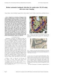
Between 1998 and 2000, N. Stevanovic and<br />
M. Hillebrand [6,116,117,114] reported a high speed<br />
Fig. 9. Architecture <strong>of</strong> the high speed <strong>CMOS</strong> <strong>image</strong>r.<br />
<strong>CMOS</strong> camera (see Fig. 9). It was able to acquire more<br />
than 1000 frame/s using a global shutter in each sensor cell.<br />
The integration time in synchronous exposure was variable<br />
between 1 ms and 150 instead <strong>of</strong> previous <strong>CMOS</strong><br />
implementations, which had around 500 frames/s at<br />
integration times ranging from 75 to 200 mm [42,113,112].<br />
So it <strong>of</strong>fered a compact, portable, and low power (320 mW)<br />
solution for high speed video systems and had a resolution<br />
<strong>of</strong> 256!256 pixels.<br />
DALSA Inc. Waterloo reported a VGA <strong>CMOS</strong> <strong>image</strong>r<br />
[115] in 2001, which can capture <strong>image</strong>s at 1600 frames per<br />
second (see Fig. 10). Furthermore, it has exposure control<br />
functionality, antiblooming capability and a non-rolling<br />
shutter architecture to implement snap-shot <strong>image</strong> capture<br />
mode.<br />
Also in 2001, S. Yoshimura, T. Sugiyama, K. Yonemoto<br />
and K. Ueda reported a 48 kframe/s <strong>CMOS</strong> Image sensor for<br />
Fig. 8. Photodiode-type shutter APS schematics.<br />
Fig. 10. Pixel <strong>of</strong> a DALSA VGA <strong>CMOS</strong> <strong>image</strong>r.
444<br />
M. Bigas et al. / Microelectronics Journal 37 (2006) 433–451<br />
Real-time 3D Sensing and Motion Detection [118]. It had an<br />
array <strong>of</strong> 192!124 pixels, depth resolution <strong>of</strong> 500 mm, fast<br />
motion detection and 12b digital <strong>image</strong> output resolution.<br />
E. Fossum and A. Krymski introduced first a 1280!720<br />
pixel at 60 fps (60 Mpixel/s), then reported a 1024!1024<br />
pixel at 500 fps (500 Mpixel/s). They continued enhancing<br />
their design, when in 2003 they presented [119] a high<br />
speed, 240 fps, 4.1 Mpixel(2352!1728) <strong>CMOS</strong> sensor (O<br />
800 Mpixels/s) with on-chip parallel 10-b analog-to-digital<br />
converters (ADCs) and power dissipation <strong>of</strong> less than<br />
700 mW. Besides this, in 2003, a High-responsivity 9-<br />
V/Lux-s, high speed 5000 fps at full 512!512 resolution<br />
<strong>CMOS</strong> sensor was manufactured [44]. The sensor was<br />
designed for a 0.35 mm process and consisted <strong>of</strong> a five<br />
transistor pixel to provide a true parallel shutter.<br />
3.4.3. High speed market<br />
High speed imaging systems are suitable for automotive<br />
applications such as occupancy detection, precrash sensing,<br />
collision avoidance, surveillance, crash test observation, or<br />
airbag control. For instance, a smart airbag solution based<br />
on a high speed camera system was designed by Fraunh<strong>of</strong>er<br />
Institute <strong>of</strong> Microelectronic Circuits and Systems [120]. The<br />
system continuously monitors the seats and quickly<br />
determines the occupancy status and passenger’s position<br />
and size before the airbag is blasted. Another application is<br />
smart <strong>image</strong> sensor for real-time. For instance Yosuke Oike<br />
reported in 2003 a smart <strong>image</strong> sensor for real-time and<br />
high-resolution 3D measurement [121]. It does not only<br />
have enough high frame rate for real-time 3D measurement,<br />
but also high pixel resolution owing to a small pixel circuit<br />
and high subpixel accuracy due to gravity center calculation<br />
using a light intensity pr<strong>of</strong>ile measurement trick. Finally, an<br />
application for high-speed video systems, for fast moving<br />
objects or for machinery vision is also suitable.<br />
3.5. Low noise <strong>sensors</strong><br />
<strong>CMOS</strong> Image <strong>sensors</strong> suffer from several noise sources.<br />
These set the fundamental limits on <strong>image</strong> sensor<br />
performance, especially under low illumination and in<br />
video applications. Therefore, it is important to have an<br />
overview <strong>of</strong> all <strong>of</strong> them [80]. The noise sources in <strong>CMOS</strong><br />
Imagers can be divided in Temporal Noise [81] and Fixed<br />
Pattern Noise (FPN) [43].<br />
In fact, FPN is one <strong>of</strong> the major <strong>CMOS</strong> <strong>image</strong>r’s<br />
disadvantages. Thus, a lot <strong>of</strong> research has been done in order<br />
to minimise FPN.<br />
Many researchers have designed FPN-reduction circuits.<br />
For instance, Correlated Double Sampling (CDS) is one <strong>of</strong><br />
the most suitable for suppressing FPN [50,76]. Fig. 11<br />
shows a typical schematic <strong>of</strong> a CDS circuit. CDS technique<br />
consists <strong>of</strong> taking two samples from a signal, which are<br />
closely spaced in time. Then, the first signal is substratcted<br />
from the second one, hence, removing the low-frequency<br />
noise. Sampling occurs twice: first after reset and last after<br />
Fig. 11. Schematic diagram <strong>of</strong> the correlated double sampling circuit. There<br />
is one such circuit for every column.<br />
integrating the signal charge. The subtraction removes the<br />
reset noise and dc <strong>of</strong>fset from the signal charge. The two<br />
values are then used as differential signals in further stages<br />
like programmable gain amplifiers (PGA) or ADC. Most <strong>of</strong><br />
them are placed below each column <strong>of</strong> pixels (see Fig. 12a).<br />
However, CDS reduces the fixed pattern noise to a large<br />
extent, a component <strong>of</strong> the FPN due to mismatch in the CDS<br />
circuits at each column introduces column-FPN, which<br />
should be also removed. For instance, K. Yonemoto and<br />
H. Sumi proposed [50] that FPN reduction should be<br />
performed in a CDS circuit (see Fig. 12b), in order to avoid<br />
this column-FPN caused by CDS circuits. On the other<br />
hand, although the dark current variation <strong>of</strong> photodiodes<br />
appears as FPN in the output signal <strong>of</strong> a <strong>CMOS</strong> <strong>image</strong><br />
sensor, which resembles FPN caused by threshold variation<br />
<strong>of</strong> transistors in pixel circuits, the dark current noise cannot<br />
be suppressed with CDS circuits. This is because the dark<br />
current does not appear in the reset level, but only in the<br />
signal level <strong>of</strong> the pixel signal. Therefore, the dark current<br />
<strong>of</strong> the photodiode itself should be reduced.<br />
One way <strong>of</strong> reducing the dark current is to employ a<br />
pinned photodiode [122]. Another method reported by<br />
K. Yonemoto and H. Sumi in 2000 is a pinned photodiode,<br />
in the form <strong>of</strong> hole accumulation diode (HAD) [50]. They<br />
achieved a reduction <strong>of</strong> the dark current to 150 pA/cm 2<br />
instead <strong>of</strong> 6 nA/cm 2 <strong>of</strong> a pn-photodiode. As a result, the dark
M. Bigas et al. / Microelectronics Journal 37 (2006) 433–451 445<br />
Fig. 12. (a) <strong>CMOS</strong> <strong>image</strong> sensor with column CDS circuit, (b) <strong>CMOS</strong> <strong>image</strong> sensor with proposed FPN-reduction scheme.<br />
current variation at the output <strong>of</strong> the <strong>CMOS</strong> <strong>image</strong> sensor<br />
was 0.19 mV and the period <strong>of</strong> readout operation was about<br />
20 ns at 30 frames/s. Two years later, K. Yonemoto and H.<br />
Sumi carried out [49] a numerical analysis <strong>of</strong> this <strong>CMOS</strong><br />
Image sensor with a simple FPN reduction technology. They<br />
showed that the low-input-voltage I–V converter with a<br />
current-mirror circuit improves the amplification factor and<br />
linearity <strong>of</strong> the pixel circuit. In a five-transistor pixel circuit,<br />
the threshold voltage <strong>of</strong> the X–Y addressing transistor<br />
affects the amplitude and the level <strong>of</strong> the readout pulse. An<br />
analysis <strong>of</strong> the mechanism <strong>of</strong> the X–Y addressing transistor<br />
showed the basic concept behind the selection <strong>of</strong> the<br />
threshold voltage. An L-shaped readout gate for a pinned<br />
photodiode was compared with a straight readout gate, and<br />
was proved to be adequate for rapid charge transfer.<br />
Another circuit to suppress FPN peak-to-peak to 0.15% <strong>of</strong><br />
saturation level is Delta-difference sampling (DDS) [123].<br />
On the other hand, B. Fowler [43] proposed a new APS,<br />
called Capacitive Transimpedance Amplifier (CTIA). CTIA<br />
APS that can achieve low FPN by using a divider circuit<br />
with switched capacitor voltage feedback. Besides this, the<br />
high gain and low read noise are advantages <strong>of</strong> using a<br />
CTIA as well (See Fig. 5h and g).<br />
Moreover, other readout methods can also <strong>of</strong>fer an<br />
improvement in order to suppress FPN. For instance, R&D<br />
Headquarters from Minolta Co. and Gazoh System Kaihatsu<br />
reported a <strong>CMOS</strong> APS with transversal readout architecture<br />
that eliminates the vertically striped FPN [73,75]. The possibility<br />
<strong>of</strong> high frame rate using a multiport structure was also<br />
demonstrated. In addition, the Photonics and Sensors Group<br />
<strong>of</strong> the Cambridge University suggested, in 2002 [74], a new<br />
readout circuit for a <strong>CMOS</strong> APS, which removes the FPN and<br />
reduces signal degradation while <strong>of</strong>fering an increase in<br />
readout speed compared to the conventional approach.<br />
As outlined before, CDS can not suppress the dark<br />
current noise, although it is a FPN’s source. Thus,<br />
decreasing the dark current to suppress FPN has been an<br />
aim. Dark current (<strong>of</strong>fset error) is the signal charge that the<br />
pixel collects in the absence <strong>of</strong> light divided by<br />
the integration time. Dark current is temperature-sensitive<br />
and typically normalised by area. Photobit Technology<br />
Corporation and Tokyo institute <strong>of</strong> Technology reported a<br />
low dark current stacked <strong>CMOS</strong> APS for charged particle<br />
detection [124,125]. A use <strong>of</strong> a p-MOSFET transistor for<br />
readout reduces the hot carrier effect; thereby the dark<br />
current within the low temperature region is greatly<br />
decreased. It also improves noise reading performance due<br />
to its lower flicker noise compared to n-MOSFETs’.<br />
Thanks to the improvement <strong>of</strong> the noise performance,<br />
<strong>CMOS</strong> Image Sensors for Low light level applications are<br />
possible [18]. In 2000, a CDS noise analysis <strong>of</strong> readout<br />
circuits used in <strong>CMOS</strong> APS for low light levels was carried<br />
out [17]. In 2001, different pixel architectures were studied<br />
in order to increase the sensitivity and reduce the spatial<br />
(FPN) and temporal noise [16]. This study demonstrates that<br />
the N-well photodiode is the best light sensor, either for its<br />
parasitic capacitance value, for its quantum efficiency, or for<br />
its dark current. However, the design rules required by this<br />
photodiode (a wide space must be kept between N well and<br />
MOS transistors) limit their use in <strong>CMOS</strong> <strong>image</strong>rs. On the<br />
other hand, a new pixel architecture was also introduced.<br />
This architecture reduces kTC or reset noise and FPN.<br />
Therefore, this architecture is ideal for applications<br />
requiring very high sensitivity and low noise, which is<br />
necessary for low light level sensing.<br />
Complete reset <strong>of</strong> the photodiode is needed in order to<br />
remove kTC or reset noise and decrease the lag effect. Note<br />
that the source <strong>of</strong> <strong>image</strong> lag in <strong>CMOS</strong> <strong>image</strong>rs is different<br />
from the source <strong>of</strong> <strong>image</strong> lag in CCDs. In CCDs, <strong>image</strong> lag<br />
is caused by incomplete charge transfer. This can be<br />
eliminated using a pinned photodiode. On the other hand,<br />
<strong>CMOS</strong> <strong>image</strong> lag is due to incomplete reset so, in 2001,<br />
H. Tian [81] reported a new reset method, which alleviates<br />
the lag without increasing the reset noise. The reset<br />
transistor gate is overdriven.<br />
Finally, <strong>CMOS</strong> APS still has readout-noise problems<br />
because <strong>of</strong> irregular gain from mismatched transistor<br />
thresholds.
446<br />
4. Applications<br />
M. Bigas et al. / Microelectronics Journal 37 (2006) 433–451<br />
4.4. Digital photography<br />
As highlighted before, improvement <strong>of</strong> <strong>CMOS</strong> <strong>image</strong><br />
<strong>sensors</strong> has opened up new application areas [45]. Therefore,<br />
<strong>CMOS</strong> <strong>image</strong>rs are very suitable for Space, Automotive,<br />
Medical, Digital photography and 3D applications.<br />
Furthermore, there are more specific applications such as<br />
portable devices [100,101,31], security, industrial vision<br />
[126,127], consumer electronics, imaging phones, astronomy,<br />
surveillance [128], robotics and machine vision,<br />
guidance and navigation (e.g., stereovision [129]), computer<br />
inputs, etc.<br />
4.1. Space applications<br />
<strong>CMOS</strong> Imagers are widely used in the space environment<br />
for a varied range <strong>of</strong> applications [130,131]. These<br />
applications include robotic and navigation cameras,<br />
<strong>image</strong>rs for astronomy and earth observation, star trackers<br />
[132], tracking <strong>sensors</strong> in satellite constellations, lander and<br />
rover <strong>image</strong>rs, X-ray satellite missions [133,134], etc.<br />
Moreover, <strong>CMOS</strong> <strong>image</strong>rs are known to be tolerant to<br />
radiation, although true radiation tolerance can only be<br />
obtained using specific methods. Thus, there is a huge<br />
interest in radiation-tolerant imaging systems [32–39,135,<br />
136]<br />
4.2. Automotive applications<br />
There are a lot <strong>of</strong> applications [137] in the automotive<br />
field like occupancy detection, airbag control, precrash<br />
sensing, collision avoidance, surveillance, crash test<br />
observation, etc. Another one is a smart airbag solution<br />
based on a high speed camera system [120]. This system<br />
continuously monitors the seats and quickly determines the<br />
occupancy status and passenger’s position and size before<br />
the airbag is blasted. Moreover, IR-vision systems for foggy<br />
and night driving conditions are also addressable.<br />
4.3. Medical applications<br />
Medical or Biomedical systems based on <strong>CMOS</strong> <strong>image</strong>rs<br />
have been successfully developed [138]. For instance,<br />
Microelectronic components for a retina-implant system<br />
that will provide visual sensations to patients suffering from<br />
photoreceptor degeneration was reported by M. Schwarz in<br />
1999 [139]. On the other hand, the digitisation <strong>of</strong> medical<br />
<strong>image</strong>s, especially in radiology, has been another demand in<br />
recent years. Ho Kyung Kim proposed an X-ray imaging<br />
system with large FOV (field-<strong>of</strong>-view) using <strong>CMOS</strong> <strong>image</strong><br />
<strong>sensors</strong> [140]. S. Wook Lee reported a 3-D Xray<br />
microtomographic system [141] in 2001. It makes possible<br />
to see the internal structure <strong>of</strong> small objects in a nondestructive<br />
way. Finally, P. Lechner developed an APS for<br />
X-ray imaging Spectroscopy in 2001 [142].<br />
A <strong>CMOS</strong> <strong>image</strong> sensor integrating the sensor itself<br />
and the digital control functions on a single chip was<br />
reported [1]. This demonstrates the viability <strong>of</strong> producing a<br />
camera-on-a-chip suitable for commercial and scientific<br />
applications [143,144]. Besides, cameras with nearly noisefree<br />
pictures [145] and low power consumption have been<br />
developed. In 1998, Toshiba Corp. reported a 3.7!3.7 mm 2<br />
square pixel <strong>CMOS</strong> <strong>image</strong> sensor [146] for Digital Still<br />
Camera applications with high performance.<br />
4.4.1. 3D range imaging applications<br />
3D range imaging systems are more and more required<br />
due to the fact that 3D <strong>image</strong>s acquisition is important in<br />
various sectors such as home, public and industrial domains.<br />
Furthermore, improvements in speed and resolution<br />
performance have opened up the possibility to obtain real<br />
time systems.3D range imaging system, also called 3D<br />
digitiser or Range finder, is a system capable to acquire<br />
range or depth information. These devices grab ‘range<br />
<strong>image</strong>s’ or ‘ <strong>image</strong>s’, which are dense arrays <strong>of</strong> values<br />
related to the distance <strong>of</strong> the scene to a known point or plane<br />
[147]. Currently, there are some special 3D measurement<br />
methods available for scene reconstruction. These techniques<br />
rely on triangulation (see Fig. 13), time-<strong>of</strong>-flight<br />
(TOF) measurements or interferometry, etc. [148] The range<br />
<strong>of</strong> possible applications is wide. For instance, obtaining 3D<br />
Models from Range Scans [149], Space monitoring and<br />
surveillance [118], safety and security [148,120], Real time<br />
Sensing and Motion detection [118], Inspection [150], 3D<br />
X-ray imaging [141], Robot vision [151], etc.<br />
4.5. Other applications<br />
There are more suitable applications, such as portable<br />
applications [100,101,31], security, industrial vision (e.g.,<br />
Imager with focal plane edge detection [127]), consumer<br />
electronics, surveillance devices [128], Smart vision system<br />
on-a-chip [143,144,129,152], Robotics and machine vision,<br />
Fig. 13. 3D measurement system based on triangulation.
M. Bigas et al. / Microelectronics Journal 37 (2006) 433–451 447<br />
guidance and navigation (e.g., stereovision [129]), video<br />
phones, computer inputs, for charged particle imaging [124,<br />
125] such as ion and electron imaging, IR-vision applications,<br />
low light level applications [16–18], electrostatic<br />
sensing, instrumentation, imaging phones, astronomy and<br />
low-end pr<strong>of</strong>essional cameras.<br />
5. Conclusions<br />
A review <strong>of</strong> the most important advances in the field <strong>of</strong><br />
<strong>CMOS</strong> <strong>image</strong> <strong>sensors</strong> has been carried out. These<br />
advantages have been mainly focused on fields such as<br />
sensitivity, low noise, low power consumption, low voltage<br />
operation, high-speed imaging and good dynamic range.<br />
This paper demonstrates that <strong>CMOS</strong> <strong>image</strong>rs are competitive<br />
with CCDs in many application areas, such as security,<br />
consumer digital cameras, automotive, computer video,<br />
imaging phones, etc. <strong>CMOS</strong> <strong>image</strong>rs will replace CCD<br />
devices in some cases, because <strong>of</strong> its low cost, low power<br />
consumption, integration capability, etc. Nevertheless, CCD<br />
technology will continue as predominant in high performance<br />
systems, such as medical imaging, astronomy, low-end<br />
pr<strong>of</strong>essional cameras, etc. because <strong>of</strong> its better <strong>image</strong><br />
quality. To sum up, State-<strong>of</strong>-the-art <strong>of</strong> <strong>CMOS</strong> <strong>image</strong> <strong>sensors</strong><br />
has been provided.<br />
References<br />
[1] E. Fossum, Cmos <strong>image</strong> <strong>sensors</strong>: electronic camera-on-a-chip, IEEE<br />
transactions on electron devices 44 (10) (1997).<br />
[2] S. Kempainen, Cmos <strong>image</strong> <strong>sensors</strong>:eclipsing ccds in visual<br />
information?, EDN 42 (21) (1997) 101–102 [See also pp. 105–6,<br />
108, 110].<br />
[3] C.-H. Chen, H.-J. Tsai, K.-S. Huang, and H.-T. Liu, Study for cross<br />
contamination between cmos <strong>image</strong> sensor and ic product, in 2001<br />
IEEE/SEMI Advanced Semiconductor Manufacturing Conference,<br />
2001, pp. 121–123.<br />
[4] H.-S.P. Wong, Cmos <strong>image</strong> <strong>sensors</strong>-recent advances and device<br />
scaling considerations, in International Electron Devices Meeting<br />
1997. IEDM, 1997, pp. 201–204.<br />
[5] A. Theuwissen, Ccd or cmos <strong>image</strong> <strong>sensors</strong> for consumer digital still<br />
photography? in International Symposium on VLSI Technology,<br />
Systems, and Applications, 2001. Proceedings <strong>of</strong> Technical Papers,<br />
2001, pp. 168–171.<br />
[6] M. Hillebrand, N. Stevanovic, B. Hosticka, J. Conde, A. Teuner, and<br />
M. Schwarz, High speed camera system using a cmos <strong>image</strong> sensor,<br />
in Proceedings <strong>of</strong> the IEEE Intelligent Vehicles Symposium 2000.<br />
2000, pp. 656–61.<br />
[7] W.S. Boyle, G. Smith, Charge-coupled semiconductor devices, Bell<br />
System Techenics <strong>of</strong> Journal 49 (1970) 587–593.<br />
[8] J. Zarnowski, M. Pace, M. Joyner, Active-pixel cmos sensor improve<br />
their <strong>image</strong>, Laser Focus World. PennWell Plublishing 35 (7) (1999)<br />
111–114.<br />
[9] I. Shcherback, O. Yadid-Pecht, Photoresponse analysis and pixel<br />
shape optimization for cmos active pixel <strong>sensors</strong>, IEEE Transactions<br />
on Electron Devices 50 (2003) 12–18.<br />
[10] W. Zhang, M. Chan, H. Wang, and P. Ko, Building hybrid active<br />
pixels for cmos <strong>image</strong>r on soi substrate, in SOI Conference.<br />
Proceedings. IEEE International, 1999, pp. 102–103.<br />
[11] Y. Malinovich, Ultra-high resolution cmos <strong>image</strong> <strong>sensors</strong>, Electronic<br />
Product Design. IML Techpress 20 (7) (1999) 19–20.<br />
[12] Z. Zhou, B. Pain, and E. Fossum, A cmos <strong>image</strong>r with on-chip<br />
variable resolution for light-adaptive imaging, in IEEE International<br />
Solid-State Circuits Conference. 45th ISSCC, Feb. 1998,<br />
pp. 174–175, 433.<br />
[13] J. Coulombe, M. Sawan, and C. Wang, “Variable resolution cmos<br />
current mode active pixel sensor, in IEEE International Symposium<br />
on Circuits and Systems. Proceedings. ISCAS 2000 Geneva., vol. 2,<br />
2000, pp. 293–296.<br />
[14] Y. Audet and G. Chapman, Design <strong>of</strong> a self-correcting active pixel<br />
sensor, in IEEE International Symposium on Defect and Fault<br />
Tolerance in VLSI Systems, 2001. Proceedings., 2001, pp. 18–26.<br />
[15] I. Koren, G. Chapman, and Z. Koren, A self-correcting active pixel<br />
camera, in IEEE International Symposium on Defect and Fault<br />
Tolerance in VLSI Systems, 2000. Proceedings., 2000, pp. 56–64.<br />
[16] J. Goy, B. Courtois, J. Karam, F. Pressecq, Design <strong>of</strong> an aps<br />
cmos <strong>image</strong> sensor for low light level applications using standard<br />
cmos technology Analog Integrated Circuits and Signal Processing,<br />
vol. 29, Kluwer Academic Publishers, Dordrecht, 2001. pp.<br />
95–104.<br />
[17] Y. Degerli, F. Lavernhe, P. Magnan, J. Farre, Analysis and reduction<br />
<strong>of</strong> signal readout circuitry temporal noise in cmos <strong>image</strong> <strong>sensors</strong> for<br />
low-light levels, IEEE Transactions on Electron Devices 47 (5)<br />
(2000) 949–962.<br />
[18] D. Cr<strong>of</strong>t, Cmos <strong>image</strong> <strong>sensors</strong> compete for low-light tasks, Laser<br />
Focus World. PennWell Publishing 35 (1) (1999) 135–136 [See<br />
alspo pp. 138–40].<br />
[19] E. Fossum and A. Krymski, High speed cmos imaging. in Electronic-<br />
Enhanced Optics, Optical Sensing in Semiconductor Manufacturing,<br />
Electro-Optics in Space, Broadband Optical Networks. Digest <strong>of</strong> the<br />
LEOS Summer Topical Meetings, July 2000, pp. I3–I4.<br />
[20] T. Lule, S. Benthien, H. Keller, F. Mutze, P. Rieve, K. Seibel,<br />
M. Sommer, M. Bohm, Sensitivity <strong>of</strong> cmos based <strong>image</strong>rs and<br />
scaling perspectives, IEEE transactions on electron devices 47<br />
(2000) 2110–2122.<br />
[21] T. Lule, M. Wagner, M. Verhoeven, H. Keller, M. Bohm, 100000-<br />
pixel, 120-db <strong>image</strong>r in tfa technology, IEEE Journal <strong>of</strong> Solid-State<br />
Circuits 35 (2000) 732–739.<br />
[22] T. Lule, H. Keller, M. Wagner, and M. Bohm,100.000 pixel 120 db<br />
<strong>image</strong>r in tfa-technology, in Symposium on VLSI Circuits, 1999.<br />
Digest <strong>of</strong> Technical Papers, June 1999, pp. 133–136.<br />
[23] T. Lule, B. Schneider, M. Bohm, Design and fabrication <strong>of</strong> a highdynamicrange<br />
<strong>image</strong> sensor in tfa technology, IEEE Journal <strong>of</strong><br />
Solid-State Circuits 34 (1999) 704–711.<br />
[24] B. Schneider, H. Fischer, S. Benthien, H. Keller, T. Lule, P. Rieve,<br />
M. Sommer, J. Schulte, and M. Bohm, Tfa <strong>image</strong> <strong>sensors</strong>: from the<br />
one transistor cell to a locally adaptive high dynamic range sensor, in<br />
Electron Devices Meeting, 1997. Technical Digest., International,<br />
1997, pp. 209–212.<br />
[25] C. Xu, W.-H. Ki, M. Chan, A low-voltage cmos complementary<br />
active pixel sensor (caps) fabricated using a 0.25 (m cmos<br />
technology, IEEE Electron Device Letters 23 (2002) 398–400.<br />
[26] C. Xu, W. Zhang, W.-H. Ki, and M. Chan, A highly integrated cmos<br />
<strong>image</strong> sensor architecture for low voltage applications with deep<br />
submicron process, in IEEE International Symposium on Circuits<br />
and Systems. ISCAS 2002., vol. 3, 2002, pp. 699 –702.<br />
[27] C. Shen, C. Xu, Weiquan, W.R. Huang, and M. Chan, Low voltage<br />
cmos active pixel sensor design methodology with device scaling<br />
considerations, in IEEE Hong Kong Electron Devices Meeting, June<br />
2001, pp. 21–24.<br />
[28] C. Xu, W. Zhang, and M. Chan, A 1.0 v vdd cmos active pixel <strong>image</strong><br />
sensor with complementary pixel architecture fabricated with a<br />
0.25 m cmos process, in IEEE International Solid-State Circuits<br />
Conference. ISSCC, vol. 1, 2002, pp. 44–443.
448<br />
M. Bigas et al. / Microelectronics Journal 37 (2006) 433–451<br />
[29] -, A 1.0 vdd cmos active pixel <strong>image</strong> sensor with complementary<br />
pixel architecture fabricated with a 0.25 m cmos process, in IEEE<br />
International Solid-State Circuits Conference. ISSCC, vol. 2, 2002,<br />
pp. 28–385.<br />
[30] C. Xu, W. Zhang, W.-H. Ki, M. Chan, A 1.0-v vdd cmos active-pixel<br />
sensor with complementary pixel architecture and pulsewidth<br />
modulation fabricated with a 0.25 (m cmos process, IEEE Journal<br />
<strong>of</strong> Solid-State Circuits 37 (2002) 1853–1859.<br />
[31] C. Xu and M. Chan, The approach to rail-to-rail cmos active pixel<br />
sensor for portable applications, in Proceedings <strong>of</strong> IEEE Region 10<br />
International Conference on Electrical and Electronic Technology.<br />
TENCON, vol. 2, 2001, pp. 834–837.<br />
[32] E.-S. Eid, S. Ay, and E. Fossum, Design <strong>of</strong> radiation tolerant cmos<br />
aps system-on-a chip <strong>image</strong> <strong>sensors</strong> in Aerospace Conference<br />
Proceedings, vol. 4, 2002, pp. 2005–2011.<br />
[33] E.-S. Eid, T. Chan, E. Fossum, R. Tsai, R. Spagnuolo, and J. Deily,<br />
Design <strong>of</strong> radiation hard cmos aps <strong>image</strong> <strong>sensors</strong> in 0.35 m cmos<br />
standard process,in Proceedings <strong>of</strong> the SPIE—The International<br />
Society for Optical Engineering, vol. 4306, 2002, pp. 50-9.<br />
[34] J. Bogaerts, B. Dierickx, R Mertens, Random telegraph signals in a<br />
radiationhardened cmos active pixel sensor, IEEE Transactions on<br />
Nuclear Science 49 (2002) 249–257.<br />
[35] J. Bogaerts, B. Dierickx, G. Meynants, D. Uwaerts, Total dose and<br />
displacement damage effects in a radiation-hardened cmos aps, IEEE<br />
Transactions on Electron Device 50 (84) (2003) 90.<br />
[36] J. Bogaerts, B. Dierickx, R. Mertens, Enhanced dark current<br />
generation in proton-irradiated cmos active pixel <strong>sensors</strong>, IEEE<br />
Transactions on nuclear science 49 (2002) 1513–1521.<br />
[37] M. Cohen and J. David, Radiation effects on active pixel <strong>sensors</strong>, in<br />
Fifth European Conference on Radiation and Its Effects on<br />
Components and Systems. ADECS 99., 1999, pp. 450–456.<br />
[38] -, “Radiation-induced dark current in cmos active pixel <strong>sensors</strong>,”<br />
IEEE Transactions on Nuclear Science, vol. 47, pp. 2485–2491,<br />
2000.<br />
[39] G. Hopkinson, Radiation effects in a cmos active pixel sensor, IEEE<br />
Transactions on Nuclear Science 47 (2000) 2480–2485.<br />
[40] C.-C. Wang and C. Sodini,The effect <strong>of</strong> hot carriers on the operation<br />
<strong>of</strong> cmos active pixel <strong>sensors</strong>, in International Electron Devices<br />
Meeting, 2001. IEDM Technical Digest., 2001, pp. 24.5.1–.5.4.<br />
[41] C. Seibold. (2002) Comparison <strong>of</strong> cmos and ccd <strong>image</strong> sensor<br />
technologies. [Online]. Available: http://eng.oregonstate.edu/wmillerst/ece44x.<br />
[42] A. Krymski, D. Blerkom, A. Andersson, N. Bock, B. Mansoorian,<br />
and E.R. Fossum,A high speed, 500 frame/s, 1024x1024 cmos active<br />
pixel sensor, in IEEE Symposium on VLSI Circuits Digest <strong>of</strong><br />
Technical Papers, 1999, pp. 137 -138.<br />
[43] B. Fowler, J. Balicki, D. How, and M. Godfrey, Low fpn high gain<br />
capacitive transimpedance amplifier for low noise cmos <strong>image</strong><br />
<strong>sensors</strong>, in Proceedings <strong>of</strong> the SPIE. The International Society for<br />
Optical Engineering, vol. 4306, 2001, pp. 68–77.<br />
[44] A.I. Krymski, N. Tu, A 9-v/lux-s 5000-frame/s 512!512 cmos<br />
sensor, IEEE Transactions on electron devices 50 (1) (2003)<br />
136–143.<br />
[45] C.H. Small, “Lower costs open new application areas for cmos<br />
<strong>image</strong> <strong>sensors</strong>, Computer Design, International Edition, PennWell<br />
Publishing 37 (4) (1998) 37–40 [See also pp. 42–43].<br />
[46] H.-S. Wong;, Technology and device scaling considerations for<br />
cmos <strong>image</strong>rs, IEEE Transactions on Electron Devices 43 (1996)<br />
2131–2142.<br />
[47] S. Mendis, S. Kemeny, R. Gee, B. Pain, C. Staller, Q. Kim,<br />
E. Fossum, Cmos active pixel <strong>image</strong> sensor for highly integrated<br />
imaging systems, IEEE Journal <strong>of</strong> Solid-State Circuits 32 (1997)<br />
187–197.<br />
[48] Y. Muramatsu, S. Kurosawa, M. Furumiya, H. Ohkubo,<br />
Y. Nakashiba, A signalprocessing cmos <strong>image</strong> sensor using a simple<br />
analog operation, IEEE Journal <strong>of</strong> Solid-State Circuits 38 (2003)<br />
101–106.<br />
[49] K Yonemoto, H Sumi, A numerical analysis <strong>of</strong> a cmos <strong>image</strong> sensor<br />
with a simple fixed-pattern-noise-reduction technology, IEEE<br />
Transactions on Electron Devices 49 (2002) 746–753.<br />
[50] A cmos <strong>image</strong> sensor with a simple fixed-pattern-noise-reduction<br />
technology and a hole accumulation diode, IEEE Journal <strong>of</strong> Solid-<br />
State Circuits, vol. 35, pp. 2038–43, 2000.<br />
[51] J.-S. Ho, M.-C. Chiang, H.-M. Cheng, T.-P. Lin, and M.-J. Kao, A<br />
new design for a 1280!1024 digital cmos <strong>image</strong> sensor with<br />
enhanced sensitivity, dynamic range and fpn, in 1999 International<br />
Symposium on VLSI Technology, Systems, and Applications., 1999,<br />
pp. 235–238.<br />
[52] R. Nair and K. Raj, Signal processing in cmos <strong>image</strong> <strong>sensors</strong>, in<br />
IEEE Workshop on Signal Processing Systems. SIPS 2000, 2000, pp.<br />
801–810.<br />
[53] B. Sekerkiran, U. Cilingiroglu, A cmos k-winners-take-all circuit<br />
with o(n) complexity, IEEE Transactions on Circuits and Systems,<br />
II, Analog and Digital Signal Processing 46 (1) (1999) 1–5.<br />
[54] A. Demosthenous, S. Smedley, J. Taylor, A cmos analog winnertake-all<br />
network for large-scale applications, IEEE Transactions on<br />
Circuits and Systems I: Fundamental Theory and Applications 45 (3)<br />
(1998) 300–304.<br />
[55] J.-C. Yen, J.-I. Guo, H.-C. Chen, A new k-winners-take-all neural<br />
network and its array architecture, IEEE Transactions on Neural<br />
Networks 9 (5) (1998) 901–912.<br />
[56] N. Donckers, C. Dualibe, and M. Verleysen. (1999) Design <strong>of</strong><br />
complementary low-power cmos architectures for looser-take-all<br />
and winner-take-all. [Online]. Available: citeseer.nj.nec.com/donckers99design.html.<br />
[57] D.Y. Aksin, A high-precision high-resolution wta-max circuit <strong>of</strong> o(n)<br />
complexity, IEEE Transactions on Circuits and Systems 49 (1)<br />
(2002) 48–53.<br />
[58] G. Indiveri, P. Oswald, and J. Kramer, An adaptive visual tracking<br />
sensor with a hysteretic winner-take-all network, in IEEE<br />
International Symposium on Circuits and Systems. ISCAS 2002,<br />
vol. 2, 2002, pp. II–324 –II–327.<br />
[59] F. Blais, M. Lecavalier, and J. Bisson, Real-time processing and<br />
validation <strong>of</strong> optical ranging in a cluttered enviroment, in The 7th<br />
International Conference on Signal Processing Applications &<br />
Technology. ICSPAT’96, Oct. 1996.<br />
[60] Z. Zhang and V. Prinet, A rogh-to-fine satellite <strong>image</strong> registration<br />
method with subpixel accuracy, in International Conference on<br />
Image Processing, vol. 3, 2002, pp. III–385 –III–388.<br />
[61] L. Gonzo, M. Gottardi, F. Comper, A. Simoni, J.-A. Beraldin, F.<br />
Blais, M. Rioux, and J. Domey. Smart <strong>sensors</strong> for 3d digitization.<br />
[Online]. Available: http://www.vit.iit.nrc.ca/References/NRC-<br />
44934.pdf.<br />
[62] F. Eugenio, F. Marques, and J. Marcello, Pixel and sub-pixel<br />
accuracy in satellite <strong>image</strong> georeferencing using an automatic<br />
contour matching approach, in International Conference on Image<br />
Processing, vol. 1, 2001, pp. 822–825.<br />
[63] H. Kwon, S.Z. Der, and N.M. Nasrabadi. (2002) Subpixel target<br />
detection for hyperspectral <strong>image</strong>s using ica-based feature extraction.<br />
[Online]. Available: http://www.asc2002.com/manuscripts/J/<br />
JO-03.PDF.<br />
[64] S.S. Abeysekera, An efficient hilbert transform interpolation<br />
algorithm for peak position estimation, in Proceedings <strong>of</strong> the 11th<br />
IEEE Signal Processing Workshop on Statistical Signal Processing,<br />
2001, pp. 417–420.<br />
[65] J. Xu, Z.P. Fang, A.A. Malcolm, H. Wang, “Camera calibration<br />
for 3-d measurement with micron level accuracy,” in 5th (2001)<br />
2001.<br />
[66] P.C. Yu, S.J. Decaer, H.-S. Lee, C.G. Sodini, J. John, L. Wyatt, Cmos<br />
resistive fuses for <strong>image</strong> smoothing and segmentation, IEEE Journal<br />
<strong>of</strong> Solid-State Circuits 27 (4) (1992) 545.<br />
[67] S.-B. Park, A. Teuner, and B. Hosticaka, A motion detection system<br />
based on a cmos photo sensor array, in International Conference on<br />
Image Processing, 1998.
M. Bigas et al. / Microelectronics Journal 37 (2006) 433–451 449<br />
[68] S.-M. Sohn, M.G. Kim, S. Kim;, “A cmos <strong>image</strong> sensor (cis) with<br />
low power motion detection for security camera applications,” in<br />
IEEE International Conference on Consumer Electronics, ICCE.<br />
2003, June 2003, p. 250 (2003) 251.<br />
[69] Y. Muramatsu, S. Kurosawa, M. Furumiya, H. Ohkubo,<br />
Y. Nakashiba, A signal-processing cmos <strong>image</strong> sensor using a<br />
simple analog operation, IEEE Journal <strong>of</strong> Solid-State Circuits 38 (1)<br />
(2003) 101–106.<br />
[70] S. Kemeny, B. Pain, L. Matthies, E. Fossum, Multiresolution <strong>image</strong><br />
sensor, IEEE Transactions on Circuits and Systems for Video<br />
Technology 7 (1997) 575–583.<br />
[71] S. Kawahito, Y. Tadokoro, A. Matsuzawa, “Cmos <strong>image</strong> <strong>sensors</strong><br />
with video compression,” in Proceedings <strong>of</strong> the ASP-DAC ’98. Asia<br />
and South Pacific Design Automation Conference., Feb., p. 595<br />
(1998) 600.<br />
[72] Y.-C. Shih and C.-Y. Wu, The design <strong>of</strong> high-performance 128!<br />
128 cmos <strong>image</strong> <strong>sensors</strong> using new current-readout techniques, in<br />
IEEE International Symposium on Circuits and Systems. ISCAS ’99,<br />
vol. 5, May 1999, pp. 168–171.<br />
[73] S. Miyatake, M. Miyamoto, K. Ishida, T. Morimoto, Y. Masaki,<br />
H. Tanabe, Transveral-readout architecture for cmos active pixel<br />
<strong>image</strong> <strong>sensors</strong>, IEEE Transactions on Electron Devices 50 (2003)<br />
121–129.<br />
[74] T. Kwok, J.J. Zhong, T. Wilkinson, W.A. Crossland, Readout circuit<br />
for cmos active pixel <strong>image</strong> sensor, IEEE Electronics Letters 38<br />
(2002) 317–318.<br />
[75] S. Miyatake, K. Ishida, T. Morimoto, Y. Masaki, and H. Tanabe,<br />
Transversal-readout cmos active pixel <strong>image</strong> sensor, in Proceedings<br />
<strong>of</strong> the SPIE - The International Society for Optical Engineering, vol.<br />
4306, 2001, pp. 128–136.<br />
[76] Y. Degerli, F. Lavernhe, P. Magnan, P.J. Farre, Column readout<br />
circuit with global charge amplifier for cmos aps <strong>image</strong>rs, IEEE<br />
Electronics letters 36 (17) (2000) 1457–1459.<br />
[77] T. Watabe, M. Goto, H. Ohtake, H. Maruyama, M. Abe,<br />
K. Tanioka, N. Egami, New signal readout method for ultrahighsensitivity<br />
cmos <strong>image</strong> sensor, IEEE Transactions on Electron<br />
Devices 50 (2003) 63–69.<br />
[78] T. Watabe, M. Goto, H. Ohtake, H. Maruyama, and K. Tanioka, A<br />
new readout circuit for an ultra high sensitivity cmos <strong>image</strong> sensor,”<br />
in International Conference on Consumer Electronics. ICCE. 2002,<br />
2002, pp. 42–43.<br />
[79] C.-C. Hsieh, C.-Y. Wu, F.-W. Jih, T.-P. Sun, Focal-plane-arrays and<br />
cmos readout techniques <strong>of</strong> infrared imaging systems, IEEE<br />
Transactions on Circuits and Systems for Video Technology 7<br />
(1997) 594–605.<br />
[80] HPComponentsGroup. (1998) Noise sources in cmos <strong>image</strong> <strong>sensors</strong>.<br />
[Online]. Available: http://www.stw.tuilmenau.de/wff/beruf_cc/cmos/cmos_noise.pdf.<br />
[81] H. Tian, B. Fowler, A.E. Gamal, Analysis <strong>of</strong> temporal noise in cmos<br />
photodiode active pixel sensor, IEEE Journal <strong>of</strong> Solid-State Circuits<br />
36 (1) (2001) 92–101.<br />
[82] O. Schrey, J. Huppertz, G. Filimonovic, A. Bussmann,<br />
W. Brockherde, B. Hosticka, A 1 k!1 k high dynamic range cmos<br />
<strong>image</strong> sensor with on-chip programmable region-<strong>of</strong>-interest readout,<br />
IEEE Journal <strong>of</strong> Solid-State Circuits 37 (2002) 911–915.<br />
[83] M. Schanz, C. Nitta, A. Bussmann, B.J. Hosticka, R.K Wertheimer,<br />
A high-dynamic-range cmos <strong>image</strong> sensor for automotive applications,<br />
IEEE Journal <strong>of</strong> Solid-State Circuits 35 (2000) 932–938.<br />
[84] M. Loose, K. Meier, and J. Schemmel, Cmos <strong>image</strong> sensor with<br />
logarithmic response and self calibrating fixed pattern noise<br />
correction, in Proceedings <strong>of</strong> the SPIE - The International Society<br />
for Optical Engineering, vol. 3410, 1998, pp. 117–27.<br />
[85] R. Hauschild, M. Hillebrand, B.J. Hosticka, J. Huppertz, T. Kneip,<br />
and M. Schwarz, A cmos <strong>image</strong> sensor with local brightness<br />
adaptation and high intrascene dynamic range, in Proceedings <strong>of</strong> the<br />
24th European Solid-State Circuits Conference. ESSCIRC ’98,<br />
1998, pp. 308–11.<br />
[86] S. Kavadias, B. Dierickx, D. Scheffer, A. Alaerts, D. Uwaerts,<br />
J. Bogaerts, A logarithmic response cmos <strong>image</strong> sensor with onchip<br />
calibration, IEEE Journal <strong>of</strong> Solid-State Circuits 35 (2000)<br />
1146–1152.<br />
[87] S.-F. Chen, Y.-J. Juang, S.-Y. Huang, and Y.-C. King, Logarithmic<br />
cmos <strong>image</strong> sensor through multi-resolution analog-to-digital<br />
conversion, in International Symposium on VLSI Technology,<br />
Systems, and Applications, 2003, pp. 227–230.<br />
[88] J. Doge, G. Schonfelder, G.T. Streil, A. Konig, An hdr cmos <strong>image</strong><br />
sensor with spiking pixels, pixel-level adc, and linear characteristics,<br />
Germany IEEE Transactions on Circuits and Systems II: Analog and<br />
Digital Signal Processing 49 (2002) 155–158.<br />
[89] N. Tu, R. Hornsey, and S.G. Ingram, Cmos active pixel <strong>image</strong> sensor<br />
with combined linear and logarithmic mode operation, in IEEE<br />
Canadian Conference on Electrical and Computer Engineering, vol.<br />
2, May 1998, pp. 754–757.<br />
[90] W. Yang and A. Chiang, A full fill-factor ccd <strong>image</strong>r with integrated<br />
signal processors, in IEEE International Solid-State Circuits<br />
Conference, 37th ISSCC., 1990, pp. 218–219.<br />
[91] R. Reich, D. O’Mara, D. Young, A. Loomis, D. Rathman, D. Craig,<br />
S. Watson, M. Ulibarri, and B. Kosicki, High-fill-factor, burst-framerate<br />
charge-coulped device, in International Electron Devices<br />
Meeting, 2001. IEDM Technical Digest, Dec. 2001, pp. 24.6.1–<br />
24.6.4.<br />
[92] S. Chamberlain, Photosensitivity and scanning <strong>of</strong> silicon <strong>image</strong><br />
detector arrays, IEEE Journal <strong>of</strong> Solid-State Circuits 4 (1969)<br />
333–342.<br />
[93] Y.-T. Fan, C.-S. Peng, and C.-Y. Chu, Advanced microlens and color<br />
filter process technology for the high-efficiency cmos and ccd <strong>image</strong><br />
<strong>sensors</strong>, in Proceedings <strong>of</strong> the SPIE - The International Society for<br />
Optical Engineering, vol. 4115, 2000, pp. 263–74.<br />
[94] A. Bermak, A. Bouzerdoum, and K. Eshraghian, A high fill-factor<br />
native logarithmic pixel: simulation, design and layout optimization.<br />
in The 2000 IEEE International Symposium on Circuits and<br />
Systems. ISCAS 2000 Geneva, vol. 5, 2000, pp. 293–296.<br />
[95] P. Hasler, A. Bandyopadhyay, and P. Smith, A matrix transform<br />
<strong>image</strong>r allowing high-fill factor, in IEEE International Symposium<br />
on Circuits and Systems. ISCAS 2002., vol. 3, 2002, pp. 337–340.<br />
[96] H.-C. Chang and Y.-C. King, Tunable injection current compensation<br />
architecture for high fill-factor self-buffered active pixel<br />
sensor, in IEEE Asia-Pacific Conference on ASIC, 2002., 2002, pp.<br />
101–104.<br />
[97] B. Dierickx, G. Meynants, and D. Scheffer, Near 100% fill factor<br />
cmos active pixels, in IEEE CCD and AIS workshop, 1997.<br />
[98] G. Meynants, B. Dierickx, and D. Scheffer, Cmos active pixel <strong>image</strong><br />
sensor with ccd performance,” in Proceedings <strong>of</strong> the SPIE - The<br />
International Society for Optical Engineering, vol. 3410, 1998, pp.<br />
68–76.<br />
[99] M. Furumiya, H. Ohkubo, Y. Muramatsu, S. Kurosawa, F. Okamoto,<br />
Y. Fujimoto, Y. Nakashiba, High-sensitivity and no-crosstalk pixel<br />
technology for embedded cmos <strong>image</strong> sensor, IEEE Transactions on<br />
Electron Devices 48 (2001) 2221–2227.<br />
[100] K. Yoon, C. Kim, B. Lee, D. Lee, Single-chip cmos <strong>image</strong> sensor for<br />
mobile applications, IEEE Journal <strong>of</strong> Solid-State Circuits 37 (2002)<br />
1839–1845.<br />
[101] K.-B. Cho, A. Krymski, and E. Fossum, A 1.2 v micropower cmos<br />
active pixel <strong>image</strong> sensor for portable applications, in IEEE<br />
International Solid-State Circuits Conference, ISSCC., 2000, pp.<br />
114-115.<br />
[102] E. Fossum, Low power camera-on-a-chip. using cmos active pixel<br />
sensor technology, in IEEE Symposium on Low Power Electronics,<br />
1995, pp. 74–77.<br />
[103] B. Pain, G. Yang, B. Olson, T. Shaw, M. Ortiz, J. Heynssens,<br />
C. Wrigley, and C. Ho, A low-power digital camera-on-a-chip<br />
implemented in cmos active pixel approach, in Twelfth International<br />
Conference On VLSI Design, Jan. 1999, pp. 26–31.
450<br />
M. Bigas et al. / Microelectronics Journal 37 (2006) 433–451<br />
[104] H.P. Wong, R.T. Chang, E. Crabbe, P.D. Agnello, Cmos active pixel<br />
<strong>image</strong> <strong>sensors</strong> fabricated using a 1.8-v, 0.25 m cmos technology,<br />
IEEE Transactions on Electron Devices 45 (1998) 889–894.<br />
[105] B. Mansoorian, H.-Y. Yee, S. Huang, and E. Fossum, A 250mw, 60<br />
frames/s 1280!720 pixel 9 b cmos digital <strong>image</strong> sensor, in IEEE<br />
International Solid-State Circuits Conference. ISSCC, 1999, pp.<br />
312–13.<br />
[106] K.-B. Cho, A. Krymski, and E.R. Fossum, A 1.2 v micropower cmos<br />
active pixel <strong>image</strong> sensor for portable applications, in 2000 IEEE<br />
International Solid-State Circuits Conference, 2000, pp. 114–15.<br />
[107] C. Xu, W. Zhang, M. Chan, A low voltage hybrid bulk/soi cmos<br />
active pixel <strong>image</strong> sensor, IEEE Electron Device Letters 22 (2001)<br />
248–250.<br />
[108] J. Ohta, H. Sakata, T. Tokuda, and M. Nunoshita, Low-voltage<br />
operation <strong>of</strong> a cmos <strong>image</strong> sensor based on pulse frequency<br />
modulation, in Proceedings <strong>of</strong> the SPIE - The International Society<br />
for Optical Engineering, vol. 4306, 2001, pp. 319–26.<br />
[109] K.-B. Cho, A.I. Krymski, E.R. Fossum, A 1.5-v 550(w 176!144<br />
autonomous cmos active pixel <strong>image</strong> sensor, IEEE Transactions on<br />
Electron Devices 50 (2003) 96–105.<br />
[110] E.R.F. Kwang-Bo Cho, Alexander I. Krymski, A 3-pin 1.5-v 550 w<br />
176!144 selfclocked cmos active pixel <strong>image</strong> sensor, in IEEE<br />
International Symposium on Low Power Electronics and Design,<br />
2001, pp. 316-321.<br />
[111] S. Kawahito, D. Handoko, and Y. Tadokoro, A cmos <strong>image</strong><br />
sensor with motion vector estimator for low-power <strong>image</strong><br />
compression, in Proceedings <strong>of</strong> the 16th IEEE Instrumentation<br />
and Measurement Technology Conference. IMTC/99, vol. 1,<br />
1999, pp. 65–70.<br />
[112] B.W.C. Huat, A 128x128 pixel standard cmos <strong>image</strong> sensor with<br />
electronic shutter, IEEE journal <strong>of</strong> solid-state circuits 31 (12) (1996)<br />
180–181.<br />
[113] G. Yang, O. Yadid-Pecht, C. Wrigley, and B. Pain, A snap-shot cmos<br />
active pixel <strong>image</strong>r for low-noise, high-speed imaging, in<br />
International Electron Devices Meeting. IEDM ’98, Dec. 1998, pp.<br />
45–48.<br />
[114] N. Stevanovic, M. Hillebrand, B. Hosticka, U. Iurgel, and A. Teuner,<br />
A high speed camera system based on an <strong>image</strong> sensor in standard<br />
cmos technology, in Proceedings <strong>of</strong> the 1999 IEEE International<br />
Symposium on Circuits and Systems VLSI. ISCAS’99., vol. 5, 1999,<br />
pp. 148–51.<br />
[115] G. Allan, D. Dattani, D. Dykaar, E. Fox, S. Ingram, S. Kaniasz,<br />
M. Kiik, B. Li, A. Pavlov, and Q. Tang, High-speed vga cmos <strong>image</strong><br />
sensor, in Proceedings <strong>of</strong> the SPIE - The International Society for<br />
Optical Engineering, vol. 4306, 2001, pp. 111–18.<br />
[116] N. Stevanovic, M. Hillebrand, B.J. Hosticka, and A. Teuner, A cmos<br />
<strong>image</strong> sensor for high-speed imaging, in IEEE International Solid-<br />
State Circuits Conference, 2000, pp. 104–5, 449.<br />
[117] N. Stevanovic, M. Hillebrand, B.J. Hosticka, U. Iurgel, and<br />
A. Teuner, A high frame rate <strong>image</strong> sensor in standard cmostechnology,<br />
in Proceedings <strong>of</strong> the 24th European Solid-State Circuits<br />
Conference. ESSCIRC ’98., 1998, pp. 316-19.<br />
[118] S. Yoshimura, T. Sugiyama, K. Yonemoto, and K. Ueda, A 48<br />
kframe/s cmos <strong>image</strong> sensor for real-time 3-d sensing and motion<br />
detection, in IEEE International Solid-State Circuits conference.<br />
ISSCC, 2001, pp. 94–5, 436.<br />
[119] A. Krymski, N.E. Bock, N. Tu, D. Blerkom, and E. Fossum, A highspeed,<br />
240-frame/s, 4.1-mpixel cmos sensor, IEEE Transactions on<br />
electron devices, vol. 50, 2003.<br />
[120] J.S. Conde, M. Hillebrand, A. Teuner, N. Stevanovic, U. Iurgel, and<br />
B. Hosticka, A smart airbag solution based on a high speed cmos<br />
camera system, in International Conference on Image Processing.<br />
ICIP 99., vol. 3, 1999, pp. 930 –934.<br />
[121] Y. Oike, M. Ikeda, K. Asada, A cmos <strong>image</strong> sensor for high-speed<br />
active range finding using column-parallel time-domaain adc and<br />
position encoder, IEEE Transactions on Electron Devices 50 (2003)<br />
152–158.<br />
[122] R. Guidash, T.-H. Lee, P. Lee, D. Sackett, C. Drowley, M. Swenson,<br />
L. Arbaugh, R. Arbaugh, F. Shapiro, and S. Domer, A 0.6 m cmos<br />
pinned photodiode color <strong>image</strong>r technology, in International<br />
Electron Devices Meeting, IEDM, Dec. 1997, pp. 927–929.<br />
[123] R. Nixon, S. Kemeny, C. Staller, and E. Fossum, 128!128 cmos<br />
photodiode-type active pixel sensor with on-chip timing, control and<br />
signal chain electronics, in Charge-Coupled Devices and Solids-<br />
State Optical Sensors V, Proc. SPIE, vol. 2415, 1995, pp. 117–123.<br />
[124] I. Takayanagi, J. Nakamura, E.-S. Eid, E. Fossum, K. Nagashima,<br />
T. Kunihiro, and H. Yurimoto, A low dark current stacked cmos-aps<br />
for charged particle imaging, in International Electron Devices<br />
Meeting, IEDM, Dec. 2001, pp. 24.2.1–24.2.4.<br />
[125] I. Takayanagi, J. Nakamura, E. Fossum, K. Nagashima, T. Kunihiro,<br />
H. Yurimoto, Dark current reduction in stacked-type cmos-aps for<br />
charged particle imaging, IEEE transactions on electron devices 50<br />
(2003) 70–76.<br />
[126] P. Lee and C. Anagnopoulis, Mems/cmos integration and <strong>image</strong><br />
<strong>sensors</strong>, in Eleventh Annual IEEE International ASIC Conference,<br />
1998, pp. 381–381.<br />
[127] M. Tabet and R. Hornsey, Cmos <strong>image</strong> sensor camera with focal<br />
plane edge detection, in Canadian Conference on Electrical and<br />
Computer Engineering 2001, vol. 2, 2001, pp. 1129–33.<br />
[128] A. Teuner, M. Hillebrand, B. Hosticka, S.-B. Park, J.S. Conde, and<br />
N. Stevanovic, Surveillance sensor systems using cmos <strong>image</strong>rs, in<br />
International Conference on Image Analysis and Processing, 1999.<br />
Proceedings., 1999, pp. 1124–1127.<br />
[129] Y. Ni, A 256!256-pixel smart cmos <strong>image</strong> sensor for line based<br />
stereo vision applications, IEEE Journal <strong>of</strong> Solid-State Circuits 35<br />
(2000) 1055–2000.<br />
[130] S. Habinc. (2001) Active pixel <strong>sensors</strong> for space applications.<br />
[Online]. Available: http://esapub.serin.esa.it/pff/pffv11n1/Habinc.<br />
pdf.<br />
[131] J. Goy, B. Courtois, J.M. Karam, and F. Pressecq, Design <strong>of</strong> an aps<br />
cmos <strong>image</strong> sensor for space applications using standard cad tools<br />
and cmos technology, in Proceedings <strong>of</strong> the SPIE - The International<br />
Society for Optical Engineering, vol. 4019, 2000, pp. 145–52.<br />
[132] C. Liebe, E. Dennison, B. Hancock, R. Stirbl, and B. Pain, Active<br />
pixel sensor (aps) based star tracker, in IEEE Aerospace<br />
Conference., vol. 1, 1998, pp. 119–127.<br />
[133] P. Holl, P. Fischer, P. Klein, G. Lutz, W. Neeser, L. Struder, and<br />
N. Wermes, Active pixel matrix for x-ray satellite missions, in<br />
Nuclear Science Symposium, 1999. Conference Record., vol. 1,<br />
1999, pp. 171–175.<br />
[134] -, Active pixel matrix for x-ray satellite missions, IEEE Transactions<br />
on Nuclear Science, vol. 47, pp. 1421–1425, 2000.<br />
[135] R. Stirbl, B. Pain, T. Cunningham, B.H.J. Heynssens, and<br />
C. Wrigley, Advances in ultra-low power, highly integrated, active<br />
pixel sensor cmos <strong>image</strong>rs for space and radiation environments, in<br />
Proceedings <strong>of</strong> the SPIE - The International Society for Optical<br />
Engineering, vol. 4547, 2002, pp. 1–10.<br />
[136] E. El-Sayed, Design <strong>of</strong> radiation hard cmos aps <strong>image</strong> <strong>sensors</strong> for<br />
space applications, in Proceedings <strong>of</strong> the Seventeenth National<br />
Radio Science Conference. 17th NRSC’2000, 2000, pp. D5/1–9.<br />
[137] B. Hosticka, W. Brockherde, A. Bussmann, T. Heimann,<br />
R. Jeremias, A. Kemna, C. Nitta, O. Schrey, Cmos imaging for<br />
automotive applications, IEEE Transactions on Electron Devices 50<br />
(2003) 173–183.<br />
[138] B. Wandell, A. Gamal, and B. Girod, Common principles <strong>of</strong> <strong>image</strong><br />
acquisition systems and biological vision, in Proceedings <strong>of</strong> the<br />
IEEE, vol. 90(1), 2002, pp. 5–17.<br />
[139] M. Schwarz, R. Hauschild, B. Hosticka, J. Huppertz, T. Kneip,<br />
S. Kolnsberg, L. Ewe, H.K. Trieu, Single-chip cmos <strong>image</strong> <strong>sensors</strong><br />
for a retina implant system, IEEE Transactions on Circuits and<br />
Systems II:Analog and Digital Signal Processing 46 (7) (1999)<br />
870–877.
M. Bigas et al. / Microelectronics Journal 37 (2006) 433–451 451<br />
[140] H.K. Kim, G. Cho, Y.H. Shin, H.S. Cho, Development and<br />
evaluation <strong>of</strong> a digital radiographic system based on cmos <strong>image</strong><br />
sensor, IEEE Transactions on Nuclear Science 48 (2001) 662–666.<br />
[141] S.W. Lee, H.K. Kim, Y.H. Shin, A 3-d x-ray microtomographic<br />
system with a cmos <strong>image</strong> sensor, IEEE Transactions on Nuclear<br />
Science 48 (2001) 1503–1505.<br />
[142] P. Lechner, R. Hartmann, P. Holl, T. Johannes, P. Klein, J. Kollmer,<br />
G. Lutz, R. Richter, L. Struder, P. Fischer, M. Trimpl, J. Ulrici,<br />
N. Wermes, A. Castoldi, E. Gatti, and P. Rehak, Active pixel sensor<br />
for x-ray imaging spectroscopy, in Nuclear Science Symposium<br />
Conference Record, IEEE, vol. 1, 2001, pp. 15–19.<br />
[143] R. Nixon, S.E. Kemeny, and E. Fossum, 256!256 cmos active pixel<br />
sensor cameraon-chip, in IEEE International Solid-State Circuits<br />
Conference, ISSCC96, Feb. 1996, pp. 178–9, 440.<br />
[144] M. Segawa, M. Ono, S. Musha, Y. Kishimoto, A. Ohashi, A cmos<br />
<strong>image</strong> sensor module applied for a digital still camera utilizing the<br />
tab on glass (tog) bonding method, IEEE Transactions on Advanced<br />
Packaging 22 (1999) 160–165.<br />
[145] D. Bursky, Cmos megapixel <strong>image</strong> <strong>sensors</strong> deliver nearly noise-free<br />
pictures, Electronic Design. Penton Publishing, vol. 47, no. 24, pp.<br />
66–68, 1999.<br />
[146] H. Ihara, H. Yamashita, I. Inoue, T. Yamaguchi, N. Nakamura, and<br />
H. Nozaki, A 3.7!3.7 m/sup 2/ square pixel cmos <strong>image</strong> sensor for<br />
digital still camera application, in 1IEEE International Solid-State<br />
Circuits Conference. ISSCC, 1999, pp. 182–3.<br />
[147] J. Forest and J. Salvi, A review <strong>of</strong> laser scanning three-dimensional<br />
digitisers, in IEEE/RSJ International Conference on Intelligent<br />
Robots and System, vol. 1, 2002, pp. 73 –78.<br />
[148] P. Mengel, G. Doemens, and L. Listl, ;Fast range imaging by cmos<br />
sensor array through multiple double short time integration (mdsi), in<br />
International Conference on Image Processing, 2001., vol. 2, 2001,<br />
pp. 169–172.<br />
[149] B. Curless, From range scans to 3d models, Computer Graphics 33<br />
(4) (1999).<br />
[150] M. Johannesson and H. Thorngren. (2001) Advances in cmos<br />
technology enables higher speed true 3d-measurements. [Online].<br />
Available: https://www.machinevisiononline.org/public/articles/<br />
ivp1.pdf.<br />
[151] Y. Oike, M. Ikeda and K. Asada, High-speed position detector using<br />
new row-parallel architecture for fast collision prevention system,<br />
Proceedings <strong>of</strong> the 2003 International Symposium on Circuits and<br />
Systems, 2003. ISCAS 03., vol. 4, pp. 788 –791, 2003.<br />
[152] W. Brockherde, B.J. Hosticka, M. Petermann, M. Schanz, and R.<br />
Spors, Smart 2048-pixel linear cmos <strong>image</strong> sensor, in Proceedings <strong>of</strong><br />
the 24th EuropeanSolid-State Circuits Conference. ESSCIRC ’98,<br />
1998, pp. 212–15.