MET ONE 227 Particle Counter - Equipco
MET ONE 227 Particle Counter - Equipco
MET ONE 227 Particle Counter - Equipco

Create successful ePaper yourself
Turn your PDF publications into a flip-book with our unique Google optimized e-Paper software.
701094<br />
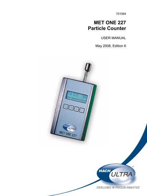
<strong>MET</strong> <strong>ONE</strong> <strong>227</strong><br />
<strong>Particle</strong> <strong>Counter</strong><br />
USER MANUAL<br />
May 2008, Edition 6
701094<br />
<strong>MET</strong> <strong>ONE</strong> <strong>227</strong><br />
<strong>Particle</strong> Detector<br />
USER MANUAL<br />
May 2008, Edition 6<br />
© Hach Ultra Analytics, Inc., 2008. All rights reserved. Printed in the U.S.A.
Table of Contents<br />
Section 1 Specifications.................................................................................................................... 5<br />
Section 2 General Information......................................................................................................... 7<br />
2.1 Safety information........................................................................................................................ 7<br />
2.1.1 Use of hazard information................................................................................................... 7<br />
2.1.2 Precautionary labels ........................................................................................................... 7<br />
2.1.3 Laser safety information...................................................................................................... 8<br />
2.1.4 Battery safety information ................................................................................................... 8<br />
2.1.5 Electrostatic discharge (ESD) considerations..................................................................... 8<br />
2.2 General product information ........................................................................................................ 9<br />
2.3 Theory of operation...................................................................................................................... 9<br />
Section 3 Installation........................................................................................................................ 11<br />
3.1 Unpack the instrument............................................................................................................... 11<br />
3.2 Installation guidelines for the <strong>MET</strong> <strong>ONE</strong> <strong>227</strong> particle counter ................................................... 11<br />
3.3 Mechanical installation............................................................................................................... 12<br />
3.3.1 Install the isokinetic probe................................................................................................. 12<br />
3.3.2 Install the purge filter......................................................................................................... 12<br />
3.3.3 Install the charging stand .................................................................................................. 13<br />
3.3.4 Connect the AC adapter ................................................................................................... 13<br />
3.3.5 Install the RH/T probe ....................................................................................................... 13<br />
3.4 Connections and adjustments.................................................................................................... 13<br />
Section 4 Operation.......................................................................................................................... 15<br />
4.1 Power up.................................................................................................................................... 15<br />
4.2 Factory default settings.............................................................................................................. 15<br />
4.3 Manual mode ............................................................................................................................. 15<br />
4.4 Automatic mode......................................................................................................................... 16<br />
4.4.1 Unlock the program mode................................................................................................. 19<br />
4.4.2 Set display (DSP) functions .............................................................................................. 19<br />
4.4.3 Set serial input/output (SIO) functions .............................................................................. 21<br />
4.4.4 Set clock (CLK) functions..................................................................................................21<br />
4.5 Average mode............................................................................................................................ 23<br />
4.6 Concentration mode................................................................................................................... 24<br />
4.7 Beep mode................................................................................................................................. 26<br />
4.8 Program the temperature probe................................................................................................. 28<br />
Section 5 Maintenance .................................................................................................................... 29<br />
5.1 Maintenance guidelines ............................................................................................................. 29<br />
5.2 Clean the sensor........................................................................................................................ 29<br />
Section 6 Troubleshooting ............................................................................................................. 31<br />
6.1 Common problems..................................................................................................................... 31<br />
6.2 Reset the counter....................................................................................................................... 31<br />
6.3 Troubleshoot the pump.............................................................................................................. 32<br />
6.3.1 Disassemble and clean the pump..................................................................................... 32<br />
6.3.2 Optimize the pump............................................................................................................ 35<br />
Section 7 Replacement Parts and Accessories......................................................................... 37<br />
7.1 Accessories................................................................................................................................ 37<br />
7.2 Optional accessories.................................................................................................................. 37<br />
Section 8 Service Contact Information........................................................................................ 39<br />
Section 9 Limited Warranty ............................................................................................................ 40<br />
Section 10 Certification ................................................................................................................... 41<br />
3
Table of Contents<br />
Appendix A Computer Interface Operations ..............................................................................43<br />
A.1 Data analysis for ISO 14644 ......................................................................................................43<br />
A.1.1 Computer communications ...............................................................................................43<br />
Appendix B PortAll Software..........................................................................................................47<br />
B.1 Connections ...............................................................................................................................47<br />
B.2 Operation ...................................................................................................................................47<br />
Appendix C DPU-414 Printer ..........................................................................................................49<br />
C.1 Printer setup ..............................................................................................................................49<br />
C.2 <strong>Counter</strong> setup for the printer......................................................................................................51<br />
C.3 Interpret the printout ..................................................................................................................52<br />
Index ......................................................................................................................................................53<br />
4
Section 1<br />
Specifications<br />
Specifications are subject to change without notice.<br />
General<br />
Dimension (W x H x L) 101.60 mm x 58.42 mm x 165.10 mm (4.0" x 2.3" x 6.5")<br />
Weight<br />
1 kg (2.13 lb)<br />
Maximum count displayed 9,999,999<br />
Sample flow rate<br />
0.1 cfm<br />
Number of size ranges<br />
2 (second size range can be selected at the front panel)<br />
<strong>Particle</strong> size ranges<br />
Coincidence error<br />
Power<br />
Light source<br />
Sample/hold times<br />
Count alarms<br />
Data storage<br />
Count cycles<br />
Locations<br />
Output<br />
Pump type<br />
Recharging time<br />
Battery type<br />
Operating time<br />
Environment<br />
Operating temperature<br />
Operating humidity<br />
Storage temperature<br />
Storage humidity<br />
<strong>MET</strong> <strong>ONE</strong> <strong>227</strong>A—0.5 micron and larger (channel 1); 0.7 micron, 1 micron, 3<br />
micron or 5 micron (channel 2)<br />
<strong>MET</strong> <strong>ONE</strong> <strong>227</strong>B—0.3 micron and larger (channel 1); 0.5 micron, 1 micron, 3<br />
micron or 5 micron (channel 2)<br />
Less than 5% at 2,000,000 particles/cubic foot<br />
+5 W, +10 V (approximately) (+6 V with battery pack)<br />
Laser diode<br />
1 second to 24 hours<br />
1 to 9,999,999 counts<br />
200 samples, rotating buffer<br />
Up to 100 in Auto or Average mode<br />
Up to 250 (number appears on the printout)<br />
RS232C/RS485 for computer<br />
Carbon vane, 0.1 cfm<br />
Up to 90% in 10 hours, 100% in 12 hours<br />
Rechargeable NiMH, 3500 mAH<br />
8 hours, typical<br />
12 to 29 °C (55 to 84 °F)<br />
10 to 85% relative humidity, non-condensing<br />
-40 to 71 °C (-40 to 160 °F)<br />
Up to 98% relative humidity, non-condensing<br />
5
Specifications<br />
6
Section 2<br />
General Information<br />
2.1 Safety information<br />
2.1.1 Use of hazard information<br />
2.1.2 Precautionary labels<br />
Read this entire manual before unpacking, setting up or operating this equipment. Pay<br />
attention to all danger and caution statements. Failure to do so could result in serious<br />
injury to the operator or damage to the equipment.<br />
To make sure that the protection provided by this equipment is not impaired, do not use<br />
or install this equipment in any manner other than that specified in this manual.<br />
DANGER<br />
Indicates a potentially or imminently hazardous situation which, if not avoided, will<br />
result in death or serious injury.<br />
WARNING<br />
Indicates a potentially or imminently hazardous situation which, if not avoided,<br />
could result in death or serious injury.<br />
CAUTION<br />
Indicates a potentially hazardous situation that can result in minor or<br />
moderate injury.<br />
Important Note: Indicates a situation which, if not avoided, can cause damage to the<br />
instrument. Information that requires special emphasis.<br />
Note: Information that supplements points in the main text.<br />
Read all labels and tags attached to the instrument. Personal injury or damage to the<br />
instrument could occur if not observed. A symbol, if noted on the instrument, will be<br />
included with a danger or caution statement in the manual.<br />
This symbol, if noted on the instrument, references the instruction manual for operation and/or safety information.<br />
Electrical equipment marked with this symbol cannot be disposed of in European public disposal systems after<br />
12 August of 2005. In conformity with European local and national regulations (EU Directive 2002/96/EC),<br />
European electrical equipment users must now return old or end-of life equipment to the Producer for disposal at no<br />
charge to the user.<br />
Note: To return for recycling, contact the equipment producer or supplier for instructions on how to return end-of-life<br />
equipment, producer-supplied electrical accessories and all auxiliary items for proper disposal.<br />
This symbol, when noted on a product enclosure or barrier, indicates that a risk of electrical shock and/or<br />
electrocution exists.<br />
This symbol, if noted on the product, indicates the need for protective eye wear.<br />
This symbol, when noted on the product, identifies the location of a fuse or current limiting device.<br />
This symbol indicates a laser device is used in the equipment.<br />
This symbol, when noted on the product, indicates the presence of devices sensitive to Electro-static Discharge<br />
(ESD) and indicated that care must be taken to prevent damage with the equipment.<br />
7
General Information<br />
2.1.3 Laser safety information<br />
2.1.4 Battery safety information<br />
This particle counter contains a laser-based sensor that is a Class 1 product (as defined<br />
by 21 CFR, Subchapter J, of the Health and Safety Act of 1968) when used under normal<br />
operation and maintenance. The manual contains no procedures for service of internal<br />
parts within this unit. Only factory-authorized personnel must perform the service.<br />
The particle counter has been evaluated and tested in accordance with EN<br />
61010-1:1993, "Safety Requirements For Electrical Equipment For Measurement, Control<br />
and Laboratory Use" and IEC 825-1:1993, "Safety of Laser Products".<br />
WARNING<br />
An explosion can occur if the internal battery is replaced incorrectly.<br />
Figure 1 shows the label that appears on the battery for the safety of the user.<br />
Figure 1 Battery safety label<br />
2.1.5 Electrostatic discharge (ESD) considerations<br />
Important Note: To minimize hazards and ESD risks, maintenance procedures not<br />
requiring power to the analyzer should be performed with power removed.<br />
Delicate internal electronic components can be damaged by static electricity, resulting in<br />
degraded instrument performance or eventual failure.<br />
The manufacturer recommends the user to take the following steps to prevent ESD<br />
damage to the instrument:<br />
• Before the user touches any instrument electronic components (such as printed circuit<br />
cards and the components on them) discharge static electricity. This can be<br />
accomplished by touching an earth-grounded metal surface such as the chassis of an<br />
instrument or a metal conduit or pipe.<br />
• To reduce static build-up, avoid excessive movement. Transport static-sensitive<br />
components in anti-static containers or packaging.<br />
• To discharge static electricity and keep it discharged, wear a wrist strap connected by<br />
a wire to earth ground.<br />
• Handle all static-sensitive components in a static-safe area. If possible, use anti-static<br />
floor pads and work bench pads.<br />
8
2.2 General product information<br />
2.3 Theory of operation<br />
General Information<br />
The <strong>MET</strong> <strong>ONE</strong> <strong>227</strong> particle counter is a battery operated, laser based particle counter<br />
that is used in a walk-around sampling routine. The <strong>MET</strong> <strong>ONE</strong> <strong>227</strong> particle counter stores<br />
up to 200 records with a different location label for each sample. The data records may<br />
later be printed or downloaded to a computer for analysis. The <strong>MET</strong> <strong>ONE</strong> <strong>227</strong> particle<br />
counter is used in environments where the particulate contamination does not exceed two<br />
million particles per cubic foot of air, such as clean-rooms, medical instrument<br />
assemblies, computer rooms and downstream of air filter installations in HVAC systems.<br />
The Concentration mode in the <strong>MET</strong> <strong>ONE</strong> <strong>227</strong> particle counter is used to take a brief<br />
sample and estimate the probable cleanliness in areas with unknown particulate levels.<br />
This is based on built-in calculations performed in the microprocessor of the <strong>MET</strong> <strong>ONE</strong><br />
<strong>227</strong> particle counter. Long term use of the <strong>MET</strong> <strong>ONE</strong> <strong>227</strong> particle counter in uncontrolled<br />
environments such as open air office spaces or outdoor air will require frequent sensor<br />
maintenance.<br />
The <strong>MET</strong> <strong>ONE</strong> <strong>227</strong> particle counter operates at a flow rate of 0.1 cubic foot per<br />
minute (cfm). The flow rate is required to set the sampling parameters. For instance, the<br />
<strong>MET</strong> <strong>ONE</strong> <strong>227</strong> particle counter takes 10 minutes to sample 1 cubic foot of air. To obtain<br />
the counts per cubic foot, multiply the results of a 1-minute sample by ten. All counts are<br />
reported as cumulative counts; that is, all the reported 0.3 micron particles are 0.3 micron<br />
and larger in size.<br />
The <strong>MET</strong> <strong>ONE</strong> <strong>227</strong>A/B particle counter is a combination of a sensor, pump and<br />
electronics (refer to Figure 2 on page 10) that includes full particle counter features. Both<br />
variants use the same sensor, pump, CPU and display electronics. The <strong>MET</strong> <strong>ONE</strong> <strong>227</strong>A<br />
particle counter is calibrated with channel 1 sensitivity of 0.5 micron and the <strong>MET</strong> <strong>ONE</strong><br />
<strong>227</strong>B particle counter is calibrated with a channel 1 sensitivity of 0.3 micron. Both operate<br />
at a flow rate of 0.1 cfm.<br />
The sample passes through a laser beam in the sensor, where the particles scatter the<br />
laser light. The sample then passes through a pump and a filter to trap particles in the<br />
counter rather than return them to the environment. The flashes of scattered light are<br />
converted to electronic pulses directly proportional to the amount of scatter, which<br />
creates a correlation to the particle size. The electronic pulses are counted and stored in<br />
channel bins in a data record. A data record also includes the date and time from the<br />
CPU clock and snapshots of the environmental conditions, if the Relative<br />
Humidity/Temperature (RH/T) probe is attached.<br />
9
General Information<br />
Figure 2 Theory of operation<br />
1 Sample inlet 5 Sample exhaust<br />
2 Sensor 6 Serial data out<br />
3 Pump 7 Control electronics<br />
4 Filter 8 Display<br />
10
Section 3<br />
Installation<br />
3.1 Unpack the instrument<br />
DANGER<br />
Only qualified personnel should conduct the tasks described in this section of<br />
the manual.<br />
This section describes the setup of the <strong>MET</strong> <strong>ONE</strong> <strong>227</strong> particle counter and connections to<br />
the equipment. If necessary, contact the Technical Support department with questions<br />
regarding the compatibility or suitability of this product for a specific application.<br />
Remove the components from the shipping container and inspect for damage. Verify that<br />
all the items listed in Figure 3 are included. If any items are missing or damaged, contact<br />
the manufacturer or sales representative.<br />
Retain the original packaging materials. Use the original packaging material to store or<br />
ship the instrument to protect against damage during storage or transportation.<br />
Figure 3 List of packaged items<br />
1 Isokinetic probe (Catalog No. 2080613) 4 <strong>MET</strong> <strong>ONE</strong> <strong>227</strong> particle counter<br />
2 Purge filter (Catalog No. 2080442) 5 AC adapter—115 VAC (Catalog No. 770007), 230VAC<br />
(Catalog No. 770012), 100 VAC (Catalog No. 770009)<br />
3 Charging stand (Catalog No. 2080469)<br />
3.2 Installation guidelines for the <strong>MET</strong> <strong>ONE</strong> <strong>227</strong> particle counter<br />
The <strong>MET</strong> <strong>ONE</strong> <strong>227</strong> particle counter is ready to use when shipped and is configured in a<br />
default mode (refer to section 4.2 on page 15).<br />
Before the operation of the <strong>MET</strong> <strong>ONE</strong> <strong>227</strong> particle counter, make sure that the following<br />
guidelines are complied to:<br />
• Remove the red sensor inlet cap and attach the isokinetic probe prior to sampling<br />
(refer to section 3.3.1 on page 12).<br />
• If the RH/T probe is used, attach it before the <strong>MET</strong> <strong>ONE</strong> <strong>227</strong> particle counter is<br />
turned on (refer to section 3.3.5 on page 13).<br />
11
Installation<br />
3.3 Mechanical installation<br />
3.3.1 Install the isokinetic probe<br />
The isokinetic probe (refer to Figure 4 on page 12, item 2) is used in the laminar air flow<br />
for a flow rate of up to 100 feet per minute.<br />
To install the isokinetic probe:<br />
1. Remove the red sensor inlet cap from the <strong>MET</strong> <strong>ONE</strong> <strong>227</strong> particle counter.<br />
Note: To minimize contamination, the isokinetic probe is protected with a cap on the opening<br />
that should remain in place till the probe is used.<br />
2. Attach the isokinetic probe to the sensor inlet so that the open end faces the direction<br />
of the air stream.<br />
Figure 4 Installation of the isokinetic and relative humidity/temperature probe<br />
1 Relative humidity/temperature probe 3 <strong>MET</strong> <strong>ONE</strong> <strong>227</strong> particle counter<br />
2 Isokinetic probe<br />
3.3.2 Install the purge filter<br />
The purge filter (refer to Figure 3 on page 11, item 2) is used for the maintenance of the<br />
<strong>MET</strong> <strong>ONE</strong> <strong>227</strong> particle counter. The filter prevents the contamination of the sensor and<br />
purges the sensor of accumulated internal particles.<br />
To install the purge filter:<br />
1. Remove the red sensor inlet cap or the isokinetic probe from the <strong>MET</strong> <strong>ONE</strong> <strong>227</strong><br />
particle counter.<br />
2. Attach the purge filter to the sensor inlet.<br />
12
3.3.3 Install the charging stand<br />
3.3.4 Connect the AC adapter<br />
3.3.5 Install the RH/T probe<br />
Installation<br />
The charging stand (refer to Figure 3 on page 11, item 3) is used to hold the <strong>MET</strong> <strong>ONE</strong><br />
<strong>227</strong> particle counter during recharge or when sampling from a stationary position.<br />
To install the charging stand:<br />
1. Install the charging stand on any stable surface.<br />
2. Place the <strong>MET</strong> <strong>ONE</strong> <strong>227</strong> particle counter on the charging stand.<br />
WARNING<br />
An explosion can occur if the internal battery is replaced incorrectly.<br />
The AC adapter (refer to Figure 3 on page 11, item 5) is used to charge the internal<br />
battery and use the <strong>MET</strong> <strong>ONE</strong> <strong>227</strong> particle counter with a standard 115 VAC outlet.<br />
To connect the AC adapter:<br />
1. Turn off power to the <strong>MET</strong> <strong>ONE</strong> <strong>227</strong> particle counter.<br />
2. Attach the AC adapter to the power input jack (refer to Figure 5 on page 13) on the<br />
bottom of the <strong>MET</strong> <strong>ONE</strong> <strong>227</strong> particle counter.<br />
To install the RH/T probe:<br />
1. Locate the connector for the RH/T probe (refer to Figure 4 on page 12, item 1) on top<br />
of the <strong>MET</strong> <strong>ONE</strong> <strong>227</strong> particle counter.<br />
2. Attach the RH/T probe to the inlet so that the open end faces the direction of the air<br />
stream.<br />
3.4 Connections and adjustments<br />
The power and serial I/O connectors and the power switch are at the bottom of the<br />
counter. The brightness of the display may be adjusted for optimum performance in<br />
various ambient light conditions as shown in Figure 5.<br />
Figure 5 Connections and adjustments<br />
1 Serial I/O connection 3 Power switch<br />
2 Display brightness adjustment 4 Power connection<br />
13
Installation<br />
14
Section 4<br />
4.1 Power up<br />
Operation<br />
Use the power switch at the bottom of the counter to turn on the <strong>MET</strong> <strong>ONE</strong> <strong>227</strong> particle<br />
counter (refer to Figure 5 on page 13, item 3). When first turned on, the counter will<br />
display the main screen (Figure 6 on page 16). The <strong>MET</strong> <strong>ONE</strong> <strong>227</strong> particle counter<br />
exhibits various counting modes. The factory default setting for the counting mode will be<br />
the Manual mode.<br />
4.2 Factory default settings<br />
Parameter<br />
Table 1 lists the default parameters that are programmed at the factory. Refer to Section<br />
4 on page 15 for a detailed explanation of the terms and instructions required for<br />
programming parameters.<br />
Setting<br />
Table 1 Default parameter settings<br />
Location number 000<br />
Count mode<br />
Manual (the counter will take one sample and stop counting)<br />
Alarm limits<br />
0 (no particle count level alarms will be registered)<br />
Channel 2 particle size 0.7 micron in <strong>227</strong>A; 0.5 micron in <strong>227</strong>B<br />
Volume<br />
Liters (applies to Concentration mode only)<br />
Temperature<br />
°C (only if RH/T probe is attached).<br />
RS232 mode<br />
Normal<br />
Baud rate 9600<br />
Sample time<br />
1 minute (length of sample period)<br />
Hold time<br />
1 second (hold time between samples in Automatic mode)<br />
Program mode<br />
Unlocked (allows user programming).<br />
4.3 Manual mode<br />
In the Manual mode, the <strong>MET</strong> <strong>ONE</strong> <strong>227</strong> particle counter takes one sample of<br />
programmed length (default is one minute) and stops. This operation is based on the<br />
factory default settings described in Table 1 on page 13.<br />
To initiate a 1-minute count cycle:<br />
1. Press 1 on the front panel (refer to Figure 6). The pump will begin to operate. The<br />
count cycle status will change from “Stop” to “Wait” for two seconds while the pump<br />
reaches maximum speed.<br />
The count cycle status (refer to Figure 6, item 2) will change to “Run” during the<br />
1-minute sample and return to “Stop” at the end of the count cycle. The <strong>MET</strong> <strong>ONE</strong> <strong>227</strong><br />
particle counter draws 0.1 cubic foot of air through the instrument. Multiply the results<br />
by ten to calculate the particle counts per cubic foot.<br />
15
Operation<br />
Figure 6 LCD display<br />
1 Channel 1 and channel 2 sizes (<strong>MET</strong> <strong>ONE</strong> <strong>227</strong>B) 5 Relative humidity<br />
2 Count cycle status 6 Keypad functions<br />
3 Channel 1 and channel 2 count results 7 Temperature<br />
4 Counting mode<br />
4.4 Automatic mode<br />
The Automatic mode is used to program sampling parameters. The Automatic mode<br />
covers the typical programming requirements for the common functions associated with<br />
the <strong>MET</strong> <strong>ONE</strong> <strong>227</strong> particle counter. Table 2 on page 17 describes all the common<br />
functions of the <strong>MET</strong> <strong>ONE</strong> <strong>227</strong> particle counter. The <strong>MET</strong> <strong>ONE</strong> <strong>227</strong> particle counter need<br />
not be programmed in a sequential order and any parameter may be programmed at any<br />
time without affecting the others.<br />
Figure 7 on page 17 shows an example of a program sampling pattern where a <strong>MET</strong><br />
<strong>ONE</strong> <strong>227</strong> particle counter is used to verify the cleanliness of a large room, dividing the<br />
space into eight sections for a comprehensive measurement.<br />
16
Operation<br />
1 Sections of a large room (1–8)<br />
Figure 7 Example of a sampling pattern<br />
Table 2 <strong>MET</strong> <strong>ONE</strong> <strong>227</strong> particle counter function descriptions<br />
Function<br />
Stop<br />
Wait<br />
Run<br />
Hold<br />
Location Num<br />
Count Mode = Manual (M)<br />
Count Mode = Auto (A)<br />
Count Mode = Average (Av)<br />
Count Mode = Concentration<br />
(CF or L)<br />
Period<br />
Count Mode = Beep (B)<br />
Num Cycles<br />
Ch 1 Lim<br />
Ch 2 Lim<br />
Ch 2 Size<br />
Volume =<br />
Description<br />
Count cycle status when the count cycles are complete.<br />
Count cycle status for 2-second pause to allow the pump to come up<br />
to speed before starting first count cycle.<br />
Count cycle status during a particle count cycle.<br />
Count cycle status during the pause between count cycles.<br />
Location number (0 to 250) can be set for a sample location as well<br />
as for an addressing number established for the counter<br />
(computer control).<br />
Counts for one count cycle; then turns pump off. <strong>Counter</strong> remains on.<br />
Repeats count cycles until all the cycles programmed are completed.<br />
Gives the average, minimum and maximum count for a specified<br />
number of count cycles.<br />
Approximates count per cubic foot of air (CF) or count/liter of air (L).<br />
Also changes temperature readout from °F to °C.<br />
Time (1 to 10 seconds) selected for count approximation when in<br />
Concentration mode.<br />
One beep after channel 1 and channel 2 count limit is reached and<br />
each step multiple thereafter. <strong>Counter</strong> counts until stopped.<br />
Number of count cycles (1 to 100 or INF) in Auto (A) and Average<br />
(Av) modes. If INF (Infinity) is selected, the counter will continue the<br />
count cycles until stopped.<br />
Count limit of channel 1 when an audible alarm begins.<br />
Count limit of channel 2 when an audible alarm begins.<br />
Minimum size threshold of particles counted in second size channel.<br />
Also, second size channel can be selected while in this function.<br />
Changes particle count readout when in Concentration mode from<br />
counts/liter to counts/cubic foot<br />
17
Operation<br />
Function<br />
Temp =<br />
RS232 Mode = Print a Record<br />
Changes temperature readout from °F to °C.<br />
When the printer is connected, results are printed at the end of each<br />
count cycle.<br />
RS232 Mode = Print Buffer<br />
When the printer is connected, the printer prints count data for all<br />
count cycles stored in buffer.<br />
RS232 Mode = Normal<br />
Printer is disabled; RS232 (computer control) is enabled.<br />
Buffer Cnt<br />
Number of count cycles presently stored in the buffer.<br />
Baud Rate Select from 300, 1200, 2400 or 9600.<br />
Date<br />
Present date<br />
Time<br />
Present time of day (24-hour clock format)<br />
Period<br />
Sample time for each count cycle (up to 24 hours)<br />
Hold<br />
Time between count cycles (up to 24 hours)<br />
Program Mode Is Unlocked (or Locked)<br />
<br />
<br />
<br />
(Program Mode)<br />
RUN<br />
STOP<br />
DSP<br />
SIO<br />
CLK<br />
PROG<br />
NXT<br />
BAK<br />
RET<br />
INC<br />
DEC<br />
→<br />
ZERO<br />
Table 2 <strong>MET</strong> <strong>ONE</strong> <strong>227</strong> particle counter function descriptions (continued)<br />
Description<br />
The counter can be locked so that the program settings cannot be<br />
changed.<br />
When flashing, indicates a sensor problem.<br />
When flashing and beeping, indicates that the programmed count<br />
alarm limit has been exceeded.<br />
When flashing, indicates battery needs recharging.<br />
Indicates that the user has entered the mode for changing<br />
parameters or limits of the display, serial I/O or clock functions.<br />
Begins the count cycle.<br />
Stops the count cycle before completion; data is not saved.<br />
Top menu name (Display) for all display parameters.<br />
Top menu item (Serial Input/Output) for all serial<br />
interface parameters.<br />
Top menu name (Clock) for all clock parameters.<br />
Allows user to change parameters or limits.<br />
Moves to the next function within the top menu.<br />
Moves to the previous function within the top menu.<br />
Returns to the main screen.<br />
Either moves to the next mode selection or increments (increases)<br />
the number settings.<br />
Either moves to the previous mode selection or decrements<br />
(decreases) the number settings.<br />
Advances to the next set of digits to be changed.<br />
Sets buffer count to zero (clears buffer of all count cycle data).<br />
18
Operation<br />
4.4.1 Unlock the program mode<br />
To program the <strong>MET</strong> <strong>ONE</strong> <strong>227</strong> particle counter, unlock the Program mode.<br />
Note: The Program mode is unlocked at the factory by default.<br />
To unlock the Program mode:<br />
1. Press 4 (CLK) on the main screen.<br />
2. Press 3 (BAK) to display the Program mode status screen (refer to Figure 8).<br />
3. Press 1 (PROG) to enter the Program mode.<br />
4. Press 2 (INC) to unlock the Program mode.<br />
5. Press 4 (RET) to return to the main screen.<br />
Figure 8 Program mode status screen<br />
4.4.2 Set display (DSP) functions<br />
4.4.2.1 Location number<br />
To set the location number:<br />
1. Press 2 (DSP) on the main screen. The Location Number screen is displayed<br />
(refer to Figure 9).<br />
2. Press 1 (PROG) to enter the Program mode.<br />
3. Press 2 (INC) to set the Location Number to 001.<br />
4. Press 4 (RET) to return to the main screen.<br />
Figure 9 Location number screen<br />
19
Operation<br />
4.4.2.2 Count mode<br />
To set the count mode:<br />
1. Press 2 (DSP) on the main screen.<br />
2. Press 2 (NXT) to display the Count mode screen.<br />
3. Press 1 (PROG) to enter the Program mode.<br />
4. Press 2 (INC) or 3 (DEC) to select the Automatic count mode (refer to Figure 10). Auto<br />
(A) repeats count cycles until all the count cycles programmed are complete.<br />
Figure 10 Automatic count mode screen<br />
5. Press 4 (RET). The Num Cycles screen is displayed in the Program mode<br />
(refer to Figure 11).<br />
Figure 11 Num cycles screen<br />
6. Press 2 (INC) and 3 (DEC) to select three count cycles. If infinity (INF) is selected, the<br />
<strong>MET</strong> <strong>ONE</strong> <strong>227</strong> particle counter will continue to count cycles until manually stopped.<br />
7. Press 4 (RET) to save the settings and return to the main screen.<br />
20
Operation<br />
4.4.3 Set serial input/output (SIO) functions<br />
4.4.3.1 Clear the memory buffer<br />
Clear the memory buffer to remove data records that were stored previously.<br />
To clear the memory buffer:<br />
1. Press 3 (SIO) on the main screen.<br />
2. Press 2 (NXT) to display the Buffer Count screen (refer to Figure 12).<br />
3. Press 1 (ZERO) to clear the contents of the buffer.<br />
Figure 12 Buffer count screen<br />
4.4.4 Set clock (CLK) functions<br />
4.4.4.1 Set the date and time<br />
To set the date and time:<br />
1. Press 4 (CLK) on the main screen. The Date and Time screen is displayed<br />
(refer to Figure 13).<br />
2. Press 1 (PROG) to enter the Program mode.<br />
3. Press 1 (→) to move the cursor along the digits.<br />
4. Press 2 (INC) and 3 (DEC) to set the current date and time. The date and time will<br />
appear on the data record for each sample.<br />
5. Press 4 (RET) to save the settings and return to the main screen.<br />
Figure 13 Date and time screen<br />
21
Operation<br />
4.4.4.2 Set sample period and hold times<br />
To set the sample Period and Hold times:<br />
1. Press 4 (CLK) on the main screen.<br />
2. Press 2 (NXT) to display the Period and Hold screen (refer to Figure 14).<br />
3. Press 1 (PROG) to enter the Program mode.<br />
4. Press 1 (→) to move the cursor along the digits.<br />
5. Press 2 (INC) and 3 (DEC) to set the Period time to 1 minute and the Hold time to<br />
1 second as shown.<br />
6. Press 4 (RET) to save the settings and return to the main screen.<br />
Figure 14 Period and hold screen<br />
Once all the parameters are set, begin to sample the room. One possible sampling<br />
pattern is as follows:<br />
1. Take the counter to the center of the first area to be tested.<br />
2. Place or hold the counter about 4 feet off the floor. Make sure that the opening of the<br />
isokinetic probe faces directly into the laminar flow.<br />
3. Press 1 (RUN) to initiate counting. The display shows three 1-minute samples being<br />
taken, separated by a 1-second hold time. When the three 1-minute samples are<br />
complete, the <strong>MET</strong> <strong>ONE</strong> <strong>227</strong> particle counter will stop the count.<br />
4. Move the <strong>MET</strong> <strong>ONE</strong> <strong>227</strong> particle counter to the next location that needs to be<br />
sampled. If required, reprogram the Location Number to reflect the movements in the<br />
room.<br />
5. When sampling is complete, print or download the count results. Analyze the results<br />
to verify the condition of the room.<br />
Note: The preceding steps may be modified to create a sampling pattern that fits specific needs.<br />
22
4.5 Average mode<br />
Operation<br />
In the Average mode, the <strong>MET</strong> <strong>ONE</strong> <strong>227</strong> particle counter counts for the number of<br />
sample periods programmed and then stops. The results displayed for both the channels<br />
are the average results of all the cycles. The minimum and maximum number of counts in<br />
all cycles are also displayed.<br />
To program the <strong>MET</strong> <strong>ONE</strong> <strong>227</strong> particle counter for Average mode:<br />
1. Press 2 (DSP) on the main screen.<br />
2. Press 2 (NXT) to display the Count mode screen (refer to Figure 15).<br />
Figure 15 Count mode screen<br />
3. Press 1 (PROG) to enter the Program mode.<br />
4. Press 2 (INC) or 3 (DEC) to select the Average mode.<br />
5. Press 4 (RET). The Num Cycles screen is displayed in the Program mode<br />
(refer to Figure 16).<br />
Figure 16 Num cycles screen in program mode<br />
6. Press 2 (INC) or 3 (DEC) to select the required period.<br />
7. Press 4 (RET) to save the settings and return to the main screen.<br />
8. Press 1 (RUN) to begin the count cycle. The count status display will display “Wait”<br />
while the pump comes up to speed, then display “RUN” when the <strong>MET</strong> <strong>ONE</strong> <strong>227</strong><br />
particle counter takes a sample. The <strong>MET</strong> <strong>ONE</strong> <strong>227</strong> particle counter will display<br />
“Hold” for the programmed Hold time between samples. When the programmed<br />
number of count cycles is complete, the <strong>MET</strong> <strong>ONE</strong> <strong>227</strong> particle counter will stop<br />
sampling and display the Completed Samples screen (refer to Figure 17 on page 24).<br />
Press 1, 2 or 3 to view the average, minimum and maximum counts respectively.<br />
9. Press 4 (RET) to return to the main screen.<br />
23
Operation<br />
Figure 17 Completed samples screen<br />
4.6 Concentration mode<br />
The Concentration mode in the <strong>MET</strong> <strong>ONE</strong> <strong>227</strong> particle counter can be used to take a<br />
quick snapshot of airborne particulate contamination levels, but cannot be used as a<br />
substitute for full sampling. The Concentration mode is appropriate for areas where the<br />
particulate levels are unknown and may exceed the operating limits of the <strong>MET</strong> <strong>ONE</strong> <strong>227</strong><br />
particle counter. When the Concentration mode is used, no data records are stored in the<br />
memory buffer.<br />
In the Concentration mode, the <strong>MET</strong> <strong>ONE</strong> <strong>227</strong> particle counter begins sampling and<br />
estimates the counts per cubic foot or per liter based on a programmable period of time.<br />
The <strong>MET</strong> <strong>ONE</strong> <strong>227</strong> particle counter updates the calculation results on the display at<br />
1-second intervals. The programmable period sets the size of a ‘calculation window’ in<br />
seconds, which is moved each second to incorporate the sample data for the next<br />
second. The sample data for the oldest second of the previous period is then discarded.<br />
The <strong>MET</strong> <strong>ONE</strong> <strong>227</strong> particle counter calculates the concentration based on a 3-second<br />
window that moves every one second (refer to Figure 18). The <strong>MET</strong> <strong>ONE</strong> <strong>227</strong> particle<br />
counter uses a 10-second period to calculate the concentration based on a 10-second<br />
window that moves every one second.<br />
Figure 18 Concentration mode (3-second period)<br />
1 3-second period 3 Recalculation and display update<br />
2 Seconds<br />
24
Operation<br />
A 10-second period is more likely to give a good representation of the actual<br />
concentration because it covers a longer period. Longer periods allows high particulate<br />
levels to contaminate the sensor (refer to Figure 19). Use a shorter period for<br />
unknown environments.<br />
Figure 19 Concentration mode (10-second period)<br />
1 10-second period 3 Recalculation and display update<br />
2 Seconds 4<br />
To program the <strong>MET</strong> <strong>ONE</strong> <strong>227</strong> particle counter for the Concentration mode:<br />
1. Press 2 (DSP) on the main screen.<br />
2. Press 2 (NXT) to display the Count mode screen (refer to Figure 20).<br />
Figure 20 Count mode screen<br />
3. Press 1 (PROG) to enter the Program mode.<br />
4. Press 2 (INC) or 3 (DEC) to select the Concentration mode.<br />
5. Press 4 (RET) to display the Period screen in the Program mode (refer to Figure 21<br />
on page 26).<br />
25
Operation<br />
Figure 21 Period screen<br />
6. Press 2 (INC) and 3 (DEC) to select the required period.<br />
7. Press 4 (RET) to save the settings and return to the main screen.<br />
8. Press 2 (DSP) and then press 2 (NXT) four times to display the Volume screen (refer<br />
to Figure 22).<br />
Figure 22 Volume screen<br />
4.7 Beep mode<br />
9. Press 1 (PROG) to enter the Program mode.<br />
10. Press 2 (INC) and 3 (DEC) to select the unit of volume.<br />
11. Press 4 (RET) to save the settings and return to the main screen.<br />
12. Press 1 (RUN) to begin the count cycle. The count status display will display “Wait”<br />
while the pump comes up to speed. The count status display then displays “RUN”<br />
while the counter takes a sample. In the Concentration mode, counting continues<br />
until 1 (STOP) is pressed.<br />
In the Beep mode, a single audible sound beeps once, every time a count alarm limit is<br />
reached and then once more for every multiple of the count limit. For example, if the limit<br />
is set at 1,000 particles, the beep will sound at 1,000, 2,000, 3,000 and so on. There are<br />
two size channels displayed at once and the <strong>MET</strong> <strong>ONE</strong> <strong>227</strong> particle counter beeps when<br />
either particle size range limit is reached. Set a limit for only one size range of interest<br />
and set the remaining range to zero, which generates no alarm. The Beep mode limits<br />
and count alarm limits are the same.<br />
26
Operation<br />
To program the <strong>MET</strong> <strong>ONE</strong> <strong>227</strong> particle counter for the Beep mode:<br />
1. Press 2 (DSP) on the main screen.<br />
2. Press 2 (NXT) to display the Count mode screen (refer to Figure 23).<br />
Figure 23 Count mode<br />
3. Press 1 (PROG) to enter the Program mode.<br />
4. Press 2 (INC) or 3 (DEC) to select the Beep mode.<br />
5. Press 4 (RET) to return to the main screen.<br />
6. Press 2 (DSP) on the main screen and then press 2 (NXT) twice to display the Alarm<br />
Limits screen (refer to Figure 24).<br />
7. Press 1 (PROG) to enter the Program mode.<br />
8. Press 1 (→) to move the cursor along the digits.<br />
9. Press 2 (INC) or 3 (DEC) to set the alarm limits for the required settings time to<br />
1 minute and the Hold time to 1 second (refer to Figure 24).<br />
Figure 24 Set the alarm limit and hold time<br />
10. Press 4 (RET) to save the settings and return to the main screen.<br />
11. Press 1 (RUN) to begin the count cycle. The count status display will display “Wait”<br />
while the pump comes up to speed. The count status display will then display “RUN”<br />
while the counter is taking a sample. In the beep mode, counting continues until 1<br />
(STOP) is pressed.<br />
27
Operation<br />
4.8 Program the temperature probe<br />
The <strong>MET</strong> <strong>ONE</strong> <strong>227</strong> particle counter displays the temperature readings of the optional<br />
environmental probe in degree Celsius (°C) or degrees Fahrenheit (°F).<br />
To program the temperature display:<br />
1. Press 2 (DSP) on the main screen and then repeatedly press 2 (NXT) to display the<br />
Temperature screen (refer to Figure 25).<br />
Figure 25 Temperature screen<br />
2. Press 1 (PROG) to enter the Program mode.<br />
3. Press 2 (INC) or 3 (DEC) to select the Beep mode.<br />
4. Press 4 (RET) to return to the main screen.<br />
28
Section 5<br />
Maintenance<br />
5.1 Maintenance guidelines<br />
5.2 Clean the sensor<br />
DANGER<br />
Only qualified personnel should conduct the tasks described in this section of<br />
the manual.<br />
DANGER<br />
Electrocution hazard. Always disconnect the power to the instrument before<br />
making any electrical connections.<br />
WARNING<br />
Harmful radiation exposure. Do not use the controls or adjustments or<br />
performance of procedures other than those specified.<br />
CAUTION<br />
Electrostatic discharge (ESD) can damage or destroy electronic components. All<br />
work inside the particle counter should be done at a static-safe workstation.<br />
A static-safe workstation can be created by doing the following:<br />
• Use a grounded conductive table mat and resistor-isolated wrist-strap combination.<br />
• Earth-ground all test instruments to prevent a build-up of static discharge.<br />
Important Note: The laser diode in this device is extremely sensitive to static charges and<br />
out-of-tolerance voltage variations.<br />
Important Note: Never connect or disconnect the sensor cable from the counter when the<br />
counter is on.<br />
To clean the sensor:<br />
1. Remove the four screws (two on each side) from the <strong>MET</strong> <strong>ONE</strong> <strong>227</strong> particle counter.<br />
2. Remove the two screws from the bracket on the top end of the <strong>MET</strong> <strong>ONE</strong> <strong>227</strong><br />
particle counter.<br />
3. Open the two halves of the unit apart. Pull the back of the unit slightly downward to<br />
enable the sensor inlet to have an opening at the top of the counter.<br />
4. Remove the four nylon screws that hold the sensor to the case.<br />
5. Disconnect the tubing from the sensor.<br />
6. Disconnect the sensor cable from the sensor circuit board.<br />
7. Insert two #2-56 machine screws into the two threaded holes in the reflector. Use<br />
these screws as a handle to remove the reflector with a pulling and twisting motion.<br />
8. Clean the reflector and photo detector with cotton swabs dipped in a small amount of<br />
reagent grade Acetone. Wipe the optical surfaces with a dry swab. Blow the dust out<br />
of the interior surfaces with clean dry air.<br />
9. Perform steps 1 to 8 in the reverse order to assemble the <strong>MET</strong> <strong>ONE</strong> <strong>227</strong><br />
particle counter.<br />
29
Maintenance<br />
30
Section 6<br />
Troubleshooting<br />
6.1 Common problems<br />
Table 3 Troubleshooting procedures<br />
Message displayed on the LCD Description Cause/User action<br />
<br />
<br />
<br />
Indicates that the<br />
battery needs to be<br />
recharged.<br />
Indicates that the<br />
internal particle sensor<br />
is no longer operating<br />
within acceptable<br />
limits. Any count data<br />
taken during this alarm<br />
condition is<br />
disregarded as<br />
inaccurate.<br />
Indicates that the<br />
particle counts have<br />
exceeded the<br />
programmed limits, but<br />
does not indicate a<br />
failure in the counter.<br />
1 Turn off the counter and attach the AC adapter/charger to<br />
the power input jack at the bottom of the counter.<br />
2 Place the counter on the charging stand or on any stable<br />
surface and allow it to charge for 10 to 12 hours.<br />
The primary cause of this condition is sensor contamination.<br />
When this alarm occurs:<br />
1 Purge the sensor by attaching the purge filter that is<br />
supplied with the counter to the sensor inlet on top of the<br />
counter.<br />
2 Place the counter on the stand and attach the AC<br />
adapter/charger to the power connection on the bottom of<br />
the counter.<br />
3 Set the counter to Automatic mode and the number of<br />
cycles to infinite (INF).<br />
4 Press RUN and observe the particle count display. If the<br />
count totals are high but descending, allow the counter to<br />
operate continuously for an extended period of time until<br />
the counts stabilize at or near zero. If the <br />
alarm persists or if the counts do not reach zero after an<br />
extended period of time, clean the sensor (refer to<br />
section 5.2 on page 29).<br />
Make sure that the alarm limits are set to an appropriate level for<br />
the environment being monitored.<br />
6.2 Reset the counter<br />
If for any reason the <strong>MET</strong> <strong>ONE</strong> <strong>227</strong> particle counter begins to perform out of character<br />
(for example, incorrect date and time), clear the counter memory and start the<br />
microprocessor again.<br />
To reset the counter:<br />
1. Disconnect any printer and serial cables. Turn the power off.<br />
2. Hold down 1 and 2 while turning the power on. Release the keys when the <strong>MET</strong> <strong>ONE</strong><br />
<strong>227</strong> particle counter beeps once. The Default mode screen is displayed (refer to<br />
Figure 26 on page 32).<br />
31
Troubleshooting<br />
Figure 26 Default mode screen<br />
6.3 Troubleshoot the pump<br />
3. Press 4 (RET) to return to the main screen.<br />
4. Program the date and time and any other function that may have been set to original<br />
default values.<br />
If the vacuum pump does not operate or exhibits any questionable symptoms such as<br />
unusual sound or vibration, it may be removed for maintenance to restore it to optimum<br />
operation.<br />
6.3.1 Disassemble and clean the pump<br />
Prerequisites:<br />
• 1.27 mm or 1.5 mm Allen wrench<br />
To disassemble and clean the pump:<br />
1. Open the counter as described in steps 1 to 3 of section 5.2 on page 29.<br />
2. Remove the pump from the chassis clip.<br />
Figure 27 Pump<br />
3. Unplug the pump electrical connection.<br />
4. Disconnect the tubing from the pump.<br />
Note: Make note of the tubing that is attached to the Vacuum (V) fitting and the Pressure (P)<br />
fitting. This information is required for the assembly of the pump.<br />
32
Troubleshooting<br />
5. Use a 1.27 mm or 1.5 mm hex key (Allen) wrench to loosen the set screw in the<br />
bracket on top of the pump.<br />
1<br />
1 Hex key wrench<br />
Figure 28 Loosening of the set screw<br />
6. Push the bracket to one side and remove it from the pump (refer to Figure 29).<br />
1<br />
1 Bracket<br />
Figure 29 Removal of the bracket<br />
7. Remove the top of the pump (refer to Figure 30) and locate the locator pin.<br />
1<br />
2<br />
Figure 30 Removal of the top of the pump<br />
1 Locator pin 2 Top of the pump<br />
33
Troubleshooting<br />
8. Remove the pump body (refer to Figure 31).<br />
1<br />
1 Pump body<br />
Figure 31 Removal of the pump body<br />
9. Remove the carbon vanes (refer to Figure 32 on page 34 and Figure 33 on page 34)<br />
and make sure that the rotor turns freely.<br />
1<br />
1 Carbon vane<br />
Figure 32 Removal of carbon vanes<br />
Figure 33 After removal of carbon vanes<br />
10. Perform steps 1 to 9 in the reverse order to assemble the pump into the counter.<br />
34
Troubleshooting<br />
6.3.2 Optimize the pump<br />
To optimize the pump:<br />
1. After the assembly of the pump, loosen the set screw plug in the bracket. Connect<br />
the set screw plug to the <strong>MET</strong> <strong>ONE</strong> <strong>227</strong> particle counter.<br />
2. Turn on power to the <strong>MET</strong> <strong>ONE</strong> <strong>227</strong> particle counter.<br />
3. Press 1 (RUN) to initiate a count cycle and turn on the pump.<br />
4. Hold the pump motor still.<br />
5. Rotate the entire pump head in a 180° arc (refer to Figure 34).<br />
Figure 34 Rotation of the pump head<br />
6. As the pump head is rotated listen for the point where the Revolutions per Minute<br />
(RPMs) are the greatest.<br />
7. Keep the pump head steady and tighten the set screw.<br />
35
Troubleshooting<br />
36
Section 7<br />
Replacement Parts and Accessories<br />
7.1 Accessories<br />
Description Quantity Catalog no.<br />
Isokinetic probe 1 2080613<br />
Purge filter 1 2080442<br />
AC adapter 1<br />
770007 (115 VAC)<br />
770012 (230 VAC)<br />
770009 (100 VAC)<br />
Charging stand 1 2080469<br />
7.2 Optional accessories<br />
RH/T probe<br />
The RH/T probe is attached to the connector on top of the <strong>MET</strong> <strong>ONE</strong> <strong>227</strong> particle<br />
counter. The probe monitors the relative humidity (10 to 90%) and temperature (5 to<br />
122 °F or -15 to 50 °C). The <strong>MET</strong> <strong>ONE</strong> <strong>227</strong> particle counter displays and stores the<br />
readings in the internal particle count data record. Refer to section 3.3.5 on page 13 for<br />
installation instructions.<br />
Figure 35 RH/T probe (2080825)<br />
High-pressure diffuser<br />
The high-pressure diffuser is connected to the sensor inlet tubing of the <strong>MET</strong> <strong>ONE</strong> <strong>227</strong><br />
particle counter. The diffuser permits the direct sampling of pressurized air at pressures<br />
that range from 30 to 150 psi.<br />
Figure 36 High-pressure diffuser (2080372-6)<br />
RS485 converter<br />
The RS485 converter converts data from the RS232 to RS485 format for longer serial<br />
networking to a computer. Consult Technical Support for installation.<br />
Figure 37 RS485 converter (2082383-2)<br />
37
Replacement Parts and Accessories<br />
PortAll software<br />
The PortAll software is used to transfer count data from the buffer of the counter and to<br />
display the data on the computer in a spreadsheet format. The software performs<br />
calculations as per the FS 209E and ISO 14644 standards. The software includes an<br />
adapter for use with a standard 9-pin serial cable. Refer to Appendix B on page 47 for<br />
additional information.<br />
Figure 38 PortAll software (2084045)<br />
Carrying case<br />
The carrying case protects the particle counter during shipment and storage.<br />
Figure 39 Carrying case (2080878)<br />
38
Section 8<br />
Service Contact Information<br />
U.S.A. customers<br />
By Telephone:<br />
(541) 472-6500<br />
6:30 a.m. to 5:00 p.m. PST<br />
Monday through Friday<br />
By Fax:<br />
(541) 474-7414<br />
By Mail:<br />
Hach Ultra<br />
481 California Avenue<br />
Grants Pass, Oregon 97526<br />
Email:<br />
TechSupportGP@hachultra.com<br />
Website:<br />
www.hachultra.com<br />
International customers<br />
By Telephone:<br />
41 22 594 64 00<br />
Information required<br />
By Fax:<br />
41 22 594 64 99<br />
By Mail:<br />
Hach Ultra<br />
Service Department<br />
6, route de Compois, C.P. 212,<br />
CH-1222 Vésenaz, Geneva, Switzerland<br />
Website:<br />
www.hachultra.com<br />
• Your name • Model number<br />
• Your phone number • Serial number<br />
• Your company name • Comment or question<br />
• Your fax number<br />
39
Section 9<br />
Limited Warranty<br />
Hach Ultra warrants this instrument to be free of defects in materials and workmanship for a period of<br />
one year from the shipping date. If any instrument covered under this warranty proves defective during<br />
this period, Hach Ultra will, at its option either repair the defective part without charge for extra parts and<br />
labor or provide an equivalent replacement in exchange for the defective product.<br />
If any diode covered under this warranty proves defective during this period, Hach Ultra will, at its option,<br />
either repair the defective diode without charge for parts and labor or provide an equivalent replacement<br />
in exchange for the defective product.<br />
To obtain service under this warranty, the customer must notify the nearest Hach Ultra service support<br />
center on or before the expiration of the warranty period and follow their instructions for return of the<br />
defective instrument. The customer is responsible for all costs associated with packaging and<br />
transporting the defective unit to the service support center and must prepay all shipping charges. Hach<br />
Ultra will pay for return shipping if the shipment is to a location within the same country as the service<br />
support center.<br />
This warranty shall not apply to any defect, failure or damage caused by improper use or maintenance or<br />
by inadequate maintenance or care. This warranty shall not apply to damage resulting from attempts by<br />
personnel other than Hach Ultra representatives or factory authorized and trained personnel, to install,<br />
repair or service the instrument; to damage resulting from improper use or connection to incompatible<br />
equipment; or to instruments that have been modified or integrated with other products when the effect<br />
of such modification or integration materially increases the time or difficulty of servicing the instrument.<br />
THIS WARRANTY IS GIVEN BY HACH ULTRA ANALYTICS WITH RESPECT TO THIS INSTRUMENT<br />
IN LIEU OF ANY OTHER WARRANTIES, EXPRESSED OR IMPLIED. HACH ULTRA ANALYTICS<br />
AND ITS VENDORS DISCLAIM ANY IMPLIED WARRANTIES OF MERCHANTABILITY OR FITNESS<br />
FOR A PARTICULAR NON-CONTRACTUAL PURPOSE. HACH ULTRA ANALYTICS’<br />
RESPONSIBILITY TO REPAIR OR REPLACE DEFECTIVE PRODUCTS IS THE SOLE AND<br />
EXCLUSIVE REMEDY PROVIDED TO THE CUSTOMER FOR BREACH OF THIS WARRANTY.<br />
HACH ULTRA ANALYTICS AND ITS VENDORS WILL NOT BE LIABLE FOR ANY INDIRECT,<br />
SPECIAL, INCIDENTAL OR CONSEQUENTIAL DAMAGES EVEN IF HACH ULTRA ANALYTICS OR<br />
ITS VENDORS HAS BEEN GIVEN ADVANCED NOTICE OF THE POSSIBILITY OF SUCH<br />
DAMAGES.<br />
40
Section 10<br />
Certification<br />
DECLARATION of CONFORMITY<br />
We,<br />
Pacific Scientific Instruments<br />
481 California Avenue<br />
Grants Pass, Oregon 97526<br />
declare under sole responsibility that the<br />
<strong>Particle</strong> <strong>Counter</strong>, Model <strong>227</strong>, part number 2082611<br />
conforms to Directive 89/336/EEC for Electromagnetic Compatibility and Directive<br />
73/23/EEC for Low Voltage. Compliance was demonstrated to the following specifications<br />
as listed in the official Journal of the European Communities:<br />
EN 61326:1998, Class A / EN 500081-1:1992 Emissions:<br />
EN 55011 :1991 Class A Radiated<br />
EN 55011 :1991 Class A Conducted<br />
EN 61326:1998 / EN 50082-1:1997 Immunity:<br />
EN 61000-4-2 Electrostatic Discharge<br />
EN 61000-4-3 Electromagnetic Field<br />
EN 61000-4-4 Electrical Fast Transient<br />
EN 61000-4-5 Surge Test Common and Differential mode<br />
EN 61000-4-6 3 Volt Modulated Interfering Signal<br />
EN 61000-4-8 Susceptible Magnetic Fields<br />
EN 61000-4-11 Voltage Interruption Test<br />
EN 61010-1:1993 Amendment 1 & 2, Safety Requirement for Electrical Equipment for<br />
Measurement, Control and Laboratory Use<br />
EN 60825-1:1993 Safety of Laser Products, Equipment Classification, Requirements and<br />
User’s Guide.<br />
Pacific Scientific Instruments<br />
July 6, 2000<br />
(Place and date of issue)<br />
R. W. Ferguson-Engineering Director<br />
(Name/signature of authorized person)<br />
30<br />
41
Certification<br />
42
Appendix A Computer Interface Operations<br />
A.1 Data analysis for ISO 14644<br />
A.1.1 Computer communications<br />
The primary reason for a computer interface with the <strong>MET</strong> <strong>ONE</strong> <strong>227</strong> particle counter is to<br />
download the count data for analysis.<br />
ISO 14644 is the governing standard for clean-rooms. The <strong>MET</strong> <strong>ONE</strong> <strong>227</strong> particle<br />
counter cannot perform the calculations internally. Use the PortAll ® software package<br />
offered by the manufacturer along with the <strong>MET</strong> <strong>ONE</strong> <strong>227</strong> particle counter to download<br />
data from the counter. Perform all the necessary functions to make sure that there is<br />
compliance to the ISO standard. Refer to Appendix B on page 47 for instructions to setup<br />
and operate the <strong>MET</strong> <strong>ONE</strong> <strong>227</strong> particle counter with the PortAll software.<br />
The <strong>MET</strong> <strong>ONE</strong> <strong>227</strong> particle counter has been setup for RS232 and Rs485 serial data<br />
communications capabilities:<br />
• RS232 serial interface circuitry—Provides asynchronous communications between<br />
the counter and computer.<br />
• RS485 serial network circuitry—Provides asynchronous communications between up<br />
to 64 counters and a controlling computer.<br />
A terminal program such as Windows HyperTerminal ® is used to perform the basic<br />
communication. The <strong>MET</strong> <strong>ONE</strong> particle counter uses a special serial cable (Catalog No.<br />
2082197–1) available from the manufacturer. The pin configuration of the cable is shown<br />
in Figure 40. The backshell of the cable must be modified to fit the recessed connector on<br />
the <strong>MET</strong> <strong>ONE</strong> <strong>227</strong> particle counter.<br />
T×D<br />
R×D<br />
GnD<br />
1 1<br />
2 2<br />
3 3<br />
4 4<br />
7 5<br />
5 6<br />
6 7<br />
8 8<br />
9 9<br />
Figure 40 Serial interface pinout<br />
DCD<br />
R×D<br />
T×D<br />
DTR<br />
Sig. Gnd<br />
DSR<br />
RTS<br />
CTS<br />
RI<br />
43
A.1.1.1 Communication protocol<br />
The counter has the following fixed parity and protocol:<br />
• Eight (8) data bits<br />
• One (1) stop bit<br />
• No parity<br />
Table 4 describes the ASCII commands that are supported by the <strong>MET</strong> <strong>ONE</strong> <strong>227</strong><br />
particle counter.<br />
Table 4 ASCII commands supported by the counter<br />
ASCII command<br />
"a" Auto:<br />
"b" Manual:<br />
"c" Start Counting (computer controlled):<br />
"d" Start Counting (counter controlled):<br />
"e" Stop Counting:<br />
"C" Clear Buffer:<br />
"D" Send Number of Records:<br />
"E" Send EPROM Revision:<br />
"M" Mode Request:<br />
"T" Identify Model:<br />
"A" Send Record:<br />
"R" Resend Record:<br />
"h" Standby Mode:<br />
"g" Active Mode:<br />
"l" Local Mode:<br />
"U" Universal Select:<br />
"128-191" <strong>Counter</strong> Select:<br />
Description<br />
When the "a" command is used, the counter is placed in the Auto mode.<br />
When the "b" command is used, the counter is placed in the Manual mode.<br />
The counter will begin counting without waiting for an even second boundary<br />
(quick start). Counting will continue until stopped by the computer. The computer<br />
must control the count cycle.<br />
The counter will begin counting and control the count cycle based on the counter's<br />
setting for period.<br />
The counter will immediately stop counting without waiting for an even<br />
second boundary.<br />
The rotating buffer will be erased.<br />
The counter will send the number of records in the rotating buffer.<br />
The counter will send the EPROM number and revision level.<br />
The counter will send the present mode. If counting, a "C" will be sent. If holding, a<br />
"H" will be sent. If stopped, an "S" will be sent.<br />
The counter will send a 4-character model number (for example, <strong>227</strong>A).<br />
The next record in the rotating buffer will be sent. When the rotating buffer is<br />
empty, a "#" will be sent. Each record is erased from the buffer as it is sent. If no<br />
count cycles have been completed since the counter was turned on, then a "#" will<br />
be sent. The record cannot be sent until the current count cycle is complete.<br />
The last record sent will be sent again. Records sent prior to the last record have<br />
been permanently erased.<br />
The counter will enter a mode that turns off the air pump and shuts down the<br />
sensor to conserve power and reduce equipment wear.<br />
The counter will enter a mode that prepares it for counting. The air pump will turn<br />
on to purge the air path.<br />
The counter will be set to offline (for factory test purposes).<br />
The counter will respond to all commands after receiving this command,<br />
regardless of which select code is programmed into the counter until a counter<br />
select command is received (functions only when one counter is connected at a<br />
time). Any counter select command (128 through 191) will disable the Universal<br />
Select command. Enable this command again by turning off power to the unit and<br />
then turning it on.<br />
The counter will respond to all subsequent commands when a number is sent that<br />
matches the select code, that is, sending a number between 128 (corresponding to<br />
LOC 0) and 191 (corresponding to LOC 63) that does not equal the select code of<br />
the counter. The counter is deselected or made unresponsive to computer<br />
commands by selecting another counter.<br />
44
A.1.1.2 Data record format<br />
Each counter can send a record of the data available. The data record is a string of ASCII<br />
characters where the position in the string identifies the meaning of the character. The<br />
length of the string changes with the amount of data points available from the counter.<br />
Each data point is preceded by a 3-character tag that identifies the type of data that<br />
follows in the next six data characters. Figure 41 shows an example of the serial<br />
communications format of a two-channel particle counter. CRLF is the carriage return and<br />
line feed command.<br />
Figure 41 Serial communications format example<br />
1 Status 9 Relative humidity<br />
2 Date 10 Location<br />
3 Time 11 Checksum<br />
4 Period 12 End message<br />
5 Channel 1 13 Size<br />
6 Channel 2 14 Count<br />
7 Channel 6 15 Tag<br />
8 Temperature 16 Value<br />
45
Appendix B PortAll Software<br />
B.1 Connections<br />
The clean-room classification standards FS 209E and ISO 14644–1 require specific<br />
particle count measurements and calculations to verify the cleanliness level of a<br />
clean-room or clean area. The PortAll software can use the measurement data from the<br />
<strong>MET</strong> <strong>ONE</strong> <strong>227</strong> particle counter to generate clean-room verification results automatically.<br />
Note: The PortAll software is provided with an adapter that can be used use with a standard 9-pin to<br />
9-pin serial cable instead of a special cable that is required for a serial interface.<br />
In order to communicate with a computer, set the RS232 mode below the SIO menu to<br />
Normal (printer disabled). Make sure that the location number is set between 0 and 31<br />
(refer to Figure 42). This enables the PortAll software to recognize the <strong>MET</strong> <strong>ONE</strong> <strong>227</strong><br />
particle counter. After any communication with the computer, the keypad of the<br />
<strong>MET</strong> <strong>ONE</strong> <strong>227</strong> particle counter is disabled until the power is cycled off and on.<br />
Figure 42 <strong>MET</strong> <strong>ONE</strong> <strong>227</strong> particle counter connections<br />
1 Computer 3 Standard 9-pin serial cable<br />
2 PortAll adapter 4 <strong>MET</strong> <strong>ONE</strong> <strong>227</strong> particle counter<br />
B.2 Operation<br />
Perform the following procedures to make sure that an accurate classification result is<br />
obtained from the PortAll software.<br />
• The data returned from the particle counter contains a location number for each<br />
sample. Use the front panel instrument controls to change the location number each<br />
time the instrument is moved to a new location.<br />
Note: The PortAll software relies on the location number as an accurate indicator of the number<br />
of sample locations and number of samples per location.<br />
• Set the sample time to obtain the required sample volume at each location (Sample<br />
Time x Instrument Flow Rate = Sample Volume). The PortAll software does not have<br />
access to the instrument flow rate and has no way to verify that the sample volume<br />
complies with standard requirements. It is necessary to set up the <strong>MET</strong> <strong>ONE</strong> <strong>227</strong><br />
particle counter as follows:<br />
• Sample period to one minute (0.1 cubic ft) and select Normalize Data (counts x<br />
10) in PortAll<br />
OR<br />
• Sample period to 10 minutes (1.0 cubic ft) and do not select Normalize Data<br />
in PortAll<br />
47
• The total count data returned from the particle counter must be normalized to counts<br />
per unit volume to obtain a correct classification. The PortAll software will<br />
automatically normalize (counts x 10) the count data. Refer to the online User's Guide<br />
for instructions to set up this feature. The data normalization settings for a particular<br />
instrument are saved based on the instrument address. For most instruments, the<br />
sample location (LOC) value is also the serial port address. Make sure that the<br />
instrument address is reset after collecting samples in the clean-room and before<br />
connecting the instrument to the PortAll software. Otherwise, the count values will not<br />
be automatically normalized.<br />
Note: Make sure that the address value does not exceed 31. PortAll will not recognize an<br />
instrument whose address is outside the range of 0 to 31.<br />
• For ISO 14644-1—PortAll stores the ISO classification limits internally in a table<br />
as counts per cubic meter. To obtain accurate classifications, the data in the<br />
spreadsheet must be normalized to counts per cubic meter.<br />
• For FS209E—PortAll stores the FS 209E classification limits as counts per cubic<br />
foot. To obtain accurate classifications, the data in the spreadsheet must be<br />
normalized to counts per cubic foot.<br />
• Clear the instrument memory before beginning a sampling sequence to classify a<br />
clean-room or clean area. The PortAll spreadsheet of the instrument memory will then<br />
contain only relevant samples to select for the classification calculations.<br />
Note: For full PortAll documentation, refer to the PortAll CD.<br />
48
Appendix C DPU-414 Printer<br />
C.1 Printer setup<br />
The Model DPU-414 printer (refer to Figure 43 on page 49) is an accessory of the <strong>MET</strong><br />
<strong>ONE</strong> <strong>227</strong> particle counter.<br />
DIP switch settings for the DPU-414 printer are made in the internal firmware of the<br />
printer with the use of the front panel buttons of the printer.<br />
Figure 43 Model DPU-414 printer<br />
1 Power switch 3 FEED button<br />
2 ONLINE button<br />
To set up the printer:<br />
1. Turn the power switch off. Press and hold the ONLINE button.<br />
2. Turn on the power switch.<br />
3. When the printer begins to print the current DIP switch settings, release the ONLINE<br />
button. The current settings will be printed and the printer will be in the DIP switch<br />
setting mode. If the DIP switch settings match the settings in Table 5 on page 50, no<br />
changes are necessary.<br />
4. Press the FEED button to exit the DIP switch setting mode. If changes are necessary,<br />
proceed to step 5.<br />
5. Press the ONLINE button to begin the programming of DIP SW-1 settings. The printer<br />
will print "Dip SW-1" and open the first switch position.<br />
6. Press the FEED button to set the first DIP switch position off. The printer will print "1<br />
(OFF) : Input = Serial" and open the next switch position.<br />
7. Press the ONLINE button to set the second DIP switch position on. The printer will<br />
print "2 (ON) : Printing speed = High" and open the next DIP switch position.<br />
8. Continue to program the remaining positions as above using the ONLINE button to<br />
turn on the switches and the FEED button to turn off the switches.<br />
49
Table 5 DIP switch settings<br />
Dip switch 1<br />
1 (OFF) : Input = Serial<br />
2 (ON) : Printing Speed = High<br />
3 (ON) : Auto Loading = On<br />
4 (ON) : Auto LF = On<br />
5 (ON) : Setting Command = Enable<br />
6 (ON) : Printing<br />
7 (ON) : Density<br />
8 (ON) : = 72 %<br />
Dip switch 2<br />
1 (ON) : Printing Columns = 40<br />
2 (ON) : User Font Back-up = ON<br />
3 (ON) : Character Select = Normal<br />
4 (ON) : Zero = Normal<br />
5 (ON) : International<br />
6 (ON) : Character<br />
7 (ON) : Set<br />
8 (OFF) : = U.S.A<br />
Dip switch 3<br />
1 (ON) : Data Length = 8 bits<br />
2 (ON) : Parity Setting = No<br />
3 (ON) : Parity Condition = Odd<br />
4 (ON) : Busy Control = H/W Busy<br />
5 (OFF) : Baud<br />
6 (ON) : Rate<br />
7 (ON) : Select<br />
8 (ON) : = 9600<br />
When all the SW-1 settings are complete, the printer prompts the user to select<br />
CONTINUE by pressing the ONLINE button or WRITE by pressing the FEED button. If SW-2<br />
and SW-3 settings are correct, select WRITE to exit the programming routine and save<br />
the settings. If SW-2 settings are correct, but SW-3 settings need to be changed, SW-2<br />
settings must be programmed first in order to access SW-3 settings. If the SW-3 settings<br />
are modified, the printer will automatically exit the DIP-SW programming mode after the<br />
last position is set and print "DIP SW setting complete!!". Make sure that the printer is<br />
online when the programming is complete.<br />
50
C.2 <strong>Counter</strong> setup for the printer<br />
Connect the printer cable to the <strong>MET</strong> <strong>ONE</strong> <strong>227</strong> particle counter. The printer interface<br />
settings are located below the SIO functions menu on the main screen of the <strong>MET</strong> <strong>ONE</strong><br />
<strong>227</strong> particle counter because the data is transmitted serially from the <strong>MET</strong> <strong>ONE</strong> <strong>227</strong><br />
particle counter in an RS232 format.<br />
To select the required RS232 mode:<br />
1. Press 3 (SIO) on the main screen to display the RS232 mode screen.<br />
2. Press 2 (NXT) twice to display the Baud Rate screen (refer to Figure 44).<br />
Figure 44 Baud rate screen<br />
3. Press 1 (PROG) to enter the Program mode.<br />
4. Press 2 (INC) or 3 (DEC) to select the required RS232 mode.<br />
5. Press to return to the main screen.<br />
There are three RS232 modes to select from:<br />
• Normal mode—Disables the printer function<br />
• Print A Record—Prints the particle count results after completion of each count cycle<br />
• Print The Buffer—Prints all the count cycles contained in the rotating buffer. Data is<br />
removed from the rotating buffer during printing in Print The Buffer mode. Press 4<br />
(RET) to start the print if Print The Buffer mode is selected.<br />
To change the RS232 mode:<br />
1. Press 3 (SIO) on the main screen to display the RS232 mode screen<br />
(refer to Figure 45).<br />
Figure 45 RS232 mode screen<br />
51
C.3 Interpret the printout<br />
2. Press 1 (PROG) to enter the Program mode.<br />
3. Press 2 (INC) or 3 (DEC) to select the required RS232 mode.<br />
4. Press 4 (RET) to return to the main screen.<br />
The printer will print the following:<br />
• The particle size ranges and total counts for both the particle size ranges<br />
• Environmental probe values if an external probe is connected to the counter<br />
• Date, time, period and location<br />
• The type of alarm that has occurred if there is an alarm during a sample run<br />
Figure 46 shows a typical Print The Buffer printout.<br />
Figure 46 Data record printout<br />
Figure 47 shows a printout when the count mode is set to Average, where the minimum,<br />
maximum and average count for both sizes are provided.<br />
Figure 47 Average mode data record printout<br />
52
Index<br />
A<br />
accessories, included .............................................. 37<br />
automatic mode, operation ...................................... 16<br />
average mode .......................................................... 23<br />
B<br />
battery safety ............................................................. 8<br />
beep mode ............................................................... 26<br />
C<br />
Certification .............................................................. 41<br />
clock functions, setup .............................................. 21<br />
concentration mode ................................................. 24<br />
connections, PortAll software .................................. 47<br />
count mode .............................................................. 20<br />
counter setup ........................................................... 51<br />
counter, reset ........................................................... 31<br />
D<br />
data analysis ............................................................ 43<br />
default settings, factory ............................................ 15<br />
display functions, setup ........................................... 19<br />
DPU-414 printer ....................................................... 28<br />
DPU-414 printer setup ............................................. 49<br />
E<br />
Electrostatic Discharge .............................................. 8<br />
H<br />
hazard information ..................................................... 7<br />
L<br />
laser safety ................................................................ 8<br />
location number ....................................................... 19<br />
M<br />
manual mode, operation .......................................... 15<br />
memory buffer, clearance ........................................ 21<br />
O<br />
Operation ................................................................. 47<br />
operation, PortAll software ....................................... 47<br />
operation, theory ........................................................ 9<br />
P<br />
period and hold times ............................................... 22<br />
power up, operation ................................................. 15<br />
Precautionary labels .................................................. 7<br />
printout, interpretation .............................................. 52<br />
product information, general ...................................... 9<br />
program mode, unlock ............................................. 19<br />
protocol, communication .......................................... 44<br />
pump, disassembly .................................................. 32<br />
pump, maintenance ................................................. 32<br />
R<br />
relative humidity and temperature probe ................. 52<br />
Replacement Parts .................................................. 37<br />
S<br />
Safety information ...................................................... 7<br />
sensor, cleaning ....................................................... 29<br />
serial input/output functions, setup .......................... 21<br />
setup, instrument ..................................................... 11<br />
specifications, environment ........................................ 5<br />
specifications, general ............................................... 5<br />
T<br />
troubleshooting procedures ..................................... 31<br />
U<br />
Unpack, instrument .................................................. 11<br />
53
Electrical equipment marked with this symbol may not be disposed of in European<br />
public disposal systems after 12 August of 2005. In conformity with European local<br />
and national regulations (EU Directive 2002/96/EC), European electrical equipment<br />
users must now return old or end-of life equipment to the Producer for disposal at no<br />
charge to the user. Note: For return for recycling, please contact the equipment<br />
producer or supplier for instructions on how to return end-of-life equipment for proper<br />
disposal. Important document. Retain with product records.<br />
GERMAN Elektrogeräte, die mit diesem Symbol gekennzeichnet sind, dürfen in Europa nach<br />
dem 12. August 2005 nicht mehr über die öffentliche Abfallentsorgung entsorgt werden. In<br />
Übereinstimmung mit lokalen und nationalen europäischen Bestimmungen (EU-Richtlinie<br />
2002/96/EC), müssen Benutzer von Elektrogeräten in Europa ab diesem Zeitpunkt alte bzw. zu<br />
verschrottende Geräte zur Entsorgung kostenfrei an den Hersteller zurückgeben. Hinweis:<br />
Bitte wenden Sie sich an den Hersteller bzw. an den Händler, von dem Sie das Gerät bezogen<br />
haben, um Informationen zur Rückgabe des Altgeräts zur ordnungsgemäßen Entsorgung zu<br />
erhalten. Wichtige Informationen. Bitte zusammen mit den Produktinformationen aufbewahren.<br />
FRENCH A partir du 12 août 2005, il est interdit de mettre au rebut le matériel électrique<br />
marqué de ce symbole par les voies habituelles de déchetterie publique. Conformément à la<br />
réglementation européenne (directive UE 2002/96/EC), les utilisateurs de matériel électrique<br />
en Europe doivent désormais retourner le matériel usé ou périmé au fabricant pour élimination,<br />
sans frais pour l’utilisateur. Remarque : Veuillez vous adresser au fabricant ou au fournisseur<br />
du matériel pour les instructions de retour du matériel usé ou périmé aux fins d’élimination<br />
conforme. Ce document est important. Conservez-le dans le dossier du produit.<br />
ITALIAN Le apparecchiature elettriche con apposto questo simbolo non possono essere<br />
smaltite nelle discariche pubbliche europee successivamente al 12 agosto 2005. In conformità<br />
alle normative europee locali e nazionali (Direttiva UE 2002/96/EC), gli utilizzatori europei di<br />
apparecchiature elettriche devono restituire al produttore le apparecchiature vecchie o a fine<br />
vita per lo smaltimento senza alcun costo a carico dell’utilizzatore. Nota: Per conoscere le<br />
modalità di restituzione delle apparecchiature a fine vita da riciclare, contattare il produttore o il<br />
fornitore dell’apparecchiatura per un corretto smaltimento. Documento importante. Conservare<br />
con la documentazione del prodotto.<br />
DANISH Elektriske apparater, der er mærket med dette symbol, må ikke bortskaffes i<br />
europæiske offentlige affaldssystemer efter den 12. august 2005. I henhold til europæiske<br />
lokale og nationale regler (EU-direktiv 2002/96/EF) skal europæiske brugere af elektriske<br />
apparater nu returnere gamle eller udtjente apparater til producenten med henblik på<br />
bortskaffelse uden omkostninger for brugeren. Bemærk: I forbindelse med returnering til<br />
genbrug skal du kontakte producenten eller leverandøren af apparatet for at få instruktioner<br />
om, hvordan udtjente apparater bortskaffes korrekt. Vigtigt dokument. Opbevares sammen<br />
med produktdokumenterne.<br />
Form No 011229
SWEDISH Elektronikutrustning som är märkt med denna symbol kanske inte kan lämnas in på<br />
europeiska offentliga sopstationer efter 2005-08-12. Enligt europeiska lokala och nationella<br />
föreskrifter (EU-direktiv 2002/96/EC) måste användare av elektronikutrustning i Europa nu<br />
återlämna gammal eller utrangerad utrustning till tillverkaren för kassering utan kostnad för<br />
användaren. Obs! Om du ska återlämna utrustning för återvinning ska du kontakta tillverkaren<br />
av utrustningen eller återförsäljaren för att få anvisningar om hur du återlämnar kasserad<br />
utrustning för att den ska bortskaffas på rätt sätt. Viktigt dokument. Spara tillsammans med<br />
dina produktbeskrivningar.<br />
SPANISH A partir del 12 de agosto de 2005, los equipos eléctricos que lleven este símbolo no<br />
deberán ser desechados en los puntos limpios europeos. De conformidad con las normativas<br />
europeas locales y nacionales (Directiva de la UE 2002/96/EC), a partir de esa fecha, los<br />
usuarios europeos de equipos eléctricos deberán devolver los equipos usados u obsoletos al<br />
fabricante de los mismos para su reciclado, sin coste alguno para el usuario. Nota: Sírvase<br />
ponerse en contacto con el fabricante o proveedor de los equipos para solicitar instrucciones<br />
sobre cómo devolver los equipos obsoletos para su correcto reciclado. Documento importante.<br />
Guardar junto con los registros de los equipos.<br />
DUTCH Elektrische apparatuur die is voorzien van dit symbool mag na 12 augustus 2005 niet<br />
meer worden afgevoerd naar Europese openbare afvalsystemen. Conform Europese lokale en<br />
nationale wetgegeving (EU-richtlijn 2002/96/EC) dienen gebruikers van elektrische apparaten<br />
voortaan hun oude of afgedankte apparatuur kosteloos voor recycling of vernietiging naar de<br />
producent terug te brengen. Nota: Als u apparatuur voor recycling terugbrengt, moet u contact<br />
opnemen met de producent of leverancier voor instructies voor het terugbrengen van de<br />
afgedankte apparatuur voor een juiste verwerking. Belangrijk document. Bewaar het bij de<br />
productpapieren.<br />
POLISH Sprzęt elektryczny oznaczony takim symbolem nie może byćlikwidowany w<br />
europejskich systemach utylizacji po dniu 12 sierpnia 2005. Zgodnie z europejskimi, lokalnymi i<br />
państwowymi przepisami prawa (Dyrektywa Unii Europejskiej 2002/96/EC), użytkownicy<br />
sprzętu elektrycznego w Europie muszą obecnie przekazywać Producentowi stary sprzęt lub<br />
sprzęt po okresie użytkowania do bezpłatnej utylizacji. Uwaga: Aby przekazać sprzęt do<br />
recyklingu, należy zwrócić siędo producenta lub dostawcy sprzętu w celu uzyskania instrukcji<br />
dotyczących procedur przekazywania do utylizacji sprzętu po okresie użytkowania. Ważny<br />
dokument. Zachować z dokumentacją produktu.<br />
PORTUGESE Qualquer equipamento eléctrico que ostente este símbolo não poderá ser<br />
eliminado através dos sistemas públicos europeus de tratamento de resíduos sólidos a partir<br />
de 12 de Agosto de 2005. De acordo com as normas locais e europeias (Directiva Europeia<br />
2002/96/EC), os utilizadores europeus de equipamentos eléctricos deverão agora devolver os<br />
seus equipamentos velhos ou em fim de vida ao produtor para o respectivo tratamento sem<br />
quaisquer custos para o utilizador. Nota: No que toca à devolução para reciclagem, por favor,<br />
contacte o produtor ou fornecedor do equipamento para instruções de devolução de<br />
equipamento em fim de vida para a sua correcta eliminação. Documento importante.<br />
Mantenha junto dos registos do produto.<br />
Form No 011229
Dieses Informationsblatt enthält Angaben, die ausschließlich für den Export dieses Gerätes in die Volksrepublik China<br />
erforderlich sind.<br />
This document contains information which is only required for the export of this instrument into the People’s Republic of China.<br />
Ce document contient les informations nécessaires pour l'exportation d'instruments vers la République Populaire de Chine.<br />
本 手 册 只 包 含 出 口 到 中 华 人 民 共 和 国 的 ・ 器 的 必 要 信 息 。<br />
名 称 :<br />
Optical <strong>Particle</strong> <strong>Counter</strong> with Display<br />
部 件 名 称 ・<br />
Pb<br />
汞<br />
Hg<br />
・<br />
Cd<br />
有 毒 有 害 物 ・ 或 元 素<br />
六 价 ・<br />
Cr6+<br />
多 溴 联 ・<br />
PBB<br />
多 溴 二 ・ ・<br />
PBDE<br />
金 属 ( 底 盘 \ 面 板 \ 部 件 \・ 罩 ) X O X X O O<br />
印 刷 电 路 板 (PCBA) X O X O X X<br />
电 ・ & 电 ・ & 接 ・ (Wire/Conn) X O X O X X<br />
・ / 电 机 / 励 磁 器 (Pump or Fan) X O X X X X<br />
光 学 元 件 (Optical Comps) X O O O O O<br />
玻 璃 (Glass Fuses) X O O O O O<br />
显 示 器 件 (Display) X X O O O O<br />
○: 表 示 ・ 有 毒 有 害 物 ・ 在 ・ 部 件 所 有 均 ・ 材 料 中 的 含 量 均 在 SJ/T11363-2006 ・ 准 ・ 定 的 限 量 要 求 以 下<br />
X: 表 示 ・ 有 毒 有 害 物 ・ 至 少 在 ・ 部 件 的 某 一 均 ・ 材 料 中 的 含 量 超 出 SJ/T11363-2006 ・ 准 ・ 定 的 限 量 要 求<br />
至 出 售 之 日 , 本 表 格 已 显 示 上 述 电 子 信 息 产 品 中 哪 些 零 部 件 可 能 存 在 有 害 物 ・ 。<br />
除 非 另 外 特 别 的 ・ 注 , 此 ・ 志 为 ・ 对 所 涉 及 产 品 的 ・ 保 使 用 期 ・ 志 . 某 些 可 更 ・ 的 零 部 件 会 有 一 个 不 同 的 ・ 保 使 用 期 ( 例<br />
如 , 电 池 单 元 模 ・ )・ 在 其 产 品 上 .<br />
此 ・ 保 使 用 期 限 只 适 用 于 产 品 是 在 产 品 手 册 中 所 ・ 定 的 条 件 下 工 作 .<br />
15<br />
Form 011360<br />
EUROPE: HACH LANGE<br />
HACH LANGE GMBH – Willstätterstraße 11 – 40549 Düsseldorf – Germany – Phone +49(0)211-5288-143 – info@hach-lange.de<br />
USA AND REST OF WORLD:<br />
Hach Company – P.O. Box 389 – Loveland – Colorado – 80539-0389 – USA – Phone 800-<strong>227</strong>-4224 – Fax: 970-669-2932 – techhelp@hach.com
Trademarks are property of their respective owners.<br />
Specifications subject to change without notice.