Installation - Kinetrol
Installation - Kinetrol
Installation - Kinetrol

You also want an ePaper? Increase the reach of your titles
YUMPU automatically turns print PDFs into web optimized ePapers that Google loves.
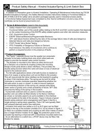
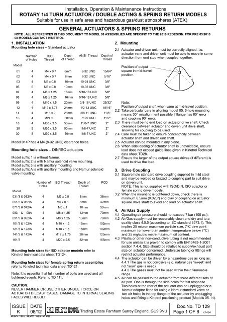
<strong>Installation</strong>, Operation & Maintenance Instructions<br />
ROTARY 1/4 TURN ACTUATOR / DOUBLE ACTING & SPRING RETURN MODELS<br />
Suitable for use in safe area and hazardous gas/dust atmospheres (ATEX)<br />
1. INSTALLATION<br />
Mounting hole sizes – Standard actuator<br />
Number<br />
of Holes<br />
ISO<br />
Thread<br />
GENERAL ACTUATORS & SPRING RETURNS<br />
NOTE : ALL REFERENCES IN THIS DOCUMENT TO MODEL 08 ASSEMBLIES ARE SPECIFIC TO THE 2010 REDESIGN. FOR PRE 05/2010<br />
08 MODELS CONTACT KINETROL.<br />
Model<br />
Depth<br />
of Thread<br />
ANSI Thread<br />
Depth of<br />
Thread<br />
01 4 M4 x 0.7 6mm 8-32 UNC 15/64"<br />
02 4 M4 x 0.7 8mm 8-32 UNC 5/16"<br />
03 4 M5 x 0.8 10mm 10-24 UNC 3/8"<br />
05 6 M5 x 0.8 10mm 10-32 UNC 3/8"<br />
07 4 M8 x 1.25 16mm 5/16-18 UNC 5/8"<br />
08 4 M8 x 1.25 16mm 5/16-18 UNC 5/8"<br />
09 4 M10 x 1.5 20mm 3/8-16 UNC 25/32”<br />
12 4 M12 x 1.75 24mm 1/2-13 UNC 15/16"<br />
14 4 M16 x 2 28mm 5/8-11 UNC 11/8"<br />
16 4 M24 x 3 38mm 7/8-9 UNC 11/2"<br />
18 4 M30 x 3.5 50mm 11/8-7 UNC 2"<br />
20 8 M30 x 3.5 50mm 11/8-7 UNC 2"<br />
30 8 M30 x 3.5 50mm 11/8-7 UNC 2"<br />
Model 014P has 4 M4 (8-32 UNC) clearance holes.<br />
Mounting hole sizes – DIN/ISO actuators<br />
Model suffix 1 is without Namur.<br />
Model suffix 2 is with Namur solenoid valve mounting.<br />
Model suffix 3 is with ancillary mounting.<br />
Model suffix A is with ancillary mounting and Namur solenoid<br />
valve mounting.<br />
Model<br />
Number of<br />
Holes<br />
ISO Thread<br />
Depth of<br />
Thread<br />
PCD<br />
031/3 & 032/A 4 M5 x 0.8 8mm 36mm<br />
051/3 & 052/A 4 M5 x 0.8 8mm 42mm<br />
071/3 & 072/A 4 M6 x 1 10mm 50mm<br />
083 & 08A 4 M8 x 1.25 13mm 70mm<br />
091/3 & 092/A 4 M8 x 1.25 13mm 70mm<br />
101/3 & 102/A 4 M10 x 1.5 16mm 102mm<br />
121/3 & 122/A 4 M10 x 1.5 16mm 102mm<br />
141/3 & 142/A 4 M12 x 1.75 20mm 125mm<br />
161/3 4 M20 x 2.5 32mm 165mm<br />
Mounting hole sizes for ISO adaptor models refer to<br />
<strong>Kinetrol</strong> technical data sheet TD124.<br />
Mounting hole sizes for female spring return assemblies<br />
refer to <strong>Kinetrol</strong> technical data sheet TD121.<br />
Note: It is essential that full number of bolts are used and all<br />
tightened evenly. Refer to TD 111.<br />
CAUTION:<br />
NEVER HAMMER OR USE OTHER UNDUE FORCE ON<br />
ACTUATOR DIECAST CASES. DAMAGE TO INTERNAL SEALING<br />
FACES WILL RESULT.<br />
2. Mounting<br />
2.1 Actuator and driven unit must be correctly aligned, i.e.<br />
actuator vane and driven unit must be able to move in same<br />
direction from end stop when coupled together.<br />
Position of output<br />
square in mid-travel<br />
position.<br />
Note:<br />
Position of output shaft when vane at mid-travel position.<br />
2.2 Take particular care in aligning model 05. 6-hole mounting<br />
means 30° misalignment possible if flange has 60° error<br />
and coupling 90° error.<br />
2.3 There must be no end load on actuator drive shaft. Check<br />
clearance between actuator and driven unit drive shaft,<br />
allowing for coupling to be used.<br />
2.4 Care must be taken to ensure concentricity between<br />
actuator shaft and driven unit shaft.<br />
2.5 Actuator can be mounted in any plane.<br />
2.6 When side loading of actuator shaft is unavoidable, ensure<br />
load does not exceed guide lines given in <strong>Kinetrol</strong> Technical<br />
data sheet TD28.<br />
2.7 Ensure the larger of the output square drives (if different) is<br />
used to drive the load.<br />
3. Drive Coupling<br />
3.1 Square hole standard drive coupling supplied in mild steel<br />
and may be welded or brazed to coupling part to suit drive<br />
on driven unit.<br />
NOTE: This is not supplied with ISO/DIN, ISO adaptor or<br />
female spring drive models.<br />
3.2 When the mounting is tightened down, check there is<br />
minimum 0.5mm (0.020") end play of coupling on actuator<br />
square drive shaft to avoid end load on actuator shaft.<br />
4. Air/Gas Supply<br />
4.1 Operating air pressure should not exceed 7 bar (100 psi).<br />
4.2 Air/Gas supply must be reasonably clean and dry and to a<br />
quality class 4.5.5 (according to ISO standard 8573.1). This<br />
implies 25 micron maximum particle size, 7°C dew point<br />
maximum (or lower than ambient temperature below 7°C)<br />
and 25 mg/cubic metre maximum oil content.<br />
4.3 Plastic or other non-conductive tubing is not recommended<br />
for use unless it is proven to comply with EN13463-1-2001<br />
section 7.4.4. Size should be relative to supply/exhaust port<br />
size on actuator concerned. Undersize tubing or fittings will<br />
restrict actuator performance.<br />
4.4 The actuator can be driven by a hazardous gas as long as:<br />
4.4.1 The gas is not corrosive (e.g. natural gas “sweet” and<br />
not “sour” gas is used).<br />
4.4.2 The gases must not be used within their flammable<br />
range.<br />
4.5 Air can be passed to the actuator from three different sets of<br />
air port. One is through the side holes for fast response.<br />
Two holes at the rear of the actuator can be unplugged or a<br />
Namur adaptor fitted for using a Namur standard valve or<br />
two air holes in the top flange of the actuator by unplugging<br />
holes and fitting a <strong>Kinetrol</strong> positioning product (Models 05-14).<br />
ISSUE<br />
K<br />
DATE<br />
08/12 Trading Estate Farnham Surrey England. GU9 9NU<br />
AR 5474 / ISS.J - AR 4777 / ISS.H - AR 4726<br />
Doc.No. TD 129<br />
Page 1 OF 8 KF464
<strong>Installation</strong>, Operation & Maintenance Instructions<br />
ROTARY 1/4 TURN ACTUATOR / DOUBLE ACTING & SPRING RETURN MODELS<br />
Suitable for use in safe area and hazardous gas/dust atmospheres (ATEX)<br />
5. Operation<br />
5.1 External stops are strongly recommended when actuator is<br />
operating a mechanism with cantilevered load. However,<br />
<strong>Kinetrol</strong> technical data sheet, TD37, can be used to ensure<br />
load inertia and travel speed remain within allowable limits.<br />
5.2 Second square end of drive shaft may be used for visual<br />
position indication, emergency manual operation or driving of<br />
add-on units (positioner, limit switch unit, etc.).<br />
5.3 If the square sizes are the same both ends spring units can be<br />
fitted either end. However, if they are different, always fit the<br />
spring to the larger square end and drive through this end only.<br />
5.4 Ambient operating temperature range of actuator is -20°C to<br />
80°C. This range may be extended to +100°C with Viton<br />
seals. Special care should be taken to ensure that heat<br />
conducted from, for example, a hot valve, does not increase<br />
the actuator temperature above these limits. Refer to <strong>Kinetrol</strong><br />
technical data sheet TD69 for guidance. A low temperature<br />
version of the actuator, having an ‘L’ at the end of the type<br />
code allows the unit to be used at an ambient temperature<br />
range of -40°C to 70°C, such actuators may be labelled with<br />
a special ATEX label (see section 8).<br />
5.5 Visual position indicators are available. Coloured red, made<br />
from Nylon 6, they can be fitted over square shaft at top of<br />
actuator or top of add-on unit.<br />
5.6 Ensure environmental conditions, such as corrosive<br />
environments, are compatible with the materials of<br />
construction and protective finishes (<strong>Kinetrol</strong> technical data<br />
sheet TD14 refers). If unsure contact <strong>Kinetrol</strong>. Excessive<br />
corrosion of the actuator may cause it to fail in service.<br />
5.7 Ensure operating speeds are less than 1 m/s for Cat 1<br />
atmospheres and 4m/s for cat 2 atmospheres, see table<br />
below for maximum operating travel times:<br />
5.8 Ensure any build up of dust is removed and regular checks are<br />
made.<br />
Model<br />
Category 1<br />
operating time<br />
for 90° travel<br />
(sec)<br />
Category 2<br />
operating time<br />
for 90° travel<br />
(sec)<br />
01 0.056 0.014<br />
02 0.067 0.017<br />
03 0.085 0.021<br />
05 0.107 0.027<br />
07 0.143 0.036<br />
08 N/A 0.042<br />
09 N/A 0.046<br />
10 N/A 0.047<br />
12 N/A 0.060<br />
14 N/A 0.081<br />
16 N/A 0.415<br />
18 N/A 0.545<br />
20/30 N/A 0.540<br />
6. Maintenance<br />
Maintenance is limited to replacement of seals when wear<br />
affects actuator performance. Seal life will vary according to<br />
application, conditions of cycle frequency, temperature,<br />
condition of air supply, etc. Detailed seal replacement<br />
instructions in next section.<br />
7. Recommended Spare Parts (Refer to pages 5 - 8)<br />
Standard seal kits, available for each actuator model, consist<br />
of the following:<br />
- 2 off vane seal - 2 off expander - 2 off shaft seal<br />
- Plus all necessary O-rings, screws, nuts and grease for<br />
all sizes up to model 14.<br />
In addition, a tube of sealant will be required to seal case<br />
halves. Spring return units are not user servicable and<br />
therefore no spare parts are available other than complete<br />
units and keeper plates for safe spring removal.<br />
8. Labelling (ATEX)<br />
All <strong>Kinetrol</strong> actuators that are approved for use in areas<br />
where explosives, dust & gases are present, are marked<br />
with one of the following labels:<br />
TYPE: XXX-XXX<br />
Serial No. xxxxxxxx<br />
Baseefa 03 ATEX 0443X<br />
II 1GD c 90°C -20°C Ta 80°C<br />
Category 1 Standard<br />
TYPE: XXX-XXX<br />
Serial No. xxxxxxxx<br />
Tech File KTR118 ATEX<br />
II 2GD c 90°C -20°C Ta 80°C<br />
Category 2 Standard<br />
TYPE: XXX-XXX L<br />
Serial No. xxxxxxxx<br />
Tech. File KTR118 ATEX<br />
II 2GD c 80°C -40°C Ta 70°C<br />
Low Temperature Label<br />
TYPE: XXX-XXX-2100<br />
Serial No. xxxxxxxx<br />
Baseefa 03 ATEX 0443X<br />
II 1GD c 110°C -20°C Ta 100°C<br />
Category 1 Viton<br />
TYPE: XXX-XXX-2100<br />
Serial No. xxxxxxxx<br />
Tech File KTR118 ATEX<br />
II 2GD c 110°C -20°C Ta 100°C<br />
Category 2 Viton<br />
Ensure that the details on the label such as the ambient<br />
temperature range is suitable for the application.<br />
Also ensure that any other equipment fitted to the actuator<br />
(e.g. limit switch box or positioner) does not restrict the use<br />
within the parameters shown on the above labels. Certificate<br />
of Conformance, TD125, shows the category of approval<br />
for different sizes of actuator and spring unit.<br />
9. Adjustment<br />
9.1 Stroke Adjustment – only applies to models with adjustable<br />
stops.<br />
Table of standard stroke<br />
adjustments available<br />
Adjustment range available<br />
Models Each stop<br />
03/07/08/09/16/18/20/30 10º<br />
02/05/14 8º<br />
01A/10/12 11º<br />
Greater adjustment range possible with non-standard stop<br />
screws. Contact KINETROL for details.<br />
9.2 Speed Adjustment<br />
Slower operation of actuator is possible, without significant<br />
torque output reduction, by external fitment of flow regulator<br />
valves.<br />
Faster operation can be achieved under certain conditions<br />
by fitting quick exhaust valves. For full details contact<br />
<strong>Kinetrol</strong>.<br />
ISSUE<br />
K<br />
DATE<br />
08/12 Trading Estate Farnham Surrey England. GU9 9NU<br />
AR 5474 / ISS.J - AR 4777 / ISS.H - AR 4726<br />
Doc.No. TD 129<br />
Page 2 OF 8 KF464
<strong>Installation</strong>, Operation & Maintenance Instructions<br />
ROTARY 1/4 TURN ACTUATOR / DOUBLE ACTING & SPRING RETURN MODELS<br />
Suitable for use in safe area and hazardous gas/dust atmospheres (ATEX)<br />
ACTUATOR SEAL REPLACEMENT INSTRUCTIONS<br />
1. DISMANTLING ACTUATOR (see exploded drawing/parts<br />
list) CAUTION: Before dismantling, check there are no burrs on<br />
square drive shafts. If there are, remove to avoid damage to<br />
bearings and shaft seals during removal of case halves. In the<br />
case of spring return actuators, remove spring unit (according<br />
to following section) before opening actuator case.<br />
FOR DISMANTLING/RE-ASSEMBLY INSTRUCTIONS FOR<br />
20/30 SIZE ACTUATOR REFER TO KINETROL TECHNICAL<br />
DATA SHEET TD104.<br />
2.10 After checking that expander and seal are right way round -<br />
expander has vane shaped hole, seal has shaft centre line<br />
marked - thread first few threads of each bolt into vane.<br />
2.11 While holding up side plate, expander and seal, apply a low<br />
strength anaerobic adhesive to bolt thread.<br />
2.12 Screw bolts down and tighten to torques given below.<br />
2.13 Turn vane over then fit seal, expander and side plate over<br />
end of bolts. Check orientation as before.<br />
2.14 Screw nuts down thread.<br />
1.1 All models: loosen, but do not remove, all case screws.<br />
1.2 Separate case halves by connecting air line to inlet port and<br />
blowing them apart. Procedure is safe although producing a<br />
2.15 Position vane assembly in coupling on bench, hold head of<br />
bolt with a spanner, torque up nut to torque specified<br />
in section 2.7.<br />
“bang”. Pull off one case half.<br />
Hex Head Bolts<br />
CAUTION: Do NOT hammer diecast castings or shaft end.<br />
It will damage internal sealing surfaces.<br />
01 6lbf./ins 0.07 m kg<br />
1.3 Clean both case halves removing silicone rubber sealant.<br />
07 8lbf./ins 0.09 m kg<br />
Clean joint surfaces of case flange with surgical spirit.<br />
08 10lbf./ins 0.12 m kg<br />
1.4 Replace and lubricate shaft seals.<br />
1.5 Undo vane nuts and bolts (if fitted) and remove old expanders<br />
09 10lbf./ins 0.12 m kg<br />
and seals from vane. Take care not to damage side plates.<br />
Clean vane.Some later models use nuts on one side of vane<br />
with bolts on other side.<br />
10<br />
12<br />
15lbf./ins<br />
30lbf./ins<br />
0.17 m kg<br />
0.35 m kg<br />
2. REASSEMBLY VANE<br />
Vane sub assembly with studs<br />
2.1 Check studs are tight through vane and equal length each<br />
side (if studs are fitted). If not, apply Loctite to thread and<br />
relocate correctly in vane.<br />
2.2 Model 18: Apply SILASTIC 732 RTV sealant around bottom<br />
of studs (to prevent air leakage through seal on vane stud<br />
holes).<br />
2.3 Fit new seal over studs after checking profile matches vane<br />
profile.<br />
2.4 Fit seal expander – the hole in it shaped like vane outline<br />
shows correct way round – teeth pointing away from vane.<br />
2.5 Fit side plate over studs.<br />
2.6 Fit new nuts to studs after applying Loctite medium strength<br />
sealant to threads.<br />
2.7 Tighten nuts to following torques:<br />
01 6 lbf.ins 0.07 m kg<br />
02 6 lbf.ins 0.07 m kg<br />
03 6 lbf.ins 0.07 m kg<br />
05 8 lbf.ins 0.09 m kg<br />
07 8 lbf.ins 0.09 m kg<br />
08 20 lbf.ins 0.23 m kg<br />
09 20 lbf.ins 0.23 m kg<br />
10 20 lbf.ins 0.23 m kg<br />
12 30 lbf.ins 0.35 m kg<br />
14 30 lbf.ins 0.35 m kg<br />
16 60 lbf.ins 0.69 m kg<br />
18 60 lbf.ins 0.69 m kg<br />
Vane sub assembly with hex head bolts<br />
2.8 Check vane for any obvious defects and make sure it is free<br />
of burrs, then place vane in cradle and place face down an a<br />
bench or hold in a vice.<br />
2.9 Push hex headed bolts with plain washer through side plate,<br />
expander (teeth facing towards head of bolt) and seal (base<br />
of seal away from bolt head).<br />
ISSUE<br />
K<br />
3. RE-ASSEMBLING ACTUATOR<br />
3.1 Coat bearing bushes and inside both case halves with<br />
molybdenum disulphide grease or grease supplied by<br />
KINETROL.<br />
3.2 Lightly and evenly coat joint face on each case half with<br />
INSTANT GASKET sealant (up to Model 14) available from<br />
<strong>Kinetrol</strong> (SP057) or Loctite, or SILASTIC 732 RTV sealant<br />
(Model 16 up) obtainable from ironmongers, etc. may be<br />
used as a substitute. CAUTION: EXCESS SEALANT, if<br />
extruded inside case, WILL IMPAIR OPERATION OF<br />
SEALS. Remove all excess sealant especially from inside<br />
edge.<br />
3.3 Insert vane into one case half, turning it to ease square on<br />
drive shaft through shaft seal. Watch that lip seals at ends<br />
of vane easily work down into case without damage.<br />
3.4 Fit remaining case half on top of the other, turning it to ease<br />
square through shaft seal.<br />
3.5 CAUTION: Check that lip seals are not trapped at case joint<br />
face when Viton seals are fitted. Ensure minimal time delay<br />
to closing of case once sealant has been applied<br />
3.6 Tighten case screws to the following torques:<br />
01 10 lbf.ins. 0.12 m kg<br />
02 10 lbf.ins. 0.12 m kg<br />
03 10 lbf.ins. 0.12 m kg<br />
05 20 lbf.ins. 0.23 m kg<br />
07 24 lbf.ins. 0.27 m kg<br />
08 60 lbf.ins. 0.7 m kg<br />
09 60 lbf.ins. 0.7 m kg<br />
10 80 lbf.ins. 0.9 m kg<br />
12 100 lbf.ins. 1.2 m kg<br />
14 120 lbf.ins. 1.4 m kg<br />
16 860 lbf.ins. 10 m kg<br />
18 1140 lbf.ins. 13 m kg<br />
3.7 Rotate vane manually to check movement and wipe away<br />
sealant extruded internally.<br />
3.8 Allow setting time for sealant before applying test air<br />
pressure.<br />
DATE<br />
08/12 Trading Estate Farnham Surrey England. GU9 9NU<br />
AR 5474 / ISS.J - AR 4777 / ISS.H - AR 4726<br />
Doc.No. TD 129<br />
Page 3 OF 8 KF464
<strong>Installation</strong>, Operation & Maintenance Instructions<br />
ROTARY 1/4 TURN ACTUATOR / DOUBLE ACTING & SPRING RETURN MODELS<br />
Suitable for use in safe area and hazardous gas/dust atmospheres (ATEX)<br />
SPRING RETURN UNITS<br />
NOTE : ALL REFERENCES IN THIS DOCUMENT TO MODEL 08 ASSEMBLIES ARE SPECIFIC TO THE 2010 REDESIGN. FOR PRE 05/2010<br />
08 MODELS CONTACT KINETROL.<br />
1. REMOVAL OF SPRING RETURN UNIT<br />
WARNING – the wound-up steel springs are storing a large<br />
amount of energy which, if suddenly released, can be<br />
dangerous.<br />
Keeper Plate<br />
pressure until balanced.<br />
2.7 Remove keeper plate completely.<br />
2.8 Disconnect air supply.<br />
Square<br />
Spring Housing<br />
Shaft Seal<br />
Base Plate<br />
Base Plate Screw<br />
O Ring Seal<br />
(08 only)<br />
Spring<br />
Holding Screws<br />
O Ring Seal<br />
Gasket<br />
(O ring on 08)<br />
Inlet Port<br />
Actuator<br />
1.1 A keeper plate strong enough to take full spring torque must<br />
be fitted in order to remove S/R unit without releasing spring<br />
tension.<br />
Note: Keeper plates and screws available from KINETROL.<br />
Refer to table on page 5 for spare part order Numbers.<br />
1.2 Connect air line via pressure regulating valve to actuator air<br />
inlet.<br />
1.3 Place keeper plate over square shaft protruding from S/R<br />
unit. Keeper plates with male squares can be provided for<br />
female drive spring packs.<br />
1.4 Increase air pressure slowly until actuator vane turns to<br />
mid-travel position. (See sketch at 2 of ACTUATOR section.)<br />
Keeper plate holes will then line up with threaded holes in<br />
spring housing.<br />
1.5 Insert all screws through keeper plate holes and tighten to<br />
lock keeper plate in position. Disconnect air supply.<br />
1.6 Separate spring housing from base plate by removing holding<br />
screws. Then remove spring housing.<br />
1.7 If necessary to gain access to actuator screws also remove<br />
base plate by removing screws. Take care with gasket/o ring<br />
between base plate and actuator. (Service actuator as<br />
required per Seal Replacement Instructions).<br />
2. REASSEMBLY OF SPRING RETURN UNIT<br />
2.1 If necessary replace base plate after replacing gasket (o ring<br />
on 08 models only). Ensure the 4 countersunk baseplate fixing<br />
screws are all fitted with o rings (08 models only).<br />
2.2 Ensure actuator vane is in mid-travel position.<br />
2.3 Locate spring housing on shaft, (if the actuator square size<br />
is different on one end ensure spring is fitted to correct drive<br />
end) rotate it to line up holding screw holes with base plate<br />
and replace holding screws.<br />
2.4 Connect air supply (as in 1.2) to actuator inlet port.<br />
2.5 Adjust air pressure until it balances the spring tension.<br />
2.6 Loosen keeper plate screws. If air pressure correctly<br />
balancing spring tension will not bind. If binding, adjust air.<br />
ISSUE<br />
K<br />
3. ADJUSTMENT SPRING TENSION<br />
WARNING: The wound-up steel springs are storing a large<br />
amount of energy which, if suddenly released, can be<br />
dangerous.<br />
3.1 Tension Setting Definitions<br />
3.1.1 Optimum setting is when S/R unit is able to provide as<br />
much output torque on the spring return stroke as that<br />
produced by the corresponding air stroke at a particular air<br />
supply pressure.<br />
3.1.2 Differential setting is when S/R unit produces more or<br />
less output torque on spring return stroke as that produced by<br />
the corresponding air stroke at a particular air supply<br />
pressure.<br />
3.1.3 Operating air pressure in these instructions means the<br />
actual air supply pressure at which the actuator will be<br />
operated.<br />
3.2 Optimum Spring Setting Test<br />
3.2.1 Detach actuator/spring return from valve or mechanism<br />
operated by them.<br />
3.2.2 Attach air supply to actuator through pressure<br />
regulating valve and gauge with supply shut off at regulator.<br />
3.2.3 Gradually open regulator to increase air supply to<br />
actuator until actuator output shaft just begins to move.<br />
3.2.4 Note actual pressure at which actuator output shaft<br />
moved.<br />
3.2.5 If actual pressure noted at 3.2.4 is about half the<br />
operating air pressure then spring tension is at optimum.<br />
If actual pressure noted at 3.2.4 is significantly less then half<br />
operating air pressure then spring tension is below optimum,<br />
i.e. output torque on S/R stroke will be less than that produced<br />
on corresponding air stroke at operating air pressure.<br />
DATE<br />
08/12 Trading Estate Farnham Surrey England. GU9 9NU<br />
AR 5474 / ISS.J - AR 4777 / ISS.H - AR 4726<br />
Doc.No. TD 129<br />
Page 4 OF 8 KF464
<strong>Installation</strong>, Operation & Maintenance Instructions<br />
ROTARY 1/4 TURN ACTUATOR / DOUBLE ACTING & SPRING RETURN MODELS<br />
Suitable for use in safe area and hazardous gas/dust atmospheres (ATEX)<br />
Conversely if actual pressure at 3.2.4 is significantly greater<br />
than half operating pressure then spring tension is above the<br />
optimum, i.e. S/R torque will be greater than air stroke torque.<br />
3.3 Tension Adjustment Method (Standard S/R units without<br />
worm drive)<br />
3.3.1 Equipment/facilities required:<br />
Air supply with pressure regulator valve and gauge in line.<br />
Keeper plate with bolts and spacers (KINETROL supply).<br />
Spanner/tools to suit.<br />
Means of securely fixing assembly to a suitable work bench.<br />
3.3.2 Detach actuator/spring return from valve/mechanism.<br />
3.3.3 Connect air supply to actuator with regulator shut off.<br />
3.3.4 Carry out optimum spring setting test as at 2.2 above to<br />
determine whether spring tension needs to be increased or<br />
decreased.<br />
3.3.5 Gradually open air supply regulator until actuator vane<br />
is at centre of travel (45°) position (see sketch at page 1).<br />
3.3.6 Place keeper plate over S/R square shaft at top of S/R<br />
unit.<br />
CAUTION: If keeper plate of flat type, spacer washers at<br />
least 3mm (1/8") thick must be used under keeper plate.<br />
KINETROL die cast keeper plates do not need spacer<br />
washers.<br />
3.3.7 If bolt holes of keeper plate do not line up with<br />
corresponding tapped holes in S/R unit, carefully open or<br />
close air supply regulator until S/R square shaft turns so that<br />
holes do line up.<br />
3.3.8 Insert and tighten keeper plate bolts.<br />
3.3.9 Shut off air supply to actuator.<br />
3.3.10 Undo and remove all spring housing flange bolts.<br />
Leave spring housing resting on base plate.<br />
3.3.11 Turn spring housing in required direction according to:<br />
a) S/R operating direction, i.e. clockwise or<br />
anticlockwise operation of spring force, and<br />
b) Tension required to be increased or<br />
decreased.<br />
NOTE: Larger sizes of actuator/spring return will require<br />
spanner and possibly extension bar to turn spring housing<br />
through square shaft on S/R unit.<br />
3.3.12 Dependent on the age of S/R unit concerned there will<br />
be 12 or 24 bolt holes around the base plate flange (except<br />
for 014 and 08 models which have only 4, and 144 model which<br />
now has 36).<br />
Therefore older models (12 holes) can only be adjusted by<br />
30° steps, whereas new models can be adjusted by 15° steps<br />
(014 and 08 by 90° steps and current 144 by 10° steps).<br />
3.3.13 As a rough guide 30° adjustment of spring housing<br />
relative to base plate will give 8% change of spring torque<br />
output providing spring is already tensioned within its<br />
operating air pressure range, i.e. standard S/R units between<br />
50 and 80 p.s.i. Low air supply S/R units between 25 and 50<br />
p.s.i. See catalogue for full details.<br />
3.3.14 Maximum adjustment in one step will be 45° controlled<br />
by available vane movement in actuator.<br />
3.3.15 After turning spring housing by amount required (or<br />
possible) line up bolt holes in spring housing and base plate<br />
flanges. Insert flange bolts and tighten nuts.<br />
3.3.16 Carefully open air supply to actuator until side load on<br />
keeper plate bolts is relieved.<br />
3.3.17 Remove keeper plate.<br />
3.3.18 Repeat optimum spring setting test as at 4.2 above.<br />
3.3.19 If necessary, repeat operations 4.3.5 to 4.3.17 to<br />
further increase or decrease spring tension.<br />
WARNING: Spring tension must not be further increased if<br />
air pressure noted at 4.2.4 is 40 p.s.i. or more for standard<br />
S/R units or 30 p.s.i. for special low air supply types.<br />
Note: If alignment of mounting holes to square is important,<br />
then the spring tension should only be moved in 90°<br />
increments. This is especially important with female drive<br />
spring units where the mounting angle to the valve will<br />
determine correct opening/closing of valve.<br />
4. LABELLING (ATEX)<br />
All spring units that are suitable for use in explosive areas<br />
are labelled with one of the labels as shown in 8 in actuator<br />
section above.<br />
Ensure that the details on the label such as the ambient<br />
temperature range is suitable for the application.<br />
Also ensure that any other equipment fitted to the spring<br />
return (e.g. limit switch box or positioner) does not restrict<br />
the use within the parameters shown on the above labels.<br />
Certificate of Conformance, TD125, shows the category of<br />
spring return approval for different sizes of spring units.<br />
5. SPARE PART ORDER CODES – KEEPER PLATES:<br />
SPRING<br />
SIZE<br />
MALE DRIVE FEMALE ISO<br />
DRIVE<br />
FEMALE SERRATED<br />
DRIVE<br />
01 SP 350 N/A N/A<br />
02 SP 351 N/A N/A<br />
03 SP 352 SP 1360/1 N/A<br />
05 SP 353 SP 1362/3 SP 1480<br />
07 SP 354 SP 1364 SP 1481<br />
08 SP 904 SP 1378 SP 1483<br />
09 SP 356 SP 1365 SP 1482<br />
10 SP 359 SP 1366 SP 1482<br />
12 SP 357 SP 1368 SP 1370 N/A<br />
14 SP 358 SP 1371 N/A<br />
16 SP 360 SP 1372 N/A<br />
18 SP 361 SP 1373 N/A<br />
20 SP 362 SP 1374 N/A<br />
30 SP 362 N/A N/A<br />
For non-standard spring codes please contact <strong>Kinetrol</strong>.<br />
ISSUE<br />
K<br />
DATE<br />
08/12 Trading Estate Farnham Surrey England. GU9 9NU<br />
AR 5474 / ISS.J - AR 4777 / ISS.H - AR 4726<br />
Doc.No. TD 129<br />
Page 5 OF 8 KF464
<strong>Installation</strong>, Operation & Maintenance Instructions<br />
ROTARY 1/4 TURN ACTUATOR / DOUBLE ACTING & SPRING RETURN MODELS<br />
Suitable for use in safe area and hazardous gas/dust atmospheres (ATEX)<br />
6<br />
CASE<br />
EXPLODED VIEW OF A TYPICAL STANDARD ACTUATOR<br />
AIR PORT SEALING SCREWS<br />
SP 638 NAMUR ADAPTOR KIT<br />
3<br />
2<br />
SHAFT SEAL<br />
1<br />
DOWEL PIN<br />
BUSH<br />
STANDARD VANE<br />
VANE SEAL<br />
EXPANDER<br />
SIDE PLATE<br />
3<br />
CASE FIXINGS<br />
VANE FIXINGS<br />
5<br />
4<br />
ISSUE<br />
K<br />
DATE<br />
08/12 Trading Estate Farnham Surrey England. GU9 9NU<br />
AR 5474 / ISS.J - AR 4777 / ISS.H - AR 4726<br />
Doc.No. TD 129<br />
Page 6 OF 8 KF464
<strong>Installation</strong>, Operation & Maintenance Instructions<br />
ROTARY 1/4 TURN ACTUATOR / DOUBLE ACTING & SPRING RETURN MODELS<br />
Suitable for use in safe area and hazardous gas/dust atmospheres (ATEX)<br />
6<br />
EXPLODED VIEW OF A TYPICAL ISO/DIN ACTUATOR<br />
2<br />
AIR PORT SEALING SCREWS<br />
SP 638<br />
NAMUR ADAPTOR KIT<br />
CASE<br />
3<br />
1<br />
VANE FIXINGS<br />
1<br />
BUSH<br />
DIN/ISO VANE<br />
SHAFT SEAL<br />
VANE SEAL<br />
DOWEL PIN<br />
EXPANDER<br />
SIDE PLATE<br />
DIN CASE<br />
SHAFT ORING<br />
CASE FIXINGS<br />
3<br />
4<br />
1<br />
THRUST WASHER<br />
1<br />
BUSH<br />
COUPLING<br />
COUPLING ORING<br />
DIN/ISO FLANGE<br />
FLANGE SCREWS<br />
ISSUE<br />
K<br />
DATE<br />
08/12 Trading Estate Farnham Surrey England. GU9 9NU<br />
AR 5474 / ISS.J - AR 4777 / ISS.H - AR 4726<br />
Doc.No. TD 129<br />
Page 7 OF 8 KF464
<strong>Installation</strong>, Operation & Maintenance Instructions<br />
ROTARY 1/4 TURN ACTUATOR / DOUBLE ACTING & SPRING RETURN MODELS<br />
Suitable for use in safe area and hazardous gas/dust atmospheres (ATEX)<br />
SPARE PART ORDERING CODES<br />
NOTE : ALL REFERENCES IN THIS DOCUMENT TO MODEL 08 ASSEMBLIES ARE SPECIFIC TO THE 2010 REDESIGN. FOR PRE 05/2010<br />
08 MODELS CONTACT KINETROL.<br />
SPARE PART ORDERING CODES FOR STANDARD ACTUATOR<br />
ITEM DESCRIPTION QTY SPARE NO'S FOR ACTUATORS<br />
NO. 0M0 014 024 034/B 054/B 074/B 084/B 094/B 124/B 144/B 164 184 204 304<br />
1 Seal Kit 1 SP055 SP871 SP041 SP054 SP042 SP043 SP900 SP045 SP046 SP047 SP053 SP048 SP051 SP052<br />
2 Vane assembly 1 SP081 SP872 SP091 SP471 SP121 SP151 SP901 SP212 SP262 SP278 SP371 SP311 SP400 -<br />
3 Case assembly Matched Pair SP083 SP873 SP099 SP479 SP129 SP159 SP902 SP221 SP253 SP283 SP379 SP319 SP399 -<br />
4 Stop assembly 2 - SP874 SP104 SP485 SP138 SP165 SP905 SP227 SP260 SP292 SP384 SP324 SP396 SP396<br />
5 Coupling 1 - SP074 SP106 SP487 SP140 SP167 SP903 SP229 SP264 SP298 SP386 SP326 SP406 SP406<br />
6 Indicator assembly 1 - - SP108 SP489 SP146 SP171 SP171 SP171 SP171 SP171 - - - -<br />
Namur adaptor 1 - - - SP638 - - - -<br />
ITEM DESCRIPTION<br />
NO.<br />
2 Standard Vane<br />
assembly<br />
3 Standard Case<br />
assembly<br />
VARIATIONS FOR OLD STYLE ACTUATOR PARTS<br />
QTY. SPARE NO'S FOR ACTUATORS<br />
0M0 010 010A 020 030 050 070 080 090 120 140 160 180 200 300<br />
1 SP081 SP061 SP331 SP091 SP471 SP121 SP151 SP211 SP241 SP271 SP371 SP311 SP400 -<br />
Matched Pair SP083 SP069 SP338 SP099 SP479 SP129 SP159 SP221 SP253 SP283 SP379 SP319 SP399 -<br />
6 Indicator assembly 1 - - - SP108 SP489 SP146 SP171 - SP231 SP267 SP301 - - - -<br />
*<br />
CONTACT KINETROL<br />
*<br />
*<br />
For actuators built to 'ANSI' standard (e.g. 057-100) change spare part number prefix<br />
from 'SP' to 'ASP' (e.g. for actuator 057-100 item 2 becomes ASP142<br />
or for 059-100 item 2 becomes ASP121).<br />
SPARE PART ORDERING CODES FOR ISO/DIN ACTUATOR<br />
ITEM<br />
NO.<br />
DESCRIPTION QTY. SPARE NO'S FOR ACTUATORS<br />
SPARE NO'S FOR ACTUATORS<br />
023/A 033/A 053/A 073/A 083/A 093/A 103/A 123/A 143/A 163/A<br />
1 Seal Kit 1 SP041 SP054 DSP042 DSP043 DSP900 DSP045 SP056 SP046 SP047 SP053<br />
2 Vane assembly 1 SP091 DSP472 DSP142 DSP169 DSP901 DSP212 DSP801 DSP262 DSP283 DSP371<br />
3 Case assembly Matched Pair SP099 DSP480 DSP130 DSP160 DSP902 DSP222 DSP811 DSP263 DSP294 DSP379<br />
4 Stop assembly 2 SP104 SP485 SP138 SP165 SP905 SP227 SP817 SP260 SP292 SP384<br />
6 Indicator assembly 1 SP108 SP489 SP146 SP171 SP171 SP171 SP171 SP171 SP171 -<br />
Namur adaptor - SP638 -<br />
#<br />
VARIATIONS FOR OLD STYLE ISO/DIN ACTUATOR PARTS<br />
ITEM<br />
NO.<br />
DESCRIPTION QTY. SPARE NO'S FOR ACTUATORS<br />
SPARE NO'S FOR ACTUATORS<br />
021 031 051 071 091 101 121 141 161<br />
2 Vane assembly 1 SP041 DSP471 DSP121 DSP151 DSP211 DSP800 DSP241 DSP271 DSP371<br />
3 Case assembly Matched Pair SP099 DSP479 DSP129 DSP159 DSP221 DSP811 DSP253 DSP283 DSP379<br />
6 Indicator assembly 1 SP108 SP489 SP146 SP171 SP231 DSP820 SP267 SP301 -<br />
ISSUE<br />
K<br />
DATE<br />
08/12 Trading Estate Farnham Surrey England. GU9 9NU<br />
AR 5474 / ISS.J - AR 4777 / ISS.H - AR 4726<br />
#<br />
NOTE SIZE 10 CASE /VANE CONSTRUCTION IS SIMILAR TO STANDARD ACTUATOR<br />
Doc.No. TD 129<br />
Page 8 OF 8 KF464