
You also want an ePaper? Increase the reach of your titles
YUMPU automatically turns print PDFs into web optimized ePapers that Google loves.
PRODUCT DATA SHEET<br />
<strong>ACTUATOR</strong><br />
<strong>LA27</strong><br />
Features:<br />
• 24V DC permanent magnet motor.<br />
• Thrust up to 8000N (in a push application)<br />
• Thrust up to 4000N (in a pull application)<br />
• Elegant and compact design with small<br />
installation dimensions<br />
• Protection class: IPX4, IPX6<br />
• Colour: Dark grey or light grey<br />
• Built-in end stop switches (not adjustable)<br />
• Possible to mount on control box CB6 with a<br />
special mounting clip (article no. 009271002 is<br />
delivered with CB6 )<br />
• Scratch and wear resistent powder painted<br />
steel inner tube.<br />
• Brake ensures the self-locking<br />
ability in either push or pull<br />
directions.There will always<br />
be a reduction of the selflock<br />
characteristic when the<br />
actuator is run in the opposite direction to the<br />
brake direction<br />
• Thrust up to 3500N in push with Quick Release<br />
• <strong>LA27</strong> with Quick Release can have ratchet spline<br />
it can only pull with max.100N (anti-squeeze).<br />
• <strong>LA27</strong> with QR can be combined with std. spline<br />
function, it can only push.<br />
• Compatible with CB9C (only with the versions AC,<br />
AD, AE or AH), CB6, CB6S OBL/OBF, CB6S OBM,<br />
CB16 OBL/OBF, CB20)<br />
• Noise level 50dB (A), actuator not loaded<br />
Usage:<br />
• Duty cycle: 2/18; 2 minutes continuous use<br />
followed by 18 minutes not in use<br />
• Duty cycle: Max 5% or 1 min. continuous use<br />
followed by 19 minutes not in use - with 8000N<br />
version.<br />
• Lifetime limited to only 3000 cycles according to<br />
EN1970 - with 8000N version<br />
• Ambient temperature: +5 o to +40 o C (the<br />
actuator must also be at this temp.)<br />
• <strong>LA27</strong> is approved according to EN 60601-1 /<br />
UL60601-1<br />
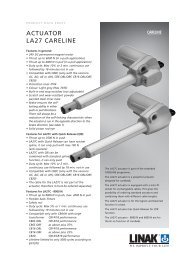
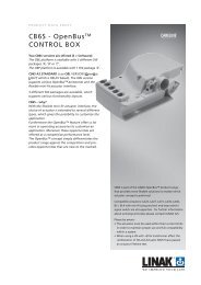
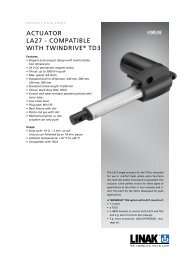
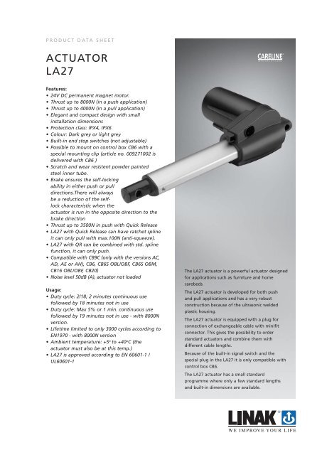
The <strong>LA27</strong> actuator is a powerful actuator designed<br />
for applications such as furniture and home<br />
carebeds.<br />
The <strong>LA27</strong> actuator is developed for both push<br />
and pull applications and has a very robust<br />
construction because of the ultrasonic welded<br />
plastic housing.<br />
The <strong>LA27</strong> actuator is equipped with a plug for<br />
connection of exchangeable cable with minifit<br />
connector. This gives the possibility to order<br />
standard actuators and combine them with<br />
different cable lengths.<br />
Because of the built-in signal switch and the<br />
special plug in the <strong>LA27</strong> it is only compatible with<br />
control box CB6.<br />
The <strong>LA27</strong> actuator has a small standard<br />
programme where only a few standard lengths<br />
and built-in dimensions are available.
....continous<br />
Usage:<br />
NOTE: re. <strong>LA27</strong> with 6.000N specification (274x3xxx1xxx0xZ; Z = A or B i.e with Bouverat worm axle*) for<br />
OpenBus:<br />
I.e. to use such combination a preceding test MUST be carried out.<br />
This combination reduces the self-lock ability because of lower friction from the Bouverat worm which has a<br />
rolled axle. The Bouverat worm is however needed because of the OpenBus output power.<br />
The alternative is a milled worm axle, but this may mean reduced lifetime of the worm.<br />
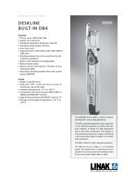
The problem related to an application:<br />
The self-lock ability may be reduced in cases where the load curve is 6.000N in both minimum and maximum<br />
stroke length - see (A). Further such load distribution may reduce the lifetime of actuator.<br />
A reduced load curve e.g. as in illustration (B) may also result in reduced self-lock, however it may have less<br />
impact on the lifetime of the actuator.<br />
Required test to ensure compatibility:<br />
(only needed for <strong>LA27</strong> with 6.000N for OpenBus (274x3xxx1xxx0xZ; Z = A or B))<br />
The purpose is:<br />
• to observe the actual load curve distribution (comparison to above curves). If load curve results are better<br />
than the above you can proceed. If in doubt about evaluating the load curves please contact your<br />
LINAK A/S sales engineer.<br />
• to observe the self-lock ability in the actual application. In fact the application design may support the<br />
self-lock ability in such a way so that <strong>LA27</strong> no longer sinks. Normally the actuator is not allowed to sink,<br />
however it is the customer who decides if it can be accepted (depends on the application type).<br />
• a lifetime test MUST be carried out by the LINAK Subsidiary or be documented by the customer to ensure<br />
that mutual expectations are met.<br />
I.e. All <strong>LA27</strong> with 6.000 N load specification (all 4 mm spindle types) MUST be tested as described before they<br />
can be accepted for running production. However samples for test are available.<br />
FOOTNOTE:<br />
* REMARK: Z as type ‘0’ does not use the Bouverat worm. However type ‘0’ is NOT compatible with the<br />
transformer used for OpenBus CB’s
Technical specifications<br />
Combi code<br />
Generel<br />
Max load<br />
Typical amp.<br />
Speed<br />
Selocking<br />
Type seleon<br />
Actuator type<br />
Spindle type<br />
Back xture<br />
Piston rod eye<br />
Opon posion<br />
Colour<br />
<br />
Brake<br />
Stroke Length<br />
Motor type<br />
IP Degree<br />
Motor PCBA<br />
PITCH<br />
MAX STROKE<br />
MIN STROKE<br />
PUSH<br />
PULL<br />
27 X X X X Z X X BBB Z Z Z<br />
27 1 F M 0 B Z 4 1 BBB Z Z Z 3 200 50 8000 2000 5,7 4,9 2,7 3,8 8000 push, 4000 pull X<br />
Max current at<br />
max load<br />
Average<br />
current at max<br />
load<br />
Minimum<br />
speed at max<br />
load<br />
Average speed,<br />
max load<br />
Short-circuit ON<br />
Std.<br />
8000N<br />
QR<br />
0 2000<br />
1<br />
0<br />
2000<br />
2<br />
-<br />
3<br />
27 2 S Z 0 B Z 0 BBB Z Z Z 5 300 50<br />
3.8 3.3 4,5 5,5<br />
1<br />
2<br />
3<br />
0<br />
1<br />
2<br />
3500<br />
-<br />
-<br />
3500<br />
27 2 F<br />
C E<br />
M<br />
C E<br />
F<br />
Z<br />
0<br />
1<br />
2<br />
3<br />
0<br />
1 BBB Z Z Z 5 250 50 3500 -<br />
750<br />
3.5 3.1 4,5 5,5<br />
27 3 S Z 0 B<br />
Z<br />
1<br />
2<br />
3<br />
0<br />
1<br />
2<br />
3<br />
1500 -<br />
0 2 - 1500<br />
0 3000<br />
1<br />
0<br />
3000<br />
2<br />
-<br />
3<br />
250<br />
0<br />
6000<br />
1<br />
1 -<br />
2<br />
27 4 S Z 0 B Z BBB Z Z Z 4 50<br />
5<br />
3<br />
0<br />
251<br />
1<br />
4000<br />
1<br />
-<br />
2<br />
300<br />
3<br />
-<br />
0<br />
1<br />
0<br />
2<br />
250 - 4000<br />
1000<br />
1<br />
0<br />
1000<br />
2<br />
-<br />
3<br />
27 7 S Z 0 B Z 0 BBB Z Z Z 6 300 50<br />
3,5<br />
1<br />
2<br />
3<br />
0<br />
1<br />
2<br />
2500<br />
-<br />
-<br />
2500<br />
C E<br />
0<br />
1<br />
27 7 F M Z 1 BBB Z Z Z 6<br />
C E 2<br />
250 50 2500 - 3,5<br />
F 3<br />
Z<br />
3,5 2,7 10 11<br />
4,6<br />
2,9<br />
3<br />
5<br />
3,4<br />
2,9 5 6,8<br />
6,8<br />
2000<br />
3500*<br />
3500*<br />
0 750 750<br />
-<br />
1<br />
BBB<br />
Z<br />
Z 9 405 50<br />
1500*<br />
3000<br />
6000*<br />
4000<br />
4000<br />
1000<br />
2500*<br />
2500*<br />
X<br />
X<br />
X<br />
X<br />
X<br />
X<br />
X<br />
X<br />
X<br />
X<br />
X<br />
X<br />
Z = No iuence on technical data<br />
X = Iuence on technical data<br />
S = Standard<br />
BBB = Look max stroke in table<br />
F = Flexible<br />
M = Massive/Solid<br />
* = See tabel 1 for selocking running opposite direon of brake direon<br />
Max BID (Build in Dimension) is 700 mm<br />
Spindle<br />
type<br />
Pitch<br />
(mm)<br />
3 9 1000<br />
4 4 2000<br />
7 6 1500<br />
2 5 -<br />
1 3 2000<br />
Max.<br />
self-lock (N)<br />
Table 1.<br />
Reduced self-lock characteristics when the<br />
actuator is run in the opposite direction.
Built-in Dimensions (standard)<br />
Standard<br />
S + 170 mm<br />
Standard + Mechanical Spline<br />
S + 170 mm<br />
Built-in Dimensions (Options)<br />
QR ver. 2 + ratchet<br />
spline<br />
QR ver. 2<br />
QR ver. 2 +<br />
mechanical spline<br />
8000 N<br />
S < 150 mm<br />
8000 N<br />
S > = 150 mm<br />
S + 180 mm S + 186 mm S + 186 mm S + 210 mm S + 260 mm<br />
The maximum allowed Built-in Dimension may not exceed the standard BID by more than 100 mm.<br />
Contact LINAK A/S if more than 100 mm is wanted.<br />
If mechanical spline and eye options 1, 3 or 4 are chosen, then the Built-in Dimension is increased by<br />
10 mm.<br />
“HALL” has no influence on the Built-in Dimensions.
<strong>LA27</strong><br />
Ordering example:<br />
2 7 0 4 0 1 0 0 0 0 0 3 B 4 - 2 1 2 0 1 0 2 7 0 1 D 0 0<br />
0 0<br />
Not used<br />
Not used<br />
Safety Factor:<br />
Cable:<br />
Plug Type:<br />
Fire Category:<br />
Install. Dim.:<br />
Brake:<br />
Option/Position:<br />
Piston Rod Eye:<br />
Back fixture:<br />
Colour:<br />
IP:<br />
Motor Type:<br />
Interface:<br />
0 = None<br />
0 = None<br />
0 = 2.0<br />
1 = 1.5<br />
2 = 2.5<br />
0 = None<br />
D = Mini-fit<br />
X = Special<br />
1 = V0<br />
2 = V2<br />
XXXX = mm<br />
0 = None<br />
1 = Brake PUSH<br />
2 = Brake PULL<br />
0 = None<br />
A = Internal QR<br />
K = High Load<br />
X = Other<br />
1 = With slot<br />
2 = Without slot<br />
X = Special<br />
1 = 0 degrees<br />
2 = 90 degrees<br />
X = Special<br />
2 = Grey RAL7035<br />
3 = Dark grey RAL7016<br />
X = Special<br />
-<br />
4 = IPX4<br />
6 = IPX6<br />
B = 24VDC. Normal<br />
X = Other<br />
Description<br />
01 = Analog<br />
02 = OpenBus<br />
XX = Special<br />
Positionering:<br />
Safety :<br />
Stroke Length:<br />
Spindle Pitch:<br />
Actuator Type:<br />
0 = None<br />
H = Hall<br />
X = Special<br />
0 = None<br />
A = Safety nut<br />
C = Mec.Spline<br />
D = Mec.Spline+Safety nut.<br />
J = Ratchet Spline<br />
K = Ratchet Spline + Safety nut<br />
X = Special<br />
XXX = mm.<br />
030 = 3 mm<br />
040 = 4 mm<br />
050 = 5 mm<br />
060 = 6 mm<br />
090 = 9 mm<br />
27 = <strong>LA27</strong><br />
It is possible to order <strong>LA27</strong> with individual stroke lengths (in steps of 5 mm) and installation dimensions. This<br />
requires a minimum quantity of 200 pcs per order.
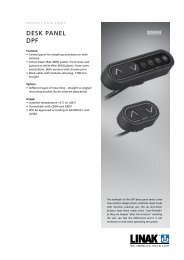
Dimensions <strong>LA27</strong><br />
Drawing no.:<strong>LA27</strong>001B<br />
Dimensions <strong>LA27</strong> with CB6:<br />
Drawing no.: CB6_<strong>LA27</strong>001B
Dimension for <strong>LA27</strong>C with Quick Release:<br />
Quick release unit<br />
Bowden cable<br />
10.2<br />
93.8<br />
35.2<br />
6.8<br />
15<br />
10.3<br />
28<br />
26<br />
38.7<br />
60.2<br />
19.1<br />
18<br />
15<br />
35.7<br />
125.5<br />
12.5<br />
92.4<br />
128.6<br />
18.9<br />
29.5<br />
25<br />
1.8<br />
Detail A<br />
5.3<br />
Detail A<br />
Drawing no.:277131-k1500041<br />
Dimension for <strong>LA27</strong>C with 8000 N:<br />
26<br />
25<br />
38<br />
28<br />
93.8<br />
35.2<br />
34.7<br />
15<br />
19.1<br />
92.4<br />
125.5<br />
12.5<br />
29.5<br />
10.3<br />
Cable<br />
128.6<br />
29<br />
7.5<br />
10.3±0.1<br />
1.5<br />
Drawing no. 0279020-10
Back fixtures:<br />
SECTION<br />
A-A<br />
A<br />
Type 06<br />
Type 05<br />
Type 01 Type 02<br />
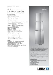
Current v’s Thrust (typical values) Push with push brake<br />
Speed v’s Thrust (typical values) Push with push brake<br />
Copyright © LINAK 2012.12 . MA M9-02-041-M . Chapter 5.4<br />
Terms of use<br />
The user is responsible for determining the suitability of LINAK products for specific application.<br />
LINAK takes great care in providing accurate and up-to-date information on its products.<br />
However, due to continuous development in order to improve its products, LINAK products are<br />
subject to frequent modifications and changes without prior notice. Therefore, LINAK cannot<br />
guarantee the correct and actual status of said information on its products.<br />
While LINAK uses its best efforts to fulfil orders, LINAK cannot, for the same reasons as<br />
mentioned above, guarantee the availability of any particular product. Therefore, LINAK reserves<br />
the right to discontinue the sale of any product displayed on its website or listed in its catalogues<br />
or other written material drawn up by LINAK.<br />
All sales are subject to the Standard Terms of Sale and Delivery for LINAK. For a copy hereof,<br />
please contact LINAK.<br />
FOR MOUNTING INSTRUCTIONS AND GUIDANCE IN USAGE, PLEASE SEE THE RELEVANT USER’S MANUALS