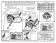
R1224 REGULATOR THEORY - Plane Power
R1224 REGULATOR THEORY - Plane Power
R1224 REGULATOR THEORY - Plane Power

Create successful ePaper yourself
Turn your PDF publications into a flip-book with our unique Google optimized e-Paper software.
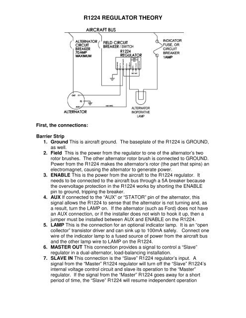
<strong>R1224</strong> <strong>REGULATOR</strong> <strong>THEORY</strong><br />
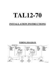
First, the connections:<br />
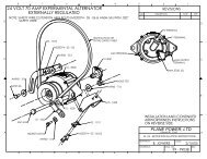
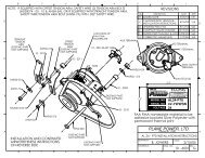
Barrier Strip<br />
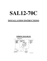
1. Ground This is aircraft ground. The baseplate of the <strong>R1224</strong> is GROUND,<br />
as well.<br />
2. Field This is the power from the regulator to one of the alternator’s two<br />
rotor brushes. The other alternator rotor brush is connected to GROUND.<br />
<strong>Power</strong> from the <strong>R1224</strong> makes the alternator’s rotor (the part that spins) an<br />
electromagnet, causing the alternator to generate power.<br />
3. ENABLE This is the power from the aircraft to the <strong>R1224</strong> regulator. It<br />
needs to be connected to the aircraft bus through a 5A breaker because<br />
the overvoltage protection in the <strong>R1224</strong> works by shorting the ENABLE<br />
pin to ground, tripping the breaker.<br />
4. AUX If connected to the “AUX” or “STATOR” pin of the alternator, this<br />
signal allows the <strong>R1224</strong> to sense that the alternator is not turning and, as<br />
a result, turn the LAMP on. If the alternator (such as Ford) does not have<br />
an AUX connection, or if the installer does not wish to hook it up, then a<br />
jumper must be installed between AUX and ENABLE on the <strong>R1224</strong>.<br />
5. LAMP This is the connection for an optional indicator lamp. It is an “open<br />
collector” transistor driver and can sink up to 100mA safely. Connect one<br />
wire of the indicator lamp to a fused source of power from the aircraft bus<br />
and the other lamp wire to LAMP on the <strong>R1224</strong>.<br />
6. MASTER OUT This connection provides a signal to control a “Slave”<br />
regulator in a dual-alternator, load-balancing installation.<br />
7. SLAVE IN This connection is the “Slave” <strong>R1224</strong> regulator’s input. A<br />
signal from the “Master” <strong>R1224</strong> regulator will turn off the “Slave” <strong>R1224</strong>’s<br />
internal voltage control circuit and slave its operation to the “Master”<br />
regulator. If the signal from the “Master” <strong>R1224</strong> goes away for a short<br />
period of time, the “Slave” <strong>R1224</strong> will resume independent operation
8. SENSE This is the input voltage to the <strong>R1224</strong>’s voltage control circuit.<br />
The <strong>R1224</strong> will apply power to the alternator’s rotor when the voltage on<br />
SENSE is below the regulator set point. A good voltage sense point is the<br />
ENABLE connection of the <strong>R1224</strong>. For this reason, a jumper is factoryinstalled<br />
between SENSE and ENABLE on the <strong>R1224</strong>. Some installers<br />
wish to sense voltage at the output of the alternator or at some other point.<br />
If such is desired, remove the factory-installed jumper and connect<br />
SENSE to the desired point.<br />
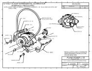
<strong>THEORY</strong> Field-drive The <strong>R1224</strong> is a totally solid state device using a Field-<br />
Effect driver IC to pulse-width modulate the FIELD signal. A regulator control IC<br />
is employed to sense voltage on the SENSE terminal and provide the pulse-width<br />
modulated signal.<br />
<strong>THEORY</strong> Overvoltage Protection The <strong>R1224</strong> has two independent overvoltage<br />
circuits. The first turns on the LAMP and reduces the pulse-width modulated<br />
signal to the FIELD (alternator rotor) to minimum width. If the voltage continues<br />
to rise, a Silicon Controlled Rectifier (SCR) “Crowbar” circuit shorts the ENABLE<br />
connection to ground, limiting the rise of the voltage while tripping the series<br />
circuit breaker.<br />
<strong>THEORY</strong> Lamp Circuit This “open collector” transistor driver can sink up to<br />
100mA safely. It draws current between the LAMP terminal and ground when:<br />
• There is no voltage on the ENABLE terminal. This may indicate that the<br />
series breaker is tripped.<br />
• There is no voltage on the AUX terminal. This may indicate that the<br />
alternator is not turning (engine stopped or belt broken).<br />
• Overvoltage has been detected.<br />
Theory Master-Slave Operation In a dual-alternator, load-balancing<br />
installation, one alternator/regulator combination is designated as “Master” and<br />
the other alternator/regulator combination is designated as “Slave”. Wiring is<br />
normal except that the OUT connection of the “Master” <strong>R1224</strong> is connected to<br />
the IN terminal of the “Slave” <strong>R1224</strong>. The voltage control circuit of the “Master”<br />
<strong>R1224</strong> controls the output of both. If the “Master” <strong>R1224</strong> fails, the “Slave”<br />
alternator/regulator combination will operate independently.