SG Body Reflector Muting.pdf - Datasensor
SG Body Reflector Muting.pdf - Datasensor
SG Body Reflector Muting.pdf - Datasensor

Create successful ePaper yourself
Turn your PDF publications into a flip-book with our unique Google optimized e-Paper software.
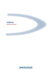
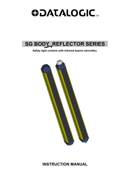
<strong>SG</strong> BODY REFLECTOR SERIES .<br />
Safety light curtains with infrared beams retroreflex<br />
INSTRUCTION MANUAL
ORIGINAL INSTRUCTIONS (ref. 2006/42/EC)<br />
This product is covered by one or more of the following patents.<br />
Italian Patent IT 1,363,719<br />
Additional patents pending<br />
DATALOGIC AUTOMATION<br />
Via Lavino 265 - 40050 Monte S.Pietro - Bologna – Italy<br />
Tel: +39 051 6765611- Fax: +39 051 6759324<br />
www.automation.datalogic.com e-mail: info.automation.it@datalogic.com<br />
DATALOGIC AUTOMATION reserves the right to make modifications and improvements without prior notification.<br />
Datalogic and the Datalogic logo are registered trademarks of Datalogic S.p.A. in many countries, including the U.S.A. and the E.U.<br />
826006001 rev.A © Copyright Datalogic 2010
<strong>SG</strong>-BODY REFLECTOR <strong>Muting</strong><br />
Instruction manual<br />
INDEX<br />
1. GENERAL INFORMATIONS ABOUT THIS DOCUMENT ................................................................................................................ 1<br />
1.1. Purpose of this document...................................................................................................................................................... 1<br />
1.2. Intended readers ................................................................................................................................................................... 1<br />
1.3. Informations for the use......................................................................................................................................................... 1<br />
2. GENERAL INFORMATIONS ABOUT THE PRODUCT .................................................................................................................... 1<br />
2.1. General description of the safety light curtains...................................................................................................................... 1<br />
2.2. Appearance and interface ..................................................................................................................................................... 2<br />
2.2.1. Package contents ........................................................................................................................................................ 2<br />
2.3. Main functions and new features........................................................................................................................................... 2<br />
2.4. How to choose the device ..................................................................................................................................................... 3<br />
2.4.1. Resolution .................................................................................................................................................................... 4<br />
2.4.2. Controlled height.......................................................................................................................................................... 5<br />
2.4.3. Minimum installation distance...................................................................................................................................... 7<br />
2.5. Typical applications ............................................................................................................................................................. 10<br />
2.6. Safety information................................................................................................................................................................ 10<br />
3. INSTALLATION MODE ................................................................................................................................................................... 11<br />
3.1. Precautions to be observed for the choice and installation of the device............................................................................ 11<br />
3.2. General information on device positioning .......................................................................................................................... 12<br />
3.2.1. Minimum installation distance.................................................................................................................................... 13<br />
3.2.2. Minimum distance from reflecting surfaces................................................................................................................ 13<br />
3.2.3. Distance between homologous devices..................................................................................................................... 15<br />
3.2.4. Active and passive orientation ................................................................................................................................... 17<br />
3.2.5. Precautions to respect during the use of deviating mirrors........................................................................................ 17<br />
3.2.6. Controls after first installation..................................................................................................................................... 18<br />
4. MECHANICAL MOUNTING............................................................................................................................................................. 18<br />
4.1. Side fixing brackets ............................................................................................................................................................. 18<br />
4.2. Rotating brackets................................................................................................................................................................. 19<br />
4.3. Bottom fixing brackets ......................................................................................................................................................... 19<br />
4.4. Vibration dampers ............................................................................................................................................................... 20<br />
4.5. Mechanical muting arms mounting...................................................................................................................................... 20<br />
4.5.1. Mechanical arm mounting (retro-reflex)..................................................................................................................... 22<br />
5. ELECTRICAL CONNECTIONS AND CONFIGURATION............................................................................................................... 22<br />
5.1. Important notes for installation ............................................................................................................................................ 23<br />
5.2. Minimal connection.............................................................................................................................................................. 23<br />
5.3. Complete connection list ..................................................................................................................................................... 24<br />
5.4. Complete dip-switches configuration................................................................................................................................... 24<br />
5.5. Restart mode and Reset/Restart button connection............................................................................................................ 25<br />
5.6. External relays connection .................................................................................................................................................. 25<br />
5.7. EDM control connection ...................................................................................................................................................... 26<br />
5.8. MUTING ENABLE input connection.................................................................................................................................... 26<br />
5.9. <strong>Muting</strong> arms or <strong>Muting</strong> function inputs connection .............................................................................................................. 26<br />
5.10. Override connection ............................................................................................................................................................ 27<br />
5.11. Earth connection.................................................................................................................................................................. 27<br />
6. FUNCTIONING MODE..................................................................................................................................................................... 28<br />
6.1. Standard configuration ........................................................................................................................................................ 28<br />
6.2. Reset function...................................................................................................................................................................... 29<br />
6.3. EDM function ....................................................................................................................................................................... 30<br />
6.4. <strong>Muting</strong> function .................................................................................................................................................................... 32<br />
6.4.1. <strong>Muting</strong> T/L selection function ..................................................................................................................................... 33<br />
6.4.2. <strong>Muting</strong> timeout selection function............................................................................................................................... 34<br />
6.4.3. <strong>Muting</strong> low-pass filter function.................................................................................................................................... 34<br />
6.4.4. Installation mode of <strong>Muting</strong> sensors .......................................................................................................................... 34<br />
6.5. Override function ................................................................................................................................................................. 38<br />
6.5.1. Activation of the Override function............................................................................................................................. 38<br />
6.5.2. Override input mode function..................................................................................................................................... 39<br />
6.5.3. Override restart mode function .................................................................................................................................. 41<br />
6.5.4. Override status........................................................................................................................................................... 41<br />
6.6. Alignment function ............................................................................................................................................................... 42<br />
7. ALIGNMENT PROCEDURE............................................................................................................................................................ 42<br />
7.1. Light curtain alignment procedure ....................................................................................................................................... 43<br />
7.2. Correct muting arm alignment procedure............................................................................................................................ 45<br />
I
Instruction manual<br />
<strong>SG</strong>-BODY REFLECTOR <strong>Muting</strong><br />
8. DIAGNOSTICS ................................................................................................................................................................................ 45<br />
8.1. User interface ...................................................................................................................................................................... 45<br />
8.2. Diagnostic messages .......................................................................................................................................................... 46<br />
8.2.1. Active unit side........................................................................................................................................................... 46<br />
9. PERIODICAL MAINTENANCE AND WARRANTY......................................................................................................................... 48<br />
9.1. General information and useful data ................................................................................................................................... 48<br />
9.2. Warranty .............................................................................................................................................................................. 48<br />
10. DEVICE MAINTENANCE ................................................................................................................................................................ 49<br />
10.1. Product disposal .................................................................................................................................................................. 49<br />
11. TECHNICAL DATA.......................................................................................................................................................................... 50<br />
12. DIMENSIONS................................................................................................................................................................................... 51<br />
13. ORDER DATA ................................................................................................................................................................................. 52<br />
14. ACCESSORIES ............................................................................................................................................................................... 53<br />
14.1. Side fixing bracket ............................................................................................................................................................... 53<br />
14.1.1. Side fixing bracket mounting...................................................................................................................................... 54<br />
14.2. Rotative fixing bracket ......................................................................................................................................................... 56<br />
14.2.1. Rotative fixing bracket mounting................................................................................................................................ 56<br />
14.3. Bottom fixing bracket ........................................................................................................................................................... 57<br />
14.3.1. Bottom fixing bracket mounting.................................................................................................................................. 57<br />
14.4. Column and floor stands...................................................................................................................................................... 58<br />
14.5. Protective stands ................................................................................................................................................................. 59<br />
14.6. Test Piece............................................................................................................................................................................ 59<br />
14.7. Laser pointer........................................................................................................................................................................ 60<br />
14.8. Connection cables ............................................................................................................................................................... 60<br />
14.9. Safety relay SE-SR2............................................................................................................................................................ 61<br />
14.10. <strong>Muting</strong> Arms ........................................................................................................................................................................ 62<br />
15. GLOSSARY ..................................................................................................................................................................................... 63<br />
II
<strong>SG</strong>-BODY REFLECTOR <strong>Muting</strong><br />
Instruction manual<br />
1. GENERAL INFORMATIONS ABOUT THIS DOCUMENT<br />
Read this section carefully before implementing the instructions given in this manual and starting up the<br />
<strong>SG</strong> BODY safety system.<br />
1.1. Purpose of this document<br />
These instructions for use are addressed to the manufacturer technicians or staff operating the<br />
machine and give all necessary instructions for correct and safe assembly, setup, electric connection<br />
and commissioning of the <strong>SG</strong> BODY series light curtains.<br />
Scope of this document excludes information about use of the machine the safety system is installed<br />
to.<br />
1.2. Intended readers<br />
The instructions for use given herein are addressed to designers, manufacturers and persons in<br />
charge of the safety of systems to be equipped with the <strong>SG</strong> BODY series light curtains. They are also<br />
addressed to the staff in charge of installing the <strong>SG</strong> BODY light curtain to a machine, commissioning it<br />
or servicing it.<br />
1.3. Informations for the use<br />
These instructions for use contain the following details about the <strong>SG</strong> BODY series light curtains:<br />
- installation - diagnostics and troubleshooting<br />
- electrical connection - user interface warnings<br />
- commissioning and setup - conformity and type approval<br />
- application - care and maintenance<br />
Designing and using safety devices to integrate to the <strong>SG</strong> BODY safety system requires specific<br />
know-how which is not included in this document. In particular, the applicable industry standards shall<br />
be met.<br />
General information about accident-prevention protection by means of optoelectronic safety devices<br />
can be found in the “Safety guide” available on the product CD-Rom provided with the product.<br />
For all the acronyms used in this document please refer to section 14.10.<br />
2. GENERAL INFORMATIONS ABOUT THE PRODUCT<br />
2.1. General description of the safety light curtains<br />
The safety light curtains of the <strong>SG</strong> BODY series are optoelectronic multibeam devices that are used to<br />
protect working areas that, in presence of machines, robots, and automatic systems in general, can<br />
become dangerous for operators that can get in touch, even accidentally, with moving parts.<br />
The light curtains of the <strong>SG</strong> BODY series are safety systems used as accident-prevention protection<br />
devices and are manufactured in accordance with the international Standards in force for safety, in<br />
particular:<br />
CEI IEC 61496-1: 2004 Safety of machinery: electro-sensitive protective equipment.<br />
Part 1: General prescriptions and tests.<br />
CEI IEC 61496-2: 2006 Safety of machinery: electro-sensitive protective equipment.<br />
Particular requirements for equipment using active optoelectronic protective<br />
devices.<br />
The device, consisting in one active unit inside a sturdy aluminium profile and a passive unit<br />
composed of two or more deviating mirrors, generates couples of infrared beams able to detect an<br />
opaque object positioned within the light curtain detection field.<br />
The active unit is composed of two types of optic groups: emitting and receiving units. The infrared<br />
beam, generated by an emitting optic group, is reflected by the deviating mirrors and thus re-guided<br />
towards the corresponding receiving optic group of the active unit.<br />
The passive unit is composed of a sturdy aluminium profile containing pre-assembled and pre-aligned<br />
mirrors.<br />
The solution with integrated <strong>Muting</strong> arms can be implemented both in a ‘T’ or ‘L’ configuration.<br />
1
Instruction manual<br />
<strong>SG</strong>-BODY REFLECTOR <strong>Muting</strong><br />
The active unit is equipped with the command and control functions. The connections are made<br />
through a M12 connector located in the lower side of the profile of the active unit.<br />
The microprocessor guarantees the check and the management of the beams that are sent and<br />
received through the units: The microprocessor LEDs and display inform the operator about the<br />
general conditions of the safety light curtain (see section Errore. L'origine riferimento non è stata<br />
trovata. - ”Errore. L'origine riferimento non è stata trovata.”).<br />
The device consists in 2 units: the active unit and the passive unit. The active unit, according to the<br />
model, is composed by one or several emitting and receiving modules and checks the control<br />
operations and safety actions.<br />
During installation, an user interface facilitates the alignment of both units (see section 7 –<br />
“ALIGNMENT PROCEDURE”).<br />
As soon as an object or the operator’s body accidentally interrupts one or some of the infrared beams<br />
sent by the emitter, the receiver immediately opens the OSSD outputs and blocks the MPCE machine<br />
(if correctly connected to the OSSD).<br />
Some parts or sections of this manual containing important information for the user or installing<br />
operator are preceded by a note:<br />
Notes and detailed descriptions about particular characteristics of the safety devices in order to better<br />
explain their functioning.<br />
Special instructions regarding the installation process.<br />
The information provided in the paragraphs following this symbol is very important for safety<br />
and may prevent accidents.<br />
Always read this information accurately and carefully follow the advice to the letter.<br />
This manual contains all the information necessary for the selection and operation of the safety<br />
devices.<br />
However, specialised knowledge not included in this technical description is required for the planning<br />
and implementation of a safety light curtain on a power-driven machine. As the required knowledge<br />
may not be completely included in this manual, we suggest the customer to contact DATALOGIC<br />
AUTOMATION Technical Service for any necessary information relative to the functioning of the <strong>SG</strong><br />
BODY light curtains and the safety rules that regulate the correct installation (see section 9 – “<br />
PERIODICAL MAINTENANCE AND WARRANTY”).<br />
2.2. Appearance and interface<br />
2.2.1. Package contents<br />
Package contains the following objects:<br />
Active unit<br />
<strong>SG</strong> BODY quick installation guide<br />
<strong>SG</strong> BODY CD containing instruction manual and other documents<br />
Checklist and periodical maintenance schedule<br />
2.3. Main functions and new features<br />
With respect to SE4-R series, the <strong>SG</strong> BODY safety light curtain series present new important features:<br />
No dead zone<br />
New engineering of passive unit<br />
Shorter response time (see section 11 – “TECHNICAL DATA”)<br />
<strong>Muting</strong> function customization<br />
Override function customization<br />
2
<strong>SG</strong>-BODY REFLECTOR <strong>Muting</strong><br />
Instruction manual<br />
2.4. How to choose the device<br />
The <strong>SG</strong> BODY series light curtains efficiently satisfy all applications that require the <strong>Muting</strong> function<br />
thanks to pre-assembled, pre-cabled and pre-aligned <strong>Muting</strong> sensors.<br />
T-shaped models are available with integrated <strong>Muting</strong> sensors for bidirectional <strong>Muting</strong>, L-shaped<br />
models for unidirectional <strong>Muting</strong> and linear models without integrated <strong>Muting</strong> sensors are available.<br />
By means of <strong>Muting</strong> arms accessories, linear models can be converted into T-shaped models and L-<br />
shaped models.<br />
The muting arms, available in “T” and “L” versions, take advantage of retroretroreflex sensors<br />
technology. This version covers a maximum operating distance of light curtain of 3 m.<br />
The integrated <strong>Muting</strong> solution with “L” configuration facilitates sensor installation and suits<br />
applications requiring one-way object passage direction.<br />
The integrated <strong>Muting</strong> solution with “T” configuration facilitates sensor installation and is ideal for<br />
applications requiring a bidirectional object passage movement.<br />
The linear models, presenting a specific connector allowing easy connection of the <strong>Muting</strong> sensors, is<br />
recommended for difficult or particular applications.<br />
Sensor positioning has to be carried out by the operator, respecting the precautions listed in the<br />
following chapters.<br />
There are at least three different main characteristics that should be considered when choosing a<br />
safety light curtain, after having evaluated the risk assessment:<br />
3
Instruction manual<br />
<strong>SG</strong>-BODY REFLECTOR <strong>Muting</strong><br />
2.4.1. Resolution<br />
The resolution of the device is the minimum dimension that an opaque object must have in order to<br />
obscure at least one of the beams that constitute the sensitive area.<br />
The resolution strictly depends on the part of the body to be protected.<br />
The following table shows the values of the optic interaxis (I), the resolution (R) and the optic diameter<br />
(d), of the safety light curtains.<br />
Model<br />
<strong>SG</strong>4-RB2-050-OO-W<br />
<strong>SG</strong>4-RB2L-050-OO-W<br />
<strong>SG</strong>4-RB2T-050-OO-W<br />
<strong>SG</strong>4-RB3-080-OO-W<br />
<strong>SG</strong>4-RB3L-080-OO-W<br />
<strong>SG</strong>4-RB3T-080-OO-W<br />
Optic<br />
interaxis<br />
(I) [mm]<br />
N.<br />
optics<br />
Resolution<br />
(R) [mm]<br />
Lens diameter<br />
(d) [mm]<br />
500 2 519,75 19,75<br />
380 3 399,75 19,75<br />
ESPE Type<br />
<strong>Body</strong> protection<br />
Type 4<br />
<strong>Body</strong> protection<br />
Type 4<br />
<strong>Body</strong> protection<br />
<strong>SG</strong>4-RB4-090-OO-W 300 4 319,75 19,75<br />
Type 4<br />
<strong>Body</strong> protection<br />
<strong>SG</strong>4-RB4-120-OO-W 400 4 419,75 19,75<br />
Type 4<br />
4
<strong>SG</strong>-BODY REFLECTOR <strong>Muting</strong><br />
Instruction manual<br />
As shown in Figure 1, the resolution depends only on the geometrical characteristics of the lenses,<br />
diameter and distance between centres, and is independent from any environmental and operating<br />
conditions of the safety light curtain.<br />
Figure 1<br />
The resolution value is obtained applying the following formula: R = I + d<br />
where:<br />
I =<br />
d =<br />
Distance between two adjacent optics<br />
Lens diameter<br />
Note: Safety light curtains for body protection with sensitive area heights and optic interaxis<br />
different from the standard versions can be manufactured upon specific request.<br />
2.4.2. Controlled height<br />
The controlled height is the height protected by the safety light curtain (Hp). <strong>SG</strong> BODY models have<br />
no dead zone inside the protected area.<br />
In Figure 2, Figure 3 and Figure 4 <strong>SG</strong> BODY <strong>Reflector</strong> schemes respectively for 2 beams, 3 beams<br />
and 4 beams models are shown.<br />
5
Instruction manual<br />
<strong>SG</strong>-BODY REFLECTOR <strong>Muting</strong><br />
Figure 2<br />
Figure 3<br />
6
<strong>SG</strong>-BODY REFLECTOR <strong>Muting</strong><br />
Instruction manual<br />
Figure 4<br />
Model Hp [mm] ESPE Type<br />
<strong>Body</strong> protection<br />
<strong>SG</strong>4-RB2-050-OO-W<br />
<strong>SG</strong>4-RB2L-050-OO-W<br />
<strong>SG</strong>4-RB2T-050-OO-W<br />
500<br />
<strong>SG</strong>4-RB3-080-OO-W<br />
<strong>SG</strong>4-RB3L-080-OO-W<br />
<strong>SG</strong>4-RB3T-080-OO-W<br />
800<br />
<strong>SG</strong>4-RB4-090-OO-W 900<br />
Type 4<br />
<strong>Body</strong> protection<br />
Type 4<br />
<strong>Body</strong> protection<br />
<strong>SG</strong>4-RB4-120-OO-W 1200<br />
Type 4<br />
<strong>Body</strong> protection<br />
Type 4<br />
2.4.3. Minimum installation distance<br />
As shown in Figure 5, the safety device must be positioned at a specific safety distance. This distance<br />
must ensure that the dangerous area cannot be reached before the dangerous motion of the machine<br />
has been stopped by the ESPE.<br />
7
Instruction manual<br />
<strong>SG</strong>-BODY REFLECTOR <strong>Muting</strong><br />
The safety distance depends on 4 factors, according to the EN-999 “Safety of machinery - The<br />
positioning of protective equipment in respect of approach speeds of parts of the human<br />
body” Standard:<br />
Response time of the ESPE (the time between the effective beam interruption and the<br />
opening of the OSSD contacts).<br />
Machine stopping time (the time between the effective opening of the contacts of the ESPE<br />
and the real stop of the dangerous motion of the machine).<br />
ESPE resolution.<br />
Approaching speed of the object to be detected.<br />
Figure 5<br />
The following formula is used for the calculation of the safety distance:<br />
S = K (t 1 + t 2 ) + C<br />
where:<br />
S = Minimum safety distance in mm.<br />
K = Speed of the object, limb or body approaching the dangerous area in mm/sec.<br />
t 1 = Response time of the ESPE in seconds (see section 11 – “TECHNICAL DATA”)<br />
t 2 = Machine stopping time in seconds.<br />
d = Resolution of the system.<br />
C = Additional distance based on the possibility to insert the body or one of body parts inside the<br />
dangerous area before the protective device trips.<br />
C = 8 (d -14) for devices with resolution ≤ 40mm<br />
C = 850 mm for devices with resolution > 40mm<br />
8
<strong>SG</strong>-BODY REFLECTOR <strong>Muting</strong><br />
Instruction manual<br />
NOTE: K value is:<br />
2000 mm/s if the calculated value of S is ≤ 500 mm<br />
1600 mm/s if the calculated value of S is > 500 mm<br />
When devices with > 40 mm resolution are used, the height of the top beam has to be ≥ 900 mm (H2)<br />
from machine supporting base while the height of the bottom beam has to be ≤ 300 mm (H1).<br />
If the safety light curtain must be mounted in a horizontal position (Figure 6), the distance between the<br />
dangerous area and the most distant optical beam must be equal to the value calculated using the<br />
following formula:<br />
S = 1600 mm/s (t 1 + t 2 ) + 1200 – 0.4 H<br />
where:<br />
S = Minimum safety distance in mm.<br />
t 1 = Response time of the ESPE in seconds (see section 11 – “TECHNICAL DATA”)<br />
t 2 = Machine stopping time in seconds.<br />
H = Beam height from ground. This height must always be less than 1000 mm.<br />
Figure 6<br />
Practical examples<br />
Let's suppose to have a light curtain with height = 500 mm<br />
To calculate the distance of the device from the ESPE, in a vertical position, the following formula is<br />
used:<br />
S = K*T + C<br />
where:<br />
T = t 1 + t 2<br />
t 1 = ESPE response time + SE-SR2 relay release time (max 80 ms)<br />
t 2 = Machine total stopping time (e.g. 300 ms).<br />
C = 8 (d -14) for devices with resolution ≤ 40mm<br />
C = 850 mm for devices with resolution > 40mm<br />
d = resolution<br />
In all cases, if K = 2000mm/sec then S > 500 mm. Distance will have then to be recalculated using K<br />
= 1600 mm/sec.<br />
<strong>SG</strong>x-RB2<br />
<strong>SG</strong>x-RB4<br />
T [sec] 0.391 0.392<br />
C [mm] 850 850<br />
S [mm] 1475.6 1477.2<br />
x = ESPE Type: 2,4<br />
9
Instruction manual<br />
<strong>SG</strong>-BODY REFLECTOR <strong>Muting</strong><br />
WARNING: The reference standard is EN 999 “Machine safety - the positioning of the protective<br />
device based on the approaching speed of the human body”. The following information is to be<br />
considered as indicative and concise. For correct safety distance please refer to complete standard<br />
EN-999.<br />
2.5. Typical applications<br />
The SAFEasy TM safety light curtains of the <strong>SG</strong> BODY Series are used in all automation fields where<br />
control and protection of the access to dangerous zones is necessary, as well as allowing, by means<br />
of the <strong>Muting</strong> function, material passage inside a dangerous zone during working.<br />
In particular they are used to stop the moving mechanical parts in:<br />
- Access control<br />
- Working areas<br />
- Packaging machines, handling machines, storing machines;<br />
- Automatic and semi–automatic assembly lines;<br />
- Automatic warehouses;<br />
- Robotics.<br />
In food industry applications, Datalogic Automation Technical Service has to verify the compatibility of<br />
the material of the safety light curtain housing with any chemical agents used in the production<br />
process.<br />
The following pictures show some main applications.<br />
Figure 7 - Robotised assembly lines<br />
2.6. Safety information<br />
Figure 8 - Transfer areas<br />
For a correct and safe use of the safety light curtains of the <strong>SG</strong> BODY series, the following points<br />
must be observed:<br />
<br />
The stopping system of the machine must be electrically controlled.<br />
<br />
This control system must be able to stop the dangerous movement of the machine within the total<br />
machine stopping time T as per paragraph 2.4.3, and during all working cycle phases.<br />
<br />
Mounting and connection of the safety light curtain must be carried out by qualified personnel only,<br />
according to the indications included in the special sections (refer to sections 3, 4, 5, 7) and to the<br />
applicable standards.<br />
<br />
The safety light curtain must be securely placed in a particular position so that access to the<br />
dangerous zone is not possible without the interruption of the beams (refer section 3 –<br />
“INSTALLATION MODE”).<br />
10
<strong>SG</strong>-BODY REFLECTOR <strong>Muting</strong><br />
Instruction manual<br />
<br />
The personnel operating in the dangerous area must be well trained and must have adequate<br />
knowledge of all the operating procedures of the safety light curtain.<br />
<br />
The TEST button must be located outside the protected area because the operator must check the<br />
protected area during all the Test operation.<br />
<br />
The RESET/RESTART button must be located outside the protected area because the operator must<br />
check the protected area during all the Reset/Restart operations.<br />
<br />
The OVERRIDE buttons must be located outside the protected area because the operator must check<br />
the protected area during all the Override operations.<br />
<br />
The external signalling lamp of the active <strong>Muting</strong>/Override must be visible from all operating sides.<br />
<br />
Please carefully respect the mounting instructions for the correct functioning of the <strong>Muting</strong> devices.<br />
<br />
The function of the external device monitoring (EDM) is active only if the specific wire is correctly<br />
connected to the device. Please carefully read the instructions for the correct functioning before<br />
powering the light curtain.<br />
<br />
Please carefully read the instructions for the correct functioning before powering the light curtain.<br />
3. INSTALLATION MODE<br />
3.1. Precautions to be observed for the choice and installation of the device<br />
Make sure that the protection level assured by the <strong>SG</strong> BODY series device (Type 2 or Type 4<br />
respectively) is compatible with the real danger level of the machine to be controlled, according to EN<br />
954-1 and EN13849-1.<br />
The outputs (OSSD) of the ESPE must be used as machine stopping devices and not as command<br />
devices (the machine must have its own START command).<br />
The dimension of the smallest object to be detected must be larger than the resolution level of the<br />
device.<br />
The ESPE must be installed in a room complying with the technical characteristics indicated in section<br />
11 - TECHNICAL DATA. Datalogic Automation does not recommend the use of the product in<br />
ambients where direct or indirect exposure to solar light is present.<br />
Do not install device near strong and/or flashing light sources or close to similar devices.<br />
Strong electromagnetic disturbance might negatively affect device operation. Should this be the case<br />
contact DATALOGIC Technical Service.<br />
The operating distance of the device can be reduced in presence of smog, fog or airborne dust.<br />
A sudden change in environment temperature, with very low minimum peaks, can generate a small<br />
condensation layer on the lenses and so jeopardise functioning.<br />
The <strong>Muting</strong>/Override function is signalled by a specific <strong>Muting</strong>/Override signalling lamp. Ensure that<br />
the signalling device has sufficient lighting and visibly positioned near the dangerous zone.<br />
Ensure to correctly use <strong>Muting</strong> sensors as described in the instructions supplied hereinafter. Avoid<br />
incongruent connections that cannot be controlled and thus excluding undesired potentially dangerous<br />
activations.<br />
11
Instruction manual<br />
<strong>SG</strong>-BODY REFLECTOR <strong>Muting</strong><br />
3.2. General information on device positioning<br />
Pay special care when positioning the safety light curtain so to offer effective protection. The device<br />
should be installed in such a way that the dangerous area can only be entered after detecting the<br />
sensitive area.<br />
Figure 9 shows some examples of possible access to the machine from the top and the bottom sides.<br />
These situations may be very dangerous and so the installation of the safety light curtain at sufficient<br />
height in order to completely cover the access to the dangerous area becomes necessary (see Figure<br />
10).<br />
NO<br />
Figure 9<br />
YES<br />
Figure 10<br />
Under standard operating conditions, machine starting must not be possible while operators are inside<br />
the dangerous area.<br />
When the installation of the safety light curtain very near to the dangerous area is not possible, a<br />
second light curtain must be mounted in a horizontal position in order to prevent any lateral access, as<br />
shown in Errore. L'origine riferimento non è stata trovata..<br />
If the operator is able to enter the dangerous area, an additional mechanical protection must be<br />
mounted to prevent the access.<br />
12
<strong>SG</strong>-BODY REFLECTOR <strong>Muting</strong><br />
Instruction manual<br />
NO<br />
YES<br />
Figure 11 Figure 12<br />
3.2.1. Minimum installation distance<br />
Refer to paragraph 2.4.3 - Minimum installation distance.<br />
3.2.2. Minimum distance from reflecting surfaces<br />
Reflecting surfaces placed near the light beams of the safety device (over, under or laterally) can<br />
cause passive reflections. These reflections can affect the recognition of an object inside the<br />
controlled area.<br />
However, if the RX receiver detects a secondary beam (reflected by the side-reflecting surface) the<br />
object might not be detected, even if the object interrupts the main beam.<br />
ACTIVE<br />
UNIT<br />
PASSIVE<br />
UNIT<br />
ACTIVE<br />
UNIT<br />
PASSIVE<br />
UNIT<br />
Figure 13<br />
13
Instruction manual<br />
<strong>SG</strong>-BODY REFLECTOR <strong>Muting</strong><br />
It is thus important to position the safety light curtain according to the minimum distance from reflecting<br />
surfaces.<br />
The minimum distance depends on:<br />
operating distance between active and passive units.<br />
real aperture angle of ESPE (EAA); especially:<br />
for ESPE type 4 EAA MAX = 5° (α = ± 2.5°)<br />
Diagram of Figure 14 shows the minimum distance from the reflecting surface (D sr ), based on the<br />
operating distance for a Type 4 ESPE:<br />
Minimum distance from reflecting surfaces (DSR)<br />
Figure 14<br />
The formula to get D sr for a Type 4 ESPE is the following:<br />
D sr (m) = 0.15<br />
D sr (m) = 0.5 x operating distance (m) x tg 2<br />
for operating distance < 3 m<br />
for operating distance 3 m<br />
Even in presence of beam interruption due to reflecting objects, the correct device functioning is<br />
guaranteed and certified up to a maximum operating distance of 6.5m for <strong>SG</strong>4-RB4-090 model, or 8 m<br />
for <strong>SG</strong>4-RB2-050, <strong>SG</strong>4-RB3-080, <strong>SG</strong>4-RB4-120 models. The use of the device at higher distances,<br />
when possible, is however not recommended. If used, the user must check the correct functioning<br />
verifying that no dangerous reflections towards the receiving optics are generated by shiny objects<br />
(Figure 15).<br />
14
<strong>SG</strong>-BODY REFLECTOR <strong>Muting</strong><br />
Instruction manual<br />
Figure 15<br />
3.2.3. Distance between homologous devices<br />
If different safety devices have to be installed in adjacent areas, the emitter of one device must not<br />
interfere dangerously with the receiver of the other device.<br />
Passive B interfering device must be positioned outside a minimum D do distance from the active –<br />
passive axis of the device A.<br />
Figure 16<br />
This minimum D do distance depends on:<br />
the operating distance between Passive A and Active A;<br />
the effective aperture angle of the ESPE (EAA); especially:<br />
for ESPE type 4 EAA MAX = 5° (α = ± 2.5°)<br />
WARNING: the interfering device Passive B must be positioned at the same D do distance, calculated<br />
as shown above, even if closer to Passive A respect to Active A.<br />
The following graphic shows the distance from the interfering devices (D do ) according to the operating<br />
distance (D op ) of the couple Passive A – Active A for a Type 4 ESPE.<br />
15
Instruction manual<br />
<strong>SG</strong>-BODY REFLECTOR <strong>Muting</strong><br />
Homolugous devices distance (Ddo)<br />
Figure 17<br />
The formula to get D op for a Type 4 ESPE is the following:<br />
D op (m) = 0.3<br />
D op (m) = operating distance (m) x tg 2<br />
for operating distance < 3 m<br />
for operating distance 3 m<br />
Installation precautions have to be taken to avoid interference between homologous devices. A typical<br />
situation is represented by the installation areas of several adjacent safety devices aligned one next to<br />
the other, for example in plants with different machines.<br />
Figure 18 provides some examples for a 4 beam device; obviously a contemporary activation of more<br />
emitters is not possible and the emitter/receiver couples are activated sequentially.<br />
16
<strong>SG</strong>-BODY REFLECTOR <strong>Muting</strong><br />
Instruction manual<br />
Figure 18<br />
3.2.4. Active and passive orientation<br />
The two units shall be assembled parallel each other, and looking at the references on the aluminium<br />
profile.<br />
The configurations shown in Figure 19 must be avoided:<br />
NO<br />
NO<br />
Figure 19<br />
3.2.5. Precautions to respect during the use of deviating mirrors<br />
The operator must observe the following precautions when using the deviating mirrors:<br />
The alignment of the active unit can become a very critical operation when deviating mirrors are used.<br />
Even a very small angular displacement of the mirror is enough to loose alignment. The <strong>SG</strong>-LP laser<br />
pointer accessory can be used to avoid this problem.<br />
The presence of dust or dirt on the reflecting surface of the mirror causes a drastic reduction in the<br />
range.<br />
17
Instruction manual<br />
<strong>SG</strong>-BODY REFLECTOR <strong>Muting</strong><br />
3.2.6. Controls after first installation<br />
The control operations to carry-out after the first installation and before machine start-up are listed<br />
hereinafter. The controls must be carried-out by qualified personnel, either directly or under the strict<br />
supervision of the person in charge of machinery Safety.<br />
Verify that:<br />
ESPE remains in SAFE state ( ) intercepting the beams along the protected area using the<br />
specific test piece (TP-40, TP-50, TP-90), following the Figure 20 scheme.<br />
Figure 20<br />
ESPE has to be correctly aligned, press slightly on the product side in both directions the red LED<br />
must not turn on .<br />
The activation of the TEST function causes the opening of the OSSD outputs (red LED on and<br />
controlled machine stop).<br />
The response time at machine STOP, including the ESPE and machine response times, must be<br />
included in the limits defined in the calculation of the safety distance (refer to section 3 –<br />
“INSTALLATION MODE”).<br />
The safety distance between the dangerous parts and ESPE must comply with the requirements<br />
indicated in section 3 – “INSTALLATION MODE”.<br />
A person must not access or remain between ESPE and the dangerous parts of the machine.<br />
Access to the dangerous areas of the machine must not be possible from any unprotected area.<br />
ESPE must not be disturbed by external light sources, ensuring that it remains in NORMAL<br />
OPERATION condition for at least 10-15 minutes and, placing the specific test piece in the protected<br />
area, in the SAFE state for the same period.<br />
Verify the correspondence of all the accessory functions, activating them in the different operating<br />
conditions.<br />
4. MECHANICAL MOUNTING<br />
The active and passive units must be installed with the relevant sensitive surfaces facing each other<br />
and the distance must be included within the operating range of the model used (see section 13).<br />
The two units must be positioned the most aligned and parallel possible.<br />
The next step is the fine alignment, as shown in section 7 – “ALIGNMENT PROCEDURE”.<br />
<strong>SG</strong> BODY series light curtains are provided without mounting brackets. It is possible to order separately<br />
the accessory kits of brackets described in the following paragraphs depending on the fastening mode<br />
required by the particular application. Please refer to section 0 – “ACCESSORIES”.<br />
4.1. Side fixing brackets<br />
As all the Datalogic Automation <strong>SG</strong> series safety light curtains, the most common way to fix the<br />
product is by taking advantage from the two grooves along the sides of the aluminium case, the 90°<br />
bracket system is made by ST-5090 + IM-5018 and screws (see Figure 21).<br />
18
<strong>SG</strong>-BODY REFLECTOR <strong>Muting</strong><br />
Instruction manual<br />
Figure 21<br />
The ST-5090 is a 4 mm thickness sheet metal. The IM-5018 is a double nut M5 tapped obtained by<br />
machine tooling (for further details and recommended mounting positions see also paragraph 14.1).<br />
4.2. Rotating brackets<br />
The rotative fixing has been improved and revised due to the size of the caps. Is possible indeed to<br />
ensure a 360° rotation around the dedicated cylindrical surfaces designed on the caps themselves. To<br />
obtain this is necessary to use the ST-5089, 4 mm thickness sheet metal with a special, dedicated<br />
shape. The screw to fix this bracket is the same one used to fix the closing caps, with an M4 nut (see<br />
Figure 22). For further informations refer to paragraph 14.2.<br />
Figure 22<br />
4.3. Bottom fixing brackets<br />
With the <strong>SG</strong> BODY series has been implemented a new kind of bracket fixing, by using the third<br />
groove, on the bottom side of the housing, that allows to use whether the 90° bracket ST-5090 or the<br />
new ST-5093 and, in both the cases, the same IM-5018 and screws seen before.<br />
This kind of fixing is also very versatile in order to assembly the product into the new Protective Stands<br />
mechanical armor.<br />
19
Instruction manual<br />
<strong>SG</strong>-BODY REFLECTOR <strong>Muting</strong><br />
Figure 23<br />
The ST-5093 is a 4 mm thickness sheet metal as well. For further details and recommended mounting<br />
positions see also paragraph 14.2.<br />
4.4. Vibration dampers<br />
In case of applications with particularly strong vibrations, vibration dampers together with mounting<br />
brackets are recommended to reduce the impact of the vibrations (see<br />
Figure 24).<br />
Figure 24<br />
4.5. Mechanical muting arms mounting<br />
<strong>SG</strong> BODY light curtains linear models are not provided as “L” or “T” models. These models must be<br />
built from linear models applying <strong>Muting</strong> arms accessories. Single sensor and reflector arms (RRX<br />
versions) are available as accessories and must be combined with the kit of mounting brackets for <strong>SG</strong><br />
BODY light curtains. (refer to section 14 – “ACCESSORIES”).<br />
To mount the <strong>Muting</strong> arms on both the “L” and “T” version, use the fixing bracket shown in Figure 25.<br />
20
<strong>SG</strong>-BODY REFLECTOR <strong>Muting</strong><br />
Instruction manual<br />
Figure 25<br />
This accessory guarantees the perfect alignment of the arms and the perpendicularity respect to the<br />
main unit. Position the bracket on the main unit, after having mounted the arm or arms, as shown in<br />
Figure 26.<br />
Figure 26<br />
Verify the correct functioning position and block the group using the two plates and the screws and<br />
tightening them with a CH.2.5 allen key.<br />
In the “L” version mount the arms in order to intercept the object before entering in the light curtain<br />
sensitive area.<br />
The two arms have to be mounted in order to be the most parallel and aligned possible. The sensors<br />
have default alignment, but the rotation around the main arm can be further adjusted by regulating the<br />
specific fixing bracket.<br />
In critical applications due to the presence of strong vibrations, the arms have to be fixed using the<br />
specific fixing brackets<br />
<br />
Figure 27.<br />
The <strong>Muting</strong> arms can be adjusted vertically according to the application and to the connecting cable<br />
lengths (typical range is 14 cm).<br />
21
Instruction manual<br />
<strong>SG</strong>-BODY REFLECTOR <strong>Muting</strong><br />
In presence of strong vibrations fixing brackets (see paragraph 4.1) for the <strong>Muting</strong> arms mounting are<br />
compulsory (Figure 27), which are optional in normal working conditions.<br />
Figure 27<br />
4.5.1. Mechanical arm mounting (retro-reflex)<br />
The following aspects have to be considered during the mechanical arm mounting for the “L” and “T”<br />
light curtain models:<br />
Mount the arm with the active <strong>Muting</strong> sensors on the active unit and the arms with the reflectors on the<br />
passive unit.<br />
The use of retro-reflex arms for the <strong>Muting</strong> function limits the maximum operating distance to 3 meters.<br />
5. ELECTRICAL CONNECTIONS AND CONFIGURATION<br />
All electrical connections to the emitting and receiving units are made through male M12 connectors,<br />
located on the lower part of the two units.<br />
For active unit a M12 12-poles and a M12 5-poles connectors are used.<br />
A closing cap coupled with the top cap of the RX unit can be unscrewed to access dip-switches slot.<br />
By means of internal dip-switches the user can set-up some functions, as described in paragraph 5.4.<br />
Figure 28<br />
22
<strong>SG</strong>-BODY REFLECTOR <strong>Muting</strong><br />
Instruction manual<br />
5.1. Important notes for installation<br />
For the correct functioning of the <strong>SG</strong> BODY series safety light curtains, the following precautions<br />
regarding the electrical connections have to be respected:<br />
Do not place connection cables in contact with or near high-voltage cables and/or cable undergoing<br />
high current variations (e.g. motor power supplies, inverters, etc.);<br />
<br />
Do not connect in the same multi-pole cable the OSSD wires of different light curtains;<br />
The device is already equipped with internal overvoltage and overcurrent suppression devices. The<br />
use of other external components is not recommended.<br />
5.2. Minimal connection<br />
Dip switches configuration: EDM disabled<br />
1 2 3 4 5 6 7 8<br />
Dip switches n°1,2,3,4,5,7,8: ON<br />
Dip switches n°6: OFF<br />
1 2 3 4 5 6 7 8<br />
Wires configuration: automatic restart<br />
Power supply: 0V, 24V<br />
+24Vdc<br />
0V<br />
NC<br />
RESET/RESTART/RESTART MODE<br />
line<br />
OTHER lines: floating<br />
23
Instruction manual<br />
<strong>SG</strong>-BODY REFLECTOR <strong>Muting</strong><br />
5.3. Complete connection list<br />
RX<br />
M12 12 poles:<br />
1. 24V (brown)<br />
2. 0V (blue)<br />
3. RESET/RESTART/ RESTART MODE (white)<br />
4. OVERRIDE1 (green)<br />
5. OSSD2 (pink)<br />
6. EDM (yellow)<br />
7. MUTING ENABLE (black)<br />
8. OSSD1 (grey)<br />
9. OVERRIDE2 (red)<br />
10. LAMP INPUT (violet)<br />
11. OVERRIDE STATUS (grey-pink)<br />
12. EARTH (red-blue)<br />
M12 5 poles:<br />
1. 24V (brown)<br />
2. MUTING2 (white)<br />
3. 0V (blue)<br />
4. MUTING1 (black)<br />
5. N.C. (grey)<br />
5.4. Complete dip-switches configuration<br />
The device does not accept configuration changes during normal functioning. A change is accepted<br />
only beginning from the successive powering of the device. Particular attention has to be taken during<br />
the configuration dip-switch management and use.<br />
<strong>Muting</strong> time-out “” does not comply with the requirements of IEC 61496-1. Therefore all<br />
possible risks must be considered and related precautions undertaken before selecting the<br />
“”option.<br />
Note: For RX side the top and bottom dip-switches must be configured in the same manner.<br />
The “ON” position is the default.<br />
24
<strong>SG</strong>-BODY REFLECTOR <strong>Muting</strong><br />
Instruction manual<br />
1 2 3 4 5 6 7 8<br />
1 2 3 4 5 6 7 8<br />
Dip switches n°1: <strong>Muting</strong> timeout<br />
Dip switches n°2: <strong>Muting</strong> T/L<br />
Dip switches n°3: <strong>Muting</strong> filter<br />
Dip switches n°4: Override restart<br />
Dip switches n°5: Override mode<br />
Dip switches n°6: EDM enable<br />
Dip switches n°7: not used<br />
Dip switches n°8: not used<br />
ON<br />
10 min<br />
T<br />
Disabled<br />
Manual<br />
Maintained<br />
EDM on<br />
-<br />
-<br />
OFF<br />
<br />
L<br />
Enabled<br />
Automatic<br />
Impulsive<br />
EDM off<br />
-<br />
-<br />
5.5. Restart mode and Reset/Restart button connection<br />
The Restart mode and Reset/Restart wire must be connected through a N.C. button to the 0V or 24V<br />
from the power supply of the ESPE to select, respectively, manual restart or automatic restart.<br />
The Reset/Restart wire can be used to enter alignment function, when N.C. button is pressed at startup.<br />
The RESET/RESTART button must be located in such a way that the operator can check the<br />
protected area during any reset operation (see section ).<br />
5.6. External relays connection<br />
Example: connection to the safety relay.<br />
Figure 29<br />
The previous figure shows the connection between the safety light curtains and the safety relay of the<br />
SE-SR2 series functioning in the Automatic Restart mode (left side) and Manual Restart with<br />
monitoring (right side).<br />
Do not use varistors, RC circuits or LEDs in parallel at relay inputs or in series at OSSD outputs.<br />
The OSSD1 and OSSD2 safety contacts cannot be connected in series or in parallel, but must be<br />
used separately (Figure 30), conforming to the plant’s safety requirements.<br />
If one of these configurations is erroneously used, the device enters into the output failure condition<br />
(see section Errore. L'origine riferimento non è stata trovata. – “Errore. L'origine riferimento non<br />
è stata trovata.”).<br />
25
Instruction manual<br />
<strong>SG</strong>-BODY REFLECTOR <strong>Muting</strong><br />
Connect both OSSDs to the activating device. Failure to connect an OSSD to the activating device<br />
jeopardises the system safety degree that the light curtain has to control.<br />
YES<br />
Figure 30<br />
NO<br />
Figure 31<br />
24Vdc<br />
OSSD1<br />
GND<br />
24Vdc<br />
GND<br />
OSSD2<br />
115 usec<br />
500 msec<br />
1000 msec<br />
OSSD test behaviour in<br />
NORMAL OPERATION state<br />
Figure 32<br />
5.7. EDM control connection<br />
The EDM wire has to be connected to a 24 Vdc normally closed contact, before powering. The<br />
monitoring function, if selected, is not activated if at powering the wire is not correctly connected; in<br />
this case the light curtain enters in a failure condition.<br />
5.8. MUTING ENABLE input connection<br />
The MUTING ENABLE wire must be connected to 0V or 24V from the power supply of the ESPE,<br />
respectively, to enable or to disable <strong>Muting</strong> function. Floating line level is the same as 0V.<br />
5.9. <strong>Muting</strong> arms or <strong>Muting</strong> function inputs connection<br />
<strong>Muting</strong> arms or external <strong>Muting</strong> sensors can be connected to ESPE by mean of the committed M12<br />
connector. Read see par. 6.4 – “<strong>Muting</strong> function” for the use and the positioning of the activating<br />
sensors.<br />
26
<strong>SG</strong>-BODY REFLECTOR <strong>Muting</strong><br />
Instruction manual<br />
5.10. Override connection<br />
The Override1 wire must be connected through a N.O. button to the 24 Vdc from the power supply of<br />
the ESPE; Override 2 wire must be connected through a N.O. button to the 0V from the power supply<br />
of the ESPE. If the wires are not correctly connected, the light curtain enters in a failure condition.<br />
The OVERRIDE button/key must be located in such a way that the operator can check the protected<br />
area during any test.<br />
5.11. Earth connection<br />
The <strong>SG</strong> BODY safety light curtain has to be connected as a protective class III equipment<br />
(SELV/PELV power supply), like in the table.<br />
Electrical protection layout connection note<br />
class III SELV/PELV ---<br />
A functional earth is available on a line of the M12 connector on TX and RX equipment.<br />
User can optionally connect or leave floating the functional earth in order to achieve in own<br />
application a best compliance with electromagnetic Interferences.<br />
27
Instruction manual<br />
<strong>SG</strong>-BODY REFLECTOR <strong>Muting</strong><br />
6. FUNCTIONING MODE<br />
6.1. Standard configuration<br />
Line Layout connection Behaviour<br />
RESET/RESTART/<br />
RESTART MODE<br />
+24Vdc<br />
NC<br />
IN line<br />
Automatic restart<br />
RESET/RESTART/<br />
NC<br />
0V<br />
RESTART MODE<br />
IN line<br />
Manual restart<br />
24Vdc<br />
OSSD_1<br />
nc<br />
no<br />
EDM<br />
OSSD_2<br />
(EDM ENABLE: active)<br />
nc<br />
no<br />
EDM<br />
to ESPE<br />
forced guide relais<br />
MUTING ENABLE<br />
0V or floating<br />
MUTING<br />
ENABLE <strong>Muting</strong> enabled<br />
OVERRIDE STATUS<br />
External control OVERRIDE STATUS<br />
MUTING1<br />
MUTING SENSOR/ARM OUTPUT MUTING 1<br />
MUTING2<br />
MUTING SENSOR/ARM OUTPUT MUTING 2<br />
OVERRIDE1<br />
+24Vdc<br />
NO<br />
OVERRIDE1<br />
NO<br />
OVERRIDE2 0V OVERRIDE2<br />
OSSDs<br />
OSSDs<br />
0V<br />
24V<br />
LAMP INPUT<br />
LAMP<br />
The following table shows factory default configuration for dip-switches.<br />
28
<strong>SG</strong>-BODY REFLECTOR <strong>Muting</strong><br />
Instruction manual<br />
1 2 3 4 5 6 7 8<br />
1 2 3 4 5 6 7 8<br />
Dip switches n°1: <strong>Muting</strong> timeout<br />
Dip switches n°2: <strong>Muting</strong> T/L<br />
Dip switches n°3: <strong>Muting</strong> filter<br />
Dip switches n°4: Override restart<br />
Dip switches n°5: Override mode<br />
Dip switches n°6: EDM enable<br />
Dip switches n°7: not used<br />
Dip switches n°8: not used<br />
ON<br />
10 min<br />
T<br />
Disabled<br />
Manual<br />
Maintained<br />
EDM on<br />
-<br />
-<br />
6.2. Reset function<br />
The RX light curtain has a RESET function that is activated consequently to an internal failure.<br />
The operator has to press the NC RESET button that resetting the break condition and thus the ESPE<br />
can return to a normal functioning behaviour .<br />
The button has to be kept pressed for at least 5 seconds in one of the following conditions:<br />
Output failure;<br />
Optic failure;<br />
EDM test function failure;<br />
Lamp failure;<br />
Safety light curtain STATUS<br />
Failure<br />
Normal<br />
Contact<br />
open<br />
RESET<br />
Contact<br />
close<br />
5 sec<br />
If the error is not removed, the light curtain goes in the failure configuration (for all failures) yet.<br />
Notes: the micro controller failure is a non-restorable failure. In this case is necessary a “turn OFFturn<br />
ON action” to return to a normal behavior. This is also valid for the following failures:<br />
Restart selection failure<br />
Override connection failure<br />
Override sequence failure<br />
Dip switch failure<br />
29
Instruction manual<br />
<strong>SG</strong>-BODY REFLECTOR <strong>Muting</strong><br />
Restart mode selection function<br />
The interruption of a beam due to an opaque object causes the opening of OSSD outputs and the stop<br />
of the safety light curtain, SAFE condition .<br />
ESPE standard operation can be reset to NORMAL OPERATION condition (OSSD safety contact<br />
closing condition, ) in two different ways:<br />
Automatic Restart: after activation, ESPE resets to NORMAL OPERATION condition once the object<br />
has been removed from the controlled area.<br />
Manual Restart: after activation, ESPE resets to NORMAL OPERATION condition only once the<br />
Restart function has been enabled and provided that the object has been removed from the controlled<br />
area (see Figure 33). This condition, called interlock, is signalled on the display (see paragraph 8.2 –<br />
“Diagnostic messages”).<br />
WARNING: Carefully assess risk conditions and restart modes.<br />
In applications protecting access to dangerous areas, the automatic restart mode is potentially unsafe<br />
if it allows the operator to pass completely beyond the sensitive area. In this case, the manual restart<br />
or, for example, the manual restart of the SE-SR2 relay (paragraph 5.6 – “External relays connection”)<br />
is necessary.<br />
OSSDs STATUS<br />
NORMAL<br />
OPERATION<br />
SAFE<br />
INTERLOCK STATUS<br />
ON<br />
OFF<br />
RESTART<br />
Contact<br />
open<br />
Contact<br />
close<br />
0.5 sec<br />
Figure 33 – Time chart for manual restart<br />
Select either automatic or manual restart by connecting pin of RX connector (see section 5 –<br />
“ELECTRICAL CONNECTIONS AND CONFIGURATION”).<br />
6.3. EDM function<br />
The light curtain has a function for monitoring actuation external devices (EDM). This function can be<br />
enabled or deactivated by dip-switches of RX device (see section 5 – “ELECTRICAL CONNECTIONS<br />
AND CONFIGURATION”).<br />
EDM deactivated:<br />
Disconnect or connect to 0V EDM input pin of RX connector.<br />
EDM enabled:<br />
Connect EDM input pin of RX connector (see section 5 – “ELECTRICAL CONNECTIONS AND<br />
CONFIGURATION”) to a 24 VDC normally closed contacts of the device to be monitored (see Figure<br />
34).<br />
NOTE: The decimal dot on the display shows that the function is enabled.<br />
30
<strong>SG</strong>-BODY REFLECTOR <strong>Muting</strong><br />
Instruction manual<br />
24Vdc<br />
OSSD_1<br />
nc<br />
no<br />
OSSD_2<br />
nc<br />
no<br />
EDM<br />
to ESPE<br />
forced guide relais<br />
Figure 34<br />
The function controls the NC contact switching according to the changes of the OSSD status.<br />
The timing diagram below explains the relationship between the cause (OSSDs) and the effect (EDM),<br />
with the maximum permissible delay.<br />
OSSDs STATUS<br />
NORMAL<br />
OPERATION<br />
SAFE<br />
EDM<br />
24Vdc<br />
0Vdc<br />
Tc<br />
To<br />
Figure 35<br />
Tc <br />
T0 <br />
350 msec time after the OSSD OFF-ON passage when EDM is carried-out;<br />
100 msec time after the OSSD ON-OFF passage when EDM is carried-out.<br />
(two different times for the mechanical contact driven by a spring).<br />
31
Instruction manual<br />
<strong>SG</strong>-BODY REFLECTOR <strong>Muting</strong><br />
6.4. <strong>Muting</strong> function<br />
This function can be enabled or deactivated by pin of RX connector (see section 5 – “ELECTRICAL<br />
CONNECTIONS AND CONFIGURATION”).<br />
The <strong>Muting</strong> sensors must be able to recognise the passing material (pallets, vehicles, …) according to<br />
the material’s length and speed. In case of different transport speeds in the <strong>Muting</strong> area, it is<br />
necessary to consider their effect on the total <strong>Muting</strong> duration.<br />
The <strong>Muting</strong> function, excludes the light curtain during functioning, maintaining active the OSSD<br />
outputs, according to particular operating requirements (Figure 36).<br />
L-shaped version with integrated <strong>Muting</strong><br />
sensors for unidirectional <strong>Muting</strong><br />
T-shaped version with integrated <strong>Muting</strong><br />
sensors for bidirectional <strong>Muting</strong><br />
Linear version with external <strong>Muting</strong> sensors<br />
Figure 36<br />
<br />
The safety light curtain is equipped with two inputs (<strong>Muting</strong>1 and <strong>Muting</strong>2) for the activation of this<br />
function, according to the Standards in force.<br />
This function is particularly suitable when an object, but not a person, has to pass through the<br />
dangerous area, under certain conditions.<br />
It is important to remember that the <strong>Muting</strong> function represents a forced system condition and<br />
therefore has to be use with the necessary precautions.<br />
If <strong>Muting</strong>1 and <strong>Muting</strong> 2 inputs are activated by two <strong>Muting</strong> sensors or actuators, these should be<br />
correctly connected and positioned in order to avoid undesired <strong>Muting</strong> or potentially dangerous<br />
conditions for the operator.<br />
State of <strong>Muting</strong> is signalled by <strong>Muting</strong> Lamp integrated on the top of receiver side (see Figure 37).<br />
When the MUTING function in ON the LAMP becomes active. Contextually also LAMP output line (PIN<br />
10 M12-12 poles) is driven..<br />
Figure 37<br />
During the installation take care to place the lamps in an as visible as possible position.<br />
If both the internal lamp and the external lamp are broken and/or not connected, the <strong>Muting</strong> request<br />
causes the opening of the safety contacts, the device is blocked in SAFE state and the failure is<br />
signalled (see par. 8.2 - “Diagnostic messages”).<br />
32
<strong>SG</strong>-BODY REFLECTOR <strong>Muting</strong><br />
Instruction manual<br />
Next picture shows an example of <strong>Muting</strong> functioning:<br />
a) b) c)<br />
d) e) f)<br />
6.4.1. <strong>Muting</strong> T/L selection function<br />
This function let the user select the requested configuration for muting sensors, and can be set by dipswitches<br />
of RX device (see section 5 – “ELECTRICAL CONNECTIONS AND CONFIGURATION”).<br />
Temporal diagram of the <strong>Muting</strong> function for two-sensor configuration ( “L-shaped” or crossed-beam<br />
versions)<br />
MUTING1<br />
24Vdc<br />
0Vdc<br />
MUTING2<br />
24Vdc<br />
0Vdc<br />
tAB<br />
MUTING STATUS<br />
ON<br />
tMoff<br />
OFF<br />
(ESPE normal<br />
operation)<br />
As shown in the previous picture, tAB indicates the interval of time between MUTING1 and MUTING2<br />
activation (see paragraph 6.4.4 - "Installation mode of <strong>Muting</strong> sensors”). After a tMoff interval of time<br />
between deactivation of MUTING1, light curtain exits the muting status and returns in normal<br />
operation (see paragraph 6.4.4 - "Installation mode of <strong>Muting</strong> sensors”).<br />
33
Instruction manual<br />
<strong>SG</strong>-BODY REFLECTOR <strong>Muting</strong><br />
Temporal diagram of the <strong>Muting</strong> function for four-sensor configuration (“T-shaped” version)<br />
MUTING1<br />
24Vdc<br />
0Vdc<br />
MUTING2<br />
24Vdc<br />
0Vdc<br />
tAB<br />
MUTING STATUS<br />
ON<br />
OFF<br />
(ESPE normal<br />
operation)<br />
As shown in the previous picture, tAB indicates the interval of time between MUTING1 and MUTING2<br />
activation (see paragraph 6.4.4 - "Installation mode of <strong>Muting</strong> sensors”). In this case, when MUTING1<br />
de-activates, light curtain exits the muting status and returns in normal operation.<br />
6.4.2. <strong>Muting</strong> timeout selection function<br />
This function let the user choose the muting timeout value between 10 minutes and infinite and can be<br />
set by dip-switches of RX device (see section 5 – “ELECTRICAL CONNECTIONS AND<br />
CONFIGURATION”).<br />
6.4.3. <strong>Muting</strong> low-pass filter function<br />
The muting filter is a filter on the muting inputs; low-high or high-low transitions of MUTINGs signals<br />
are considered valid only if maintained for tF seconds (tF ≥ 0.3 s), as shown in the following figure.<br />
MUTINGx line<br />
24Vdc<br />
0Vdc<br />
MUTINGx line active<br />
ON<br />
OFF<br />
tF<br />
tF<br />
This function can be enabled using dip-switches of RX device (see section 5 – “ELECTRICAL<br />
CONNECTIONS AND CONFIGURATION”).<br />
6.4.4. Installation mode of <strong>Muting</strong> sensors<br />
Select carefully the configuration, as a wrong configuration can cause the incorrect<br />
functioning of the <strong>Muting</strong> function and a reduction of the safety level.<br />
The <strong>Muting</strong> sensors must be positioned in such a way that the activation of the <strong>Muting</strong> function<br />
is not possible with the accidental passing of a person.<br />
The <strong>Muting</strong> request can be performed activating the <strong>Muting</strong>1 first and then the <strong>Muting</strong>2, or viceversa. In<br />
this case, the second activation should occur within 4 sec. after the first; otherwise the <strong>Muting</strong> will not be<br />
activated.<br />
Any <strong>Muting</strong> request can not be made if the ESPE is in the SAFE condition (red LED is ON and the<br />
beams are interrupted).<br />
34
<strong>SG</strong>-BODY REFLECTOR <strong>Muting</strong><br />
Instruction manual<br />
Figure 38 provides an installation example of a linear SAFEasy TM light curtain mounted on a conveyor,<br />
with the relative external <strong>Muting</strong> sensors.<br />
The A1, A2, B1, B2 <strong>Muting</strong> activation sensors temporarily inhibit the ESPE if a package passes<br />
between the sensors.<br />
The outputs of these sensors are connected to the <strong>Muting</strong>1 and <strong>Muting</strong>2 inputs of the receiving unit of<br />
the ESPE.<br />
The contacts of these sensors are controlled by the receiving unit.<br />
Figure 38<br />
Optoelectronic, mechanical, proximity sensors etc, can be used as <strong>Muting</strong> sensors, with closed<br />
contact in the presence of the object to be detected.<br />
The following are some configuration examples when using the <strong>Muting</strong> function.<br />
Application with 4 optoelectronic sensors: parallel-beam configuration<br />
The solution is suitable for applications requiring bidirectional movements of objects.<br />
For correct functioning, position the dip-switches to select “T” configuration.<br />
<strong>Muting</strong> sensors connection:<br />
24 Vdc<br />
L<br />
A1 contact<br />
M12-5 poles connector<br />
V=cost<br />
A2 contact<br />
Pin 2<br />
MUTING 1<br />
B2 A2<br />
<strong>SG</strong><br />
B1<br />
A1<br />
B1 contact<br />
Pin 4<br />
MUTING 2<br />
d1<br />
d1<br />
D<br />
B2 contact<br />
Symbol Unit Formula Min Typ Max Description<br />
D cm L<br />
Interaxis between sensors connected to<br />
the same <strong>Muting</strong> input<br />
D 1 cm = V * t AB * 100 0.1<br />
t AB<br />
sec<br />
Compulsory<br />
condition<br />
D OA cm d 1 + D<br />
L cm D<br />
V cm/sec = d 1 / t AB<br />
0.01 4<br />
250<br />
(suggested)<br />
Interaxis between sensor A and sensor<br />
B<br />
Activation time of the second sensor<br />
after first sensor activation (AB)<br />
(BA)<br />
Distance to respect between adjacent<br />
objects to obtain the correct <strong>Muting</strong><br />
functioning<br />
Object dimension to activate the <strong>Muting</strong><br />
function passing between the sensors<br />
Object speed to activate the <strong>Muting</strong><br />
function passing between the sensors<br />
35
Instruction manual<br />
<strong>SG</strong>-BODY REFLECTOR <strong>Muting</strong><br />
Application with 2 optoelectronic sensors: parallel-beam configuration<br />
The solution is suitable for applications requiring unidirectional movements of objects.<br />
For correct functioning, position the dip-switches to select “L” configuration.<br />
The reset of normal <strong>Muting</strong> functioning is obtained at a DMoff distance from sensor A.<br />
<strong>Muting</strong> sensors connection:<br />
24 Vdc<br />
L<br />
A contact<br />
M12-5 poles connector<br />
V=cost.<br />
Pin 2<br />
MUTING 1<br />
<strong>SG</strong><br />
B<br />
A<br />
Pin 4<br />
MUTING 2<br />
d1<br />
DMoff<br />
B contact<br />
Symbol Unit Formula Min Typ Max Description<br />
D 1 cm = V * t AB * 100 0.1<br />
D Moff<br />
t AB<br />
cm<br />
sec<br />
Compulsory<br />
condition<br />
Compulsory<br />
condition<br />
t Moff sec = D Moff / V<br />
33<br />
0.01 4<br />
0.132<br />
(at max.<br />
suggested<br />
speed)<br />
D OA cm = D Moff 49,5<br />
L cm d 1<br />
V cm/sec = d 1 / t AB 4.125<br />
8<br />
250<br />
(suggested)<br />
Interaxis between sensor A and sensor<br />
B<br />
Distance from sensor A at which the<br />
<strong>Muting</strong> function is deactivated and the<br />
light curtain returns to normal<br />
functioning<br />
Activation time of the second sensor<br />
after first sensor activation (AB)<br />
Time period, referred to sensor A, after<br />
which the <strong>Muting</strong> function is<br />
deactivated and the light curtain<br />
returns to normal functioning<br />
Distance to respect between adjacent<br />
objects to obtain the correct <strong>Muting</strong><br />
functioning<br />
Object dimension to activate the<br />
<strong>Muting</strong> function passing between the<br />
sensors<br />
Object speed to activate the <strong>Muting</strong><br />
function passing between the sensors<br />
Application with L arm<br />
<strong>Muting</strong> sensors connector:<br />
24 Vdc<br />
L<br />
A contact<br />
M12-5 poles connector<br />
V=cost.<br />
Pin 2<br />
MUTING 1<br />
<strong>SG</strong><br />
B<br />
A<br />
Pin 4<br />
MUTING 2<br />
d1<br />
DMoff<br />
B contact<br />
The L-configured solution with integrated <strong>Muting</strong> facilitates sensor installation and suits applications<br />
with unidirectional object passage.<br />
For correct functioning, position the dip-switches to select “L” configuration.<br />
The reset of normal <strong>Muting</strong> functioning is obtained at a DMoff distance from sensor A.<br />
36
<strong>SG</strong>-BODY REFLECTOR <strong>Muting</strong><br />
Instruction manual<br />
Symbol Unit Formula Min Typ Max Description<br />
d 1<br />
D Moff<br />
t AB<br />
cm<br />
cm<br />
sec<br />
Compulsory<br />
condition<br />
Compulsory<br />
condition<br />
Compulsory<br />
condition<br />
t Moff sec = D Moff / V<br />
16.5<br />
33<br />
0.01 4<br />
0.132<br />
(at max.<br />
suggested speed)<br />
D OA cm = D Moff 49,5<br />
L cm d 1<br />
V cm/sec = d 1 / t AB 4.125<br />
8<br />
250<br />
(suggested)<br />
Interaxis between sensor A and<br />
sensor B<br />
Distance from sensor A at which the<br />
<strong>Muting</strong> function is deactivated and<br />
the light curtain returns to normal<br />
functioning<br />
Activation time of the second sensor<br />
after first sensor activation (AB)<br />
Time period, referred to sensor A<br />
after which the <strong>Muting</strong> function is<br />
deactivated and the light curtain<br />
returns to normal functioning<br />
Distance to respect between adjacent<br />
objects to obtain the correct <strong>Muting</strong><br />
functioning<br />
Object dimension to activate the<br />
<strong>Muting</strong> function passing between the<br />
sensors<br />
Object speed to activate the <strong>Muting</strong><br />
function passing between the sensors<br />
Application with T arm<br />
<strong>Muting</strong> sensors connection:<br />
24 Vdc<br />
L<br />
A1 contact<br />
M12-5 poles connector<br />
V=cost.<br />
A2 contact<br />
Pin 2<br />
MUTING 1<br />
B2 A2<br />
<strong>SG</strong><br />
B1<br />
A1<br />
B1 contact<br />
Pin 4<br />
MUTING 2<br />
d1<br />
d1<br />
D<br />
B2 contact<br />
The T-configured solution with integrated <strong>Muting</strong> facilitates sensor installation and suits applications<br />
with bidirectional object passage.<br />
For correct functioning, position the dip-switches to select “T” configuration.<br />
The reset of normal <strong>Muting</strong> functioning is obtained at the deactivation of the A2 sensor (or B1<br />
according to the object passage direction).<br />
Symbol Unit Formula Min Typ Max Description<br />
D<br />
d 1<br />
t AB<br />
cm<br />
cm<br />
sec<br />
Compulsory<br />
condition<br />
Compulsory<br />
condition<br />
Compulsory<br />
condition<br />
t Moff sec = D / V<br />
34.5<br />
16.5<br />
0.01 4<br />
0.132<br />
(at max. suggested<br />
speed)<br />
D OA cm d 1 + D = 51<br />
L cm = D 34.5<br />
V cm/sec = d 1 / t AB 4.125<br />
8<br />
250<br />
(suggested)<br />
Interaxis between sensors<br />
connected to the same <strong>Muting</strong><br />
input<br />
Interaxis between sensor A<br />
and sensor B<br />
Activation time of the second<br />
sensor after first sensor<br />
activation (A1B1)<br />
(B2A2)<br />
Time period, referred to<br />
sensor A2(B1), after which<br />
the <strong>Muting</strong> function is<br />
deactivated and the light<br />
curtain returns to normal<br />
functioning<br />
Distance to respect between<br />
adjacent objects to obtain the<br />
correct <strong>Muting</strong> functioning<br />
Object dimension to activate<br />
the <strong>Muting</strong> function passing<br />
between the sensors<br />
Object speed to activate the<br />
<strong>Muting</strong> function passing<br />
between the sensors<br />
37
Instruction manual<br />
<strong>SG</strong>-BODY REFLECTOR <strong>Muting</strong><br />
6.5. Override function<br />
This function allows to force a <strong>Muting</strong> condition when machine reset is necessary, even if one or more<br />
beams are interrupted by passing material.<br />
The purpose is to clear the protected area of any material accumulated consequently to a failure in the<br />
working cycle.<br />
For example, if a pallet stops in front of the protected area, the conveyor may not restart as the ESPE<br />
(that has one or more interrupted beams) opens the OSSD outputs and will not permit the controlled<br />
area clearance.<br />
The activation of the Override function makes permits this operation.<br />
6.5.1. Activation of the Override function<br />
Override function cannot be activated when the light curtain is in SAFE state or NORMAL<br />
OPERATION state, but only when OVERRIDE condition is met. OVERRIDE condition is met when the<br />
light curtain is in SAFE state and one MUTING beam is obscured.<br />
When the requirements for the activation are met, a signalling is provided onto the LED display in<br />
order to inform users that an override is possible and required (see Figure 39).<br />
Figure 39<br />
Two input lines are provided for the activation of the override function, Override1 and Override2, that<br />
must be connected to +24 Vdc and to 0 Vdc respectively by means of two normal open contacts (see<br />
section 5 – “ELECTRICAL CONNECTIONS AND CONFIGURATION”).<br />
Standard requires the use of spring return hold-to-run devices or secure momentary action push<br />
buttons, located so that it will not possible to enter the hazardous zone whilst maintaining the action on<br />
devices.<br />
Override function can be actuated closing both contacts: whatever contact can be activated first.<br />
The maximum out-of-sync interval time allowed is 400 ms, while the minimum one is 0 ms, as shown<br />
in the timing diagram of Figure 41.<br />
While override is actuated, the integrated lamp will be blinking.<br />
State of Override is signalled by the Override Lamp integrated on the top of receiver side (see Figure<br />
40). When the Override function is ON the LAMP output signal is driven.<br />
Figure 40<br />
During the installation take care to place the lamps in an as visible as possible position.<br />
If both the internal lamp and the external lamp are broken and/or not connected, the Override request<br />
causes the opening of the safety contacts, the device is blocked in SAFE state and the failure is<br />
signalled (see par. 8.2 - “Diagnostic messages”).<br />
Override function will automatically terminate when one of the following condition will be given:<br />
all the muting sensors are de-actuated (*);<br />
the pre-determined time limit has expired;<br />
the requirements for actuation are not met any more (at least one override input line is deactivated).<br />
(*) This is true for light curtains configured as T <strong>Muting</strong>. For light curtains configured as L <strong>Muting</strong>, override will terminate when<br />
muting sensors are de-actuated AND the light curtain’s beams are free.<br />
38
<strong>SG</strong>-BODY REFLECTOR <strong>Muting</strong><br />
Instruction manual<br />
Keep the button pressed until the clearance of the protected area has been completed.<br />
The maximum length of the Override function is 120 sec. After that time, the ESPE returns to<br />
NORMAL OPERATION, even if the OVERRIDE button is pressed. Obviously, if the button is released<br />
within the 120 seconds, the Override function stops immediately.<br />
When override is de-actuated, the light curtain will return into the NORMAL OPERATION.<br />
All possible fault conditions at runtime are shown below.<br />
Fault Cause Action<br />
Contacts out-of-sync:<br />
when trying to actuate the<br />
override function, the<br />
activation timer expires .<br />
A shortcut to VDC or GND may be<br />
present on one of the override input<br />
lines or a contact may be defective.<br />
Override is not actuated: the fault is<br />
signalled by the user interface (see<br />
Figure 42)<br />
This is not a lockout condition: the<br />
override can be run after fixing the<br />
fault.<br />
OVERRIDE1<br />
24Vdc<br />
0Vdc<br />
OVERRIDE2<br />
24Vdc<br />
0 = Dt = 400ms<br />
0Vdc<br />
OVERRIDE STATUS<br />
ON<br />
OFF<br />
(ESPE normal<br />
operation)<br />
Figure 41 - Temporal diagram of the Override function<br />
Figure 42 - Override sequence failure<br />
6.5.2. Override input mode function<br />
This function let the user choose, setting dip-switches of RX device (see section 5 – “ELECTRICAL<br />
CONNECTIONS AND CONFIGURATION”), the input mode for override lines, and in particular select<br />
impulsive Override mode.<br />
The Edge Triggered Override function forecasts that the Override state rests even if the<br />
related activation buttons are released. The device exits the Override state when one of the<br />
following event happens:<br />
the muting sensors are free (T-<strong>Muting</strong>, Figure 43), or the muting sensor are deactivated and the<br />
beams of the light curtain are free (L-<strong>Muting</strong>, Figure 44).<br />
The time-out expires (Figure 45).<br />
For this reasons, all possible risks must be considered and related precautions undertaken.<br />
Recommends that:<br />
all control operations must be assigned only to a well trained and skilled personnel;<br />
39
Instruction manual<br />
<strong>SG</strong>-BODY REFLECTOR <strong>Muting</strong><br />
the user assigned to the actuation of the override function, must be able to work in a condition of<br />
maximum surveillance and visibility of the whole area.<br />
When Override status ends, the light curtain returns to standard functioning.<br />
OVERRIDE1<br />
24Vdc<br />
0Vdc<br />
OVERRIDE2<br />
24Vdc<br />
0 = Dt = 400ms<br />
MUTINGx<br />
0Vdc<br />
24Vdc<br />
0Vdc<br />
OVERRIDE STATUS<br />
ON<br />
OFF<br />
Figure 43<br />
OVERRIDE1<br />
24Vdc<br />
0Vdc<br />
OVERRIDE2<br />
24Vdc<br />
0 = Dt = 400ms<br />
MUTINGx<br />
0Vdc<br />
24Vdc<br />
0Vdc<br />
BEAMS<br />
OBSCURED<br />
FREE<br />
OVERRIDE STATUS<br />
ON<br />
OFF<br />
Figure 44<br />
40
<strong>SG</strong>-BODY REFLECTOR <strong>Muting</strong><br />
Instruction manual<br />
OVERRIDE1<br />
24Vdc<br />
0Vdc<br />
OVERRIDE2<br />
24Vdc<br />
0 = Dt = 400ms<br />
0Vdc<br />
OVERRIDE STATUS<br />
ON<br />
120s<br />
OFF<br />
Figure 45<br />
6.5.3. Override restart mode function<br />
This function let the user choose, setting dip-switches of RX device (see section 5 – “ELECTRICAL<br />
CONNECTIONS AND CONFIGURATION”), the restart mode after Override when ESPE is configured<br />
in manual restart mode, and in particular to force automatic restart mode of light curtain as shown in<br />
Figure 46.<br />
BEAMS<br />
OBSCURED<br />
FREE<br />
OVERRIDE STATUS<br />
ON<br />
OFF<br />
OSSDs<br />
Forced<br />
condition<br />
Figure 46<br />
NORMAL<br />
OPERATION<br />
SAFE<br />
Override with automatic restart function, allows to restart automatically the normal<br />
working of the curtain (normal operation condition) when the detection area (curtains +<br />
sensors) is cleared.<br />
This function does not comply with the requirements of IEC 61496-1, because is a forcing of the safety<br />
condition.<br />
For this reasons, all possible risks must be considered and related precautions undertaken.<br />
Recommends that:<br />
all control operations must be assigned only to a well trained and skilled personnel;<br />
the user assigned to the actuation of the override function, must be able to work in a condition of<br />
maximum surveillance and visibility of the whole area.<br />
6.5.4. Override status<br />
When the device enters the Override status, OVERRIDE STATUS PNP output line provided on M12<br />
12 RX connector (see section 5 – “ELECTRICAL CONNECTIONS AND CONFIGURATION”) switches<br />
from 0Vdc to 24Vdc, providing electronic information to the user.<br />
41
Instruction manual<br />
<strong>SG</strong>-BODY REFLECTOR <strong>Muting</strong><br />
OVERRIDE STATUS<br />
ON<br />
OFF<br />
OVERRIDE STATUS<br />
PNP OUTPUT<br />
24Vdc<br />
Figure 47<br />
6.6. Alignment function<br />
<strong>SG</strong> BODY series light curtains are fitted with a system which informs the user about reached<br />
alignment degree. The ALIGNMENT function also can be activated by simply pressing the external<br />
normally closed push-button link to RESET/RESTART/RESTART MODE line (see section 5 –<br />
“ELECTRICAL CONNECTIONS AND CONFIGURATION”) for at least 0.5 sec at start-up, as shown in<br />
the timing diagram of Figure 48.<br />
0Vdc<br />
STATE OF LIGHT CURTAIN (POWER)<br />
ON<br />
OFF<br />
RESET/RESTART/RESTART MODE<br />
Contact<br />
open<br />
Contact<br />
close<br />
STATE OF ALIGNMENT FUNCTION<br />
ON<br />
0.5 s<br />
OFF<br />
Figure 48<br />
When a good state of alignment is reached a power OFF and a power ON operation carry back the<br />
ESPE in normal operation (OSSDs in ON state). In the alignment mode the OSSDs are OFF.<br />
7. ALIGNMENT PROCEDURE<br />
The good alignment between the active and the passive unit of the ESPE is necessary to obtain the<br />
correct behaviour of the light curtain. A good alignment avoid a not steady light curtain status (OSSDs<br />
flicker onoff and vice versa) due to dust or vibration.<br />
The alignment is perfect if the optic axes of the active unit’s beams coincide with the optic axes of the<br />
corresponding mirrors on the passive unit.<br />
It is important to define the means of symbol drawn on optic side of light curtain.<br />
The direction of arrows associated to the two yellow led are correlated to the first and the last<br />
emitter/receiver couple, referring the position of M12 connector. Signals are clearly identified through<br />
symbols allowing their immediate reading, independent of bars directions; a short description of LEDs<br />
signals proves nevertheless necessary so as to avoid misunderstandings.<br />
NORMAL<br />
OPERATION<br />
SAFE<br />
LAST<br />
FIRST<br />
Figure 49<br />
42
<strong>SG</strong>-BODY REFLECTOR <strong>Muting</strong><br />
Instruction manual<br />
Figure 50 shows that the first couple emitter/receiver is the nearest to M12 connector; the last couple<br />
emitter/receiver is the farest to M12 connector.<br />
The standard installation described hereinafter is the one shown in Figure 50 for a <strong>SG</strong>4-RB4 model,<br />
i.e. with the bar assembled with the connectors pointing down. In <strong>SG</strong>4-RB2 models, obviously, the first<br />
and the last couple coincide.<br />
Figure 50<br />
An one digit display can inform the user about the level of alignment of the array of beams.<br />
In alignment mode the internal and external lamps blink as quickly as more the alignment level<br />
increases.<br />
As operating distance increase, the <strong>SG</strong>-LP laser pointer tool attached on active or passive unit can be<br />
used to help the user to obtain the best alignment (see Figure 51).<br />
Figure 51<br />
Also for <strong>Muting</strong> arms installation similar considerations must be taken. In the following paragraphs the<br />
alignment procedure for light curtain and <strong>Muting</strong> arms are described.<br />
7.1. Light curtain alignment procedure<br />
The light curtain alignment can be effected only after having completed the mechanical installation and<br />
the electrical connections as described above. Compare alignment results with those given in the<br />
following table.<br />
To enter alignment mode see paragraph 6.6 – “Alignment function”.<br />
43
Instruction manual<br />
<strong>SG</strong>-BODY REFLECTOR <strong>Muting</strong><br />
ATTENTION: in alignment mode the OSSDs of the light curtain are in OFF state<br />
Visualization<br />
Alignment state<br />
Alignment<br />
quality<br />
OSSD state out of<br />
alignmentfunction<br />
First and last couple are not aligned Bad OFF<br />
Last couple isn’t aligned Bad OFF<br />
First couple isn’t aligned Bad OFF<br />
Every couple over the lower<br />
threshold and no couple over the<br />
upper threshold<br />
Every couple over the lower<br />
threshold and one couple over the<br />
upper threshold<br />
Good<br />
ON<br />
ON<br />
Every couple over the upper<br />
threshold<br />
Excellent<br />
ON<br />
1. Keep the active unit in a steady position and set the passive unit until the yellow LED (<br />
FIRST) is OFF. This condition shows the alignment of the first emitter/receiver couple.<br />
2. Rotate the passive unit, pivoting on the lower optics axis, until the yellow LED ( LAST) is<br />
OFF.<br />
NOTE: Ensure that the green LED ( NORMAL OPERATION) is steady ON.<br />
3. Delimit the area in which the green LED ( ) is steady through some micro adjustments -<br />
for the first and then for the second unit - so to have the maximum alignment (3) and then<br />
place both units in the centre of this area.<br />
4. Fix the two units firmly using brackets. Verify that the green LED ( ) on the active unit is<br />
ON and beams are not interrupted, then verify that the red LED SAFE ( ) turns ON if even<br />
one single beam is interrupted (condition where an object has been detected). This verification<br />
shall be made with the special cylindrical “Test Piece” having a size suitable to the resolution<br />
of the device used (refer paragraph 3.2.6 – “Controls after first installation”).<br />
5. Switch OFF and ON the device in normal operating mode.<br />
The alignment level is monitored also during device normal operating mode, and is visualized by a bar<br />
graph shown on the user interface. Once the curtain has been aligned and correctly fastened, the<br />
display signal is useful to check the alignment and to view any change in the environmental conditions<br />
(presence of dust, light disturbance and so on). The behavior is resumed in the next table.<br />
44
<strong>SG</strong>-BODY REFLECTOR <strong>Muting</strong><br />
Instruction manual<br />
Visualization<br />
Alignment state<br />
Every couple over the lower threshold<br />
and no couple over the upper<br />
threshold<br />
Every couple over the lower threshold<br />
and one couple over the upper<br />
threshold<br />
Alignment quality<br />
Min<br />
Every couple over the upper threshold<br />
Excellent<br />
7.2. Correct muting arm alignment procedure<br />
Once effected the safety light curtain alignment and the mechanical arm mounting and the relative<br />
connection, ensure the correct alignment of the arm sensors regulating the fixing bracket.<br />
Figure 52<br />
The arm position can be modified vertically and horizontally respect to the main axis.<br />
Avoid unsafe alignment conditions; carefully check the status of the red warning LEDs on active arms<br />
sensors. The alignment is perfect if all the warning LEDs are off.<br />
8. DIAGNOSTICS<br />
8.1. User interface<br />
A user interface aids the customer to control and check the state of the light curtain, for alignment<br />
mode, normal operation and for troubleshooting activity. User interface is composed by four LEDs and<br />
an one-digit display on the active unit.<br />
NORMAL<br />
OPERATION<br />
SAFE<br />
LAST<br />
FIRST<br />
Figure 53<br />
45
Instruction manual<br />
<strong>SG</strong>-BODY REFLECTOR <strong>Muting</strong><br />
8.2. Diagnostic messages<br />
8.2.1. Active unit side<br />
The table completely explains all the visualization informations exept those relative to the alignment<br />
function (see par. 7.1 – “Light curtain alignment procedure”).<br />
Visualization Status Description Action<br />
INTERLOCK<br />
Free beams, OSSDs<br />
OFF<br />
User can take device in normal<br />
operation activating restart line.<br />
INTERLOCK<br />
Interrupted beams,<br />
OSSDs OFF<br />
User must free beams path<br />
before activating restart line.<br />
NORMAL<br />
OPERATION<br />
OSSDs ON<br />
SAFE<br />
OSSDs OFF<br />
NORMAL<br />
OPERATION, SAFE,<br />
INTERLOCK<br />
EDM function active<br />
NORMAL<br />
OPERATION, SAFE,<br />
INTERLOCK<br />
EDM function not active<br />
SAFE,<br />
INTERLOCK<br />
Override function ready<br />
to be activated<br />
User can activate Override<br />
function activating the correct<br />
sequence on Override lines.<br />
FAILURE LOCKOUT<br />
(recoverable)<br />
Failure on one or both<br />
OSSDs, OSSDs OFF<br />
User must activate RESET line.<br />
If ESPE does not reset user<br />
must contact Datalogic<br />
Automation Technical Support.<br />
FAILURE LOCKOUT<br />
(not recoverable)<br />
Microcontroller failure,<br />
OSSDs OFF<br />
User must turn OFF/ON ESPE.<br />
If the problem persists user<br />
must contact Datalogic<br />
Automation Technical Support.<br />
FAILURE LOCKOUT<br />
(recoverable)<br />
Optical failure, OSSDs<br />
OFF<br />
User must activate RESET line.<br />
If ESPE does not reset user<br />
must contact Datalogic<br />
Automation Technical Support.<br />
46
<strong>SG</strong>-BODY REFLECTOR <strong>Muting</strong><br />
Instruction manual<br />
FAILURE LOCKOUT<br />
(recoverable)<br />
EDM failure, OSSDs<br />
OFF<br />
User must check EDM ENABLE<br />
line or dip-switches, EDM line,<br />
external switching device and<br />
activate RESET line. If ESPE<br />
does not reset user must<br />
contact Datalogic Automation<br />
Technical Support.<br />
FAILURE LOCKOUT<br />
(not recoverable)<br />
Override connection<br />
failure, OSSDs OFF<br />
User must check Override lines<br />
connection and turn OFF/ON<br />
ESPE. If the problem persists<br />
user must contact Datalogic<br />
Automation Technical Support.<br />
SAFE<br />
Override sequence<br />
failure, OSSDs OFF<br />
User must check Override lines<br />
activation sequence timings and<br />
repeat Override sequence. If<br />
the problem persists user must<br />
contact Datalogic Automation<br />
Technical Support.<br />
FAILURE LOCKOUT<br />
(not recoverable)<br />
Dip switch failure,<br />
OSSDs OFF<br />
User must check dip-switch<br />
configuration and turn OFF/ON<br />
ESPE. If the problem persists<br />
user must contact Datalogic<br />
Automation Technical Support.<br />
FAILURE LOCKOUT<br />
(recoverable)<br />
Internal and external<br />
lamp failure, OSSDs<br />
OFF<br />
User must check LAMP INPUT<br />
line and activate RESET line. If<br />
ESPE does not reset user must<br />
contact Datalogic Automation<br />
Technical Support.<br />
ESPE OFF<br />
Power supply failure,<br />
OSSDs OFF<br />
User must check power supply<br />
connection. If the problem<br />
persists user must contact<br />
Datalogic Automation Technical<br />
Support.<br />
47
Instruction manual<br />
<strong>SG</strong>-BODY REFLECTOR <strong>Muting</strong><br />
9. PERIODICAL MAINTENANCE AND WARRANTY<br />
The following is a list of recommended check and maintenance operations that should be periodically<br />
carried-out by qualified personnel (see also paragraph 3.2.6 – “Controls after first installation”)<br />
Check that:<br />
The ESPE stays in SAFE state ( ) during beam interruption along the entire protected area, using<br />
the specific Test Piece (TP-40, TP-50. TP-90), according to the Figure 20 scheme.<br />
The ESPE is correctly aligned. Press slightly product side, in both directions and the red LED ( )<br />
must not turn ON.<br />
Enabling the TEST function, the OSSD outputs should open (the red LED is ON and the<br />
controlled machine stops).<br />
The response time upon machine STOP (including response time of the ESPE and of the machine) is<br />
within the limits defined for the calculation of the safety distance (see section 3 – “INSTALLATION<br />
MODE”).<br />
The safety distance between the dangerous areas and the ESPE are in accordance with the<br />
instructions included in section 3 – “INSTALLATION MODE”.<br />
Access of a person between ESPE and machine dangerous parts is not possible nor is it possible for<br />
him/her to stay there.<br />
Access to the dangerous area of the machine from any unprotected area is not possible.<br />
The ESPE and the external electrical connections are not damaged.<br />
The frequency of checks depends on the particular application and on the operating conditions of the<br />
safety light curtain.<br />
9.1. General information and useful data<br />
Safety MUST be a part of our conscience.<br />
The safety devices fulfil their safety function only if they are correctly installed, in accordance with the<br />
Standards in force. If you are not certain to have the expertise necessary to install the device in the<br />
correct way, Datalogic Automation Technical Support is at your disposal to carry out the installation.<br />
The device uses fuses that are not self-resetting. Consequently, in presence of short-circuits causing<br />
the cut-off of these fuses, both units shall be sent to Datalogic Automation Technical Support<br />
department.<br />
A power failure caused by interferences may cause the temporary opening of the outputs, but the safe<br />
functioning of the light curtain will not be compromised.<br />
9.2. Warranty<br />
Datalogic Automation guarantees each brand new <strong>SG</strong> BODY system, under standard use conditions,<br />
against manufacturing defects in material and workmanship for a period of 36 (thirty-six) months from<br />
the date of manufacturing.<br />
Datalogic Automation will not be liable for any damages to persons and things caused by wrong<br />
installation modes or device use.<br />
Warranty validity is subject to the following conditions:<br />
User shall notify Datalogic Automation the failure within thirty-six months from product manufacturing<br />
date.<br />
Failure or malfunction shall not have been originated directly or indirectly by:<br />
use for unsuitable purposes;<br />
failure to comply with the intended use prescriptions;<br />
negligence, unskillfulness, wrong maintenance;<br />
repairing, changes, adaptations not made by Datalogic Automation personnel, tampering with the<br />
device, etc.;<br />
accidents or crashes (even due to transportation or by force majeure causes);<br />
other causes not depending from Datalogic Automation<br />
48
<strong>SG</strong>-BODY REFLECTOR <strong>Muting</strong><br />
Instruction manual<br />
If the device does not work, send both units (receiver and emitter) to Datalogic Automation.<br />
The Customer is responsible for all transport charges and damage risks or material loss during<br />
transport, unless otherwise agreed.<br />
All replaced products and parts become a property of Datalogic Automation.<br />
Datalogic Automation does not accept any warranty or right other than the above-described ones. No<br />
requests for compensation for expenses, activities stop or other factors or circumstances somehow<br />
connected to the failure of the product or one of its parts to operate cannot be put forward for any<br />
reason.<br />
In case of problems, please contact Datalogic Automation Service Department.<br />
Service Department<br />
Phone no.: +39 051 6765611 Fax no.: +39 051 6759324<br />
10. DEVICE MAINTENANCE<br />
<strong>SG</strong> BODY safety light curtains do not require special maintenance operations.<br />
To avoid the reduction of the operating distance, optic protective front surfaces must be cleaned at<br />
regular intervals.<br />
Use soft cotton cloths damped in water.<br />
Do not apply too much pressure on the surface in order to avoid making it opaque.<br />
Please do not use on plastic surfaces or on light curtain painted surfaces:<br />
alcohol or solvents<br />
wool or synthetic cloths<br />
paper or other abrasive materials<br />
10.1. Product disposal<br />
Under current Italian and European laws, Datalogic Automation is not obliged to take care of product<br />
disposal at the end of its life.<br />
Datalogic Automation recommends to dispose of the product in compliance with local laws or contact<br />
authorised waste collection centres.<br />
49
Instruction manual<br />
<strong>SG</strong>-BODY REFLECTOR <strong>Muting</strong><br />
11. TECHNICAL DATA<br />
Electrical Data<br />
Power supply: 24 Vdc 20%<br />
Active unit consumption (RX):<br />
Outputs:<br />
Output current:<br />
Output voltage - ON min:<br />
Output voltage - OFF max:<br />
Output capacitive load<br />
Response time:<br />
Protected height:<br />
6.5 W max (without load)<br />
2 PNP outputs short-circuit protection (1.4 A @55°C)<br />
0.5 A max / each output<br />
Power supply value less 1 V<br />
0.2 V<br />
2.2 uF @24Vdc<br />
From 11 to 24 ms See section 13 – “ORDER DATA”<br />
from 500 mm to1200 mm See section 13 – “ORDER DATA”<br />
Safety category: Type 4 (ref. EN 61496-1)<br />
SIL 3 (ref. EN 61508)<br />
SIL CL 3 (ref. EN 62061)<br />
PL e Cat. 4 (ref. IEC 13849-1 2008)<br />
See section 13 – “ORDER DATA”<br />
Auxiliary functions:<br />
Reset, Restart selection, Alignment, EDM, <strong>Muting</strong>, Override<br />
Electrical protection – Layout connection:<br />
Connections:<br />
Cable length ( for power supply):<br />
class III – SELV/PELV<br />
M12 5, 12 poles<br />
70 m. max<br />
Pollution degree 2<br />
Optical Data<br />
Light source: Infrared LED (950 nm wavelength )<br />
Resolution:<br />
40 mm<br />
319,75 mm<br />
419,75 mm<br />
519,75 mm<br />
Beam spacing<br />
20 mm<br />
300 mm<br />
400 mm<br />
500 mm<br />
Operating distance:<br />
From 0,5 to 8 mt<br />
See section 13 – “ORDER DATA”<br />
Ambient light rejection: IEC 61496-2<br />
Operating temperature:<br />
Mechanical and environmental data<br />
0…55°C<br />
Storage temperature: -25…+ 70 °C<br />
Temperature class:<br />
Humidity:<br />
T6<br />
15…95 % (no condensation)<br />
Water protection grade: IP 65 (EN 60529)<br />
Vibrations:<br />
0.35 mm width, 10…55 Hz frequency, 20 sweep for each<br />
axis, 1 octave/min (EN 60068-2-6)<br />
Shock resistance:<br />
16 ms (10g) 1.000 shock for each axis<br />
(EN 60068-2-29)<br />
Housing material: Painted aluminium (yellow RAL 1003)<br />
Caps material:<br />
PBT Valox 508 (pantone 072-CVC)<br />
Front glass material:<br />
PMMA<br />
Connections:<br />
M12 connector<br />
Weight:<br />
<strong>SG</strong>4-RB2-050-OO-W: 1,3 Kg<br />
<strong>SG</strong>4-RB2L-050-OO-W: 1,3 Kg<br />
<strong>SG</strong>4-RB2T-050-OO-W: 1,3 Kg<br />
<strong>SG</strong>4-RB3-080-OO-W: 1,8 Kg<br />
<strong>SG</strong>4-RB3L-080-OO-W: 1,8 Kg<br />
<strong>SG</strong>4-RB3T-080-OO-W: 1,8 Kg<br />
<strong>SG</strong>4-RB4-090-OO-W: 2,1 Kg<br />
<strong>SG</strong>4-RB4-120-OO-W: 2,6 Kg<br />
<strong>SG</strong>4-RDB2 (passive): 1,2 Kg<br />
<strong>SG</strong>4-RDB2L (passive): 1,2 Kg<br />
<strong>SG</strong>4-RDB2T (passive): 1,2 Kg<br />
<strong>SG</strong>4-RDB3 (passive): 1,7 Kg<br />
<strong>SG</strong>4-RDB3L (passive): 1,7 Kg<br />
<strong>SG</strong>4-RDB3T (passive): 1,7 Kg<br />
<strong>SG</strong>4-RDB4-090 (passive): 1,9 Kg<br />
<strong>SG</strong>4-RDB4-120 (passive): 2,5 Kg<br />
(single bar---not packaged---without muting arms)<br />
50
<strong>SG</strong>-BODY REFLECTOR <strong>Muting</strong><br />
Instruction manual<br />
12. DIMENSIONS<br />
Figure 54<br />
Figure 55<br />
Model L1 [mm] L2 [mm]<br />
<strong>SG</strong>4-RB2-050-OO-W (Figure 54) 609,35 520,5<br />
<strong>SG</strong>4-RB2L-050-OO-W (Figure 54) 609,35 520,5<br />
<strong>SG</strong>4-RB2T-050-OO-W (Figure 54) 609,35 520,5<br />
<strong>SG</strong>4-RB3-080-OO-W (Figure 54) 909,35 820,5<br />
<strong>SG</strong>4-RB3L-080-OO-W (Figure 54) 909,35 820,5<br />
<strong>SG</strong>4-RB3T-080-OO-W (Figure 54) 909,35 820,5<br />
<strong>SG</strong>4-RB4-090-OO-W (Figure 54) 1009,35 920,5<br />
<strong>SG</strong>4-RB4-120-OO-W (Figure 54) 1309,35 1220,5<br />
<strong>SG</strong>4-RDB2 (Figure 55) 580,5 520,5<br />
<strong>SG</strong>4-RDB2L (Figure 55) 580,5 520,5<br />
<strong>SG</strong>4-RDB2T (Figure 55) 580,5 520,5<br />
<strong>SG</strong>4-RDB3 (Figure 55) 880,5 820,5<br />
<strong>SG</strong>4-RDB3L (Figure 55) 880,5 820,5<br />
<strong>SG</strong>4-RDB3T (Figure 55) 880,5 820,5<br />
<strong>SG</strong>4-RDB4-090 (Figure 55) 980,5 920,5<br />
<strong>SG</strong>4-RDB4-120 (Figure 55) 1280,5 1220,5<br />
51
Instruction manual<br />
<strong>SG</strong>-BODY REFLECTOR <strong>Muting</strong><br />
13. ORDER DATA<br />
Description<br />
Protecte<br />
d height<br />
(mm)<br />
Beams<br />
(Nr.)<br />
Resolution<br />
(mm)<br />
Response<br />
time<br />
(msec)<br />
Interaxis<br />
(mm)<br />
Operating<br />
Distance<br />
(m)<br />
Code<br />
<strong>SG</strong>4-RB2-050-OO-W 500 2 519,75 11 500 0.5..8 957951030<br />
<strong>SG</strong>4-RB2L-050-OO-W 500 2 519,75 11 500 0.5..3 957951060<br />
<strong>SG</strong>4-RB2T-050-OO-W 500 2 519,75 11 500 0.5..3 957951080<br />
<strong>SG</strong>4-RB3-080-OO-W 800 3 399,75 12 380 0.5..8 957951040<br />
<strong>SG</strong>4-RB3L-080-OO-W 800 3 399,75 12 380 0.5..3 957951070<br />
<strong>SG</strong>4-RB3T-080-OO-W 800 3 399,75 12 380 0.5..3 957951090<br />
<strong>SG</strong>4-RB4-090-OO-W 900 4 319,75 12 300 0.5..6.5 957951180<br />
<strong>SG</strong>4-RB4-120-OO-W 1200 4 419,75 12 400 0.5..8 957951050<br />
<strong>SG</strong>4-RDB2 (passive) 500 2 - - 500 - 957951100<br />
<strong>SG</strong>4-RDB2L (passive) 500 2 - - 500 - 957951130<br />
<strong>SG</strong>4-RDB2T (passive) 500 2 - - 500 - 957951150<br />
<strong>SG</strong>4-RDB3 (passive) 800 3 - - 380 - 957951110<br />
<strong>SG</strong>4-RDB3L (passive) 800 3 - - 380 - 957951140<br />
<strong>SG</strong>4-RDB3T (passive) 800 3 - - 380 - 957951160<br />
<strong>SG</strong>4-RDB4-090 (passive) 900 4 - - 300 - 957951170<br />
<strong>SG</strong>4-RDB4-120 (passive) 1200 4 - - 400 - 957951120<br />
EN ISO 13849-1<br />
EN 954-1<br />
EN IEC 61508<br />
EN IEC 62061<br />
Prob. of danger failure/hour<br />
Life span<br />
Mean Time to Dangerous<br />
Failure<br />
Average Diagnostic Coverage<br />
Safe Failure Fraction<br />
Hardware Fault Tolerance<br />
Description PL CAT SIL<br />
SIL<br />
CL<br />
PFHd<br />
(1/h)<br />
T1<br />
(years)<br />
MTTFd<br />
(years)<br />
DC SFF HFT<br />
<strong>SG</strong>4-RB2-050-OO-W e 4 3 3 8,57E-09 20 439 96,50% 97,50% 1<br />
<strong>SG</strong>4-RB2L-050-OO-W e 4 3 3 8,57E-09 20 439 96,50% 97,50% 1<br />
<strong>SG</strong>4-RB2T-050-OO-W e 4 3 3 8,57E-09 20 439 96,50% 97,50% 1<br />
<strong>SG</strong>4-RB3-080-OO-W e 4 3 3 8,57E-09 20 439 96,50% 97,50% 1<br />
<strong>SG</strong>4-RB3L-080-OO-W e 4 3 3 8,57E-09 20 439 96,50% 97,50% 1<br />
<strong>SG</strong>4-RB3T-080-OO-W e 4 3 3 8,57E-09 20 439 96,50% 97,50% 1<br />
<strong>SG</strong>4-RB4-090-OO-W e 4 3 3 8,57E-09 20 439 96,50% 97,50% 1<br />
<strong>SG</strong>4-RB4-120-OO-W e 4 3 3 8,57E-09 20 439 96,50% 97,50% 1<br />
52
<strong>SG</strong>-BODY REFLECTOR <strong>Muting</strong><br />
Instruction manual<br />
14. ACCESSORIES<br />
14.1. Side fixing bracket<br />
Figure 56<br />
53
Instruction manual<br />
<strong>SG</strong>-BODY REFLECTOR <strong>Muting</strong><br />
14.1.1. Side fixing bracket mounting<br />
MOUNTING A<br />
MOUNTING B<br />
Angled fixing bracket<br />
Angled fixing bracket + Antivibration support<br />
MODEL DESCRIPTION CODE<br />
ST-K4STD-<strong>SG</strong> BODY BIG Fixing brackets for angle mounting (4 pc kit) 95ASE1950<br />
ST-K4AV Antivibration support (4 pc kit) 95ACC1700<br />
ST-K6AV Antivibration support (6 pc kit) 95ACC1710<br />
54
<strong>SG</strong>-BODY REFLECTOR <strong>Muting</strong><br />
Instruction manual<br />
The recommended mounting positions according to the light curtain length are shown in Figure 57 and<br />
in the subsequent table.<br />
Figure 57<br />
Description L 2 [mm] A [mm] B [mm] C [mm] Code<br />
<strong>SG</strong>4-RB2-050-OO-W 520,5 320,5 100 - 957951030<br />
<strong>SG</strong>4-RB2L-050-OO-W 520,5 320,5 100 - 957951060<br />
<strong>SG</strong>4-RB2T-050-OO-W 520,5 320,5 100 - 957951080<br />
<strong>SG</strong>4-RB3-080-OO-W 820,5 370,5 125 - 957951040<br />
<strong>SG</strong>4-RB3L-080-OO-W 820,5 370,5 125 - 957951070<br />
<strong>SG</strong>4-RB3T-080-OO-W 820,5 370,5 125 - 957951090<br />
<strong>SG</strong>4-RB4-090-OO-W 920,5 620,5 150 - 957951180<br />
<strong>SG</strong>4-RB4-120-OO-W 1220,5 1020,5 100 510,25 957951050<br />
<strong>SG</strong>4-RDB2 (passive) 520,5 320,5 100 - 957951100<br />
<strong>SG</strong>4-RDB2L (passive) 520,5 320,5 100 - 957951130<br />
<strong>SG</strong>4-RDB2T (passive) 520,5 320,5 100 - 957951150<br />
<strong>SG</strong>4-RDB3 (passive) 820,5 370,5 125 - 957951110<br />
<strong>SG</strong>4-RDB3L (passive) 820,5 370,5 125 - 957951140<br />
<strong>SG</strong>4-RDB3T (passive) 820,5 370,5 125 - 957951160<br />
<strong>SG</strong>4-RDB4-090 (passive) 920,5 620,5 150 - 957951170<br />
<strong>SG</strong>4-RDB4-120 (passive) 1220,5 1020,5 100 510,25 957951120<br />
55
Instruction manual<br />
<strong>SG</strong>-BODY REFLECTOR <strong>Muting</strong><br />
14.2. Rotative fixing bracket<br />
14.2.1. Rotative fixing bracket mounting<br />
Figure 58<br />
MODEL DESCRIPTION Code<br />
ST-K4ROT-<strong>SG</strong> BODY BIG Rotative fixing bracket mounting (4 pc kit) 95ASE1960<br />
56
<strong>SG</strong>-BODY REFLECTOR <strong>Muting</strong><br />
Instruction manual<br />
14.3. Bottom fixing bracket<br />
14.3.1. Bottom fixing bracket mounting<br />
Figure 59<br />
Figure 60<br />
MODEL DESCRIPTION Code<br />
ST-K4REAR-<strong>SG</strong> BODY BIG Bottom fixing bracket mounting (4 pc kit) 95ASE1970<br />
57
Instruction manual<br />
<strong>SG</strong>-BODY REFLECTOR <strong>Muting</strong><br />
14.4. Column and floor stands<br />
MODEL DESCRIPTION L (mm) X (mm) CODE<br />
SE-S 800 Column and floor stand H= 800 mm 800 30x30<br />
SE-S 1000 Column and floor stand H= 1000 mm 1000 30x30<br />
SE-S 1200 Column and floor stand H= 1200 mm 1200 30x30<br />
SE-S 1500 Column and floor stand H= 1500 mm 1500 45x45<br />
SE-S 1800 Column and floor stand H= 1800 mm 1800 45x45<br />
58
<strong>SG</strong>-BODY REFLECTOR <strong>Muting</strong><br />
Instruction manual<br />
14.5. Protective stands<br />
<strong>SG</strong> BODY light curtains can be housed in protective stands, composed by <strong>SG</strong>-SB and <strong>SG</strong>-PS<br />
accessories.<br />
MODEL<br />
<strong>SG</strong>-SB<br />
CODE<br />
95ASE1660<br />
14.6. Test Piece<br />
MODEL DESCRIPTION L (mm) CODE<br />
<strong>SG</strong>-PS 600 Protective stand H= 600 mm 600 95ASE1610<br />
<strong>SG</strong>-PS 900 Protective stand H= 900 mm 900 95ASE1620<br />
<strong>SG</strong>-PS 1200 Protective stand H= 1200 mm 1200 95ASE1630<br />
<strong>SG</strong>-PS 1650 Protective stand H = 1650 mm 1650 95ASE1640<br />
<strong>SG</strong>-PS 1900 Protective stand H = 1900 mm 1900 95ASE1650<br />
MODEL DESCRIPTION CODE<br />
TP-40 Test piece Ø 40 mm 95ASE1820<br />
TP-50 Test piece Ø 50 mm 95ASE1790<br />
TP-90 Test piece Ø 90 mm 95ASE1800<br />
59
Instruction manual<br />
<strong>SG</strong>-BODY REFLECTOR <strong>Muting</strong><br />
14.7. Laser pointer<br />
MODEL DESCRIPTION CODE<br />
<strong>SG</strong>-LP <strong>SG</strong>-LP Laser pointer 95ASE5590<br />
14.8. Connection cables<br />
MODEL DESCRIPTION CODE<br />
CS-A1-03-U-03 5-pole M12 cable (axial) 3 m 95ASE1170<br />
CS-A1-03-U-05 5-pole M12 cable (axial) 5 m 95ASE1180<br />
CS-A1-03-U-10 5-pole M12 cable (axial) 10 m 95ASE1190<br />
CS-A1-03-U-15 5-pole M12 cable (axial) 15 m 95ASE1200<br />
CS-A1-03-U-25 5-pole M12 cable (axial) 25 m 95ASE1210<br />
CS-A1-03-U-50 5-pole M12 cable (axial) 50m 95A252700<br />
CS-A1-06-U-03 8-pole M12 cable (axial) 3 m 95ASE1220<br />
CS-A1-06-U-05 8-pole M12 cable (axial) 5 m 95ASE1230<br />
CS-A1-06-U-10 8-pole M12 cable (axial) 10 m 95ASE1240<br />
CS-A1-06-U-15 8-pole M12 cable (axial) 15 m 95ASE1250<br />
CS-A1-06-U-25 8-pole M12 cable (axial) 25 m 95ASE1260<br />
CS-A1-06-U-50 8-pole M12 cable (axial) 50 m 95A252710<br />
CS-A1-10-U-03 12-pole M12 cable (axial) 3 m 95A252720<br />
CS-A1-10-U-05 12-pole M12 cable (axial) 5 m 95A252730<br />
CS-A1-10-U-10 12-pole M12 cable (axial) 10 m 95A252740<br />
CS-A1-10-U-15 12-pole M12 cable (axial) 15 m 95A252750<br />
CS-A1-10-U-25 12-pole M12 cable (axial) 25 m 95A252760<br />
CS-A1-10-U-50 12-pole M12 cable (axial) 50 m 95A252770<br />
60
<strong>SG</strong>-BODY REFLECTOR <strong>Muting</strong><br />
Instruction manual<br />
14.9. Safety relay SE-SR2<br />
The drawing shows the connection between the safety light curtain and the Type 4 safety relay<br />
of the SE-SR2 series functioning in the automatic Start mode (left side) and manual Start with<br />
monitoring (right side).<br />
MODEL DESCRIPTION CODE<br />
SE-SR2 Type 4 safety relay - 3 NO 1NC 95ACC6170<br />
61
Instruction manual<br />
<strong>SG</strong>-BODY REFLECTOR <strong>Muting</strong><br />
14.10. <strong>Muting</strong> Arms<br />
T-shaped models are available with integrated <strong>Muting</strong> sensors for bidirectional <strong>Muting</strong>, L-shaped<br />
models for unidirectional <strong>Muting</strong> and linear models without integrated <strong>Muting</strong> sensors are available.<br />
By means of <strong>Muting</strong> arms accessories, linear models can be converted into T-shaped models and L-<br />
shaped models.<br />
The following figures show the dimensions of active, emitter and receiver arms (Figure 61), passive<br />
arms (Figure 62) and the mounting bracket (Figure 63).<br />
Note: If emitter/receiver arms are used instead of active/passive, power supply must be cabled<br />
to passive unit<br />
Figura 61<br />
Figura 62<br />
Figura 63<br />
MODEL DESCRIPTION CODE<br />
<strong>SG</strong>-AS-ARM SINGLE ACTIVE ARM WITH RRX SENSORS 95ASE1840<br />
<strong>SG</strong>-PR-ARM SINGLE PASSIVE ARM WITH REFLECTORS 95ASE1850<br />
<strong>SG</strong>-F1-G1-ARMS BRACCI PROIETTORE/RICEVITORE F1-G1 95ASE1880<br />
<strong>SG</strong>-F2-G2-ARMS BRACCI PROIETTORE/RICEVITORE F2-G2 95ASE1890<br />
MODEL DESCRIPTION CODE<br />
<strong>SG</strong>-CB-B MUTING ARMS MOUNTING BRACKET KIT 95ASE1920<br />
NOTE:To obtain a ‘L’ configuration with F/G arms use <strong>SG</strong>-F1-G1 ARM together with 2 pieces of<br />
<strong>SG</strong>-CB-B. Please install F1 arm on RX unit and G1 arm on TX in order to have them facing<br />
one to another. To obtain a ‘T’ configuration with F/G arms use <strong>SG</strong>-F1-G1 ARM and <strong>SG</strong>-F2-<br />
G2 ARMS together with 2 pieces of <strong>SG</strong>-CB-B. Please install F1 and F2 arms on RX unit and<br />
G1 and G2 arms on TX in order to have them facing one to another.<br />
62
<strong>SG</strong>-BODY REFLECTOR <strong>Muting</strong><br />
Instruction manual<br />
15. GLOSSARY<br />
ACTIVE OPTOELECTRONIC PROTECTIVE DEVICE (AOPD): its detection function is achieved thanks<br />
to the use of optoelectronic receivers and emitters detecting the optical beams interruptions inside the<br />
device caused by an opaque object present inside the specified detecting area.<br />
An active optoelectronic protective device (AOPD) can operate both in emitter-receiver mode and in<br />
retro-reflective light curtains.<br />
63<br />
BLOCK CONDITION (=BREAK): status of the light curtain taking place when a suitably-sized opaque<br />
object (see DETECTING CAPACITY) interrupts one or several light curtain beams.<br />
Under these conditions, OSSD1 and OSS2 light curtain outputs are simultaneously switched OFF within<br />
the device response time.<br />
BREAK: see “Block condition” in the glossary.<br />
CONTROLLED MACHINE: machine having the potentially-dangerous points protected by the light<br />
curtain or by another safety system.<br />
CROSSING HAZARD: situation under which an operator crossing the area controlled by the safety<br />
device and this latter stops and keeps the machine stopped until the hazard is eliminated, and then<br />
enters the dangerous area. Now the safety device could not be able to prevent or avoid an unexpected<br />
restart of the machine with the operator still present inside the dangerous area.<br />
DANGEROUS AREA: area representing an immediate or imminent physical hazard for the operator<br />
working inside it or who could get in contact with it.<br />
DETECTING CAPACITY: sensor function parameter limit as specified by the manufacturer, which<br />
activates the electrosensitive protection equipment (ESPE). In case of an active optoelectronic<br />
protective device (AOPD), with resolution we mean the minimum dimension, which an opaque object<br />
must have in order to interrupt at least one of the beams that constitute the sensitive area.<br />
EDM: see “External device monitoring” in the glossary.<br />
ELECTROSENSITIVE PROTECTIVE EQUIPMENT (ESPE): assembly of devices and/or components<br />
working together to activate the protective disabling function or to detect the presence of something and<br />
including at least: a sensor, command/control devices and output signal switching devices.<br />
EMITTER: unit emitting infrared beams, consisting of a set of optically-synchronised LEDs. The emitting<br />
unit, combined with the receiving unit (installed in the opposite position), generates an optical “curtain”,<br />
i.e. the detecting area.<br />
EXTERNAL DEVICE MONITORING (EDM): device used by the ESPE to monitor the status of the<br />
external command devices.<br />
FINAL SWITCHING DEVICE (FSD): part of the control system involving machine safety conditions. It<br />
breaks the circuit to the machine primary control element (MPCE) when the output signal switching<br />
device (OSSD) becomes inactive.<br />
FORCE-GUIDED CONTACTS: Contacts can be guided forcibly when they are connected mechanically<br />
so that they can switch simultaneously, when the input stage is active.<br />
If one contact of the series remains “hanged”, no other relay contact is able to move.<br />
This function allows the control of the EDM status.<br />
MACHINE OPERATOR: qualified person allowed to use the machine.<br />
MACHINE PRIMARY CONTROL ELEMENT (MPCE): electrically-powered element having the direct<br />
control of machine regular operation so as to be the last element, in order of time, to operate when the<br />
machine has to be enabled or blocked.<br />
MIN. INSTALLATION DISTANCE: min. distance necessary to allow machine dangerous moving parts<br />
to completely stop before the operator can reach the nearest dangerous point. This distance shall be<br />
measured from the middle point of the detecting area to the nearest dangerous point. Factors affecting<br />
min. installation distance value are machine stop time, total safety system response time and light<br />
curtain resolution.<br />
N.O.: normally opened<br />
N.C.: normally closed<br />
OFF STATUS: status when the output circuit is interrupted and does not allow current stream.
Instruction manual<br />
<strong>SG</strong>-BODY REFLECTOR <strong>Muting</strong><br />
ON STATUS: status when the output circuit is operational and allows current stream.<br />
OUTPUT SIGNAL SWITCHING DEVICE (OSSD): part of the ESPE connected to machine control<br />
system. When the sensor is enabled during standard operating conditions, it switches to disabled<br />
status.<br />
PROTECTED AREA: area where a specified test object is detected by the ESPE.<br />
PROTECTIVE DEVICE: device having the function to protect the operator against possible risks of<br />
injury due to the contact with machine potentially-dangerous parts.<br />
QUALIFIED OPERATOR: a person who holds a professional training certificate or having a wide<br />
knowledge and experience and who is acknowledged as qualified to install and/or use the product and<br />
to carry out periodical test procedures.<br />
RECEIVER: unit receiving infrared beams, consisting of a set of optically-synchronised phototransistors.<br />
The receiving unit, combined with the emitting unit (installed in the opposite position), generates an<br />
optical “curtain”, i.e. the detecting area.<br />
RESOLUTION: see “Detecting capacity” in the glossary.<br />
RESPONSE TIME: max. time elapsing between the occurrence of the event leading to sensor activation<br />
and the reaching of the inactive state by the output signal switching device (OSSD).<br />
RESTART: see “Restart Interlocking Device” in the glossary.<br />
RESTART INTERLOCKING DEVICE: device preventing machine automatic restart after sensor<br />
activation during a dangerous phase of machine operating cycle, after a change of machine operating<br />
mode, and after a variation in machine start control devices.<br />
RISK: probability of occurrence of an injury and severity of the injury itself.<br />
SAFETY LIGHT CURTAIN: it is an active optoelectronic protective device (AOPD) including an<br />
integrated system consisting of one or several emitting elements and one or several receiving elements<br />
forming a detection area with a detecting capacity specified by the supplier.<br />
START INTERLOCKING DEVICE (= START): device preventing machine automatic start if the ESPE<br />
is live or the voltage is disabled and enabled once again.<br />
TEST PIECE: opaque object having a suitable size and used to test safety light curtain correct<br />
operation.<br />
TYPE (OF ESPE): the Electrosensitive Protective Equipment (ESPE) have different reactions in case of<br />
faults or under different environmental conditions. The classification and definition of the "type" (ex. type<br />
2, type 4, according to IEC 61496-1) defines the minimum requirements needed for ESPE design,<br />
manufacturing and testing.<br />
WORKING POINT: machine position where the material or semifinished product is worked.<br />
64