Nexsys Modules - Crest Audio
Nexsys Modules - Crest Audio
Nexsys Modules - Crest Audio

Create successful ePaper yourself
Turn your PDF publications into a flip-book with our unique Google optimized e-Paper software.
��<br />
���<br />
������<br />
�������<br />
���<br />
������ ����<br />
����<br />
������ ������<br />
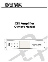
CKi Amplifier<br />
Owner’s Manual<br />
���<br />
������<br />
����������������������������������������
Intended to alert the user to the presence of uninsulated “dangerous voltage” within the product’s enclosure that<br />
may be of sufficient magnitude to constitute a risk of electric shock to persons.<br />
Intended to alert the user of the presence of important operating and maintenance (servicing) instructions in the literature<br />
accompanying the product.<br />
CAUTION: Risk of electrical shock — DO NOT OPEN!<br />
CAUTION:To reduce the risk of electric shock, do not remove cover. No user serviceable parts inside. Refer servicing to<br />
qualified service personnel.<br />
WARNING:To prevent electrical shock or fire hazard, do not expose this appliance to rain or moisture. Before using this<br />
appliance, read the operating guide for further warnings.<br />
Este símbolo tiene el propósito, de alertar al usuario de la presencia de “(voltaje) peligroso” sin aislamiento dentro de<br />
la caja del producto y que puede tener una magnitud suficiente como para constituir riesgo de descarga eléctrica.<br />
Este símbolo tiene el propósito de alertar al usario de la presencia de instruccones importantes sobre la operación y<br />
mantenimiento en la información que viene con el producto.<br />
PRECAUCION: Riesgo de descarga eléctrica ¡NO ABRIR!<br />
PRECAUCION: Para disminuír el riesgo de descarga eléctrica, no abra la cubierta. No hay piezas útiles dentro. Deje todo<br />
mantenimiento en manos del personal técnico cualificado.<br />
ADVERTENCIA: Para evitar descargas eléctricas o peligro de incendio, no deje expuesto a la lluvia o humedad este aparato<br />
Antes de usar este aparato, Iea más advertencias en la guía de operación.<br />
Ce symbole est utilisé dans ce manuel pour indiquer à l’utilisateur la présence d’une tension dangereuse pouvant être<br />
d’amplitude suffisante pour constituer un risque de choc électrique.<br />
Ce symbole est utilisé dans ce manuel pour indiquer à l’utilisateur qu’il ou qu’elle trouvera d’importantes instructions<br />
concernant l’utilisation et l’entretien de l’appareil dans le paragraphe signalé.<br />
ATTENTION: Risques de choc électrique — NE PAS OUVRIR!<br />
ATTENTION:Afin de réduire le risque de choc électrique, ne pas enlever le couvercle. Il ne se trouve à l’intérieur aucune<br />
pièce pouvant être reparée par l’utilisateur. Confiez I’entretien et la réparation de l’appareil à un réparateur agréé.<br />
AVERTISSEMENT:Afin de prévenir les risques de décharge électrique ou de feu, n’exposez pas cet appareil à la pluie ou<br />
à l’humidité.Avant d’utiliser cet appareil, lisez attentivement les avertissements supplémentaires de ce manuel.<br />
Dieses Symbol soll den Anwender vor unisolierten gefährlichen Spannungen innerhalb des Gehäuses warnen, die von<br />
Ausreichender Stärke sind, um einen elektrischen Schlag verursachen zu können.<br />
Dieses Symbol soll den Benutzer auf wichtige Instruktionen in der Bedienungsanleitung aufmerksam<br />
machen, die Handhabung und Wartung des Produkts betreffen.<br />
VORSICHT: Risiko — Elektrischer Schlag! Nicht öffnen!<br />
VORSICHT: Um das Risiko eines elektrischen Schlages zu vermeiden, nicht die Abdeckung enfernen. Es befinden sich keine<br />
Teile darin, die vom Anwender repariert werden könnten. Reparaturen nur von qualifiziertem Fachpersonal durchführen<br />
lassen.<br />
ACHTUNG: Um einen elektrischen Schlag oder Feuergefahr zu vermeiden, sollte dieses Gerät nicht dem Regen oder<br />
Feuchtigkeit ausgesetzt werden.Vor Inbetriebnahme unbedingt die Bedienungsanleitung lesen.
Important Safety Instructions<br />
WARNING: When using electrical products, basic cautions should always be followed, including the following:<br />
1. Read these instructions.<br />
2. Keep these instructions.<br />
3. Heed all warnings.<br />
4. Follow all instructions.<br />
5. Do not use this apparatus near water.<br />
6. Clean only with a dry cloth.<br />
7. Do not block any of the ventilation openings. Install in accordance with manufacturer’s instructions.<br />
8. Do not install near any heat sources such as radiators, heat registers, stoves or other apparatus (including<br />
amplifiers) that produce heat.<br />
9. Do not defeat the safety purpose of the polarized or grounding-type plug. A polarized plug has two blades with one<br />
wider than the other. A grounding type plug has two blades and a third grounding plug. The wide blade or third<br />
prong is provided for your safety. If the provided plug does not fit into your outlet, consult an electrician for<br />
replacement of the obsolete outlet.<br />
10. Protect the power cord from being walked on or pinched, particularly at plugs, convenience receptacles, and the<br />
point they exit from the apparatus.<br />
11. Only use attachments/accessoriegs provided by the manufacturer.<br />
12. Use only with a cart, stand, tripod, bracket, or table specified by the manufacturer or sold with the apparatus. When<br />
a cart is used, use caution when moving the cart/apparatus combination to avoid injury from tip-over.<br />
13. Unplug this apparatus during lightning storms or when unused for long periods of time.<br />
14. Refer all servicing to qualified service personnel. Servicing is required when the apparatus has been damaged in<br />
any way, such as power-supply cord or plug is damaged, liquid has been spilled or objects have fallen into the<br />
apparatus, the apparatus has been exposed to rain or moisture, does not operate normally, or has been dropped.<br />
15. Never break off the ground pin. Write for our free booklet “Shock Hazard and Grounding.” Connect only to a power<br />
supply of the type marked on the unit adjacent to the power supply cord.<br />
16. If this product is to be mounted in an equipment rack, rear support should be provided.<br />
17. Exposure to extremely high noise levels may cause a permanent hearing loss. Individuals vary considerably in<br />
susceptibility to noise-induced hearing loss, but nearly everyone will lose some hearing if exposed to sufficiently<br />
intense noise for a sufficient time. The U.S. Government’s Occupational and Health Administration (OSHA) has<br />
specified the following permissible noise level exposures:<br />
Duration Per Day In Hours Sound Level dBA, Slow Response<br />
8 90<br />
6 92<br />
4 95<br />
3 97<br />
2 100<br />
1 1/2 102<br />
1 105<br />
1/2 110<br />
1/4 or less 115<br />
According to OSHA, any exposure in excess of the above permissible limits could result in some hearing loss. Ear plugs or<br />
protectors to the ear canals or over the ears must be worn when operating this amplification system in order to prevent a<br />
permanent hearing loss, if exposure is in excess of the limits as set forth above. To ensure against potentially dangerous<br />
exposure to high sound pressure levels, it is recommended that all persons exposed to equipment capable of producing high<br />
sound pressure levels such as this amplification system be protected by hearing protectors while this unit is in operation.<br />
SAVE THESE INSTRUCTIONS !
1<br />
2<br />
3<br />
4<br />
5<br />
6<br />
7<br />
8<br />
a<br />
b<br />
c<br />
d<br />
How To Use This Manual . . . . . . . . . . . . . . . .p.2<br />
Introduction<br />
Conventions<br />
Installation . . . . . . . . . . . . . . . . . . . . . . . . . . . .p.3<br />
Unpacking<br />
Mounting<br />
Cooling Requirements<br />
Circuit Size Requirements<br />
PowerSave<br />
Maintenance<br />
Features Overview . . . . . . . . . . . . . . . . . . . . .p.7<br />
Front Panel<br />
Side Panel<br />
Rear Panel<br />
Modes . . . . . . . . . . . . . . . . . . . . . . . . . . . . . . .p.13<br />
Stereo<br />
Parallel<br />
Bridged<br />
Constant Voltage<br />
Operation . . . . . . . . . . . . . . . . . . . . . . . . . . . .p.15<br />
Power<br />
Input<br />
Output<br />
STO<br />
Safety . . . . . . . . . . . . . . . . . . . . . . . . . . . . . . . .p.21<br />
User Responsibility<br />
Speaker Protection<br />
Protection Circuitry<br />
NexSys <strong>Modules</strong> . . . . . . . . . . . . . . . . . . . . . . .p.25<br />
Introduction<br />
Installation<br />
Module Features<br />
Module Operation<br />
Service, Support & Warranty . . . . . . . . . . . . .p.34<br />
Support<br />
Contact <strong>Crest</strong><br />
Warranty<br />
Specifications . . . . . . . . . . . . . . . . . . . . . . . . . .p.35<br />
Constant Voltage . . . . . . . . . . . . . . . . . . . . . . .p.36<br />
Network Reference . . . . . . . . . . . . . . . . . . . .p.37<br />
Wire Gauge Chart . . . . . . . . . . . . . . . . . . . . .p.38<br />
Table Of Contents<br />
Contents<br />
Appendices<br />
p.1
1<br />
p.2<br />
How to use this manual<br />
Introduction<br />
Congratulations on your purchase of a <strong>Crest</strong> <strong>Audio</strong> CKi Intelligent Power Processing amplifier.<br />
Please read this manual carefully as it contains information vital to the unit’s safe operation.<br />
Also, please fill out and return the enclosed product registration card.<br />
CKi amplifiers represent a new level of value and flexibility never before offered to the contracting<br />
market. S Series models are designed to drive low impedance speaker loads while V<br />
Series models feature a unique front end circuit to provide directly coupled 70.7 volt outputs,<br />
eliminating the need for step-up transformers. X Series models feature transformer-isolated<br />
outputs for 100V operation (50V optional).<br />
Together, these amplifiers cover almost every conceivable installed or distributed sound<br />
power requirement.The CKi family is everything that you expect from <strong>Crest</strong> <strong>Audio</strong>.They are<br />
ruggedly built from high quality components, intelligently laid out, and possess comprehensive<br />
protection features.<br />
After-sale support is considered paramount at <strong>Crest</strong> <strong>Audio</strong>. For any assistance in the set-up<br />
or operation of this product please call <strong>Crest</strong> <strong>Audio</strong>’s Customer Service department or your<br />
local <strong>Crest</strong> <strong>Audio</strong> representative. Should you have any problems at all, or suggestions that<br />
may help us improve our products or service, please contact us.We encourage your participation<br />
in <strong>Crest</strong>’s future.<br />
FOR YOUR SAFETY, READ THE IMPORTANT PRECAUTIONS SECTION AS<br />
WELL AS THE INPUT, OUTPUT AND POWER CONNECTION SECTIONS<br />
OF THIS MANUAL.<br />
Conventions<br />
Warnings<br />
Procedures not to<br />
attempt.<br />
Issues or hazards to keep<br />
in mind when operating<br />
the equipment.<br />
Indicators<br />
What to look for on<br />
the equipment display.<br />
Alerts, indicators, or<br />
prompts that may<br />
appear.<br />
Tips<br />
Preferred methods.<br />
Helpful hints.<br />
Feature insights.<br />
®<br />
a<br />
+<br />
See<br />
See—refers to other sections of the manual containing supplementary information<br />
on the current topic or a related issue<br />
Note<br />
Note—supplementary feature information
What to do with the shipping carton<br />
/ Proper rack-mounting technique<br />
/ Keeping the amplifier cooled<br />
/ Supplying proper power<br />
/ Saving power<br />
/ Routine maintenance practices<br />
Installation 2<br />
Unpacking<br />
Mounting<br />
Cooling<br />
Requirements<br />
Circuit Size<br />
Requirements<br />
PowerSave<br />
Maintenance<br />
p.3
2<br />
p.4<br />
Installation<br />
Unpacking<br />
Upon unpacking, inspect the amplifier. If you find any damage, notify your supplier immediately.<br />
Only the consignee may institute a claim with the carrier for damage incurred during shipping.<br />
Be sure to save the carton and all packing materials. Should you ever need to ship the<br />
unit for any reason, use only the original factory packing. If the shipping carton is unavailable,<br />
contact <strong>Crest</strong> to obtain a replacement.<br />
Mounting<br />
<strong>Crest</strong> <strong>Audio</strong> CKi amplifiers are configured to a standard set-up at the factory.They are functional<br />
and ready to use ‘out of the box.’ All controls and input/output connections are clearly<br />
labeled. Units are shipped standard with a blank panel in the module bay.<br />
To set the amplifier up for basic usage:<br />
1. Mount the amplifier in a rack, remembering to allow for adequate access and cooling<br />
space.<br />
See - Cooling Requirements below for more information.<br />
2.Make input connections via the rear-panel Phoenix connector inputs.Make the connections<br />
to both inputs (Ch A and Ch B) for stereo operation, or connect to Ch A<br />
only for parallel or bridged mono configuration.<br />
See - Chapter 4 Modes for more information.<br />
3. Connect speakers to the output barrier strip. Be sure to make the correct output<br />
connections for stereo, parallel or bridged mono configuration.<br />
See - Chapter 5 Operation for more information.<br />
4. Make power connections, allowing for proper current draw.<br />
See - Chapter 5 Operation for more information on power considerations.<br />
5.Turn the front panel three-position AC switch to 'on', and bring up the rear panel<br />
gain attenuators to the desired level.<br />
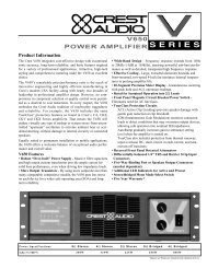
CKi Power Processing amplifiers are 2, 3 & 4-rack space units of 17 1/8" (437mm)<br />
depth that mount in a standard 19-inch rack. On 2 &3 rack space units, four front<br />
panel-mounting holes are provided. 4-rack space units have eight front panel-mounting<br />
holes.<br />
Rear mounting ears are also provided on all amplifiers for additional support, which<br />
is essential in non-permanent installations like mobile or touring sound systems, and<br />
recommended for permanent installations. (Distance from the back of the front rack<br />
ear to the center of the rear mounting ear holes is 16 5/8" / 422mm) Because of the<br />
cables and connectors on the rear panel, a right-angle or offset screwdriver or hex<br />
key will make it easier to fasten the rear mounting ears to the rails<br />
For replacement<br />
packaging, call <strong>Crest</strong><br />
<strong>Audio</strong>’s Customer Service<br />
Department directly.<br />
see—service and support<br />
Be certain that there is<br />
enough space around<br />
the the amplifier to<br />
allow the heated air to<br />
escape.When mounting<br />
in a rack, try to avoid<br />
using doors or covers<br />
on the front and rear of<br />
the enclosure; the<br />
exhaust air must not be<br />
impeded<br />
In racks with closed<br />
backs allow at least one<br />
standard-rack-space<br />
opening for every four<br />
amps.<br />
+<br />
a
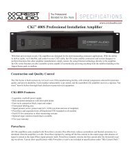
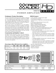
Front View<br />
Rear View<br />
Side View<br />
��<br />
���<br />
������<br />
������<br />
�������<br />
���<br />
������ ����<br />
����<br />
������ ������<br />
������������������<br />
��<br />
���<br />
���<br />
��<br />
���<br />
���<br />
�� ���<br />
����<br />
����<br />
�����<br />
���<br />
��<br />
�����<br />
���<br />
������<br />
���<br />
���<br />
���<br />
����������������������������������������<br />
�����������������<br />
������������������<br />
������������������<br />
���<br />
� �<br />
+<br />
+ +<br />
19” (483mm)<br />
17” (432mm)<br />
��� �����������������������<br />
����<br />
���� ����<br />
17.1” (435mm)<br />
���<br />
��<br />
���<br />
��<br />
������<br />
���<br />
�� ���<br />
��<br />
������<br />
���<br />
�������� �<br />
�� ���<br />
�� �<br />
��<br />
��<br />
����������������������������������������<br />
� �<br />
�������<br />
���<br />
���<br />
������<br />
���� ����<br />
+ +<br />
�����<br />
Installation 2<br />
���<br />
�������<br />
���<br />
���<br />
����<br />
7” (178mm)<br />
7” (178mm)<br />
7” (178mm)<br />
3.5” (89mm)<br />
5.25” (133mm)<br />
3.5” (89mm)<br />
5.25” (133mm)<br />
3.5” (89mm)<br />
5.25” (133mm)<br />
p.5
2<br />
p.6<br />
Installation<br />
Cooling Requirements<br />
CKi amplifiers use a forced-air cooling system to maintain a low, even operating temperature.Air<br />
drawn by a fan mounted behind the front panel enters through the front grille and<br />
the heated air exits through the side panel ports. On two an three space CKi amplifiers the<br />
fan will remain inactive until operating temperature rises to 45° C. One four space units the<br />
fan runs all the time. Make sure that there is enough space around the front of the amplifier<br />
to allow air to enter, and around the sides to allow the heated air to exit. System cooling<br />
needs must be considered before installation, and the system installer/designer should specify<br />
appropriate countermeasures, such as ventilation, air conditioning, etc. Refer to Appendix A<br />
for specific thermal emission figures.<br />
Note: If the amplifier is rack-mounted, do not use doors or covers on the front or rear<br />
without pressurizing the rack. Make sure that heated air can escape freely, and that there is<br />
no resistance to the intake of cool air. Intake and exhaust air must flow without restriction.<br />
Fan filters should be regularly cleaned and periodically replaced.<br />
Circuit Size Requirements<br />
CKi amplifier power requirements are rated at “idle,” 1/8th power (“typical” music conditions),<br />
1/3rd power, and maximum rated power.The maximum power current draw rating is<br />
limited by the amplifier's circuit breaker. Consult Appendix A for the current that each amplifier<br />
model will demand.AC mains voltage must be the same as that indicated on the rear of<br />
the amplifier. Damage caused by connecting the amplifier to improper AC voltage is not covered<br />
by any warranty.<br />
PowerSave<br />
All CKi amplifiers come standard with PowerSave circuitry.This effectively reduces current<br />
draw and thermal emissions to a minimum when the amplifier is at idle. PowerSave operates<br />
by cutting off the bias current to the output stage after absence of signal is sensed at the<br />
input.When signal presents itself, PowerSave instantly restores the bias current after the first<br />
positive-going waveform. Current draw specifications while PowerSave is active are included<br />
in specifications under "Idle Current Draw."<br />
Maintenance<br />
CKi amplifiers require little routine maintenance.<br />
When used in an extremely dusty or smoky environment, the unit should be periodically<br />
blown free (using compressed air) of any foreign matter that may have built up inside.<br />
When used in an environment where residue from smoke/fog machines is regularly present,<br />
the amplifier(s) should be periodically checked (by authorized <strong>Crest</strong> service personnel) for<br />
build-up of that residue.<br />
The filter in the front panel air intake grille should be periodically cleaned. Should the filter<br />
become permanently clogged or damaged, a replacement should be obtained through your<br />
<strong>Crest</strong> representative<br />
Users will not need to make any adjustments to the amplifier during its lifetime. Other than<br />
installing or replacing a NexSys module, there are no user-serviceable parts or adjustments<br />
that require opening the unit.<br />
Always turn off and<br />
disconnect the<br />
amplifier from the mains<br />
voltage before making<br />
audio connections. If<br />
possible, as an extra precaution,<br />
have the attenuators<br />
turned down during<br />
power-up.<br />
+
Controls and connectors<br />
/ Legend of panel symbols<br />
/ Air flow<br />
Features Overview 3<br />
Front Panel<br />
Side Panel<br />
Rear Panel<br />
p.7
3<br />
p.8<br />
Features Overview<br />
This chapter identifies the switches, indicators, connectors and functional components<br />
of all CKi amplifiers. Keep in mind that this chapter is only as an<br />
overview of the amplifier’s layout, and does not contain all the information necessary<br />
to effectively operate the CKi. For more detailed information on the<br />
items listed here, be sure to read this entire manual.<br />
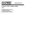
Front Panel - CKi 800s shown<br />
1 2 3 4 5 6 7<br />
��<br />
���<br />
������<br />
Front Panel<br />
�������<br />
���<br />
������ ����<br />
����<br />
������ ������<br />
1 Rack Mounting Ears<br />
Two holes (four on 4U amplifiers) are provided on each front mounting<br />
ear..<br />
2 3-Position Power Switch<br />
���<br />
������<br />
With this switch in the “up” position the amplifier is On.The middle<br />
position is Off and the lower position is marked Remote. When<br />
switched to Remote, the amplifier must be activated by the sequential<br />
turn on/turn off (STO) circuit.<br />
3 Protect LED<br />
If the amplifier enters any of its Protect modes, the output relay will<br />
open, and this LED will light.<br />
4Active LED<br />
The Active LED indicates the amplifier is turned on and the output<br />
relays have closed.<br />
5ACL LEDs<br />
Each channel has an ACL (Active Clip Limiting) LED. If a channel reaches<br />
the clipping point, this LED will light to show that the ACL circuit is<br />
active.<br />
����������������������������������������
Front Panel cont.<br />
6 Signal LEDs<br />
Each channel has a Signal LED.The intensity of the light varies with signal<br />
level – the stronger the input signal, the brighter the LED.<br />
7 Fan Grille & Filter<br />
A DC fan draws air into the amplifier though the removable dust filter.<br />
Do not block this intake! The fan operates only when the amplifier<br />
requires cooling. Fan filters are easy to remove and should be<br />
cleaned regularly to ensure optimum performance. Contact your<br />
<strong>Crest</strong> Representative to obtain replacement filters.<br />
Side Panel<br />
1 Exhaust Ports<br />
Heated air exits through the exhaust ports, on the sides of the amplifier<br />
chassis. Do not block these ports.<br />
Side View<br />
Warm Air<br />
1<br />
Features Overview 3<br />
Warm Air<br />
p.9
3<br />
p.10<br />
Features Overview<br />
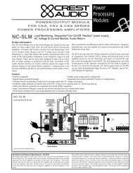
Rear Panel - CKi 100s shown<br />
1<br />
Rear Panel<br />
2<br />
������<br />
3<br />
������������������<br />
��<br />
���<br />
���<br />
��<br />
���<br />
���<br />
�� ���<br />
����<br />
����<br />
��<br />
�����<br />
�����<br />
���<br />
���<br />
���<br />
���<br />
����������������������������������������<br />
�����������������<br />
������������������<br />
������������������<br />
� �<br />
+<br />
+<br />
���<br />
+<br />
���<br />
��<br />
���<br />
��<br />
������<br />
���<br />
�� ���<br />
��<br />
������<br />
���<br />
�������� �<br />
��<br />
��<br />
���<br />
�<br />
��<br />
��<br />
��� �����������������������<br />
����<br />
���� ����<br />
1 Mains Breaker<br />
2U & 3U amplifiers have a push-type circuit breaker, while 4U units have<br />
a throw-switch style breaker. If the unit’s breaker trips repeatedly, the<br />
amplifier needs servicing.<br />
2 IEC Power Cord Connector<br />
On 2U amplifiers, a standard IEC power connector is located on the<br />
rear panel of amplifier.The connector accommodates a standard IEC line<br />
cord, included in the amplifier box. Should this cord need to be<br />
replaced, only a cord with the same current rating should be used. 3U<br />
& 4U units have a captive power cord.<br />
3AC Mains / Active LED indicators<br />
The AC mains yellow LED indicates that the amplifier is attached to a<br />
power source.The active green LED indicates that the amplifier has been<br />
turned on and is operating.<br />
4 Sequential turn on/off Connectors<br />
These connectors can be wired to a contact closure for remote turnon<br />
and to other CKi amplifiers for sequential turn-on (STO).<br />
5 Fault I/O Connector<br />
This output is a contact closure that can be used to report a fault condition<br />
(e.g. an open output relay) in the amplifier.<br />
6<br />
+<br />
� �<br />
�������<br />
���<br />
���<br />
������<br />
���� ����<br />
+ +<br />
4 5 7 12 13<br />
8<br />
9<br />
0<br />
¡<br />
�����<br />
���<br />
�������<br />
���<br />
���<br />
����<br />
Rear Panel Legend<br />
Ground Connected<br />
Ground Lifted<br />
Channel A stereo/parallel<br />
Bridged mono<br />
Channel B stereo/parallel<br />
Input Polarity<br />
Never connect a hot<br />
(red) output to ground<br />
or to another hot (red)<br />
output!<br />
a
Rear Panel cont.<br />
6 Output Connectors<br />
A barrier strip provides output connection terminals for two speakers<br />
operating in stereo or parallel, for a single speaker wired in a<br />
bridged mono configuration,or for constant voltage distribution.Bare<br />
wire or spade lugs may be used to make barrier strip connections.<br />
7 Ground Lift Switch<br />
This switch disconnects the audio ground from the chassis ground in<br />
the amplifier.<br />
8 Module Bay<br />
All CKi amplifiers possess a module bay configured to accept interchangeable<br />
plug-in modules. Your amplifier may have been factory<br />
configured with a module. Information on all CKi modules is available<br />
in this manual.<br />
See – Chapter 7 NexSys <strong>Modules</strong> for more information.<br />
9 Mode Select Switch<br />
This switch reconfigures the amplifiers outputs for stereo, parallel, or<br />
bridged operation..<br />
0 Input Attenuators<br />
Each channel has an attenuator knob to adjust the channel’s output<br />
from -∞ to maximum power.<br />
¡ Status LEDs<br />
The “Protect,” “Signal,” and “ACL” LED’s on the rear panel serve the<br />
same function as the front panel LED’s of the same names.The “IGM”<br />
LED will light if the amplifier’s IGM protection circuit engages.<br />
12<br />
13<br />
Input Connectors<br />
The CKi uses one 3-pin Phoenix connector per channel for balanced<br />
line-level audio input. These inputs can also be setup to accept an<br />
unbalanced signal.<br />
Gain (input sensitivity) Select Switch<br />
This switch sets the amplifier’s gain structure as constant sensitivity<br />
(0dB setting) or constant gain (x20 or x40 settings).<br />
Features Overview 3<br />
Do not adjust the<br />
mode selection switch<br />
while the amplifier is<br />
turned-on.<br />
In situations where an<br />
UNBALANCED signal<br />
is fed to the amp,<br />
it’s important to ground<br />
the unused input. If the<br />
inverting (-) input of an<br />
amp channel is left floating,<br />
the gain will drop<br />
by 3 dB.<br />
a<br />
+<br />
p.11
Choosing the appropriate mode<br />
/ Switching between operation modes<br />
/ Special considerations when using bridged mode<br />
/ Connecting to a constant voltage Line<br />
Stereo<br />
Parallel<br />
Bridged<br />
Constant<br />
Voltage<br />
Modes 4<br />
p.13
4<br />
p.14<br />
Modes<br />
Mode Selection<br />
The rear panel Mode Select Switch determines whether the amplifier is in<br />
stereo, parallel or bridged mono mode. Do not operate the Mode Select<br />
Switch with the amplifier on. See the next chapter on Operation for proper<br />
wiring in each mode.<br />
Stereo<br />
For stereo (dual channel) operation, turn the amplifier off and set the Mode<br />
Select Switch to the stereo position. In this mode, both channels operate independently<br />
of each other, with the input attenuators controlling each channel’s<br />
level. Thus, a signal at Channel A’s input produces an amplified signal at Channel<br />
A’s output, and the same for Channel B.<br />
Parallel<br />
For parallel (dual-channel/single input) operation, turn the amplifier off and set<br />
the Mode Select Switch to the parallel position; both amplifier channels will<br />
now be driven by the signal at Channel A’s input. No jumper wires are needed.<br />
Output connections are the same as in the stereo mode. In the parallel mode,<br />
only Channel A’s input is active; Channel B’s input is not in the circuit. Both<br />
attenuators remain active, permitting different levels for each channel. Power<br />
and other performance specifications are the same as in the stereo mode.<br />
Bridged Mono<br />
For Bridged (single channel/single input) operation, turn the amplifier off and<br />
set the Mode Select Switch to the Bridge position. This Mode straps both<br />
amplifier channels together, making a very powerful single channel. One channel<br />
“pushes” and the other “pulls” equally, effectively quadrupling the power of<br />
either channel alone.As in Parallel mode, signal is connected to Channel A. The<br />
nature of Bridged mode requires that both attenuators be set at the same<br />
level, preferably at 0dB attenuation.The speakers are connected only to the<br />
designated “+” output terminals. Use extreme caution when operating in the<br />
bridged mode, as potentially lethal voltage may be present at the output terminals.<br />
Unlike the stereo and parallel modes, in which one side of each output is<br />
grounded, both sides are hot in bridged mono mode. Channel A’s side is the<br />
same polarity as the input. Never ground either side of the speaker cable when<br />
the amplifier is in bridged mono mode; both sides are “hot.” If an output patch<br />
panel is used, all connections must be isolated from each other and from the<br />
panel.<br />
Constant Voltage<br />
CKi-V and CKi-X Series amplifiers are designed for use with distributed or<br />
constant voltage systems. These amplifiers can also be wired for Bridged Mono<br />
mode operation, however, bridging these models is usually undesirable, as the<br />
output will be approximately 140V (CKi-V) or 200V (CKi-X) There are, however,<br />
specific applications for this configuration. Contact <strong>Crest</strong> <strong>Audio</strong> Customer<br />
Service for more information if required.<br />
See – Appendix B for information on recommended distributed line impedance.<br />
������<br />
������<br />
����<br />
Connecting amplifier<br />
outputs to oscilloscopes<br />
or other test<br />
equipment while the<br />
amplifier is in bridged<br />
mode may damage both<br />
the amplifier and test<br />
equipment!<br />
Regardless of operating<br />
mode, NEVER connect<br />
amplifier outputs<br />
directly together!<br />
���<br />
��<br />
��������<br />
a<br />
a
Connecting the amplifier to AC power<br />
/ Proper signal paths<br />
/ Proper wiring schemes for output connectors<br />
/ Sequential turn on/off<br />
/ Additional operation considerations<br />
Operation 5<br />
Power<br />
Input<br />
Output<br />
STO<br />
p.15
5 Operation<br />
Power<br />
Unless otherwise specified when ordered, CKi Series amplifiers are shipped<br />
from the factory set to one of following voltage options:<br />
Inputs<br />
All CKi series amplifiers use 3-Pin Phoenix connectors for attaching input signals.<br />
Each connector is configured (from left to right) positive, negative,<br />
ground.<br />
p.16<br />
Option 1 US domestic<br />
Nominal 120Vac 60Hz for rated power output (safe operating range<br />
100 - 132Vac )<br />
Option 2 Export<br />
Nominal 230Vac 50Hz for rated power output (safe operating range<br />
200 - 264Vac )<br />
Input Phoenix Connectors<br />
����<br />
+ +<br />
Outputs<br />
Direct<br />
Direct (speaker) outputs are connected to CKi series amplifiers via the<br />
rear-panel terminal strips. Be sure to properly calculate the total<br />
impedance of all speakers connected to a direct output and to not<br />
exceed the minimum impedance rating of your CKi amplifier<br />
Constant Voltage<br />
For CKi-v and CKi-x models constant voltage (distributed) lines are<br />
connected to via the same rear-panel terminal strips. Be sure to properly<br />
calculate the total wattage demand of each constant voltage line<br />
and to not exceed the maximum output rating of your CKi amplifier.<br />
Output Barrier Strip<br />
� �<br />
+<br />
+<br />
���<br />
+<br />
See — the wiring diagrams on the next two pages for more information on<br />
connecting your CKi amplifier.<br />
In situations where an<br />
UNBALANCED sig+����<br />
nal is fed to the amp,<br />
it’s important to ground<br />
the unused input. If the<br />
inverting (-) input of an<br />
amp channel is left floating,<br />
the gain will drop<br />
by 3 dB.<br />
Very high current is<br />
available at the outputs.<br />
Please connect your<br />
output cable to the +<br />
and - terminals of each<br />
section precisely as<br />
shown.<br />
a
Stereo Mode<br />
Direct Outputs<br />
A<br />
Parallel Mode<br />
Direct Outputs<br />
A<br />
������<br />
������<br />
������������������<br />
��<br />
���<br />
���<br />
��<br />
���<br />
���<br />
�� ���<br />
������������������<br />
��<br />
���<br />
���<br />
��<br />
���<br />
���<br />
�� ���<br />
Bridged Mono Mode<br />
Direct Outputs<br />
������<br />
������������������<br />
��<br />
���<br />
���<br />
��<br />
���<br />
���<br />
�� ���<br />
����<br />
����<br />
��<br />
����<br />
����<br />
��<br />
����<br />
����<br />
��<br />
�����<br />
�����<br />
���<br />
���<br />
���<br />
���<br />
����������������������������������������<br />
�����������������<br />
������������������<br />
������������������<br />
� �<br />
+<br />
+<br />
���<br />
+<br />
���<br />
��<br />
���<br />
��<br />
������<br />
���<br />
�� ���<br />
��<br />
������<br />
���<br />
�������� �<br />
�� ���<br />
�� �<br />
��<br />
��<br />
��� �����������������������<br />
����<br />
���� ����<br />
�����<br />
�����<br />
���<br />
���<br />
���<br />
���<br />
����������������������������������������<br />
�����������������<br />
������������������<br />
������������������<br />
� �<br />
+<br />
+<br />
���<br />
+<br />
Operation 5<br />
����������� ��������<br />
������������<br />
������<br />
����<br />
� �<br />
����������� �����<br />
���� ������ ��������<br />
���������� ����<br />
B<br />
���<br />
��<br />
���<br />
��<br />
������<br />
���<br />
�� ���<br />
��<br />
������<br />
���<br />
�������� �<br />
�� ���<br />
�� �<br />
��<br />
��<br />
��� �����������������������<br />
����<br />
���� ����<br />
�����<br />
�����<br />
���<br />
���<br />
���<br />
���<br />
����������������������������������������<br />
�����������������<br />
������������������<br />
������������������<br />
� �<br />
+<br />
+<br />
���<br />
+<br />
� �<br />
�������<br />
���<br />
���<br />
������<br />
� �<br />
�������<br />
���<br />
���<br />
������<br />
���� ����<br />
+ +<br />
�����<br />
���� ����<br />
+ +<br />
�����<br />
���<br />
���<br />
�������<br />
���<br />
���<br />
����������� ��������<br />
������������<br />
������<br />
����<br />
� �<br />
����������� �����<br />
���� ������ ��������<br />
���������� ����<br />
B<br />
��� �����������������������<br />
����<br />
���� ����<br />
Bridged<br />
���<br />
��<br />
���<br />
��<br />
������<br />
���<br />
�� ���<br />
��<br />
������<br />
���<br />
�������� �<br />
�� ���<br />
�� �<br />
��<br />
��<br />
� �<br />
�������<br />
���<br />
���<br />
������<br />
���� ����<br />
+ +<br />
�����<br />
���<br />
����<br />
����<br />
����<br />
����<br />
+<br />
+<br />
�������<br />
���<br />
���<br />
����������� ��������<br />
������������<br />
������<br />
����<br />
� �<br />
����������� �����<br />
���� ������ ��������<br />
���������� ����<br />
����<br />
����<br />
����<br />
+<br />
�������<br />
���<br />
���<br />
Ch. B<br />
Ch. A<br />
Ch. A<br />
����<br />
����<br />
+<br />
Ch. A<br />
p.17
5<br />
p.18<br />
Operation<br />
Stereo Mode<br />
Constant Voltage Output (V & X Models only)<br />
Parallel Mode<br />
������<br />
������<br />
������������������<br />
��<br />
���<br />
���<br />
��<br />
���<br />
���<br />
�� ���<br />
������������������<br />
��<br />
���<br />
���<br />
��<br />
���<br />
���<br />
�� ���<br />
����<br />
����<br />
�����<br />
���<br />
��<br />
����<br />
����<br />
�����<br />
���<br />
��<br />
�����<br />
���<br />
���<br />
���<br />
����������������������������������������<br />
�����������������<br />
������������������<br />
������������������<br />
���<br />
� �<br />
+<br />
+ +<br />
������<br />
���<br />
���<br />
������<br />
�������� �<br />
��� �����������������������<br />
����<br />
���� ����<br />
CV Line Ch. A<br />
Constant Voltage Output (v & x Models only)<br />
�����<br />
���<br />
���<br />
���<br />
����������������������������������������<br />
�����������������<br />
������������������<br />
������������������<br />
���<br />
� �<br />
+<br />
+ +<br />
CV Line Ch. B<br />
����������� ��������<br />
������������<br />
������<br />
����<br />
� �<br />
����������� �����<br />
���� ������ ��������<br />
���������� ����<br />
���<br />
������<br />
���<br />
���<br />
������<br />
�������� �<br />
��<br />
���<br />
�� ���<br />
�� ���<br />
�� �<br />
��� �����������������������<br />
����<br />
���� ����<br />
CV Line Ch. A<br />
Removable Attenuator Knobs<br />
CV Line Ch. B<br />
The attenuator knobs can be removed and replaced with plugs that are<br />
shipped with the amplifier.The procedure for attenuator knob removal is as follows:<br />
1.With a small knife, remove the gray key cap of the attenuator knob<br />
revealing the inside nut.<br />
2. Using needle nose pliers or an appropriately sized nut driver, loosen<br />
the nut.<br />
3. Slide the attenuator knob off the shaft.<br />
4. Insert a regular screwdriver in the slotted end of the shaft and adjust<br />
attenuation to the desired level.<br />
5. Insert the blank plugs into the attenuator holes.<br />
���<br />
��<br />
���<br />
�� ���<br />
�� ���<br />
�� �<br />
��<br />
��<br />
��<br />
��<br />
��<br />
��<br />
��<br />
��<br />
� �<br />
�������<br />
���<br />
���<br />
������<br />
� �<br />
�������<br />
���<br />
���<br />
������<br />
���� ����<br />
+ +<br />
�����<br />
���� ����<br />
+ +<br />
�����<br />
���<br />
���<br />
�������<br />
���<br />
���<br />
����������� ��������<br />
������������<br />
������<br />
����<br />
� �<br />
����������� �����<br />
���� ������ ��������<br />
���������� ����<br />
���<br />
���<br />
���<br />
���� �<br />
����<br />
����<br />
����<br />
����<br />
����<br />
+<br />
+<br />
�������<br />
���<br />
���<br />
����<br />
����<br />
+<br />
Ch. B<br />
Ch. A<br />
Ch. A<br />
Ch.A - Knob still attached<br />
Ch. B - Knob replaced with plug<br />
��<br />
���<br />
�� ���<br />
��<br />
��<br />
���<br />
�<br />
��<br />
����<br />
��<br />
��<br />
��
Gain Select Switch<br />
The 3-position gain select switch on the rear panel to sets the overall gain of<br />
the amplifier.The left and right switch positions set the amplifier for constant<br />
gain of x20 (26 dB) or x40 (32 dB) respectively.The center position sets the<br />
amplifier for constant sensitivity. In this position, a 0dBu (0.775 VRMS) input<br />
signal will produce maximum power at the amplifier’s output.The standard<br />
factory setting is for x40 (32dB).The specifications for a specific CKi models<br />
in Appendix A contain more gain/sensitivity information.<br />
Signal Ground Lift Switch<br />
The signal source equipment should share the same AC ground as the amplifier(s).<br />
In some cases, however, particularly if an amplifier is being installed in<br />
an existing system, this may result in a ground loop, creating excessive 60Hz<br />
hum at the amplifier’s output. If this happens, slide the ground lift switch on<br />
the amplifier’s rear panel to the “open” (left) position. In this position, the signal<br />
ground is lifted from the chassis ground and is clamped to ± 0.6V. Do not<br />
lift the ground if the amplifier and the signal source equipment are not on the<br />
same AC ground! In a properly designed system, the amplifier should receive<br />
its ground from the AC line cord to ensure safety and minimize noise.<br />
Sequential Turn On/Off (STO)<br />
CKi amplifiers come standard with Sequential Turn-On/Turn-Off (STO) circuitry.When<br />
the amplifier front power switch is set to “remote,” a single<br />
SPDT toggle switch or two SPST momentary switches can be used to turn<br />
the amplifier on and off. Using the same switch(es), additional amplifiers can<br />
be turned on/off sequentially by daisy chaining the STO "Out" terminals of<br />
one amplifier to the STO "In" terminals of a subsequent amplifier.The standard<br />
turn-on delay time between amplifiers is approximately 100ms; turn-off<br />
delay time is 200ms. When using NexSys control with an amplifier equipped<br />
with an NxEthernet or NxCobraNet module, these standard turn-on and<br />
turn-off delay times may be modified in the control software.<br />
Standard Sequential Turn-On/Turn-Off Wiring<br />
For non-NexSys remote turn-on, a single SPDT toggle switch or two SPST<br />
momentary switches can be used. In either case, the switch(es) are wired to<br />
the “STO In” connector on the amplifier’s rear panel and the amplifier’s front<br />
panel power switch must be set to “Remote.” The switch(es) should be wired<br />
to close a connection between “Com” and “On” pins for turn-on, and<br />
between the “Com” and “Off” pins for turn-off. The diagram below illustrates<br />
the circuit:<br />
On<br />
Off<br />
������ ������<br />
������������������<br />
������������������<br />
�� �� ��� ���<br />
���� ����<br />
����� �����<br />
�� ��<br />
��� ���<br />
��� ���<br />
�� ��<br />
��� ���<br />
��� ���<br />
���� ����<br />
����� �����<br />
��� ���<br />
��� ���<br />
��� ���<br />
��� ���<br />
�� ��<br />
��� ���<br />
+ +<br />
�����������������������<br />
�����������������������<br />
Operation 5<br />
���<br />
�������<br />
���<br />
����<br />
���<br />
The shield on a balanced<br />
input line should<br />
be grounded at one end<br />
only (usually the sending<br />
end), and it must never<br />
be relied on to supply<br />
AC ground to the amplifier.<br />
When using NexSys<br />
control, hardwiring<br />
for manual switch<br />
closure between amplifiers<br />
should be used cautiously.<br />
If the switch closure<br />
output is wired up,<br />
it WILL cause the next<br />
amp to switch, regardless<br />
of which source<br />
(hardware switch or<br />
NexSys STO command)<br />
has initiated the command.<br />
a<br />
+<br />
p.19
5<br />
p.20<br />
Operation<br />
STO Daisy Chaining<br />
Any number of CKi amplifiers can be daisy-chained together for<br />
sequential turn-on.Wiring two amplifiers for STO is as simple as connecting<br />
the “On,” “Com” and “Off” pins of the “STO Out” connector<br />
on the first amplifier to the corresponding pins on the “STO In” connector<br />
on the second amplifier. Repeating this wiring scheme with subsequent<br />
amplifiers allows entire systems of CKi’s to be wired for STO.<br />
<strong>Modules</strong><br />
CKi amplifiers come standard with a blank panel fixed over the module bay.<br />
When a NexSys module is installed in this bay, connection to a network is<br />
made via a standard RJ-45 connector and CAT-5 Ethernet cable.<br />
Module Removal/Installation<br />
The amplifier must be switched off and unplugged from the AC mains<br />
supply before any module operation is undertaken. Two Phillips head<br />
screws secure the module/panel to the chassis.The module is connected<br />
electrically to the amplifier with a single multi-pin ribbon cable.Once<br />
unscrewed from the chassis, unplugging the module from this ribbon<br />
cable frees the module for removal.To insert a module, simply reverse<br />
this procedure.<br />
See – Chapter 7 NexSys <strong>Modules</strong> for more information<br />
Module Bay with Blank Panel Installed<br />
�����<br />
���<br />
� �<br />
+<br />
+ +<br />
�����������������<br />
���<br />
���<br />
���<br />
������<br />
���<br />
���<br />
������<br />
�������� �<br />
��� �����������������������<br />
����<br />
���� ����<br />
� �<br />
�������<br />
���<br />
���<br />
������<br />
���� ����<br />
+ +<br />
Module Bay with Nx Ethernet Module Installed<br />
�����<br />
����������������������������������������<br />
������������������<br />
������������������<br />
����������������������������������������<br />
���<br />
� �<br />
+<br />
+ +<br />
������������������<br />
������������������<br />
�����������������<br />
���<br />
���<br />
���<br />
��<br />
�� ���<br />
�� ���<br />
�� �<br />
��� �����������������������<br />
����<br />
���� ����<br />
���<br />
���<br />
��<br />
��<br />
��<br />
��<br />
�����<br />
���<br />
�������<br />
���<br />
���<br />
����������� ��������<br />
������������<br />
������<br />
����<br />
� �<br />
����������� �����<br />
���� ������ ��������<br />
���������� ����<br />
���<br />
������<br />
���<br />
���<br />
������<br />
�������� �<br />
��<br />
���<br />
�� ���<br />
�� ���<br />
�� �<br />
��<br />
��<br />
��<br />
��<br />
� �<br />
�������<br />
���<br />
���<br />
������<br />
���� ����<br />
+ +<br />
�����<br />
���<br />
����<br />
�������<br />
���<br />
���<br />
����<br />
����<br />
����<br />
On<br />
Off<br />
������<br />
������<br />
������������������<br />
��<br />
���<br />
���<br />
��<br />
���<br />
���<br />
�� ���<br />
������������������<br />
��<br />
���<br />
���<br />
��<br />
���<br />
���<br />
�� ���<br />
����<br />
����<br />
�����<br />
���<br />
��<br />
����<br />
����<br />
�����<br />
���<br />
��<br />
�����<br />
���<br />
���<br />
���<br />
���<br />
�����<br />
���<br />
���<br />
���<br />
���<br />
���������������������������<br />
�������<br />
�������<br />
�����<br />
�<br />
���������������������������<br />
�������<br />
�������<br />
�����<br />
�<br />
���<br />
+<br />
+ +<br />
������������������<br />
���<br />
+<br />
+ +<br />
������������������<br />
Standard CKi Power<br />
Processing amplifiers<br />
come with a blank panel<br />
installed in the Network<br />
bay.The amplifier must<br />
not be operated without<br />
a Network module or<br />
blank panel in place.<br />
Removable modules<br />
contain static-sensitive<br />
devices; handle modules<br />
only at static-safe workstations!<br />
a<br />
a
The owner’s role in amplifier safety<br />
/ Protecting your speakers<br />
/ Description of protection features<br />
Safety 6<br />
User<br />
Responsibility<br />
Speaker<br />
Protection<br />
Protection<br />
Features<br />
p.21
6<br />
p.22<br />
Safety<br />
User Responsibility<br />
Your CKi Series amplifier is very powerful and can be potentially dangerous to<br />
loudspeakers and operators alike. It is your responsibility to read all precautions<br />
and make sure that the amplifier is installed, wired, and operated properly<br />
as instructed in this manual.<br />
Many loudspeakers can be easily damaged or destroyed by overpowering, especially<br />
with the high power available from a bridged amplifier. Always be aware<br />
of the speaker’s continuous and peak power capabilities. <strong>Crest</strong> <strong>Audio</strong> is not<br />
responsible for damage to loudspeakers for any reason.<br />
Speaker Protection<br />
All loudspeakers have electrical, thermal and physical limits which must be<br />
observed to prevent damage or failure. Too much power, severely clipped wave<br />
forms, low frequencies applied to high frequency drivers and DC voltage can all<br />
be fatal to cone and compression drivers. <strong>Crest</strong> <strong>Audio</strong> CKi Series amplifiers<br />
automatically protect speakers from DC voltages and subsonic signals.<br />
Be sure that the low and mid bands of an electronic crossover are connected<br />
to the correct amplifiers and drivers, and not accidentally connected to those<br />
for a higher frequency band. The amplifier’s clipping point is its maximum peak<br />
output power, and some of the higher-powered CKi Series amplifiers can deliver<br />
more power than many speakers can safely handle. Be sure the peak power<br />
capability of the amplifier is not excessive for your speaker system.<br />
To ensure the speakers never receive excessive power and that the amplifier<br />
never clips, use a properly adjusted external limiter (or a compressor with a<br />
ratio of 10:1 or higher) to control power output; in systems with active electronic<br />
crossovers, use one for each frequency band. The clip limiter will automatically<br />
limit the duration of squared-off, continuous wave forms applied to<br />
the speakers.The amplifier will, however, allow normal musical transient bursts<br />
to pass. When the amplifier does clip, it is at its maximum output power.<br />
Some speaker systems are packaged with processors that have power limiting<br />
circuits and should not require additional external limiting. Fuses may also be<br />
used to limit power to speaker drivers, although as current-limiting rather than<br />
voltage limiting devices. Some poor quality fuses have a significant series resistance<br />
that could degrade the amplifier’s damping of the speaker’s motion and<br />
may even deteriorate the system’s sound quality. If you elect to use fuses,<br />
check with the speaker manufacturer to determine the proper current rating<br />
and time lag required.<br />
Do not drive any low frequency speaker enclosure with frequencies lower than<br />
its own tuned frequency; the reduced acoustical damping could cause a ported<br />
speaker to bottom out even at moderate power. Consult the speaker system<br />
specifications to determine its frequency limits.<br />
The wire gauge charts in Appendix D will assist you in determining the optimum<br />
copper wire gauge for speaker cables in direct output systems. Speaker<br />
cable resistance robs amplifier power in two ways: through power lost directly<br />
to resistance (often referred to as I2R loss), and through increased total load<br />
resistance, which decreases the amount of power available from the amplifier.<br />
Appendix D gives cable length figures in feet/AWG wire gauges and in metric<br />
values.
Protection Features<br />
CKi Series amplifiers incorporate several circuits to protect both themselves<br />
and loudspeakers. <strong>Crest</strong> <strong>Audio</strong> has attempted to make the amplifiers as foolproof<br />
as possible by making them immune to short and open circuits, mismatched<br />
loads, DC voltage and overheating. If a channel goes into ACL gain<br />
reduction mode, the speaker load will remain connected but clipping percentage<br />
or output power will be instantly reduced. When a problem occurs that<br />
causes a channel to go into a protection mode, the Protect LED for that<br />
channel will glow. DC voltage on the output, excessive subsonic frequencies<br />
or thermal overload will cause the channel’s output relay to open, disconnecting<br />
the speaker load until the condition is corrected.<br />
Automatic Clip Limiting (ACL)<br />
Any time a channel is driven into continuous clipping, the clip limiter<br />
circuit will reduce the channel gain to a level just slightly into clipping,<br />
which protects the speakers against the damaging,high power, continuous<br />
square waves. Situations that may activate the clip limiter include<br />
uncontrolled feedback, oscillations, and improper equipment setting<br />
or a malfunction upstream from the amplifier. Normal program transients<br />
will not trigger the clip limiter; only steady, excessive clipping<br />
will. The ACL LED will glow brightly and continuously when limiting<br />
occurs.<br />
IGM Impedance Sensing<br />
CKi Series amplifiers feature innovative circuitry that allows safe operation<br />
into any load. When an amplifier sees a load that overstresses<br />
the output stage, the Instantaneous Gain Modulation (IGM) circuit<br />
adjusts the channel gain to a safe level. This method of output stage<br />
protection is far superior to the conventional, brute force-type limiting<br />
found on other amplifiers. The IGM circuit is sonically transparent<br />
in normal use and unobtrusive when activated.<br />
Thermal Protection<br />
The internal fan will keep the amplifier operating well within its<br />
intended temperature range under normal conditions. If a channel’s<br />
heat sink temperature reaches 75°C (which may indicate an obstructed<br />
air supply), that channel will independently protect itself by disconnecting<br />
its load and shutting down until it has cooled. During this<br />
time, the Protect LED will light,the Active LED will extinguish and the<br />
cooling fan will run at its highest speed.<br />
Short Circuit<br />
If an output is shorted, the IGM and thermal circuits will automatically<br />
protect the amplifier. The IGM circuit senses the short circuit as an<br />
extremely stressful load condition and attenuates the signal, protecting<br />
the channel’s output transistors from over-current stress. If the<br />
short circuit remains, the channel will eventually thermally protect<br />
itself by disconnecting the load.<br />
DC Voltage Protection<br />
If an amplifier channel detects DC voltage or subsonic frequencies at<br />
a channel output,the respective output relay will immediately open to<br />
prevent loudspeaker damage.The Protect DC LED will light.<br />
Safety 6<br />
p.23
6<br />
p.24<br />
Safety<br />
Turn-On/Turn-Off Protection<br />
At power-up, the amplifier stays in the protect mode with outputs disconnected<br />
for about six seconds, while the power supplies charge and<br />
stabilize. While the output relays are open, the ACL LEDs will light.<br />
When the power is turned off, the speaker loads immediately disconnect<br />
so that no thumps or pops are heard.<br />
Auto Ramp Signal Control<br />
Whenever a CKi Series amplifier powers up or comes out of a protect<br />
mode, the Auto Ramp circuit activates. While the speakers are disconnected,<br />
the Auto Ramp circuit fully attenuates the signal. After the output<br />
relay closes, the signal slowly and gradually raises up to its set level.<br />
PowerSave<br />
All CKi amplifiers come standard with PowerSave circuitrywhich<br />
reduces current draw and thermal emissions at idle. PowerSave operates<br />
by cutting off the bias current to the output stage when signal is no<br />
longer sensed at the input.When signal appears,bias current is instantl;y<br />
restored after the first positive-going waveform. Current draw specifications<br />
while PowerSave is active are included in specifications under<br />
"Idle Current Draw."<br />
NexSys Fault Monitoring<br />
A CKi equipped with an NxEthernet or NxCobraNet module and connected<br />
to a NexSys network will report fault conditions to the PC controlling<br />
the network. If a networked amplifier enters ACL or IGM or<br />
experiences a thermal, DC voltage, or short circuit fault, the fault condition<br />
will be reported the PC interface.This allows easy monitoring of<br />
amplifier operating conditions across a large or widespread network<br />
from a single location.
General module information<br />
/ Installing a module<br />
/ Individual module features<br />
/ Using a module<br />
/ Setting amplifier IDs<br />
/ Amplifier monitoring via modules<br />
NexSys <strong>Modules</strong> 7<br />
Overview<br />
Installation<br />
Features<br />
Operation<br />
Amplifier ID<br />
Condition<br />
Monitoring<br />
p.25
7<br />
p.26<br />
NexSys <strong>Modules</strong><br />
Overview<br />
The extended capabilities of CKi amplifiers are reached when connected to a<br />
NexSys amplifier network via a NexSys module.These modules reside in the<br />
CKi’s module bay and provide control, monitoring, and signal processing features.This<br />
chapter covers the installation of NexSys modules as well as information<br />
concerning computer control of a NexSys system. For more information<br />
about controlling a system with NexSys refer to the NexSys System<br />
Manual<br />
Module Installation<br />
There are two modules through which a CKi amplifier can be connected to a<br />
NexSys network – the NxEthernet Module and NxCobranet Module.<br />
Although they have different feature sets, they both serve the networking function.<br />
Because of this, they are collectively referred to as “network modules.”<br />
The installation procedure for both is the same.<br />
1. Remove the blank panel covering the CKi’s module bay by removing<br />
the screws on either side of the panel.Save these screws,as they will be<br />
needed for fastening the network module.<br />
2. Inside the exposed module bay you should see the ribbon cable connector<br />
on the amplifier’s circuit board. Note of the way the connector<br />
is keyed, and position the ribbon cable to match. Insert the cable into<br />
the connector, with the opposite end hanging out of the module bay.<br />
3.Position the network module right side up.Connect the exposed end<br />
of the ribbon cable to the connector on the module, again taking note<br />
of the keying of the connectors.<br />
4. Slide the module into the bay, and fasten it to the CKi’s chassis with<br />
the screws removed in Step #1.<br />
������<br />
������������������<br />
��<br />
���<br />
���<br />
��<br />
���<br />
���<br />
�� ���<br />
����<br />
����<br />
�����<br />
���<br />
��<br />
�����<br />
���<br />
���<br />
���<br />
����������������������������������������<br />
�����������������<br />
������������������<br />
������������������<br />
� �<br />
+<br />
+<br />
���<br />
+<br />
���<br />
��<br />
���<br />
��<br />
������<br />
���<br />
�� ���<br />
��<br />
������<br />
���<br />
�������� �<br />
�� ���<br />
�� �<br />
��<br />
��<br />
��� �����������������������<br />
����<br />
���� ����<br />
����������� ��������<br />
������������<br />
������<br />
����<br />
� �<br />
����������� �����<br />
���� ������ ��������<br />
���������� ����<br />
����<br />
����<br />
� �<br />
�������<br />
���<br />
���<br />
������<br />
���� ����<br />
+ +<br />
�����<br />
���<br />
�������<br />
���<br />
���<br />
����
Module Features<br />
This following pages describe the buttons, indicators, connectors and functional<br />
components that are relevant to the two NexSys modules. These features<br />
exist on both the NxEthernet and NxCobranet <strong>Modules</strong>. Features<br />
specific to the NxCobranet Module are discussed later in this chapter.<br />
����������� ��������<br />
������������<br />
������<br />
����<br />
� �<br />
����������� �����<br />
���� ������ ��������<br />
���������� ����<br />
1 2 3 4 5 6 7 8 9 0 ¡<br />
1 4-character Display<br />
The LED display shows the value of the current parameter for the<br />
function chosen. The selected Function is indicated by the corresponding<br />
LED.<br />
2 Edit Button<br />
Enables and disables editing of a function parameter. When pressed,<br />
the value in the display will flash, indicating that edit mode has been<br />
entered.The value can now be adjusted using the increment and decrement<br />
buttons. Pressing Edit again will register the value and stop the<br />
flashing of the display.<br />
3 Select Button<br />
When a function parameter exists for both channels independently<br />
(e.g. Gain,Temperature), this button changes between the parameter<br />
values for Channel A and Channel B. This button is also used to select<br />
parameters within a given function.<br />
4 Function Button<br />
This button scrolls through the functions that can be controlled from<br />
the module panel including: I.P. Address,Amp ID, Gain,Temperature,<br />
AC Line Voltage. As each is selected, the corresponding LED wil light<br />
and the appropriate function parameter will appear in the display.<br />
5 Increment/Decrement Buttons<br />
When the module is in edit mode and the value in the display is flashing,<br />
the increment and decrement buttons will adjust the value.<br />
6 Function LEDs<br />
Each of the main functions has a corresponding LED. When a function<br />
is selected, this LED will light to identify the selection.Some secondary<br />
functions do not have an associated LED, so no LED will light<br />
when these functions are selected.<br />
NexSys <strong>Modules</strong> 7<br />
����<br />
����<br />
Not all function parameters<br />
can be adjusted<br />
(e.g.AC Line<br />
Voltage,Temperature,<br />
etc.) as they are output<br />
values only.<br />
+<br />
p.27
7<br />
p.28<br />
NexSys <strong>Modules</strong><br />
����������� ��������<br />
������������<br />
������<br />
����<br />
� �<br />
����������� �����<br />
���� ������ ��������<br />
���������� ����<br />
1 2 3 4 5 6 7 8 9 0 ¡<br />
7 Fault LEDs<br />
Each channel has a fault LED on the module panel. If one or more of a<br />
channel’s faults is triggered,this LED will illuminate. A fault code will also<br />
appear in the display.<br />
8 Mute LEDs<br />
Each channel has a mute LED that will illuminate if the channel is muted<br />
through the control software.<br />
9 Option Window<br />
This space, shipped standard with a blanking panel installed, can accommodate<br />
various add-on options to the network module including the<br />
NxDSP signal processing module.<br />
0 RJ-45 Network Connector<br />
The Neutrik ® EtherCon ® ruggedized RJ-45 connector allows connection<br />
of the CKi amplifier to an Ethernet network.The jack accommodates<br />
a standard male RJ-45 connector or the male EtherCon ® connector.<br />
¡ Data & Link LEDs<br />
The Data LED will flash when data packets are being sent or received<br />
by the module.<br />
The Link LED will light when the module detects that it is connected<br />
to an Ethernet network.<br />
NxCobranet<br />
The NxCobranet module varies in appearance only in the fact that<br />
above the RJ-45 connection NxCobraNet appears instead of<br />
NxEthernet.<br />
����<br />
����
Module Operation<br />
The following pages contain information on how to operate the NxEthernet<br />
and NxCobraNet modules. The NexSys functions that can be controlled<br />
from the amplifier’s rear panel will be explained. After working through this<br />
section, you should have an understanding of the network modules’ operation<br />
through hardware. For more on software control of the modules’ features,<br />
see the NexSys Manual.<br />
The instructions in this chapter assume that a module has been mounted in<br />
the CKi amplifier and the user has a working knowledge of the module’s<br />
control panel layout.<br />
Making Network Connections<br />
The Network modules are connected to the network via standard<br />
CAT-5 Ethernet cabling using and RJ-45 connector. For a more robust<br />
connection, use a Neutrik ® EtherCon ® connector. All CKi network<br />
modules are equipped to accommodate this more robust solution.<br />
When the cable has been physically connected to the module and to<br />
an active network device, the “Link” LED will illuminate.<br />
Setting IP Addresses<br />
Press the Function button until the LED next to I.P.Address illuminates.<br />
Once the function has been chosen, depressing the Select button will<br />
scroll through the four octets of the I.P. Address.The position of the<br />
decimal point in the numeric display designates which octet has been<br />
selected. If the decimal point is to the left of all three digits, then the<br />
first octet is being displayed. If the decimal is between the first and<br />
second digit, the second octet is being displayed and so on.<br />
Once the appropriate octet has been selected, press the Edit button.<br />
The octet value will begin flashing.Press the increment and decrement<br />
buttons to change the octet value.There are 256 possible values for<br />
each octet, ranging from 0 to 255. Once the correct value has been<br />
reached, press the Edit button again to register the value and exit edit<br />
mode. If another octet value must be changed, select it using the<br />
Select button and repeat the editing procedure.<br />
Setting the I.P.Address to 000.000.000.000 will enable DHCP for this<br />
amplifier. Under this setting a connected DHCP server will dymanically<br />
assign an I.P.Address to the amplifier.<br />
Setting Amplifier ID<br />
Use the Function button to choose Amp ID. Each Amp ID is composed<br />
of two, two-digit hexadecimal values (see Appendix C for more information<br />
on Hex Numbering).The upper two digits (the High Value) and<br />
the lower two digits (the Low Value) can be independently adjusted.<br />
For this function, the Select button toggles between these two values.<br />
Select a value for adjustment, and press Edit.The selected portion of<br />
the ID will flash, and the increment and decrement keys can now be<br />
used to adjust the value.<br />
An amplifier’s I.P.Address can be used to designate an amp in a network,<br />
however Amp ID is more useful for designation, particularly<br />
when DHCP is being used.<br />
NexSys <strong>Modules</strong> 7<br />
��������<br />
For instructions on<br />
I.P.Addresses, designing<br />
and setting up a<br />
complete network,<br />
please see Appendix C:<br />
Network Examples<br />
�����������<br />
���� ������ ��������<br />
����<br />
����<br />
������������<br />
������<br />
����<br />
�����������<br />
����������<br />
+<br />
p.29
7<br />
p.30<br />
NexSys <strong>Modules</strong><br />
Amplifier IDs can remain fixed even if the I.P.Address changes, making<br />
the amplifier’s settings and operating conditions easier to track.<br />
Additionally, creative use of the High and Low Values in the Amp ID can<br />
provide even more information about an amplifier. Since the two values<br />
can be adjusted independently,the High Value could be used to designate<br />
a group of amplifiers, while the Low Value would identify specific<br />
amplifiers in that group.<br />
Adjusting Gain<br />
Use the Function button to choose Gain. In this mode, the Select button<br />
chooses between Channel A and B.With the proper channel selected,<br />
press the Edit button.The increment and decrement buttons will now<br />
adjust the channel’s gain. If the channel has been muted by NexSys, the<br />
first press of either the increment or decrement will bring the channel<br />
out of mute and return its previous value.Subsequent presses will adjust<br />
the gain value. Once the gain has been adjusted,pressing the “Edit” button<br />
again will lock in the value and the display will stop flashing.<br />
Gain values are listed in dB, from 0 (unity) to –80. The setting of the<br />
amplifier’s attenuators will also affect the overall gain. The attenuators<br />
are positioned after the NexSys gain control in the amp’s gain structure<br />
resulting in an additive attenuation value. For example, if an attenuator<br />
is set to –6dB,and the NexSys gain for that channel is set to –10dB,the<br />
amplifier’s overall gain will be 16dB below the amplifier’s maximum<br />
ouput.<br />
Condition Monitoring<br />
These functions do not make use of the Edit and increment/decrement buttons.They<br />
simply provide information concerning the amplifier’s operating condition.<br />
Temperature<br />
Use the Function button to choose Temperature.The internal ambient<br />
temperature of the amplifier will be displayed with a designation of “F”<br />
for degrees Fahrenheit or “C” for degrees Celsius.To change the units<br />
that the temperature is displayed in, press the Select button.<br />
AC Line Voltage<br />
Use the Function button to choose AC Voltage. The AC line voltage will<br />
be displayed.<br />
�����������<br />
���� ������ ��������<br />
Amplifier channels can<br />
not be muted from the<br />
network module controls.<br />
Channels can only<br />
be unmuted using the<br />
procedure described.<br />
������������<br />
������<br />
����<br />
�����������<br />
����������<br />
+
NexSys <strong>Modules</strong> 7<br />
p.31
When to get support<br />
/ Ways to contact <strong>Crest</strong> <strong>Audio</strong><br />
Service, Support & Warranty 8<br />
Support<br />
Contact <strong>Crest</strong><br />
Warranty<br />
p.33
8<br />
p.34<br />
Service, Support & Warranty<br />
Support<br />
In the unlikely event that your amplifier develops a problem, it must be<br />
returned to an authorized distributor, service center or shipped directly<br />
to our factory. Because of the complexity of the design and the risk<br />
of electrical shock, all repairs must be attempted only by qualified technical<br />
personnel.<br />
If the unit needs to be shipped back to the factory, it must be sent in its<br />
original carton. If improperly packed, the unit may be damaged.<br />
To obtain service, contact your nearest <strong>Crest</strong> <strong>Audio</strong> Service Center,<br />
Distributor, Dealer, or any of the worldwide <strong>Crest</strong> <strong>Audio</strong> offices. For<br />
those with Internet access, please visit the <strong>Crest</strong> <strong>Audio</strong> web site.<br />
Contact <strong>Crest</strong><br />
Customer Service<br />
Phone 201.475.4600 USA<br />
Fax 201.475.4677 USA<br />
Email customerserve@crestaudio.com<br />
Technical Support<br />
Phone 201.475.4600 USA<br />
Fax 201.475.4632 USA<br />
Email techserve@crestaudio.com<br />
Web Site<br />
www.crestaudio.com<br />
Postal Mail<br />
<strong>Crest</strong> <strong>Audio</strong> Inc.<br />
16-00 Pollitt Drive<br />
Fair Lawn, NJ 07410 USA<br />
Warranty<br />
Your <strong>Crest</strong> <strong>Audio</strong> Amplifier is covered against defects in material and<br />
workmanship. Refer to the warranty card provided with this manual for<br />
more details.<br />
For replacement<br />
packaging, call <strong>Crest</strong><br />
<strong>Audio</strong>’s Customer Service<br />
+
CKi Series S Models<br />
Specifications a<br />
CKi 100S CKi 200S CKi 400S CKi 800S CKi 800-2S CKi 1200S CKi 1600S<br />
Stereo Power per channel<br />
(both channels driven) 2Ω<br />
N/A N/A N/A N/A 800W 1100W 1100W<br />
4Ω 75W 150W 300W 600W 600W 900W 1100W<br />
8Ω 50W 100W 200W 400W 400W 600W 800W<br />
Bridge Power 4Ω N/A N/A N/A N/A 1600 2200 2800<br />
8Ω 100 200 400 800 800 1800 2200<br />
Minimum Load Impedance<br />
Maximum output RMS<br />
Voltage Swing<br />
22V 32V 45V 64V 64V 78V 90V<br />
Frequency Response 1W @ 8Ω<br />
10Hz-20kHz, -2dB @ 148 kHz<br />
Power Bandwidth @<br />
rated 4Ω power<br />
10Hz-20kHz, +0/-0.2dB<br />
Damping Factor (8Ω) 300:1 300:1 300:1 400:1 400:1 400:1 400:1<br />
Input cmrr<br />
Input sensitivity 4Ω rated<br />
output power (40x)<br />
Input sensitivity 4Ω rated<br />
output power (20x)<br />
Input impedance<br />
Hum and noise “A” weighted,<br />
rated power @ 8Ω<br />
Crosstalk 1kHz at rated power, 8Ω<br />
0.5V 0.70V 1.0V<br />
>60dB<br />
1.41V 1.41V 1.73V 1.87V<br />
1.0V 1.41V 2.0V 2.82V 2.82V 3.46V 3.74V<br />
105dB,A-weighted<br />
>60dB @ 1kHz<br />
Class AB AB AB AB H H H<br />
T.H.D.+N (2x4Ω) 1kHz
p.36<br />
Constant Voltage<br />
A distributed or constant voltage system, as shown in the figure<br />
below, uses loudspeaker step-down transformers for each speaker.The<br />
transformers are designed to deliver a specific power level into a specific<br />
load impedance when a specific voltage (the example here uses<br />
70.7 volts) appears at the primary.A speaker transformer usually has<br />
taps on its primary, secondary, or both, so it can be used for several<br />
different power levels or speaker impedances. Each speaker step-down<br />
transformer converts the low impedance of its loudspeaker to a relatively<br />
high impedance as seen by the distributed line. Consequently,<br />
loads can be added or subtracted to the distributed line with very little<br />
effect on the actual line voltage, hence the term “constant voltage.”<br />
The actual line load Z that the amplifier “sees” is determined by the<br />
formula<br />
Z = V2/P<br />
where P is the sum of the loudspeaker power taps, compensated for<br />
transformer insertion loss;<br />
(P = X [xfrmr#1] * P [speaker#1] + X [xfrmr#2] * P [speaker#2] + ...),<br />
and V is the distributed line voltage. So, for a 70.7 volt line,<br />
Z = (70.7)2 / P<br />
Z = 5000/ P<br />
For example, if the total power demanded by the speakers is 200<br />
watts, then:<br />
V2/P = 25<br />
The compensation factor for transformer insertion loss is:<br />
x = power drawn from distributed line<br />
power delivered to speaker = 10 Insertion loss (in dB)/ 10<br />
Therefore, a speaker transformer with an insertion loss of 1 dB,<br />
tapped at 4 watts, will actually demand 1.26 times 4 watts, or about 5<br />
watts. CKV Series amplifiers are specifically designed for use with distributed<br />
or constant voltage systems. Each CKV Series model can<br />
drive two distributed lines (one per channel) of the type for which<br />
they are configured, any number of tapped loudspeakers can be placed<br />
on a line as long as the total demanded power including insertion losses<br />
does not exceed the rated power of the model chosen. If the<br />
impedance of a distributed line overly stresses the amplifier output<br />
stage, the amplifier’s IGM protection circuits engage, reducing gain in<br />
order to protect the amplifier.
Hex Dec<br />
000 0000<br />
001 0001<br />
002 0002<br />
003 0003<br />
004 0004<br />
005 0005<br />
006 0006<br />
007 0007<br />
008 0008<br />
009 0009<br />
00A 0010<br />
00B 0011<br />
00C 0012<br />
00D 0013<br />
00E 0014<br />
00F 0015<br />
010 0016<br />
011 0017<br />
012 0018<br />
013 0019<br />
014 0020<br />
015 0021<br />
016 0022<br />
017 0023<br />
018 0024<br />
019 0025<br />
01A 0026<br />
01B 0027<br />
01C 0028<br />
01D 0029<br />
01E 0030<br />
01F 0031<br />
020 0032<br />
021 0033<br />
022 0034<br />
023 0035<br />
024 0036<br />
025 0037<br />
026 0038<br />
027 0039<br />
028 0040<br />
029 0041<br />
02A 0042<br />
02B 0043<br />
02C 0044<br />
02D 0045<br />
02E 0046<br />
02F 0047<br />
030 0048<br />
031 0049<br />
032 0050<br />
033 0051<br />
034 0052<br />
035 0053<br />
036 0054<br />
037 0055<br />
038 0056<br />
039 0057<br />
03A 0058<br />
03B 0059<br />
03C 0060<br />
03D 0061<br />
03E 0062<br />
03F 0063<br />
HEX TO DECIMAL CONVERSION TABLE<br />
Hex Dec<br />
040 0064<br />
041 0065<br />
042 0006<br />
043 0067<br />
044 0068<br />
045 0069<br />
046 0070<br />
047 0071<br />
048 0072<br />
049 0073<br />
04A 0074<br />
04B 0075<br />
04C 0076<br />
04D 0077<br />
04E 0078<br />
04F 0079<br />
050 0080<br />
051 0081<br />
052 0082<br />
053 0083<br />
054 0084<br />
055 0085<br />
056 0086<br />
057 0087<br />
058 0088<br />
059 0089<br />
05A 0090<br />
05B 0091<br />
05C 0092<br />
05D 0093<br />
05E 0094<br />
05F 0095<br />
060 0096<br />
061 0097<br />
062 0098<br />
063 0099<br />
064 0100<br />
065 0101<br />
066 0102<br />
067 0103<br />
068 0104<br />
069 0105<br />
06A 0106<br />
06B 0107<br />
06C 0108<br />
06D 0109<br />
06E 0110<br />
06F 0111<br />
070 0112<br />
071 0113<br />
072 0114<br />
073 0115<br />
074 0116<br />
075 0117<br />
076 0118<br />
077 0119<br />
078 0120<br />
079 0121<br />
07A 0122<br />
07B 0123<br />
07C 0124<br />
07D 0125<br />
07E 0126<br />
07F 0127<br />
Network Reference c<br />
Hex Dec<br />
080 0128<br />
080 0144<br />
081 0129<br />
082 0130<br />
083 0131<br />
084 0132<br />
085 0133<br />
086 0134<br />
087 0135<br />
088 0136<br />
089 0137<br />
08A 0138<br />
08B 0139<br />
08C 0140<br />
08D 0141<br />
08E 0142<br />
08F 0143<br />
091 0145<br />
092 0146<br />
093 0147<br />
094 0148<br />
095 0149<br />
096 0150<br />
097 0151<br />
098 0152<br />
099 0153<br />
09A 0154<br />
09B 0155<br />
09C 0156<br />
09D 0157<br />
09E 0158<br />
09F 0159<br />
0A0 0160<br />
0A1 0161<br />
0A2 0162<br />
0A3 0163<br />
0A4 0164<br />
0A5 0165<br />
0A6 0166<br />
0A7 0167<br />
0A8 0168<br />
0A9 0169<br />
0AA 0170<br />
0AB 0171<br />
0AC 0172<br />
0AD 0173<br />
0AE 0174<br />
0AF 0175<br />
0B0 0176<br />
0B1 0177<br />
0B2 0178<br />
0B3 0179<br />
0B4 0180<br />
0B5 0181<br />
0B6 0182<br />
0B7 0183<br />
0B8 0184<br />
0B9 0185<br />
0BA 0186<br />
0BB 0187<br />
0BC 0188<br />
0BD 0189<br />
0BE 0190<br />
0BF 0191<br />
Hex Dec<br />
0C0 0192<br />
0C1 0193<br />
0C2 0194<br />
0C3 0195<br />
0C4 0196<br />
0C5 0197<br />
0C6 0198<br />
0C7 0199<br />
0C8 0200<br />
0C9 0201<br />
0CA 0202<br />
0CB 0203<br />
0CC 0204<br />
0CD 0205<br />
0CE 0206<br />
0CF 0207<br />
0D0 0208<br />
0D1 0209<br />
0D2 0210<br />
0D3 0211<br />
0D4 0212<br />
0D5 0213<br />
0D6 0214<br />
0D7 0215<br />
0D8 0216<br />
0D9 0217<br />
0DA 0218<br />
0DB 0219<br />
0DC 0220<br />
0DD 0221<br />
0DE 0222<br />
0DF 0223<br />
0E0 0224<br />
0E1 0225<br />
0E2 0226<br />
0E3 0227<br />
0E4 0228<br />
0E5 0229<br />
0E6 0230<br />
0E7 0231<br />
0E8 0232<br />
0E9 0233<br />
0EA 0234<br />
0EB 0235<br />
0EC 0236<br />
0ED 0237<br />
0EE 0238<br />
0EF 0239<br />
0F0 0240<br />
0F1 0241<br />
0F2 0242<br />
0F3 0243<br />
0F4 0244<br />
0F5 0245<br />
0F6 0246<br />
0F7 0247<br />
0F8 0248<br />
0F9 0249<br />
0FA 0250<br />
0FB 0251<br />
0FC 0252<br />
0FD 0253<br />
0FE 0254<br />
0FF 0255<br />
p.37
d<br />
p.38<br />
Wire Gauge<br />
Stranded Cable Length<br />
2 meters<br />
5 meters<br />
10 meter<br />
s<br />
0.3mm2 Wire Gauge Power Loss<br />
8Ω load<br />
2.9%<br />
4Ω load<br />
5.6%<br />
2Ω load<br />
10.8%<br />
0.5<br />
0.75<br />
1.5<br />
2.5<br />
4.0<br />
0.5mm 2<br />
0.75<br />
1.5<br />
2.5<br />
4<br />
6<br />
0.5mm 2<br />
0.75<br />
1.5<br />
2.5<br />
0.75mm2 30 1.5<br />
meters<br />
4<br />
6<br />
2.5<br />
4<br />
6<br />
10<br />
1.74<br />
1.16<br />
0.58<br />
0.35<br />
0.22<br />
4.3%<br />
2.9<br />
1.45<br />
0.87<br />
0.55<br />
0.37<br />
8.24%<br />
5.6<br />
2.9<br />
1.74<br />
1.09<br />
0.73<br />
15.5%<br />
8.2<br />
5.1<br />
3.2<br />
2.2<br />
1.31<br />
3.4<br />
2.3<br />
1.16<br />
0.70<br />
0.44<br />
8.2%<br />
5.6<br />
2.9<br />
1.74<br />
1.09<br />
0.73<br />
5.5%<br />
10.8<br />
5.6<br />
2.9<br />
1.74<br />
1.09<br />
0.73%<br />
15.5<br />
9.8<br />
6.3<br />
4.3<br />
2.6<br />
6.7<br />
4.5<br />
2.3<br />
1.39<br />
0.87<br />
15.5%<br />
10.8<br />
5.6<br />
3.4<br />
2.2<br />
1.45<br />
28%<br />
19.9<br />
10.8<br />
6.7<br />
4.3<br />
2.9<br />
45%<br />
28<br />
18.2<br />
12.0<br />
8.2<br />
5.1
Stranded Cable Length<br />
5 feet<br />
10 feet<br />
40 feet<br />
80 feet<br />
Wire Gauge Power Loss<br />
18AWG<br />
8Ω load<br />
0.81%<br />
4Ω load<br />
1.61%<br />
2Ω load<br />
3.2%<br />
16<br />
14<br />
12<br />
10<br />
18AWG<br />
16<br />
14<br />
12<br />
10<br />
18AWG<br />
16<br />
14<br />
12<br />
10<br />
8<br />
18AWG<br />
16<br />
14<br />
12<br />
10<br />
8<br />
0.51<br />
0.32<br />
0.20<br />
0.128<br />
1.61%<br />
1.02<br />
0.64<br />
0.40<br />
0.25<br />
6.2%<br />
4.0<br />
2.5<br />
1.60<br />
1.01<br />
0.60<br />
11.9%<br />
7.7<br />
5.0<br />
3.2<br />
2.0<br />
1.20<br />
1.02<br />
0.64<br />
0.40<br />
0.25<br />
3.2%<br />
2.0<br />
1.28<br />
0.80<br />
0.51<br />
11.9%<br />
7.7<br />
5.0<br />
3.2<br />
2.0<br />
1.20<br />
22%<br />
14.6<br />
9.6<br />
6.2<br />
4.0<br />
2.4<br />
2.0<br />
1.28<br />
0.80<br />
0.51<br />
6.2%<br />
4.0<br />
2.5<br />
1.60<br />
1.01<br />
22%<br />
14.6<br />
9.6<br />
6.2<br />
4.0<br />
2.4<br />
37%<br />
26<br />
17.8<br />
11.8<br />
7.7<br />
4.7<br />
Wire Gauge d<br />
p.39
http://www.crestaudio.com CKi TM Owner’s Manual Version 1.0 3/14/04