

HD38999 High Density Connectors - Amphenol Aerospace
HD38999 High Density Connectors - Amphenol Aerospace
HD38999 High Density Connectors - Amphenol Aerospace

You also want an ePaper? Increase the reach of your titles
YUMPU automatically turns print PDFs into web optimized ePapers that Google loves.
EMI Filter<br />
Transient<br />
26482<br />
Matrix 2<br />
83723 III<br />
Matrix|Pyle<br />
5015 26500<br />
Crimp Rear Pyle<br />
Release<br />
Matrix<br />
22992<br />
Class L<br />
<strong>Amphenol</strong><br />
<strong>Aerospace</strong><br />
<strong>Amphenol</strong><br />
38999<br />
<strong>HD38999</strong> <strong>High</strong> <strong>Density</strong><br />
III<br />
Dualok<br />
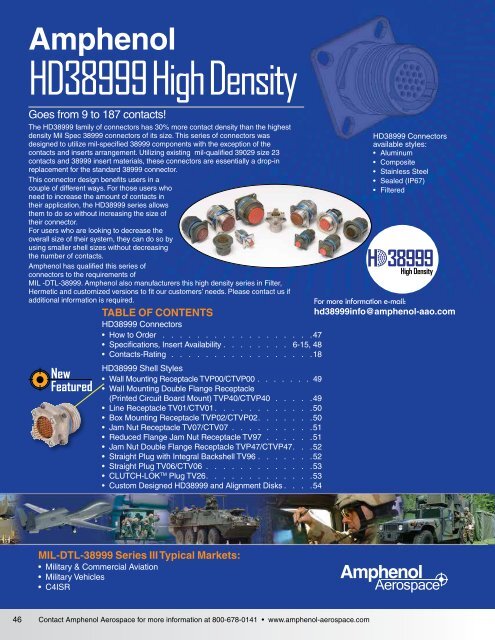
Goes II from 9 to 187 contacts!<br />
The I <strong>HD38999</strong> family of connectors has 30% more contact density than the highest<br />
SJT density Mil Spec 38999 connectors of its size. This series of connectors was<br />
designed to utilize mil-specified 38999 components with the exception of the<br />
Accessories<br />
contacts and inserts arrangement. Utilizing existing mil-qualified 39029 size 23<br />
Aquacon contacts and 38999 insert materials, these connectors are essentially a drop-in<br />
Herm/Seal replacement for the standard 38999 connector.<br />
PCB This connector design benefits users in a<br />
couple of different ways. For those users who<br />
need to increase the amount of contacts in<br />
<strong>High</strong> their application, the <strong>HD38999</strong> series allows<br />
Speed them to do so without increasing the size of<br />
Fiber their connector.<br />
Optics For users who are looking to decrease the<br />
overall size of their system, they can do so by<br />
Contacts using smaller shell sizes without decreasing<br />
<strong>Connectors</strong><br />
Cables<br />
the number of contacts.<br />
<strong>Amphenol</strong> has qualified this series of<br />
connectors to the requirements of<br />
MIL -DTL-38999. <strong>Amphenol</strong> also manufacturers this high density series in Filter,<br />
Hermetic and customized versions to fit our customers’ needs. Please contact us if<br />
additional information is required.<br />
New<br />
Featured<br />
TABLE OF CONTENTS<br />
<strong>HD38999</strong> <strong>Connectors</strong><br />
• How to Order . . . . . . . . . . . . . . . . . . 47<br />
• Specifications, Insert Availability. . . . . . . . 6-15, 48<br />
• Contacts-Rating. . . . . . . . . . . . . . . . . 18<br />
<strong>HD38999</strong> Shell Styles<br />
• Wall Mounting Receptacle TVP00/CTVP00. . . . . . . 49<br />
• Wall Mounting Double Flange Receptacle<br />
(Printed Circuit Board Mount) TVP40/CTVP40. . . . . 49<br />
• Line Receptacle TV01/CTV01. . . . . . . . . . . .50<br />
• Box Mounting Receptacle TVP02/CTVP02. . . . . . .50<br />
• Jam Nut Receptacle TV07/CTV07 . . . . . . . . . .51<br />
• Reduced Flange Jam Nut Receptacle TV97. . . . . . 51<br />
• Jam Nut Double Flange Receptacle TVP47/CTVP47. . .52<br />
• Straight Plug with Integral Backshell TV96. . . . . . .52<br />
• Straight Plug TV06/CTV06 . . . . . . . . . . . . .53<br />
• CLUTCH-LOK TM Plug TV26. . . . . . . . . . . . .53<br />
• Custom Designed <strong>HD38999</strong> and Alignment Disks . . . .54<br />
<strong>HD38999</strong> <strong>Connectors</strong><br />
available styles:<br />
• Aluminum<br />
• Composite<br />
• Stainless Steel<br />
• Sealed (IP67)<br />
• Filtered<br />
H 38999<br />
<strong>High</strong> <strong>Density</strong><br />
For more information e-mail:<br />
hd38999info@amphenol-aao.com<br />
Options<br />
Others<br />
Back-<br />
Shells<br />
MIL-DTL-38999 Series III Typical Markets:<br />
• Military & Commercial Aviation<br />
• Military Vehicles<br />
• C4ISR<br />
<strong>Amphenol</strong><br />
<strong>Aerospace</strong><br />
46 Contact <strong>Amphenol</strong> <strong>Aerospace</strong> for more information at 800-678-0141 • www.amphenol-aerospace.com
<strong>HD38999</strong> <strong>High</strong> <strong>Density</strong> <strong>Connectors</strong><br />
How to Order<br />
<strong>Amphenol</strong><br />
<strong>Aerospace</strong><br />
Easy Steps to build a part number... <strong>HD38999</strong><br />
P<br />
(prefix<br />
for<br />
Potted)<br />
TV<br />
TVP<br />
MTV<br />
CTV<br />
CTVP<br />
1. 2. 3. 4. 5. 6. 7.<br />
Connector Type<br />
TV or<br />
PTV (Potted version)<br />
Shell<br />
Styles<br />
Service<br />
Class<br />
Step 1. Select a Connector Type<br />
Step 2. Select a Shell Style<br />
Shell Size –<br />
Insert Arrangement<br />
Contact<br />
Type<br />
Alternate<br />
Positions<br />
PCB<br />
Options<br />
06 RW 23-151 P B (P25)<br />
Designates<br />
Tri-Start Series Connector<br />
Back panel mounted receptacle<br />
CLUTCH-LOK high vibration plug connector<br />
(Note: remove dashes in how to order part number<br />
when ordering CLUTCH-LOK)<br />
Tri-Start Composite Series connector<br />
Panel mounted composite receptacle<br />
Designates<br />
00 Wall mount receptacle<br />
40 Wall mount double flange receptacle<br />
01 Line receptacle<br />
02 Box mount receptacle - Consult <strong>Amphenol</strong> for availability<br />
06 Straight plug<br />
07 Jam nut receptacle<br />
47 Jam nut double flange receptacle<br />
26<br />
Proprietary CLUTCH-LOK high vibration<br />
straight plug (service Class RK)<br />
97<br />
Reduced flange jam nut receptacle<br />
(not available in composite)<br />
96<br />
Straight plug with integral backshell<br />
(not available in composite)<br />
Step 3. Select a Service Class<br />
RF<br />
RW<br />
RL<br />
RK<br />
DT<br />
DZ<br />
Designates<br />
Electroless nickel plated aluminum, optimum EMI<br />
shielding effectiveness -65dB @ 10GHz specification<br />
min., 48 hour salt spray, 175°C<br />
Corrosion resistant olive drab cadmium plate aluminum,<br />
500 hour extended salt spray, EMI -50dB @ 10GHz<br />
specification min.,175°C<br />
Corrosion resistant stainless steel, electro-deposited<br />
nickel, 48 hours salt spray, 175°C, non-firewall<br />
Corrosion resistant stainless steel, firewall capability,<br />
plus 500 hour salt spray resistance, EMI –45 dB @ 10<br />
GHz specification min., 175°C<br />
Durmalon plated, alternative to cadmium.<br />
Corrosion resistant, 500 hour extended salt spray<br />
EMI -50dB @ 10GHz specification min. without CR 6<br />
Zinc-Nickel alternative to cadmium.<br />
Corrosion resistant, 500 hour salt spray, conductive,<br />
–65°C to +175°C<br />
Step 4. Select a Shell Size – Insert Arrangement<br />
Shell Sizes are MIL-DTL-38999, Series III, with the newer <strong>High</strong><br />
<strong>Density</strong> insert arrangements chart on page 6-9 and illustrations on<br />
page 48.<br />
Shell Size Insert Arrangement<br />
9- 9<br />
11- 19<br />
13- 32<br />
15- 55<br />
17- 73<br />
19- 88<br />
21- 121<br />
23- 151<br />
25- 187<br />
Step 5. Select a<br />
Contact Type<br />
P<br />
S<br />
Designates<br />
Pin contacts<br />
Socket contacts<br />
EU<br />
EU<br />
EU<br />
<strong>Amphenol</strong><br />
/<br />
<strong>Amphenol</strong><br />
/<br />
RoHS<br />
2002<br />
/<br />
95<br />
/<br />
<strong>Amphenol</strong><br />
/<br />
RoHS<br />
2002<br />
RoHS<br />
2002<br />
/<br />
/<br />
95<br />
95<br />
/<br />
/<br />
EC<br />
EC<br />
EC<br />
Step 6. Select an Alternate Position<br />
A, B, C, D, E or blank for normal.<br />
Shell<br />
Size<br />
9<br />
11,<br />
13,<br />
and<br />
15<br />
17<br />
and<br />
19<br />
21,<br />
23,<br />
and<br />
25<br />
RECEPTACLE<br />
(front face shown)<br />
AR<br />
BSC˚<br />
BR<br />
BSC˚<br />
DR<br />
BSC˚<br />
Key & keyway<br />
arrangement<br />
identification letter<br />
CR<br />
BSC˚<br />
MAIN<br />
KEYWAY<br />
AR°<br />
or AP°<br />
BSC<br />
PLUG<br />
(front face shown)<br />
MAIN<br />
KEYWAY<br />
CP<br />
BSC<br />
AP<br />
BSC<br />
BP˚<br />
BSC<br />
DP<br />
BSC<br />
Step 7. Select a PCB Contact Option<br />
Pin<br />
Contacts<br />
˚<br />
BR° or<br />
BP° BSC<br />
˚<br />
˚<br />
CR° or<br />
CP° BSC<br />
DR° or<br />
DP° BSC<br />
N 105 140 215 265<br />
A 102 132 248 320<br />
B 80 118 230 312<br />
C 35 140 205 275<br />
D 64 155 234 304<br />
E 91 131 197 240<br />
N 95 141 208 236<br />
A 113 156 182 292<br />
B 90 145 195 252<br />
C 53 156 220 255<br />
D 119 146 176 298<br />
E 51 141 184 242<br />
N 80 142 196 293<br />
A 135 170 200 310<br />
B 49 169 200 244<br />
C 66 140 200 257<br />
D 62 145 180 280<br />
E 79 153 197 272<br />
N 80 142 196 293<br />
A 135 170 200 310<br />
B 49 169 200 244<br />
C 66 140 200 257<br />
D 62 145 180 280<br />
E 79 153 197 272<br />
Pin<br />
Contacts<br />
with Alignment<br />
Disc*<br />
Socket<br />
Contacts<br />
Socket<br />
Contacts<br />
with Alignment<br />
Disc**<br />
A plug with a given<br />
rotation letter will mate<br />
with a receptacle with<br />
the same rotation<br />
letter. The angles for<br />
a given connector are<br />
the same whether it<br />
contains pins or sockets.<br />
Inserts are not<br />
rotated in conjunction<br />
with the master key/<br />
keyway.<br />
PCB tail<br />
stickout<br />
+/-.040 inch<br />
P1* P1AD S1 S1AD .100” nominal<br />
P15* P15AD S15 S15AD .150” nominal<br />
P2 P2AD S2 S2AD .200” nominal<br />
P25* P25AD S25 S25AD .250” nominal<br />
P3* P3AD S3 S3AD .300” nominal<br />
P35 P35AD S35 S35AD .350” nominal<br />
* Not available in TV40 wall mount double flange receptacle or TV47<br />
jam nut double flange receptacle styles.<br />
** See page 54 for more information on alignment discs for <strong>HD38999</strong><br />
connectors.<br />
Note: Standard tail diameter is 0.019 ±.001<br />
Stick out is measured from the end of the connector shell to end of the contact<br />
38999<br />
III<br />
HD<br />
Dualok<br />
II<br />
I<br />
SJT<br />
Accessories<br />
Aquacon<br />
Herm/Seal<br />
PCB<br />
<strong>High</strong><br />
Speed<br />
Fiber<br />
Optics<br />
Contacts<br />
<strong>Connectors</strong><br />
Cables<br />
EMI Filter<br />
Transient<br />
26482<br />
Matrix 2<br />
83723 III<br />
Matrix|Pyle<br />
26500<br />
Pyle<br />
5015<br />
Crimp Rear<br />
Release<br />
Matrix<br />
22992<br />
Class L<br />
Back-<br />
Shells<br />
Options<br />
Others<br />
Contact <strong>Amphenol</strong> <strong>Aerospace</strong> for more information at 800-678-0141 • www.amphenol-aerospace.com<br />
47
38999<br />
III<br />
HD<br />
Dualok<br />
II<br />
I<br />
SJT<br />
Accessories<br />
Aquacon<br />
Herm/Seal<br />
PCB<br />
<strong>High</strong><br />
Speed<br />
Fiber<br />
Optics<br />
Contacts<br />
<strong>Connectors</strong><br />
Cables<br />
EMI Filter<br />
Transient<br />
26482<br />
Matrix 2<br />
83723 III<br />
Matrix|Pyle<br />
5015 26500<br />
Crimp Rear Pyle<br />
Release<br />
Matrix<br />
22992<br />
Class L<br />
<strong>Amphenol</strong><br />
<strong>Aerospace</strong><br />
Contacts & Tools<br />
Contact Part Numbers:<br />
Size 23 Sockets<br />
Size 23 Pins<br />
Sealing Plugs<br />
Crimp Barrel Dia.:<br />
(Inches) .034-.036<br />
Technical Data<br />
10-597330-735 (M39029/17-172)<br />
10-597331-735 (M39029/18-177)<br />
10-405996-222 (MS27488-22-2)<br />
Crimp Barrel Depth:<br />
(Inches) .151-.155<br />
<strong>HD38999</strong> series was designed to meet and/or exceed the specifications of<br />
MIL-DTL-38999. The connector series has been tested to all the requirements of<br />
38999 with the use of AS39029 size 23 contacts. Test reports are available upon<br />
request. The following is a summary of some of the performance requirements.<br />
EMI Shielding Effectiveness:<br />
Solid metal-to-metal coupling, EMI grounding fingers and conductive<br />
finishes have proven to be the ultimate in EMI/EMP shielding<br />
effectiveness. The charts on page 24 illustrated shielding effectiveness<br />
data which is typical in <strong>HD38999</strong> connectors as well as<br />
MIL-DTL-38999 connectors.<br />
Electrical:<br />
22 AWG: 5.0 AMPS<br />
24 AWG: 3.0 AMPS<br />
26 AWG: 2.0 AMPS<br />
28 AWG: 1.5 AMPS<br />
Insulation Resistance: 5000 megohms min.@500 VDC 25C<br />
Dielectric Withstanding Voltage: 1000 VRMS@sea level<br />
Environmental:<br />
Operating<br />
Temperature:<br />
Salt Spray:<br />
Metallized:<br />
Salt Spray<br />
Composite:<br />
8 1<br />
7<br />
2<br />
9<br />
6 3<br />
5 4<br />
–65°C to +175°C<br />
Electroless Nickel: 48 hours<br />
Anodic Coating, O. D. Cadmium, Durmalon,<br />
Zinc Nickel: 500 hours<br />
<strong>HD38999</strong> <strong>High</strong> <strong>Density</strong> <strong>Connectors</strong><br />
Contacts & Tools, Technical Data,<br />
Insert Availability<br />
Electroless Nickel: 1000 hours<br />
O. D. Cadmium, Durmalon, Zinc Nickel: 500 hours<br />
<strong>HD38999</strong> Insert Availability<br />
<strong>High</strong> <strong>Density</strong> Shell Sizes (Front of Pin Insert Shown)<br />
(all contacts are size 23)<br />
1 1<br />
12 2<br />
11 13<br />
18<br />
18 14 3<br />
29<br />
19<br />
10 17 15 4<br />
9<br />
32<br />
16<br />
8 5<br />
6<br />
7<br />
10<br />
17<br />
25<br />
32<br />
4 1<br />
40<br />
47<br />
53<br />
Tools:<br />
Crimp Tool: Daniels M22520/2-01<br />
Positioner: Daniels M22520/2-16 Socket<br />
Daniels M22520/2-13 Pin<br />
Insertion Tool: Daniels DAK225-22<br />
Removal Tool: Daniels DRK225-22<br />
Insertion/Removal Tool: M81969/16-04 (Plastic)<br />
Note: Wire insulation diameter greater than 0.045 is too large<br />
for the extraction tool to work properly. Connector damage is<br />
possible.<br />
H 38999<br />
<strong>High</strong> <strong>Density</strong><br />
Mechanical:<br />
Metallic Shells: Material: Aluminum Alloy, Stainless Steel<br />
Protection: Electroless Nickel, O.D. Cadmium,<br />
Durmalon (Nickel PTFE), Zinc Nickel<br />
Composite Shells: Material: Thermoplastic<br />
Protection: Electroless Nickel, O.D. Cadmium,<br />
Durmalon (Nickel PTFE), Zinc Nickel<br />
Contacts: Material: Copper Alloy<br />
Protection: Gold over Nickel<br />
Insert Retention<br />
to Shell:<br />
Durability:<br />
100 psi in axial load<br />
500 full mating and unmating cycles<br />
Vibration: 60G sine per MIL-DTL-38999L Para 4.5.23.2.1<br />
5G2 Random per EIA-364-28E, Test condition A<br />
1G2 Random per EIA-364-28E, Test condition I<br />
Shock:<br />
1 2<br />
3<br />
7<br />
8 15<br />
Per EIA-364-27B, 300g<br />
9-9 11-19 13-32 15-55 17-73 19-88<br />
3 6 19 18 18 22<br />
3 9<br />
16<br />
46<br />
52<br />
55<br />
24<br />
31<br />
39<br />
16<br />
25<br />
33<br />
42<br />
50<br />
59<br />
67<br />
72 73<br />
66<br />
71<br />
24<br />
32<br />
41<br />
49<br />
58<br />
1<br />
30<br />
31<br />
55<br />
73<br />
84<br />
88<br />
Back-<br />
Shells<br />
Options<br />
Others<br />
Increased number of contacts<br />
in <strong>HD38999</strong> insert pattern<br />
compared to Standard<br />
38999* contact density<br />
of same shell size.<br />
1 5<br />
6 13<br />
14<br />
22<br />
23<br />
32<br />
33 43<br />
44 55<br />
56 66<br />
67 78<br />
79 89<br />
90 99<br />
100 108<br />
109 116<br />
117 121<br />
1 4<br />
12<br />
5 11<br />
21<br />
22<br />
32<br />
33 44<br />
45 57<br />
58 69<br />
70 82<br />
83 94<br />
95<br />
108<br />
107<br />
119<br />
120<br />
131<br />
130<br />
140<br />
141<br />
147<br />
148<br />
151<br />
1<br />
3<br />
4 11<br />
12<br />
20<br />
21<br />
32<br />
33 45<br />
46 59<br />
60 72<br />
73 86<br />
87 101<br />
102<br />
115<br />
116<br />
128<br />
129<br />
142<br />
143<br />
155<br />
156<br />
167<br />
168<br />
176<br />
177<br />
184<br />
185 187<br />
21-121 23-151 25-187<br />
42 51 59<br />
48 Contact <strong>Amphenol</strong> <strong>Aerospace</strong> for more information at 800-678-0141 • www.amphenol-aerospace.com
<strong>HD38999</strong> <strong>High</strong> <strong>Density</strong> <strong>Connectors</strong><br />
TVP00/CTVP00<br />
Wall Mounting Receptacle<br />
TVP00(<br />
CTVP00(<br />
Shell<br />
Size<br />
MS<br />
Shell<br />
Size<br />
Code<br />
) - Crimp, Metal<br />
) - Crimp, Composite<br />
See how to build a part number on pages 47<br />
† Red band indicates fully mated<br />
B Thread<br />
Class 2A<br />
0.1P-0.3L-TS<br />
(Plated)<br />
L<br />
Max.<br />
(TV)<br />
L 1<br />
Max.<br />
(CTV)<br />
M<br />
+.000<br />
–.005<br />
(TV)<br />
S<br />
2 PLACES<br />
R 1<br />
2 PLACES<br />
R 2<br />
2 PLACES<br />
TT<br />
4 PLACES<br />
†† Blue band indicates rear release contact retention system.<br />
.005 M<br />
M 1<br />
+.000<br />
–.005<br />
(CTV) R 1 R 2 S<br />
Max.<br />
T<br />
4 PLACES<br />
T<br />
±.008<br />
Z.<br />
Max.<br />
(TV)<br />
Z 1<br />
Max.<br />
(CTV)<br />
A 1<br />
Back<br />
Panel<br />
Mount<br />
<strong>Amphenol</strong><br />
<strong>Aerospace</strong><br />
A 2<br />
Front<br />
Panel<br />
Mount<br />
AA Max.<br />
Panel<br />
Thickness<br />
9 A .6250 .469 .520 .820 .773 .719 .594 .948 .128 .153 .198 .650 .510 .234 .905 .908 .216<br />
11 B .7500 .469 .520 .820 .773 .812 .719 1.043 .128 .153 .198 .800 .620 .234 .905 .908 .194<br />
13 C .8750 .469 .520 .820 .773 .906 .812 1.137 .128 .153 .198 .910 .740 .234 .905 .908 .194<br />
15 D 1.0000 .469 .520 .820 .773 .969 .906 1.232 .128 .153 .198 1.040 .900 .234 .905 .908 .173<br />
17 E 1.1875 .469 .520 .820 .773 1.062 .969 1.323 .128 .153 .198 1.210 1.010 .234 .905 .908 .194<br />
19 F 1.2500 .469 .520 .820 .773 1.156 1.062 1.449 .128 .153 .198 1.280 1.130 .234 .905 .908 .194<br />
21 G 1.3750 .500 .552 .790 .741 1.250 1.156 1.575 .128 .183 .228 1.410 1.250 .204 .905 .904 .194<br />
23 H 1.5000 .500 .552 .790 .741 1.375 1.250 1.701 .154 .183 .228 1.530 1.360 .204 .905 .904 .242<br />
25 J 1.6250 .500 .552 .790 .741 1.500 1.375 1.823 .154 .183 .228 1.660 1.470 .204 .905 .904 .242<br />
All dimensions for reference only<br />
<strong>HD38999</strong> <strong>High</strong> <strong>Density</strong> <strong>Connectors</strong><br />
TVP40/CTVP40<br />
Wall Mounting Double<br />
Flange Receptacle<br />
(Printed Circuit Board Mount)<br />
TVP40(<br />
CTVP40(<br />
Shell<br />
Size<br />
) - Crimp, Metal<br />
) - Crimp, Composite<br />
See how to build a part number on pages 47<br />
* Contact stickout: see Step 7 of how to order on page 47.<br />
† Red band indicates fully mated<br />
MS Shell<br />
Size Code<br />
A<br />
Dia.<br />
±.005<br />
(TV)<br />
A<br />
Dia.<br />
±.005<br />
(CTV)<br />
B Thread<br />
Class 2A<br />
0.1P-0.3L-TS<br />
(Plated)<br />
M<br />
+.000<br />
–.005<br />
(TV)<br />
S<br />
2 PLACES<br />
R<br />
2 PLACES<br />
M 1<br />
±.003<br />
(CTV)<br />
R<br />
(Panel<br />
Mount)<br />
(CTV)<br />
B<br />
THREAD<br />
LL (TV)<br />
LL 1 (CTV)<br />
M (TV)<br />
M 1(CTV)<br />
AA<br />
RED<br />
BAND †<br />
BLUE<br />
BAND ††<br />
BLUE M (TV)<br />
BAND †† M 1 (CTV)<br />
RED<br />
BAND †<br />
B THREAD<br />
(4) CORROSION RESISTANT STEEL<br />
.112-40 UNC-3B SELF-LOCKING<br />
CLINCH NUTS PER MIL-N-45938/6-4C,<br />
R<br />
(Panel<br />
Mount<br />
(TV)<br />
Z (TV)<br />
Z 1(CTV)<br />
1.240 MAX<br />
M45938/6-6C EXCEPT SHELL SIZES 23 & 25<br />
TV40 .138-32 UNC-3B PER MIL-N-45938/7-2P,<br />
M45938/7-4P EXCEPT FOR SHELL SIZES 23 & 25<br />
S<br />
Max.<br />
(TV)<br />
L (TV)<br />
L 1 (CTV)<br />
–A–<br />
S<br />
Max.<br />
(CTV)<br />
V THREAD<br />
AA Max.<br />
Panel<br />
Thickness<br />
LL<br />
+.006<br />
–.000<br />
(TV)<br />
W<br />
2 PLACES<br />
(4) CORROSION RESISTANT STEEL<br />
.112-40 UNC-3B INSERTS<br />
.005 M<br />
PANEL HOLE<br />
DIMENSIONS<br />
BACK PANEL<br />
MOUNTING<br />
FRONT PANEL<br />
MOUNTING<br />
†† Blue band indicates rear release contact retention system. .005 M<br />
Inches<br />
LL1<br />
±.005<br />
(CTV)<br />
A 1<br />
A 2<br />
PCB Mounting<br />
Dimensions<br />
T Dia. (TV)<br />
TP<br />
Inches<br />
TT<br />
±.008<br />
W (CTV)<br />
TP<br />
9 A 1.016 1.016 .6250 .820 .770 .719 NA 1.094 .949 .234 .752 .532<br />
11 B 1.062 1.148 .7500 .820 .770 .812 .766 1.187 1.042 .234 .850 .601<br />
13 C 1.250 1.250 .8750 .820 .770 .906 .859 1.281 1.136 .234 .994 .703<br />
15 D 1.375 1.375 1.0000 .820 .770 .969 .938 1.344 1.230 .234 1.119 .791<br />
17 E 1.500 1.500 1.1875 .820 .770 1.062 1.016 1.437 1.323 .234 1.237 .875<br />
19 F 1.625 1.625 1.2500 .820 .770 1.156 1.110 1.531 1.449 .234 1.379 .975<br />
21 G 1.750 1.750 1.3750 .820 .738 1.250 1.206 1.625 1.573 .204 1.489 1.053<br />
23 H 1.875 1.875 1.5000 .820 .738 1.375 1.312 1.750 1.699 .204 1.619 1.195<br />
25 J 2.000 2.000 1.6250 .820 .738 1.500 1.438 1.875 1.823 .204 1.744 1.233<br />
All dimensions for reference only<br />
AA<br />
.673 ±.002<br />
CONTACT<br />
STICKOUT*<br />
.019 ±.001<br />
T<br />
A<br />
45°<br />
38999<br />
III<br />
HD<br />
Dualok<br />
II<br />
I<br />
SJT<br />
Accessories<br />
Aquacon<br />
Herm/Seal<br />
PCB<br />
<strong>High</strong><br />
Speed<br />
Fiber<br />
Optics<br />
Contacts<br />
<strong>Connectors</strong><br />
Cables<br />
EMI Filter<br />
Transient<br />
26482<br />
Matrix 2<br />
83723 III<br />
Matrix|Pyle<br />
26500<br />
Pyle<br />
5015<br />
Crimp Rear<br />
Release<br />
Matrix<br />
22992<br />
Class L<br />
Back-<br />
Shells<br />
Options<br />
Others<br />
Contact <strong>Amphenol</strong> <strong>Aerospace</strong> for more information at 800-678-0141 • www.amphenol-aerospace.com<br />
49
38999<br />
III<br />
HD<br />
Dualok TV01(<br />
II CTV01(<br />
I<br />
SJT<br />
Accessories<br />
Aquacon<br />
Herm/Seal<br />
PCB<br />
<strong>High</strong><br />
Speed<br />
Fiber<br />
Optics<br />
Contacts<br />
<strong>Connectors</strong><br />
Cables<br />
EMI Filter<br />
Transient<br />
26482<br />
Matrix 2<br />
83723 III<br />
Matrix|Pyle<br />
5015 26500<br />
Crimp Rear Pyle<br />
Release<br />
Matrix<br />
22992<br />
Class L<br />
Back-<br />
Shells<br />
Options<br />
Others<br />
<strong>Amphenol</strong><br />
<strong>Aerospace</strong><br />
Shell<br />
Size<br />
) - Crimp, Metal<br />
) - Crimp, Composite<br />
See how to build a part number on pages 47<br />
† Red band indicates fully mated<br />
†† Blue band indicates rear release contact retention system.<br />
MS Shell<br />
Size Code<br />
B Thread<br />
0.1P-0.3L-TS-2A<br />
(Plated)<br />
M<br />
+.000<br />
–.005<br />
(TV)<br />
M 1<br />
+.000<br />
–.005<br />
(CTV)<br />
50 Contact <strong>Amphenol</strong> <strong>Aerospace</strong> for more information at 800-678-0141 • www.amphenol-aerospace.com<br />
L<br />
Max.<br />
(TV)<br />
L 1<br />
Max.<br />
(CTV)<br />
S<br />
±.010<br />
(TV)<br />
S 1 ±.010<br />
(CTV)<br />
9 A .6250 .820 .773 .469 .520 .675 .635 .153 .198 .812 .699 .905 .908<br />
11 B .7500 .820 .773 .469 .520 .800 .765 .153 .198 .905 .875 .905 .908<br />
13 C .8750 .820 .773 .469 .520 .925 .885 .153 .198 1.093 1.007 .905 .908<br />
15 D 1.0000 .820 .773 .469 .520 1.050 1.100 .153 .198 1.219 1.140 .905 .908<br />
17 E 1.1875 .820 .773 .469 .520 1.238 1.197 .153 .198 1.375 1.229 .905 .908<br />
19 F 1.2500 .820 .773 .469 .520 1.300 1.260 .153 .198 1.469 1.380 .905 .908<br />
21 G 1.3750 .790 .741 .500 .552 1.425 1.385 .183 .228 1.625 1.493 .905 .904<br />
23 H 1.5000 .790 .741 .500 .552 1.550 1.510 .183 .228 1.750 1.626 .905 .904<br />
25 J 1.6250 .790 .741 .500 .552 1.675 1.635 .183 .228 1.875 1.777 .905 .904<br />
All dimensions for reference only<br />
See how to build a part number on pages 47<br />
† Red band indicates fully mated<br />
†† Blue band indicates rear release contact retention system.<br />
Shell<br />
Size<br />
MS<br />
Shell<br />
Size<br />
Code<br />
B Thread<br />
Class 2A<br />
0.1P-0.3L-<br />
TS (Plated)<br />
L<br />
Max.<br />
(TV)<br />
L 1<br />
Max.<br />
(CTV)<br />
M<br />
+.000<br />
–.005<br />
(TV)<br />
S<br />
2 PLACES<br />
R 1<br />
2 PLACES<br />
R 2<br />
2 PLACES<br />
TT<br />
4 PLACES<br />
GG (TV)<br />
GG 1(CTV)<br />
S (TV)<br />
S 1(CTV)<br />
2 PLACES<br />
<strong>HD38999</strong> <strong>High</strong> <strong>Density</strong> <strong>Connectors</strong><br />
TVP02/CTVP02<br />
Box Mounting Receptacle<br />
** See availablitly note below<br />
TVP02(<br />
CTVP02(<br />
) - Crimp, Metal<br />
) - Crimp, Composite<br />
.005 M<br />
**Consult <strong>Amphenol</strong> <strong>Aerospace</strong> for availability for box mount receptacles.<br />
<strong>HD38999</strong> <strong>High</strong> <strong>Density</strong> <strong>Connectors</strong><br />
TV01/CTV01<br />
Line Receptacle<br />
M 1<br />
+.000<br />
–.005<br />
(CTV) R 1 R 2 S<br />
Max.<br />
T<br />
±.008<br />
T<br />
4 PLACES<br />
Z.<br />
Max.<br />
(TV)<br />
B<br />
THREAD<br />
Z Max<br />
(TV)<br />
Z 1<br />
Max.<br />
(CTV)<br />
B<br />
THREAD<br />
Z 1 Max<br />
(CTV)<br />
BLUE<br />
BAND††<br />
RED<br />
BAND †<br />
A 1<br />
Back<br />
Panel<br />
Mount<br />
LL (TV)<br />
LL 1 (CTV)<br />
M (TV)<br />
M 1(CTV)<br />
GG<br />
±.010<br />
(TV)<br />
AA<br />
M (TV)<br />
M 1(CTV)<br />
LL (TV)<br />
LL 1 (CTV)<br />
A 2<br />
Front<br />
Panel<br />
Mount<br />
GG 1<br />
±.010<br />
(CTV)<br />
AA Max.<br />
Panel<br />
Thickness<br />
9 A .6250 .205 .250 .820 .773 .719 .594 .948 .128 .153 .198 .650 .510 .234 .905 .908 .216<br />
11 B .7500 .205 .250 .820 .773 .812 .719 1.043 .128 .153 .198 .800 .620 .234 .905 .908 .194<br />
13 C .8750 .205 .250 .820 .773 .906 .812 1.137 .128 .153 .198 .910 .740 .234 .905 .908 .194<br />
15 D 1.0000 .205 .250 .820 .773 .969 .906 1.232 .128 .153 .198 1.040 .900 .234 .905 .908 .173<br />
17 E 1.1875 .205 .250 .820 .773 1.062 .969 1.323 .128 .153 .198 1.210 1.010 .234 .905 .908 .194<br />
19 F 1.2500 .205 .250 .820 .773 1.156 1.062 1.449 .128 .153 .198 1.280 1.130 .234 .905 .908 .194<br />
21 G 1.3750 .235 .280 .790 .741 1.250 1.156 1.575 .128 .183 .228 1.410 1.250 .204 .905 .904 .194<br />
23 H 1.5000 .235 .280 .790 .741 1.375 1.250 1.701 .154 .183 .228 1.530 1.360 .204 .905 .904 .242<br />
25 J 1.6250 .235 .280 .790 .741 1.500 1.375 1.823 .154 .183 .228 1.660 1.470 .204 .905 .904 .242<br />
RED<br />
BAND †<br />
BLUE<br />
BAND ††<br />
Z (TV)<br />
Z 1(CTV)<br />
1.240 MAX<br />
–A–<br />
Z (TV)<br />
Z 1(CTV)<br />
.280 MIN FULL THD<br />
V THREAD<br />
L (TV)<br />
L 1 (CTV)<br />
L (TV)<br />
L 1(CTV)<br />
LL<br />
+.006<br />
–.000<br />
(TV)<br />
LL<br />
+.006<br />
–.000<br />
(TV)<br />
LL1<br />
±.005<br />
(CTV)<br />
Inches<br />
LL 1<br />
±.005<br />
(CTV)<br />
PANEL HOLE<br />
DIMENSIONS<br />
A 1<br />
BACK PANEL<br />
MOUNTING<br />
A 2<br />
FRONT PANEL<br />
MOUNTING<br />
Inches<br />
TT<br />
±.008<br />
All dimensions for reference only
<strong>HD38999</strong> <strong>High</strong> <strong>Density</strong> <strong>Connectors</strong><br />
TV07/CTV07<br />
Jam Nut Receptacle<br />
C<br />
TV07(<br />
CTV07(<br />
TV97(<br />
Shell<br />
Size<br />
) - Crimp, Metal<br />
) - Crimp, Composite<br />
See how to build a part number on pages 47<br />
† Red band indicates fully mated<br />
†† Blue band indicates rear release contact retention system.<br />
H .059 dia. min., 3 lockwire holes. Formed lockwire hole design (6 holes) is optional<br />
) - Crimp, Metal<br />
See how to build a part number on pages 47<br />
† Red band indicates fully mated<br />
†† Blue band indicates rear release contact retention system.<br />
MS Shell<br />
Size Code<br />
B Thread Class<br />
2A 0.1P-0.3L-TS<br />
(Plated)<br />
.043<br />
+.005<br />
–.000<br />
LOCK WIRE HOLES<br />
4 PLACES<br />
A<br />
+.010<br />
–.005<br />
.094<br />
±.005<br />
4 PLACES<br />
C Dia.<br />
Max.<br />
D 1<br />
+.010<br />
–.000<br />
B THREAD<br />
R THREAD<br />
D 2<br />
+.000<br />
–.010 M<br />
1.220 REF.<br />
M<br />
‘O’ RING<br />
RED<br />
BAND †<br />
R Thread<br />
(Plated)<br />
9-7543)<br />
9 A .6250 .104 .915 .693 .657 .871 M17X1-6g<br />
11 B .7500 .104 1.042 .825 .770 .871 M20X1-6g<br />
13 C .8750 .104 1.240 1.010 .955 .878 M25X1-6g<br />
15 D 1.0000 .104 1.357 1.135 1.085 .878 M28X1-6g<br />
17 E 1.1875 .104 1.630 1.260 1.210 .878 M32X1-6g<br />
19 F 1.2500 .135 1.816 1.385 1.335 .878 M35X1-6g<br />
21 G 1.3750 .135 1.942 1.510 1.460 .878 M38X1-6g<br />
23 H 1.5000 .135 2.067 1.635 1.585 .878 M41X1-6g<br />
25 J 1.6250 .135 2.190 1.760 1.710 .878 M44X1-6g<br />
All dimensions for reference only<br />
H<br />
S<br />
2 PLACES<br />
.125<br />
±.005<br />
A<br />
<strong>Amphenol</strong><br />
<strong>Aerospace</strong><br />
BLUE BAND †<br />
.062 –.125<br />
PANEL THICKNESS<br />
Inches<br />
JAM NUT<br />
D-HOLE<br />
MOUNTING<br />
Shell<br />
Size<br />
MS Shell<br />
Size Code<br />
B Thread Class<br />
2A 0.1P-0.3L-TS<br />
(Plated) C Max.<br />
D 1<br />
+.010<br />
–.000<br />
D 2<br />
+.000<br />
–.010<br />
H Hex<br />
+.017<br />
–.016<br />
S<br />
±.010<br />
V Thread<br />
Metric<br />
R Thread<br />
(Plated)<br />
9-7543<br />
9 A .6250 1.199 .693 .657 .875 1.062 M12X1-6g M17X1-6g<br />
11 B .7500 1.386 .825 .770 1.000 1.250 M15X1-6g M20X1-6g<br />
13 C .8750 1.511 1.010 .955 1.188 1.375 M18X1-6g M25X1-6g<br />
15 D 1.0000 1.636 1.135 1.085 1.312 1.500 M22X1-6g M28X1-6g<br />
17 E 1.1875 1.761 1.260 1.210 1.438 1.625 M25X1-6g M32X1-6g<br />
19 F 1.2500 1.949 1.385 1.335 1.562 1.812 M28X1-6g M35X1-6g<br />
21 G 1.3750 2.073 1.510 1.460 1.688 1.938 M31X1-6g M38X1-6g<br />
23 H 1.5000 2.199 1.635 1.585 1.812 2.062 M34X1-6g M41X1-6g<br />
25 J 1.6250 2.323 1.760 1.710 2.000 2.188 M37X1-6g M44X1-6g<br />
All dimensions for reference only<br />
<strong>HD38999</strong> <strong>High</strong> <strong>Density</strong> <strong>Connectors</strong><br />
TV97<br />
Reduced Flange<br />
C DIA.<br />
Jam Nut Receptacle<br />
B THREAD<br />
PANEL THICKNESS<br />
.062 MIN .125 MAX<br />
‘O’ RING<br />
RED<br />
BAND †<br />
.091 MAX<br />
K REF –A–<br />
SHELL SIZES 9/11 –<br />
.871<br />
SHELL SIZES 13/25 –<br />
.878<br />
1.280 MAX<br />
BLUE BAND ††<br />
.418 MAX<br />
V THREAD<br />
R THREAD<br />
Inches<br />
D 1 D 2<br />
JAM NUT<br />
D-HOLE<br />
MOUNTING<br />
D 1 D 2<br />
38999<br />
III<br />
HD<br />
Dualok<br />
II<br />
I<br />
SJT<br />
Accessories<br />
Aquacon<br />
Herm/Seal<br />
PCB<br />
<strong>High</strong><br />
Speed<br />
Fiber<br />
Optics<br />
Contacts<br />
<strong>Connectors</strong><br />
Cables<br />
EMI Filter<br />
Transient<br />
26482<br />
Matrix 2<br />
83723 III<br />
Matrix|Pyle<br />
26500<br />
Pyle<br />
5015<br />
Crimp Rear<br />
Release<br />
Matrix<br />
22992<br />
Class L<br />
Back-<br />
Shells<br />
Options<br />
Others<br />
Contact <strong>Amphenol</strong> <strong>Aerospace</strong> for more information at 800-678-0141 • www.amphenol-aerospace.com<br />
51
38999<br />
III<br />
HD<br />
Dualok<br />
II<br />
I<br />
SJT<br />
Accessories<br />
Aquacon<br />
Herm/Seal<br />
PCB<br />
<strong>High</strong><br />
Speed<br />
Fiber<br />
Optics<br />
Contacts<br />
<strong>Connectors</strong><br />
Cables<br />
EMI Filter<br />
Transient<br />
<strong>Amphenol</strong><br />
<strong>Aerospace</strong><br />
TV47(<br />
CTV47(<br />
) - Crimp, Metal<br />
) - Crimp, Composite<br />
C<br />
S<br />
H<br />
HEX<br />
B THREAD<br />
R THREAD<br />
.889 MAX.<br />
RED<br />
BAND †<br />
<strong>HD38999</strong> <strong>High</strong> <strong>Density</strong> <strong>Connectors</strong><br />
TV47/CTV47<br />
Jam Nut Double Flange Receptacle<br />
BLUE ††<br />
BAND<br />
.673 ±.002<br />
CONTACT<br />
STICKOUT*<br />
.062-.125<br />
PANEL THICKNESS<br />
(4) CORROSION RESISTANT STEEL<br />
.112-40 UNC-3B INSERTS<br />
.005 M<br />
.019 ±.001<br />
W<br />
2 PLACES<br />
V<br />
M<br />
45°<br />
D 1 D 2<br />
JAM NUT<br />
D-HOLE<br />
MOUNTING<br />
83723 III<br />
Matrix|Pyle<br />
5015 26500<br />
Crimp Rear Pyle<br />
Release<br />
Matrix<br />
22992<br />
Class L<br />
Back-<br />
Shells<br />
26482<br />
Matrix 2<br />
Options<br />
Others<br />
See how to build a part number on pages 47<br />
* Contact stickout dimension: see Step 7 of how to order on page 47.<br />
† Red band indicates fully mated<br />
†† Blue band indicates rear release contact retention system.<br />
H .059 dia. min., 3 lockwire holes. Formed lockwire hole design (6 holes) is optional<br />
Shell<br />
Size<br />
MS Shell<br />
Size Code<br />
B Thread Class<br />
2A 0.1P-0.3L-TS<br />
(Plated)<br />
C<br />
±.005<br />
(Jam Nut<br />
Flange Dia.<br />
D 1<br />
+.010<br />
–.000<br />
D 2<br />
+.000<br />
–.010<br />
H<br />
Hex<br />
+.017<br />
–.016<br />
M<br />
Dia.<br />
±.005<br />
R<br />
Thread<br />
Metric<br />
(Plated)<br />
S<br />
+.011<br />
–.010<br />
PCB Mounting<br />
Dimensions<br />
V Dia. (TV)<br />
TP<br />
W (CTV)<br />
TP<br />
9 A .6250 1.188 .700 .670 .875 1.016 M17X1-6g0.100R 1.062 .753 .532<br />
11 B .7500 1.375 .825 .770 1.000 1.148 M20X1-6g0.100R 1.250 .850 .601<br />
13 C .8750 1.500 1.010 .955 1.188 1.250 M25X1-6g0.100R 1.375 .994 .703<br />
15 D 1.0000 1.625 1.135 1.085 1.312 1.375 M28X1-6g0.100R 1.500 1.119 .791<br />
17 E 1.1875 1.750 1.260 1.210 1.438 1.500 M32X1-6g0.100R 1.625 1.237 .875<br />
19 F 1.2500 1.937 1.385 1.335 1.562 1.625 M35X1-6g0.100R 1.812 1.379 .975<br />
21 G 1.3750 2.062 1.510 1.460 1.688 1.750 M38X1-6g0.100R 1.937 1.489 1.053<br />
23 H 1.5000 2.188 1.635 1.585 1.812 1.875 M41X1-6g0.100R 2.062 1.644 1.145<br />
25 J 1.6250 2.312 1.760 1.710 2.000 2.000 M44X1-6g0.100R 2.188 1.744 1.233<br />
All dimensions for reference only<br />
Inches<br />
52 Contact <strong>Amphenol</strong> <strong>Aerospace</strong> for more information at 800-678-0141 • www.amphenol-aerospace.com
<strong>HD38999</strong> <strong>High</strong> <strong>Density</strong> <strong>Connectors</strong><br />
TV06/CTV06<br />
Straight Plug<br />
METAL<br />
TV06(<br />
CTV06(<br />
) - Crimp, Metal<br />
) - Crimp, Composite<br />
V THREAD<br />
.359 MAX<br />
COMPOSITE<br />
1.263 MAX<br />
1.220 MAX B THREAD<br />
.591 +.003<br />
–.000<br />
–A–<br />
BLUE BAND †<br />
Q<br />
<strong>Amphenol</strong><br />
<strong>Aerospace</strong><br />
38999<br />
III<br />
HD<br />
Dualok<br />
II<br />
I<br />
SJT<br />
Accessories<br />
Aquacon<br />
Herm/Seal<br />
PCB<br />
1.263 MAX<br />
B THREAD<br />
Q<br />
<strong>High</strong><br />
Speed<br />
Fiber<br />
Optics<br />
V THREAD<br />
BLUE BAND †<br />
Contacts<br />
<strong>Connectors</strong><br />
Cables<br />
.359 MAX<br />
.591 +.003<br />
–.000 –A–<br />
EMI Filter<br />
Transient<br />
<strong>HD38999</strong> <strong>High</strong> <strong>Density</strong> <strong>Connectors</strong><br />
TV96<br />
Straight Plug with Integral Backshell<br />
TV96(<br />
) (TV Type) - Crimp, Metal<br />
This MIL-DTL-38999 Series III style connector features an integral backshell<br />
design that eliminates the need for costly backshell accessories. The backshell<br />
feature is incorporated into the rear of the connector shell, allowing the user to<br />
attach the shield of their cable directly to the connector. This provides superior<br />
EMI shielding and ease for overmold applications. The straight plug with<br />
integral backshell is available in aluminum shells with OD Cad or Electroless<br />
Nickel plating.<br />
See how to build a part number<br />
on pages 47<br />
† Blue band indicates rear<br />
release contact retention<br />
system.<br />
Shell<br />
Size<br />
.500 ±.002<br />
+.001<br />
.376<br />
–.002<br />
C<br />
2 PLACES<br />
B<br />
2 PLACES<br />
.063<br />
+.001<br />
–.002<br />
.313 ±.002<br />
MS Shell<br />
Size Code<br />
BLUE BAND †<br />
1.600<br />
MAX.<br />
A<br />
Max.<br />
B<br />
+.005<br />
–.000<br />
A DIA.<br />
Inches<br />
C<br />
+.003<br />
–.002<br />
9 A .859 .416 .472<br />
11 B .969 .524 .580<br />
13 C 1.141 .652 .708<br />
15 D 1.266 .810 .866<br />
17 E 1.391 .928 .984<br />
19 F 1.500 1.046 1.102<br />
21 G 1.625 1.164 1.220<br />
23 H 1.750 1.282 1.338<br />
25 J 1.875 1.400 1.456<br />
26482<br />
Matrix 2<br />
83723 III<br />
Matrix|Pyle<br />
26500<br />
Pyle<br />
5015<br />
Crimp Rear<br />
Release<br />
Matrix<br />
22992<br />
Class L<br />
Back-<br />
Shells<br />
Options<br />
Others<br />
Contact <strong>Amphenol</strong> <strong>Aerospace</strong> for more information at 800-678-0141 • www.amphenol-aerospace.com<br />
53
<strong>Amphenol</strong><br />
<strong>Aerospace</strong><br />
Custom Designed <strong>HD38999</strong> <strong>Connectors</strong><br />
and Alignment Disks<br />
38999<br />
III<br />
HD<br />
Dualok<br />
II<br />
I<br />
SJT<br />
Accessories<br />
Aquacon<br />
Herm/Seal<br />
PCB<br />
<strong>High</strong><br />
Speed<br />
Fiber<br />
Optics<br />
Contacts<br />
<strong>Connectors</strong><br />
Cables<br />
EMI Filter<br />
Transient<br />
26482<br />
Matrix 2<br />
New Custom Designed <strong>HD38999</strong> <strong>Connectors</strong> -<br />
Provide More Interconnect Solutions:<br />
Alignment Disks<br />
Alignment disks keep contacts<br />
aligned for easier insertion into circuit<br />
boards. These are typically ordered<br />
with the connector - see step 7 of<br />
How to Order on page 47.<br />
D<br />
DIA.<br />
.032<br />
±.005<br />
Shell<br />
Size<br />
D Dia.<br />
±.010<br />
9 .234<br />
11 .350<br />
13 .500<br />
15 .725<br />
17 .750<br />
19 .850<br />
21 .953<br />
23 1.147<br />
25 1.250<br />
H 38999<br />
<strong>High</strong> <strong>Density</strong><br />
Filtered <strong>HD38999</strong><br />
<strong>Connectors</strong> - for EMI/EMP Protection<br />
<strong>High</strong> density patterns are available in filter 38999<br />
connectors - consult <strong>Amphenol</strong> <strong>Aerospace</strong> for<br />
ordering.<br />
83723 III<br />
Matrix|Pyle<br />
5015 26500<br />
Crimp Rear Pyle<br />
Release<br />
Matrix<br />
<strong>HD38999</strong> for Gigabit Ethernet Applications<br />
The <strong>HD38999</strong> is available for high speed (Gigabit Ethernet) data transmission<br />
in the size 9-9 insert pattern.<br />
Data transmission performance of this connector insert:<br />
• 10 Base T, 100 Base TX, and 1000 Base T networks using Cat 5e per TIA/<br />
EIA568B and Class D per ISO/IEC 11801.<br />
(Test report available - consult <strong>Amphenol</strong> <strong>Aerospace</strong> for more information)<br />
Signal-Ground Pin Configuration<br />
Wiring Recommendations<br />
22992<br />
Class L<br />
Back-<br />
Shells<br />
Options<br />
Others<br />
White/Orange<br />
Orange<br />
Brown<br />
1 8<br />
2<br />
9<br />
3 7<br />
5 6<br />
4<br />
Blue<br />
View Rear of Connector<br />
White/Blue<br />
White/Green<br />
Ground/or<br />
cavity not used<br />
Green<br />
White/Brown<br />
<strong>HD38999</strong> Connector with 9-9<br />
Insert Pattern (Rear View)<br />
54 Contact <strong>Amphenol</strong> <strong>Aerospace</strong> for more information at 800-678-0141 • www.amphenol-aerospace.com


