081509 - Conductix-Wampfler
081509 - Conductix-Wampfler
081509 - Conductix-Wampfler

Create successful ePaper yourself
Turn your PDF publications into a flip-book with our unique Google optimized e-Paper software.
KAT0815-0001c-E<br />
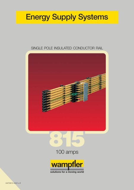
Energy Supply Systems<br />
SINGLE POLE INSULATED CONDUCTOR RAIL<br />
815<br />
100 amps
Conductor rail system in a high bay storage<br />
Slip ring with conductor rail system in<br />
a stretch-foil packing machine<br />
Electric overhead monorail with conductor rail - trolley on<br />
the way to the high bay storage
Table of contents<br />
Basic information<br />
Description ...................................................................................................<br />
Technical data ..............................................................................................<br />
Conductor rails and accessories<br />
Conductor rails ............................................................................................. 4<br />
Rail connectors ............................................................................................. 4<br />
Anchor cap ................................................................................................... 5<br />
Power feeds ................................................................................................. 5<br />
Hanger clamps ............................................................................................. 6<br />
End caps for transfer points / End caps ........................................................ 9<br />
Air gap separating points .............................................................................. 9<br />
End cap sets - complete ............................................................................... 10<br />
Expansion joints ............................................................................................ 12<br />
Current collectors and accessories<br />
Current collectors ......................................................................................... 16<br />
Support plates for current collectors ............................................................ 21<br />
Connection cables ........................................................................................ 22<br />
Collector shoe control units .......................................................................... 23<br />
Spare parts ................................................................................................... 24<br />
Accessories .................................................................................................. 25<br />
Others<br />
Tools............................................................................................................. 26<br />
Curves .......................................................................................................... 27<br />
System arrangement ..................................................................................... 28<br />
Questionnaire................................................................................................ 29<br />
System review .............................................................................................. 30<br />
Programme overview .................................................................................... 32<br />
General hints................................................................................................. 32<br />
- 1 -<br />
2<br />
3
Description<br />
<strong>Wampfler</strong> “single pole insulated conductor rail” programme 815<br />
The <strong>Wampfler</strong> insulated conductor rail programme 815 is protected against direct contact and used for indoor installations in<br />
overhead mono rails and slip rings. With the rail spacing of 12 mm or 14 mm it is possible to install 12 poles max. on overhead<br />
mono rail size 180 and 16 poles max. on size 240. Simple and quick installation was a main design principle.<br />
100 Amps<br />
protected against direct contact<br />
little space consumption<br />
CONDUCTOR RAILS<br />
The conductor rails are available in copper (max. nominal current<br />
100 Amps) and steel (max. nominal current 32 Amps) and<br />
have a plastic cover insulation. The standard lengths are 4000<br />
and 6000 mm; intermediate lengths are available. The earth<br />
conductor insulation cover is marked with a green stripe on both<br />
sides over the total length.<br />
CURVES<br />
Horizontal and vertical curves can be bent in the factory or on<br />
site.<br />
SUPPORT<br />
The conductor rail sections are fitted into the hanger clamps<br />
which are constructed as a sliding support. The support spacing<br />
is max. 500 mm for straight installations and 400 mm for<br />
curved systems.<br />
Depending on the type of plastic hanger clamps they can be<br />
screwed or clipped to special runway profiles.<br />
An adaption to specific customer profiles is easy to manufacture.<br />
RAIL CONNECTION<br />
The single rail sections are connected by a plug-in or a screw<br />
connection. Access to the connectors is easy from the frontside<br />
of the conductor rail. Every rail joint is protected against<br />
contact by an insulation cover.<br />
POWER FEED<br />
The power feed is made by a power feed connector or a power<br />
feed end cap. The power feed connector can be installed instead<br />
of the rail connector at any point of the conductor rail<br />
system. The connection is made by crimp terminals with a cross<br />
section of 1,5 up to 10 mm². Furthermore it is possible to feed<br />
in at the end cap for transfer points or separating points. The<br />
connection is made by crimp terminals with a cross section of<br />
1,5 up to 6 mm². The crimp terminals are include in the delivery.<br />
END CAPS / END CAPS FOR TRANSFER POINTS<br />
Long end caps for transfer points are used at switches to enable<br />
an easy and smooth traversing. These end caps accommodate<br />
a lateral misalignment of ± 3 mm in all directions.<br />
END CAPS FOR SEPARATING POINTS<br />
and EXPANSION JOINTS<br />
Short end caps can be used to produce air gap separating points<br />
or expansion joints. The expansion joints can accomodate an<br />
expansion of 8 - 40 mm during temperature change.<br />
- 2 -<br />
installation vertical and horizontal<br />
simple and quick installation<br />
CURRENT COLLECTORS<br />
The compact current collector unit is made of a few parts. Separate<br />
fully insulated collector arms are able to move in all directions.<br />
Current collectors are easily exchangeable due to the<br />
snap-in technique. The earth collector is marked green and is<br />
mounted in a leading or lagging position. The collector shoes<br />
can be checked without demounting and can easily be replaced.<br />
The current collectors can accomodate lateral and vertical misalignments<br />
of ±10 mm. They transmit a continuous current of<br />
max. 50 Amps. Single-head or double-head current collectors<br />
mounted on one collector arm are available. 6-, 8- and 10-pole<br />
type current collector units are in production. Please contact us<br />
for other number of poles.<br />
The collector shoes are made from copper graphite or for long<br />
duration applications they are made from pure graphite.<br />
COLLECTOR SHOE CONTROL UNIT<br />
The wearing of the collector shoes will be checked every time<br />
the current collectors passes the unit.<br />
INSTALLATION<br />
For detailed informationen please refer our installation instruction<br />
(MV0815-0001E).<br />
PROTECTION AGAINST DIRECT CONTACT<br />
See hint on page 3!<br />
Remark:<br />
Should the rail connector, power feed, air gap separating point<br />
or expansion joint not rest on the track section, hanger clamps<br />
are to be positioned on both sides at max. spacing of 200 mm.
Technical data<br />
<strong>Wampfler</strong> “single pole insulated conductor rail“ programme 815<br />
Conductor rail Copper<br />
Type 081516<br />
Nominal current at 100% duty cycle and 35°C [A] 100<br />
Cross section of conductor [mm 2] 25<br />
Resistance at 35°C [Ω/m] 0.000745<br />
Impedance at 12 mm rail spacing [Ω/m] 0.000747<br />
Impedance at 14 mm rail spacing [Ω/m] 0.000748<br />
Nominal voltage [V] 500<br />
Support spacing max. [mm] 500 in straight applications; 400/250 in horizontal/vertical curves<br />
Rail length [mm] Standard 4000 and 6000; intermediate lengths are available<br />
External dimensions [mm] 9.6 x 15.2<br />
Ambient temperature max. 55°C<br />
Ambient temperature min. -30°C<br />
Protection against direct contact to VDE 0470 part 1 / EN 60 529 / IEC 529<br />
and DIN 57 100 part 410 5.2.1 / 5.3 / VDE 0100 part 410<br />
and DIN / VDE 0100 Teil 726 4 and EN 60 204 part 1<br />
Protection type IP 23<br />
Dielectric strength to VDE 0303 part 21 / IEC 243 22.4 kV/mm<br />
Surface resistance to DIN IEC 112 VDE 0303 T1 600 < CTI<br />
Combustibility of insulation cover to UL 94 V - 0<br />
Air and surface creepage depending on degree of pollution; surface creepage distance 30 mm<br />
to DIN VDE 0110 part 1 + 2<br />
Chemical resistance of the profile at<br />
an ambient temperature of +45°C Benzine resistant Sodium hydroxide 25% resistant<br />
Mineral oil resistant Hydrochlorid acid resistant<br />
Grease resistant Sulphuric acid up to 50% resistant<br />
Note: Additional informations on request.<br />
The materials of the conductor rail systems are weather resistant and have<br />
got a high resistance against certain chemicals. For special applications<br />
please contact us. Please be careful with solvents and contact sprays.<br />
- 3 -<br />
PE (green stripe)
081516-...<br />
Conductor rails, Rail connectors<br />
Insulated conductor rails<br />
Type Material Order-Number Length Weight<br />
Phase (PH) Earth (PE) [m] [kg]<br />
Conductor rail Rail: Copper<br />
100 Amps Insulation: PVC<br />
Conductor rail Rail: Copper<br />
100 Amps Insulation: PVC<br />
Rail connectors<br />
081521 081526-...<br />
Rail connector<br />
conductor rail<br />
Please note also the mounting instruction MV0815-0001E!<br />
- 4 -<br />
insulation cover<br />
081516-4x11 081516-4x12 4 1.092<br />
081516-6x11 081516-6x12 6 1.638<br />
Rail connector 081526-...:<br />
- to be used in straight applications only.<br />
- if a connection with a plug-in connector<br />
is opened, the connector has to be replaced<br />
by a new one!<br />
Type Order- For max. current Weight<br />
Number [Amps] [kg]<br />
Screw type 081521 100 0.016<br />
Plug-in type 081526-6 67 0.010
081531<br />
Anchor cap, Power feeds<br />
Anchor cap<br />
The anchor caps are mounted on both sides of a hanger clamp.<br />
The hanger clamp must be bolted to the overhead runway beam!<br />
081551-...<br />
overhead runway beam<br />
engagement pin anchor cap hanger clamp<br />
Type Order-Number Weight<br />
[kg]<br />
Anchor cap 081531 0.002<br />
Power feeds<br />
Type Order-Number Cross section Weight<br />
[mm2] [kg]<br />
081551-1 1.5 - 2.5 0.016<br />
Power feed 081551-2 4 - 6 0.016<br />
081551-3 5 - 10 0.016<br />
- 5 -<br />
screw<br />
anchor cap<br />
10 mm²<br />
(max. cable diameter
Hanger clamps<br />
Standard application screw type<br />
Support spacing max. for straight installations for horizontal curves for vertical curves<br />
[mm] 500 400 250<br />
Each following drawing shows a standard application.<br />
Special hanger clamps designed for easy fixing onto mono rail profiles on request.<br />
Please ask for a list of available special hanger clamps.<br />
081543-... / 08-S280-...<br />
Shown is a 8-pole hanger clamp.<br />
Type Order-Number Poles Weight<br />
[kg]<br />
08-S280-0198 4 0.009<br />
Hanger clamp<br />
08-S280-0229<br />
08-S280-0305<br />
5<br />
6<br />
0.011<br />
0.013<br />
081543-08x14 8 0.025<br />
- 6 -<br />
14 mm rail spacing
081543-...<br />
Shown is a 10-pole hanger clamp.<br />
Hanger clamps<br />
Standard application screw type<br />
Type Order-Number Poles Weight<br />
[kg]<br />
Hanger clamp 081543-10x12 10 0.036<br />
See following a list of press-in hanger clamps (for overhead runway beams).<br />
- 7 -<br />
12 mm rail spacing
Hanger clamps<br />
Application examples<br />
8-poles 10-poles 8-poles 10-poles 8-poles<br />
10-poles 8-poles 10-poles 8-poles 10-poles<br />
10-poles 8-poles 10-poles 8-poles<br />
- 8 -
End caps for transfer points/End caps, Air gap separating points<br />
081574-... / 081576-... / 081577-...<br />
25<br />
40<br />
081574-... (End cap for transf. points)<br />
- also used as end cap<br />
- max. horizontal and vertical<br />
deflections: ± 3 mm<br />
081594-...<br />
max. 6 mm 2<br />
25,5<br />
End caps for transfer points/End caps “long” and “short”<br />
36<br />
30,5<br />
45,5<br />
081576-... (End cap for transf. points)<br />
- max. horizontal deflection: ± 3 mm<br />
- max. vertical deflection: ± 5 mm<br />
Air gap separating points<br />
76<br />
80<br />
- 9 -<br />
3,5-4,5<br />
21<br />
21<br />
36<br />
081577-... (End cap)<br />
- is used for air gap separating points<br />
Type Order-Number Cross section Weight<br />
[mm 2] [kg]<br />
End cap for transfer<br />
points/end cap “long“<br />
for 12 mm pole distance<br />
End cap for transfer<br />
points/end cap “long“<br />
for 14 mm pole distance<br />
End cap for .../end cap<br />
“long“ for 14 mm pole distance<br />
and vertical deflection ±5 mm<br />
End cap<br />
“short“ for<br />
12 and 14 mm pole distance<br />
max. 6 mm 2<br />
081574-01x12x0 without power feed 0.016<br />
081574-01x12x2 1.5 - 2.5 0.018<br />
081574-01x12x6 4 - 6 0.018<br />
081574-01x14x0 without power feed 0.016<br />
081574-01x14x2 1.5 - 2.5 0.018<br />
081574-01x14x6 4 - 6 0.018<br />
081576-01x14x0 without power feed 0.016<br />
081576-01x14x2 1.5 - 2.5 0.018<br />
081576-01x14x6 4 - 6 0.018<br />
081577-01x12x0 without power feed 0.016<br />
081577-01x12x2 1.5 - 2.5 0.018<br />
081577-01x12x6 4 - 6 0.018<br />
without expansion<br />
max. 6 mm 2<br />
max. 6 mm 2<br />
Type Order-Number Cross section Weight<br />
[mm2 ] [kg]<br />
without power feed 081594-1 - 0.035<br />
Air gap separating point<br />
with power feed<br />
081594-2<br />
081594-3<br />
1.5 - 2.5<br />
4 - 6<br />
0.041<br />
0.041
End cap set<br />
complete<br />
6-pole 2)<br />
End cap set<br />
complete<br />
8-pole 2)<br />
End cap sets - complete<br />
for transfers (switches, lifters, etc.) / 6- and 8-poles / with and without power feed<br />
081571-... / 081573-...<br />
Shown is the 8-pole “end cap set - complete” without power feed.<br />
8-pole “end cap set - complete” = end cap set + 8 pc. end caps for transfer points / end cap “long”.<br />
This end cap set is screwed onto the overhead runway beam section.<br />
The end caps of the individual conductor rail poles are clipped into it.<br />
081573-... can only be used in connection with double current collectors. As an alternative to double current collectors you<br />
can use 2 single current collectors arranged one after the other, with a restricted vertical deflection of ± 4 mm.<br />
Type Order-Number Poles A B C D E F G Weight Cross section<br />
[mm] [mm] [mm] [mm] [mm] [mm] [mm] [kg] [mm 2]<br />
End cap set<br />
complete<br />
6-pole<br />
End cap set<br />
complete<br />
8-pole<br />
081571-06x14x0 0.140 1)<br />
081571-06x14x2 6 14 114 22 70 61 35 49 0.142 1.5 - 2.5<br />
081571-06x14x6 0.145 4 - 6<br />
081571-08x14x0 0.172 1)<br />
081571-08x14x2 8 14 114 22 70 61 35 49 0.182 1.5 - 2.5<br />
081571-08x14x6 0.185 4 - 6<br />
081573-06x14x0 0.140 1)<br />
081573-06x14x2 6 14 114 22 70 66,5 35 54,5 0.142 1.5 - 2.5<br />
081573-06x14x6 0.145 4 - 6<br />
081573-08x14x0 0.172 1)<br />
081573-08x14x2 8 14 114 22 70 66,5 35 54,5 0.182 1.5 - 2.5<br />
081573-08x14x6 0.185 4 - 6<br />
1) = without power feed 2) = lateral deflection ± 5 mm<br />
- 10 -<br />
end cap for transfer points / end cap “long“<br />
8-pole end cap set<br />
08-E012-0075
081571-...<br />
End cap sets - complete<br />
for transfers (switches, lifters, etc.) / 10-poles / with and without power feed<br />
Shown is the 10-pole “end cap set - complete” without power feed.<br />
10-pole “end cap set - complete” = end cap set + 10 pc. end caps for transfer points / end cap “long”.<br />
This end cap set is screwed onto the overhead runway beam section.<br />
The end caps of the individual conductor rail poles are clipped into it.<br />
Type Order-Number Poles A B C D E F G Weight Cross section<br />
[mm] [mm] [mm] [mm] [mm] [mm] [mm] [kg] [mm 2]<br />
End cap<br />
set - complete<br />
1) = without power feed<br />
end cap for transfer points / end cap “long“<br />
10-pole end cap set<br />
08-E012-0151<br />
081571-06x12x0 6 12 74.5 8.7 47.6 74 34.5 48.5 0.140 1)<br />
081571-10x12x0 0.211 1)<br />
081571-10x12x2 10 12 120 30.1 71.4 74 34.5 48.5 0.218 1.5 - 2.5<br />
081571-10x12x6 0.223 4 - 6<br />
- 11 -
081561-...<br />
Expansion joints<br />
with 8 mm expansion<br />
Type Order-Number Expansion range Cross section Number of Weight<br />
[mm] [mm 2] expansion gaps [kg]<br />
Expansion joint 081561-311 8 2 x 2.5 1 0.050<br />
Shown is the 10-poles expansion joint.<br />
Type Order-Number Expansion range Cross section Poles Number of<br />
[mm] [mm 2] expansion gaps<br />
081561-381 8 2 x 2.5 8 1<br />
Expansion joint 081561-391 8 2 x 2.5 9 1<br />
081561-301 8 2 x 2.5 10 1<br />
- 12 -<br />
hanger clamp<br />
Expansion joints delivered<br />
with bridge cables in different lengths.
Expansion joints<br />
with 8 mm expansion / number of expansion joints / air gap adjustment<br />
Calculation of the number of expansion joints<br />
∆t in °C<br />
Air gap adjustment of the expansion joints<br />
Ambient temperature [ºC] during installation<br />
expansion joint 8 mm anchor cap<br />
L = Length* �t �t �t �t �t �t<br />
[m] 10 20 30 40 50 60<br />
10 - - 1 1 2 2<br />
20 - 1 2 2 3 3<br />
30 1 2 2 3 4 4<br />
40 1 2 3 4 5 6<br />
50 2 3 4 5 6 7<br />
60 2 3 4 6 7 8<br />
* = track length between end cap sets, curves (with 90° ... 180° curves and R ≤ 1000 mm the curves act as anchor points)<br />
or other components of the installation, which act as anchor points.<br />
∆t = ∆t a + ∆t rail ∆t a = temperature range of the ambient temperature<br />
∆t rail = temperature rise of the conductor rail<br />
for 40% duty cycle ∆t rail = 10°C<br />
for 65% duty cycle ∆t rail = 20°C<br />
for 100% duty cycle ∆t rail = 30°C<br />
air gap [mm]<br />
- 13 -<br />
curve<br />
Instruction:<br />
tmin = lowest temperature that occurs in the respective<br />
area of application<br />
tmax = highest operational temperature that occurs<br />
in the respective area of application<br />
1. Draw a connecting line from tmin to tmax 2. Mark the ambient temperature during operation<br />
horizontally<br />
3. Draw a line from the intersection vertically down<br />
and read the air gap to be set<br />
Examples:<br />
� = Temperature range from 0°C to +60°C.<br />
Ambient temp. during installation: + 20°C<br />
Air gap: ca. 5 mm<br />
� = Temperature range from +10°C bis +30°C.<br />
Ambient temp. during installation: + 25°C<br />
Air gap: ca. 2 mm
081562-...<br />
xX<br />
Expansion joints<br />
with 20 mm or 40 mm expansion<br />
use with double current collector 081508-... / <strong>081509</strong>-... only<br />
hanger clamp<br />
- 14 -<br />
Expansion joints delivered<br />
with bridge cables in different lengths.<br />
Type Order-Number Expansion range Cross section Number of Weight<br />
[mm] [mm2] expansion gaps [kg]<br />
Expansion joint 081562-311 20 2 x 2.5 1 0.052<br />
X = 10 - 30 mm<br />
Shown is the 10-poles expansion joint with 20 mm expansion range.<br />
The expansion joint with 40 mm expansion range<br />
consists of 2 sets of 20 mm expansion joints!<br />
Type Order-Number Expansion range Cross section Poles Number of<br />
[mm] [mm2 ] expansion gaps<br />
081562-361 20 2 x 2.5 6 1<br />
081562-381 20 2 x 2.5 8 1<br />
081562-391 20 2 x 2.5 9 1<br />
Expansion joint<br />
081562-301<br />
081562-362<br />
20<br />
40<br />
2 x 2.5<br />
2 x 2.5<br />
10<br />
6<br />
1<br />
2<br />
081562-382 40 2 x 2.5 8 2<br />
081562-392 40 2 x 2.5 9 2<br />
081562-302 40 2 x 2.5 10 2<br />
X
Expansion joints<br />
with 20 mm or 40 mm expansion / number of expansion joints / air gap adjustment<br />
Calculation of the number of expansion joints<br />
∆t in °C<br />
Air gap adjustment of the expansion joints<br />
Ambient temperature [ºC] during installation<br />
expansion joint 20 mm anchor cap<br />
L = Length* �t �t �t �t �t �t<br />
[m] 10 20 30 40 50 60<br />
10 - - 1 1 1 1<br />
20 - 1 1 1 1 1<br />
30 1 1 1 1 2 2<br />
40 1 1 1 2 2 3<br />
50 1 1 2 2 3 3<br />
60 1 1 2 3 3 4<br />
* = track length between end cap sets, curves (with 90° ... 180° curves and R ≤ 1000 mm the curves act as anchor points)<br />
or other components of the installation, which act as anchor points.<br />
∆t = ∆t a + ∆t rail ∆t a = temperature range of the ambient temperature<br />
∆t rail = temperature rise of the conductor rail<br />
for 40% duty cycle ∆t rail = 10°C<br />
for 65% duty cycle ∆t rail = 20°C<br />
for 100% duty cycle ∆t rail = 30°C<br />
air gap [mm]<br />
- 15 -<br />
curve<br />
Instruction:<br />
tmin = lowest temperature that occurs in the respective<br />
area of application<br />
tmax = highest operational temperature that occurs<br />
in the respective area of application<br />
1. Draw a connecting line from tmin to tmax 2. Mark the ambient temperature during operation<br />
horizontally<br />
3. Draw a line from the intersection vertically down<br />
and read the air gap to be set<br />
Examples:<br />
� = Temperature range from 0°C to +60°C.<br />
Ambient temp. during installation: + 20°C<br />
Air gap: ca. 13 mm<br />
� = Temperature range from +10°C bis +30°C.<br />
Ambient temp. during installation: + 25°C<br />
Air gap: ca. 5 mm
Current collectors<br />
Installation hints<br />
It must be ensured that the current collector central axis is mounted exactly onto the centre axis of the conductor rail and the<br />
specified installation distance between the arm axis and the sliding surface is strictly observed.<br />
The connection cables must be highly flexible in order to guarantee complete freedom of functioning of the current collectors and<br />
they must be secured with a cable binder so that no tensile or torsional forces are transmitted onto the current collector head.<br />
The table below indicates the colours of the current collector components for 8 and 10 pole current collectors, phase (PH) as well<br />
as protection earth (PE).<br />
Poles Rail spacing Phase (PH) Earth (PE)<br />
[mm] Current collector arm Collector shoe insul. Current collector arm Collector shoe insul.<br />
8 14 Yellow Black Green Green<br />
10 12 Yellow Grey Green Turquoise<br />
081506-...<br />
Current collector units type 16 Amps with 63 mm shoe length<br />
support plate<br />
Collector shoe material: pure graphite<br />
It must be guaranteed that the connection<br />
cables cannot exert any tension, pressure<br />
or torsion on the current collectors!<br />
Visual difference of the current collector<br />
parts: see above table!<br />
Current collectors (single pole) and support plates: see pages 20 and 21!<br />
- 16 -<br />
with terrminal lug connection<br />
Movement horizontal: ±10 mm<br />
vertical: ±10 mm<br />
Contact pressure: 6 N<br />
Type A B L Amps Poles Order-Number Weight<br />
[mm] [mm] [mm] [kg]<br />
Current collector unit<br />
with PE<br />
Current collector unit<br />
without PE<br />
sliding surface<br />
max. wearing height<br />
connection cable to be ordered separately<br />
14 6 54 16 4 081506-0443 0.195<br />
14 6 82 16 6 081506-0643 0.275<br />
14 20 110 16 8 081506-0843 0.370<br />
12 25 120 16 10 081506-1023 0.445<br />
14 6 54 16 4 081506-0441 0.195
081507-...<br />
Current collectors<br />
Current collector units type 35 Amps with 63 mm shoe length<br />
support plate<br />
Collector shoe material: copper graphite<br />
It must be guaranteed that the connection<br />
cables cannot exert any tension, pressure<br />
or torsion on the current collectors!<br />
Visual difference of the current collector<br />
parts: see page 16!<br />
Current collectors (single pole) and support plates: see page 21!<br />
- 17 -<br />
with terminal lug connection<br />
Movement horizontal: ±10 mm<br />
vertical: ±10 mm<br />
Contact pressure: 6 N<br />
Type A B L Amps Poles Order-Number Weight<br />
[mm] [mm] [mm] [kg]<br />
Current collector unit<br />
with PE<br />
Current collector unit<br />
without PE<br />
sliding surface<br />
max. wearing height<br />
connection cable to be ordered separately<br />
14 6 54 35 4 081507-0443 0.220<br />
14 6 82 35 6 081507-0643 0.310<br />
14 20 110 35 8 081507-0843 0.420<br />
12 25 120 35 10 081507-1023 0.505<br />
14 6 54 35 4 081507-0441 0.220
081508-...<br />
Current collectors<br />
Double current collector units type 35 Amps with 2 x 50 mm shoe length<br />
support plate<br />
Collector shoe material: pure graphite<br />
It must be guaranteed that the connection<br />
cables cannot exert any tension, pressure<br />
or torsion on the current collectors!<br />
Visual difference of the current collector<br />
parts: see page 16!<br />
Type A B L Amps Poles Order-Number Weight<br />
[mm] [mm] [mm] Trailing-Mode Reversing-Mode [kg]<br />
Double current collector unit<br />
with PE<br />
Double current collector unit<br />
without PE<br />
connection cable to be ordered separately<br />
always specify when ordering!<br />
14 6 82 35 6 081508-0643 081508-06435 0.380<br />
14 20 110 35 8 081508-0843 081508-08435 0.510<br />
12 25 120 35 10 081508-1023 081508-10235 0.580<br />
14 20 110 35 8 081508-0841 081508-08415 0.510<br />
Current collectors (single pole) and support plates: see pages 20 and 21!<br />
- 18 -<br />
sliding surface<br />
trailing mode reversing mode<br />
with 2 terminal lug connections<br />
Movement horizontal: ±10 mm<br />
vertical: ±10 mm<br />
Contact pressure: 6 N<br />
max. wearing height<br />
connection<br />
cable to be<br />
ordered<br />
separately
<strong>081509</strong>-...<br />
Collector shoe material: copper graphite<br />
It must be guaranteed that the connection<br />
cables cannot exert any tension, pressure<br />
or torsion on the current collectors!<br />
Visual difference of the current collector<br />
parts: see page 16!<br />
Current collectors<br />
Double current collector units type 50 Amps with 2 x 50 mm shoe length<br />
- 19 -<br />
with 2 terminal lug connections<br />
Type A B L Amps Poles Order-Number Weight<br />
[mm] [mm] [mm] Trailing-Mode Reversing-Mode [kg]<br />
Double current<br />
collector with PE<br />
Double current<br />
collector without PE<br />
connection cable to be ordered separately<br />
support plate<br />
12 6 72 50 6 - <strong>081509</strong>-06235 0.410<br />
14 6 82 50 6 <strong>081509</strong>-0643 <strong>081509</strong>-06435 0.430<br />
14 20 110 50 8 <strong>081509</strong>-0843 <strong>081509</strong>-08435 0.575<br />
12 25 120 50 10 <strong>081509</strong>-1023 <strong>081509</strong>-10235 0.700<br />
14 20 110 50 8 <strong>081509</strong>-0841 <strong>081509</strong>-08415 0.575<br />
12 25 120 50 10 - <strong>081509</strong>-10215 0.700<br />
Current collectors (single pole) and support plates: see page 21!<br />
sliding surface<br />
trailing mode reversing mode<br />
always specify when ordering!<br />
Movement horizontal: ±10 mm<br />
vertical: ±10 mm<br />
Contact pressure: 6 N<br />
max. wearing height<br />
connection<br />
cable to be<br />
ordered<br />
separately
081506-...<br />
Collector shoe material: pure graphite<br />
Current collector<br />
081508-...<br />
Current collectors<br />
Current collectors type 16 Amps with 63 mm shoe length<br />
- 20 -<br />
single pole; with terminal lug connection<br />
Type Order-Number for rail spacing Weight<br />
[mm] [kg]<br />
Visual difference of the current collector parts: see page 16!<br />
16 A, PH 081506-0121 12 0.026<br />
16 A, PE 081506-0122 12 0.026<br />
16 A, PH 081506-0141 14 0.026<br />
16 A, PE 081506-0142 14 0.026<br />
Double current collectors type 35 Amps with 2 x 50 mm shoe length<br />
single pole; with 2 terminal lug connections<br />
Collector shoe material: pure graphite shown is “reversing mode“<br />
Double current collector<br />
Type Order-Number for rail spacing Weight<br />
Trailing-Mode Reversing-Mode [mm] [kg]<br />
Visual difference of the current collector parts: see page 16!<br />
max. wearing height sliding surface<br />
max. wearing height<br />
sliding surface<br />
35 A, PH 081508-0121 081508-01215 12 0.042<br />
35 A, PE 081508-0122 081508-01225 12 0.042<br />
35 A, PH 081508-0141 081508-01415 14 0.042<br />
35 A, PE 081508-0142 081508-01425 14 0.042
081507-...<br />
Current collector<br />
Current collectors and accessories<br />
Current collectors type 35 Amps with 63 mm shoe length<br />
- 21 -<br />
single pole; with terminal lug connection<br />
Collector shoe material: copper graphite sketch see 081506-... (page 20)<br />
Type Order-Number for rail spacing Weight<br />
[mm] [kg]<br />
Visual difference of the current collector parts: see page 16.<br />
<strong>081509</strong>-...<br />
35 A, PH 081507-0121 12 0.032<br />
35 A, PE 081507-0122 12 0.032<br />
35 A, PH 081507-0141 14 0.032<br />
35 A, PE 081507-0142 14 0.032<br />
Double current collectors type 50 Amps with 2 x 50 mm shoe length<br />
single pole; with 2 terminal lug connections<br />
Collector shoe material: copper graphite sketch see 081508-... (page 20)<br />
Double current collector<br />
Type Order-Number for rail spacing Weight<br />
Trailing-Mode Reversing-Mode [mm] [kg]<br />
Visual difference of the current collector parts: see page 16.<br />
08-S138-...<br />
50 A, PH <strong>081509</strong>-0121 <strong>081509</strong>-01215 12 0.050<br />
50 A, PE <strong>081509</strong>-0122 <strong>081509</strong>-01225 12 0.050<br />
50 A, PH <strong>081509</strong>-0141 <strong>081509</strong>-01415 14 0.050<br />
50 A, PE <strong>081509</strong>-0142 <strong>081509</strong>-01425 14 0.050<br />
Support plates for current collectors<br />
Shown is a 8-pole support plate.<br />
Type Order-Number Poles Rail spacing A B C Weight<br />
[mm] [mm [mm] [mm] [kg]<br />
08-S138-0056 4 14 54 42 6 0.103<br />
Support plate 08-S138-0054 6 14 82 70 6 0.156<br />
for current collector 08-S138-0052 8 14 110 70 20 0.208<br />
08-S138-0053 10 12 120 70 25 0.225
Connection cables<br />
Completely with connection lug and shroud<br />
Cables to DIN VDE 0298 part 4; Connector to DIN 46 257 part 3.<br />
081109-...<br />
The connection cables are highly flexible and for the phase<br />
conductor double / for the earth conductor single insulated.<br />
To be ordered in the required length and size.<br />
Connection cables: Phase = black<br />
Earth = yellow/green<br />
Cross section Order-Number Length Cable Amps 1) Weight<br />
diameter<br />
[mm 2 ] Phase (PH) Earth (PE) [m] [mm] [kg/m]<br />
1.5 081109-0.5x1.5x21 081109-0.5x1.5x42 0.5 4 / 3 24 0.023<br />
1.5 081109-1.5x1.5x21 081109-1.5x1.5x42 1 4 / 3 24 0.023<br />
2.5 081109-0.5x2.5x21 081109-0.5x2.5x42 0.5 5 / 3.5 32 0.037<br />
2.5 081109-1.5x2.5x21 081109-1.5x2.5x42 1 5 / 3.5 32 0.037<br />
4 081109-1.5x4.5x21 081109-1.5x4.5x42 1 6 54 0.059<br />
1) Capacitance according to DIN VDE 0298T4 08/2005, table 11<br />
Other length and size on request<br />
081109-...<br />
The connection cables are highly flexible and single insulated.<br />
To be ordered in the required length and size.<br />
Connection cables: Phase = black<br />
Earth = yellow/green<br />
Cross section Order-Number Length Cable Amps1) Weight<br />
diameter<br />
[mm2] Phase (PH) Earth (PE) [m] [mm] [kg/m]<br />
1.5 081109-0.5x1.5x41 081109-0.5x1.5x42 0.5 3 24 0.016<br />
1.5 081109-1.5x1.5x41 081109-1.5x1.5x42 1 3 24 0.016<br />
2.5 081109-0.5x2.5x41 081109-0.5x2.5x42 0.5 3.5 32 0.034<br />
2.5 081109-1.5x2.5x41 081109-1.5x2.5x42 1 3.5 32 0.034<br />
1) Capacitance according to DIN VDE 0298T4 08/2005, table 11<br />
Other length and size on request<br />
<strong>081509</strong>-...<br />
The connection cables are highly flexible and single insulated.<br />
To be ordered in the required length and size.<br />
Connection cables: Phase = black<br />
Earth = yellow/green<br />
Cross section Order-Number Length Cable Amps1) diameter<br />
Weight<br />
[mm2 ] Phase (PH) Earth (PE) [m] [mm] [kg/m]<br />
1.5 <strong>081509</strong>-0.5x1.5x41 <strong>081509</strong>-0.5x1.5x42 0.5 3 24 0.016<br />
1.5 <strong>081509</strong>-1.5x1.5x41 <strong>081509</strong>-1.5x1.5x42 1 3 24 0.016<br />
2.5 <strong>081509</strong>-0.5x2.5x41 <strong>081509</strong>-0.5x2.5x42 0.5 3.5 32 0.034<br />
2.5 <strong>081509</strong>-1.5x2.5x41 <strong>081509</strong>-1.5x2.5x42 1 3.5 32 0.034<br />
1) Capacitance according to DIN VDE 0298T4 08/2005, table 11<br />
Other length and size on request<br />
- 22 -<br />
connection lug and shroud<br />
L<br />
connection lug and shroud<br />
L<br />
connection lug and shroud
08-P102-...<br />
Collector shoe control units<br />
Up to 10-poles<br />
The collector shoe control unit is installed in the overhead monorail to ensure that worn collector shoes and missing current<br />
collectors are automatically detected by an electrical signal.<br />
Testing is performed using a contactless circuit with a plastic-sheathed solenoid switch mounted in a plastic housing. During<br />
operation each shoe passed triggers a pulse. When the wear limit is reached, the operating distance to the initiator is too large<br />
and pulses can no longer be emitted.<br />
The unit is supplied completely assembled and is considered for use in straight track sections.<br />
Order number code: 0 80551-10x08x12<br />
Poles Rail spacing<br />
(2 = 12 mm; 4 = 14 mm)<br />
Runway beam-width “E“ Collector shoe material<br />
(1 = pure graphite; 3 = copper graphite)<br />
Details on cut-outs and holes in<br />
runway beam profile please take<br />
from MV0815-0001E.<br />
x = 1.0 mm for copper graphite;<br />
0.5 mm for pure graphite;<br />
is adjusted in the factory.<br />
- 23 -<br />
Use for double current<br />
collectors only!<br />
Max. speed 60 m/min<br />
(trailing mode)
The collector shoes are replaced as following:<br />
a) Single current collector<br />
1. Remove the stabilizing spring (no overstreching!)<br />
2. Disconnect the connection cable<br />
3. Pull the collector head over the lock point<br />
4. Mount the new collector head in reverse order<br />
081006-...<br />
- 63 mm shoe length; max. 16 Amps<br />
- Collector shoe material: pure graphite<br />
- 2 x 50 mm shoe length; max. 35 Amps<br />
- Collector shoe material: pure graphite<br />
081006-...<br />
- 63 mm shoe length; max. 35 Amps<br />
- Collector shoe material: copper graphite<br />
- 2 x 50 mm shoe length; max. 50 Amps<br />
- Collector shoe material: copper graphite<br />
Spare parts<br />
Collector shoes<br />
Collector shoes (pure graphite), 16 Amps and 35 Amps<br />
Visual difference of the collector shoe insulations: see page 16!<br />
- 24 -<br />
b) Double Current collector<br />
1. Remove the stabilizing spring (no overstreching!)<br />
2. Disconnect the connection cable<br />
3. Disconnect the pair of collector shoes<br />
4. Mount the new pair of collector shoes in reverse order<br />
Collector<br />
shoe<br />
“long type“<br />
Pair of<br />
collector<br />
shoes<br />
“short type“<br />
Collector shoes (copper graphite), 35 Amps and 50 Amps<br />
Type Order- for rail Weight<br />
Number spacing<br />
[mm] [kg]<br />
16 A PH 081006-122 12 0.012<br />
16 A PE 081006-222 12 0.012<br />
16 A PH 081006-124 14 0.012<br />
16 A PE 081006-224 14 0.012<br />
Type Order- for rail Weight<br />
Number spacing<br />
[mm] [kg]<br />
35 A PH 081006-112 12 0.022<br />
35 A PE 081006-212 12 0.022<br />
35 A PH 081006-114 14 0.022<br />
35 A PE 081006-214 14 0.022<br />
Visual difference of the collector shoe insulations: see page 16!<br />
Collector<br />
shoe<br />
“long type“<br />
Pair of<br />
collector<br />
shoes<br />
“short type“<br />
Type Order- for rail Weight<br />
Number spacing<br />
[mm] [kg]<br />
35 A PH 081006-142 12 0.018<br />
35 A PE 081006-242 12 0.018<br />
35 A PH 081006-144 14 0.018<br />
35 A PE 081006-244 14 0.018<br />
Type Order- for rail Weight<br />
Number spacing<br />
[mm] [kg]<br />
50 A PH 081006-132 12 0.030<br />
50 A PE 081006-232 12 0.030<br />
50 A PH 081006-134 14 0.030<br />
50 A PE 081006-234 14 0.030
RZ-... / Z-...<br />
Terminal lug for 1.5 mm 2 to 4 mm 2<br />
- for collector head connection<br />
Type Order-Number<br />
Terminal lug 1.5 ... 2.5 mm 2 08-160256-2<br />
Terminal lug 2.5 ... 4 mm 2 45047 123.211<br />
Terminal lug for 1 mm 2 to 2.5 mm 2<br />
- for collector head connection<br />
Type Order-Number<br />
Terminal lug 90º<br />
1 ... 2.5 mm<br />
08-180429-2<br />
2<br />
Crimp terminal for 1.5 mm 2 to 2.5 mm 2<br />
- for power feed and transfer point end cap<br />
Type Order-Number<br />
Crimp terminal<br />
1.5 ... 2.5 mm2 Spare parts / Accessories<br />
08-1630/4<br />
Stabilizing spring for current collector head<br />
Type for current Carbon Mode Ordercollector<br />
length [mm] Number<br />
Stabilizing spring<br />
Accessories<br />
- 25 -<br />
081506-...<br />
Trailing<br />
63<br />
081507-... Reversing<br />
RZ-037I<br />
081508-...<br />
Trailing Z-066RI<br />
50<br />
<strong>081509</strong>-... Reversing Z-073I<br />
Insulation shroud for max. ø 6 mm<br />
- for use with terminal lug<br />
Type Order-Number<br />
Insulation shroud<br />
for max. ø 6 mm<br />
08-925068-0<br />
Insulation shroud for max. ø 3.5 mm<br />
- for use with terminal lug<br />
Type Order-Number<br />
Insulation shroud 90º<br />
for max. ø 3.5 mm<br />
Crimp terminal for 4 mm 2 to 6 mm 2<br />
- for power feed and transfer point end cap<br />
Type Order-Number<br />
Crimp terminal<br />
4 ... 6 mm2 08-180984-0<br />
08-1650/4
081091<br />
The conductor rails can be bent with the insulation cover fitted<br />
using the three-roller bending device 081091. Any vertical curve<br />
can be produced with a bending radius of 450 mm to ∞ and<br />
any horizontal curve of 1200 mm to ∞ on site using the adjusting<br />
spindle.<br />
In order to avoid undesirable deformation of the conductor rail,<br />
the plastic insert provided must be introduced beforehand into<br />
the contact surface slot for producing horizontal curves and<br />
removed again after the bending process. It is possible to produce<br />
curves with straight sections from one piece without additional<br />
connectors.<br />
Electrically operated bending machines are available on request<br />
for extensive installation work.<br />
081092<br />
Type Order-Number Weight<br />
[kg]<br />
Bending device 081091 17.5<br />
See also MV0815-0001E<br />
Type Order-Number Weight<br />
[kg]<br />
Disassembly tool 081092 0.006<br />
See also MV0815-0001E<br />
Tools<br />
Bending device<br />
Disassembly tool<br />
- 26 -<br />
upper bending roller<br />
lower bending roller<br />
horizontal curve<br />
plastic insert 4 x 6 mm<br />
The disassembly tool is required to dismantle the conductor rails secured in hanger clamps and end cap sets.<br />
Disassembly tool in use<br />
adjusting spindle
Vertical arrangement<br />
Outer curve<br />
(outer curve)<br />
Curves<br />
Standard curves and belonging support spacings<br />
(inner curve)<br />
centre line of electrical overhead mono rail<br />
engagement slot;<br />
vertical arrangement<br />
Order number code for standard curves<br />
081516-2500x090x211<br />
- 27 -<br />
Horizontal arrangement<br />
Inner curve<br />
L 0 = L 1 + 2 · 50<br />
L 1 = R 2 · π · α<br />
180<br />
R 1 = radius of mono rail<br />
R 2 = radius of conductor rail<br />
Max. speed: 80 m/min<br />
Arrangement min. bending radius support<br />
at works on spacing<br />
<strong>Wampfler</strong> site<br />
[mm] [mm] [mm]<br />
vertical 450 450 250<br />
horizontal 1000 1200 400<br />
Insulated Conductor Rail 1 phase conductor (yellow)<br />
<strong>Wampfler</strong> System 2 earth conductor (yellow-green)<br />
Programme 815<br />
1 Standard insulation<br />
11 2<br />
12<br />
13 1 vertical arrangement inner curve<br />
14 2 vertical arrangement outer curve<br />
15 3 horizontal arrangement<br />
copper rail 100 Amps 16<br />
17 angle α<br />
18 radius R 2<br />
Example:Insulated Conductor Rail, Programme 815; R 2 = 2500 mm; α = 90º; vertical arrangement (outer curve);<br />
standard insulation; phase conductor, copper rail 100 Amps<br />
Order-Number 081516-2500x090x211
air gap separating point<br />
without expansion<br />
hanger clamp<br />
with anchor caps<br />
System arrangement<br />
support spacing 2)<br />
expansion joint with<br />
expansion<br />
2 - 10 mm or 10 - 30 mm<br />
power feed hanger clamp<br />
Programme 815<br />
4000 1)<br />
- 28 -<br />
end cap for transfer<br />
points / end cap “long“<br />
rail connector hanger clamp<br />
hanger clamp<br />
end cap<br />
1) Standard rail length<br />
2) Support spacing max.: in straight installations 500 mm<br />
in horizontal curves 400 mm<br />
in vertical curves 250 mm<br />
current collector unit<br />
Shown is the horizontal arrangement
Conductor rail system<br />
Programme: (selected) ❑ 811 ❑ 812 ❑ 813 ❑ 814<br />
❑ 815 ❑ 831 ❑ 842 ❑ 824<br />
Type of conductor rail: (nominal current, material, system)<br />
______________________________________________________________________________<br />
__________________________________________________________________________<br />
Consumer: (crane, lifting gear, shifting trolley, etc.)<br />
______________________________________________________________________________<br />
__________________________________________________________________________<br />
Length of system: _____________________ [m]<br />
Arrangement/shape: (enclose sketch if necessary)<br />
❑ horizontal ❑ vertical ❑ straight ❑ curve<br />
Location of installation: ❑ Indoor ❑ Outdoor<br />
Operating conditions:<br />
❑ humidity ❑ icing ❑ dust ❑ chemical influence<br />
❑ others ___________________________________________________________<br />
Ambient temperature: min. __________ [ºC]; max. __________ [ºC]<br />
Max. travelling speed: ____________________ [m/min]<br />
Questionnaire<br />
Insulated conductor rail system<br />
Please complete the questionnaire, so that we will be able to submit a quotation.<br />
If you have any more questions please contact us.<br />
Power consumption and number of consumers<br />
Motor data Consumer 1 Consumer 2 Consumer 3<br />
Power Duty Current Power Duty Current Power Duty Current<br />
consumption cycle consumption consumption cycle consumption consumption cycle consumption<br />
[kW] [%] [A] [kW] [%] [A] [kW] [%] [A]<br />
Motor 1<br />
Motor 2<br />
Motor 3<br />
Others 1<br />
Others 2<br />
Number of conductor rail poles: ____________ Phase conductor<br />
____________ Neutral conductor<br />
____________ Control<br />
____________ Earth<br />
____________ Data<br />
Operating voltage: ____________ [V ~/=]<br />
Operating frequency: ____________ [Hz]<br />
Please send quotation to the following address<br />
Electrical data<br />
Position and number of power feed: (enclose sketch if necessary)<br />
______________________________________________________________________________<br />
__________________________________________________________________________<br />
__________________________________________________________________________<br />
Position and number for air gaps: _________________________________<br />
Length of connection cables of the current collector: ______ [m]<br />
Max. permissible voltage drop: _____________ [%] ____________ [V]<br />
Others<br />
User/final customer: _______________________________________________<br />
Company: __________________________________________________________________________ Customer no.: __________________________<br />
Dep./attention: _________________________________________________________________________________________________________________<br />
Address: ______________________________________________________________________________________________________________________<br />
_____________________________________________________________________________________________________________________________________________________________<br />
Phone: _______________________________________________________ Telefax: ______________________________________________________<br />
FB0800-0001-E<br />
<strong>Wampfler</strong> AG Rheinstrasse 27+33 D-79576 Weil am Rhein-Maerkt<br />
Customer Support: Phone +49 (0) 7621 / 66 22 22 Fax +49 (0) 7621 6 62-144<br />
E-Mail: info@wampfler.com http://www.wampfler.com
System review<br />
Single parts<br />
Rail connector plug-in type Rail connector screw type Rail connector with cover<br />
Power feed End cap for transfer points/End cap “long“<br />
Air gap separating point Air gap separating point with power feed (on both sides)<br />
Expansion joint (8 mm expansion way)<br />
without bridge cables<br />
Expansion joint (20 mm expansion way) with bridge cables<br />
- 30 -<br />
End cap for transfer points “short”<br />
with power feed
Single parts, units<br />
Hanger clamp; 8-poles Hanger clamp; 10-poles Conductor rail system with hanger clamp and anchor<br />
caps; 8-poles<br />
Conductor rail system with end cap set<br />
and power feeds; 8-poles<br />
Disassembly tool for conductor rail pre-mounting on hanger clamps / end cap sets<br />
Current collector; single pole Double current collector; single pole Collector shoes (visual difference of<br />
the insulation: see page 16)<br />
Double current collector unit<br />
with support plate; 8-poles<br />
System review<br />
Double current collector unit<br />
with conductor rail system; 8-poles<br />
- 31 -<br />
Collector shoe control unit; 8-poles
Program Overview / General hints<br />
Program overview<br />
System Designs Single Pole Insulated<br />
Conductor Rail<br />
Multipole<br />
Conductor Rail<br />
Enclosed<br />
Conductor Rail<br />
Conductor Rail System Progr. 0811 Progr. 0815 Progr. 0812 Progr. 0813 Progr. 0831 Progr. 0842<br />
Nominal Current1) [A] 10-100 100 25-400 200-1250 10-125 3) 35-140 4)<br />
Voltage Grade [V] 500 500 660 660 500 600<br />
Support Spacing [m] 0.4-1.0 0.5 1.5 2.5 1 2<br />
Rail Length 2) [mm] 4000 4000 4000 5000 4000 4000<br />
Outside-<br />
Dimensions<br />
[mm] 14.7 x 15.5 9.6 x 15.2 18 x 26 32 x 42 3-pol.: 26 x 62<br />
4-pol.: 26 x 80<br />
5-pol.: 26 x 98<br />
1) At 100% duty cycle and 35ºC; 2) Standard; 3) 140 A at 80% duty cycle; 4) 160 A at 80% duty cycle<br />
General Hints<br />
We reserve the right to carry out any modification of the product at any time in the course of<br />
technical progress without prior notice.<br />
All our equipment is in accordance with CE.<br />
Our general terms of business are effective. We shall send them to you on request.<br />
Reprint, even of extracts, is only permitted with our approval.<br />
- 32 -<br />
5-pol.:<br />
7-pol.:<br />
56 x 90
Programme 842<br />
Programme 831<br />
Programme 815<br />
Programme 811<br />
Programme 812<br />
Programme 813
<strong>Wampfler</strong> AG • Rheinstrasse 27+33 D-79576 Weil am Rhein<br />
Customer Support: Phone +49 (0) 7621 / 66 22 22 Fax +49 (0) 7621 6 62-144<br />
E-Mail: info@wampfler.com http://www.wampfler.com