Affinity Laws: Interpretations and Applications for Centrifugal Pumps
Affinity Laws: Interpretations and Applications for Centrifugal Pumps
Affinity Laws: Interpretations and Applications for Centrifugal Pumps
Create successful ePaper yourself
Turn your PDF publications into a flip-book with our unique Google optimized e-Paper software.
FEATURE<br />
<strong>Affinity</strong> <strong>Laws</strong>: <strong>Interpretations</strong> <strong>and</strong><br />
<strong>Applications</strong> <strong>for</strong> <strong>Centrifugal</strong> <strong>Pumps</strong><br />
b;Mr. Ke!tinMohan Thanti
FEATURE<br />
3.2 <strong>Affinity</strong> <strong>Laws</strong><br />
<strong>Affinity</strong> <strong>Laws</strong> are derived from the basis that head<br />
<strong>and</strong> flow rate are both dependent on velocity triangles<br />
<strong>for</strong> geometrically similar impellers. <strong>and</strong> under ideal<br />
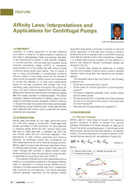
conditions (as presented in Figure 1), they react linearly<br />
to change either individually or simultaneously.<br />
Fluid flow rate defined by general textbooks suggest<br />
the following:<br />
Q = U A { . A c< rf oc D~<br />
U ex N · rz ex N · D2<br />
Equation 2a<br />
Equation 2b<br />
However, empirical data shows that flow rate to be<br />
directly proportional to diameter <strong>and</strong> speed change. The<br />
following was proposed by A.J. Stepanoff <strong>and</strong> suggest csJ<br />
its validity <strong>for</strong> a considerable range of specific speeds 2 .<br />
Q c
FEATURE<br />
4.0 EVALUATION OF FAN LAWS<br />
4.1 Effect of Scaling I Similitude<br />
In order to accurately apply <strong>Affinity</strong> <strong>Laws</strong>. G ullich suggested<br />
that geometrical <strong>and</strong> dynamic similarity be maintained; to<br />
be more specific. all wetted parts are sealed in the same<br />
ratio whilst ensuring constant Euler. Froude <strong>and</strong> Reynolds<br />
number C 6 l. The effects of Froude 4 <strong>and</strong> Reynolds 5 number<br />
<strong>for</strong> pumps are however. generally negligible unless detailed<br />
loss investigation is required. Jacques <strong>and</strong> Florjancic<br />
both added to these recommendations by implying that<br />
<strong>Affinity</strong> <strong>Laws</strong> can be applied accurately by maintaining<br />
pumps efficiency. specific <strong>and</strong> suction specific speed r 4 l.<br />
C 3 l. Jacques further suggested that only the same impeller<br />
<strong>and</strong> not one geometrically similar be used <strong>for</strong> scaling as<br />
manufacturing variation on wetted parts surface properties<br />
will affect the accuracy of <strong>Affinity</strong> <strong>Laws</strong> r 4 1 (refer Section<br />
4.1.1 <strong>for</strong> further in<strong>for</strong>mation).<br />
By paraphrase. conservation of fluid impeller exit angle<br />
be<strong>for</strong>e <strong>and</strong> after modifications would ensure the accuracy<br />
of <strong>Affinity</strong> <strong>Laws</strong>. The requirements outlined are to ensure<br />
that flow kinematics are maintained which prevents<br />
variation in slip. As illustrated be<strong>for</strong>eh<strong>and</strong> in Section<br />
3.2. observation suggests that variation in impeller outer<br />
diameter <strong>and</strong> rotational speed are major factors which<br />
govern corresponding change in the pumps per<strong>for</strong>mance.<br />
The following sub-sections will elaborate the effect of<br />
variation in these parameters on pump per<strong>for</strong>mance.<br />
4.1.11mpeller Diameter Variation<br />
It is common practice with most pump vendors to<br />
construct impellers to be slightly larger than theoretically<br />
computed. as rated flow within 80% - 110% of BEP is<br />
generally acceptable rn If required pump per<strong>for</strong>mance<br />
modifications are carried out by trimming the impeller<br />
or throttling the flow. This practice provides a buffer <strong>for</strong><br />
the minor effects neglected during detailed engineering<br />
calculations <strong>and</strong> also safeguard against under tolerance<br />
in contractual terms. Developing an impeller to its exact<br />
theoretical calculated size might prove to be detrimental<br />
commercially <strong>and</strong> to the delivery schedule. if the flow<br />
properties end up not meeting process requirements <strong>and</strong><br />
remanufacturing is required.<br />
However. one should take note that throttling the flow<br />
would mean the pump is over-sized. leading to detrimental<br />
effects. <strong>and</strong> to name a few:<br />
Higher manufacturing <strong>and</strong> operation cost<br />
Higher energy consumption as the pump would be<br />
running on part load (due to reduced pump efficiency)<br />
Higher maintenance cost <strong>and</strong> frequency (due to<br />
premature wear)<br />
Possibility of pulsation (if inducers or suction impellers<br />
are used to reduce the higher NPSHr of a larger pump)<br />
Higher possibility of seal failure<br />
Higher vibrations <strong>and</strong> noise levels (d ue to part load<br />
operation) (J)<br />
Reducing impeller diameter on the other h<strong>and</strong> does<br />
not significantly cost any of the be<strong>for</strong>e mentioned side<br />
effects besides the higher capital cost; if per<strong>for</strong>med<br />
properly <strong>and</strong> within the allowable range. Most literatures<br />
would suggest the upper limit of the allowable range to<br />
be 20% of maximum diameter. whereas some propose it<br />
to be up to 30% of maximum impeller diameter. However.<br />
in practice it is often t rimmed to about 3% - 5% 6 only of<br />
maximum impeller diameter. Further impeller trim beyond<br />
the allowable range might cause considerable efficiency<br />
drop <strong>and</strong> unstable pump per<strong>for</strong>mance due to increase in<br />
energy loss to turbulent flow. In addition. if the impeller to<br />
casing ratio exceeds the pump design limit. an excessive<br />
increment of specific vane loading would occur. resulting<br />
in re-circulation flow distribution pattern across the impeller<br />
exit to become highly unstable increasing the tendency of<br />
back flow in the pump especially in high energy <strong>and</strong> double<br />
suction flow pumps Cll.<br />
Also <strong>Affinity</strong> <strong>Laws</strong> can be easily applied to estimate the<br />
amount of trim required <strong>for</strong> a desired flow property with a<br />
caveat that the results by using this Law does not accurately<br />
reflect actual physical data. Reasons <strong>for</strong> this occurrence<br />
are breached to the geometrical similitude. be<strong>for</strong>e <strong>and</strong> after<br />
the impeller trim. Factors which contribute to this include<br />
failure of geometrical impeller trim to vary proportionally<br />
with:<br />
Impeller surface roughness (commonly negligible with<br />
the exception to application of <strong>Affinity</strong> Law in hig h head<br />
or flow operations (3))<br />
Impeller width <strong>and</strong> internal leakage clearances<br />
Impeller to casing ratio<br />
These mentioned factors cause increase in slip. wh ich<br />
evidently changes the angle of relative fluid exit velocity.<br />
Due to this. im peller diameters are often trimmed in<br />
phases of small increments <strong>and</strong> re-tested until desired flow<br />
conditions are achieved. Each time the impeller is t rimmed<br />
it would require to be re-balanced which could results in<br />
costly modifications.<br />
A silver lining to the setbacks introduced by the usage of<br />
<strong>Affinity</strong> <strong>Laws</strong> was proposed by Bloch <strong>and</strong> Budris as illustrated<br />
by Figure 2; a correction chart <strong>for</strong> im peller diameter trim<br />
to compensate <strong>for</strong> hydrau lic mismatches <strong>and</strong> mechanical<br />
imperfections C 8 l;C 9 l Validity of th is chart has been tested with<br />
two separate pump vendor per<strong>for</strong>mance curves <strong>and</strong> initial<br />
observation shows that improvement of accuracy ranging<br />
between 0.2 to approximately 10%. More importantly. usage<br />
of the correction factor as indicated in Figure 3 <strong>and</strong> Figure 4<br />
prevents impeller over cut. which is not correctable unless<br />
by change of impeller or variation of rotational speed. The<br />
question that lies here is what if the driver is not varia ble<br />
speed. which is the common case in most scenarios where<br />
impeller trimming is practiced . Do note however. even with<br />
the usage of the correction factor the exact required trim is<br />
not indicated with negligible effects. this is especially the<br />
case when referri ng to Figure 3. This is highly likely owed<br />
to the high flow of this pu mp in which the usage of these<br />
laws is highly not recommended as addressed later. Note<br />
22 1 JURUTERA June 2013
FEATURE<br />
100<br />
Impeller Correction<br />
~<br />
:~II 90<br />
0<br />
0<br />
'0,0;.<br />
~ so<br />
ffi<br />
i5<br />
{ 7o<br />
.:1<br />
.<br />
~<br />
~ 60<br />
5<br />
so .--<br />
60 100<br />
Figure 2: lfiY)eller trim correction {ll'nli(Je ado/Xedfrom(9); (8)/.<br />
however. the mere 0.01% deviation <strong>for</strong> an approximately<br />
20% maximum impeller diameter trim <strong>for</strong> pump vendor 8<br />
as demonstrated on Figure 4. which is likely owed to its<br />
moderate flow <strong>and</strong> head (medium range specific speed).<br />
Other methods that may also be applied to make impeller<br />
trimming more favourable is trimming of vanes in an oblique<br />
cut in51.ead of the entire shroud (<strong>for</strong> closed impeller designs).<br />
This reduces the effect of balancing issues <strong>and</strong> provides a<br />
more uni<strong>for</strong>m exit flow at the impeller exit. However. care<br />
also should be taken when pertorming this to ensure that<br />
shroud mechanical strength is not compromised.<br />
It is safe to pertorm interpolation of actual flow data<br />
being utilised (vendor to test <strong>and</strong> validate impeller with<br />
similar specific speed at varying sizes). <strong>and</strong> extrapolation<br />
under any circumstances avoided. If a new impeller is<br />
to be purchased to increase head or flow con ditions. a<br />
complete hydraulic analysis is recommended . The failure<br />
of the correction factor when extrapolated is indicated on<br />
Figure 3. showing an undersized impeller. which would<br />
ultimately lead to dissatisfactory pump pertormance. Pump<br />
underpertormance or over sizing is to be expected if the<br />
, .<br />
Comparl~n of Afflnlty Law Usa&e <strong>for</strong><br />
Diamet er Trim wl~h <strong>and</strong> w ithout Correct ion<br />
factor<br />
...<br />
..l. •••<br />
"' JIO<br />
...<br />
, -. ....-.....- --"'<br />
c ..... ,..,<br />
·-·~-·~·-<br />
--•fl - tt-tO \\'1<br />
, ..<br />
••<br />
'"<br />
••<br />
..<br />
,., ............ . --i•lnth:.h'•il lil.4filttlt - l .. 1ro tnl thn~t<br />
FigU!e 3: COfiY)81ison with <strong>and</strong> witho/1 correction factor proposed on<br />
general vendor A pufiY) curve (Sf Speclic Speed: 762)<br />
••<br />
..<br />
24 I JURUTERA June2013
FEATURE<br />
Comparison of Affioi ty law U~e <strong>for</strong><br />
Oiarn•terTrim with <strong>and</strong> without (Ol'r@ctlon<br />
Factor<br />
150 ------.. 100<br />
300<br />
250<br />
-200<br />
E<br />
"'150<br />
100<br />
50<br />
• •<br />
10<br />
--:15<br />
fatd Po.ioo<br />
20 lt ~ so 60 ,. :o ,.<br />
Q""'). HI<br />
-- ~ ,;.n<br />
- Caltubud ....tfinfh<br />
90<br />
so<br />
TO<br />
.;o ;.<br />
~~<br />
v<br />
•o .... •<br />
10<br />
0<br />
Figtlffl 4: Comparison ~h<strong>and</strong> ttiltootcom!dion factor prcpOftfl O"t t;tneral .errdor 8 puMp<br />
wr~ (SI Specifb Speed: 287)<br />
process condkions are extrapolated beyord a certain flow threshold.<br />
Anolller Important fimlation to consider is llle applicable specific<br />
spee:l range which <strong>Affinity</strong> <strong>Laws</strong> govern. <strong>Pumps</strong> wtlll low specific speed<br />
are desagne:l to maintain the impeler clearance wtdlll <strong>for</strong> a considerable<br />
diStance away from the outer diameter: lllis disrupts llle wtdlll to diameter<br />
"lbO wlloch maintains a near constant change as seen in middle mnge<br />
specitic spee:l pumps. High specifoc spee:l pu!Tl)s on llle olller hard have<br />
very shOrt blades. Hence. they are very sensitive to doameter changel'l due<br />
to possobllly of inadequate vane overlap causing h}
FEATURE<br />
110G<br />
1000<br />
900<br />
<strong>Affinity</strong> l aw <strong>for</strong> Rotat ional Speed Varia tion<br />
tOO<br />
I 1oo --+-?'~:;;::::_<br />
"' bOO<br />
140<br />
1 u u ; , ,.,,. atrt t


