

csm heater:CL - Vertical Mount Heater.qxd.qxd - Hotstart
csm heater:CL - Vertical Mount Heater.qxd.qxd - Hotstart
csm heater:CL - Vertical Mount Heater.qxd.qxd - Hotstart

Create successful ePaper yourself
Turn your PDF publications into a flip-book with our unique Google optimized e-Paper software.
Installation Instructions<br />
216229-000 rev-2<br />
CSM Circulating System<br />
Customer Support<br />
(509) 536-8660<br />
sales@hotstart.com<br />
www.hotstart.com<br />
READ CAREFULLY FOR PROPER INSTALLATION & OPERATION<br />
When ordering replacement parts,<br />
be sure to have your specific model number.<br />
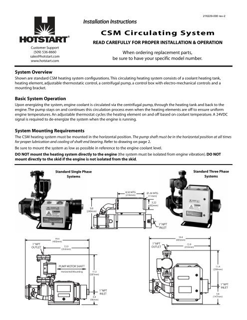
System Overview<br />
Shown are standard CSM heating system configurations. This circulating heating system consists of a coolant heating tank,<br />
heating element, adjustable thermostatic control, a centrifugal pump, a control box with electro-mechanical controls and a<br />
mounting bracket.<br />
Basic System Operation<br />
Upon energizing the system, engine coolant is circulated via the centrifugal pump, through the heating tank and back to the<br />
engine. The pump stays on and continues this circulation process even when the heating elements are off to ensure uniform<br />
engine temperatures. An adjustable thermostat cycles the heating element on and off based on coolant temperature. A 24VDC<br />
signal is required to de-energize the system when the engine is running.<br />
System <strong>Mount</strong>ing Requirements<br />
The CSM heating system must be mounted in the horizontal position. The pump shaft must be in the horizontal position at all times<br />
for proper lubrication and cooling of shaft end bearing. Refer to drawing on page 2.<br />
Be sure to mount the system as low as possible in reference to the engine coolant level.<br />
DO NOT mount the heating system directly to the engine (the system must be isolated from engine vibration). DO NOT<br />
mount directly to the skid if the engine is not isolated from the skid.<br />
Standard Single Phase<br />
Systems<br />
Standard Three Phase<br />
Systems
System Installation<br />
Typical CSM installation<br />
— Coolant Supply Line —<br />
Connect a MINIMUM 1-inch N.P.T. coolant<br />
supply hose or pipe from the main coolant<br />
drain of the engine to the inlet of the<br />
heating system. Drawing coolant from a<br />
location low in the coolant system will<br />
ensure head pressure to the pump. The<br />
supply line must remain level or angle<br />
downward to eliminate air pockets. When<br />
approaching a plumbing obstacle, go<br />
around the obstacle instead of over it.<br />
— Coolant Discharge Line —<br />
Connect a MINIMUM 1-inch N.P.T. coolant<br />
return hose or pipe from the outlet of the<br />
CSM to the highest possible location on<br />
the engine coolant system at the furthest<br />
possible location from the suction line.<br />
This connection enables heated coolant to be circulated through the entire engine.<br />
NOTE:<br />
NOTE:<br />
Your system may be configured with optional, non-restrictive shut-off valves in the coolant lines allowing<br />
maintenance on the heating system without draining the engine coolant. Isolation Valves - PRP203011-000<br />
If the heating system is plumbed with rigid pipe, use flexible lines near the heating system long enough to provide<br />
freedom from vibration in all directions.<br />
Coolant Requirements<br />
The heating system is designed for use with a 50/50 mixture of low-silicate antifreeze and distilled water. Pre-mixed products are<br />
recommended. If not using a pre-mixed solution, ensure that the liquids are well mixed prior to filling the engine’s cooling system.<br />
Do not exceed a concentration of more than 60% antifreeze as element failure can result.<br />
NOTE:<br />
After the heating system is mounted and the engine is refilled with coolant, loosen outlet flange at pump to bleed<br />
the air out of the system. DO NOT ENERGIZE THE HEATING SYSTEM AT THIS TIME. Run the engine until it reaches<br />
normal operating temperature to eliminate trapped air that may still be present in the engine.<br />
System Wiring<br />
OPERATION OF THE SYSTEM DURING ENGINE OPERATION MAY CAUSE DAMAGE TO THE HEATER.<br />
THE HEATING ELEMENT PACKAGE IS PRE-WIRED SPECIFIC TO THE SYSTEM WATTAGE AND VOLTAGE.<br />
ALTERING THE SUPPLIED WIRING CONFIGURATION CAN RESULT IN HEATER FAILURE.<br />
ALL CONNECTIONS IN THE JUNCTION BOX SHOULD BE CHECKED DURING INSTALLATION. VIBRATION<br />
DURING SHIPMENT CAN CAUSE SCREWS TO LOOSEN. ALL CONNECTIONS IN THE JUNCTION BOX<br />
SHOULD BE CHECKED AT ENGINE SERVICE INTERVALS. VIBRATION CAN CAUSE CONNECTIONS TO<br />
LOOSEN.<br />
WIRING TO HEATING SYSTEM TO BE PERFORMED BY A QUALIFIED ELECTRICIAN AND CONFORM TO<br />
ALL NATIONAL, STATE AND LOCAL ELECTRICAL CODES.<br />
DISCONNECT ALL POWER SOURCES PRIOR TO PERFORMING ANY MAINTENANCE ON THE HEATING<br />
SYSTEM<br />
2
Main Power Wiring<br />
Connect the specified voltage and phase to the terminal blocks located in the main control box of the heating system. A usersupplied<br />
circuit breaker (rated at the appropriate amperage) is required for use in the main power feed line. For 3 phase<br />
applications, the terminal blocks are labeled L1, L2 and L3. For single phase applications, use terminal blocks labeled L1 and L2<br />
(2-pole contactor, no transformer) or L1 and L3 (3-pole contactor, with transformer).<br />
24 VDC Shutdown<br />
Connect a user-supplied source of 24 VDC electricity to the terminal blocks labeled A1 and A2 in the control box. When present,<br />
this 24 VDC shutdown signal will disable the heating system to prevent operation while the engine is running.<br />
The standard heating systems are wired such that the relay is normally closed (a 24 VDC signal when the engine is running<br />
disables the heating system).<br />
Standard Single Phase<br />
Systems<br />
Standard Three Phase<br />
Systems<br />
GROUND LUG<br />
FOR POWER IN<br />
(see notes)<br />
24VDC RELAY<br />
CONTROL<br />
CONNECTIONS<br />
A1, A2 (see notes)<br />
POWER IN<br />
CONNECTIONS<br />
L1, L2 (see notes)<br />
CONTACTOR<br />
50AMP<br />
240V<br />
TRANSFORMER<br />
24VDC RELAY<br />
CONTROL CONNECTIONS<br />
A1, A2 (see notes)<br />
GROUND LUG<br />
FOR POWER IN<br />
(see notes)<br />
POWER IN<br />
CONNECTIONS<br />
L1, L2, L3<br />
FUSES,<br />
2AMP<br />
MAGNETIC<br />
CONTACTOR<br />
FUSES 2AMP<br />
PRIMARY<br />
NOTES<br />
A1, A2 TORQUE: 4.4 in-lbs (0.5 N-m)<br />
L1, L2 TORQUE IF BINDING SCREW: 20 in-lbs (2.3 N-m)<br />
L1, L2 TORQUE IF LUG: 40 in-lbs (4.5 N-m)<br />
GROUND LUG TORQUE: 6.4 in-lbs (0.7 N-m)<br />
24VDC RELAY<br />
NOTES<br />
A1, A2 TORQUE: 4.4 in-lbs (0.5 N-m)<br />
GROUND LUG TORQUE: 6.4 in-lbs (0.7 N-m)<br />
FUSES 2AMP<br />
SECONDARY<br />
3
System Start-Up Check List<br />
After system installation has been completed, follow these<br />
steps for proper coolant heating system start-up.<br />
Step 1 Check and tighten all electrical and plumbing<br />
connections.<br />
Adjustable<br />
Thermostat<br />
3 Phase<br />
OPERATION OF HEATING SYSTEM<br />
WITH <strong>CL</strong>OSED ISOLATION VALVES<br />
COULD RESULT IN SERIOUS INJURY<br />
Step 2 Ensure isolation valves are open before starting<br />
system.<br />
Step 3 After the heating system is mounted and the engine<br />
is refilled with coolant, loosen outlet flange at pump<br />
to bleed the air out of the system. DO NOT ENERGIZE<br />
THE HEATING SYSTEM AT THIS TIME. Run the engine<br />
until it reaches normal operating temperature to<br />
eliminate trapped air that may still be present in the<br />
engine’s cooling system.<br />
Step 4 Standard systems are equipped with an adjustable<br />
thermostat that is factory pre-set at 110°F. Verify that<br />
the thermostat is set as desired prior to operation. The thermostat is located in the element enclosure shown at right.<br />
Optional CSM Configurations Without Controls<br />
For these systems, the end user/installer is responsible for providing the necessary controls needed to operate the <strong>heater</strong>s per the<br />
wiring diagrams on page 2. The system thermostat cycles the heating element on and off. When the heating system is energized,<br />
the pump should run continuously. An appropriate shut-off device must be in place to de-engergize the heating system upon<br />
engine start-up.<br />
22.8<br />
(579mm)<br />
28.4<br />
(721mm)<br />
CSM without Controls<br />
(Pump at Inlet)<br />
5.5<br />
(140mm)<br />
3.2<br />
(81mm)<br />
13.9<br />
(353mm)<br />
CSM without Controls<br />
(Pump at Outlet)<br />
11.4<br />
(289mm)<br />
13.7<br />
(345mm)<br />
19.4<br />
(493mm)<br />
4


