Constructing droplet interface bilayers from the ... - Wallace Lab
Constructing droplet interface bilayers from the ... - Wallace Lab
Constructing droplet interface bilayers from the ... - Wallace Lab

Create successful ePaper yourself
Turn your PDF publications into a flip-book with our unique Google optimized e-Paper software.
protocol<br />
<strong>Constructing</strong> <strong>droplet</strong> <strong>interface</strong> <strong>bilayers</strong> <strong>from</strong> <strong>the</strong><br />
contact of aqueous <strong>droplet</strong>s in oil<br />
Sebastian Leptihn 1,3 , Oliver K Castell 1 , Brid Cronin 1 , En-Hsin Lee 2 , Linda C M Gross 1 , David P Marshall 1 ,<br />
James R Thompson 1,3 , Mat<strong>the</strong>w Holden 2 & Mark I <strong>Wallace</strong> 1<br />
1 Department of Chemistry, Oxford University, Oxford, UK. 2 Department of Chemistry, University of Massachusetts, Amherst, Massachusetts, USA. 3 Present addresses:<br />
Institute for Microbiology and Molecular Biology, University of Hohenheim, Stuttgart, Germany (S.L.); Mork Family Department of Chemical Engineering and Materials and<br />
Molecular Biology, University of Sou<strong>the</strong>rn California, Los Angeles, California, USA (J.R.T.). Correspondence should be addressed to M.I.W. (mark.wallace@chem.ox.ac.uk).<br />
Published online 2 May 2013; doi:10.1038/nprot.2013.061<br />
© 2013 Nature America, Inc. All rights reserved.<br />
We describe a protocol for forming an artificial lipid bilayer by contacting nanoliter aqueous <strong>droplet</strong>s in an oil solution in <strong>the</strong><br />
presence of phospholipids. A lipid monolayer forms at each oil-water <strong>interface</strong>, and when two such monolayers touch, a bilayer is<br />
created. Droplet <strong>interface</strong> <strong>bilayers</strong> (DIBs) are a simple way to generate stable <strong>bilayers</strong> suitable for single-channel electrophysiology<br />
and optical imaging <strong>from</strong> a wide variety of preparations, ranging <strong>from</strong> purified proteins to reconstituted eukaryotic cell membrane<br />
fragments. Examples include purified proteins <strong>from</strong> <strong>the</strong> a-hemolysin pore <strong>from</strong> Staphylococcus aureus, <strong>the</strong> anthrax toxin pore and<br />
<strong>the</strong> 1.2-MDa mouse mechanosensitive channel MmPiezo1. Ion channels and ionotropic receptors can also be reconstituted <strong>from</strong><br />
membrane fragments without fur<strong>the</strong>r purification. We describe two approaches for forming DIBs. In one approach, a lipid bilayer is<br />
created between two aqueous <strong>droplet</strong>s submerged in oil. In <strong>the</strong> o<strong>the</strong>r approach, a membrane is formed between an aqueous <strong>droplet</strong><br />
and an agarose hydrogel, which allows imaging in addition to electrical recordings. The protocol takes
protocol<br />
© 2013 Nature America, Inc. All rights reserved.<br />
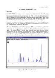
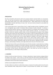
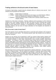
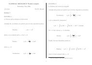
Figure 1 | Images illustrating <strong>the</strong> formation of<br />
<strong>droplet</strong>-<strong>droplet</strong> <strong>bilayers</strong> and <strong>droplet</strong>-hydrogel<br />
<strong>bilayers</strong>. (a) Agarose is pipetted onto <strong>the</strong> ends<br />
of two Ag/AgCl electrodes and submerged in<br />
hexadecane, 200 nl of vesicle solution are<br />
pipetted onto <strong>the</strong> agarose, <strong>the</strong> <strong>droplet</strong>s move<br />
down on <strong>the</strong> electrodes once a lipid monolayer<br />
has been formed, and <strong>the</strong> electrodes are<br />
manipulated to bring <strong>the</strong> <strong>droplet</strong>s into contact<br />
and form a bilayer. (b) Agarose substrate is<br />
prepared by spin-coating 0.75% (wt/vol) agarose<br />
onto a glass coverslip and <strong>the</strong>n assembling a<br />
PMMA device and filling it with rehydrating<br />
agarose, lipid in oil is added to <strong>the</strong> device and a<br />
monolayer assembles at <strong>the</strong> agarose oil <strong>interface</strong>,<br />
a <strong>droplet</strong> that has been prepared under lipid in<br />
oil is pipetted into <strong>the</strong> device, <strong>the</strong> <strong>droplet</strong> falls<br />
under gravity and contacts <strong>the</strong> surface to form a<br />
bilayer, and an Ag/AgCl electrode is inserted into<br />
<strong>the</strong> <strong>droplet</strong> using a micromanipulator. Fluorescent<br />
species at <strong>the</strong> bilayer can be investigated using<br />
optical microscopy. Scale bars, 200 µm.<br />
<strong>the</strong> two <strong>droplet</strong>s. This is quicker and easier to achieve than conventional<br />
patch clamping, in which <strong>the</strong> careful manipulation of a<br />
micropipette to a cell or vesicle surface, followed by gentle suction,<br />
is required to form a gigaseal, which is not always successful.<br />
Supported lipid <strong>bilayers</strong> produced by fusing vesicles on a<br />
glass surface 1,11 or by using <strong>the</strong> Langmuir-Blodgett deposition<br />
method 52,53 have been widely used for optical imaging of artificial<br />
<strong>bilayers</strong>. However, considerable care must be taken to limit<br />
substrate interaction with <strong>the</strong> bilayer and also to produce homogenous<br />
defect-free <strong>bilayers</strong> 54 . In contrast, DIBs are inherently defect<br />
free, and single-particle tracking of labeled lipids in a DIB formed<br />
between a <strong>droplet</strong> and an agarose substrate shows diffusion coefficients<br />
similar to an unsupported bilayer 47 . GUVs provide ano<strong>the</strong>r<br />
alternative model membrane that can be generated using gentle<br />
hydration 55 , electroformation 56 or o<strong>the</strong>r methods 18 . GUVs have<br />
<strong>the</strong> advantage of not requiring a substrate, but <strong>the</strong>y require careful<br />
connection to a micropipette to access <strong>the</strong> vesicle interior.<br />
O<strong>the</strong>r miniaturized technologies for <strong>the</strong> development of artificial<br />
lipid <strong>bilayers</strong> have recently been reviewed 29,39,57–60 . For highthroughput<br />
screening, DIBs are straightforward to parallelize, and<br />
<strong>the</strong>ir automated generation is possible. Networks of DIBs could<br />
a<br />
b<br />
Prepare electrodes Add <strong>droplet</strong>s Droplets sag Bilayer forms<br />
Spin-coat hydrogel Add oil/lipids Add <strong>droplet</strong> Bilayer forms Add electrode<br />
also be used to create biological equivalents of electronic devices 21 .<br />
The evolution of <strong>the</strong> DIB technique is still ongoing, but <strong>the</strong> method<br />
has matured to a stage in which it represents a valuable alternative<br />
to o<strong>the</strong>r artificial lipid bilayer techniques because of its simplicity,<br />
robustness and versatility.<br />
Experimental design<br />
There are a number of different possible experimental configurations<br />
for producing a DIB. The primary difference lies in whe<strong>the</strong>r<br />
<strong>the</strong> bilayer is formed between two <strong>droplet</strong>s or between a <strong>droplet</strong><br />
and a hydrogel support. For both of <strong>the</strong>se methods, <strong>bilayers</strong> can<br />
be formed using lipids present ei<strong>the</strong>r in <strong>the</strong> oil phase or as vesicles<br />
within <strong>the</strong> aqueous phase. To highlight this flexibility, we have<br />
chosen to describe two examples of our method: <strong>droplet</strong>-<strong>droplet</strong><br />
<strong>bilayers</strong> formed with lipids present as vesicles within <strong>the</strong> aqueous<br />
<strong>droplet</strong> and <strong>droplet</strong>-hydrogel <strong>bilayers</strong> formed <strong>from</strong> lipids<br />
present in <strong>the</strong> oil phase. The steps describing <strong>the</strong>se two configurations<br />
are shown in Figure 1. Examples for two applications,<br />
measuring protein transport across DIBs and optical and electrical<br />
recordings <strong>from</strong> channels in DIBs, are described in Boxes 1<br />
and 2, respectively.<br />
xyz<br />
- V<br />
Box 1 | Measuring protein transport across DIB<br />
The transport of analytes <strong>from</strong> one <strong>droplet</strong> to ano<strong>the</strong>r across <strong>the</strong> bilayer can be monitored. In this case, one can monitor <strong>the</strong><br />
N-terminal domain of <strong>the</strong> anthrax lethal factor (LF N ) after translocation through <strong>the</strong> protective antigen (PA) pore 20 .<br />
Droplet preparation: Ag/AgCl electrodes coated in agarose are immersed in a solution of lipid in hexadecane. A 200-nl <strong>droplet</strong><br />
solution containing PA and LF N is added to one of <strong>the</strong> electrodes to form <strong>the</strong> ‘reservoir’ <strong>droplet</strong>. ‘Reservoir’ and ‘capture’ <strong>droplet</strong>s are<br />
contacted and a bilayer is formed, followed by insertion of PA pores. Bilayers form with typically low failure rates ( < 5%).<br />
Cargo transport: A potential is applied across <strong>the</strong> bilayer using <strong>the</strong> electrodes. After <strong>the</strong> translocation of LF N , <strong>the</strong> <strong>droplet</strong>s are<br />
separated.<br />
Readout: The reservoir <strong>droplet</strong> is discarded. A detection <strong>droplet</strong> is formed by adding 200 nl of bilayer buffer to a new agarose-coated<br />
electrode. A volume of 200 nl of diluted PA is added to <strong>the</strong> capture <strong>droplet</strong>, and a DIB is formed with <strong>the</strong> detection <strong>droplet</strong>. After PA<br />
insertion into <strong>the</strong> membrane, blockage of <strong>the</strong> ionic current through pores by cargo <strong>from</strong> <strong>the</strong> capture <strong>droplet</strong> is monitored at <strong>the</strong><br />
single-pore level.<br />
nature protocols | VOL.8 NO.6 | 2013 | 1049
protocol<br />
Box 2 | Optical and electrical recording <strong>from</strong> channels in DIB<br />
© 2013 Nature America, Inc. All rights reserved.<br />
Both single-channel electrophysiology and single-molecule fluorescence imaging can be performed simultaneously using DIBs. Here we<br />
describe <strong>the</strong> use of this protocol to study <strong>the</strong> pore-forming toxin α-hemolysin <strong>from</strong> S. aureus 25 .<br />
Protein sample preparation: A C-terminal single cysteine mutant of α-hemolysin monomer is recombinantly expressed in Escherichia<br />
coli before chemical labeling with Cy3b maleimide.<br />
Device preparation: Agarose is spin-coated onto a microscope coverslip and covered with a micromachined PMMA device. Channels<br />
within this device are filled with molten agarose and allowed to cool and gel. A solution of lipid in hexadecane is pipetted into wells<br />
present in <strong>the</strong> device and incubated for ~15 min. This device ensures that <strong>the</strong> agarose remains hydrated, and it also provides a well to<br />
contain <strong>the</strong> oil solution.<br />
Droplet preparation: Aqueous <strong>droplet</strong>s of ~100 pM α-hemolysin are allowed to equilibrate for 15 min in a solution of lipid in<br />
hexadecane to form lipid monolayers at <strong>the</strong> oil-water <strong>interface</strong>. A <strong>droplet</strong> is pipetted into each well; <strong>the</strong> <strong>droplet</strong> sinks to <strong>the</strong> substrate<br />
agarose layer at <strong>the</strong> bottom of <strong>the</strong> well, and it <strong>the</strong>n forms a bilayer. Bilayers form with typically low failure rates (< 5%). α-hemolysin<br />
assembles to form a heptameric pore in <strong>the</strong> bilayer.<br />
Electrophysiology: A 100-µm-diameter Ag/AgCl electrode is inserted into <strong>the</strong> <strong>droplet</strong> using a micromanipulator. By using a<br />
corresponding Ag/AgCl ground electrode in <strong>the</strong> agarose, ionic currents <strong>from</strong> single pores present in <strong>the</strong> bilayer can be recorded.<br />
Single-molecule fluorescence: For optical recordings, <strong>the</strong> device was placed on an inverted microscope; individual α-hemolysin<br />
pores can be detected diffusing in <strong>the</strong> bilayer by using and TIRF illumination and electron-multiplying charge-coupled<br />
device (CCD) detection.<br />
Limitations<br />
DIBs can be formed using a range of different lipid compositions<br />
44,46,49 with little variation in appearance (Fig. 2). The basic<br />
rule of thumb is that if a lipid or solvent composition can be used<br />
for a conventional lipid bilayer experiment, it can be easily adapted<br />
to <strong>the</strong> DIB technique.<br />
The major limitations that we have investigated include <strong>the</strong><br />
following:<br />
• Lipid location. Bilayers form more rapidly<br />
when vesicles are present within <strong>the</strong><br />
aqueous phase; however, for some experiments,<br />
<strong>the</strong> presence of vesicles within <strong>the</strong><br />
<strong>droplet</strong> may be undesirable.<br />
• Lipid concentration. When <strong>the</strong> lipids are<br />
present in <strong>the</strong> oil phase, <strong>the</strong> bilayer formation<br />
rate is dependent on lipid concentration.<br />
Below a concentration of<br />
2 mg ml − 1 , <strong>the</strong>re is typically insufficient<br />
lipid to form a monolayer, and <strong>droplet</strong>s<br />
will immediately coalesce without bilayer<br />
formation. Above a concentration of 10 mg ml − 1 , bilayer formation<br />
times are markedly increased.<br />
• Detergent concentration. As with all bilayer systems, <strong>the</strong> presence<br />
of detergent will disrupt <strong>the</strong> bilayer and potentially compromise<br />
stability. We have found that 1,2-diphytanoyl-sn-glycero-3-<br />
phosphocholine (DPhPC) DIBs may tolerate up to 0.01%<br />
(wt/vol) n-decyl-β-d-maltopyranoside in <strong>the</strong> aqueous <strong>droplet</strong>.<br />
a b c<br />
d e f<br />
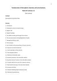
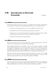
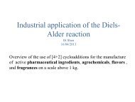
Figure 2 | Bright-field images of <strong>droplet</strong><br />
<strong>bilayers</strong> formed under various lipid conditions.<br />
The darkest area in each image is <strong>the</strong> tip of <strong>the</strong><br />
Ag/AgCl electrode. (a) DPhPC in hexadecane.<br />
(b) DPhPC in tetradecane. (c) DPhPC in decane.<br />
(d) DPhPC:cholesterol (3:2) in hexadecane.<br />
(e) DPhPC:DOPG (9:1) in hexadecane. (f) DOPE:<br />
DOPG (4:1) in hexadecane. (g) DPhPC:DPPC:<br />
cholesterol (1:1:1) in hexadecane. (h) DPhPC/<br />
DPhPC:DPPC:cholesterol (1:1:1) in hexadecane.<br />
(i) DOPC:DPPC:cholesterol (3:1:1)/DOPC in<br />
hexadecane. In <strong>the</strong> examples above, <strong>droplet</strong>s appear<br />
as dark circles corresponding to <strong>the</strong> perimeter of <strong>the</strong><br />
<strong>droplet</strong>. The bilayer can be seen as a white ring. The<br />
irregular out of focus black object in each image is<br />
<strong>the</strong> electrode with agarose anchor. Scale bar, 75 µm.<br />
g h i<br />
1050 | VOL.8 NO.6 | 2013 | nature protocols
protocol<br />
• Applied potential. As with o<strong>the</strong>r planar lipid <strong>bilayers</strong>, high<br />
applied potentials ( >150–200 mV) can cause electroporation<br />
and eventually rupture <strong>the</strong> bilayer.<br />
• Osmotic pressure. As with o<strong>the</strong>r <strong>bilayers</strong>, DIB integrity is influenced<br />
by <strong>the</strong> osmotic gradient across <strong>the</strong> bilayer. At higher osmolyte<br />
concentrations, <strong>droplet</strong>s form lipid <strong>bilayers</strong> more readily and<br />
are more stable compared with <strong>droplet</strong>s of a lower ionic strength.<br />
Although it has not been exhaustively explored, we have found<br />
that DIBs are able to withstand osmotic gradients of 50 atm.<br />
• Temperature. DIBs do not tolerate freezing of <strong>the</strong> oil (<strong>the</strong><br />
freezing point of hexadecane is 18 °C). DIBs can be used at<br />
higher temperatures, and our experiments on planar supports<br />
show that <strong>bilayers</strong> are stable up to <strong>the</strong> melting temperature of<br />
<strong>the</strong> agarose.<br />
• Residual solvent. Capacitance measurements 44 show that <strong>the</strong><br />
proportion of residual solvent present in <strong>the</strong> bilayer depends<br />
on <strong>the</strong> similarity between lipid chain length and solvent<br />
structure, as one would expect for a Montal-Mueller bilayer<br />
61 . We previously calculated that DPhPC DIBs formed<br />
in hexadecane contain 9.2% oil by volume 44 . The use of lipid<br />
solutions in heptadecane or squalene produce an essentially<br />
solvent-free bilayer 44 .<br />
© 2013 Nature America, Inc. All rights reserved.<br />
MATERIALS<br />
REAGENTS<br />
CRITICAL See <strong>the</strong> Reagent Setup section for detailed preparation<br />
instructions.<br />
Agarose preparation<br />
• Agarose, low melt (Sigma-Aldrich, cat. no. A9414)<br />
Vesicle preparation<br />
• 1,2-Dipalmitoyl-sn-glycero-3-phosphocholine (DPPC, Avanti Polar Lipids,<br />
cat. no. 850355)<br />
• Chloroform (Sigma, cat. no. 650498)<br />
• Buffer solution: 100 mM KCl and 10 mM HEPES (pH 7.4, titrated<br />
with KOH)<br />
Lipid in hexadecane solution preparation<br />
• 1,2-Diphytanoyl-sn-glycero-3-phosphocholine (DPhPC; Avanti Polar<br />
Lipids, cat. no. 850356; Note that DPhPC can be replaced by o<strong>the</strong>r lipids or<br />
lipid combinations if desired)<br />
• Chloroform (Sigma, cat. no. 650498)<br />
• Hexadecane (Sigma, cat. no. H6703)<br />
Electrode preparation<br />
• Silver wire, 100 µm in diameter (Sigma, cat. no. 348783)<br />
• Silver wire, 1.5 mm in diameter (Sigma, cat. no. 348759)<br />
• Sodium hypochlorite solution (Sigma, cat. no. 425044)<br />
EQUIPMENT<br />
Experimental setting: <strong>droplet</strong>-<strong>droplet</strong><br />
• Faraday cage<br />
• Oil bath, e.g., 1-ml Perspex chamber<br />
• Micromanipulators (NMN21, Narishige)<br />
• Patch-clamp amplifier (Axopatch 200B, Axon Instruments)<br />
Vesicle preparation<br />
• Vacuum desiccator<br />
• Mini-extruder (Avanti Polar Lipids, cat. no. 610000)<br />
• Nuclepore track-etched membrane, 0.1-µm pore size, 19-mm diameter<br />
(Whatman, cat. no. 800309)<br />
Experimental setting: <strong>droplet</strong>-hydrogel<br />
• Faraday cage<br />
• Micromanipulator<br />
• Patch-clamp amplifier<br />
• Inverted microscope<br />
Lipid in hexadecane preparation<br />
• Vacuum desiccator<br />
Poly(methyl methacrylate) device and <strong>droplet</strong> incubation chamber<br />
• Extruded sheet poly(methyl methacrylate) (PMMA, 4-mm thickness<br />
(RS, cat. no. 824-519)<br />
• Subtractive computer numerical control (CNC) milling machine<br />
(e.g., Roland Modela MDX-40A)<br />
• CAD software (e.g., SolidWorks)<br />
Surface preparation<br />
• Microscope coverslips (borosilicate glass, 24 mm × 40 mm, thickness no. 1<br />
(0.13–0.16 mm); Gerhard Menzel, cat. no. BB024040A1)<br />
• Plasma cleaner (Diener Electronic, Femto)<br />
• Spin coater (3,000 r.p.m.; Laurell, cat. no. WS-650MZ-23NPP/LITE)<br />
• Adhesive tape (e.g., Scotch, 3M)<br />
Device assembly<br />
• Hot plate capable of 35 °C<br />
• Dry heat block capable of 90 °C<br />
REAGENT SETUP<br />
Droplet-<strong>droplet</strong> vesicle preparation Prepare a 50 mg ml − 1 lipid stock by dissolving<br />
DPPC in chloroform. Take 29 µl of this stock in a glass vial. While<br />
rotating <strong>the</strong> vial gently, dry <strong>the</strong> lipid solution under a stream of nitrogen until<br />
<strong>the</strong> solvent is removed and a lipid film remains. Place <strong>the</strong> vial in a vacuum desiccator<br />
for at least 30 min to remove any residual solvent. Resuspend <strong>the</strong> lipid<br />
in 1 ml of buffer and vortex <strong>the</strong> lipid for 60 s to obtain a cloudy 2 mM lipid<br />
suspension. Extrude <strong>the</strong> solution with 21 passes through a membrane filter<br />
(e.g., Avanti mini-extruder with Whatman-GE Nuclepore track-etched<br />
membranes). As illustrated in Figure 2, o<strong>the</strong>r lipids and lipid ratios can be<br />
prepared using this method. Vesicle solutions can be stored at 4 °C for 1 week.<br />
Droplet-<strong>droplet</strong> protein preparation (optional) This protocol can be<br />
adapted to incorporate membrane proteins into <strong>the</strong> DIB. Several strategies<br />
are possible, depending on <strong>the</strong> nature of <strong>the</strong> users’ protein sample. Standard<br />
protocols exist for preparation of <strong>the</strong> samples used in <strong>the</strong>se procedures. For<br />
example, membrane proteins can be first reconstituted into lipid vesicles 62,63 ,<br />
detergent-solubilized proteins can also be used 64 and proteins can also be<br />
syn<strong>the</strong>sized in <strong>the</strong> <strong>droplet</strong> 20 .<br />
Droplet-<strong>droplet</strong> agarose preparation Dissolve 30 mg of agarose in 1 ml of<br />
desired experimental buffer to produce a 3% (wt/vol) solution. This can be<br />
stored for several weeks at room temperature (22 °C).<br />
Droplet-<strong>droplet</strong> electrode preparation Briefly melt one end of a 20-mm<br />
length of 100-µm-diameter silver wire over a flame to create a silver ball<br />
of ~250 µm in diameter. Immerse <strong>the</strong> ball end of <strong>the</strong> wire in 20% (wt/vol)<br />
sodium hypochlorite solution for 30 min. A gray color indicates that a<br />
AgCl coating has formed. Two Ag/AgCl electrodes should be prepared.<br />
Solder <strong>the</strong>m to insulated cable and fit appropriate connectors for head<br />
stage (e.g., Axon Axopatch 200B). These can be used for up to 2 weeks<br />
before recoating.<br />
Droplet-hydrogel agarose preparation Dissolve 75 mg of agarose in 10 ml<br />
of deionized water to produce a 0.75% (wt/vol) solution. Dissolve 325 mg of<br />
agarose in 10 ml of <strong>the</strong> desired experimental buffer to produce 3.25% (wt/vol)<br />
solution. These can be stored for at least 2 weeks at room temperature.<br />
Droplet-hydrogel: lipid in hexadecane solution preparation Prepare a<br />
50 mg ml − 1 lipid stock by dissolving DPhPC in chloroform. Take 380 µl of<br />
this stock in a glass vial. Swirl <strong>the</strong> vial rapidly under nitrogen stream until<br />
<strong>the</strong> solvent is removed and a lipid film is formed. Place <strong>the</strong> vial in vacuum<br />
desiccator for at least 30 min to remove <strong>the</strong> solvent completely. Add 2 ml of<br />
hexadecane and vortex <strong>the</strong> vial to produce a 9.5 mg ml − 1 solution. Lipid in<br />
chloroform solution can be kept at least 1 month in a sealed vial at − 20 °C.<br />
Lipid in hexadecane is stable at room temperature.<br />
Droplet-hydrogel protein preparation (optional) Membrane proteins can<br />
also be incorporated into a <strong>droplet</strong>-hydrogel DIB by following <strong>the</strong> suggested<br />
sample preparation steps outlined above. In addition, proteins can be<br />
introduced into <strong>the</strong> lipid bilayer <strong>from</strong> <strong>the</strong> agarose support: for detergentsolubilized<br />
proteins, samples are diluted to detergent concentrations that<br />
nature protocols | VOL.8 NO.6 | 2013 | 1051
protocol<br />
do not disrupt <strong>the</strong> bilayer (for n-decyl-β-d-maltopyranoside ~0.01%,<br />
usually 1:1,000, for single-channel recordings up to 1:1,000,000). Membrane<br />
fragments can also be used 27,65 . For proteins in native cell membranes,<br />
membrane fragments or vesicles, samples are diluted (usually 1:1,000, but<br />
up to 1:1,000,000 for single-channel recordings). Before device assembly,<br />
<strong>the</strong> sample is mixed with <strong>the</strong> low-melting substrate agarose, or pipetted<br />
onto <strong>the</strong> spin-coated hydrogel substrate layer.<br />
Droplet-hydrogel electrode preparation For <strong>the</strong> ground electrode, cut a<br />
10-mm length of 1.5-mm silver wire. Solder it to 18-gauge insulated copper<br />
wire with an appropriate connector for <strong>the</strong> head stage. For <strong>the</strong> <strong>droplet</strong> electrode,<br />
cut a 20-mm length of 100-µm-diameter silver wire and solder it to<br />
insulated cable with connector for <strong>the</strong> head stage. Immerse silver portions<br />
of 1.5-mm electrode in 20% (wt/vol) sodium hypochlorite overnight, and,<br />
also, immerse <strong>the</strong> 100-µm electrode for 1 h. A gray color indicates that an<br />
AgCl coating has been formed. Electrodes need to be checked regularly for<br />
<strong>the</strong> uniformity of <strong>the</strong> Ag/AgCl coating and need to be recoated if required.<br />
As a general guideline, we are able to use electrodes for about 2 weeks<br />
before recoating.<br />
EQUIPMENT SETUP<br />
Droplet-hydrogel PMMA device manufacture This is a reusable device in which<br />
<strong>droplet</strong> hydrogel DIBs can be formed; it can be machined by CNC micromachining.<br />
An array of 1-mm-diameter holes machined in PMMA acts as chambers for<br />
<strong>the</strong> formation of individual DIBs. On <strong>the</strong> underside of <strong>the</strong> PMMA substrate, a<br />
microfluidic channel surrounding each well is machined (Fig. 3a–c).<br />
Droplet-hydrogel incubation chamber manufacture Prepare a chamber<br />
for <strong>droplet</strong> incubation by micromilling recesses of 43 mm × 27 mm ×<br />
5.5 mm into a planar PMMA substrate (Fig. 3d).<br />
Droplet-hydrogel coverslip surface preparation Plasma-clean<br />
microscope coverslips for 7 min at 95 W with a 0.5-bar<br />
oxygen stream.<br />
© 2013 Nature America, Inc. All rights reserved.<br />
PROCEDURE<br />
1| Depending on <strong>the</strong> desired application, DIBs may be generated in option A, a <strong>droplet</strong>-<strong>droplet</strong> configuration, or option B,<br />
a <strong>droplet</strong>-hydrogel format. Both approaches share a number of common steps, including coating <strong>the</strong> electrodes with agarose<br />
and mounting <strong>the</strong> Faraday cage.<br />
(A) Droplet-<strong>droplet</strong> <strong>bilayers</strong> ● TIMING 8 min<br />
(i) Preparation of oil bath chamber. Fill up an oil bath (e.g., a 1-ml Perspex chamber) with hexadecane and place this<br />
chamber, toge<strong>the</strong>r with two micromanipulators and <strong>the</strong> patch-clamp amplifier head stage, in a metal enclosure to act<br />
as a Faraday cage.<br />
(ii) Preparation of agarose-coated electrodes (Fig. 1a). Pipette 200 nl of 3% (wt/vol) agarose at 90 °C onto <strong>the</strong> end of two<br />
coated electrodes. A stereomicroscope may assist with this process. On cooling, agarose gelation generates an agarose<br />
<strong>droplet</strong> at <strong>the</strong> end of each electrode.<br />
(iii) To avoid dehydration of <strong>the</strong> agarose, submerge each <strong>droplet</strong> in <strong>the</strong> hexadecane-containing oil chamber immediately<br />
after gelation of <strong>the</strong> agarose. Attach <strong>the</strong> impaled electrode to <strong>the</strong> micromanipulator to support <strong>the</strong> agarose <strong>droplet</strong><br />
within <strong>the</strong> chamber.<br />
(iv) Application of <strong>the</strong> lipid solution to <strong>the</strong> agarose-coated electrode (Fig. 1a). By using a stereomicroscope to view <strong>the</strong><br />
<strong>droplet</strong>s, pipette 200 nl of pre-prepared vesicle solution onto each agarose <strong>droplet</strong> immersed in <strong>the</strong> oil by placing <strong>the</strong><br />
pipette tip close to <strong>the</strong> supported agarose <strong>droplet</strong>. The vesicle <strong>droplet</strong>s will adhere to <strong>the</strong> suspended hydrogel. The<br />
<strong>droplet</strong> solution can contain proteoliposomes or detergent-solubilized proteins if incorporation of membrane proteins<br />
is required.<br />
(v) Incubate <strong>the</strong> <strong>droplet</strong>s (Fig. 1a). Wait for ~2 min to allow <strong>the</strong> formation of a self-assembled lipid monolayer. It is<br />
important to give <strong>the</strong> <strong>droplet</strong>s time to form a defect-free lipid monolayer; o<strong>the</strong>rwise, <strong>droplet</strong>s tend to burst and <strong>the</strong><br />
procedure will fail. On doing so, reduction of <strong>the</strong> interfacial tension results in <strong>the</strong> <strong>droplet</strong> sagging <strong>from</strong> <strong>the</strong> electrode,<br />
indicating that <strong>the</strong> <strong>droplet</strong>s are ready to form a DIB.<br />
CRITICAL STEP Allow time for monolayer formation or <strong>droplet</strong>s will fuse when <strong>the</strong>y contact.<br />
(vi) DIB formation (Fig. 1a). By using <strong>the</strong> stereomicroscope to view <strong>the</strong> <strong>droplet</strong>s, move <strong>the</strong> micromanipulator(s) to carefully<br />
bring <strong>the</strong> two <strong>droplet</strong>s into contact. It is crucial for <strong>the</strong> formation of a bilayer to move <strong>the</strong> <strong>droplet</strong>s so that <strong>the</strong>y<br />
‘touch’, but do not push <strong>the</strong>m too close toge<strong>the</strong>r as this may result in <strong>droplet</strong> fusion and failure of <strong>the</strong> procedure.<br />
Close <strong>the</strong> lid of <strong>the</strong> metal enclosure to shield it <strong>from</strong> external electrical noise. Bilayer formation generally occurs within<br />
1 or 2 min of contacting <strong>the</strong> <strong>droplet</strong>s. Progression of <strong>the</strong> bilayer formation process may be monitored by capacitance<br />
measurement. To accelerate bilayer formation, a potential of 50 mV can be applied between <strong>the</strong> electrodes.<br />
CRITICAL STEP Droplets must be repositioned carefully or <strong>the</strong>y will fuse when <strong>the</strong>y contact.<br />
? TROUBLESHOOTING<br />
(vii) Adjust bilayer size (optional). Micromanipulation of <strong>the</strong> <strong>droplet</strong> positions can be used to adjust bilayer size, if required.<br />
(B) Droplet-hydrogel <strong>bilayers</strong> ● TIMING 30 min<br />
(i) Spin-coat an agarose layer onto a glass coverslip (Fig. 1b). Apply adhesive tape (e.g., Scotch tape, 3M) to <strong>the</strong> perimeter<br />
of a plasma-cleaned coverslip to restrict <strong>the</strong> area to be coated.<br />
(ii) Spin-coat 140 µl of agarose solution (0.75% wt/vol, 90 °C, 4,000 r.p.m., 30 s) onto <strong>the</strong> coverslip to provide <strong>the</strong><br />
hydrogel support for bilayer formation. These conditions produce a layer sufficiently thin to permit total internal<br />
reflection fluorescence (TIRF) imaging of <strong>the</strong> bilayer (i.e., < 300 nm). The thickness of <strong>the</strong> agarose layer may be<br />
modulated by altering <strong>the</strong> agarose concentration and/or spin speed. To ensure uniform coverage, care should be taken<br />
to ensure that <strong>the</strong> coverslip is suitably attached to <strong>the</strong> spin coater and does not distort under <strong>the</strong> applied vacuum.<br />
1052 | VOL.8 NO.6 | 2013 | nature protocols
protocol<br />
© 2013 Nature America, Inc. All rights reserved.<br />
a<br />
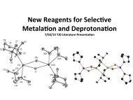
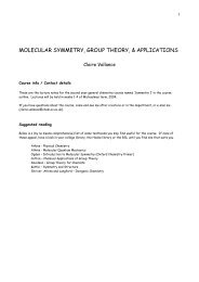
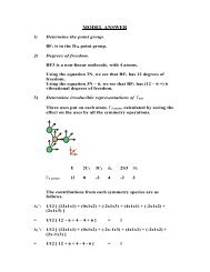
Figure 3 | Device construction for <strong>droplet</strong>hydrogel<br />
DIBs. (a,b) Subtractive micromilling<br />
(Modela MDX-40A, Roland DG) was used to<br />
fabricate a device in which <strong>the</strong> <strong>droplet</strong> <strong>interface</strong><br />
2.10<br />
<strong>bilayers</strong> were formed. An array of 1-mm-diameter<br />
holes machined in PMMA act as chambers for <strong>the</strong><br />
formation of individual DIBs. On <strong>the</strong> underside<br />
of <strong>the</strong> PMMA substrate, a microfluidic channel<br />
surrounding each well is machined. This allows<br />
sealing of <strong>the</strong> device with molten agarose<br />
c<br />
d<br />
to prevent leakage of lipid and oil, and also<br />
maintains hydration of <strong>the</strong> spin-coated hydrogel<br />
1<br />
layer upon which <strong>the</strong> DIB forms. (c) Image<br />
2<br />
of <strong>the</strong> device in situ: (1) The ground Ag/AgCl<br />
electrode connecting to <strong>the</strong> substrate gel. (2)<br />
The 100-µm Ag/AgCl electrode used for electrical<br />
3<br />
measurements inside <strong>droplet</strong>s. (3) The DHB<br />
device attached to <strong>the</strong> bottom of <strong>the</strong> Faraday<br />
cage. White tape is used to seal <strong>the</strong> agarose<br />
channel. Black tape is used to mount <strong>the</strong><br />
device on <strong>the</strong> microscope. (d) Droplet incubation chamber. A chamber for <strong>droplet</strong> incubation was prepared by micromilling 43 mm × 27 mm × 3.5 mm recesses<br />
into a planar PMMA substrate.<br />
27<br />
(iii) Remove <strong>the</strong> tape to leave an agarose-free border. This prevents electrical leakage <strong>from</strong> <strong>the</strong> underside of <strong>the</strong> device.<br />
(iv) Add membrane fragments or proteoliposomes to agarose (optional). If protein incorporation is desired, this sample<br />
(typically 1–20 µl) can be pipetted onto <strong>the</strong> agarose surface.<br />
(v) Assemble <strong>the</strong> device. The purpose of this step is both to introduce a reservoir of buffer in contact with <strong>the</strong> spin-coated<br />
agarose layer in order to maintain hydration and to create a leak-free seal around each <strong>droplet</strong>-containing well in <strong>the</strong><br />
device. The bottom of <strong>the</strong> device is constructed such that a coverslip fits flush into <strong>the</strong> device to aid in making a seal<br />
(Fig. 3). Position <strong>the</strong> device on top of <strong>the</strong> agarose-coated face of <strong>the</strong> coverslip and place it on a hot plate heated to 35 °C.<br />
? TROUBLESHOOTING<br />
(vi) Fill <strong>the</strong> agarose reservoir. By using a 200-µl pipette, fill <strong>the</strong> underside cavity of <strong>the</strong> device with agarose (3.25% wt/vol<br />
in an appropriate experimental buffer) via <strong>the</strong> connecting fill-holes on <strong>the</strong> upper side of <strong>the</strong> PMMA device (Fig. 3).<br />
(vii) Place <strong>the</strong> ground Ag/AgCl electrode into <strong>the</strong> fill-hole before <strong>the</strong> agarose sets.<br />
(viii) Cover <strong>the</strong> agarose fill-holes on <strong>the</strong> upper side of <strong>the</strong> device with adhesive tape to prevent dehydration.<br />
(ix) Transfer to a microscope. Place <strong>the</strong> device within a Faraday cage mounted on an inverted microscope.<br />
(x) Form a monolayer on <strong>the</strong> agarose surface (Fig. 1b). Pipette <strong>the</strong> lipid in hexadecane solution (9.5 mg ml − 1 ) into each<br />
well of <strong>the</strong> assembled device.<br />
(xi) Incubate <strong>the</strong> <strong>droplet</strong>s (Fig. 1b). Fill <strong>the</strong> <strong>droplet</strong> incubation chamber with <strong>the</strong> lipid in hexadecane solution (9.5 mg ml − 1 )<br />
and pipette approximately three 200-nl <strong>droplet</strong>s into each groove in <strong>the</strong> chamber. The <strong>droplet</strong> solution can<br />
contain proteoliposomes or detergent-solubilized proteins, if <strong>the</strong> incorporation of membrane proteins via <strong>the</strong> <strong>droplet</strong><br />
is required.<br />
(xii) Wait. Allow 20 min until monolayer assembly is complete.<br />
CRITICAL STEP Allow time for monolayer formation or <strong>droplet</strong>s will fuse with <strong>the</strong> hydrogel.<br />
(xiii) Transfer <strong>droplet</strong>s to <strong>the</strong> device. Pipette individual <strong>droplet</strong>s <strong>from</strong> <strong>the</strong> incubation chamber to each of <strong>the</strong> 12 wells present<br />
in <strong>the</strong> device.<br />
(xiv) DIB formation (Fig. 1b). Bilayers form spontaneously as <strong>the</strong> <strong>droplet</strong>s touch down on <strong>the</strong> surface.<br />
? TROUBLESHOOTING<br />
(xv) Insert <strong>the</strong> electrode (optional) (Fig. 1b). By using <strong>the</strong> micromanipulator, insert <strong>the</strong> agarose-coated electrode into <strong>the</strong><br />
<strong>droplet</strong> by contacting <strong>the</strong> electrode with <strong>the</strong> <strong>droplet</strong>. This is observed as a slight deformation of <strong>the</strong> <strong>droplet</strong>. The electrode<br />
does not need to be forced into <strong>the</strong> <strong>droplet</strong>. After ~30 s, <strong>the</strong> <strong>droplet</strong> will spontaneously move onto <strong>the</strong> electrode.<br />
Connect both <strong>the</strong> electrodes to a patch-clamp amplifier to make conventional electrical recordings of ionic current.<br />
? TROUBLESHOOTING<br />
(xvi) Imaging <strong>the</strong> bilayer (optional) (Fig. 1b). The DIB is now formed on <strong>the</strong> agarose surface and positioned on an inverted<br />
microscope. Optical microscopy can <strong>the</strong>n be used to image <strong>the</strong> bilayer, including TIRF imaging.<br />
? TROUBLESHOOTING<br />
43<br />
b<br />
4.20<br />
3.50<br />
0.90<br />
0.50<br />
ø0.50<br />
ø2<br />
3.50<br />
0.20<br />
nature protocols | VOL.8 NO.6 | 2013 | 1053
protocol<br />
? TROUBLESHOOTING<br />
Troubleshooting advice can be found in Table 1.<br />
Table 1 | Troubleshooting table.<br />
Step Problem Possible reason Solution<br />
1A(vi), 1B(xiv)<br />
Droplets fuse shortly after<br />
bilayer formation<br />
Osmotic imbalance<br />
Check <strong>the</strong> osmotic balance of<br />
buffers<br />
O<strong>the</strong>r amphiphiles are present. This may be<br />
diagnosed before fusion by <strong>the</strong> growth of<br />
unusually large <strong>bilayers</strong>; a result of reduced<br />
interfacial tension<br />
Check reagents for <strong>the</strong> presence of<br />
excess of detergent<br />
© 2013 Nature America, Inc. All rights reserved.<br />
Droplets do not form<br />
<strong>bilayers</strong><br />
O<strong>the</strong>r lipid structures prevent monolayer contact<br />
1B(v) Agarose fills <strong>the</strong> wells Agarose solution is not sufficiently viscous.<br />
Agarose gelation is influenced by pH and ionic<br />
strength<br />
1B(xiv)<br />
1B(xv, xvi)<br />
Droplets fuse on contact<br />
with agarose<br />
Droplets shrink or grow<br />
over time<br />
Poor seal between device and coverslip surface<br />
One or both monolayers are not formed<br />
O<strong>the</strong>r amphiphiles are present<br />
Osmotic imbalance or partitioning of water into<br />
<strong>the</strong> oil phase<br />
Decrease lipid concentration.<br />
Reduce incubation time in Step<br />
1A(v) or Step 1B(xii)<br />
Increase <strong>the</strong> agarose concentration<br />
Reassemble <strong>the</strong> device<br />
Increase lipid concentration by<br />
10%. Increase incubation time in<br />
Step 1B(xi) in 5-min increments<br />
Check reagents for <strong>the</strong> presence of<br />
detergent<br />
Check <strong>the</strong> osmotic balance of<br />
buffers<br />
1B(xv) Electrical noise Movement of <strong>droplet</strong> Reduce vibration<br />
External interference<br />
Droplet is touching <strong>the</strong> edge of <strong>the</strong> well<br />
Check whe<strong>the</strong>r <strong>the</strong> Faraday cage is<br />
grounded<br />
Move <strong>the</strong> <strong>droplet</strong> into <strong>the</strong> center of<br />
<strong>the</strong> well<br />
Current drift Evaporation; electrode corrosion Check whe<strong>the</strong>r <strong>the</strong> device is sealed<br />
and <strong>the</strong> agarose is properly hydrated<br />
1B(xvi)<br />
Cannot image bilayer using<br />
TIRF excitation<br />
Agarose layer is too thick<br />
Adjust <strong>the</strong> agarose concentration<br />
and spin-coater parameters<br />
● TIMING<br />
Reagent Setup<br />
Vesicle preparation: 1 h<br />
Agarose preparation: 5 min<br />
Electrode preparation: 30 min<br />
Lipid in hexadecane solution preparation: 45 min<br />
Electrode preparation: 18 h<br />
Equipment Setup<br />
Surface preparation: 10 min<br />
Procedural Steps<br />
Step 1A, <strong>droplet</strong>-<strong>droplet</strong> <strong>bilayers</strong>: 8 min<br />
Step 1A(i–iv), preparation: 5 min<br />
Step A(v), incubate monolayers: 2 min<br />
Step 1A(vi,vii), bilayer formation: 1 min<br />
Step 1B, <strong>droplet</strong>-hydrogel <strong>bilayers</strong>: 30 min<br />
1054 | VOL.8 NO.6 | 2013 | nature protocols
protocol<br />
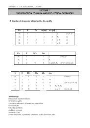
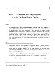
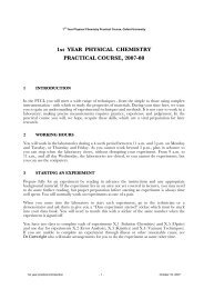
Figure 4 | Optical and electrical measurement of<br />
<strong>droplet</strong>s. (a) Capacitance measured during bilayer<br />
formation by <strong>the</strong> application of a triangular<br />
potential. The bilayer again corresponds to<br />
<strong>the</strong> white circle at <strong>the</strong> center of <strong>the</strong> image<br />
within <strong>the</strong> <strong>droplet</strong>. The <strong>droplet</strong> edge appears<br />
as a darker ring. (b) Stepwise changes in ionic<br />
current corresponding to individual insertions<br />
of S. aureus α-hemolysin protein pores into <strong>the</strong><br />
bilayer prepared as described in ref. 21. (Buffer:<br />
10 mM Tris-HCl, 0.5 M NaCl, pH 8.0. Applied<br />
potential: + 100 mV). Scale bar, 200 µm.<br />
a<br />
100 pF<br />
200 ms<br />
No bilayer<br />
Bilayer<br />
b<br />
50 pA<br />
5 s<br />
Step 1B(i–ix), assemble device: 7 min<br />
Step 1B(x–xiii), incubate monolayers: 20 min<br />
Step 1B(xiv), bilayer formation: 1 min<br />
Step 1B(xv,xvi), insert electrodes and image: 2 min<br />
© 2013 Nature America, Inc. All rights reserved.<br />
ANTICIPATED RESULTS<br />
With this protocol, one should be able to create DIBs. This protocol provides procedures for making both <strong>droplet</strong>-<strong>droplet</strong> and<br />
<strong>droplet</strong>-hydrogel variants of DIBs.<br />
Bilayer imaging<br />
Typical example images obtained during <strong>the</strong> steps of this protocol are shown in Figure 1. A range of representative <strong>droplet</strong>hydrogel<br />
<strong>bilayers</strong> <strong>from</strong> a range of different lipid compositions is shown in Figure 3. Little obvious difference in appearance is<br />
seen as <strong>the</strong> lipid composition changes. Bilayers incorporating proteins show no visible differences.<br />
Electrical recording<br />
A typical electrical response <strong>from</strong> a DIB is shown in Figure 4. Figure 4a shows <strong>the</strong> capacitate response of <strong>the</strong> system during<br />
bilayer formation. Capacitance is measured by monitoring <strong>the</strong> square-wave current output upon application of a triangularwave<br />
input voltage 44 . The trace indicates an increase in capacitance as <strong>the</strong> bilayer forms.<br />
The most definitive measure of successful bilayer formation<br />
is <strong>the</strong> recording of ionic currents through a single ion<br />
a<br />
100<br />
channel or pore embedded in <strong>the</strong> bilayer. For <strong>the</strong>se integral<br />
membrane proteins to function, <strong>the</strong>y must span a single<br />
lipid bilayer and elicit a characteristic current. Figure 4b<br />
shows one example of this and demonstrates successive<br />
insertion events of <strong>the</strong> pore-forming toxin α-hemolysin <strong>from</strong><br />
S. aureus. This protein was produced by following <strong>the</strong><br />
procedures used in our previously published work 25 . Each<br />
stepwise increase in current corresponds to an individual<br />
α-hemolysin pore inserting into <strong>the</strong> bilayer.<br />
b<br />
80<br />
60<br />
40<br />
20<br />
40<br />
Bilayer formation<br />
Data showing <strong>the</strong> variation in bilayer stability and<br />
formation rate are presented in Figure 5 for a DPhPC in<br />
Immediate rupture (%)<br />
Formation time (min)<br />
30<br />
20<br />
10<br />
Figure 5 | Stability and lifetime data <strong>from</strong> 300-nl <strong>droplet</strong> hydrogel <strong>bilayers</strong><br />
of aqueous buffer (Tris-HCl pH 8.0, 0.5 M NaCl) formed in a range of<br />
concentrations of DPhPC lipid (32 <strong>droplet</strong>s at each lipid concentration).<br />
Lipid solutions were prepared <strong>from</strong> a single stock of DPhPC in hexadecane.<br />
Droplets were equilibrated in lipid hexadecane for 5 min before imaging.<br />
(a) The proportion of <strong>droplet</strong>s that burst immediately is shown. (b) For<br />
those <strong>droplet</strong>s that do not immediately rupture, <strong>the</strong> time <strong>from</strong> <strong>droplet</strong><br />
addition to a well in <strong>the</strong> device to bilayer formation increases with lipid<br />
concentration. Devices were prepared ~10 min before <strong>droplet</strong> addition.<br />
Bilayers do not form without lipid (×). (c) Bilayer lifetime increases<br />
with lipid concentration. The experiment was terminated at 10 h for all<br />
remaining <strong>droplet</strong>s (dotted line). Error bars indicate ± 1 s.d.<br />
c<br />
Bilayer lifetime (min)<br />
0<br />
1,000<br />
100<br />
10<br />
1<br />
0.1<br />
0 2 4 6 8 10<br />
Lipid concentration (mg ml –1 )<br />
nature protocols | VOL.8 NO.6 | 2013 | 1055
protocol<br />
hexadecane DIB formed between a <strong>droplet</strong> and an agarose surface. Similar trends are observed with o<strong>the</strong>r lipid mixtures.<br />
Lipid concentration is important for bilayer formation and <strong>droplet</strong> stability. Too-low concentration will result in insufficiently<br />
assembled monolayers with subsequent <strong>droplet</strong> rupture (Fig. 5a). The o<strong>the</strong>r extreme, too-high lipid concentrations, results in<br />
increased viscosity of <strong>the</strong> solution and potentially in <strong>the</strong> formation of multilamellar lipid layers. As a result, <strong>the</strong> formation of<br />
a lipid bilayer is delayed or does not occur at all (Fig. 5b). Bilayer lifetime also correlates with lipid concentration (Fig. 5c);<br />
to obtain a stable <strong>droplet</strong>, a concentration of >5 mg ml − 1 should be used. If care is taken to prevent evaporation of <strong>the</strong> oil<br />
and to ensure <strong>the</strong> agarose remains hydrated, <strong>droplet</strong> <strong>bilayers</strong> appear to be stable indefinitely. Once formed, DIBs are stable for<br />
many weeks, given conditions that prevent dehydration of <strong>the</strong> <strong>droplet</strong>.<br />
© 2013 Nature America, Inc. All rights reserved.<br />
Acknowledgments We thank H. Bayley for his comments. This work was<br />
funded by <strong>the</strong> Biotechnology and Biological Sciences Research Council (BBSRC).<br />
M.H. is funded by <strong>the</strong> US National Science Foundation (NSF; CAREER award no.<br />
1253565). M.I.W. is funded by <strong>the</strong> European Research Council (ERC). B.C. is<br />
an Engineering and Physical Sciences Research Council (EPSRC) Life Sciences<br />
Interface (LSI) Postdoctoral Fellow.<br />
AUTHOR CONTRIBUTIONS All authors contributed equally to this work. M.H.<br />
and E.-H.L. conducted <strong>the</strong> experiments on <strong>droplet</strong>-<strong>droplet</strong> DIBs. L.C.M.G. and<br />
S.L. conducted <strong>the</strong> experiments on <strong>droplet</strong>-hydrogel DIBs. B.C., S.L. and M.I.W.<br />
prepared <strong>the</strong> figures. J.R.T. helped develop <strong>the</strong> protocol. S.L., D.P.M., O.K.C.,<br />
M.H. and M.I.W. wrote <strong>the</strong> main paper. All authors discussed <strong>the</strong> results and<br />
commented on <strong>the</strong> manuscript at all stages.<br />
COMPETING FINANCIAL INTERESTS The authors declare no competing financial<br />
interests.<br />
Reprints and permissions information is available online at http://www.nature.<br />
com/reprints/index.html.<br />
1. Sackmann, E. Supported membranes: scientific and practical applications.<br />
Science 271, 43–48 (1996).<br />
2. Dzieciol, A.J. & Mann, S. Designs for life: protocell models in <strong>the</strong><br />
laboratory. Chem. Soc. Rev. 41, 79–85 (2012).<br />
3. Fendler, J.H. Atomic and molecular clusters in membrane mimetic<br />
chemistry. Chem. Rev. 87, 877–899 (1987).<br />
4. Decher, G. Membranes and more. Membrane-mimetic approach to advanced<br />
materials. Adv. Mater. 7, 421 (1995).<br />
5. Chang, T. Artificial cells in medicine and biotechnology. Appl. Biochem.<br />
Biotechnol. 10, 5–24 (1984).<br />
6. Thutupalli, S., Herminghaus, S. & Seemannc, R. Bilayer membranes in<br />
micro-fluidics: <strong>from</strong> gel emulsions to soft functional devices. Soft Matter<br />
7, 1312–1320 (2011).<br />
7. Castell, O.K., Berridge, J. & <strong>Wallace</strong>, M.I. Quantification of membrane<br />
protein inhibition by optical ion flux in a <strong>droplet</strong> <strong>interface</strong> bilayer array.<br />
Angew. Chem. Int. Ed. Engl. 51, 3134–3138 (2012).<br />
8. Syeda, R., Holden, M.A., Hwang, W.L. & Bayley, H. Screening blockers<br />
against a potassium channel with a <strong>droplet</strong> <strong>interface</strong> bilayer array. J. Am.<br />
Chem. Soc. 130, 15543–15548 (2008).<br />
9. Castellana, E.T. & Cremer, P.S. Solid supported lipid <strong>bilayers</strong>: <strong>from</strong><br />
biophysical studies to sensor design. Surf. Sci. Rep. 61, 429–444 (2006).<br />
10. Tanaka, M. & Sackmann, E. Polymer-supported membranes as models of<br />
<strong>the</strong> cell surface. Nature 437, 656–663 (2005).<br />
11. Tamm, L.K. & McConnell, H.M. Supported phospholipid <strong>bilayers</strong>. Biophys.<br />
J. 47, 105–113 (1985).<br />
12. Dewa, T. et al. Lateral organization of a membrane protein in a supported<br />
binary lipid domain: direct observation of <strong>the</strong> organization of bacterial<br />
light-harvesting complex 2 by total internal reflection fluorescence<br />
microscopy. Langmuir 22, 5412–5418 (2006).<br />
13. Atanasov, V. et al. Membrane on a chip: a functional te<strong>the</strong>red lipid bilayer<br />
membrane on silicon oxide surfaces. Biophys. J. 89, 1780–1788 (2005).<br />
14. Rawle, R.J., van Lengerich, B., Chung, M., Bendix, P.M. & Boxer, S.G.<br />
Vesicle fusion observed by content transfer across a te<strong>the</strong>red lipid bilayer.<br />
Biophys. J. 101, L37–L39.<br />
15. Mueller, P., Rudin, D.O., Ti Tien, H. & Wescott, W.C. Reconstitution of cell<br />
membrane structure in vitro and its transformation into an excitable<br />
system. Nature 194, 979–980 (1962).<br />
16. Montal, M. & Mueller, P. Formation of bimolecular membranes <strong>from</strong> lipid<br />
monolayers and a study of <strong>the</strong>ir electrical properties. Proc. Natl. Acad.<br />
Sci. USA 69, 3561–3566 (1972).<br />
17. Cheng, H.T. & London, E. Preparation and properties of asymmetric large<br />
unilamellar vesicles: interleaflet coupling in asymmetric vesicles is<br />
dependent on temperature but not curvature. Biophys. J. 100, 2671–2678<br />
(2011).<br />
18. Richmond, D.L. et al. Forming giant vesicles with controlled membrane<br />
composition, asymmetry, and contents. Proc. Natl. Acad. Sci. USA 108,<br />
9431–9436 (2011).<br />
19. Szoka Jr., F. & Papahadjopoulos, D. Comparative properties and methods<br />
of preparation of lipid vesicles (liposomes). Annu. Rev. Biophys. Bioeng. 9,<br />
467–508 (1980).<br />
20. Bayley, H. et al. Droplet <strong>interface</strong> <strong>bilayers</strong>. Mol. Biosyst. 4, 1191–1208<br />
(2008).<br />
21. Holden, M.A., Needham, D. & Bayley, H. Functional bionetworks <strong>from</strong><br />
nanoliter water <strong>droplet</strong>s. J. Am. Chem. Soc. 129, 8650–8655 (2007).<br />
22. Maglia, G. et al. Droplet networks with incorporated protein diodes show<br />
collective properties. Nat. Nanotechnol. 4, 437–440 (2009).<br />
23. Hwang, W.L., Chen, M., Cronin, B., Holden, M.A. & Bayley, H. Asymmetric<br />
<strong>droplet</strong> <strong>interface</strong> <strong>bilayers</strong>. J. Am. Chem. Soc. 130, 5878–5879 (2008).<br />
24. Gross, L.C., Castell, O.K. & <strong>Wallace</strong>, M.I. Dynamic and reversible control of<br />
2D membrane protein concentration in a <strong>droplet</strong> <strong>interface</strong> bilayer.<br />
Nano Lett. 11, 3324–3328 (2011).<br />
25. Heron, A.J., Thompson, J.R., Cronin, B., Bayley, H. & <strong>Wallace</strong>, M.I.<br />
Simultaneous measurement of ionic current and fluorescence <strong>from</strong> single<br />
protein pores. J. Am. Chem. Soc. 131, 1652–1653 (2009).<br />
26. Heron, A.J., Thompson, J.R., Mason, A.E. & <strong>Wallace</strong>, M.I. Direct detection<br />
of membrane channels <strong>from</strong> gels using water-in-oil <strong>droplet</strong> <strong>bilayers</strong>.<br />
J. Am. Chem. Soc. 129, 16042–16047 (2007).<br />
27. Leptihn, S., Thompson, J.R., Ellory, J.C., Tucker, S.J. & <strong>Wallace</strong>, M.I.<br />
In vitro reconstitution of eukaryotic ion channels using <strong>droplet</strong> <strong>interface</strong><br />
<strong>bilayers</strong>. J. Am. Chem. Soc. 133, 9370–9375 (2011).<br />
28. Funakoshi, K., Suzuki, H. & Takeuchi, S. Lipid bilayer formation by<br />
contacting monolayers in a microfluidic device for membrane protein<br />
analysis. Anal. Chem. 78, 8169–8174 (2006).<br />
29. Malmstadt, N., Nash, M.A., Purnell, R.F. & Schmidt, J.J. Automated<br />
formation of lipid-bilayer membranes in a microfluidic device. Nano Lett.<br />
6, 1961–1965 (2006).<br />
30. Jeon, T.J., Malmstadt, N., Poulos, J.L. & Schmidt, J.J. Black lipid<br />
membranes stabilized through substrate conjugation to a hydrogel.<br />
Biointerphases 3, FA96 (2008).<br />
31. Poulos, J.L., Portonovo, S.A., Bang, H. & Schmidt, J.J. Automatable lipid<br />
bilayer formation and ion channel measurement using sessile <strong>droplet</strong>s.<br />
J. Phys. Condens. Matter. 22, 454105 (2010).<br />
32. Poulos, J.L. et al. Ion channel and toxin measurement using a highthroughput<br />
lipid membrane platform. Biosens. Bioelectron. 24, 1806–1810<br />
(2009).<br />
33. Takinoue, M. & Takeuchi, S. Droplet microfluidics for <strong>the</strong> study of artificial<br />
cells. Anal. Bioanal. Chem. 400, 1705–1716 (2011).<br />
34. Coste, B. et al. Piezo proteins are pore-forming subunits of mechanically<br />
activated channels. Nature 483, 176–181 (2012).<br />
35. Sarles, S.A. & Leo, D.J. Physical encapsulation of <strong>droplet</strong> <strong>interface</strong><br />
<strong>bilayers</strong> for durable, portable biomolecular networks. <strong>Lab</strong>. Chip 10,<br />
710–717 (2010).<br />
36. Jeon, T.J., Poulos, J.L. & Schmidt, J.J. Long-term storable and shippable<br />
lipid bilayer membrane platform. <strong>Lab</strong>. Chip 8, 1742–1744 (2008).<br />
37. Stanley, C.E. et al. A microfluidic approach for high-throughput<br />
<strong>droplet</strong> <strong>interface</strong> bilayer (DIB) formation. Chem. Commun. 46, 1620–1622<br />
(2010).<br />
38. Jason, L.P., Wyatt, C.N., Tae-Joon, J., Chang-Jin, C.J.K. & Jacob, J.S.<br />
Electrowetting on dielectric-based microfluidics for integrated lipid bilayer<br />
formation and measurement. Appl. Phys. Lett. 95, 013706 (2009).<br />
1056 | VOL.8 NO.6 | 2013 | nature protocols
protocol<br />
© 2013 Nature America, Inc. All rights reserved.<br />
39. Hu, P.C., Li, S. & Malmstadt, N. Microfluidic fabrication of asymmetric<br />
giant lipid vesicles. ACS Appl. Mater. Interfaces 3, 1434–1440 (2011).<br />
40. Dixit, S.S., Kim, H., Vasilyev, A., Eid, A. & Faris, G.W. Light-driven<br />
formation and rupture of <strong>droplet</strong> <strong>bilayers</strong>. Langmuir 26, 6193–6200 (2010).<br />
41. Punnamaraju, S., You, H. & Steckl, A.J. Triggered release of molecules<br />
across <strong>droplet</strong> <strong>interface</strong> bilayer lipid membranes using photopolymerizable<br />
lipids. Langmuir 28, 7657–7664 (2012).<br />
42. Portonovo, S.A. & Schmidt, J. Masking apertures enabling automation and<br />
solution exchange in sessile <strong>droplet</strong> lipid <strong>bilayers</strong>. Biomed. Microdevices<br />
14, 187–191 (2012).<br />
43. Punnamaraju, S. & Steckl, A.J. Voltage control of <strong>droplet</strong> <strong>interface</strong> bilayer<br />
lipid membrane dimensions. Langmuir 27, 618–626 (2011).<br />
44. Gross, L.C., Heron, A.J., Baca, S.C. & <strong>Wallace</strong>, M.I. Determining membrane<br />
capacitance by dynamic control of <strong>droplet</strong> <strong>interface</strong> bilayer area. Langmuir<br />
27, 14335–14342 (2011).<br />
45. Huang, J., Lein, M., Gunderson, C. & Holden, M.A. Direct quantitation of<br />
peptide-mediated protein transport across a <strong>droplet</strong>-<strong>interface</strong> bilayer.<br />
J. Am. Chem. Soc. 133, 15818–15821 (2011).<br />
46. Fischer, A., Holden, M.A., Pentelute, B.L. & Collier, R.J. Ultrasensitive<br />
detection of protein translocated through toxin pores in <strong>droplet</strong>-<strong>interface</strong><br />
<strong>bilayers</strong>. Proc. Natl. Acad. Sci USA 108, 16577–16581 (2011).<br />
47. Thompson, J.R., Heron, A.J., Santoso, Y. & <strong>Wallace</strong>, M.I. Enhanced<br />
stability and fluidity in <strong>droplet</strong> on hydrogel <strong>bilayers</strong> for measuring<br />
membrane protein diffusion. Nano Lett. 7, 3875–3878 (2007).<br />
48. Xu, J., Sigworth, F.J. & LaVan, D.A. Syn<strong>the</strong>tic protocells to mimic and test<br />
cell function. Adv. Mater. 22, 120–127 (2010).<br />
49. Harriss, L.M., Cronin, B., Thompson, J.R. & <strong>Wallace</strong>, M.I. Imaging multiple<br />
conductance states in an alamethicin pore. J. Am. Chem. Soc. 133,<br />
14507–14509 (2011).<br />
50. Tien, H.T. & Ottova, A.L. The lipid bilayer concept and its experimental<br />
realization: <strong>from</strong> soap bubbles, kitchen sink, to bilayer lipid membranes.<br />
J. Memb. Sci. 189, 83–117 (2001).<br />
51. Haverkamp, R. Membrane magic and <strong>the</strong> magic of membranes: planar lipid<br />
<strong>bilayers</strong> (BLMs) and <strong>the</strong>ir applications. Biotechnol. Adv. 22, 311–312 (2004).<br />
52. Blodgett, K.B. Monomolecular films of fatty acids on glass. J. Am. Chem.<br />
Soc. 56, 495–495 (1934).<br />
53. Langmuir, I. The constitution and fundamental properties of solids and<br />
liquids. II. Liquids.1. J. Am. Chem. Soc. 39, 1848–1906 (1917).<br />
54. Petty, M.C. Langmuir-Blodgett Films (Cambridge University Press,<br />
1996).<br />
55. Morales-Penningston, N.F. et al. GUV preparation and imaging: minimizing<br />
artifacts. Biochim. Biophys. Acta. 1798, 1324–1332 (2010).<br />
56. Montes, L.R., Alonso, A., Goni, F.M. & Bagatolli, L.A. Giant unilamellar<br />
vesicles electroformed <strong>from</strong> native membranes and organic lipid mixtures<br />
under physiological conditions. Biophys. J. 93, 3548–3554 (2007).<br />
57. Zagnoni, M. Miniaturised technologies for <strong>the</strong> development of artificial<br />
lipid bilayer systems. <strong>Lab</strong>. Chip 12, 1026–1039 (2012).<br />
58. Suzuki, H. & Takeuchi, S. Microtechnologies for membrane protein studies.<br />
Anal. Bioanal. Chem. 391, 2695–2702 (2008).<br />
59. Aghdaei, S., Sandison, M.E., Zagnoni, M., Green, N.G. & Morgan, H.<br />
Formation of artificial lipid <strong>bilayers</strong> using <strong>droplet</strong> dielectrophoresis.<br />
<strong>Lab</strong>. Chip 8, 1617–1620 (2008).<br />
60. Malmstadt, N., Hoffman, A.S. & Stayton, P.S. ‘Smart’ mobile affinity matrix<br />
for microfluidic immunoassays. <strong>Lab</strong>. Chip 4, 412–415 (2004).<br />
61. White, S.H. Ion Channel Reconstitution (ed. Milller, C.) (Plenum Press,<br />
1986).<br />
62. Rigaud, J.L. & Levy, D. Reconstitution of membrane proteins into<br />
liposomes. Methods Enzymol. 372, 65–86 (2003).<br />
63. Paternostre, M.T., Roux, M. & Rigaud, J.L. Mechanisms of membrane<br />
protein insertion into liposomes during reconstitution procedures involving<br />
<strong>the</strong> use of detergents. 1. Solubilization of large unilamellar liposomes<br />
(prepared by reverse-phase evaporation) by triton X-100, octyl glucoside,<br />
and sodium cholate. Biochemistry 27, 2668–2677 (1988).<br />
64. Schimerlik, M.I. Overview of membrane protein solubilization. Curr. Protoc.<br />
Neurosci. published online; http://dx.doi.org/10.1002/0471142301.ns0509s02<br />
(1 May 2001).<br />
65. Hanke, W. & Schule, W.R. Planar Lipid Bilayers: Methods and Applications<br />
(Academic Press, 1993).<br />
nature protocols | VOL.8 NO.6 | 2013 | 1057